Concealed hinges for the cabinet and furniture … · Bisagras serie F para puertas de grandes...
76
Concealed hinges for the cabinet and furniture industries Bisagras invisibles para la industria del mueble
Transcript of Concealed hinges for the cabinet and furniture … · Bisagras serie F para puertas de grandes...
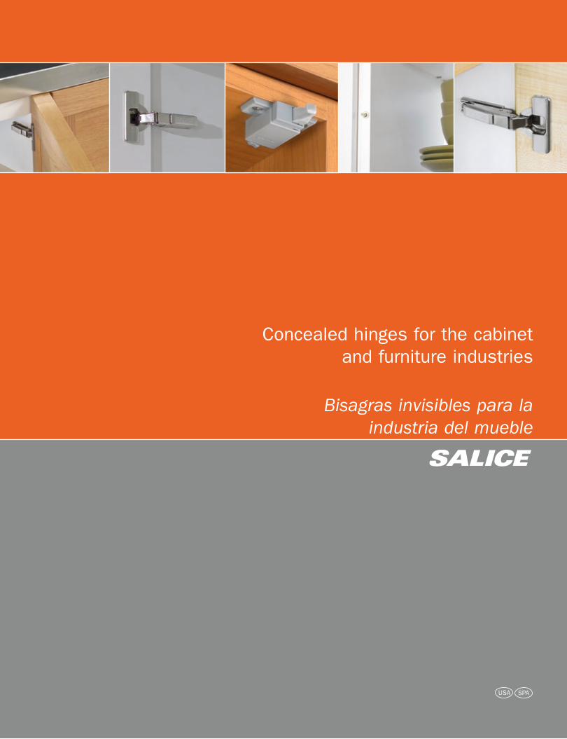
Concealed hinges for the cabinet and furniture industries
Bisagras invisibles para laindustria del mueble
italiano
giapponese
coreano
indi
arabo
cinese
spagnolo
inglese
francese
tedesco
russo
portoghese
romeno
italiano
giapponese
coreano
indi
arabo
cinese
spagnolo
inglese
francese
tedesco
russo
portoghese
romeno
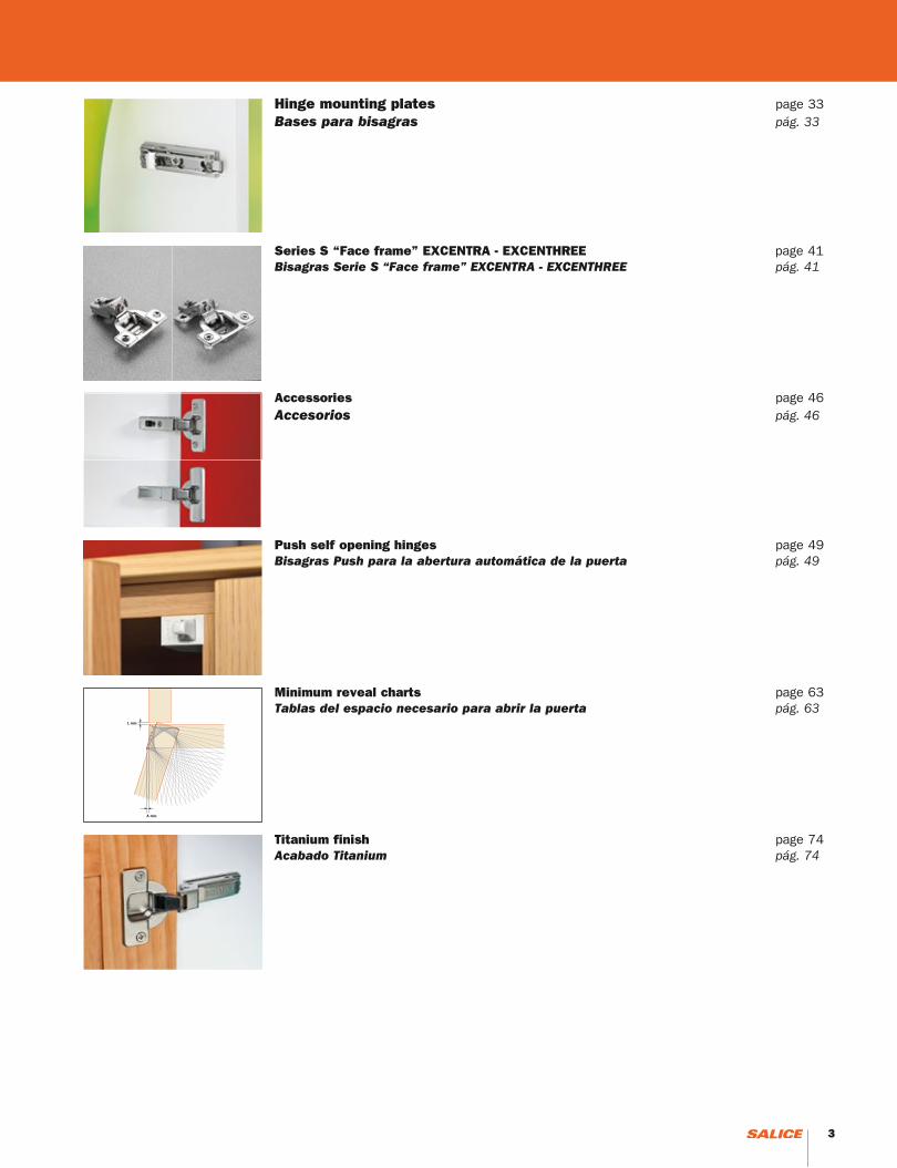
Series M Hinges - Single pivot 270° page 24Bisagras Serie M - Abertura 270° pág. 24
IndexIndex
Technical information page 4Informaciones técnicas pág. 4
Series 200 Hinges page 13Bisagras Serie 200 pág. 13
Series F Hinges for thick doors up to 1-1/2” page 28 Bisagras serie F para puertas de grandes espesores hasta 1-1/2” pág. 28
Series 100 Hinges shallow cup page 23Bisagras serie 100, profundidad de la cazoleta reducida pág. 23
Series B Hinges for wood doors with special profiles page 22Bisagras serie B para puertas de madera con perfiles especiales pág. 22
Overlay charts page 29 Tablas de cobertura pág. 29
2 3
Hinge mounting plates page 33 Bases para bisagras pág. 33
Series S “Face frame” EXCENTRA - EXCENTHREE page 41Bisagras Serie S “Face frame” EXCENTRA - EXCENTHREE pág. 41
Accessories page 46Accesorios pág. 46
Push self opening hinges page 49Bisagras Push para la abertura automática de la puerta pág. 49
Minimum reveal charts page 63Tablas del espacio necesario para abrir la puerta pág. 63
Titanium finish page 74 Acabado Titanium pág. 74
2 3
General informationInformaciones generales
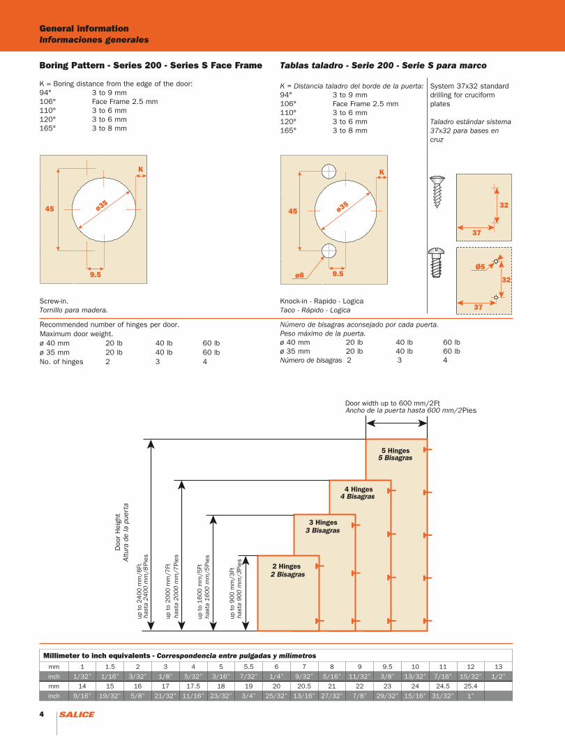
Boring Pattern - Series 200 - Series S Face Frame
K = Boring distance from the edge of the door:94° 3 to 9 mm106° Face Frame 2.5 mm110° 3 to 6 mm120° 3 to 6 mm165° 3 to 8 mm
45 ø35
K
9.5
45 ø35
K
9.5ø8
Pies
Pies
Pies
Pies
FtPies
Screw-in.Tornillo para madera.
Knock-in - Rapido - LogicaTaco - Rápido - Logica
Recommended number of hinges per door.Maximum door weight.ø 40 mm 20 lb 40 lb 60 lbø 35 mm 20 lb 40 lb 60 lbNo. of hinges 2 3 4
Tablas taladro - Serie 200 - Serie S para marco
K = Distancia taladro del borde de la puerta:94° 3 to 9 mm106° Face Frame 2.5 mm110° 3 to 6 mm120° 3 to 6 mm165° 3 to 8 mm
Número de bisagras aconsejado por cada puerta.Peso máximo de la puerta.ø 40 mm 20 lb 40 lb 60 lbø 35 mm 20 lb 40 lb 60 lbNúmero de bisagras 2 3 4
Millimeter to inch equivalents - Correspondencia entre pulgadas y milímetrosmm 1 1.5 2 3 4 5 5.5 6 7 8 9 9.5 10 11 12 13
inch 1/32” 1/16” 3/32” 1/8” 5/32” 3/16” 7/32” 1/4” 9/32” 5/16” 11/32” 3/8” 13/32” 7/16” 15/32” 1/2”
mm 14 15 16 17 17.5 18 19 20 20.5 21 22 23 24 24.5 25.4
inch 9/16” 19/32” 5/8” 21/32” 11/16” 23/32” 3/4” 25/32” 13/16” 27/32” 7/8” 29/32” 15/16” 31/32” 1”
32
37
Ø5
32
37
System 37x32 standard drilling for cruciform plates
Taladro estándar sistema 37x32 para bases en cruz
4 5
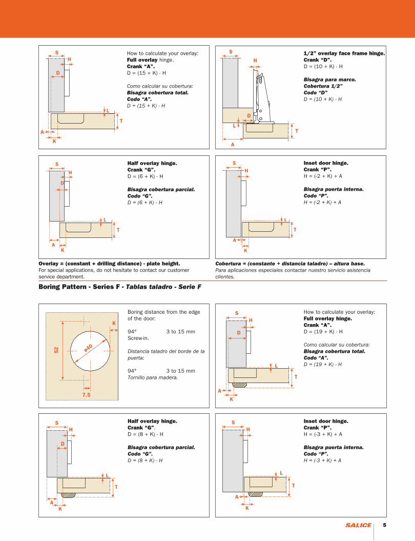
Boring Pattern - Series F - Tablas taladro - Serie F
Boring distance from the edge of the door:
94° 3 to 15 mmScrew-in.
Distancia taladro del borde de la puerta:
94° 3 to 15 mmTornillo para madera.
How to calculate your overlay:Full overlay hinge.Crank “A”.D = (19 + K) - H
Como calcular su cobertura:Bisagra cobertura total.Codo “A”.D = (19 + K) - H
Half overlay hinge.Crank “G”.D = (8 + K) - H
Bisagra cobertura parcial.Codo “G”.D = (8 + K) - H
Inset door hinge.Crank “P”.H = (-3 + K) + A
Bisagra puerta interna.Codo “P”.H = (-3 + K) + A
How to calculate your overlay:Full overlay hinge.Crank “A”.D = (15 + K) - H
Como calcular su cobertura:Bisagra cobertura total.Codo “A”.D = (15 + K) - H
1/2” overlay face frame hinge.Crank “D”.D = (10 + K) - H
Bisagra para marco. Cobertura 1/2”Codo “D”D = (10 + K) - H
Half overlay hinge.Crank “G”.D = (6 + K) - H
Bisagra cobertura parcial.Codo “G”.D = (6 + K) - H
Inset door hinge.Crank “P”.H = (-2 + K) + A
Bisagra puerta interna.Codo “P”.H = (-2 + K) + A
Overlay = (constant + drilling distance) - plate height. For special applications, do not hesitate to contact our customer service department.
Cobertura = (constante + distancia taladro) – altura base.Para aplicaciones especiales contactar nuestro servicio asistencia clientes.
4 5
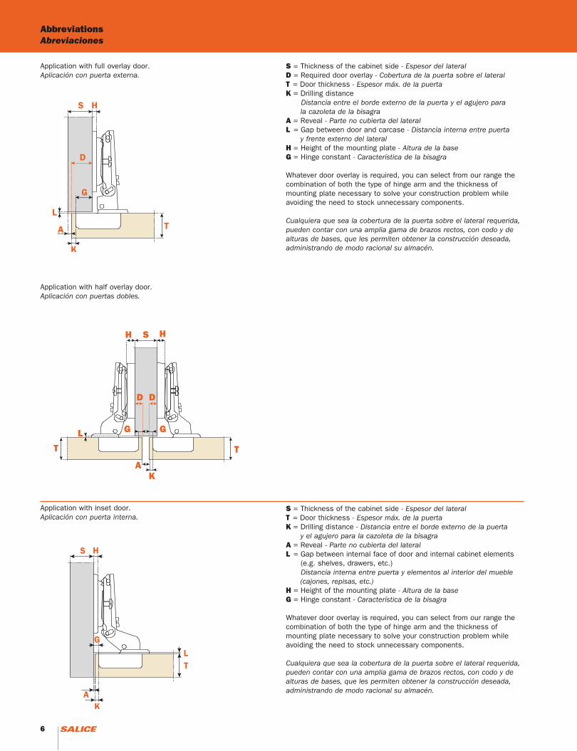
AbbreviationsAbreviaciones
Application with full overlay door.Aplicación con puerta externa.
Application with half overlay door.Aplicación con puertas dobles.
Application with inset door.Aplicación con puerta interna.
S = Thickness of the cabinet side - Espesor del lateralD = Required door overlay - Cobertura de la puerta sobre el lateralT = Door thickness - Espesor máx. de la puertaK = Drilling distance Distancia entre el borde externo de la puerta y el agujero para la cazoleta de la bisagraA = Reveal - Parte no cubierta del lateralL = Gap between door and carcase - Distancia interna entre puerta y frente externo del lateralH = Height of the mounting plate - Altura de la baseG = Hinge constant - Característica de la bisagra
Whatever door overlay is required, you can select from our range the combination of both the type of hinge arm and the thickness of mounting plate necessary to solve your construction problem while avoiding the need to stock unnecessary components.
Cualquiera que sea la cobertura de la puerta sobre el lateral requerida, pueden contar con una amplia gama de brazos rectos, con codo y de alturas de bases, que les permiten obtener la construcción deseada, administrando de modo racional su almacén.
S = Thickness of the cabinet side - Espesor del lateralT = Door thickness - Espesor máx. de la puertaK = Drilling distance - Distancia entre el borde externo de la puerta y el agujero para la cazoleta de la bisagraA = Reveal - Parte no cubierta del lateralL = Gap between internal face of door and internal cabinet elements (e.g. shelves, drawers, etc.) Distancia interna entre puerta y elementos al interior del mueble (cajones, repisas, etc.)H = Height of the mounting plate - Altura de la baseG = Hinge constant - Característica de la bisagra
Whatever door overlay is required, you can select from our range the combination of both the type of hinge arm and the thickness of mounting plate necessary to solve your construction problem while avoiding the need to stock unnecessary components.
Cualquiera que sea la cobertura de la puerta sobre el lateral requerida, pueden contar con una amplia gama de brazos rectos, con codo y de alturas de bases, que les permiten obtener la construcción deseada, administrando de modo racional su almacén.
H S
D D
G GL
AK
T
H
T
6 7
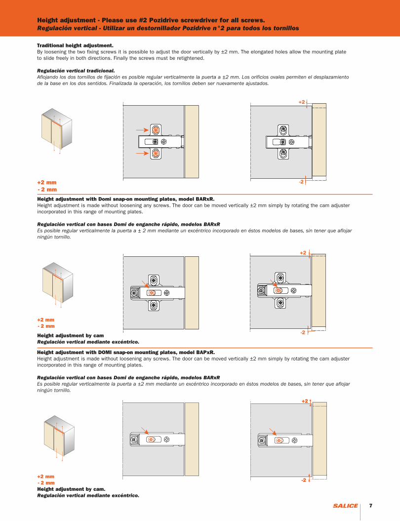
Height adjustment - Please use #2 Pozidrive screwdriver for all screws.Regulación vertical - Utilizar un destornillador Pozidrive n°2 para todos los tornillos
+2 mm - 2 mm
Traditional height adjustment.By loosening the two fixing screws it is possible to adjust the door vertically by ±2 mm. The elongated holes allow the mounting plate to slide freely in both directions. Finally the screws must be retightened.
Regulación vertical tradicional.Aflojando los dos tornillos de fijación es posible regular verticalmente la puerta a ±2 mm. Los orificios ovales permiten el desplazamiento de la base en los dos sentidos. Finalizada la operación, los tornillos deben ser nuevamente ajustados.
Height adjustment with Domi snap-on mounting plates, model BARxR. Height adjustment is made without loosening any screws. The door can be moved vertically ±2 mm simply by rotating the cam adjuster incorporated in this range of mounting plates.
Regulación vertical con bases Domi de enganche rápido, modelos BARxREs posible regular verticalmente la puerta a ± 2 mm mediante un excéntrico incorporado en éstos modelos de bases, sin tener que aflojar ningún tornillo.
Height adjustment by camRegulación vertical mediante excéntrico.
+2 mm - 2 mm
+2 mm - 2 mm
Height adjustment with DOMI snap-on mounting plates, model BAPxR.Height adjustment is made without loosening any screws. The door can be moved vertically ±2 mm simply by rotating the cam adjuster incorporated in this range of mounting plates.
Regulación vertical con bases Domi de enganche rápido, modelos BARxR Es posible regular verticalmente la puerta a ±2 mm mediante un excéntrico incorporado en éstos modelos de bases, sin tener que aflojar ningún tornillo.
Height adjustment by cam.Regulación vertical mediante excéntrico.
+2
-2
6 7
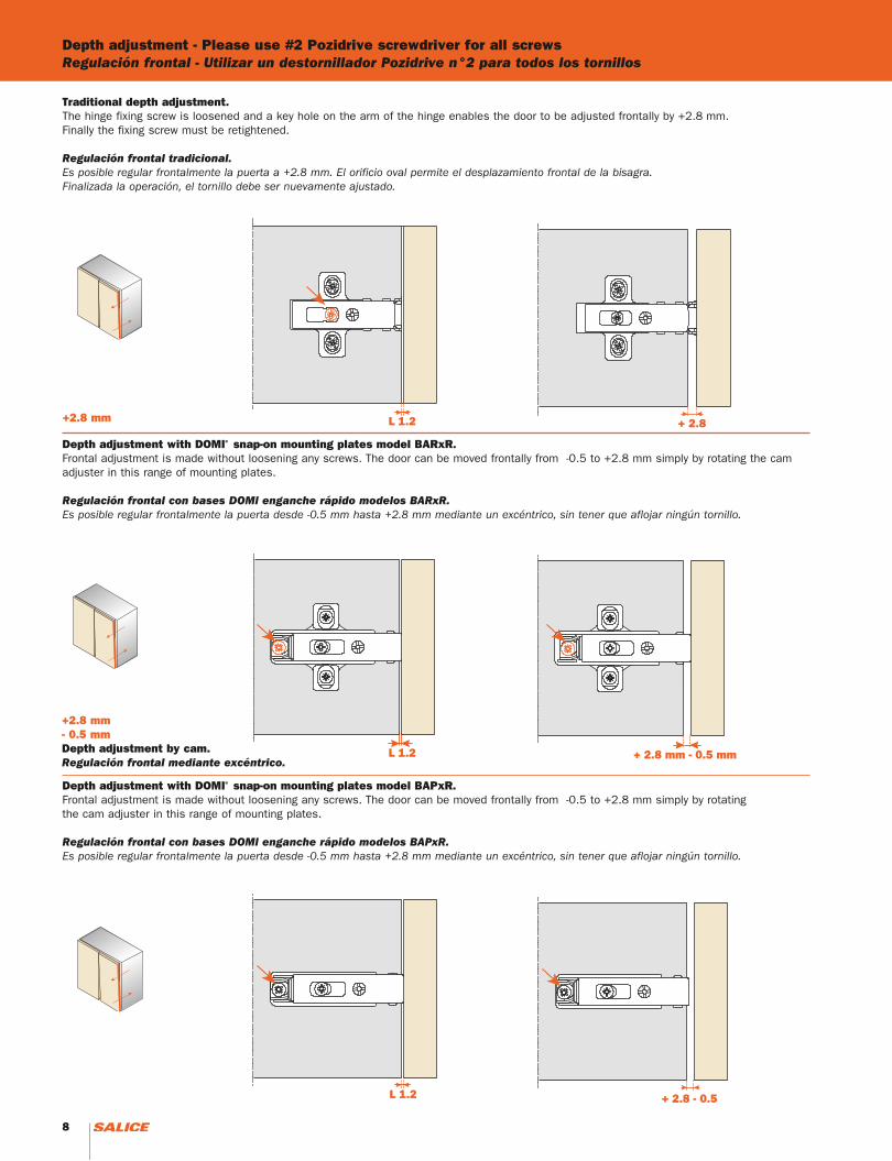
Depth adjustment - Please use #2 Pozidrive screwdriver for all screwsRegulación frontal - Utilizar un destornillador Pozidrive n°2 para todos los tornillos
L 1.2 + 2.8
L 1.2
+ 2.8 mm - 0.5 mm
L 1.2
+ 2.8 mm - 0.5 mm
Depth adjustment with DOMI® snap-on mounting plates model BARxR.Frontal adjustment is made without loosening any screws. The door can be moved frontally from -0.5 to +2.8 mm simply by rotating the cam adjuster in this range of mounting plates.
Regulación frontal con bases DOMI enganche rápido modelos BARxR. Es posible regular frontalmente la puerta desde -0.5 mm hasta +2.8 mm mediante un excéntrico, sin tener que aflojar ningún tornillo.
+2.8 mm
+2.8 mm - 0.5 mmDepth adjustment by cam.Regulación frontal mediante excéntrico.
L 1.2
+ 2.8 - 0.5
L 1.2
+ 2.8 - 0.5
Depth adjustment with DOMI® snap-on mounting plates model BAPxR.Frontal adjustment is made without loosening any screws. The door can be moved frontally from -0.5 to +2.8 mm simply by rotatingthe cam adjuster in this range of mounting plates.
Regulación frontal con bases DOMI enganche rápido modelos BAPxR.Es posible regular frontalmente la puerta desde -0.5 mm hasta +2.8 mm mediante un excéntrico, sin tener que aflojar ningún tornillo.
Traditional depth adjustment.The hinge fixing screw is loosened and a key hole on the arm of the hinge enables the door to be adjusted frontally by +2.8 mm. Finally the fixing screw must be retightened.
Regulación frontal tradicional.Es posible regular frontalmente la puerta a +2.8 mm. El orificio oval permite el desplazamiento frontal de la bisagra. Finalizada la operación, el tornillo debe ser nuevamente ajustado.
8 9
Adjustments - Please use #2 Pozidrive screwdriver for all screws Regulaciones - Utilizar un destornillador Pozidrive n°2 para todos los tornillos
L = 1
.2
L = 1
.2
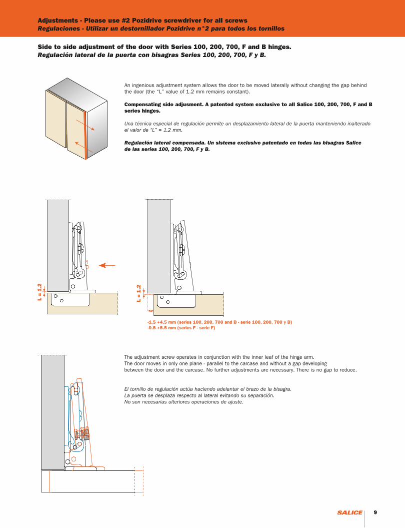
Side to side adjustment of the door with Series 100, 200, 700, F and B hinges.Regulación lateral de la puerta con bisagras Series 100, 200, 700, F y B.
An ingenious adjustment system allows the door to be moved laterally without changing the gap behind the door (the “L” value of 1.2 mm remains constant).
Compensating side adjusment. A patented system exclusive to all Salice 100, 200, 700, F and B series hinges.
Una técnica especial de regulación permite un desplazamiento lateral de la puerta manteniendo inalterado el valor de “L” = 1.2 mm.
Regulación lateral compensada. Un sistema exclusivo patentado en todas las bisagras Salice de las series 100, 200, 700, F y B.
The adjustment screw operates in conjunction with the inner leaf of the hinge arm. The door moves in only one plane - parallel to the carcase and without a gap developing between the door and the carcase. No further adjustments are necessary. There is no gap to reduce.
El tornillo de regulación actúa haciendo adelantar el brazo de la bisagra. La puerta se desplaza respecto al lateral evitando su separación. No son necesarias ulteriores operaciones de ajuste.
-1.5 +4.5 mm (series 100, 200, 700 and B - serie 100, 200, 700 y B)-0.5 +5.5 mm (series F - serie F)
8 9
Series 100, 200, 700, F and B - Assembly instructionsSeries 100, 200, 700, F y B - Instrucciones de montaje
L 1.2
1
2
3
4
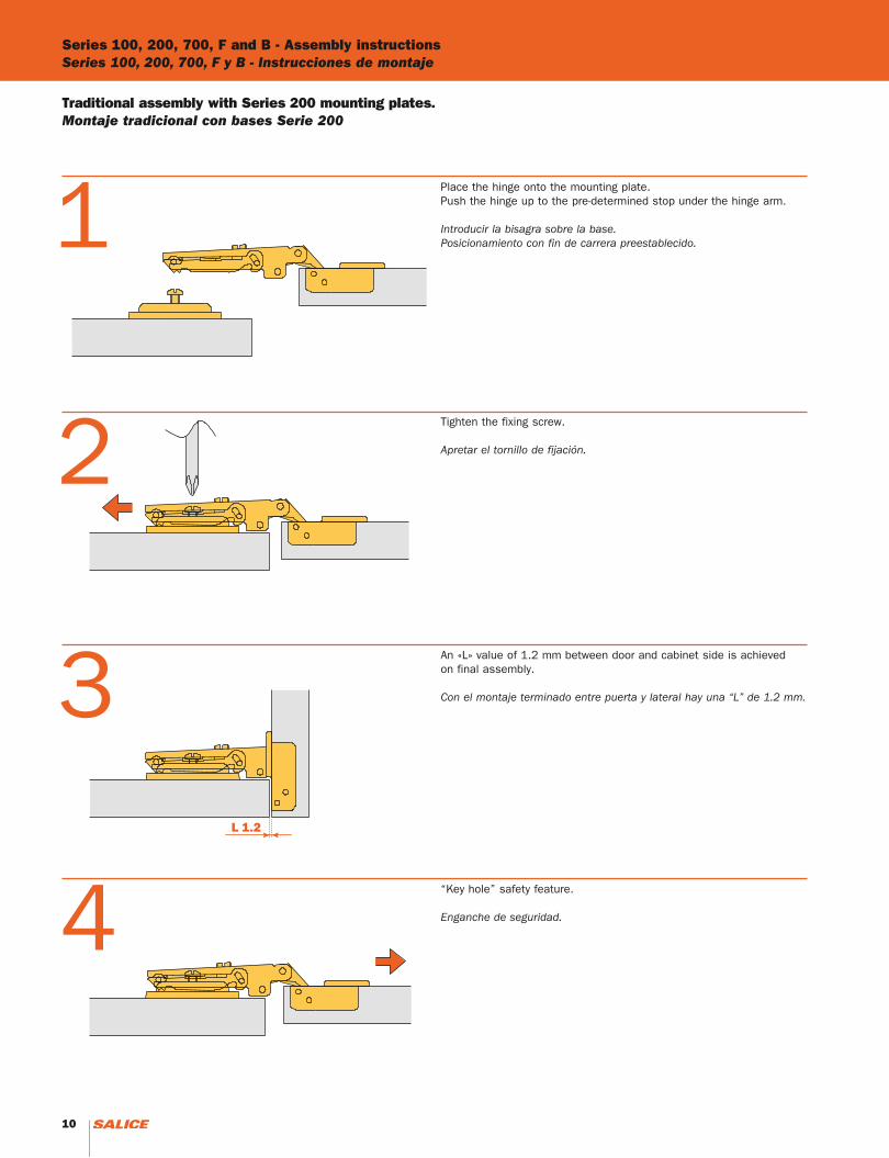
Traditional assembly with Series 200 mounting plates.Montaje tradicional con bases Serie 200
Place the hinge onto the mounting plate. Push the hinge up to the pre-determined stop under the hinge arm.
Introducir la bisagra sobre la base.Posicionamiento con fin de carrera preestablecido.
Tighten the fixing screw.
Apretar el tornillo de fijación.
An «L» value of 1.2 mm between door and cabinet side is achievedon final assembly.
Con el montaje terminado entre puerta y lateral hay una “L” de 1.2 mm.
“Key hole” safety feature.
Enganche de seguridad.
10 11
1
2
3
4
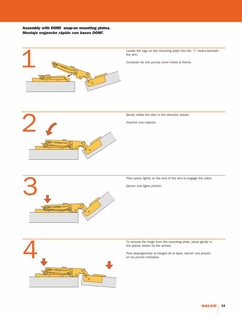
Assembly with DOMI® snap-on mounting plates.Montaje enganche rápido con bases DOMI®.
Locate the lugs on the mounting plate into the “J” hooks beneath the arm.
Contactar los dos puntos como indica la flecha.
Gently rotate the door in the direction shown.
Imprimir una rotación.
Then press lightly on the end of the arm to engage the catch.
Ejercer una ligera presión.
To remove the hinge from the mounting plate, press gently in the places shown by the arrows.
Para desenganchar la bisagra de la base, ejercer una presión en los puntos indicados.
10 11

12

HingesBisagras
13
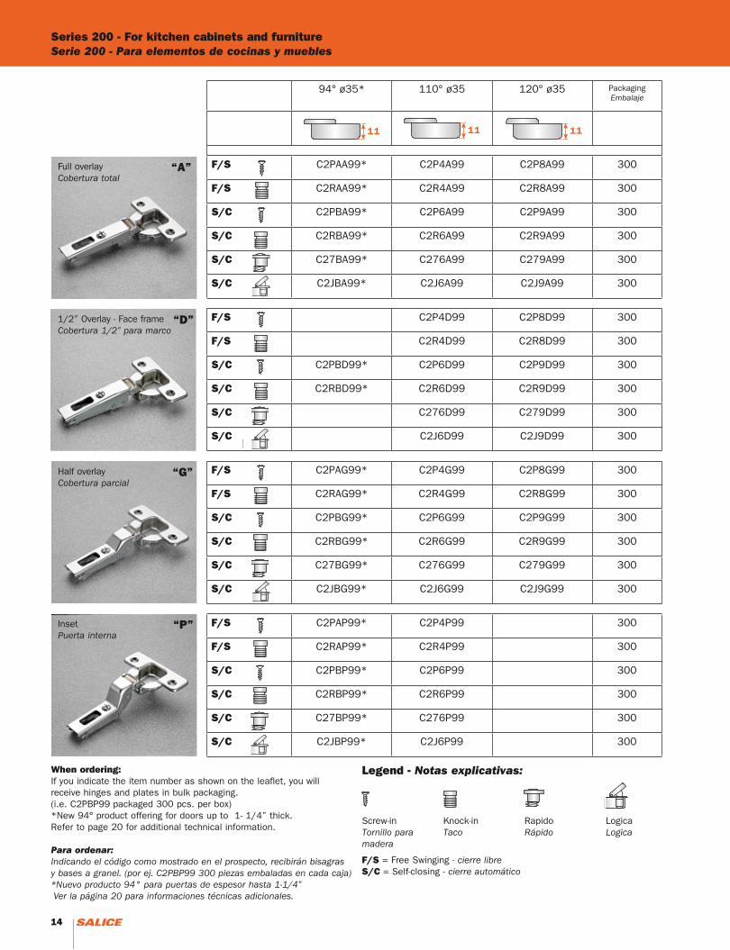
When ordering:If you indicate the item number as shown on the leaflet, you will receive hinges and plates in bulk packaging. (i.e. C2PBP99 packaged 300 pcs. per box)*New 94° product offering for doors up to 1- 1/4” thick. Refer to page 20 for additional technical information.
Para ordenar:Indicando el código como mostrado en el prospecto, recibirán bisagras y bases a granel. (por ej. C2PBP99 300 piezas embaladas en cada caja)*Nuevo producto 94° para puertas de espesor hasta 1-1/4” Ver la página 20 para informaciones técnicas adicionales.
F/S = Free Swinging - cierre libreS/C = Self-closing - cierre automático
Series 200 - For kitchen cabinets and furnitureSerie 200 - Para elementos de cocinas y muebles
Legend - Notas explicativas:
Full overlayCobertura total
1/2” Overlay - Face frameCobertura 1/2” para marco
Half overlayCobertura parcial
InsetPuerta interna
“A”
“D”
“G”
“P”
Screw-inTornillo para madera
Knock-inTaco
RapidoRápido
LogicaLogica
94° ø35* 110° ø35 120° ø35 PackagingEmbalaje
F/S C2PAA99* C2P4A99 C2P8A99 300
F/S C2RAA99* C2R4A99 C2R8A99 300
S/C C2PBA99* C2P6A99 C2P9A99 300
S/C C2RBA99* C2R6A99 C2R9A99 300
S/C C27BA99* C276A99 C279A99 300
S/C C2JBA99* C2J6A99 C2J9A99 300
F/S C2P4D99 C2P8D99 300
F/S C2R4D99 C2R8D99 300
S/C C2PBD99* C2P6D99 C2P9D99 300
S/C C2RBD99* C2R6D99 C2R9D99 300
S/C C276D99 C279D99 300
S/C C2J6D99 C2J9D99 300
F/S C2PAG99* C2P4G99 C2P8G99 300
F/S C2RAG99* C2R4G99 C2R8G99 300
S/C C2PBG99* C2P6G99 C2P9G99 300
S/C C2RBG99* C2R6G99 C2R9G99 300
S/C C27BG99* C276G99 C279G99 300
S/C C2JBG99* C2J6G99 C2J9G99 300
F/S C2PAP99* C2P4P99 300
F/S C2RAP99* C2R4P99 300
S/C C2PBP99* C2P6P99 300
S/C C2RBP99* C2R6P99 300
S/C C27BP99* C276P99 300
S/C C2JBP99* C2J6P99 300
14 15
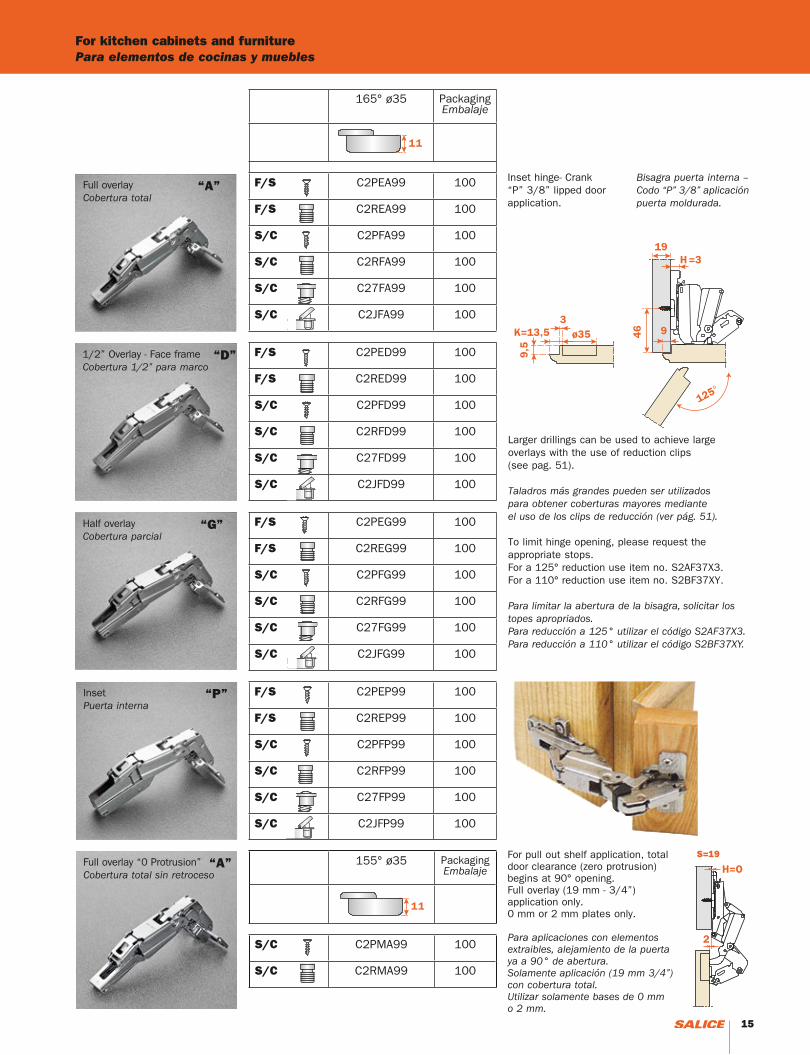
For kitchen cabinets and furniturePara elementos de cocinas y muebles
Full overlayCobertura total
1/2” Overlay - Face frameCobertura 1/2” para marco
Half overlayCobertura parcial
InsetPuerta interna
Larger drillings can be used to achieve largeoverlays with the use of reduction clips(see pag. 51).
Taladros más grandes pueden ser utilizados para obtener coberturas mayores mediante el uso de los clips de reducción (ver pág. 51).
To limit hinge opening, please request the appropriate stops. For a 125° reduction use item no. S2AF37X3.For a 110° reduction use item no. S2BF37XY.
Para limitar la abertura de la bisagra, solicitar los topes apropriados. Para reducción a 125° utilizar el código S2AF37X3.Para reducción a 110° utilizar el código S2BF37XY.
“A”
“D”
“G”
“P”
Full overlay “0 Protrusion”Cobertura total sin retroceso
“A”For pull out shelf application, total door clearance (zero protrusion) begins at 90° opening. Full overlay (19 mm - 3/4”) application only. 0 mm or 2 mm plates only.
Para aplicaciones con elementos extraibles, alejamiento de la puerta ya a 90° de abertura. Solamente aplicación (19 mm 3/4”) con cobertura total. Utilizar solamente bases de 0 mm o 2 mm.
Inset hinge- Crank “P” 3/8” lipped door application.
Bisagra puerta interna – Codo “P” 3/8” aplicación puerta moldurada.
S=19
165° ø35 PackagingEmbalaje
F/S C2PEA99 100
F/S C2REA99 100
S/C C2PFA99 100
S/C C2RFA99 100
S/C C27FA99 100
S/C C2JFA99 100
F/S C2PED99 100
F/S C2RED99 100
S/C C2PFD99 100
S/C C2RFD99 100
S/C C27FD99 100
S/C C2JFD99 100
F/S C2PEG99 100
F/S C2REG99 100
S/C C2PFG99 100
S/C C2RFG99 100
S/C C27FG99 100
S/C C2JFG99 100
F/S C2PEP99 100
F/S C2REP99 100
S/C C2PFP99 100
S/C C2RFP99 100
S/C C27FP99 100
S/C C2JFP99 100
155° ø35 PackagingEmbalaje
S/C C2PMA99 100
S/C C2RMA99 100
14 15

Series 200 - Special hinges for kitchen cabinets and furniture - positive angle hingesSerie 200 - Bisagras especiales para elementos de cocinas y muebles ángulo positivo
94° ø35 PackagingEmbalaje
S/C C2PBZ99 150
S/C C2RBZ99 150
S/C C27BZ99 150
S/C C2JBZ99 150
S/C C2PBU99 150
S/C C2RBU99 150
S/C C27BU99 150
S/C C2JBU99 150
S/C C2PBE99 150
S/C C2RBE99 150
S/C C27BE99 150
S/C C2JBE99 150
S/C C2PBT99 150
S/C C2RBT99 150
S/C C27BT99 150
S/C C2JBT99 150
S/C C2PBK99 150
S/C C2RBK99 150
S/C C27BK99 150
S/C C2JBK99 150
Corner hinge +15°Bisagra ángulo +15°
Corner hinge +24°Bisagra ángulo +24°
Corner hinge +30°Bisagra ángulo +30°
Corner hinge +30°Bisagra ángulo +30°
Corner hinge +37°Bisagra ángulo +37°
K = 3 to 9K = de 3 a 9
K = 3 to 9K = de 3 a 9
K = 3 to 9K = de 3 a 9
K = 3 to 9K = de 3 a 9
K = 3 to 9K = de 3 a 9
16 17
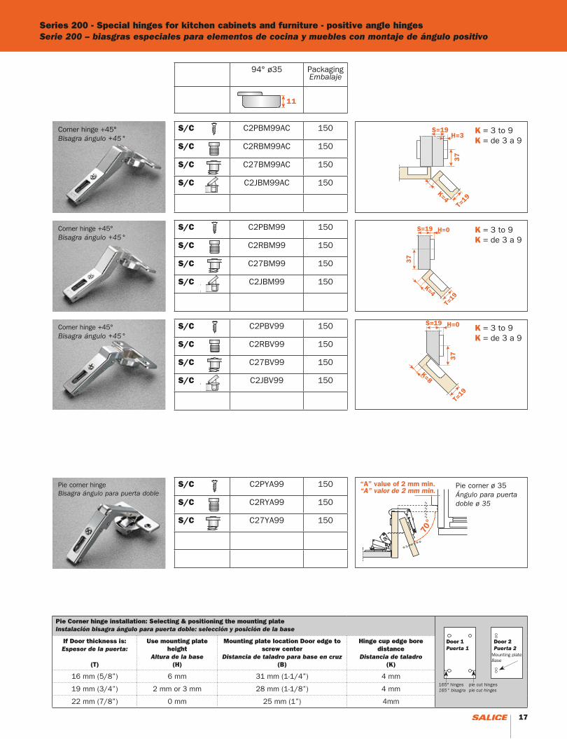
Series 200 - Special hinges for kitchen cabinets and furniture - positive angle hingesSerie 200 – biasgras especiales para elementos de cocina y muebles con montaje de ángulo positivo
Corner hinge +45°Bisagra ángulo +45°
Pie corner hingeBisagra ángulo para puerta doble
Pie corner ø 35 Ángulo para puerta doble ø 35
Pie Corner hinge installation: Selecting & positioning the mounting plateInstalación bisagra ángulo para puerta doble: selección y posición de la base
If Door thickness is:Espesor de la puerta:
(T)
Use mounting plate height
Altura de la base(H)
Mounting plate location Door edge to screw center
Distancia de taladro para base en cruz(B)
Hinge cup edge bore distance
Distancia de taladro(K)
16 mm (5/8”) 6 mm 31 mm (1-1/4”) 4 mm
19 mm (3/4”) 2 mm or 3 mm 28 mm (1-1/8”) 4 mm
22 mm (7/8”) 0 mm 25 mm (1”) 4mm
Door 1Puerta 1
165° hinges165° bisagra
pie cut hingespie cut hinges
Mounting plateBase
94° ø35 PackagingEmbalaje
S/C C2PBM99AC 150
S/C C2RBM99AC 150
S/C C27BM99AC 150
S/C C2JBM99AC 150
S/C C2PBM99 150
S/C C2RBM99 150
S/C C27BM99 150
S/C C2JBM99 150
S/C C2PBV99 150
S/C C2RBV99 150
S/C C27BV99 150
S/C C2JBV99 150
S/C C2PYA99 150
S/C C2RYA99 150
S/C C27YA99 150
Corner hinge +45°Bisagra ángulo +45°
Corner hinge +45°Bisagra ángulo +45°
Door 2Puerta 2
K = 3 to 9K = de 3 a 9
K = 3 to 9K = de 3 a 9
K = 3 to 9K = de 3 a 9
16 17
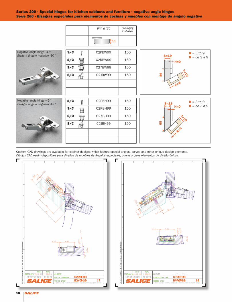
Series 200 - Special hinges for kitchen cabinets and furniture - negative angle hingesSerie 200 - Bisagras especiales para elementos de cocinas y muebles con montaje de ángulo negativo
Negative angle hinge -30°Bisagra ángulo negativo -30°
Negative angle hinge -45°Bisagra ángulo negativo -45°
94° ø 35 PackagingEmbalaje
S/C C2PBW99 150
S/C C2RBW99 150
S/C C27BW99 150
S/C C2JBW99 150
S/C C2PBH99 150
S/C C2RBH99 150
S/C C27BH99 150
S/C C2JBH99 150
K = 3 to 9K = de 3 a 9
K = 3 to 9K = de 3 a 9
Custom CAD drawings are available for cabinet designs which feature special angles, curves and other unique design elements.Dibujos CAD están disponibles para diseños de muebles de ángulos especiales, curvas y otros elementos de diseño únicos.
18 19
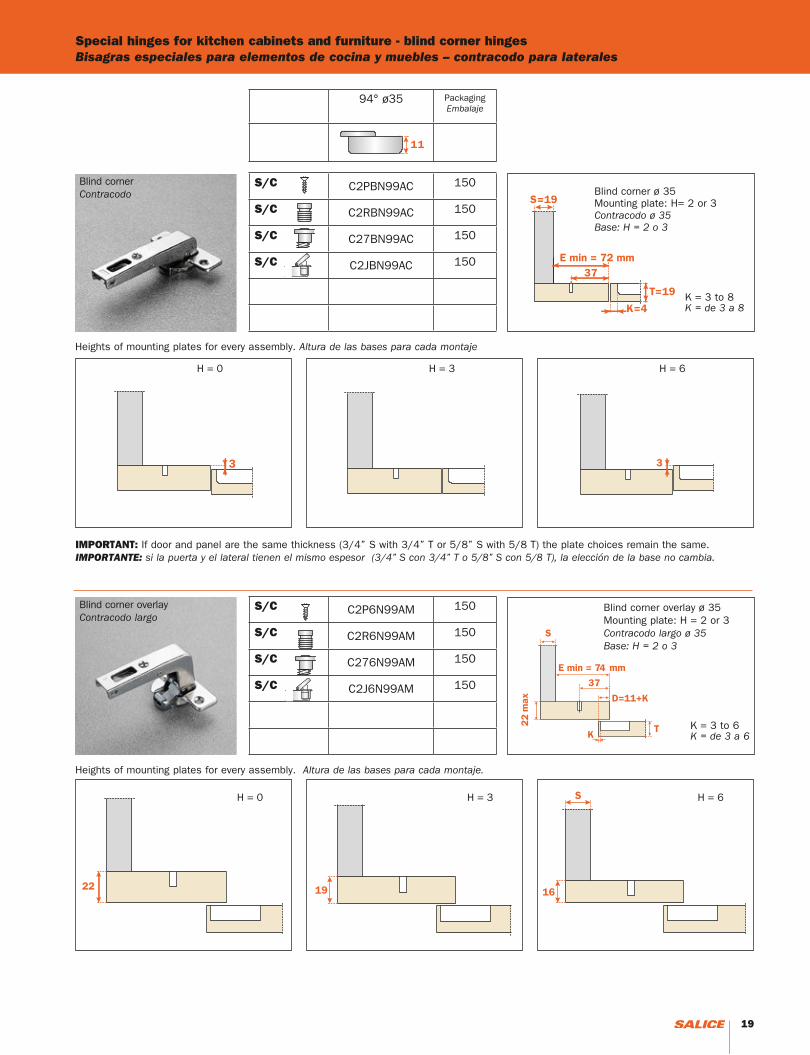
Blind corner Contracodo Blind corner ø 35
Mounting plate: H= 2 or 3Contracodo ø 35Base: H = 2 o 3
Special hinges for kitchen cabinets and furniture - blind corner hingesBisagras especiales para elementos de cocina y muebles – contracodo para laterales
Blind corner overlayContracodo largo
22
Blind corner overlay ø 35Mounting plate: H = 2 or 3Contracodo largo ø 35Base: H = 2 o 3
K = 3 to 6K = de 3 a 6
K = 3 to 8K = de 3 a 8
94° ø35 PackagingEmbalaje
S/C C2PBN99AC 150
S/C C2RBN99AC 150
S/C C27BN99AC 150
S/C C2JBN99AC 150
S/C C2P6N99AM 150
S/C C2R6N99AM 150
S/C C276N99AM 150
S/C C2J6N99AM 150
H = 0 H = 3 H = 6
Heights of mounting plates for every assembly. Altura de las bases para cada montaje
H = 0 H = 3 H = 6
Heights of mounting plates for every assembly. Altura de las bases para cada montaje.
IMPORTANT: If door and panel are the same thickness (3/4” S with 3/4” T or 5/8” S with 5/8 T) the plate choices remain the same.IMPORTANTE: si la puerta y el lateral tienen el mismo espesor (3/4” S con 3/4” T o 5/8” S con 5/8 T), la elección de la base no cambia.
18 19

For thick doors up to 32 mm (1-1/4”) 11 mm deep metal cup, possible drilling distance on the door (K); from 3 to 9 mm
For full overlay doors up to 1-1/4” thick, choose one of the following solutions, K=8 Arm “A”+ 6mm plate + adjustment - or - Arm “D”+ 0mm plate + adjustment
Para puertas de gran espesor, hasta 32 mm (1-1/4”), profundidad de la cazoleta metálica 11 mm, posibilidad de taladro de la puerta (K) desde 3 hasta 9 mm.
Para puertas de espesor hasta 1-1/4” con cobertura total, elegir una de las soluciones siguientes, K=8codo “A” + base 6 mm + regulaciónocodo “D” + base 0 mm + regulación
For inset doors: Arm “P”+ 9 mm plate + adjustment Up to 1-1/4” thick.
Para puertas internas:codo “P” + base 9 mm + regulación hasta 1-1/4” de espesor.
Series 200 - For thicker doors - 94°Serie 200 - Para puertas de gran espesor - 94°
Full overlayCobertura total
1/2” Overlay - Face frameCobertura 1/2” para marco
Half overlayCobertura parcial
InsetPuerta interna
“A”
“D”
“G”
“P”
S/C = Self-closingS/C = cierre automático
F/S = Free swingF/S = cierre libre
S2A637XF 86° Reduction clip. The reduction in the opening prevents the collision of doors against walls and other obstacles. (see pag 51)
S2A637XF 86° Tope de abertura.La reducción en abertura previene la colisión de las puertas contra paredes y otros obstáculos. (ver pàg 51)
94° ø35 PackagingEmbalaje
F/S C2PAA99 300
F/S C2RAA99 300
S/C C2PBA99 300
S/C C2RBA99 300
S/C C27BA99 300
S/C C2JBA99 300
S/C C2PBD99 300
S/C C2RBD99 300
F/S C2PAG99 300
F/S C2RAG99 300
S/C C2PBG99 300
S/C C2RBG99 300
S/C C27BG99 300
S/C C2JBG99 300
F/S C2PAP99 300
F/S C2RAP99 300
S/C C2PBP99 300
S/C C2RBP99 300
S/C C27BP99 300
S/C C2JBP99 300
20 21
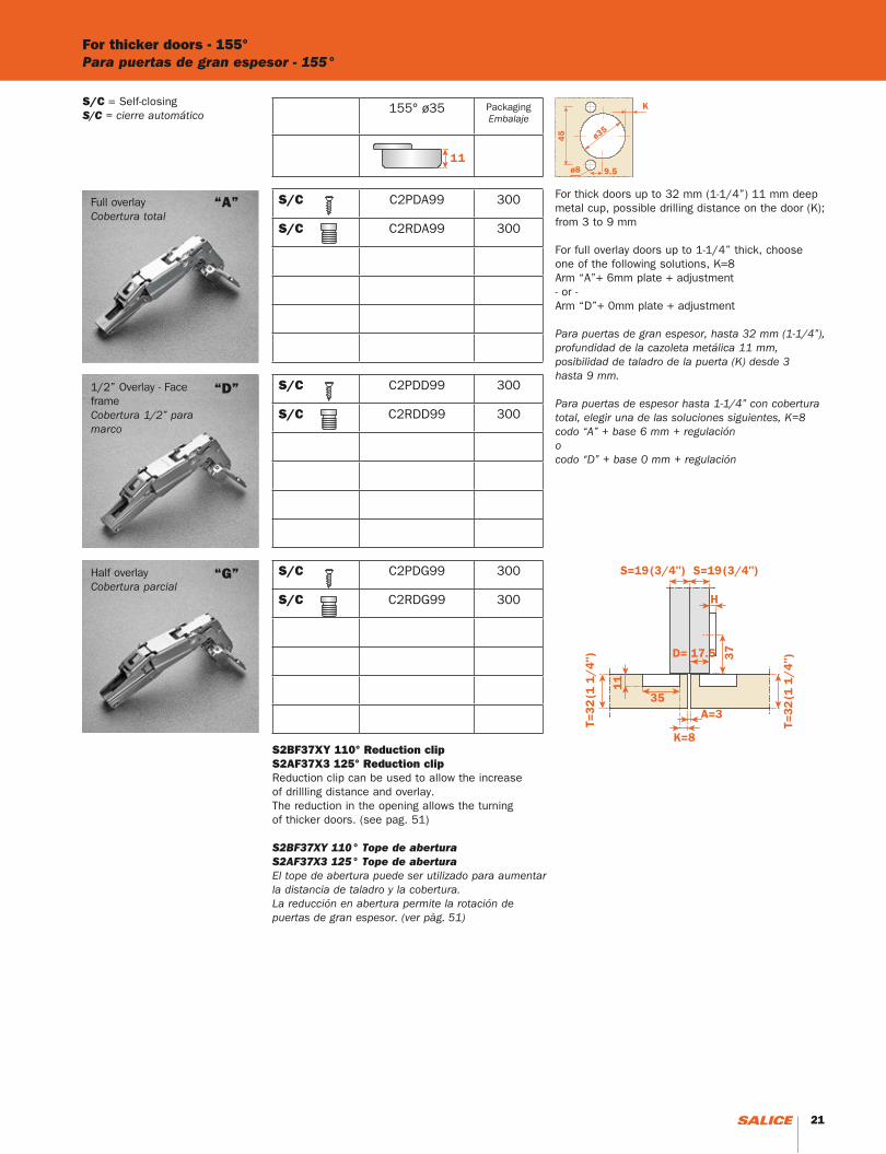
For thicker doors - 155°Para puertas de gran espesor - 155°
Full overlayCobertura total
1/2” Overlay - Face frameCobertura 1/2” para marco
Half overlayCobertura parcial
“A”
“D”
“G”
S/C = Self-closingS/C = cierre automático
S2BF37XY 110° Reduction clipS2AF37X3 125° Reduction clipReduction clip can be used to allow the increase of drillling distance and overlay.The reduction in the opening allows the turning of thicker doors. (see pag. 51)
S2BF37XY 110° Tope de abertura S2AF37X3 125° Tope de abertura El tope de abertura puede ser utilizado para aumentar la distancia de taladro y la cobertura.La reducción en abertura permite la rotación de puertas de gran espesor. (ver pàg. 51)
For thick doors up to 32 mm (1-1/4”) 11 mm deep metal cup, possible drilling distance on the door (K); from 3 to 9 mm
For full overlay doors up to 1-1/4” thick, choose one of the following solutions, K=8Arm “A”+ 6mm plate + adjustment- or -Arm “D”+ 0mm plate + adjustment
Para puertas de gran espesor, hasta 32 mm (1-1/4”), profundidad de la cazoleta metálica 11 mm, posibilidad de taladro de la puerta (K) desde 3 hasta 9 mm.
Para puertas de espesor hasta 1-1/4” con cobertura total, elegir una de las soluciones siguientes, K=8codo “A” + base 6 mm + regulaciónocodo “D” + base 0 mm + regulación
155° ø35 PackagingEmbalaje
S/C C2PDA99 300
S/C C2RDA99 300
S/C C2PDD99 300
S/C C2RDD99 300
S/C C2PDG99 300
S/C C2RDG99 300
20 21
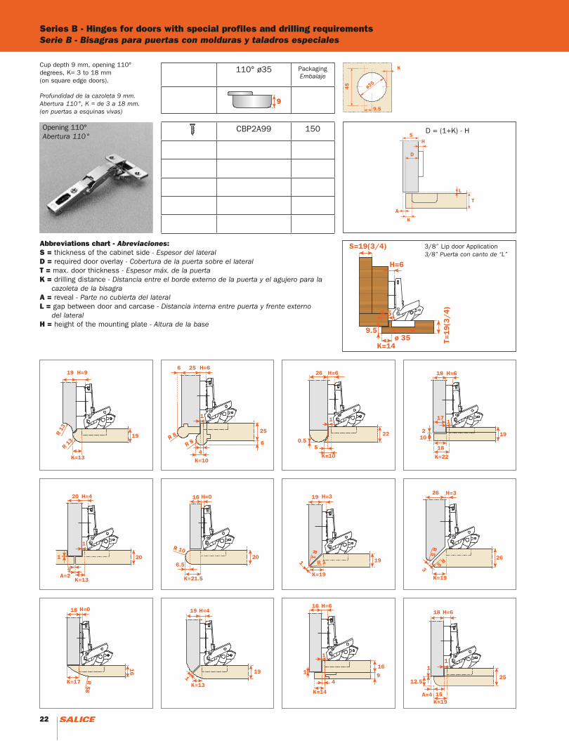
Series B - Hinges for doors with special profiles and drilling requirementsSerie B - Bisagras para puertas con molduras y taladros especiales
Opening 110°Abertura 110°
Cup depth 9 mm, opening 110° degrees, K= 3 to 18 mm (on square edge doors).
Profundidad de la cazoleta 9 mm. Abertura 110°, K = de 3 a 18 mm. (en puertas a esquinas vivas)
Abbreviations chart - Abreviaciones:S = thickness of the cabinet side - Espesor del lateralD = required door overlay - Cobertura de la puerta sobre el lateralT = max. door thickness - Espesor máx. de la puerta K = drilling distance - Distancia entre el borde externo de la puerta y el agujero para la cazoleta de la bisagraA = reveal - Parte no cubierta del lateralL = gap between door and carcase - Distancia interna entre puerta y frente externo del lateralH = height of the mounting plate - Altura de la base
D = (1+K) - H
3/8” Lip door Application3/8” Puerta con canto de “L”
110° ø35 PackagingEmbalaje
CBP2A99 150
9
22 23
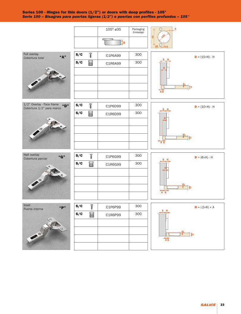
Series 100 - Hinges for thin doors (1/2”) or doors with deep profiles - 105°Serie 100 – Bisagras para puertas ligeras (1/2”) o puertas con perfiles profundos – 105°
D = (15+K) - H
D = (6+K) - H
D = (10+K) - H
H = (-2+K) + A
1/2” Overlay - Face frameCobertura 1/2” para marco
“A”
“D”
“G”
“P”
Full overlayCobertura total
Half overlayCobertura parcial
InsetPuerta interna
105° ø35 PackagingEmbalaje
S/C C1P6A99 300
S/C C1R6A99 300
S/C C1P6D99 300
S/C C1R6D99 300
S/C C1P6G99 300
S/C C1R6G99 300
S/C C1P6P99 300
S/C C1R6P99 300
22 23
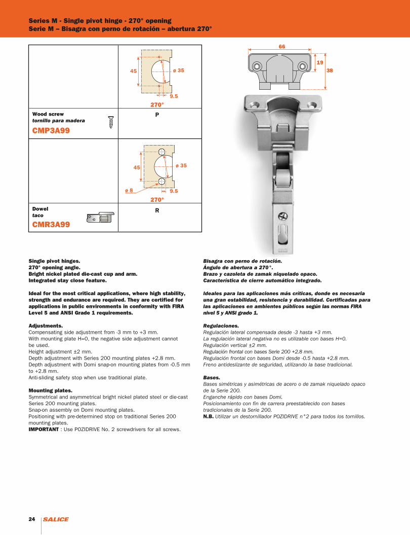
Series M - Single pivot hinge - 270° openingSerie M – Bisagra con perno de rotación – abertura 270°
Single pivot hinges.270° opening angle.Bright nickel plated die-cast cup and arm.Integrated stay close feature.
Ideal for the most critical applications, where high stability, strength and endurance are required. They are certified for applications in public environments in conformity with FIRA Level 5 and ANSI Grade 1 requirements.
Adjustments.Compensating side adjustment from -3 mm to +3 mm.With mounting plate H=0, the negative side adjustment cannot be used.Height adjustment ±2 mm.Depth adjustment with Series 200 mounting plates +2.8 mm.Depth adjustment with Domi snap-on mounting plates from -0.5 mm to +2.8 mm.Anti-sliding safety stop when use traditional plate.
Mounting plates.Symmetrical and asymmetrical bright nickel plated steel or die-cast Series 200 mounting plates.Snap-on assembly on Domi mounting plates.Positioning with pre-determined stop on traditional Series 200 mounting plates.IMPORTANT : Use POZIDRIVE No. 2 screwdrivers for all screws.
Bisagra con perno de rotación.Ángulo de abertura a 270°.Brazo y cazoleta de zamak niquelado opaco.Característica de cierre automático integrado.
Ideales para las aplicaciones más críticas, donde es necesaria una gran estabilidad, resistencia y durabilidad. Certificadas para las aplicaciones en ambientes públicos según las normas FIRA nivel 5 y ANSI grado 1.
Regulaciones.Regulación lateral compensada desde -3 hasta +3 mm.La regulación lateral negativa no es utilizable con bases H=0. Regulación vertical ±2 mm.Regulación frontal con bases Serie 200 +2.8 mm.Regulación frontal con bases Domi desde -0.5 hasta +2.8 mm.Freno antideslizante de seguridad, utilizando la base tradicional.
Bases.Bases simétricas y asimétricas de acero o de zamak niquelado opaco de la Serie 200.Enganche rápido con bases Domi.Posicionamiento con fin de carrera preestablecido con bases tradicionales de la Serie 200.N.B. Utilizar un destornillador POZIDRIVE n°2 para todos los tornillos.
Wood screwtornillo para madera
Doweltaco
CMP3A99
CMR3A99
24 25
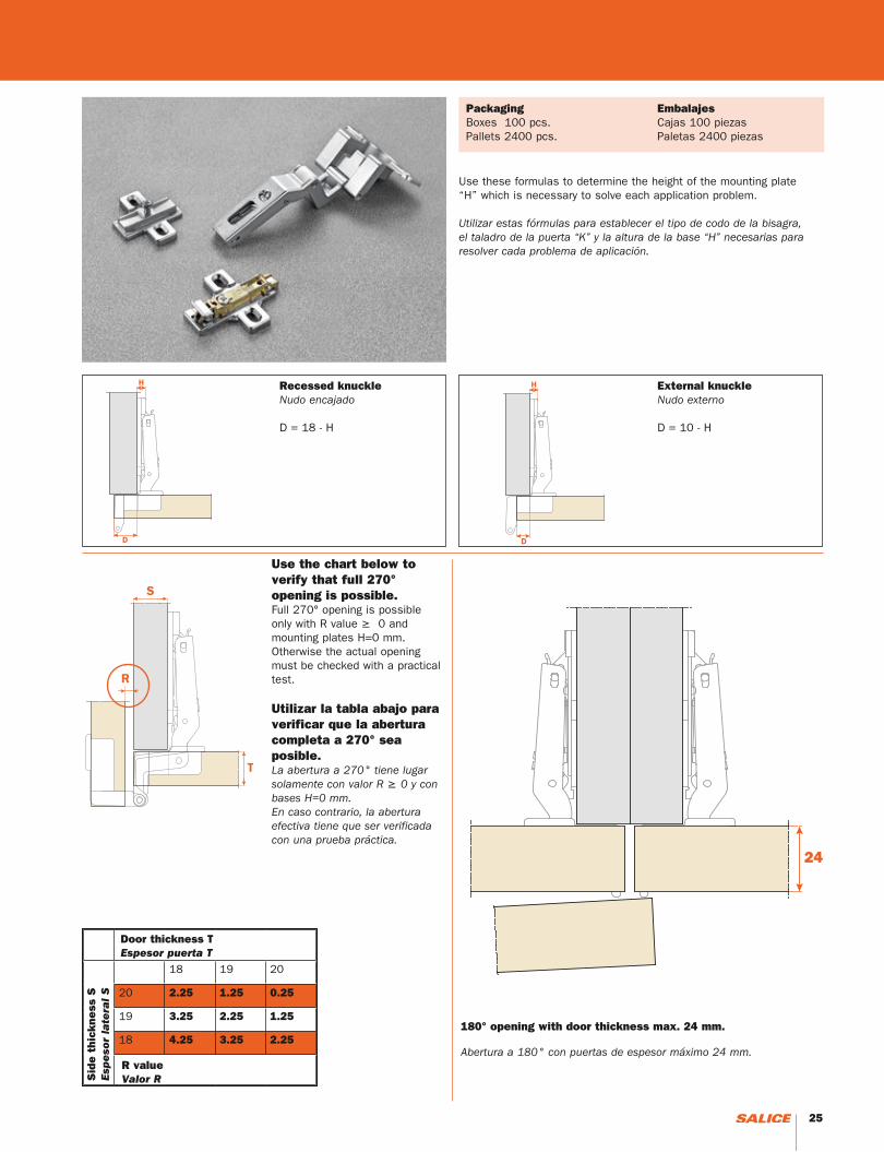
18 19 20
20 2.25 1.25 0.25
19 3.25 2.25 1.25
18 4.25 3.25 2.25180° opening with door thickness max. 24 mm.
Abertura a 180° con puertas de espesor máximo 24 mm.
Recessed knuckleNudo encajado
D = 18 - H
Use these formulas to determine the height of the mounting plate “H” which is necessary to solve each application problem.
Utilizar estas fórmulas para establecer el tipo de codo de la bisagra, el taladro de la puerta “K” y la altura de la base “H” necesarias para resolver cada problema de aplicación.
PackagingBoxes 100 pcs.Pallets 2400 pcs.
External knuckleNudo externo
D = 10 - H
Door thickness TEspesor puerta T
Use the chart below to verify that full 270° opening is possible.Full 270° opening is possible only with R value ≥ 0 and mounting plates H=0 mm.Otherwise the actual opening must be checked with a practical test.
Utilizar la tabla abajo para verificar que la abertura completa a 270° sea posible.La abertura a 270° tiene lugar solamente con valor R ≥ 0 y con bases H=0 mm. En caso contrario, la abertura efectiva tiene que ser verificada con una prueba práctica.
EmbalajesCajas 100 piezasPaletas 2400 piezas
Sid
e t
hick
ness
SEs
pe
sor
late
ral
S
R valueValor R
24 25
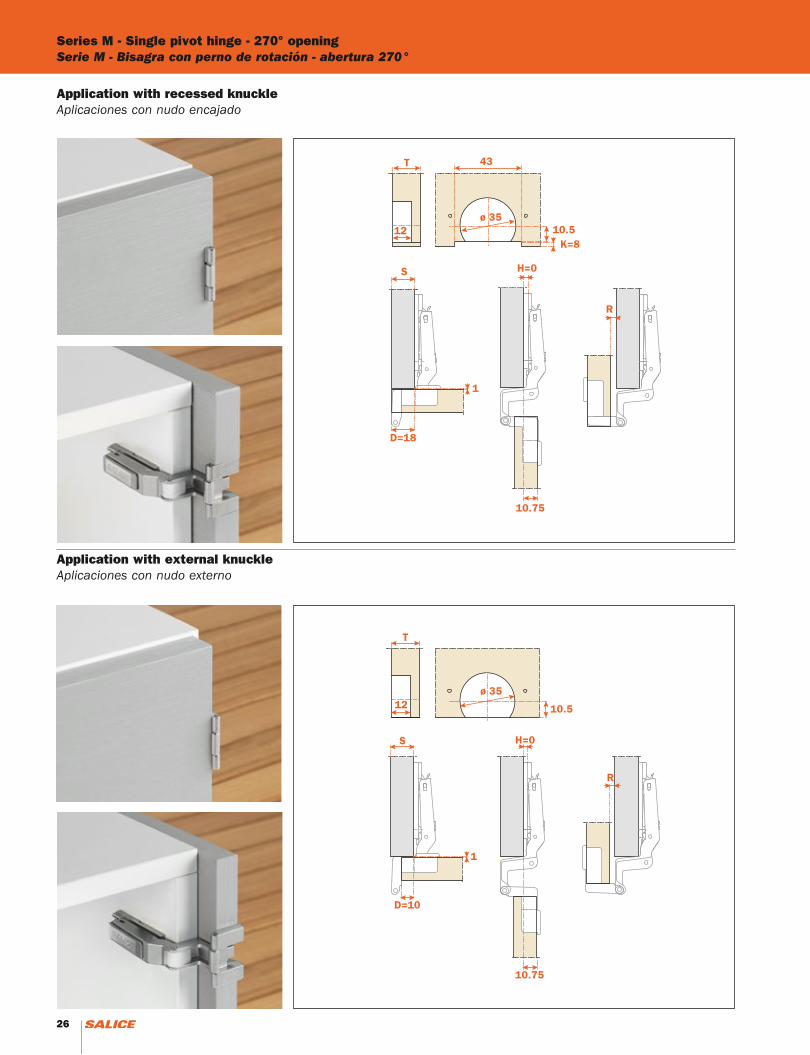
Series M - Single pivot hinge - 270° openingSerie M - Bisagra con perno de rotación - abertura 270°
Application with external knuckleAplicaciones con nudo externo
Application with recessed knuckleAplicaciones con nudo encajado
26 27
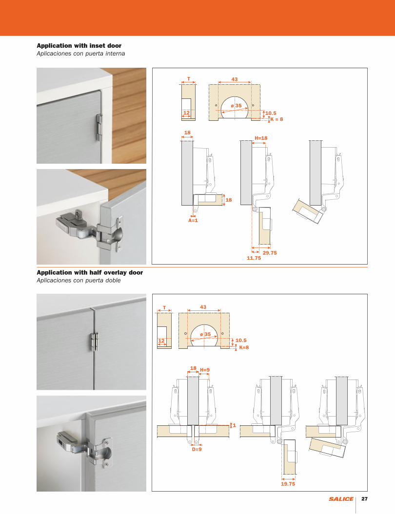
Application with inset doorAplicaciones con puerta interna
Application with half overlay doorAplicaciones con puerta doble
26 27
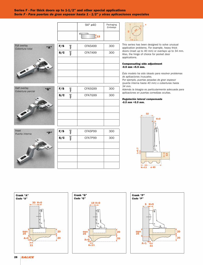
Series F - For thick doors up to 1-1/2” and other special applicationsSerie F - Para puertas de gran espesor hasta 1 - 1/2” y otras aplicaciones especiales
Full overlayCobertura total
Half overlayCobertura parcial
InsetPuerta interna
This series has been designed to solve unusual application problems. For example, heavy thick doors (inset up to 40 mm) or overlays up to 34 mm. Also, the hinge of choice for pocket door applications.
Compensating side adjustment -0.5 mm +5.5 mm.
Éste modelo ha sido ideado para resolver problemas de aplicaciones inusuales. Por ejemplo, puertas pesadas de gran espesor (puerta interna hasta 40 mm) o coberturas hasta 34 mm. Además la bisagra es particularmente adecuada para aplicaciones en puertas corredizas ocultas.
Regulación lateral compensada-0.5 mm +5.5 mm.
“A”
“P”
Crank “A”Codo “A”
Crank “G”Codo “G”
Crank “P”Codo “P”
94° ø40 PackagingEmbalaje
F/S CFA5A99 300
S/C CFA7A99 300
F/S CFA5G99 300
S/C CFA7G99 300
F/S CFA5P99 300
S/C CFA7P99 300
13
“G”
28

Overlay chartsTablas de cobertura
29
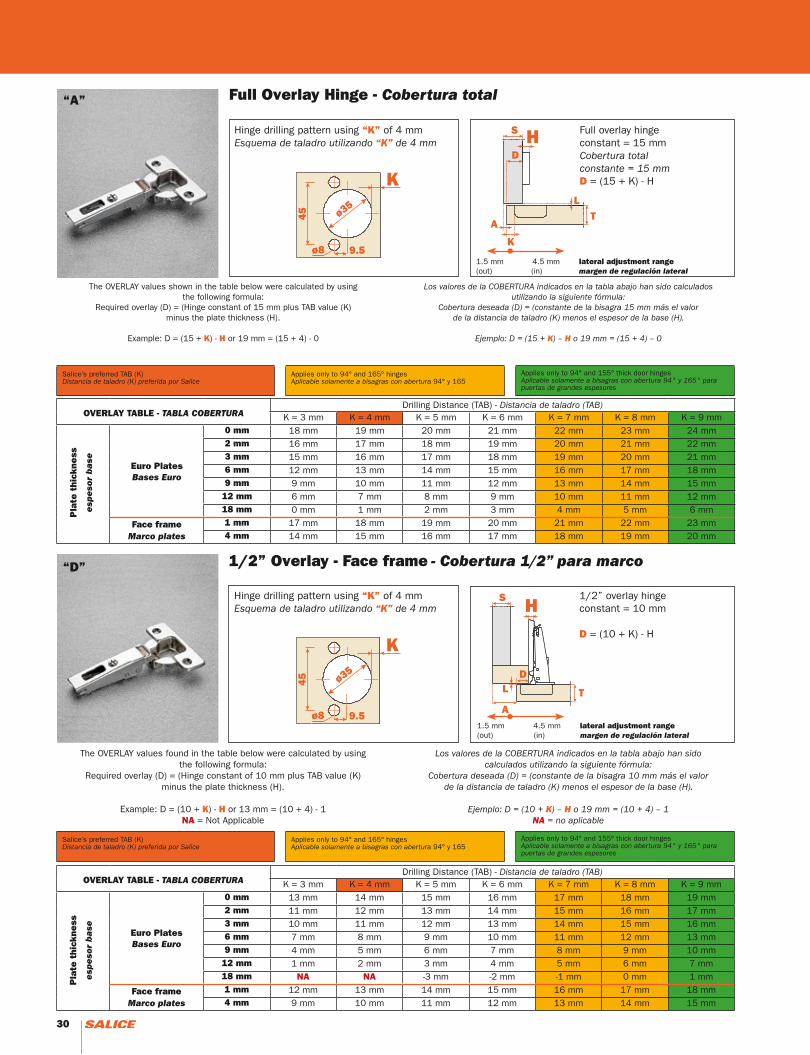
1/2” Overlay - Face frame - Cobertura 1/2” para marco
Full Overlay Hinge - Cobertura total
OVERLAY TABLE - TABLA COBERTURADrilling Distance (TAB) - Distancia de taladro (TAB)
K = 3 mm K = 4 mm K = 5 mm K = 6 mm K = 7 mm K = 8 mm K = 9 mm
Pla
te t
hick
ness
esp
eso
r b
ase
Euro PlatesBases Euro
0 mm 18 mm 19 mm 20 mm 21 mm 22 mm 23 mm 24 mm2 mm 16 mm 17 mm 18 mm 19 mm 20 mm 21 mm 22 mm3 mm 15 mm 16 mm 17 mm 18 mm 19 mm 20 mm 21 mm6 mm 12 mm 13 mm 14 mm 15 mm 16 mm 17 mm 18 mm9 mm 9 mm 10 mm 11 mm 12 mm 13 mm 14 mm 15 mm
12 mm 6 mm 7 mm 8 mm 9 mm 10 mm 11 mm 12 mm18 mm 0 mm 1 mm 2 mm 3 mm 4 mm 5 mm 6 mm
Face frame Marco plates
1 mm 17 mm 18 mm 19 mm 20 mm 21 mm 22 mm 23 mm4 mm 14 mm 15 mm 16 mm 17 mm 18 mm 19 mm 20 mm
“A”
S HD
A
K
TL
ø35
ø8 9.5
45
K
Hinge drilling pattern using “K” of 4 mmEsquema de taladro utilizando “K” de 4 mm
Full overlay hinge constant = 15 mmCobertura totalconstante = 15 mmD = (15 + K) - H
The OVERLAY values shown in the table below were calculated by using the following formula:
Required overlay (D) = (Hinge constant of 15 mm plus TAB value (K) minus the plate thickness (H).
Example: D = (15 + K) - H or 19 mm = (15 + 4) - 0
Los valores de la COBERTURA indicados en la tabla abajo han sido calculados utilizando la siguiente fórmula:
Cobertura deseada (D) = (constante de la bisagra 15 mm más el valor de la distancia de taladro (K) menos el espesor de la base (H).
Ejemplo: D = (15 + K) – H o 19 mm = (15 + 4) – 0
Salice’s preferred TAB (K)Distancia de taladro (K) preferida por Salice
Applies only to 94° and 165° hingesAplicable solamente a bisagras con abertura 94° y 165
Applies only to 94° and 155° thick door hingesAplicable solamente a bisagras con abertura 94° y 165° para puertas de grandes espesores
OVERLAY TABLE - TABLA COBERTURADrilling Distance (TAB) - Distancia de taladro (TAB)
K = 3 mm K = 4 mm K = 5 mm K = 6 mm K = 7 mm K = 8 mm K = 9 mm
Pla
te t
hick
ness
esp
eso
r b
ase Euro Plates
Bases Euro
0 mm 13 mm 14 mm 15 mm 16 mm 17 mm 18 mm 19 mm2 mm 11 mm 12 mm 13 mm 14 mm 15 mm 16 mm 17 mm3 mm 10 mm 11 mm 12 mm 13 mm 14 mm 15 mm 16 mm6 mm 7 mm 8 mm 9 mm 10 mm 11 mm 12 mm 13 mm9 mm 4 mm 5 mm 6 mm 7 mm 8 mm 9 mm 10 mm
12 mm 1 mm 2 mm 3 mm 4 mm 5 mm 6 mm 7 mm18 mm NA NA -3 mm -2 mm -1 mm 0 mm 1 mm
Face frame Marco plates
1 mm 12 mm 13 mm 14 mm 15 mm 16 mm 17 mm 18 mm4 mm 9 mm 10 mm 11 mm 12 mm 13 mm 14 mm 15 mm
1.5 mm 4.5 mm lateral adjustment range(out) (in) margen de regulación lateral
S H
A
LD
Tø35
ø8 9.5
45
K
Hinge drilling pattern using “K” of 4 mmEsquema de taladro utilizando “K” de 4 mm
1/2” overlay hinge constant = 10 mm
D = (10 + K) - H
The OVERLAY values found in the table below were calculated by using the following formula:
Required overlay (D) = (Hinge constant of 10 mm plus TAB value (K) minus the plate thickness (H).
Example: D = (10 + K) - H or 13 mm = (10 + 4) - 1NA = Not Applicable
Los valores de la COBERTURA indicados en la tabla abajo han sido calculados utilizando la siguiente fórmula:
Cobertura deseada (D) = (constante de la bisagra 10 mm más el valor de la distancia de taladro (K) menos el espesor de la base (H).
Ejemplo: D = (10 + K) – H o 19 mm = (10 + 4) – 1NA = no aplicable
1.5 mm 4.5 mm lateral adjustment range(out) (in) margen de regulación lateral
Salice’s preferred TAB (K)Distancia de taladro (K) preferida por Salice
Applies only to 94° and 165° hingesAplicable solamente a bisagras con abertura 94° y 165
Applies only to 94° and 155° thick door hingesAplicable solamente a bisagras con abertura 94° y 165° para puertas de grandes espesores
“D”
30 31

Inset - Puerta interna
Half overlay - Cobertura parcial
OVERLAY TABLE - TABLA COBERTURADrilling Distance (TAB) - Distancia de taladro (TAB)
K = 3 mm K = 4 mm K = 5 mm K = 6 mm K = 7 mm K = 8 mm K = 9 mm
Pla
te t
hick
ness
esp
eso
r b
ase Euro Plates
Bases Euro
0 mm 9 mm 10 mm 11 mm 12 mm 13 mm 14 mm 15 mm2 mm 7 mm 8 mm 9 mm 10 mm 11 mm 12 mm 13 mm3 mm 6 mm 7 mm 8 mm 9 mm 10 mm 11 mm 12 mm6 mm 3 mm 4 mm 5 mm 6 mm 7 mm 8 mm 9 mm9 mm 0 mm 1 mm 2 mm 3 mm 4 mm 5 mm 6 mm
12 mm -3 mm -2 mm -1 mm 0 mm 1 mm 2 mm 3 mm18 mm NA NA NA NA NA NA -3 mm
Face frame Marco plates
1 mm 8 mm 9 mm 10 mm 11 mm 12 mm 13 mm 14 mm4 mm 5 mm 6 mm 7 mm 8 mm 9 mm 10 mm 11 mm
ø35
ø8 9.5
45
K
Hinge drilling pattern using “K” of 4 mmEsquema de taladro utilizando “K” de 4 mm
Half overlay hinge constant = 6 mm
D = (6 + K) - H
The OVERLAY values found in the table below were calculated by using the following formula:
Required overlay (D) = (Hinge constant of 6 mm plus TAB value (K) minus the plate thickness (H).
Example: D = (6 + K) - H or 10 mm = (6 + 4) - 0NA = Not Applicable
Los valores de la COBERTURA indicados en la tabla abajo han sido calculados utilizando la siguiente fórmula:
Cobertura deseada (D) = (constante de la bisagra 6 mm más el valor de la distancia de taladro (K) menos el espesor de la base (H).
Ejemplo: D = (6 + K) – H o 10 mm = (6 + 4) – 0NA = no aplicable
1.5 mm 4.5 mm lateral adjustment range(out) (in) margen de regulación lateral
H S
D D
G GLT
AK
T
H
OVERLAY TABLE - TABLA COBERTURADrilling Distance (TAB) - Distancia de taladro (TAB)
K = 3 mm K = 4 mm K = 5 mm K = 6 mm K = 7 mm K = 8 mm K = 9 mm
Pla
te t
hick
ness
esp
eso
r b
ase Euro Plates
Bases Euro
0 mm +1 mm NA NA NA NA NA NA2 mm -1 mm 0 mm +1 mm NA NA NA NA3 mm -2 mm -1 mm 0 mm +1 mm NA NA NA6 mm NA NA -3 mm -2 mm -1 mm 0 mm +1 mm9 mm NA NA NA NA NA -3 mm -2 mm
Face frame Marco plates
NOT APPLICABLE
ø35
ø8 9.5
45
K
Inset hinge constant = -2 mmPuerta internaconstante = -2 mm
H = (-2 + K) + A
The OVERLAY values found in the table below were calculated by using the following formula:
Required plate height (H) = (Hinge constant of -2 mm plus TAB value (K) plus the “A” value (Gap).
Example: If a 1 mm gap is desired and drilling at 4mm, use the formula H = (-2 + K) + A. H = (-2 + 4) + 1 or Ht. = 3 mm.
NA = Not Applicable
Los valores de la COBERTURA indicados en la tabla abajo han sido calculadosutilizando la siguiente fórmula:
Altura base deseada (H) = (constante de la bisagra -2 mm más el valor de la distancia de taladro (K) más el valor “A” (parte no cubierta del lateral)
Ejemplo: si se requiere una parte no cubierta del lateral de 1 mm y taladro a 4 mm, utilizar la fórmula
H = (-2 + K) + A. H = (-2 +4) +1 o alt.= 3 mmNA = no aplicable
1.5 mm 4.5 mm lateral adjustment range(out) (in) margen de regulación lateral
Salice’s preferred TAB (K)Distancia de taladro (K) preferida por Salice
Applies only to 94° and 165° hingesAplicable solamente a bisagras con abertura 94° y 165
Applies only to 94° and 155° thick door hingesAplicable solamente a bisagras con abertura 94° y 165° para puertas de grandes espesores
Salice’s preferred TAB (K)Distancia de taladro (K) preferida por Salice
Applies only to 94° and 165° hingesAplicable solamente a bisagras con abertura 94° y 165
Applies only to 94° and 155° thick door hingesAplicable solamente a bisagras con abertura 94° y 165° para puertas de grandes espesores
“G”
“P”
SH
A K
T
L
30 31

32
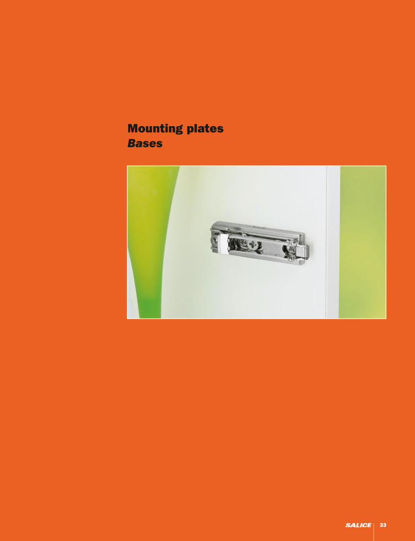
Mounting platesBases
33
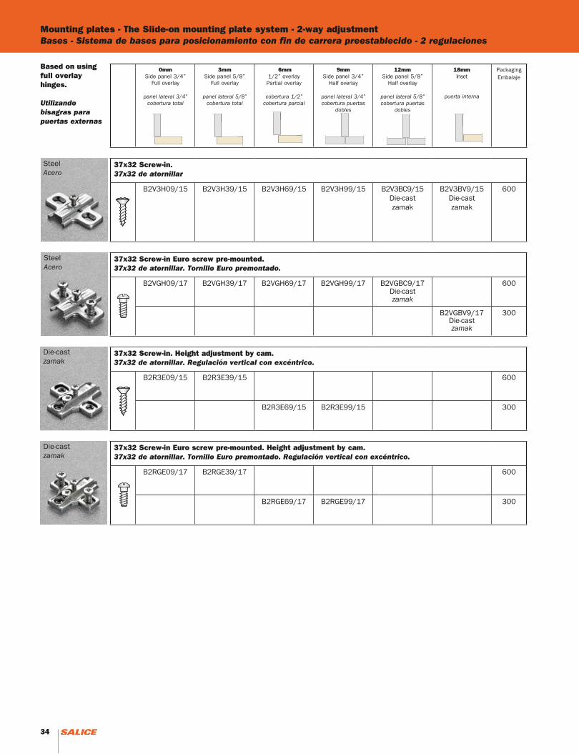
Mounting plates - The Slide-on mounting plate system - 2-way adjustmentBases - Sistema de bases para posicionamiento con fin de carrera preestablecido - 2 regulaciones
SteelAcero
SteelAcero
Die-castzamak
Die-castzamak
Based on using full overlay hinges.
Utilizando bisagras para puertas externas
0mmSide panel 3/4”
Full overlay
panel lateral 3/4”cobertura total
3mmSide panel 5/8”
Full overlay
panel lateral 5/8”cobertura total
6mm1/2” overlayPartial overlay
cobertura 1/2”cobertura parcial
9mmSide panel 3/4”
Half overlay
panel lateral 3/4”cobertura puertas
dobles
12mmSide panel 5/8”
Half overlay
panel lateral 5/8”cobertura puertas
dobles
18mmInset
puerta interna
PackagingEmbalaje
37x32 Screw-in.37x32 de atornillar
B2V3H09/15 B2V3H39/15 B2V3H69/15 B2V3H99/15 B2V3BC9/15Die-castzamak
B2V3BV9/15Die-castzamak
600
37x32 Screw-in Euro screw pre-mounted.37x32 de atornillar. Tornillo Euro premontado.
B2VGH09/17 B2VGH39/17 B2VGH69/17 B2VGH99/17 B2VGBC9/17Die-castzamak
600
B2VGBV9/17Die-castzamak
300
37x32 Screw-in. Height adjustment by cam.37x32 de atornillar. Regulación vertical con excéntrico.
B2R3E09/15 B2R3E39/15 600
B2R3E69/15 B2R3E99/15 300
37x32 Screw-in Euro screw pre-mounted. Height adjustment by cam.37x32 de atornillar. Tornillo Euro premontado. Regulación vertical con excéntrico.
B2RGE09/17 B2RGE39/17 600
B2RGE69/17 B2RGE99/17 300
34 35

The slide-on mounting plate system for special angles - 2-way adjustmentSistema de bases para posicionamiento con fin de carrera preestablecido para ángulos especiales -2 regulaciones
PackagingEmbalaje
Screw-in.De atornillar.
B2V3BW9/15 600
Screw-in.De atornillar.
B2V3BW9R/15 600
Screw-inDe atornillar.
B2V3BW9S/15 300
15°
+10° +30°
+ 7.5°
An almost infinite variety of angled door applications is possible using variable-angle mounting plates in conjunction with one of Salice’s range of angled-arm hinges.
Las bases de regulación variable, oportunadamente combinadas a los diversos codos de las bisagras, ofrecen innumerables soluciones de montajes angulares de las puertas.
SAV354X9R
SAV354X9S
Variable-angle adaptersDie-cast adapters for all mounting plates.
Adaptadores inclinadosAdaptadores de zamac combinables con todas la bases.
Die-cast adapter +5°. Fixing: wood screw ø 6x3/4”.Adaptadores de zamac +5°. Fijación: tornillo para madera ø 6x3/4.
Die-cast adapter +10°. Fixing: wood screw ø 6x1”.Adaptadores de zamac +10°. Fijación: tornillo para madera ø 6x1”.
* Can be used with straight arm plates (BAP) or wing style plates (BAV, BAR).* puede ser utilizado con bases longitudinales (BAP) o bases en cruz (BAV, BAR).
** When stacked, use wood screw ø 6x 1-1/4”.**para la fijación utilizar tornillo para madera ø 6x 1-1/4”.
*** Stacking the adapters will allow the achievement of a 15° angle.***Fijando los adaptadores se obtiene un ángulo de 15°.
Die-castZamak
Die-castZamak
Die-castZamak
-7.5°
34 35
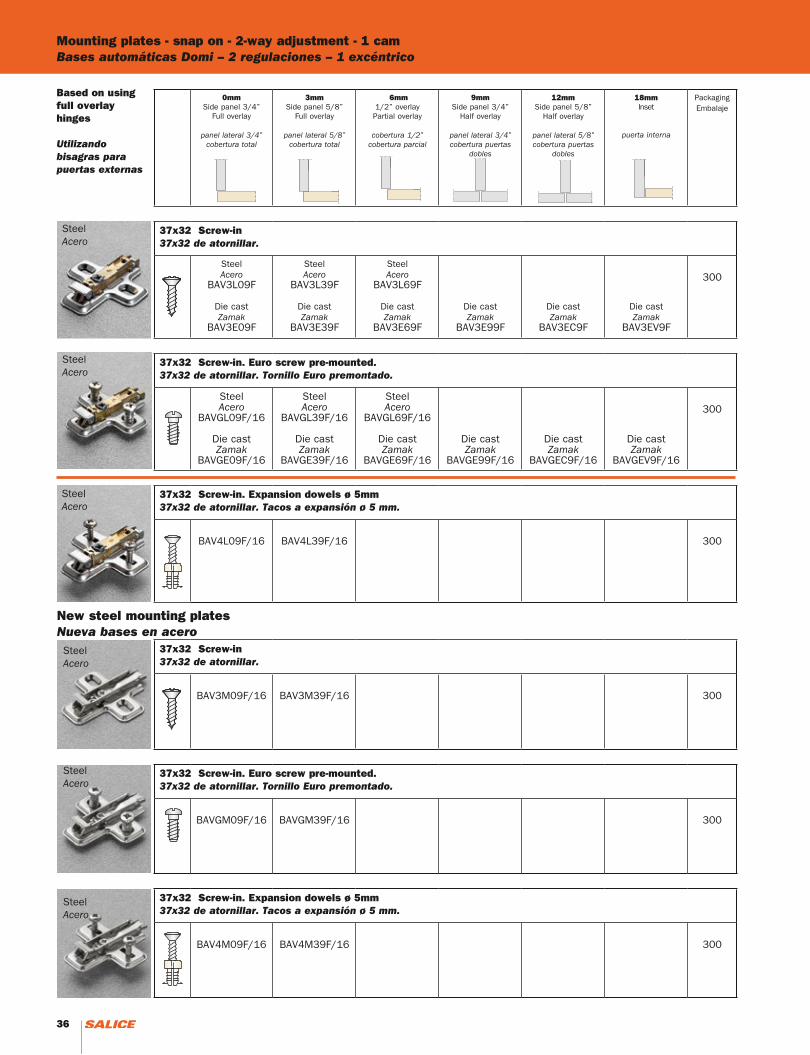
Mounting plates - snap on - 2-way adjustment - 1 camBases automáticas Domi – 2 regulaciones – 1 excéntrico
SteelAcero
SteelAcero
SteelAcero
Based on using full overlay hinges
Utilizando bisagras para puertas externas
0mmSide panel 3/4”
Full overlay
panel lateral 3/4”cobertura total
3mmSide panel 5/8”
Full overlay
panel lateral 5/8”cobertura total
6mm1/2” overlayPartial overlay
cobertura 1/2”cobertura parcial
9mmSide panel 3/4”
Half overlay
panel lateral 3/4”cobertura puertas
dobles
12mmSide panel 5/8”
Half overlay
panel lateral 5/8”cobertura puertas
dobles
18mmInset
puerta interna
PackagingEmbalaje
37x32 Screw-in37x32 de atornillar.
SteelAcero
BAV3L09F
Die castZamak
BAV3E09F
SteelAcero
BAV3L39F
Die castZamak
BAV3E39F
SteelAcero
BAV3L69F
Die castZamak
BAV3E69F
Die castZamak
BAV3E99F
Die castZamak
BAV3EC9F
Die castZamak
BAV3EV9F
300
37x32 Screw-in. Euro screw pre-mounted.37x32 de atornillar. Tornillo Euro premontado.
SteelAcero
BAVGL09F/16
Die castZamak
BAVGE09F/16
SteelAcero
BAVGL39F/16
Die castZamak
BAVGE39F/16
SteelAcero
BAVGL69F/16
Die castZamak
BAVGE69F/16
Die castZamak
BAVGE99F/16
Die castZamak
BAVGEC9F/16
Die castZamak
BAVGEV9F/16
300
37x32 Screw-in. Expansion dowels ø 5mm37x32 de atornillar. Tacos a expansión ø 5 mm.
BAV4L09F/16 BAV4L39F/16 300
37x32 Screw-in37x32 de atornillar.
BAV3M09F/16 BAV3M39F/16 300
37x32 Screw-in. Euro screw pre-mounted.37x32 de atornillar. Tornillo Euro premontado.
BAVGM09F/16 BAVGM39F/16 300
37x32 Screw-in. Expansion dowels ø 5mm37x32 de atornillar. Tacos a expansión ø 5 mm.
BAV4M09F/16 BAV4M39F/16 300
SteelAcero
SteelAcero
SteelAcero
New steel mounting platesNueva bases en acero
36 37
Mounting plates - snap on - 2-way adjustment - 2 camsBases automáticas Domi – 2 regulaciones – 2 excéntricos
0mmSide panel 3/4”
Full overlay
panel lateral 3/4”cobertura total
3mmSide panel 5/8”
Full overlay
panel lateral 5/8”cobertura total
6mm1/2” overlayPartial overlay
cobertura 1/2”cobertura parcial
PackagingEmbalaje
37x32 Screw-in # 6x5/8” - # 2 Phillips.37x32 de atornillar # 6 x 5/8” - # 2 Phillips.
BAR3L09F BAR3L39F BAR3L69F 300
37x32 Screw-in. Euro-screw pre-mounted.37x32 de atornillar. Tornillo Euro premontado.
BARGL09F/16 BARGL39F/16 BARGL69F/16 300
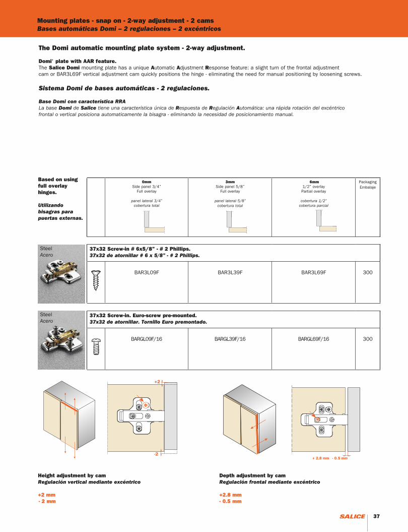
The Domi automatic mounting plate system - 2-way adjustment.
Domi® plate with AAR feature.The Salice Domi mounting plate has a unique Automatic Adjustment Response feature: a slight turn of the frontal adjustmentcam or BAR3L69F vertical adjustment cam quickly positions the hinge - eliminating the need for manual positioning by loosening screws.
Sistema Domi de bases automáticas - 2 regulaciones.
Base Domi con característica RRALa base Domi de Salice tiene una característica única de Respuesta de Regulación Automática: una rápida rotación del excéntricofrontal o vertical posiciona automaticamente la bisagra - eliminando la necesidad de posicionamiento manual.
Based on using full overlay hinges.
Utilizando bisagras para puertas externas.
SteelAcero
SteelAcero
Height adjustment by camRegulación vertical mediante excéntrico
+2 mm - 2 mm
Depth adjustment by camRegulación frontal mediante excéntrico
+2.8 mm- 0.5 mm
36 37
Mounting plates - snap on - 2-way adjustment - 2 camsBases automáticas Domi – 2 regulaciones – 2 excéntricos
0mmSide panel 3/4”
Full overlay
panel lateral 3/4”cobertura total
2mmSide panel 3/4”11/16” overlay
panel lateral 5/8”cobertura 11/16”
3mmSide panel 5/8”
Full overlay
panel lateral 5/8”cobertura total
6mm1/2” overlayPartial overlay
cobertura 1/2”cobertura parcial
9mmSide panel 3/4”
Half overlay
panel lateral 3/4”cobertura puertas
dobles
12mmSide panel 5/8”
Half overlay
panel lateral 5/8”cobertura puertas
dobles
PackagingEmbalaje
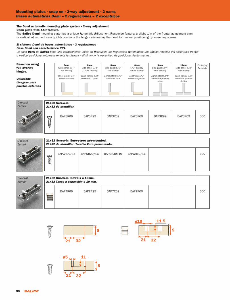
21+32 Screw-in. 21+32 de atornillar.
BAP3R09 BAP3R29 BAP3R39 BAP3R69 BAP3R99 BAP3RC9 300
21+32 Screw-in. Euro-screw pre-mounted.21+32 de atornillar. Tornillo Euro premontado.
BAPGR09/16 BAPGR29/16 BAPGR39/16 BAPGR69/16 300
21+32 Knock-in. Dowels ø 10mm.21+32 Tacos a expansión ø 10 mm.
BAP7R09 BAP7R29 BAP7R39 BAP7R69 300
The Domi automatic mounting plate system - 2-way adjustmentDomi plate with AAR feature.The Salice Domi mounting plate has a unique Automatic Adjustment Response feature: a slight turn of the frontal adjustment cam or vertical adjustment cam quickly positions the hinge - eliminating the need for manual positioning by loosening screws.
El sistema Domi de bases automáticas - 2 regulaciones Base Domi con característica RRALa base Domi de Salice tiene una característica única de Respuesta de Regulación Automática: una rápida rotación del excéntrico frontalo vertical posiciona automaticamente la bisagra - eliminando la necesidad de posicionamiento manual.
Die-castZamak
Die-castZamak
Based on using full overlay hinges.
Utilizando bisagras para puertas externas
Die-castZamak
38 39
Die-castZamak
Die-castZamak
Die-castZamak
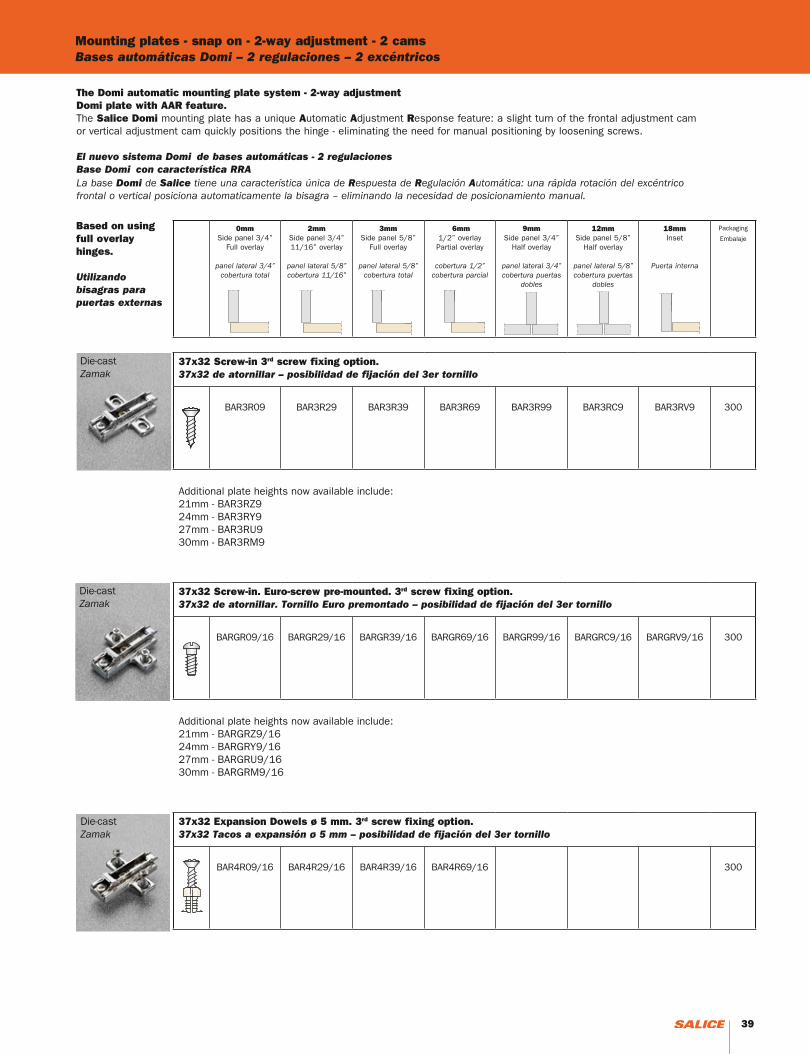
The Domi automatic mounting plate system - 2-way adjustmentDomi plate with AAR feature.The Salice Domi mounting plate has a unique Automatic Adjustment Response feature: a slight turn of the frontal adjustment cam or vertical adjustment cam quickly positions the hinge - eliminating the need for manual positioning by loosening screws.
El nuevo sistema Domi de bases automáticas - 2 regulaciones Base Domi con característica RRALa base Domi de Salice tiene una característica única de Respuesta de Regulación Automática: una rápida rotación del excéntrico frontal o vertical posiciona automaticamente la bisagra – eliminando la necesidad de posicionamiento manual.
Based on using full overlay hinges.
Utilizando bisagras para puertas externas
0mmSide panel 3/4”
Full overlay
panel lateral 3/4”cobertura total
2mmSide panel 3/4”11/16” overlay
panel lateral 5/8”cobertura 11/16”
3mmSide panel 5/8”
Full overlay
panel lateral 5/8”cobertura total
6mm1/2” overlayPartial overlay
cobertura 1/2”cobertura parcial
9mmSide panel 3/4”
Half overlay
panel lateral 3/4”cobertura puertas
dobles
12mmSide panel 5/8”
Half overlay
panel lateral 5/8”cobertura puertas
dobles
18mmInset
Puerta interna
Packaging
Embalaje
37x32 Screw-in 3rd screw fixing option. 37x32 de atornillar – posibilidad de fijación del 3er tornillo
BAR3R09 BAR3R29 BAR3R39 BAR3R69 BAR3R99 BAR3RC9 BAR3RV9 300
Additional plate heights now available include:21mm - BAR3RZ924mm - BAR3RY927mm - BAR3RU930mm - BAR3RM9
37x32 Screw-in. Euro-screw pre-mounted. 3rd screw fixing option.37x32 de atornillar. Tornillo Euro premontado – posibilidad de fijación del 3er tornillo
BARGR09/16 BARGR29/16 BARGR39/16 BARGR69/16 BARGR99/16 BARGRC9/16 BARGRV9/16 300
Additional plate heights now available include:21mm - BARGRZ9/1624mm - BARGRY9/1627mm - BARGRU9/1630mm - BARGRM9/16
37x32 Expansion Dowels ø 5 mm. 3rd screw fixing option.37x32 Tacos a expansión ø 5 mm – posibilidad de fijación del 3er tornillo
BAR4R09/16 BAR4R29/16 BAR4R39/16 BAR4R69/16 300
Mounting plates - snap on - 2-way adjustment - 2 camsBases automáticas Domi – 2 regulaciones – 2 excéntricos
38 39
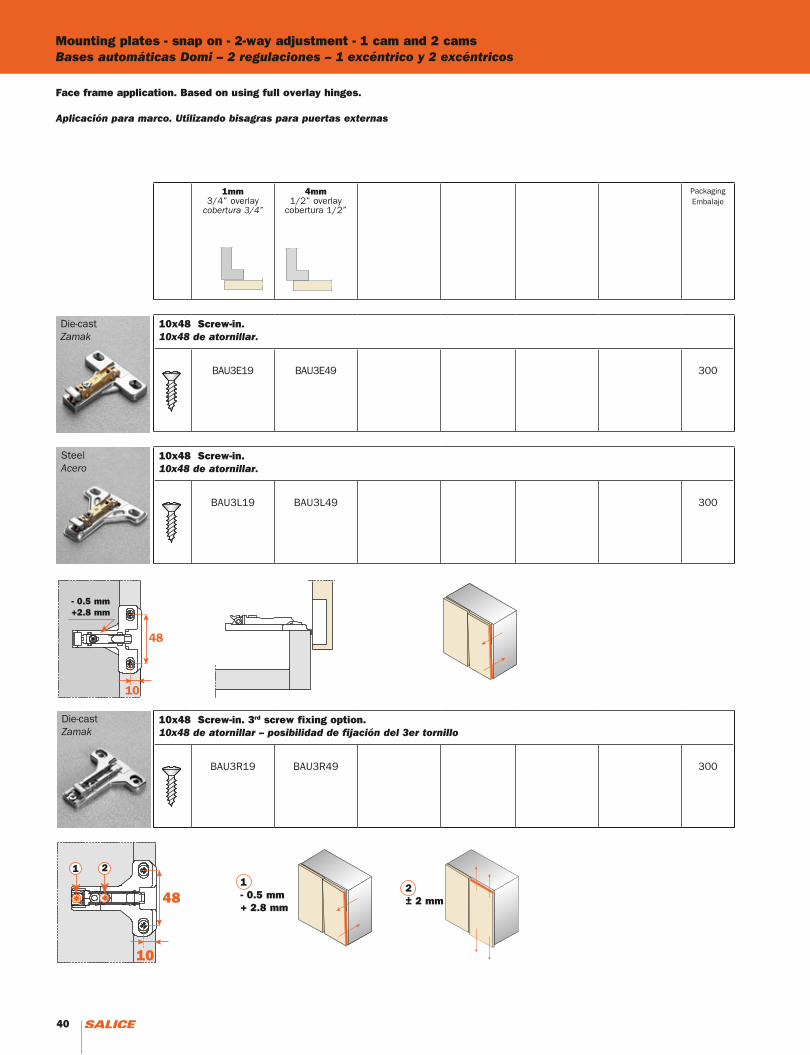
1mm3/4” overlay
cobertura 3/4”
4mm1/2” overlay
cobertura 1/2”
PackagingEmbalaje
10x48 Screw-in. 10x48 de atornillar.
BAU3E19 BAU3E49 300
10x48 Screw-in. 10x48 de atornillar.
BAU3L19 BAU3L49 300
10x48 Screw-in. 3rd screw fixing option. 10x48 de atornillar – posibilidad de fijación del 3er tornillo
BAU3R19 BAU3R49 300
Mounting plates - snap on - 2-way adjustment - 1 cam and 2 camsBases automáticas Domi – 2 regulaciones – 1 excéntrico y 2 excéntricos
Die-castZamak
SteelAcero
Die-castZamak
Face frame application. Based on using full overlay hinges.
Aplicación para marco. Utilizando bisagras para puertas externas
1- 0.5 mm+ 2.8 mm
2± 2 mm
- 0.5 mm+2.8 mm
40
Mounting plates - snap on - 2-way adjustment - 2 camsBases automáticas Domi – 2 regulaciones – 2 excéntricos
Die-castZamak
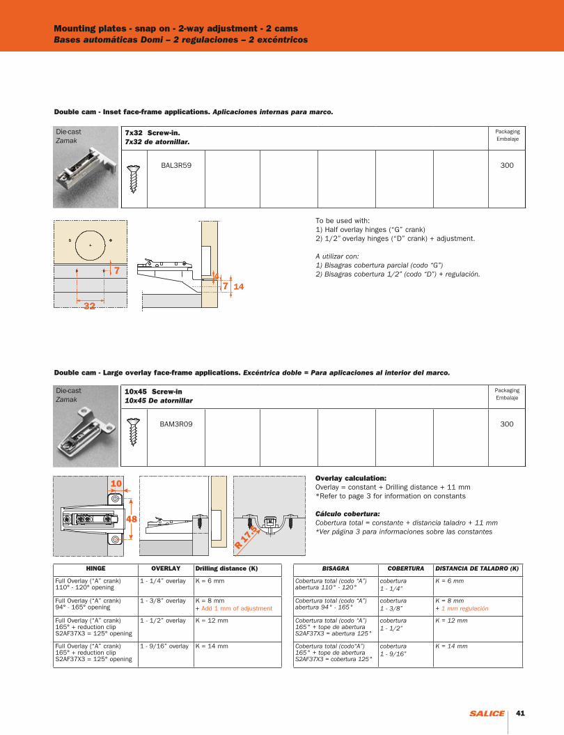
Double cam - Inset face-frame applications. Aplicaciones internas para marco.
Die-castZamak
Double cam - Large overlay face-frame applications. Excéntrica doble = Para aplicaciones al interior del marco.
To be used with:1) Half overlay hinges (“G” crank) 2) 1/2” overlay hinges (“D” crank) + adjustment.
A utilizar con:1) Bisagras cobertura parcial (codo “G”) 2) Bisagras cobertura 1/2” (codo “D”) + regulación.
HINGE OVERLAY Drilling distance (K)
Full Overlay (“A” crank)110° - 120° opening
1 - 1/4” overlay K = 6 mm
Full Overlay (“A” crank)94° - 165° opening
1 - 3/8” overlay K = 8 mm + Add 1 mm of adjustment
Full Overlay (“A” crank)165° + reduction clip S2AF37X3 = 125° opening
1 - 1/2” overlay K = 12 mm
Full Overlay (“A” crank)165° + reduction clip S2AF37X3 = 125° opening
1 - 9/16” overlay K = 14 mm
BISAGRA COBERTURA DISTANCIA DE TALADRO (K)
Cobertura total (codo “A”)abertura 110° - 120°
cobertura 1 - 1/4”
K = 6 mm
Cobertura total (codo “A”)abertura 94° - 165°
cobertura 1 - 3/8”
K = 8 mm + 1 mm regulación
Cobertura total (codo “A”)165° + tope de aberturaS2AF37X3 = abertura 125°
cobertura1 - 1/2”
K = 12 mm
Cobertura total (codo“A”)165° + tope de aberturaS2AF37X3 = cobertura 125°
cobertura 1 - 9/16”
K = 14 mm
Overlay calculation:Overlay = constant + Drilling distance + 11 mm*Refer to page 3 for information on constants
Cálculo cobertura:Cobertura total = constante + distancia taladro + 11 mm*Ver página 3 para informaciones sobre las constantes
10x45 Screw-in10x45 De atornillar
BAM3R09 300
PackagingEmbalaje
7x32 Screw-in. 7x32 de atornillar.
BAL3R59 300
PackagingEmbalaje
41
Mounting plates - snap on - 2-way adjustment - 2 camsBases automáticas Domi – 2 regulaciones – 2 excéntricos
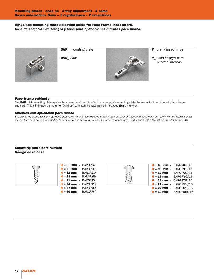
BAR_ mounting plate
BAR_ Base
P_ crank inset hinge
P_ codo bisagra para puertas internas
Hinge and mounting plate selection guide for Face Frame Inset doors.Guía de selección de bisagra y base para aplicaciones internas para marco.
Face frame cabinetsThe BAR thick mounting plate system has been developed to offer the appropriate mounting plate thickness for inset door with face framecabinets. This eliminates the need to “build up” to match the face frame interspace (IS) dimension.
Muebles con aplicación para marcoEl sistema de bases BAR con grandes espesores ha sido desarrollado para ofrecer el espesor adecuado de la base con aplicaciones internas para marco. Esto elimina la necesidad de “incrementar” para nivelar la dimensión correspondiente a la distancia entre lateral y borde del marco. (IS)
H = 6 mm - BAR3R69H = 9 mm - BAR3R99H = 12 mm - BAR3RC9H = 18 mm - BAR3RV9H = 21 mm - BAR3RZ9H = 24 mm - BAR3RY9H = 27 mm - BAR3RU9H = 30 mm - BAR3RM9
H = 6 mm - BARGR69/16H = 9 mm - BARGR99/16H = 12 mm - BARGRC9/16H = 18 mm - BARGRV9/16H = 21 mm - BARGRZ9/16H = 24 mm - BARGRY9/16H = 27 mm - BARGRU9/16H = 30 mm - BARGRM9/16
Mounting plate part numberCódigo de la base
42
Legenda
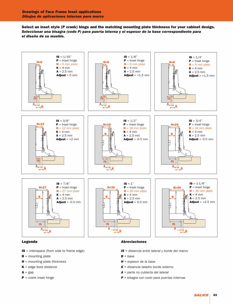
IS = interspace (from side to frame edge)
B = mounting plate
H = mounting plate thickness
K = edge bore distance
A = gap
P = crank inset hinge
Abreviaciones
IS = distancia entre lateral y borde del marco
B = base
H = espesor de la base
K = distancia taladro borde externo
A = parte no cubierta del lateral
P = bisagra con codo para puertas internas
43
Select an inset style (P crank) hinge and the matching mounting plate thickness for your cabinet design.Seleccionar una bisagra (codo P) para puerta interna y el espesor de la base correspondiente para el diseño de su mueble.
H=9
IS
AK
H=6
IS
AK
H=18
B
IS
AK
H=12
IS
AK
H=24
B
IS
AK
H=30
B
IS
AK
H=27
B
IS
AK
IS = 1/16”P = Inset hingeH = 6 mm plateK = 4 mmA = 2.5 mmAdjust = 0 mm
IS = 1/8”P = Inset hingeH = 6 mm plateK = 4 mmA = 2.5 mmAdjust = +1.5 mm
H=6
IS
AK
IS = 1/4”P = Inset hingeH = 9 mm plateK = 4 mmA = 2.5 mmAdjust = +1.5 mm
IS = 3/8”P = Inset hingeH = 12 mm plateK = 4 mmA = 2.5 mmAdjust = +2 mm
IS = 1/2”P = Inset hingeH = 18 mm plateK = 4 mmA = 2.5 mmAdjust = -0.5 mm
IS = 3/4”P = Inset hingeH = 24 mm plateK = 4 mmA = 2.5 mmAdjust = -0.5 mm
IS = 7/8”P = Inset hingeH = 27 mm plateK = 4 mmA = 2.5 mmAdjust = -0.5 mm
IS = 1”P = Inset hingeH = 30 mm plateK = 4 mmA = 2.5 mmAdjust = 0.0 mm
H=30
B
IS
AK
IS = 1-1/8”P = Inset hingeH = 30 mm plateK = 4 mmA = 2.5 mmAdjust = +2.5 mm
Drawings of Face Frame Inset applicationsDibujos de aplicaciones internas para marco

44
45
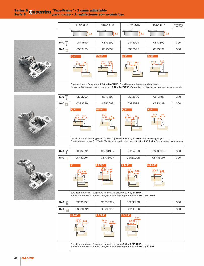
Series S “Face-Frame” - 2 cams adjustableSerie S para marco – 2 regulaciones con excéntricas
106° ø35 106° ø35 106° ø35 106° ø35 PackagingEmbalaje
S/C CSP3Y99 CSP3Z99 CSP3999 CSP3899 300
S/C CSR3Y99 CSR3Z99 CSR3999 CSR3899 300
Suggested frame fixing screw # 10 x 3/4” RHP - For all hinges with pre-assembled spacer.Tornillo de fijación aconsejado para marco # 10 x 3/4” RHP - Para todas las bisagras con distanciador premontado.
S/C CSP3799 CSP3699 CSP3599 CSP3499 300
S/C CSR3799 CSR3699 CSR3599 CSR3499 300
Zero-door protrusion - Suggested frame fixing screw # 10 x 3/4” RHP - For remaining hinges.Puerta sin retroceso - Tornillo de fijación aconsejado para marco # 10 x 3/4” RHP - Para las bisagras restantes.
S/C CSP3299N CSP3199N CSP3A99N CSP3B99N 300
S/C CSR3299N CSR3199N CSR3A99N CSR3B99N 300
Zero-door protrusion - Suggested frame fixing screw # 10 x 3/4” RHP. Puerta sin retroceso - Tornillo de fijación aconsejado para marco # 10 x 3/4” RHP.
S/C CSP3C99N CSP3D99N CSP3E99N 300
S/C CSR3C99N CSR3D99N CSR3E99N 300
Zero-door protrusion - Suggested frame fixing screw # 10 x 3/4” RHP.Puerta sin retroceso - Tornillo de fijación aconsejado para marco # 10 x 3/4” RHP.
1/4” 5/16” 3/8” 7/16”
1/2” 9/16” 5/8” 3/4”
1 1/4” 1 5/16”
1 3/8” 1 7/16”
1 1/8”
1 9/16”
CSP3E99N
CSP3E99NR
1”
46
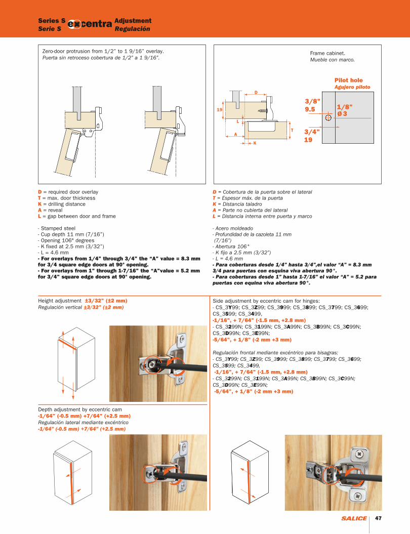
Frame cabinet.Mueble con marco.
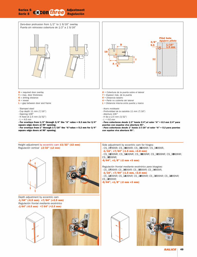
D = required door overlayT = max. door thicknessK = drilling distanceA = revealL = gap between door and frame
- Stamped steel- Cup depth 11 mm (7/16”)- Opening 106° degrees- K fixed at 2.5 mm (3/32”)- L = 4.6 mm- For overlays from 1/4” through 3/4” the “A” value = 8.3 mm for 3/4 square edge doors at 90° opening.- For overlays from 1” through 1-7/16” the “A”value = 5.2 mm for 3/4” square edge doors at 90° opening.
D = Cobertura de la puerta sobre el lateralT = Espesor máx. de la puertaK = Distancia taladroA = Parte no cubierta del lateralL = Distancia interna entre puerta y marco
- Acero moldeado - Profundidad de la cazoleta 11 mm (7/16”)- Abertura 106°- K fijo a 2.5 mm (3/32”) - L = 4.6 mm- Para coberturas desde 1/4” hasta 3/4”,el valor “A” = 8.3 mm 3/4 para puertas con esquina viva abertura 90°.- Para coberturas desde 1” hasta 1-7/16” el valor “A” = 5.2 para puertas con equina viva abertura 90°.
Zero-door protrusion from 1/2” to 1 9/16” overlay.Puerta sin retroceso cobertura de 1/2” a 1 9/16”.
Pilot holeAgujero piloto
Height adjustment ±3/32” (±2 mm) Regulación vertical ±3/32” (±2 mm)
Depth adjustment by eccentric cam -1/64” (-0.5 mm) +7/64” (+2.5 mm)Regulación lateral mediante excéntrico -1/64” (-0.5 mm) +7/64” (+2.5 mm)
Side adjustment by eccentric cam for hinges:- CS_3Y99; CS_3Z99; CS_3999; CS_3899; CS_3799; CS_3699; CS_3599; CS_3499,-1/16”, + 7/64” (-1.5 mm, +2.8 mm)- CS_3299N; CS_3199N; CS_3A99N; CS_3B99N; CS_3C99N; CS_3D99N; CS_3E99N;-5/64”, + 1/8” (-2 mm +3 mm)
Regulación frontal mediante excéntrico para bisagras:- CS_3Y99; CS_3Z99; CS_3999; CS_3899; CS_3799; CS_3699; CS_3599; CS_3499, -1/16”, + 7/64” (-1.5 mm, +2.8 mm)- CS_3299N; CS_3199N; CS_3A99N; CS_3B99N; CS_3C99N; CS_3D99N; CS_3E99N; -5/64”, + 1/8” (-2 mm +3 mm)
Series S AdjustmentSerie S Regulación
47
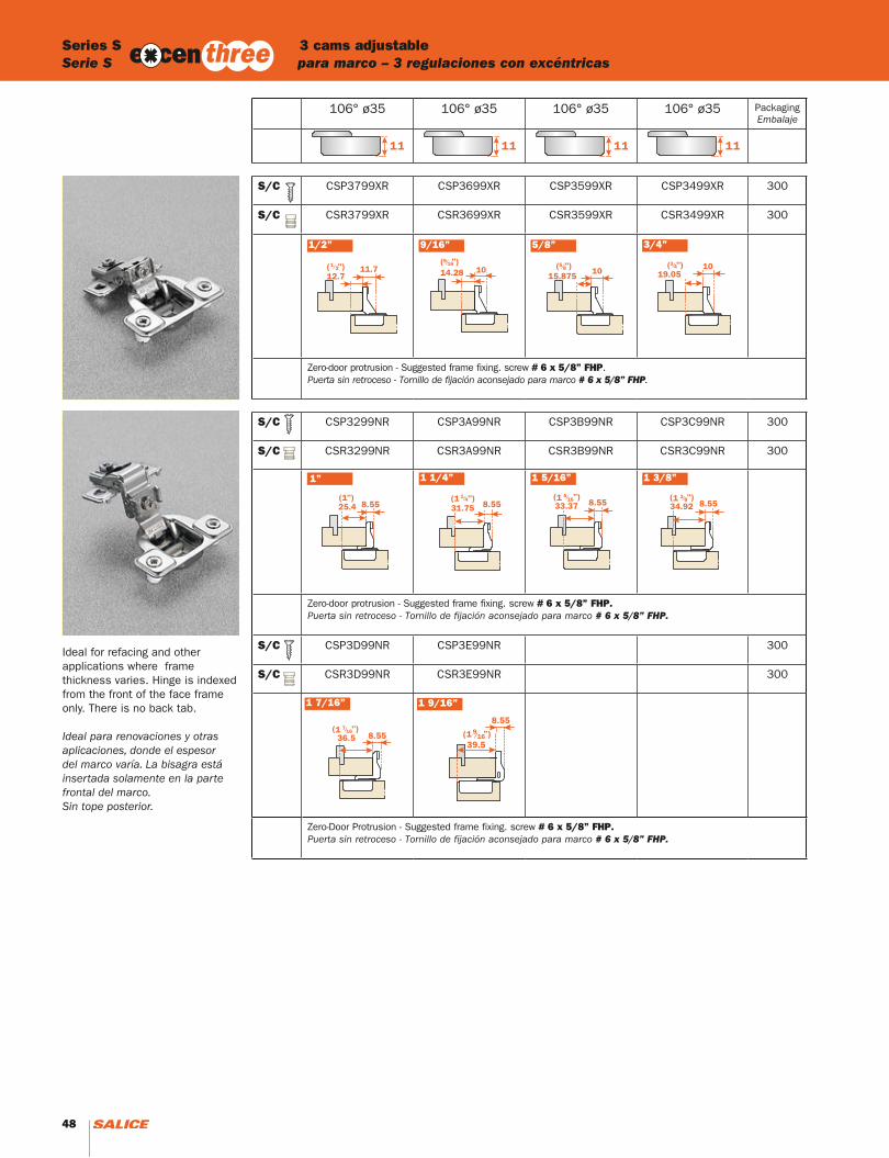
106° ø35 106° ø35 106° ø35 106° ø35 PackagingEmbalaje
S/C CSP3799XR CSP3699XR CSP3599XR CSP3499XR 300
S/C CSR3799XR CSR3699XR CSR3599XR CSR3499XR 300
Zero-door protrusion - Suggested frame fixing. screw # 6 x 5/8” FHP.Puerta sin retroceso - Tornillo de fijación aconsejado para marco # 6 x 5/8” FHP.
S/C CSP3299NR CSP3A99NR CSP3B99NR CSP3C99NR 300
S/C CSR3299NR CSR3A99NR CSR3B99NR CSR3C99NR 300
Zero-door protrusion - Suggested frame fixing. screw # 6 x 5/8” FHP. Puerta sin retroceso - Tornillo de fijación aconsejado para marco # 6 x 5/8” FHP.
S/C CSP3D99NR CSP3E99NR 300
S/C CSR3D99NR CSR3E99NR 300
Zero-Door Protrusion - Suggested frame fixing. screw # 6 x 5/8” FHP. Puerta sin retroceso - Tornillo de fijación aconsejado para marco # 6 x 5/8” FHP.
Series S 3 cams adjustable Serie S para marco – 3 regulaciones con excéntricas
1/2” 9/16” 5/8” 3/4”
1 5/16” 1 3/8”
1 7/16”
1 1/4”
CSP3E99N
CSP3E99NR
1 9/16”
1”
Ideal for refacing and otherapplications where frame thickness varies. Hinge is indexed from the front of the face frame only. There is no back tab.
Ideal para renovaciones y otras aplicaciones, donde el espesor del marco varía. La bisagra está insertada solamente en la parte frontal del marco. Sin tope posterior.
48 49
Pilot holeAgujero piloto
Zero-door protrusion from 1/2” to 1 9/16” overlayPuerta sin retroceso cobertura de 1/2” a 1 9/16”
D = required door overlayT = max. door thicknessK = drilling distanceA = revealL = gap between door and frame
- Stamped steel- Cup depth 11 mm (7/16”)- Opening 106°- K fixed at 2.5 mm (3/32”)- L = 4.6 mm- For overlays from 1/2” through 3/4” the “A” value = 8.3 mm for 3/4” square edge doors at 90° opening.- For overlays from 1” through 1-7/16” the “A”value = 5.2 mm for 3/4” square edge doors at 90° opening.
D = Cobertura de la puerta sobre el lateralT = Espesor máx. de la puertaK = Distancia taladroA = Parte no cubierta del lateralL = Distancia interna entre puerta y marco
- Acero moldeado - Profundidad de la cazoleta 11 mm (7/16”)- Abertura 106°- K fijo a 2.5 mm (3/32”) - L = 4.6 mm- Para coberturas desde 1/2” hasta 3/4”,el valor “A” = 8.3 mm 3/4” para puertas con esquina viva abertura 90°.- Para coberturas desde 1” hasta 1-7/16” el valor “A” = 5.2 para puertas con equina viva abertura 90°.
Series S AdjustmentSerie S Regulación
Height adjustment by eccentric cam ±3/32” (±2 mm)Regulación vertical ±3/32” (±2 mm)
Depth adjustment by eccentric cam -1/64” (-0.5 mm) +7/64” (+2.5 mm)Regulación frontal mediante excéntrico-1/64” (-0.5 mm) +7/64” (+2.5 mm)
Side adjustment by eccentric cam for hinges:- CS_3799XR; CS_3699XR; CS_3599XR; CS_3499XR, -1/16”, +7/64” (-1.5 mm, +2.8 mm)- CS_3299NR; CS_3A99NR; CS_3B99NR; CS_3C99NR; CS_3D99NR; CS_3E99NR;-5/64”, +1/8” (-2 mm +3 mm)
Regulación frontal mediante excéntrico para bisagras:- CS_3799XR; CS_3699XR; CS_3599XR; CS_3499XR, -1/16”, +7/64” (-1.5 mm, +2.8 mm)- CS_3299NR; CS_3A99NR; CS_3B99NR; CS_3C99NR; CS_3D99NR; CS_3E99NR;-5/64”, +1/8” (-2 mm +3 mm)
48 49
AccessoriesAccesorios
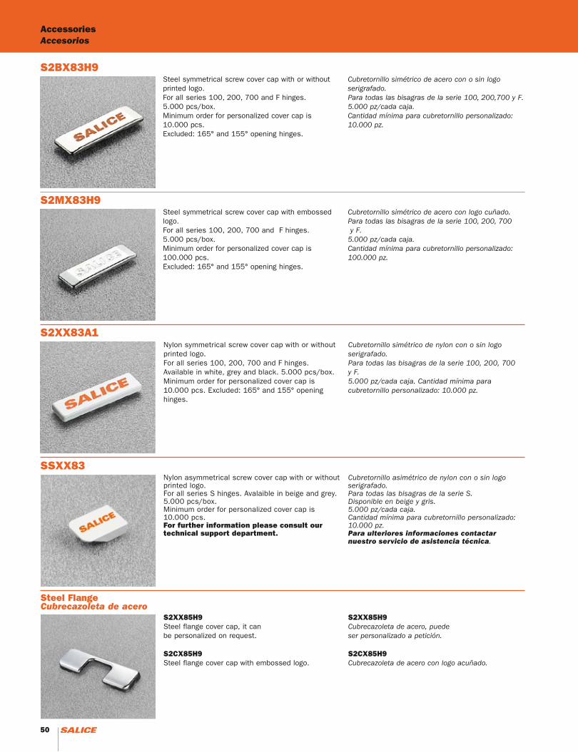
S2XX85H9Steel flange cover cap, it can be personalized on request.
S2CX85H9Steel flange cover cap with embossed logo.
S2XX85H9Cubrecazoleta de acero, puedeser personalizado a petición.
S2CX85H9Cubrecazoleta de acero con logo acuñado.
Nylon symmetrical screw cover cap with or without printed logo. For all series 100, 200, 700 and F hinges. Available in white, grey and black. 5.000 pcs/box. Minimum order for personalized cover cap is 10.000 pcs. Excluded: 165° and 155° opening hinges.
Cubretornillo simétrico de nylon con o sin logo serigrafado. Para todas las bisagras de la serie 100, 200, 700y F. 5.000 pz/cada caja. Cantidad mínima para cubretornillo personalizado: 10.000 pz.
S2XX83A1
Steel symmetrical screw cover cap with or without printed logo. For all series 100, 200, 700 and F hinges. 5.000 pcs/box.Minimum order for personalized cover cap is 10.000 pcs.Excluded: 165° and 155° opening hinges.
Cubretornillo simétrico de acero con o sin logo serigrafado. Para todas las bisagras de la serie 100, 200,700 y F. 5.000 pz/cada caja. Cantidad mínima para cubretornillo personalizado: 10.000 pz.
S2BX83H9
Steel symmetrical screw cover cap with embossed logo. For all series 100, 200, 700 and F hinges.5.000 pcs/box. Minimum order for personalized cover cap is 100.000 pcs.Excluded: 165° and 155° opening hinges.
Cubretornillo simétrico de acero con logo cuñado. Para todas las bisagras de la serie 100, 200, 700 y F. 5.000 pz/cada caja. Cantidad mínima para cubretornillo personalizado: 100.000 pz.
S2MX83H9
Steel FlangeCubrecazoleta de acero
Nylon asymmetrical screw cover cap with or without printed logo. For all series S hinges. Avalaible in beige and grey. 5.000 pcs/box.Minimum order for personalized cover cap is 10.000 pcs.For further information please consult our technical support department.
Cubretornillo asimétrico de nylon con o sin logo serigrafado. Para todas las bisagras de la serie S. Disponible en beige y gris. 5.000 pz/cada caja. Cantidad mínima para cubretornillo personalizado: 10.000 pz.Para ulteriores informaciones contactar nuestro servicio de asistencia técnica.
SSXX83
50 51
S2A637XF
S2AF37X3
S2BF37XY
SBA237XG
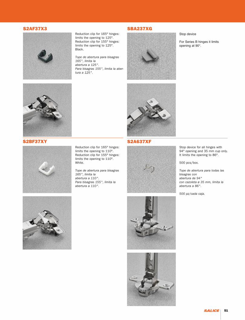
Stop device for all hinges with 94° opening and 35 mm cup only.It limits the opening to 86°. 500 pcs/box.
Tope de abertura para todas las bisagras con abertura de 94°con cazoleta ø 35 mm, limita la abertura a 86°. 500 pz/cada caja.
Reduction clip for 165° hinges: limits the opening to 125°.Reduction clip for 155° hinges: limits the opening to 125°.Black.
Tope de abertura para bisagras 165°, limita la abertura a 125°.Para bisagras 155°, limita la aber-tura a 125°.
Reduction clip for 165° hinges: limits the opening to 110°.Reduction clip for 155° hinges: limits the opening to 110°.White.
Tope de abertura para bisagras 165°, limita la abertura a 110°.Para bisagras 155°, limita la abertura a 110°.
Stop device
For Series B hinges it limits opening at 90°.
50 51

52
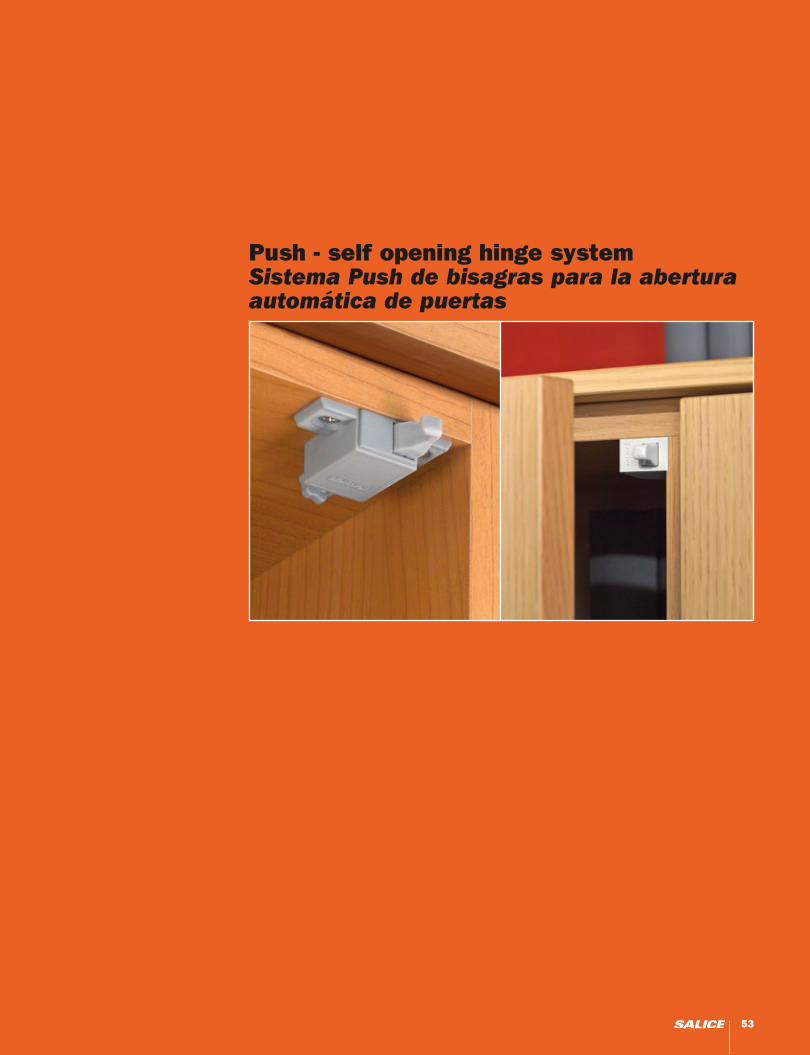
Push - self opening hinge system Sistema Push de bisagras para la abertura automática de puertas
53
Push
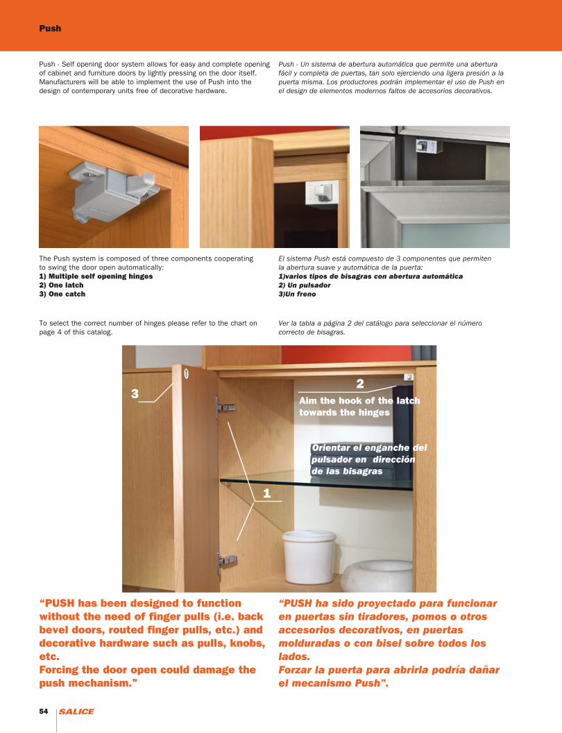
Push - Self opening door system allows for easy and complete opening of cabinet and furniture doors by lightly pressing on the door itself. Manufacturers will be able to implement the use of Push into the design of contemporary units free of decorative hardware.
Push - Un sistema de abertura automática que permite una abertura fácil y completa de puertas, tan solo ejerciendo una ligera presión a la puerta misma. Los productores podrán implementar el uso de Push en el design de elementos modernos faltos de accesorios decorativos.
The Push system is composed of three components cooperating to swing the door open automatically:1) Multiple self opening hinges2) One latch3) One catch
El sistema Push está compuesto de 3 componentes que permiten la abertura suave y automática de la puerta:1)varios tipos de bisagras con abertura automática2) Un pulsador3)Un freno
To select the correct number of hinges please refer to the chart on page 4 of this catalog.
Ver la tabla a página 2 del catálogo para seleccionar el número correcto de bisagras.
“PUSH has been designed to function without the need of finger pulls (i.e. back bevel doors, routed finger pulls, etc.) and decorative hardware such as pulls, knobs, etc. Forcing the door open could damage the push mechanism.”
“PUSH ha sido proyectado para funcionar en puertas sin tiradores, pomos o otros accesorios decorativos, en puertas molduradas o con bisel sobre todos los lados. Forzar la puerta para abrirla podría dañar el mecanismo Push”.
32
1
Aim the hook of the latch towards the hinges
Orientar el enganche del pulsador en dirección de las bisagras
54 55
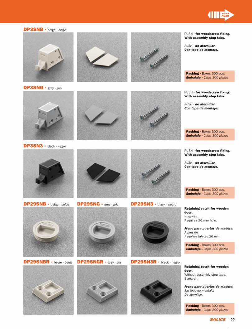
DP3SNB - beige - beige
DP3SNG - grey - gris
DP3SN3 - black - negro
PUSH - for woodscrew fixing.With assembly stop tabs.
PUSH - de atornillar.Con tope de montaje.
PUSH - for woodscrew fixing.With assembly stop tabs.
PUSH - de atornillar.Con tope de montaje.
PUSH - for woodscrew fixing.With assembly stop tabs.
PUSH - de atornillar.Con tope de montaje.
Packing - Boxes 300 pcs.Embalaje - Cajas 300 piezas
DP29SN3 - black - negroDP29SNG - grey - grisDP29SNB - beige - beige
DP29SN3R - black - negroDP29SNGR - grey - grisDP29SNBR - beige - beige
Retaining catch for wooden door.Knock-in.Requires 26 mm hole.
Freno para puertas de madera.A presión.Requiere taladro 26 mm
Retaining catch for wooden door.Without assembly stop tabs.Screw-on.
Freno para puertas de madera.Sin tope de montaje. De atornillar.
Packing - Boxes 300 pcs.Embalaje - Cajas 300 piezas
Packing - Boxes 300 pcs.Embalaje - Cajas 300 piezas
Packing - Boxes 300 pcs.Embalaje - Cajas 300 piezas
Packing - Boxes 300 pcs.Embalaje - Cajas 300 piezas
54 55
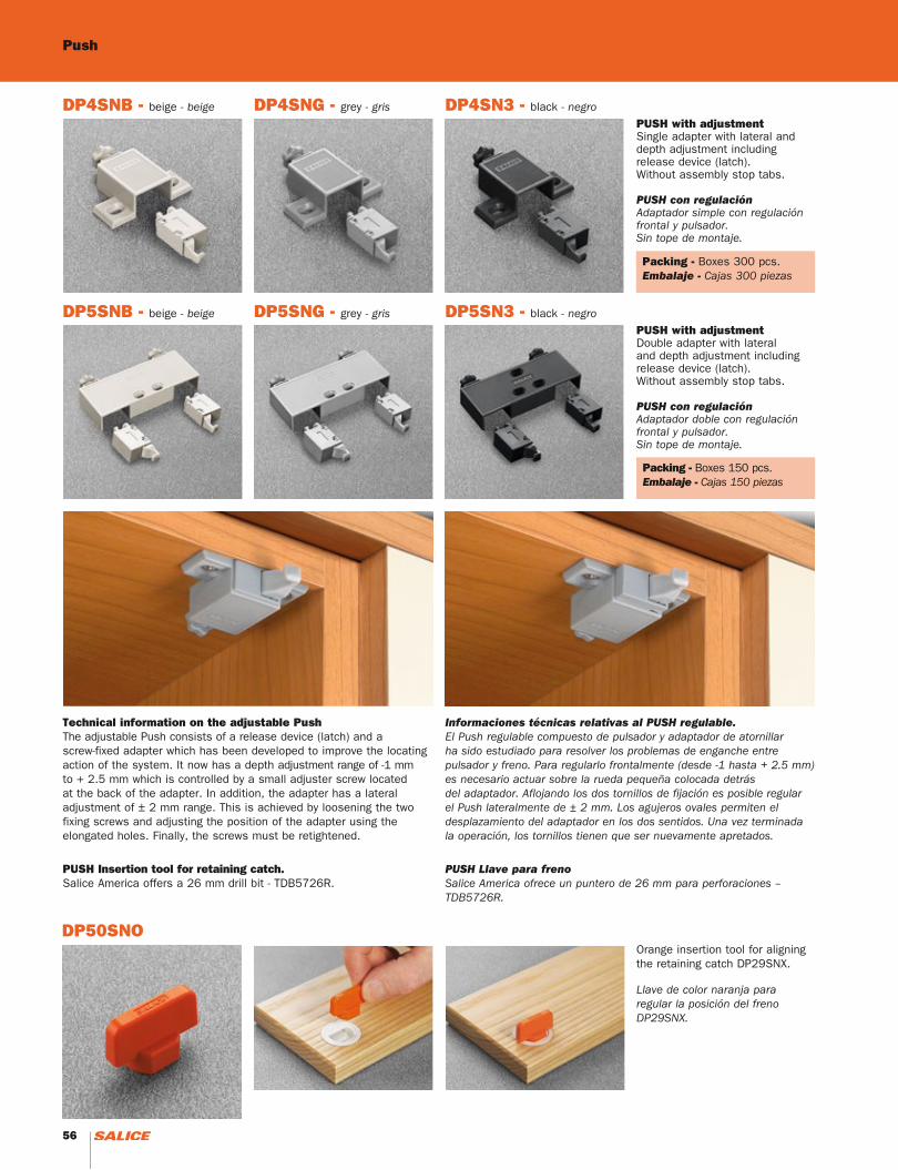
DP4SN3 - black - negroDP4SNG - grey - grisDP4SNB - beige - beige
DP5SN3 - black - negroDP5SNG - grey - grisDP5SNB - beige - beige
PUSH with adjustmentSingle adapter with lateral and depth adjustment including release device (latch).Without assembly stop tabs.
PUSH con regulación Adaptador simple con regulaciónfrontal y pulsador. Sin tope de montaje.
PUSH with adjustmentDouble adapter with lateral and depth adjustment including release device (latch).Without assembly stop tabs.
PUSH con regulación Adaptador doble con regulaciónfrontal y pulsador. Sin tope de montaje.
Technical information on the adjustable PushThe adjustable Push consists of a release device (latch) and a screw-fixed adapter which has been developed to improve the locating action of the system. It now has a depth adjustment range of -1 mm to + 2.5 mm which is controlled by a small adjuster screw located at the back of the adapter. In addition, the adapter has a lateral adjustment of ± 2 mm range. This is achieved by loosening the two fixing screws and adjusting the position of the adapter using the elongated holes. Finally, the screws must be retightened.
Informaciones técnicas relativas al PUSH regulable.El Push regulable compuesto de pulsador y adaptador de atornillar ha sido estudiado para resolver los problemas de enganche entre pulsador y freno. Para regularlo frontalmente (desde -1 hasta + 2.5 mm) es necesario actuar sobre la rueda pequeña colocada detrás del adaptador. Aflojando los dos tornillos de fijación es posible regular el Push lateralmente de ± 2 mm. Los agujeros ovales permiten el desplazamiento del adaptador en los dos sentidos. Una vez terminada la operación, los tornillos tienen que ser nuevamente apretados.
PUSH Insertion tool for retaining catch.Salice America offers a 26 mm drill bit - TDB5726R.
PUSH Llave para frenoSalice America ofrece un puntero de 26 mm para perforaciones – TDB5726R.
DP50SNOOrange insertion tool for aligning the retaining catch DP29SNX.
Llave de color naranja para regular la posición del freno DP29SNX.
Packing - Boxes 300 pcs.Embalaje - Cajas 300 piezas
Packing - Boxes 150 pcs.Embalaje - Cajas 150 piezas
Push
56 57
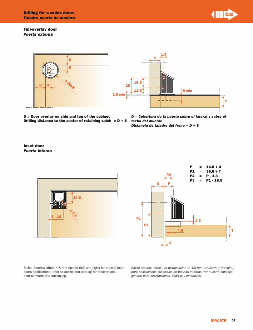
Drilling for wooden doorsTaladro puerta de madera
P = 14.8 + AP1 = 36.8 + TP2 = P - 1.3P3 = P1 - 16.5
D = Door overlay on side and top of the cabinet Drilling distance to the center of retaining catch = D + 8
D = Cobertura de la puerta sobre el lateral y sobre el techo del muebleDistancia de taladro del freno = D + 8
Full-overlay doorPuerta externa
Inset doorPuerta interna
Salice America offers 4.8 mm spacer (left and right) for special inset doors applications; refer to our master catalog for descriptions,item numbers and packaging.
Salice America ofrece un distanciador de 4,8 mm (izquierdo y derecho), para aplicaciones especiales de puertas internas; ver nuestro catálogo general para descripciones, códigos y embalajes.
56 57
Push - With adjustmentPush - Con regulación
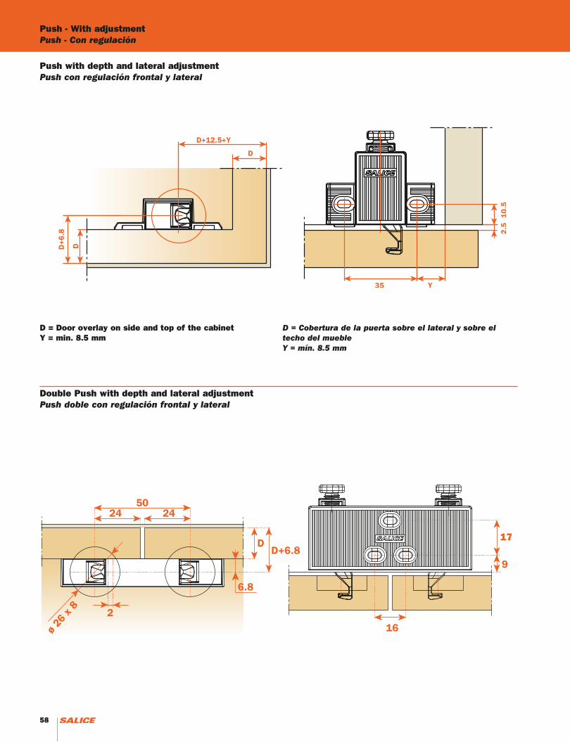
D = Door overlay on side and top of the cabinet Y = min. 8.5 mm
D = Cobertura de la puerta sobre el lateral y sobre el techo del muebleY = mín. 8.5 mm
Push with depth and lateral adjustmentPush con regulación frontal y lateral
Double Push with depth and lateral adjustmentPush doble con regulación frontal y lateral
58 59
Magnetic release devicePulsador magnético
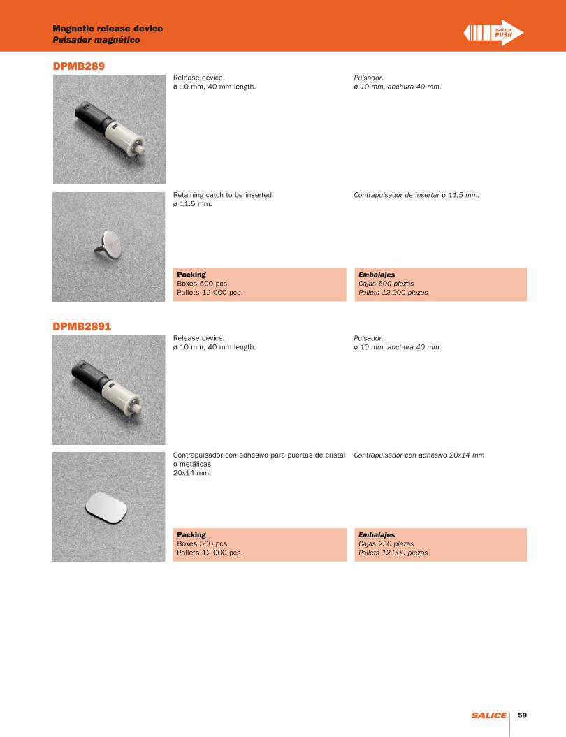
DPMB289
DPMB2891
EmbalajesCajas 250 piezasPallets 12.000 piezas
EmbalajesCajas 500 piezasPallets 12.000 piezas
PackingBoxes 500 pcs.Pallets 12.000 pcs.
PackingBoxes 500 pcs.Pallets 12.000 pcs.
Retaining catch to be inserted. ø 11.5 mm.
Contrapulsador de insertar ø 11,5 mm.
Contrapulsador con adhesivo para puertas de cristal o metálicas20x14 mm.
Contrapulsador con adhesivo 20x14 mm
Release device.ø 10 mm, 40 mm length.
Pulsador.ø 10 mm, anchura 40 mm.
Release device.ø 10 mm, 40 mm length.
Pulsador.ø 10 mm, anchura 40 mm.
58 59

Push - AdaptersPush - Adaptadores
DP84SNBR
DP82XXBR
DP83XXBR
Adjustable plastic adapter for release device. To be fixed with woodscrews.8x32 mm drilling.DP84xxBR = beige DP84xxQR = brown* DP84xxGR = grey* DP84xx3R = black
Adaptador regulable de plástico para pulsador. Fijación por tornillos para madera. Taladro 8x32 mm. DP84xxBR = beige DP84xxQR = marrón* DP84xxGR = gris* DP84xx3R = negro
Adjustable longitudinal plastic adapter for release device. To be fixed with woodscrews. 8+16 mm drilling. Screw cover to be ordered separately.DP82xxBR = beige DP82xxQR = brown* DP82xxGR = grey* DP82xx3R = black* The cover cap shown in the picture has to be ordered separately.
Adaptador longitudinal regulable de plástico para pulsador. Fijación por tornillos para madera. Taladro 8+16 mm. Cubretornillo a pedir separadamente.DP83xxBR = beige DP83xxQR = marrón* DP83xxGR = gris* DP83xx3R = negro* Solo pedido especial.
PackingBoxes 500 pcs.Pallets 12.000 pcs.
Adjustable double plastic adapter for release device. To be fixed with woodscrews.8+32 mm drilling.Screw cover to be ordered separately.DP83xxBR = beige DP83xxQR = brown* DP83xxGR = grey* DP83xx3R = black* The cover cap shown in the picture has to be ordered separately.
Adaptador doble regulable de plástico para pulsador. Fijación por tornillos para madera. Taladro 8+32 mm. Cubretornillo a pedir separadamente.DP83xxBR = beige DP83xxQR = marrón* DP83xxGR = gris* DP83xx3R = negro* Solo pedido especial.
EmbalajesCajas 500 piezasPaletas 12.000 piezas
PackingBoxes 500 pcs.Pallets 12.000 pcs.
EmbalajesCajas 500 piezasPaletas 12.000 piezas
PackingBoxes 500 pcs.Pallets 12.000 pcs.
EmbalajesCajas 500 piezasPaletas 12.000 piezas
60 61
Release device applicationInformaciones técnicas - Aplicación del pulsador.
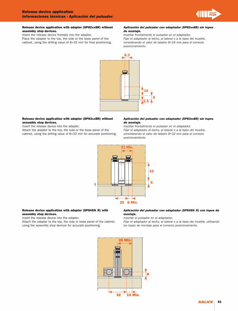
Release device application with adapter (DP82xxBR) without assembly stop devices.Insert the release device frontally into the adapter.Place the adapter to the top, the side or the base panel of thecabinet, using the drilling value of 8+16 mm for final positioning.
Aplicación del pulsador con adaptador (DP82xxBR) sin topes de montaje.Insertar frontalmente el pulsador en el adaptador.Fijar el adaptador al techo, al lateral o a la base del mueble, considerando el valor de taladro 8+16 mm para el correcto posicionamiento.
Release device application with adapter (DP83xxBR) without assembly stop devices.Insert the release device into the adapter.Attach the adapter to the top, the side or the base panel of thecabinet, using the drilling value of 8+32 mm for accurate positioning.
Aplicación del pulsador con adaptador (DP83xxBR) sin topes de montaje.Insertar frontalmente el pulsador en el adaptador.Fijar el adaptador al techo, al lateral o a la base del mueble, considerando el valor de taladro 8+32 mm para el correcto posicionamiento.
Release device application with adapter (DP84SN_R) with assembly stop devices.Insert the release device into the adapter.Attach the adapter to the top, the side or base panel of the cabinet, using the assembly stop devices for accurate positioning.
Aplicación del pulsador con adaptador (DP84SN_R) con topes de montaje.Insertar el pulsador en el adaptador.Fijar el adaptador al techo, al lateral o a la base del mueble, utilizando los topes de montaje para el correcto posicionamiento.
60 61
Push - Release device applicationPush - Informaciones técnicas - Aplicación del pulsador.
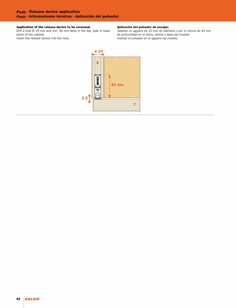
Application of the release device to be recessed.Drill a hole Ø 10 mm and min. 40 mm deep in the top, side or base panel of the cabinet.Insert the release device into the hole.
Aplicación del pulsador de encajar.Taladrar un agujero de 10 mm de diámetro y por lo menos de 40 mm de profundidad en el techo, lateral o base del mueble.Insertar el pulsador en el agujero del mueble.
62 63
Release device applicationInformaciones técnicas - Aplicación del pulsador.
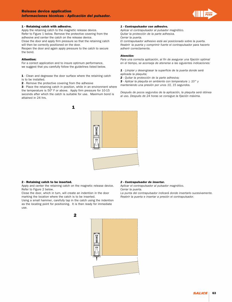
1 - Retaining catch with adhesive.Apply the retaining catch to the magnetic release device. Refer to Figure 1 below. Remove the protective covering from the adhesive and center the catch on the release device. Close the door and apply firm pressure so that the retaining catch will then be correctly positioned on the door. Reopen the door and again apply pressure to the catch to secure the bond. Attention:For a correct application and to insure optimum performance, we suggest that you carefully follow the guidelines listed below.
1 - Clean and degrease the door surface where the retaining catch is to be installed.2 - Remove the protective covering from the adhesive3 - Place the retaining catch in position, while in an environment where the temperature is 50° F or above. Apply firm pressure for 10-15 seconds after which the catch is suitable for use. Maximum bond is attained in 24 hrs.
1 - Contrapulsador con adhesivo.Aplicar el contrapulsador al pulsador magnético.Quitar la protección de la parte adhesiva. Cerrar la puerta.El contrapulsador adhesivo está así posicionado sobre la puerta.Reabrir la puerta y comprimir fuerte el contrapulsador para hacerloadherir correctamente.
Atención:Para una correcta aplicación, al fin de asegurar una fijación optimal en el tiempo, se aconseja de atenerse a las siguientes indicaciones:
1 - Limpiar y desengrasar la superficie de la puerta donde será aplicada la plaquita;2 - Quitar la protección de la parte adhesiva;3 - Aplicar la plaquita en ambiente con temperatura ≥ 10° y manteniendo una presión por unos 10, 15 segundos.
Después de pocos segundos de la aplicación, la plaquita será idónea al uso. Después de 24 horas se consigue la fijación máxima.
2 - Retaining catch to be inserted.Apply and center the retaining catch on the magnetic release device. Refer to Figure 2 below. Close the door, which in turn, will create an indention in the door marking the location where the catch is to be inserted. Using a small hammer, carefully tap in the catch using the indention as the locating point for positioning. It is then ready for immediate use.
2 - Contrapulsador de insertar.Aplicar el contrapulsador al pulsador magnético.Cerrar la puerta. La punta del contrapulsador indicará donde insertarlo sucesivamente.Reabrir la puerta e insertar a presión el contrapulsador.
1
2
62 63
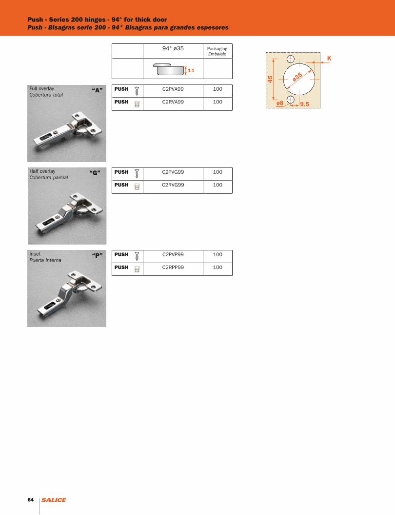
Push - Series 200 hinges - 94° for thick doorPush - Bisagras serie 200 - 94° Bisagras para grandes espesores
Full overlayCobertura total
Half overlayCobertura parcial
InsetPuerta interna
“A”
“G”
“P”
94° ø35
PUSH C2PVA99 100
PUSH C2RVA99 100
PUSH C2PVG99 100
PUSH C2RVG99 100
PUSH C2PVP99 100
PUSH C2RPP99 100
PackagingEmbalaje
64
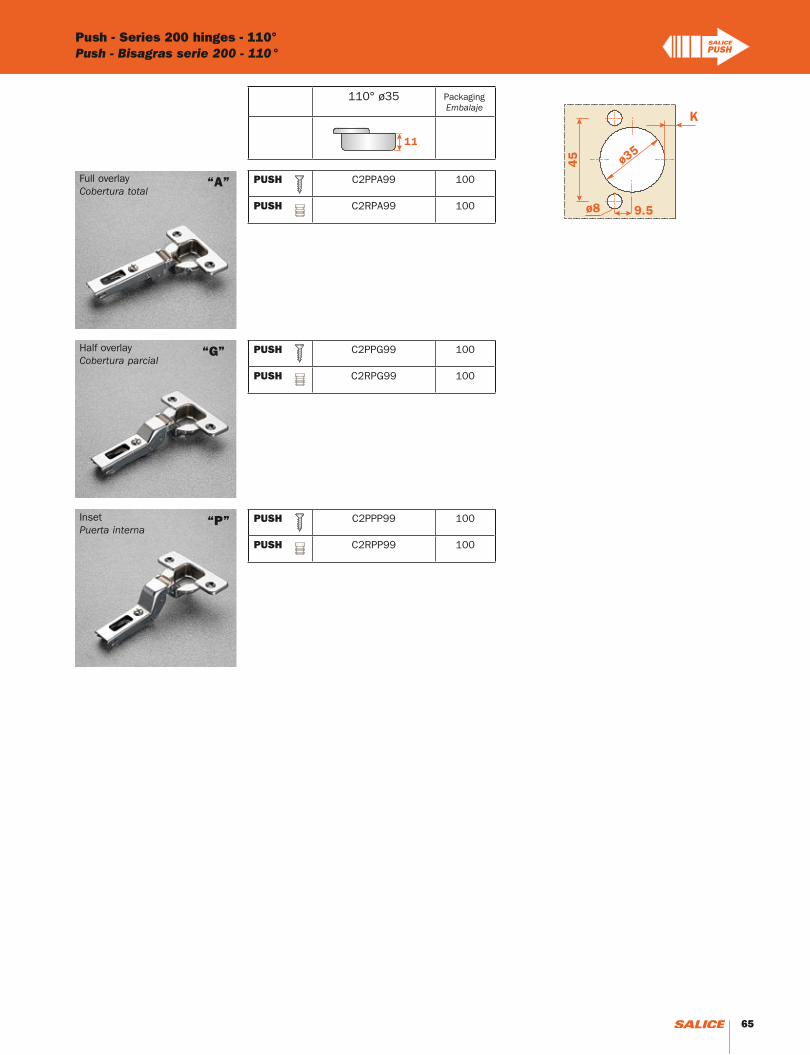
Push - Series 200 hinges - 110°Push - Bisagras serie 200 - 110°
Full overlayCobertura total
Half overlayCobertura parcial
InsetPuerta interna
“A”
“G”
“P”
110° ø35
PUSH C2PPA99 100
PUSH C2RPA99 100
PUSH C2PPG99 100
PUSH C2RPG99 100
PUSH C2PPP99 100
PUSH C2RPP99 100
PackagingEmbalaje
65
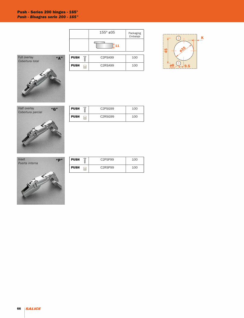
Push - Series 200 hinges - 165°Push - Bisagras serie 200 - 165°
Full overlayCobertura total
Half overlayCobertura parcial
InsetPuerta interna
“A”
“G”
“P”
155° ø35
PUSH C2PSA99 100
PUSH C2RSA99 100
PUSH C2PSG99 100
PUSH C2RSG99 100
PUSH C2PSP99 100
PUSH C2RSP99 100
PackagingEmbalaje
66 67
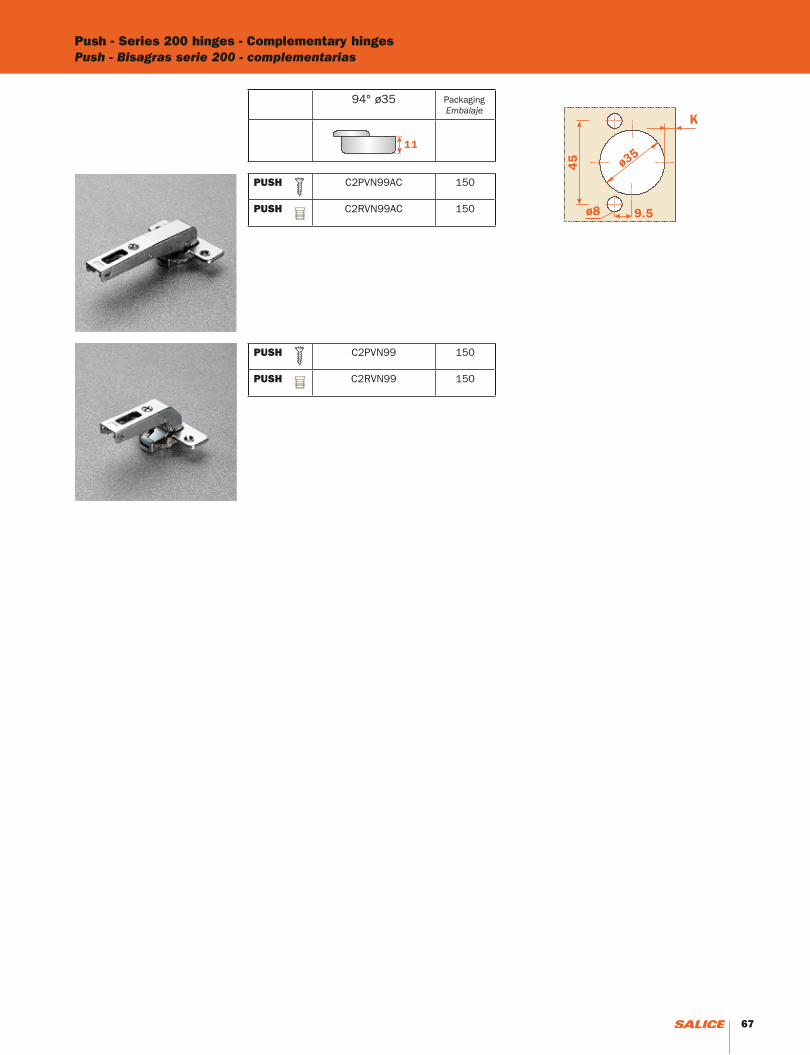
Push - Series 200 hinges - Complementary hingesPush - Bisagras serie 200 - complementarias
94° ø35
PUSH C2PVN99AC 150
PUSH C2RVN99AC 150
PUSH C2PVN99 150
PUSH C2RVN99 150
PackagingEmbalaje
66 67

68
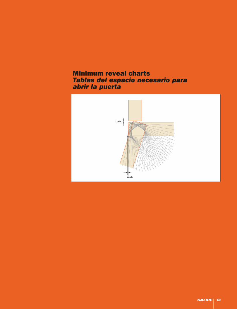
Minimum reveal chartsTablas del espacio necesario para abrir la puerta
69
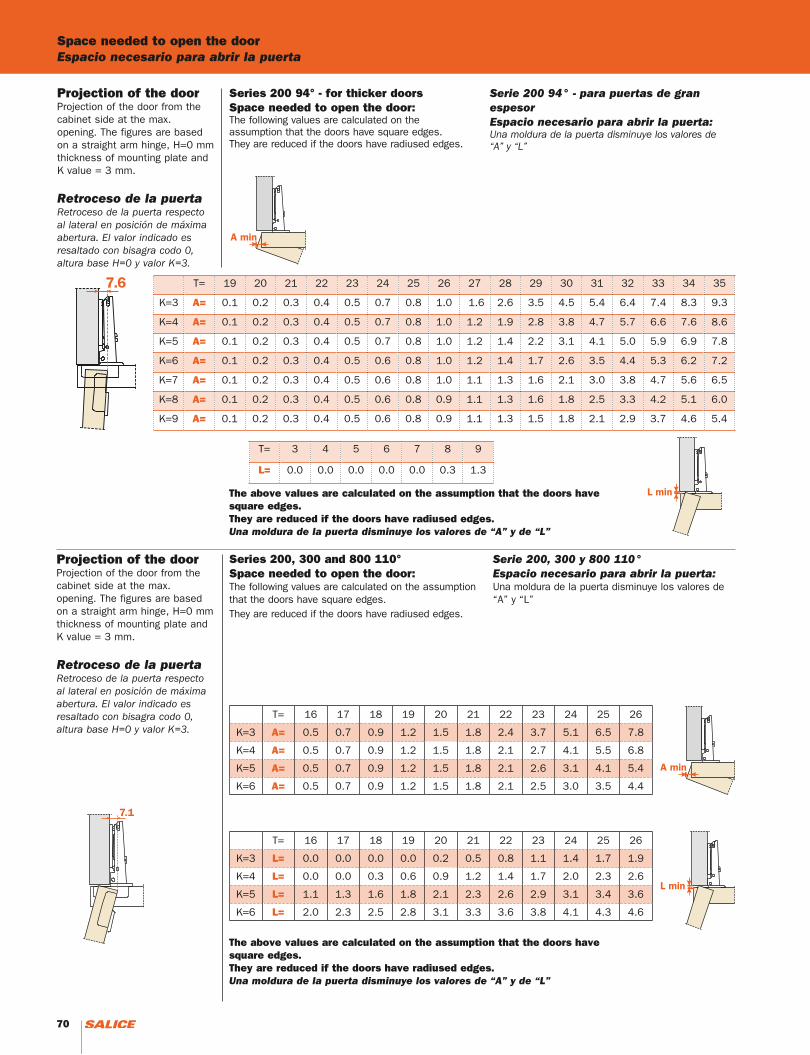
Series 200 94° - for thicker doorsSpace needed to open the door:The following values are calculated on the assumption that the doors have square edges.They are reduced if the doors have radiused edges.
Serie 200 94° - para puertas de gran espesorEspacio necesario para abrir la puerta:Una moldura de la puerta disminuye los valores de “A” y “L”
Projection of the doorProjection of the door from the cabinet side at the max. opening. The figures are based on a straight arm hinge, H=0 mm thickness of mounting plate and K value = 3 mm.
Retroceso de la puertaRetroceso de la puerta respecto al lateral en posición de máxima abertura. El valor indicado es resaltado con bisagra codo 0, altura base H=0 y valor K=3.
T= 19 20 21 22 23 24 25 26 27 28 29 30 31 32 33 34 35
K=3 A= 0.1 0.2 0.3 0.4 0.5 0.7 0.8 1.0 1.6 2.6 3.5 4.5 5.4 6.4 7.4 8.3 9.3
K=4 A= 0.1 0.2 0.3 0.4 0.5 0.7 0.8 1.0 1.2 1.9 2.8 3.8 4.7 5.7 6.6 7.6 8.6
K=5 A= 0.1 0.2 0.3 0.4 0.5 0.7 0.8 1.0 1.2 1.4 2.2 3.1 4.1 5.0 5.9 6.9 7.8
K=6 A= 0.1 0.2 0.3 0.4 0.5 0.6 0.8 1.0 1.2 1.4 1.7 2.6 3.5 4.4 5.3 6.2 7.2
K=7 A= 0.1 0.2 0.3 0.4 0.5 0.6 0.8 1.0 1.1 1.3 1.6 2.1 3.0 3.8 4.7 5.6 6.5
K=8 A= 0.1 0.2 0.3 0.4 0.5 0.6 0.8 0.9 1.1 1.3 1.6 1.8 2.5 3.3 4.2 5.1 6.0
K=9 A= 0.1 0.2 0.3 0.4 0.5 0.6 0.8 0.9 1.1 1.3 1.5 1.8 2.1 2.9 3.7 4.6 5.4
T= 3 4 5 6 7 8 9
L= 0.0 0.0 0.0 0.0 0.0 0.3 1.3
Projection of the doorProjection of the door from the cabinet side at the max. opening. The figures are based on a straight arm hinge, H=0 mm thickness of mounting plate and K value = 3 mm.
Retroceso de la puertaRetroceso de la puerta respecto al lateral en posición de máxima abertura. El valor indicado es resaltado con bisagra codo 0, altura base H=0 y valor K=3.
Series 200, 300 and 800 110°Space needed to open the door:The following values are calculated on the assumption that the doors have square edges.They are reduced if the doors have radiused edges.
Serie 200, 300 y 800 110°Espacio necesario para abrir la puerta:Una moldura de la puerta disminuye los valores de “A” y “L”
T= 16 17 18 19 20 21 22 23 24 25 26
K=3 A= 0.5 0.7 0.9 1.2 1.5 1.8 2.4 3.7 5.1 6.5 7.8
K=4 A= 0.5 0.7 0.9 1.2 1.5 1.8 2.1 2.7 4.1 5.5 6.8
K=5 A= 0.5 0.7 0.9 1.2 1.5 1.8 2.1 2.6 3.1 4.1 5.4
K=6 A= 0.5 0.7 0.9 1.2 1.5 1.8 2.1 2.5 3.0 3.5 4.4
T= 16 17 18 19 20 21 22 23 24 25 26
K=3 L= 0.0 0.0 0.0 0.0 0.2 0.5 0.8 1.1 1.4 1.7 1.9
K=4 L= 0.0 0.0 0.3 0.6 0.9 1.2 1.4 1.7 2.0 2.3 2.6
K=5 L= 1.1 1.3 1.6 1.8 2.1 2.3 2.6 2.9 3.1 3.4 3.6
K=6 L= 2.0 2.3 2.5 2.8 3.1 3.3 3.6 3.8 4.1 4.3 4.6
Space needed to open the doorEspacio necesario para abrir la puerta
The above values are calculated on the assumption that the doors have square edges.They are reduced if the doors have radiused edges.Una moldura de la puerta disminuye los valores de “A” y de “L”
The above values are calculated on the assumption that the doors have square edges.They are reduced if the doors have radiused edges.Una moldura de la puerta disminuye los valores de “A” y de “L”
70 71
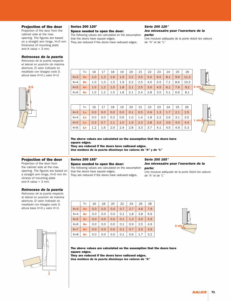
Series 200 120°Space needed to open the door:The following values are calculated on the assumption that the doors have square edges.They are reduced if the doors have radiused edges.
Série 200 120°Jeu nécessaire pour l’ouverture de la porte:Une moulure adéquate de la porte réduit les valeursde “A” et de “L”
Projection of the doorProjection of the door from the cabinet side at the max. opening. The figures are based on a straight arm hinge, H=0 mm thickness of mounting plate and K value = 3 mm.
Retroceso de la puertaRetroceso de la puerta respecto al lateral en posición de máxima abertura. El valor indicado es resaltado con bisagra codo 0, altura base H=0 y valor K=3.
T= 16 17 18 19 20 21 22 23 24 25 26
K=3 A= 1.0 1.3 1.6 1.9 2.2 3.5 5.0 6.5 8.1 9.6 11.2
K=4 A= 1.0 1.3 1.5 1.9 2.2 2.5 4.0 5.5 7.1 8.6 10.2
K=5 A= 1.0 1.2 1.5 1.8 2.1 2.5 3.0 4.5 6.1 7.6 9.2
K=6 A= 1.0 1.2 1.5 1.8 2.1 2.4 2.8 3.5 5.1 6.6 8.1
T= 16 17 18 19 20 21 22 23 24 25 26
K=3 L= 0.0 0.0 0.0 0.0 0.1 0.5 0.9 1.3 1.7 2.1 2.5
K=4 L= 0.0 0.0 0.2 0.6 1.0 1.4 1.8 2.2 2.6 3.1 3.5
K=5 L= 0.3 0.7 1.1 1.5 1.9 2.3 2.8 3.2 3.6 4.0 4.4
K=6 L= 1.2 1.6 2.0 2.4 2.8 3.3 3.7 4.1 4.5 4.9 5.3
Projection of the doorProjection of the door from the cabinet side at the max. opening. The figures are based on a straight arm hinge, H=0 mm thi-ckness of mounting plate and K value = 3 mm.
Retroceso de la puertaRetroceso de la puerta respecto al lateral en posición de máxima abertura. El valor indicado es resaltado con bisagra codo 0, altura base H=0 y valor K=3.
Series 200 165°Space needed to open the door:The following values are calculated on the assumption that the doors have square edges.They are reduced if the doors have radiused edges.
Série 200 165°Jeu nécessaire pour l’ouverture de la porte:Une moulure adéquate de la porte réduit les valeurs de “A” et de “L”
T= 16 18 20 22 24 26 28
K=3 A= 0.0 0.0 0.0 0.7 2.7 4.6 7.9
K=4 A= 0.0 0.0 0.0 0.1 1.8 3.8 6.9
K=5 A= 0.0 0.0 0.0 0.1 1.2 3.0 5.9
K=6 A= 0.0 0.0 0.0 0.1 0.9 2.5 4.9
K=7 A= 0.0 0.0 0.0 0.1 0.7 2.0 3.9
K=8 A= 0.0 0.0 0.0 0.1 0.6 1.7 3.2
The above values are calculated on the assumption that the doors have square edges.They are reduced if the doors have radiused edges.Una moldura de la puerta disminuye los valores de “A” y de “L”
The above values are calculated on the assumption that the doors have square edges.They are reduced if the doors have radiused edges.Una moldura de la puerta disminuye los valores de “A”
70 71
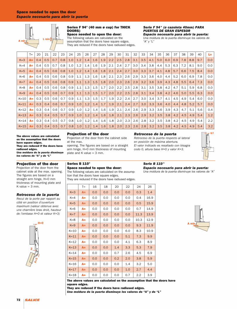
Series F 94° (40 mm ø cup) for THICK DOORS)Space needed to open the door:The following values are calculated on the assumption that the doors have square edges.They are reduced if the doors have radiused edges.
Serie F 94° (ø cazoleta 40mm) PARA PUERTAS DE GRAN ESPESOREspacio necesario para abrir la puerta:Una moldura de la puerta disminuye los valores de “A” y “L”
Projection of the doorProjection of the door from the cabinet side at the max. opening. The figures are based on a straight arm hinge, H=0 mm thickness of mounting plate and K value = 3 mm.
Retroceso de la puertaRetroceso de la puerta respecto al lateral en posición de máxima abertura. El valor indicado es resaltado con bisagra codo 0, altura base H=0 y valor K=3.
T= 20 21 22 23 24 25 26 27 28 29 30 31 32 33 34 35 36 37 38 39 40 L=
K=3 A= 0.4 0.5 0.7 0.8 1.0 1.2 1.4 1.6 1.9 2.2 2.5 2.8 3.1 3.5 4.1 5.0 6.0 6.9 7.8 8.8 9.7 0.0
K=4 A= 0.4 0.5 0.7 0.8 1.0 1.2 1.4 1.6 1.9 2.1 2.4 2.7 3.0 3.4 3.8 4.4 5.3 6.3 7.2 8.1 9.0 0.0
K=5 A= 0.4 0.5 0.6 0.8 1.0 1.2 1.4 1.6 1.8 2.1 2.4 2.7 3.0 3.3 3.7 4.1 4.8 5.7 6.6 7.5 8.4 0.0
K=6 A= 0.4 0.5 0.6 0.8 0.9 1.1 1.3 1.6 1.8 2.1 2.3 2.6 2.9 3.3 3.6 4.0 4.4 5.2 6.0 6.9 7.8 0.0
K=7 A= 0.4 0.5 0.6 0.8 0.9 1.1 1.3 1.5 1.8 2.0 2.3 2.6 2.9 3.2 3.6 3.9 4.3 4.8 5.5 6.4 7.3 0.0
K=8 A= 0.4 0.5 0.6 0.8 0.9 1.1 1.3 1.5 1.7 2.0 2.2 2.5 2.8 3.1 3.5 3.8 4.2 4.7 5.1 5.9 6.8 0.0
K=9 A= 0.4 0.5 0.6 0.7 0.9 1.1 1.3 1.5 1.7 2.0 2.2 2.5 2.8 3.1 3.4 3.8 4.2 4.6 5.0 5.5 6.3 0.0
K=10 A= 0.3 0.5 0.6 0.7 0.9 1.1 1.3 1.5 1.7 1.9 2.2 2.4 2.7 3.0 3.4 3.7 4.1 4.5 4.9 5.4 6.0 0.0
K=11 A= 0.3 0.4 0.6 0.7 0.9 1.0 1.2 1.4 1.7 1.9 2.1 2.4 2.7 3.0 3.3 3.6 4.0 4.4 4.8 5.2 5.7 0.0
K=12 A= 0.3 0.4 0.6 0.7 0.9 1.0 1.2 1.4 1.6 1.9 2.1 2.4 2.6 2.9 3.3 3.6 3.9 4.3 4.7 5.1 5.6 0.4
K=13 A= 0.3 0.4 0.5 0.7 0.9 1.0 1.2 1.4 1.6 1.8 2.1 2.3 2.6 2.9 3.2 3.5 3.8 4.2 4.5 4.9 5.4 1.2
K=14 A= 0.3 0.4 0.5 0.7 0.8 1.0 1.2 1.4 1.6 1.8 2.0 2.3 2.6 2.8 3.2 3.5 3.8 4.2 4.5 4.9 5.4 2.2
K=15 A= 0.3 0.4 0.5 0.7 0.8 1.0 1.2 1.4 1.6 1.8 2.0 2.3 2.6 2.8 3.2 3.5 3.8 4.2 4.5 4.9 5.4 3.2
T= 16 18 20 22 24 26
K=3 A= 0.0 0.0 0.0 0.0 0.3 1.4
K=4 A= 0.0 0.0 0.0 0.0 0.4 16.9
K=5 A= 0.0 0.0 0.0 0.0 0.5 15.9
K=6 A= 0.0 0.0 0.0 0.0 0.7 14.9
K=7 A= 0.0 0.0 0.0 0.0 11.3 13.9
K=8 A= 0.0 0.0 0.0 0.0 10.3 12.9
K=9 A= 0.0 0.0 0.0 0.0 9.3 11.9
K=10 A= 0.0 0.0 0.0 6.0 8.3 10.9
K=11 A= 0.0 0.0 0.0 5.1 7.3 9.9
K=12 A= 0.0 0.0 0.0 4.1 6.3 8.9
K=13 A= 0.0 0.0 1.4 3.3 5.3 7.9
K=14 A= 0.0 0.0 0.7 2.6 4.5 6.9
K=15 A= 0.0 0.0 0.2 2.0 3.8 5.9
K=16 A= 0.0 0.0 0.0 1.4 3.2 5.0
K=17 A= 0.0 0.0 0.0 1.0 2.7 4.4
K=18 A= 0.0 0.0 0.0 0.7 2.2 3.9
Projection of the doorProjection of the door from the cabinet side at the max. opening. The figures are based on a straight arm hinge, H=0 mm thickness of mounting plate and K value = 3 mm.
Retroceso de la puertaRecul de la porte par rapport au côté en position d’ouverture maximum (valeur obtenue avec une charnière bras droit, hauteur de l’embase H=0 et valeur K=3)
Series B 110°Space needed to open the door:The following values are calculated on the assump-tion that the doors have square edges.They are reduced if the doors have radiused edges.
Serie B 110°Espacio necesario para abrir la puerta:Una moldura de la puerta disminuye los valores de “A”
Space needed to open the doorEspacio necesario para abrir la puerta
The above values are calculated on the assumption that the doors have square edges. They are reduced if the doors have radiused edges.Una moldura de la puerta disminuye los valores de “A” y de “L”
The above values are calculated on the assumption that the doors have square edges.They are reduced if the doors have radiused edges.Una moldura de la puerta disminuye los valores de “A” y de “L”
72 73
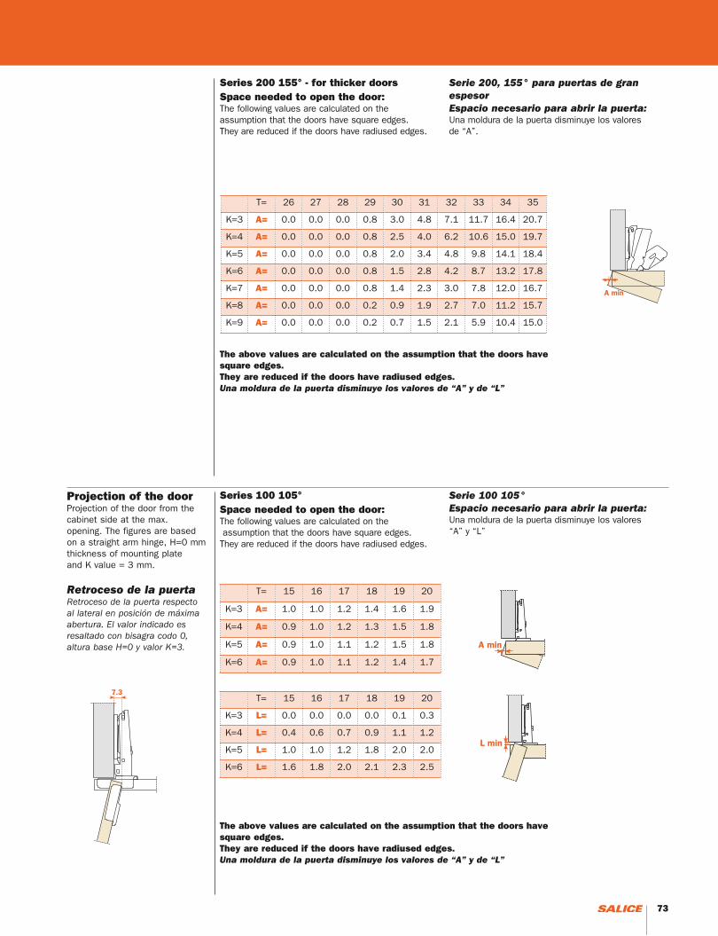
Series 200 155° - for thicker doorsSpace needed to open the door:The following values are calculated on the assumption that the doors have square edges.They are reduced if the doors have radiused edges.
Serie 200, 155° para puertas de gran espesorEspacio necesario para abrir la puerta:Una moldura de la puerta disminuye los valores de “A”.
Series 100 105°Space needed to open the door:The following values are calculated on the assumption that the doors have square edges.They are reduced if the doors have radiused edges.
Serie 100 105°Espacio necesario para abrir la puerta:Una moldura de la puerta disminuye los valores “A” y “L”
Projection of the doorProjection of the door from the cabinet side at the max. opening. The figures are based on a straight arm hinge, H=0 mm thickness of mounting plate and K value = 3 mm.
Retroceso de la puertaRetroceso de la puerta respecto al lateral en posición de máxima abertura. El valor indicado es resaltado con bisagra codo 0, altura base H=0 y valor K=3.
T= 26 27 28 29 30 31 32 33 34 35
K=3 A= 0.0 0.0 0.0 0.8 3.0 4.8 7.1 11.7 16.4 20.7
K=4 A= 0.0 0.0 0.0 0.8 2.5 4.0 6.2 10.6 15.0 19.7
K=5 A= 0.0 0.0 0.0 0.8 2.0 3.4 4.8 9.8 14.1 18.4
K=6 A= 0.0 0.0 0.0 0.8 1.5 2.8 4.2 8.7 13.2 17.8
K=7 A= 0.0 0.0 0.0 0.8 1.4 2.3 3.0 7.8 12.0 16.7
K=8 A= 0.0 0.0 0.0 0.2 0.9 1.9 2.7 7.0 11.2 15.7
K=9 A= 0.0 0.0 0.0 0.2 0.7 1.5 2.1 5.9 10.4 15.0
The above values are calculated on the assumption that the doors have square edges.They are reduced if the doors have radiused edges.Una moldura de la puerta disminuye los valores de “A” y de “L”
The above values are calculated on the assumption that the doors have square edges.They are reduced if the doors have radiused edges.Una moldura de la puerta disminuye los valores de “A” y de “L”
T= 15 16 17 18 19 20
K=3 A= 1.0 1.0 1.2 1.4 1.6 1.9
K=4 A= 0.9 1.0 1.2 1.3 1.5 1.8
K=5 A= 0.9 1.0 1.1 1.2 1.5 1.8
K=6 A= 0.9 1.0 1.1 1.2 1.4 1.7
T= 15 16 17 18 19 20
K=3 L= 0.0 0.0 0.0 0.0 0.1 0.3
K=4 L= 0.4 0.6 0.7 0.9 1.1 1.2
K=5 L= 1.0 1.0 1.2 1.8 2.0 2.0
K=6 L= 1.6 1.8 2.0 2.1 2.3 2.5
72 73
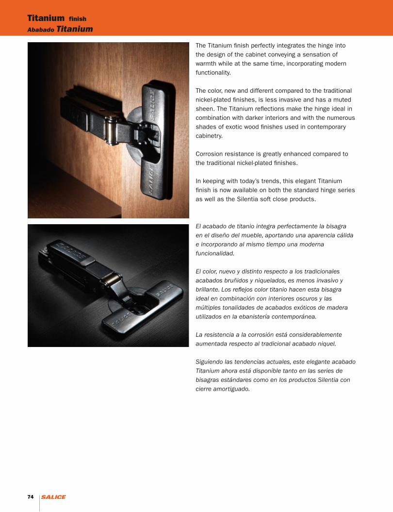
Titanium finish
Ababado Titanium
The Titanium finish perfectly integrates the hinge into the design of the cabinet conveying a sensation of warmth while at the same time, incorporating modern functionality.
The color, new and different compared to the traditional nickel-plated finishes, is less invasive and has a muted sheen. The Titanium reflections make the hinge ideal in combination with darker interiors and with the numerous shades of exotic wood finishes used in contemporary cabinetry.
Corrosion resistance is greatly enhanced compared to the traditional nickel-plated finishes.
In keeping with today’s trends, this elegant Titanium finish is now available on both the standard hinge series as well as the Silentia soft close products.
El acabado de titanio integra perfectamente la bisagra en el diseño del mueble, aportando una aparencia cálida e incorporando al mismo tiempo una moderna funcionalidad.
El color, nuevo y distinto respecto a los tradicionales acabados bruñidos y niquelados, es menos invasivo y brillante. Los reflejos color titanio hacen esta bisagra ideal en combinación con interiores oscuros y las múltiples tonalidades de acabados exóticos de madera utilizados en la ebanistería contemporánea.
La resistencia a la corrosión está considerablemente aumentada respecto al tradicional acabado niquel.
Siguiendo las tendencias actuales, este elegante acabado Titanium ahora está disponible tanto en las series de bisagras estándares como en los productos Silentia con cierre amortiguado.
74 75

74 75
SALICE AMERICA Inc.2123 CROWN CENTRE DRIVEUSA - CHARLOTTE, NC 28227TEL. 1-800-222-9652/704-841-7810FAX 704-841-7808 [email protected]
Authorized distributor:Distribuidor autorizado:
Ed 0
7 0
1/2
01
4
We reserve all rights to this catalogue under copyright law. It shall not be permissible to duplicate this catalogue in any form either in whole or in part without our written consent. The technical specifications in this catalogue as photographs and drawings are not binding. We assume no liability for any misprints or errors that might occur in this catalogue.
Nos reservamos todos los derechos de este catálogo bajo la ley sobre el derecho de autor. No está permitido duplicar el presente catálogo de ninguna forma, total o parcial, sin nuestra autorización escrita. Las especificaciones técnicas en el presente catálogo, así como las fotos y dibujos no son vinculantes. No somos responsables de eventuales errores de imprenta u otros errores que han podido ocurrir en este catálogo.