
COMS/CSEE 4140 Networking Laboratory Salman Abdul Baset Spring 2008.
80
COMS/CSEE 4140 Networking Laboratory Salman Abdul Baset Spring 2008
-
date post
20-Dec-2015 -
Category
Documents
-
view
217 -
download
1
Transcript of COMS/CSEE 4140 Networking Laboratory Salman Abdul Baset Spring 2008.
COMS/CSEE 4140 Networking Laboratory
Salman Abdul BasetSpring 2008

2
Agenda Administrivia Introduction to the lab equipment A simple TCP/IP example Overview of important networking
concepts

3
Course overview
Goals Gain hands-on experience Apply and reinforce important networking
concepts and techniques learned in CS4119 No socket programming
Prerequisites CS4119, ELEN4710, ELEN6761 or equivalent
Organization Weekly lectures review relevant materials Weekly labs

4
Materials covered (partial list)
Wide area networks Internetworking Static & dynamic routing
RIP, OSPF, BGP UDP & TCP
LAN switching & bridges
DHCP, NAT, DNS, SNMP (and various other 3 & 4 letter acronyms )

5
Course staff Instructor: Salman Abdul Baset
OHs: Tuesday 10am-12pm CEPSR 720/7LW2 Email: [email protected]
TAs Jong-Yul Kim
OHs: Friday 10:00am – 12pm CEPSR 721 Email: [email protected]
Ankit Malhotra OHs: Thursday 10:30am-12:30pm INTEREST Lab Email: [email protected]

6
Lectures/labs: when and where? Lectures
When: Mondays: 5:40pm – 6:55pm
Where: CLIC lab (486 CSB)
Labs When: Meeting times depend on groups Where: INTEREST lab Three slots (FCFS policy and/or time
conflicts): Mondays: 7pm-9:30pm Tuesday: 7pm-9:30pm Wednesday: 1pm-3:30pm
7
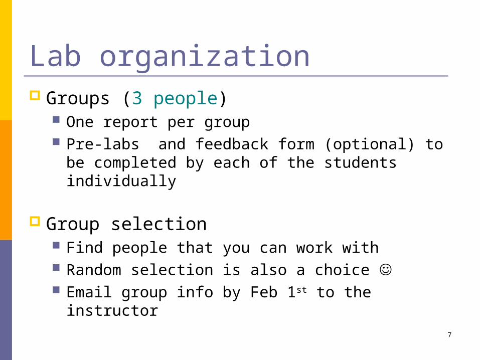
Lab organization Groups (3 people)
One report per group Pre-labs and feedback form (optional) to be
completed by each of the students individually
Group selection Find people that you can work with Random selection is also a choice Email group info by Feb 1st to the instructor

8
Structure of the labs Each lab has four parts:
1. Prelab (individual)2. Lab session (group)3. Lab report (group)4. Feedback forms (individual – optional)
9
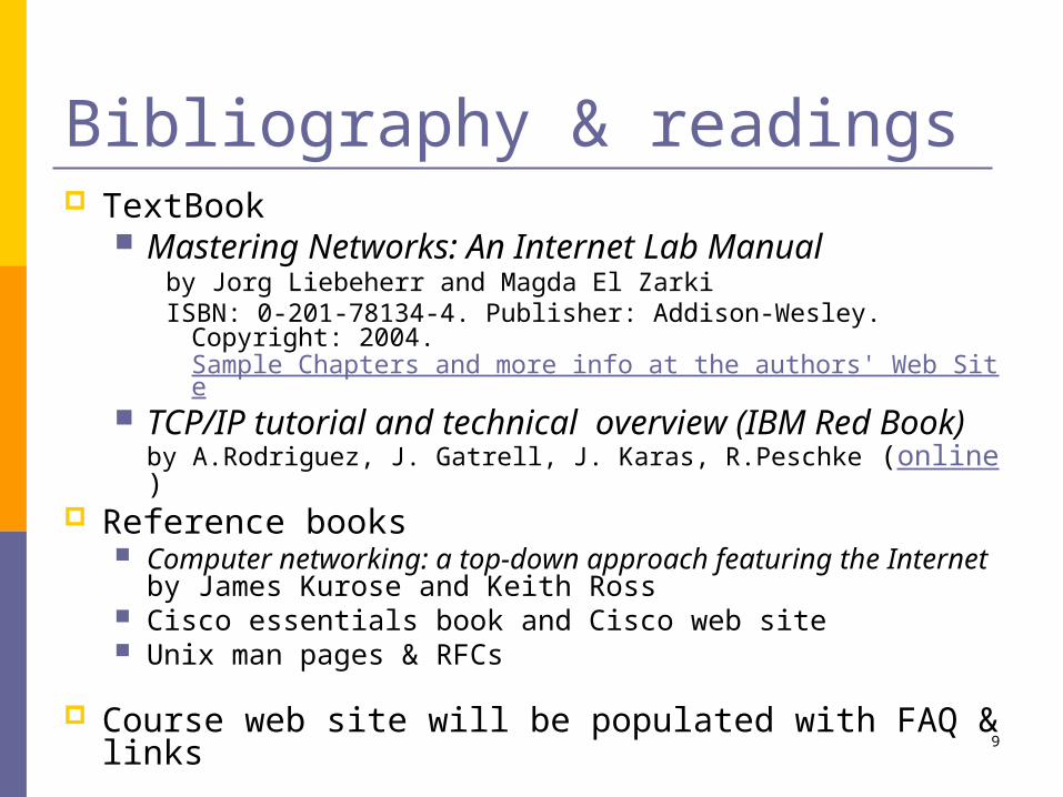
Bibliography & readings TextBook
Mastering Networks: An Internet Lab Manualby Jorg Liebeherr and Magda El ZarkiISBN: 0-201-78134-4. Publisher: Addison-Wesley. Copyright:
2004.Sample Chapters and more info at the authors' Web Site
TCP/IP tutorial and technical overview (IBM Red Book)by A.Rodriguez, J. Gatrell, J. Karas, R.Peschke (online)
Reference books Computer networking: a top-down approach featuring
the Internet by James Kurose and Keith Ross Cisco essentials book and Cisco web site Unix man pages & RFCs
Course web site will be populated with FAQ & links

10
Grading scheme Pre-lab questions: (20%) (individual)
Lab Reports (40%) (group)
Two exams, each 15% (30%) (individual) Final exam can be replaced by a group project
Class participation (5%) (individual)Lab participation (5%) (individual)(TAs may randomly ask a group member any question related to the lab)

11
Other requirements CS account
through CRF Swipe access
MICE Facilities->Card Access->Request Access
Level 6 Sponsor: Salman Baset End date: May 15, 2008
USB flash drive One per group

12
Website, discussion board Website
http://www1.cs.columbia.edu/~salman/4140/
Discussion board, grades, prelab/lab report submissionshttp://courseworks.columbia.edu

13
Agenda Administrivia Introduction to the lab equipment A simple TCP/IP example Overview of important networking
concepts
14
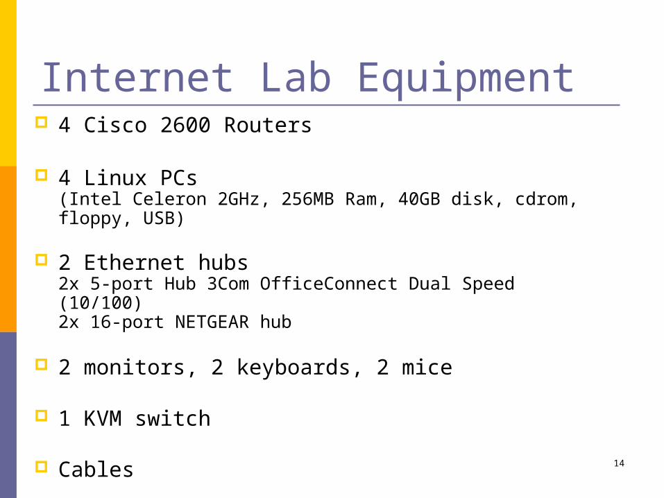
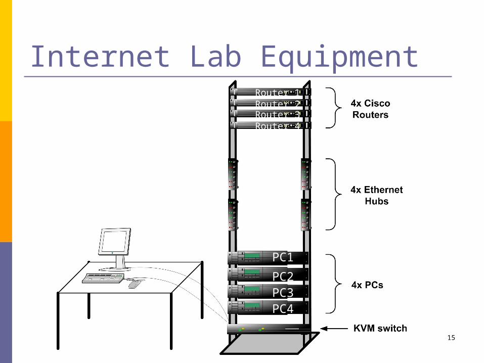
Internet Lab Equipment 4 Cisco 2600 Routers
4 Linux PCs(Intel Celeron 2GHz, 256MB Ram, 40GB disk, cdrom, floppy, USB)
2 Ethernet hubs2x 5-port Hub 3Com OfficeConnect Dual Speed (10/100)2x 16-port NETGEAR hub
2 monitors, 2 keyboards, 2 mice
1 KVM switch
Cables
15
Internet Lab Equipment
PC1
PC2PC3PC4
Router 1Router 2Router 3Router 4

16
Linux PCs PCs and routers are labeled as:
PC1, PC2, etc, Router1, Router2, etc.
PCs run Linux Fedora Core 5
Each PC has: a floppy drive, a cdrom drive, a serial port, 5x 10/100 Mbps Ethernet
interface cards (NICs) named eth0 – eth4. 2x USB ports

17
Linux PC

18
Cisco Routers Routers are labeled: Router1, Router2, Router3,
Router4. Routers run Cisco IOS 12.0 or a later version Each router has:
a console port an auxiliary port two 10/100 Mbps Fast Ethernet interfaces
19
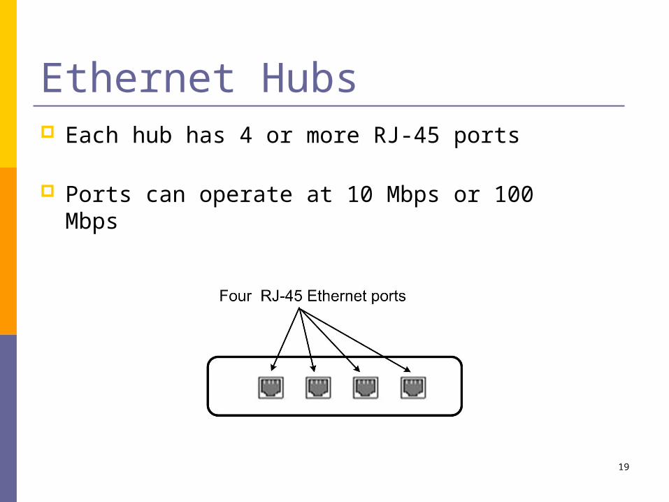
Ethernet Hubs Each hub has 4 or more RJ-45 ports
Ports can operate at 10 Mbps or 100 Mbps

20
Connectors DB-9 (DE-9) connector
(serial port)
PS2 Mini DIN 6
DB-25 connector
DE-15/HD-15(VGA connector)
RJ-45 connector
male female

21
Ethernet Cables Category 5e cable (4 pairs) Straight cable Cross over cable Automatic roll over NICs

22
Lab Sequence
Core Labs:
Lab 2 - SingleSegment IPNetworks
Lab 1 -Introduction to
the Internet Lab
Lab 3 - StaticRouting
Lab 4 -DynamicRouting
Protocols
Lab 5 -TransportProtocols:
UDP and TCP
Advanced Labs:
Lab 7 - NATand DHCP
Lab 6 - LANswitching
Lab 8 - DomainName System
Lab 9 - SNMPLab 10 - IPMulticast

23
Core Labs Lab 1 – Introduction to the Internet Lab
Overview of the Internet Lab equipment; introduction to ethereal and tcpdump.
Lab 2 – Single Segment IP Networks
Configuring a network interface for IP networking; address resolution with ARP;
security problems of common Internet applications.

24
Core Labs (cont.) Lab 3 – Static routing
IP forwarding and routing between IP networks; setup a Linux PC and a Cisco router as an IP router; manual configuration of routing tables.
Lab 4 – Dynamic Routing Protocols Routing protocols RIP, OSPF and BGP.
Lab 5 – Transport Protocols: UDP and TCP
Data transmissions with TCP and UDP; TCP connection management; TCP flow control; retransmissions in TCP; TCP congestion control.

25
Advanced Labs Lab 6 - LAN switching
LAN switching in Ethernet networks; forwarding of Ethernet frames between LAN switches/bridges; spanning tree protocol for loop free routing between interconnected LANs.
Lab 7 - NAT and DHCP Setup of a private network; dynamic assignment of IP addresses with DHCP.
Lab 8 – Domain Name SystemDomain name resolution with DNS; name server hierarchy; setup of a DNS root server.
Lab 10 – IP Multicast Multicast group management with IGMP; IP multicast forwarding; Multicast routing protocols PIM-SM and PIM-DM.

26
In the Lab:1. Submit Prelab through courseworks2. Bring USB drive, the lab manual3. Reboot Linux PCs4. Complete exercises as described in the lab
manual5. Take measurements as instructed 6. Save data to the USB drive7. Submit lab report through courseworks
27
Additional notes The equipment of the Internet Lab is not connected to the
Internet. Warning: Do not connect the lab equipment to the Internet.
Each lab has an anonymous feedback sheet. The feedback is used to improve the setup and organization of the labs.
Since you have administrative (root) privileges on the Internet Lab equipment, exercise caution when modifying the configuration of the Internet Lab equipment.
No eating or drinking in the lab.
Bring your laptops to the lab.
28
Tips for the lab Ethereal is your best friend in 4140!
Each lab session comprises of several [sometimes independent] exercises. Discuss with your group members if you can do the exercise in parallel.
Traffic does not flow! the power is on? connected to the correct interface? interface LED? ethernet wire is behaving correctly? ARP and routing tables? are you observing traffic on the correct interface?

29
Agenda Administrivia Introduction to the lab equipment A simple TCP/IP example Overview of important networking
concepts

30
TopologyWeb request
Web page
A user on host argon.netlab.edu (“Argon”) makes web access to URL http://neon.netlab.edu/index.html.
What actually happens in the network?
Web client Web server

31
HTTP Request and HTTP response
Web server runs an HTTP server program HTTP client Web browser runs an HTTP client
program sends an HTTP request to HTTP server HTTP server responds with HTTP response

32
HTTP Request
GET /example.html HTTP/1.1
Accept: image/gif, */*
Accept-Language: en-us
Accept-Encoding: gzip, deflate
User-Agent: Mozilla/4.0
Host: 192.168.123.144
Connection: Keep-Alive

33
HTTP ResponseHTTP/1.1 200 OK
Date: Sat, 25 May 2002 21:10:32 GMT
Server: Apache/1.3.19 (Unix)
Last-Modified: Sat, 25 May 2002 20:51:33 GMT
ETag: "56497-51-3ceff955"
Accept-Ranges: bytes
Content-Length: 81
Keep-Alive: timeout=15, max=100
Connection: Keep-Alive
Content-Type: text/html
<HTML>
<BODY>
<H1>Internet Lab</H1>
Click <a href="http://www.netlab.net/index.html">here</a> for the Internet Lab webpage.
</BODY>
</HTML>
• How does the HTTP request get from Argon to Neon ?

34
From HTTP to TCP
To send request, HTTP client program establishes an TCP connection to the HTTP server Neon.
The HTTP server at Neon has a TCP server running
HTTP client
TCP client
Argon
HTTP server
TCP server
Neon
HTTP request / HTTP response
TCP connection

35
Resolving hostnames and port numbers
Since TCP does not work with hostnames and also would not know how to find the HTTP server program at Neon, two things must happen:
1. The name “neon.netlab.edu” must be translated into a 32-bit IP address.
2. The HTTP server at Neon must be identified by a 16-bit port number.
36
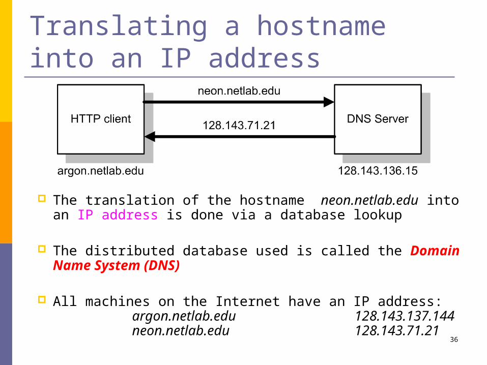
Translating a hostname into an IP address
The translation of the hostname neon.netlab.edu into an IP address is done via a database lookup
The distributed database used is called the Domain Name System (DNS)
All machines on the Internet have an IP address:argon.netlab.edu 128.143.137.144neon.netlab.edu 128.143.71.21

37
Finding the port number Note: Most services on the Internet are reachable via well-known
ports. E.g. HTTP servers on the Internet can be reached at port number
“80”.
So: Argon simply knows the port number of the HTTP server at a remote machine.
On most Unix systems, the well-known ports are listed in a file with name /etc/services. The well-known port numbers of some of the most popular services are:
ftp 21 finger 79telnet 23 http 80smtp 25 nntp 119tftp 69 ssh 23ntp 123
38
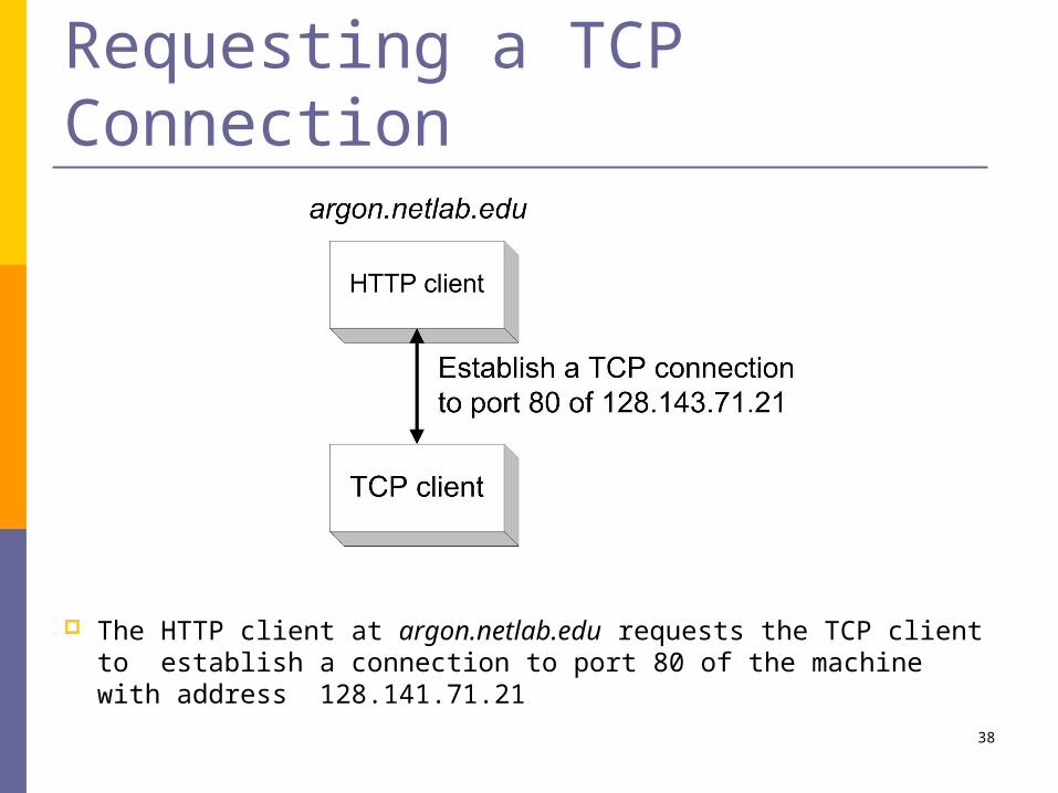
Requesting a TCP Connection
The HTTP client at argon.netlab.edu requests the TCP client to establish a connection to port 80 of the machine with address 128.141.71.21

39
Invoking the IP Protocol
The TCP client at Argon sends a request to establish a connection to port 80 at Neon
This is done by asking its local IP module to send an IP datagram to 128.143.71.21
(The data portion of the IP datagram contains the request to open a connection)

40
Sending the IP datagram to an IP router
Argon (128.143.137.144) can deliver the IP datagram directly to Neon (128.143.71.21), only if it is on the same local network (“subnet”)
But Argon and Neon are not on the same local network (Q: How does Argon know this?)
So, Argon sends the IP datagram to its default gateway
The default gateway is an IP router
The default gateway for Argon is Router137.netlab.edu (128.143.137.1).

41
The route from Argon to Neon
Note that the gateway has a different name for each of its interfaces.
42
Finding the MAC address of the gateway
To send an IP datagram to Router137, Argon puts the IP datagram in an Ethernet frame, and transmits the frame.
However, Ethernet uses different addresses, so-called Media Access Control (MAC) addresses (also called: physical address, hardware address).
Therefore, Argon must first translate the IP address 128.143.137.1 into a MAC address.
The translation of addressed is performed via the Address Resolution Protocol (ARP)

43
Address resolution with ARP

44
Invoking the device driver
The IP module at Argon, tells its Ethernet device driver to send an Ethernet frame to address 00:e0:f9:23:a8:20

45
Sending an Ethernet frame
The Ethernet device driver of Argon sends the Ethernet frame to the Ethernet network interface card (NIC)
The NIC sends the frame onto the wire

46
Forwarding the IP datagram
The IP router receives the Ethernet frame at interface 128.143.137.1, recovers the IP datagram and determines that the IP datagram should be forwarded to the interface with name 128.143.71.1
The IP router determines that it can deliver the IP datagram directly

47
Another lookup of a MAC address
The router needs to find the MAC address of Neon.
Again, ARP is invoked, to translate the IP address of Neon (128.143.71.21) into the MAC address of neon (00:20:af:03:98:28).

48
The IP protocol at Router71, tells its Ethernet device driver to send an Ethernet frame to address 00:20:af:03:98:28
Invoking the Device Driver at the Router
49
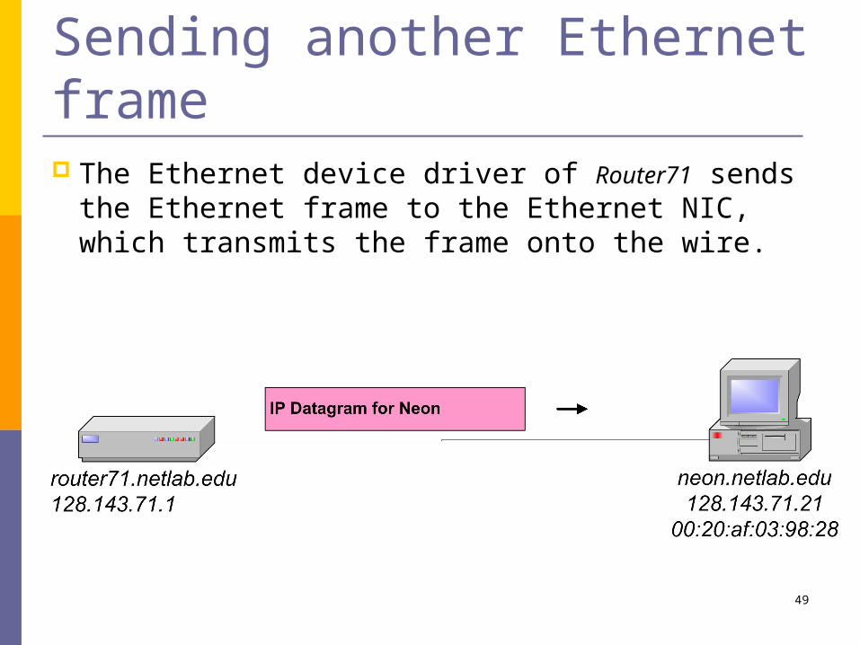
Sending another Ethernet frame The Ethernet device driver of Router71 sends the
Ethernet frame to the Ethernet NIC, which transmits the frame onto the wire.

50
Data has arrived at Neon Neon receives the Ethernet frame
The payload of the Ethernet frame is an IP datagram which is passed to the IP protocol.
The payload of the IP datagram is a TCP segment, which is passed to the TCP server
51
Wrapping up the example Data traverses a sequence of layers
Each layer has protocols to handle the packets

52
Agenda Administrivia Introduction to the lab equipment A simple TCP/IP example Overview of important networking
concepts

53
TCP/IP Suite and OSI Reference Model
ApplicationLayer
ApplicationLayer
PresentationLayer
SessionLayer
TransportLayer
NetworkLayer
(Data) LinkLayer
PhysicalLayer
TransportLayer
NetworkLayer
OSIReference
Model
(Data) LinkLayer
TCP/IP Suite
The TCP/IP protocol stack does not define the lower layers of a complete protocol stack

54
Functions of the Layers Data Link Layer:
Service: Reliable transfer of frames over a linkMedia Access Control on a LAN
Functions: Framing, media access control, error checking
Network Layer: Service: Move packets from source host to destination
host Functions: Routing, addressing
Transport Layer: Service: Delivery of data between hosts Functions: Connection establishment/termination, error
control, flow control Application Layer:
Service: Application specific (delivery of email, retrieval of HTML documents, reliable transfer of file)
Functions: Application specific

55
Assignment of Protocols to Layers
NetworkLayer
Routing Protocols
PIM
OSPF
RIP
ApplicationLayer
Data LinkLayer
IP
ARP Ethernet
NetworkInterface
TransportLayer
TCP UDP
SNMPFTP DNSHTTP
ICMP
IGMP
pingapplication Telnet
DHCP

56
Layered Communications An entity of a particular layer can only
communicate with:1. a peer layer entity using a common protocol (Peer Protocol)2. adjacent layers to provide services and to receive services
N+1 LayerEntity
N+1 LayerEntity
N+1 Layer ProtocolN+1 Layer
N-1 LayerEntity
N-1 LayerEntity
N-1 Layer ProtocolN-1 Layer
N LayerEntity
N LayerEntity
N Layer ProtocolN Layer
layer N+1/Ninterface
layer N/N-1interface

57
Layered Communications
A layer N+1 entity sees the lower layers only as a service provider
Service Provider
N+1 LayerEntity
N+1 LayerEntity
N+1 Layer Peer Protocol
Request Delivery
IndicateDelivery

58
Service Access Points A service user accesses services of the
service provider at Service Access Points (SAPs)
A SAP has an address that uniquely identifies where the service can be accessed Layer-N
EntityN Layer
Layer- N-1Entity
N-1Layer
layer N/N-1service interface
LayerN-1SAP

59
Exchange of Data The unit of data send between peer entities is called a
Protocol Data Unit (PDU) For now, let us think of a PDU as a single packet
Scenario: Layer-N at A sends a layer-N PDU to layer-N at B
What actually happens: A’s layer-N passes the PDU to one the SAPs at layer-N-1 Layer-N-1 entity at A constructs its own (layer-N-1) PDU which it
sends to the layer-N-1 entity at B PDU at layer-N-1 = layer-N-1 Header + layer –N PDU
N LayerEntity
PDU(at layer N)
N LayerEntity
A B

60
Exchange of Data
Layer-NEntity
N PDU
Layer- N-1Entity
Layer-N PDU and control data issent to SAP of Layer-N-1
SAPs
control
N PDUcontrol
Header(of layer N-1) N PDU
PDU of Layer-N-1
Layer-NEntity
Layer- N-1Entity
A B
61
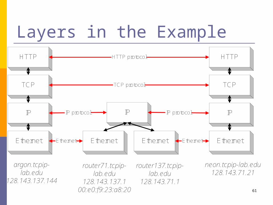
Layers in the ExampleHTTP
TCP
IP
argon.tcpip-lab.edu
128.143.137.144
Ethernet Ethernet Ethernet
IP
HTTP
TCP
IP
neon.tcpip-lab.edu128.143.71.21
Ethernet
router71.tcpip-lab.edu
128.143.137.100:e0:f9:23:a8:20
router137.tcpip-lab.edu
128.143.71.1
HTTP protocol
TCP protocol
IP protocol
Ethernet
IP protocol
Ethernet

62
Layers in the ExampleHTTP
TCP
IP
argon.tcpip-lab.edu
128.143.137.144
Ethernet Ethernet Ethernet
IP
HTTP
TCP
IP
neon.tcpip-lab.edu128.143.71.21
Ethernet
router71.tcpip-lab.edu
128.143.137.100:e0:f9:23:a8:20
router137.tcpip-lab.edu128.143.71.1
Send HTTP Request to neon
Establish a connection to 128.143.71.21 at port 80Open TCP connection to
128.143.71.21 port 80
Send a datagram (which contains a connection request) to 128.143.71.21Send IP datagram to
128.143.71.21
Send the datagram to 128.143.137.1
Send Ethernet frame to 00:e0:f9:23:a8:20
Send Ethernet frame to 00:20:af:03:98:28
Send IP data-gram to 128.143.71.21
Send the datagram to 128.143.7.21
Frame is an IP datagram
Frame is an IP datagram
IP datagram is a TCP segment for port 80

63
Layers and Services Service provided by TCP to HTTP:
reliable transmission of data over a logical connection Service provided by IP to TCP:
unreliable transmission of IP datagrams across an IP network
Service provided by Ethernet to IP: transmission of a frame across an Ethernet segment
Other services: DNS: translation between domain names and IP addresses ARP: Translation between IP addresses and MAC addresses
64
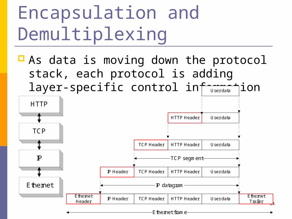
Encapsulation and Demultiplexing As data is moving down the protocol
stack, each protocol is adding layer-specific control informationHTTP
TCP
IP
Ethernet
User data
User dataHTTP Header
TCP Header
TCP HeaderIP Header
TCP HeaderIP HeaderEthernetHeader
EthernetTrailer
IP datagram
TCP segment
Ethernet frame
User dataHTTP Header
User dataHTTP Header
User dataHTTP Header
65
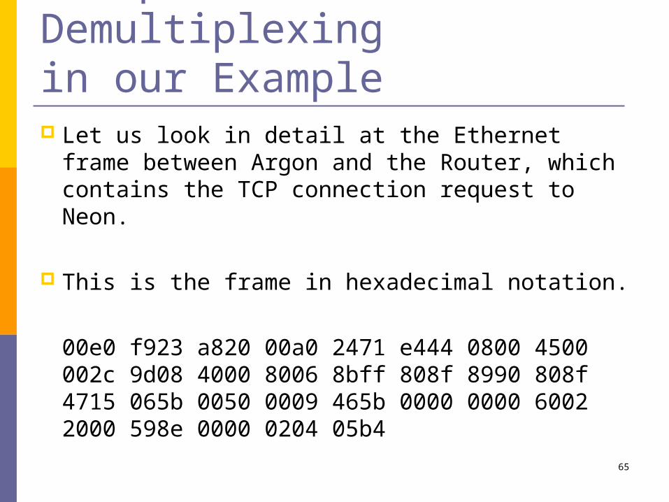
Encapsulation and Demultiplexing in our Example Let us look in detail at the Ethernet frame
between Argon and the Router, which contains the TCP connection request to Neon.
This is the frame in hexadecimal notation.
00e0 f923 a820 00a0 2471 e444 0800 4500 002c 9d08 4000 8006 8bff 808f 8990 808f 4715 065b 0050 0009 465b 0000 0000 6002 2000 598e 0000 0204 05b4
66
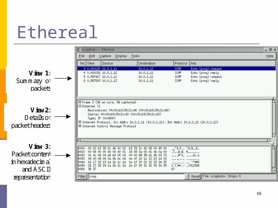
Ethereal
View 1: Summary of
packets
View2: Details of
packet headers
View 3: Packet content in hexadecimal
and ASCII representation

67
Parsing the information in the frame
version0x4
header length
0x5Type of Service/TOS
0x00total length (in bytes)
0x002cIdentification0x9d08
flags0102
fragment offset00000000000002
cource IP address128.143.137.144
destination IP address128.143.71.21
time-to;ive0x80
protocol0x06
header checksum0x8bff
source port number162710
destination port number8010
sequence number0x0009465b
acknowledgement number0x00000000
header length
0x6unused0000002
flags0000102
window size819210
TCP checksum0x598e
urgent pointer0x0000
maximum segment size146010
option type0x02
option length0x04
destination address00:e0:f9:23:a8:20
source address0:a0:24:71:e4:44
type0x0800
4 bytes
CRC
Ethernetheader
(14 bytes)
IP Header(20 bytes)
TCP Header(24 bytes)
Ethernettrailer
(4 bytes)

68
Encapsulation and Demultiplexing
Application dataTCP HeaderIP HeaderEthernet Header Ethernet Trailer
Ethernet frame
destination address
source address
type
6 bytes
CRC
4 bytes

69
00:e0:f9:23:a8:20
0:a0:24:71:e4:44
0x0800
6 bytes
CRC
4 bytes
Encapsulation and Demultiplexing:
Ethernet Header
Application dataTCP HeaderIP HeaderEthernet Header Ethernet Trailer
Ethernet frame

70
Encapsulation and Demultiplexing:
IP Header
Application dataTCP HeaderEthernet Header Ethernet Trailer
Ethernet frame
IP Header
DS ECNversion(4 bits)
headerlength
Total Length (in bytes)(16 bits)
Identification (16 bits)flags
(3 bits)Fragment Offset (13 bits)
Source IP address (32 bits)
Destination IP address (32 bits)
TTL Time-to-Live(8 bits)
Protocol(8 bits)
Header Checksum (16 bits)
32 bits

71
Encapsulation and Demultiplexing:
IP Header
Application dataTCP HeaderEthernet Header Ethernet Trailer
Ethernet frame
IP Header
0x0 0x00x4 0x5 4410
9d08 0102 00000000000002
128.143.137.144
128.143.71.21
12810 0x06 8bff
32 bits

72
Encapsulation and Demultiplexing:
TCP Header
Application dataEthernet Header Ethernet Trailer
Ethernet frame
IP Header TCP Header
Sequence number (32 bits)
Source Port Number Destination Port Number
Acknowledgement number (32 bits)
window sizeheaderlength
0 Flags
TCP checksum urgent pointer
32 bits
length Max. segment sizeoptiontype
Option: maximum segment size

73
Encapsulation and Demultiplexing:
TCP Header
Application dataEthernet Header Ethernet Trailer
Ethernet frame
IP Header TCP Header
60783510
162710 8010
010
819210610 0000002 0000102
0x598e 00002
32 bits
410 146010210

74
Encapsulation and Demultiplexing: Application data
Application dataEthernet Header Ethernet Trailer
Ethernet frame
IP Header TCP Header
No Application Data
in this frame

75
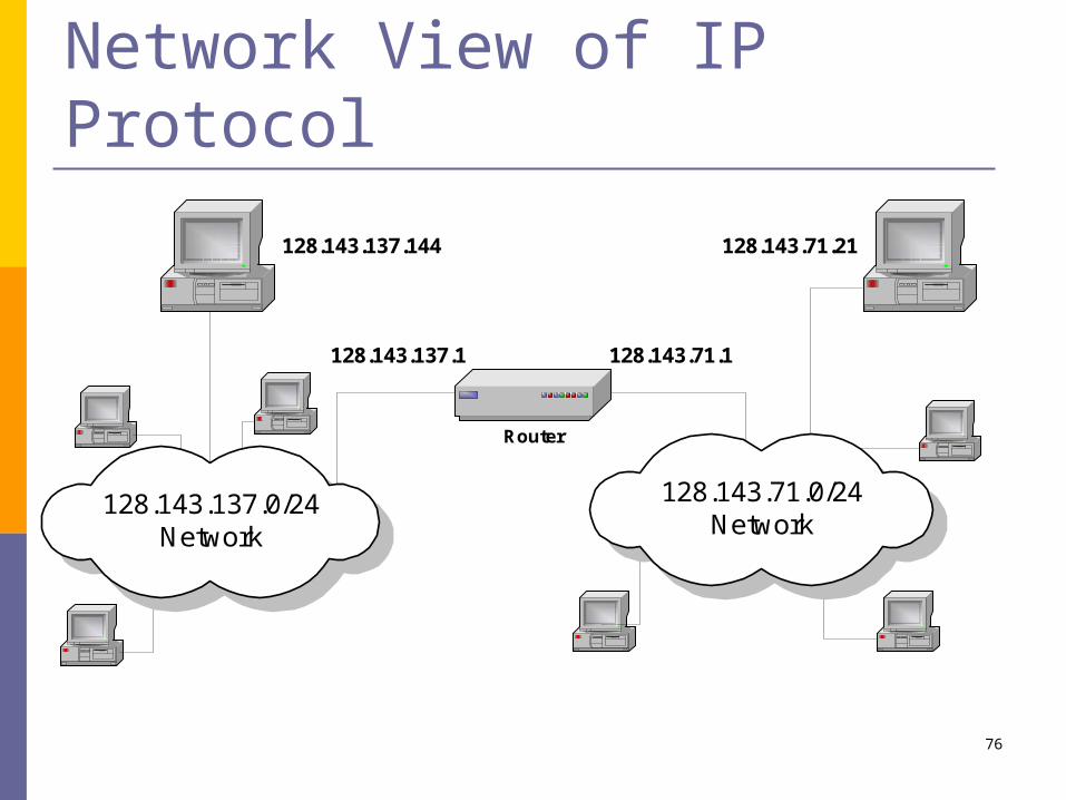
Different Views of Networking Different Layers of the protocol stack have a
different view of the network. This is HTTP’s and TCP’s view of the network.
HTTP client
TCP client
Argon128.143.137.144
HTTPserver
TCP server
Neon128.143.71.21
IP Network
HTTPserver
TCP server
76
Network View of IP Protocol
128.143.71.21128.143.137.144
Router
128.143.137.0/24Network
128.143.137.1 128.143.71.1
128.143.71.0/24Network

77
Network View of Ethernet Ethernet’s view of the network
Argon(128.143.137.144)
Router137(128.143.137.1)
Ethernet Network

78
What a router chassis looks likeCisco CRS-1 Juniper M320
6ft
19”
2ft
Capacity: 1.2 Tb/sPower: 10.92 KWh Weight: 0.5 TonCost: $500K
3ft
2ft
17”
Capacity: 320 Gb/s Power: 3.1 kWh

79
Cisco CRS-1

80
Next week Lab 1 & 2 Submit prelab 1 & 2 through courseworks Apply for swipe access Form a group Bring a USB drive
Reading Chapter 0, p1-25, 45-71 Optional: IBM red book, chapter 1.


