ComputerVoltageSource Synthesizer · PDF fileDavid. J Brown September 22, 2007...
15
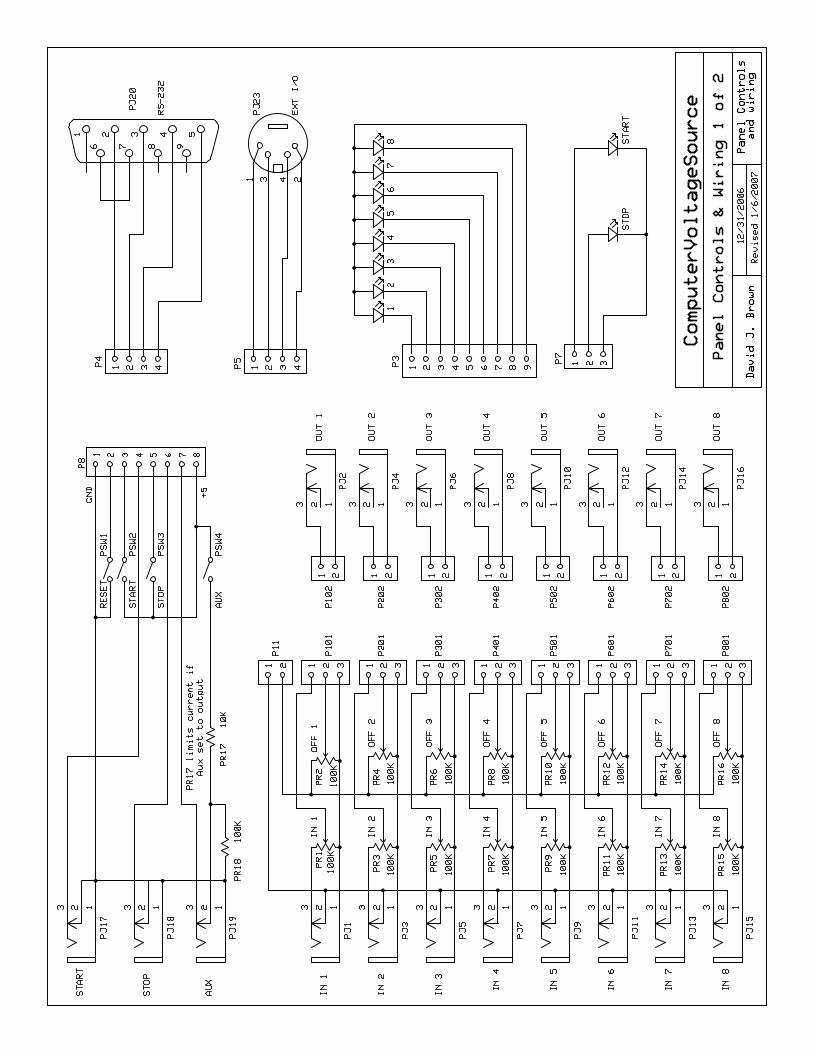
ComputerVoltageSource Synthesizer Module David J. Brown 7/24/2007 Adapted and modified from a design by Grant Richter with contributions by John Loffink and Harry Bissell Module Features: • BasicMicro AtomPro28 processor • 2 Kbytes ram • 31 Kbytes program flash memory • 256 bytes non-volatile eeprom • Eight 0 to 10 volt analog inputs (each input calibrated to ADC max value 1023) • Input attenuator controls normalled to 10 volts • Each input is summed with a 0 to 5 volt offset control for +/- 5 volt input levels • Programmable reference voltages • Allow each bank of attenuator and offset controls to be read independently • All 16 controls can be used in applications such as a sequencer • Eight 0 to 10.666 volt analog outputs and indicator LEDs • Start input, switch, and indicator LED • Stop input, switch, and indicator LED • Aux output or input and switch • Over / under voltage protection on all inputs and outputs • MIDI input, output, and indicator LED (interrupt 128 byte buffers) • External I/O connector for additional input and output expandability (100 Kbit I2C interface with power) • RS-232 computer programming port • Reset switch • PSIM software compatible (outputs 5-8 mirror outputs 1-4) • 2 row x 16 character LCD with eight programmable 5x7 characters • +15 volts at 130 to 190 mA, depending on the brightness of the LEDs and LCD backlight • -15 volts at 28 mA External Controls Module
Transcript of ComputerVoltageSource Synthesizer · PDF fileDavid. J Brown September 22, 2007...

ComputerVoltageSource Synthesizer Module David J. Brown 7/24/2007
Adapted and modified from a design by Grant Richter with contributions by John Loffink and Harry Bissell Module Features:
• BasicMicro AtomPro28 processor • 2 Kbytes ram • 31 Kbytes program flash memory • 256 bytes non-volatile eeprom
• Eight 0 to 10 volt analog inputs (each input calibrated to ADC max value 1023) • Input attenuator controls normalled to 10 volts • Each input is summed with a 0 to 5 volt offset control for +/- 5 volt input levels
• Programmable reference voltages • Allow each bank of attenuator and offset controls to be read independently • All 16 controls can be used in applications such as a sequencer
• Eight 0 to 10.666 volt analog outputs and indicator LEDs • Start input, switch, and indicator LED • Stop input, switch, and indicator LED • Aux output or input and switch • Over / under voltage protection on all inputs and outputs • MIDI input, output, and indicator LED (interrupt 128 byte buffers) • External I/O connector for additional input and output expandability (100 Kbit I2C interface with power) • RS-232 computer programming port • Reset switch • PSIM software compatible (outputs 5-8 mirror outputs 1-4) • 2 row x 16 character LCD with eight programmable 5x7 characters • +15 volts at 130 to 190 mA, depending on the brightness of the LEDs and LCD backlight • -15 volts at 28 mA
External Controls Module


Ver
sion
5/1
6/07
P
age
1 of
1

Com
pute
rVol
tage
Sou
rce
Mai
n P
CB
V
ersi
on 5
/16/
07
Page 1ComputerVoltageSources
02/18/2008 10:12:13 AMhttp://launch.groups.yahoo.com/group/ComputerVoltageSources/database?method=repo...
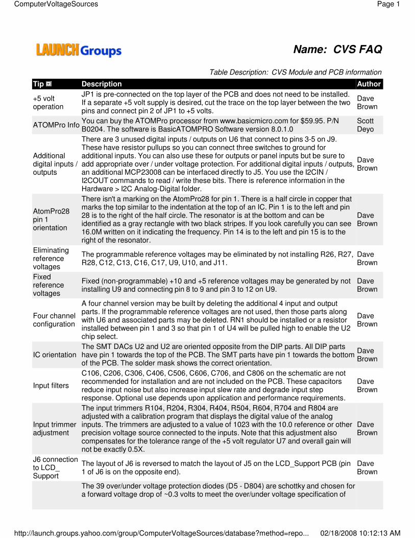
Name: CVS FAQ
Table Description: CVS Module and PCB information
Tip Description Author
+5 voltoperation
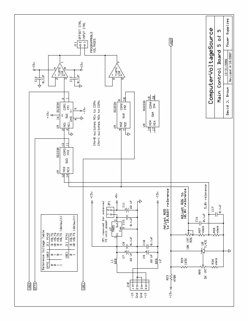
JP1 is pre-connected on the top layer of the PCB and does not need to be installed.If a separate +5 volt supply is desired, cut the trace on the top layer between the twopins and connect pin 2 of JP1 to +5 volts.
DaveBrown
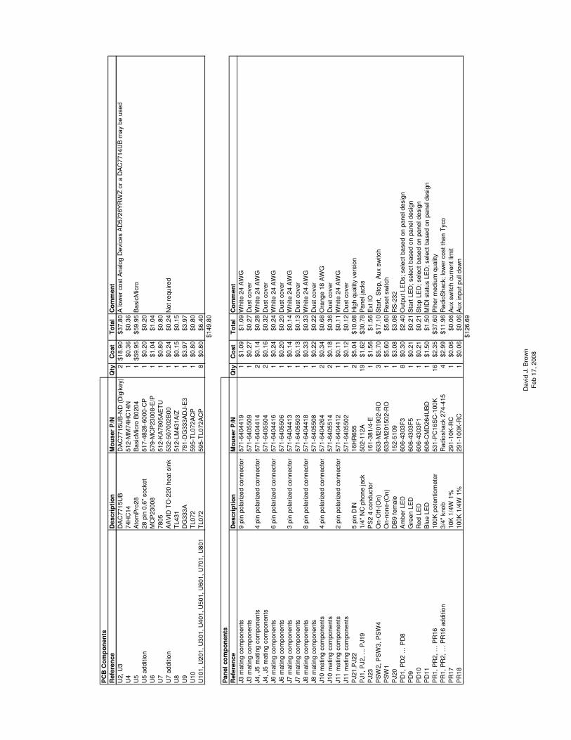
ATOMPro Info You can buy the ATOMPro processor from www.basicmicro.com for $59.95. P/NB0204. The software is BasicATOMPRO Software version 8.0.1.0
ScottDeyo
Additionaldigital inputs /outputs
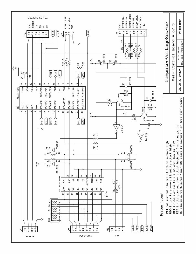
There are 3 unused digital inputs / outputs on U6 that connect to pins 3-5 on J9.These have resistor pullups so you can connect three switches to ground foradditional inputs. You can also use these for outputs or panel inputs but be sure toadd appropriate over / under voltage protection. For additional digital inputs / outputs,an additional MCP23008 can be interfaced directly to J5. You use the I2CIN /I2COUT commands to read / write these bits. There is reference information in theHardware > I2C Analog-Digital folder.
DaveBrown
AtomPro28pin 1orientation
There isn't a marking on the AtomPro28 for pin 1. There is a half circle in copper thatmarks the top similar to the indentation at the top of an IC. Pin 1 is to the left and pin28 is to the right of the half circle. The resonator is at the bottom and can beidentified as a gray rectangle with two black stripes. If you look carefully you can see16.0M written on it indicating the frequency. Pin 14 is to the left and pin 15 is to theright of the resonator.
DaveBrown
Eliminatingreferencevoltages
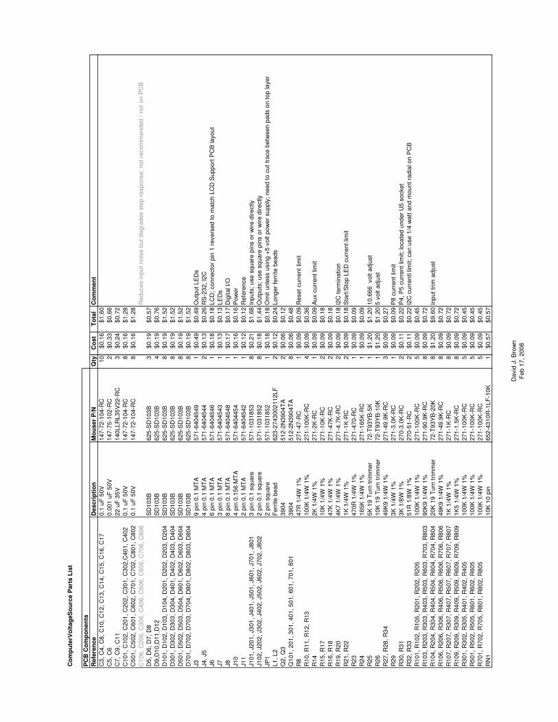
The programmable reference voltages may be eliminated by not installing R26, R27,R28, C12, C13, C16, C17, U9, U10, and J11.
DaveBrown
Fixedreferencevoltages
Fixed (non-programmable) +10 and +5 reference voltages may be generated by notinstalling U9 and connecting pin 8 to 9 and pin 3 to 12 on U9.
DaveBrown
Four channelconfiguration
A four channel version may be built by deleting the additional 4 input and outputparts. If the programmable reference voltages are not used, then those parts alongwith U6 and associated parts may be deleted. RN1 should be installed or a resistorinstalled between pin 1 and 3 so that pin 1 of U4 will be pulled high to enable the U2chip select.
DaveBrown
IC orientationThe SMT DACs U2 and U2 are oriented opposite from the DIP parts. All DIP partshave pin 1 towards the top of the PCB. The SMT parts have pin 1 towards the bottomof the PCB. The solder mask shows the correct orientation.
DaveBrown
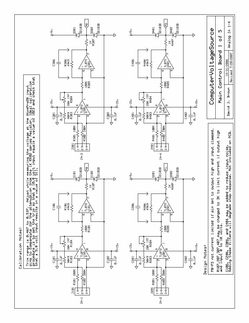
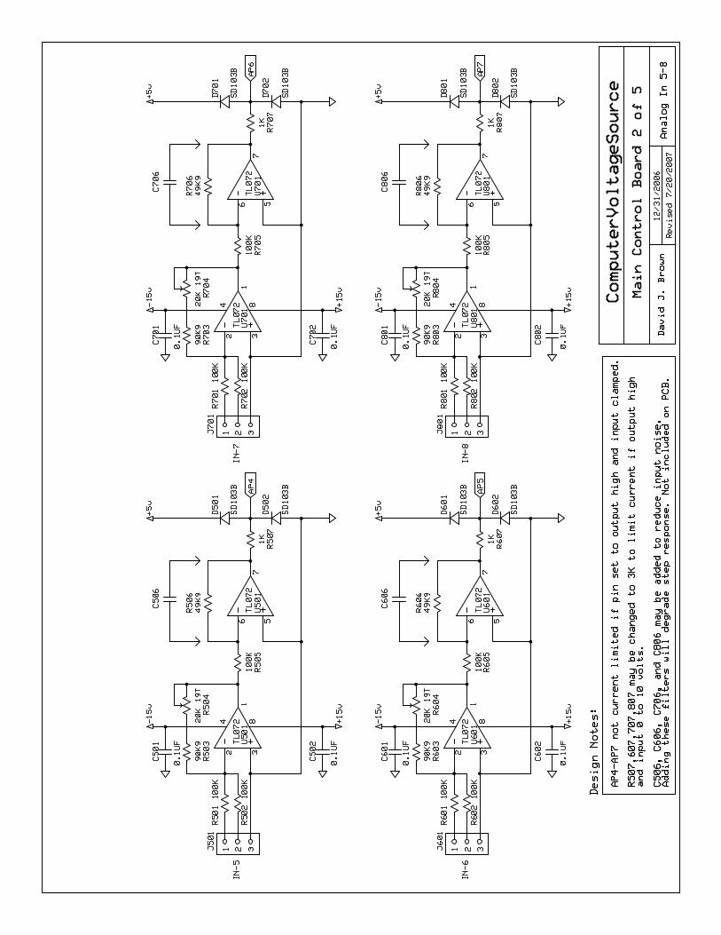
Input filters
C106, C206, C306, C406, C506, C606, C706, and C806 on the schematic are notrecommended for installation and are not included on the PCB. These capacitorsreduce input noise but also increase input slew rate and degrade input stepresponse. Optional use depends upon application and performance requirements.
DaveBrown
Input trimmeradjustment
The input trimmers R104, R204, R304, R404, R504, R604, R704 and R804 areadjusted with a calibration program that displays the digital value of the analoginputs. The trimmers are adjusted to a value of 1023 with the 10.0 reference or otherprecision voltage source connected to the inputs. Note that this adjustment alsocompensates for the tolerance range of the +5 volt regulator U7 and overall gain willnot be exactly 0.5X.
DaveBrown
J6 connectionto LCD_Support
The layout of J6 is reversed to match the layout of J5 on the LCD_Support PCB (pin1 of J6 is on the opposite end).
DaveBrown
The 39 over/under voltage protection diodes (D5 - D804) are schottky and chosen fora forward voltage drop of ~0.3 volts to meet the over/under voltage specification of

Page 2ComputerVoltageSources
02/18/2008 10:12:13 AMhttp://launch.groups.yahoo.com/group/ComputerVoltageSources/database?method=repo...
the Renesas H8/3664 processor. Other diodes with similar specifications may beused.
R25 and R26adjustment
Adjust R25 to calibrate the 10.666 volts as measured at the end of R23 closest to U8.Then adjust R26 to calibrate the 10.000 volts as measured at pin 9 of U9. Check pin12 of U9 to be close to 5.0 volts.
DaveBrown
R30 and R31resistors
R30 and R31 limit current if the AtomPro P4 and P5 are set to outputs. 1/8 wattresistors were used for board space requirements and were placed inside the U5socket footprint. The socket footprint must allow room for these components. Theresistors may also be installed on the bottom side of the PCB or simply replaced withjumper wires.
DaveBrown
R32 and R33resistors
R32 and R33 limit current for I2C over/under voltage. 1/8 watt resistors were used forboard space requirements. 1/4 watt resistors may be used if mounted radially. Valuesmay be changed depending on application.
DaveBrown
Reset currentlimit
R8 is very important to install. The AtomPro28 has an active power-on-reset circuitand grounding the reset pin shorts the output of this circuit. R8 limits the short circuitcurrent.
DaveBrown
SMTsoldering
Here's how I solder the SMT DACs: First, use a very fine point tip (photo in the "Files> Hardware > CVS Module" folder). Then align the DAC on the PCB and use a pieceof masking tape to hold it in place. The part needs to be aligned in both directions(horizontal and vertical). Use a magnifying glass to really see where it is placed. Thenuse fine solder and solder one corner pin. Remove the masking tape and solder theopposite corner pin. There is a bit of compliance in the pins so you can adjust theDAC to align the pin dead center on the pad. Then reflow the first pin and adjust theDAC to align that pin dead center on the pad. Now use the magnifier to check thealignment on all 16 pins. Solder each pin using fine solder. Then recheck each pinwith a magnifier to make sure the solder flowed. If you have a bridge you can removethe excess solder with solder wick.
DaveBrown
Transistororientation
Transistors Q101 – Q801 are not all oriented the same direction. Q301, Q401, Q701,and Q801 are oriented opposite from Q101, Q201, Q501, and Q601.
DaveBrown

David. J Brown September 22, 2007
ComputerVoltageSource Build Sequence You can build the ComputerVoltageSource in a four step sequence. Group A: Power Supplies 1. Install all components on page 5 and RN1 on page 4. 2. Verify +15 volts at J3 pin 9. 3. Verify -15 volts at U10 pin 4. 4. Verify +5 volts at J8 pin 8. 5. Adjust R25 for +10.666 volts at the top of R23, just below U8. 6. Adjust R26 for +10.0 volts at J11 pin 1. 7. Check for approximately +5 volts at J11 pin 2. 8. Recheck R25 for +10.666 volts at the top of R23, just below U8. 9. Recheck R26 for +10.0 volts at J11 pin 1. Group B: Digital I/O 10. Install all components on page 4 except U6. The default program in the AtomPro28
should blink the Start and Stop LEDs. If not, proceed to step 11. 11. Connect RS-232 to J4. Program the AtomPro28. Make sure the BasicMicro IDE is
set to Auto or AtomPro28. You can use the “cvs display inputs (rev0.1).djb.bas”, “cvs test waveforms (rev0.0).djb.bas”, or any PSIM program.
Group C: Analog Outputs 12. Install all components on page 3 and U6 on page 4. 13. Connect the LCD_Support PCB to J6. The ComputerVoltageSource now has full
MIDI, LCD Display, and 8 analog output functionality. If you used the “cvs display inputs (rev0.1).djb.bas” or “cvs test waveforms (rev0.0).djb.bas” programs you will see the program name or values displayed on the LCD.
Group D: Analog Inputs 14. Install all components on pages 1 and 2. 15. Program the AtomPro28 with the “cvs display inputs (rev0.1).djb.bas” program.
Connect the 10.0 reference voltage source to each input. The display will show the IN1 to IN4 values in the format "I1=XXXX I2=XXXX I3=XXXX I4=XXXX ". Adjust the IN1 to IN4 input trimmers to a value of 1023.
16. Depress the start switch to toggle to IN5 to IN8. Adjust the IN5 to IN8 input trimmers
to a value of 1023. Congratulations. Your ComputerVoltageSource is built and calibrated.