Computer Vision in Automated Parking Systems: Design ...
14
Computer Vision in Automated Parking Systems: Design, Implementation and Challenges Markus Heimberger a , Jonathan Horgan b , Ciaran Hughes b , John McDonald b , Senthil Yogamani b,* a Automated Parking Product Segment, Valeo Schalter Und Sensoren, Bietigheim, Germany b Automated Parking Product Segment, Valeo Vision Systems, Tuam, Ireland Abstract Automated driving is an active area of research in both industry and academia. Automated Parking, which is automated driving in a restricted scenario of parking with low speed manoeuvring, is a key enabling product for fully autonomous driving systems. It is also an important milestone from the perspective of a higher end system built from the previous generation driver assistance systems comprising of collision warning, pedestrian detection, etc. In this paper, we discuss the design and implementation of an automated parking system from the perspective of computer vision algorithms. Designing a low-cost system with functional safety is challenging and leads to a large gap between the prototype and the end product, in order to handle all the corner cases. We demonstrate how camera systems are crucial for addressing a range of automated parking use cases and also, to add robustness to systems based on active distance measuring sensors, such as ultrasonics and radar. The key vision modules which realize the parking use cases are 3D reconstruction, parking slot marking recognition, freespace and vehicle/pedestrian detection. We detail the important parking use cases and demonstrate how to combine the vision modules to form a robust parking system. To the best of the authors’ knowledge, this is the first detailed discussion of a systemic view of a commercial automated parking system. Keywords: Automated Parking, Automotive Vision, Autonomous Driving, ADAS, Machine Learning, Computer Vision, Embedded Vision, Safety critical systems 1. Introduction Cameras have become ubiquitous in cars, with a rear-view camera being the minimum and full surround view camera sys- tems at the top-end. Automotive camera usage began with sin- gle viewing camera systems for the driver. However, both the number of cameras and the number of ADAS applications made possible with automotive cameras have increased rapidly in the last five years, mainly due to the fact that the processing power has increased during this time period to enable the high levels of real-time processing for computer vision functions. Some ex- amples include applications such as back-over protection, lane departure warning, front-collision warning, or stereo cameras for more complete depth estimation of the environment ahead of the vehicle. The next level of advanced systems require driving automation in certain scenarios like highway or park- ing situations. There are many levels of autonomous 1 driving as defined by Society of Automotive Engineers [1]. Fully au- tonomous driving (Level 5) is an ambitious goal. The current systems are, at best, Level 3 and the commercial deployment is mainly for highway driving. In this paper, we focus on Level 2 or Level 3 type automated parking systems. * Authors are listed in alphabetical order. Corresponding author’s contact is Email address: [email protected] (Senthil Yogamani) 1 The words autonomous and automated are used interchangeably by re- searchers in both industry and academia. In this paper, we use the term au- tomated instead of autonomous implying that the system is not completely in- dependent and there is a driver trigger. CMS CMS SV ACC PD FCW CTA CTA BSD LD LD BSD TSR LD RCW PA BOP PD CTA CTA ACC – Active Cruise Control BOP – Back Over Protection BSD – Blind Spot Detection CMS – Camera Monitoring System CTA – Cross Traffic Alert FCW – Front Collision Warning LD – Lane Detection PA – Parking Assist PD – Pedestrian Detection RCW – Rear Collision Warning SV – Surround View TSR – Traffic Sign Recognition Figure 1: Camera based ADAS applications and their respective field of view Certainly there are risks involved as no algorithm is perfect, and the sensors utilized can have limitations in certain scenar- ios. Automated parking is a good commercial starting point to deploy automated driving in a more restricted environment. Firstly, it involves low speed manoeuvring with a low risk of high impact accidents. Secondly, it is a more controlled envi- ronment with fewer scene variations and corner cases. Stable deployment of automated parking in the real world and analy- sis of performance statistics is an important step towards going to higher levels of autonomy. The first generation parking systems were semi-automated using ultrasonics or radar. Cameras are recently augmenting them to provide a more robust and versatile solution. In this paper, we consider cameras as an important component of a parking system, extending the capabilities of or providing inex- pensive alternatives to other sensors. Figure 1 shows the var- Preprint submitted to Image and Vision Computing April 27, 2021 arXiv:2104.12537v1 [cs.CV] 26 Apr 2021
Transcript of Computer Vision in Automated Parking Systems: Design ...

Computer Vision in Automated Parking Systems: Design, Implementation and Challenges
Markus Heimbergera, Jonathan Horganb, Ciaran Hughesb, John McDonaldb, Senthil Yogamanib,∗
aAutomated Parking Product Segment, Valeo Schalter Und Sensoren, Bietigheim, GermanybAutomated Parking Product Segment, Valeo Vision Systems, Tuam, Ireland
Abstract
Automated driving is an active area of research in both industry and academia. Automated Parking, which is automated drivingin a restricted scenario of parking with low speed manoeuvring, is a key enabling product for fully autonomous driving systems.It is also an important milestone from the perspective of a higher end system built from the previous generation driver assistancesystems comprising of collision warning, pedestrian detection, etc. In this paper, we discuss the design and implementation ofan automated parking system from the perspective of computer vision algorithms. Designing a low-cost system with functionalsafety is challenging and leads to a large gap between the prototype and the end product, in order to handle all the corner cases.We demonstrate how camera systems are crucial for addressing a range of automated parking use cases and also, to add robustnessto systems based on active distance measuring sensors, such as ultrasonics and radar. The key vision modules which realize theparking use cases are 3D reconstruction, parking slot marking recognition, freespace and vehicle/pedestrian detection. We detailthe important parking use cases and demonstrate how to combine the vision modules to form a robust parking system. To the bestof the authors’ knowledge, this is the first detailed discussion of a systemic view of a commercial automated parking system.
Keywords: Automated Parking, Automotive Vision, Autonomous Driving, ADAS, Machine Learning, Computer Vision,Embedded Vision, Safety critical systems
1. Introduction
Cameras have become ubiquitous in cars, with a rear-viewcamera being the minimum and full surround view camera sys-tems at the top-end. Automotive camera usage began with sin-gle viewing camera systems for the driver. However, both thenumber of cameras and the number of ADAS applications madepossible with automotive cameras have increased rapidly in thelast five years, mainly due to the fact that the processing powerhas increased during this time period to enable the high levels ofreal-time processing for computer vision functions. Some ex-amples include applications such as back-over protection, lanedeparture warning, front-collision warning, or stereo camerasfor more complete depth estimation of the environment aheadof the vehicle. The next level of advanced systems requiredriving automation in certain scenarios like highway or park-ing situations. There are many levels of autonomous 1 drivingas defined by Society of Automotive Engineers [1]. Fully au-tonomous driving (Level 5) is an ambitious goal. The currentsystems are, at best, Level 3 and the commercial deployment ismainly for highway driving. In this paper, we focus on Level 2or Level 3 type automated parking systems.
∗Authors are listed in alphabetical order. Corresponding author’s contact isEmail address: [email protected] (Senthil
Yogamani)1The words autonomous and automated are used interchangeably by re-
searchers in both industry and academia. In this paper, we use the term au-tomated instead of autonomous implying that the system is not completely in-dependent and there is a driver trigger.
CMS
CMS
SV
ACCPD
FCW
CTA
CTA
BSDLD
LDBSD
TSR LD
RCW
PA
BOPPD
CTA
CTA
ACC – Active Cruise ControlBOP – Back Over ProtectionBSD – Blind Spot DetectionCMS – Camera Monitoring SystemCTA – Cross Traffic AlertFCW – Front Collision WarningLD – Lane DetectionPA – Parking AssistPD – Pedestrian DetectionRCW – Rear Collision WarningSV – Surround ViewTSR – Traffic Sign Recognition
Figure 1: Camera based ADAS applications and their respective field of view
Certainly there are risks involved as no algorithm is perfect,and the sensors utilized can have limitations in certain scenar-ios. Automated parking is a good commercial starting pointto deploy automated driving in a more restricted environment.Firstly, it involves low speed manoeuvring with a low risk ofhigh impact accidents. Secondly, it is a more controlled envi-ronment with fewer scene variations and corner cases. Stabledeployment of automated parking in the real world and analy-sis of performance statistics is an important step towards goingto higher levels of autonomy.
The first generation parking systems were semi-automatedusing ultrasonics or radar. Cameras are recently augmentingthem to provide a more robust and versatile solution. In thispaper, we consider cameras as an important component of aparking system, extending the capabilities of or providing inex-pensive alternatives to other sensors. Figure 1 shows the var-
Preprint submitted to Image and Vision Computing April 27, 2021
arX
iv:2
104.
1253
7v1
[cs
.CV
] 2
6 A
pr 2
021

ious field of views of common ADAS applications [2], someof which is needed for parking systems. Typically, surroundview camera systems consist of four sensors forming a networkwith small overlap regions, sufficient to cover the near field areaaround the car. Figure 2 shows the four views of a typical cam-era network such as this. It is important to note that the camerasare designed and positioned on the vehicle to maximise perfor-mance in near field sensing (which is important for automatedparking). As part of this near field sensing design, they usewide-angle lenses to cover a large field of view (easily exceed-ing 180◦horizontally). Thus, algorithm design must contendwith fisheye distortion, which is not an insignificant challengeas most of the academic literature in computer vision is focusedon rectilinear cameras or, at most, cameras with only slight ra-dial distortion.
Designing a Parking system has a multitude of challenges.There are high accuracy requirements because of functionalsafety aspects, risk of accident and consumer comfort (for ex-ample, the car cannot park such that a driver cannot open theirdoor). The infrastructure is relatively unknown with possibilityof dynamic interacting objects like vehicles, pedestrians, ani-mals, etc. Varying environmental conditions could play a mas-sive role as well. For instance, low light conditions and adverseweather like rain, fog can inhibit the accuracy and detectionrange significantly. There is also the commercial aspect thatcan bound the computational power available on a low powerembedded system. On the other hand, the parking scenario ismuch more restricted in terms of the set of possibilities com-pared to full autonomous driving. Vehicle speeds are low, giv-ing enough processing time for decisions. The camera motion isrestricted with well-defined region of interest. There is possibleassistance from infrastructure to ease this problem, especiallyto find and navigate to a empty parking slot [3]. While in thiswork, we don’t discuss any infrastructure support, the authorsfeel that this will be an important part of the automated parkingsolution.
The term automated parking can refer to a smart infrastruc-ture which manage the placement of cars in a mechanical park-ing lot, typically multi-tiered or a smart electronic system em-bedded in a car. A simple literature search shows that majorityof the results correspond to this meaning and not the meaningwe use. [4] and [5] are the closest to a full vision based auto-mated parking system. These papers focus only on the com-puter vision algorithm. In contrast, in this paper, we aim toprovide a more complete review of the use of computer visionin parking, in terms of detailing the use cases and expandingupon basic computer vision modules needed.
1.1. Structure of this paperFigure 3 gives a high level overview of the decision flow
when designing automated parking systems (and indeed, withadaptation, most ADAS functions), with some of the design de-cisions that need to be considered at each stage. The biggestlimiting factor in design is the hardware choice, as automo-tive systems have harder constraints (such as cost, safety fac-tors, standards adherence, thermal concerns and many others)than commercial electronic systems. For these reasons, we treat
Figure 2: Sample images from the surround view camera network demonstrat-ing near field sensing and wide field of view
hardware first in Section 2, where we consider practical systemconsiderations of ECU, cameras and processing components.Given the defined hardware limitations, the next step is to un-derstand the use cases; i.e., what is the goal of the system, interms of the end user functionality? Thus, Section 3 details thevarious important parking use cases and how each scenario canbe handled by a vision system. Finally, with hardware limi-tations known and end user goals defined, the designer mustselect the appropriate algorithms to implement to achieve thesystem requirements. Section 4 discusses the various build-ing block vision algorithms needed to realize a high level au-tomated parking system. In Section 5, we return to system leveltopics, discussing how it all fits together, the various challengeswith the limitations and take a glimpse into the next generationof vision functions for parking.
2. Hardware components
In this section, we provide an overview of the system compo-nents which make up an parking system. We highlight the roleof safety aspects and computational limitations due to commer-cial aspects.
2.1. ECU System and Interfacing electronics
At high level, there are two type of camera system. Stan-dalone camera with a small embedded system tightly integratedin the camera housing. This is sufficient for smaller applica-tions like a Rear View camera. But for more complex applica-tions, the camera is typically connected to a powerful externalSOC via additional interfacing electronics. As illustrated in theFigure 2, for a typical surround view system with 4 camera in-puts, the spatially separated cameras have to be connected to
2

Hardware
Cost
Functional Safety
Automotive Standards
Thermal
Use Cases
Parallel Parking
Perpendicular Parking
Fishbone Parking
Emergency Braking
Parking on Lines
Computer Vision Algorithms
3D Point Cloud
Pedestrian Detection
Vehicle Detection
Parking Line Detection
Freespace
Automated Parking Solution
Figure 3: Decision flow for design of camera parking system
a central ECU. The data bandwidth requirements for video ishigh compared to other systems, which brings in a lot of chal-lenges and limitations in SOC. The raw digital output from asensor is typically 10/12-bit but the video input port of the SOCmight support just 8-bit. This mandates an external ISP to com-press the depth to 8-bit. Other simple factors like resolution andframe-rate could double the system requirements. The connec-tivity between SOC and camera is typically wired via twistedpair or coaxial cable.
Figure 5 illustrates the two alternate methodologies used.Use of serializer and deserializer (together known as SerDes)and signaling via co-axial cable is more common because ofits high bandwidth of 1 Gbps/lane. Coaxial cable interfacesemploy Fakra connectors as it is commonly used by EuropeanOEMs. Ethernet interface and twisted pair cable is a cheaperalternative but it has has a relatively limited bandwidth of 100Mbps. To compensate for it, Motion JPEG is performed beforetransmission which causes a limitation of having the completeISP separately and a conversion chip for MJPEG. The otheralternative can leverage the SOC ISP. Ethernet cameras also re-quire more complex electronic circuitry on both ends. GigabitEthernet could be used to achieve higher bandwidth but it ismore expensive and defeats the purpose of lower cost.
Most of the modern SOC interfaces are digital and serial.MIPI (Mobile Industry Processor Interface) standardized theserial interfaces for camera input CSI (Camera serial interface)and DSI (Display serial interface). These interfaces are imple-
mented as LVDS (Low-Voltage Differential Signalling) connec-tors underneath. CSI2 is the current generation with a band-width of 1 Gbps/lane. OLDI (Open LVDS Display Interface)is the open LVDS interface which works on bare-metal LVDS.Some SOCs provide parallel interfaces in addition to the serialinterfaces. Although parallel interfaces provide a larger band-width, they require larger wiring and more complex circuitrywhich is not scalable.
Vehicle interfaces, such as CAN (Controller Area Network)or FlexRay, carry the signals from the car to the SOC. Withrespect to ADAS systems, odometry related signals like wheelspeed, yaw rate, etc. are useful for algorithms requiring someknowledge of odometry. It could also provide signals like am-bient light levels, fog/rain sensor, etc. which could be helpfulto adapt the algorithm according to external conditions. Thecommon communication protocols used are CAN and Flexrayas they are low payload data. For, high payload signals, some-times Ethernet protocol is used. Flexray is an improved versionof CAN (faster and more robust) and hence more expensive aswell. CAN FD (flexible data-rate) is an improved second gen-eration of CAN. Many of the automotive SOCs have direct in-terface to CAN, while some additionally support FlexRay.
As mentioned before, memory is a critical factor in visionsystems. There are several types of memory involved, the mainmemory is usually DDR (Double Data Rate) which typicallystarts at 256MB and could go to several GBs. The image andthe intermediate processing data resides here. The high endcurrent generation systems use DDR3 and will eventually movetowards DDR4. There is also Flash/EEPROM memory for stor-ing persistent data, like bootup code, configuration parametersand sometimes statistics of the algorithm outputs. On the SOC,there is on-chip memory (L3) in the order of few MBs which isshared across the different cores on the chip, which can be usedas a high speed buffer to stream from DDR. There is also cacheor internal memory inside the processors (L1 and L2) whichhas access rates close to the clock frequency of the processor.DMAs (Direct Memory Access) are common in vision systemsfor ping-pong buffering of data from DDR to L2/L3 memories.It is important to appreciate the hierarchies of memory, whichhave opposite gradation in size and speed. They are arbitratedvia a memory interface MEMIF in the SOC. Memory often be-comes a serious bottleneck in such systems, a fact that is oftennot understood or overlooked. A detailed bandwidth analysisof the algorithms is necessary to decide the speed of memoriesand the bandwidth of MEMIF.
Debugging is typically done via JTAG and an IDE and thisis usually not supported in the native ECU and a breakoutboard is necessary during development stage. For Ethernet sys-tems, there is direct exposure of ECU memory via file systems.Sometimes debugging is also done through logging via UART.The other peripherals like SPI (for serial comm), I2C (master-slave electronics sync), GPIO (general purpose pins),etc arestandard as in other electronic systems.
2.2. CameraThe camera package typically consists of the imaging sensor,
optical system and an optional ISP HW.
3

Figure 4: ECU and camera housing
Optics: The optical system consists of lens, aperture andshutter. These components are captured in the camera matrixvia focal length (f), aperture diameter (d), field of view (FOV)and Optical transfer function (OTF).
Role of MTF: Modulation Transfer Function (MTF) corre-sponds to the number of pixels that are exposed for capture bythe camera. Many cameras have the option to select a subsetof the available active pixels via setting appropriate registers onthe image sensor. A higher number of active pixels can directlymean an improvement for computer vision algorithms in termsof range and accuracy of detection. However, it is important toremember that the resolution of the captured image is limitedby both the number of available pixels and the optical resolu-tion of the lens (as determined by the overall lens quality of theattached camera lens which is limited by diffraction of the ele-ments in the lens). Additionally, the spatial resolution of a cam-era is impacted by increasing physical pixel size of the sensor[6]. The overall resolution of the camera and lens combinationcan be measured using by MTF [7].
Fisheye lenses: Fisheye lenses are commonly used in auto-motive to obtain a larger FOV. This produces non-linear dis-tortion in the images which is typically corrected for viewingfunctions. For the processing part, due to the noise incurredby un-distortion of low resolution areas (towards the periph-ery) to higher resolution in linear image, sometimes it is moresuitable to run the algorithm directly on the fisheye image. Typ-ical, forward ADAS functions, such as front collision warning,lane departure warning, and head light detection, will use lenseswith narrow fields of view (such as 40◦to 60◦). However, shortrange viewing, such as top-view and rear-view, and detectionapplication, such as back over protection and pedestrian detec-tion, require cameras that provide a much wider field of view(Figure 2). The use of wide-angle lenses, however, introducescomplications in lens design which leads to the mathematicsthat describe the camera projections being significantly morecomplex. Basically, a straight line in the world is no longer im-aged as a straight line by the camera – geometric distortion isintroduced to the image. A detailed overview of the applica-tion wide-angle lenses in the automotive environment is givenin [8].
Sensor: Omnivision and Aptina are the commonly used sen-sor vendors, though other manufacturers are available. Visualquality of cameras has been improving significantly. The mainfactors that influence the systems design from the camera se-
lection are resolution (1 MP to 2 MP, and higher), frame rate(30 to 60 fps) and bit depth (8 to 12 bit). There is clear benefitin improving these, but they come with significant overheads ofmemory bandwidth.
Dynamic Range: Dynamic range of an image sensor de-scribes the ratio between the lower and upper limits of the lu-minance range that the sensor can capture. Parts of the scenethat are captured by the image sensor below the lower limit willbe clipped to black or will be below the noise floor of the sen-sor, and conversely, those parts above the higher limit will besaturated to white by the image sensor. There is no specificthreshold for dynamic range at which a sensor become HighDynamic Range (HDR), rather the term is usually applied to animage sensor type that employs a specific mechanism to achievea higher dynamic range than conventional sensors. Note thatthe upper and lower luminance limits for an image sensor is notfixed. Indeed, many sensors can dynamically adapt the limitsby altering the exposure time (also called shutter speed) of thepixels based on the content of the scene – a bright scene willtypically have a short exposure time, and a dark scene will havea long exposure time. As a basic ratio, the dynamic range of asensor is typically given in dB. Dynamic range is important inautomotive vision, as due to the unconstrained nature of auto-motive scenes, often there will be a scenario with high dynamicrange. Obvious examples of high dynamic range scenes arewhen the host vehicle is entering or exiting a tunnel, or duringdusk and dawn when the sun is low in the sky.
Sensitivity: The sensitivity of a pixel measures the responseof the pixel to illuminance over a unit period of time. Manythings can impact the sensitivity of a pixel, such as silicon pu-rity, pixel architecture design, microlens design, etc. However,one of the biggest factors is simply the physical size of the pixel.A pixel with a higher area will have the ability to gather morephotons, and thus will have a greater response to lower illumi-nance. However, increasing sensitivity by increasing pixel sizewill have the impact of reducing the spatial resolution [6].
Signal to Noise Ratio: Signal to noise ratio is probably themost intuitive property for an engineer coming from a signalprocessing background. It is the ratio of the strength (or level)of the signal compared to sources of noise in the imager. Theprimary issue is that the methods that image sensor manufac-turers use to measure noise is non-standard, so drawing com-parisons between different image sensor types based on SNR isdifficult. Additionally, the SNR advertised will be based on afixed scene, whereas the actual SNR of the image received willbe scene dependent, and influenced by the pixel exposure timeand gain factors applied to the signal, among other factors. Forexample, a dark scene in which the camera has longer exposuretime and higher gain factors applied to the output will result inan image with a low SNR. Temperature typically plays a majorrole in the level of noise in an image and thermal managementof a camera device plays a critical role in reducing the amountof noise present in an output image. This can be aided by de-signing a camera system that keeps the image sensor isolated asmuch as possible from sources of heat. The level of noise in animage has a deteriorating effect on the performance of visionalgorithms.
4

Ethernet or LVDS
Optics(Lens,
Shutter)
Sensor(CMOS, ADC)
ISP(Debayering,
denoising, AWB,
sharpen, Gamma)
MCU(I/p Sync, ETH Ctrl, MJPEG
enc) SOC (MJPEG dec, Vision Apps)
Ethernet Decoder IC (Eth Switch, AVB Sync)
SER(Serializer IC)
DES(Deserializer
IC)
DisplayOR
Light Rays
Focused Light
12/14 bit
digital
8/10 bit digital
8/10 bit digital
Twisted Pair
Cable
Coax Cable
Vidin (CSI2/LVDS, VIP, Parallel)
VidOut (DSI, OLDI, HDMI/
Parallel)
Figure 5: Block diagram of a Vision System
Frame Rate: The maximum frame rate of a sensor has a di-rect influence on the time response of an algorithm. For al-gorithms designed to work at higher vehicle velocities, higherframe rate is important as the necessary response times of thesystem will be lower. However, there are system considerationsthat need to be taken into account. For example, a higher framerate means that you will have a shorter time period in whichto apply any algorithms to the image for your application. Butthis will require a more powerful and expensive image process-ing hardware. Additionally, an increased frame rate will resultin a lower maximum exposure time for the image sensor pix-els (33.3ms at 30 fps versus 16.6ms at 60fps), which will havea direct impact on the performance of the image sensor in lowlight scenarios.
ISP: Converting the raw signal from sensor to viewable for-mat includes various steps like debayering, denoising and HighDynamic Range processing. These steps are collectively re-ferred to as Image Signal Processing (ISP). Most of the ISP istypically done in HW either in the sensor itself, as a companionchip ISP or in the main SOC (System on Chip). ISP is, fun-damentally, the steps that are required to convert the capturedimage to its usable format by the application. For example,most colour image sensors employ the Bayer colour filter, inwhich alternate pixels in the imager have a red, green or bluefilter to capture the corresponding light colour. To get a us-able/viewable image (e.g. full RGB or YUV), debayering isnecessary. Other typical ISP steps include, for example, de-noising, edge enhancement, gamma control and white balanc-ing. Additionally, HDR image sensors will need a method tocombine two or more images of different exposure time to asingle, HDR image. Most ISP is typically done in HW, ei-ther in the sensor chip itself as an SOC (such as the OV10635or MT9V128), within a companion chip ISP (such as the Om-niVision OV490 or the Aptina AP0101AT), or in SOC with themain processing unit (such as the Nvidia Tegra). Of course,additional or custom image post-processing can be done in ageneric/reconfigurable processor, such as GPU, DSP or FPGA.The level of required ISP is completely application dependent.For example, many typical ADAS applications require onlygrey scale images, in which case a sensor without the Bayerfilter array could be employed, which would subsequently notrequire the debayering ISP step. Additionally, several of theISP steps are designed to provide visual brilliance to the enduser for viewing applications. This may be unnecessary or evencounter-productive for ADAS applications. For example, edge
enhancement is employed to give sharper, more defined edgeswhen the image is viewed, but can have the result that edgedetection and feature extraction in ADAS applications is lessaccurate.
2.3. SOCThe following discussion is based on our experience work-
ing with various SOCs (System on Chip) targeted for ADAShigh-end market. This is by no means an exhaustive compari-son; we have left out big SOC players like Intel and Qualcommwho are not popular in ADAS and the generations could be dif-ferent. We have summarized the different types of processingunits which are relevant for vision algorithms below.
GPP (General Purpose Processor) is typically the mastercontrol processor of an SOC. Some flavour of ARM Cortex Ap-plication processors is commonly used as the GPP. The flavoursvary from A9, A15 to A53 and A57. The former two are thepopular GPP in the current generation devices and the latter twoare 64-bit roadmap processors. NEON is a SIMD engine whichcan accelerate image processing. Because of the ubiquitous na-ture of multimedia, importance of NEON has grown and it isbecoming more tightly integrated. The only major exceptionof an SOC not using ARM is Mobileye EyeQ which uses MIPScores instead. Toshiba’s TMPV7600 uses their proprietary MePlow power RISC cores but they use A9 in some of the TMPV75processors.
GPU (Graphics Processing Unit) was traditionally designedfor graphics acceleration. It can be used for view render-ing/remapping and for drawing output overlays using OpenGL.Some of the GPUs can perform only 2D graphics via OpenVG.They are slowly being re-targeted to be used as additional re-source for vision algorithms through OpenCL. Nvidia is lead-ing this way providing a General Purpose GPU processor forvision. With respect to Vision algorithms, CUDA (ComputeUnified Device Architecture) of Nvidia is significantly morepowerful than other GPUs provided by ARM (Mali), PowerVR(SGX) and Vivante. The performance power of Nvidia GPUsare growing at a significantly faster rate compared to other pro-cessors to suit the growth in the field of automotive vision appli-cations. CUDA uses SIMT (single instruction multiple threads)with threading done in hardware. It has a limitation of dealingwith load/store intensive operations which is improved by highdata-bandwidth provided to it.
SIMD engines are quite popular in the application areasof image processing. This is because the input data is 8-bit
5

fixed point and the initial stages of image processing are typ-ically embarrassingly parallel. These processors are typicallydesigned to be power-efficient by avoiding floating-point andhaving a simplified processing pipeline. For instance, per-formance/watt of TI’s Embedded Vision Engine (EVE) [9] is∼8X than that of A15. On the other hand, it lacks flexibil-ity and it is typically used for the pixel-level initial stages ofthe pipeline. TI and Renesas have small width (8/16) SIMDprocessors where Mobileye and Freescale make use of a largeSIMD width (76/128) processor.
DSPs (Digital Signal Processors) are traditional processorsdesigned for low-power acceleration of signal processing al-gorithms. Most of them including TI’s C66x and Toshiba’sMPE are VLIW (Very Large Instruction Word) based super-scalar processors. VLIW is an efficient architecture scheme toprovide flexibility compared to SIMD. They also exhibit a formof SIMD using packed arithmetic i.e. aliasing 4 byte instruc-tions in a word instruction. The gap of performance normalizedto cost of DSP is becoming closer because of lowered cost andperformance improvements of NEON and its ubiquity.
ASIC (Application-specific Integrated Circuit) implementsthe entire algorithm in hardware with minimal flexibility likemodification of parameters coded via register settings. If thealgorithm is standardized, ASIC provides the best performancefor the given silicon. But it requires a lot of initial investmentwhich impacts time to market and there is a risk of being re-dundant particularly for the area of computer Vision where thealgorithms are not standardized and could change drastically.Mobileye is one company who primarily uses ASIC. But mov-ing from EyeQ3 to EyeQ4, they have shifted to flexible pro-cessors. Toshiba’s TMP device has HW acceleration for objectdetection feature (HOG) and 3D reconstruction (SFM) and Re-nesas provides an IMR HW module to perform distortion cor-rection.
FPGA (Field Programmable Gate Array) is closely related toASICs but has a key advantage of being re-configurable at run-time. From the application perspective, this means the HW canadaptively transform to an accelerator needed for that particu-lar scenario. For instance, if the algorithm has to be drasticallydifferent for low and high speeds, the FPGA can transform intoone of these as required. But because ASIC is hard-coded to beoptimized for one algorithm, FPGA will be lagging in perfor-mance. Due to recent progress in FPGA technology, the gap isclosing. Xilinx and Altera are the major FPGA suppliers whooffer very similar performance FPGAs.
Others: Many of the SOCs provide video codecs (H.264),JPEG and ISP as ASICs. The video codec provide Motion Esti-mation (Block-matching Optical Flow) which is very useful forthe vision algorithms. Some SOCs provide a safety compliantmicro-processor like Cortex-M4 or R4 for AUTOSAR (AUTo-motive Open System ARchitecture) and improved ASIL.
Summary: Typical design constraints for SOC selection forembedded systems are performance (MIPS, utilisation, band-width), cost, power consumption, heat dissipation, high to lowend scalability and programmability. Unlike hand-held devices,power consumption is not a major criterion as it is powered bycar battery. Heat dissipation matters only up to a threshold and
Figure 6: Accurate vehicle parking based on slots, not other vehicles
might add to costs through better heat sinks. Programmabil-ity is becoming abstracted via SW frameworks like OpenCLand is not a major factor in cost. Hence for ADAS, the mainfactors finally boil to cost and performance. Because of thediverse nature of the processors, this is typically a difficult de-cision to make. Usually comparing the processor via MIPS isnot useful as the utilization is heavily dependent on the natureof the algorithm. Hence a benchmark analysis for the givenlist of applications based on vendor libraries and estimates iscritical for choosing an appropriate SOC. A hybrid architecturewhich combines fully programmable, semi programmable andhard-coded processors could be a good amortized risk option.Examples of commercial automotive grade SOCs are Texas In-struments TDA2x, Nvidia Tegra X1, Renesas R-car H3, etc.
3. Automated Parking Use Cases
3.1. Overview of parking manoeuvres
Automated parking systems have been on the mass marketfor some time, starting with automated parallel parking andthen advancing in more recent years to include perpendicularparking. Parking systems have evolved beyond driver assis-tance systems in which only steering is controlled (SAE Au-tomation Level 1), to achieve partial automation of both lateraland longitudinal control [10]. The challenge of parking assis-tant systems is to reliably and accurately detect parking slots toallow parking manoeuvres with a minimum amount of indepen-dent movements. The aim of an automated parking system is todeliver a robust, safe, comfortable and most importantly usefulfunction to the driver enabling time saving, accurate and col-lision free parking. Current systems on the market rely solelyon range sensor data, typically ultrasonics, for slot detection,remeasurement and collision avoidance during automated park-ing. While such systems have proven to be very successful inthe field and are continuing to penetrate the market with re-leases in the mid to low end of the market they possess someinherent limitations that cannot be resolved without the help ofother sensor technologies. The use cases described below focuson the benefits of camera based solutions with ultrasonic sensorfusion in particular to try and tackle some of the restrictions ofcurrent systems to move automated parking technology to thenext step.
6

Before an automated parking manoeuvre can begin the park-ing system must first search, identify and accurately localisevalid parking slots around the vehicle. Current systems typ-ically rely on the driver to initiate the search mode. Parkingslots can come in different forms as described in the use casesbelow. After the slots are located they are presented to the driverin order to allow selection of the desired parking slot as well asdirection the car faces in the final parked position. After thedriver has selected a parking slot the vehicle automatically tra-verses a calculated trajectory to the desired end location whiledriving within a limited speed range typically under 10kph. Inorder to maintain this function at automation level 2 to avoid thelegal implications of the jump to conditional automation, wherethe system is expected to monitor the driving environment, thedriver is required to demonstrate his attentiveness through theuse of a dead man switch located in the vehicle [10]. Partiallyautomated systems can also allow the driver to exit the vehi-cle and initiate the parking manoeuvre remotely through a keyfob or smart phone after the parking slot has been identified.In this case, the driver remains responsible for monitoring thevehicle’s surroundings at all times and the parking manoeuvreis controlled through a dead man switch on a key fob or smartphone. Remote control parking is applicable in scenarios wherethe parking space has already been located and measured or incontrolled environments, (such as garage parking), where thevehicle can be safely allowed to explore the environment infront with limited distance and steering angle.
During the parking manoeuvre the system continues to re-measure the location of both the intended parking slot and theego vehicle itself. Continued remeasurement during the ma-noeuvre is required to improve the accuracy of the end positiondue to slot measurement inaccuracy and ego odometry mea-surement error as well as to avoid any collisions with static ordynamic obstacles such as pedestrians.. The parking trajectoryis calculated in such a way that the most appropriate one to theparking situation is chosen, i.e. trajectory is selected to finishin the middle of the parking slot from the current position with-out any collision and a finite amount of manoeuvres/directionchanges (i.e. drive to reverse and vice versa). An enhancementof the automatic parking system functionality is not only to parkinto the slot but also to park out from the slot.
3.2. Benefits of Cameras for ParkingCurrent systems rely on range sensor information, typically
ultrasonics sensors to identify and localise the parking slots.There are many inherent issues with range sensors for auto-mated parking that can be partly or fully overcome with theuse of camera data. Camera data in this case would ideally befrom four surround view fisheye (∼190◦) cameras located inthe the front and rear as well as both mirrors in order to aidboth slot search, parking automation and also visualisation forall parking use cases. A single rear-view fisheye camera is alsobeneficial in a limited number of reverse parking use cases afterslot localisation was already been performed by other sensors.Narrower field of view front cameras have little benefit to slotsearch but similar to rear view could help in the automation offorward parking use cases. The computer vision functions that
Figure 7: Highlighting the benefit of using computer vision in fusion with tradi-tional ultrasonics-based parking systems. (a) Increased detection performanceand range, (b) detection of the environment not feasible with ultrasonics (lanemarkings)
aid in the these use cases are discussed in more detail in the nextsection.
The biggest limitation of range sensors for slot detection isthat they require other obstacles in the scene to identify thebounds of the parking slot. Cameras can be used to detectparking slots using the line markings on the road while takingadvantage of the line ending type to understand the intendedslot usage. It is possible to detect parking slot markings us-ing LIDAR technology however, the sensor cost and the lim-ited field of view are the big disadvantages. Figure 6 illus-trates that using a camera-fusion system the vehicle is parkedwith more accuracy. Based on ultrasonics/radar alone, the park-ing system would attempt to align with the other (inaccurately)parked vehicles while a camera/fusion allows parking againstthe slot itself. While the detection range of cameras (∼10m)in terms of point cloud data for slot detection is less than thatof radar or LIDAR (∼100m) systems, cameras do provide agreater range than ultrasonics sensors (∼4m) while also havingan overlapping field of view. Ultrasonics naturally provide ac-curate range data while cameras are more suited to providinghigh angular resolution, these attributes make the sensing capa-bilities of cameras and ultrasonics complementary. The extradetection range of cameras can provide the benefit of improvedslot orientation accuracy as well as better slot validation partic-ularly for perpendicular slots where orientation and range aremore critical factors. Fisheye camera’s large vertical field ofview (∼140◦) enables object detection and point cloud gener-ation for obstacles above the height of the car within a closerange (<1m). This is beneficial for automated parking situa-tions such as entering garages with roller doors where the doorhas not been opened sufficiently to allow the vehicle to enter.Most range sensors have a very restrictive vertical field of viewand therefore cannot cover this use case.
Due to camera’s significant measurement resolution advan-tage (1-2MP), they are capable of generating point cloud datafor certain object types that active sensors may fail to detectsuch as poles or chain link fences. These “blind spots” forsensors such as ultrasonics can have a large impact on the ro-bustness and reliability of the automated parking function. Sur-round view cameras can generate an accurate ground topologyaround the vehicle to aid in the localisation of kerbs, parking
7

blocks and parking locks as well as surface changes for under-standing of freespace. The large amount of data makes cam-eras very suitable for machine learning techniques allowing forobject classification such as pedestrian and vehicles with an ac-curacy not equalled by any other sensor type. Classification ofsuch objects generates another fusion data source resulting in amore intelligent and reactive automated parking system. Clas-sification allows for intelligent vehicle reaction depending onobject type, for example trajectory planning should not be madearound a pedestrian as it is a dynamic object that can move inunrestricted and unpredictable way in the world. The accuracyof the vehicle’s odometry information is vital for accurately de-tecting and localising the ego vehicle and also for smoothlytraversing the parking trajectory with as few direction changesas possible. Cameras can be used to provide a robust sourceof vehicle odometry information through visual simultaneouslocalisation and mapping (SLAM) techniques made popular inrobotics. This visual odometry can overcome many of the accu-racy issues inherent in mechanical based odometry sensors andprovide the resolution required to minimise parking manoeu-vres updates after the initial slot selection.
3.3. Classification of parking scenarios
There are various uses of autonomous parking, but in princi-ple they can be classified in four main parking use cases:
1. Perpendicular Parking (forward and backward): Thesystem detects a parking slot laterally to vehicle as it passesby detecting the objects locations and line markings in the nearfield and measuring the slot size and orientation to understandif it can be offered to the user. If selected by the user for park-ing the systems finds a safe driving trajectory to the goal po-sition of the parking slot while either orienting the vehicle rel-ative to the slot bounds created by the other objects (vehiclesin this case) or line markings. Figure 8 (b) describes an exam-ple of a backward parking manoeuvre completed in three steps,and the second part (c) describes a forward parking manoeuvre.Computer vision methods supports the detection of obstaclesthrough both classification and SFM techniques. This data en-hances the system detection rate and range in fusion with tradi-tional ultrasonics-based systems (Figure 7 (a)), allowing for in-creased true positives and reduced false positives on slot offer-ings to the user while also improving slot orientation and mea-surement resulting in reduced parking manoeuvres. Computervision also enables the parking of the vehicle based on parkingslot markings, giving more accurate parking results (Figure 7(b)), which isn’t feasible in traditional parking systems basedon ultrasonics.
2. Parallel parking: Parallel parking (Figure 8 (a)) ,like perpendicular parking, is a well defined parking situation.However, the manoeuvre and situation is significantly different.Typically, entering the parking space is completed in a singlemanoeuvre, with further manoeuvres used to align to the park-ing space more accurately. Additionally, parking tolerances aretypically lower because of the desire to park close to the sur-rounding vehicles and the kerb inside the parking slot. Fusionwith camera systems allows lower tolerances on the parking
Figure 8: Classification of Parking scenarios - (a) Parallel Backward Parking,(b) Perpendicular Backward Parking, (c) Perpendicular Forward Parking, (d)Ambiguous Parking and (e) Fishbone Parking with roadmarkings.
manoeuvres, and more reliable kerb detection (detecting kerbsis possible with ultrasonics and radar, but is often unreliable).
3. Fishbone parking: Figure 8 (e) shows an example of fish-bone parking where current ultrasonics based parking systemsare limited, as the density of detections is too low to identifythe orientation of the parking slot. In this case, using camerasystems enables increased range to view inside the slot to de-termine the parking slot target orientation from both the objectsor the line markings. This use case cannot be covered by currentultrasonics based systems.
4. Ambiguous parking: The final broad category of usecase is the ambiguous parking situation, i.e. where the parkingspace is not well defined except by the presence of other vehi-cles and objects (Figure 8 d) ). The use of cameras enables ad-vanced planning of the parking manoeuvre due to the increaseddetection range and more complete sensor coverage around thevehicle (ultrasonics typically do not cover vehicle flank) andthus enables more appropriate vehicle reaction in somewhat ill-defined use cases.
Additionally, the use of camera systems in parking enablesor improves reliability of other functions, in comparison to ul-trasonics/radar only parking systems, for example:
1. Emergency Braking/ Comfort Braking: Of course, withany level of autonomy, the vehicle needs to react to the pres-ence of vulnerable road users. Sometimes, the environment canchange quickly (e.g. a pedestrian quickly enters the area of theautomatically parking vehicle), and as such, the vehicle mustrespond quickly and safely. By complementing existing park-ing systems, low speed automatic emergency braking or com-fort braking is made significantly more robust due to the naturalredundancy provided by camera fusion.
2. Overlaying of the object distance information: A verycommon use to combine vision system data with traditionalparking systems is to overlay the object distance informationin the video output stream e.g. in a surround view system.This helps the driver during manual vehicle manoeuvring tocorrectly estimate distance in the 360◦video output stream formore precise navigation within the parking slot. This is espe-cially helpful in parallel parking slot with a kerb, where the kerb
8
is not visible to the driver.
4. Vision Applications
Vision based ADAS applications first started appearing inmass production in early 2000s with the release of systemssuch as lane departure warning (LDW) [11]. Since then, therehas been rapid development in the area of vision based ADAS.This is due to the vast improvements in processing and imaginghardware, and the drive in the automotive industry to add moreADAS features in order to enhance safety and improve brandawareness in the market. As cameras are rapidly being acceptedas standard equipment for improved driver visibility (surroundview systems), it is logical that these sensors are employed forADAS applications in parallel. In this section, we will discussthe use of four important ADAS functions and their relevancein the context of automated parking systems. The focus is onalgorithms that are feasible on current ADAS systems, consid-ering the limitations described in Section 2, leaving treatmentof state of the art algorithms (such as Deep Learning) to dis-cussion in Section 5. Considering the functionality described inSection 3, we need to consider the detection, localisation andin some cases classification of 1) unmoving obstacles, such asparked vehicles, 2) parking lines and other ground markings, 3)pedestrians and generic moving obstacles, and 4) freespace tosupport the removal of tracked obstacles from parking map, forexample. The algorithms discussed in the following sectionsare based on feasibility of deployment on embedded systemsavailable two years ago. As the parking system has safety re-strictions, going from a demonstration to a product takes a longcycle of iterative validation and tuning to get robust accuracy.We briefly discuss the current state-of-the-art in section 5.2.
4.1. 3D point cloudDepth estimation refers to the set of algorithms aimed at
obtaining a representation of the spatial structure of the envi-ronment within the sensor’s FOV. In the context of automatedparking, it is the primary mechanism by which computer visioncan be used to build a map. This is important for all parkinguse cases: it enables better estimation of the depth of parkingspaces over the existing ultrasonic-based parking systems, andthus better trajectory planning for both forward and backwardperpendicular and fishbone park manoeuvring; it increases thereliability of kerb detection, improving the parallel parking ma-noeuvre; and, it provides an additional detection of obstacles,which, in fusion, reduces significantly the number of false pos-itives in auto emergency braking.
Depth estimation is the primary focus of many active sen-sor systems, such as TOF (Time of Flight) cameras, lidar andradar, this remains a complex topic for passive sensors such ascameras. There are two main types of depth perception tech-niques for cameras: namely stereo and monocular [12]. Theprimary advantage of stereo cameras over monocular systemsis improved ability to sense depth. It works by solving the cor-respondence problem for each pixel, allowing for mapping ofpixel locations from the left camera image to the right cam-era image. The map showing these distances between pixels is
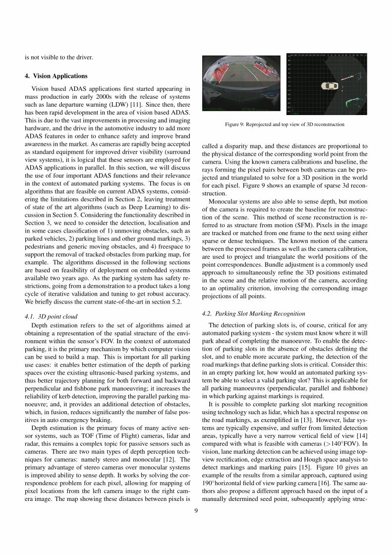
Figure 9: Reprojected and top view of 3D reconstruction
called a disparity map, and these distances are proportional tothe physical distance of the corresponding world point from thecamera. Using the known camera calibrations and baseline, therays forming the pixel pairs between both cameras can be pro-jected and triangulated to solve for a 3D position in the worldfor each pixel. Figure 9 shows an example of sparse 3d recon-struction.
Monocular systems are also able to sense depth, but motionof the camera is required to create the baseline for reconstruc-tion of the scene. This method of scene reconstruction is re-ferred to as structure from motion (SFM). Pixels in the imageare tracked or matched from one frame to the next using eithersparse or dense techniques. The known motion of the camerabetween the processed frames as well as the camera calibration,are used to project and triangulate the world positions of thepoint correspondences. Bundle adjustment is a commonly usedapproach to simultaneously refine the 3D positions estimatedin the scene and the relative motion of the camera, accordingto an optimality criterion, involving the corresponding imageprojections of all points.
4.2. Parking Slot Marking Recognition
The detection of parking slots is, of course, critical for anyautomated parking system - the system must know where it willpark ahead of completing the manoeuvre. To enable the detec-tion of parking slots in the absence of obstacles defining theslot, and to enable more accurate parking, the detection of theroad markings that define parking slots is critical. Consider this:in an empty parking lot, how would an automated parking sys-tem be able to select a valid parking slot? This is applicable forall parking manoeuvres (perpendicular, parallel and fishbone)in which parking against markings is required.
It is possible to complete parking slot marking recognitionusing technology such as lidar, which has a spectral response onthe road markings, as exemplified in [13]. However, lidar sys-tems are typically expensive, and suffer from limited detectionareas, typically have a very narrow vertical field of view [14]compared with what is feasible with cameras (>140◦FOV). Invision, lane marking detection can be achieved using image top-view rectification, edge extraction and Hough space analysis todetect markings and marking pairs [15]. Figure 10 gives anexample of the results from a similar approach, captured using190◦horizontal field of view parking camera [16]. The same au-thors also propose a different approach based on the input of amanually determined seed point, subsequently applying struc-
9

Figure 10: Example of parking slot marking recognition
tural analysis techniques to extract the parking slot [17]. Al-ternatively, a pre-trained model-based method based on HOG(Histogram of Oriented Gradients) and LBP (Local Binary Pat-terns) features, with linear SVM (Support Vector Machine) ap-plied to construct the classification models is proposed in [18].
Regardless of the specific approach taken, what is clear is thatthe detection of marking slots is critical for a complete auto-mated parking system, and that the only reasonably valid tech-nology to complete this is parking cameras with a wide field ofview.
4.3. Vehicle and Pedestrian Detection/Tracking
Vehicle detection and tracking is often done in the contextof front camera detection [19] for applications like auto emer-gency braking or in traffic surveillance applications [20]. How-ever, parking manoeuvres are often done in the presence ofother vehicles, either parked or moving, and as such, the de-tection and tracking of vehicles is important for the automa-tion of such manoeuvres [21]. Perhaps of higher importancein parking manoeuvres is for the system to reliably be able toboth detect and classify pedestrians [22], such that the vehiclecan take appropriate action, e.g. auto emergency braking in thepresence of pedestrians that are at potential risk [22] (Figure11). Typically, both the problem of vehicle detection and thatof pedestrian detection are solved using some flavour of clas-sification. No other sensor can as readily and reliably classifydetection based on object type, compared to vision systems.
Object classification generally falls under supervised classi-fication group of machine learning algorithms. This is basedon the knowledge that a human can select sample thumbnailsin multiple images that are representative of a specific classof object. With the use of feature extraction methods such ashistogram of oriented gradients (HOG), local binary patterns(LBP), and wavelets applied to the human classified sample im-ages, a predictor model is built using machine learning in orderto classify objects. Many vision based ADAS functions usemachine learning approaches for classification. As already dis-cussed, classification is extensively used in pedestrian and vehi-cle detection, but also in areas such as face detection and trafficsign recognition (TSR). The quality of the final algorithm ishighly dependent on the amount and quality of the sample dataused for learning the classifiers, as well as the overall quality ofthe classification technique and the appropriateness of the fea-ture selection method for the target application. Typical clas-sifiers include SVMs, random forest and convolutional neuralnetworks (CNN). Recently there has been a shift in this trendvia deep learning methods wherein the features are automati-cally learned.
Figure 11: Pedestrian classification and tracking using a parking camera
4.4. Freespace
Freespace is a feature used by most environmental sensingmaps. Freespace is the area around the vehicle within the sen-sor’s field of view that is not occupied by objects, and is oftenclassed as an occupancy grid map problem [22], and is typ-ically detected by segmenting the ground surface from otherobjects [23], [24]. In an occupancy-grid map approach, thefreespace information is integrated and stored over time. Inthe case of a vector-based map representation, each object’s ex-istence probability is updated based on the freespace measure-ments. Freespace is used to erase dynamic and static obstaclesin the environmental sensing map which are not actively beingmeasured or updated. That means a good freespace model willerase dynamic obstacles from previous positions very quicklywithout erasing valid static information. Freespace should alsoerase previously detected static objects that have moved sincethe last valid measurement, detections that have position errorin the map due to odometry update errors and false positives.Figure 12 shows an example of image segmentation (e.g.) basedfreespace from a parking camera. Furthermore freespace sup-ports a collision free trajectory search and planning especiallyin accumulated freespace grid maps.
Unlike other sensor types, vision systems can provide dif-ferent, independent methods of estimating vehicle freespace.For example, an alternate method to determine camera-basedfreespace is to make use of 3D point cloud and its correspond-ing obstacle information. However, it also reconstructs featureson the road surface around the vehicle. The features that arereconstructed that are associated with the ground can be usedto provide valuable freespace information. If there is a fea-ture reconstructed that is associated with the ground, then it isa reasonable assumption that the area between that point andthe sensor (camera) is not obstructed by an object, and it canbe used to define a freespace region around the host vehicle.As these methods are independent and complementary, it canalso be beneficial to fuse these techniques (with themselves, andwith freespace provided by other sensors, such as ultrasonics)in order to increase the accuracy and robustness of the freespacemeasurement.
4.5. Other vision functions
There are several other areas that computer vision techniquescan support in the automated parking space. Visual Odom-etry is a task that is strongly linked to the depth estimation
10

Figure 12: (a) shows the road segmented from the rest of the scene use image-based segmentation, and (b) shows radial cell based freespace definition basedon the road segmentation from (a)
described in Section 4.1, via visual SLAM/bundle adjustmenttechniques [25], although there are other methods for visualodometry [26]. While vehicle odometry is available on vehi-cle networks (CAN/FlexRay), relying solely on these signalsis inaccurate due to delays over the network, signal limitationsand inaccuracies (e.g. relying on accelerometers), and limiteddegrees of freedom (typically only velocity and heading). In au-tomated parking, the quality of the odometry is critical to usercomfort and parking accuracy - as the odometry is improved,parking can be completed in fewer individual manoeuvres, andthe final positions is closer to the target location.
Crossing traffic alert algorithms are designed to detect trafficthat is potentially a threat to the host vehicle in certain criticalsituations at junctions, such as at a T-junction (particularly ifthere is limited visibility) [27]. The need for a crossing traf-fic alert function on vehicles is obvious: according to the roadsafety website of the European Commission [28], 40 to 60 % ofthe total number of accidents occur at junctions. However, inthe specific context of automated parking, crossing traffic de-tection is important to restrict the motion of the host vehicle, inparticular when exiting a parking space, as shown in first partof Figure 13. Second picture of Figure 13 shows an example ofan algorithms for the detection of crossing vehicles, based onoptical flow with host odometry compensation.
Other than the detection of parking slot markings discussedearlier, it is also important to be able to detect other road mark-ings, such as arrows and disabled parking markings [28], androad signs [29], which allows the autonomously parking vehi-cle to follow the rules defined in the parking area.
4.6. A note on accuracy
Finally for this section, we discuss briefly the accuracy re-quired from computer vision to support the parking functions.There are two types of accuracy of the algorithms for a parkingsystem namely detection accuracy and localisation accuracy.Computer vision benchmarks typically focus on the former butfrom the parking perspective, localisation is very important aswell. Of course, accuracy requirements are driven by the de-sired functionality; conversely, the error rate of algorithms candefine the feasibility of specific functions. For example, for cur-rent generation parking systems, in which the system parks inplaces where typically a driver could normally park, accuracyof depth of detections in the region of 10 to 15cm is adequate,as long as the standard deviation is low ( 5cm). However, in
Figure 13: Example of a crossing traffic situation on parking space exit, and (b)shows a screenshot of an algorithm for the detection of crossing traffic
the future, we may envisage automated cars parking in placesdedicated to the storage of fully autonomous vehicles. In sucha case, there would be a strong desire for the vehicles to parkas closely as possible, thus maximising the vehicles parked perarea, and as such detection accuracies of 5cm or lower wouldbe strongly desirable.
If we discuss emergency braking in a parking scenario, thebraking must only happen at the point that collision would oth-erwise be unavoidable, perhaps when the obstacle is only 20cmfrom the vehicle. The reason is quite straightforward: in a park-ing scenario manoeuvre is slow, and often there are many obsta-cles, thus allowing a larger braking distance will lead to annoy-ing and confusing vehicle behaviour for the driver. Thereforedepth accuracies of, for example, pedestrian detection should bein the region of 10cm to allow for vehicle motion and systemlatencies. Of course, the lower the braking distance the better,as the system can brake later while maintaining safety. Park slotmarking detection requirements are stringent as the car has tobe perfectly parked, as shown in Figure 6. In such cases, locali-sation errors of 30cm in direction of the camera optical axis and10cm in direction laterally of the camera position are desirable.
These are discussion points. The actual accuracy require-ment that needs to be achieved from any given algorithm mustbe decided upon by taking into account the exact end user func-tions of the parking system, the limitations in computationalpower of an embedded system, and the algorithmic feasibilityof the function. Additionally, while the requirements for ac-curacy can be very high (recalling that in computer vision wenatively detect angles, and not depth), within a fusion systemthe accuracies of other sensors, such as ultrasonics, can be usedto support the camera based detection in a complementary man-ner.
5. The Automated Parking System
5.1. Automated Parking System ConsiderationsAs discussed in section 2, 3 & 4 as well as illustrated in Fig-
ure 14 there are many factors that influence the specificationof a vision or partly vision (fusion) based automated parkingsystem. Few parts of the system can be considered in isola-tion due to the the majority of choices having a system wideimpact. A simple example is the selection of camera pixelresolution which can impact the potential use cases achiev-able by the system through both hardware and software; cam-era resolution impacts ISP selection, SerDes selection, memory
11

Application Stack
Embedded Computer Vision Algorithms
ECU
Memory System Interconnect (I2C/GPIO) SPI/PCI
DDR
Flash
SerDes
CAMERAS - Optics - Sensors - ISP
Use Cases: Motion Planning
Perpendicular Parking Ambiguous Parking
Parallel Parking Fishbone Parking
Parking Slot Marking Detection
Freespace
CV Supporting Functions
Structure from motion
Pedestrian/Vehicle detection
ECU IF
Video i/p: LVDS/ETH
Video o/p: LVDS/ETH/HDMI
Veh IF: CAN/FR/ETH
Debug IF: JTAG/UART/USB/ETH
SOC
Vision HWA
DSP GPUSIMD
Engine
RAM
COM IF
Mem IF
Codec HWA
ISPVID IF
ROMARM
FPGA
SWHW
Sensor Fusion
Figure 14: Application Stack for full Automated Parking system using cameras.
bandwidth requirements, memory requirements, computationalrequirements of computer vision, accuracy and range perfor-mance of system, low light performance and display require-ments. Therefore some limitations in terms of hardware, usecases and computer vision algorithms need to be understoodand defined as illustrated in Figure 3.
From a hardware perspective the main variables, bearing inmind that thermal, power, cost are within tolerance, is the se-lection of the camera imager and ECU processing SOC. Typicalautomotive imagers for surround view applications are movingaway from 1MP to 2-4MP resolutions. The challenge in in-creasing resolution is do so while maintaining or preferably im-proving low light sensitivity. This is critical for the availabilityand thus usability of camera based automated parking system.The extra pixel resolution improves the accuracy and rangeof the system allowing for increased parking use cases, morerobust parking performance and increased speed availability.Once an image is formed the key is to process as many com-puter vision functions in parallel at as a high a frame rate andhigh a resolution as possible. This is where the SOC selectionis critical. There are always trade-offs to reduce system load in-cluding the deployment of intelligent state machines to ensureonly critical computer vision algorithms are running, downscal-ing and skipping of processed images to reduce loading. Thesetrade-offs are becoming less restrictive as pixel level process-ing, that is generally 60-70% of the loading of any computervision algorithm, traditionally performed on hardware vectorprocessing engines or DSPs are being superseded by specificcomputer vision hardware accelerators. These computer visionaccelerators for processes such as dense optical flow, stereo dis-parity and convolutions are capable of much higher pixel pro-cessing throughput at lower power consumption at the expenseof flexibility.
The use cases required to be covered by the system also playsa significant role in system specification. The automated park-ing use cases to be covered in turn define the requirements forthe detection capability, accuracy, coverage, operating range,operating speed and system availability amongst others. Thisimpacts the sensor and SOC selection but most significantly itdefines the required performance from the computer vision al-gorithms in order to be able to achieve the functionality. For ex-ample automated perpendicular parking between lines requiresmany computer vision algorithms to be working in parallel,with the required accuracy and robustness to achieve a reliableand useful function. Firstly a line marking detection algorithmis required to be performing up to a speed and detection rangethat is practical for automated parking slot searching. In par-allel an algorithm such as structure from motion is required toensure that there is no object (parking lock, cone, rubbish binetc.) in the slot while also measuring the end position of the slotwhich might be in the form of a Kerb. Pedestrian detection isalso a nice addition to reduce but not remove the burden of su-pervision on the user during the parking manoeuvre (Level 2).These computer vision functions require support from onlinecalibration algorithms and soiling detection functions to bothoperate and understand when they are not available so the sys-tem and thus user can be informed. The camera informationis typically fused over time as well as with other range sensorinformation such as ultrasonic or radar data to improve systemrobustness, accuracy and availability. However, there are somedetections required that only cameras can achieve such as clas-sification. The more functions that a camera can fulfil reducessystem costs as surround view cameras are becoming a stan-dard sensor, therefore the more functions that they can achievethe less supporting sensors are required.
5.2. A glimpse into next generation
Computer vision has witnessed tremendous progress recentlywith deep learning, specifically convolutional neural networks(CNN). CNNs has enabled a large increase in accuracy of ob-ject detection leading to better perception for automated driving[30]. It has also enabled dense pixel classification via semanticsegmentation which was not feasible before [31]. Additionallythere is a strong trend of CNN achieving state-of-the-art resultsfor geometric vision algorithms like optical flow [32], structurefrom motion [33] and re-localisation [34]. The progress in CNNhas also led to the hardware manufacturers to include a customHW IP to provide a high throughput of over 10 Tera operationsper second (TOPS). Additionally the next generation hardwarewill have dense optical flow and stereo HW accelerators to en-able generic detection of moving and static objects.
From a use case perspective, the next step for parking sys-tems is to make them truly autonomous, which will allow adriver to leave a car to locate and park in an unmapped environ-ment without any driver input. In addition to this, the vehicleshould be able to exit the parking slot and return to the driversafely. Cameras can play a very important role in the future ofautomated parking systems, providing important informationabout the vehicle’s surroundings. This includes information
12

Figure 15: Example of a Park4U Home Use Case where vision based systemsuses landmarks to localise the car to an already stored trajectory to navigateautonomous into the home parking slot
like object and freespace data, parking slot marking detection,pedestrian detection for fusion with other sensor technologies.
As discussed in this article current automated parking sys-tems take control of the vehicle after recognition and selectionof the parking slot by the user. The state of the system duringslot search is essentially passive. The trend and challenge forthe future is the automation of slot search itself in order to al-low for complete vehicle parking automation including search,selection & park all in a robust, repeatable and safe way. Theseautomated parking scenarios can be classified as follows: 1)Automated Parking in a known area and 2) Automated Parkingin an unknown area. Automated Parking in known areas typi-cally involves the driver “training” the automated parking sys-tem with a parking trajectory (see Figure 15). During this train-ing the sensors locate the landmarks in the scene and record thedesired trajectory driven by the driver against these landmarks.The automated parking system can recognize the scene when itreturns and uses the trained information to automatically local-ize the vehicle to the stored trajectory allowing for automatedparking. A variant of such functionality is for example “Park4Uhome ”.
Parking using a recorded trajectory poses many significantobstacles. Objects present during the training sequence maynot exist during replay of the manoeuvre, for example cars, rub-bish bins etc and this means that these obstacles are suitable forlocalisation. Even worse, objects can move very slightly in thescene between training and replay. If the system cannot identifythat these objects have moved and uses them for localisation, itcan result in poor trajectory replay. Objects can be moved to
obstruct the trajectory during replay and this can simply resultin an abort of the manoeuvre while more intelligent avoidancetechniques to rejoin trajectory around the obstacle require notonly extended sensor range but knowledge of drivable area andalso potentially information about the private and public roaddivide. The complexity of traversing a trained trajectory canbe increased by differences between the training and replay notonly in the structure of the scene itself but also the weatherand lighting conditions. These condition changes can result invastly different views of the same scene, particularly from a vi-sual sensor, making identification of and localisation within the“home zone” very difficult.
Automated Parking in unknown areas requires the automa-tion of the search, selection and parking of the vehicle withoutthe car having any prior stored trajectory. In terms of complex-ity this is a significant step over automated parking in knownareas. Automated Parking in unknown areas was introduced byValeo at the Frankfurt motor show via the name Valeo ValetPark4U [35].
The challenges to realize the jump to new automation levelsis to extend vision based automated parking systems in terms ofego vehicle localisation (SLAM) and allow for accurate identi-fication of stored home area. To reach the highest levels ofautomation for automatic parking systems it is clear that a com-bination of sensor technologies (Camera, Ultrasonic, Radar orLidar) is required to reach the maximum of accuracy, reliabilityin ego localisation, detection and prediction of the environment.
6. Conclusion
Automated driving is a rapidly growing area of technologyand many high end cars have begun to ship with self-parkingfeatures. This has led to improved sensors and massive increasein computational power which can produce more robust andaccurate systems. Government regulating bodies like EuroN-CAP and NHTSA are introducing progressive legislation to-wards mandating safety systems, in spite of challenges in liabil-ity, and are starting to legislate to allow autonomous vehicles onthe public road network. Camera sensors will continue to playan important role because of its low cost and the rich seman-tics it captures relative to other sensors. In this paper, we havefocussed on the benefits of camera sensors and how it enablesparking use cases. We have discussed the system implementa-tion of an automated parking system with four fisheye cameraswhich provides 360 ◦view surrounding the vehicle. We coveredvarious aspects of the system in detail including embedded sys-tem components, parking use cases which need to be handledand the vision algorithms which solve these use cases. As thefocus on computer vision aspects, we have omitted the detailsof sensor fusion, trajectory control and motion planning.
Acknowledgement
All screenshots of computer vision algorithms are from prod-ucts that have been developed by Valeo Vision Systems. Thanksto B Ravi Kiran (INRIA France), Prashanth Viswanath (TI),
13

Michal Uricar (Valeo), Ian Clancy (Valeo) and Margaret Toohey(Valeo) for reviewing the paper and providing feedback.
References
[1] Autonomous driving levels 0 to 5: Understanding the differences,http://www.techrepublic.com/article/autonomous-driving-levels-0-to-5-understanding-the-differences (2016 (accessed March 26, 2017)).
[2] J. Horgan, C. Hughes, J. McDonald, S. Yogamani, Vision-based driver as-sistance systems: Survey, taxonomy and advances, in: Intelligent Trans-portation Systems (ITSC), 2015 IEEE 18th International Conference on,IEEE, 2015, pp. 2032–2039.
[3] S. Mahmud, G. Khan, M. Rahman, H. Zafar, et al., A survey of intelligentcar parking system, Journal of applied research and technology 11 (5)(2013) 714–726.
[4] C. Wang, H. Zhang, M. Yang, X. Wang, L. Ye, C. Guo, Automatic park-ing based on a bird’s eye view vision system, Advances in MechanicalEngineering 6 (2014) 847406.
[5] J. Xu, G. Chen, M. Xie, Vision-guided automatic parking for smart car,in: Intelligent Vehicles Symposium, 2000. IV 2000. Proceedings of theIEEE, IEEE, 2000, pp. 725–730.
[6] J. Farrell, F. Xiao, S. Kavusi, Resolution and light sensitivity tradeoff withpixel size, in: Electronic Imaging 2006, International Society for Opticsand Photonics, 2006, pp. 60690N–60690N.
[7] G. D. Boreman, Modulation transfer function in optical and electro-optical systems, Vol. 21, SPIE press Bellingham, WA, 2001.
[8] C. Hughes, M. Glavin, E. Jones, P. Denny, Wide-angle camera technologyfor automotive applications: a review, IET Intelligent Transport Systems3 (1) (2009) 19–31.
[9] D. K. Mandal, J. Sankaran, A. Gupta, K. Castille, S. Gondkar, S. Kamath,P. Sundar, A. Phipps, An embedded vision engine (eve) for automotivevision processing, in: Circuits and Systems (ISCAS), 2014 IEEE Interna-tional Symposium on, IEEE, 2014, pp. 49–52.
[10] S. O.-R. A. V. S. Committee, et al., Taxonomy and definitions for termsrelated to on-road motor vehicle automated driving systems (2014).
[11] S. Sivaraman, M. M. Trivedi, Integrated lane and vehicle detection, lo-calization, and tracking: A synergistic approach, IEEE Transactions onIntelligent Transportation Systems 14 (2) (2013) 906–917.
[12] R. Hartley, A. Zisserman, Multiple view geometry in computer vision,Cambridge university press, 2003.
[13] A. Hata, D. Wolf, Road marking detection using lidar reflective intensitydata and its application to vehicle localization, in: Intelligent Transporta-tion Systems (ITSC), 2014 IEEE 17th International Conference on, IEEE,2014, pp. 584–589.
[14] Velodyne hdl-64e datasheet, http://velodynelidar.com/lidar/products/brochure/HDL-64E%20Data%20Sheet.pdf (2015 (accessed January 29, 2017)).
[15] H. G. Jung, D. S. Kim, P. J. Yoon, J. Kim, Parking slot markings recogni-tion for automatic parking assist system, in: Intelligent Vehicles Sympo-sium, 2006 IEEE, IEEE, 2006, pp. 106–113.
[16] Y.-C. Liu, K.-Y. Lin, Y.-S. Chen, Bird’s-eye view vision system for vehi-cle surrounding monitoring, in: International Workshop on Robot Vision,Springer, 2008, pp. 207–218.
[17] H. G. Jung, D. S. Kim, P. J. Yoon, J. Kim, Structure analysis basedparking slot marking recognition for semi-automatic parking system, in:Joint IAPR International Workshops on Statistical Techniques in Pat-tern Recognition (SPR) and Structural and Syntactic Pattern Recognition(SSPR), Springer, 2006, pp. 384–393.
[18] B. Su, S. Lu, A system for parking lot marking detection., in: PCM, 2014,pp. 268–273.
[19] S. Sivaraman, M. M. Trivedi, Looking at vehicles on the road: A surveyof vision-based vehicle detection, tracking, and behavior analysis, IEEETransactions on Intelligent Transportation Systems 14 (4) (2013) 1773–1795.
[20] N. Buch, S. A. Velastin, J. Orwell, A review of computer vision tech-niques for the analysis of urban traffic, IEEE Transactions on IntelligentTransportation Systems 12 (3) (2011) 920–939.
[21] A. Broggi, E. Cardarelli, S. Cattani, P. Medici, M. Sabbatelli, Vehicledetection for autonomous parking using a soft-cascade adaboost classifier,
in: Intelligent Vehicles Symposium Proceedings, 2014 IEEE, IEEE, 2014,pp. 912–917.
[22] P. Dollar, C. Wojek, B. Schiele, P. Perona, Pedestrian detection: An eval-uation of the state of the art, IEEE transactions on pattern analysis andmachine intelligence 34 (4) (2012) 743–761.
[23] H. Badino, U. Franke, R. Mester, Free space computation using stochasticoccupancy grids and dynamic programming, in: Workshop on DynamicalVision, ICCV, Rio de Janeiro, Brazil, Vol. 20, Citeseer, 2007.
[24] P. Cerri, P. Grisleri, Free space detection on highways using time correla-tion between stabilized sub-pixel precision ipm images, in: Robotics andAutomation, 2005. ICRA 2005. Proceedings of the 2005 IEEE Interna-tional Conference on, IEEE, 2005, pp. 2223–2228.
[25] J. Fuentes-Pacheco, J. Ruiz-Ascencio, J. M. Rendon-Mancha, Visual si-multaneous localization and mapping: a survey, Artificial Intelligence Re-view 43 (1) (2015) 55–81.
[26] D. Scaramuzza, R. Siegwart, Appearance-guided monocular omnidirec-tional visual odometry for outdoor ground vehicles, IEEE transactions onrobotics 24 (5) (2008) 1015–1026.
[27] D. Savage, C. Hughes, J. Horgan, S. Finn, Crossing traffic alert and ob-stacle detection with the valeo 360vue® camera system, in: ERTICO 9thITS European Congress, 2013.
[28] S. Vacek, C. Schimmel, R. Dillmann, Road-marking analysis for au-tonomous vehicle guidance., in: EMCR, 2007.
[29] A. Mogelmose, M. M. Trivedi, T. B. Moeslund, Vision-based traffic signdetection and analysis for intelligent driver assistance systems: Perspec-tives and survey, IEEE Transactions on Intelligent Transportation Systems13 (4) (2012) 1484–1497.
[30] A. Geiger, P. Lenz, C. Stiller, R. Urtasun, Vision meets robotics: The kittidataset, The International Journal of Robotics Research 32 (11) (2013)1231–1237.
[31] M. Cordts, M. Omran, S. Ramos, T. Rehfeld, M. Enzweiler, R. Benen-son, U. Franke, S. Roth, B. Schiele, The cityscapes dataset for semanticurban scene understanding, in: Proceedings of the IEEE Conference onComputer Vision and Pattern Recognition, 2016, pp. 3213–3223.
[32] E. Ilg, N. Mayer, T. Saikia, M. Keuper, A. Dosovitskiy, T. Brox, Flownet2.0: Evolution of optical flow estimation with deep networks, arXivpreprint arXiv:1612.01925.
[33] B. Ummenhofer, H. Zhou, J. Uhrig, N. Mayer, E. Ilg, A. Dosovitskiy,T. Brox, Demon: Depth and motion network for learning monocularstereo, arXiv preprint arXiv:1612.02401.
[34] T. Naseer, G. L. Oliveira, T. Brox, W. Burgard, Semantics-aware visuallocalization under challenging perceptual conditions, in: IEEE Interna-tional Conference on Robotics and Automation, IEEE.
[35] Valet park4u®, the automated parking system, http://newatlas.com/valeo-park4u-automated-parking-system/29315/(2013 (accessed January 29, 2017)).
14