Computer vision class, fast-forward -...
59
Transcript of Computer vision class, fast-forward -...

Today

Reading
• Related to today’s lecture: – Adelson article on pyramid representations,
posted on web site.– Farid paper posted on web site.
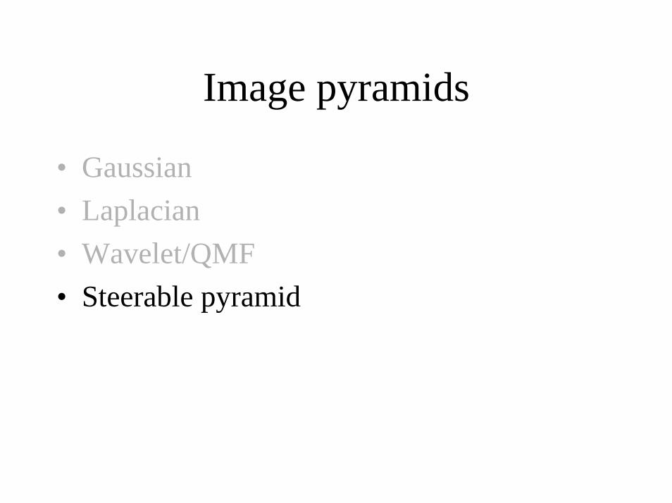
Image pyramids
• Gaussian• Laplacian• Wavelet/QMF• Steerable pyramid

Steerable pyramids
• Good:– Oriented subbands– Non-aliased subbands– Steerable filters
• Bad:– Overcomplete– Have one high frequency residual subband, required in
order to form a circular region of analysis in frequency from a square region of support in frequency.
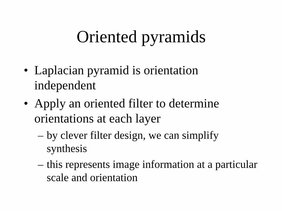
Oriented pyramids
• Laplacian pyramid is orientation independent
• Apply an oriented filter to determine orientations at each layer– by clever filter design, we can simplify
synthesis– this represents image information at a particular
scale and orientation


Simoncelli and Freeman, ICIP 1995http://www.cns.nyu.edu/ftp/eero/simoncelli95b.pdf
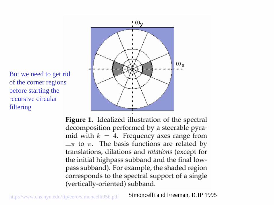
But we need to get rid of the corner regions before starting the recursive circular filtering
Simoncelli and Freeman, ICIP 1995http://www.cns.nyu.edu/ftp/eero/simoncelli95b.pdf
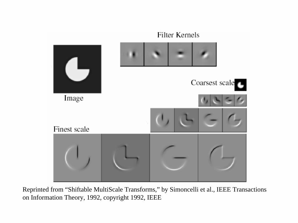
Reprinted from “Shiftable MultiScale Transforms,” by Simoncelli et al., IEEE Transactionson Information Theory, 1992, copyright 1992, IEEE

• Summary of pyramid representations
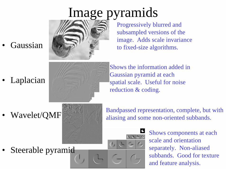
Image pyramids
Shows the information added in Gaussian pyramid at each spatial scale. Useful for noise reduction & coding.
Progressively blurred and subsampled versions of the image. Adds scale invariance to fixed-size algorithms.
Shows components at each scale and orientation separately. Non-aliased subbands. Good for texture and feature analysis.
Bandpassed representation, complete, but with aliasing and some non-oriented subbands.
• Gaussian
• Laplacian
• Wavelet/QMF
• Steerable pyramid
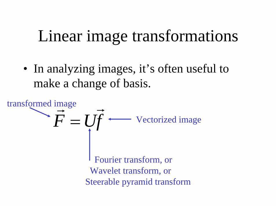
Linear image transformations
• In analyzing images, it’s often useful to make a change of basis.
Fourier transform, orWavelet transform, or
Steerable pyramid transform
fUFrr
=transformed image
Vectorized image
Schematic pictures of each matrix transform
• Shown for 1-d images• The matrices for 2-d images are the same
idea, but more complicated, to account for vertical, as well as horizontal, neighbor relationships.

Fourier transform
= *
Fourier transform
Fourier bases are global: each transform coefficient depends on all pixel locations.
pixel domain image
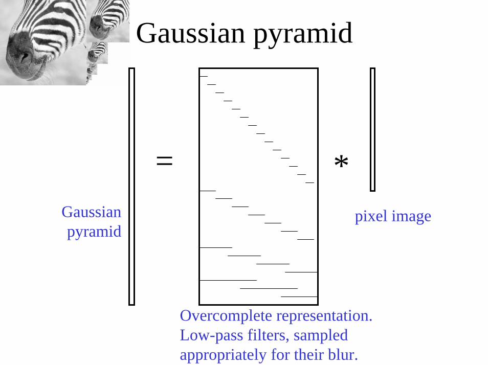
Gaussian pyramid
= *pixel image
Overcomplete representation. Low-pass filters, sampled appropriately for their blur.
Gaussian pyramid
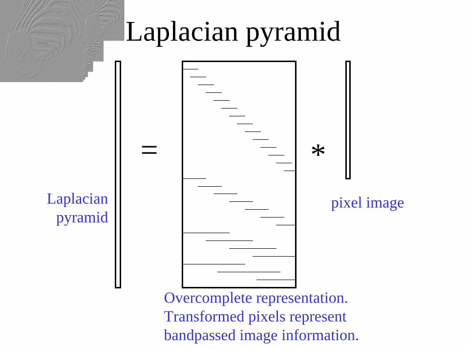
Laplacian pyramid
= *Laplacian
pyramidpixel image
Overcomplete representation. Transformed pixels represent bandpassed image information.
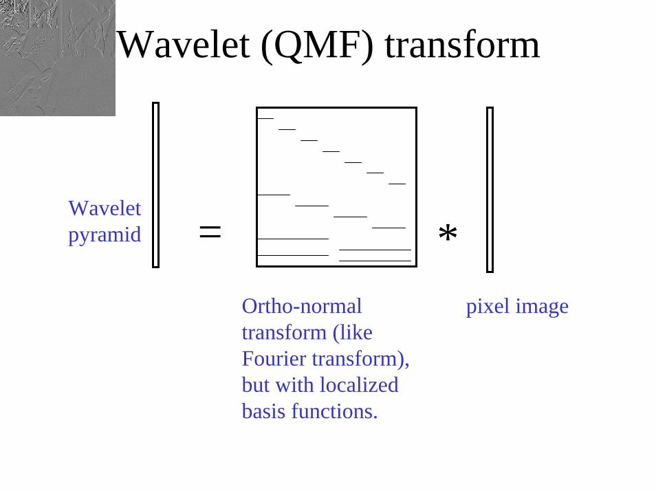
Wavelet (QMF) transform
Wavelet pyramid = *
Ortho-normal transform (like Fourier transform), but with localized basis functions.
pixel image
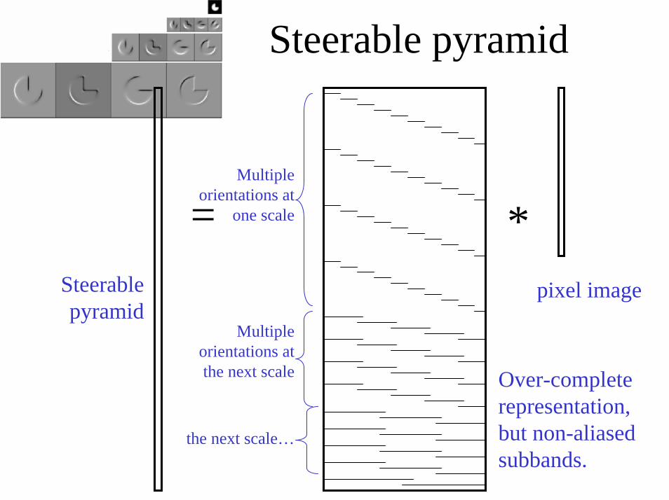
= *Steerablepyramid
pixel image
Over-complete representation, but non-aliased subbands.
Multiple orientations at
one scale
Multiple orientations at the next scale
the next scale…
Steerable pyramid

Matlab resources for pyramids (with tutorial)http://www.cns.nyu.edu/~eero/software.html

Why use these representations?
• Handle real-world size variations with a constant-size vision algorithm.
• Remove noise• Analyze texture• Recognize objects• Label image features
An application of image pyramids:noise removal

Image statistics (or, mathematically, how can you tell image from noise?)
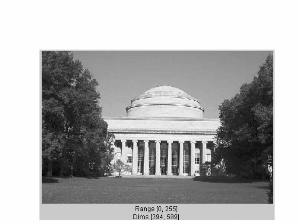

Pixel representation image histogram
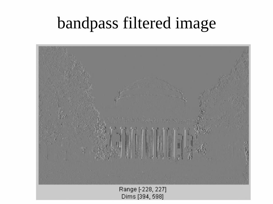
bandpass filtered image
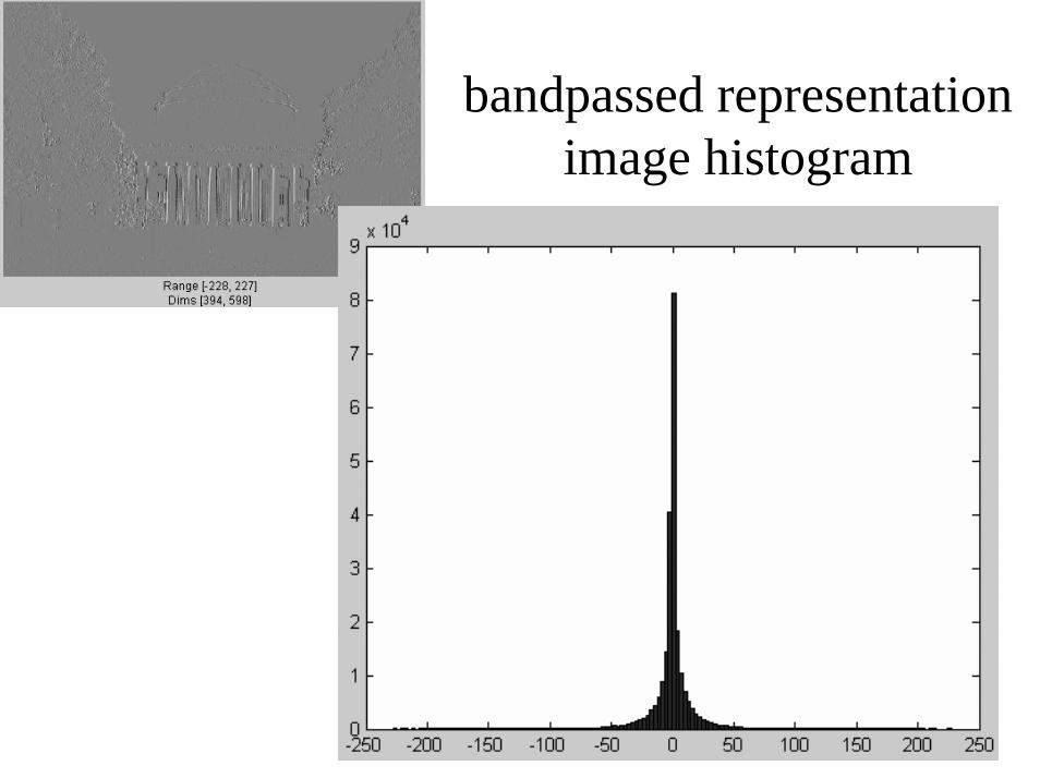
bandpassed representation image histogram
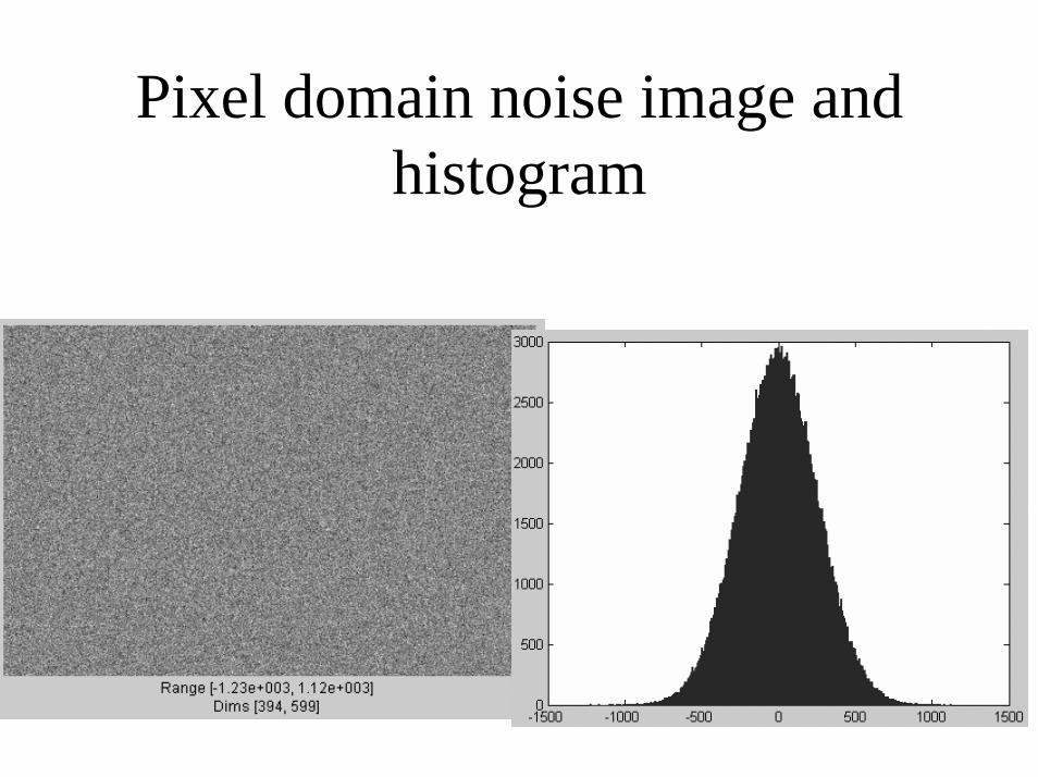
Pixel domain noise image and histogram
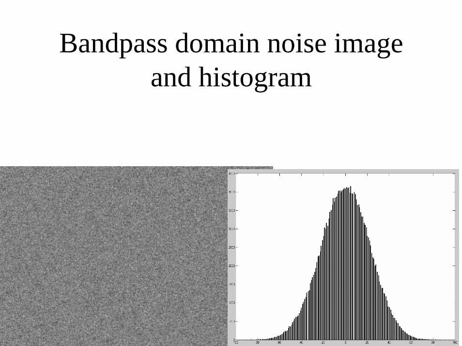
Bandpass domain noise image and histogram

Noise-corrupted full-freq and bandpass images

Bayes theorem
P(x, y) = P(x|y) P(y)soP(x|y) P(y) = P(y|x) P(x)
P(x, y) = P(x|y) P(y)soP(x|y) P(y) = P(y|x) P(x)
P(x, y) = P(x|y) P(y)
andP(x|y) = P(y|x) P(x) / P(y)
The parameters you want to estimate
What you observe Prior probability
Likelihood function
Constant w.r.t. parameters x.
P(x)
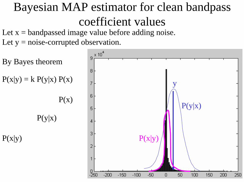
Bayesian MAP estimator for clean bandpasscoefficient values
Let x = bandpassed image value before adding noise.Let y = noise-corrupted observation.
By Bayes theorem
P(x|y) = k P(y|x) P(x)
P(y|x)
y
P(y|x)
P(x|y)P(x|y)

P(x)
Let x = bandpassed image value before adding noise.Let y = noise-corrupted observation.
By Bayes theorem
P(x|y) = k P(y|x) P(x)
P(y|x)
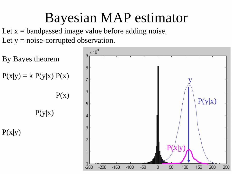
Bayesian MAP estimator
y
P(y|x)
P(x|y)P(x|y)
P(x)
Let x = bandpassed image value before adding noise.Let y = noise-corrupted observation.
By Bayes theorem
P(x|y) = k P(y|x) P(x)
P(y|x)
Bayesian MAP estimator
y
P(y|x)
P(x|y)
P(x|y)
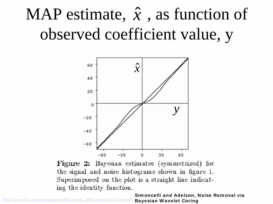
MAP estimate, , as function of observed coefficient value, y
x̂
y
x̂
http://www-bcs.mit.edu/people/adelson/pub_pdfs/simoncelli_noise.pdfSimoncelli and Adelson, Noise Removal via Bayesian Wavelet Coring
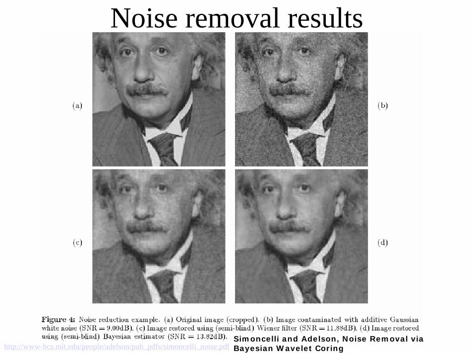
Noise removal results
http://www-bcs.mit.edu/people/adelson/pub_pdfs/simoncelli_noise.pdfSimoncelli and Adelson, Noise Removal via Bayesian Wavelet Coring
Insert hany farid slides
Non-linear filtering example

Median filterReplace each pixel by the median over N pixels (5 pixels, for these examples). Generalizes to “rank order” filters.
Spike noise is removed
In: Out:
5-pixel neighborhood
Monotonic edges remain unchanged
Out:In:

Degraded image
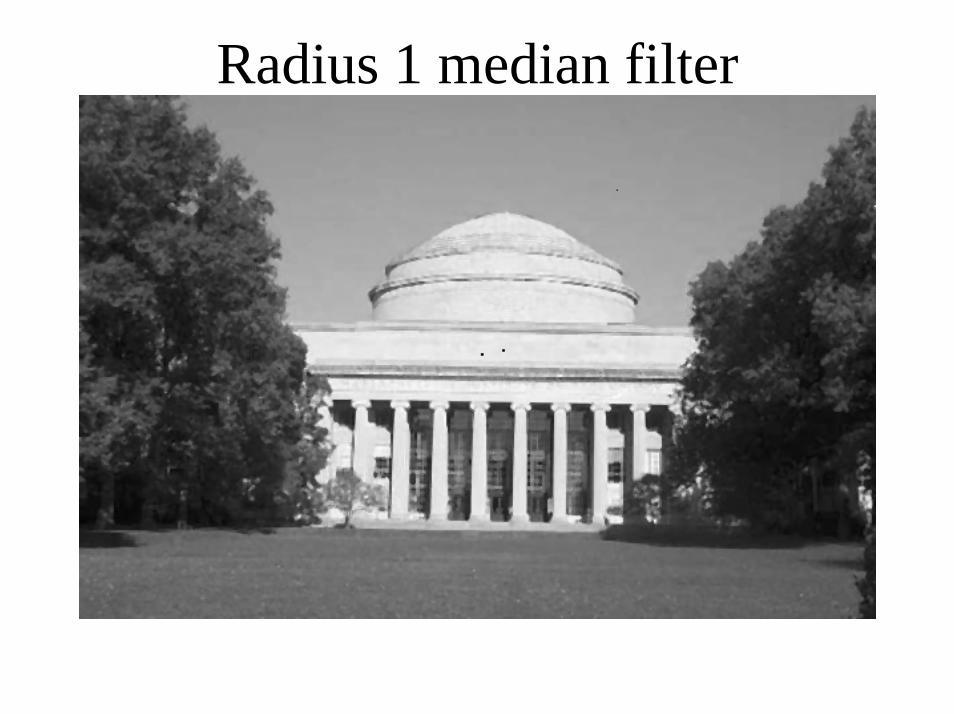
Radius 1 median filter
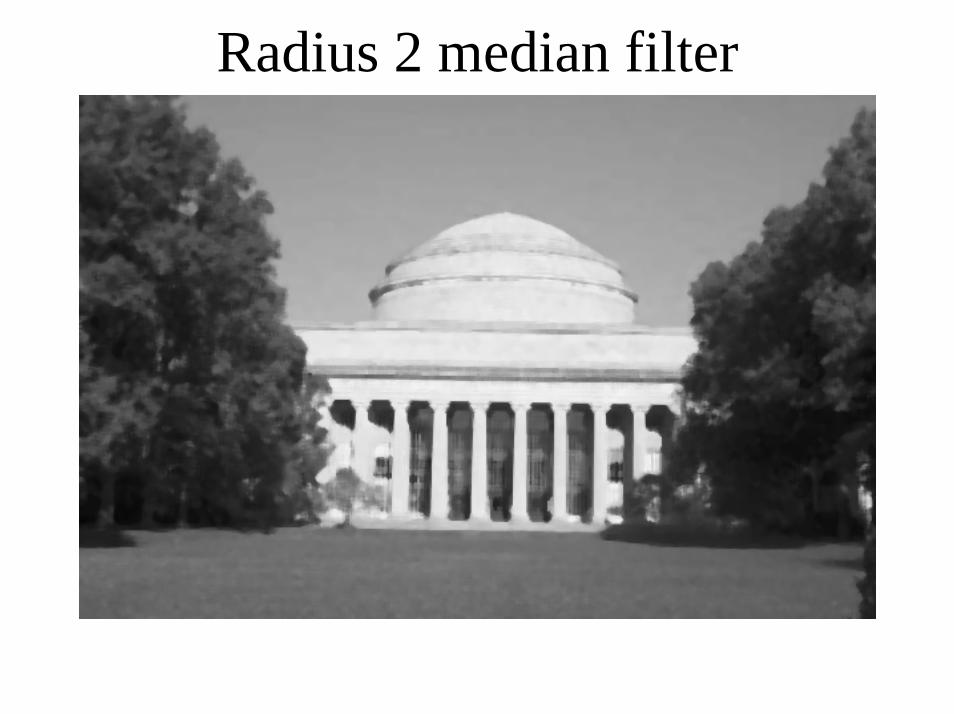
Radius 2 median filter

CCD color sampling
Color sensing, 3 approaches
• Scan 3 times (temporal multiplexing)• Use 3 detectors (3-ccd camera, and color
film)• Use offset color samples (spatial
multiplexing)

Typical errors in temporal multiplexing approach
• Color offset fringes

Typical errors in spatial multiplexing approach.
• Color fringes.

CCD color filter pattern
detector

The cause of color moire
detector
Fine black and white detail in imagemis-interpreted as color information.
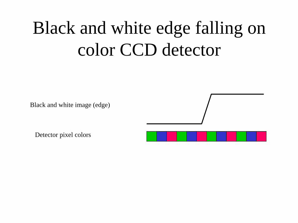
Black and white edge falling on color CCD detector
Black and white image (edge)
Detector pixel colors
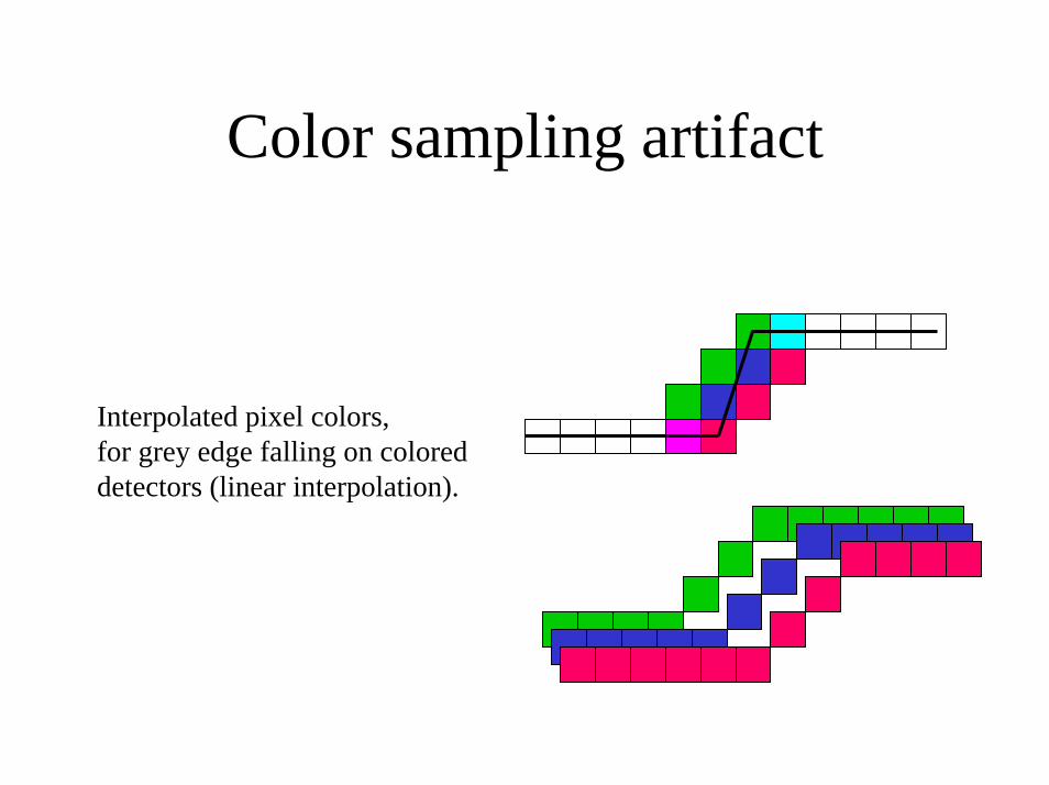
Color sampling artifact
Interpolated pixel colors, for grey edge falling on coloreddetectors (linear interpolation).
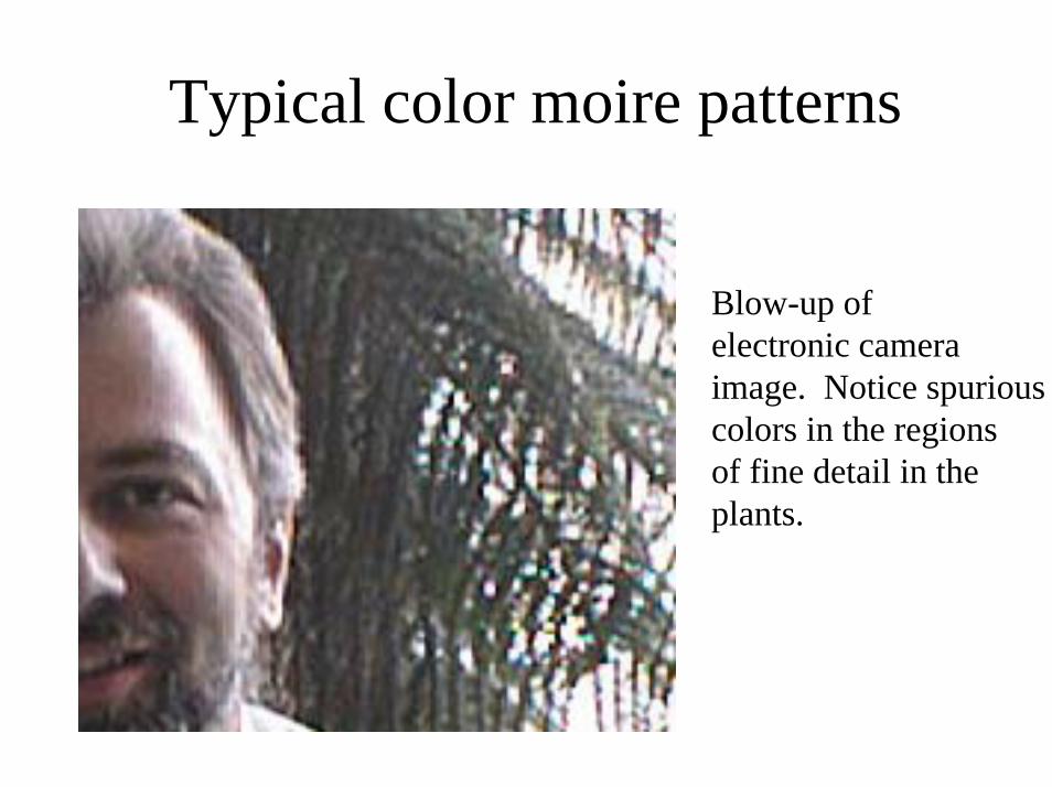
Typical color moire patterns
Blow-up of electronic cameraimage. Notice spuriouscolors in the regionsof fine detail in the plants.
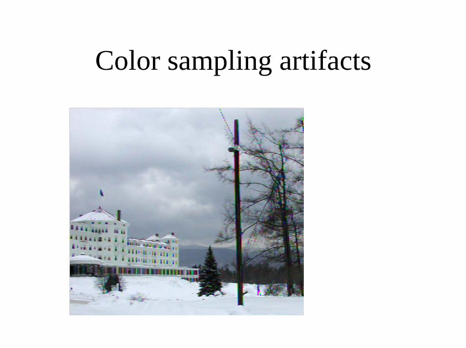
Color sampling artifacts
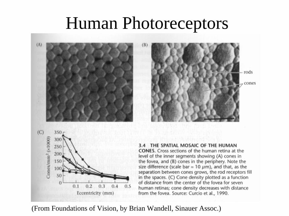
Human Photoreceptors
(From Foundations of Vision, by Brian Wandell, Sinauer Assoc.)
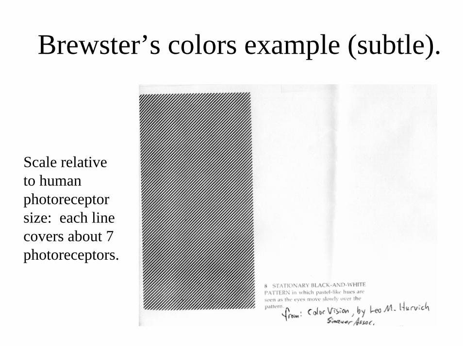
Brewster’s colors example (subtle).
Scale relativeto humanphotoreceptorsize: each linecovers about 7photoreceptors.

Median Filter Interpolation
• Perform first interpolation on isolated color channels.
• Compute color difference signals.• Median filter the color difference signal.• Reconstruct the 3-color image.
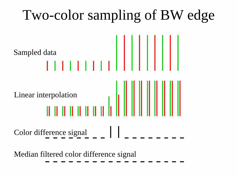
Two-color sampling of BW edge
Sampled data
Linear interpolation
Color difference signal
Median filtered color difference signal

R-G, after linear interpolation
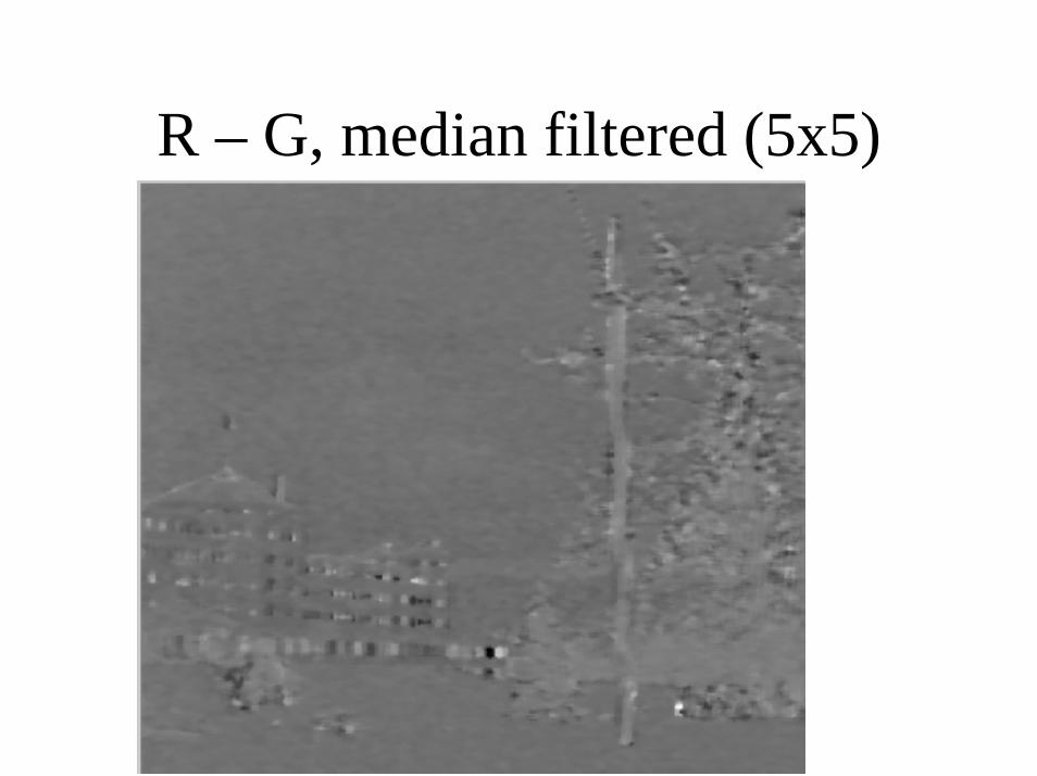
R – G, median filtered (5x5)
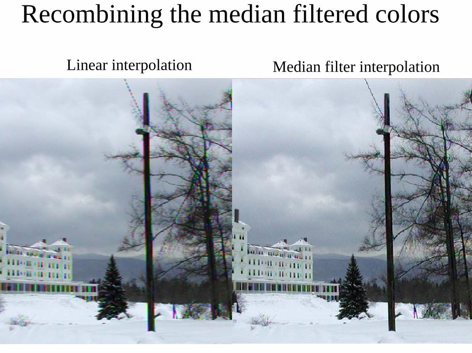
Recombining the median filtered colors
Linear interpolation Median filter interpolation