COMPUTER VISION CAPABILITIES FOR A SEMI...
85
COMPUTER VISION CAPABILITIES FOR A SEMI-AUTONOMOUS WHEELCHAIR by JEREMY TARVER (Under the Direction of Walter D. Potter) ABSTRACT The semi-autonomous wheelchair uses a multi-layered intelligent agent architecture designed to provide people with severe multiple disabilities navigational assistance in indoor environments. This paper describes the addition of computer vision capabilities to the semi- autonomous wheelchair. Specifically an intelligent agent design is described which detects doorways in indoor environments and provides the location to the user via a tactile interface. A prototype is developed that demonstrates the software architecture is capable of operating in a real time environment. INDEX WORDS: Artificial Intelligence, Computer Vision, Assistive Technology, Doorway Detection
-
Upload
truongnguyet -
Category
Documents
-
view
220 -
download
1
Transcript of COMPUTER VISION CAPABILITIES FOR A SEMI...
COMPUTER VISION CAPABILITIES FOR A SEMI-AUTONOMOUS WHEELCHAIR
by
JEREMY TARVER
(Under the Direction of Walter D. Potter)
ABSTRACT
The semi-autonomous wheelchair uses a multi-layered intelligent agent architecture
designed to provide people with severe multiple disabilities navigational assistance in indoor
environments. This paper describes the addition of computer vision capabilities to the semi-
autonomous wheelchair. Specifically an intelligent agent design is described which detects
doorways in indoor environments and provides the location to the user via a tactile interface. A
prototype is developed that demonstrates the software architecture is capable of operating in a
real time environment.
INDEX WORDS: Artificial Intelligence, Computer Vision, Assistive Technology, Doorway
Detection

COMPUTER VISION CAPABILITIES FOR A SEMI-AUTONOMOUS WHEELCHAIR
by
JEREMY TARVER
B.S., University of Georgia, 2002
A Thesis Submitted to the Graduate Faculty of The University of Georgia in Partial Fulfillment
of the Requirements for the Degree
MASTER OF SCIENCE
ATHENS, GEORGIA
2008

© 2008
Jeremy Tarver
All Rights Reserved

COMPUTER VISION FOR A SEMI-AUTONOMOUS WHEELCHAIR
by
JEREMY TARVER
Major Professor: Walter D. Potter
Committee: Khaled Rasheed Pete Bettinger
Electronic Version Approved: Maureen Grasso Dean of the Graduate School The University of Georgia May 2008

ACKNOWLEDGEMENTS
I would like to thank the open source community, whose labors to create free (as in
freedom) software have created tools that make scientific progress easier. This research would
not have been possible without my colleagues who assisted in various stages of the wheelchair
project, Hajime Uchiyama, Dr. Covington, Robert Eunice, and Dr. Potter. I also thank my
family, friends, and especially my loving wife for support and encouragement through the
travails of this journey.
iv

TABLE OF CONTENTS
Page
ACKNOWLEDGEMENTS ........................................................................................................... iv
CHAPTER
1 INTRODUCTION .........................................................................................................1
Motivation .................................................................................................................1
Problem Statement ....................................................................................................2
2 BACKGROUND ...........................................................................................................3
Computer Vision .......................................................................................................3
Computer Vision in Wheelchair Systems .................................................................4
Doorway Detection ....................................................................................................9
Problems with Prior Work ......................................................................................13
3 DESIGN .......................................................................................................................15
Design Overview .....................................................................................................15
Doorway Candidate Search .....................................................................................18
4 IMPLEMENTATION ..................................................................................................23
Chapter Overview ....................................................................................................23
Control Architecture ................................................................................................23
Vision Module .........................................................................................................24
v

vi
Communication Protocol .........................................................................................25
Software Architecture ..............................................................................................26
Doorway Candidate Search .....................................................................................27
5 RESULTS ....................................................................................................................39
Results .....................................................................................................................39
Execution Time and Performance ...........................................................................45
6 CONCLUSION ............................................................................................................46
Summary .................................................................................................................46
Future Work ............................................................................................................46
REFERENCES ..............................................................................................................................48
APPENDICES
A SOURCE CODE FOR DOORWAY CANDIDATE DETECTOR .............................52
B OPENCV FUNCTION REFERENCE ........................................................................73

CHAPTER 1
INTRODUCTION
1.1 Motivation
Individuals in powered wheelchairs with multiple disabilities face extreme challenges to
their personal autonomy. Their ability to live more independently and with a higher quality of
life could be increased by intelligent assistive technologies. Currently there are no commercial
systems that users could benefit from. Since the fall of 2002 the University of Georgia's
Artificial Intelligence Center has been involved in the design and implementation of an
intelligent wheelchair system. The semi-autonomous wheelchair project is large in scope, and
represents a collaboration of several researchers. The project started when we received a request
from a student at UGA who was both visually and mobility impaired, and was seeking
technologies that would provide her with more autonomy. Some of the goals we identified
through interviews include obstacle detection and avoidance, doorway navigation, and
acquisition of guidance information such as room numbers and signs. We aim to develop an
intelligent system to assist users with multiple disabilities in core day-to-day activities.
The activities the project will focus on include assisted navigation in indoor
environments aided by sensory augmentation rather than fully autonomous control. The sensory
enhancement includes basic level features such as notification of nearby obstacles, indications of
path of least obstruction (help navigate out of a crowded space), and discovery of doorways.
1

2
1.2 Problem Statement
The design and implementation of the semi-autonomous wheelchair system is described
in Perceptual Navigation for Semi-Autonomous Wheelchair Operations [Uchiyama, 2008]. The
system is comprised of individual sensing agents which collectively can be coordinated to
achieve high levels of intelligent behavior, such as finding free space in a crowded corridor or
assisting the user through the navigation of a doorway. Based on the needs of the user we
interviewed, our prototype is specifically tailored to a mobility impaired user with severe visual
impairment but fine motor control of the upper extremities and fully capable cognitive abilities.
We aim to extend the capabilities of the semi-autonomous wheelchair system to provide
computer vision capabilities. The eventual aim for our semi-autonomous wheelchair project is
assisting users in the navigation of doorways; this project represents the first steps toward
accomplishing that task. The goal of this project is to design the software architecture necessary
to accurately classify doorways in a real time environment as well as the implementation of a
prototype system for a real-time search for doorway candidates.
In order to perform high level object detection and classification such as doorway
detection in a real-time environment, a number of complex processing stages and an efficient
algorithmic implementation are required. The combination of constraints requiring a low cost
system, quick processing in a real time environment and effective operations in a noisy
environment including obstructions makes for an extremely challenging problem.
.

CHAPTER 2
BACKGROUND
2.1 Computer Vision
Computer vision deals with the theory and process of obtaining information from images.
It lies at the nexus of artificial intelligence, robotics, signal processing, optics, and machine
learning. Computer vision is closely related to the fields of image processing and machine vision
and shares many of the same principles and techniques.
Image processing tends to focus on 2D images, typically how to transform a source
image to another image. Such operations can include image enhancement or compression, color
conversions, or geometrical transformations. Image processing mainly focuses on these
transformations, rather than extraction and analysis of information from images [Jain et al.
1995].
Machine vision has been defined as “…the study of methods and techniques whereby
artificial vision systems can be constructed and usefully employed in practical applications. As
such, it embraces both the science and engineering of vision" [Davies 2004]. Machine vision
often distinguishes itself from computer vision by the typically more industrial application of
computer vision processes.
Computer vision can be differentiated by the attempt to extract information from an
image scene, which often involves higher level classification tasks. Despite the slight
distinctions between them, there is much overlap in terms of principles and techniques. This
implies that they could be essentially considered as the same field, but the distinctions may be
3

necessary in order to focus research and publication materials due to the tremendous scope of
information available from visual images.
2.2 Computer Vision in Wheelchair Systems
The TALOS project was undertaken at ICS-FORTH in Greece. To my knowledge it
represents the first usage of computer vision for assistive technologies. The purpose of the
project was to provide semi-autonomous navigational assistance to users of powered
wheelchairs, specifically targeted navigational assistance [Trahanias et al., 1997]. In this case
the intention was to allow the operator to choose a target from an image of the local environment
which the wheelchair then attempts to navigate towards.
The interface consists of a visual display by means of which images captured from the
cameras are displayed to the user. The user is able to select a target in the image by means of a
pointing device. Once a target is selected the navigation process is given over to the system.
The system achieves navigation toward the target selected by the user by an internal hierarchical
motion planner. Essentially the wheelchair directs itself towards the target selected in the image,
if an obstacle is encountered by the sonar/IR sensors a routine for obstacle avoidance is invoked
which overrides the global planner. This is an example of the subsumption architecture proposed
by Brooks [1986].
The computer vision algorithm works essentially by creating a color histogram of the
targeted region in the image. The histogram of the target region and a small window
surrounding it is referred to as a template. Regions of subsequent images are compared to the
target template by a sum of squares difference criterion. The location of the best fit in the new
image is defined as the new target, and the template is updated. The direction of the target in
4

regards to center of the image (direction the camera is pointing) is easily obtained. The direction
is given by arctan(x/f), where x is the centroid of the template and f is the focal length of the
camera. This is both the angle the camera needs to pan in order to fix the template in the center
of the image and the direction the wheelchair itself needs to go. The implementation of their
design includes 2 separate processors, a Pentium for computer vision and control of the camera
positioning system, and a 486 processor for controlling the wheelchair motion and the other
sensors attached to the system. The implementation does not address the issue of autonomous
object detection and classification, but rather relies on the user to select a region in the image
after which the software tracks the region of interest.
A project using a panoramic vision system was implemented at ICS-FORTH in Greece
[Argyros et al., 2002]. A powered wheelchair is again used as the platform for the system. The
sensors include an odometer for tracking wheelchair motion, 6 sonar units, a microphone, and
most importantly a Neuronics panoramic camera with a parabaloid mirror and a 360 field of
view. The purpose of this project is like the previous in that it is aimed at semi-autonomous
navigation. The user is able to direct the motion of the wheelchair via voice commands towards
a particular direction, or use a visual display to select a target region for the system to navigate
towards. This also includes the following of a moving target such as a person.
The use of a panoramic camera has several advantages. It allows for simultaneous access
to visual information in a complete 360 range surrounding the platform. Traditional camera
systems require pan/tilt systems to focus the camera in order to gather visual information about a
region that is not currently in view. The hardware and software to control the movement is an
additional time and design cost that is avoided with the use of a single camera capable of a 360
view.
5

However the use of a panoramic camera is not without its own costs, it requires
additional software processing in order to account for the different properties of the image.
Traditional images can benefit from the large existing libraries of vision processing techniques
available, whereas techniques and libraries for omni-directional image processing are not readily
available. The omni-directional camera is also much more expensive than traditional cameras, as
of 12/10/2007 a typical quoted price runs around $2,000.
The implementation of their prototype used the sonar sensors to calculate the distance to
the moving object targeted by the vision system. The vision system would calibrate the direction
of the target, and the sonar system would calculate the distance. This represents a nice
combination of two levels of sensors, and the technique could be applied to estimate distances
without relying on the complexities of stereo vision. As in previous research the higher level
system of targeted navigation is subsumed by obstacle avoidance techniques if hazards are
encountered. The target is also similarly recognized, a color histogram is used, but this time with
the addition of 3 regions representing the head, torso, and legs of the human body.
A major downside to the approach of using only color histograms is that it is reliant upon
the color of the target being sufficiently different from the color of the background. For example
if the system followed a target wearing a white shirt, whenever the target crossed in front of a
white wall or corridor the system could no longer find and track the target. This approach also
relies on the selection of a target of interest by the user, and does not attempt to detect and
classify objects autonomously.
The aims of the TAO project involve the development of an add-on system to powered
wheelchairs to increase the autonomy of the user [Gomi and Griffith 1998]. Some of the tasks
undertaken in its development include basic collision avoidance, corridor navigation, doorway
6

navigation, escape of tight situations, and landmark based navigation. The TAO 1 sensors
include 2 CCD color cameras, 3 bump sensors, and 12 IR sensors. It uses one processor used for
the vision system and another for the other sensors and subsystem.
The vision system is used to calculate the depth and size of free space in the area near the
wheelchair, the vanishing point, and indoor landmarks. The vision processing receives as input
two 256x128 images and operates at a rate of about 8 frames per second. The image from each
camera is divided into sections left/right/center, and then the two images are averaged down to a
64x32 pixel image. Subsequent processing occurs on this averaged down image. The technique
for obtaining depth values is called Horswill's habitat constraint vision processing. Other
information obtained from the vision sensors is the vanishing point and area detection (for
determining amount of free space).
The Wheelesley project from MIT is based on the Tin Man II prototype [Miller and Slack
1995], and aims to provide navigational assistance to powered wheelchair users in both indoor
and outdoor environments. The early work published on Wheelesley describes the GUI used to
interface with the control system, with the underlying sensors and capabilities being essentially
the same as the Tin Man [Yanco et al., 1995]. Later work describes the addition of a stereo
vision system to be used in outdoor navigational assistance [Yanco 2001]. Principally the two
images were compared for difference between points, thus generating a disparity map. An edge
detector was applied to the disparity map and significant changes in gradient are classified as
obstacle boundaries.
A technique was also implemented for following a sidewalk by using edge detection, then
fitting a line to edge points on the left and another line to edge points on the right, with the
requirement that at least 8 points must fit the line. It appears that the array of other sensors
7

available on the Tin Man platform was never used in the implementation, but rather obstacle
detection relied entirely on computer vision. The two functions described in this paper are
sidewalk following and an inferior implementation of obstacle detection.
The vision system described could be useful as an addition for obstacle detection,
particularly in situations relating to drop off detection where sonar would fail. Vision is a very
high level and computationally intense information pathway, for simple tasks such as detecting
obstacles the primary tool should be sonar whenever possible due to its low complexity,
monetary, and computational cost.
Since the fall of 2002 the University of Georgia has been involved in the creation of a
semi-autonomous wheelchair to assist individuals with multiple disabilities. Foundational work
was done on the project by Yuki Ono, who did experimental work on the design of a control
system for a robotic platform. His approach involved a multi-agent system with different
components to handle sensors, computer vision, locomotion, and collision avoidance [Ono et al.,
2004]. The hardware consisted of a commercial robot kit called the ERI Personal Robot System.
It is a small robotic kit including a chassis, power supply, wheels, motors, and a collection of
sensors. The sensors include 3 infrared sensors, a microphone, and a web camera. The kit is
controlled by a laptop which sits on top of the chassis.
This platform was used to develop software to attempt to solve some of the problems
involved with corridor navigation. The web camera was used to acquire images which were
processed to determine if the location was a corridor. A 160x120 color image was converted to
grayscale, after which it was smoothed with a Gaussian filter. Then a Sobel operator was applied
to enhance the edges, followed by binary thresholding and a thinning operator. The final step
8

was a Hough Transform to detect candidate lines which conformed to the geometry expected of a
corridor.
2.3 Doorway Detection
The detection of doorways is a critical component to robot navigation in structured
environments. The recognition of a doorway gives important information for autonomous or
semi-autonomous vehicles. This section examines different approaches used in detecting
doorways, and discusses the advantages and disadvantages of different approaches.
In Stoeter et al. [2000], a mobile robot captures camera images 380x280 pixels in size.
A Sobel filter is applied to detect edges then the edge image is thresholded to eliminate weak
edges. Dilation is a morphological operator which essentially causes objects to grow or dilate in
size. Erosion has the opposite effect, it causes objects to shrink. Combining these two operators
in sequence was used to close line segments. Once the vertical segments were obtained, the
locations of possible doorways were reported based on the expected dimensions of doors and the
corridor parameters. The corridor parameters were the direction and distance of the wall with
respect to the robot. The direction and distance to the wall were obtained by locating the line
intersection of the floor with the walls. On a 166 Mhz processor the robot processed roughly one
image per second. The computer vision techniques were combined with sonar readings to verify
if the door was open or closed.
This technique has several advantages, namely its speed, especially considering that
current processors are roughly 15 times faster. Another advantage is that it takes into account a
very important property of doorframes that most other techniques using a single camera do not;
the corridor dimensions and the relationship of the frame to the wall. The drawback to the
9

authors’ method is that it only detects the vertical bars and the relative distance between them
(and corridor parameters) to classify an object as a doorframe. This means that any two strong
vertical lines sufficiently apart will be falsely classified as a doorframe, and does not take into
account addition features such as the lintel. Therefore the edges of an inset wall containing a
water fountain would be falsely classified as a doorway, as would a wide painted vertical stripe
extending from the floor to the ceiling.
Monasterio et al. used a single camera to obtain images 160x120 pixels in size. Very
similar to the work done by Stoeter et al., a vertical Sobel filter was applied to the image in order
to capture the strong vertical lines of the doorframe. The image was filtered again with a dilation
filter and afterwards columns separated by thin spaces are merged. If a column was wider than
35 pixels, it was determined to be a doorway. This approach has several disadvantages, it is not
adaptable to changes in perspective, the camera must be close enough to the door (within 2
meters) so that the vertical sides are sufficiently apart, and again any two sufficiently strong
vertical lines sufficiently apart would be falsely identified as a doorway.
Another approach taken has been to classify doorways by recognizing components of the
doorway as identified by neural networks Ciricelli et al. [2003]. Two neural networks were
trained to detect components by color. First the image was translated from the RGB color space
to HSV color space, which represents Hue, Saturation, and Value. Next the Hue and Saturation
channels for an 18x18 pixel sub-window of the image were fed into a neural network. The
components that were searched for include both the top right and left corners and the vertical and
horizontal bars. First a neural net was trained for the upper left corner, and then the same net
was used to detect upper right corners by simply flipping the image. The same technique was
used to detect the vertical and horizontal bars of the doors. Each sub-window is shifted by two
10

pixels, (not tiled) so for one scan there are (a seemingly excessive) 98820 of sub-windows tested
by the network. A voting scheme was used to prevent false positives. After the corners and bars
were detected, a heuristic was used to determine if there were sufficient components of the door
present to be considered a door.
The advantage to this method is that it is (at least in the component stage) not based on
heuristics, but the neural network is trained by real examples and constitutes true machine
learning. The corner and bar detectors are also able to positively identify corners and bars that
are slightly off in terms of angles, so it is perspective and scale insensitive. A large disadvantage
of the system is the computational cost in detecting the components. This drawback could be
improved by using a gray-scale image rather than color, for the color of doors is variant, and the
number of input nodes to the neural network could be reduced by half. Furthermore the gray-
scale image could be convolved with an edge detector and optionally thresholded before being
input to a neural network. For the corner detector rather than a binary output the neural net could
be trained to output the pixel closest to the absolute corner. Also more aggressive shifting
should be done, so rather than a shift of only 2 pixels and having excessive overlap, a shift of at
least 1/3 the size of the sub-window would significantly decrease the computational complexity.
In Snaith et al., [1998] the authors propose a system to assist blind users to detect
doorways by means of a camera mounted on the shoulder. First the search area was constrained
by sparse scanning of the image by means of two horizontal lines which divide the image into
thirds. The grayscale value of the two lines was used as the two input vectors to a linear
correlation. If the linear correlations exceeded a threshold, six further equally spaced lines were
scanned. These lines (and their immediate vertical neighbors) were convolved with a vertical
3x3 Sobel operator. The output was fed into a simple threshold based transition detector to
11

detect the horizontal position of major transitions. All of the lines are then searched for pairs of
lines or transitions which have the expected separation which a doorframe would. Starting from
the first likely point found, lines beneath it were searched in a half angle cone of 5 degrees
(allowing the camera to be not entirely vertical). The results made up a matrix of arrays of
candidate points which may represent a vertical doorframe line. Each array was then searched to
determine covariance with respect to the start pixel. Classification was then performed on the
candidate line based on the number of matching pixels. Lines that had all matching pixels were
deemed primary, and lines with 2/3rd’s pixels matching were considered secondary. When an
image was found that had 2 secondary lines sufficiently apart, or a secondary with a primary, or
two primaries, further processing was performed. The region between the top of the candidate
lines was searched using the same method as previously described, but this time the search was
performed for horizontal lines. If a primary or secondary horizontal line was found, the group of
lines was classified as a doorframe. The computational cost seems very reasonable, as the
authors were able to achieve a rate of about 1 frame per second, on a 486 PC running Windows
3.1. This technique seems promising because it is robust to occlusion. The covariance matching
technique is unfortunately sensitive to changes in illumination, and requires near constant
illumination across the image. The technique is also susceptible to classifying any large
rectilinear object, such as a large cabinet, as a doorway.
In Muñoz-Salinas et al., [2004] a real time system for the detection of doorframes was
developed using fuzzy logic. First a Canny Edge Detector was applied to the image followed by
a specialized Hough Transform [Foresti 2000] to extract line segment information. Two
configurations were detected, a single doorframe and a double doorframe (caused by either the
door being closed, or a wide moulding on the edges of the frame). The authors used fuzzy logic
12

to categorize line segments and their relationship to each other, and thereby classified objects as
a doorframe or not. This method is insensitive to perspective or color, and is capable of working
at an experimented rate of 6 frames per second on a 320x288 image. On a Pentium 4 2.4 Ghz
processor images took on average 160 ms. These processing speeds make the technique
applicable to real time doorway detection; however it was not demonstrated in a real time
environment. The authors later modified the parameters used to check for fuzzy concept
membership in a separate paper [Muñoz-Salinas et al., 2006], where they tuned the thresholds
using a genetic algorithm. They also modified the possible classifications defining a Frame
Edge, Door Frame, and Frame Edge with Evidence. This approach is the best attempt so far to
classifying potential doors in a single image with no depth information.
2.4 Problems with Prior Work
The previous approaches detailed above fail to fully address the problem of doorway
classification. We can evaluate the incompleteness of prior work based on scene conditions that
would cause a misclassification of a doorway. The following scenes will be used to evaluate
previous approaches: a large cabinet the size of a doorway (complete with handles and hinges); a
large painted vertical stripe on a corridor wall; and finally a store with model door units on
display. Table 2.1 categorizes previous approaches based on these situations.
Table 2.1: Scene limitations of prior work
Cabinet Vertical Stripe Door in the Store Monasterio Cicirelli Snaith Munoz-Salinaz Stoeter
13

14
Approaches taken by Monasterio and Stoeter do not search for the lintel of a doorway,
thus they are vulnerable to classifying a large painted vertical stripe on a corridor wall as a
doorway. Approaches such as those by Monasterio, Cicirelli, Snaith, and Munoz-Salinaz which
do not calculate distance information and ignore the relationship of the doorway in relation to the
plane of the wall are vulnerable to classifying a large cabinet as a doorway. One might argue
that a highly refined feature identifier could be designed to distinguish between the door of a
large cabinet and a standard door. Let us assume for a moment that such a system exists and it
can distinguish between a large cabinet door and a standard door. Now imagine the user of such
a system navigating through a store that sells doors. The model door units on display would
match every qualifying feature derivable from a two dimensional image, even though the model
door units are not in fact doorways. One could argue that the likelihood of such a situation
occurring is small enough such that this situation could reasonably be ignored. However rare the
situation may be, to ignore it would be to miss a fundamental characteristic of doorways
highlighted by this situation. The key feature that distinguishes the model door units from a
navigable doorway is that they are not embedded in the plane of a wall. Doorways by their very
nature are designed to be a movable barrier to selectively prevent or allow passage through the
plane of a wall. Therefore approaches which do not take distance and planar information into
account, even if sufficiently tuned to distinguish between large cabinets and standard doors, will
nevertheless fail the “Door in the Store” problem.

CHAPTER 3
DESIGN
3.1 Design Overview
The previous section detailed prior work in detecting doorways and the unsatisfied
problems of the previous approaches. We identified the necessity of both detecting doorways by
their position with respect to the plane of a wall and their geometric features. To obtain the
requisite distance information we will utilize the laser range finding unit described in Perceptual
Navigation for Semi-Autonomous Wheelchair Operations [Uchiyama, 2008]. Our system
incorporates a low cost web camera with a horizontal laser line generator allowing the detection
of laser points in the image to be identified and based on the technique of triangulation converted
to distance measurements.
It is desirable in the operation of the laser line generating unit to activate it intermittently
in order to both consume less power and prevent the unit from overheating. Therefore our
design calls for a two stage approach to doorway detection. The first stage is the Doorway
Candidate Search which will rely only on the web camera to search for doorway candidates
based on features derived from the monocular image. If a doorway candidate is detected the
second stage will be activated which is Doorway Verification. Doorway Verification will
involve activating the laser range finding behavior in order to obtain the distance data necessary
to calculate both the doors exact dimensions and its parameters with respect to the wall. Figure
3.1 shows the design overview of the Doorway Detection and Notification process.
15

Figure 3.1: Stages of Doorway Detection System
16

The start node represents initiation of the doorway detection system, and will be invoked
when the semi-autonomous wheelchair is in general navigation mode. The first process is the
search for doorway candidates. In this stage video frames are continually being retrieved from
the camera unit and processed in order to detect potential doorways. The pan/tilt system is used
to pan the camera unit back and forth in the search process. If an image contains a doorway
candidate, the Doorway Verification routine is then invoked.
The Doorway Verification process may choose to pan or tilt the servo motors to focus
more directly on the potential doorway, after which it activates the laser line generator and
acquires an image from the camera unit. The newly acquired image containing the laser line is
passed to the Range Finder. The Range Finder locates the laser points in the source image and
based on the pixel coordinates will transform the coordinate values into a real-world distance
measure. The result is a one dimensional array of distance values whose length is equal to the
width of the image. Therefore each column in the original image will have a corresponding
distance measurement associated with it. When the distance values are computed the array of
range values is returned to the Doorway Verification unit.
If the doorway candidate is verified, then the distance and direction to the center point of
the doorway is sent to the Notify User process. The Notify User process will send signals to the
glove microcontroller to vibrate the motors that correspond to the proper direction and distance
of the detected doorway. The detection and notification process ends once the user has been
notified of the location of the doorway.
17

3.2 Doorway Candidate Search
The process of extracting information from an image is one that involves a series of
stages. The design is described below in a step by step method, with a section devoted to each
stage in the computer vision process. The following stages of the design will be discussed:
preprocessing, detecting edges, extracting line segments from the edge images, and finally
matching the lines together to classify doorway candidates.
Preprocessing often involves image transformation as preliminary steps in order to
decrease the overall order of magnitude of the operations performed over the course of
information extraction. If a number of operations has to be performed on an NxN array for each
of the several stages, then the time involved is on the order of O(S x N2), where S is the number
of operators which have to be applied to each pixel in the image. Since N dominates S the
reduction in the size of N is very desirable for reducing computational cost. Therefore the first
step of preprocessing will be to reduce the image size by half; from the original 640x480 to
320x240 pixels.
The second method of reducing computation time is a conversion from color to greyscale.
Typical color images are composed of three channels, an array for red values, an array for green
values, and an array for blue values. Some images also include a fourth array for alpha, or
transparency values, but it is not the case with the images we will capture. Since color is also not
necessary to detect the geometrical properties of the doorframe, we can reduce these three
channels to a single channel representing only a greyscale value. By reducing three channels of
color information representing a pixel to a single value, the number of operations is reduced by
another factor of three. The number of operations after these preprocessing steps have been
made is therefore reduced from (S x N2), to (S x (N/6)2).
18

Edge detection is the next stage in processing images from the indoor environment. Edge
detectors work by finding and enhancing large differences in adjacent pixel values. The Sobel
operator is a commonly used method in detecting or enhancing edges. It works by
approximating the first order derivative which expresses the gradient of the image intensity at
each point. The way this works is that the original image is convolved with a 3x3 kernel. For
the enhancement of vertical edges (the horizontal derivative) the kernel used is shown in Figure
3.2. For horizontal edges the kernel is shown in Figure 3.3.
-1 0 1
-2 0 2
-1 0 1
1 2 1
0 0 0
-1 -2 -1
Figure 3.2: Vertical Sobel Kernel
Figure 3.3: Horizontal Sobel Kernel
The usage of these operations on an image is best imparted with visual examples, so the
following will demonstrate their effects on the source image in Figure 3.4. Figure 3.5 is the
result of applying the vertical Sobel filter, and Figure 3.6 is the result of the horizontal Sobel
filter.
19

Figure 3.4: Original Image
Figure 3.5: Vertical Sobel Filter Applied Figure 3.6: Horizontal Sobel Filter Applied
Another commonly used technique is the Laplacian operator. It works by computing the
second derivative of the intensity image and finding the zero crossings. Figure 3.7 shows the
standard kernel used for the Laplacian operator. An advantage to the Laplacian is that it results
in thinner lines than the Sobel operator; however it is also sensitive to noise. To resolve this
issue typically a smoothing filter is applied to the image to reduce noise. The Gaussian filter is
20

most often used for this step; it acts by using a normal distribution to transform each pixel which
has the effect of averaging pixels to achieve a blurring or smoothing effect. Figure 3.8 shows the
result of applying a 3x3 Gaussian smoothing filter followed by the Laplacian operator.
Figure 3.8: Original Image
1 1 1
1 -8 1
1 1 1
Figure 3.7: Laplacian Kernel
Once the stage of edge detection has been completed the next task is to try and extract
straight lines from the pixels that represent edges in the original image. The task of grouping
edge pixels into corresponding sets of features, even simple ones like straight lines represents a
significant problem. Due to noise or inaccuracies from the image data, there are often gaps in
pixels or edges that are noisy. The Hough Transform is a technique that is designed to overcome
the imperfections in the edge image by the means of a voting process. In essence each edge
pixel is examined and is allowed to cast a vote about the lines it could possibly lie upon. Since
vertical lines when represented by the slope-intercept form have a slope approaching infinity,
21

22
this form of representation is avoided in favor of polar coordinates. Polar coordinates are a
means of representing a line’s location in a Cartesian plane by an angle measure (θ) and a
distance measure (ρ). The distance measure is the distance from the center of the coordinate
system along a line that lies perpendicular to the line that is being described. The votes from
each pixel are stored in an accumulator array. The accumulator array, also known as the Hough
space, is indexed by the ρ and θ values. Strong lines in the image will have many edge pixels
voting for them, and thus will be represented as peaks in the Hough space. After the voting
process is complete, the Hough space is searched for local maxima in order to detect lines in the
image.
The last stage in the process is classifying doorways based on the line segment
information. The classification is made by matching two lines that are vertical and of sufficient
distance apart that are also joined by a horizontal line. The allowable amount between line
endpoints to be considered as “connected” will be experimentally derived. Once all of the
conditions have been satisfied with regards to line structure and placement, the location of a
potential doorway is signaled. Note that the doorway could be open or closed, and this technique
will also allow for partial occlusion of the lower regions of the doorframe, for instance when a
person or object partially obscures the view of the doorway. However it should be noted that
doorways that do not have a straight lintel, but rather an arched one, will not be classified by the
doorway candidate search.

CHAPTER 4
IMPLEMENTATION
4.1 Chapter Overview
Since the design and physical embodiment of the semi-autonomous wheelchair has been
detailed in previous work [Uchiyama, 2008], this section will briefly provide an overview of the
Control Architecture and the Vision Module, and then introduce a new protocol design for
communication between the sensors, controllers, and actuators. Next the software architecture of
the computer vision system will be outlined, followed by a detailed description of the processing
stages involved in the Doorway Candidate Search implementation.
4.2 Control Architecture
The semi-autonomous wheelchair system is comprised of three control processor
architectures. The first and highest level of processing is performed by an on-board laptop which
we refer to as the "host computer". The host computer sits beneath the chair and interfaces with
the additional processing units which act as intermediaries in the sensory processing and control
stages. The second is a custom micro-controller designed by Dr. Covington to activate the
vibrations of the tactile glove. We refer to this as the “glove controller”. The glove controller
accepts signals from the host computer via a serial connection. The third is a microcontroller
which handles the rest of the interactions between the sensors, the actuators, and the host
computer. We refer to this as the “Main Controller” due to its dominant role in the
sensor/actuator control scheme. The bulk of the interactions between sensors, actuators, and the
23
host computer are mediated by the Main Controller, a Rowley Associates LPC2138. The Main
Controller collects input from the sonar sensor array, accelerometer, and gyroscope. It also
offers the ability to control functions such as turning the horizontal line laser on and off, and
sending control signals to move the pan/tilt servo module. The Main Controller is connected to
the host computer by a USB connection which delivers both power and control signals.
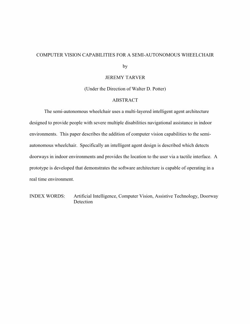
4.3 Vision Module
In addition to the sensors connected to the Main Controller, the host computer also is able
to obtain visual information from the environment via a direct USB connection with a Logitech
Quickcam Pro 4000. Figure 4.1 shows the physical configuration of the computer vision
module.
Figure 4.1: Computer Vision Module
24

The laser is mounted atop of the pan/tilt module which is secured to a custom designed
aluminum frame over the back of the wheelchair. Extending upwards from the laser
approximately 12" is an extension of the frame which attaches to the camera unit.
4.4 Communication Protocol
The host computer communicates with the Main Controller by means of a custom
communication protocol. Our design is capable of representing all of the control signals
necessary for the actuators in addition to representing the information gathered from the sensors.
Thus the protocol is a two-way device for communicating both commands and data. The Main
Controller operates on 32 bit instructions, thus the communication protocol is based on a 32 bit
packet containing a header, type, and value. The first eight bits of the packet represent the
header, which is an indication to the processor that a new signal is beginning, and the instruction
type and data payload are following. The next eight bits represent the packet type, which can
indicate any one of the following types of information: pan, tilt, laser, sonar, gyroscope, or
accelerometer. The last 16 bits contain the data payload, which in the case of a sonar packet will
represent different sonar distance readings, or in the case of pan or tilt packets represent a control
value indicating the degrees that the servo motors will move. An example packet is shown in
Table 4.1. Table 4.2 represents a list of the packet types and their descriptions.
Table 4.1: Communication Protocol Packet Descriptors
Header ID Data
10000001 00000001 0000000010110100
0x81 Pan[Fixed] 180°
25

Table 4.2: Communication Protocol Packet Descriptors
ID Type Description 1 Pan [Fixed] Move the pan servo motor to a fixed point on a 360° system 2 Pan [Relative] Move the pan servo motor N degrees relative to the current
position 3 Tilt [Fixed] Move the tilt servo motor to a fixed point on a 180° system 4 Tilt [Relative] Move the tilt servo motor N degrees relative to the current
position 5 Laser Activate/Deactivate 6 Sonar 0 Value reading from sonar sensor 7 Sonar 1 Value reading from sonar sensor 8 Sonar 2 Value reading from sonar sensor 9 Sonar 3 Value reading from sonar sensor 10 Sonar 4 Value reading from sonar sensor 11 Sonar 5 Value reading from sonar sensor 12 Sonar 6 Value reading from sonar sensor 13 Sonar 7 Value reading from sonar sensor 14 Sonar 8 Value reading from sonar sensor 15 Gyroscope Value reading from Gyroscope 16 Accelerometer Value reading from Accelerometer
4.5 Software Architecture
Figure 4.2 shows a schematic of the Software Architecture Layers involved in our
implementation of computer vision capabilities for the Semi-Autonomous Wheelchair. The base
layer is the operating system. We chose Linux early on as an ideal candidate for an operating
system due to its open nature which allows for maximum configurability. In a real time
environment the ability to limit running processes to a minimum provides extra processing time
available for our own software stack in addition to freeing up other resources. The next software
layer is a set of library functions made available by Intel. Called Intel Integrated Performance
Primitives (Intel IPP), these libraries offer highly optimized functions for multimedia data
processing and communications applications. Specifically the functions that we are interested in
provide an extremely fast set of functions for low level image manipulation. On top of the
26

performance primitives is an open source library called OpenCV. This library is also released by
Intel, and it includes many extremely useful functions for real time computer vision applications.
The topmost layer in the software architecture is our custom code designed to implement the
stages required in doorway classification. Figure 4.2 displays three custom software modules:
Doorway Detection, Range Finder, and Door Verifier. Naturally other modules can be added to
this layer as necessary, these three are chosen for their direct relevance to the Doorway Detection
System.
Figure 4.2: Software Architecture Layers
4.6 Doorway Candidate Search Overview
The implementation of the Doorway Candidate Search will be described in the following
sections. Each section corresponds to a stage in the processing required to extract information
about doorway candidates. The stages of implementation that will be described are
27

Preprocessing, Edge Detection, Line Segment Extraction, Merging Line Segments, and Doorway
Candidate Classification. The OpenCV library functions used to perform stages of the image
processing pipeline will be included in the discussion.
4.6.1 Preprocessing
Preprocessing is the stage in computer vision where operations are undertaken to prepare
the image for further analysis. The first step in the preprocessing phase is the reduction of the
image size. The prototype camera we are working with has a maximum resolution of 640x480,
and we capture images at the maximum resolution. This allows the possibility of performing
future operations that require crisp images or fine details. However the detection of strong lines
comprising doorframes is not one of those applications requiring high resolution, so we can
reduce its size by one half and achieve a very significant reduction in time complexity. The
image is reduced in size and simultaneously convolved with a Gaussian smoothing filter in order
to reduce noise in the image. The function cvPyrDown convolves the source image with a 5x5
Gaussian filter and then down samples the image by rejecting even rows and columns. The
image is converted to greyscale using the function cvCvtColor. The down sampled and greyscale
image is used as a basis for two new images, one for horizontal edges and one for vertical edges.
4.6.2 Edge Detection
Figure 4.3 displays the results of a standard Laplacian operator. After the vertical edges
are detected a separate process is performed which detects horizontal edges. The horizontal edge
image was produced by convolving the original image with a 2nd order horizontal 3x3 Sobel
filter. Thresholding was then performed whereby pixel values 32 or less were reduced to zero.
28

Figure 4.3: Results of Laplacian Edge Detector
Figure 4.4: Results of Horizontal Sobel Edge Operator
29

4.6.3 Line Segment Extraction
Lines were extracted using a Probabilistic Hough Transform. The method
cvHoughLines2 allows as one of its parameters the type of Hough Transform to be used. The
OpenCV library functions available include the Standard Hough Transform, Multi-Scale Hough
Transform, and Probabilistic Hough Transform. Of the three only Probabilistic returns line
segment information. Having spent some time previously implementing a Hough Transform
with line segment detection, the ability to use this library function was a great help in providing a
faster implementation. The downside however was the lack of control over theta (or angle)
search range. An example of how this would be useful: knowing in advance that the starting
point for door detection is strong vertical lines, the Hough space could be greatly reduced by
limiting the theta parameter to a few degrees plus or minus the vertical axis. A similar outcome
can be approximated by setting the theta parameter to PI. The result is that edge points are
allowed to vote only on vertical or horizontal lines. If it can be guaranteed that the lines are
vertical, this approach is acceptable. However in real-time environments it is difficult to
guarantee the camera maintains an exact orientation. For example if the mobile platform the
camera is attached to is not perfectly horizontal, or the camera itself gets bumped, or pan/tilt
servos move the camera, the lines will not be perfectly vertical. With the use of a gyroscope it is
possible to determine the position of the camera with respect to the vertical axis by considering
the Z axis value, and transform the image by the number of degrees the camera is off of true
vertical. However this would require more complexity and further image operators, thus a better
approach is simply to allow a margin of error for vertical lines, but still restrict the search space.
The current implementation opts for accurate line detection, allowing a theta step of 1 degree.
30

The result of cvHoughLines2 is a sequence of line segments. Since the order of lines is
not guaranteed nor is the orientation of the lines, a few post-processing operations are performed
in order to make subsequent processing easier. First the list is traversed and the y coordinates of
each line endpoint are compared, the lowest value is set to be the first of the two points. In
addition if the x values of the top and bottom points are too great, the line is considered
insufficiently vertical and is dropped from the list.
Figure 4.5: Vertical Lines Detected from edge image
31

Figure 4.6: Horizontal Lines Detected from edge image
4.6.4 Merging Line Segments
Unfortunately discretation errors often lead to a prominent line being represented by a
series of smaller ones, or by two adjacent lines one pixel apart [Van Veen & Groen 1981]. In the
development stages a window was created to display each stage of image processing. After
detecting the vertical lines it became obvious a segment merge algorithm was required. The
restricted slope of the vertical line list made segment merging possible by a simple algorithm.
Our algorithm achieves good results and is simple. Figure 4.7 displays the set of all lines
initially detected from a source image, individual lines are distinguished by random coloration.
Figure 4.8 shows the same set of lines after being processed by the segment merge algorithm.
32

Figure 4.7: Set of all detected Vertical Lines
Figure 4.8: Set of Vertical Lines after application of Merger Algorithm
33

It reduces the number of detected lines by one half to one third, and improves the quality
and length of major lines by the addition of smaller segments. It could be improved by
comparing horizontal distance between the centroids of the lines as opposed to simply their tops
as primary condition for merger, or alternately the distance between the nearest point of each
line.
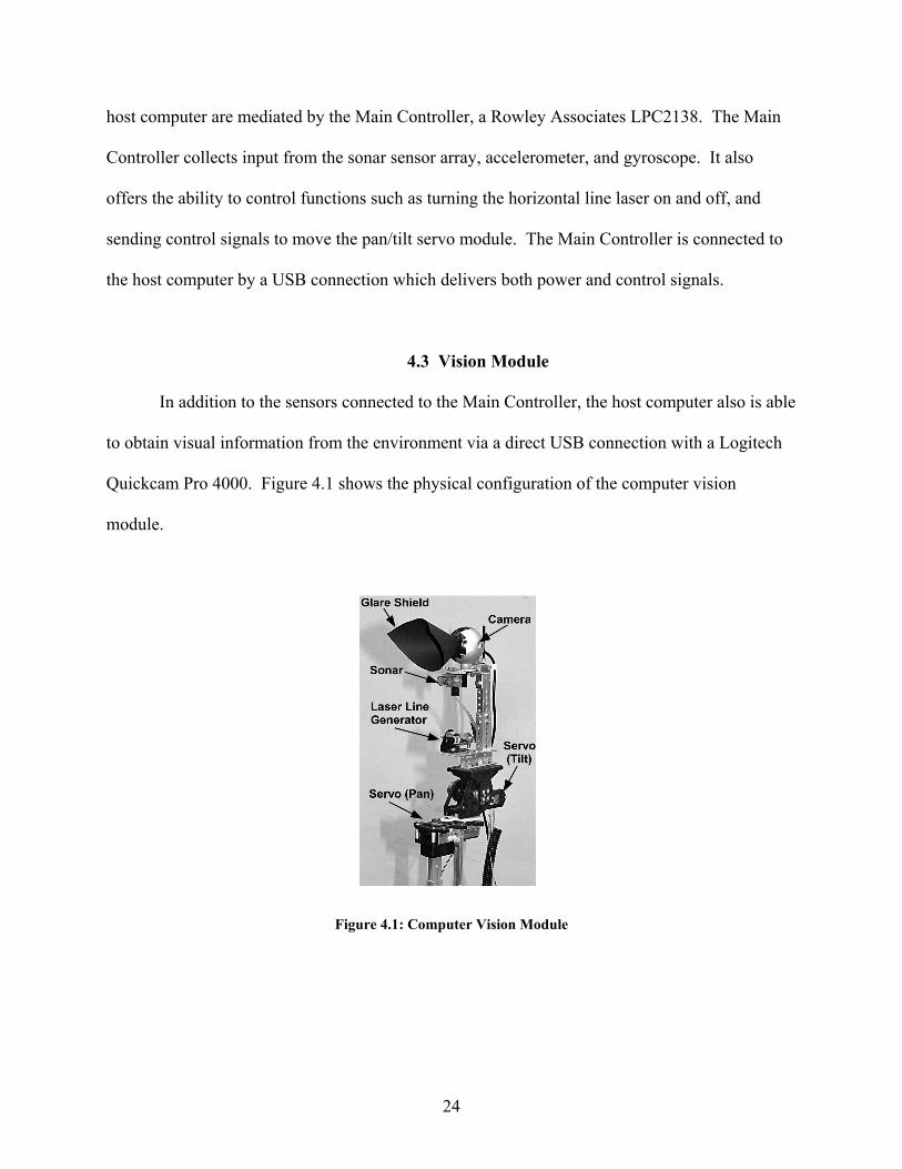
The horizontal line merging was more difficult. Due to the much wider range of segment
slopes, the conditions for merger become complex. The horizontal merging algorithm is based
on the vertical merging technique, but additionally takes into account the slope to limit merge
candidates, and a top to bottom, left to right sorting of line candidates. Images in Figures 4.9
through 4.12 illustrate the operations of the line merging algorithm.
Figure 4.9: Set of all detected Horizontal Lines
34
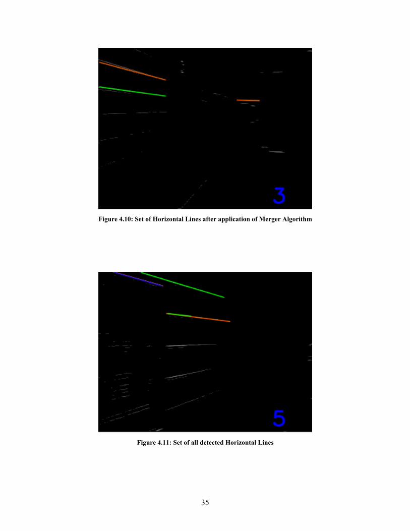
Figure 4.10: Set of Horizontal Lines after application of Merger Algorithm
Figure 4.11: Set of all detected Horizontal Lines
35

Figure 4.12: Improper merge of horizontal lines
The horizontal merge improved line segment quality in most situations, but led to some
improper joins in certain conditions, such as in Figure 4.12. The results were considered a
sufficient improvement and the errors sufficiently small to still be useful. However for a better
discussion of line segment merging, we would direct the reader to Manuel et al. [1995],
Chmielewski [1995], and Hussien and Sridhar [1993].
4.6.5 Doorway Candidate Classification
A doorway is classified by the matching of a lintel with two supporting doorjambs. This
essentially means a valid combination of two strong vertical lines whose top endpoints lie within
a given Euclidean distance from the corresponding endpoints of a strong horizontal line. The
algorithm is the obvious approach and is therefore not detailed here. The matching algorithm is
36

described succinctly in “A method for recognition and localization of generic objects for indoor
navigation” [Kim and Nevatia 1999]. A classification of a potential doorway will result in the
program storing in memory the start and end points of both left and right jamb, the start and
endpoint of the lintel in terms of image coordinates. A flowchart representing the stages of
software processing is presented in Figure 4.13.
37

Figure 4.13: Flowchart for Doorway Candidate Search
38

CHAPTER 5
RESULTS
5.1 Results
This section describes the method used to quantify the performance and the results of the
performance evaluation. In order to empirically analyze the performance of the doorway search
algorithm the following method was used: the wheelchair system was navigated through the
corridors of Boyd Hall at the University of Georgia and video was recorded by the camera and
saved on the host computer, the stored video sequences were then processed by the doorway
candidate search algorithm which saved sample images from the sequence, the sampled images
were then analyzed by hand in order to quantify performance. The process is described in more
detail below.
The speed of the wheelchair was set to the medium setting, which we felt would represent
the top speed a visually impaired user of the system would be safely able to travel at. The
camera was fixed in a forward facing position because the pan/tilt control system is still under
development. We chose to record the traversal in sections of video rather than a single
continuous file. Doing so made the analysis more manageable by allowing us to analyze the
traversal one section at a time, allowing us to skip to later sections without having to analyze all
preceding footage, as well as the option of focusing on particular sections of corridors.
Therefore on occasion the chair was stopped, the current video was saved, then the recording
was started again and the corridor traversal resumed. Starting from the micro-electronics lab the
wheelchair traversed the entire floor of Boyd Hall acquiring video footage. Approximately 9
39

minutes of video was recorded in 7 files, ranging from 1 to 3 minutes long. The videos include
recordings of a typical corridor navigation (driving in the center of a well lit corridor) in addition
to corner turning, traversing a darkened corridor, and navigation through a double door with a
complex configuration.
The doorway candidate search program processes the images and is capable of saving a
composite image comprised of the original footage from the camera, an image of the detected
horizontal and vertical lines, and an image of the doorways detected in the image. Since the
video was recorded at 15 frames per second, analyzing each of the approximately 8100 images
by hand was infeasible. Therefore we configured the program to save every 5th image, for a total
of three images per second. Three sections of video were chosen as representative samples, and
images were sampled for a period between 35 and 43 seconds in each. The resulting data was 3
groups of processed images, the first containing 118 images, the second 130 images, and the
third 107. Each image was analyzed by hand to quantify the following datum: the number of
doors within range (3 meters), the number of doors out of range, the number of doors in range
that were successfully detected, the number of doors out of range that were successfully detected,
and the number of false positives.
The first image sequence analyzed was of a standard corridor traversal, traveling down
the center of a well lit corridor. The end of the corridor is a complex doorway configuration, by
which we mean the corridor ends with a set of double doors, with a second door visible from
between the set of double doors. In this sequence every visible doorway is detected, for a total of
60 doorway candidates. There were 0 false positives. Figure 5.1 shows a typical doorway
candidate on the left side of the corridor being detected, along with the complex doorway
40

configuration in the background. In Figure 5.2 the complete double door region is detected as a
candidate, as well as the doorway on the left side of the corridor.
Figure 5.1: Typical Doorway Candidate Detection
Figure 5.2: Detection of both double doorway and typical doorway
The second group of analyzed images includes a section of corridor starting past the
elevators, traveling through a darkened corridor region, traversing a corner and continuing
41

straight toward a difficult scene of a reflective glass wall with several rectangular supports of the
same size and shape as the glass doorway in the wall. The analysis of this sequence shows a
total of 58 doorway candidates were detected, all doorways are detected as candidates with only
two doorway candidates as false positives. Figure 5.3 shows a doorway candidate detected on
the right side of the corridor and the difficult glass scene in front. The false positives detected in
this sequence both derive from the same region in the scene depicted in Figure 5.4.
Figure 5.3: Difficult glass scene ahead, successful detection on right
42
Figure 5.4: False Positive – rectangular region detected as doorway candidate
The final group of images is based on a video sequence involving a continuation of the
same difficult scene in sequence two, with the addition of a corner traversal. After the corner
traversal a short straight corridor stretch with a doorway on the left is navigated. A second
corner is traversed to a corridor with three elevators on the right and a doorway at the far end.
The analysis of this sequence shows again that every doorway including the elevators was
detected. There were a total of 60 doorway candidates detected, and four false positives. The
difficult region involving reflective glass surfaces resulted in two additional false positives. A
bulletin board that was detected twice as a doorway candidate is indicated in Figure 5.5.
43

Figure 5.5: Two doorway candidates, bulletin board on right is a false positive
The natural inclination would be to require the door jamb to extend a minimum distance
to the floor. However enforcing that requirement would also eliminate some of the robustness to
partial obstructions of doorjambs, such as when a person is standing or walking thereby
occluding the full length of the jamb. Therefore we have found it more effective to accept
occasional anomalies such as this in the candidate detection phase in order to capture doors in
more difficult situations, and allow the doorway verification behavior to further filter the results.
The region of the corridor containing elevators is shown in Figure 5.6. The elevator is detected
as a doorway candidate, note that this image was acquired during the turning of the corner, which
typically results in more blurred images due to the extra motion.
44

Figure 5.6: Successful detection of elevator as doorway candidate
5.2 Execution time and performance
In the design phase we designated as a critical requirement that the system be able to
operate in real time in a real world indoor environment. The design and implementation of the
software architecture demonstrably meets that goal. On the host computer (a Dell Latitude
D600, 1.8 GHz Pentium processor with 1 GB of RAM) the Door Candidate search is capable of
processing images at an average rate of 49 ms. The workstation where the software was
designed and implemented, an Intel Pentium 4.3 GHz processor with 2 GB of RAM, is capable
of processing images at an average rate of 33 ms. The performance is more than capable of
processing all of the images acquired at the current 15 frames per second, which should allow the
future Doorway Verification behavior ample time to perform the subsequent operations, even at
such a high frame rate.
45

CHAPTER 6
CONCLUSION
6.1 Summary
We have presented motivation for the creation of computer vision capabilities for a semi-
autonomous wheelchair and a description of the problem. Background including prior work for
both wheelchair systems utilizing computer vision as well as prior work in the field of detecting
doorways was detailed. A design was proposed for computer vision capabilities to augment the
sensory system of a semi-autonomous wheelchair system in the process of development at the
University of Georgia. The implementation of a real-time software architecture has been
described. Results were presented which prove the design and software architecture are both
suitable for real-time computer vision techniques, and show very good results for detecting
candidate doorways.
6.2 Future Work
Future work to be done on this project should include calibration of the laser range finder
which involves a point-to-distance correspondence. Further work could also be done to improve
the robustness of the laser detection to various factors such as strong white light and reflective
surfaces. In terms of the overarching semi-autonomous wheelchair system, an integration of the
various software modules should be undertaken to make the system work as a functioning whole.
The designed communication protocols between microcontrollers and host computers will also
need to be implemented to allow the achievement of high level semi-autonomous behavior. In
the realm of doorway detection there is a rich opportunity for gather further information from the
46

47
region surrounding a doorway. For example, after a doorway candidate has been detected and
possibly verified, the region on either side of the door jamb could be searched for signs that
indicate room numbers or other information. By detecting appropriately sized rectilinear regions
containing text, and performing optical character recognition, the information obtained could be
used both to enhance the landmark itself – such as informing the user what floor the wheelchair
is on, as well as valuable information such as an Emergency Exit sign. Further work on the laser
range finder will also allow future research to more accurately classify doorways by providing
distance data, which can then be used to develop projective transformation to ensure the potential
doorframe has all of the correct dimensional attributes. The mobile computing platform with its
wealth of sensing and actuator capabilities provides a very exciting platform for future research.
Hopefully the platform will continue to be used for further research which will one day aid
persons with multiple disabilities to live a richer and more autonomous life.

REFERENCES
Argyros, A., Georgiadis, P., Trahianas, P., Tsakiris, D. (2002) “Semi-autonomous
navigation of a robotic wheelchair.” Journal of Intelligent and Robotic Systems 34: 315-
29.
Borgolte, U., Hoyer, H., Buhler, C., Heck, H., Hoelper, R. (1998) "Architectural concepts
of a semi-autonomous wheelchair." Journal of Intelligent and Robotic Systems, 22:233–
253.
Brooks, R. A. (1986) "A robust layered control system for a Mobile Robot." IEEE
Journal of Robotics and Automation, RA-2(1): 14-23.
Chmielewski L. (1995) "A note on merging line segments with the search space reduced
by a condition based on an ordering." Machine Graphics & Vision, 4(1-2): 29-38.
Ciricelli, G., D'Orazio, T., and Distante, A. ( 2003) "Target recognition by components
for mobile robot navigation." Journal of Experimental and Theoretical Artificial
Intelligence. Vol. 15, No. 3, Jul-Sept, 15(3): 281-297
Davies, E. R. (2004) "Machine Vision: Theory, Algorithms, Practicalities." Morgan
Kaufmann Publishers Inc.
48

Foresti, G. L. (2000) "A Real-Time Hough-Based Method for Segment Detection in
Complex Multisensor Images." Real-Time Imaging, 6: 93-111.
Gomi, T. and Griffith, A. (1998) "Developing intelligent wheelchairs for the
handicapped." In Mittal et al. eds., Assistive technology and AI. LNAI-1458, Berlin:
Springer-Verlag, 150-78.
Hussien, B., Sridhar, B. (1993) "A robust line extraction and matching algorithm", SPIE
Intelligent Robots and Computer Vision XII 2055: 369-380.
Jain, R., Kasturi, R., and Schunck, B. G. (1995) Machine Vision. McGraw-Hill, Inc.
Kim, D and Nevatia, R. (1998) "A method for recognition and localization of generic
objects for indoor navigation." Image and Vision Computing, 16(11):729–743.
Levine, S. P., Bell, D. A., Jaros, L. A., Simpson, R. C., Koren, Y., and Borenstein, J.
(1999) "The NavChair Assistive Wheelchair Navigation System." IEEE Transactions on
Rehabilitation Engineering, 7(4): 443-51.
Manuel J., Tavares, R. S., and Padilha, A. J. "A new approach for merging edge line
segments." 7th Portuguese Conference on Pattern Recognition. 1995. Aveiro, Portugal.
Miller, D.P., and Slack, M. G. (1995) "Design and testing of a low-cost robotic
49
wheelchair prototype." Autonomous Robots, 2: 77-88.
Monasterio, I., Lazkano, E., Rano, I., Sierra, B. (2002) "Learning to traverse doors using
visual information." Mathematics and Computers in Simulation, 60: 347-356.
Munoz-Salinas, R., Aguirre, E., Garcia-Silvente, M., Gonzalez, A. (2004) "Door-
detection using computer vision and fuzzy logic." World Scientific and Engineering
Academy and Society, Transactions on Systems, 10(3): 3047-3052.
Muñoz-Salinas, R. Aguirre, E. and García-Silvente, M. (2006) "Detection of doors
using a genetic visual fuzzy system for mobile robots." Autonomous Robots, 21(2): 123-
141.
Ono, Y., Uchiyama H., Potter W. (2004) "A Mobile Robot for Corridor Navigation: A
Multi-Agent Approach." In the Proceedings of the 42nd Annual ACM Southeast
Conference, pp. 379-384.
Stoeter, S. A., Le Mauff, F., Papanikolopoulos, N. P. "Real-Time Door Detection in
Cluttered Environments." Proceedings of the 2000 IEEE International Symposium on
Intelligent Control. Rio Greece, July 2000.
Snaith, M., Lee, D., Probert, P. (1998) "A low-cost system using sparse vision for
navigation in the urban environment." Image and Vision Computing 16: 225-233.
50

51
Trahanias, P.E., Lourakis, M. I. A., Argyros, S. A., Orphanoudakis, S. C. (1997)
"Navigational support for robotic wheelchair platforms: an approach that combines vision
and range sensors." Proceedings of the 1997 IEEE International Conference on Robotics
and Automation, Albuquerque, NM, 1265-70.
Yanco, H. A., Hazel, A., Peacock, A., Smith, S., Wintermute, H. (1995) "Initial report on
Wheelesley: a robotic wheelchair system." Proceedings of the Workshop on Developing
AI Applications for the Disabled, held at the International Joint Conference on Artificial
Intelligence, Montreal, Canada.
http://www.cs.uml.edu/~holly/papers/ijcai95.pdf
Uchiyama, H. (2008) “Perceptual and Navigational Behaviors for Motorized Wheelchair
Operations.” Master's Thesis, The University of Georgia.
Van Veen, T.M. & Groen, F.C.A. (1981) "Discretization errors in the Hough transform."
Pattern Recognition, 14: 137-145.
Yanco, H. A. (2001) "Development and Testing of a Robotic Wheelchair System for
Outdoor Navigation." Proceedings of the 2001 Conference of the Rehabilitation
Engineering and Assistive Technology Society of North America. RESNA Press.

APPENDIX A
SOURCE CODE FOR DOORWAY CANDIDATE DETECTOR
#ifdef _CH_ #pragma package <opencv> #endif #ifndef _EiC #include <cv.h> #include <highgui.h> #include <stdio.h> #include <math.h> #include <string.h> #include <time.h> #endif CvMemStorage* storage = 0; typedef struct Door { CvPoint* lintel, *leftJamb, *rightJamb; } Door; //IMAGES IplImage* img = 0; IplImage* horz_edges = 0; IplImage* vert_edges = 0; IplImage* vert_edges_16S = 0; IplImage* coloredLines1 = 0; IplImage* coloredLines2 = 0; IplImage* display = 0; //COLORS const CvScalar RED = CV_RGB(255,0,0); const CvScalar GREEN = CV_RGB(0,255,0); const CvScalar BLUE = CV_RGB(0,0,255); const CvScalar YELLOW = CV_RGB(255,255,0); const CvScalar ORANGE = CV_RGB(255,100,0); const CvScalar WHITE = CV_RGB(255,255,255);
52

//array of colors used for display CvScalar myColors[] = {RED,GREEN,BLUE,YELLOW,ORANGE}; const int NUM_COLORS = 5; CvScalar color; char* myVid = "/home/tarver/Videos/Thesis Videos/Video 36.wmv"; char* picsDir = "/home/tarver/Documents/Results Analysis/batch3/"; const char* ext = ".jpg"; int fileCount = 0; int frameCount = 0; const int nFrames = 5; char fileName[50]; bool SAVE_FILES = false; bool stop = true; CvFont font; //Vertical Lines const int v_thresh = 32; const int minVotes = 40; const int minLineLength = 40; const int maxLineGap = 4; const int degree = 1; const int VERT_ENOUGH = 4; const int CORNER_DISTANCE = 13;//11; double theta = degree * CV_PI/180; //Horizontal Lines const int h_thresh = 32; const int h_minVotes = 10;//12 const int h_minLineLength = 15;//20 const int h_maxLineGap = 5; double h_theta = degree * CV_PI/180; //how much y difference is allowed to still be considered horizontal const float HORZ_ENOUGH = 0.75; //Misc stuctures/vars for lines CvSeq* v_lines = 0; CvSeq* h_lines = 0; CvSeq* candidate_lines = 0; CvPoint* line; const int BOT = 0; const int TOP = 1; int lowestTop = -1; const int MIN_VLINE_TOP = 85;
53

//DOORS const int LEFT = 0; const int RIGHT = 1; const int LINTEL = 2; const int JAMB_DISTANCE = 12;//15 //jambs must be this many pixels apart CvSeq* allDoors; //Program control vars int waitTime = 100; int up = 30; int down = -30; /* Sort vertical lines in left-to-right order */ static int v_leftToRightSort( const void* _a, const void* _b, void* userdata ) { CvPoint* line1 = (CvPoint*)_a; CvPoint* line2 = (CvPoint*)_b; return line1[TOP].x - line2[TOP].x; } /* Sort horizontal lines in left-to-right order */ static int h_leftToRightSort( const void* _a, const void* _b, void* userdata ) { CvPoint* line1 = (CvPoint*)_a; CvPoint* line2 = (CvPoint*)_b; return line1[LEFT].x - line2[LEFT].x; } /* Sort lines in top-to-bottom and l-to-r order */ static int topToBottomSort( const void* _a, const void* _b, void* userdata ) { CvPoint* line1 = (CvPoint*)_a; CvPoint* line2 = (CvPoint*)_b; int y_diff = line1[LEFT].y - line2[LEFT].y; int x_diff = line1[LEFT].x - line2[LEFT].x; return y_diff ? y_diff : x_diff; } /* convert integer to character */ char* itoa(int val, int base){ static char buf[32] = {0}; int i = 30; for(; val && i ; --i, val /= base) buf[i] = "0123456789abcdef"[val % base]; return &buf[i+1]; } double getEuclidDistance(CvPoint pt1, CvPoint pt2) {
54

double x_diff, y_diff; x_diff = pt1.x - pt2.x; y_diff = pt1.y - pt2.y; return sqrt( (x_diff*x_diff)+(y_diff*y_diff) ); } bool closeEnough(CvPoint pt1, CvPoint pt2) { return (getEuclidDistance(pt1,pt2) < CORNER_DISTANCE); } float getHorizontalSlope(CvPoint* inLine) { //first get the x diff float slope = abs(inLine[LEFT].x - inLine[RIGHT].x); //computers hate infinity...to avoid extremely high slopes (vert lines) //cheat - extreme slopes will have a small x diff if( slope <= 2 ) return 1000; //otherwise return (y2-y1)/(x2-x1) else return abs(inLine[LEFT].y - inLine[RIGHT].y)/slope; } //paint doors in final image void drawDoors() { coloredLines2 = cvCreateImage(cvGetSize(vert_edges),8,3); cvCvtColor(vert_edges,coloredLines2,CV_GRAY2BGR); CvPoint* PointArray = (CvPoint*)malloc( 4*sizeof(CvPoint) ); Door* tmp; int i; if(!allDoors) return; //for each door extract the 4 points, draw from top two to lowest of bottom 2 for(i=0; i < allDoors->total; i++) { tmp = (Door*)cvGetSeqElem(allDoors,i); PointArray[0] = (tmp->leftJamb[BOT]); PointArray[1] = (tmp->leftJamb[TOP]); PointArray[2] = (tmp->rightJamb[TOP]); PointArray[3] = (tmp->rightJamb[BOT]);
55

if(PointArray[0].y > PointArray[3].y) PointArray[3].y = PointArray[0].y; else PointArray[0].y = PointArray[3].y; cvFillConvexPoly(coloredLines2,PointArray,4,RED,8,0); } } //match jambs to lintel void matchEm() { //if there are no lintels or less than 2 jambs a doorway is not possible if(h_lines->total == 0 || v_lines->total < 2) return; //sort left to right cvSeqSort(h_lines,h_leftToRightSort,0); CvPoint* lintel,*leftLine,*rightLine; int i,j,k,leftIndex = 0; Door *possible_door = new Door; storage = cvCreateMemStorage(0); allDoors = cvCreateSeq(CV_SEQ_ELTYPE_GENERIC, sizeof(CvSeq), sizeof(Door) , storage); cvFree(&storage); for( i = 0; i < h_lines->total; i++ ) { lintel = (CvPoint*)cvGetSeqElem(h_lines,i); for(j = leftIndex; j < v_lines->total; j++) { leftLine = (CvPoint*)cvGetSeqElem(v_lines,j); if( closeEnough(leftLine[TOP],lintel[LEFT]) ) { //check the other lines and try to find a match for(k = j+1; k < v_lines->total; k++) { rightLine = (CvPoint*)cvGetSeqElem(v_lines,k);
56

if( closeEnough(rightLine[TOP],lintel[RIGHT]) ) { //ensure the two vertical lines are far enough apart if(abs(leftLine[TOP].x - rightLine[TOP].x) > JAMB_DISTANCE) { //match possible_door->leftJamb = leftLine; possible_door->rightJamb = rightLine; possible_door->lintel = lintel; cvSeqPush(allDoors, possible_door); break; } } //vertical lines are all to the right of the lintel else if( lintel[RIGHT].x < rightLine[TOP].x) break; } //this lintel has no right match or is matched already break; } //stop searching this vertical line and those to the left else if( leftLine[TOP].x < lintel[LEFT].x ) leftIndex++; else break; } } } void detectHorizontalLines() { //ignore horizontal lines below a minimum height int i_height = MIN_VLINE_TOP; //or top of lowest line, whichever makes the smallest area to search if( i_height > lowestTop && lowestTop > 0) i_height = lowestTop; //set region of interest for search cvSetImageROI(horz_edges,cvRect(0,0,horz_edges->width,i_height)); storage = cvCreateMemStorage(0);
57

candidate_lines = cvHoughLines2(horz_edges, storage, CV_HOUGH_PROBABILISTIC, 1, h_theta, h_minVotes, h_minLineLength, h_maxLineGap); cvFree(&storage); CvPoint tLine; int i = 0; //remove lines that are too vertical for(;i<candidate_lines->total;i++) { line = (CvPoint*)cvGetSeqElem(candidate_lines,i); //if not sufficiently horizontal if( getHorizontalSlope(line) > HORZ_ENOUGH) { cvSeqRemove(candidate_lines,i); i--; } } //make sure left point is westernmost for(i = 0; i < candidate_lines->total; i++) { line = (CvPoint*)cvGetSeqElem(candidate_lines,i); if(line[LEFT].x > line[RIGHT].x) { tLine = line[LEFT]; line[LEFT] = line[RIGHT]; line[RIGHT] = tLine; } } } void detectVerticalLines() { storage = cvCreateMemStorage(0); v_lines = cvHoughLines2(vert_edges, storage, CV_HOUGH_PROBABILISTIC, 1, theta, minVotes, minLineLength, maxLineGap); cvFree(&storage); int i; CvPoint top,bot; //remove non-vertical lines //make the bottom point the 0th element (swap top and bot if needed)
58

for(i = 0; i < v_lines->total; i++) { line = (CvPoint*)cvGetSeqElem(v_lines,i); bot = line[0]; top = line[1]; //if top and bottom aren't within D pixels of same column if( abs(top.x - bot.x) > VERT_ENOUGH ) { cvSeqRemove(v_lines,i); i--; } //otherwise flip top and bottom if necessary else { if(top.y > bot.y) { line[0] = top; line[1] = bot; } } } } //only merging subset - the sufficiently horizontal ones void mergeHorizontalLines() { //if less than 2 lines don't attempt to merge, just copy candidates into h_lines if(candidate_lines->total < 2) { storage = cvCreateMemStorage(0); h_lines = cvCloneSeq(candidate_lines,storage); cvFree(&storage); return; } storage = cvCreateMemStorage(0); h_lines = cvCloneSeq(candidate_lines,storage); cvFree(&storage); int i = 0; //sort horizontal lines from top to bottome cvSeqSort(h_lines, topToBottomSort, 0); int HGAP = 5;
59

int VGAP = 4; CvPoint* curLine,*prevLine; for( i = 1; i < h_lines->total; i++) { //get the first line prevLine = (CvPoint*)cvGetSeqElem(h_lines,i-1); curLine = (CvPoint*)cvGetSeqElem(h_lines,i); //same group //TODO consider: might want to user center Y for each...or slopes if( abs(curLine[LEFT].y - prevLine[LEFT].y) <= VGAP ) { //top line is rightmost //A if(prevLine[RIGHT].x > curLine[RIGHT].x) { //A1 //top line dominates bottom if( curLine[LEFT].x >= prevLine[LEFT].x ) { cvSeqRemove(h_lines,i); i--; } //A2 //merge lines else if( (prevLine[LEFT].x - curLine[RIGHT].x) <= HGAP ) { prevLine[LEFT].x = curLine[LEFT].x; //maybe undo y's? prevLine[LEFT].y = curLine[LEFT].y; cvSeqRemove(h_lines,i); i--; } } //rightmost points are equal else if(prevLine[RIGHT].x == curLine[RIGHT].x) { //bottom line dominates if( prevLine[LEFT].x > curLine[LEFT].x ) { //delete top line cvSeqRemove(h_lines,i-1); //set previous to current
60

prevLine = curLine; i--; } //top line dominates else { //remove current line cvSeqRemove(h_lines,i); i--; } } //bottom line is rightmost //C else { //C1 //if bottom line dominates if(prevLine[LEFT].x >= curLine[LEFT].x) { cvSeqRemove(h_lines,i-1); prevLine = curLine; i--; } //C2 //if close enough to merge else if( curLine[LEFT].x - prevLine[RIGHT].x <= HGAP ) { curLine[LEFT].x = prevLine[LEFT].x; curLine[LEFT].y = prevLine[LEFT].y; cvSeqRemove(h_lines,i-1); prevLine = curLine; i--; } } } }//done looping } void mergeVerticalLines() { //do nothing if there are less than 2 lines if(v_lines->total < 2) return; lowestTop = -1;
61

//sort lines from left to right cvSeqSort(v_lines, v_leftToRightSort, 0); CvPoint* curLine; CvPoint* prevLine; int i = 1; int HGAP = 2; int VGAP = 7; for( i = 1; i < v_lines->total; i++) { //get the first line prevLine = (CvPoint*)cvGetSeqElem(v_lines,i-1); curLine = (CvPoint*)cvGetSeqElem(v_lines,i); //same group if( abs(curLine[TOP].x - prevLine[TOP].x) <= HGAP ) { //left line is higher if(prevLine[TOP].y < curLine[TOP].y) { //left line dominates right if( curLine[BOT].y <= prevLine[BOT].y ) { //TODO - don't absorb if right has neighbors? cvSeqRemove(v_lines,i); i--; } //merge lines else if( curLine[TOP].y - prevLine[BOT].y <= VGAP ) { prevLine[BOT].y = curLine[BOT].y; //maybe do x's? cvSeqRemove(v_lines,i); i--; } } //tops are equal else if(prevLine[TOP].y == curLine[TOP].y) { //right line dominates if( prevLine[BOT].y < curLine[BOT].y ) { //delete left line cvSeqRemove(v_lines,i-1);
62

//set previous to current prevLine = curLine; i--; } //left line dominates else { //remove current line //TODO - check for neighbors? cvSeqRemove(v_lines,i); i--; } } //right line is higher else { //if right line dominates if(prevLine[BOT].y <= curLine[BOT].y) { cvSeqRemove(v_lines,i-1); prevLine = curLine; i--; } //if close enough to merge else if( prevLine[TOP].y - curLine[BOT].y <= VGAP ) { curLine[BOT].y = prevLine[BOT].y; cvSeqRemove(v_lines,i-1); prevLine = curLine; i--; } } } }//end for loop //do a final check of the merged lines for( i = 0; i < v_lines->total; i++) { curLine = (CvPoint*)cvGetSeqElem(v_lines,i); //remove those whose tops are too low for doorways if(curLine[TOP].y > MIN_VLINE_TOP) { cvSeqRemove(v_lines,i); i--;
63

} //update the lowest top for ROI of horizontalSearch else if(curLine[TOP].y > lowestTop) lowestTop = line[TOP].y; } } //draw detected vertical lines in green in the image coloredLines1 void drawVerticalLines() { coloredLines1 = cvCreateImage(cvGetSize(vert_edges),8,3); cvCvtColor(vert_edges,coloredLines1,CV_GRAY2BGR); int i; for(i = 0; i < v_lines->total; i++) { line = (CvPoint*)cvGetSeqElem(v_lines,i); //draw it cvLine(coloredLines1, cvPoint(line[0].x,line[0].y), cvPoint(line[1].x,line[1].y), GREEN, 1,CV_AA, 0); } cvPutText( coloredLines1, itoa(v_lines->total,10), cvPoint(260,200), &font, GREEN); } //draw detected horizontal lines in blue in the image coloredLines1 void drawHorizontalLines() { //draw merged lines in image if(!coloredLines1) { //reset ROI, was set previously to top 2/3rds of image cvResetImageROI(horz_edges); //create new cute little color image coloredLines1 = cvCreateImage(cvGetSize(horz_edges),8,3); cvCvtColor(horz_edges,coloredLines1,CV_GRAY2BGR); } int i; //draw merged lines for(i = 0; i < h_lines->total; i++) { line = (CvPoint*)cvGetSeqElem(h_lines,i); //draw it
64

cvLine(coloredLines1, cvPoint(line[0].x,line[0].y), cvPoint(line[1].x,line[1].y), BLUE, 1,CV_AA, 0); } //write number of lines found in bottom right corner cvPutText( coloredLines1, itoa(h_lines->total,10), cvPoint(260,230), &font, BLUE); } //initialize edge images void initEdgeImages() { //create greyscale image from original IplImage* grey = cvCreateImage( cvGetSize(img), 8, 1 ); cvCvtColor(img,grey,CV_BGR2GRAY); //create 1/2 sized image for edge detection horz_edges = cvCreateImage( cvSize(grey->width/2, grey->height/2), 8, 1 ); //downsample greyscale image cvPyrDown(grey, horz_edges, IPL_GAUSSIAN_5x5); //make a second image for vertical edges vert_edges_16S = cvCreateImage(cvSize(horz_edges->width, horz_edges->height),IPL_DEPTH_16S,1); vert_edges = cvCloneImage(horz_edges); cvReleaseImage(&grey); } //prepare image for display void makeDisplayImage() { //make display image, big enough for original plus 1/2 size width display = cvCreateImage(cvSize(640+320,480), IPL_DEPTH_8U, 3 ); //set roi and copy original to top left cvSetImageROI(display,cvRect(0,0,640,480)); cvCopy(img,display); //set roi for upper right corner cvSetImageROI(display,cvRect(640,0,320,240)); IplImage* tmpEdges = 0; if(coloredLines1)
65
cvCopy(coloredLines1,display); else { //make a temporary color image for edges tmpEdges = cvCreateImage(cvGetSize(vert_edges),8,3); //copy vertical edges into temp cvCvtColor(vert_edges,tmpEdges,CV_GRAY2RGB); cvCopy(tmpEdges,display); } //set roi and copy coloredLines1 (currently merged horizontal lines) cvSetImageROI(display,cvRect(640,240,320,240)); if(coloredLines2) cvCopy(coloredLines2,display); else { //make a temporary color image for edges tmpEdges = cvCreateImage(cvGetSize(vert_edges),8,3); //copy vertical edges into temp cvCvtColor(vert_edges,tmpEdges,CV_GRAY2RGB); cvCopy(tmpEdges,display); } cvResetImageROI(display); cvLine(display,cvPoint(640,0),cvPoint(640,480),RED,1,8); cvLine(display,cvPoint(640,240),cvPoint(640+320,240),RED,1,8); if(tmpEdges) cvReleaseImage(&tmpEdges); } //show image on screen void showImage(char* name, IplImage* inImg ) { if(inImg) { IplImage* copy = cvCloneImage(inImg); cvShowImage(name, copy); cvReleaseImage(©); } }
66

void detectVerticalEdges() { //laplace to detect vert edges cvLaplace(horz_edges,vert_edges_16S,3); //scale back down cvConvertScale(vert_edges_16S, vert_edges,1,0); cvReleaseImage(&vert_edges_16S); //threshold to remove weak edge points cvThreshold(vert_edges,vert_edges,v_thresh,255,CV_THRESH_TOZERO); } void detectHorizontalEdges() { //2nd order sobel for horz lines cvSobel(horz_edges,horz_edges,0,2,3); //threshold to remove weak edge points cvThreshold(horz_edges,horz_edges,h_thresh,255,CV_THRESH_TOZERO); } void setupWindows() { // create window cvNamedWindow( "Door Detection", 1 ); //place it cvMoveWindow("Door Detection",0,0); } void adjustSpeed(int num) { if ( waitTime + num > 0 ) waitTime += num; else waitTime = 1; } void initialize() { cvInitFont( &font, CV_FONT_HERSHEY_SIMPLEX, 1,1,0,2,CV_AA); } int main( int argc, char** argv ) {
67
//double time_sum = 0.0; initialize(); setupWindows(); //VIDEO CvCapture* capture = 0; char* filename = argc == 2 ? argv[1] : myVid; capture = cvCaptureFromAVI( filename ); //capture = cvCaptureFromCAM( argc == 2 ? argv[1][0] - '0' : 0 ); if( !capture ) { fprintf(stderr,"Could not initialize capturing...\n"); return -1; } //live video cvSetCaptureProperty(capture,CV_CAP_PROP_FRAME_WIDTH, 640); cvSetCaptureProperty(capture,CV_CAP_PROP_FRAME_HEIGHT, 480); char keyPressed; //VIDEO LOOP for(;;) { //clock_t start = clock(); img = cvQueryFrame(capture); if(!img) break; initEdgeImages(); detectVerticalEdges(); detectVerticalLines(); mergeVerticalLines(); drawVerticalLines(); if(v_lines->total >= 2 ) { detectHorizontalEdges(); detectHorizontalLines(); mergeHorizontalLines();
68

drawHorizontalLines(); matchEm(); drawDoors(); } //time_sum += ((double)clock() - start) / CLOCKS_PER_SEC; //printf("Time elapsed: %f\n", ((double)clock() - start) / CLOCKS_PER_SEC); makeDisplayImage(); showImage("Door Detection",display); frameCount++; char* tmp; if(fileCount < 10) tmp = "000"; else if(fileCount < 100) tmp = "00"; else if(fileCount < 1000) tmp = "0"; else tmp = ""; if( SAVE_FILES && frameCount % nFrames == 0 ) { sprintf(fileName,"%s%s%d%s",picsDir,tmp,fileCount,ext); cvSaveImage(fileName,display); fileCount++; } //clean up structures in memory cvClearSeq(allDoors); cvClearSeq(candidate_lines); cvClearSeq(v_lines); cvClearSeq(h_lines); //interactive program control if(stop) { keyPressed = cvWaitKey(1000000); if(keyPressed != -1)
69

{ if(keyPressed == 'q') break; //- else if(keyPressed == -85) adjustSpeed(down); //+ else if(keyPressed == -83) adjustSpeed(up); else if(keyPressed == '.') {;} else if(keyPressed == 'g' ) { sprintf(fileName,"%s%s%d%s",picsDir,tmp,fileCount,ext); cvSaveImage(fileName,display); fileCount++; } else if(keyPressed == 's' ) { SAVE_FILES = true; } else if(keyPressed == 'e' ) { SAVE_FILES = false; } else stop = false; } } else { keyPressed = cvWaitKey(waitTime); if(keyPressed != -1) { if(keyPressed == 'q' ) break; else if(keyPressed == -85) adjustSpeed(down); else if(keyPressed == -83) adjustSpeed(up); else if(keyPressed == 'g' ) {
70

sprintf(fileName,"%s%s%d%s",picsDir,tmp,fileCount,ext); cvSaveImage(fileName,display); fileCount++; } else if(keyPressed == 's' ) { SAVE_FILES = true; } else if(keyPressed == 'e' ) { SAVE_FILES = false; } else stop = true; } } //release all images cvReleaseImage( &horz_edges ); cvReleaseImage( &vert_edges ); cvReleaseImage( &coloredLines1 ); cvReleaseImage( &coloredLines2 ); cvReleaseImage( &display ); } //printf("Avg time: %f\n",time_sum/frameCount); //VIDEO CLEANUP cvReleaseCapture( &capture ); cvDestroyAllWindows(); // release both images cvReleaseImage( &horz_edges ); cvReleaseImage( &vert_edges ); cvReleaseImage( &coloredLines1 ); cvReleaseImage( &coloredLines2 ); cvReleaseImage( &display ); return 0; } #ifdef _EiC main(1,"DoorDetector.c"); #endif
71

72

APPENDIX B
OPENCV FUNCTION REFERENCE
PyrDown Downsamples image void cvPyrDown( const CvArr* src, CvArr* dst, int filter=CV_GAUSSIAN_5x5 );
src The source image.
dst The destination image, should have 2x smaller width and height than the source.
filter Type of the filter used for convolution; only CV_GAUSSIAN_5x5 is currently supported.
The function cvPyrDown performs downsampling step of Gaussian pyramid decomposition. First it convolves source image with the specified filter and then downsamples the image by rejecting even rows and columns.
CvtColor Converts image from one color space to another void cvCvtColor( const CvArr* src, CvArr* dst, int code );
src The source 8-bit (8u), 16-bit (16u) or single-precision floating-point (32f) image.
dst The destination image of the same data type as the source one. The number of channels may be different.
code Color conversion operation that can be specifed using CV_<src_color_space>2<dst_color_space> constants (see below).
The function cvCvtColor converts input image from one color space to another. The function ignores colorModel and channelSeq fields of IplImage header, so the source image color space should be specified correctly (including order of the channels in case of RGB space, e.g. BGR means 24-bit format with B0 G0 R0 B1 G1 R1 ... layout, whereas RGB means 24-bit format with R0 G0 B0 R1 G1 B1 ... layout).
73

Sobel Calculates first, second, third or mixed image derivatives using extended Sobel operator void cvSobel( const CvArr* src, CvArr* dst, int xorder, int yorder, int aperture_size=3 );
src Source image.
dst Destination image.
xorder Order of the derivative x .
yorder Order of the derivative y .
aperture_size Size of the extended Sobel kernel, must be 1, 3, 5 or 7. In all cases except 1, aperture_size ×aperture_size separable kernel will be used to calculate the derivative. For aperture_size=1 3x1 or 1x3 kernel is used (Gaussian smoothing is not done). There is also special value CV_SCHARR (=-1) that corresponds to 3x3 Scharr filter that may give more accurate results than 3x3 Sobel. Scharr aperture is:
| -3 0 3| |-10 0 10| | -3 0 3|
for x-derivative or transposed for y-derivative.
The function cvSobel calculates the image derivative by convolving the image with the appropriate kernel: dst(x,y) = dxorder+yodersrc/dxxorder•dyyorder |(x,y)
The Sobel operators combine Gaussian smoothing and differentiation so the result is more or less robust to the noise. Most often, the function is called with (xorder=1, yorder=0, aperture_size=3) or (xorder=0, yorder=1, aperture_size=3) to calculate first x- or y- image derivative. The first case corresponds to |-1 0 1| |-2 0 2| |-1 0 1|
kernel and the second one corresponds to |-1 -2 -1| | 0 0 0| | 1 2 1| or | 1 2 1| | 0 0 0| |-1 -2 -1|
74

kernel, depending on the image origin (origin field of IplImage structure). No scaling is done, so the destination image usually has larger by absolute value numbers than the source image. To avoid overflow, the function requires 16-bit destination image if the source image is 8-bit. The result can be converted back to 8-bit using cvConvertScale or cvConvertScaleAbs functions. Besides 8-bit images the function can process 32-bit floating-point images. Both source and destination must be single-channel images of equal size or ROI size.
Laplace Calculates Laplacian of the image void cvLaplace( const CvArr* src, CvArr* dst, int aperture_size=3 );
src Source image.
dst Destination image.
aperture_size Aperture size (it has the same meaning as in cvSobel).
The function cvLaplace calculates Laplacian of the source image by summing second x- and y- derivatives calculated using Sobel operator: dst(x,y) = d2src/dx2 + d2src/dy2
Specifying aperture_size=1 gives the fastest variant that is equal to convolving the image with the following kernel: |0 1 0| |1 -4 1| |0 1 0|
Similar to cvSobel function, no scaling is done and the same combinations of input and output formats are supported.
HoughLines2 Finds lines in binary image using Hough transform CvSeq* cvHoughLines2( CvArr* image, void* line_storage, int method, double rho, double theta, int threshold, double param1=0, double param2=0 );
image The input 8-bit single-channel binary image. In case of probabilistic method the image is modified by the function.
line_storage The storage for the lines detected. It can be a memory storage (in this case a sequence of
75

lines is created in the storage and returned by the function) or single row/single column matrix (CvMat*) of a particular type (see below) to which the lines' parameters are written. The matrix header is modified by the function so its cols or rows will contain a number of lines detected. If line_storage is a matrix and the actual number of lines exceeds the matrix size, the maximum possible number of lines is returned (in case of standard hough transform the lines are sorted by the accumulator value).
method The Hough transform variant, one of:
• CV_HOUGH_STANDARD - classical or standard Hough transform. Every line is represented by two floating-point numbers (ρ, θ), where ρ is a distance between (0,0) point and the line, and θ is the angle between x-axis and the normal to the line. Thus, the matrix must be (the created sequence will be) of CV_32FC2 type.
• CV_HOUGH_PROBABILISTIC - probabilistic Hough transform (more efficient in case if picture contains a few long linear segments). It returns line segments rather than the whole lines. Every segment is represented by starting and ending points, and the matrix must be (the created sequence will be) of CV_32SC4 type.
• CV_HOUGH_MULTI_SCALE - multi-scale variant of classical Hough transform. The lines are encoded the same way as in CV_HOUGH_STANDARD.
rho Distance resolution in pixel-related units.
theta Angle resolution measured in radians.
threshold Threshold parameter. A line is returned by the function if the corresponding accumulator value is greater than threshold.
param1 The first method-dependent parameter:
• For classical Hough transform it is not used (0). • For probabilistic Hough transform it is the minimum line length. • For multi-scale Hough transform it is divisor for distance resolution rho. (The
coarse distance resolution will be rho and the accurate resolution will be (rho / param1)).
param2 The second method-dependent parameter:
• For classical Hough transform it is not used (0). • For probabilistic Hough transform it is the maximum gap between line segments
lieing on the same line to treat them as the single line segment (i.e. to join them). • For multi-scale Hough transform it is divisor for angle resolution theta. (The
coarse angle resolution will be theta and the accurate resolution will be (theta / param2)).
The function cvHoughLines2 implements a few variants of Hough transform for line detection.
76

Threshold Applies fixed-level threshold to array elements void cvThreshold( const CvArr* src, CvArr* dst, double threshold, double max_value, int threshold_type );
src Source array (single-channel, 8-bit of 32-bit floating point).
dst Destination array; must be either the same type as src or 8-bit.
threshold Threshold value.
max_value Maximum value to use with CV_THRESH_BINARY and CV_THRESH_BINARY_INV thresholding types.
threshold_type Thresholding type (see the discussion)
The function cvThreshold applies fixed-level thresholding to single-channel array. The function is typically used to get bi-level (binary) image out of grayscale image (cvCmpS could be also used for this purpose) or for removing a noise, i.e. filtering out pixels with too small or too large values. There are several types of thresholding the function supports that are determined by threshold_type: threshold_type=CV_THRESH_BINARY: dst(x,y) = max_value, if src(x,y)>threshold 0, otherwise threshold_type=CV_THRESH_BINARY_INV: dst(x,y) = 0, if src(x,y)>threshold max_value, otherwise threshold_type=CV_THRESH_TRUNC: dst(x,y) = threshold, if src(x,y)>threshold src(x,y), otherwise threshold_type=CV_THRESH_TOZERO: dst(x,y) = src(x,y), if src(x,y)>threshold 0, otherwise threshold_type=CV_THRESH_TOZERO_INV: dst(x,y) = 0, if src(x,y)>threshold src(x,y), otherwise
And this is the visual description of thresholding types:
77

78