COMPUTER NETWORKS UNIT - 5. 2 Communication takes place between processes or application programs by...
39
COMPUTER NETWORKS UNIT - 5
-
Upload
prince-palmer -
Category
Documents
-
view
215 -
download
2
Transcript of COMPUTER NETWORKS UNIT - 5. 2 Communication takes place between processes or application programs by...

COMPUTER NETWORKS
UNIT - 5

2
• Communication takes place between processes or application programs by using port addresses
• TCP is a connection-oriented protocol• Does not mean it has a physical connection between sender and receiver• TCP provides the function to allow a connection virtually exists – also called
virtual circuit• TCP provides the functions:
• Dividing a chunk of data into segments• Reassembly segments into the original chunk• Provide further the functions such as reordering and data resend
• Offering a reliable byte-stream delivery service
TCP – Transmission Control Protocol

3
1 2 3
Sender
TimeoutretransmitA1 A3
1 3
Recipient
2
A2

4
• A Typical Procedure• Sender
• TCP divides a message into segments• Add sequence no.• Send the segments in sequence and wait for acknowledgement• If an acknowledgement for a segment is not received for a certain
period of time, resend it until an acknowledgement is received• Recipient
• When receiving segments, send the acknowledgement with correct number
• Reassembly the segments back to the message

5
Source Port Destination Port
Sequence Number
Acknowledgement Number
Checksum
Message Data
TCP
Dividing and Reassembly
Message

The TCP datagram format
TCP Datagram

TCP Datagram A brief explanation of the functions of different fields are given below: Source port (16 bits): It defines the port number of the application program in the host of the sender Destination port (16 bits): It defines the port number of the application program in the host of the receiver Sequence number (32 bits): It conveys the receiving host which octet in this sequence comprises the first byte in the segment Acknowledgement number (32 bits): This specifies the sequence number of the next octet that receiver expects to receive HLEN (4 bits): This field specifies the number of 32-bit words present in the TCP header Control flag bits (6 bits): URG: Urgent pointer ACK: Indicates whether acknowledge field is valid PSH: Push the data without buffering RST: Resent the connection SYN: Synchronize sequence numbers during connection establishment FIN: Terminate the connection Window (16 bits): Specifies the size of window Checksum (16 bits): Checksum used for error detection. User pointer (16 bits): Used only when URG flag is valid Options: Optional 40 bytes of information

Port Numbers Transport layer address is specified with the help a 16-bit Port number in the range of 0 and 65535. Internet Assigned Number Authority (IANA) has divided the addresses in three ranges:
Well-known ports: The ports in the range from 0 to 1023 are assigned and controlled by IANA. These port numbers are commonly used as universal port numbers in the servers for the convenience of many clients the servers serve.
Registered ports: Registered ports in the range from 1024 to 49151 are not assigned or controlled by IANA. However, they can only be registered with IANA to avoid duplication.
Dynamic ports: Dynamic ports (49152 to 65535) are neither controlled by IANA nor need to be registered. They can be defined at the client site and chosen randomly by the transport layer software.

9
• A computer may perform a number of network applications at the same time
• FTP + SMTP + HTTP, etc.• Each computer has only one network address, how
can it serve so many applications at the same time?
Port Multiplexing
by port multiplexing
Network add:158.132.161.99
Port 21 Port 25
Port 80
FTP SMTP
HTTP

10
Well-known Port Numbers
• Some port numbers are reserved for some purposes• Port 21: FTP – file transfer• Port 25: SMTP – mail transfer• Port 23: TELNET – remote login• Port 80: HTTP – Web access
• These port numbers are well known to all computers in the network
• E.g. whenever a client access port 25 of the server, it means the client needs SMTP service

The three types of addresses used in TCP/IP are shown in Fig. TCP establishes a virtual path between the source and destination processes before any data communication by using two procedures, connection establishment to start reliably and connection termination to terminate gracefully,
Three types of addresses used in TCP/IP

Connection-oriented service TCP performs data communication in full-duplex mode, that is both the sender and receiver processes can send segments simultaneously. For connection establishment in full-duplex mode, a four-way protocol can be used. However, the second and third steps can be combined to form a three-way handshaking protocol with the following three steps . Step 1: The client sends SYN segment, which includes, source and destination port numbers, and an initialization sequence number (ISN), which is essentially the byte number to be sent from the client to the server.
Step 2: The server sends a segment, which is a two-in-one segment. It acknowledges the receipt of the previous segment and it also acts as initialization segment for the server.
Step3: The client sends an ACK segment, which acknowledges the receipt of the second segment

Protocol for connection establishment

Similarly for connection termination, a four-way handshaking protocol is necessary for termination of connection in both directions as shown in Fig. The four steps are as follows: Step 1: The client sends a FIN segment to the server.
Step 2: The server sends an ACK segment indicating the receipt of the FIN segment and the segment also acts as initialization segment for the server.
Step3: The server can still continue to send data and when the data transfer is complete it sends a FIN segment to the client.
Step4: The client sends an ACK segment, which acknowledges the receipt of the FIN segment sent by the server.

Protocol for connection termination

Reliable Communication in TCP
Flow control: Flow control refers to a set of procedures used to restrict the amount of data that the sender can send before waiting for acknowledgement.As incoming data must be checked and processed before they can be used , The rate of such processing is often slower than than the rate of transmission. Thus each receiving device has a block of memory, called a buffer, reserved for storing incoming data until they are processed.an send acknowledgement any time.

TCP uses byte-oriented sliding window protocol, which allows efficient transmission of data and at the same time the destination host is not overwhelmed with data. The flow control operation is in Fig. As shown in the figure, the receiver has a buffer size of 8 Kbytes. After receiving 4 K bytes, the window size is reduced to 4 Kbytes. After receiving another 3 K bytes, the window size reduces to 1 K bytes. After the buffer gets empty by 4 K bytes, the widow size increases to 7 K bytes. So it may be noted that the window size is totally controlled by the receiver window size, which can be increased or decreased dynamically by the destination. The destination host can send acknowledgement any time.

Figure : Flow control in TCP

Error Control: Error control is both error detection and error correction
Error control in TCP includes mechanism for detecting corrupted segments with the help of checksum field. Acknowledgement method is used to confirm the receipt of uncorrupted data. If the acknowledgement is not received before the time-out, it is assumed that the data or the acknowledgement has been corrupted or lost. It may be noted that there is no negative acknowledgement in TCP.

Error detection and correction in TCP is achieved through the use of three simple three tools: ---checksum-acknowledgement -time-out.

User Datagram protocol (UDP) UDP is responsible for differentiating among multiple source and destination processes within one host. Multiplexing and demultiplexing operations are performed using the port mechanism.
Multiplexing and demultiplexing mechanism of UDP

UDP Datagram

The UDP datagram format is shown in Fig. A brief description of different fields of the datagram are given below: Source port (16 bits): It defines the port number of the application program in the host of the sender Destination port (16 bits): It defines the port number of the application program in the host of the receiver Length: It provides a count of octets in the UDP datagram, minimum length = 8 Checksum: It is optional, 0 in case it is not in use

Characteristics of the UDP Key characteristics of UDP are given below: •UDP provides an unreliable connectionless delivery service using IP to transport messages between two processes •UDP messages can be lost, duplicated, delayed and can be delivered out of order •UDP is a thin protocol, which does not add significantly to the functionality of IP •It cannot provide reliable stream transport service
The above limitations can be overcome by using connection-oriented transport layer protocol known as Transmission Control Protocol (TCP).

25
• Application layer protocols define the rules when implementing specific network applications
• Rely on the underlying layers to provide accurate and efficient data delivery
• Typical protocols:• FTP – File Transfer Protocol
• For file transfer• Telnet – Remote terminal protocol
• For remote login on any other computer on the network• SMTP – Simple Mail Transfer Protocol
• For mail transfer• HTTP – Hypertext Transfer Protocol
• For Web browsing

26
SMTP
TCP
IP, ARP, ICMP
Network Interface
SMTP
TCP
IP, ARP, ICMP
Network Interface
SMTP ServerClient
Actual
Virtual
Example: SMTP

27
• The underlying layers have guaranteed accurate data delivery
• We need to make a lot agreements with the server in application layer before sending mail
1. Agree on how data is represented• Binary or ASCII
2. Ensure the right recipient• There may be 1000 users served by the server
3. Ensure the client has the right to send mail• Some clients are not welcome

SMTP MODEL - Procedure
• The SMTP design is based on the following model of communication: as the result of a user mail request, the sender-SMTP establishes a two-way transmission channel to a receiver-SMTP.
• The receiver-SMTP may be either the ultimate destination or an intermediate.
• SMTP commands are generated by the sender-SMTP and sent to the receiver-SMTP. SMTP replies are sent from the receiver-SMTP to the sender-SMTP in response to the
commands.
28

29
Mail message formatRFC(Request for Comment) 822:
standard for text message format:
• header lines, e.g.,– To:– From:– Subject:different from SMTP commands!
• body– the “message”, ASCII characters
only. – OK for text messages
header
body
blankline
• What about sending a jpeg image, which is not ASCII– Encode it to 7-bit ASCII– How does the receiver know that the message is a jpeg image?
Need additional headers called the Multipurpose Internet Mail Extension (MIME) headers

Multipurpose Internet Mail Extensions (MIME) is an Internet standard that extends the format of email (RFC 822 Standard) to support:
Text in character sets other than ASCIINon-text attachmentsMessage bodies with multiple partsHeader information in non-ASCII character sets
Multipurpose Internet Mail Extensions

31
MIME typesContent-Type: type/subtype; parameters
Text• example subtypes: plain,
html
Image• example subtypes: jpeg,
gif
Audio• example subtypes: basic ,
(32 kbps coding)
Video• example subtypes: mpeg,
quicktime
Application• other data that must be
processed by reader before “viewable”
• example subtypes: msword, octet-stream

File Transfer Protocol• FTP works on the client/server principle. A client program enables
the user to interact with a server in order to access information and services on the server computer.
• Files that can be transferred are stored on computers called FTP servers. To access these files, an FTP client program is used. This is an interface that allows the user to locate the file(s) to be transferred and initiate the transfer process.
• Process: To transfer files with FTP, you use a program often called the "client." The FTP client program initiates a connection to a remote computer running FTP "server" software.
• After the connection is established, the client can choose to send and/or receive copies of files, singly or in groups.
• To connect to an FTP server, a client requires a username and password as set by the administrator of the server.

Transfer Files in a Heterogeneous Host Environment
• Due to multiple hardware types and operating systems file are converted to four environmentally neutral data type for transport and the converted to local types at the destination– ASCII A NVT-ASCII– EBCDIC E EBCDIC Text– IMAGE I Raw binary, series of octets– LOCAL L Raw binary using a variable byte size
• Client responsibility to tell server data type to use• Default data type, unless otherwise specified is ASCII
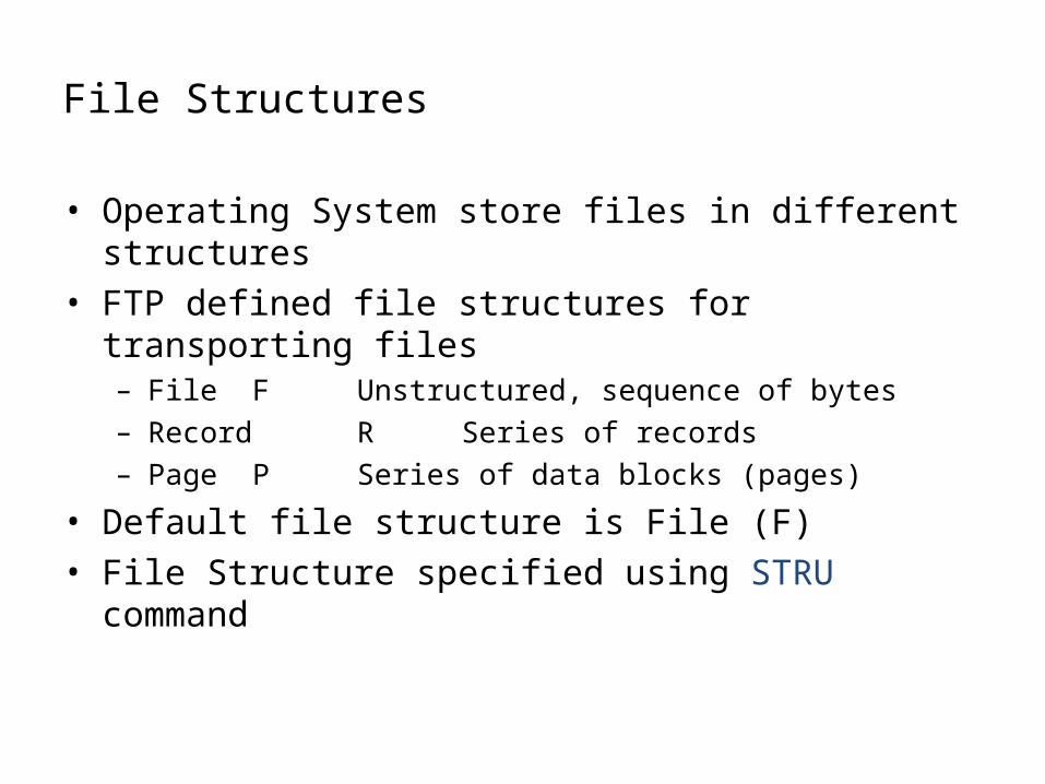
File Structures
• Operating System store files in different structures• FTP defined file structures for transporting files
– File F Unstructured, sequence of bytes– Record R Series of records– Page P Series of data blocks (pages)
• Default file structure is File (F)• File Structure specified using STRU command

Transmission Modes
• Mode is used to specify additional coding or sequencing performed on data
• independent of data type and file structure– Stream S stream of bytes, if record structure
EOF sent as record indication; if file eof indicated by closing stream
– Block B file sent as sequence of blocks preceded by header info allows
restart of an interruped transfer– Compressed C data compressed using run length
encoding
36
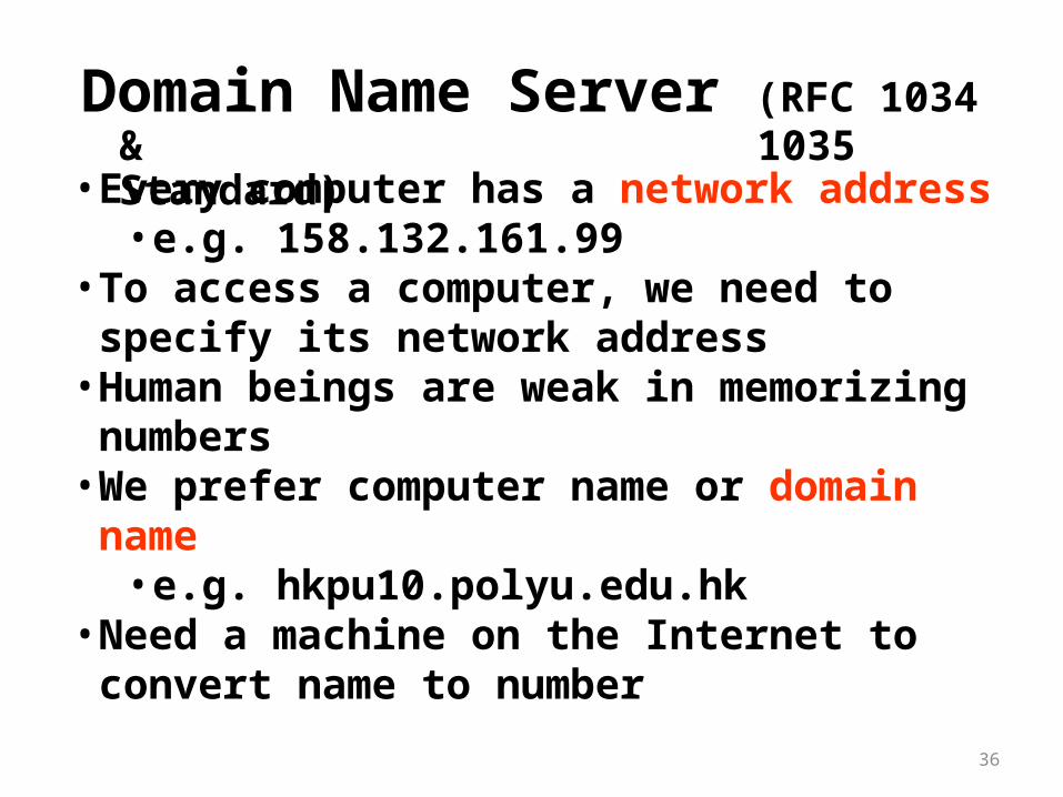
Domain Name Server (RFC 1034 & 1035 Standard)
• Every computer has a network address• e.g. 158.132.161.99
• To access a computer, we need to specify its network address
• Human beings are weak in memorizing numbers• We prefer computer name or domain name
• e.g. hkpu10.polyu.edu.hk• Need a machine on the Internet to convert name to
number

The Domain Name System is basically a distributed database of host information associating many types of information (e.g. IP address, mail exchanger, etc.) with domain names.
DNS's distributed database is indexed by domain names. Each domain name is essentially just a path in a large tree, called the domain name space.
Domain Name : Each node in the tree has a text label (without dots) that can be up to 63 characters long. A null (zero-length) label is reserved for the root. The full domain name of any node in the tree is the sequence of labels on the path from that node to the root. Domain names are always read from the node toward the root ("up" the tree), with dots separating the names in the path.
Each node in the Domain Name Space has a text label (the root node has a special zero-length label, "") and is uniquely identified by its domain name, i.e. the list of the labels on the path from the node to the root, separated by dots

Figure Domain name space

TCP/IP Protocol Suite 39
Figure 19.3 Domain names and labels