Computer Networks Set 7 Multiplexing. FDM TDM Statistical TDM CDM Example: DSL.
30
Computer Networks Set 7 Multiplexing
-
date post
21-Dec-2015 -
Category
Documents
-
view
249 -
download
1
Transcript of Computer Networks Set 7 Multiplexing. FDM TDM Statistical TDM CDM Example: DSL.
Computer Networks
Set 7Multiplexing
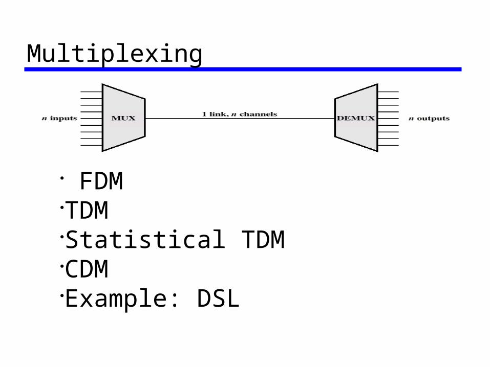
Multiplexing
FDMTDMStatistical TDMCDMExample: DSL
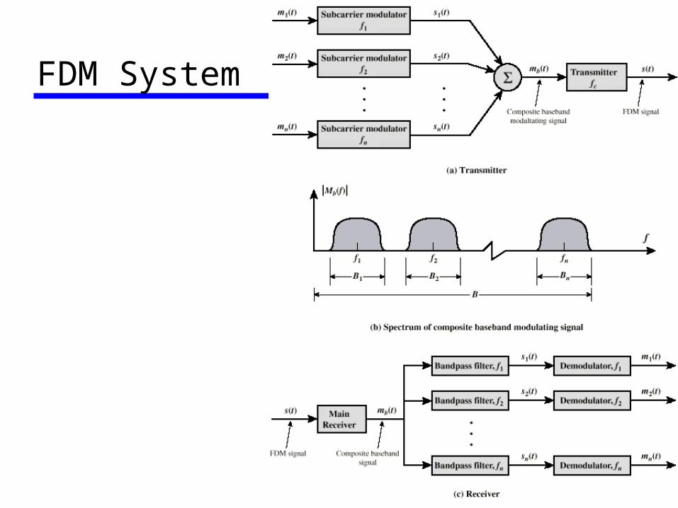
FDM System
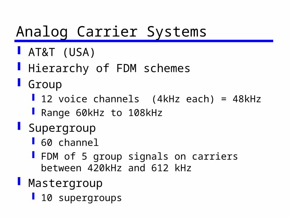
Analog Carrier Systems AT&T (USA) Hierarchy of FDM schemes Group
12 voice channels (4kHz each) = 48kHz Range 60kHz to 108kHz
Supergroup 60 channel FDM of 5 group signals on carriers between
420kHz and 612 kHz Mastergroup
10 supergroups
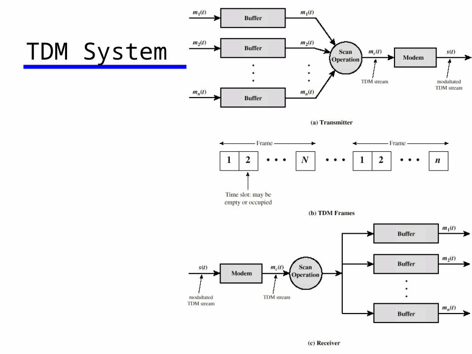
TDM System
TDM Link Control No headers and tailers Data link control protocols not needed Flow control
Data rate of multiplexed line is fixed If one channel receiver can not receive data,
the others must carry on The corresponding source must be quenched This leaves empty slots
Error control Errors are detected and handled by individual
channel systems
Framing No flag or SYNC characters bracketing
TDM frames Must provide synchronizing mechanism Added digit framing
One control bit added to each TDM frame Looks like another channel - control channel
Identifiable bit pattern used on control channel e.g. alternating 01010101unlikely on a data
channel Can compare incoming bit patterns on each
channel with sync pattern
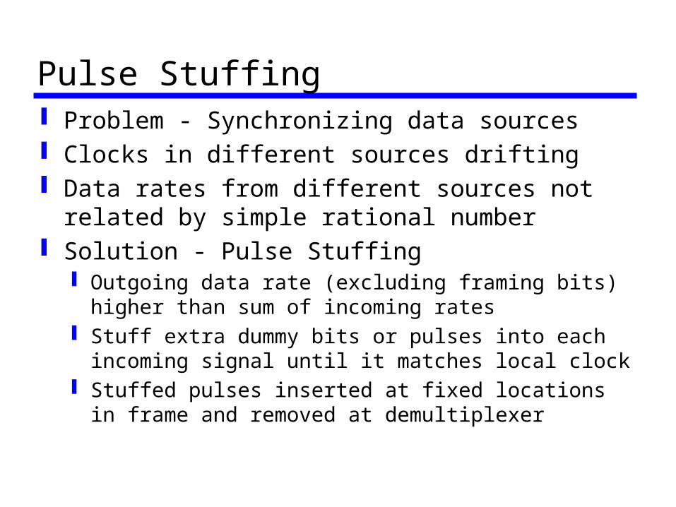
Pulse Stuffing Problem - Synchronizing data sources Clocks in different sources drifting Data rates from different sources not
related by simple rational number Solution - Pulse Stuffing
Outgoing data rate (excluding framing bits) higher than sum of incoming rates
Stuff extra dummy bits or pulses into each incoming signal until it matches local clock
Stuffed pulses inserted at fixed locations in frame and removed at demultiplexer
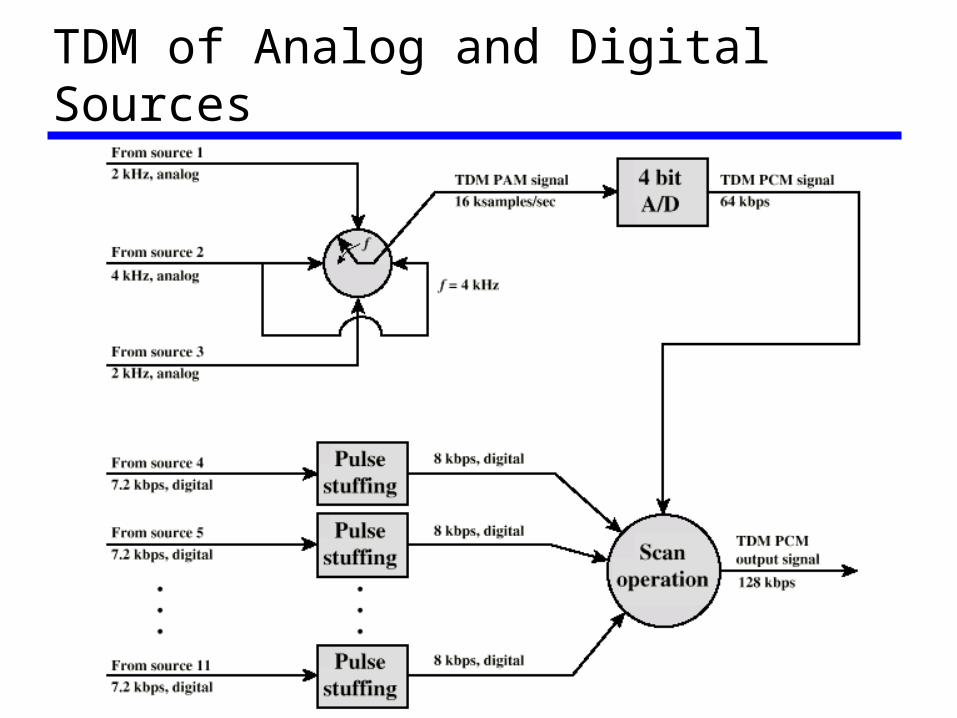
TDM of Analog and Digital Sources
Digital Carrier Systems Hierarchy of TDM USA/Canada/Japan use one system ITU-T use a similar (but different) system US system based on DS-1 format Multiplexes 24 channels Each frame has 8 bits per channel plus
one framing bit 193 bits per frame
Digital Carrier Systems (2) For voice each channel contains one word of
digitized data (PCM, 8000 samples per sec) Data rate 8000x193 = 1.544Mbps Five out of six frames have 8 bit PCM samples Sixth frame is 7 bit PCM word plus signaling bit Signaling bits form stream for each channel
containing control and routing info Same format for digital data
23 channels of data 7 bits per frame plus indicator bit for data or systems
control
24th channel is sync
Mixed Data DS-1 can carry mixed voice and data
signals 24 channels used No sync byte Can also interleave DS-1 channels
Ds-2 is four DS-1 giving 6.312Mbps
ISDN User Network Interface ISDN allows multiplexing of devices over
single ISDN line Two interfaces
Basic ISDN Interface Primary ISDN Interface
Basic ISDN Interface (1) Digital data exchanged between subscriber
and NTE - Full Duplex Separate physical line for each direction Pseudoternary coding scheme
1=no voltage, 0=positive or negative 750mV +/-10%
Data rate 192kbps Basic access is two 64kbps B channels and
one 16kbps D channel This gives 144kbps multiplexed over 192kbps Remaining capacity used for framing and sync
Basic ISDN Interface (2) B channel is basic iser channel Data PCM voice Separate logical 64kbps connections o
different destinations D channel used for control or data
LAPD frames Each frame 48 bits long One frame every 250ms
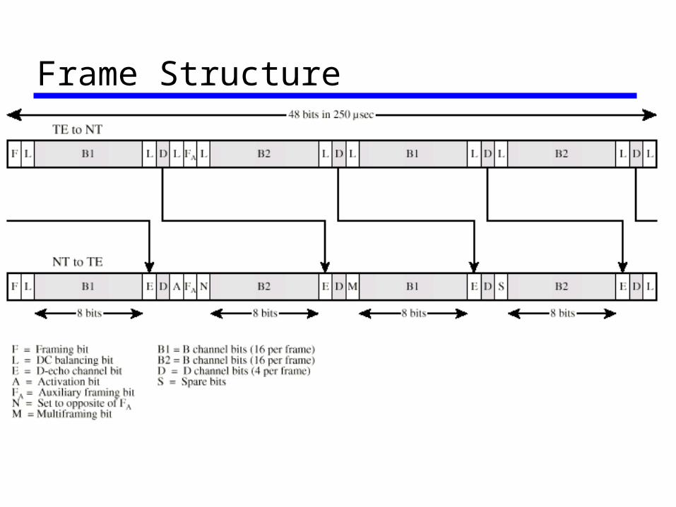
Frame Structure
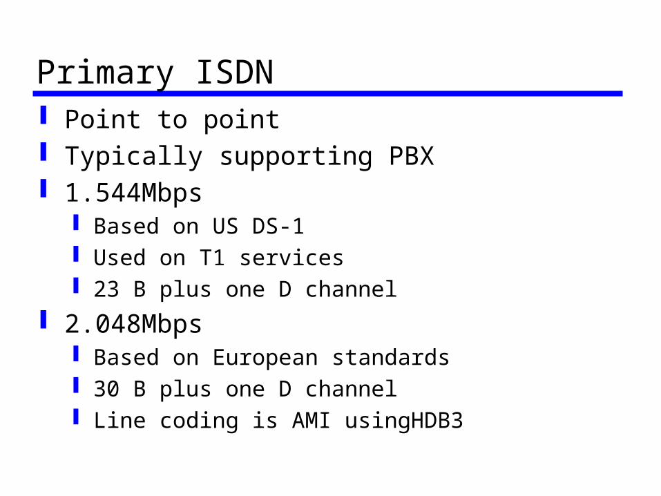
Primary ISDN Point to point Typically supporting PBX 1.544Mbps
Based on US DS-1 Used on T1 services 23 B plus one D channel
2.048Mbps Based on European standards 30 B plus one D channel Line coding is AMI usingHDB3
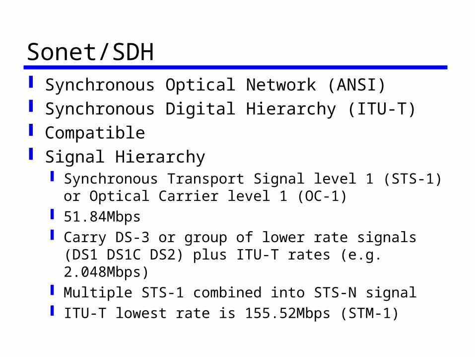
Sonet/SDH Synchronous Optical Network (ANSI) Synchronous Digital Hierarchy (ITU-T) Compatible Signal Hierarchy
Synchronous Transport Signal level 1 (STS-1) or Optical Carrier level 1 (OC-1)
51.84Mbps Carry DS-3 or group of lower rate signals (DS1
DS1C DS2) plus ITU-T rates (e.g. 2.048Mbps) Multiple STS-1 combined into STS-N signal ITU-T lowest rate is 155.52Mbps (STM-1)
Statistical TDM In Synchronous TDM many slots are
wasted Statistical TDM allocates time slots
dynamically based on demand Multiplexer scans input lines and collects
data until frame full Data rate on line lower than aggregate
rates of input lines
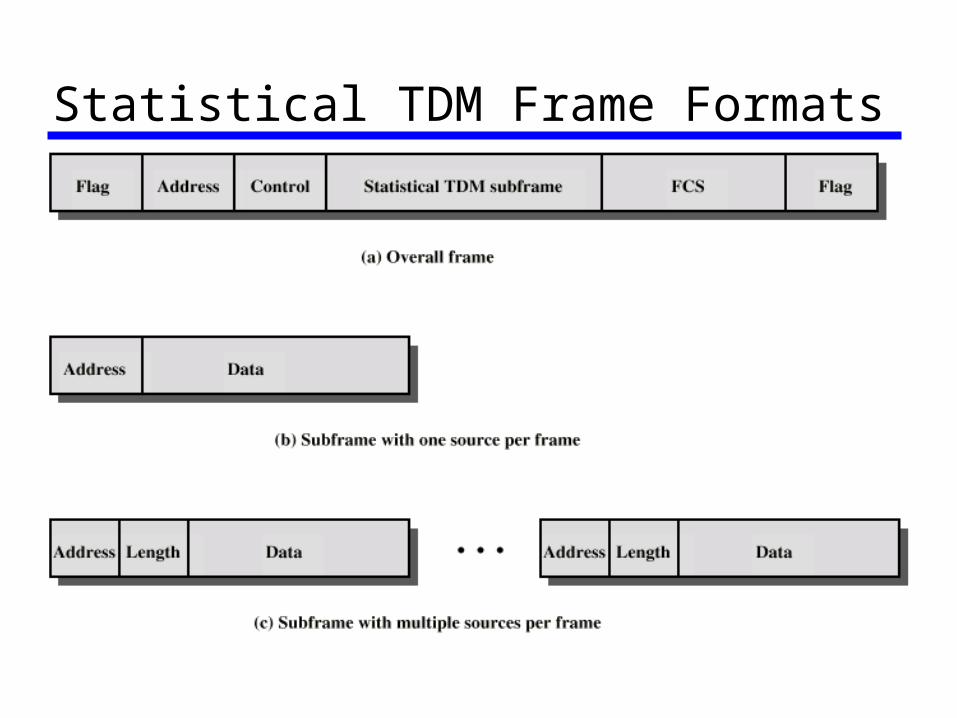
Statistical TDM Frame Formats
Performance Output data rate less than aggregate
input rates May cause problems during peak periods
Buffer inputs Keep buffer size to minimum to reduce delay
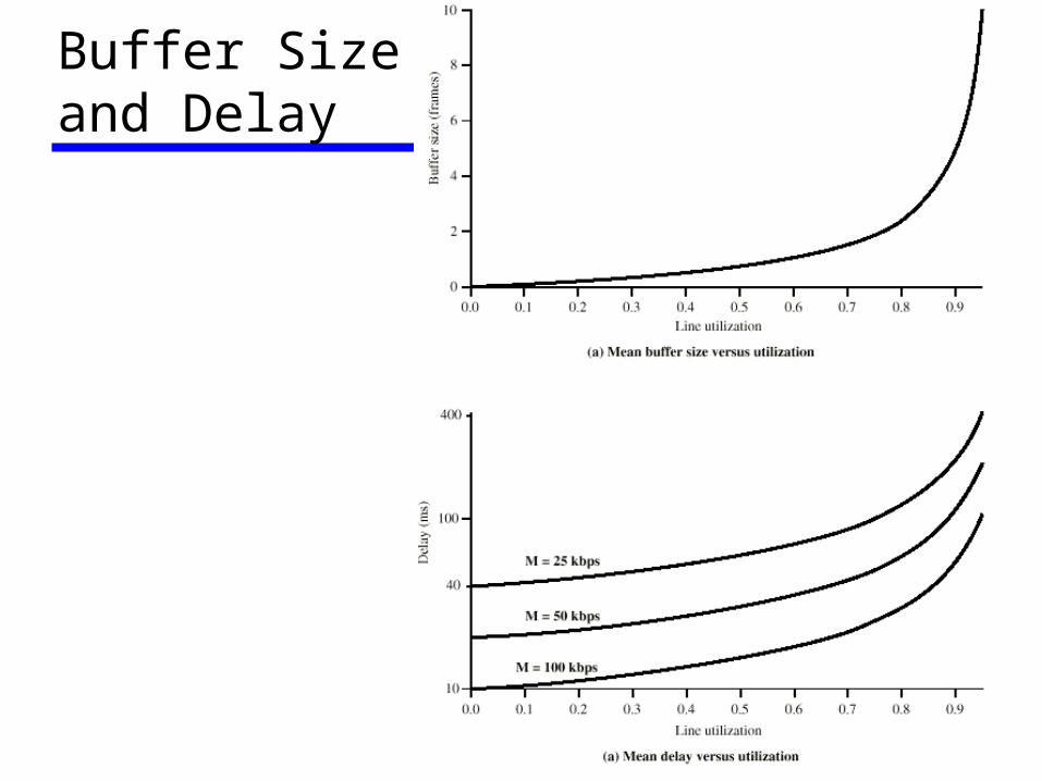
Buffer Size and Delay
Code Division Multiplexing Rather than assign specific time slots or
frequency bands to users, spreading codes are ditributed.
By spreading the spectrum of the users, the energy from each user over a freq. band is small and can be super-imposed Inherently takes advantage of statistical
distribution of input Allows for dynamic resource allocation
Asymmetrical Digital Subscriber Line ADSL Link between subscriber and network
Local loop Uses currently installed twisted pair cable
Can carry broader spectrum 1 MHz or more
ADSL Design Asymmetric
Greater capacity downstream than upstream Frequency division multiplexing
Lowest 25kHz for voice Plain old telephone service (POTS)
Use echo cancellation or FDM to give two bands
Use FDM within bands Range 5.5km
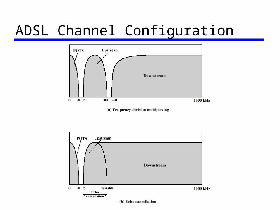
ADSL Channel Configuration
Discrete Multitone DMT Multiple carrier signals at different frequencies Some bits on each channel 4kHz subchannels Send test signal and use subchannels with
better signal to noise ratio 256 downstream subchannels at 4kHz
(60kbps) 15.36MHz Impairments bring this down to 1.5Mbps to 9Mbps
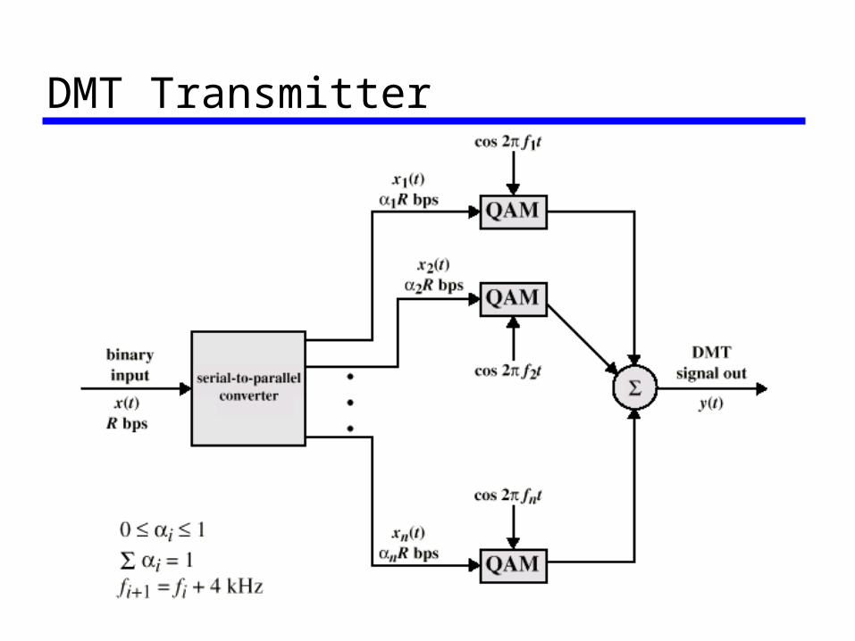
DMT Transmitter
xDSL High data rate DSL Single line DSL Very high data rate DSL
Required Reading Stallings chapter 8 Web sites on
ADSL SONET