
Computer Networks Lab -...
14
1 Computer Networks Lab Room: BB 219 Additional Information: http://ti.uni-due.de/ti/en/education/teaching/ss16/netlab 1. Practical Training: Network planning and installation of a file server 2. Practical Training: Web server installation and dynamic Web pages 3. Practical Training: Installation and configuration of a Firewall 4. Practical Training: Installation of a VPN for the connection of two networks 5. Practical Training: Programming attempt; Client/Server connection over Sockets 6. Practical Training: Network Monitoring Name: Matriculation No.: Supervisor Signature: Contact: Joachim Zumbrägel BB 320 Tel: 0203/379-3978 E-Mail: [email protected] 2 Equipment for each group: - 1 Server computer (OS: Windows Server 2008 Standard) - 1 Client computer (OS: Windows XP Professional) - 1 Computer as Router / Gateway (OS: Linux) - 1 Switch - Network cables 1. Introduction Computers in small companies without much space or those in households are commonly connected to form a network in order to share resources (e.g. printer, Internet, files). The setup of a (simple) network with current operating systems is relatively trivial. For networks with up to ten computers a Peer to Peer network is suitable. ”Peer to Peer” implies that computers in such a network are considered equal and thus a central Server for administrating data traffic is not required. In the Windows OS environment a Peer to Peer network structure is called “Workgroup” and is based on the same principle. For larger networks, however, at least one Server should be used to centrally administrate network resources. This type of structure is called “Domain” in the Windows OS environment. 2. Network basics In this practical training both models are to be successively carried out. Before configuring your computers for the network, the physical connections have to be created. All computers in the laboratory are equipped with a network card and a network cable. In addition, each group is provided with a SWITCH. The STAR configuration will be physically implemented (see Fig. 1.2). In order to exchange data in a network, computers must speak the “same language”, which is the role of Network Protocols. They specify the common language in each case. Usually, in local networks the TCP/IP protocol is used, upon which the Internet is also based. In Windows Server 2008, TCP/IP is installed with the operating system and remains active after the installation. We just have to configure it.
Transcript of Computer Networks Lab -...
1
Computer Networks Lab
Room: BB 219
Additional Information: http://ti.uni-due.de/ti/en/education/teaching/ss16/netlab
1. Practical Training: Network planning and installation of a file server
2. Practical Training: Web server installation and dynamic Web pages
3. Practical Training: Installation and configuration of a Firewall
4. Practical Training: Installation of a VPN for the connection of two networks
5. Practical Training: Programming attempt; Client/Server connection over Sockets
6. Practical Training: Network Monitoring
Name:
Matriculation No.:
Supervisor Signature:
Contact: Joachim Zumbrägel
BB 320 Tel: 0203/379-3978 E-Mail: [email protected]
2
Equipment for each group:
- 1 Server computer (OS: Windows Server 2008 Standard) - 1 Client computer (OS: Windows XP Professional) - 1 Computer as Router / Gateway (OS: Linux) - 1 Switch - Network cables
1. Introduction Computers in small companies without much space or those in households are commonly connected to form a network in order to share resources (e.g. printer, Internet, files). The setup of a (simple) network with current operating systems is relatively trivial. For networks with up to ten computers a Peer to Peer network is suitable. ”Peer to Peer” implies that computers in such a network are considered equal and thus a central Server for administrating data traffic is not required. In the Windows OS environment a Peer to Peer network structure is called “Workgroup” and is based on the same principle. For larger networks, however, at least one Server should be used to centrally administrate network resources. This type of structure is called “Domain” in the Windows OS environment.
2. Network basics In this practical training both models are to be successively carried out. Before configuring your computers for the network, the physical connections have to be created. All computers in the laboratory are equipped with a network card and a network cable. In addition, each group is provided with a SWITCH. The STAR configuration will be physically implemented (see Fig. 1.2). In order to exchange data in a network, computers must speak the “same language”, which is the role of Network Protocols. They specify the common language in each case. Usually, in local networks the TCP/IP protocol is used, upon which the Internet is also based. In Windows Server 2008, TCP/IP is installed with the operating system and remains active after the installation. We just have to configure it.
3
Before we do that, we need to enter some general information (e.g. Computer Name and Workgroup or Domain Name). Question 1: What is the Computer Name for?
Question 2: What is the difference between Workgroup and Domain?
2.1 The Workgroup Model Each computer in your network needs to have a Name and has to belong to a Workgroup (workgroups are protocol independent). The Name of each computer must be unique, thus it cannot occur more than once in a network. To change the settings mentioned above you need to proceed as follows:
• Go to Start → Control Panel • On Windows XP Pro
navigate through Performance and Maintenance and open System. Choose the second TAB named “Computer Name” On Windows Server 2008 open System and choose “Change settings” under the “Computer name, domain, and workgroup settings” field
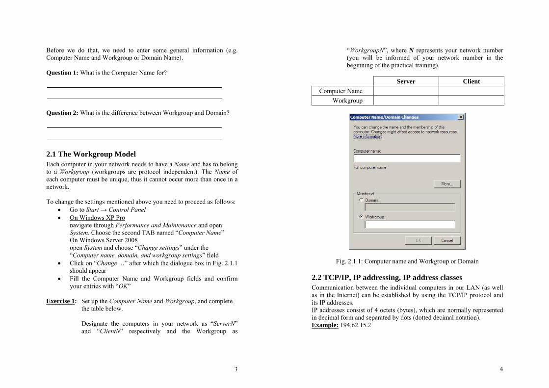
• Click on “Change …” after which the dialogue box in Fig. 2.1.1 should appear
• Fill the Computer Name and Workgroup fields and confirm your entries with “OK”
Exercise 1: Set up the Computer Name and Workgroup, and complete
the table below.
Designate the computers in your network as “ServerN” and “ClientN” respectively and the Workgroup as
4
“WorkgroupN”, where N represents your network number (you will be informed of your network number in the beginning of the practical training).
Server Client
Computer Name Workgroup
Fig. 2.1.1: Computer name and Workgroup or Domain
2.2 TCP/IP, IP addressing, IP address classes Communication between the individual computers in our LAN (as well as in the Internet) can be established by using the TCP/IP protocol and its IP addresses. IP addresses consist of 4 octets (bytes), which are normally represented in decimal form and separated by dots (dotted decimal notation). Example: 194.62.15.2
5
This form of representation is used only for the input and/or display of IP addresses on the computer. Internally, however, the computer always works with the binary representation of IP addresses. Example: 11000010.00111110.00001111.00000010 (the computer does not set the dots between the individual octets. They were used here only to facilitate and/or to distinguish between the individual values of the binary representation of the "dotted decimal notation"). IP addresses consist of two parts:
• Network address • Host address
These two parts are identified through the “subnet mask”. By definition the network part of an IP address is represented by 1s and the host part by 0s. The network part identifies the network address, where the computer (associated with its IP address) is located. The host part identifies the computer address within that network. This structure allows TCP/IP to be defined as a routing protocol. Example: IP Address: 194.62.15.2 11000010.00111110.00001111.00000010 Subnet mask: 255.255.255.0 11111111.11111111.11111111.00000000 The first 3 bytes represent the Network address (1s) and the last byte represents the Host address (0s).
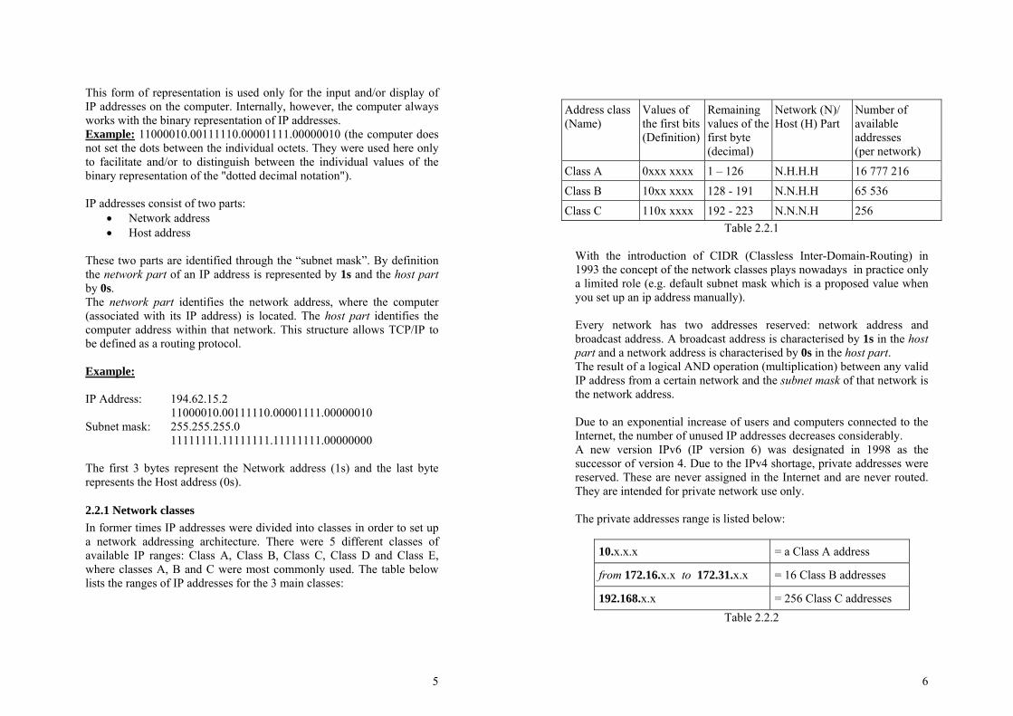
2.2.1 Network classes In former times IP addresses were divided into classes in order to set up a network addressing architecture. There were 5 different classes of available IP ranges: Class A, Class B, Class C, Class D and Class E, where classes A, B and C were most commonly used. The table below lists the ranges of IP addresses for the 3 main classes:
6
Address class(Name)
Values of the first bits(Definition)
Remaining values of the first byte (decimal)
Network (N)/ Host (H) Part
Number of available addresses (per network)
Class A 0xxx xxxx 1 – 126 N.H.H.H 16 777 216
Class B 10xx xxxx 128 - 191 N.N.H.H 65 536
Class C 110x xxxx 192 - 223 N.N.N.H 256 Table 2.2.1
With the introduction of CIDR (Classless Inter-Domain-Routing) in 1993 the concept of the network classes plays nowadays in practice only a limited role (e.g. default subnet mask which is a proposed value when you set up an ip address manually). Every network has two addresses reserved: network address and broadcast address. A broadcast address is characterised by 1s in the host part and a network address is characterised by 0s in the host part. The result of a logical AND operation (multiplication) between any valid IP address from a certain network and the subnet mask of that network is the network address. Due to an exponential increase of users and computers connected to the Internet, the number of unused IP addresses decreases considerably. A new version IPv6 (IP version 6) was designated in 1998 as the successor of version 4. Due to the IPv4 shortage, private addresses were reserved. These are never assigned in the Internet and are never routed. They are intended for private network use only. The private addresses range is listed below:
10.x.x.x = a Class A address
from 172.16.x.x to 172.31.x.x = 16 Class B addresses
192.168.x.x = 256 Class C addresses Table 2.2.2
7
The address 127.0.0.1: The address 127.0.0.1 plays a special role - by definition it always addresses the local computer. It generally holds the name "local host". According to standard, the use of the network 127.x.x.x is inadmissible ("An address with 127.x.x.x should never be part of a network!"). The 127.0.0.1 can only be used to examine the configuration of the particular computer (ISO Layers 3 to 7)!
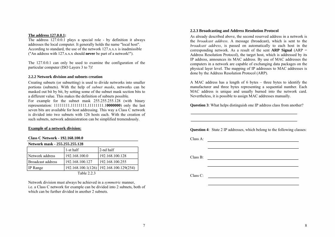
2.2.2 Network division and subnets creation Creating subnets (or subnetting) is used to divide networks into smaller portions (subnets). With the help of subnet masks, networks can be masked out bit by bit, by setting some of the subnet mask section bits to a different value. This makes the definition of subnets possible. For example for the subnet mask 255.255.255.128 (with binary representation: 11111111.11111111.11111111.10000000) only the last seven bits are available for host addressing. This way a Class C network is divided into two subnets with 126 hosts each. With the creation of such subnets, network administration can be simplified tremendously. Example of a network division: Class C Network - 192.168.100.0 Network mask - 255.255.255.128 1-st half 2-nd half Network address 192.168.100.0 192.168.100.128 Broadcast address 192.168.100.127 192.168.100.255 IP Range 192.168.100.1(126) 192.168.100.129(254)
Table 2.2.3
Network division must always be achieved in a symmetric manner, i.e. a Class C network for example can be divided into 2 subnets, both of which can be further divided in another 2 subnets.
8
2.2.3 Broadcasting and Address Resolution Protocol As already described above, the second reserved address in a network is the broadcast address. A message (broadcast), which is sent to the broadcast address, is passed on automatically to each host in the corresponding network. As a result of the sent ARP Signal (ARP = Address Resolution Protocol), the target host, which is addressed by its IP address, announces its MAC address. By use of MAC addresses the computers in a network are capable of exchanging data packages on the physical layer level. The mapping of IP addresses to MAC addresses is done by the Address Resolution Protocol (ARP). A MAC address has a length of 6 bytes – three bytes to identify the manufacturer and three bytes representing a sequential number. Each MAC address is unique and usually burned into the network card. Nevertheless, it is possible to assign MAC addresses manually. Question 3: What helps distinguish one IP address class from another?
Question 4: State 2 IP addresses, which belong to the following classes: Class A: Class B: Class C:
9
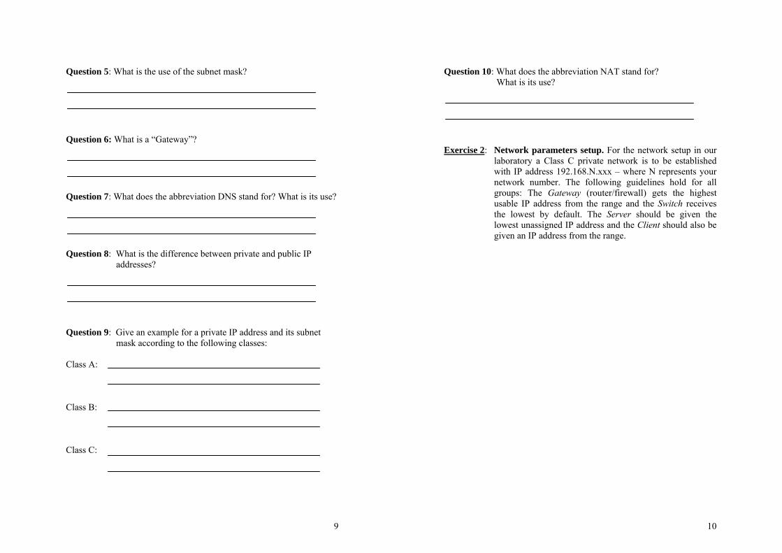
Question 5: What is the use of the subnet mask?
Question 6: What is a “Gateway”?
Question 7: What does the abbreviation DNS stand for? What is its use?
Question 8: What is the difference between private and public IP
addresses?
Question 9: Give an example for a private IP address and its subnet
mask according to the following classes: Class A: Class B: Class C:
10
Question 10: What does the abbreviation NAT stand for? What is its use?
Exercise 2: Network parameters setup. For the network setup in our
laboratory a Class C private network is to be established with IP address 192.168.N.xxx – where N represents your network number. The following guidelines hold for all groups: The Gateway (router/firewall) gets the highest usable IP address from the range and the Switch receives the lowest by default. The Server should be given the lowest unassigned IP address and the Client should also be given an IP address from the range.
11
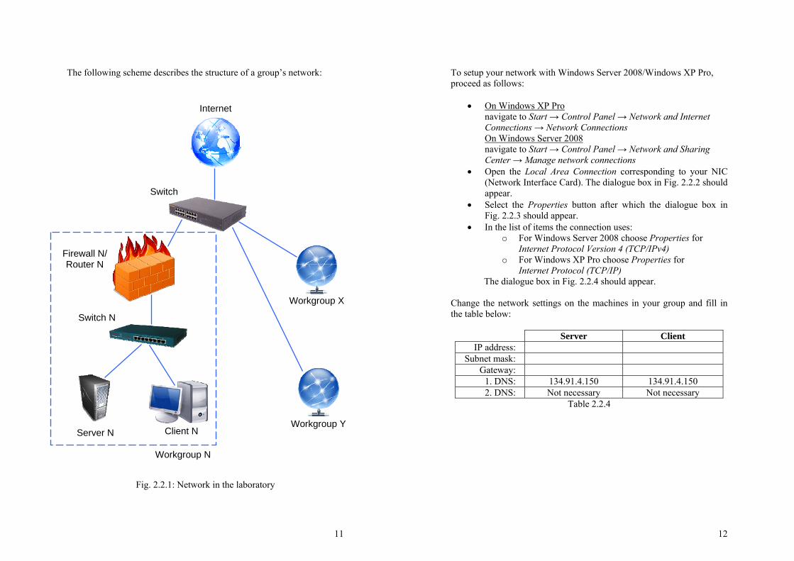
The following scheme describes the structure of a group’s network:
Fig. 2.2.1: Network in the laboratory
Switch N
Switch
Workgroup Y
Workgroup X
Firewall N/ Router N
Server N Client N
Internet
Workgroup N
12
To setup your network with Windows Server 2008/Windows XP Pro, proceed as follows:
• On Windows XP Pro navigate to Start → Control Panel → Network and Internet Connections → Network Connections On Windows Server 2008 navigate to Start → Control Panel → Network and Sharing Center → Manage network connections
• Open the Local Area Connection corresponding to your NIC (Network Interface Card). The dialogue box in Fig. 2.2.2 should appear.
• Select the Properties button after which the dialogue box in Fig. 2.2.3 should appear.
• In the list of items the connection uses: o For Windows Server 2008 choose Properties for
Internet Protocol Version 4 (TCP/IPv4) o For Windows XP Pro choose Properties for
Internet Protocol (TCP/IP) The dialogue box in Fig. 2.2.4 should appear.
Change the network settings on the machines in your group and fill in the table below:
Server Client IP address:
Subnet mask: Gateway:
1. DNS: 134.91.4.150 134.91.4.150 2. DNS: Not necessary Not necessary
Table 2.2.4
13
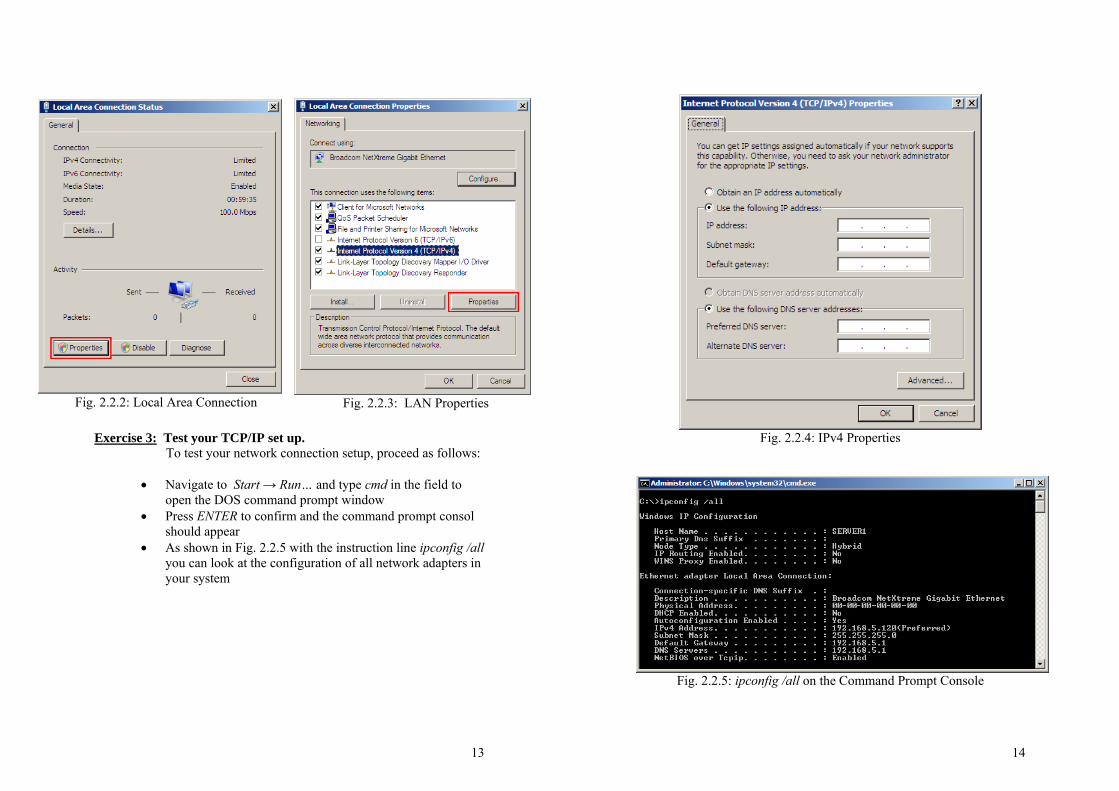
Fig. 2.2.2: Local Area Connection
Fig. 2.2.3: LAN Properties
Exercise 3: Test your TCP/IP set up.
To test your network connection setup, proceed as follows:
• Navigate to Start → Run… and type cmd in the field to open the DOS command prompt window
• Press ENTER to confirm and the command prompt consol should appear
• As shown in Fig. 2.2.5 with the instruction line ipconfig /all you can look at the configuration of all network adapters in your system
14
Fig. 2.2.4: IPv4 Properties
Fig. 2.2.5: ipconfig /all on the Command Prompt Console
15
Compare the output of the console with the configuration you entered earlier in Table 2.2.4. To check if the computers (ServerN, ClientN, and Gateway) are communicating with each other use the command line – ping <followed by the IP address> - e.g.: ping 192.168.82.1<press enter> As a result of the “ping” command line you should get four answers from the computer you “pinged”. Repeat the same command for all computers you configured. Ping the “localhost”, your local IP address and the IP addresses in your network.
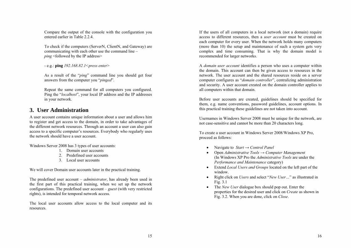
3. User Administration A user account contains unique information about a user and allows him to register and get access to the domain, in order to take advantages of the different network resources. Through an account a user can also gain access to a specific computer’s resources. Everybody who regularly uses the network should have a user account. Windows Server 2008 has 3 types of user accounts:
1. Domain user accounts 2. Predefined user accounts 3. Local user accounts
We will cover Domain user accounts later in the practical training. The predefined user account – administrator, has already been used in the first part of this practical training, when we set up the network configurations. The predefined user account – guest (with very restricted rights), is intended for temporal network access. The local user accounts allow access to the local computer and its resources.
16
If the users of all computers in a local network (not a domain) require access to different resources, then a user account must be created on each computer for every user. When the network holds many computers (more than 10) the setup and maintenance of such a system gets very complex and time consuming. That is why the domain model is recommended for larger networks. A domain user account identifies a person who uses a computer within the domain. This account can then be given access to resources in the network. The user account and the shared resources reside on a server computer configures as “domain controller”, centralizing administration and security. A user account created on the domain controller applies to all computers within that domain. Before user accounts are created, guidelines should be specified for them, e.g. name conventions, password guidelines, account options. In this practical training these guidelines are not taken into account. Usernames in Windows Server 2008 must be unique for the network, are not case-sensitive and cannot be more than 20 characters long. To create a user account in Windows Server 2008/Windows XP Pro, proceed as follows:
• Navigate to Start → Control Panel • Open Administrative Tools → Computer Management
(In Windows XP Pro the Administrative Tools are under the Performance and Maintenance category)
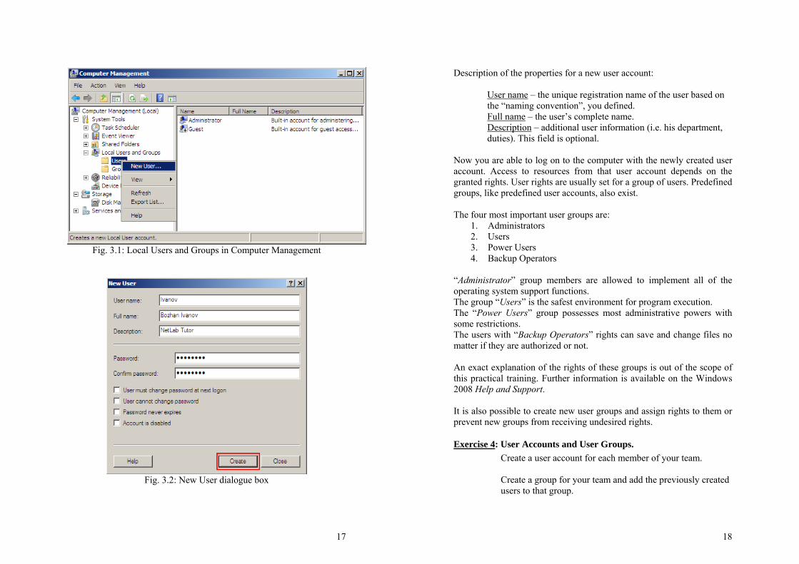
• Extend Local Users and Groups located on the left part of the window.
• Right click on Users and select “New User…” as illustrated in Fig. 3.1
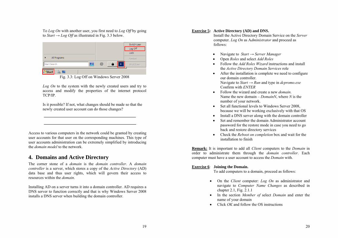
• The New User dialogue box should pop out. Enter the properties for the desired user and click on Create as shown in Fig. 3.2. When you are done, click on Close.
17
Fig. 3.1: Local Users and Groups in Computer Management
Fig. 3.2: New User dialogue box
18
Description of the properties for a new user account:
User name – the unique registration name of the user based on the “naming convention”, you defined. Full name – the user’s complete name. Description – additional user information (i.e. his department, duties). This field is optional.
Now you are able to log on to the computer with the newly created user account. Access to resources from that user account depends on the granted rights. User rights are usually set for a group of users. Predefined groups, like predefined user accounts, also exist. The four most important user groups are:
1. Administrators 2. Users 3. Power Users 4. Backup Operators
“Administrator” group members are allowed to implement all of the operating system support functions. The group “Users” is the safest environment for program execution. The “Power Users” group possesses most administrative powers with some restrictions. The users with “Backup Operators” rights can save and change files no matter if they are authorized or not. An exact explanation of the rights of these groups is out of the scope of this practical training. Further information is available on the Windows 2008 Help and Support. It is also possible to create new user groups and assign rights to them or prevent new groups from receiving undesired rights.
Exercise 4: User Accounts and User Groups. Create a user account for each member of your team.
Create a group for your team and add the previously created users to that group.
19
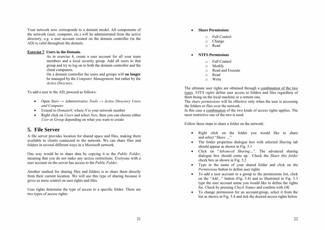
To Log On with another user, you first need to Log Off by going to Start → Log Off as illustrated in Fig. 3.3 below.
Fig. 3.3: Log Off on Windows Server 2008
Log On to the system with the newly created users and try to access and modify the properties of the internet protocol TCP/IP. Is it possible? If not, what changes should be made so that the newly created user account can do those changes?
Access to various computers in the network could be granted by creating user accounts for that user on the corresponding machines. This type of user accounts administration can be extremely simplified by introducing the domain model to the network.
4. Domains and Active Directory The corner stone of a domain is the domain controller. A domain controller is a server, which stores a copy of the Active Directory (AD) data base and thus user rights, which will govern their access to resources within the domain. Installing AD on a server turns it into a domain controller. AD requires a DNS server to function correctly and that is why Windows Server 2008 installs a DNS server when building the domain controller.
20
Exercise 5: Active Directory (AD) and DNS. Install the Active Directory Domain Service on the Server computer. Log On as Administrator and proceed as follows:
• Navigate to Start → Server Manager • Open Roles and select Add Roles • Follow the Add Roles Wizard instructions and install
the Active Directory Domain Services role • After the installation is complete we need to configure
our domain controller. Navigate to Start → Run and type in dcpromo.exe Confirm with ENTER
• Follow the wizard and create a new domain. Name the new domain – DomainN, where N is the number of your network.
• Set all functional levels to Windows Server 2008, because we will be working exclusively with that OS
• Install a DNS server along with the domain controller • Set and remember the domain Administrator account
password for the restore mode in case you need to go back and restore directory services
• Check the Reboot on completion box and wait for the installation to finish
Remark: It is important to add all Client computers to the Domain in order to administrate them through the domain controller. Each computer must have a user account to access the Domain with. Exercise 6: Joining the Domain. To add computers to a domain, proceed as follows:
• On the Client computer: Log On as administrator and navigate to Computer Name Changes as described in chapter 2.1, Fig. 2.1.1
• In the section Member of select Domain and enter the name of your domain
• Click OK and follow the OS instructions
21
Your network now corresponds to a domain model. All components of the network (user, computer, etc.) will be administrated from the active directory, e.g. a user account created on the domain controller (in the AD) is valid throughout the domain. Exercise 7: Users in the Domain.
As in exercise 4, create a user account for all your team members and a local security group. Add all users to that group and try to log on to both the domain controller and the client computers. On a domain controller the users and groups will no longer be managed by the Computer Management, but rather by the Active Directory.
To add a user to the AD, proceed as follows:
• Open Start → Administrative Tools → Active Directory Users and Computer
• Extend to DomainN, where N is your network number • Right click on Users and select New, then you can choose either
User or Group depending on what you want to create
5. File Server A file server provides location for shared space and files, making them available to clients connected to the network. We can share files and folders in several different ways in a Microsoft network. One way would be to share data by copying it to the Public Folder, meaning that you do not make any access restrictions. Everyone with a user account on the server has access to the Public Folder. Another method for sharing files and folders is to share them directly from their current location. We will use this type of sharing because it gives us more control on user rights and files. User rights determine the type of access to a specific folder. There are two types of access rights:
22
• Share Permissions
o Full Control o Change o Read
• NTFS Permissions
o Full Control o Modify o Read and Execute o Read o Write
The ultimate user rights are obtained through a combination of the two types. NTFS rights define user access to folders and files regardless of them being on the local machine or a remote one. The share permissions will be effective only when the user is accessing the folders or files over the network. In this case a combination of the two kinds of access rights applies. The most restrictive one of the two is used. Follow these steps to share a folder on the network:
• Right click on the folder you would like to share and select “Share …”
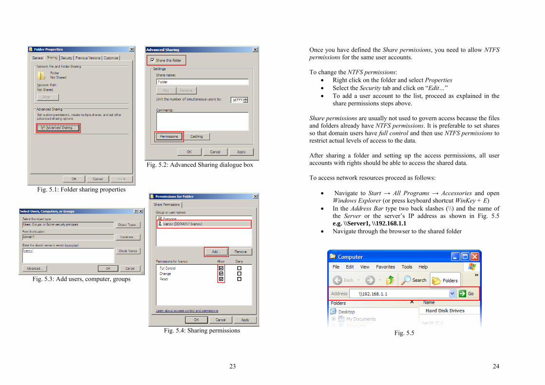
• The folder properties dialogue box with selected Sharing tab should appear as shown in Fig. 5.1
• Click on “Advanced Sharing…”. The advanced sharing dialogue box should come up. Check the Share this folder check box as shown in Fig. 5.2
• Type in the name of your shared folder and click on the Permissions button to define user rights
• To add a user account or a group to the permissions list, click on the “Add…” button (Fig. 5.4) and as illustrated in Fig. 5.3 type the user account name you would like to define the rights for. Check by pressing Check Names and confirm with OK
• To change permission for an account/group, select it from the list as shown in Fig. 5.4 and tick the desired access rights below
23
Fig. 5.1: Folder sharing properties
Fig. 5.2: Advanced Sharing dialogue box
Fig. 5.3: Add users, computer, groups
Fig. 5.4: Sharing permissions
24
Once you have defined the Share permissions, you need to allow NTFS permissions for the same user accounts. To change the NTFS permissions:
• Right click on the folder and select Properties • Select the Security tab and click on “Edit…” • To add a user account to the list, proceed as explained in the
share permissions steps above. Share permissions are usually not used to govern access because the files and folders already have NTFS permissions. It is preferable to set shares so that domain users have full control and then use NTFS permissions to restrict actual levels of access to the data. After sharing a folder and setting up the access permissions, all user accounts with rights should be able to access the shared data. To access network resources proceed as follows:
• Navigate to Start → All Programs → Accessories and open Windows Explorer (or press keyboard shortcut WinKey + E)
• In the Address Bar type two back slashes (\\) and the name of the Server or the server’s IP address as shown in Fig. 5.5 e.g. \\Server1, \\192.168.1.1
• Navigate through the browser to the shared folder
Fig. 5.5
25
Exercise 9: Sharing resources Create a folder on the domain controller (Server computer). Give two of the previously created user accounts the NTFS permission – Modify and the other two the NTFS permission – Read. Create a text file in the newly created folder. Share the folder with Share permission – Full control for the group created in Exercise 7. Try now to access the text file from the Client computer with all user accounts. Try to change the file and save the changes. Does it work for all four users? Which work and which do not?
Change the Share permission of the group to Read and try once again to access the text file from the Client computer using the four users. Try to make some changes to the text file and save changes them. Could you save the changes? Why?
6. DHCP Server As we learned in the beginning of this practical training it is possible to manually setup the IP address of each computer in the network. However, in the case of larger networks an automatic distribution of IP addresses is highly recommended. This is where the DHCP Server comes into place (though it can achieve more). DHCP stands for “Dynamic Host Configuration Protocol”. It is a TCP/IP standard and its goal is to alleviate the complexity of IP addressing management (including other configuration details that come with it) by centralizing it through a Server on the network.
26
Exercise 10: DHCP Server Install a DHCP Server for your network configuration.
To install a DHCP Server Role on Windows Server 2008 proceed as follows:
• Navigate to Start → Server Manager • Open Roles and select Add Roles • Follow the Add Roles Wizard instructions and install
the DHCP Server role • When asked, select the network connection, which you
want the DHCP Server to manage • For the next step, type in the parent domain (your
current domain) and the IP address of the DNS Server in your network
• Do not install a WINS Server and continue right on • Add the scope of the IP addresses in your network by
pressing the “Add…” button in the next wizard step • We do not need a DHCPv6 because we will not use the
IPv6 in our network • Authorize the DCHP Server with the current
credentials
After the installation it is possible to configure different parameters in the DHCP console like Gateway, DNS, WINS, etc. To reconfigure your DHCP Server, navigate to: Start → Administrative Tools → DHCP Expand the Server and the IPv4 to reconfigure if needed. Log On as administrator on the Client computer and change the TCP/IP configuration to “Obtain an IP address automatically” and “Obtain DNS server address automatically” Verify with “ipconfig/ all” that the Client computer got a correct TCP/IP configuration from the DHCP Server. Using the command “ping” make sure that the Client computer can communicate with the other computers.

27
Notes:


