
Computer Networking Course book - Education Observer
60
Computer Networking Computer Networking Course book: Computer Networking Top Down approach 3 rd edition B Ji k d k ith By Jim kurose and keith ross Reference book: Reference book: Computer Networks 3 rd edition B A d ST b Introduction 1-1 By Andrew S.Tanenbaum
Transcript of Computer Networking Course book - Education Observer

Computer NetworkingComputer Networking
Course book:Computer NetworkingTop Down approach 3rd editionB Ji k d k ith By Jim kurose and keith ross
Reference book:Reference book:Computer Networks 3rd editionB A d S T b
Introduction 1-1
By Andrew S.Tanenbaum
Chapter 1pComputer Networks and the Internetand the Internet
Computer Networking: A Top Down Approach Featuring the Internet, 3rd edition 3rd edition. Jim Kurose, Keith Ross
Introduction 1-2

Chapter 1: IntroductionChapter 1 IntroductionOur goal: Overview:
get “feel” and terminologymore depth detail
what’s the Internetwhat’s a protocol?network edgemore depth, detail
later in courseapproach:
network edgenetwork coreaccess net physical media
use Internet as example
access net, physical mediaInternet/ISP structureprotocol layers, service modelsp ynetwork modeling
Introduction 1-3

Chapter 1: roadmapChapter roadmap
1.1 What is the Internet?1.1 What is the Internet?1.2 Network edge1 3 Network core1.3 Network core1.4 Network access and physical media1 5 Internet structure and ISPs1.5 Internet structure and ISPs1.6 Protocol layers, service models1 7 History1.7 History
Introduction 1-4

What’s the Internet: “nuts and bolts” viewmillions of connected computing devices: hosts
router workstationcomputing devices hosts = end systemsrunning network apps local ISP
servermobile
communication linksfiber, copper, radio, satellite regional ISPtransmission rate = bandwidth
routers: forward packets
regional ISP
routers: forward packets (chunks of data)
company
Introduction 1-5
network

What’s the Internet: “nuts and bolts” view
protocols control sending, receiving of msgs
router workstationreceiving of msgs
e.g., TCP, IP, HTTP, FTP, PPPInternet: “network of local ISP
servermobile
networks”loosely hierarchicalpublic Internet versus regional ISPpublic Internet versus private intranet
Internet standards
regional ISP
RFC: Request for commentsIETF: Internet Engineering Task Force company
Introduction 1-6
network

What’s the Internet: a service viewcommunication infrastructure enables fdistributed applications:
Web, email, games, e-commerce file sharingcommerce, file sharing
communication services provided to apps:
Connectionless unreliableconnection-oriented reliable
Introduction 1-7

What’s a protocol?What s a protocol?human protocols:
“ h t’ th ti ?”network protocols:
hi th th “what’s the time?”“I have a question”introductions
machines rather than humansall communication introductions
… specific msgs sent
all communication activity in Internet governed by protocols
… specific actions taken when msgs received, or other events
protocols define format, order of msgs sent and received among network or other events received among network
entities, and actions taken on msg
Introduction 1-8
transmission, receipt

What’s a protocol?What s a protocol?a human protocol and a computer network protocol:
Hi TCP connection
HiGot the
TCP connectionreq
TCP connectionresponseGot the
time?2:00
responseGet http://www.awl.com/kurose-ross
<file><file>time
Introduction 1-9

Chapter 1: roadmapChapter roadmap
1.1 What is the Internet?1.1 What is the Internet?1.2 Network edge1 3 Network core1.3 Network core1.4 Network access and physical media1 5 Internet structure and ISPs1.5 Internet structure and ISPs1.6 Protocol layers, service models1 7 History1.7 History
Introduction 1-10

A closer look at network structure:
network edge:network edge:applications and hostsnetwork core:
routersnetwork of networks
t k access networks, physical media:communication links
Introduction 1-11
communication links

The network edge:The network edgeend systems (hosts):
run application programsrun application programse.g. Web, emailat “edge of network”
li t/ d lclient/server modelclient host requests, receives service from always-on server
W b b / l e.g. Web browser/server; email client/server
peer-peer model:minimal (or no) use of dedicated serverse.g. Gnutella, KaZaA,bit torrent
Introduction 1-12

Network edge: connection-oriented serviceg
Goal: data transfer TCP service [RFC 793]Goal: data transfer between end systemshandshaking: setup ( f ) d
TCP service [RFC 793]reliable, in-order byte-stream data transfer
(prepare for) data transfer ahead of time
Hello, hello back human
loss: acknowledgements and retransmissions
flow control:H o, h o ac human protocolset up “state” in two communicating hosts
flow controlsender won’t overwhelm receiver
congestion control:mmu gTCP - Transmission Control Protocol
I ’ i
congestion control:senders “slow down sending rate” when network
n st d
Introduction 1-13
Internet’s connection-oriented service
congested

Network edge: connectionless serviceg
Goal: data transfer App’s using TCP:Goal: data transfer between end systems
same as before!DP D
App s using TCP:HTTP (Web), FTP (file transfer), Telnet ( l ) P UDP - User Datagram
Protocol [RFC 768]: connectionless
(remote login), SMTP (email)
connectionless unreliable data transfer
App’s using UDP:streaming media
no flow controlno congestion control
streaming media, teleconferencing, DNS, Internet telephony
Introduction 1-14

Chapter 1: roadmapChapter roadmap
1.1 What is the Internet?1.1 What is the Internet?1.2 Network edge1 3 Network core1.3 Network core1.4 Network access and physical media1 5 Internet structure and ISPs1.5 Internet structure and ISPs1.6 Protocol layers, service models1 7 History1.7 History
Introduction 1-15

The Network CoreThe Network Core
mesh of interconnected froutersthe fundamental
sti h is d t question: how is data transferred through net?
circuit switching:c rcu t sw tch ngdedicated circuit per call: telephone net
k t it hi d t packet-switching: data sent thru net in discrete “chunks”
Introduction 1-16

Network Core: Circuit Switchingg
End-end resources End end resources reserved for “call”link bandwidth, switch capacitydedicated resources: no sharingno sharingcircuit-like (guaranteed) (g )performancecall setup required
Introduction 1-17

Network Core: Circuit Switchinggnetwork resources
( b d idth) dividing link bandwidth
“ ”(e.g., bandwidth) divided into “pieces”pieces allocated to calls
into “pieces”frequency divisiontime divisionpieces allocated to calls
resource piece idle if not used by owning call
time division
y g(no sharing)
Introduction 1-18

Circuit Switching: FDM and TDMC rcu t Sw tch ng FDM and DM
FDM 4 usersExample:
frequency
4 users
frequency
timeTDM
frequency
Introduction 1-19time

Numerical exampleNumer cal example
How long does it take to send a file of How long does it take to send a file of 640,000 bits from host A to host B over a circuit-switched network?
All links are 1.536 MbpsEach link uses TDM with 24 slots500 msec to establish end-to-end circuit
W k it t!Work it out!
Introduction 1-20

Network Core: Packet Switchinggeach end-end data stream
divided into packetsresource contention:
t divided into packetsuser A, B packets sharenetwork resources
aggregate resource demand can exceed amount available
each packet uses full link bandwidth
d d d
congestion: packets queue, wait for link uset d f d resources used as needed store and forward:
packets move one hop at a time
Node receives complete packet before forwarding
Bandwidth division into “pieces”Dedicated allocationResource reservation
Introduction 1-21
Resource reservation

Packet Switching: Statistical Multiplexingg p g
A C10 Mb/sEthernet statistical multiplexing
B1.5 Mb/s
p g
Bqueue of packetswaiting for output
link
D E
Sequence of A & B packets does not have fixed pattern statistical multiplexing.
In TDM each host gets same slot in revolving TDM
Introduction 1-22
In TDM each host gets same slot in revolving TDM frame.

Packet switching versus circuit switchingg g
Packet switching allows more users to use network!
1 Mb/s linkeach user:
k / h “100 kb/s when “active”active 10% of time
N userscircuit-switching:
10 usersk t it hi
N users1 Mbps link
packet switching: with 35 users, probability > 10 active
Introduction 1-23
less than .0004

Packet switching versus circuit switchingg g
Is packet switching a “slam dunk winner?”
Great for bursty dataresource sharingsimpler, no call setup
Excessive congestion: packet delay and losspr t c ls needed f r reli ble d t tr nsfer protocols needed for reliable data transfer, congestion control
Q: How to provide circuit-like behavior?Q pbandwidth guarantees needed for audio/video apps
Introduction 1-24
still an unsolved problem (chapter 6)

Packet-switching: store-and-forwardg f
R R RL
Takes L/R seconds to transmit (push out)
Example:L 7 5 Mbits
R R R
transmit (push out) packet of L bits on to link or R bps
L = 7.5 MbitsR = 1.5 Mbpsdelay = 15 sec
Entire packet must arrive at router before it can be transmitted
delay = 15 sec
it can be transmitted on next link: store and forwardd l 3L/R
Introduction 1-25
delay = 3L/R

Packet-switched networks: forwardingg
Goal: move packets through routers from source to destinationdestination
we’ll study several path selection (i.e. routing) algorithms (chapter 4)
d kdatagram network:destination address in packet determines next hoproutes may change during sessionroutes may change during sessionanalogy: driving, asking directions
virtual circuit network:h k ( l D) each packet carries tag (virtual circuit ID), tag
determines next hopfixed path determined at call setup time, remains fixed h ll
Introduction 1-26
thru callrouters maintain per-call state

Network TaxonomyTelecommunication
networks
Circuit-switched Packet-switchednetworks networks
DFDM TDM Networkswith VCs
DatagramNetworks
• Datagram network is not either connection-oriented or connectionless.• Internet provides both connection-oriented (TCP) and
Introduction 1-27
Internet provides both connection oriented (TCP) and connectionless services (UDP) to apps.

Chapter 1: roadmapChapter roadmap
1.1 What is the Internet?1.1 What is the Internet?1.2 Network edge1 3 Network core1.3 Network core1.4 Network access and physical media1 5 Internet structure and ISPs1.5 Internet structure and ISPs1.6 Protocol layers, service models1 8 History1.8 History
Introduction 1-28

Access networks and physical mediap y
Q: How to connect end systems to edge router?systems to edge router?residential access netsinstitutional access institutional access networks (school, company)
bil t kmobile access networks
Keep in mind: b d id h (bi bandwidth (bits per second) of access network?
Introduction 1-29
shared or dedicated?

Residential access: point to point accessp p
Dialup via modemD a up a mo mup to 56Kbps direct access to router (often less)Can’t surf and phone at same time: can’t be “always on”
d l lADSL: asymmetric digital subscriber lineup to 1 Mbps upstream (today typically < 256 kbps)up to 8 Mbps downstream (today typically < 1 Mbps)up to 8 Mbps downstream (today typically < 1 Mbps)FDM: 50 kHz - 1 MHz for downstream
4 kHz - 50 kHz for upstream
Introduction 1-30
p0 kHz - 4 kHz for ordinary telephone

Residential access: cable modems
HFC: hybrid fiber coaxHFC: hybrid fiber coaxasymmetric: up to 30Mbps downstream, 2 Mbps upstream
network of cable and fiber attaches homes to ISP router
h m s sh ss t t homes share access to router deployment: available via cable TV companies
Introduction 1-31

Residential access: cable modems
Introduction 1-32Diagram: http://www.cabledatacomnews.com/cmic/diagram.html

Cable Network Architecture: Overview
Typically 500 to 5,000 homes
home
cable headend
cable distribution
Introduction 1-33
cable distributionnetwork (simplified)

Cable Network Architecture: Overview
home
cable headend
cable distribution
Introduction 1-34
cable distributionnetwork (simplified)

Cable Network Architecture: Overview
server(s)
home
cable headend
cable distribution
Introduction 1-35
cable distributionnetwork

Cable Network Architecture: Overview
FDM:
VIDEO
VIDEO
VIDEO
VIDEO
VIDEO
VIDEO
DATA
DATA
CONTROL
Channels
O O O O O O A A L
1 2 3 4 5 6 7 8 9
home
cable headend
cable distribution
Introduction 1-36
cable distributionnetwork

Company access: local area networksp y
company/univ local area network (LAN) connects network (LAN) connects end system to edge routerEthernet:
shared or dedicated link connects end system and routerand router10 Mbs, 100Mbps, Gigabit Ethernetg
LANs: chapter 5
Introduction 1-37

Wireless access networksshared wireless access network connects end system network connects end system to router
via base station aka “access p int”
router
point”wireless LANs:
802.11b (WiFi): 11 Mbps
basestation
( ) pwider-area wireless access
provided by telco operator3G 384 kb3G ~ 384 kbps
• Will it happen??WAP/GPRS in Europe
mobilehosts
Introduction 1-38

Home networksTypical home network components:
ADSL or cable modemADSL or cable modemrouter/firewall/NATEthernetwireless accesspoint
wirelesslaptops
router/f ll
cabled
to/fromcable
wirelessaccess
i t
firewallmodemcableheadend
Ethernet
Introduction 1-39
pointEthernet

Physical Mediay
Bit: propagates betweenTwisted Pair (TP)
two insulated copper p p gtransmitter/rcvr pairsphysical link: what lies b t t s itt &
two insulated copper wires
Category 3: traditional h i 10 Mb between transmitter &
receiverguided media:
phone wires, 10 Mbps EthernetCategory 5: 100Mb Eth tgu ded med a
signals propagate in solid media: copper, fiber, coax
unguided media:
100Mbps Ethernet
unguided media:signals propagate freely, e.g., radio
Introduction 1-40

Physical Media: coax, fibery ,
Coaxial cable: Fiber optic cable:glass fiber carrying light two concentric copper
conductorsbidirectional
glass fiber carrying light pulses, each pulse a bithigh-speed operation:bidirectional
baseband:single channel on cable
high-speed point-to-point transmission (e.g., 5 Gps)
low error rate: repeaters legacy Ethernet
broadband:multiple channel on cable
low error rate: repeaters spaced far apart ; immune to electromagnetic noise
multiple channel on cableHFC
Introduction 1-41

Physical media: radioy
signal carried in electromagnetic
Radio link types:terrestrial microwaveelectromagnetic
spectrumno physical “wire”
terrestrial microwavee.g. up to 45 Mbps channels
LAN (e.g., Wifi)p ybidirectionalpropagation
i t ff t
( g )2Mbps, 11Mbps
wide-area (e.g., cellular) 3G h d d f kbenvironment effects:
reflection obstruction by objects
e.g. 3G: hundreds of kbpssatellite
up to 50Mbps channel (or y jinterference
p p (multiple smaller channels)270 msec end-end delaygeosynchronous versus low
Introduction 1-42
geosynchronous versus low altitude

Chapter 1: roadmapChapter roadmap
1.1 What is the Internet?1.1 What is the Internet?1.2 Network edge1 3 Network core1.3 Network core1.4 Network access and physical media1 5 Internet structure and ISPs1.5 Internet structure and ISPs1.6 Protocol layers, service models1 7 History1.7 History
Introduction 1-43

Internet structure: network of networks
roughly hierarchicalat center: “tier-1” ISPs (e.g., UUNet, BBN/Genuity, Sprint, AT&T), national/international coverage
treat each other as equalstreat each other as equals
Ti 1
Tier-1 providers also interconnect
Tier 1 ISPTier-1 providers interconnect (peer)
NAPat public network access points (NAPs)
Tier 1 ISP Tier 1 ISP(p )privately
Introduction 1-44

Tier-1 ISP: e.g., SprintT er ISP e.g., Spr ntSprint US backbone network
Introduction 1-45

Internet structure: network of networks
“Tier-2” ISPs: smaller (often regional) ISPsC i 1 I P ibl h i 2 I PConnect to one or more tier-1 ISPs, possibly other tier-2 ISPs
Tier-2 ISPTier-2 ISPTier-2 ISP pays tier-1 ISP for
Tier-2 ISPs also peer privately with
Tier 1 ISPNAP
tier 1 ISP for connectivity to rest of Internet
tier-2 ISP is t f
each other, interconnect at NAP
Tier 1 ISP Tier 1 ISP
Tier-2 ISP Tier-2 ISP
Tier-2 ISPcustomer oftier-1 provider
Introduction 1-46
Tier 2 ISP Tier 2 ISP

Internet structure: network of networks
“Tier-3” ISPs and local ISPs l h (“ ”) k ( l d )last hop (“access”) network (closest to end systems)
local l llocalISP Tier 3
Tier-2 ISPTier-2 ISP
localISPlocal
ISPlocalISP
ISP Tier 3ISP
Local and tier-3 ISPs are
Tier 1 ISPNAP
customers ofhigher tier ISPsconnecting
Tier 1 ISP Tier 1 ISP
Tier-2 ISP Tier-2 ISP
Tier-2 ISPlocal
connecting them to rest of Internet
Introduction 1-47
Tier 2 ISP Tier 2 ISPlocalISP
localISP
localISP
ISP

Internet structure: network of networks
a packet passes through many networks!
local l llocalISP Tier 3
Tier-2 ISPTier-2 ISP
localISPlocal
ISPlocalISP
ISP Tier 3ISP
Tier 1 ISPNAP
Tier 1 ISP Tier 1 ISP
Tier-2 ISP Tier-2 ISP
Tier-2 ISPlocal
Introduction 1-48
Tier 2 ISP Tier 2 ISPlocalISP
localISP
localISP
ISP

Chapter 1: roadmapChapter roadmap
1.1 What is the Internet?1.1 What is the Internet?1.2 Network edge1 3 Network core1.3 Network core1.4 Network access and physical media1 5 Internet structure and ISPs1.5 Internet structure and ISPs1.6 Protocol layers, service models1 7 History1.7 History
Introduction 1-49

Protocol “Layers”Protocol LayersNetworks are complex!
“ i ”many “pieces”:hostsrouters
Question:Is th h f routers
links of various media
Is there any hope of organizing structure of
network?applicationsprotocols Or at least our discussion
f t k ?hardware, software
of networks?
Introduction 1-50

Organization of air travelg f
ticket (purchase) ticket (complain)
baggage (check)
t (l d)
baggage (claim)
t ( l d)gates (load)
runway takeoff
gates (unload)
runway landing
airplane routing airplane routing
airplane routing
a series of steps
Introduction 1-51
a ser es of steps

Layering of airline functionality
ticket (purchase)
baggage (check)
gates (load)
ticket (complain)
baggage (claim
gates (unload)
ticket
baggage
gate
runway (takeoff)
airplane routing
departure arrivalintermediate air-traffic
airplane routing airplane routing
runway (land)
airplane routing
takeoff/landing
airplane routing
airport airportcontrol centers
Layers: each layer implements a servicevia its own internal-layer actionsrelying on services provided by layer below
Introduction 1-52

Why layering?Why layer ng?Dealing with complex systems:
l ll d f explicit structure allows identification, relationship of complex system’s pieces
layered reference model for discussionlayered reference model for discussionmodularization eases maintenance, updating of system
change of implementation of layer’s service transparent to rest of systeme g change in gate procedure doesn’t affect e.g., change in gate procedure doesn t affect rest of system
layering considered harmful?
Introduction 1-53
y g

Internet protocol stackInternet protocol stackapplication: supporting network
li ti sapplicationsFTP, SMTP, STTP
transport: host-host data transfer
application
transporttran p rt h t h t ata tran f rTCP, UDP
network: routing of datagrams from t d ti ti
transport
networksource to destination
IP, routing protocolslink: data transfer between
linklink data transfer between neighboring network elements
PPP, Etherneth i l bit “ th i ”
physical
Introduction 1-54
physical: bits “on the wire”

message
sourceapplicationM
Encapsulationgsegment
datagramframe
pptransportnetwork
linkHtHnHl MHtHn M
Ht M
physicallink
physicalHtHnHl M HtHnHl M
p y
switch
destinationapplicationM
networklinkHtHnHl M
HtHn M
HtHnHl MHtHn M
pptransportnetwork
linkHtHnHl MHtHn M
Ht M physical
router
Introduction 1-55
physical

Chapter 1: roadmapChapter roadmap
1.1 What is the Internet?1.1 What is the Internet?1.2 Network edge1 3 Network core1.3 Network core1.4 Network access and physical media1 5 Internet structure and ISPs1.5 Internet structure and ISPs1.6 Protocol layers, service models1 7 History1.7 History
Introduction 1-56

Internet History
1961: Kleinrock queueing 1972:
1961-1972: Early packet-switching principles
1961: Kleinrock - queueing theory shows effectiveness of packet-switching
1972:ARPAnet demonstrated publiclyNCP (N k C l switching
1964: Baran - packet-switching in military nets1967: ARPAnet conceived
NCP (Network Control Protocol) first host-host protocol fi il 1967: ARPAnet conceived
by Advanced Research Projects Agency1969: first ARPAnet node
first e-mail programARPAnet has 15 nodes
1969: first ARPAnet node operational
Introduction 1-57

Internet History
1970: ALOHAnet satellite Cerf and Kahn’s
1972-1980: Internetworking, new and proprietary nets1970: ALOHAnet satellite network in Hawaii1973: Metcalfe’s PhD thesis proposes Ethernet
Cerf and Kahn s internetworking principles:
minimalism, autonomy -no internal changes proposes Ethernet
1974: Cerf and Kahn -architecture for interconnecting networks
no internal changes required to interconnect networksbest effort service interconnecting networks
late70’s: proprietary architectures: DECnet, SNA, XNA
best effort service modelstateless routersd li d lXNA
late 70’s: switching fixed length packets (ATM precursor)
decentralized controldefine today’s Internet
architecture
Introduction 1-58
precursor)1979: ARPAnet has 200 nodes
Internet History
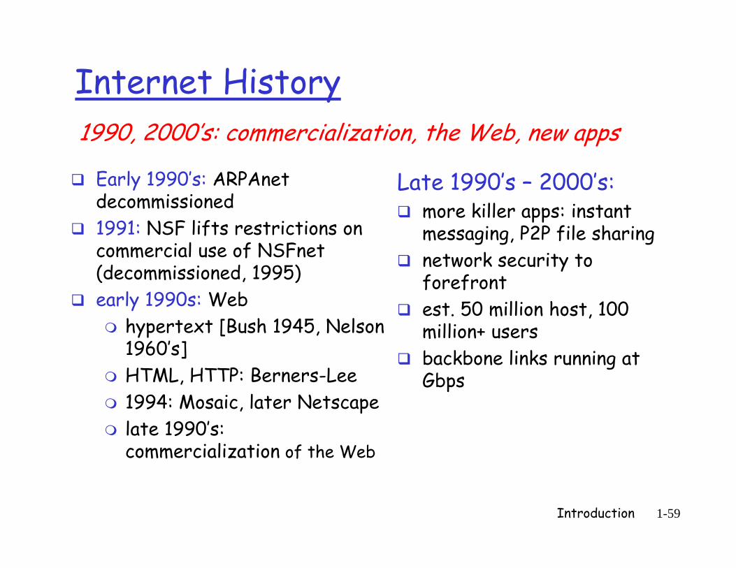
Early 1990’s: ARPAnet L t 1990’ 2000’
1990, 2000’s: commercialization, the Web, new apps
Early 1990 s: ARPAnet decommissioned1991: NSF lifts restrictions on commercial use of NSFnet
Late 1990’s – 2000’s:more killer apps: instant messaging, P2P file sharing
commercial use of NSFnet (decommissioned, 1995)early 1990s: Web
h t t [B h 1945 N l
network security to forefrontest. 50 million host, 100
hypertext [Bush 1945, Nelson 1960’s]HTML, HTTP: Berners-Lee
million+ usersbackbone links running at Gbps
1994: Mosaic, later Netscapelate 1990’s: commercialization of the Web
p
Introduction 1-59

Introduction: SummaryIntroduct on SummaryCovered a “ton” of material! You now have:
Internet overviewwhat’s a protocol?network edge core access
context, overview, “feel” of networkingmore depth detail to network edge, core, access
networkpacket-switching versus i i i hi
more depth, detail to follow!
circuit-switchingInternet/ISP structureperformance: loss delayperformance: loss, delaylayering and service modelshi t
Introduction 1-60
history