COMPUTER NETWOKRS Network fundamentals -...
55
Pag. 1 COMPUTER NETWOKRS – Network fundamentals COMPUTER NETWORKS – Network fundamentals - 1 Copyright Gruppo Reti – Politecnico di Torino Network fundamentals Gruppo Reti TLC [email protected] http://www.telematica.polito.it/ COMPUTER NETWORKS – Network fundamentals - 2 Copyright • Quest’opera è protetta dalla licenza Creative Commons NoDerivs- NonCommercial. Per vedere una copia di questa licenza, consultare: http://creativecommons.org/licenses/nd-nc/1.0/ oppure inviare una lettera a: Creative Commons, 559 Nathan Abbott Way, Stanford, California 94305, USA. • This work is licensed under the Creative Commons NoDerivs- NonCommercial License. To view a copy of this license, visit: http://creativecommons.org/licenses/nd-nc/1.0/ or send a letter to Creative Commons, 559 Nathan Abbott Way, Stanford, California 94305, USA. Copyright Gruppo Reti – Politecnico di Torino COMPUTER NETWORKS – Network fundamentals - 3 Telecommunication chronology? • “Tele” means distant – Smoke signals? – Drums in the jungle? – Mirrors? – Flags? • Focus on moder telecommunication networks – Telephone network – Internet Copyright Gruppo Reti – Politecnico di Torino
Transcript of COMPUTER NETWOKRS Network fundamentals -...

Pag. 1
COMPUTER NETWOKRS – Network fundamentals
COMPUTER NETWORKS – Network fundamentals - 1 Copyright Gruppo Reti – Politecnico di Torino
Network fundamentals
Gruppo Reti TLC
http://www.telematica.polito.it/
COMPUTER NETWORKS – Network fundamentals - 2
Copyright
• Quest’opera è protetta dalla licenza Creative Commons NoDerivs-
NonCommercial. Per vedere una copia di questa licenza, consultare:
http://creativecommons.org/licenses/nd-nc/1.0/
oppure inviare una lettera a:
Creative Commons, 559 Nathan Abbott Way, Stanford, California
94305, USA.
• This work is licensed under the Creative Commons NoDerivs-
NonCommercial License. To view a copy of this license, visit:
http://creativecommons.org/licenses/nd-nc/1.0/
or send a letter to
Creative Commons, 559 Nathan Abbott Way, Stanford, California
94305, USA.
Copyright Gruppo Reti – Politecnico di Torino
COMPUTER NETWORKS – Network fundamentals - 3
Telecommunication chronology?
• “Tele” means distant
– Smoke signals?
– Drums in the jungle?
– Mirrors?
– Flags?
• Focus on moder telecommunication
networks
– Telephone network
– Internet
Copyright Gruppo Reti – Politecnico di Torino
Pag. 2
COMPUTER NETWOKRS – Network fundamentals
COMPUTER NETWORKS – Network fundamentals - 4
Telephone network: chronology
• 1837: Morse code
• 1876: Bell phone patent
• 1891: Strowger selector patent
• 1894: First electromechanical telephone
exchange
• 1895: Marconi radio experiments
• 1923: first automatic (electromechanical)
long-distance service (Baviera - Siemens)
Copyright Gruppo Reti – Politecnico di Torino
COMPUTER NETWORKS – Network fundamentals - 5
Telephone network: chronology
• 1938: relè
• 1960: telephone exchange electronically
controlled
• 1964: first exchange fully electronic controlled
(Succasunna - USA)
• 1975: first exchange fully electronic (Chicago)
• 1980: common channel signalling, ISDN,
analog mobile networks
• 1990: Intelligent network (signalling), digital
mobile networks Copyright Gruppo Reti – Politecnico di Torino
COMPUTER NETWORKS – Network fundamentals - 6
Data networks: chronology
• 1969: ARPANET (primo RFC: Host software)
• 1971: ARPANET: 15 nodes e 23 host. E-mail
• 1973: First FTP version
• 1973: First TCP version
• 1976: Ethernet and X.25
• 1980: OSI
• 1982: Token ring (IBM)
• 1982: TCP and IP are defined as the
reference protocols (since 1/1/83) Copyright Gruppo Reti – Politecnico di Torino

Pag. 3
COMPUTER NETWOKRS – Network fundamentals
COMPUTER NETWORKS – Network fundamentals - 7
Data networks: chronology
• 1984: DNS
• 1985: FDDI
• 1990: Tim Berners-Lee (CERN) presents a
document (nobody cares) on Hypertext
Information Management. The project name
must be chosen: “Information Mine”,
“Information Mesh” ,“World Wide Web”
• 1993: Web traffic is1% of total Internet traffic
Copyright Gruppo Reti – Politecnico di Torino
COMPUTER NETWORKS – Network fundamentals - 8
Data networks: chronology
• 1997: Internet2, new network for
experimental research
• 1999: peer-to-peer applications to exchange
file file (MP3, video) directly among users (no
server intereaction): Napster, Gnutella,
Kazaa
• Since then most of the novelties in the
application side (Social networks, Streaming,
On-line gaming, P2P TV)
• Today: you know better than us Copyright Gruppo Reti – Politecnico di Torino
COMPUTER NETWORKS – Network fundamentals - 9 Copyright Gruppo Reti – Politecnico di Torino
TLC networks:
services and functions
Gruppo Reti TLC
http://www.telematica.polito.it/

Pag. 4
COMPUTER NETWOKRS – Network fundamentals
COMPUTER NETWORKS – Network fundamentals - 10 Copyright Gruppo Reti – Politecnico di Torino
Some definitions
• Taken from the CCITT “Blue Book”
(Reccomendation I.112)
– CCITT: The International Telegraph and Telephone
Consultative Committee of Telecommunication Union
(ITU).
– Since 1994 CCITT become ITU-T
COMPUTER NETWORKS – Network fundamentals - 11 Copyright Gruppo Reti – Politecnico di Torino
ITU-T
• Communication: information transfer according to
pre-established rules.
– Agreement
• Telecommunication: trasmission and reception of
signale representing signs, text, images, sounds,
info of any nature, via cables, radio, optical or
electromagnetics media
COMPUTER NETWORKS – Network fundamentals - 12 Copyright Gruppo Reti – Politecnico di Torino
Example
• Telephones are user terminals connected to a
network providing telecommunication services
TLC
NETWORK

Pag. 5
COMPUTER NETWOKRS – Network fundamentals
COMPUTER NETWORKS – Network fundamentals - 13 Copyright Gruppo Reti – Politecnico di Torino
ITU-T: definitions
• Telecommunication service: offered from a public
or private provider to his customers to satisfy a
specific telecommunication need
• Functions in a telecommunication network:
operations internally executed in a network to
provide services to users
COMPUTER NETWORKS – Network fundamentals - 14
Functions: an example
• By raising the handset the user signals to the
network that he is willing to start the call
procedure
Copyright Gruppo Reti – Politecnico di Torino
COMPUTER NETWORKS – Network fundamentals - 15
Functions: an example
• The user waits for the free tone from the
central office
Copyright Gruppo Reti – Politecnico di Torino
TU - TU

Pag. 6
COMPUTER NETWOKRS – Network fundamentals
COMPUTER NETWORKS – Network fundamentals - 16
Functions: an example
• The user dials the number to signal to the
network the user (more precisely the user
terminal) he/she is willing to be connected to
Copyright Gruppo Reti – Politecnico di Torino
00390118935649
(not my phone number!)
COMPUTER NETWORKS – Network fundamentals - 17
Functions: user signalling
• Control information transfer between the user
and the network
• SIGNALLING.
Copyright Gruppo Reti – Politecnico di Torino
COMPUTER NETWORKS – Network fundamentals - 18
ITU-T definition
• Signalling: exchange of control information
associated with the setup and release of a
telephone call on a telecommunications
circuit.
• Example of this control information:
– digits dialed by the caller
– the caller's billing number
– call-related information
• Actions order is important
• Time is important Copyright Gruppo Reti – Politecnico di Torino

Pag. 7
COMPUTER NETWOKRS – Network fundamentals
COMPUTER NETWORKS – Network fundamentals - 19 Copyright Gruppo Reti – Politecnico di Torino
Functions: switching
• The network identifies resources needed to
connect the two users
• In the case of telephone networks, a circuit is
established. Circuit switching.
COMPUTER NETWORKS – Network fundamentals - 20
ITU-T definition
• Switching: the process of interconnecting
functional units, transmission channel or
telecommunication circuits for the time
needed to transfer signals
Copyright Gruppo Reti – Politecnico di Torino
COMPUTER NETWORKS – Network fundamentals - 21
Functions: network signalling
• To execut the switching function, i.e., to build
a circuit
– Nodes need to exchange control information
(e.g. callee phone number)
– Information exchange within the network is
needed
– Network signalling
Copyright Gruppo Reti – Politecnico di Torino

Pag. 8
COMPUTER NETWOKRS – Network fundamentals
COMPUTER NETWORKS – Network fundamentals - 22
Functions: an example
• In the early, roaring years of telephony
– signalling was voice based
– switching was manual
Copyright Gruppo Reti – Politecnico di Torino
COMPUTER NETWORKS – Network fundamentals - 23 Copyright Gruppo Reti – Politecnico di Torino
Functions: an example
• In the early, roaring years of telephony
– signalling was voice based
– switching was hand based
COMPUTER NETWORKS – Network fundamentals - 24 Copyright Gruppo Reti – Politecnico di Torino
Functions: an example
• In the early, roaring years of telephony
– signalling was voice based
– switching was hand based

Pag. 9
COMPUTER NETWOKRS – Network fundamentals
COMPUTER NETWORKS – Network fundamentals - 25
Functions: transmission
• The two users can (happily?) exchange
information
Copyright Gruppo Reti – Politecnico di Torino
Hi, how are
You doing?
I was fine
COMPUTER NETWORKS – Network fundamentals - 26 Copyright Gruppo Reti – Politecnico di Torino
ITU-T definition
• Transmission: signal transfer from one point to
one or several points
COMPUTER NETWORKS – Network fundamentals - 27 Copyright Gruppo Reti – Politecnico di Torino
Functions: an example
• When the call is ended, the circuit is
released (to free network resources)

Pag. 10
COMPUTER NETWOKRS – Network fundamentals
COMPUTER NETWORKS – Network fundamentals - 28 Copyright Gruppo Reti – Politecnico di Torino
Functions: management
• Connecting new users
• Adding channels or nodes
• Upgrade or substitute devices (to follow technological evolution)
• Reconfiguration after fault
• Performance monitoring
• Device control
COMPUTER NETWORKS – Network fundamentals - 29
Functions in a TLC network
• Signalling (implies routing)
• Switching (implies routing)
• Transmission
• Management
• And many others ….
Copyright Gruppo Reti – Politecnico di Torino
COMPUTER NETWORKS – Network fundamentals - 30 Copyright Gruppo Reti – Politecnico di Torino
Network Topologies
Gruppo Reti TLC
http://www.telematica.polito.it/

Pag. 11
COMPUTER NETWOKRS – Network fundamentals
COMPUTER NETWORKS – Network fundamentals - 31
Network
• Definition:
– A set of nodes and channels that offer a
connectionamong two or more points to make
telecommunication possible
• Node is the point where switching occurs
• Channel is any communication media
– The channel may be
• Monodirectional (one way)
• Bidirectional
Copyright Gruppo Reti – Politecnico di Torino
COMPUTER NETWORKS – Network fundamentals - 32
Type of channels
• Point-to-point channel
• Only two nodes connected to channel end
points
• The channel is used by both nodes in the
same fashion
Copyright Gruppo Reti – Politecnico di Torino
A B
COMPUTER NETWORKS – Network fundamentals - 33
Type of channels
• Multipoint channel
• Several nodes connectes to a single chanel
• One master and several slaves
Copyright Gruppo Reti – Politecnico di Torino
Slave
Master

Pag. 12
COMPUTER NETWOKRS – Network fundamentals
COMPUTER NETWORKS – Network fundamentals - 34
Type of channels
• Broadcast channel
• Single communication channel shared by all
nodes
– This room!
• The information sent by one node is received
by all other users
• Data should contain the destination address
– YOU pay attention!
Copyright Gruppo Reti – Politecnico di Torino
COMPUTER NETWORKS – Network fundamentals - 35
Topologies in TLC networks
• The network topology is defined by the
relative position of nodes and channels
• A network topology is a graph G=(V,A)
– V = set of vertices (represented as circles -
nodes)
– A = set of edges (represented as segments -
channels)
Copyright Gruppo Reti – Politecnico di Torino
COMPUTER NETWORKS – Network fundamentals - 36 Copyright Gruppo Reti – Politecnico di Torino
Topologies in TLC networks
• Edges may be:
– direct (directed segments (arrow) – unidirectional
channels)
– Undirect (non directed segmetns – bidirectional
channels)
• Define:
– N= |V|
– C= |A|

Pag. 13
COMPUTER NETWOKRS – Network fundamentals
COMPUTER NETWORKS – Network fundamentals - 37 Copyright Gruppo Reti – Politecnico di Torino
Fully meshed topology
• C = N(N-1)/2
• Advantage: highly fault tolerant (many paths available among pair of nodes)
• Disadvantage: too many channels needed
• Many alternative paths, but only one shortest path (one hop)
• There is an obvious, minimunm distance, routing choice
• Used only when N is small (e.g., core nodes in a national telephone network)
A
E B
C D
COMPUTER NETWORKS – Network fundamentals - 38 Copyright Gruppo Reti – Politecnico di Torino
Tree topology
• C = N -1
• Disadvantage: fault vulnerable (only one path exist for any node pair)
• Advantage: smallest possible number of channels for a connected topololgy
• Used to reduce cost
• No routing alternatives
A
E B
C D
COMPUTER NETWORKS – Network fundamentals - 39 Copyright Gruppo Reti – Politecnico di Torino
Active star topology
• C = N (star centre is not a node, used only to enable communication)
• Disadvantage: vulnerability to faults on the star centre
• Advantage: low number of channels
• Used to keep cost under control
• Each node has a unique routing
• All routing complexity in the star centre
• Used – in LANs (switch)
– in satellite networks (satellite)
– in cellulare mobile networks (base station)
A
E B
C D

Pag. 14
COMPUTER NETWOKRS – Network fundamentals
COMPUTER NETWORKS – Network fundamentals - 40 Copyright Gruppo Reti – Politecnico di Torino
Passive star topology
• C = 1 (even if N wires)
• The star node passively propagates signals on any wire
• Broadcast channel
• Disadvantage: vulnerable to star center fault
• Advantage: small number of channels
• Low cost
• Each node has a unique routing • Used
– in LANs (hub)
– in distribution networks (reflector)
A
E B
C D
COMPUTER NETWORKS – Network fundamentals - 41 Copyright Gruppo Reti – Politecnico di Torino
Meshed topology
• N-1 < C < N(N-1)/2
• Not a regular topology
• Advantage: fault tolerance and
number of channels can be traded
off
• Complex routing: many alternative
(good) paths
• Most commonly used (Internet,
telephone)
A
E B
C D
COMPUTER NETWORKS – Network fundamentals - 42 Copyright Gruppo Reti – Politecnico di Torino
Ring topology
• Can be unidirectional or biderectional

Pag. 15
COMPUTER NETWOKRS – Network fundamentals
COMPUTER NETWORKS – Network fundamentals - 43 Copyright Gruppo Reti – Politecnico di Torino
Ring topology
• C=N/2 for the unidirectional ring
• C=N for te bidirectional ring
• Used in LAN and MAN but also to build meshed topologies (SDH)
• Two alternative paths for each node pair
COMPUTER NETWORKS – Network fundamentals - 44
Ring topology
• In case of faults, the bidirectional ring
ensures network survivability (with reduced
capacity)
• The bidirectional ring is the simplest topology
that provides an alternative path in case of
faults
Copyright Gruppo Reti – Politecnico di Torino
COMPUTER NETWORKS – Network fundamentals - 45 Copyright Gruppo Reti – Politecnico di Torino
Bus topology
• C=N-1 for the active bus (peculiar tree)
• C=1 for the passive bus (broadcast channel)
• Only one path for any pair of nodes
• Used in LANs
A
E B
C D

Pag. 16
COMPUTER NETWOKRS – Network fundamentals
COMPUTER NETWORKS – Network fundamentals - 46 Copyright Gruppo Reti – Politecnico di Torino
Physical and logical topology
• It is important to distinguish between the
physical and logical topology
– Logical topology: logical interconnection among
nodes via channels
– Physical topology: takes into account transmission
media constraints
COMPUTER NETWORKS – Network fundamentals - 47 Copyright Gruppo Reti – Politecnico di Torino
Physical topology
A B
C D
COMPUTER NETWORKS – Network fundamentals - 48 Copyright Gruppo Reti – Politecnico di Torino
Logical topology
A B
C D

Pag. 17
COMPUTER NETWOKRS – Network fundamentals
COMPUTER NETWORKS – Network fundamentals - 49 Copyright Gruppo Reti – Politecnico di Torino
Topologies and performance
• The amount of traffic that can be succesfully
transferred (throughput) in a network is
– for a given channel available capacity
– inversely proportional to the average distance
among node pairs
– weighted by the amount of traffic exchanged
between the two node
• For uniform traffic and regular topologies the
average distance on the topology establish the
throughput
COMPUTER NETWORKS – Network fundamentals - 50 Copyright Gruppo Reti – Politecnico di Torino
Topologies and performance
• Comparison among topologies, with the same
number of nodes (4) and (almost) the same
number of channels
• Uniform traffic
– Every node pair exchange x bit/s. Total generated
traffic is 12x.
• Every unidirectional channel has capacity B bit/s.
• Compute: average distance, network capacity
(maximum throughput), maximum channel
load,maximum node load
COMPUTER NETWORKS – Network fundamentals - 51
Topologies and performance
• Capacity: 3x2B=6B
• Average distance: 20/12=1.66
• Consider only traffic from left to right (simmetry)
– maximum channel load is 4x. Thus, x <= B/4
• Node 3 (or 2) must handle 7B/4 of traffic unit
• Uniform traffic, non regular topology, unbalanced
channel load, unbalanced node load
Copyright Gruppo Reti – Politecnico di Torino
1 2 3 4 3x 2x
2x
x
x
x

Pag. 18
COMPUTER NETWOKRS – Network fundamentals
COMPUTER NETWORKS – Network fundamentals - 52 Copyright Gruppo Reti – Politecnico di Torino
Topologies and performance • Capacity: 3x2B=6B
• Average distance: 1.5
• Considering the traffic from node 4.
– Maximum load on (all) channel is 3x. Thus x <=B/3
– The same holds for the other direction
• Node 4 must handle 3B of traffic unit
• Uniform traffic, non regular topology, balanced channel load,
unbalanced node load
x
x
x
x
x
x x
x
x 1 2
4
3
COMPUTER NETWORKS – Network fundamentals - 53 Copyright Gruppo Reti – Politecnico di Torino
Topologies and performance • Capacity: 4x2B=8B
• Average distance: 1.33
• For clockwise traffic the maximum channel load is 2x. Thus x <=
B/2.
– The same holds for counter clock wise traffic
• Each node must handle 2B unit of traffic
• Uniform traffic, regular topology, balanced channel load, balanced
node load 3x/2
x/2
3x/2
x/2 3x/2
x/2
3x/2
x/2
COMPUTER NETWORKS – Network fundamentals - 54 Copyright Gruppo Reti – Politecnico di Torino
Topologies: average distance
Manhattan
E[d2] =O(N)
E[d1]> E[d2] >E[d3]
Ring
E[d1]=O(N) Shuffle
E[d3]=O(logN)

Pag. 19
COMPUTER NETWOKRS – Network fundamentals
COMPUTER NETWORKS – Network fundamentals - 55 Copyright Gruppo Reti – Politecnico di Torino
TLC networks: services
Gruppo Reti TLC
http://www.telematica.polito.it/
COMPUTER NETWORKS – Network fundamentals - 56 Copyright Gruppo Reti – Politecnico di Torino
ITU-T: definition
• Telecommunication service: offered from a public
or private provider to his customers to satisfy a
specific telecommunication need
COMPUTER NETWORKS – Network fundamentals - 57
Integrated vs dedicated networks
• TLC networks can be:
– Dedicated (to a specific service)
• Telephone
• TV distribution
• Internet (in the early days)
– Integrated (several services)
• Narrowband ISDN o N-ISDN
• Broadband ISDN o B-ISDN
• Internet (today)
Copyright Gruppo Reti – Politecnico di Torino

Pag. 20
COMPUTER NETWOKRS – Network fundamentals
COMPUTER NETWORKS – Network fundamentals - 58
TLC service taxonomy
• Bearer service
– Permits transmission of information between network
interfaces. These services give the subscriber the
capacity required to transmit appropriate signals between
certain access points, i.e. user network interfaces.
– Example: Point to point direct circuit
• Teleservices
– provide the full capacity for communications by means of
terminaland network functions and possibly functions
provided by dedicated centers.
– Examples: phone calls, telefax
– Classified in base services or supplementary services
Copyright Gruppo Reti – Politecnico di Torino
COMPUTER NETWORKS – Network fundamentals - 59
Teleservices
• Base service
– provides minimal functionalities needed by the
service itself
– Examples:
• POTS (phone calls)
• Television
Copyright Gruppo Reti – Politecnico di Torino
COMPUTER NETWORKS – Network fundamentals - 60
Teleservices
• Supplementary service
– Provides to the user additional functionalities
with respect to the base service
– Can be offered only together with a base service
– Modifies or extends a base service
• Examples
– Telephone networks: call waiting alert, toll free
number, automatic redial, answsering machine
– Television: Video-on-Demand (VOD)
Copyright Gruppo Reti – Politecnico di Torino

Pag. 21
COMPUTER NETWOKRS – Network fundamentals
COMPUTER NETWORKS – Network fundamentals - 61 Copyright Gruppo Reti – Politecnico di Torino
Teleservices: information flow
• Information flows can be:
– Symmetric bidirectional
• Phone calls
– Asymmetric bidirectional
• ADSL
– Monodirectional
• TV distribution
• Information flow can be:
– Point to point
• Phone calls
– Point to multipoint
• Multimedia streaming
– Multipoint to multipoint
• Teleconference
COMPUTER NETWORKS – Network fundamentals - 62
Teleservices taxonomy
• Should be taken with some care like any
taxonomy
• Interactive
– conversational
– messaging
– searching/retrieval
• Diffusive
– With or withouth presentation control from the
user
Copyright Gruppo Reti – Politecnico di Torino
COMPUTER NETWORKS – Network fundamentals - 63 Copyright Gruppo Reti – Politecnico di Torino
Conversational interactive
teleservices • End to end data transfer in real time
• Examples (video, voice)
– Phone calls
– Videoconference
– Videosurveillance
• Examples (data)
– File trasnfer
– Computer interconnection
– Real time control
– Multiplayer games

Pag. 22
COMPUTER NETWOKRS – Network fundamentals
COMPUTER NETWORKS – Network fundamentals - 64 Copyright Gruppo Reti – Politecnico di Torino
Messaging interactive teleservices
• End to end communication exploiting
intermediate devices for information storage
• Examples (video, voice)
– Answering machine
– Image transfer
• Examples (data)
– SMS
COMPUTER NETWORKS – Network fundamentals - 65
Searching/retrieval
interactive teleservices • Permits user to search/retrieve information
stored in public data base
• Examples:
– Web
– Teleteaching
– Telesoftware
– Teleshopping
Copyright Gruppo Reti – Politecnico di Torino
COMPUTER NETWORKS – Network fundamentals - 66 Copyright Gruppo Reti – Politecnico di Torino
Diffusive teleservices without
presentation control
• The information flow is distributed from a source
to a set of receivers (authorization may be
required)
• Users cannot control information flow (starting
time, presentation order, etc)
• Examples
– TV
– pay TV
– radio

Pag. 23
COMPUTER NETWOKRS – Network fundamentals
COMPUTER NETWORKS – Network fundamentals - 67
Diffusive teleservices without
presentation control • The information flow is distributed from a
source to a set of receivers (authorization may be required)
• Information is organized in sequences that are cyclically repeated
• Users may select starting time and/or presentation ordering
• Examples
– televideo
– near VoD
Copyright Gruppo Reti – Politecnico di Torino
COMPUTER NETWORKS – Network fundamentals - 68 Copyright Gruppo Reti – Politecnico di Torino
How to provide teleservices?
• Two (Internet derived) models
– client-server
– peer-to-peer
• Can be distinguished looking at how user
application software is behaving
COMPUTER NETWORKS – Network fundamentals - 69 Copyright Gruppo Reti – Politecnico di Torino
Client-server model
• Two clearly different roles
– Client • start interaction with the server (“talks first”), asking for a
service (es. web page, e-mail transfer)
– Server • provdes the requested service to the client( sned the web
page, receives and stores e-mails)
• Idle while waiting for clients
• Most of the time (not always) the information is stored in the server
• Most of Internet applications follow the client server model

Pag. 24
COMPUTER NETWOKRS – Network fundamentals
COMPUTER NETWORKS – Network fundamentals - 70
Client-server models
• Servers
– are activated when the device hosting them is
switched
– Wait for client requestsa
– Always available
• Clients
– Activated when the user requires a service
– After the service has been provided they are de-
activated
Copyright Gruppo Reti – Politecnico di Torino
COMPUTER NETWORKS – Network fundamentals - 71 Copyright Gruppo Reti – Politecnico di Torino
request
reply
Client-server model
COMPUTER NETWORKS – Network fundamentals - 72 Copyright Gruppo Reti – Politecnico di Torino
Peer-to-peer model
• Introduced more recently in the Internte
• Phone calls, fax follow a similar model
• Mainly used for interaction among large groups
of users
• All applications are peers
• Information distributed and shared among all
peers

Pag. 25
COMPUTER NETWOKRS – Network fundamentals
COMPUTER NETWORKS – Network fundamentals - 73 Copyright Gruppo Reti – Politecnico di Torino
Transmission techniques
in networks
Gruppo Reti TLC
http://www.telematica.polito.it/
COMPUTER NETWORKS – Network fundamentals - 74
Types of transmission
• Analog transmission
– Information is transferred via a signal
• continuous
• limited
• assuming infinite possible values
• Digitral transmission
– Information is transferred via a signal
• Not continuous
• limited
• assuming a finite set of possible values
Copyright Gruppo Reti – Politecnico di Torino
COMPUTER NETWORKS – Network fundamentals - 75 Copyright Gruppo Reti – Politecnico di Torino
t
Analog transmission

Pag. 26
COMPUTER NETWOKRS – Network fundamentals
COMPUTER NETWORKS – Network fundamentals - 76 Copyright Gruppo Reti – Politecnico di Torino
t
Digital transmission
COMPUTER NETWORKS – Network fundamentals - 77 Copyright Gruppo Reti – Politecnico di Torino
From analog to digital
t t
Sampling process
t
Quantization process
Analog signal
t
Digital signal 1010
1001
1000
0111
0110
0101
0100
0011
0010
0001
0000
1010
1001
1000
0111
0110
0101
0100
0011
0010
0001
0000
0011 – 0011 – 0100 – 0100 – 0100 – 0100 – 0010 - 0010
COMPUTER NETWORKS – Network fundamentals - 78
From digital to analog
• If the analog signal is bandwidth limited and
the signal bandwidth is B
– The sampling process is lossless (from the
samples the original signal can be exactly
rebuild) if samling at a frequency 2B
• The quantization process is lossy
– Quantization error
• By selecting a proper number of levels, the
quantization error can be controlled a priori
Copyright Gruppo Reti – Politecnico di Torino

Pag. 27
COMPUTER NETWOKRS – Network fundamentals
COMPUTER NETWORKS – Network fundamentals - 79 Copyright Gruppo Reti – Politecnico di Torino
Type of tranmissions
• Analog
– Information, assuming values in a continuous set, is
represented as a continuos variation of an electrical/optical
parameter
• Digital
– Information is represented as an electrical/optical parameter
assuming a set of finite values (discrete)
– However, signals are physically continuos!
– So, where is the difference?
– In the receiver!
• The receiver makes a decision process and tries to rebuild the discrete
information
• Clock synchronization is critical
COMPUTER NETWORKS – Network fundamentals - 80
Parallel vs serial tranmission
• Parallel
– Information is transferred in parallel over a
communication bus (in a computer 8 bit=1byte in parallel)
or on a serial line or through several parallel wires.
Clock (synchronization) signals are sent together with
data to align receiver clock to transmitter clock
• Serial
– Information is sent bit by bit on the channel.
Synchronization mechanism are adopted between the
transmitter and the receiver
– More common in networks
Copyright Gruppo Reti – Politecnico di Torino
COMPUTER NETWORKS – Network fundamentals - 81 Copyright Gruppo Reti – Politecnico di Torino
1
0
0
0
1
1
1
1
0
0
0
1
1
0
1
1
Bit 1
Bit 8
Parallel
Parallel transmission

Pag. 28
COMPUTER NETWOKRS – Network fundamentals
COMPUTER NETWORKS – Network fundamentals - 82 Copyright Gruppo Reti – Politecnico di Torino
1 0 1 0 0 1 1 1 0 0 1 1 1 0 0 1
Serial transmission
COMPUTER NETWORKS – Network fundamentals - 83 Copyright Gruppo Reti – Politecnico di Torino
Serial transmission
• Asynchronous
– Every information byte (or packet) is transmitted
separately. The reception clock must be
synchronized to the transmitter clock on any data to
compensate for clock skew
• Synnchronous
– Data to be sent are structured in frames. Transmitter
and receiver clock are continuously synchronized to
ensure that bit detection is correct also at high bit
rate
COMPUTER NETWORKS – Network fundamentals - 84 Copyright Gruppo Reti – Politecnico di Torino
Asynchronous transmission
• S: Start Bit
• P: Parity Bit
• Stop Bits: 1, 1.5, 2
LSB P MSB STOP
BITS S LINE
IDLE
FROM 5 TO 8 BIT
1 CHARACTER

Pag. 29
COMPUTER NETWOKRS – Network fundamentals
COMPUTER NETWORKS – Network fundamentals - 85 Copyright Gruppo Reti – Politecnico di Torino
Synchronous trasmission
• Synchronization overhead is reduced
LSB MSB
CHARATER N
MSB LSB
CHARACTER N-1 CHARACTER N+1
CLOCK
COMPUTER NETWORKS – Network fundamentals - 86 Copyright Gruppo Reti – Politecnico di Torino
Reception
• Continuous reception on point-to-point
channels for synchronous transmissione
– Easier to keep clock synchronized
• Burst mode reception
– Ove broadcast or multi-point channels
synchronous transmission is not possible (many
transmitters schare che channel)
– Receiver must adapt is clock to different
transmitters for any data send over the channel
COMPUTER NETWORKS – Network fundamentals - 87 Copyright Gruppo Reti – Politecnico di Torino
Transfer modes in networks
Gruppo Reti TLC
http://www.telematica.polito.it/
Pag. 30
COMPUTER NETWOKRS – Network fundamentals
COMPUTER NETWORKS – Network fundamentals - 88
Sharing channel resources
• Sharing of channel resources among data flows comes in two different flavours – Multiplexing
• All flows access the channel from a single point
• Single transmitter scenario
• Centralized problem
• A radio access from an antenna (base station in a cellular network, access point in a WI-FI network, satellite transmission), an output link in a switch or a router
– Multiple-access • Flows access the channel from different access points
• Many transmitters are active
• Distributed problems
• Local area networks (if not switched), mobile phones in a cellulare network, PC accessing via a Wi-FI hot-spot
COMPUTER NETWORKS – Network fundamentals - 89
Sharing channel resources
• Sharing of channel resources among data blonging to several flows comes in two different flavours – Multiplexing
• All flows access the channel from a single point
• Single transmitter scenario
• Centralized problem
• A radio access from an antenna (base station in a cellular network, access point in a WI-FI network, satellite transmission), an output link in a switch or a router
– Multiple-access • Flows access the channel from different access points
• Many transmitters are active
• Distributed problems
• Local area networks (if not switched), mobile phones in a cellulare network, PC accessing via a Wi-FI hot-spot
– Multiple access is a more complex task
COMPUTER NETWORKS – Network fundamentals - 90
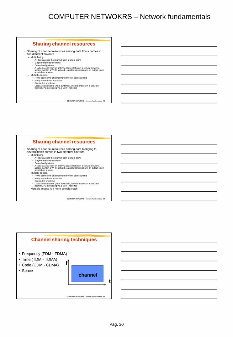
Channel sharing techniques
• Frequency (FDM - FDMA)
• Time (TDM - TDMA)
• Code (CDM - CDMA)
• Space
t
f
channel

Pag. 31
COMPUTER NETWOKRS – Network fundamentals
COMPUTER NETWORKS – Network fundamentals - 91 Copyright Gruppo Reti –
Politecnico di Torino
Frequency division
• Each flow is transmitted using different frequency bands
• Need for band guard
• Filters needed to receive the proper channel
f
t
COMPUTER NETWORKS – Network fundamentals - 92
Time division (TDM – TDMA)
• Each flow exploits different time intervals (slots)
• Define frame over which slot allocations are repeated
• Each frame last 125 us
• Need for time guard
• Need to know
the proper time slots
for reception
f
t
COMPUTER NETWORKS – Network fundamentals - 93
Code division
(CDM – CDMA) • Each flow exploits a different code (waveform
with higher frequency than the bit tx rate)
• Need for orthogonal codes
• Code is not a
new dimension c
t
f

Pag. 32
COMPUTER NETWOKRS – Network fundamentals
COMPUTER NETWORKS – Network fundamentals - 94 Copyright Gruppo Reti –
Politecnico di Torino
Code division
(CDM – CDMA) • Code is not a subset of frequencies and/or a
a set of timeslots
f
t
COMPUTER NETWORKS – Network fundamentals - 95 Copyright Gruppo Reti – Politecnico di Torino
CDMA • Data flows separated using orthogonal codes
• Neither time nor frequency separation
• Better noise protection
• Transmission: scalar product of data signal and of the transmitter code signal
• Reception: scalar product of data signal and of the transmitter code signal (must be known)
COMPUTER NETWORKS – Network fundamentals - 96
Code division
• Example
– Code word used bu user i: +1 +1 -1 -1
– Coded sequence = information bit x code word
– Information bit: -1 -1 1 1 -1
– Coded sequence: -1-1+1+1 -1-1+1+1 +1+1-1-1 +1+1-1-1 -1-1+1+1

Pag. 33
COMPUTER NETWOKRS – Network fundamentals
COMPUTER NETWORKS – Network fundamentals - 97
Code multiplexing
• Example:
– Code word for user 1: +1 +1 -1 -1
– Code word for user 2: +1 +1 +1 +1
– Code word for user 3: +1 -1 +1 -1
– Code word for user 4: +1 -1 -1 +1
• Over the channel, transmitted signals sum up
(need to equalize power)
– Transmissions of 1+2+3: +3 +1 +1 -1
– Transmissions of 2+3: +2 0 +2 0
COMPUTER NETWORKS – Network fundamentals - 98
Code multiplexing
• Un esempio (segue):
– Reception = correlation with code words
– Reception of user 1 = scalar product of the received sequence with the code word +1 +1 -1 -1
– Transmissions of 1+2+3: +3 +1 +1 -1
– Correlation with +1 +1 - 1 -1 = 4
– Transmissions of 2+3: +2 0 +2 0
– Correlation with +1 +1 -1 -1 = 0
COMPUTER NETWORKS – Network fundamentals - 99
Space multiplexing
• Networks exploit also space multiplexing
• First idea is to use multiple parallel wires
• Routing techniques may also try to exploit space
multiplexing to increase network capacity
– Cell in wireless access are an example of space
reuse

Pag. 34
COMPUTER NETWOKRS – Network fundamentals
COMPUTER NETWORKS – Network fundamentals - 100 Copyright Gruppo Reti –
Politecnico di Torino
Multiplexing or multiple access
• Time, frequency, code and space (multiple wires)
are all equivalente alternatives
– Given a channel capacity we can choose one among
the above techniques depending on technological
constraints
• Code division permits to “increase” channel
capacity (allowing more users) if using pseudo-
orthogonal codes but degrading the signal to
noise ratio at the receiver (increase the bit error
rate)
COMPUTER NETWORKS – Network fundamentals - 101
Statistical multiplexing
• Multiplexing can be
– deterministic, fixed in time, on the basis of
requirements determined at connection setup
– statistical, variable in time, to adapt to
instantaneous traffic requirements
COMPUTER NETWORKS – Network fundamentals - 102
Statistical Multiplexing
• Sequence of A & B packets does not have
fixed pattern, bandwidth shared on demand
• Dynamic TDM scheme
A
B
C 100 Mb/s Ethernet
1.5 Mb/s
D E
statistical multiplexing
queue of packets waiting for output
link

Pag. 35
COMPUTER NETWOKRS – Network fundamentals
COMPUTER NETWORKS – Network fundamentals - 103
Switching techniques
• Resource allocation process for the time
needed to transfer information on the
newtork
• Two main technique
– Circuit switching
• Useful for continuous, regular flows
• Voice on a telephone network
– Packet (and cell) switching
• Useful for bursty, unpredictable flows
• Data transmission on Internret
Copyright Gruppo Reti – Politecnico di Torino
COMPUTER NETWORKS – Network fundamentals - 104 Copyright Gruppo Reti – Politecnico di Torino
Circuit switching
• Resources are allocated on demand (through
signalling) to each user call to create a circuit
• A circuit is (or is equivalent to) a physical link
directly connecting the two user terminals
COMPUTER NETWORKS – Network fundamentals - 105 Copyright Gruppo Reti – Politecnico di Torino
Circuit switching
• The circuit is uniquely allocated to the two users
for the whole call duration
• No other user can exploit the circuit until the call
is over
• Resources are made available at the end of the
call, when requested by one of the two users
through a signalling procedure

Pag. 36
COMPUTER NETWOKRS – Network fundamentals
COMPUTER NETWORKS – Network fundamentals - 106
Circuit switching
• Opening
• Data transfer
• Closing
U1 N1 N2 U2
t t t t
COMPUTER NETWORKS – Network fundamentals - 107
Circuit switching
• Example: telephone network
Copyright Gruppo Reti – Politecnico di Torino
1. Call request 2. Incoming call
3. Call accepted 4. Call accepetd
5. Data transmission 6.Data reception
COMPUTER NETWORKS – Network fundamentals - 108 Copyright Gruppo Reti – Politecnico di Torino
Circuit switching node architecture
Input
interface
Output
interface
Inerconnection
network
Switching
matrix
Command
system Signalling Signalling
command

Pag. 37
COMPUTER NETWOKRS – Network fundamentals
COMPUTER NETWORKS – Network fundamentals - 109
Space vs time switching
125 ms
125 ms
U1 N1 N2 U2
U1 N1 N2 U2
COMPUTER NETWORKS – Network fundamentals - 110
Circuit switching
• Advantages:
– Fixed guaranteed bit rate
– Fixed transfer delay
– Circuit transparency (format, speed, protocol)
• Changing the user terminals is enouigh to change
application
– Negligible delays in crossing nodes
Copyright Gruppo Reti – Politecnico di Torino
COMPUTER NETWORKS – Network fundamentals - 111
Circuit switching
• Disadvantages:
– Resources allocated to a single call
• Efficient only for non bursty (regular) flows
– Time needed to open the circuit
– No conversion of format, speed, protocols
performed by the network (e.g. no error control is
possible)
– Rate (price) time based
Copyright Gruppo Reti – Politecnico di Torino

Pag. 38
COMPUTER NETWOKRS – Network fundamentals
COMPUTER NETWORKS – Network fundamentals - 112
Packet switching
• No resource allocation
• Well suited for bursty (non regular) sources
• Similar to the mailing system
Copyright Gruppo Reti – Politecnico di Torino
P.T.
P.T.
ADDRESS
COMPUTER NETWORKS – Network fundamentals - 113 Copyright Gruppo Reti – Politecnico di Torino
Packet switching
• Data to be sent are organized in packets, (PDU)
including user data and control information
• PDU = protocol data unit
• PCI = protocol control information (control)
• SDU = service data unit (user data)
PCI SDU
COMPUTER NETWORKS – Network fundamentals - 114
Packet switching
• Data unit is the ISO definition.
• Other names :
– Packet
– Cella (fixed size data unit)
– Datagram
– Segment
– Message
– Frame
Copyright Gruppo Reti – Politecnico di Torino
Pag. 39
COMPUTER NETWOKRS – Network fundamentals
COMPUTER NETWORKS – Network fundamentals - 115
Packet switching
• Data unit are delivered to the network
• Each node
– Stores the packet while receiving it
– Process the packet to define the output channel
over which to send it (routing)
– Stores the packet in the queue for transmission
• Store and forward behaviour
– implies delays:processing, tx, rx AND queueing
Copyright Gruppo Reti – Politecnico di Torino
COMPUTER NETWORKS – Network fundamentals - 116
Store and forward
• Dominant operating mode:
– Need to read the header to execute routing
– Routing (and other processing) requires time
– Some form of header error protection is needed
– Different links may have different speed
Copyright Gruppo Reti – Politecnico di Torino
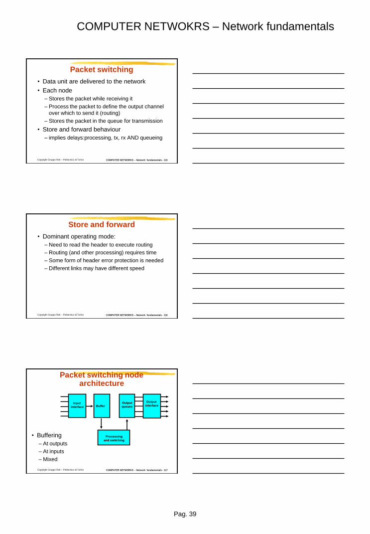
COMPUTER NETWORKS – Network fundamentals - 117 Copyright Gruppo Reti – Politecnico di Torino
Packet switching node architecture
• Buffering
– At outputs
– At inputs
– Mixed
Input
interface
Processing
and switching
Buffer Output
queues
Output
interface
Pag. 40
COMPUTER NETWOKRS – Network fundamentals
COMPUTER NETWORKS – Network fundamentals - 118
Packet switching
• It may be necesary to partition user data in
pieces due to packet size limitations
– Every packet has its own header
• Fixed vs variable packet size?
Copyright Gruppo Reti – Politecnico di Torino
PCI SDU
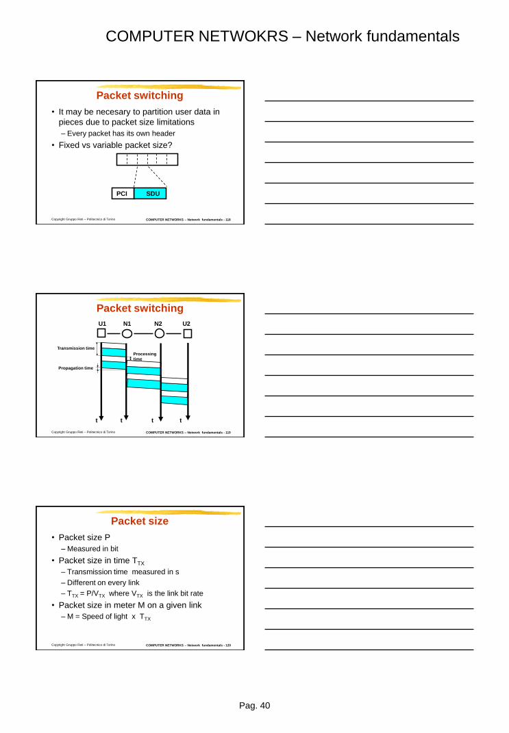
COMPUTER NETWORKS – Network fundamentals - 119 Copyright Gruppo Reti – Politecnico di Torino
Packet switching
U1 N1 N2 U2
t t t t
Transmission time
Propagation time
Processing
time
COMPUTER NETWORKS – Network fundamentals - 120
Packet size
• Packet size P
– Measured in bit
• Packet size in time TTX
– Transmission time measured in s
– Different on every link
– TTX = P/VTX where VTX is the link bit rate
• Packet size in meter M on a given link
– M = Speed of light x TTX
Copyright Gruppo Reti – Politecnico di Torino

Pag. 41
COMPUTER NETWOKRS – Network fundamentals
COMPUTER NETWORKS – Network fundamentals - 121
Delays
• Delays suffered by each packet from source to destination
node
• In each link
– Transission (and reception) delay
• It is a fiunciton of packet size in bit and of the link bit rate
– Propagation delay
• It is a function of link length in meters
• In each switching node
– Processing time
• Function of the processing speed and of the complexity of the executed
proceures on packet header
• Normallu negligible with respect to transimssion time
– Queuing delays
• Depend on the traffic generated by all users
• Highly variable Copyright Gruppo Reti – Politecnico di Torino
COMPUTER NETWORKS – Network fundamentals - 122
Packet switching
• Packet lenght depends on
– Pipelining
• Small packets increase the tranmsission
pipeline, parallel transmission on different
links of packets belonging to the same flow
– node latency (tx/rx delay) reduction
• Latency can always be reduced increasing
the link bit rate
Copyright Gruppo Reti – Politecnico di Torino
COMPUTER NETWORKS – Network fundamentals - 123
Pipelined transmission
• HP: negligible propagation and processing
delay
Copyright Gruppo Reti – Politecnico di Torino
A B C D
80 kb/s 80 kb/s 80 kb/s
10 kB
1 kB
1s + 1s + 1s = 3s
{0.1s + … + 0.1s} + 0.1s + 0.1s = 1.2s

Pag. 42
COMPUTER NETWOKRS – Network fundamentals
COMPUTER NETWORKS – Network fundamentals - 124
Pipelined transmission
• Increasing by 10 the link bit rate
Copyright Gruppo Reti – Politecnico di Torino
A B C D
800 kb/s 800 kb/s 800 kb/s
10 kB
1 kB
0.1s + 0.1s + 0.1s = 0.,3s
{0.01s + … + 0.01s} + 0.01s + 0.01s = 0.12s
COMPUTER NETWORKS – Network fundamentals - 125
Packet switching
• Packet lenght depends on
– Pipelining
– Packetization delay
• Small packets reduces the packetization
delay
– Time needed to create the packet
– Critical for delay sensitive voice applications
over packet switching networks
– Cannot be reduced by increasing bit rate Copyright Gruppo Reti – Politecnico di Torino
COMPUTER NETWORKS – Network fundamentals - 126
Packet switching
• Packet lenght depends on
– Pipelining
– Packetization delay
– Ratio between header and payload
• Large packets permit to reduce the
percentage of control information (header)
• Suppose
– PCI of size p bit
– SDU of size s bit
Copyright Gruppo Reti – Politecnico di Torino
p s
p
+

Pag. 43
COMPUTER NETWOKRS – Network fundamentals
COMPUTER NETWORKS – Network fundamentals - 127
Packet switching
• Packet lenght depends on
– Pipelining
– Packetization delay
– Ratio between header and payload
– Error probability
• Small packets reduce the bit error probability
– Packet of n bit
– Bit error probabiltiy p with idependent bit error
– Probability of correct reception (1-p)n
Copyright Gruppo Reti – Politecnico di Torino
COMPUTER NETWORKS – Network fundamentals - 128
Packet switching
• Advantages with respect to circuit switching
– Efficient resource utilization also for bursty sources
– Possible to introduce error control in network nodes
– Possible to convert formats, bit rate, protocol
– Accounting based on the amount of transmitted data
• Disadvantages with respect to circuit switching
– Difficult to obtain bit rate guarantees
– Each packet is processed in each node
– Highly variable delays
Copyright Gruppo Reti – Politecnico di Torino
COMPUTER NETWORKS – Network fundamentals - 129
Packet switching
• Two different techniques/services to transfer
packets
– datagram
– virtual circuits
• The initial description referred to the
datagram service
Copyright Gruppo Reti – Politecnico di Torino

Pag. 44
COMPUTER NETWOKRS – Network fundamentals
COMPUTER NETWORKS – Network fundamentals - 130
Datagram service
• No end to end agreement is needed to
provide the data transfer service among the
two users and the newtork
• Connectionless approach
• Each packet contains the source and
destination address
• Each packet is routed independently
– Packets with the same addresses may follow
different paths unique
– No flow concept in the network Copyright Gruppo Reti – Politecnico di Torino
COMPUTER NETWORKS – Network fundamentals - 131
Virtual circuit service
• Communication is organized in three phases
– Connection opening (signalling)
– Data transfer
– Connection closing (signalling)
• Connection oriented approach
• The two users and the network must agree
before the data transfer can take place
• Packets with the same source and
destination addresses follow the same path
Copyright Gruppo Reti – Politecnico di Torino
COMPUTER NETWORKS – Network fundamentals - 132
Virtual circuit service
• It is packet switching
– There is no static allocation of network resources
to the connection
• It is not equivalent to circuit switching
– Although time to set up the connection may be
needed
Copyright Gruppo Reti – Politecnico di Torino

Pag. 45
COMPUTER NETWOKRS – Network fundamentals
COMPUTER NETWORKS – Network fundamentals - 133
Virtual circuit service
• Advantages with respect to datagram
– Sequence is guaranteed
– Delays are more controlled (reduced variability)
– Routing (which is the best path?) executed only
when opening the connection
– Addressing (see later)
• The network becomes aware of the notion of
flow of packets
Copyright Gruppo Reti – Politecnico di Torino
COMPUTER NETWORKS – Network fundamentals - 134
Addressing
• In the datagram service in each packet any
pair of users must be uniquely identified
network wide
– Global identifiers
• In the virtual circuit service it is only needed
to distinguish among each virtual circuit
– Local (on each path/link) identifiers (labels) are
enough
– Labels can be reused on different paths
Copyright Gruppo Reti – Politecnico di Torino
COMPUTER NETWORKS – Network fundamentals - 135 Copyright Gruppo Reti – Politecnico di Torino
TE1
TE2
1 2 3 4
5
1
2 3 4
5
1 2
3 1 2 3 4 5
32 612
216
IN label OUT label
1 32 5 612
TE3 512
Virtual circuits: identifiers
Pag. 46
COMPUTER NETWOKRS – Network fundamentals
COMPUTER NETWORKS – Network fundamentals - 136
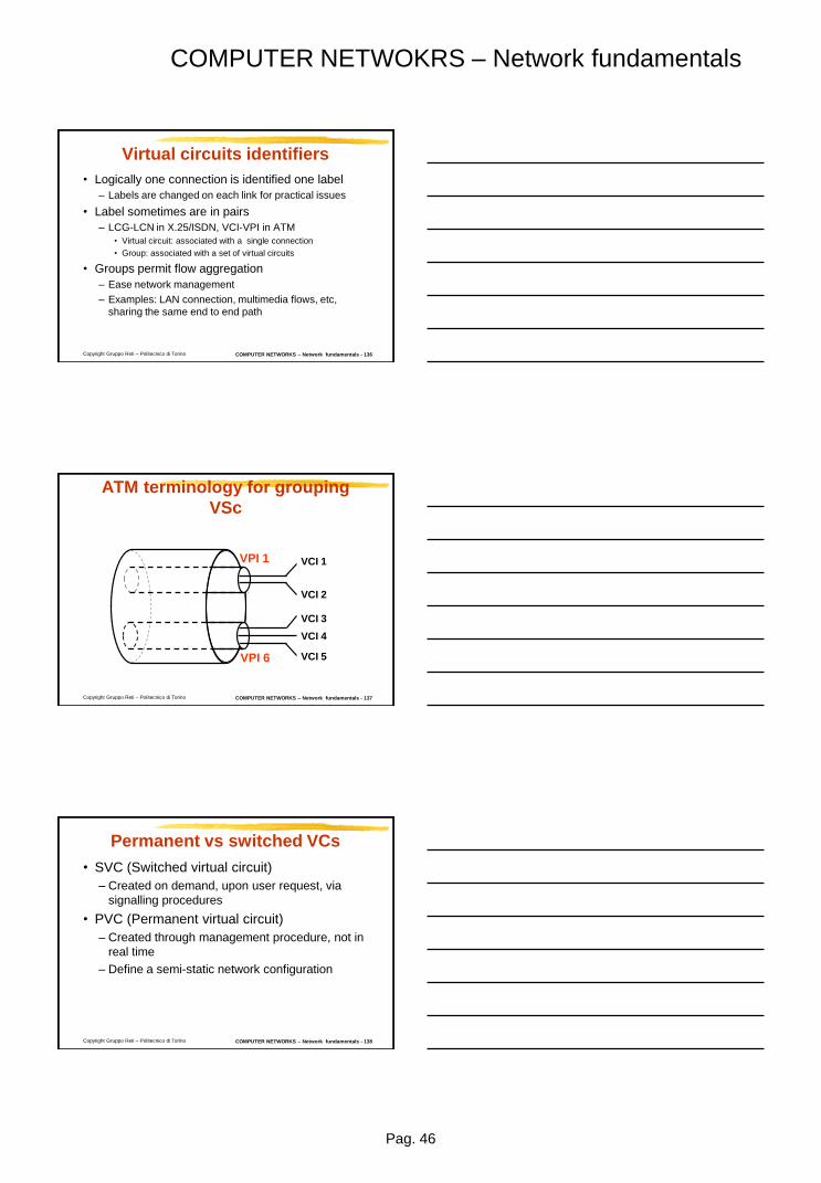
Virtual circuits identifiers
• Logically one connection is identified one label
– Labels are changed on each link for practical issues
• Label sometimes are in pairs
– LCG-LCN in X.25/ISDN, VCI-VPI in ATM
• Virtual circuit: associated with a single connection
• Group: associated with a set of virtual circuits
• Groups permit flow aggregation
– Ease network management
– Examples: LAN connection, multimedia flows, etc,
sharing the same end to end path
Copyright Gruppo Reti – Politecnico di Torino
COMPUTER NETWORKS – Network fundamentals - 137 Copyright Gruppo Reti – Politecnico di Torino
VPI 1
VPI 6
VCI 1
VCI 2
VCI 3
VCI 4
VCI 5
ATM terminology for grouping
VSc
COMPUTER NETWORKS – Network fundamentals - 138
Permanent vs switched VCs
• SVC (Switched virtual circuit)
– Created on demand, upon user request, via
signalling procedures
• PVC (Permanent virtual circuit)
– Created through management procedure, not in
real time
– Define a semi-static network configuration
Copyright Gruppo Reti – Politecnico di Torino

Pag. 47
COMPUTER NETWOKRS – Network fundamentals
COMPUTER NETWORKS – Network fundamentals - 139 Copyright Gruppo Reti – Politecnico di Torino
Signalling techniques
Gruppo Reti TLC
http://www.telematica.polito.it/
COMPUTER NETWORKS – Network fundamentals - 140
ITU-T
• Signalling: exchange of control information
associated with the setup and release of a
telephone call on a telecommunications
circuit.
Copyright Gruppo Reti – Politecnico di Torino
COMPUTER NETWORKS – Network fundamentals - 141
Signalling techniques
• Classification:
– User signalling: exchange of control information
between the user and network access node
– Network signalling: exchange of control
information among network nodes
• Type of signalling
– Associated to the channel:
• In band
• Out of band
– Common channel
Copyright Gruppo Reti – Politecnico di Torino

Pag. 48
COMPUTER NETWOKRS – Network fundamentals
COMPUTER NETWORKS – Network fundamentals - 142
Associated signalling
• There is a one-to-one correspondance
between:
– Controlling channel (signalling info)
– Contolled channel (user info)
• Used in the early days of telephone netwoks
Copyright Gruppo Reti – Politecnico di Torino
1
2
k
userdata
1
2
k
signalling
association
COMPUTER NETWORKS – Network fundamentals - 143
Signalling associated with the
channel • In band
– Controlling and controlled channels are the
same
– Used in different times
Copyright Gruppo Reti – Politecnico di Torino
1
2 k
signalling
COMPUTER NETWORKS – Network fundamentals - 144
Signalling associated with the
channel • Out of band.
– Separate controlling and controlled channels
Copyright Gruppo Reti – Politecnico di Torino
1
2 k
1
2 k
User data
signalling

Pag. 49
COMPUTER NETWOKRS – Network fundamentals
COMPUTER NETWORKS – Network fundamentals - 145
Common channel signalling
• A single signalling channel control many user
information channels
• Singalling channel is packet switched
• ITU-T SS (Signalling System) n.7
Copyright Gruppo Reti – Politecnico di Torino
1
2
k
user data
signalling
1 k
COMPUTER NETWORKS – Network fundamentals - 146 Copyright Gruppo Reti – Politecnico di Torino
Common channel signalling
• Leads to the definiton of a signalling network
– Logically (and sometimes physically) separated from
the circuit switching data networksegnalazione
• Among signalling information
– Addresses
– Addressing scheme
COMPUTER NETWORKS – Network fundamentals - 147 Copyright Gruppo Reti – Politecnico di Torino
Management techniques
Gruppo Reti TLC
http://www.telematica.polito.it/

Pag. 50
COMPUTER NETWOKRS – Network fundamentals
COMPUTER NETWORKS – Network fundamentals - 148
Network management
• Network Management organized according
to several functions:
– Configuration Management
– Performance Management
– Fault Management
– Security Management
– Accounting Management
Copyright Gruppo Reti – Politecnico di Torino
COMPUTER NETWORKS – Network fundamentals - 149 Copyright Gruppo Reti – Politecnico di Torino
Quality of service
and traffic characterization
Gruppo Reti TLC
http://www.telematica.polito.it/
COMPUTER NETWORKS – Network fundamentals - 150
Quality of service (QoS)
• In network design, traffic characteristics must
be known to provide a given service
• The amount of available resources and the
adopted switching technique (which establish
resource allocation) define QoS provided to
the users
• Network analysis and design exploit
mathematical models that permit the QoS
estimation given the available resources and
traffic behaviour Copyright Gruppo Reti – Politecnico di Torino
Pag. 51
COMPUTER NETWOKRS – Network fundamentals
COMPUTER NETWORKS – Network fundamentals - 151
Quality of service
• Network analysis
– Given
• Service requests
• Available resources
– Define
• Quality of service
• Network design
– Given
• Service requests
• Quality of service
– Define
• Needed network resources
Copyright Gruppo Reti – Politecnico di Torino
COMPUTER NETWORKS – Network fundamentals - 152
Quality of service
• Need to rely on mathematical models to:
– Characterize service requests
– Describe interaction among activities and
resources
– Compute quality of service
Copyright Gruppo Reti – Politecnico di Torino
COMPUTER NETWORKS – Network fundamentals - 153
Traffic characterization
• Analog sources: voice, video
– Defined through their spectral characterization
(required bandwidth, correlation, ...)
• Digital (or digitalized) sources: data, voice,
video
– Defined through average bit rate and burstiness
Copyright Gruppo Reti – Politecnico di Torino

Pag. 52
COMPUTER NETWOKRS – Network fundamentals
COMPUTER NETWORKS – Network fundamentals - 154
Traffic characterization
• Digital sources
– Constant Bit Rate - CBR
• Voice (64 kb/s)
• Videoconference (n x 64 kb/s)
• Uncompressed video (180Mb/s)
– Variable Bit Rate - VBR
• Compressed voice (tens of kb/s)
• MPEG video (Mb/s)
• file transfer (from kb/s to Mb/s to Gb/s)
Copyright Gruppo Reti – Politecnico di Torino
COMPUTER NETWORKS – Network fundamentals - 155
Traffic characterization
• CBR sources
– Bit rate (bit/s)
• Packet size
– Call duration (s)
– Call generation process
Copyright Gruppo Reti – Politecnico di Torino
COMPUTER NETWORKS – Network fundamentals - 156
Traffic characterization
• VBR sources
– Peak rate (bit/s)
– Average rate (bit/s)
• Over which time window?
– Burstiness is defined as peak rate/average rate
– Call duration (s)
– Call generation process
Copyright Gruppo Reti – Politecnico di Torino

Pag. 53
COMPUTER NETWOKRS – Network fundamentals
COMPUTER NETWORKS – Network fundamentals - 157
Traffic characterization
• How to control traffic shape
Copyright Gruppo Reti – Politecnico di Torino
L
V1
V2
source network
token
bucket
COMPUTER NETWORKS – Network fundamentals - 158
QoS parameters
• Different applications have different
requirements
• QoS indices:
– Delay (average, percentile, wors case)
– Bit rate
– Error probability
– Loss probability
– Call blocking probability
Copyright Gruppo Reti – Politecnico di Torino
COMPUTER NETWORKS – Network fundamentals - 159
QoS indices: example
• Phone calls
– CBR source
– Worst case delay of hundredths of milliseconds
• Real time communication
– Bit rate of 64 kbit/s
– Error probability of few %
– Negligible call blocking probability
Copyright Gruppo Reti – Politecnico di Torino

Pag. 54
COMPUTER NETWOKRS – Network fundamentals
COMPUTER NETWORKS – Network fundamentals - 160
QoS indices: example
– VBR source
– No requirements on delay (minutes is fine)
– No requirements on bit rate
– Negligible error probability
– Negligible blocking probability
Copyright Gruppo Reti – Politecnico di Torino
COMPUTER NETWORKS – Network fundamentals - 161
QoS indices: example
• Video on demand
– VBR source
– Maximun delay of few seconds
– Bit rate of Mbit/s
– Small error probability
– Negligible call blocking probability
Copyright Gruppo Reti – Politecnico di Torino
COMPUTER NETWORKS – Network fundamentals - 162
105
104
103
102
101
1 hour
1 min
telemetry
101 102 103 104 105 106 107 108
hi-fi audio video
videoconference low speed data
fax
voice video
telephony
Co
nn
ecti
on
du
rati
on
[s]
1
Speed
[bit/s] 1 kbit/s 1 Mbit/s
high
speed
data
Service characteristics

Pag. 55
COMPUTER NETWOKRS – Network fundamentals
COMPUTER NETWORKS – Network fundamentals - 163
low
speed
data
alphanumeric
terminals
LAN alta velocità
immagini
connectionless
data
transmission
supercomputer
interconnection
voice audio
HDTV VIDEO
compressed
non compressed
Bu
rsti
ne
ss
Peak rate [bit/s]
103 104 105 106 107 108 109 1010
1000
100
10
1
LAN
graphical
terminal
Burstiness= Peak rate/ Average rate
Traffic characterization