Computer communications (ELEC2402) Year 2
356
Computer communications (ELEC2402) Year 2 Dr. W. H. LAM Text Books: (1) “Computer Networks” - Fourth Edition by Andrew S. Tanenbaum, Prentice Hall (2) “Data and computer communications” – Seventh edition by William Stallings, Prentice Hall ELEC2402 Pg 2 CONTENTS A. Introduction to Data Network 4 1. The uses of computer and data networks 5 2. Network topology 6 3. Network Architectures 9 4. The OSI Reference Model 11 5. Services 20 6. Network Standardization 25 7. The Internet 27 8. Summary 30 B. The Physical Layer (Layer 1) 31 1. Theoretical Basis for Data Communication 32 2. Transmission media 36 3. Data Encoding for transmission 43 4. Asynchronous and Synchronous Transmission 47 5. RS232-C 51 6. RS-499 57 7. Analog Transmission 59 8. Trunks and Multiplexing 70 9. Circuit switching 72 10. Packet Switching 74 C. The Data Link Layer (Layer 2) 76 1. Data link layer design issues 77 2. Error detection and correction 90 3. Elementary Data link protocols 106 4. Sliding Window Protocols 117 5. Protocol performance 143 6. Example Data link protocols 154 D. The Medium Access Control Sub Layer 170 1. The Channel Allocation Problem 172 2. Multiple access protocols 173 3. Ethernet 186
Transcript of Computer communications (ELEC2402) Year 2

Computer communications
(ELEC2402)Year 2
Dr. W. H. LAM
Text Books:(1) “Computer Networks” - Fourth Edition
by Andrew S. Tanenbaum, Prentice Hall
(2) “Data and computer communications” – Seventh editionby William Stallings, Prentice Hall
ELEC2402 Pg 2
CONTENTS
A. Introduction to Data Network 41. The uses of computer and data networks 52. Network topology 63. Network Architectures 94. The OSI Reference Model 115. Services 206. Network Standardization 257. The Internet 278. Summary 30
B. The Physical Layer (Layer 1) 311. Theoretical Basis for Data Communication 322. Transmission media 363. Data Encoding for transmission 434. Asynchronous and Synchronous Transmission 475. RS232-C 516. RS-499 577. Analog Transmission 598. Trunks and Multiplexing 709. Circuit switching 7210. Packet Switching 74
C. The Data Link Layer (Layer 2) 761. Data link layer design issues 772. Error detection and correction 903. Elementary Data link protocols 1064. Sliding Window Protocols 1175. Protocol performance 1436. Example Data link protocols 154
D. The Medium Access Control Sub Layer 1701. The Channel Allocation Problem 1722. Multiple access protocols 1733. Ethernet 186

ELEC2402 Pg 3
E. The Network Layer (Layer 3) 1901. Network layer design issues 1912. Routing Algorithms 1953. Congestion control algorithms 2044. Quality of service 2075. Internetworking 221
F. Introduction to TCP (Layer 4)/ IP(Layer 3) 2271. Basic operations of TCP/IP: 2312. Resolution of IP address 2403. IP Datagram 2454. Routing of IP Datagrams/Fragments 2505. Internet Control Message Protocol (ICMP) 2576. Internet Multicasting 2607. Transport Protocol: TCP 2678. UDP Connectionless Services 285
G. The Application Layer (Layer 7) 2891. The Domain Name System 2902. Electronic Mail 2953. Multimedia 298
H. Network Security 3001. Aspects of network security 3012. Encryption 3023. Digital signature 3064. Authentication protocols 3085. E-Mail Security 3116. Web Security 3127. Packet filtering and firewall 316
I. Example Networks 3181. ISDN (Integrated Services Digital Network) 3192. Asynchronous Transfer Mode (ATM) 348
ELEC2402 Pg 4
Section A
Introduction to Data Network
1. The uses of computer and data networks
2. Network topology
3. Network Architectures
4. The OSI Reference Model
5. Services
6. Network Standardization
7. The Internet
8. Summary

ELEC2402 Pg 5
1. The uses of computer and data networks
Purposes:• Sharing information (or data);• Sharing hardware and software;• Centralizing administration and support;• Higher reliability and saving money.
Classification of interconnected processors by scale:
Inter-processordistance
Processors locatedin same
Example
1m Square meter Personal area network
10m Room100m Building1km Campus
Local area network (LAN)
10km City Metropolitan area network(MAN)
100km Country1000km Continent
Wide area network (WAN)
10,000km Planet The Internet
Figure A-1 Classification of interconnected processors by scale
ELEC2402 Pg 6
2. Network topology
Arrangement or physical layout of computers, cables, and othercomponents on the network.
The network consists of transmission lines (e.g., circuit, channel,trunks) and switching elements (e.g., IMP, packet switch mode..)
Figure A-2 Relation between hosts and the subnet. (The originalARPANET design.)
2 types of designs for communication subnet:
(a) Point-to-point channel
(b) Broadcast channels
which carry messagefrom host to host; justlike the telephonesystems carries wordsform speakers tospeakers.
IMP = Interface Message Processor
ELEC2402 Pg 7
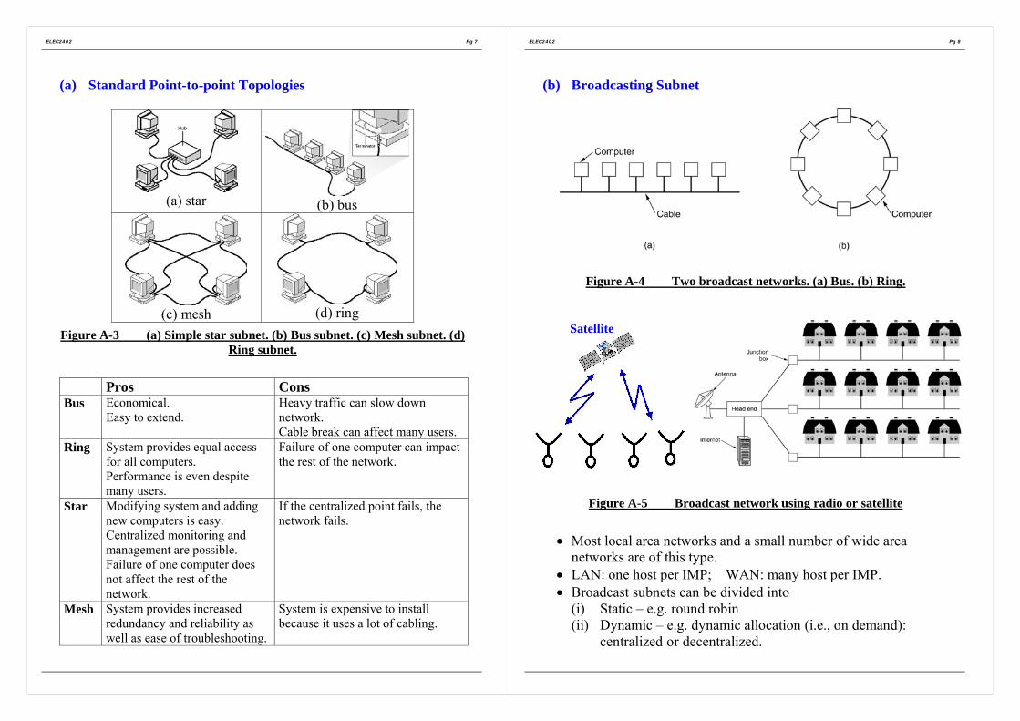
(a) Standard Point-to-point Topologies
(a) star (b) bus
(c) mesh (d) ringFigure A-3 (a) Simple star subnet. (b) Bus subnet. (c) Mesh subnet. (d)
Ring subnet.
Pros ConsBus Economical.
Easy to extend.Heavy traffic can slow downnetwork.Cable break can affect many users.
Ring System provides equal accessfor all computers.Performance is even despitemany users.
Failure of one computer can impactthe rest of the network.
Star Modifying system and addingnew computers is easy.Centralized monitoring andmanagement are possible.Failure of one computer doesnot affect the rest of thenetwork.
If the centralized point fails, thenetwork fails.
Mesh System provides increasedredundancy and reliability aswell as ease of troubleshooting.
System is expensive to installbecause it uses a lot of cabling.
ELEC2402 Pg 8
(b) Broadcasting Subnet
Figure A-4 Two broadcast networks. (a) Bus. (b) Ring.
Figure A-5 Broadcast network using radio or satellite
• Most local area networks and a small number of wide areanetworks are of this type.
• LAN: one host per IMP; WAN: many host per IMP.• Broadcast subnets can be divided into
(i) Static – e.g. round robin(ii) Dynamic – e.g. dynamic allocation (i.e., on demand):
centralized or decentralized.
Satellite

ELEC2402 Pg 9
3. Network Architectures
- To reduce the design complexity, most networks are organized asa stack of layers or levels, each one built upon its predecessor.
Figure A-6 Layers, protocols, and interfaces.
ELEC2402 Pg 10
Figure A-7 Example information flow supporting virtualcommunication in layer 5
M=Message H=Header T=Trailer

ELEC2402 Pg 11
4. The OSI Reference Model
ISO OSI => developed by International Standard Organization (ISO)andOSI = Open Systems Interconnection
Figure A-8 The network architecture used in this notes. It is based onthe OSI model.
ELEC2402 Pg 12
The ISO (International Standard Organization)OSI (Open Systems Interconnection) Reference model has sevenlayers
The principles that were applied to arrive at the seven layers are asfollows:
(a) A layer should be created where a different level ofabstraction is needed.
(b) Each layer should perform a well-defined function.
(c) The function of each layer should be chosen with an eyetoward defining internationally standardized protocols.
(d) The layer boundaries should be chosen to minimize theinformation flow across the interfaces.
(e) The number of layers should be large enough that distinctfunctions need not be thrown together in the same layer outof necessity, and small enough that the architecture does notbecome unwieldy.

ELEC2402 Pg 13
(1) The Physical layer• It is concerned with transmitting raw bits over a
communication channel, making sure that when one side sendsa 1 bit, it is received by the other side as a 1 bit, not as a 0 bit.
• Issues such as? volts represents 1 ;? volts represents 0 ;transmission bit rate ;simultaneously transmission in both directions ;how the initial connection is established, andhow it is turn down when both sides are finished ;how many pins and pin connections ?
(2) The Data Link Layer
• It takes a raw transmission facility and transforms it into a linethat appears free of transmission errors to the network layer. Itaccomplishes this task by having the sender break the input dataup into data frames (typically a few hundred bytes), transmit theframes sequentially and process the acknowledgement framessent back by the receiver.
• Because the physical layer merely accepts and transmits a streamof bits without any regard to meaning or structure, it is up to thedata link layer to create and recognize frame boundaries usingheader/trailer.
• The data link later need to solve the problem caused by damages,lost and duplicated frame.
• The data link layer may offer several different services classes tothe Network Layer.
ELEC2402 Pg 14
(3) The Network Layer
• It is concerned with controlling the operation of the subnet.
• A key design issue is determining how packets are routed fromsource to destination.
• Routes could be based on:o Static tables ;o or determined at the start of each conversation;
for example, a terminal session.o or be highly dynamic, being determined anew for each
packet, to reflect the current network load
• The control of congestion also belongs to the network layer.
• The network layer is also concerned with:o Accounting function ;o Billing.
• It is also up to the network layer to overcome all the problems toallow heterogeneous networks (different networks) to beinterconnected.
• In broadcast networks, the routing problem is simple, so thenetwork layer is often thin or even non-existent.

ELEC2402 Pg 15
(4) The Transport Layer
• The basic function is to accept data from the Session Layer, splitit up into smaller units if need be, pass these to network layer,and ensure that the pieces all arrive correctly at the other end.Furthermore, all this must be done efficiently, and in a way thatisolates the session layer from the inevitable changes in thehardware technology.
• The transport layer might multiplex several transportconnections onto the same network connection to reduce thecost. The transport layer is required to make the multiplexingtransparent to the session layer.
• The transport layer also determines what type of service toprovide the session layer, and ultimately, the users of the network.
The most popular type of transport connection is an error-freepoint-to-point channel that delivers messages in the order whichthey were sent. However, other possible kinds of transportservice are transport of isolated messages with no guaranteedabout the order of delivery, and broadcasting of messages tomultiple destinations.
• The transport layer is a true source-to-destination or end-to-endlayer.
Layers 1 through 3 are chained whilelayers 4 through 7 are end-to-end, is illustrated in Figure A-8.
ELEC2402 Pg 16
(5) The Session layer
• The session layer allows users on different machines to establishsessions between them.
A session allows ordinary data transport, as does the transportlayer, but it also provides some enhanced services useful in someapplications.
A session might be used to allow a user to log into a remote time-sharing system or to transfer a file between two machines.
• Token management:For some protocols, it is essential that both sides do not attemptthe same operation at the same time. To manage these activities,the session layer provides tokens that can be exchanged. Only theside holding the token may perform the critical operation.
• Synchronization:Consider the problems that might occur when trying to do a two-hour file transfer between two machines on a network with one-hour mean time between crashes.To eliminate this problem, the session layer provides a way toinsert checkpoints into the data stream, so that after a crash, onlythe data after the last checkpoint have to be repeated.

ELEC2402 Pg 17
(6) The Presentation Layer
• The presentation layer is concerned with the syntax andsemantics of the information transmitted.
A typical example of a presentation service is encoding data in astandard agreed upon way.
In order to make it possible for computers with differentrepresentations to communicate, the data structures to beexchanged can be defined in an abstract way, along with astandard encoding to be used “on the wire”. The job of managingthese abstract data structure and converting from therepresentation used inside the computer to the network standardrepresentation is handled by the presentation layer.
The presentation layer is also concerned with other aspects ofinformation representation.For example, data compression can be used here to reduce thenumber of bits that have to be transmitted.
ELEC2402 Pg 18
(7) The Application Layer
• The application layer contains a variety of protocols that arecommonly needed.e.g., there are hundreds of incompatible terminal types in the
world.
One way to solve this problem is to define an abstract networkvirtual terminal that editors and other programs can be written todeal with.
To handle each terminal type, a piece of software must be writtento map the functions of the network virtual terminal onto the realterminal.All the virtual terminal software is in the application layer.
• Another application layer function is file transfer. Different filesystems have different file naming conventions, different ways ofrepresenting that lines, and so on.
Transferring a file between two different systems requireshandling these and other incompatibilities. This work, too,belongs to the application layer, as do electronic mail, remote jobentry, directory lookup, and various other general purpose andspecial purpose facilities.

ELEC2402 Pg 19
Example:
SendingProcess↓
← Data → ReceivingProcess↑
Applicationlayer
Application protocol ← AH Data → Applicationlayer
Presentationlayer
Presentation protocol ← PH Data → Presentationlayer
Sessionlayer
Session protocol ← SH Data → Sessionlayer
Transportlayer
Transportprotocol ←
TH Data → Transportlayer
Networklayer
Networkprotocol
←
NH Data → Networklayer
Data linklayer
← DH Data DT → Data linklayer
Physicallayer
← Bits(Actual data transmission path)
→ Physicallayer
Figure A-9 An example of how OSI model is used. Some of theheaders may be null.
ELEC2402 Pg 20
5. Services
Figure A-10 The relationship between a service and a protocol.
• A service is a set of primitives (operations) that a layer providesto the layer above it. The service defines what operations thelayer is prepared to perform on behalf of its users without sayinghow these operations are implemented.
• A protocol, in contrast, is a set of rules governing the format andmeaning of the packets.

ELEC2402 Pg 21
Connection-Oriented and Connectionless Services
Service ExampleReliable message stream Sequence of pages
Reliable byte stream Remote login
Connectionoriented
Unreliable connection Digitized voice
Unreliable datagram Electronic junk mail
Acknowledged datagram Registered mail
Connectionless
Request-reply Database query
Figure A-11 Six different types of service.
Connection-oriented Service is modeled after the telephone system.That is, the service user first establishes a connection, use theconnection, and then terminates the connection. – circuit-switched.
Connectionless Service is modeled after the postal system. Each(letter) carries the full destination address, and each one is routedthrough the system independent of all the others. – packet-switched.
ELEC2402 Pg 22
Service Primitives
• A service is formally specified by a set of primitives (operations)available to a user process to access the service.
• These primitives tell the service to perform some action or reporton an action taken by a peer entity.
• The set of primitives available depends on the nature of theservice being provided. The primitives available for connection-oriented service are different from those of connectionlessservice.
(i) Connection-oriented servicesAs a minimal example of the service primitives that might beprovided to implement a reliable byte stream in a client-serverenvironment, consider the primitives listed in Figure A-12.
Primitive MeaningLISTEN Block waiting for an incoming connection
CONNECT Establish a connection with a waiting peer
RECEIVE Block waiting for an incoming message
SEND Send a message to the peer
DISCONNECT Terminate a connection
Figure A-12 Five service primitives for implementing a simpleconnection-oriented service.

ELEC2402 Pg 23
For example (a connection-oriented network):
Figure A-13 Packets sent in a simple client-server interaction on aconnection-oriented network.
1. Connect request Request a connection to be established by sending apacket to the peer.
2. Connect ACK Checks to see if there is a listener, if so unblocks thelistener and sends back an acknowledgment.(Note that the acknowledgement is generated by theprotocol code)
3. Request for data Request that data be sent.
4. Reply Signal arrival of data.
5. DisconnectRequest
Request that a connection be released.
6. Disconnect ACK Signal the client machine, the client process isreleased and the connection is broken.
ELEC2402 Pg 24
(ii) Connectionless services
For connectionless network protocol such as UDP, two serviceprimitives are used as described below:
Primitive MeaningRECEIVE Block waiting for an incoming message
SEND Send a message to the peer
Figure A-14 Two service primitives for implementing a simpleconnectionless service.

ELEC2402 Pg 25
6. Network Standardization
Who’s who in the telecommunication world:• PTT (Post, Telegraph & Telephone)• ITU (International Telecommunication Union, known as CCITT
before March 1, 1993)• AT&T (American Telegraph & Telephone)
Who’s who in the International Standards world:• ISO (International Standards Organization)
89 member countries including ANSI (U.S.), BSI (Great Britain),AFNOR (France), DIN (Germany) and etc.ISO is a voluntary, nontreaty organization founded in 1946.
• IEEE (Institute of Electrical & Electronic Engineers)• EIA (Electronic Industries Alliance, formerly known as
Electronic Industries Association).
Who’s who in the Internet Standards world:• IAB (Internet Activities Board)• RFCs (Request For Comments, http://www.ietf.org/rfc)• IRTF (Internet Research Task Force)• IETF (Internet Engineering Task Force)
The procedure used by ISO for adopting standards:• A working group is formed to come up with a DP (Draft Proposal)• The DP is then circulated to all the member bodies, which get 6
months to criticize it.• If a substantial majority approves, a revised document, called a
DIS (Draft International Standard) is produced and circulated forcomments and voting.
• Based on the results of this round, the final text of the IS(International Standard) is prepared, approved, and published.
ELEC2402 Pg 26
Figure A-15 The apocalypse of the two elephants.
This figure shows the amount of activity surrounding a new subject.

ELEC2402 Pg 27
7. The Internet
Internet is:• A network of networks, joining many government, university
and private computers together and providing an infrastructurefor the use of E-mail, bulletin boards, file archives, hypertextdocuments, databases and other computational resources;
• The vast collection of computer networks which form andact as a single huge network for transport of data and messagesacross distances which can be anywhere from the same officeto anywhere in the world;
• The largest network of networks in the world;• Uses TCP/IP protocols and packet switching;• Runs on any communications substrate;• Provide certain common services.
A brief history of Internet:
Since Dec. 1969, it has been operating and has been operatingand has subsequently grown to several hundred computersspanning half the globe from Hawaii to Sweden. Much of ourpresent knowledge about networking is a direct result of theARPANET (Advanced Research Project Agency NETwork ofthe U.S. Department of Defense, created in the late 1960s.)project. (ARPA - Advanced Research Project Agency now known asDARPA – Defense Advanced Research Project Agencyhttp://www.darpa.mil)
Then, a military network, MILNET, was set up usingARPANET technology. An extension of MILNET in Europe,called MINET, was also created.
ELEC2402 Pg 28
MILNET and MINET are connected to ARPANET. Two satellitenetworks, SATNET and WIDEBAND were also hooked up later.
Since many of the universities and government contractors on theARPANET had their own LANs, eventually these were alsoconnected to the IMPs, leading to the ARPA Internet withthousands of hosts and well over 100,000 users.
The ARPANET IMPs are also called PSNs (Packet SwitchNodes). Some of the IMPs have been configured to allow userterminals to call them directly, instead of logging into a host.These are called TACs (Terminal Access Controllers).
The ARPANET does not follow the OSI model at all. (Itpredates OSI by more than a decade.)
One of the more interesting challenges was the transition of theARPANET host protocol from NCP (Network Control Protocol)to TCP/IP as of January 1, 1983. This was a "flag-day" styletransition, requiring all hosts to convert simultaneously or be lefthaving to communicate via rather ad-hoc mechanisms. Thistransition was carefully planned within the community overseveral years before it actually took place and went surprisinglysmoothly.
TCP/IP was adopted as a defense standard three years earlierin 1980. This enabled defense to begin sharing in the DARPAInternet technology base and led directly to the eventualpartitioning of the military and non- military communities. By1983, ARPANET was being used by a significant number ofdefense R&D and operational organizations. The transition ofARPANET from NCP to TCP/IP permitted it to be split into aMILNET supporting operational requirements and an ARPANETsupporting research needs.

ELEC2402 Pg 29
Thus, by 1985, Internet was already well established as atechnology supporting a broad community of researchers anddevelopers, and was beginning to be used by other communitiesfor daily computer communications. Electronic mail was beingused broadly across several communities, often with differentsystems, but interconnection between different mail systems wasdemonstrating the utility of broad based electroniccommunications between people.
Figure A-16 Internet history
ELEC2402 Pg 30
8. Summary
• Networks are being developed both to connect existing machinesand to take advantage of the low-cost, high-performancemicroprocessors the semiconductor industry to turning out.
• Most side area networks have a collection of hostscommunication via a subnet.
• The subnet may utilize multiple point-point lines between itsIMF, or a single common broadcast channel, as in a satellitenetwork
• Local-area networks connect the hosts directly onto a cable usingan interface chip that is somewhat analogous to the IMP in awide area network.
• Networks are always designed a series of protocol layers, witheach layer responsible for some aspect of the network’s operation.=> The seven-layer OSI model.
• The physical layer (1) is concerned with standardizing networkconnectors and their electrical properties.
• The data link layer (2) breaks the raw bit stream up into discreteunits and exchanges these units using a protocol
• The network layer (3) takes care of routing.• The transport layer (4) provides reliable, end-to-end connections
to the higher layers.• The session layer (5) enhances the transport layer by adding
facilities to help recover from crashes and other problems.• The presentation layer (6) deals with standardizing the way data
structures are described and represented.• The application layer (7) contains file transfer, electron mail,
virtual terminal, and a number of application specific protocols.

ELEC2402 Pg 31
Section B
The Physical Layer (Layer 1)
1. Theoretical Basis for Data Communication
2. Transmission media
3. Data Encoding for transmission
4. Asynchronous and Synchronous Transmission
5. RS232-C
6. RS-499
7. Analog Transmission
8. Trunks and Multiplexing
9. Circuit switching
10. Packet Switching
ELEC2402 Pg 32
1. Theoretical Basis for Data Communication
1.1 Fourier SeriesAny behaved periodic function, g(t), with period T can be constructed/ represented by summing a (possibly infinite) number of sines andcosines:
1 1
1( ) sin(2 ) cos(2 )2 n n
n n
g t c a nft b nftπ∞ ∞
= =
= + +∑ ∑where
1fT
= = the fundamental frequency, and na and nb are the sineand cosine amplitudes of the n-th harmonics (terms).
Such decomposition is called a Fourier Series.
The values of c, na and nb are given by:
0
0
0
2 ( )
2 ( ) sin(2 )
2 ( ) cos(2 )
T
T
n
T
n
c g t dtT
a g t nft dtT
b g t nft dtT
π
π
= ⋅
= ⋅ ⋅
= ⋅ ⋅
∫
∫
∫Note that a data signal that has a finite duration (which all of them do)can be handles by just imagining that it repeats the entire pattern overand over forever (i.e., the interval from T to 2T in the same as from 0to T, etc).

ELEC2402 Pg 33
1.2 Bandwidth-Limited SignalsConsider an example of the transmission of the ASCII character “b”encoded in an 8-bit byte.The bit pattern to be transmitted is 0100 0010 as shown in Figure B-1.The Fourier analysis of this signal yields the coefficients:
1 3 6 7[cos( ) cos( ) cos( ) cos( )]4 4 4 4
1 3 7 6[sin( ) sin( ) sin( ) sin( )]4 4 4 4
38
n
n
n n n nan
n n n nbn
c
π π π ππ
π π π ππ
= − + −
= − + −
=
The root-mean-square amplitudes,2 2
n na b+ , for the first few termsare show on the right-hand side of Figure B-1(a).These values are of interest because their squares are proportional tothe energy transmitted at the corresponding frequency.
Complex exponential Fourier Series:2 2
n n nC a b= +
/ 2
/ 2
/ 2
/ 2
1
1( ) ; ; (2 )
1 ( ) ;
1 ( )
tan
n
n
n
n
j tn n o o
n
Tj t
nT
Tj t
nT
j nn
n
f t C e nT
where
C f t e dt T periodT
C f t e dtT
bCn Cn e wherea
ω
ω
ω
θ
ω ω ω π
θ
∞−
=−∞
−
−
−−
−
= = =
= =
=
= =
∑
∫
∫
ELEC2402 Pg 34
Figure B-1 (a) binary signal and its rms Fourier amplitudes, (b)-(e)Successive approximations to the original signal.
Fourier Series
Increasing bandwidth& improving the shapeof waveform.

ELEC2402 Pg 35
1.3 The Maximum Data Rate of a Channel
If a signal is bandwidth limited by a low pass filter having bandwidthof H Hz and it consists of V discrete levels, Nyquist’s theorem states:(noiseless channel)
Maximum data rate = 22 log bits/secH V
E.g., A noiseless 3kHz channel cannot Tx binary (i.e., two level)signal at a rate exceeding 6k bit/sec.
However, for noisy channel:Shannon: The maximum data rate of a noisy channel whose
bandwidth is H Hz, and whose signal-to-noise ratio is S/N,is given by:
Maximum number of bits/sec = 2log (1 / )H S N+
E.g., For example: a channel of 3kHz bandwidth, and a signal-to-thermal noise ratio of 30dB (typical parameters of the telephonesystem) can never transmit over more than
23kHz log (1 1000) 30k b/s⋅ + ≈ ,
no matter how many or few signal levels are used and no matterhow often or how infrequent samples are taken.Note that this only an upper bound. In practice, it is difficult toeven approach the Shannon limit.
ELEC2402 Pg 36
2. Transmission media
• Various physical media can be used for transmission.
2.1 Magnetic media=> Magnetic tape or floppy disks
• Physically transport the tape or dist in which data were written byone computer, to the destination machine/computer, and readthem back in again.
• This method can be very cost effective, especially forapplications in which cost/bit transported is the key factor.
• An industry standard Ultrium tape can hold 2000 gigabytes..
2.2 Twisted Pair
• For many applications, an on-line connection is needed, astransmission time is critical, e.g. telephone line.
• A twisted pair consists of two insulated copper wires, about 1mmthick typically. The twisted form reduces electrical interferenceto similar pairs close by. (Two parallel wires constitute as simpleantenna; a twisted pair does not).
• Nearly all telephones are connected to the telephone companyoffice by a twisted pair. Twisted pairs can run several km withoutamplification, but for longer distances, repeaters are needed.
• Twisted pairs can be used for either analog or digitaltransmission. The bandwidth depends on the thickness of thewire and the distance traveled, but several M bit/sec can beachieved for a few km in many cases.
• Due to heir adequate performance and low cost, twisted pairs arewidely used and are likely to remain so for years to come.

ELEC2402 Pg 37
2.3 Coaxial Cable
Two kind of coaxial cable are widely used:(a) 50-ohm cable (used for digital transmission) ;(b) 75-ohm cable (is used for analog transmission).
Figure B-2 A coaxial cable
(a) Baseband: 50-ohm cable (digital transmission)• The construction of the coaxial cable fives it a good combination
of high bandwidth and excellent noise immunity.• The bandwidth possible depends on the cable length. For 1 km
cable, a data rate of 10M b/s is feasible. Higher data rates arepossible on shorter cables.
• Coaxial cables are widely used for local area network and forlong-distance transmission with the telephone system.
(b) Broadband coaxial cable: 75-ohm cable (analog transmission)• It is used for analog transmission on standard cable television.• Modern cables have a bandwidth of close to 1GHz• Broadband systems are normally divided up into multiple
channels frequency the 6MHz channels used for televisionbroadcasting. Each channel can be used for analog television,high-quality audio, or a digital bit stream at, say, 3Mb/s,independent of the other channels. Television and data can bemixed on the same cable.
ELEC2402 Pg 38
2.4 Fiber Optics
• An optical transmission system has three components:(a) the transmission media, (b) the light source (c) the detector
• The transmission medium is an ultra-thin fiber of glass or fused silica.• The light source is either LED (Light Emitting Diode), or a laser diode,
both of which emit light pulses when an electrical current is applied.• The detector is a photodiode, which generates an electrical pulse when
light fall on it.• A light pulse can be used to signal a 1 bit; the absence of a pulse signals a
0 bit.• Fiber optic links are being installed for long-distance telephone lines in
many countries. This trend will continue during the next few decades,with coaxial cable being replaced by firer on more and more routes.
Figure B-3 (a) Three examples of a light ray from inside a silica fiberimpinging on the air/silica boundary at different angles. (b) Light trapped
by total internal reflectionAs shown in Figure B-3, for angles of incidence above a certain critical value,the light is refracted back into the silica; none of it escapes into the air (orreflection). => critical angle.
• However, if the fiber’s diameter is reduced to one wavelength of light,the firer acts like a wave guide, and the light will propagate in a straightline, without bouncing, yielding a single mode fiber.
• Single mode fiber require (expensive) laser diodes to drive them, ratherthan (inexpensive) LEDs, but they are more efficient and can be run forlonger distances.
• Currently available firer optics system can transmit data at 50Gbps for100km without amplification.

ELEC2402 Pg 39
Fiber Optic Networks
• Fibers can also form the basis for LANs, although the technology is morecomplex; the process of making a tap is very tricky and substantial lightis lost.
• One way around the problem is to realize that a ring network is really justa collection of point-to point links, as shown in Figure B-4. The interfaceat each computer passes the light pulse stream through to the next linkand also serves as a T-junction to allow the computer to send and acceptmessages.
• Two type of interfaces are used:A passive interface consists of two taps fused onto the main fiber. Onetap has an LED or laser diode at the end of it (for transmitting) and theother end has a photodiode (for receiving). The tap itself if completelypassive and is this extremely reliable because a broken LED orphotodiode does not break the ring. It just takes one computer off-line.
Figure B-4 A fiber optic ring with active repeaters.
Active repeaterThe other interface type, shown in Figure B-4 is the active repeater.The incoming light is converted to an electrical signal, regenerated to fullstrength if it has been weaken, and retransmitted as light.
• The interface with the computer is an ordinary copper wire that comesinto the signal regenerator.
• If an active repeater fails, the ring is broken and the network goes down.• On the other hand, since the signal is regenerated at each interface, the
individual computer-to-computer links can be kilometers long, with
(tapping)
ELEC2402 Pg 40
virtually no limit on the total size of the ring. (The passive interface loselight at each junction, so the number of computers and total ring lengthare greatly restricted.)
Passive star connection:It is also possible to have hardware broadcasting using the passive starconstructed to build a LAN using fiber optics as shown in Figure B-5.
Figure B-5 A passive star connection in a fiber optics network
• Each interface has a fiber running from its transmitter to a silica cylinder,with the incoming fiber fused to one end of the cylinder. Similarly, fiberfused to the other end of the cylinder (performing XOR) are run to eachof the receivers.
• Whenever an interface emits a light pulse, it is diffused inside the passivestar to illuminate all the receivers thus achieving broadcast.
• In effect, the passive star performs a Boolean OR of all the incomingsignals and transmitting the result on all lines. Since the incoming energyis divided among all the outgoing lines, the number of nodes in thenetwork is limited by the sensitivity of photodiode.

ELEC2402 Pg 41
2.5 Line of sight transmission (Wireless)• Laser or infrared communication is fully digital, and highly
direction, making it almost immune to tapping or jamming. Onthe other hand, rain and fog may interfere with thecommunication, depending on the wavelength chosen.
• For long distance communication, microwave radio transmissionis widely used as an alternative to coaxial cable.Parabolic antennas can be mounted on towers to send a beam toanother antenna tens of kilometers away. This system is widelyused for both telephone and television transmission.The higher the tower, the greater the range.With a 100 meter high tower, distance of 100km between towersare feasible.The advantage: cheaper than digging a 100km trench, layer
cable or fiber in it.Microwave propagation is affected by thunderstorms and otheratmospheric phenomena.
• Most u-wave transmission occurs at 2GHz to 40GHzcorresponding to wavelength of 15cm to 0.75 cm. Thesefrequencies have been divided into bands of common carrier,government, military and other used.
• Most long distance telephone traffic takes place in the range 4-6GHz although it is increasingly overcrowded.Higher frequencies are available, but they are less useful forlong-distance Tx as the attenuation is greater at higher frequency.
ELEC2402 Pg 42
2.6 Communication Satellites
• A communication satellite can be thought of as a big microwaverepeater in the sky.
• It contains one or more transponders, each of which listens tosome portion of spectrum, amplifies the incoming signal, andthen rebroadcasts it at another frequency, to avoid interferencewith the incoming signal.
• The downward beams can be broad, covering substantial fractionof the earth’s surface; or narrow, covering an area hundreds ofkilometers in diameter.
• At an altitude of ~36,000km above the equator, the satelliteorbital period is 24 hours, so it revolves at the same rate as theearth under it (i.e, Geo-stationary).An observer looking at a satellite in a circular equatorial orbit seethe satellite hand in a fixed spot in the sky, apparently motionless/ stationary.Having the satellite be fixed in the sky is extremely desirable,because otherwise an expensive steerable antenna would beneeded to track it.Communication satellite at lower altitudes (less than 36,000km)are not very useful because they are within sight of the groundsfor only a short time interval.

ELEC2402 Pg 43
3. Data Encoding for transmission
Binary data must be encoded appropriate signals for transmission overthe physical medium. Different signal elements are used to representbinary 1 and binary 0.
3.1 Non-return-to-zero (NRZ)
The simplest encoding scheme is NRZ (non-return-to-zero). Twodifferent voltage levels, one positive and one negative are used assignal elements to represent the two binary digits. The voltagemaintains a constant level during a bit period. The signal voltage levelnever returns to zero. This scheme is also known as NRZ-L (level).
Two schemes of NRZ: High => 0 or Low => 0.
There is a variation of NRZ, called NRZI (non-return-to-zero-inverted). The data are encoded as the presence or absence of a signaltransition at the beginning of a bit time.
Two NRZI schemes: NRZI-0 (transition at 0 only) andNRZI-1 (transition at 1 only).
ELEC2402 Pg 44
NRZI belongs to a type of encoding scheme, called “differentialencoding”. The coding is done by comparing the polarities of theadjacent signal elements.
Advantages of NRZITransition is more immune to noise than level. It also helps tosimplify wiring. e.g. If the twisted-pair cable is used, the leads ofthe two wires can be connected interchangeably.
Disadvantage NRZ-L and NRZIDepending on the bit patterns, there may be a constant voltagelevel over a long period. This may cause the loss ofsynchronization between transmitter and receiver.
3.2 Biphase encoding scheme
In biphase encoding, at least one transition per bit time.
Manchester code is a popular biphase encoding scheme.
There is always a transition in the middle of a bit period.Low-to-high transition => 1High-to-low transition => 0
The presence of at least a transition per clock period=> The receiver can synchronize on that transition=> self-clocking.
There is a variation of Manchester code – Differential Manchester. Inaddition to mid-bit transitions,
Presence of a transition at the beginning of a bit time => 0.Absence of a transition at the beginning of a bit time => 1

ELEC2402 Pg 45
Differential Manchester encoding scheme has a further advantage ofbeing a differential encoding scheme.
The major disadvantage of biphase coding is the higher bandwidthrequirement.
ELEC2402 Pg 46
3.3 Multilevel encoding scheme
In the above discussion, signals are transmitted in the binary form. Insome situations, higher transmission rate with restricted bandwidth isrequired. Can use multilevel encoding scheme. e.g. can use a 4-levelsystem to transmit a signal element (which contains 2 bits) per signalinterval.Bit rate = no. of bits transmitted per secondBaud rate = no. of signal elements per secondFor binary system, bit rate = baud rate.For a multilevel system, baud rate is generally less than the bit rate.e.g. the following diagram shows an example of a 4-level system witha baud rate which is 1/2 of the bit rate.

ELEC2402 Pg 47
4. Asynchronous and Synchronous Transmission
Reception of digital data involves sampling the incoming signal onceper bit time to determine the binary value. One of the difficultiesencountered in such a process is that various transmissionimpairments will corrupt the signal so that occasional errors will occur.This problem is compounded buy a timing difficulty. In order for thereceiver to sample the incoming bits properly, it must know the arrivaltime and duration of each bit that it receives.
There are two approaches for achieving the desired synchronization:i) Asynchronous Transmission (as used in most of the personal
computer Modem).ii) Synchronous Transmission.
ELEC2402 Pg 48
4.1 Asynchronous Transmission
This scheme is to avoid the timing problem by not sending long,uninterrupted streams of bits. Instead, (the RS232,for example) dataare transmitted one character at a time, where each character is five toeight bits in length. Timing or synchronization must only bemaintained within each character; the receiver has the opportunity tore-synchronize at the beginning of each new character.
Figure B-6 illustrates this technique. When no character is beingtransmitted, the line between transmitter and receiver is in an idle state.The definition of idle is equivalent to the signaling element for binary1. the beginning of a character is signaled by a start bit with a value ofbinary 0. This is followed by five to eight bits that actually make upthe character. The bits of the character are transmitted beginning withthe least significant bit. The parity bit is set by the transmitter suchthat the total number of ones in the character, including the parity bit,is even (even parity) or odd (odd parity), depending on the conventionbeing used.

ELEC2402 Pg 49
Figure B-6 Asynchronronous Transmission.
ELEC2402 Pg 50
4.2 Synchronous Transmission
With synchronous transmission, a block of bits is transmitted in asteady stream without start and stop codes. The block may be manybits in length. To prevent timing drift between transmitter and receiver,their clocks must somehow be synchronized. One possibility is toprovide a separate clock line between transmitter and receiver. Oneside (transmitter or receiver) pulses the line regularly with one shortpulse per bit time. The other side uses these regular pulses as a clock.The other alternative is to embed the clocking information in the datasignal such as Manchester or differential Manchester encoding fordigital signal and carrier frequency for analog signals.

ELEC2402 Pg 51
Modem e.g., computerModeme.g., computer
ModemModem
5. RS232-C
A standard serial interface adopted by the EIA. It specifies the (a)electrical (V.28), (b) mechanical (ISO2110), (c) functional (V.24) and(d) procedural (V.24) specifications of the interface between DTE andDCE.
• DTE – Data Terminal Equipment (e.g., computer)User (Subscriber) side of the User/Network Interface (e.g.computer, front-end processor, intelligent terminal)
• DCE – Data Circuit Termination Equipment (e.g., modem)Network side of the User/Network interface (i.e., entry/exit pointof the network)Can be a modem or node processor.Sometimes called Interface Message Processor (IMP-Arpanet)V.24 is the international version of RS-232.
Figure B-7 Data communications interfacing
ELEC2402 Pg 52
5.1 RS-232C: Mechanical Specification (ISO 2110)Specifies the precise form of physical connections between DTE &DCE 25-pin connector.
Figure B-8 Pin Assignments for V.24/EIA-232 (DTE Connector Face – Male)
In most applications, only a sub-set of pins is used.e.g., the 9-pin DB-9 connector used in PC.
Figure B-9 DB-9 Male Connector for RS232

ELEC2402 Pg 53
5.2 RS-232C: Electrical Specification (V.28)
The V.28 describes the electrical characteristics of signal at each pin(interchange circuit). e.g. voltage level and timing of voltage changes.Unbalanced: all circuits share a common ground
Bipolar-voltageON (Logic 0) +3 to +15 volt dcOFF (Logic 1) -3 to -15 volt dc
No damage if signal lines shorted to ground or each other.Driver skew rate (i.e., dv/dt) < 30V/µs.
It supports binary data transmission up to 20 kbps.
Cable is limited to 50 feet at 20 kbps. Longer length and higher ratenot defined. Provides guidelines for 64 kbps.
5.3 RS-232C: Functional Specification (V.24)The V.24 describes the functional specification. Assign meaning toeach interchange circuit.Simplex exchange of data in one direction onlyHalf-duplex in either direction but not simultaneouslyFull-duplex in both directions at the same time
RS-232-C supports all the above modes of transmission by providingseparate TX Data and RX Data interchange circuits.
It also supports asynchronous/synchronous transmissions by providingclock signals between DTE and DCE.
Interchange circuits can be classified into 4 groups: data, control,timing and ground as shown in the following table.(Only 9 pins are commonly used.)
ELEC2402 Pg 54
Some commonly used RS-232C signals:
There is also a secondary channel.

ELEC2402 Pg 55
5.4 RS-232C: Procedural Specification (V.24)
The V.24 describes the procedural specification. Specifies thesequence of interchange circuit activities for a particular application.
Widely used and mis-used• Longer cable and higher rate• Connecting serial I/O device to PC. In this case, which one is
the DTE and which one is the DCE?
ELEC2402 Pg 56
The following diagram show a typical Dial-Up operation using theRS-232-C.

ELEC2402 Pg 57
6. RS-499
Intend to gracefully retire the RS-232.(For PC, it seems loosing the battle to the USB, dated year 2003.)
Specifying the mechanical, electrical, functional and proceduralinterfaces between DTE and DCE.Supports asynchronous/synchronous serial, binary data transmissionfull/half duplex
Two modes of transmission:RS-423-A
Similar to RS-232-C, unbalanced, up to 20 kbps bipolar-voltageTX and RX.
RS-422-ABalanced mode, up to 2 Mbps.Cable limited to 200 feet at 2 MbpsLonger length at lower rate are possible but not defined.ON (Binary 0) +200 mV to +6V dcOFF (Binary 1) -200 mV to -6V dc
37-pin connector with 35 signal lines assigned and 9-pin secondaryconnector with 9 signal lines assigned.
ELEC2402 Pg 58
i.e., 4 wires instead of 2.
Balanced-Line TX System (e.g., for the RS-422)
Differential techniques.
Two lines are used to transmit one signal instead of one.Noise appears common-mode at the receiver input terminals, where itis rejected.For high speed operation, reflection is virtually eliminated whenterminated lines are used.Line-termination resistors (Rt) are required only at extreme ends ofthe line. For short lines, termination resistors at the RX ends only mayprove adequate.

ELEC2402 Pg 59
7. Analog TransmissionFor the past 100 year, analog transmission dominated.
7.1 The telephone system
Design aim: transmitting human voice in a more or lessrecognizable form. Not up to the requirements forcomputer communication.
Telephone line: max. data rate 56kbps.There are more than 300 million telephone in the world.
Their inter-connection can be in various forms:
Figure B-10. (a) Fully-interconnected network. (b) Centralized switch. (c)Two-level hierarchy
Figure B-11 A typical circuit route for a medium-distance call.
|<~ 1 – 10 km>|
or local central office
ELEC2402 Pg 60
7.2 Modems
• For telephone system, the signals (baseband) are band limited to300Hz to 3kHz by filters, which is not suitable for high speedand long distance. – i.e., bandwidth limited and attenuation.
Without the filter, a pair of copper wires could carry traffic at 1or 2 M b/s without any trouble.Thus modulation techniques are introduced: AM and AngleModulation.
• The Modem (modulator-demodulator) is inserted between the(digital) computer and the (analog) telephone system. TheModem accepts a serial stream of bits and produces a modulatedcarrier as output (or vice versa).
• Cable TV (typically 6MHz bandwidth) is also a form for localdistribution. Most cable systems offer many channels (typically300MHz bandwidth) and can be used as a data transmissionfacility. Unlike the local loops of the telephone system, cable TVdoes not use a star pattern radiating out from an end office,instead, everyone in the same neighborhood shares the samecable.

ELEC2402 Pg 61
AM, or On-Off Keying (OOK).
message
FM, or Frequency Shift Keying (FSK).
PM, or Phase Shift Keying (FSK).
Figure B-12 (a) A binary signal. (b) Amplitude modulation. (c)Frequency modulation. (d) Phase modulation.
ELEC2402 Pg 62
Figure B-13 (a) QPSK. (b) QAM-16. (c) QAM-64.
Figure B-14. (b) The “V.32” for 9600 bps, (c) The “V.32 bis” for 14,000bps.
The International Telegraphic Union (ITU) defines the standards. TheV.xx is the specification number. The term ‘bis’ refers to 2nd version.

ELEC2402 Pg 63
V.90 (modem)
V.90 is a standard approved in 1998 in response to the need anddemand of fast interconnection between users and Internet ServiceProviders (ISPs).Conventionally, when a Data Terminal Equipment (DTE)communicates with another DTE through the public switchedtelephone network (PSTN), there is a series of signal conversion.
This arrangement is necessary because the subscriber loops are stilllargely analog even if the network is digital. On the network side, acodec (coder-decoder) converts the analog signal into digital form.The analog-to-digital conversion introduces quantization error, amajor limiting factor on speed. The converted digital travels throughthe network to the destination end which has a codec to convert thedigital signal to analog form before sending it down the subscriberloop.
Figure B-15. The use of both analog and digital transmission for acomputer to computer call. Conversion is done by the modem and codecs.
DTE = Data Terminal Equipment (e.g., computer)DCE = Data Circuit Equipment (e.g., modem)
ModemModem
ELEC2402 Pg 64
This series of conversions together with the signal-to-noise ratio oftelephone lines limits the transmission speed to 33.6 kbps with V.34.Connecting a computer to an ISP is a very popular usage of the PSTNnowadays.
Downstream From ISP to userUpstream From user to ISP
An ISP may subscribe to a digital loop with the network. The use of adigital modem bypasses the codec. The subscriber loop at the user’sside is still analog.
Figure B-16. The use of digital transceiver at ISP side bypasses the codec.
Downstream direction:The analog modem of the user converts the analog signal intodigital signal. However, the quantization error at this last stage isvery low. The analog modem is designed to convert analog signalwhich was originally in digital form.V.90 uses 7 bits per sample at 8 kbps, yielding 56 kbps. Howeverthe rulings from Federal Communications Commission (FCC)further restrict the transmission speed to 54 kbps.

ELEC2402 Pg 65
Upstream direction:The codec at the network is designed to digitize analog signal(voice) which may not be originally digital. Although there is andigital network access at the ISP end, the quantization errorsintroduced at the user end is the dominating factor. This limitsthe upstream speed to 33.6 kbps.
Speed of data transfer in V.90 is thus asymmetrical.
Downstream: Up to 56 kbps;Up to 54 kbps in compliance with FCC,
Upstream: Up to 33.6 kbps.
(Note: The actual speed depends on the line conditions.)
ELEC2402 Pg 66
Asymmetric Digital Subscriber Line (ADSL)
Problems that a telco (telephone company) has to face:Demand for multi-media and Internet services;=> require high speed communication between server and the
subscriber.
Existing subscriber loop is largely analog.Rewiring = > time and cost.
But need to capture the market now by using as far as possible theexisting twisted pair copper in Plain Old Telephone Service (POTS).
ADSL is a new modem technology that telcos can use to turn theexiting twist pair subscriber loops into high-speed datacommunication links.
Figure B-17. A typical ADSL connection.
Upstream (16 – 640 kb/s)
Downstream (1.5 - 8 Mb/s)

ELEC2402 Pg 67
Use advanced digital signal processing (DSP) technologies.
ADSL is a passband system which generate two or more channelsover the baseband. Thus the 0-4 kHz bandwidth is reserved for voicecommunication while higher frequency channels are for data.
Therefore, the ADSL modem operates simultaneously with regulartelephone service. Each subscriber uses his own existing twisted paircopper as the ADSL access link. Therefore, throughput is not affectedby the other users in his neighborhood.
Figure B-18 A typical ADSL equipment configuration.
Digital Subscriber Line Access Multiplexer = (DSLAM)
ELEC2402 Pg 68
ADSL modem use FDM to create channels for upstream anddownstream traffic. There are two common schemes:
(a) CAP (Carrier-less Amplitude and Phase Modulation)(b) DMT (Discrete Multitone modulation)
(a): CAP (Carrier-less Amplitude and Phase Modulation)While the name specifies that the modulation is "carrierless",an actual carrier is imposed by the transmit band shapingfilter through which the outbound symbols are filtered.Hence CAP is algorithmically identical to QAM. Comparedto DMT it is slightly inferior and DMT is now the officialANSI, ETSI and ITU-T standard for ADSL.
Figure B-19Operation of ADSL using Carrier-less Amplitude and Phase Modulation.

ELEC2402 Pg 69
(b) DMT (Discrete Multitone modulation)The usable frequency range is separated into 256 frequencybands (or channels) of 4.3125KHz each. It is thought toperform better for technical reasons and there is an ANSIstandard behind.
Figure B-20 Operation of ADSL using discrete multitone modulation.
It is possible to provide LAN interface with the ADSL modem. In thiscase, one or more of the workstations connected to the LAN can sharethe high bandwidth of the ADSL connection.
256 carriers x 4.3125KHz
ELEC2402 Pg 70
8. Trunks and Multiplexing
Frequency division and time division multiplexing
Cost effective: by multiplexing more than one conversation over asingle physical channel/line.
(i) FDM (Frequency Division Multiplexing)The frequency spectrum is divided among the logical channels,with each user having exclusive possession of his frequency band.
(ii) TDM (Time Division Multiplexing)The users take turns (in a round robin), each one periodicallygetting the entire bandwidth for a short burst of time.
(iii) WDM (Wavelength Division Multiplexing)Used in fiber optic channels;It is simply a frequency division multiplexing at very highfrequencies.
Neither the FDM nor TDM is suitable for computer data traffic.In particular, interactive computers often require sending a burst ofdata quickly (for a short time).
Thus a fundamentally different kind of switching is needed:• Circuit-switching for speech comm.• Packet-switching for data comm.

ELEC2402 Pg 71
Figure B-21 Frequency-division multiplexing. (a) The originalbandwidths. (b) The bandwidths raised in frequency. (c) The multiplexed
channel.
ELEC2402 Pg 72
9. Circuit switching
Occupies a dedicated end-to-end channel or connection once a call has been setup and continue to occupy until the called is finished. E.g., the telephoneswitching system.
It requires to set up an end-to-end path before any data can be sent.A typical call set-up time for the telephone system is about 10 seconds, andwould be longer for long-distance or international calls.During this time interval, the telephone system is hunting for (establishing) anend-to-end connection or path through the network.
Once the setup has been completed, the only delay for data or speech is mainlythe propagation time for the electromagnetic signal, about 6msec/1000km.Thus no traffic congestion since a dedicated path has been established.
Circuit switching: a physical connection is reserved all the way from end toend throughout the duration of the call.
Figure B-22 (a) Circuit switching. (b) Packet switching.
- - - circuit connection
Stored &Forward

ELEC2402 Pg 73
Figure B-23 Timing of events in (a) circuit switching. (b) messageswitching. (c) packet switching.
ELEC2402 Pg 74
10. Packet Switching• No dedicated channel is established in advance between sender
and receiver.• When the sender has a block of data to be sent, it is stored in the
first switching office (i.e., IP or node), and then forwarded (afterinspection) later, one hop at a time.Each block is received in its entirety, inspected for error andretransmitted. A network using this technique is called a store-and-forward network.
Message switching• There is no limit on block size as the entire message is being
sent at a time.• Disadvantage: This means the IMPs or nodes must have a large
memory space to buffer long blocks; which may also tie up anIMP-IMP line for many minutes, and also suffer from long end-to end delay.For these reason, message-switching technique is never used forcomputer network
Packet switching• It place a tight upper limit on block size, allowing packets to be
buffered in IMP main memory instead of on disk that is usuallyrequired for message switching.
• By making sure that no user can monopolize any transmissionline for more than a few tens of milli-seconds, packet switchingnetworks are well suited to handling interactive traffic.
• Due to smaller block size as shown Figure B-23; the first packetof a multi-packet message can be forwarded before the secondone has fully arrived, thus reducing delay and improvingthroughput.However, smaller packet size would increase overhead due tothe packet header for control information -> trade off betweenefficiency and delay ---> optimal packet length? (~ a few msec.Of voice data packet).

ELEC2402 Pg 75
Differences between circuit switching & packet switching
Item Circuitswitched
Packet switched
Call setup Required Not needed
Dedicated physical path Yes No
Each packet follows the sameroute
Yes No
Packets arrive in order Yes No
Is a switch crash fatal Yes No
Bandwidth available Fixed Dynamic
Time of possible congestion At setup time On every packet
Potentially wasted bandwidth Yes No
Store-and-forward transmission No Yes
Transparency Yes No
Charging Per minute Per packet
ELEC2402 Pg 76
Section C
The Data Link Layer (Layer 2)
1. Data link layer design issues
2. Error detection and correction
3. Elementary Data link protocols
4. Sliding Window Protocols
5. Protocol performance
6. Example Data link protocols

ELEC2402 Pg 77
1. Data link layer design issues
• The data link layer is the layer 2 of the OSI model.• The data link layer deals with the algorithms for achieving
reliable, efficient communication between two adjacent machinesat the data link layerThe term “adjacent” mean that the two machines are physicallyconnected by a communication channel (in this case the physicallayer – it delivers bits in exactly the same order in which the bitsare sent.)
• The data link layer has to work with the following constraints orlimitation:
(i) Non-error-free bit streams from physical later;(ii) finite data rate;(iii) non-zero propagation delay between the time a bit is
sent and the time it is received;(iv) finite processing speed of the machines
The data link layer has a number of specific functions to carry out:• Provide a well defined service interface to the network layer
• Determine how the bits of the physical layer are grouped intoframes
• Deal with transmission error
• Regulate the flow of the frames so that slow receivers are notswamped by fast senders
• General link management
ELEC2402 Pg 78
1.2 Services provided to the network layer
• The function of the data link layer is to provide services to thenetwork layer (3).
Figure C-1 (a) Virtual communication. (b) Actual communication.
• The principle service is transferring data from the network layeron the source machine to the network layer on the destinationmachine.
• On the source machine there is an entity, call it a process, in thenetwork layer that hands some bits to the data link frotransmission to the destination.
• The job of the data link layer is to transmit the bits to thedestination machine, so they can be handed over to the networklayer on the destination machine, as shown in Figure C-1.
• However the actual transmission follows the path of Figure C-1,but it is way to think in term of two data link layer processescommunicating using a data link protocol
• For this reason, we will implicitly use the model of Figure C-1throughout the notes; unless specified otherwise.

ELEC2402 Pg 79
The data link layer can be designed to offer various services. Theactual services offered can vary from system to system.
Three reasonable possibilities services are:(a) Unacknowledged connectionless service(b) Acknowledged connectionless service.(c) Connection-oriented service.
(a) Unacknowledged Connectionless service• The source machine send independent frames (e.g. packets) to
the destination machine without having the destination machineacknowledge them.
• No connection is established beforehand or released afterwards• If a frame is lost due to noise on the line, no attempt is made to
recover in the data link layer.• This class of service is appropriate
i. When the error rate (e.g. BER) is very low and recovery isleft to higher layers.
ii. For real time traffic, such as speech, in which late data areworse than bad data.
• Many LANs have unacknowledged connectionless service in thedata link layer.
ELEC2402 Pg 80
(b) Acknowledged connectionless service• No connection used, but each frame sent is individually
acknowledged.Thus, the sender knows whether or not a frame has arrived safely.If it has not arrived within a specified time interval (i.e., timestamp), it can be sent again.
(c) Connection-oriented service• With this sophisticated service, the source and destination
machines establish a connection before any data are transferred.(virtual circuit switching).
• Each frame sent over the connection is numbered, and the datalink layer guarantees that each frame sent is indeed received.
• It also guarantees that each frame is received once only and allframes are received in the right order.
• The transfers have three distinct phases:1st phase – the connection is established by having both sides
initialize variables and counters needed to keep trackof which frames have been received and which oneshave not.
2nd phase – one or more frames are actually transmitted.3rd phase – the connection is released, freeing up the variables,
buffers, and other resources used to maintain theconnection.

ELEC2402 Pg 81
1.3 Framing
• In order to provide service to the network layer, the data linklayer must use the service provided to it by the physical layer.
• The bit stream provided by the physical layer is not guaranteed tobe error free. The number of bits received may less than, equal to,or more than the number bits transmitted, and they have differentvalues.
• It is up to the data link layer to detect, and if necessary, correcterrors.
• The data link layer usually breaks the bit stream up into discreteframes and compute the checksum for each frame, (using achecksum algorithm).
• When a frame arrives at the destination, the checksum isrecomputed.
• If the newly computed checksum is different from the onecontained in the frame, the data link layer knows that an error hasoccurred and takes steps to deal with it (e.g., discarding the badframe and sending back an error report).
Breaking the bit stream up into frames is more difficult than it at firstappears. The following four framing methods are commonly used:
(a) Character count(b) Starting and ending characters, with character stuffing(c) Starting the ending flags, with bit stuffing(d) Physical layer coding violations
ELEC2402 Pg 82
(a) Character count (rarely used)• The first framing method uses a field in the header to specify the
number of characters in the frame, as shown in Figure C-2.
Figure C-2 A character stream. (a) Without errors. (b) With one error.
• The drawback of this algorithm is that the count can be garbledby a transmission error. e.g., Figure C-2 shows that if thecharacter count of 5 in the second frame becomes a 7, thedestination will get out of synchronization and will be unable tolocate the start of the next frame. i.e., all the subsequent framesare out of synchronization and frame resynchronization after anerror is usually not possible. Therefore, the character countframing method is rarely used anymore.

ELEC2402 Pg 83
(b) Starting and ending characters, with character stuffing• The second framing method gets around the problem of
resynchronization after an error by having each frame start andend with special bytes. In the past, the starting and ending byteswere different, but in recent years most protocols have used thesame bytes, called a flag byte, as both the starting and endingdelimiter, as shown in Figure C-3 as FLAG.
Figure C-3 (a) A frame delimited by flag bytes. (b) Four examples ofbyte sequences before and after byte stuffing.
• A problem occurs when the flag byte’s bit pattern occurs in thebinary data of the framing. One way to solve this problem is touse character stuffing, as shown in Figure C-3.
• Character stuffing = The sender’s data link layer insert an ESCcharacter just before each “accidental” flag byte in the data. Thedata link layer on the receiver end removes the ESC byte beforethe data are given to the network layer.
• A major disadvantage is the method is closely tied to 8-bitcharacter, particularly ASCII code. As networks develop, newand efficient techniques were developed.
ELEC2402 Pg 84
(c) Starting and ending flags, with bit stuffing• The third, framing method allows data frames to contain an
arbitrary number of bits, and allows character codes with anarbitrary number of bits per character.
• It works like this. Each frame begins and ends with a special bitpattern, namely 0111 1110. Whenever the sender’s data linklayer encounters 5 consecutive ones in the data, is automaticallystuffs a 0 bit into the outgoing bit stream. (e.g., data 01111110 istransmitted as 011111010).
Figure C-4 Bit stuffing. (a) The original data. (b) The data as theyappear on the line. (c) The data as they are stored in the receiver’s
memory after destuffing.
• Thus, when the receiver see 5 consecutive incoming 1 bits,followed by a 0 bit, it automatically destuffs (i.e., delete) the 0 bit
• Just as the character stuffing is completely transparent to thenetwork layer in both computers, so is bit stuffing.
• With bit stuffing, the boundary between two frames can beunambiguously recognized by the flag pattern, 0111 1110. Thusif the receiver loses track of where it is, all it has to do is to scanthe input for flag sequences, since they can only occur at frameboundaries and never within the data.
Data

ELEC2402 Pg 85
(d) Physical layer coding violations
• The fourth-framing method is only applicable to networks inwhich the encoding on the physical medium contains someredundancy.e.g. Manchester coding: it encoded each 1 bit as a high-low pair
and it encodes each 0 bit as a low-high pair.The combinations high-high and low-low are not used fordata.Some protocols use an invalid sequence such as high-high-low-low framing.
• It has the clear advantage that no stuffing is required.
• This use of invalid physical code is part of the IEEE 802 standard.
In fact, many data link protocols use a combination of a charactercount with one of the other methods for extra safety.
Only if the appropriate delimiter is present at that position and thechecksum is correct, is the frame accepted as valid;otherwise, the input stream is scanned for the next delimiter.
ELEC2402 Pg 86
1.4 Error control• Having solved the problem of framing, we next consider how to
make sure all frames are eventually delivered to the networklayer at the destination, and in proper order.
• Two techniques are commonly used:i. Acknowledgement;
ii. Timer and frame sequence numbering.
(i) Acknowledgement• Typically the protocol calls for the receiver to send back special
control frames bearing positive or negative acknowledgementsabout the incoming frames.
• If the sender receives a positive acknowledgement about a frame,everything is fine (it knows the frame has arrived safely).
• On the other hand, a negative acknowledgement means thatsomething has gone wrong, and the frame must be transmittedgain (retransmission).
(ii) Timers and frame sequence numbering• Timer is used to overcome the problem of frame lost.
i.e., Faulty hardware may cause a frame to vanish completely (e.g.in a noise burst); and the sender having transmitted a framewould then waits for acknowledgement, and hence it would hangforever as the receive had not received anything and noacknowledgement would be sent.
• This problem can be solved by introducing timers into the datalink layer and they work as follows:When the sender transmits a frame, it generally also starts a timer.The timer is set to go off after an interval long enough for theframe to reach the destination, be processed there, and have theacknowledgement propagate back to the sender. Normally theframe will be correctly received and the acknowledgement will

ELEC2402 Pg 87
get back before the timer runs out, in which case it will becancelled.
• Frame sequence numbering:If, either the frame or the acknowledgement is lost, the timer willgo off, alerting the sender a potential problem, and hence causinga retransmission.
However, when frames may be transmitted multiple times, thereis a danger that the receiver will accept the same frame two ormore times, and pass it to the network layer more than once.To prevent this from happening, it is necessary to assignsequence numbers to outgoing frames, so that the receiver candistinguish retransmissions from originals.
The whole issue of managing the timers and sequence numbersso as to ensure that each frame is ultimately passed to thenetwork layer at the destination exactly once, no more and noless, is an important part of the data link layer’s duties.
ELEC2402 Pg 88
1.5 Flow Control• Another important design issue that occurs in the datalink layer
(and higher layers as well) is what to do with a sender thatsystematically wants to transmit frames faster than the receivercan accept them
• This situation can easily occur when the sender is running on afast (or lightly load) computer and the receiver is running on aslow (or heavily loaded) machine.So at a certain point, the receiver will simply not be able tohandle the frames as they arrive, and will start to lose data.
• The usual solution is to introduce flow control to throttle thesender into sending no faster than the receiver can handle thetraffic.This throttling generally requires some kind of feedbackmechanism, so the sender can be made aware of whether or notthe receiver is able to keep up.
• Various flow control scheme are known, but most of them usethe same basic principle.The protocol contains well-defined rules about when a sendermay transmit the next frame.These rules generally prohibit frames from being sent until thereceiver has granted permission, either implicitly or explicitly.e.g. when a connection is setup, the receiver might say: “You
may send me n frames now, but after they have been sent,do not send any more until I have told you to continue.”
• We will study various flow control mechanisms in the followingseveral sections.

ELEC2402 Pg 89
1.6 Link management• Another function of the data link layer is to manage the
administration of the link.• With connectionless service, the administration is minimal, but
with connection-oriented service it is more complex.i.e., connections must be established and released, sequence
numbers must be initialized and possibly reinitialized in theface of errors, and so on.
• Furthermore, the configuration of the link must be managed. Inthe simplest case, a physical wire just runs between twomachines. However, it is commonplace that several machinesshare the same channel. Traditionally, one of these is the primary(e.g. a computer) and the others are secondary (e.g., dumbterminals).
• Traffic management is done by having the primary send a shortframe, called a poll to the first secondary, asking if it has anydata to send. If so, the terminal sends the data; otherwise theprimary polls the next secondary.
• In other systems, the terminals are allowed to send data to thecomputer even in the absence of a poll.
• Finally, in still other systems, such as LANs, there are noprimaries and secondary. All stations are equal and have thesame access rights to the channel. In any event, the whole issueof primary and secondary vs. peers is an issue that occurs in thedata link layer.
ELEC2402 Pg 90
2. Error detection and correction
• Transmissions on physical lines are subjected to error – fact oflife.
• Transmission errors on physical lines are caused by a variety ofdifferent physical phenomena, depending on the transmissionmedia and operating environment.
Source of noise {noise = any unwanted signals}• Thermal noise:
It is inevitable that the electrons in the copper wires are buzzingaround at high speed and in all directions, producing a broad-spectrum background noise level.
• Impulse noiseCaused by the arcing of relays, and etc.These pulses or spikes on the line typically have duration of 10msec.
• Amplitude & frequency distortion due to the physical channele.g. twisted –pair, microwave, fiber optics and so on, have theirown and different frequency response.
• CrosstalkIt can occur between two wires that are physically adjacent. Also,for example, microwave links are subject to fading, off-coursebirds and airplanes, etc.
• On PCM trunks, errors are introduced whenever the receiver getsout of sync with the transmitter.

ELEC2402 Pg 91
Burst error• As a result of the physical processes causing the noise, errors
tend to come in bursts rather than singly.
Advantage: When a burst error occurs, only a few blocks or framesare affected; compared to many affected blocks if theerrors are independent rather than in bust. {i.e. less blockerror rate}
Disadvantage: Much harder to detect and correct than that of isolatederrors, and they are harder to model analytically.
Note that the BER for isolated errors and burst errors have differenteffects subjectively and objectively.e.g., subjective effect: perception of human speech
objective effect: less block error rate and harder to detect, asdiscussed above.
ELEC2402 Pg 92
2.1 Error Correcting codes
• Error-Correcting codesTo include enough redundant information along with each blockof data sent to enable the receiver to deduce what the transmittedcharacter must have been.
• Error-detecting codesTo include enough redundancy to allow the receiver to deducethat an error occurred, but not which error. (Then it may request aretransmission).
Message data: m bits 2m possibilities
one-to-one ↓ mapping to
Encoded codeword:n = m + r bits 2m correspondent outr = redundant or of 2n possibilities
check bits.
Hamming distance = the number of bit positions in which twocode words differ.e.g., 11001101
11011001X X
∴ Hamming distance = 2.
Notice that there are 2m possible data messages and not all of the2n possible codewords are used. Using an encoding algorithm forcomputing the r check bits in order to construct a complete list ofthe corresponding codewords, the Hamming distance of thecomplete code is obtained by evaluating the two codewordswhose Hamming distance is minimum from the complete list ofcodewords.

ELEC2402 Pg 93
• The error-detecting and error-correcting properties of a completeset of code depends on its Hamming distance.
To detect d errors, a distance of d+1 code is needed. Becausethere is no way that d single-bit errors can change a validcodeword into another valid codeword. When the receiver seesan invalid codeword, it can tell that a transmission error hasoccurred.
To correct d errors, a distance of 2d+1 code is needed. Becausethat way the legal codewords are so far apart that even with dchanges, the original codeword is still closer than any othercodeword, so it can be uniquely determined.
ELEC2402 Pg 94
Examples(a) Error-detecting code:
Consider a code in which a single parity bit is appended to thedata.The parity bit is chosen so that the number of 1 bits in thecodeword s even (even parity) or odd (odd parity). Such a codehas a distance of 2, since any single-bi error produces a wordwith the wrong parity.i.e., it can only be used to detect single errors.
(b) Error-correcting code:Consider a code with only four valid codewords:This code has a distance of 5, it can correct double errors.
00000 00000This code has a distance of 5,
00000 11111it can correct double errors
11111 0000011111 11111
⎫⎪⎪⎬⎪⎪⎭
If the codeword 00000 00111 arrives, the receiver knows that theoriginal must have been 00000 11111.However, if a triple error changes 00000 00000
into 00000 00111the error will not be corrected properly.
(i.e., it will rather improperly corrected into 00000 11111 as it isclosest to a valid legal wordword.)
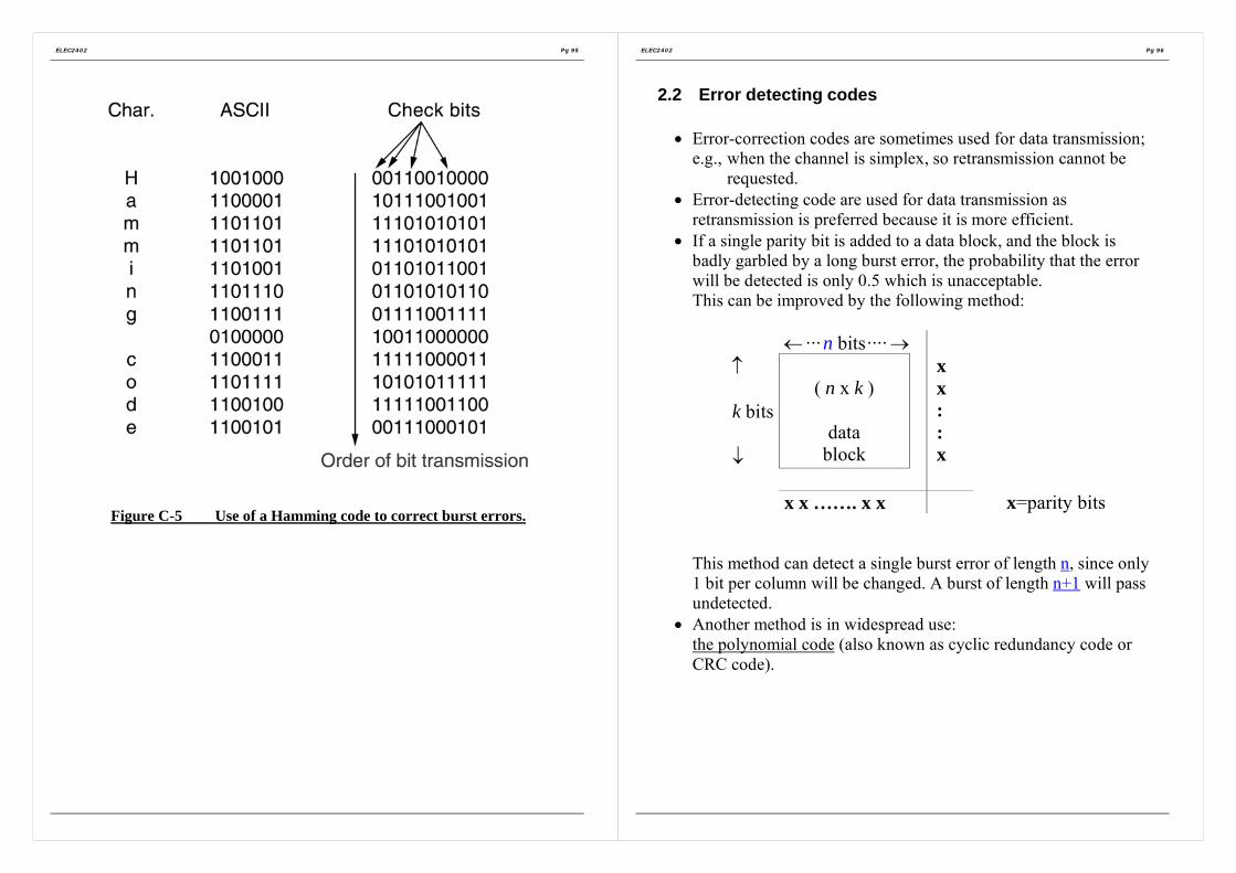
ELEC2402 Pg 95
Figure C-5 Use of a Hamming code to correct burst errors.
ELEC2402 Pg 96
2.2 Error detecting codes
• Error-correction codes are sometimes used for data transmission;e.g., when the channel is simplex, so retransmission cannot be
requested.• Error-detecting code are used for data transmission as
retransmission is preferred because it is more efficient.• If a single parity bit is added to a data block, and the block is
badly garbled by a long burst error, the probability that the errorwill be detected is only 0.5 which is unacceptable.This can be improved by the following method:
← ···n bits···· →↑
k bits
↓
( n x k )
datablock
xx::x
x x ……. x x x=parity bits
This method can detect a single burst error of length n, since only1 bit per column will be changed. A burst of length n+1 will passundetected.
• Another method is in widespread use:the polynomial code (also known as cyclic redundancy code orCRC code).

ELEC2402 Pg 97
Polynomial code (Cyclic Redundancy Code or CRC code)• Polynomial codes are based upon treating bit strings as
representations of polynomials with coefficients of 0 and 1 only.e.g. codeword 110 001 can be represented by
polynomial 5 4 3 2 1 01 1 0 0 0 1x x x x x x+ + + + +5 4 1x x= + +
• The basic idea of the polynomial code method is to append achecksum (the remainder in this case) to the end of the dataframe in such a way that the polynomial represented by thechecksum frame is divisible by G(x). {also refer to Figure C-6}
When the receiver gets the checksum frame, it tries dividing it byG(x). If there is a remainder, there has been a transmission error.
Where G(x) = generator polynomial(the sender and receiver must agree upon the same G(x)in advanced)
ELEC2402 Pg 98
Figure C-6 Calculation of the polynomial code checksum.
Note: Subtraction is implemented by XOR.
Append to the message
message
Append 0000to the message

ELEC2402 Pg 99
The algorithm for computing the checksum is as follows: {also referto Figure C-6}
(i) Let r be the degree of G(x). Append r zero bits to the low-order end of the data frame, so it now contains m+r bits, andcorrespond to the polynomial ( )rx m x .where m(x) = message polynomial of m bits.
(ii) Divide the bit string corresponding to ( )rx m x by the bit stringcorresponding to G(x) using mod-2 division, (i.e., uses binaryaddition and subtraction with no carries, which is just theeXclusive-OR (XOR) operation).
(iii)Subtract the remainder (which is always r or fewer bits) fromthe bit string corresponding to ( )rx m x using modulo 2subtraction. (This is equivalent to appending the remainder tothe end of the original data message). The result is thechecksum frame to be transmitted called its polynomial T(x).
For example: (In the base 10 system)19
10941 21027810941100868984692399
Then by subtracting the remainder 2399 off from 210278:
210278- 2399207879
Equal to 207879 is divisible by 10941And 207879 is to be transmitted.
ELEC2402 Pg 100
Implementation of a hardware circuit for calculation of CRC
The CRC process can be represented by a dividing circuit consistingof XOR gates and a shift register. The shift register is a string of 1-bitstorage devices.
The circuit is implemented as follows:1. The register contains n-k bits, equal to the length of the FCS.2. There are up to n-k XOR gates.3. The presence or absence of a gate corresponds to the presence
or absence of a term in the divisor polynomial, P(X), excludingthe terms 1 and Xn-k.
The architecture of a CRC circuit is explained by first considering anexample, which is illustrated in
Figure C-7. In this example, the follow is used:Data D = 1010001101; D(X) = X9 + X7 + X3 + X2 + 1Divisor P = 110101; P(X) = X5 + X4 + X2 + 1 = G(x), say.
As shown in Figure C-7(a) the CRC generating process begins withthe shift register cleared (all zeros). The message, or dividend, is thenentered, one bit at a time, starting with the most significant bit.

ELEC2402 Pg 101
+
+
+
++
+
+
+
Figure C-7 Circuit with Shift Registers for Dividing by the PolynomialX5+X4+X2+1
At the receiver, the same logic is used. As each bit of M arrives, it isinserted into the shift register. If there have been no errors, the shiftregister should contain bit pattern for R (the FCS) at the conclusion ofM. The transmitted bits of R now begin to arrive, and the effect is tozero out the register so that, at the conclusion of reception, the registercontains all 0s.
X4 X2
ELEC2402 Pg 102
Now, let’s consider the power of this method: what kinds of errorwill be detected?
• Imagine that a transmission error occurs, the received polynomialbecomes ( ( ) ( ))T x E x+ instead of ( )T x only.
• The receiver performs( ) ( ) ( ) ( ) ( )
( ) ( ) ( ) ( )T x E x T x E x E x
G x G x G x G x+
= + =
• Thus those errors corresponding to be polynomial ( )E x suchthat
( ) 0 ( ) ( ) ( )( )
E x E x G x Q xG x
= ⇒ = ⋅
will not be detected.Thus our interest is to find what kind of E(x) that is not divisibleby G(x), i.e., detectable error bit pattern.
• Single-bit errorA single-bit error corresponds to ( ) iE x x= , where i determineswhich bit is in error.If ( )G x contains two or more terms (e.g. 15 1x + ), it will neverdivide ( )E x .i.e., all single-bit errors will be detected.
a factor
0
transmitted polynomial error polynomial

ELEC2402 Pg 103
• Two isolated single-bit error
A two-isolated single-bit error corresponds to( ) , where
( 1)
i j
j i j
E x x x i jx x −
= + >
= +If we assume that ( )G x is not divisible by x, a sufficient conditionfor all double errors to be detected is that
( )G x does not divide 1kx +for any k up to the maximum value of i-j (i.e. up to the maximumframe length).
Simple, low-degree polynomials that five protections to long framesare known.e.g. 15 14( 1)x x+ + will not divide 1kx + for any k below 32768.
• Odd number of bits in error
Corresponding to E(x) contains an odd number of term
e.g.,5 2 2( ) 1 but not ( ) 1E x x x E x x= + + = +
There is no polynomial with an odd number of terms that has( 1)x + as factor in the modulo 2 system.By making ( 1)x + a factor of ( )G x , we can detect all errorsconsisting of an odd number of error bits.
ELEC2402 Pg 104
• Burst error of length <= rA polynomial code with r check bits will detect all burst error oflength <= ri.e., a burst error of length k can be represented by
( ) ( 1)i i kE x x x −= + +… ,where i determines how far from the right hand end of thereceived frame the burst is located.If G(x) contain an 0X term (i.e., 1), it will not have iXas a factor, so if the degree of the parenthesizedexpression is less than the degree of G(x), the remaindercan never be zero.
Probability of undetected bad frames
• If the burst length is (r+1),the remainder of the division by G(x) will be zero if and only ifthe burst is identical to G(x).Thus, by definition of a burst, the first and the last bits must be 1 ,so whether it matches G(x) depends on the (r-1) intermediate bits.If all combinations are equally likely, the probability of such an
incorrect frame being accepted as valid is11( )
2r−
.
• It can also be shown that when an error burst longer than (r+1)bits occurs, or several short bursts occur, the probability of a bad
frame getting through undetected is1( )2
r, assuming that all bit
patterns are equally likely.

ELEC2402 Pg 105
Three polynomials have become international standard
12 11 3 2 1
16 15 2
16 12 5
CRC-12 1CRC-16 1
CRC-CCITT 1
x x x x xx x xx x x
= + + + + +
= + + +
= + + +
All three ( )G x s contain ( 1)x + as a prime factor.
CRC-12CRC-12 is used when the character length is 6 bits.
CRC-16 and CRC-CCITTA 16-biut checksum such as CRC-16 or CRC-CCITT, detects allsingle and double errors, all errors with an odd number of bits, allburst error of length 16 or less,
99.997% of 17 bit error bursts99.998% of 18 bit and longer bursts.
Notice that simple shift register circuit can be used to implement andconstruct, to compute and verify the checksums in hardware. Thishardware is nearly always used in practice.
ELEC2402 Pg 106
3. Elementary Data link protocols
• As far as data link layer is concerned, the packet passed acrossthe interface to it from the network layer is pure data, every bit ofwhich is to be delivered to the destination’s network layer.
The fact that the destination’s network layer may interpret part ofthe packet as a header is of no concern to the data link layer.
• Thus when the data link layer accepts a packet, it encapsulatesthe packet in a frame by adding a data link header and trailer to it.Thus a frame consists of embedded packet and some control(header) information.The frame is then transmitted top to the other data link layer.
• We will assume that there exist suitable library procedureto_phycisal_layer to send a frame andfrom_physical_layer to receive a frame. The transmittinghardware computes and appends the checksum, so that the datalink layer software need not worry about.e.g. the polynomial algorithm for error correction/detection
might be used.

ELEC2402 Pg 107
• When a frame arrives at the receiver, the hardware computes thechecksum.If the checksum is incorrect (i.e., there was a transmission error),the data link layer is so informed (event = checksum error). If theinbound frame arrived undamaged, the data link layer is alsoinformed (event = frame arrival), so it can acquire the frame forinspection using from_physical_layer.
• As soon as the receiving data link has acquired an undamagedframe, it checks the control information in the header, and ifeverything is all right, the packet portion is passed to the networklayer. Under no circumstances is a frame header ever given to anetwork layer.
• The reason why the network layer must never be given any portof frame header is to keep the network and the data link protocolscompletely separate.Thus, providing a rigid interface between network layer and datalink layer greatly simplifies the software design becausecommunication protocols in different layers can evolveindependently.
ELEC2402 Pg 108
Figure C-8 Some definitions needed in the protocols to follow. Thesedefinitions are located in the file protocol.h (For Referenece only)
#define MAX_PKT 1024 /* determines packet size in bytes */
typedef enum {false, true} boolean; /* boolean type */typedef unsigned int seq_nr; /* sequence or ack numbers */typedef struct {unsigned char data[MAX_PKT];} packet; /* packet definition */typedef enum {data, ack, nak} frame_kind; /* frame_kind definition */
typedef struct { /* frames are transported in this layer */frame_kind kind; /* what kind of a frame is it? */seq_nr seq; /* sequence number */seq_nr ack; /* acknowledgement number */packet info; /* the network layer packet */} frame;
/* Wait for an event to happen; return its type in event. */void wait_for_event(event_type *event);
/* Fetch a packet from the network layer for transmission on the channel. */void from_network_layer(packet *p);
/* Deliver information from an inbound frame to the network layer. */void to_network_layer(packet *p);
/* Go get an inbound frame from the physical layer and copy it to r. */void from_physical_layer(frame *r);
/* Pass the frame to the physical layer for transmission. */void to_physical_layer(frame *s);
/* Start the clock running and enable the timeout event. */void start_timer(seq_nr k);
/* Stop the clock and disable the timeout event. */void stop_timer(seq_nr k);
/* Start an auxiliary timer and enable the ack_timeout event. */void start_ack_timer(void);
/* Stop the auxiliary timer and disable the ack_timeout event. */

ELEC2402 Pg 109
- A frame is composed of four fields:
frame kind seq ack info
Frame header Actual Data
kind: to indicate whether or not there are any data in theframe, because some of the protocol distinguish framescontaining exclusively control information from thosecontaining data as well.
seq: used for sequence numbers
ack: used for acknowledgements.
info: the info field of a data frame contains a single packet;(The info field of a control frame is not used).A more realistic implementation would use a variable-length info field, omitting it altogether for controlframes.
ELEC2402 Pg 110
3.1 An unrestricted simplex protocol
Assumption:
a) Simplex: one direction transmission only.
b) Both the transmitting and receiving network layers are alwaysready.
c) Processing time can be ignored.
d) Infinite buffer space is available.
e) The communication channel between the data link layers neverdamages or loses frames.
Thus this is an unrealistic protocol.

ELEC2402 Pg 111
Figure C-9 An unrestricted simplex protocol. (for reference only)
ELEC2402 Pg 112
3.2 A simplex stop-and wait protocol
Figure C-10 Stop-andWait Automatic Repeat Request (ARQ)
Assumption
• Now we remove the most unrealistic assumption used in previousprotocol in 3.1; i.e., the ability of the receiving network layer toprocess incoming data infinitely fast (or equivalently havinginfinite buffer space in the receiving data link layer)
• The communication channel is still assumed to be error free.
• The data traffic is still simplex.
The main problem we have to deal with here is how to prevent thesender from flooding the receiver with data faster than the receiver isable to process it.
Time

ELEC2402 Pg 113
Figure C-11 A simplex stop-wait protocol. (for reference only)
ELEC2402 Pg 114
3.3 A simplex protocol for a noisy channel
• Now let’s consider the realistic situation of a communicationchannel that makes errors. Frames may be either damaged or lostcompletely. However, we assume that if a frame is damaged intransit, the receiver hardware will detect this when it computesthe checksum. If the frame is damaged in such a way that thechecksum is nevertheless correct, an exceedingly unlikelyoccurrence, this protocol (and all other protocols) can fail. (i.e.,deliver on incorrect packet to the network layer).
• Remember that it is the task of communication subnet to provideerror free, transparent communication between network layers.To see what might go wrong !!The network layer on machine A gives a series of packets to itdata link layer, which must ensure that an identical series ofpackets are delivered to the network layer on machine B by itsdata link layer.In particular, network layer on B has no way of knowing that apacket has been lost or duplicated, so the data link layer mustguarantee that no combination of errors, no matter how unlikely,can cause a duplicate packet to be delivered to a network layer.

ELEC2402 Pg 115
Consider the potential problem: !!
Machine A Machine B
packet
Acknowledgement lost
Duplicate packet
Consider the following scenario:1. The network layer on A fives packet 1 to its data link layer. The
packet is correctly received at B and passed to the network layeron B. B sends an acknowledgement frame back to A.
2. The acknowledgement frame gets lost completely. It just neverarrives at all. Life would be a great deal simpler if the channelonly mangled and lost data frames and not control frames, butsad to say, the channel is not very discriminating
3. The data link layer on A eventually times out. Not havingreceived an acknowledgement, it (incorrectly) assumes that itsdata frame was lost or damaged and sends the frame containingpacket 1 again.
4. The duplicate frame also arrives at data link layer on B perfectlyand is unwittingly passed to the network layer there. If A issending a file to B, part of the file will be duplicated (i.e., thecopy of the file made by B will be incorrect and the error will nothave been detected.) In other words, the protocol will fail.
Solution:In order to distinguish a frame of the first-time transmission fromretransmission, the sender puts a sequence number in the header ofeach frame it sends.
Time
ELEC2402 Pg 116
Figure C-12 A positive acknowledgement with retransmission protocol.(for reference only)
As the acknowledgement frames will just be dummy, we will assumea strict alternation of sender and receiver. (In fact, theacknowledgement frames contains information in other protocols,such as sliding window).

ELEC2402 Pg 117
4. Sliding Window Protocols
• In the previous protocols, data frames were transmitted in onedirection only, i.e. simplex.
• In most practical situation, there is a need for transmitting data inboth directions, e.g. piggybacking
PiggybackingWhen a data frame arrives, instead of immediately sending aseparate control frame, the receiver restrains itself and waits untilthe network layer passes it the next packet. The acknowledgementis attached to the outgoing data frame (using the “ack” field in theframe header).In effect, the acknowledgement gets a free ride on the next outgoingdata frame.The technique of temporarily delaying outgoing acknowledgementso that they can be hooked onto the next outgoing data frame isknown as piggybacking.
• The principal advantage of piggybacking over having distinctacknowledgement frames is a better use of the available channelbandwidth. The “ack” field in the frame header only costs a dewbits, whereas a separate frame would need a header, theacknowledgement, and a checksum.
In addition, fewer frames sent means fewer “frame arrived”interrupts, and perhaps fewer buffers in the receiver, dependingon how the receiver’s software is organized.
• Piggybacking also introduces a complication not present withseparate acknowledgement.How long should the data link layer wait for a packet onto whichto piggyback the acknowledgement?Waiting a fixed number of milliseconds!! i.e., if a new packetarrives quickly, the acknowledgement is piggybacked onto it;
ELEC2402 Pg 118
otherwise, if no new packet has arrived by the end of this timeperiod, the data link layer just sends a separate acknowledgementframe.
• In addition to it being only simplex, protocol 3 in the previoussection can deadlock if the sender times out too early.
• It would be nicer to have a protocol that remained synchronizedin the face of any combination of garbled frames, lost frames,and premature timeouts. The next three sliding window protocolsare all highly robust and continue to function properly even underpathological conditions. The three differ among themselves interms of efficiency, complexity, and buffer requirements.
• The essence of all sliding window protocol is that at any instantof time, the sender maintains a list of consecutive sequencenumber s corresponding to frames it is permitted to send. Theseframes are said to fall within the sending window.Similarly, the receiver also maintains a receiving windowcorresponding to frames it is permitted to accept. The sender’swindow and the receiver’s window need not have the same lowerand upper limits, or even have the same size.
However, the protocol must deliver packets to the destinationnetwork layer in the same order that they were passed to the datalink layer on the sending machine.
• The sequence numbers within the sender’s window representframes sent but as yet not acknowledged.Whenever a new packet arrives from the network layer, it isgiven the next highest sequence number, and the upper edge ofthe window is advanced by one. When an acknowledgementcomes in, the lower edge of the window is advanced by one.
In this way the window continuously maintains a list ofunacknowledged frames.

ELEC2402 Pg 119
• Since frames currently within the sender’s window mayultimately be lost or damaged in transit, the sender must keep allthese frames in its memory for possible retransmission.
Thus if the maximum window size is n, the sender needs nbuffers to hold the unacknowledged frames.
If the window ever grows to its maximum size, the sending datalink layer must forcibly shut off the network layer until anotherbuffer becomes free.
• The receiving data link layer’s window corresponds to the framesit may accept.
Any frame falling outside the window is discarded withoutcomment.
When a frame whose sequence number is equal to the lower edgeof the window is received, it is passed to the network layer, anacknowledgement is generated, and the window is rotated by one.
Unlike the sender’s window, the receiver’s window alwaysremains at initial size.
Note that a window size of 1 means that the data link layer onlyaccepts frames in order, but for larger windows this is not so.
The network layer, in contrast, is always fed data in the properorder, regardless of the data link layer’s window size.
ELEC2402 Pg 120
Figure C-13. A sliding window of size 1, with a 3-bit sequence number. (a)Initially. (b) After the first frame has been sent. (c) After the first frame
has been received. (d) After the first acknowledgement has been received.
Note that window size ≠ max. Sequence number

ELEC2402 Pg 121
Figure C-14. Sliding-Window Depiction
Figure C-15. Example of a Sliding-Window Protocol
ELEC2402 Pg 122
4.1 A one bit sliding window protocol
- A sliding window protocol with a maximum window size of 1uses stop-and-wait, since the sender transmits a frame and waitsfor its acknowledgement before sending the next one. (as depictedin Figure C-16)
• Normally one of the two data link layer goes first. The startingmachine fetches the first packet from its network layer, buildsa frame from it, and sends it.
• When this (or any) frame arrives, the receiving data link layerchecks to see if it is duplicated. If the frame is the oneexpected, it is passed to the network layer and the receiver’swindow is slid up.
• The acknowledgement field contains the number of the lastframe received without error. If this number agrees with thesequence number of the frame the sender is trying to send, thesender knows it is done with the frame stored in buffer and canfetch the next packet from its network layer.
If the sequence number disagrees, it must continue trying tosend the same frame. Whenever a frame is received, a frame isalso sent back.
- However, a peculiar situation arises if both sides simultaneouslysend an initial packet. This synchronization difficulty is illustratedby Figure C-17.

ELEC2402 Pg 123
Figure C-16 A 1-bit sliding window protocol. (for reference only)
ELEC2402 Pg 124
(a) normal operation of the protocol (b) the peculiar situation.
Figure C-17 Two scenarios for protocol 4. (a) Normal case. (b)Abnormal case. The notation is (seq, ack, packet number). An asterisk
indicates where a network layer accepts a packet.
(a) : If B waits for A’s first frame before sending one of its own, thesequence of events is shown in (a), and every frame is accepted.Each frame arrival brings a new packet for the network layer;there are no duplicates.
(b) : If A and B simultaneously initiate communication, their firstframes cross, and the data link layers then get into situation (b).Half of the frames contain duplicates, even though there are notransmission errors.
Normal Abs-normal

ELEC2402 Pg 125
4.2 A protocol using go back n
• Until now we have made the tacit assumption that thetransmission time required for a frame to arrive at the receiverplus the transmission time for the acknowledgement to comeback is negligible. Sometimes this assumption is parentally false.In these situations the long round-trip time can have importantimplications for the efficiency of the bandwidth utilization.e.g. consider a 50kb/s satellite channel with 1 500msec round-
trip propagation delay. Let’s imagine trying to use protocol4 to send 1000-bit frames via the satellite. At time t=0 thesender starts sending the first frame. At t=20msec the framehas been completely sent. Not until t=500/2+20=270 msechas the frame fully arrived at the receiver, and not untilt=270+250=t=520 msec has the acknowledgement arrivedback at the sender, under the best of circumstances (nowaiting in the receiver and a short acknowledgement frame).This means that the sender was blocked during 500/520 or96% of the time (i.e., 4% only of the available bandwidthwas used).
Clearly, the combination of a long transit time, high bandwidthand short frame length is disastrous in terms of efficiency.
• This problem can be viewed as a consequence of the rulerequiring a sender to wait for an acknowledgement beforesending another frame.
ELEC2402 Pg 126
If we relax that restriction, much better efficiency can be achieved.Basically the solution lies in allowing the sender to transmit up toW frames before blocking, instead of just 1.With an appropriate choice of W the sender will be able tocontinuously transmit frames for a time equal to the roundtriptransmit time without filling up the window.
• In the previous example, W≥26 frames. The sender beginssending frame 0 as before. By the time it has finished sending 26frames, at time t=520msec, the acknowledgement for frame 0will have just arrived. Thereafter, acknowledgement will arriveevery 20 msec, so the sender always get permission to continuejust when it needs it. At all time, 25 or 26 unacknowledgedframes are outstanding. Put in other terms, the sender’smaximum window size is 26.
• This technique is known as pipelining.
• Pipelining frames over an unreliable communication channelraises some serious issues.
1) What happens if a frame in the middle of a long stream isdamaged? Large numbers of succeeding frames will arriveat the receiver before the sender even finds out that anythingis wrong.
2) When a damaged frame arrives at the receiver, it obviouslyshould be discarded, but what should the receiver do with allthe correct frames following it? Remember that thereceiving data link layer is obligated to hand packets to thenetwork layer in sequence.

ELEC2402 Pg 127
There are 2 basic approaches to dealing with errors in the presence ofpipelining (a) go back n
(b) selective repeat
(a) Go back nFor the receiver it is simply to discard all subsequent frames,sending no acknowledgement. This strategy corresponds to areceive window of size 1. In other words, the data link layerrefuses to accept any frame except the next one it must give tothe network layer.If the sender’s window fills up before the timer runs out, thepipeline will begin to empty. Eventually, the sender will time outand retransmit all unacknowledged frames in order, starting withthe damaged or lost one.This approach, shown in Figure C-18(a), can waste a lot ofbandwidth if the error rate is high.
(b) Selective repeatThe receiving data link layer store all the correct framesfollowing the bad one. When the sender finally notices thatsomething is wrong, it just retransmits the one bad frame, not allits successors, as shown in Figure C-18(b).
If the second try succeeds, the receiving data link layer will nowhave many correct frames in sequences, so they can all be handedoff to the network layer quickly and the highest numberacknowledged.
This strategy corresponds to a receiver window layer than 1. Anyframe within the window may be accepted and buffered until allthe preceding ones have been passed to the network layer. Thisapproach can require large amounts of data link layer memory ifthe window is large.
ELEC2402 Pg 128
Figure C-18 (a) Effect of an error when the receiver window size is 1. (b)Effect of an error when the receiver window size is large.
Error
Error

ELEC2402 Pg 129
• These two alternative approaches are trade-off betweenbandwidth and data link layer buffer space.
• Figure C-19 shows a pipelining protocol in which the receivingdata link layer only accepts frames in order; frames following anerror are discarded.In this protocol, for the first time, we have now dropped theassumption that the network layer always haws an infinite supplyof packets to send. When the network layer has a packet it wantsto send, it can cause a network_layer_ready event tohappen. However, in order to enforce the flow control rule of nomore than MAX_SEQ unacknowledged frames outstanding at anytime, the data link must be able to prohibit the network layerfrom brothering it with more work. The proceduresenable_network_layer anddisable_network_layer perform this function.
ELEC2402 Pg 130

ELEC2402 Pg 131
Figure C-19 A sliding window protocol using go back n. (for referenceonly)
ELEC2402 Pg 132
• Because this protocol (5) has multiple outstanding frames, itlogically needs multiple timers, one per outstanding frame. Eachframe times out independently of all the other ones.
• As an illustration of how the timers could be implemented,consider the example shown in Figure C-20.
Figure C-20 Simulation of multiple timers in software.
• In Figure C-20, we assume that the clock ticks every 100 msec.
• Initially, the real time is 10:00:00.0 and there are three timeoutspending at 10:00:00.5, 10:00:01.3 and 10:00:01.9.
• Every time the hardware clock ticks, the real time is updated andthe tick counter at the head of the list is decremented. When thetick counter becomes zero, a timeout is caused and the noderemoved from the list, as shown in Figure C-20(b).
• Although this organization requires the list to be scanned whenstart_timer or stop_timer is called, it does not requiremuch work per tick. In protocol 5, both of these routines havebeen given a parameter, indicating which frame is to be timed.

ELEC2402 Pg 133
4.3 A protocol using selective repeat
• Protocol 5 works well if errors are rare, but if the line is poor itwastes a lot of bandwidth on retransmitted frames.
• An alternative strategy to handling errors is to allow the receiverto accept and buffer the frames following a damaged or lost one.Figure C-21 illustrates the last, and most general protocol. Thisprotocol does not discard frames merely because an earlier framewas damaged or lost.
• The receiver has a buffer reserved for each sequence numberwithin its window. Whenever a frame arrive, it sequence numberis checked by the function “between” to see if it falls within thewindow. If so, and if it has not already been received, it isaccepted and stored. This action is taken without regard towhether or not it contains the next packet expected by thenetwork layer. Of course, it must be kept within the data linklayer and not passed to the network until all the lower numberedframes have already been delivered to the network layer in thecorrect order.
ELEC2402 Pg 134

ELEC2402 Pg 135
Figure C-21 A sliding window protocol using selective repeat. (forreference only)
ELEC2402 Pg 136
The potential failure
A potential problem is that after the receiver advanced its window, thenew range of valid sequences overlapped the old one. The followingbatch of frames might be either duplicated (if all theacknowledgement were lost), or new ones (if all the acknowledgementwere received). The poor receiver has no way of distinguishing thesetwo cases.
Solution:The solution lies in making sure that after the receiver has advancedits window, there is no overlap with the original window.
To ensure that there is no overlap, the maximum window size shouldbe at most half the range of the sequence numbers.
e.g. if 4 bits are used -> range 0...15,only 8 unacknowledged frames should e outstanding at any instant.
That way, if the receiver has just accepted frames 0 through 7 andadvanced its window to permit acceptance of frames 8 through 15, itcan unambiguously tell if subsequent frames are retransmission 90though 7) or new ones (8 through 15). In general, the window size forprotocol 6 will be (MAX_SEQ+1)/2.
• Thus the number of buffers needed is equal to the window size,not the range of sequence number.
• The number of timers needed is equal to the number of buffers(i.e. window size), not the size of the sequence space. Effectively,there is a timer associated with each buffer. When the timer runsout, the contents of the buffer are retransmitted.

ELEC2402 Pg 137
• Protocol 6 uses a more efficient strategy than protocol 5 fordealing with errors.Whenever the receiver has reason to suspect that an error hasoccurred, it sends a negative acknowledgement (NAK frameback to the sender. Such a frame is a request for retransmissionof the frame specified in the NAK.There are two cases when the receiver should be suspicious: adamaged frame has arrived or a frame other than the expectedone arrived (potential lost frame). To avoid making multiplerequests for retransmission of the same lost frame, the receivershould keep track of whether a NAK has already been sent for agiven frame.The variable no_nak in protocol 6 is true if no NAK has beensent for frame expected. If the NAK gets mangled or lost, no realharm is done, since the sender will eventually time out andretransmit the missing frame anyway.
ELEC2402 Pg 138
Timer administration
• If the turnaround time (the time required for a frame to propagateto the destination and have the acknowledgement come back) isnearly constant, the sender can adjust its timer to be just slightlylarger than the normal time interval between sending a frame andreceiving its acknowledgement.
• However, if this time is highly variable, the sender is faced withchoice of either
(a) Setting the interval to a small value and risking unnecessaryretransmissions, thus wasting bandwidth;
or(b) Setting the interval to a large value, and going idle for a
long period after an error, thus also wasting bandwidth.
• Variable turnaround time is a problem here. In general, wheneverthe standard deviation of the acknowledgement interval is smallcompared to the interval itself, the timer can be sent “tight” andNAKs are not useful.Otherwise, the timer must be sent “loose” and NAKs canappreciably speed up retransmission of lost or damaged frames.

ELEC2402 Pg 139
Examples of negative acknowledgements and retransmissions
• Can be implemented in a number of ways:a) Implicit rejectb) Selective reject (SREJ)c) Reject (REJ) or Go-Back-Nd) Selective reject / reject (SREJ/REJ)
Let’s defineN(S): sequence number of transmitted frameN(R): sequence number of the acknowledged frame(???TODO).
Acknowledges all frames up to N(R)-1
(a) Implicit rejectIt uses the N(R) value to acknowledge all preceding frames andrequest the retransmission of frame whose N(S) value equals thevalue in N(R).
Suitable for half duplex link.
(b) Selective reject (SREJ)It requires that only the damaged or lost frame to be retransmitted.
(c) Reject (REJ) or go-back-NNot only the lost or damaged frame to be retransmitted, but allsucceeding frames also retransmitted.
ELEC2402 Pg 140
(d) Selective reject-reject (SREJ-REJ)(The disadvantage of selective reject SREJ is the requirementthat only one selective reject frame can be outstanding at a timeas depicted in Figure C-23)
As depicted in Figure C-24, refer to the figure:SREJ-REJ performs like SREJ except that once an error isdetected, it waits to verify the next frame as correct beforesending SREJ.
If the receiver detects the loss of two contiguous frames, it sendsa REJ instead of SREJ and discards all subsequently receivedframes until the lost frame is received correctly.
Also if another frame error is detected prior to recovery of theSREJ condition, the receiver saves (stores) all frames receivedafter the first bad frame and discards frames received the secondbad frame until the first bad frame is recovered. Then a REJ isissued to recover the second frame and the other subsequentdiscarded frames.

ELEC2402 Pg 141
A
NAK 2
5 B4 3 2 1Error
(a) Frames 1 Through 5 Transmitted with an Error in Frame 2
A B2Retransmission
3
4
5
FramesHeldA B2
Retransmission
3
4
5
FramesHeld
(b) Selective Reject (SREJ)
A B
RetransmissionsNo Frames
Held5 4 3 2A B
RetransmissionsNo Frames
Held5 4 3 2
(c) Reject (REJ) or Go-Back-NFigure C-22 Retransmitting Erroneous Data
ELEC2402 Pg 142
Event Site A sends user dataframes with N(S) =
Site B responds with SREJframes with N(R) =
1 ........................ 5, 4, 3, 2, 1, 0 → ...................... A sends frames 0 through 52 ........................ ←SREJ 2, SREJ 4.......................... B sends two SREJs3 ................................................................................. A knows that SREJ 4,
NAKs 4 and ACKs allprevious frames such as 3.However, what about 2?
4, 2 = errors
Figure C-23 The problem with Multiple Selective Rejects (SREJs)
Events1. Site A has transmitted frames 0,1,2,3,4 and 5. If site B responds
with SREJ with N(R) = 2. This response frame acknowledges 0and 1, and requests the retransmission of 2.
2. However, let us suppose another SREJ frame were sent by site Bbefore the first SREJ condition cleared. Then multiple SREJscontradict the idea of the N(R) value acknowledging all thepreceding frames; as shown in Figure C-23.
Event
1 ........................ 5, 4, 3, 2, 1, 0 → ...................... A sends frames 0 through 52 .......................................... ←SREJ 2...................... Error detected in frame 23 ........................ 2→.................................................. B also detects error in
Frame 4. B stores 3 anddiscards 4 and 5
4 .......................................... ←REJ 4........................ B sends a REJ on 4 whichacknowledges 3
5 ........................ 5, 4→.............................................. A retransmits frames 4 and5
4, 2 = errors
Figure C-24 Using a Combination of Selective Reject and Reject i.e.(SREJ-REJ)

ELEC2402 Pg 143
5. Protocol performance
In principle, protocol 4,5 and 6 are equally good. They all serve toconvert a line makes errors into a virtual error free channel.
In practice they can differ substantially in terms of performance.
5.1 Performance of the Stop-and-Wait Protocol
• Many factors influence the efficiency of a protocol. Among themare whether frames are of fixed or variable length, whetherpiggybacking is used or not, whether the protocol is pipelined orstop-and-wait, whether the line is half or full-duplex, and thestatistical characteristics of the transmission errors.
• For example, for protocol 1, the channel efficiency is 100%because the sender just keeps sending full blast.However, the other protocols are less efficient because they mustoccasionally wait for acknowledgements, or transmit frames asecond time or more.
• As an example, let us analyze a one directional stop-and-waitprotocol with fixed-length frames and no piggybacking, such asprotocol 3.
The basic approach we will use to determine the channelefficiency of any protocol, is to determine how much bandwidthis actually tied up to send the statistically average frame, takingaccount of all its retransmissions and timeouts.
ELEC2402 Pg 144
For the derivation, we use the following notation:
A = Number of bits in an ACK frameC = Channel capacity in bpsD = Number of data bits per frameE = Probability of a bit being in errorF = D+H (total frame length)H = Number of bits in the frame headerI = Interrupt and service time + propagation delayL = Probability that a frame or its ACK is lost or damagedP1 = Probability that a data frame is lost or damagedP2 = Probability that an ACK frame is lost or damagedR = Mean number of retransmissions per data frameT = Timeout intervalU = Channel utilization (efficiency)W = Window size
i.e.,
a frame: H DF
an ACK frame: A

ELEC2402 Pg 145
• Now let us consider the effects of transmission errors.
Sender A Receiver BF bits (error & lost)
A+CI bits
Timeout = TC bitsF+CI bits
i.e., an unsuccessful transmission uses F CT+ bits;where T=timeout (sec.)
The total channel capacity used = ( ) ( 2 )R F CT F A CI+ + + +
Now: it remains to compute, R, the mean number of retransmissionsper data frame.
A frame is successful if both the data and acknowledgement arecorrectly received.The probability of success = 2 1(1- )(1- )P PThe probability of failure, 2 11- (1- )(1- )L P P=
The probability that exactly k attempts are needed-1(1- ) kL L=
(i.e., k-1 retransmissions)
This result yields:
Expected number of transmission per frame1
1 L=
−
Time
ELEC2402 Pg 146
Expected number of retransmission per frame 1LR
L=
−
Using this value of R, we arrive at a channel utilization given by
( )( ) ( 2 )1
DU L F CT F A CIL
=+ + + +
−
If the receiver’s service time has a low variance, the sender can set ittimeout interval T just above the time required for theacknowledgement to arrive:i.e.
2 2AT I CT A CIC
≈ + ⇒ ≈ +
Then the channel efficiency becomes
2 1
2 1
( )( ) ( ) (1 )( )1 1
11 (1 )(1 )( ) (1 )
11(1 )(1 ) ;
1
D DU L LF CT F CT F CTL L
DCT P PF
L FD P P F H DCTH D
H D
= =+ + + − +
− −
= =− −+
−
= − − = ++ +
+
The first factorD
H D+ = the loss due to header overhead;The 2nd factor 2 1(1- )(1- )P P = the loss due to error;
The 3rd factor1
1 CTH D
++
= the loss due to stop-and-wait.

ELEC2402 Pg 147
• Before considering the effects of errors, let us see what thechannel utilization would be for a perfect line. Surprisinglyenough, it can be far below 100%.
H DF
H DH DFSender A Receiver B
F/C + I
A/C + IA
=> ( ) ( )F AI IC C
+ + + = the time interval between the sender begins tosend a frame and the sender has processed the acknowledgementand is ready to send the next data frame.
The bandwidth occupied by this frame ( )F AC I IC C
= + + +
2 in unit of bitsF A CI= + +F H D= +∵
the channel efficiency = 2D
H D A CI+ + +
Thus, if the header H and acknowledgements A are negligible, thebandwidth low, and the propagation and service times I are short, thechannel utilization will be high; otherwise, not.
Time
ELEC2402 Pg 148
To proceed further, we need a model relating the probability of aframe’s being in error to its length.
To start with, let us make the (not terribly realistic) assumption thateach bit has a probability E of being in error, independent of thepreceding and succeeding bits. With this assumption and A=H we findthat the channel utilization is given by the formula:
1(1 ) (1 )1
H D HDU E E CTH DH D
+= − −+ +
+
1
2
as (1 ) (1 )
(1 ) (1 )
H D
H
P E
P E
+− = −
− = −
=> Then, what is the optimum frame size?
2 ( ) 0ln(1 )
du H CTD D H CTdD E
+= + + + =
−
with solution4( 1 1)
2 ( ) ln(1 )optH CTD
H CT E+
= + −+ −
If E is very small, ln(1- )E E≈ − and
optH CTD
E+
≈

ELEC2402 Pg 149
Note that H CT+ is the overhead due to headers and timeouts. Asthe transmission line quality improves (i.e., E->0 the optimum framesize optD increases, as it should.i.e., when E=0, optD -> as long a frame as possible;
when E is large, optD -> small.
To analyze the channel efficiency for frame sizes close to theoptimum, let optD X D= ⋅ ;So values of X close to 1 represent frames close to the optimum size.Now substitute optXD opt into the equation for U and make the
approximation (1 ) 1DE ED− ≈ − to get
1 ( )(1 2 ) 11 ( )
X H CT EU HEH CT E
X
− +≈ −
+ +
Note that actual measurements of error characteristics of telephonesystem show that errors do not befall individual bits at random.Instead, errors tend to come in bursts. Thus the model
1(1- ) (1- )H DP E += is not an accurate one.
Experimentally, it appears that 1 ( )P k H D α= + provides a better fit.Finding the optimum frame size and channel efficiency for this modelcan be done using the method shown above.
ELEC2402 Pg 150
5.2 Performance of the sliding window protocol
• To perform a simple analysis of sliding window protocols, let usassume that acknowledgements are piggybacked onto reversetraffic, so they can be ignored. Furthermore, let us assume thatinterrupt processing time is negligible, so I is equal to the one-way propagation time, τ. These assumptions simplify the analysisconsiderably.
F
Sender A Receiver BF/C
2I.
.
.
.
.
.
Window size of W
We will first analyze an error-free transmission channel;afterwards we will see how errors affect the performance.
• If the window is large enough, the sender can just keep going atfull speed because the acknowledgements get back before thesender’s window fill up.
That is, the frame transmission time isFC , so the sender may
continue for a timeFWC at which point it must stop if the first
frame has not yet been acknowledged. The firstacknowledgement can come back 2I after the first frame has been
transmitted so the acknowledgement arrives at 2F IC
+ .
Time

ELEC2402 Pg 151
The transmitter will be able to run continuously if
2F FW IC C
≥ + .
This inequality may also be solved for W giving:
Case 1:2ICw IF
≥ + (large window, no errors)
Channel efficiencyDU
H D=
+
i.e., the channel runs at full speed, with the header H bits beingthe only overhead.
Case 2:21 ICWF
< + (small window, no errors)If the window is small, the sender will have to stop at some pointand wait for the first acknowledgement. Then it may send onemore frame, at which time the next acknowledgement arrives,
and so on. Each cycle takes 2F IC
+ and is good for or carried forW frames or WD data bits. Thus,
( 2 )
;21
21( )
WDUF IC
D W F H DICFF
D WICH D
H D
=+
= ⋅ = ++
= ⋅+ +
+
ELEC2402 Pg 152
Case 3:21 ICWF
≥ + (large window, with errors)
In the large window case, transmission is still continuous, exceptthat now extra frames must be sent to correct damaged frames.As we saw in the previous section, the expected number of
transmission per frame 11 L
=− , so to receive W frames without
errors, 1W
L− of them must be transmitted. Thus we have
.(1 )DU LH D
= −+
Case 4:21 ICWF
< + (small window, with errors)Similarly, with a small window, the channel efficiency U alsodrops by the same factor (1-L) due to retransmissions, i.e.,
(1 ) 21( )
D WU L ICH DH D
= ⋅ − ⋅+ +
+=============//=================
In the above models, the boundary between the large window and
small window cases comes when21 ICWF
= + .The time I is the one-way propagation time of the cable, so theproduct CI is the number of bits that can be sent in this time; i.e., CI isthe number of bits the cable can hold, or the cable can hold, or thecable length expressed in bits. Therefore CI
F is the cable length inframes W=1+(no. of frames it takes to fill up the cable in bothdirection).

ELEC2402 Pg 153
For an error free channel:
0 2 4 6 8 10Channel length in frames (CI/F)
0
0.2
0.4
0.6
0.8
1
Cha
nnel
utili
zatio
n Slidingwindow(W=7)
Stop-and-wait
(a)
0 2 4 6 8 10 12Window size (W)
0
0.2
0.4
0.6
0.8
1
Cha
nnel
utili
zatio
n
Cablelength
= 5 frames
Cabl
elen
gth=
3f ra
mes
Cab
lele
ngth
=1
fram
e
(b)Figure C-25 (a) Channel utilization as a function of cable length. (b)
Channel utilization as a function of window size. In both cases the headeroverhead is assumed to be 20 percent.
i.e., channel utilization depends on channel length in frame ( )CIF and
window size W.
• Example:
a 10Mb/s 1km LAN CI ~ 5- bits => CI/F << 1
a 64k b/s with 3,000km long CI~960 bits; for short framesthe cable will be severalfames long.
a satellite channel at 64kb/s withpropagation time of 270msec.
CI~17.280bits => CI/F >> 1
ELEC2402 Pg 154
6. Example Data link protocols
6.1 HDLC – High-Level Data Link Control
High Level Data Link Control (ISO 33009, ISO 4335)Old but still widely used.
As an international standard, HDLC caters for many networkconfigurations and applications.=> makes it the basis of many protocols (e.g. X.25 Packet
switched network, ISDN, LAN, ATM, PPP).
HDLC: Modes of OperationsHDLC defines 3 types of stations, 2 link configurations and 3operating modes.
Figure C-26 The three HDLC modes of operations

ELEC2402 Pg 155
Three types of stations
• Primary (Master) stationControls the operation of the data link. Issues commands.
• Secondary (Slave) stationOperates under the control of the primary station. Issues
responses.
• Combined stationOperates like primary and secondary. Issues command andresponses.
Two link configurations
• Unbalanced configurationOne primary and one secondary. Not all stations have the sameset of capabilities.
• Balanced configurationCombined stations with the same set of capabilities.
Three modes of data transfer
• Normal response mode (NRM)Unbalanced configuration.The primary may initiate data transfer to a secondary. But thesecondary can only transmit in response to a command from theprimary.The primary polls the secondary station(s) to respond.Can be used in shared medium configurations,
e.g. multi-drop.
ELEC2402 Pg 156
• Asynchronous response mode (ARM)Unbalanced configuration.The secondary may initiate data transfer not as a response to acommand from the primary. The asynchronous transmission fromsecondary stations means that there can only be one activesecondary station. However only the primary has the capability toinitialize the link, recover from errors and logically disconnectthe stations.
• Asynchronous balanced mode (ABM)Balanced configuration.Any of the combined stations may initiate data transfer. Nopolling is required. Therefore, more efficient. Used in full-duplexpoint-to-point links.
HDLC Frame Format
8 bits 8-16bits
8-16bits
Variable 16-32bits
8 bits
Flag01111110
ADDRESS Control Information FCS Flag01111110
Preamble, Postamble and inter-frame fills: Flags (01111110)
The frame is encoded with zero-insertion for data transparency.
Address Field: First byte (octet) but can extend to multiple bytes.For multiple-byte address,l.s.b. = 1 -> last byte of address field.

ELEC2402 Pg 157
Control field: 1 byte but can extend to 2 bytes.Used to define the function of the frame.
Information Field:Variable length.Used to convey user data.
FCS Field: Frame check sequence.16 bits FCS the degree of� G(x) = r = 16
16 12 5( ) 1G x x x x= + + +Can extend to 32 bits.
The maximum length of a frame is a system parameter, N1.
HDLC Control FieldThere are three types of frames which are identified by the format ofthe Control Field.
(1) Information Frame (I-frame)Used to convey user data.
(2) Supervisory Frame (S-frame)Used for error and flow control.No N(S). Piggyback N(R).
(3) Unnumbered Frame (U-Frame)Used for link management functions (e.g. setup, clear, operationmode).No N(S) nor N(R).
ELEC2402 Pg 158
Control Field: Modulo-8 (3-bit sequence number)
Type 1 2 3 4 5 6 7 8I-frame 0 N(S) P/F N(R)S-frame 1 0 S S P/F N(R)U-frame 1 1 M M P/F M M M
Bit 1 = 0 => I-frame
Bit 1 = 1 and Bit 2 = 0 => S-frame
(Bits 3 and 4 specify the supervisory functions.)
Bit 1 = Bit 2 = 1 U� -frame(Bits 3, 4, 6, 7 and 8 specify the unnumbered function modifier
bits.)
Control field: Modulo-128 (7-bit sequence number)
Type 1 2 3 4 5 6 7 8 9 10 11 12 13 14 15 16I-frame 0 N(S) P/F N(R)S-frame 1 0 S S 0 0 0 0 P/F N(R)U-frame 1 1 M M P/F M M M
The control field of I-frame and S-frame is composed of two bytes.
The supervisory function bits and the unnumbered function modifierbits define the HDLC commands and responses.

ELEC2402 Pg 159
Name C/R Description
Information (I-frame) C/R Exchange user dataSupervisory (S-frame) functionsdefined by Bits 3 and 4Receive Ready (RR) C/R Positive acknowledgement; ready to receiveReceive Not Ready (RNR) C/R Positive acknowledgement; not ready to
receiveReject (REJ) C/R Negative acknowledgement; go back NSelective Reject (SREJ) C/R Negative acknowledgement; selective
reject.Unnumbered (U-frame) functionsdefined by Bits 3, 4, 6, 7 and 8Set NRM (SNRM) C Set Normal Response ModeSet SARM (SARM) C Set Asynchronous Response ModeSet SABM (SABM) C Set Asynchronous Balanced ModeSet NRM Extended (SNRME) C Set Normal Response Mode; 7-bit sequence
numberSet SARM Extended (SARME) C Set Asynchronous Response Mode; 7-bit
sequence numberSet SABM Extended (SABME) C Set Asynchronous Balanced Mode;
7-bit sequence numberSet Initialization Mode (SIM) C Initialize link control functions in addressed
stationRequested Initialization Mode(RIM)
R Initialization need; requested for SIMcommand
Disconnect (DISC) C Terminate a logical link connectionDisconnect Mode (DM) R Indicate in disconnected modeRequest Disconnect (RD) R Request for DISC commandUnnumbered Poll (UP) C Solicit control informationReset (RSET) C Recovery; reset V(S) at the Tx station and
V(R) at the Rx stationExchange identification (XID) C/R Request / Report statusTest (TEST) C/R Exchange identical information fields for
testingFrame Reject (FRMR) R Report receipt of unacceptable frame.Command Reject (CMDR) R Report receipt of unacceptable command.Unnumbered Acknowledgement(UA)
R Acknowledge the reception and executionof set-mode, SIM or DISC command.
ELEC2402 Pg 160
HDLC Operations
HDLC: Link Set-up
The link set-up procedure starts with the transmission of one of the 6set-mode commands. The command is used to
• request link initialization• specify the operation mode• number of bits in a sequence number
Successful connection:
Unsuccessful connection:

ELEC2402 Pg 161
HDLC: Data Transfer
Exchange of user data can take place after link set-up. The proceduresof data transfer, flow control and error recovery follow the principlesthat have been discussed in the previous sections.
• Sliding window• Timeout• Retransmission
o Timeouto REJ for Go-Back-No SREJ for Selective-Reject
• Flow Control: RR and RNR• Acknowledgement:
o RR and RNRo Piggyback
In NRM, the secondary transmits I-frames under the control of theprimary. To initiate data transfer from a secondary, the primaryusually sends a UP (unnumbered poll) frame or a RR frame with thePoll bit set. The addressed secondary then sends a sequence of I-frames. The Final bit of the last I-frames is set to mark the end of thedata transfer.
ELEC2402 Pg 162
HDLC: Disconnect:
HDLC as an OSI LayerThe following is an example of using HDLC to support OSI. In thisexample, the data service is a non-confirm type.

ELEC2402 Pg 163
HDLC State Diagram Example
The following diagram shows an example of HDLC ABM statetransition diagram (incomplete).
Notation: Each arc is associated with the condition to transit to thenext state. The condition is composed of two parts separatedby a semi-colon. The first part is the incoming event and thesecond part is the result.
e.g. DL.CONNECT.req ; UA means “A primitive requesting forconnection was received and the UA frame has been sent”.
Figure C-27 An example of HDLC ABM state transition diagram.
ELEC2402 Pg 164
DLC: Multi-link Procedure (MLP)
The HDLC procedures discussed in the above sections are used fordata exchange over a single physical circuit. These procedures arecalled single link procedures (SLP). In order to have higher bandwidth,use multiple physical circuits.Multi-link procedures (MLP) are used for data exchange over thesemultiple parallel data links (SLPs).
The MLP exists as an added upper sublayer of the data link layer. AMLP must perform the functions of accepting data units from thenetwork layer, distributing them as frames across the available SLPsand re-sequencing the frames from SLPs into data units for delivery tothe network layer. A MLP frame is put in to the I-filed of a SLP I-frame for transmission. A MLP frame has two fields: 16-bit Multi-linkControl (MLC) field and variable Information field.

ELEC2402 Pg 165
6.2 The Data Link Layer in the Internet
The Internet consists of individual machines (hosts and routers) andthe communication infrastructure that connects them. Within a singlebuilding, LANs are widely used for interconnection, but most of thewide area infrastructure is built up from point-to-point leased lines.
Two point-to-point communication situations:• Organizations have one or more LANS along with a router.
The routers are interconnected by a backbone LAN. Alloutgoing connections go through one or two routers thathave point-to-point leased lines to distant routers.
• Home connections to the Internet using modems and dial-uptelephone lines
Figure C-28 A home personal computer acting as an Internet host.
Both router-router leased line connection and the dial-up host-routerconnection require point-to-point data link protocol on the line forframing, error control, and the other data link layer functions.=> PPP used in Internet
ELEC2402 Pg 166
PPP – The Point-to-Point Protocol (RFCs 1661, 1662 and 1663)
PPP handles error detection, supports multiple protocols, allows IPaddresses to be negotiated at connection time, permits authenticationand provides the following three features:
• A framing method that unambiguously delineates the end of oneframe and the start of the next one. The frame format alsohandles error detection.
• A link control protocol for bringing lines up, testing them,negotiation options, and bring them down again gracefullywhen they are no longer needed. This protocol is called LCP(Link Control Protocol). It supports synchronous andasynchronous circuits and byte-oriented and bit-orientedencoding.
• A way to negotiate network-layer options in a way that isindependent of the network layer protocol to be used. Themethod chosen is to have a different NCP (Network ControlProtocol) for each network layer support.
ELEC2402 Pg 167
Typical scenario of a home user calling up an ISP to make a homepc a temporary Internet host:
1. PC calls the provider router via a modem. A physicalconnection is established.
2. PC sends the router a series of LCP packets in the payload fieldof one or more PPP frames. These packets and their responsesselect the PPP parameters to be used.
3. Once the parameters have been agreed, a series of NCP packetsare sent to configure the network layer. Typically the PC wantsto run a TCP/IP protocol stack, it needs an dynamic IP address.The NCP for IP assigns the IP address.
4. Then the PC is now an Internet host and can send and receive IPpackets.
5. When the user is finished, NCP tears down the network layerconnection and frees up the IP address. Then LCP shuts downthe data link layer connection.
ELEC2402 Pg 168
The PPP Frame format:
Figure C-29 The PPP full frame format for unnumbered modeoperation.
Flag All PPP frames begin with the standard HDLC flagbyte (01111110), which is byte stuffed if it occurswithin the payload field.
Address Always set to binary value 11111111 to indicate thatall stations are to accept the frame. Using this valueavoids the issue of having to assign data linkaddresses.
Control Default is 00000011 which indicates an unnumberedframe. In other words, PPP does not provide reliabletransmission using sequence numbers andacknowledgements as the default.
Protocol Specifies what kind of packet is in the Payload field.Codes are defined for LCP,NCP, IP IPX, AppleTalk,and other protocols. The default size of the protocolfield is 2 bytes, but it can be negotiated down to 1byte using LCP.
Payload Variable length, up to some negotiated maximum,default length is 1500 bytes, if the length is notnegotiated using LCP during line setup.
Checksum Default is 2 bytes, but a 4 byte checksum can benegotiated.

ELEC2402 Pg 169
PPP communication phases:
Figure C-30 A simplified phase diagram for bringing a line up anddown.
The protocol starts with the line in the DEAD state. After physicalconnection is established, the line moves to ESTABLISH. LCP optionnegotiation begins, if successful, leads to AUTHENTICATE. Now thetwo parties can check on each other’s identities if desired. When theNETWORK phase is entered, the appropriate NCP protocol is invokedto configure the network layer. If the configuration is successfulOPEN is reached and the data transport can take place. When datatransport is finished, the line moves into the TERMINATE phase, andfrom there, back to DEAD when the carrier is dropped.
ELEC2402 Pg 170
Section D
The Medium Access Control SubLayer
1. The Channel Allocation Problem
2. Multiple access protocols
3. Ethernet

ELEC2402 Pg 171
Introduction
Access to the medium by multiple stations
Main applicationsShared medium peer-to-peer communication networks broadcastinginformation to every station.
Protocols specially defined for this kind of networks concern mainlywith the transmission of blocks of data over the shared medium whichcontains a broadcast channel (multi-access channel, random accesschannel).
Different protocols are used for networks with different shared mediaand different configurations. Therefore, in the multiple accessenvironments, there is a distinct function: controlling the access to theshared medium by multiple stations. It is better to have a sub-layer inthe data link layer to perform this function.
ELEC2402 Pg 172
1. The Channel Allocation Problem
To allocate a single broadcast channel among competing users.
(a) Static Channel Allocation in LANs (Local Area Network) andMANs (Metropolitan Area Network)
In this scheme, a user will be allocated a fix portion of thechannel (frequency band, time slot). It is suitable for networkswith uniform traffic (non-bursty traffic) among stations becauseno need to negotiate for access.
FDMA and TDMA are also the base technologies of multipleaccess networks.
(b) Dynamic Channel Allocation in LANs and MANs
There is no strict ordering of the contending stations to gainaccess to the channel. This may lead to contention and thusrequire another transmission.

ELEC2402 Pg 173
2. Multiple access protocols
i) ALOHA
(a) Aloha – does not require global time synchronization(b) Slotted Aloha - require global time synchronization
(a) Pure ALOHA• Basic Idea:
Let users transmit whenever they have data to be sent.If there is a collision (i.e. another user is transmitting at the sametime), the colliding frames will be damaged. Due to the feedbackproperty of broadcasting, a sender can always find out whetherits frame was destroyed by listening to the channel
Figure D-1 In pure ALOHA, frames are transmitted at completelyarbitrary times.
In pure ALOHA, frames are transmitted at completely arbitrarytimes.Whenever two frames try to occupy the channel at the same time(or even only a bit of frame is overlapped), there will be acollision and both will be garbled.
ELEC2402 Pg 174
(b) Slotted ALOHA• Divide time into discrete intervals, each interval corresponding to
one frame.• Each user required to transmit on slot boundaries.• Throughput =1/e or about 0.368, twice of pure ALOHA.
UserABCDEIn slotted ALOHA, each user required to transmit on slotboundaries.
Figure D-2 Throughput versus offered traffic for ALOHA systems.
Time
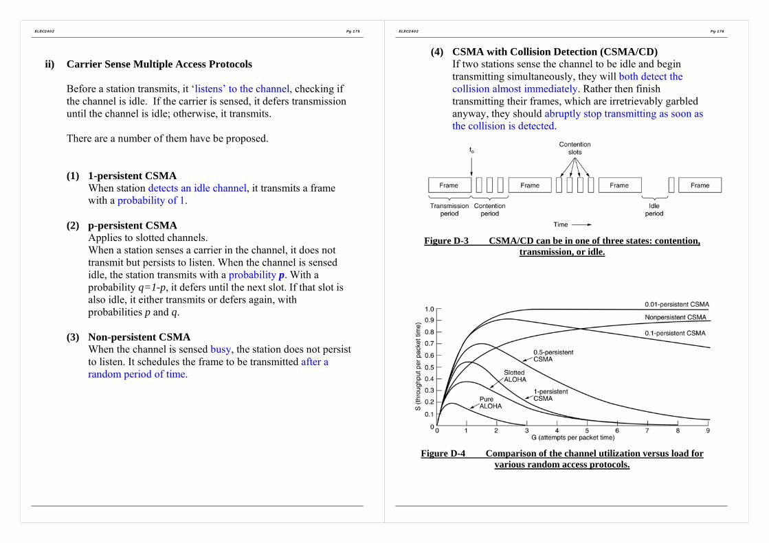
ELEC2402 Pg 175
ii) Carrier Sense Multiple Access Protocols
Before a station transmits, it ‘listens’ to the channel, checking ifthe channel is idle. If the carrier is sensed, it defers transmissionuntil the channel is idle; otherwise, it transmits.
There are a number of them have be proposed.
(1) 1-persistent CSMAWhen station detects an idle channel, it transmits a framewith a probability of 1.
(2) p-persistent CSMAApplies to slotted channels.When a station senses a carrier in the channel, it does nottransmit but persists to listen. When the channel is sensedidle, the station transmits with a probability p. With aprobability q=1-p, it defers until the next slot. If that slot isalso idle, it either transmits or defers again, withprobabilities p and q.
(3) Non-persistent CSMAWhen the channel is sensed busy, the station does not persistto listen. It schedules the frame to be transmitted after arandom period of time.
ELEC2402 Pg 176
(4) CSMA with Collision Detection (CSMA/CD)If two stations sense the channel to be idle and begintransmitting simultaneously, they will both detect thecollision almost immediately. Rather then finishtransmitting their frames, which are irretrievably garbledanyway, they should abruptly stop transmitting as soon asthe collision is detected.
Figure D-3 CSMA/CD can be in one of three states: contention,transmission, or idle.
Figure D-4 Comparison of the channel utilization versus load forvarious random access protocols.

ELEC2402 Pg 177
iii) Collision-Free Protocols
As the propagation time τ becomes larger, the detection time (2τ)becomes longer . This would impose serious performancedegradation if the frames are comparatively short (e.g. firer opticnetwork).
Bitmap-Map ProtocolThis is a distributed collision-free scheme. A contention periodconsists of exactly N slots according to the number of stations. Astation announces its intention to transmit by sending a ‘1’ duringthe contention slot corresponding to its station number. After thecontention period, every station knows all exactly which stationswant to transmit. Then the stations start to transmit one after theother according to their numerical order. Since every stationknows the exact order of transmission, therefore free of collisions.
Figure D-5 The basic bit-map protocol.
Marking a bit in a contention slot is like making a reservationbefore transmission starts. Therefore, this kind of protocols iscalled reservation protocol.
ELEC2402 Pg 178
Assume that time can be measured in terms of units of thecontention bit slot and that it takes d units to transmit a frame.
At light load (only one station transmits),
Efficiency=d
d N+
At heavy load (all stations transmit),
Efficiency= 1d
d +
Binary Countdown• The overhead in the bit-map protocol is 1 bit per station.
Therefore N bits is required for N station, so it does notscale well to networks with thousands of stations. If thereservation is made based on the binary addresses of thestations, the overhead bits can be redacted to 2log N
• There are only 2log N contention slots• Stations transmit ith bit of their address during ith contention
slot. Assume that ‘1’ dominates over ‘0’ (i.e. OR function).• Each station compares the resulting bit in ith contention slot
with its ith address bit. If equal, it continues with thecontention exercise. If no, it drops out of the race.
• This scheme favors stations with higher address numbers.They force those lower-numbered stations to drop out of therace.
• Overhead per frame = 2log N
• Efficiency =2log
dd N+

ELEC2402 Pg 179
(iv) Limited-Contention Protocols
Problem with collision protocols (CSMA)At light load, delay is low.As load increases, probability of collision increases => higherdelay.
Problem with collision-free protocolsAt light load, the delay is high.As load increases, the channel efficiency improves.
• Combine the beat properties of both:Use contention at light load and use collision-free at highload. ==> Limited-Contention protocols
Example: The Adaptive Tree Walk Protocol• When there is conflict, need to locate stations causing
conflicts and allocate channel accordingly. Linear search istime-consuming. Can use a tree walk algorithm to resolvecontention when conflict occurs.
• If there is a collision, the stations are recursively dividedinto groups until the conflict is resolved. (For binary tree,the number of groups is 2.) This splitting and searchingprocess is like climbing a tree in a depth first manner.
• Consider a binary tree structure. Each station is taken as aleaf on the tree. Stations are assigned contiguous binarynumbers. Each visited node in the tree corresponds to a slot.
1. Start from the root node which corresponds to Slot 0,during which all stations are permitted to acquire thechannel.If there is no collision, there is no station intending totransmit during this slot. Repeat this step (i.e. slot 0)again.
ELEC2402 Pg 180
2. If there is a collision in slot0, need to search for thecolliding stations into order to resolve conflict.Split the stations into two groups (left and rightsubtrees). This is like climbing the tree one leveltowards the leaves.Stations in the left sub-tree are those with ‘0’ as themost significant address bit. These stations are allowedto transmit in the next slot, slot 1.Stations in the right sub-tree are those with ‘1’ as themost significant address bit and are not allowed totransmit in slot 1.
3. If here is no collision in slot 1, further split thesubtrees into left and right sub-trees.Only those stations with ‘00’ as the m.s. address bitsare allowed to transmit in the next slot, slot 2. (This isequivalent to further climbing towards the leaves alongthe left sub-tree).If there is no collision in slot 1, only those stationswith ‘01’ as the m.s. address bits are allowed totransmit in the next slot, slot 2. this is equivalent tofinishing the search with the left sub-tree and goingback to climb (Search) the right sub-tree.
4. The above steps are repeated in a similar manner untilall the conflicts occurring in slot 0 have beencompletely solved.
0 1
00 01

ELEC2402 Pg 181
(v) Wavelength Division Multiple Access protocols(Similar concept to FDM)
• A fixed-wavelength receiver for listening to its own controlchannel.
• A tunable transmitter for sending on other stations’ controlchannels.
• A fixed-wavelength transmitter for outputting data frames.• A tunable receiver for selecting a data transmitter to listen to.
Figure D-6 Wavelength division multiple access.
ELEC2402 Pg 182
(vi) IEEE 802.11 - Wireless LAN
Based on cellular architecture.
Each cell is called a Basic Service Set, BSS, controlled by a basestation, known as access point, AP.
APs are connected together by a backbone network known asdistribution system, DS. e.g. Ethernet.
Basic access method: CSMA/CA (CSMA= Carrier SenseMultiple Access, CA = Collision Avoidance)
Figure D-7 Wireless LAN Architecture.

ELEC2402 Pg 183
where as MAC = Medium Access ControlFigure D-8 IEEE 802.11 Protocol Architecture.
ELEC2402 Pg 184
MACA (Multiple Access with Collision Avoidance):
In some wireless network, simultaneous transmissions areallowed as long as these transmissions are aimed at differentdestinations which are out of the range from one another.
Consider the following two cases in a wireless network:
(i) Hidden terminals
A can hear B and C, but B and C cannot hear (are hiddenfrom) each other.When B transmits to A, C does not know about this andtransmits. ==> collision.
(ii) Exposed terminals
B sends to A while C sends to D. These two pairs are indifferent areas.But C hears (is exposed to) B and so C backs offunnecessarily.

ELEC2402 Pg 185
CSMA/CA is not suitable for these situations because anyCSMA scheme senses if there is any carrier around a sensingstation (not the receiver). But to handle the hidden and exposedterminal problems, need to know if there is any activity aroundthe receiver.
==> Multiple Access Collision Avoidance (MACA)
The idea is that a sender stimulates the receiver to send out ashort frame so that the nearby stations hear this frame and willnot transmit. Therefore collision can be avoided.
(1) Before a ready station transmits, it sends a request-to-send(RTS) message to the destination station. RTS includes thelength of the data frame to be sent.
(2) When a station receives a RTS, it returns a clear-to-send(CTS) message to the sender. CTS includes the length of thedata frame to be transmitted from the sender. The lengthinformation can be directly copied from RTS.
(3) On receiving a CTS, the sender can send the data frame tothe receiver.
(4) The receiver acknowledges the data frame.
The control messages are sent using CSMA/CD or CSMA/CA.
ELEC2402 Pg 186
3. Ethernet
Ethernet (CSMA/CD put into practice)The deployed the CSMA/CD protocols that has a number of variants includingthe (IEEE 802.3).
(Refer to the Supplementary Note for Ethernet)
Ethernet cabling
Figure D-9 The most common kinds of Ethernet cabling
Figure D-10 Three kinds of Ethernet cabling. (a) 10Base5. (b) 10Base2.(c) 10Base-T.

ELEC2402 Pg 187
Manchester Encoding
Figure D-11 (a) Binary encoding. (b) Manchester encoding. (c)Differential Manchester encoding.
• Advantages for Manchester encodingEvery bit period has a transition in the middle, making it easyfor the receiver to synchronize with the sender.
• Disadvantages for Manchester encodingRequires twice as much bandwidth as straight binary encoding.
• All Ethernet systems use Manchester encoding due to itssimplicity. The high signal is +0.85 volts and the low signal is –0.85 volts, giving a DC value of 0volts. Ethernet does not usedifferential Manchester encoding, but other LANs (e.g. 802.5token ring) do use it.
The Ethernet MAC Sublayer Protocol
Figure D-12 Frame formats. (a) DIX Ethernet. (b) IEEE 802.3
ELEC2402 Pg 188
The binary Exponential backoff algorithm (of the CSMA/CD)After I collision, a random number between 0 and 2 1i − ischosen and that number of slots is skipped.
Ethernet PerformanceNow let us examine the performance of Ethernet under conditions ofheavy and constant load, that is, k stations always ready to transmit. Ifeach station transmits during a contention slot with probability p, theprobability A that some station acquires the channel in that slot is
1(1 )kA kp p −= −A is maximized when p=1/k, with A =>1/e as k =>∞.
The probability that the contention interval has exactly j slots in it is1(1 ) jA A −− , so the mean number of slots per contention is given by
1
0
1(1 ) j
jjA A
A
∞−
=
− =∑
Since each slot has a duration 2τ , the mean contention interval, ω , is2 / Aτ . Assuming optimal p, the mean number of contention slots isnever more then e, so ω is at most 2 5.4eτ τ≈ .
If the mean frame takes P sec to transmit, when many stations haveframes to send,
Channel efficiency = 2 /P
P Aτ+

ELEC2402 Pg 189
Let, F= frame length, B = network bandwidth, L = cable length, c =speed of signal propagation, P=F/B
Channel efficiency =1
1 2 /BLe cF+
Figure D-13 Efficiency of Ethernet at 10 Mbps with 512-bit slot times.
Efficiency of Ethernet at 10Mbps with 512-bit slot times and 2τ=51.2µsec.
ELEC2402 Pg 190
Section E
The Network Layer (Layer 3)
1. Network layer design issues
2. Routing Algorithms
3. Congestion control algorithms
4. Quality of service
5. Internetworking
Provides end-to-end communication capability to the higher layer(transport layer in OSI), while data link layer deals with point-to-pointcommunications.
Network layer design issues• Routing• Congestion control algorithms• Quality of service• Internetworking

ELEC2402 Pg 191
1. Network layer design issues
Some issues that the designers of the network layer must grapple with:
(i) Store-and-Forward Packet Switching(ii) Services provided to the transport layer(iii) Connectionless service(iv) Connection-oriented service(v) Comparison of Connectionless and Connection-oriented service
(i) Store-and-Forward Packet Switching
Figure E-1 The environment of the network layer protocols
A host with a packet to send transmits it to the nearest router, either onits own LAN or over a point-to-point link to the carrier. The packet isstored there until it has fully arrived so the checksum can be verified.Then it is forwarded to the next router along the path until it reachesthe destination host, where it is delivered.
ELEC2402 Pg 192
(ii) Services provided to the transport layer• Independent of router technology.• The transport layer should be shield from the number, type, and
topology of the routers present.• The network addresses made available to the transport layer
should use a uniform numbering plan, even across LANs andWANs.
Depending on type of service offered, two different organizations arepossible:
Connectionless service andConnection-oriented service
(iii) Connectionless service (CL)Transfer of independent data units (datagrams) without theestablishment and maintenance of a network connection. Someapplications require this mode of service. e.g.
• LANs because connections are basically point-to-point.• Networks or gateways where fast performance is required Much simpler protocols than connection-mode data transfer
Involving only two-parties: network services (NS) user and networkservices provider.
There is a prior agreement between the NS-users (NS-entities).Once service primitive operation has taken place, no furthercommunication occurs between NS-provider and NS-userconcerning the fate or subsequent disposition of the CL data units.
Since CL data units are independent,• CL data units can be sent along different network paths;• The order of arrival of CL data units can be different from that of
sending.
No flow control.

ELEC2402 Pg 193
(iv) Connection-Oriented service (CO)Three phases:(a) Establishment phase
• Network service user and network service provider agree to setup a network connection (NC).
• A route from the source machine and destination machine ischosen as part of the connection setup and stored in tablesinside the routers that form a virtual-circuit subnet.
(b) Data transfer phase• Data units can be transfer in either direction.
(c) Release phase• Both machines agree to terminate the connection.
ELEC2402 Pg 194
(v) Comparison of Connectionless and Connection-orientedservice
Issue ConnectionlessService
Connection-orientedservice
Circuit setup Not needed RequiredAddressing Each packet contains
the full source anddestination address
Each packet contains ashort virtual circuit (VC)number
Stateinformation
Routers do not holdstate informationabout connections
Each VC requires routertable space perconnection
Routing Each packet is routedindependently
Route chosen when VC isset up; all packets followit
Effect ofrouter failures
None, except forpackets lost duringthe crash
All VCs that passedthrough the failed routerare terminated
Quality ofservice
Difficult Easy if enough resourcescan be allocated inadvance for each VC
Congestioncontrol
Difficult Easy if enough resourcescan be allocated inadvance for each VC

ELEC2402 Pg 195
2. Routing Algorithms
Network routing concerns with the algorithm at each node in anetwork in determining to which link a packet should be forwarded.
Routing affects:• average delay• network flow capacity
Desirable properties of a routing algorithm:• Correctness• Simplicity• Robustness: can cope with node/link failure, traffic fluctuation
and topology change.• Stability converge to equilibrium• Fairness• Optimality: delay of an individual packet, average packet
delay, throughput, cost, number of hops.
Fairness and optimality are often conflicting.
Some routing algorithms require exchange of control messages. Thesecontrol messages are extra traffic due to the implementation of routingalgorithms.
ELEC2402 Pg 196
2.1 The optimality principleIt states that if router J is on the optimal path from router I torouter K, the optimal path from J to K also falls along the sameroute.
Static algorithm• Shortest path routing• Flooding
Dynamic algorithm• Distance vector routing• Line state routing
2.2 Shortest Path routingDijkstra (1959)Each node is labeled with its distance from the source node alongthe best-known path. Initially, no paths are known, so all nodesare labeled with infinity. As the algorithm proceeds and paths arefound, the labels may change, reflecting better paths. A label maybe either tentative or permanent. Initially, all labels are tentative.When it is discovered that a label represents the shortest possiblepath from the source to that node,, it is made permanent andnever changed thereafter.

ELEC2402 Pg 197
Figure E-2 The first five steps used in computing the shortest pathfrom A to D. The arrows indicate the working node.
ELEC2402 Pg 198
2.3 Flooding
Initially an originating node sends a packet to each of its neighbours.Each node on receiving a packet checks whether that packet has beenreceived before. If yes, discard it. If no, forward it to all the neighbournodes except the one from which the packet was sent. Therefore,every node receives the packet (flooding) and finally the destinationabsorbs it.
Advantages:• Always able to route a packet to its destination as long as such a
possible route exists.• Resilience to node & link failures (flows along every possible
paths).• Independent of topology• Easy in computing the route• Fast routing
Disadvantages extra traffic (flooding):• Therefore, flooding is good for very lightly loaded network. To
reduce the extra traffic induced by flooding, can limit the life of apacket. Attach a hop count in the header of a packet each time itarrives at a node, this count is decreased by one. If the countbecomes zero, the packet will be discarded. This count can beconveniently set to the diameter of the network, i.e. themaximum of the minimum distance (number of hops) betweenany two nodes.

ELEC2402 Pg 199
2.4 Distance vector routingARPANET was a research project sponsored by the Department ofDefence (DOD) of U.S.A. ARPANET is the foundation of today’sInternet.
ARPANET has a layer called Internet Layer, which corresponds to theNetwork Layer in OSI. The Internet layer is a connectionless layerusing a distributed adaptive routing algorithm.
The routing algorithm used in ARPANET is a form of distance-vectorrouting. The routing protocol used in the Internet (RoutingInformation Protocol, RIP) is also based on this algorithm.
In a distance-vector routing algorithm, each router (a node taking partin routing) maintains a routing table. If there are N routing nodes inthe network, there are N entries in this table, one for each node. Therouting table is indexed by the destination node number (oralternatively, stored as a separate column). Each table entry containstwo parts:
1. The preferred outgoing link (node) for packets to be routedto that destination.
2. Estimate of the distance (cost) to that destination. Thisestimate is initialized to infinity.
The term “distance” used here refers to a metric used to help makingrouting decision. The metric can be number of hops, time delay,packet queues along the route, …etc. some systems may have multiplemetrics.
At a fixed interval (e.g. 10 sec for ARPANET, 30 sec for RIP), eachnode exchanges its distance vector with all of its neighbours. Thisinformation will eventually propagates (advertise) throughout thenetwork. Therefore, distance-vector routing is a kind of routeadvertising protocols and the updating process is illustrated in FigureE-3.
ELEC2402 Pg 200
Figure E-3 (a) A subnet. (b) Input from A, I, H , K, and the newrouting table for J.
The ARPANET routing algorithm has the following problems:• Tends to favour links with shorter queues. Queue length can
change rapidly. While a packet is being routed, it maycontinue in seeking for area with low congestion -> flashing.
• Link speed and packet size are not considered.• Slow response to traffic changes.• Not robust enough, e.g. count-to-infinity problem.
Measured or estimated by J→
(via)
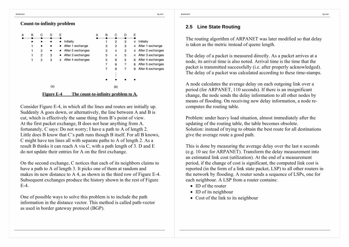
ELEC2402 Pg 201
Count-to-infinity problem
Figure E-4 The count-to-infinity problem to A.
Consider Figure E-4, in which all the lines and routes are initially up.Suddenly A goes down, or alternatively, the line between A and B iscut, which is effectively the same thing from B’s point of view.At the first packet exchange, B does not hear anything from A.fortunately, C says: Do not worry; I have a path to A of length 2.Little does B know that C’s path runs though B itself. For all B knows,C might have ten lines all with separate paths to A of length 2. As aresult B thinks it can reach A via C, with a path length of 3. D and Edo not update their entries for A on the first exchange.
On the second exchange, C notices that each of its neighbors claims tohave a path to A of length 3. It picks one of them at random andmakes its new distance to A 4, as shown in the third row of Figure E-4.Subsequent exchanges produce the history shown in the rest of FigureE-4.
One of possible ways to solve this problem is to include the pathinformation in the distance vector. This method is called path-vectoras used in border gateway protocol (BGP).
ELEC2402 Pg 202
2.5 Line State Routing
The routing algorithm of ARPANET was later modified so that delayis taken as the metric instead of quene length.
The delay of a packet is measured directly. As a packet arrives at anode, its arrival time is also noted. Arrival time is the time that thepacket is transmitted successfully (i.e. after properly acknowledged).The delay of a packet was calculated according to these time-stamps.
A node calculates the average delay on each outgoing link over aperiod (for ARPANET, 110 seconds). If there is an insignificantchange, the node sends the delay information to all other nodes bymeans of flooding. On receiving new delay information, a node re-computes the routing table.
Problem: under heavy load situation, almost immediately after theupdating of the routing table, the table becomes obsolete.Solution: instead of trying to obtain the best route for all destinationsgive the average route a good path.
This is done by measuring the average delay over the last n seconds(e.g. 10 sec for ARPANET). Transform the delay measurement intoan estimated link cost (utilization). At the end of a measurementperiod, if the change of cost is significant, the computed link cost isreported (in the form of a link state packet, LSP) to all other routers inthe network by flooding. A router sends a sequence of LSPs, one foreach neighbour. A LSP from a router contains:
• ID of the router• ID of its neighbour• Cost of the link to its neighbour

ELEC2402 Pg 203
In this way, each router receives not just the cost information but alsothe topological information (since LSP from a router contains the IDof its neightbour). This additional information helps to preventlooping problems (e.g. count-to-infinity), which are due to the lack oftopological information of the network. A router may also requestanother router for its LSP. Each router maintains the received LSPinformation in a LSP database. A router uses this database tocomputer the optimal routes to all destinations according to certainalgorithm. Dijkstra’s shortest-path algorithm (or its variation) iscommonly used.
ELEC2402 Pg 204
3. Congestion control algorithms
A packet network can be modeled as a pool of resources in terms ofchannels, buffers and switches.
Unrestricted or uncontrolled competition for the resources may cause:• Inefficiency Resources are wasted• Unfairness Some users capture large source of resources than
others.• Congestion Part of the network becomes a bottleneck &
throughput drops as a result. Worst case: deadlock.
Figure E-5 When too much traffic is offered, congestion sets in andperformance degrades sharply.
In packet network, flow control procedures are used to solve theseproblems.

ELEC2402 Pg 205
3.1 General Principles of congestion control• Monitor the system to detect when and where congestion occurs.• Pass this information to places where action can be taken• Adjust system operation to correct the problem
3.2 Congestion prevention policiesIn Figure E-6, different data link, network, and transport policies thatcan affect congestion are shown.
Figure E-6 Policies that affect congestion
ELEC2402 Pg 206
3.3 Congestion control in virtual-circuit subnetsOnce the congestion has been signaled, no more virtual circuits are setup until the problem has gone away.
3.4 Congestion control in datagram subnets
Each router can easily monitor the utilization of its output lines andother resources. In case of congestion control, several actions can betaken.
The warning bitSet by router in the packet the congestion warning state. Thedestinations copied the bit into the next acknowledgement sentback to the source. As long as the warning bits continued to flowin, the source continued to decrease its transmission rate.
Choke packetsThe router sends a choke packet back to the source host directlyto request it to slow down the traffic.
Hop-by-Hop chock packetsSame as choke packets, except the effect takes at every hop itpasses through.
3.5 Load SheddingWhen none of the above methods make the congestion disappear,routers can bring out he heavy artillery: load shedding by randomlythrow packets out, except packets marked with “VERYIMPORTANT –NEVER, EVER DISCARD”.

ELEC2402 Pg 207
4. Quality of service
With the growth of multimedia networking, often ad hoc messages arenot enough. Serious attempts at guaranteeing quality service throughnetwork and protocol design are needed.
4.1 RequirementsA stream of packets from a source to a destination is called a flow. Ina connection-oriented network, all the packets belonging to a flowfollow the same route; in a connectionless network, they may followdifferent routes. The needs of each flow can be characterized by fourprimary parameters: reliability, delay, jitter (the variation (i.e.,standard deviation) in the packet arrival times is called jitter), andbandwidth. Together these determine the QoS (Quality of Service) theflow requires. Several common applications and stringency of theirrequirements are listed below.
Figure E-7 How stringent the quality-of-service requirements are.
ELEC2402 Pg 208
ATM networks classify flows in four broad categories with respect totheir QoS demands as follows:Constant bit rate (e.g., telephony).Real-time variable bit rate (e.g., compressed videoconferencing).Non-real-time variable bit rate (e.g., watching a movie over theInternet).Available bit rate (e.g., file transfer).
These categories are also useful for other purposes and other networks.
4.2 Techniques for Achieving Good Quality of Service
OverprovisioningAn easy solution is to provide so much router capacity, buffer space,and bandwidth that the packets just fly through easily.
BufferFlows can be buffered on the receiving side before being delivered.Buffering them does not affect the reliability or bandwidth, andincreases the delay, but it smoothes out the jitter. For audio and videoon demand, jitter is the main problem, so this technique helps a lot.
Figure E-8 Smoothing the output stream by buffering packets.

ELEC2402 Pg 209
Traffic Shaping
Non-uniform output is common if the server is handling many streamsat once, and it also allows other actions, such as fast forward andrewind, user authentication, and o on. Also, the approach we used here(buffering) is not always possible, for example, withvideoconferencing. However, if something could be done to make theserver (and hosts in general) transmit at a uniform rate, quality ofservice would be better.
Traffic shaping = smooths out the traffic on the server side, rather thanon the client side.
Traffic shaping is about regulating the average rate (and burstiness) ofdata transmission. In contrast, the sliding window protocols limit theamount of data in transit at once, not the rate at which it is sent. Whena connection is set up, the user and the subnet agree on a certain trafficpattern for that circuit. Sometimes this is called a service levelagreement. As long as the customer fulfills her part of the bargain andonly sends packets according to the agreed-on contract, the carrierpromises to deliver them all in a timely fashion.
ELEC2402 Pg 210
The Leaky bucket Algorithm
Imagine a bucket with a small hole in the bottom, as illustrated inFigure E-9(a). No matter the rate at which water enters the bucket, theoutflow is at a constant rate, when there is any water in the bucket andzero when the bucket is empty. Also, once the bucket is full, anyadditional water entering it spills over the sides and is lost.
The same idea can be applied to packets, as shown in Figure E-9(b).Conceptually, each host is connected to the network by an interfacecontaining a leaky bucket, that is a finite internal queue. If a packetarrives at the queue when it is full, the packet is discarded. In otherwords, if one or more processes within the host try to send a packetwhen the maximum number is already queued, the new packet isunceremoniously discarded.
Figure E-9 (a) A leaky bucket with water. (b) A leaky bucket withpackets.

ELEC2402 Pg 211
The Token Bucket Algorithm
The leaky bucket algorithm enforces a rigid output pattern at theaverage rate, no matter how bursty the traffic is. For manyapplications, it is better to allow the output to speed up somewhatwhen large bursts arrive, so a more flexible algorithm is needed,preferably one that never loses data. => Token Bucket Algorithm.
In this algorithm, the leaky bucket holds tokens, generated by a clockat the rate of one token every T sec. In Figure E-10(a), a bucketholding three tokens, with five packets waiting to be transmitted. For apacket to be transmitted, it must capture and destroy one token. InFigure E-10(b) three of five packets have gotten through, but the othertwo are stuck waiting for two more tokens to be generated.
Figure E-10 The token bucket algorithm. (a) Before. (b) After.
ELEC2402 Pg 212
Resource ReservationBeing able to regulate the shape of the offered traffic is a good start toguaranteeing the quality of service. However, effectively using thisinformation implicitly means requiring all the packets of a flow tofollow the same route. Spraying them over routers at random makes ithard to guarantee anything. As a consequence, something similar to avirtual circuit has to be set up from the source to the destination, andall the packets that belong to the flow must follow this route.
Admission ControlBecause many parties may be involved in the flow negotiation (thesender, the receiver, and all the routers along the path between them),flows must be described accurately in terms of specific parametersthat can be negotiated. A set of such parameters is called a flowspecification. Typically, the sender (e.g., the video server) produces aflow specification proposing the parameters it would like to use. Asthe specification propagates along the route, each router examines itand modifies the parameters as need be. The modifications can onlyreduce the flow, not increase it (e.g., a lower data rate, not a higherone). When it gets to the other end, the parameters can be established.
Proportional RoutingMost routing algorithm try to find the best path for each destinationand send all traffic to that destination over the best path. A differentapproach that has been proposed to provide a higher quality of serviceis to split the traffic for each destination over multiple paths. Sincerouters generally do not have a complete overview of network-widetraffic, the only feasible way to split traffic over multiple routes is touse locally available information. A simple method is to divide thetraffic equally or in proportion to the capacity of the outgoing links.However, more sophisticated algorithms are also available.

ELEC2402 Pg 213
Packet Scheduling
Fair queuing algorithmRouter have separate queues for each output line, one for eachflow. When a line becomes idle, the router scans the queuesround robin, taking the first packet on the next queue. In this way,with n hosts competing for a given output line, each host gets tosend one out of every n packets. Sending more packets will notimprove this fraction.
Problem: It gives more bandwidth to hosts that use large packetsthan to hosts that use small packets. An improvement in whichthe round robin is done in such a way as to simulate a byte-by-byte round robin, instead of a packet-by-packet round robin. Ineffect, it scans the queues repeatedly, byte-to-byte, until it findsthe tick on which each packet will be finished. The packets arethen sorted in order of their finishing and sent in that order. Thealgorithm is illustrated in Figure E-11.
Figure E-11 (a) A router with five packets queued for line O. (b)Finishing times for the five packets.
ELEC2402 Pg 214
4.3 Integrated Services
Between 1995 and 1997, IETF (Internet Engineering Task Force)devising an architecture for streaming multimedia. This work resultedin over two dozen RFCs, starting with RFCs 2205-2210. The genericname for this work is flow-based algorithms or integrated services.
RSVP – The Resource reservation Protocol
The main IETF protocol for the integrated services architecture isRSVP. It is described in RFC 2205 and others. This protocol is usedfor making the reservations; other protocols are used for sending thedata. RSVP allows multiple senders to transmit to multiple groups ofreceivers, permits individual receivers to switch channels freely, andoptimizes bandwidth use while at the same time eliminatingcongestion.
In its simplest form, the protocol use multicast routing using spanningtrees. Each group is assigned a group address. To send to a group, asender puts the group’s address in its packets. The standard multicastrouting algorithm then builds a spanning tree covering all groupmembers. The routing algorithm is not part of RSVP. The onlydifference from normal multicasting is a little extra information that ismulticast to the group periodically to tell the routers along the tree tomaintain certain data structures in their memories.
As an example, consider the network of Figure E-12. Hosts 1 and 2are multicast senders, and hosts 3, 4, and 5 are multicast receivers. Inthis example, the senders and receivers are disjoint, but in general, thetwo sets may overlap. The multicast trees for hosts 1 and 2 are shownin Figure E-12(b) and Figure E-12(c), respectively.

ELEC2402 Pg 215
Figure E-12 (a) A network. (b) The multicast spanning tree for host 1.(c) The multicast spanning tree for host 2
Every client can send a reservation message (flow descriptor) to itsupstream router, specifying the desired QOS (Quality of services) andthe set of packets to receive in a session. On receiving a reservationmessage, a router allocates its resources and adjusts its packetscheduler to meet the request. It then in turn sends a reservationmessage to the next upstream router. Reservations received by a routerare merged. An example of such a reservation is shown in Figure E-13below.
Figure E-13 (a) Host 3 requests a channel to host 1. (b) Host 3 thenrequests a second channel, to host 2. (c) Host 5 requests a channel to host1.
ELEC2402 Pg 216
4.4 Differentiated Services
Flow-based algorithms have the potential to offer good quality ofservice to one or more flows because they reserve whatever resourcesare needed along the route. However, they also have a downside.They require an advance setup to establish each flow, something thatdoes not scale well when there are thousands or millions of flows.Also, they maintain internal per-flow state in the routers, making themvulnerable to router crashes. Finally, the changes required to the routercode are substantial and involve complex router-to-router exchangesfor setting up the flows. As a consequence, few implementations ofRSVP or anything like it exist yet.
For these reasons, IETF has also devised a simpler approach to qualityof service, one that can be largely implemented locally in each routerwithout advance setup and without having the whole path involved.This approach is known as class-based (as opposed to flow-based)quality of service. IETF has standardized an architecture for it, calleddifferentiated services.
Differentiated services (DS) can be offered by a set of routers formingan administrative domain (e.g., an ISP or a telco). The administrationdefines a set of service classes with corresponding forwarding rules. Ifa customer signs up for DS, customer packets entering the domainmay carry a type of service field in them, with better service providedto some classes (e.g., premium service) than to others. Traffic within aclass may be required to conform to some specific shape, such as aleaky bucket with some specified drain rate. An operator with a nosefor business might charge extra for each premium packet transportedor might allow up to N premium packets per month for a fixedadditional monthly fee. Note that this scheme requires no advancesetup, no resource reservation, and no time-consuming end-to-endnegotiation for each flow, as with integrated services. This makes DSrelatively easy to implement.

ELEC2402 Pg 217
Expedited Forwarding
The choice of service classes is up to each operator, but since packetsare often forwarded between subnets run by different operators, IETFis working on defining network-independent service classes. Thesimplest class is expedited forwarding and is described in RFC 3246.
The idea behind expedited forwarding is very simple. Two classes ofservice available: regular and expedited. The vast majority of thetraffic is expected to be regular, but a small fraction of the packets areexpedited. The expedited packets should be able to transit the subnetas though no other packets were present.. a symbolic representation ofthis “two-tube” system is given in Figure E-14. Note that there is stilljust one physical line. The two logical pipes shown in the figurerepresent a way to reserve bandwidth, not a second physical line.
One way to implement this strategy is to program the routers to havetwo output queues for each outgoing line, one for expedited packetsand one for regular packets.
Figure E-14 Expedited packets experience a traffic-free network.
ELEC2402 Pg 218
Assured Forwarding
Described in RFC 2597. It specifies that there shall be four priorityclasses, each class having its own resources. In addition, it definesthree discard probabilities for packets that are undergoing congestion:low, medium, and high. Taken together, these two factors define 12service classes.
Figure E-15 shows one way packets might be processed under assuredforwarding. Step 1 is to classify the packets into one of the fourpriority classes. This step might be done on the sending host (asshown in the figure) or in the ingress (first) router. The advantage ofdoing classification on the sending host is that more information isavailable about which packets belong to which flows there.
Figure E-15 A possible implementation of the data flow for assuredforwarding.

ELEC2402 Pg 219
Step 2 is to mark the packets according to their class. A header field isneeded for this purpose. Fortunately, an 8-bit Type of service field isavailable in the IP header, as we will see shortly. RFC 2597 specifiesthat six of these bits are to be used for the service class, leavingcoding room for historical service classes and future ones.
Step 3 is to pass the packets through a shaper/dropper filter that maydelay or drop some of them to shape the four streams into acceptableforms, for example, by using leaky or token buckets. If there are toomany packets, some of them may be discarded here, by discardcategory. More elaborate schemes involving metering or feedback arealso possible.
In this example, these three steps are performed on the sending host,so the output stream is now fed into the ingress router. It is worthnoting that these steps may be performed by special networkingsoftware or even the operating system to avoid having to changeexisting applications.
ELEC2402 Pg 220
4.5 Label Switching and MPLS
While IETF was working out integrated services and differentiatedservices, several router vendors were working on better forwardingmethods. This work focused on adding a label in front of each packetand doing the routing based on the label rather than on the destinationaddress. Making the label an index into an internal table makesfinding the correct output line becomes just a matter of table lookup.Using this technique, routing can be done very quickly and anynecessary resources can be reserved along the path.
This “new” switching idea goes by various (proprietary) names,including label switching and tag switching. Eventually, IETF beganto standardize the idea under the name MPLS (Multi-Protocol LabelSwitching) and is described in RFC 3031 and many other RFCs.
A new MPLS header is added in front of the IP header. On a router-to-router line using PPP as the framing protocol, the frame format,including the PPP, MPLS, IP, and TCP headers, is as shown in FigureE-16.
Figure E-16 Transmitting a TCP segment using IP, MPLS, and PPP.

ELEC2402 Pg 221
5. Internetworking
Until now, we have implicitly assumed that there is a singlehomogeneous network, with each machine using the same protocol ineach layer. Unfortunately, this assumption is wildly optimistic.
Many different networks exist, including LANs, MANs and WANs.
Numerous protocols are in widespread use in every layer. Even withinan organization, different networks are used at the dame time fordifferent purposes using different technologies. In fact, networks havebeen introduced over time and may not want to replace them all at thesame time.
In the following sub-sections we will take a careful look at the issuesthat arise when two or more networks are connected to form anInternet.
ELEC2402 Pg 222
5.1 Requirement for internetworking
i. Physical connection between networks, which may usedifferent physical media.
ii. Data link connection between networks.iii. Data routing between end-stations in different networksiv. Provide account service.v. Provide protocol conversion in such a way that here should
be no modifications required to the networks connected.Common protocol differences are:• Different address scheme• Different maximum packet size• Different network access• Different timeouts• Error recovery• Different status and performance reports• Different routing algorithms• Different user access control• Connection and connectionless services

ELEC2402 Pg 223
5.2 Network connection
(i) Hardware
(a) RepeatersA repeater is used to connect two network segments. It repeatsthe information received from one segment by amplifying thesignal received from that segment and then transmitting theamplified signal to the other segment. It functions at the physicallayer.
(b) BridgesA bridge is used to link two network segments, which may ormay not be of the same media types. It differs from a repeater inthat a bridge makes decision on the handling of a frame received.A bridge offers filtering and relaying (forwarding) services.Therefore, a bridge can be used to isolate two network segments.If the network segments are of different types, frame translationis required. A bridge has a protocol stack covering the physicallayer and the data link layer (MAC and LLC sub-layers).Therefore, a bridge is also called a layer device.
ELEC2402 Pg 224
(c) RoutersAn Internet contains heterogeneous networks which areconnected by special devices called router.
A router has a protocol stack, which covers the physical layer,the data link layer and the network layer. It passes (routes)packets from one network to another network so that the packetwill eventually arrives at its destination.
Figure E-17 A collection of interconnected networks.(SNA = System Network Architecture Protocol developed in
1970s by IBM,FDDI = Fiber Distributed Data Interface - ISO 9314)
As the size of Internet grows, the task of routing becomes morecomplex. Therefore, route a packet based on the destinationnetwork rather than individual station /end system (commonlycalled host).

ELEC2402 Pg 225
(ii) Protocols used for internetworking
The protocol stack commonly used in an Internet (global/private)is called TCP/IP (Transmission Control Protocol / InternetProtocol).
This protocol stack is designed to provide universal servicesamong stations independent of the network to which they areattached. Therefore, TCP/IP presents the Internet to the users as avirtual network.
Figure E-18 The Internet is an interconnected collection of manynetworks.
ELEC2402 Pg 226
Universal services:• Unique address for each host• Network equality• Host can send a packet to any other host
The protocol hides the details of physical connections, physicaladdresses and routing information from the users. It offers theusers the facilities of a large virtual network.

ELEC2402 Pg 227
Section F
Introduction to TCP (Layer 4)/ IP(Layer 3)
1. Basic operations of TCP/IP:
2. Resolution of IP address
3. IP Datagram
4. Routing of IP Datagrams/Fragments
5. Internet Control Message Protocol (ICMP)
6. Internet Multicasting
7. Transport Protocol: TCP
8. UDP Connectionless Services
ELEC2402 Pg 228
Introduction
TCP/IP can be characterized as a layered architecture as shown below.
Figure F-1 The TCP/IP reference model
TCP/IP has a protocol stack of four layers. Most of the layerscorrespond to the OSI layers. However, OSI does not have a layercorresponding to the TCP/IP Internet layer. The OSI layer closest tothe Internet layer is the Network layer.

ELEC2402 Pg 229
Layer 1: Host-networkBelow the internet layer is great void. The TCP/IP referencemodel does not say much here, except to point out that this hosthas to connect to he network using some protocol so it can sendIP packets to it and this protocol is not defined and varies fromhost to host and network to network.
Layer 2: InternetSpecify how data are put into packets and how to route a packetfrom the source host to the destination host through one or morerouters. The protocol used in this layer is called IP (InternetProtocol).
(The major difference between Internet layer and the OSInetwork layer is that he Internet layer provides a seamless virtualnetwork made up of heterogeneous networks.)
Layer 3: TransportSpecify how end-to-end data can be transferred reliably throughthe Internet. The protocol used in this layer is called TCP(Transmission Control Protocol) and UDP (User DatagramProtocol)
Layer 4: ApplicationThe layer-4 protocol specifies how an application performs dataexchange through the Internet.For example:• Telnet (virtual terminal)• FTP (File Transfer Protocol)• SMTP (simple Mail Transfer Protocol)• DNS (Domain Name Service)• HTTP (Hyper Text transfer Protocol)
ELEC2402 Pg 230
In TCP/IP the use of all layers is not mandatory.e.g. some applications use IP directly.
TCP/IP supports universal services by providing global addressing.Each host has one or more unique global addresses. Two Internethosts can identify each other by means of their global addresses.
Figure F-2 Internet Protocol Operation

ELEC2402 Pg 231
1. Basic operations of TCP/IP:
The concept of TCP/IP operations are illustrated in Figure F-2.
• Each application process (AP) in a host transmits to or receivesdata from the TCP layer via one or more ports (known asservice access point (SAP) in OSI).
The connection between the corresponding ports at the endsystems is called a TCP connection. This connection can beidentified by the corresponding port address in each host. Theidentity of a port in a host is unique in that host so that a hostcan identify a particular AP.
However, unlike a host address, a port identity is not a globaladdress. It is used to identify the communicating APs in thehosts concerned.
• TCP ensures reliable data transmission in a TCP connectionbetween the corresponding APs.(Note: TCP offers both connection and connectionless
services.)
• TCP is implemented only at the hosts (end systems).
• A TCP connection makes use of IP to exchange data with theother host through the Internet.(Note that IP does not need to know the identity of thedestination port. Its job is to route data to the destination host.The TCP in that host will use the information attached to thedata to find out the port number and send it to the appropriateapplication process.)
ELEC2402 Pg 232
• Each host can be identified by its unique global address. Thisallows ip to route data from the TCP layer to the destinationhost. If the communicating hosts are on different networks, thepath goes through one or more routers.
• IP is implemented in all the hosts as well as the routers.• IP exchanges data with the network, to which the host is
attached, via the network interface and the physical layers. E.g.IEEE 802.3 CSMA/CD,FDDI.
Therefore, two levels of addressing: IP address and port.
Figure F-3 Protocol Data Units in the TCP/IP Architeture.Data units from a layer may be fragmented when passed down to alower layer and reassembled when passed up to a higher layer.

ELEC2402 Pg 233
1.1 Internet Protocol: IP
IP Addressing Scheme
The major difference between Internet and a physical network is thatInternet is an abstraction presented by software (with the help ofrouters). The users view the Internet as a large seamless virtualnetwork connecting many hosts. In order to route data to a host, eachhost in the Internet is assigned one or more unique global addresses,the IP addresses. The IP addressing scheme must be independent ofthe underneath physical networks so that the APs can communicatewithout knowing the physical address of the other party.
Classes of IP AddressesAn Internet address has 32 bits which is divided into 2 hierarchicalparts:
• PrefixIdentifies a network number i.e. the identity of the physicalnetwork to which the host is attached. A network number is aunique number in Internet and is assigned globally by theInternet Assigned Number Authority.
• SuffixIdentifies a host on the attached network. This portion of thehost address must be unique within the boundary of theattached network, i.e. not assigned globally
Therefore, each IP address is unique in the Internet.
ELEC2402 Pg 234
Hosts in the same physical network have the same prefix.Hosts in different physical networks have different prefixed but mayhave the same suffix
Question:How many bits in each address field?Problem: Need to accommodate all sorts of network. Some are large
(therefore, need a longer suffix fields) and some are small(therefore, need a shorter suffix field).
Solution: Have different classes of IP addresses. Each class has adifferent for suffix and prefix.
There are five classes of IP address as shown below:
Figure F-4 IP address format
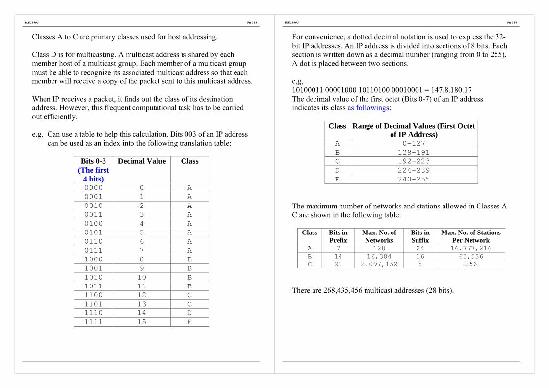
ELEC2402 Pg 235
Classes A to C are primary classes used for host addressing.
Class D is for multicasting. A multicast address is shared by eachmember host of a multicast group. Each member of a multicast groupmust be able to recognize its associated multicast address so that eachmember will receive a copy of the packet sent to this multicast address.
When IP receives a packet, it finds out the class of its destinationaddress. However, this frequent computational task has to be carriedout efficiently.
e.g. Can use a table to help this calculation. Bits 003 of an IP addresscan be used as an index into the following translation table:
Bits 0-3(The first
4 bits)
Decimal Value Class
0000 0 A0001 1 A0010 2 A0011 3 A0100 4 A0101 5 A0110 6 A0111 7 A1000 8 B1001 9 B1010 10 B1011 11 B1100 12 C1101 13 C1110 14 D1111 15 E
ELEC2402 Pg 236
For convenience, a dotted decimal notation is used to express the 32-bit IP addresses. An IP address is divided into sections of 8 bits. Eachsection is written down as a decimal number (ranging from 0 to 255).A dot is placed between two sections.
e,g,10100011 00001000 10110100 00010001 = 147.8.180.17The decimal value of the first octet (Bits 0-7) of an IP addressindicates its class as followings:
Class Range of Decimal Values (First Octetof IP Address)
A 0-127B 128-191C 192-223D 224-239E 240-255
The maximum number of networks and stations allowed in Classes A-C are shown in the following table:
Class Bits inPrefix
Max. No. ofNetworks
Bits inSuffix
Max. No. of StationsPer Network
A 7 128 24 16,777,216B 14 16,384 16 65,536C 21 2,097,152 8 256
There are 268,435,456 multicast addresses (28 bits).

ELEC2402 Pg 237
1.2 Special IP Addresses
There are some IP addresses reserved for special purposes as shownbelows. These addresses are not assigned to hosts.
Figure F-5 Special IP addresses.
1.3 Multi-homed hostsIt is easier to view that an IP address is assigned to a host, this idea isnot accurate. Consider the following situations in which a host isconnected to multiple networks:
• A host can be connected to more than one network forreliability or for performance. This kind o hosts is called multi-homed hosts. In order to send packets to this host alongdifferent network connections, each of its network connectionmust have a unique IP address; therefore a multi-homed hosthas multiple IP addresses.
ELEC2402 Pg 238
• In Internet, a router is also assigned with IP address. Since arouter has multiple network connections, it has multiple IPaddresses, one for each network connection.
For a host with only a single network connection, it does not matter totreat the IP address as the address of the host or the address of itsnetwork connection.
Figure F-6 Three interconnected networks: Ethernets and FDDI ring (The IPaddress are examples only and have no special meaning).
In the above diagram, each connection of a router has an IP address.The host shown in Network 3 is connected to Network 3 (an Ethernet)and Network 2 (a FDDI). Therefore there are two IP addresses for thishost, one for each connection.

ELEC2402 Pg 239
1.4 Problems with the IP Addressing Scheme
• When a host moves to another network, need to change the IPaddress. Prefix -> network number.
• When a class C network grows beyond 255 hosts, it has tochange to Class B or Class A. this implies that all the IPaddresses of the network and all its hosts must change.
• Internet routes a packet according to the IP address of itsdestination. Therefore, the route taken by packets destined to amulti-homed host depends on which IP address is used. Whichaddress should be used?
• Because of network faults, a multi-homed host may not bereached by one of its IP address but may still be reached by itsother IP addresses. Need to know all its IP addresses.
ELEC2402 Pg 240
2. Resolution of IP address
An IP address is a virtual (logical) element. It exists only in the IPsoftware. The hardware of the Internet components (networks andhosts) are not understand the IP address but only the physical(hardware) addresses. When routing a packet to a host, must know thephysical address of the next hop. Therefore, the IP protocol needs tomap (bind) an IP address to a physical address. This translation,known as address resolution, is hidden from the users.
However addresses must be resolved locally.
e.g.
Figure F-7 Two subnet connected by routers.
As shown in the diagram above, Host H1 sends data to Host H2 usingthe IP address. H1 and H2 are local stations on the same network(Network 1). The IP protocol software in H1 resolves the IP address tothe physical address of H2 and sends data to H2 using this physicaladdress.

ELEC2402 Pg 241
H1 sends data to H3 which is on a different network Network 2 (i.e.H1 and H3 are not local stations on the same network). The protocolsoftware in H1 does not resolve the IP address of H3. It knows thatdata has to be routed through the router R1, which is local on Network1. It resolves the IP address of R1 and sends data using the physicaladdress of R1. When R1 receives the data, it knows that the data hasto be routed to H3, which is local with it on Network 2. It resolves theIP address of H3 and forward the data to it accordingly.
The following are three basic address resolution methods:(i) Table Lookup
The binding information are stored in a table.Suitable for resolving IP Addresses across WAN.
(ii) Closed-form computationAssign an IP address in such a way that there is a one-to-onemathematical function between the physical address and the IPaddress.Suitable for configurable network.
(iii) Message exchangeMessages are exchanged among hosts/routers to achieve addressbinding. Suitable for LAN with static addresses.
Need a protocol for mapping IP onto data link layer addresses, such asEthernet. Can have special server to handle the protocol of addressresolution. TCP/IP defines a protocol for this purpose: AddressResolution Protocol (ARP).
ELEC2402 Pg 242
2.1 Address Resolution Protocol (ARP – RFC826)
Problem:How do IP addresses get mapped onto datalink layer addresses,such as Ethernet?
Solution:ARP request message is broadcast throughout the network. Thetargeted host sends a response on receiving the request.
ARP solves the problem of finding out which Ethernet addresscorresponds to a given IP address. The protocol is shown below:
Figure F-8 The Address Resolution Protocol.

ELEC2402 Pg 243
Figure F-9 Operation of ARP request and response.In the above example, the Request message from Host A contains itsown hardware and protocol addresses and also the hardware orprotocol address of the targeted host (Host B). Host B on receivingthis message finds that the Request is targeted on it. It then sends backa Response message directly (not by broadcast) to Host A containedits hardware and protocol addresses.
The hardware type field in a message indicates the hardware interfacetype. e.g. 1 for Ethernet.
The protocol type field indicates the protocol type used.e.g. 0800(Hex.) for IP.(Note that ARP is designed to use in any network protocol, whichrequires address resolution, not just TCP/IP. Therefore, need toindicate the protocol type.)
In order to make ARP general and not to exclude future networktechnologies, length fields are used to indicate the length of thehardware and protocol addresses. At present the most commonly usedaddresses are:
Ethernet address: 48 bitsIP address: 32 bits
ELEC2402 Pg 244
2.2 Sending ARP messagesUse network interface to send ARP message, e.g. if the network is anEthernet. Encapsulate the ARP message in an Ethernet frame asshown below:
ARP Message
Header Data FCSFigure F-10 ARP Message Encapsulation.
Can indicate that this is a ARP message in the length/type field of anEthernet header.
2.3 Address Binding CacheBroadcasting of ARP Requests creates a lot of traffic. Therefore, savethe binding information for future use. However, may have muchbinding information. Therefore, use a cache to hold the most recentlyreceived bindings.
On receiving a ARP message, a host:(i) Checks whether the sender’s binding in the message is
already in the cache.It yes, checks whether the binding is the same as that in thecache. If no, updates the cache.
(ii) Checks whether the message is a request or response.If it is a request and the host is a target, sends a ARPresponse to the sender.

ELEC2402 Pg 245
3. IP Datagram
TCP/IP includes protocols for both connection and connectionless-oriented services. However, the basic delivery service of TCP/IP isconnectionless at the Internet Layer. Therefore, a packet in IP is calleda IP datagram.
The format of IP datagram is shown as following:
Figure F-11 The IPv4 (Internet Protocol) header.
Version: Version number of the IP protocolHeader Length(IHL):
Length of the Header in multiple of 32 bits (4 octets).Minimum value is 5, i.e. 20 octets.
Type ofServices:
Specifies service preference of minimal delay or maximumthroughput.
Total length: Total length of datagram (in octets).Identification: A sequence number of the data gram. Together with the
source, destination addresses and user protocol, this numbercan uniquely identify a datagram.
Flags: (DF,MF) Contains two defined bits.“More” bit is used for the fragmentation and reassembly ofa datagram. It indicates whether the fragment is the last oneof a datagram.
ELEC2402 Pg 246
“Don’t Fragment” bit prohibits fragmentation. In this case,may use source routing to avoid network routes withmaximum packet size smaller than required. All machinesare required to accept fragments of 576 bytes or less.
FragmentOffset:
Indicates the position of this fragment in the originaldatagram. This is measured in 64-bit units (i.e. 8 octets).Therefore, fragments other than the last fragment must havea data field whose length is a multiple of 64 bits.
Time-to-live(TTL):
Specifies the lifetime of a datagram in the Internet. TTL canbe taken as a hop count. When a datagram arrives at arouter, the router decrements the TTL by >=1. When TTLbecomes zero before reaching the destination, the datagramis discarded and the source will be informed by the routeraccordingly.
Protocol type: Specifies the type of data, i.e. the higher level protocol toreceive the datagram.
Headerchecksum:
The header (excluding the checksum field itself) is treatedas a sequence of 16 bit integers. These integers are added in1’s compliment arithmetic. The 1’s compliment of this sumis taken as the checksum.
Source IPaddress:
IP address of the sender.
Destination IPaddress:
IP address of the destination.
Options &Padding:
These two fields may be absent. In this case, the headerlength field=5.The option field, if present, is used to indicate whether thedatagram is for testing/debugging and control purposes. Theoption field has a variable length depending on the optionsspecified. If the option field is not 2bits long, a paddingfield is used to run the header into a multiple of 32 bits.
Data: The length of this field varies. It must be a multiple of octetin length. The maximum length of a IP datagram is 65,535octets.

ELEC2402 Pg 247
3.1 IP Datagram Encapsulation
The datagram format is not known to the physical networks. Need toencapsulate the datagram into a frame of the physical network.
IPHeader
IP Data Area
: :FrameHeader
Frame Data
Figure F-12 IP Datagram Encapsulation.
Depends on the physical network, there may be a trailer (e.g. FCS inthe Ethernet format).
The physical network needs to know:(i) The physical address of the next hop;
Bind the IP address to a physical address as describe before.
(ii) The type of frame so that the receiver of the frame knowsthat this is an encapsulated IP datagram.There is a field in the header of a physical network frame toindicate the type of frame. IP marks this type field toindicate that there is an IP datagram of the frame.
This encapsulation process has to be carried out per hop as shown inFigure F-13.
ELEC2402 Pg 248
Figure F-13 IP Datagram encapsulation process.
3.2 Fragmentation of IP DatagramsIn general, there is a maximum size of data that a physical networkcan carry in a frame
Maximum transmission unit (MTU)
A IP datagram may not fit into a frame. Fragmentation at one end and reassembly at the other
end.

ELEC2402 Pg 249
Each fragment has the same format as a IP datagram and isencapsulated in a frame of the physical network. The header of afragment is a modified version of the header in the original datagramas shown in the diagram below:
Figure F-14 Fragmentation of IP Datagrams
The Fragment Offset field in the header of a fragment indicates itsposition in the data area of the original datagram. This information canbe used when reassembling fragments back to the original datagram.
It is possible that fragments from different datagrams of the samesource are received. Can use the information contained in theIdentification and the Source IP Address fields in the header tosegregate the fragments.
Question:Where should the fragments of an IP datagram be assembled?
IP specifies that the destination host should do the reassembly.• If reassembly takes places at each router, it is too time consuming.• If it is the router does the assembly task, every fragment of the
same datagram must be routed to this router.
ELEC2402 Pg 250
It is also possible to have fragmentation of a datagram fragment. Thishappens when a fragment arrives at a network with smaller MTU.
Fragments may be lost -> cannot complete reassembly task.
Use a time-out process. On the first arrival of a datagram fragment,start the timer. If, all the fragments of that datagram have not arrivedwhen the timer expires, discard all the received fragments of thatdatagram.
4. Routing of IP Datagrams/FragmentsIP datagrams are routed from the source host to the destination host
through a number of routers (as shownin the diagram on the left side). Eachrouter on receiving a datagram,examines its destination IP address. Itthen consults a routing table todetermine which is the next hop forthat datagram. The following is anexample of a routing table at Router R1:
Destination Mask Next Hop120.0.0.0 255.0.0.0 Local147.8.0.0 255.255.0.0 Local200.1.8.0 255.255.255.0 120.3.18.36

ELEC2402 Pg 251
The router obtains the destination address, D from the header. It usesthe mask field in the table entry to extract the prefix (network part) ofthe address and then compare the masking result with the destinationfield. If matched, routes according to the corresponding next hop field.
If ((Mask[I] & D) = Destination[i])then forward (NextHop[I])else next_entry;
Obviously the mask for Class A is 255.0.0.0; that of Class b is255.255.0.0 and that for Class C is 255.255.255.0.
Datagrams are routed on a “best-effort” basis. There is no guaranteethat datagrams will not be duplicated, corrupted, lost or delivered out-of-order.
ELEC2402 Pg 252
IPv6IPv4 as described above has certain limitations.
• The size of an IP addresses is limited to 32 bits, although it soundlarge. However this address has to be shared between networkand host identities. New applications use TCP.IP and need toassign IP addresses. E.g. cable TC receivers, point-of-saleterminals,…)
• IPv4 does not support new applications requiring real-timedelivery of audio and video information.
IP-The Next Generation IPng was introduced as IPv6 to overcomethese problems.

ELEC2402 Pg 253
Enhancement of IPv6• Use 128-bit IP addresses ->296 unique addresses.
Should be sufficient for a long, long time.• Option headers are put after the 40-octet mandatory header. Most
routers would not process these option headers.• Dynamic assignment of IPv6 addresses.• Addressing scheme support s anycast (i.e. to just one node in a
set of nodes) and multicast enhancement.• Can label a datagram belonging to certain traffic flow.
Figure F-15 The IPv6 fixed header (required).
Figure F-16 IPv6 mandatory header.
ELEC2402 Pg 254
A IPv6 contains a mandatory header as in Figure F-15 (known as IPv6Base Header), one or more Extension Headers as in Figure F-16 (forspecifying options) and the data area.
The description of the fields of mandatory header are listed as follows:
Version: Version number of the IP protocol (6).Traffic Class: Priority classes.Flow label: For those datagrams requiring special
handling within a network. (e.g. real-timeaudio or video)
Payload length: Length of the datagram excluding themandatory header.
Next Header: Identifies the type of extension header afterthe IPv6 header.
Hop Limit: A simplified TTL. Instead of counting thetime, specifies the number of hops that thedatagram can travel.
Source IPAddress:
IP address of the sender.
Destination IPAddress:
IP address of the destination.

ELEC2402 Pg 255
Unlike IPv4, IPv6 does not have fragmentation information in theheader. This is put into an extension header (Fragment header). Theconcept of the fragmentation process is shown as followings:
Figure F-17 The IPv6 Fragmentation
In IPv6, it is the source host, which is responsible for fragmentation,not the routers. This will reduce the workload on the routers, whichbecome critical when Internet grows larger and larger.
A host sends datagram of various sizes to discover the minimum MTUalong the path (i.e. the path MTU). This discovery is an iterativelearning process.
On top of unicast and multicast, IPv6 has an addition address type.• Anycast (cluster): The address is a set of hosts in the same
network (i.e. sharing a common prefix). The datagram will besent to the host, which is nearest to the sender.
ELEC2402 Pg 256
IPv6 uses IP addresses of 128 bits long. Even the dotted decimal formis difficult to read at this length. Use colon hexadecimal notation,known as colon hex.
An IPv6 address is divided into groups of 16 bits. Each group iswritten in hexadecimal form.
e.g. 68AE:281B:1F:0:0:7086:0:1234
Can use zero compression by throwing away a group with 0 as itsvalue. The above example becomes:
68AE:281B:1F:::7086::1234
0 compression is useful:• To make IPv6 addressing compatible with IPv4, any address
starts with 96 bits of 0 will be taken as a IPv4 address. With 0compression, it is easier to express IPv4 address.
• It is expected that many addresses contain many 0s when start todeploy IPv6.

ELEC2402 Pg 257
5. Internet Control Message Protocol (ICMP)
Although IP offers a connectionless service on a “best effect” basis, arouter reports to the source host the network error conditions that adatagram has encountered. The reporting protocol used in TCP/IP isInternet Control Message Protocol (ICMP) and the network conditionsto be reported are:
(i) Source quenchWhen a router runs out of buffers, it starts to discard incoming IPdatagrams. On discarding a datagram, the router sends a ICMPsource quench message to the source host. On receiving thismessage, a source host reduces the rate of issuing datagrams.(Flow control).
(ii) Time exceededThere are two timing operations:
• TTL timeout• Reassembly timeout
A ICMP time exceed message is sent to the source host reportingone of these situations.
(iii) Destination unreachableWhen a router discovers that a datagram cannot be delivered toits final destination, it sends a ICMP destination unreachablemessage to the source host to indicate whether unreachability isdue to the destined network or due to the destined host.
ELEC2402 Pg 258
(iv) RedirectWhen a router receives a datagram from a host, it checks whetherit is the appropriate router for the datagram. If not, it sends aICMP redirect message to the host indicating a change of thedestined host or a change of the destined network. The host thenadjusts the route accordingly.
(v) Fragmentation requiredWhen a router finds that fragmentation is required but the Don’tFragment” bit in the IP header is set, it discards the datagram andsends a ICMP fragmentation required message to the source host.
ICMP also specifies the following information messages:(vi) Echo Request/Reply
A host sends a ICMP echo request message. The destined hostreturns ICMP echo reply message.
(vii) Address Mask Request/ReplyA host broadcasts a ICMP Address Mask Request messageduring boot-up phase. A router receiving this message returns areply containing the 32 bits subnet mask for the network attachedto it.
(viii)Time stamp request/replySame as echo request/reply, but with timestamp.

ELEC2402 Pg 259
Although functionally ICMP is in the Internet layer, a ICMP messageis encapsulated in a IP datagram (i.e. a user of IP) as shown below:
ICMPHeader
ICMPMessage
: :IPHeader
IPDatagram
: :FrameHeader
NetworkFrame
Figure F-18 ICMP Message Encapsulation.
When a IP datagram carrying a ICMP message causes an error, it willnot be reported.
ICMP is used by some tools for various purposes. e.g.
• Ping (Packet InteNet Groper)This program sends a ICMP echo request message to a destinedhost to test its reachability.
• TracerouteThis program sends a series of probing datagrams to a destinedhost. The first datagram has its TTL set to 1. The first routerhaving decremented TTL to 0, sends a ICMP time exceededmessage to the source host. Therefore, can discover the identityof the first router. By sending out datagrams with a progressivevalues of TTL, the source host may discover the route to thedestination.Potential problems with this program are:
• Datagram loss and duplicated responses;• Dynamic routing of datagrams.
ELEC2402 Pg 260
Can also use ICMP to find the network MTU. Send a probingdatagram with “Don’t Fragment” bit set. If the datagram is too largerfor a router along the path, that router sends the “ICMP fragmentationrequired” message to the source host. The host then sends a datagramwith a shorter length. In this way, a host can discover the networkMTU. This method has the same problems as traceroute. Thereforethese applications are suitable for stable routes.
6. Internet MulticastingMulticast allows a host to send a datagram to more than one host.Unlike broadcasting, a host can decide whether to take part in amulticast.
Simplest way: Use unicast network to emulate multicast network.Sender sends a separate copy to each recipient. -> Inefficient.
Provide explicit support of multicasting at the network level. Thesender sends only a copy of datagram, which is replicated at a networkrouter (with multicast capability), which has multiple outgoing links toreach the recipients.
Multicast hardware reserves a large set of addresses for multicast.When a group of hosts wants to participate in multicast, they select amulticast address to communicate and thus become members themulticast group. The member hosts need to configure their networkinterface hardware to recognize the selected multicast address.
e.g. Ethernet support multicast.

ELEC2402 Pg 261
IP multicasting allows a multicast group to span over the Internet. IPmulticast membership is dynamic. A host can join or leave at will andit can become member of more than one group, In addition, a hostmay be allowed to send datagrams to a multicast group withoutbecoming a member first.
IP uses Class D addresses for multicasting. The group address field ina multicast datagram specifies a particular multicast group. Eachmember of the group receives a copy of the multicast datagram.
Routers that support multicast are called multicast routers whichforward multicast datagrams.
When a multicast router receives a multicast datagram and finds thatone or more of its local hosts are members of the multicast group, itensures that each local member host receives a copy of the datagram.If the local network has multicast hardware support, this distributionof the multicast datagram is carried out by the multicast hardware;otherwise, the router has to duplicate the multicast datagram and senda copy to each local member host.
Therefore, a multicast router has to maintain information on the groupmemberships of all the local hosts. When a host joins a group, it mustinform its local multicast router about this new membership, themulticast router then passes the membership information to othermulticast routers. In this way, the membership information propagatesover the Internet, However multicast router has to poll each local hostperiodically to check its group membership status becausemembership can be changed dynamically.
ELEC2402 Pg 262
To reduce traffic, a multicast router with hardware support does notneed to keep the precise group membership information of all its localhosts. The outer only needs to know whether there is at least a localhost still being an active member of a particular group. After receivinga multicast poll message, all the hosts that are active group memberswill delay their responses for a random period. Responses are sent bymeans of the multicast hardware. Therefore, all active member hostscan receive the earliest response and thus cancel their responses.
Internet Group Management Protocol IGMP is used by hosts and theirlocal multicast routers to exchange membership information.
IGMP (RFC 1112) is similar to ICMP as shown in Figure F-19. AIGMP message is encapsulated in a IP datagram.
Version: Version number of IGMPType: Query from a multicast router or response from a
host.Checksum: This is calculated with the same algorithm used for
a IP datagramGroupaddress:
Reported membership in a multicast group.
Figure F-19 The IGMP protocol.

ELEC2402 Pg 263
Integrated Services Architecture and RSVPRouting for multicast networks requires a different set of protocols,some of which are extensions from their unicast counterparts. e.g.Distance Vector Multicast Routing Protocol (DVMRP), MulticastOpen Shortest Path First (MOSPF).
Integrated Service Architecture (ISAA) supports real-time as well asnon-real-time services in a network (unicast or multicast). In order tosupport real-time applications (e.g. real-time voice, videoconferencing) in Internet, it is necessary to provide QOS (bandwidthand delay) guarantees. A signaling protocol is needed to allowreservation of resources (bandwidth) in the network. ResourcereSerVation Protocols (RSVP) can be used for this purpose. RSVPsupports network bandwidth reservation in multicast and it is receiver-oriented. Since unicast network can be considered as a degeneratecase of multicast, RSVP can also be used for unicast networks.
ELEC2402 Pg 264
In RSVP, QOS will be guaranteed in a session during which there is atraffic stream (known as “flow”) sent from a source to one or morereceivers. However, it is the receiver, which initiates resourcereservation. Consider the situation that the receivers are heterogeneous.Some can receive at highrates and some at lower rates (e.g. 24kbps,128kbps and 6Mbps as shown in the following diagram).
Figure F-20 Multicast at different bandwidth across networks.
A video server multicasts a video session to these heterogeneousreceivers. Should the video signal be coded into the lowest bit rate sothat every receiver can watch it (some watch a video of quality poorerthan they should)? Or should it be coded at the highest bit rate so thatsome can see good quality video (while others cannot see anything atall)? One way to solve this problem is to use “layering”. The signal isencoded into two or more layers. In the example, the video signal canbe encoded into three layers: layer 1 at 24kbps, layer 2 at 100 kbpsand layer 3 at 5 Mbps. The coding is done in such a way that layer 1on its own can be viewed by Client 4 (24kbps QOS). Layer 1 togetherwith layer 2 can be viewed by Client 3 (128 kbps QOS) at a better

ELEC2402 Pg 265
quality level. Similarly, Layers 1, 2 and 3 can be viewed by Clients 1and 2 (6 Mbps QOS) at an even better quality level.
With heterogeneous receivers, it is more convenient for the receiversto make reservation; otherwise, the sender has to keep the QOSinformation of each receiver even if it does not involve in theforthcoming session.
In RSVP, every client sends a reservation message (flow descriptor) toits upstream router, specifying the desired QOS and the set of packetsto receive in a session. On receiving a reservation message , a routerallocates its resources and adjusts its packet scheduler to meet therequest. It then in turn sends a reservation message to the nextupstream router. Reservations received by a router are merged.
e.g. Router C merges the reservations from D (128 Kbps) and E(6Mbps) into a reservation of 6 <bps. RSVP allows backtracking ofreservations. The server sends the video downstream at the reservedrate. The downstream routers deliver the video signal to the clients atthe reserved rates.
Note that RSVP is not a routing protocol. The rouging tree to areceiver from the sender must be constructed by the applying thechosen routing algorithm. RSVP at the source sends a path messagedownstream through the network to each recover along the computedrouting tree. In this way, the routers along the path know how toforward a reservation message from a receiver in the reverseddirection. Path messages will also be sent if there is any change ofroutes.
ELEC2402 Pg 266
Each router and the source keep each reservation and its pathinformation in a state. This state is called a soft state because it hasonly limited lifetime, which is dictated by a reservation timer. If areceiver wants to keep a reservation, it must periodically refresh thereservation by sending reservation messages. Similarly, the sendermust also periodically send the path messages. This arrangement canhelp to release unwanted reservation.
The major problem with RSVP is scalability. As Internet grows, real-time multicast communications increases. Routers have to maintainlarge number of soft states. There will also be a large number of pathmessages and reservation messages. It will be more difficult toguarantee QOS. RSVP will become very complicated and thereforeless efficient.
-> simpler, easy-to-implement and less-overhead protocols.
Instead of guaranteeing QOS, use the concept of Class of Services(COS). Each packet carries an identifier indicating its request serviceclass. A router on receiving a packet, schedules the packet andallocates resources according to the class of that packet. While RSVPhas an unknown number of QOS requirements, COS mechanismoffers only a limited number of classes. RSVP guarantees QOSclosely while COS only guarantees that packets with higher priority(according to their classes) are services better. Packets from real-timeservices have higher priorities. Therefore, as long as there is enoughbandwidth allocated to packets of higher classes, real-time trafficexperiences little congestion.

ELEC2402 Pg 267
7. Transport Protocol: TCP and UDPThe transport layer in TCP/IP protocol stack offers both connection-oriented and connectionless services.
Connection-oriented servicesTransmission control protocol TCP
Connectionless servicesUse datagram protocol UDP
7.1 TCP Connection-orient serviceTCP uses the unreliable connectionless IP datagram services toprovide reliable transport layer connection services.
Programmer: read and write data assuming reliability
Communication: unreliable IP datagram service
Therefore, need to provide a reliable data transport service toapplication program.
TCP, which is an end-to-end transport protocol, providing avirtual connection directly from an application on a computer toan application in another computer. The virtual connection isprovided by software at both ends using IP to exchange messages.
In many systems, an AP obtains TCP service by creating sockets (endpoints) at both the sending and receiving ends. Each socket at a hostmust be bound with a socket address, composed of the IP address ofthat host and the port number of the AP. A socket may have multipleconnections.
ELEC2402 Pg 268
The major features of TCP services are:• Reliable point-to-point connection
Three phases: Connect, data transfer and close.Each connection has exactly two end points. No corruption, loss,duplication nor out-of –order.
• Full duplex: Simultaneous transmission in both directions
• Stream interfaceEach TCP connection is a byte (octet) stream, not a messagestream. As a sending AP passes a message to a TCP connection,this message may be buffered or transmitted immediately in asingle or multiple TCP data units, called segments. The messagemay be merged with previous data, which have been buffered butnot yet transmitted. That is, message boundaries are notidentifiable in a TCP connection.
• Pushed dataA sending AP can use the TCP push function to request TCP totransmit data immediately
• Urgent dataA sending AP can use TCP urgent function to pass data urgently.TCP transmits the urgent data together with any buffered dataimmediately. The receiving AP is interrupted. It then reads thedata stream to extract the urgent data.
• Reliable connection startupThere should be no leftover from the previous connections.
• Graceful connection shutdownDeliver all data reliably before shutting down a connection onrequest.

ELEC2402 Pg 269
Format of TCP Segments:
Figure F-21 The TCP header.
Source Port: Source TCP userDestination Port: Destination TCP useSequence Number:(c.f. send sequencenumber in HDLC)
When the SYN bit is not set, it is the sequencenumber of the first octet in the data field.When the SYN bit is set, it is the initial sequencenumber ISN of the segment and the first octet in thedata field has a sequence number of (ISN+1 ).
Acknowledgementnumber:(c.f. receivesequence number inHDLC)
This is a piggyback acknowledgement, used toindicate the expected sequence number of the nextdata octet. It acknowledges all the data octets withsequence number up to and including one less thisnumber.
Head Length: The length of the header in multiple of 4 octets.Code bits (Flags):‧URG: Urgent pointer field in use‧ACK: Acknowledgement field in use
ELEC2402 Pg 270
‧PSH: Push function. This is used to request the receiver todeliver the data to the AP upon arrival.
‧RST: Reset the connection‧SYN: Synchronize the sequence number (connect)‧FIN: No more data from sender (finish, disconnect)Window: Flow control credit allocation in octets. This number
is used to indicate how many data octets a TCPsource is allowed to send to the TCP destination.
Checksum: It is calculated in a way similar to IP. It covers theheader, data and a pseudo-header.
Urgent pointer: Serves as an octet offset from the current sequencenumber at which the urgent data (out-of-bound) canbe found.
Options & padding: Specifies the options.

ELEC2402 Pg 271
There is a pseudo-header with fields coming from the IP header plusthe TCP segment length field as shown below:
Figure F-22 The pseudo-header included in the TCP checksum.
At the sending end, the pseudo-header is formed and pretended to thesegment (segment = the whole TCP packet to be sent with checksuminitial to zero). A padding field of 0’s may be appended to turn thesegment into a multiple of 2 octets. The checksum is computed overthe entire result.
Including the pseudoheader in the TCP checksum computation helpsdetect misdelivered packets, but including it also violates the protocolhierarchy since the IP address in it belong to the IP layer, not to theTPC layer.
However, the pseudo-header and the padding 0’s are not transmitted.At the receiving end, the pseudo-header and padding are formed andthe checksum is computed in the same manner.
Therefore, if the received and computed checksum agree, it is believedthat the segment is delivered to the intended host and port.
Not all segments sent across a connection will be of the same size. Butboth ends must agree on a maximum segment size (MSS). The
ELEC2402 Pg 272
Options field is used to negotiate for MSS. If the whole connection isin a single physical network. In general set MSS to the MTU of thenetwork. The default MSS is set to 536 octets. This is obtained bysubtracting the standard IP header size (20 octets) and TCP headersize (20 octets) from the default IP datagram size (576 octets).
7.2 Three-way handshaking for TCP connectionTCP uses a three-way handshaking arrangement to secure reliableconnection establishment (as shown in Figure F-23) and termination.A TCP segment with the SYN bit set is called a SYN segment, withthe ACK bit set, a ACK segment and with the FIN bit set a FINsegment.TCP uses a SYN segment to establish a connection.TCP uses a sliding window to control transmission. However thesliding window operates at the data octet level not at the segment level.Note that the sequence numbers at both ends (says, Host 1 and Host 2)do not start from the same value, say 0.
Figure F-23 Normal operation of three-way handshake. (CR denotesCONNECTION REQUEST = SYN bit set)
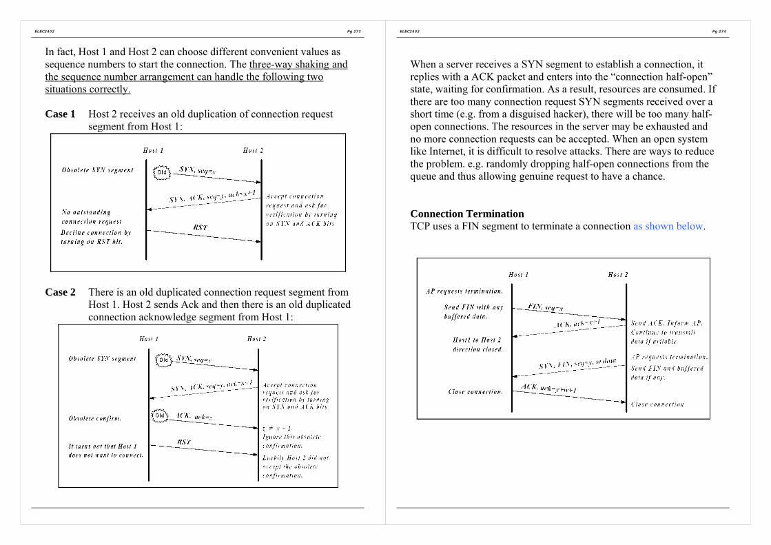
ELEC2402 Pg 273
In fact, Host 1 and Host 2 can choose different convenient values assequence numbers to start the connection. The three-way shaking andthe sequence number arrangement can handle the following twosituations correctly.
Case 1 Host 2 receives an old duplication of connection requestsegment from Host 1:
Case 2 There is an old duplicated connection request segment fromHost 1. Host 2 sends Ack and then there is an old duplicatedconnection acknowledge segment from Host 1:
ELEC2402 Pg 274
When a server receives a SYN segment to establish a connection, itreplies with a ACK packet and enters into the “connection half-open”state, waiting for confirmation. As a result, resources are consumed. Ifthere are too many connection request SYN segments received over ashort time (e.g. from a disguised hacker), there will be too many half-open connections. The resources in the server may be exhausted andno more connection requests can be accepted. When an open systemlike Internet, it is difficult to resolve attacks. There are ways to reducethe problem. e.g. randomly dropping half-open connections from thequeue and thus allowing genuine request to have a chance.
Connection TerminationTCP uses a FIN segment to terminate a connection as shown below.

ELEC2402 Pg 275
Can use the RST segment to abruptly terminating connection in bothdirections.
There are some special conditions regarding connection termination:
• Due to various reasons (e.g. the last FIN and ACK segments arerepeatedly lost, host crash), it is possible to have “half-open”connection. That is, one direction is disconnected but the otherdirection is not. Can have a “keepalive” timer. If there is noactivity on a connection for a long time, check the other end if itis still alive. If there is no response, terminate the connection.
• After closing a connection, TCP enters into a Timed Wait state. Itremains in this state for twice the maximum segment lifetime.This is to make sure that leftover segments from the closedconnection will die and therefore will not disturb the newconnection.
ELEC2402 Pg 276
TCP: Transmission of DataTCP uses a sliding window with variable length to controltransmission (flow control).
The following example illustrates the transmission procedure of TCP.Assume that a connection has already been made. The send sequencenumber starts at 0. Initially the receiver has a 4k buffer and thisinformation has been conveyed to the sender.
Figure F-24 Window management in TCP.

ELEC2402 Pg 277
When there is a change of buffer situation, the receiver advertises thenew window size to the sender. The sender transmits according to thenew window size. When the window size drops to 0, the sender stopstransmission except under the following conditions:
• May send urgent datae.g. use telnet to send a Unix command to a remote computerstarting a long process. Can use the key combination “CTRL-C”to terminate the process. Send this as urgent data.
• May send one byte to cause the receiver to re-advertise thewindow size and the next octet to receive. This is used to handledeadlocks due to the loss of window announcement.
Consider the following two situations:(i) The application supplies data to the sending TCP very slowly,
say a character at a time (e.g. Telnet).Each TCP segment from the sender carries only an octet of data.
TCP segment of 21 octets -> IP datagram of 41 octets.The receiver acknowledges the arrival of data.
TCP segment of 20 octets -> IP datagram of 40 octets.
When this octet of data has been consumed (, say by an editor),the receiver advertises the new window size.
TCP segment of 20 octets -> IP datagram of 40 octets.After processing the data, the editor echoes back.
TCP segment of 20 octets -> IP datagram of 40 octets.
Therefore, it takes 161 octets to complete the transmission ofonly one octet of data.
Efficiency=1/161=0.62% (extremely low)
ELEC2402 Pg 278
(ii) The application consumes data from the receiving TCP veryslowing, say a character at a time. This is the reverse of theprevious example but the consequence is the same. The buffer atthe receiving end runs out quickly (fast sending but slowconsumption). Eventually this reduces the window mechanism toa “stop-and-wait” situation. This is known as the Silly Syndrome.Can use a similar approach as in the previous example to analyzethe efficiency of this scenario.
The problem of the above situations can be reduced by:• Prevent the receiver from sending window update for a low
number of octets.• Wait until the window size reaches a certain size (e.g. half the
buffer size) and then advertise it to the sender.• Accumulate enough data at the sender before sending to the
receiver. e.g. When the first octet arrives at the sending TCP,send it. Do not send the subsequent octets until half of thewindow size or of the maximum segment size is reached, orwhen acknowledgement for the first octet comes.

ELEC2402 Pg 279
7.3 Congestion control at Transport LayerCan use the concept of window to achieve end-to-end flow control.The mechanism is similar to that in data link layer.
Problem: optimal window size depends on the bottleneck service ratealong the path and the round-trip time (RTT), which is thetime to send a packet to a destination node and receive areply from that node. In addition, these factors vary fromconnection to connection. Therefore use dynamic windowsize.
DECbit Scheme:
Figure F-25DECbit scheme.
In each packet header, there is a congestion-indication bit, which is setby an intermediate node experiencing congestion. When thedestination node issues an acknowledgement for packet, it copies thecongestion indication bit of the packet into the header of anacknowledgement packet.
ELEC2402 Pg 280
On receiving an acknowledgement, the source node inspects thiscongestion-indication bit and adjusts the transmission window size inthe following manner.
The source increases the window size until the bottleneck nodebecomes congested. Then it starts to receive acknowledgement withthe congestion-indicator set. It then reverts to reduce the window sizeuntil the congestion disappears. In this way, at equilibrium the sourcewindow size oscillates around the optimal value.
Can use implicit indication of congestion instead of including anexplicit congestion-indicator in a packet header. A source node keepson increasing the window size until there is re-transmission (whichmay be taken as an indication of data loss due to congestion). Then itstarts to reduce the window size and the cycle repeats.

ELEC2402 Pg 281
7.4 TCP congestion controlCan have a better way to increase and reduce the window size than asimple linear manner.
In TCP, the sender maintains a congestion window used to restrict theamount of data to be sent. The sender transmits data under therestriction of two windows: the advertised window from the receiverand the congested window.
A source node starts with 1 MSS (Maximum segment size) as thecongestion window size as shown in Figure F-26. Then increase thewindow size exponentially to a threshold value and then increaseslinearly beyond that threshold. The exponential phase is called the“slow-start” phase while the linear phase is called the “congestionavoidance” phase. The threshold is call the slow-start threshold,ssthresh which is initialized to half of the maximum allowablewindow size. On detecting a loss, ssthresh is set to half the currentwindow size and the window size is set to 1 MSS. Then the windowsize grows exponentially again up to the size of the receiver’s window.
Figure F-26An example of the Internet congestion algorithm
ELEC2402 Pg 282
Variants of this method are widely used in Internet (e.g. the Tahoealgorithm detects packet losses using timeouts.)
TCP uses sliding window of variable size for congestion control. Thedesign is based on an assumption that transmission is reliable.Therefore, packet loss is seldom due to transmission errors but largelydue to congestion at the host or at the network nodes. Therefore,detect congestion and adjust the issuing rate (slow down) according.
The TCP congestion control strategy runs into problem if theassumption is not true.e.g. In a wireless network, losses are largely due to transmissionproblem. Should try to re-transmit as quickly as possible on thedetection of a loss, not to slow down.

ELEC2402 Pg 283
TCP: timeoutA re-transmission timer is used to stop the “forever-waiting-for-acknowledgement” deadlock situation. But how long should the timerset for? It should be set according to the round-trip-time, RTT, whichis the time to send a packet to a destination node and receive a replyfrom that node. But RTT fluctuates according to traffic conditions.
Figure F-27 (a) Probability density of acknowledgement arrival timesin the data link layer. (b) Probability density of acknowledgement arrival
times for TCP.
ELEC2402 Pg 284
In data link, can set the timeout value around the high peak (i.e.20msec). Delay is quite is quite predictable for a point-to-pointconnection.
In TCP, RTT spreads over a wider range as shown in Figure F-27(b)rather than (a). This is because TCP has to deal with a wide diversityof underlying physical networks. It has to tolerate a wide range ofdelay, throughput and packet loss rate. Therefore RTT tends tofluctuate. In the above example, if set the timeout at 20 msec, therewould be quite a significant amount of unnecessary retransmission ofsegments as well as unnecessary long waiting intervals for lostsegments.
Compounding the problem further, the network traffic situation maychange rapidly making a static timeout algorithm ineffective.
Adjust the timeout values according to the network performance.
Maintain a variable RTT for each connection. RTT holds the bestcurrent estimate of the round-trip-time for the TCP connection. Onsending a segment, start a timer which is used both for measuring howlong an acknowledgement comes and for timeout operation for re-transmission. When the acknowledgement comes, adjust RTTaccording to the remaining value of the timer. The new timeout valueis set according to the calculated RTT.

ELEC2402 Pg 285
8. UDP Connectionless ServicesUDP allows AP to encapsulate data directly in IP datagrams and sendthemWithout establishing a connection beforehand. Essentially, UDP haslittle to do. It puts the port information in a header. Format of a UDP:
Figure F-28 The UDP header.
ELEC2402 Pg 286
9. Network applications
Figure F-29 A simple Client-Server Model of TCP/IP.
Network hardware and protocol software provides a communicationtransport base for application programs in different computers. Thereare at least two application programs involving in a communication.One initiates the communication actively while the other one waitspassively. -> Client-Server model as shown in Figure F-29.
An application program interacts with the communication protocolsoftware in an OS through a well-defined Application ProgramInterface (API) which defines a set of operations that an applicationcan perform in order to interact with the protocol software. In mostOS, the API is in the form of a set of procedures with parameters.Socket API is widely used. The socket API is provided either as OSprocedures (native sockets) or library procedures. A socket can beseen as a network communication end-point. An application mustrequest the OS to create a socket before communication can start. Thesystem then returns a descriptor to the application. However, this

ELEC2402 Pg 287
newly created socket does not have a local address. A server uses thebind procedure to obtain a local address (protocol port number) atwhich the server will wait for contact. The Berkeley Socketprocedures/primitives are shown in the following table.
Primitive Meaningsocket Creates a new socket (communication end point)close Terminate the use of the socket. Any connection on that socket
will be closed first.bind Server assigns a local address to an unbound socket.listen Server places a bound socket in the passive mode to wait for
clients to make connection request. It also specifies the requestquene size for this socket.
accept For connectionless service, server can accept messages from abound socket.For connection-oriented service, must listen to wait for aconnection request. If there is no request in the quene, theserver is blocked. If there is a request, a new socket is createdand the new descriptor is sent to the client that has made thatrequest. Use this socket for communication between the serverand that client. When the connection is closed, the server usesthe original socket to accept new connection request.
connect For connection-orient transport protocol, initiates a connectionat the transport level to a specified server which has calledaccept.For connectionless transport protocol, merely mark the socketas connected and note down the server address. Then no needto specify the destination address for each message.
send Send data over a connected socket.sendto Send data to an unconnected socket. The destination address is
also supplied,.sendmsg Send a structured message to an unconnected socket. The
message contains the destination address.recv Receive data from a connected socket.recvfrom Receive data from an unconnected socket. Source address of
the message is also obtained.recvmsg Receive a structured message from an unconnected socket.
This message contains the source address.
ELEC2402 Pg 288
close Release the connection
Applications can also use read and write to transfer data over aconnected socket. Therefore, to an application program, the socketAPI can be taken as an I/O interface. The socket API follows theconventional way of I/O access: open-read-write-close as shownbelow.
Figure F-30 A simple Client-Server Example.

ELEC2402 Pg 289
Section G
The Application Layer (Layer 7)
1. The Domain Name System
2. Electronic Mail
3. Multimedia
ELEC2402 Pg 290
The Application Layer (Layer 7)The layers below the application layer are there to provide reliabletransport, but they do not do real work for users.
Even in the application layer there is a need for support protocols, toallow the applications to function. Accordingly, we will look at one ofthese before starting with the applications themselves. The item inquestion is DNS, which handles naming within the Internet. After that,we will examine two real applications: electronic mail and multimedia.
1. The Domain Name System
Although programs theoretically could refer to hosts, mailboxes,and other resources by their network (e.g., IP) addresses, theseaddresses are hard for people to remember. Also sending e-mail toIP address means that if the ISP or organization moves the mailserver to a different machine with a different IP address, the e-mailaddress has to be changed ASCII names to decouple machine name from machineaddresses.
DNS (RFCs 1034 and 1035) – a hierarchical, domain-based namingscheme and a distributed database system for implementing themachine naming scheme.

ELEC2402 Pg 291
1.1 The DNS Name SpaceThe Internet is divided into over 200 top-level domains, whereeach domain covers many hosts. Each domain is partitioned intosub-domains, and these are further partitioned, and so on asshown in Figure G-1.
Figure G-1 A portion of the Internet domain name space.
Domain names are case insensitive, so edu, Edu and EDU meanthe same thing. Component names can be up to 63 characterslong, and full path name must not exceed 255 characters.
To create a new domain, permission is required of the domain inwhich it will be included. For example, if a VLSI group is startedat Yale and wants to know as vlsi.cs.yale.edu, it has to getpermission from whoever manages cs.yale.edu.
ELEC2402 Pg 292
1.2 Resource Records
Every domain, whether it is a single host or a top-level domain,can have a set of resource records associated. For a single host,the most common resource record is just its IP address, but manyother kinds of resource records also exist.
A resource record is a five-tuple. Although they are encoded inbinary for efficiency, in most expositions, resource records arepresented as ASCII text, one line per resource record. The formatis as follows:
Domain_name Time_to_live Class Type Value
Figure G-2 A portion of a possible DNS database for cs.vn.nl

ELEC2402 Pg 293
The meaning of the Type field tells what kind of record this is.The most important types are listed in Figure below:
Figure G-3 The principal DNS resouce record types for IPv4.
ELEC2402 Pg 294
1.3 Name Servers
To avoid overloading a single name server for entire DNSdatabase, the DNS name space is divided into non-overlappingzones.
Each zone contains some part of the tree and also contains nameservers holding the information about that zone.
When a resolver has a query about a domain name, it passes thequery to one of the local name servers. If the domain beingsought falls under the jurisdiction of the name server, such asai.cs.yale.edu falling under cs.yale.edu, it returns theauthoritative resource records.
For example, a resolver on flits.cs.vn.nl wants to know the IPaddress of host Linda.cs.yale.edu. run through eight steps asshown below:
Figure G-4 How a resolver looks up a remote name in eight steps.

ELEC2402 Pg 295
2. Electronic Mail
2.1 Architecture and Services
Email system consist of two subsystems:(i) User Agents
User Agent is normally a program that accepts a variety ofcommands for composing, receiving, and replying tomessages, as well as for manipulating mailboxes.
(ii) Message Transfer agentsMove the messages from the source to destination.
2.2 Message Formats
(i) ASCII e-mail messages are defined in RFC 822.
Figure G-5 RFC 822 header fields related to message transport.
ELEC2402 Pg 296
Figure G-6 Some fields used in the RFC 822 message header.
(ii) MIME – The Multipurpose Internet Mail Extensions (RFCs2045-2049)
Defines encoding rules for non-ASCII messageswithout deviating from RFC 822, MIME message canbe sent using the existing mail programs and protocols.
2.3 Message Transfer
Within the Internet, e-mail is delivered by having the sourcemachine establish a TCP connection to port 25 of the destinationmachine. Listening to this port is an e-mail daemon that speaksSMTP (Simple Mail Transfer Protocol) which is a simple ASCIIprotocol.

ELEC2402 Pg 297
2.4 Final Delivery
Many people access the Internet by calling their ISP over amodem, if the connection breaks down, e-mail cannot send to theclient machine.=> a message transfer agent on ISP machine accepting e-mail
for its customers and store it in their mailboxes on an ISPmachine.
Two protocols are available:POP3 and IMAP.
Figure G-7 A comparison of POP3 and IMAP.
ELEC2402 Pg 298
3. Multimedia
3.1 Introduction to Digital Audio
The frequency range of human ear runs from 20 Hz to 20,000 Hz.Audio CDs are digital with a sampling rate of 44,100 samples/sec,enough to capture frequencies up to 22,050 Hz and the samplesare 16 bits which allow only 65,536 distinct values. To senduncompressed audio CDs over network requires 1.411 Mbps forstereo (almost a full T1 channel bandwidth).=> a compression method required.
3.2 Audio Compression
Popular one is MP3 (MPEG audio layer 3). Audio compression isdone in one of two ways. In waveform coding the signal istransformed mathematically by a Fourier transform into itsfrequency components. The other way, perceptual coding,exploits certain flaws in the human auditory system to encode asignal in such a way that it sounds the same to a human listener,even if it look quite different on an oscilloscope.
MP# can compress a stereo rock’n roll CD down to 96k bps withlittle perceptible loss in quality. For a piano concert, at least 128kbps re needed.
3.3 Streaming AudioThe actual transmission is usually with a protocol like RTP (areal-time protocols layered on top of UDP, so packets may belost.).

ELEC2402 Pg 299
The server is pushing the data to the client machine to reduceunnecessary data requests and the client plays the media throughthe client’s buffer rather than directly from the network.
Figure G-8 The media player buffers input from the media server andplays from the buffer rather than directly from the network.
ELEC2402 Pg 300
Section H
Network Security
1. Aspects of network security
2. Encryption
3. Digital signature
4. Authentication protocols
5. E-Mail Security
6. Web Security
7. Packet filtering and firewall

ELEC2402 Pg 301
1. Aspects of network security• Data integrity
Received data = transmitted data?Checksum or CRC; but not 100%
• Data availabilityProtection against illegal access to dataSimple password may not work due to eavesdropping orwiretapping.Masquerading:
Replace the original message sequence with new messagesequence
• Data confidentiality and privacyProtection against unauthorized access.Encode data with special algorithm such that only the receivercan decode it.-> Cryptography:
encryption/decryption (encipherment/decipherment).
ELEC2402 Pg 302
2. Encryption
Message before encryption is called plaintext and that after encryption,ciphertext. Most encryption methods put the encryption information ina encryption key which is known only to the sender and the recipient.
Figure H-1 The encryption model (for a symmetric-key cipher)
Three basic encryption techniques
(i) SubstituteReplace a plaintext alphabet with another alphabet according tocertain rule.e.g. simple shifting by places. (encryption key = 2)
Plain text: computer networkCiphertext: eqorwvgt”pgvyqtm
If the number of alphabets is n, the number of possible keys(including no shift) is n. very easy to crack.

ELEC2402 Pg 303
Can use a more complicated scheme, e.g. use a random mix ofthe plaintext alphabet. Then there are n! possible keys. Still quiteeasy to crack. Can look for some frequent groups of informationaccording to statistics.
If the plaintext is in plain English, can look for the mostfrequency used letters (a,o), 2-letter combinations (in, th) or 3-letter combinations (the, and),…
(ii) TransposeReorder the information (alphabet) in a plaintext.e.g. Divide the plaintext into groups of n characters. Theciphertext is formed by first taking all the first characters in eachgroup, then all the second characters,…
Encryption key=4Plaintext: computer networkCiphertext: cu wotnomeerprtk
Same problem as the substitution method.
ELEC2402 Pg 304
(iii) One-Time PadsThis technique has been known for decades. First choose a trulyrandom (not pseudo random) bit string as the key. Then convertthe plaintext into a bit string, for example by using its ASCIIrepresentation. Finally, compute the XOR (exclusive OR) ofthese two strings, bit by bit. The resulting ciphertext cannotbroken, because in a sufficiently large sample of ciphertext, eachletter will occur equally often, as will every digram, every ingram,and so on. (Disadvantage: In order to send k amount of data, youneed a key with length k.)
Figure H-2 The use of a one-time pad for encryption and thepossibility of getting any possible plaintext from the ciphertext by the use
of some other pad.
Most encryption systems uses product cipher method which is acombination of the above first two techniques working at the bit level.e.g. Data Encryption Standard (DES) which is a block cipher. DESworks on blocks of 64 bits with 56-bit encryption key.

ELEC2402 Pg 305
Problem:Same key for encryption and decryption. Therefore, the keymust be agreed between the sender and recipient beforesecured transmission can start. This is also called private-key (secret-key) encryption. The key must be kept as asecret. But, for security reason, may want to change keysfrom time to time, say daily. It is not secure to send keythrough network. This makes key distribution a big problem.
Public key (Rivest, Shamir & Adelman algorithm, RSA)
RSA uses two different keys: public key (for encryption) and privatekey (decryption).
There are two important properties with these two keys:• A message encrypted with the public key can be decrypted only
with private key.• The private key cannot be derived (other than brute force attack)
from the public key.
A host can change the public key and the private key and announce itspublic key. Although the public key is widely known but this host isthe only one holding the private key and therefore, it is the only onewhich can decrypt the message encrypted by the announced publickey.
Guard against eavesdropping but how about if someone used theavailable public key to send a forged message.-> message authentication (i.e. verification of the identity of messagesender) -> digital signature)
ELEC2402 Pg 306
3. Digital signatureThe private key and the public key have another important property: amessage encrypted with the private key can be decrypted with thepublic key.
Public-Key SignaturesSuppose the sender Host 1 encrypts the message with its private keys.If the recipient host 2 can decrypt the message with host 1’s publickey, the sender must be host 1 which is the only one holding theprivate key of host1.
Can have double encryption: one for authentication and one for thenormal encryption against eavesdropping.
Figure H-3 Digital signatures using public-key cryptography
E(D(P)) = P and D(E(P)) = PD = decrypt E = encrypt

ELEC2402 Pg 307
Encrypting the whole message for authentication is very time-consuming. Therefore, encrypt only a small message (e.g. amathematical function of the plaintext, e.g. CRC) with the private keyof the sender into a digital signature. The digital signature is thenappended as a trailer to the original plaintext. This is in an analogy ofhaving the sender “sign” the message and the recipient verifysignature.
Message Digests (to ensure messages do not alter by intruder)One criticism of signature methods is that they often couple twodistinct functions: authentication and secrecy. Often, authentication isneeded but secrecy is not. An authentication scheme that does notrequire encrypting the entire message called message digest isrequired.
This scheme is based on the idea of a one-way hash function that takesan arbitrarily long piece of plaintext and from it computes a fixedlength bit string. This hash function, MD, called a message digest, hasfour important properties:
Given plaintext P, it is easy to compute MD(P). Given MD(P), it is effectively impossible to find P. Given P no one can find P’ such that MD(P’)=MD(P).
(Cannot be achieve in practice - the birthday attack) A change to the input of even 1 bit produces a very
different output.Examples are MD5 and SHA-1 (Secure Hash Algorithm) algorithms.
Figure H-4 Use of SHA-1 and RSA for signing nonsecret messages
RSA = Rivest, Shamir,Adleman – the threediscoverers
ELEC2402 Pg 308
4. Authentication protocols
Key Distribution Centre (KDC) / Certificate Authority (CA)In e-commerce, may have a large number of clients and many serviceproviders. If a client needs a key for each service, e.g. one key for abank and another key for a supermarket, key management becomes aburden.
register with a trusted party (e.g. Post Office in HK) andget a key for each session of transactions with a service. Key Distribution Centre (KDC) / Certificate Authority
(CA)
Authentication using Kerberos(Kerberos = A multiheaded dog in Greek mythology that used to guard theentrance to Hades.)Kerberos is an authentication system commonly used in many realsystems (including Windows 2000). It does not use a public key but arandom session key for each session.
There are three parties involved:1) CA: the trusted party offering authentication service.2) Application server (S): offers an application service and is also
known as end server.3) Client (C): usually can be viewed as composed of a user (U) and
a workstation (WS) through which the user interacts with CA andS.

ELEC2402 Pg 309
Figure H-5 The operation of Kerberos V4.
In Kerberos, users and application servers must register with the CA.CA maintains a database containing the password of each user and theprivate key of each application server.
When a user request for service, it must first obtain a ticket from CAand presents this ticket to a server with proof that the ticket wasoriginally issued to the user (i.e. authentication). Kerberosauthentication protocols ensure that the service access operation isdone in a secured manner. There are three typical phases:
1) Client requests ticket from CA in order to access a service.2) CA issues ticket with session key for that service.3) Client requests the server for service with authentication and
session key.
There are two servers in the CA.1) Authentication server (AS)
Verifies users during login and allows it to access TGS.2) Ticket granting server (TGS)
Issues “proof of identity ticket” to allow a client to access the endserver.
ELEC2402 Pg 310
Note: since TGS provides a service of issuing tickets to users so thatthey can be authenticated to access services of the appropriate endservers. Therefore, TGS can also be accessed by means of the serviceaccess protocol.

ELEC2402 Pg 311
5. E-Mail Security
One example: PGP (Pretty Good Privacy):• Essentially the brainchild of one person, Phil Zimmermann.
• A complete e-mail security package that provides privacy,authentication, digital signatures, and compression, all in aneasy-to-use form.
• Encrypts data by using a block cipher called IDEA(International Data Encryption Algorithm), which uses 128-bitkeys.
• Complete package, including all the source code, is distributedfree of charge via the Internet and is widely used.
• Supports text compression, secrecy, and digital signatures.
ELEC2402 Pg 312
6. Web Security
6.1 SSL – The Secure Sockets Layer
When the Web burst into public view, it was initially used for justdistributing static pages. However, before long, some companies gotthe idea of using it for financial transactions, such as purchasingmerchandise by credit card, on-line banking, and electronic stocktrading. These applications created a demand for secure connections.
SSL builds a secure a secure connection between two sockets,including:
i. Parameter negotiation between client and server.ii. Mutual authentication of client and server.
iii. Secret communication.iv. Data integrity protection.
The positioning of SSL in the usual protocol stack is illustrated inFigure H-6 effectively, it is a new layer interposed between theapplication layer and the transport layer, accepting requests from thebrowser and sending them down to TCP for transmission to the server.
Figure H-6 Layers (and protocols) for a home user browsing with SSL.

ELEC2402 Pg 313
The SSL consists of two subprotocols, one for establishing aestablishing a secure connection and one for using it.
Below is how secure connections are established as illustrated inFigure H-7.
Figure H-7 A simplified version of the SSL connection establishmentsubprotocol.
ELEC2402 Pg 314
1. Alice sends a request to Bob to establish a connection,specifying the SSL version Alice has and her preferenceswith respect to compression and cryptographic algorithms.
2. Bob makes a choice among the various algorithms thatAlice can support and sends his own nonce, RB.
3. Bob sends a certificate containing his public key. If thiscertificate is not signed by some well-known authority, healso sends a chain of certificates that can be followed backto one. All browsers, including Alice’s, come preloadedwith about 100 public keys, so if Bob can establish a chainanchored at one of these, Alice will be able to verify Bob’spublic key. At this point Bob may send some othermessages (such as a request for Alice’s public-keycertificate)
4. When Bob is done. He sends message 4 to tell Alice it is herturn.
5. Alice responds by choosing a random 384-bit premaster keyand sending it to Bob encrypted with his public key. Theactual session key used for encrypting data is derived fromthe premaster key combined with both nonces in a complexway.
6. Alice tells Bob to switch to the new cipher.7. Alice finished with the establishment sub-protocol.8 and 9 Bob then acknowledges her.
However, although Alice knows who Bob is, Bob does not know whoAlice is (unless Alice has a public key and a corresponding certificatefor it, an unlikely situation for an individual). Therefore, Bob’s firstmessage may well be a request for Alice to log in using a previouslyestablished login name and password. The login protocol, however, isoutside the scope of SSL.

ELEC2402 Pg 315
For actual transport, a second subprotocol is used, as shown in FigureH-8.
Messages from the browser are first broken into units of up to 1KB. Ifcompression is enabled, each unit is then separately compressed. Afterthat, a secret key derived and premaster key is concatenated with thecompressed text and the result hashed with the agreed-on hashingalgorithm (usually MD5). This hash is appended to each fragment asthe MAC. The compressed fragment plus MAC is then encrypted withthe agreed-on symmetric encryption algorithm. Finally, a fragmentheader is attached and the fragment is transmitted over the TCPconnection.
Figure H-8 Data transmission using SSL.
ELEC2402 Pg 316
7. Packet filtering and firewall
Firewalls forced everyone entering or leaving the castle to passs overa single drawbridge, where they could be inspected by the I/O police.With networks, the same trick is possible: a company can have manyLANs connected in arbitrary ways, but all traffic to or rom thecompany is forced through an electronic drawbridge (firewall), asshown in Figure H-9.
The firewall in Figure H-9 has two components: two routers that dopacket filtering and an application gateway. Simpler configurationsalso exist, but the advantage of this design is that every packet musttransit two filters and an application gateway to go in or out. No otherroute exists.
In Figure H-9, most likely the packet filter on the inside LAN checksoutgoing packets and the one the outside LAN checks incomingpackets. Packets crossing the first hurdle go to the application gatewayfor further examination.
Figure H-9 A firewall consisting of two packet filers and anapplication gateway.

ELEC2402 Pg 317
Packet filters are typically driven by tables configured by the systemadministrator. These tables list sources and destinations that areacceptable, sources and destinations that are blocked, and default rulesabout what to do with packets coming from or going o other machines.
The second half of the firewall is the application gateway. Rather thanjust looking at raw packets, the gateway operates at the applicationlevel. a mail gateway, for example, can be set up to examine eachmessage going in or coming out and check if there is virus in the email.
ELEC2402 Pg 318
Section I
Example Networks
1. ISDN (Integrated Services Digital Network)
2. Asynchronous Transfer Mode (ATM)

ELEC2402 Pg 319
1. ISDN (Integrated Services Digital Network)
1.1 IntroductionTelephone system:
• For more than a century, the primary internationalcommunication infrastructure has been the telephone.
• It was designed for analog voice transmission and is inadequatefor modern communication need such as data transmission(interactive & non-interactive) facsimile, video and etc.,
• Thus, these demands lead to the development of a new advanceddigital system, the ISDN, to replace a major portion of theworldwide telephone system by early 21st century.
• The primary goal of ISDN is the integration of voice and non-voice services.
• ISDN is basically a redesign of the telephone system &coordinated by CCITT.
• The key ISDN recommendations were approved in 1984, withrefinements in 1988.
• Figure I-1 lists some of the key recommendation (Decina, 1986)
ELEC2402 Pg 320
Number Title1.120 Integrated Services Digital Networks (ISDN)1.210 Principles of telecommunication services supported by an
ISDN1.211 Bearer services supported by an ISDN1.310 ISDN network functional principles1.320 ISDN protocol reference manual1.411 ISDN user/network interfaces – reference configurations1.412 ISDN user/network interfaces – interface structure and
access1.420 Basic network/user interface1.421 Primary rate network/user access1.430 Basic user/network interface – Layer 1 specification1.431 Primary rate user/network interface – Layer 1 specification1.440 ISDN user/network interface Data Link Layer protocol –
general aspects1.441 ISDN user/network interface Data Link Layer specification1.450 ISDN user/network interface Layer 3 – general aspects1.451 ISDN user/network interface Layer 3 -specification
Figure I-1 Some of the principal CCITT ISDN Recommendations

ELEC2402 Pg 321
1.2 ISDN Services
=> voice / speech communication services:• additional enhanced features:e.g., - instant call setup,
- display the caller’s telephone number, name, andaddress on a display while ringing, or even the caller’sdatabase record to be displayed on screen.
- call transfer and forwarding to any number worldwide;conference call worldwide; capable of leavingmessages while the callee is absence; an automaticwakeup call service; etc.
=> data transmission services:• allow users to connect their ISDN terminal or computer to any
other one in the world. (at present, such connections arefrequently impossible internationally due to incompatiblenational telephone systems)
• capable of broadcasting message through the network to theclosed-user-group users or all the users.
• closed-user-group features acting as a private network, no callsfrom outside the group can come in (except in carefullycontrolled ways), and the member o group can only call othermembers of the group.Attractive to many corporate, government, diplomatic andmilitary agencies for privacy and security reasons.
ELEC2402 Pg 322
Videotex• Videotex is interactive access to a remote database by a person at
a terminal.• On-line telephone directory assistance, as to begin to abolish all
the telephone books and information operators (at enormoussavings) by providing each subscriber with a small terminal foraccessing the on-line telephone book.
• On-line yellow-page services:The complete process of purchasing: selecting a company,ordering products, invoicing, and charging can be done throughthe Videotex service. Other examples such as the airline, hotel &restaurant reservations, bank-by-terminal, and etc.
Teletex• Electronic mail• Facsimile (FAX)
Telemetry or alarm• gas and electricity meters reading (where only a few digits are
needed to be collected)• smoke and fire alarm detection• medical alarm• etc.

ELEC2402 Pg 323
1.3 Evolution of ISDNThere are currently three distinct system components which wouldhave a major influence on the ISDN evolution towards the final ISDN,as shown in the figure below.
Packetswitchingnetwork
Evolutionof ISDN
Public switched network(the telephone system)
CCIS network(Common ChannelInteroffice Signaling)
In-band signaling of the public switched network• The analog voice telephone system originally sent all its control
information in the same 4 kHz channel used by voice. Pure tonesat various frequencies were used for signaling by the systemitself; => i.e., in-band signaling.
• As a result, users could inter with the internal signaling systemby generating a sequence of appropriate tones. This leads toserious commercial and individual billing fraud.
• Solution: CCIS
ELEC2402 Pg 324
CCIS (Common Channel Interoffice Signaling)
• To eliminate the problems caused by in-band signaling, AT&Tbuilt and installed a packet switched network, the CCIS, separatefrom the main public switched network.
• CCIS runs at 2.4k bps, and it was designed to move the signalingtraffic out-of-band.
• With CCIS, when an end office needed to set up a call, it chose achannel on an out-going trunk of the public switched network.Then it sent a packet on the CCIS network to the next switchingoffice along the chosen route telling which channel had beenallocated. This CCIS node then chose the next outgoing trunkchannel, and reported it on the CCIS network.
• Thus, the management of the analog connections was done on aseparate packet switched network to which the users had noaccess.
• CCIS was then regarded as a great success, and was soon used bymore and more applications.The four major uses now are:
a) Call setup, routing and terminationb) Internal database access
e.g. verification of telephone credit and numbers.c) Network operations and support.
e.g. optimum route.d) Accounting and billing.

ELEC2402 Pg 325
The local loop has bandwidth of about 2Mbps for 80 % of the loopshorter than 7 or 8 km, and somewhat less on longer ones.
Packet switched network
packet networks
CCIS networkISDNExchange
ISDNExchange
Carrier’s equipment
ISDN Interface using twisted pairs
(a)
Customer’sequipment
ISDNTerminal
Customer’sequipment
ISDNTerminal
Integrated ISDN Transportnetwork
ISDNExchange
ISDNExchange
(b)
ISDNTerminal
ISDNTerminal
Figure I-2 (a) Initial stage of ISDN evolution. (b) Later stage.
ELEC2402 Pg 326
Packet switching network• For data transmission, such as remote database access.• Costs depend primarily on traffic volume, not the connect time.• Growth in use since the mid 1970 as the packet switching
networks are available commercially.
Thus, the current telephone system really has three distinctcomponents:
a) The analog public switched networkb) CCIS for controlling the voice networkc) Packet switching networks for data
In fact, the ISDN will thus be evolved from the current telephonesystem. This means that ISDN was designed from the beginning tolive with the limitation of the existing local loops and the voice, CCISand packet networks.
• The first step towards ISDN was to define and standardize theuser-to-ISDN interface.
• The next step was to slowly start replacing existing end officeswith ISDN exchanges that support the ISDN interface.As shown in Figure I-2(a), those users connected to an ISDNexchange can use ISDN services on call to other ISDN users,even though these calls use the facilities of the existing networks.
• Eventually, the existing transmission and switching networks willbe replaced by an integrated one, as shown in Figure I-2(b);which is expected to be completed by the 21st century.

ELEC2402 Pg 327
ISDNTerminal
ISDNAlarm
ISDNTelephone
Customer’s equipment
NT1Tocarrier’sinternalnetwork
ISDNExchange
Carrier’s equipment
T U
Digitalbitpipe
(a)
Customer’s office Carrier’s office
TE1ISDN
Terminal
NT1: network boundary
NT2: customer PBX
TE1: ISDN terminal
TE2: non-ISDN terminal
TA: terminal adapter
TA
Customer’s equipment
NT1Tocarrier’sinternalnetwork
ISDNExchange
Carrier’s equipment
T U
Digitalbitpipe
(B)
Customer’s office Carrier’s office
TE1ISDN
Telephone
LANGateway
NT2ISDNPBX
NonISDN
Terminal
RS
S
S
Figure I-3 (a) Example ISDN system for home use. (b) Example ISDNsystem with a PBX for use in large businesses.
CCITT has defined 4 reference points; R S T and U :U: the connection between the ISDN exchange and NT1.T: is what the connector on NT1 provides to the customer.S: is the interface between the ISDN PBX and the ISDN terminalsR: is the connection between the terminal adapter and non-ISDN
terminals. Many different kinds of interfaces will be used at R.e.g. RS449, X.21 instead of RS232-C
ELEC2402 Pg 328
1.4 ISDN system architecture• Interface between the customer and the telephone company• The key idea behind ISDN is that of the digital bit pipe – a
conceptual pipe between the customer and the carrier throughwhich bits flow.
• Whether the bits originated from a digital telephone, a digitalterminal, a digital facsimile machine, or some other device isirrelevant.All that matters is that bits can flow through the pipe in bothdirections.
Digital bit pipe {also refer to {Figure I-3}• Support multiple independent channels (using TDM)• Two principal standards:
a) A low bandwidth for home useb) Higher bandwidth for business use (i.e. consists of multiple
channels that are identical to the home use channel).• Multiple digital-bit-pipes are possible for large business use
NTI (network terminating device [1])• As shown in Figure I-3(a) &(b)• NTI box has a connector on it into which a passive bus cable can
be inserted.• Up to 8 ISDN telephones, terminals and other devices can be
connected to the bus cable.• It contains electronics for network administration, local and
remote loopback testing, maintenance, and performancemonitoring.
• e.g. ISDS terminal or device addressing.• It also contains logic for contention resolution: if several devices
try to access the bus at the same time, it can determine which oneshould win.

ELEC2402 Pg 329
• However, in term of the OSI model, NTI is primarily a physicallayer device.It concerns with the shape of the plug and the voltages used torepresent bits, but knows nothing about how frames are built ontop of the raw bit stream.
• The model of Figure I-3(a) is inadequate for large businessbecause more telephone conservations are likely going onsimultaneously than the bus can handle.Thus the model of Figure I-3(b) is used; in which an additionaldevice – NT2 is required.
NT2• NT2 – called a PBX (Private Branch exchange).• NT2, or the ISDN PBX provides real interface for telephones,
terminals and other devices.• Conceptually similar to an ISDN exchange in a smaller scale.• e.g. calls between two telephones or terminals within the
company, usually dialed using 4 digit extension numbers, areconnected inside the PBX, without the carrier’s ISDN exchangebeing aware.
• When an employee dials “9” (or some other code) to get anoutside line, the PBX allocates a channel on the outgoing digitalbit pipe and connects the caller to it. If no channel is available,the caller gets a busy signal.
• PBXes cover at least layers 1 through 3 in the OSI model.• An ISDN PBX (i.e., NT2) can directly interface to ISDN
terminals and telephones.• For non-ISDN terminals or devices, terminal adapters are
required such that it speaks RS232-C to the terminal and speaksISDN to the PBX.
ELEC2402 Pg 330
1.5 Digital PBX
• PBX design is a large and complex area, and much of thetechnology is proprietary.
• 1st generation PBXes:were patch panels run by a human operators.
• 2nd generation PBXes:employed electromechanical relays making the connection
instead of a human operator.
• 3rd generation PBXes – so called the modern PBX.Also known as PABX (Private Automatic Branch eXchange)Or CBX (Computerized Branch eXchange).As shown in Figure I-4.

ELEC2402 Pg 331
The third generation PBX: the PABX or CBX• The heart of the digital PBX is a circuit switch into which
modules (e.g. for ISDN devices, for RS232-C terminals, etc) canbe inserted.
Line modulefor ISDNdevices
Line modulefor RS-232-C
terminals
Line modulefor analogtelephones
To ISDN exchange
Trunk module
Control unit
Services unitISDN bit stream
Switch
⎫⎪⎪⎬⎪⎪⎭
Figure I-4 Block structure of a digital PBX.
• Each module card interfaces with some class of device andproduces an ISDN bit stream as output
• An ISDN module does not have much work to do; but a modulefor analog telephone must digitize the signal in ISDN format.
• Trunk modules connect to the ISDN exchange.• The control unit is general-purpose computer that runs the PBX.
e.g., when a telephone is picked up or a terminal powered on, thecontrol module gets an interrupt from the appropriate linemodule. The control unit then collects the digits of thenumber called, and sets up the switch to create a circuitbetween the calling and called devices.
• The services unit provides dial tones, busy signals, and otherservices for the control unit.
ELEC2402 Pg 332
Two kinds of switches are in common use(i) crosspoint switch(ii) time division switch
(i) crosspoint switch as shown in Figure I-5
Outputs0 11 22 33 44 55 66 77
Inpu
ts
76543210
Potentialconnection
Outputs0 11 22 33 44 55 66 77
Inpu
ts
76543210
Actualconnection
0 connected with 41 connected with 72 connected with 6
(a) (b)Figure I-5 (a) A crosspoint switch with no connections. (b) A crosspoint
switch with three connections setup.
• In a PBX with n inputs lines and n output lines (ie., n full duplexlines); -> n2 intersections that may be connected bysemiconductor switch. Figure I-5(b) shows a setup of threeconnections.
• The crosspoint switch implements circuit switching by making adirect electrical connection with microseconds, automatically.
• Bus, the number of crosspoints grows as the square of thenumber of lines into the PBX.

ELEC2402 Pg 333
Assuming all lines are full duplex and no self-connections, onlythe crosspoints above the diagonal are needed. Still, n(n-1)/2cross points are needed. e.g., for n=10000, we need 499, 500cross points.This may be possible using VLSI technology, but having 1000pins on a single chip is not possible.Nevertheless, it is possible to build feasible multistage switches.
ELEC2402 Pg 334
(ii) time division switch• the n input lines are scanned in sequence to build up an input
frame with n slots• each slot has k bits.
n input linesTime slot
interchanger
Input frame
Time slots
0 1 2 3 4 5 6 7
Counter
Input frame
4 7 6 3 0 5 2 1
n output lines
0 1 2 3 4 5 6 70 1 2 3 4 5 6 7Time slots
RAM buffer ofn k-bit words
n word mapping table
01234567
47630521
01234567
47630521
full duplexconnection
To circuitswitched
Read-in:in sequence
Read-out:In order according tothe mapping tablei.e. direct addressing
Figure I-6 A time division switch.
• For ISDN PBXes, k=8 bits, with 8,000 frames built andprocessed per second. (ISDN uses PCM standard. I.e., 64kbps pervoice channel)
• The heart of the time division switch is the time slot interchanger,which accepts input frames in which the time slots have beenrecorded.
• As shown in Figure I-6, input slot 4 is output first, then slot 7 andso on.Finally, the output frame is de-multiplexed, with output slot 0(input slot 4) going to line 0 and so on. That ism the switch hasmoved a byte from input line 4 to output line 0; 7 -> 1 and so on.

ELEC2402 Pg 335
• Thus it is a circuit switch arrangement, even though there are nophysical connections.
• The time slot in interchanger works as follows:When an input frame is ready to be processed, each slot (i.e., byte)is written into a RAM buffer inside the interchanger.The slots are written in order, so buffer word I contains slot i.After all the slots of the input frame have been stored in thebuffer, the output frame is constructed y reading out the worksagain, but in a different order.A counter goes from 0 to n-1(0-7 say). At step j(4 say) thecontents of word j of a mapping table is read out and used toaddress the RAM table.e.g., if word 0 of the mapping table contains a 4, word 4 of theRAM buffer will be read-out first, and the first slot of the outputframe will be slot 4 of the input frame, as shown in Figure I-6.
• That is, the contents of the mapping table determine whichpermutation of the input frame will be generated as the outputframe, and thus which input line is connected to which outputline.If a duplex connection is setup between slots I and j, slot I in themapping table gets value j and slot j get value i.
• The mapping tables are linear in the number of lines, rather thanquadratic as for crosspoint switches.
• The read-in and read-out operation must be performed within oneframe period of 125 µsec ((=8bits/64 bps) for all n lines.e.g. if each memory access to the RAM take T µsec, the time
needed to process a frame is 2nT µsec = 125 µsecFor a memory with T=100 µsec cycle time, we can supportn=625 lines.
• It is possible to use multistage switches for handling largenumber of lines.
ELEC2402 Pg 336
1.6 The ISDN interface
• Remember that the goal of ISDN is to present the user with adigital pipe at either T or S reference point.
• Be aware that the term “interface” has a different meaning in theISDN would than it has in the OSI world as depicted in FigureI-7.Thus, we will refer “interface’ in the CCITT (ISDN) sense whendiscussing ISDN.
• The ISDN physical layer (similar to its OSI counterpart in someways) deals with the mechanical, electrical, functional, andprocedural aspects of the interface.
e.g. the ISDN uses a new kind of connectors: 8 contacts(completely unrelated to the 25-,37- and 9-pin connectorsused for RS232-C and RS-449).
By using this balanced transmission scheme, (like RS422-A) the ISDN cable can be 1km long with good noiseimmunity.
2 for Tx and Tx ground2 for Rx and Rx ground4 for NT1 or NT2 to power the term
8inal
⎫⎪⎬⎪⎭

ELEC2402 Pg 337
InterfaceInterface
Peer protocols
(a)
Interface
(b)
Customer’sequipment
Carrier’sequipment
Figure I-7 (a) Interfaces in the OSI model. (b) Interfaces in the ISDNmodel.
In the OSI model: “ interface” refers to the boundary between twolayers on the same machine.
In the ISDN model:“interface” is primarily concerned with theinterface between the carrier’s equipment and thecustomer’s equipment. I.e., the peer protocols in thelowest 3 layers.
ELEC2402 Pg 338
Basic rate: 2B+1D
Primary rate:
23B+1Dor30B+1D
⎧⎪⎨⎪⎩
Primary rate:
23B+1Dor30B+1D
⎧⎪⎨⎪⎩
Basic rate
D (64 kbps)
B1 to B23or B30
D (16 kbps)B1 to B2
Primary rate
(a) (b)
Figure I-8 (a) Basic rate digital pipe. (b) Primary rate digital pipe.
The ISDN bit pipe supports multiple interleaved by time divisionmultiplexing.
Several channel types have been standardized:A - 4 kHz analog telephone channelB - 64 kbps digital PCM channel for voice or dataC - 8 or 16 kbps digital channel.D - 16 or 64 kbps digital channel for out-of-bound signaling.E - 64 kbps digital channel for internal ISDN signalingH - 384, 1536 or 1920 kbps digital channel.
It is not CCITT’s intention to allow an arbitrary combination ofchannels on the digital bit pipe.
Three combinations have been standardized so far:1. Basic rate 2B+1D2. Primary rate: 23B+1D (U.S. and Japan) or 30B+1D (Europe)3. Hybrid: 1A+1C

ELEC2402 Pg 339
(1) Basic rate: 2B+1D• It an be viewed as a replacement for POTS (Plain Old Telephone
Service) for home or small business use, and for individualemployees in a large company.
• Each B channels can handle a single PCM voice channel (64kbps)
• Signaling is on a separate D channel• The reason for 2B+1D instead of 1B+1D is due to the customer’s
perception of service improvement (marketing reason).o A typical use of 2 channels might be for two people to talk
on the telephone while looking at a document on the secondchannel.
o For data transmission, the B channels may besubmultiplexed into 32 kbps, 16kbps, or lower rates, but ofcourse all the subchannels must begin and end at the sameterminals
• The basic rate D channel is 16 kbpsCalls are requested by sending messages on the D channel.A typical call setup would specify which of the B channels to use,the ISDN telephone number to call, and various other options(e.g., collect calls).
• The D channel is divided into three logical subchannels:(i) the S subchannel for signaling (e.g., call setup)(ii) the t subchannel for telemetry (e.g., smoke detectors)(iii) the P subchannel for low bandwidth packet data.
(2) Primary rate: 23B+1D or 30B+1DIt is intended for use at the T reference point for business with PBX.
(3) Hybrid rate: 1A+1C: is intended to allow ordinary analogtelephone to be combined with a C channel to produce somethingvaguely reminiscent of the basic rate.
ELEC2402 Pg 340
Physical layer frame format for basic rate: (2B+1D) NT to TE at the Sor T reference point
• Figure I-9 is only the physical layer frame format -> the user datais just a raw bit stream.
• There is no error checking, no checksum, no redundancy, noacknowledgement, & no retransmission.
• If errors occur, they must be handled by higher layers in the OSImodel.
• All ISDN does is to provide the user with raw physical bit streamusing the B channels (and to a lesser extent, the D channel).
The frame of 48bits:11 8 11111 8 111 8 111 8 111FL B1 EDAFF B2 EDS B1 EDS B2 EDS
48 bits in 250 microsec = gross data rate of 192kbps36 data bits (16 B1, 16 B2, 4D) in 250 microsec = netdata rate of 144kbpsF= Framing bit = contain a well-defined pattern to
keep both sides in synchronization.L = DC load balancing = used to adjust the average
bit value (T1 systems do not like framescontaining only 0s)
E = Echo of previous D bit (for contentionresolution)->when several terminals on a passivebus are contending for a channel.
D = D channel (4 bits X 4000 frames/sec = 16kbps)=4bits/250µsec = 16 kbps.
A = Activation bit used for activating deviceS = Spare bit (have not yet been assigned)
Figure I-9 Physical layer frame format for basic rate NT to TE traffic atthe S or T reference points.

ELEC2402 Pg 341
=> The ISDN bit streams can be used to support either circuitswitching or packet switching, depending on how bursty the traffic is,as follows:Circuit switching: the ISDN customer calls up the destination and
uses a 64kbps channel as a physical layer connectionfor transmitting digitized voice, data, or anything else.The entire 64kbps is dedicated to the call throughout itsduration.The charge will typically be proportional to booth theduration of the call and the distance, but not to thevolume of data sent.
Packet switching: the ISDN customer calls up a nearby IMP (node),and transmits packets from the customer’s equipmentof the IMP which transmits then to the final destinationvia a traditional packet switching network. Theadvantage of this scheme is that the call to he IMP willgenerally be a local call, so the charge for the servicewill be the cost of a local call plus a certain amount perpacketIf the volume of traffic is low, e.g. an interactiveterminal, this method of usage may be cheaper.
ELEC2402 Pg 342
1.7 ISDN signaling – SS#7• ISDN uses the out-of-bound signaling concept (D channel)
pioneered by CCIS.This idea is quite different from how LANs are used, with dataand control packets interleaved on the same cable (not to mentionthat data packets also have control information in their headers).The sequence of D bits, 4 bits per frame (250µsec) in Figure I-9is viewed by ISDN as an independent digital channel with itsown frame formats, messages, and so on.All the signaling (i.e., sending of control packets)) is done on theD channel
• The full 64k bps on each B channel can be regarded as pure userdata, with no required headers or other overhead. ISDN does notspecify the contents of the B channels.i.e., for the B-channels, ISDN only specifies the physical layer.
Thus, if an ISDN customer calls up another ISDN customerthey can format their channel into frames in any way.
Hence, if an ISDN customer calls up a packet switching networkor a database system, he will, of course, have to use the formatsand protocols in layers 2 through 7 that are compatible with whatthe packet network or database system requires, but the ISDNitself does not care.

ELEC2402 Pg 343
• The situation with D channel is fundamentally different. The Dchannel is used by customer to communicate with the ISDNsystem itself.e.g. to place a call, an ISDN device sends a packet in a certain
format to NT1.The format and content of packets exchanged by the customerand the carrier on the D channel use specified by CCITT SS#7(Signaling System Number 7), which was developed during thelate 1970s.
CCITT-SS#7:• Originally based on SS#6, the international version of CCIS, but
has been (and is still being) modified to make it fit he OSI modelbetter.
• SS#7 had 4 layers:The lowest 3 layers are functionally somewhat similar to X.25
The top layer – USER PART, was a gigantic unstructured messinitially, containing everything not directly connected withcontrolly the network (layer 4 of the OSI model).Recently, some protocol suites have been defined within theUSER PART to perform specific applications.
SS#7 basically remains a scheme for controlling telephoneswitching equipment, not a general purpose computer-to-computer communication scheme.
ELEC2402 Pg 344
CCITT-SS#7 (Signaling System Number 7) protocol
4 User part “O & M”Signaling connection
3 Common transfer “routing”
2 Link control function frameLaye
r
1 Signaling data link {referto Figure I-9} bit
Figure I-10 The protocol hierarchy on the ISDN D channel: SS#7
Layer 1: refer the frame format for the channel in Figure I-10Layer 2: The principal layer 2 protocol is LAPS (Link Access
Procedure D), which is similar to the X.25 layer 2 protocolLAPB.LAPD and LAPB are concerned with delimiting frames,assigning sequence number to each one, computing andverifying checksums, and etc.,i.e., converting the potentially error prone bit streamprovided by layer 1 into a reliable, sequenced frame streamfor use by layer 3.
Layer 3: consists of 2 sublayers:bottom layer: concerned with routing calls and messagesthrough the network of telephone exchanges, by the use of awide variety of packet types for reporting the state of thesystem, its congestion, trunk utilization, node traffic and soon.

ELEC2402 Pg 345
Upper sublayer: the upper sublayer was added to layer 3when it was realized that 14-bit source and destinationaddresses used by the lower sublayer were too short.
Its job is to provide more address bits and to make theinterface to the USER PART were like the OSI networklayer.It has been designed to support two connectionless services(with and without acknowledgements), and threeconnection-orientated services, with differing degrees ofreliability.
Layer 4: Work is still in progress on cleaning up the USER PART.Several high-level protocols have been defined.e.g. the operations and maintenance application deals with
managing the routing tables used to route calls on the Bchannels, collecting data about call setup delays,initializing the exchanges’ clock, testing the network,and etc.
ELEC2402 Pg 346
1.8 Perspective on ISDN
• ISDN is a massive attempt to replace the analog telephonesystem with a digital system suitable for both voice and non-voice traffic.In terms of the OSI model, ISDN will provide a physical layer bitstream from home and offices onto which layers 2 through 7 canbe built.
• The technical, economic, and political issues with respect to theperspective on ISDN:
• Worldwide agreement on the interface standard.For basic rate (2B+1D)For primary rate with only two minor variants
advantages threat- layer user
demand for ISDNequipment, thusleading to massproduction, masseconomies ofscale,inexpensiveVLSI ISDNchips.
- The standardization process takes years andthe technology in this area move very rapidly,so that once standards have been finallyagreed up. They may be already obsolete.e.g. the B channel of 64 kbps PCM for voicechannel, may be replaced by a better coder,the 32kbps (or even lower) APCM orADPCM. By the time ISDN exchanges havebeen built and installed, 16kbps will beenough.
->75% of capacity may be wasted.- Large domestic user demand for TC and the
ISDN basic rate lacks the required bandwidthby 2 order of mag.
- ISDN can beused for remotedatabase access
- ISDN may find itself in competition withvideo disks, with consumers simply buyingthe entire database on disk for use with their

ELEC2402 Pg 347
personal computers.
- For business userscompute with LAN which offers at least10Mbps -> 100Mbps.By the time ISDN is widespread, fiber opticLAN can offer bit rate above 1000Mbps andwill be common.
also compete with WAN which may beobtained from private satellite network.
- Competition with price
- Political problemU.S. and other countries whosetelecommunications industries has beenderegulated.In a competitive environment consisting ofequipment manufacturers, regulated telephonecompanies, unregulated long distance carriersand users, not all the players may perceive itin their interest to have a single integratednetwork run by one organization. This attitudemay not speed universal acceptance of ISDN.
ELEC2402 Pg 348
2. Asynchronous Transfer Mode (ATM)
2.1 IntroductionThere is an increasing demand for broadband services such as real-time video services, e.g. full-motion video, HDTV.
There are two problems to solve when designing the transportarchitecture for a broadband integrated service digital network, B-ISDN.
(1) Need to support high data rate for a wide variety of applications.=> circuit switching.
Also need to have a flexible interface to support different datarates, including rate adaptation.
Consider MPEG which doe not produce a bit stream at a fixedrate. Depending on the scenes among the adjacent picture frames,the MPEG rate varies. TDM is a synchronous approach andtherefore, cannot satisfy the need.
(2) Many applications are bursty. => packet switching
Therefore, need to be as fast as (or close to) circuit switching but asflexible as packet switching.
=> Asynchronous Transfer Mode (ATM)

ELEC2402 Pg 349
2.2 Asynchronous Transfer Mode (ATM)
ATM was designed in the early 1990s and aims to create a unifiedstructure for voice, video and data transport (known as transfer in B-ISDN).
Concepts of ATM:(1) Virtual circuit(2) Small fixed packet size called cells (guarantees never to deliver
cells out of order but not guarantees cell lost)(3) Statistical multiplexing(4) Integrated services
=> multiple classes of traffic.guarantee of service for individual streams.
Fixed-size cellsThe use of fixed-size cells simplifies the design of large and fastpacket switches. e.g.
• dynamic allocation of buffers• link scheduling to satisfy specific bandwidth and queuing delay
allocation.
ELEC2402 Pg 350
Linkscheduler
Outgoing link
Buffer for Host H1
Buffer for Host H2
Figure I-11 Multiplexing with link scheduler.
If the cell size is fixed, the link scheduler can easily allocatebandwidth and queuing delay for cells from H1 and H2 whichshare the same outgoing link according to a simple ratio.E.g., H1 has 3/4 of the bandwidth. Send 3 cells from the H1buffer for every cell from H2 buffer.
Problem: potential fragmentation and reassembly.
ATM is used to carry digitized real-time voice samples. How manysamples should be put into one cell? Geographically smaller countries(e.g. Japan, Europe) want to have larger cells while bigger countries(e.g. USA) want smaller cells.
Compromise: cell size is set to 53 bytes
Header (5 bytes) Data (48 bytes)
∴ ATM at most can only achieve an efficiency of 90.6%.

ELEC2402 Pg 351
Statistical Multiplexing
Cells arrival at different inputs of a ATM switch may be multiplexedinto the same output.
Suppose that in a ATM switch, an output is used by n bursty sourceswith a Peak Cell Rate (PCR) of p and an average rate of a.
To lower down the cost, can set the serving rate to r which is less thannp but larger than na. Therefore, if cells arriving at a rate high than r,some of them have to be buffered (queued) and therefore delay isintroduced. How big should be the buffer?
Let b be the maximum duration of a burst.The buffer needed = nb(p-r). A buffer of size smaller than this has arisk of losing cells.
ELEC2402 Pg 352
Integrated Service
Support a very wide range of services, from slow data, real-time audioto real-time video. All these applications have different trafficcharacteristics.
e.g., Data can tolerate delay but not loss.Real-time audio and video can tolerate loss but not delay.
ATM allows the users to specify the quality of service (QOS) requiredwith a traffic descriptor during call setup. The traffic descriptor is a setof traffic parameters including peak cell rate, average cell rate, CellDelay Variation (CDV), tolerance, burstness, peak duration. ATMchecks along the route to ensure that resources are available to supportthe call in addition to the existing calls. It guarantees the QOS of anyadmitted calls. ATM must police the admitted calls to ensure that theyobey their traffic descriptors. Can use token-bucket for traffic shaping.
Can assign different priorities to cells so that cells of higher prioritycan be scheduled first.

ELEC2402 Pg 353
Classes of ATM Service
ATM is basically a connection-oriented fast packet switched networkoffering the following classes of services.
(i) Constant bit rate (CBR), Deterministic bit rate (DBR)
Offers a service providing a constant bit rate for data transfer. Afixed amount of bandwidth is always made available during thewhole life-time of a connection. CBR behaves like a circuit–switched telephone network with minimal delay, low delay-variation but with a bandwidth of an arbitrary rate. CBR issuitable for uncompressed real-time audio and video streamse.g. 64 kbps real-time speech.
(ii) Variable bit rate (VBR), Statistical bit rate (SBR)
Offers a service providing a variable bit rate to applicationswhose traffic characteristics are known.
There are two sub-classes:
(a) Real-time (RT-VBR):For strict real-time requirements. Good for interactivecompressed video whose algorithm delivering signal not at afixed rate but a variable bit rate depending on the achievablecompression ratio. e.g. MPEG.
(b) Non-real-time (NRT-VBR):For traffic which requires timely delivery but occasionaldelays are acceptable. e.g. multimedia e-mail.
ELEC2402 Pg 354
(iii) Available bit rate (ABR)
Offers a service for applications which have an unpredictabletraffic pattern but requires a guaranteed Minimum Cell Rate(MCR). Therefore, ABR guarantee MCR at all time but tries itsbest to provide a peak rate. The user specifies MCR and PeakCell Rate (PCR).
The network provides resources so that all ABR applicationsreceive at least their share of MCR. The remaining capacity isthen shared among the ABR applications. This is the only servicein which the network provides a feedback to the sender. Whenthe network is congested, the source is informed to slow down.Good for applications with bursty traffic. Suitable forapplications like FTP, WWW and Telnet.
(iv) Unspecified Bit Rate (UBR)
Offers a “best-effort” service similar to that of IP. UBR does notguarantee any bandwidth, cell loss nor cell delay.

ELEC2402 Pg 355
Figure I-12 ATM Bit Rate Services.
2.3 ATM Protocol Architecture
Figure I-13 The ATM reference model.
ELEC2402 Pg 356
(a) Physical layer
Can use a variety of transmission medium carrying from kbps toGbps. ATM does not prescribe a particular set of rules, in orderwords, ATM has been designed to be independent of thetransmission medium.
(b) ATM Layer
Cell transfer capability for all services.Logical connections in ATM are called virtual channels, VC(virtual circuit in X.25). VC is the basic unit to be switch.
Several VCs with the same endpoints can group together to forma virtual path, VP.
(c) ATM Adaptation Layer (AAL): Two sublayers
• Segmentation-and-reassembly sublayer, SAR:Segments information from the higher layers into one ormore ATM cells and reassembling ATM cell data contentsinto information for the higher layer.
• Convergence (adaptation) sublayer CS:This sublayer supports the higher layer functions and is thusservice-dependent. Five service types (AAL1-5) are definedaccording to:i. the timing relationship between the source and
destination (e.g. voice)ii. the nature of the bit rate: constant or variableiii. the connection mode: connection/ connectionless
ATM can be considered as a “wire” for the transport of higher layer.e.g. IP over ATM. Encapsulate IP datagrams in ATM cells.

Computer communications
(ELEC2402)Year 2
Dr. W. H. LAM
Text Books:(1) “Computer Networks” - Fourth Edition
by Andrew S. Tanenbaum, Prentice Hall
(2) “Data and computer communications” – Seventh editionby William Stallings, Prentice Hall
ELEC2402 Pg 2
CONTENTS
A. Introduction to Data Network 41. The uses of computer and data networks 52. Network topology 63. Network Architectures 94. The OSI Reference Model 115. Services 206. Network Standardization 257. The Internet 278. Summary 30
B. The Physical Layer (Layer 1) 311. Theoretical Basis for Data Communication 322. Transmission media 363. Data Encoding for transmission 434. Asynchronous and Synchronous Transmission 475. RS232-C 516. RS-499 577. Analog Transmission 598. Trunks and Multiplexing 709. Circuit switching 7210. Packet Switching 74
C. The Data Link Layer (Layer 2) 761. Data link layer design issues 772. Error detection and correction 903. Elementary Data link protocols 1064. Sliding Window Protocols 1175. Protocol performance 1436. Example Data link protocols 154
D. The Medium Access Control Sub Layer 1701. The Channel Allocation Problem 1722. Multiple access protocols 1733. Ethernet 186

ELEC2402 Pg 3
E. The Network Layer (Layer 3) 1901. Network layer design issues 1912. Routing Algorithms 1953. Congestion control algorithms 2044. Quality of service 2075. Internetworking 221
F. Introduction to TCP (Layer 4)/ IP(Layer 3) 2271. Basic operations of TCP/IP: 2312. Resolution of IP address 2403. IP Datagram 2454. Routing of IP Datagrams/Fragments 2505. Internet Control Message Protocol (ICMP) 2576. Internet Multicasting 2607. Transport Protocol: TCP 2678. UDP Connectionless Services 285
G. The Application Layer (Layer 7) 2891. The Domain Name System 2902. Electronic Mail 2953. Multimedia 298
H. Network Security 3001. Aspects of network security 3012. Encryption 3023. Digital signature 3064. Authentication protocols 3085. E-Mail Security 3116. Web Security 3127. Packet filtering and firewall 316
I. Example Networks 3181. ISDN (Integrated Services Digital Network) 3192. Asynchronous Transfer Mode (ATM) 348
ELEC2402 Pg 4
Section A
Introduction to Data Network
1. The uses of computer and data networks
2. Network topology
3. Network Architectures
4. The OSI Reference Model
5. Services
6. Network Standardization
7. The Internet
8. Summary

ELEC2402 Pg 5
1. The uses of computer and data networks
Purposes:• Sharing information (or data);• Sharing hardware and software;• Centralizing administration and support;• Higher reliability and saving money.
Classification of interconnected processors by scale:
Inter-processordistance
Processors locatedin same
Example
1m Square meter Personal area network
10m Room100m Building1km Campus
Local area network (LAN)
10km City Metropolitan area network(MAN)
100km Country1000km Continent
Wide area network (WAN)
10,000km Planet The Internet
Figure A-1 Classification of interconnected processors by scale
ELEC2402 Pg 6
2. Network topology
Arrangement or physical layout of computers, cables, and othercomponents on the network.
The network consists of transmission lines (e.g., circuit, channel,trunks) and switching elements (e.g., IMP, packet switch mode..)
Figure A-2 Relation between hosts and the subnet. (The originalARPANET design.)
2 types of designs for communication subnet:
(a) Point-to-point channel
(b) Broadcast channels
which carry messagefrom host to host; justlike the telephonesystems carries wordsform speakers tospeakers.
IMP = Interface Message Processor

ELEC2402 Pg 7
(a) Standard Point-to-point Topologies
(a) star (b) bus
(c) mesh (d) ringFigure A-3 (a) Simple star subnet. (b) Bus subnet. (c) Mesh subnet. (d)
Ring subnet.
Pros ConsBus Economical.
Easy to extend.Heavy traffic can slow downnetwork.Cable break can affect many users.
Ring System provides equal accessfor all computers.Performance is even despitemany users.
Failure of one computer can impactthe rest of the network.
Star Modifying system and addingnew computers is easy.Centralized monitoring andmanagement are possible.Failure of one computer doesnot affect the rest of thenetwork.
If the centralized point fails, thenetwork fails.
Mesh System provides increasedredundancy and reliability aswell as ease of troubleshooting.
System is expensive to installbecause it uses a lot of cabling.
ELEC2402 Pg 8
(b) Broadcasting Subnet
Figure A-4 Two broadcast networks. (a) Bus. (b) Ring.
Figure A-5 Broadcast network using radio or satellite
• Most local area networks and a small number of wide areanetworks are of this type.
• LAN: one host per IMP; WAN: many host per IMP.• Broadcast subnets can be divided into
(i) Static – e.g. round robin(ii) Dynamic – e.g. dynamic allocation (i.e., on demand):
centralized or decentralized.
Satellite

ELEC2402 Pg 9
3. Network Architectures
- To reduce the design complexity, most networks are organized asa stack of layers or levels, each one built upon its predecessor.
Figure A-6 Layers, protocols, and interfaces.
ELEC2402 Pg 10
Figure A-7 Example information flow supporting virtualcommunication in layer 5
M=Message H=Header T=Trailer

ELEC2402 Pg 11
4. The OSI Reference Model
ISO OSI => developed by International Standard Organization (ISO)andOSI = Open Systems Interconnection
Figure A-8 The network architecture used in this notes. It is based onthe OSI model.
ELEC2402 Pg 12
The ISO (International Standard Organization)OSI (Open Systems Interconnection) Reference model has sevenlayers
The principles that were applied to arrive at the seven layers are asfollows:
(a) A layer should be created where a different level ofabstraction is needed.
(b) Each layer should perform a well-defined function.
(c) The function of each layer should be chosen with an eyetoward defining internationally standardized protocols.
(d) The layer boundaries should be chosen to minimize theinformation flow across the interfaces.
(e) The number of layers should be large enough that distinctfunctions need not be thrown together in the same layer outof necessity, and small enough that the architecture does notbecome unwieldy.

ELEC2402 Pg 13
(1) The Physical layer• It is concerned with transmitting raw bits over a
communication channel, making sure that when one side sendsa 1 bit, it is received by the other side as a 1 bit, not as a 0 bit.
• Issues such as? volts represents 1 ;? volts represents 0 ;transmission bit rate ;simultaneously transmission in both directions ;how the initial connection is established, andhow it is turn down when both sides are finished ;how many pins and pin connections ?
(2) The Data Link Layer
• It takes a raw transmission facility and transforms it into a linethat appears free of transmission errors to the network layer. Itaccomplishes this task by having the sender break the input dataup into data frames (typically a few hundred bytes), transmit theframes sequentially and process the acknowledgement framessent back by the receiver.
• Because the physical layer merely accepts and transmits a streamof bits without any regard to meaning or structure, it is up to thedata link layer to create and recognize frame boundaries usingheader/trailer.
• The data link later need to solve the problem caused by damages,lost and duplicated frame.
• The data link layer may offer several different services classes tothe Network Layer.
ELEC2402 Pg 14
(3) The Network Layer
• It is concerned with controlling the operation of the subnet.
• A key design issue is determining how packets are routed fromsource to destination.
• Routes could be based on:o Static tables ;o or determined at the start of each conversation;
for example, a terminal session.o or be highly dynamic, being determined anew for each
packet, to reflect the current network load
• The control of congestion also belongs to the network layer.
• The network layer is also concerned with:o Accounting function ;o Billing.
• It is also up to the network layer to overcome all the problems toallow heterogeneous networks (different networks) to beinterconnected.
• In broadcast networks, the routing problem is simple, so thenetwork layer is often thin or even non-existent.

ELEC2402 Pg 15
(4) The Transport Layer
• The basic function is to accept data from the Session Layer, splitit up into smaller units if need be, pass these to network layer,and ensure that the pieces all arrive correctly at the other end.Furthermore, all this must be done efficiently, and in a way thatisolates the session layer from the inevitable changes in thehardware technology.
• The transport layer might multiplex several transportconnections onto the same network connection to reduce thecost. The transport layer is required to make the multiplexingtransparent to the session layer.
• The transport layer also determines what type of service toprovide the session layer, and ultimately, the users of the network.
The most popular type of transport connection is an error-freepoint-to-point channel that delivers messages in the order whichthey were sent. However, other possible kinds of transportservice are transport of isolated messages with no guaranteedabout the order of delivery, and broadcasting of messages tomultiple destinations.
• The transport layer is a true source-to-destination or end-to-endlayer.
Layers 1 through 3 are chained whilelayers 4 through 7 are end-to-end, is illustrated in Figure A-8.
ELEC2402 Pg 16
(5) The Session layer
• The session layer allows users on different machines to establishsessions between them.
A session allows ordinary data transport, as does the transportlayer, but it also provides some enhanced services useful in someapplications.
A session might be used to allow a user to log into a remote time-sharing system or to transfer a file between two machines.
• Token management:For some protocols, it is essential that both sides do not attemptthe same operation at the same time. To manage these activities,the session layer provides tokens that can be exchanged. Only theside holding the token may perform the critical operation.
• Synchronization:Consider the problems that might occur when trying to do a two-hour file transfer between two machines on a network with one-hour mean time between crashes.To eliminate this problem, the session layer provides a way toinsert checkpoints into the data stream, so that after a crash, onlythe data after the last checkpoint have to be repeated.

ELEC2402 Pg 17
(6) The Presentation Layer
• The presentation layer is concerned with the syntax andsemantics of the information transmitted.
A typical example of a presentation service is encoding data in astandard agreed upon way.
In order to make it possible for computers with differentrepresentations to communicate, the data structures to beexchanged can be defined in an abstract way, along with astandard encoding to be used “on the wire”. The job of managingthese abstract data structure and converting from therepresentation used inside the computer to the network standardrepresentation is handled by the presentation layer.
The presentation layer is also concerned with other aspects ofinformation representation.For example, data compression can be used here to reduce thenumber of bits that have to be transmitted.
ELEC2402 Pg 18
(7) The Application Layer
• The application layer contains a variety of protocols that arecommonly needed.e.g., there are hundreds of incompatible terminal types in the
world.
One way to solve this problem is to define an abstract networkvirtual terminal that editors and other programs can be written todeal with.
To handle each terminal type, a piece of software must be writtento map the functions of the network virtual terminal onto the realterminal.All the virtual terminal software is in the application layer.
• Another application layer function is file transfer. Different filesystems have different file naming conventions, different ways ofrepresenting that lines, and so on.
Transferring a file between two different systems requireshandling these and other incompatibilities. This work, too,belongs to the application layer, as do electronic mail, remote jobentry, directory lookup, and various other general purpose andspecial purpose facilities.

ELEC2402 Pg 19
Example:
SendingProcess↓
← Data → ReceivingProcess↑
Applicationlayer
Application protocol ← AH Data → Applicationlayer
Presentationlayer
Presentation protocol ← PH Data → Presentationlayer
Sessionlayer
Session protocol ← SH Data → Sessionlayer
Transportlayer
Transportprotocol ←
TH Data → Transportlayer
Networklayer
Networkprotocol
←
NH Data → Networklayer
Data linklayer
← DH Data DT → Data linklayer
Physicallayer
← Bits(Actual data transmission path)
→ Physicallayer
Figure A-9 An example of how OSI model is used. Some of theheaders may be null.
ELEC2402 Pg 20
5. Services
Figure A-10 The relationship between a service and a protocol.
• A service is a set of primitives (operations) that a layer providesto the layer above it. The service defines what operations thelayer is prepared to perform on behalf of its users without sayinghow these operations are implemented.
• A protocol, in contrast, is a set of rules governing the format andmeaning of the packets.

ELEC2402 Pg 21
Connection-Oriented and Connectionless Services
Service ExampleReliable message stream Sequence of pages
Reliable byte stream Remote login
Connectionoriented
Unreliable connection Digitized voice
Unreliable datagram Electronic junk mail
Acknowledged datagram Registered mail
Connectionless
Request-reply Database query
Figure A-11 Six different types of service.
Connection-oriented Service is modeled after the telephone system.That is, the service user first establishes a connection, use theconnection, and then terminates the connection. – circuit-switched.
Connectionless Service is modeled after the postal system. Each(letter) carries the full destination address, and each one is routedthrough the system independent of all the others. – packet-switched.
ELEC2402 Pg 22
Service Primitives
• A service is formally specified by a set of primitives (operations)available to a user process to access the service.
• These primitives tell the service to perform some action or reporton an action taken by a peer entity.
• The set of primitives available depends on the nature of theservice being provided. The primitives available for connection-oriented service are different from those of connectionlessservice.
(i) Connection-oriented servicesAs a minimal example of the service primitives that might beprovided to implement a reliable byte stream in a client-serverenvironment, consider the primitives listed in Figure A-12.
Primitive MeaningLISTEN Block waiting for an incoming connection
CONNECT Establish a connection with a waiting peer
RECEIVE Block waiting for an incoming message
SEND Send a message to the peer
DISCONNECT Terminate a connection
Figure A-12 Five service primitives for implementing a simpleconnection-oriented service.

ELEC2402 Pg 23
For example (a connection-oriented network):
Figure A-13 Packets sent in a simple client-server interaction on aconnection-oriented network.
1. Connect request Request a connection to be established by sending apacket to the peer.
2. Connect ACK Checks to see if there is a listener, if so unblocks thelistener and sends back an acknowledgment.(Note that the acknowledgement is generated by theprotocol code)
3. Request for data Request that data be sent.
4. Reply Signal arrival of data.
5. DisconnectRequest
Request that a connection be released.
6. Disconnect ACK Signal the client machine, the client process isreleased and the connection is broken.
ELEC2402 Pg 24
(ii) Connectionless services
For connectionless network protocol such as UDP, two serviceprimitives are used as described below:
Primitive MeaningRECEIVE Block waiting for an incoming message
SEND Send a message to the peer
Figure A-14 Two service primitives for implementing a simpleconnectionless service.

ELEC2402 Pg 25
6. Network Standardization
Who’s who in the telecommunication world:• PTT (Post, Telegraph & Telephone)• ITU (International Telecommunication Union, known as CCITT
before March 1, 1993)• AT&T (American Telegraph & Telephone)
Who’s who in the International Standards world:• ISO (International Standards Organization)
89 member countries including ANSI (U.S.), BSI (Great Britain),AFNOR (France), DIN (Germany) and etc.ISO is a voluntary, nontreaty organization founded in 1946.
• IEEE (Institute of Electrical & Electronic Engineers)• EIA (Electronic Industries Alliance, formerly known as
Electronic Industries Association).
Who’s who in the Internet Standards world:• IAB (Internet Activities Board)• RFCs (Request For Comments, http://www.ietf.org/rfc)• IRTF (Internet Research Task Force)• IETF (Internet Engineering Task Force)
The procedure used by ISO for adopting standards:• A working group is formed to come up with a DP (Draft Proposal)• The DP is then circulated to all the member bodies, which get 6
months to criticize it.• If a substantial majority approves, a revised document, called a
DIS (Draft International Standard) is produced and circulated forcomments and voting.
• Based on the results of this round, the final text of the IS(International Standard) is prepared, approved, and published.
ELEC2402 Pg 26
Figure A-15 The apocalypse of the two elephants.
This figure shows the amount of activity surrounding a new subject.

ELEC2402 Pg 27
7. The Internet
Internet is:• A network of networks, joining many government, university
and private computers together and providing an infrastructurefor the use of E-mail, bulletin boards, file archives, hypertextdocuments, databases and other computational resources;
• The vast collection of computer networks which form andact as a single huge network for transport of data and messagesacross distances which can be anywhere from the same officeto anywhere in the world;
• The largest network of networks in the world;• Uses TCP/IP protocols and packet switching;• Runs on any communications substrate;• Provide certain common services.
A brief history of Internet:
Since Dec. 1969, it has been operating and has been operatingand has subsequently grown to several hundred computersspanning half the globe from Hawaii to Sweden. Much of ourpresent knowledge about networking is a direct result of theARPANET (Advanced Research Project Agency NETwork ofthe U.S. Department of Defense, created in the late 1960s.)project. (ARPA - Advanced Research Project Agency now known asDARPA – Defense Advanced Research Project Agencyhttp://www.darpa.mil)
Then, a military network, MILNET, was set up usingARPANET technology. An extension of MILNET in Europe,called MINET, was also created.
ELEC2402 Pg 28
MILNET and MINET are connected to ARPANET. Two satellitenetworks, SATNET and WIDEBAND were also hooked up later.
Since many of the universities and government contractors on theARPANET had their own LANs, eventually these were alsoconnected to the IMPs, leading to the ARPA Internet withthousands of hosts and well over 100,000 users.
The ARPANET IMPs are also called PSNs (Packet SwitchNodes). Some of the IMPs have been configured to allow userterminals to call them directly, instead of logging into a host.These are called TACs (Terminal Access Controllers).
The ARPANET does not follow the OSI model at all. (Itpredates OSI by more than a decade.)
One of the more interesting challenges was the transition of theARPANET host protocol from NCP (Network Control Protocol)to TCP/IP as of January 1, 1983. This was a "flag-day" styletransition, requiring all hosts to convert simultaneously or be lefthaving to communicate via rather ad-hoc mechanisms. Thistransition was carefully planned within the community overseveral years before it actually took place and went surprisinglysmoothly.
TCP/IP was adopted as a defense standard three years earlierin 1980. This enabled defense to begin sharing in the DARPAInternet technology base and led directly to the eventualpartitioning of the military and non- military communities. By1983, ARPANET was being used by a significant number ofdefense R&D and operational organizations. The transition ofARPANET from NCP to TCP/IP permitted it to be split into aMILNET supporting operational requirements and an ARPANETsupporting research needs.

ELEC2402 Pg 29
Thus, by 1985, Internet was already well established as atechnology supporting a broad community of researchers anddevelopers, and was beginning to be used by other communitiesfor daily computer communications. Electronic mail was beingused broadly across several communities, often with differentsystems, but interconnection between different mail systems wasdemonstrating the utility of broad based electroniccommunications between people.
Figure A-16 Internet history
ELEC2402 Pg 30
8. Summary
• Networks are being developed both to connect existing machinesand to take advantage of the low-cost, high-performancemicroprocessors the semiconductor industry to turning out.
• Most side area networks have a collection of hostscommunication via a subnet.
• The subnet may utilize multiple point-point lines between itsIMF, or a single common broadcast channel, as in a satellitenetwork
• Local-area networks connect the hosts directly onto a cable usingan interface chip that is somewhat analogous to the IMP in awide area network.
• Networks are always designed a series of protocol layers, witheach layer responsible for some aspect of the network’s operation.=> The seven-layer OSI model.
• The physical layer (1) is concerned with standardizing networkconnectors and their electrical properties.
• The data link layer (2) breaks the raw bit stream up into discreteunits and exchanges these units using a protocol
• The network layer (3) takes care of routing.• The transport layer (4) provides reliable, end-to-end connections
to the higher layers.• The session layer (5) enhances the transport layer by adding
facilities to help recover from crashes and other problems.• The presentation layer (6) deals with standardizing the way data
structures are described and represented.• The application layer (7) contains file transfer, electron mail,
virtual terminal, and a number of application specific protocols.

ELEC2402 Pg 31
Section B
The Physical Layer (Layer 1)
1. Theoretical Basis for Data Communication
2. Transmission media
3. Data Encoding for transmission
4. Asynchronous and Synchronous Transmission
5. RS232-C
6. RS-499
7. Analog Transmission
8. Trunks and Multiplexing
9. Circuit switching
10. Packet Switching
ELEC2402 Pg 32
1. Theoretical Basis for Data Communication
1.1 Fourier SeriesAny behaved periodic function, g(t), with period T can be constructed/ represented by summing a (possibly infinite) number of sines andcosines:
1 1
1( ) sin(2 ) cos(2 )2 n n
n n
g t c a nft b nftπ∞ ∞
= =
= + +∑ ∑where
1fT
= = the fundamental frequency, and na and nb are the sineand cosine amplitudes of the n-th harmonics (terms).
Such decomposition is called a Fourier Series.
The values of c, na and nb are given by:
0
0
0
2 ( )
2 ( ) sin(2 )
2 ( ) cos(2 )
T
T
n
T
n
c g t dtT
a g t nft dtT
b g t nft dtT
π
π
= ⋅
= ⋅ ⋅
= ⋅ ⋅
∫
∫
∫Note that a data signal that has a finite duration (which all of them do)can be handles by just imagining that it repeats the entire pattern overand over forever (i.e., the interval from T to 2T in the same as from 0to T, etc).

ELEC2402 Pg 33
1.2 Bandwidth-Limited SignalsConsider an example of the transmission of the ASCII character “b”encoded in an 8-bit byte.The bit pattern to be transmitted is 0100 0010 as shown in Figure B-1.The Fourier analysis of this signal yields the coefficients:
1 3 6 7[cos( ) cos( ) cos( ) cos( )]4 4 4 4
1 3 7 6[sin( ) sin( ) sin( ) sin( )]4 4 4 4
38
n
n
n n n nan
n n n nbn
c
π π π ππ
π π π ππ
= − + −
= − + −
=
The root-mean-square amplitudes,2 2
n na b+ , for the first few termsare show on the right-hand side of Figure B-1(a).These values are of interest because their squares are proportional tothe energy transmitted at the corresponding frequency.
Complex exponential Fourier Series:2 2
n n nC a b= +
/ 2
/ 2
/ 2
/ 2
1
1( ) ; ; (2 )
1 ( ) ;
1 ( )
tan
n
n
n
n
j tn n o o
n
Tj t
nT
Tj t
nT
j nn
n
f t C e nT
where
C f t e dt T periodT
C f t e dtT
bCn Cn e wherea
ω
ω
ω
θ
ω ω ω π
θ
∞−
=−∞
−
−
−−
−
= = =
= =
=
= =
∑
∫
∫
ELEC2402 Pg 34
Figure B-1 (a) binary signal and its rms Fourier amplitudes, (b)-(e)Successive approximations to the original signal.
Fourier Series
Increasing bandwidth& improving the shapeof waveform.
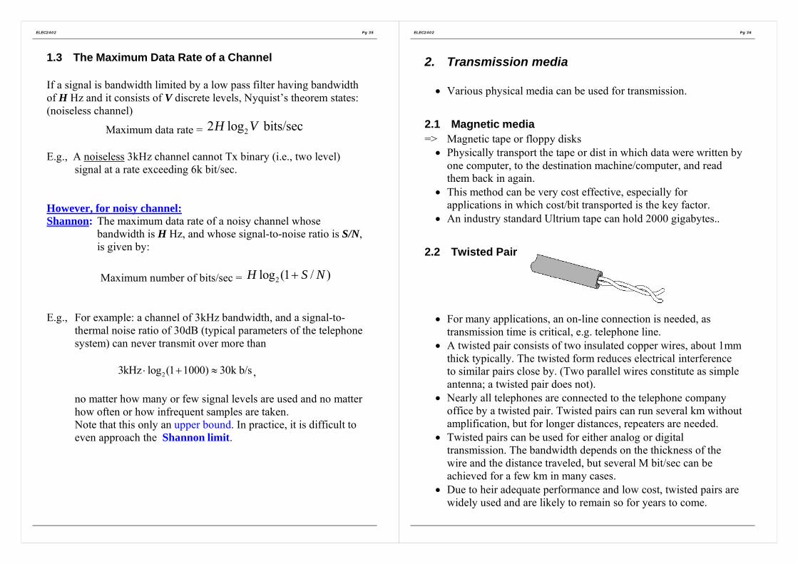
ELEC2402 Pg 35
1.3 The Maximum Data Rate of a Channel
If a signal is bandwidth limited by a low pass filter having bandwidthof H Hz and it consists of V discrete levels, Nyquist’s theorem states:(noiseless channel)
Maximum data rate = 22 log bits/secH V
E.g., A noiseless 3kHz channel cannot Tx binary (i.e., two level)signal at a rate exceeding 6k bit/sec.
However, for noisy channel:Shannon: The maximum data rate of a noisy channel whose
bandwidth is H Hz, and whose signal-to-noise ratio is S/N,is given by:
Maximum number of bits/sec = 2log (1 / )H S N+
E.g., For example: a channel of 3kHz bandwidth, and a signal-to-thermal noise ratio of 30dB (typical parameters of the telephonesystem) can never transmit over more than
23kHz log (1 1000) 30k b/s⋅ + ≈ ,
no matter how many or few signal levels are used and no matterhow often or how infrequent samples are taken.Note that this only an upper bound. In practice, it is difficult toeven approach the Shannon limit.
ELEC2402 Pg 36
2. Transmission media
• Various physical media can be used for transmission.
2.1 Magnetic media=> Magnetic tape or floppy disks
• Physically transport the tape or dist in which data were written byone computer, to the destination machine/computer, and readthem back in again.
• This method can be very cost effective, especially forapplications in which cost/bit transported is the key factor.
• An industry standard Ultrium tape can hold 2000 gigabytes..
2.2 Twisted Pair
• For many applications, an on-line connection is needed, astransmission time is critical, e.g. telephone line.
• A twisted pair consists of two insulated copper wires, about 1mmthick typically. The twisted form reduces electrical interferenceto similar pairs close by. (Two parallel wires constitute as simpleantenna; a twisted pair does not).
• Nearly all telephones are connected to the telephone companyoffice by a twisted pair. Twisted pairs can run several km withoutamplification, but for longer distances, repeaters are needed.
• Twisted pairs can be used for either analog or digitaltransmission. The bandwidth depends on the thickness of thewire and the distance traveled, but several M bit/sec can beachieved for a few km in many cases.
• Due to heir adequate performance and low cost, twisted pairs arewidely used and are likely to remain so for years to come.

ELEC2402 Pg 37
2.3 Coaxial Cable
Two kind of coaxial cable are widely used:(a) 50-ohm cable (used for digital transmission) ;(b) 75-ohm cable (is used for analog transmission).
Figure B-2 A coaxial cable
(a) Baseband: 50-ohm cable (digital transmission)• The construction of the coaxial cable fives it a good combination
of high bandwidth and excellent noise immunity.• The bandwidth possible depends on the cable length. For 1 km
cable, a data rate of 10M b/s is feasible. Higher data rates arepossible on shorter cables.
• Coaxial cables are widely used for local area network and forlong-distance transmission with the telephone system.
(b) Broadband coaxial cable: 75-ohm cable (analog transmission)• It is used for analog transmission on standard cable television.• Modern cables have a bandwidth of close to 1GHz• Broadband systems are normally divided up into multiple
channels frequency the 6MHz channels used for televisionbroadcasting. Each channel can be used for analog television,high-quality audio, or a digital bit stream at, say, 3Mb/s,independent of the other channels. Television and data can bemixed on the same cable.
ELEC2402 Pg 38
2.4 Fiber Optics
• An optical transmission system has three components:(a) the transmission media, (b) the light source (c) the detector
• The transmission medium is an ultra-thin fiber of glass or fused silica.• The light source is either LED (Light Emitting Diode), or a laser diode,
both of which emit light pulses when an electrical current is applied.• The detector is a photodiode, which generates an electrical pulse when
light fall on it.• A light pulse can be used to signal a 1 bit; the absence of a pulse signals a
0 bit.• Fiber optic links are being installed for long-distance telephone lines in
many countries. This trend will continue during the next few decades,with coaxial cable being replaced by firer on more and more routes.
Figure B-3 (a) Three examples of a light ray from inside a silica fiberimpinging on the air/silica boundary at different angles. (b) Light trapped
by total internal reflectionAs shown in Figure B-3, for angles of incidence above a certain critical value,the light is refracted back into the silica; none of it escapes into the air (orreflection). => critical angle.
• However, if the fiber’s diameter is reduced to one wavelength of light,the firer acts like a wave guide, and the light will propagate in a straightline, without bouncing, yielding a single mode fiber.
• Single mode fiber require (expensive) laser diodes to drive them, ratherthan (inexpensive) LEDs, but they are more efficient and can be run forlonger distances.
• Currently available firer optics system can transmit data at 50Gbps for100km without amplification.
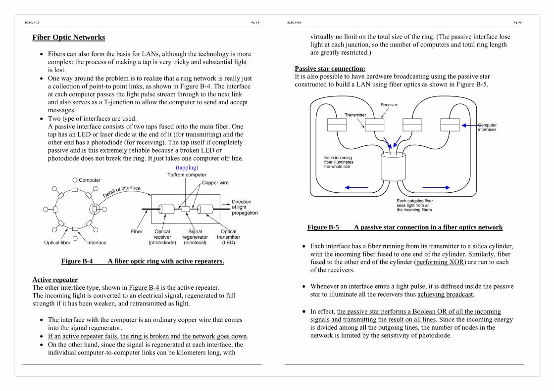
ELEC2402 Pg 39
Fiber Optic Networks
• Fibers can also form the basis for LANs, although the technology is morecomplex; the process of making a tap is very tricky and substantial lightis lost.
• One way around the problem is to realize that a ring network is really justa collection of point-to point links, as shown in Figure B-4. The interfaceat each computer passes the light pulse stream through to the next linkand also serves as a T-junction to allow the computer to send and acceptmessages.
• Two type of interfaces are used:A passive interface consists of two taps fused onto the main fiber. Onetap has an LED or laser diode at the end of it (for transmitting) and theother end has a photodiode (for receiving). The tap itself if completelypassive and is this extremely reliable because a broken LED orphotodiode does not break the ring. It just takes one computer off-line.
Figure B-4 A fiber optic ring with active repeaters.
Active repeaterThe other interface type, shown in Figure B-4 is the active repeater.The incoming light is converted to an electrical signal, regenerated to fullstrength if it has been weaken, and retransmitted as light.
• The interface with the computer is an ordinary copper wire that comesinto the signal regenerator.
• If an active repeater fails, the ring is broken and the network goes down.• On the other hand, since the signal is regenerated at each interface, the
individual computer-to-computer links can be kilometers long, with
(tapping)
ELEC2402 Pg 40
virtually no limit on the total size of the ring. (The passive interface loselight at each junction, so the number of computers and total ring lengthare greatly restricted.)
Passive star connection:It is also possible to have hardware broadcasting using the passive starconstructed to build a LAN using fiber optics as shown in Figure B-5.
Figure B-5 A passive star connection in a fiber optics network
• Each interface has a fiber running from its transmitter to a silica cylinder,with the incoming fiber fused to one end of the cylinder. Similarly, fiberfused to the other end of the cylinder (performing XOR) are run to eachof the receivers.
• Whenever an interface emits a light pulse, it is diffused inside the passivestar to illuminate all the receivers thus achieving broadcast.
• In effect, the passive star performs a Boolean OR of all the incomingsignals and transmitting the result on all lines. Since the incoming energyis divided among all the outgoing lines, the number of nodes in thenetwork is limited by the sensitivity of photodiode.

ELEC2402 Pg 41
2.5 Line of sight transmission (Wireless)• Laser or infrared communication is fully digital, and highly
direction, making it almost immune to tapping or jamming. Onthe other hand, rain and fog may interfere with thecommunication, depending on the wavelength chosen.
• For long distance communication, microwave radio transmissionis widely used as an alternative to coaxial cable.Parabolic antennas can be mounted on towers to send a beam toanother antenna tens of kilometers away. This system is widelyused for both telephone and television transmission.The higher the tower, the greater the range.With a 100 meter high tower, distance of 100km between towersare feasible.The advantage: cheaper than digging a 100km trench, layer
cable or fiber in it.Microwave propagation is affected by thunderstorms and otheratmospheric phenomena.
• Most u-wave transmission occurs at 2GHz to 40GHzcorresponding to wavelength of 15cm to 0.75 cm. Thesefrequencies have been divided into bands of common carrier,government, military and other used.
• Most long distance telephone traffic takes place in the range 4-6GHz although it is increasingly overcrowded.Higher frequencies are available, but they are less useful forlong-distance Tx as the attenuation is greater at higher frequency.
ELEC2402 Pg 42
2.6 Communication Satellites
• A communication satellite can be thought of as a big microwaverepeater in the sky.
• It contains one or more transponders, each of which listens tosome portion of spectrum, amplifies the incoming signal, andthen rebroadcasts it at another frequency, to avoid interferencewith the incoming signal.
• The downward beams can be broad, covering substantial fractionof the earth’s surface; or narrow, covering an area hundreds ofkilometers in diameter.
• At an altitude of ~36,000km above the equator, the satelliteorbital period is 24 hours, so it revolves at the same rate as theearth under it (i.e, Geo-stationary).An observer looking at a satellite in a circular equatorial orbit seethe satellite hand in a fixed spot in the sky, apparently motionless/ stationary.Having the satellite be fixed in the sky is extremely desirable,because otherwise an expensive steerable antenna would beneeded to track it.Communication satellite at lower altitudes (less than 36,000km)are not very useful because they are within sight of the groundsfor only a short time interval.

ELEC2402 Pg 43
3. Data Encoding for transmission
Binary data must be encoded appropriate signals for transmission overthe physical medium. Different signal elements are used to representbinary 1 and binary 0.
3.1 Non-return-to-zero (NRZ)
The simplest encoding scheme is NRZ (non-return-to-zero). Twodifferent voltage levels, one positive and one negative are used assignal elements to represent the two binary digits. The voltagemaintains a constant level during a bit period. The signal voltage levelnever returns to zero. This scheme is also known as NRZ-L (level).
Two schemes of NRZ: High => 0 or Low => 0.
There is a variation of NRZ, called NRZI (non-return-to-zero-inverted). The data are encoded as the presence or absence of a signaltransition at the beginning of a bit time.
Two NRZI schemes: NRZI-0 (transition at 0 only) andNRZI-1 (transition at 1 only).
ELEC2402 Pg 44
NRZI belongs to a type of encoding scheme, called “differentialencoding”. The coding is done by comparing the polarities of theadjacent signal elements.
Advantages of NRZITransition is more immune to noise than level. It also helps tosimplify wiring. e.g. If the twisted-pair cable is used, the leads ofthe two wires can be connected interchangeably.
Disadvantage NRZ-L and NRZIDepending on the bit patterns, there may be a constant voltagelevel over a long period. This may cause the loss ofsynchronization between transmitter and receiver.
3.2 Biphase encoding scheme
In biphase encoding, at least one transition per bit time.
Manchester code is a popular biphase encoding scheme.
There is always a transition in the middle of a bit period.Low-to-high transition => 1High-to-low transition => 0
The presence of at least a transition per clock period=> The receiver can synchronize on that transition=> self-clocking.
There is a variation of Manchester code – Differential Manchester. Inaddition to mid-bit transitions,
Presence of a transition at the beginning of a bit time => 0.Absence of a transition at the beginning of a bit time => 1

ELEC2402 Pg 45
Differential Manchester encoding scheme has a further advantage ofbeing a differential encoding scheme.
The major disadvantage of biphase coding is the higher bandwidthrequirement.
ELEC2402 Pg 46
3.3 Multilevel encoding scheme
In the above discussion, signals are transmitted in the binary form. Insome situations, higher transmission rate with restricted bandwidth isrequired. Can use multilevel encoding scheme. e.g. can use a 4-levelsystem to transmit a signal element (which contains 2 bits) per signalinterval.Bit rate = no. of bits transmitted per secondBaud rate = no. of signal elements per secondFor binary system, bit rate = baud rate.For a multilevel system, baud rate is generally less than the bit rate.e.g. the following diagram shows an example of a 4-level system witha baud rate which is 1/2 of the bit rate.

ELEC2402 Pg 47
4. Asynchronous and Synchronous Transmission
Reception of digital data involves sampling the incoming signal onceper bit time to determine the binary value. One of the difficultiesencountered in such a process is that various transmissionimpairments will corrupt the signal so that occasional errors will occur.This problem is compounded buy a timing difficulty. In order for thereceiver to sample the incoming bits properly, it must know the arrivaltime and duration of each bit that it receives.
There are two approaches for achieving the desired synchronization:i) Asynchronous Transmission (as used in most of the personal
computer Modem).ii) Synchronous Transmission.
ELEC2402 Pg 48
4.1 Asynchronous Transmission
This scheme is to avoid the timing problem by not sending long,uninterrupted streams of bits. Instead, (the RS232,for example) dataare transmitted one character at a time, where each character is five toeight bits in length. Timing or synchronization must only bemaintained within each character; the receiver has the opportunity tore-synchronize at the beginning of each new character.
Figure B-6 illustrates this technique. When no character is beingtransmitted, the line between transmitter and receiver is in an idle state.The definition of idle is equivalent to the signaling element for binary1. the beginning of a character is signaled by a start bit with a value ofbinary 0. This is followed by five to eight bits that actually make upthe character. The bits of the character are transmitted beginning withthe least significant bit. The parity bit is set by the transmitter suchthat the total number of ones in the character, including the parity bit,is even (even parity) or odd (odd parity), depending on the conventionbeing used.

ELEC2402 Pg 49
Figure B-6 Asynchronronous Transmission.
ELEC2402 Pg 50
4.2 Synchronous Transmission
With synchronous transmission, a block of bits is transmitted in asteady stream without start and stop codes. The block may be manybits in length. To prevent timing drift between transmitter and receiver,their clocks must somehow be synchronized. One possibility is toprovide a separate clock line between transmitter and receiver. Oneside (transmitter or receiver) pulses the line regularly with one shortpulse per bit time. The other side uses these regular pulses as a clock.The other alternative is to embed the clocking information in the datasignal such as Manchester or differential Manchester encoding fordigital signal and carrier frequency for analog signals.

ELEC2402 Pg 51
Modem e.g., computerModeme.g., computer
ModemModem
5. RS232-C
A standard serial interface adopted by the EIA. It specifies the (a)electrical (V.28), (b) mechanical (ISO2110), (c) functional (V.24) and(d) procedural (V.24) specifications of the interface between DTE andDCE.
• DTE – Data Terminal Equipment (e.g., computer)User (Subscriber) side of the User/Network Interface (e.g.computer, front-end processor, intelligent terminal)
• DCE – Data Circuit Termination Equipment (e.g., modem)Network side of the User/Network interface (i.e., entry/exit pointof the network)Can be a modem or node processor.Sometimes called Interface Message Processor (IMP-Arpanet)V.24 is the international version of RS-232.
Figure B-7 Data communications interfacing
ELEC2402 Pg 52
5.1 RS-232C: Mechanical Specification (ISO 2110)Specifies the precise form of physical connections between DTE &DCE 25-pin connector.
Figure B-8 Pin Assignments for V.24/EIA-232 (DTE Connector Face – Male)
In most applications, only a sub-set of pins is used.e.g., the 9-pin DB-9 connector used in PC.
Figure B-9 DB-9 Male Connector for RS232

ELEC2402 Pg 53
5.2 RS-232C: Electrical Specification (V.28)
The V.28 describes the electrical characteristics of signal at each pin(interchange circuit). e.g. voltage level and timing of voltage changes.Unbalanced: all circuits share a common ground
Bipolar-voltageON (Logic 0) +3 to +15 volt dcOFF (Logic 1) -3 to -15 volt dc
No damage if signal lines shorted to ground or each other.Driver skew rate (i.e., dv/dt) < 30V/µs.
It supports binary data transmission up to 20 kbps.
Cable is limited to 50 feet at 20 kbps. Longer length and higher ratenot defined. Provides guidelines for 64 kbps.
5.3 RS-232C: Functional Specification (V.24)The V.24 describes the functional specification. Assign meaning toeach interchange circuit.Simplex exchange of data in one direction onlyHalf-duplex in either direction but not simultaneouslyFull-duplex in both directions at the same time
RS-232-C supports all the above modes of transmission by providingseparate TX Data and RX Data interchange circuits.
It also supports asynchronous/synchronous transmissions by providingclock signals between DTE and DCE.
Interchange circuits can be classified into 4 groups: data, control,timing and ground as shown in the following table.(Only 9 pins are commonly used.)
ELEC2402 Pg 54
Some commonly used RS-232C signals:
There is also a secondary channel.

ELEC2402 Pg 55
5.4 RS-232C: Procedural Specification (V.24)
The V.24 describes the procedural specification. Specifies thesequence of interchange circuit activities for a particular application.
Widely used and mis-used• Longer cable and higher rate• Connecting serial I/O device to PC. In this case, which one is
the DTE and which one is the DCE?
ELEC2402 Pg 56
The following diagram show a typical Dial-Up operation using theRS-232-C.

ELEC2402 Pg 57
6. RS-499
Intend to gracefully retire the RS-232.(For PC, it seems loosing the battle to the USB, dated year 2003.)
Specifying the mechanical, electrical, functional and proceduralinterfaces between DTE and DCE.Supports asynchronous/synchronous serial, binary data transmissionfull/half duplex
Two modes of transmission:RS-423-A
Similar to RS-232-C, unbalanced, up to 20 kbps bipolar-voltageTX and RX.
RS-422-ABalanced mode, up to 2 Mbps.Cable limited to 200 feet at 2 MbpsLonger length at lower rate are possible but not defined.ON (Binary 0) +200 mV to +6V dcOFF (Binary 1) -200 mV to -6V dc
37-pin connector with 35 signal lines assigned and 9-pin secondaryconnector with 9 signal lines assigned.
ELEC2402 Pg 58
i.e., 4 wires instead of 2.
Balanced-Line TX System (e.g., for the RS-422)
Differential techniques.
Two lines are used to transmit one signal instead of one.Noise appears common-mode at the receiver input terminals, where itis rejected.For high speed operation, reflection is virtually eliminated whenterminated lines are used.Line-termination resistors (Rt) are required only at extreme ends ofthe line. For short lines, termination resistors at the RX ends only mayprove adequate.

ELEC2402 Pg 59
7. Analog TransmissionFor the past 100 year, analog transmission dominated.
7.1 The telephone system
Design aim: transmitting human voice in a more or lessrecognizable form. Not up to the requirements forcomputer communication.
Telephone line: max. data rate 56kbps.There are more than 300 million telephone in the world.
Their inter-connection can be in various forms:
Figure B-10. (a) Fully-interconnected network. (b) Centralized switch. (c)Two-level hierarchy
Figure B-11 A typical circuit route for a medium-distance call.
|<~ 1 – 10 km>|
or local central office
ELEC2402 Pg 60
7.2 Modems
• For telephone system, the signals (baseband) are band limited to300Hz to 3kHz by filters, which is not suitable for high speedand long distance. – i.e., bandwidth limited and attenuation.
Without the filter, a pair of copper wires could carry traffic at 1or 2 M b/s without any trouble.Thus modulation techniques are introduced: AM and AngleModulation.
• The Modem (modulator-demodulator) is inserted between the(digital) computer and the (analog) telephone system. TheModem accepts a serial stream of bits and produces a modulatedcarrier as output (or vice versa).
• Cable TV (typically 6MHz bandwidth) is also a form for localdistribution. Most cable systems offer many channels (typically300MHz bandwidth) and can be used as a data transmissionfacility. Unlike the local loops of the telephone system, cable TVdoes not use a star pattern radiating out from an end office,instead, everyone in the same neighborhood shares the samecable.

ELEC2402 Pg 61
AM, or On-Off Keying (OOK).
message
FM, or Frequency Shift Keying (FSK).
PM, or Phase Shift Keying (FSK).
Figure B-12 (a) A binary signal. (b) Amplitude modulation. (c)Frequency modulation. (d) Phase modulation.
ELEC2402 Pg 62
Figure B-13 (a) QPSK. (b) QAM-16. (c) QAM-64.
Figure B-14. (b) The “V.32” for 9600 bps, (c) The “V.32 bis” for 14,000bps.
The International Telegraphic Union (ITU) defines the standards. TheV.xx is the specification number. The term ‘bis’ refers to 2nd version.

ELEC2402 Pg 63
V.90 (modem)
V.90 is a standard approved in 1998 in response to the need anddemand of fast interconnection between users and Internet ServiceProviders (ISPs).Conventionally, when a Data Terminal Equipment (DTE)communicates with another DTE through the public switchedtelephone network (PSTN), there is a series of signal conversion.
This arrangement is necessary because the subscriber loops are stilllargely analog even if the network is digital. On the network side, acodec (coder-decoder) converts the analog signal into digital form.The analog-to-digital conversion introduces quantization error, amajor limiting factor on speed. The converted digital travels throughthe network to the destination end which has a codec to convert thedigital signal to analog form before sending it down the subscriberloop.
Figure B-15. The use of both analog and digital transmission for acomputer to computer call. Conversion is done by the modem and codecs.
DTE = Data Terminal Equipment (e.g., computer)DCE = Data Circuit Equipment (e.g., modem)
ModemModem
ELEC2402 Pg 64
This series of conversions together with the signal-to-noise ratio oftelephone lines limits the transmission speed to 33.6 kbps with V.34.Connecting a computer to an ISP is a very popular usage of the PSTNnowadays.
Downstream From ISP to userUpstream From user to ISP
An ISP may subscribe to a digital loop with the network. The use of adigital modem bypasses the codec. The subscriber loop at the user’sside is still analog.
Figure B-16. The use of digital transceiver at ISP side bypasses the codec.
Downstream direction:The analog modem of the user converts the analog signal intodigital signal. However, the quantization error at this last stage isvery low. The analog modem is designed to convert analog signalwhich was originally in digital form.V.90 uses 7 bits per sample at 8 kbps, yielding 56 kbps. Howeverthe rulings from Federal Communications Commission (FCC)further restrict the transmission speed to 54 kbps.

ELEC2402 Pg 65
Upstream direction:The codec at the network is designed to digitize analog signal(voice) which may not be originally digital. Although there is andigital network access at the ISP end, the quantization errorsintroduced at the user end is the dominating factor. This limitsthe upstream speed to 33.6 kbps.
Speed of data transfer in V.90 is thus asymmetrical.
Downstream: Up to 56 kbps;Up to 54 kbps in compliance with FCC,
Upstream: Up to 33.6 kbps.
(Note: The actual speed depends on the line conditions.)
ELEC2402 Pg 66
Asymmetric Digital Subscriber Line (ADSL)
Problems that a telco (telephone company) has to face:Demand for multi-media and Internet services;=> require high speed communication between server and the
subscriber.
Existing subscriber loop is largely analog.Rewiring = > time and cost.
But need to capture the market now by using as far as possible theexisting twisted pair copper in Plain Old Telephone Service (POTS).
ADSL is a new modem technology that telcos can use to turn theexiting twist pair subscriber loops into high-speed datacommunication links.
Figure B-17. A typical ADSL connection.
Upstream (16 – 640 kb/s)
Downstream (1.5 - 8 Mb/s)

ELEC2402 Pg 67
Use advanced digital signal processing (DSP) technologies.
ADSL is a passband system which generate two or more channelsover the baseband. Thus the 0-4 kHz bandwidth is reserved for voicecommunication while higher frequency channels are for data.
Therefore, the ADSL modem operates simultaneously with regulartelephone service. Each subscriber uses his own existing twisted paircopper as the ADSL access link. Therefore, throughput is not affectedby the other users in his neighborhood.
Figure B-18 A typical ADSL equipment configuration.
Digital Subscriber Line Access Multiplexer = (DSLAM)
ELEC2402 Pg 68
ADSL modem use FDM to create channels for upstream anddownstream traffic. There are two common schemes:
(a) CAP (Carrier-less Amplitude and Phase Modulation)(b) DMT (Discrete Multitone modulation)
(a): CAP (Carrier-less Amplitude and Phase Modulation)While the name specifies that the modulation is "carrierless",an actual carrier is imposed by the transmit band shapingfilter through which the outbound symbols are filtered.Hence CAP is algorithmically identical to QAM. Comparedto DMT it is slightly inferior and DMT is now the officialANSI, ETSI and ITU-T standard for ADSL.
Figure B-19Operation of ADSL using Carrier-less Amplitude and Phase Modulation.
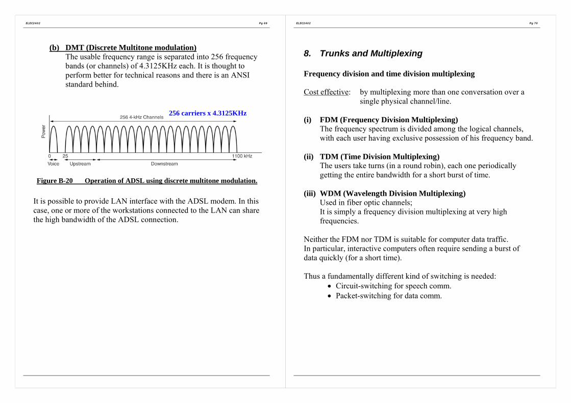
ELEC2402 Pg 69
(b) DMT (Discrete Multitone modulation)The usable frequency range is separated into 256 frequencybands (or channels) of 4.3125KHz each. It is thought toperform better for technical reasons and there is an ANSIstandard behind.
Figure B-20 Operation of ADSL using discrete multitone modulation.
It is possible to provide LAN interface with the ADSL modem. In thiscase, one or more of the workstations connected to the LAN can sharethe high bandwidth of the ADSL connection.
256 carriers x 4.3125KHz
ELEC2402 Pg 70
8. Trunks and Multiplexing
Frequency division and time division multiplexing
Cost effective: by multiplexing more than one conversation over asingle physical channel/line.
(i) FDM (Frequency Division Multiplexing)The frequency spectrum is divided among the logical channels,with each user having exclusive possession of his frequency band.
(ii) TDM (Time Division Multiplexing)The users take turns (in a round robin), each one periodicallygetting the entire bandwidth for a short burst of time.
(iii) WDM (Wavelength Division Multiplexing)Used in fiber optic channels;It is simply a frequency division multiplexing at very highfrequencies.
Neither the FDM nor TDM is suitable for computer data traffic.In particular, interactive computers often require sending a burst ofdata quickly (for a short time).
Thus a fundamentally different kind of switching is needed:• Circuit-switching for speech comm.• Packet-switching for data comm.

ELEC2402 Pg 71
Figure B-21 Frequency-division multiplexing. (a) The originalbandwidths. (b) The bandwidths raised in frequency. (c) The multiplexed
channel.
ELEC2402 Pg 72
9. Circuit switching
Occupies a dedicated end-to-end channel or connection once a call has been setup and continue to occupy until the called is finished. E.g., the telephoneswitching system.
It requires to set up an end-to-end path before any data can be sent.A typical call set-up time for the telephone system is about 10 seconds, andwould be longer for long-distance or international calls.During this time interval, the telephone system is hunting for (establishing) anend-to-end connection or path through the network.
Once the setup has been completed, the only delay for data or speech is mainlythe propagation time for the electromagnetic signal, about 6msec/1000km.Thus no traffic congestion since a dedicated path has been established.
Circuit switching: a physical connection is reserved all the way from end toend throughout the duration of the call.
Figure B-22 (a) Circuit switching. (b) Packet switching.
- - - circuit connection
Stored &Forward

ELEC2402 Pg 73
Figure B-23 Timing of events in (a) circuit switching. (b) messageswitching. (c) packet switching.
ELEC2402 Pg 74
10. Packet Switching• No dedicated channel is established in advance between sender
and receiver.• When the sender has a block of data to be sent, it is stored in the
first switching office (i.e., IP or node), and then forwarded (afterinspection) later, one hop at a time.Each block is received in its entirety, inspected for error andretransmitted. A network using this technique is called a store-and-forward network.
Message switching• There is no limit on block size as the entire message is being
sent at a time.• Disadvantage: This means the IMPs or nodes must have a large
memory space to buffer long blocks; which may also tie up anIMP-IMP line for many minutes, and also suffer from long end-to end delay.For these reason, message-switching technique is never used forcomputer network
Packet switching• It place a tight upper limit on block size, allowing packets to be
buffered in IMP main memory instead of on disk that is usuallyrequired for message switching.
• By making sure that no user can monopolize any transmissionline for more than a few tens of milli-seconds, packet switchingnetworks are well suited to handling interactive traffic.
• Due to smaller block size as shown Figure B-23; the first packetof a multi-packet message can be forwarded before the secondone has fully arrived, thus reducing delay and improvingthroughput.However, smaller packet size would increase overhead due tothe packet header for control information -> trade off betweenefficiency and delay ---> optimal packet length? (~ a few msec.Of voice data packet).

ELEC2402 Pg 75
Differences between circuit switching & packet switching
Item Circuitswitched
Packet switched
Call setup Required Not needed
Dedicated physical path Yes No
Each packet follows the sameroute
Yes No
Packets arrive in order Yes No
Is a switch crash fatal Yes No
Bandwidth available Fixed Dynamic
Time of possible congestion At setup time On every packet
Potentially wasted bandwidth Yes No
Store-and-forward transmission No Yes
Transparency Yes No
Charging Per minute Per packet
ELEC2402 Pg 76
Section C
The Data Link Layer (Layer 2)
1. Data link layer design issues
2. Error detection and correction
3. Elementary Data link protocols
4. Sliding Window Protocols
5. Protocol performance
6. Example Data link protocols

ELEC2402 Pg 77
1. Data link layer design issues
• The data link layer is the layer 2 of the OSI model.• The data link layer deals with the algorithms for achieving
reliable, efficient communication between two adjacent machinesat the data link layerThe term “adjacent” mean that the two machines are physicallyconnected by a communication channel (in this case the physicallayer – it delivers bits in exactly the same order in which the bitsare sent.)
• The data link layer has to work with the following constraints orlimitation:
(i) Non-error-free bit streams from physical later;(ii) finite data rate;(iii) non-zero propagation delay between the time a bit is
sent and the time it is received;(iv) finite processing speed of the machines
The data link layer has a number of specific functions to carry out:• Provide a well defined service interface to the network layer
• Determine how the bits of the physical layer are grouped intoframes
• Deal with transmission error
• Regulate the flow of the frames so that slow receivers are notswamped by fast senders
• General link management
ELEC2402 Pg 78
1.2 Services provided to the network layer
• The function of the data link layer is to provide services to thenetwork layer (3).
Figure C-1 (a) Virtual communication. (b) Actual communication.
• The principle service is transferring data from the network layeron the source machine to the network layer on the destinationmachine.
• On the source machine there is an entity, call it a process, in thenetwork layer that hands some bits to the data link frotransmission to the destination.
• The job of the data link layer is to transmit the bits to thedestination machine, so they can be handed over to the networklayer on the destination machine, as shown in Figure C-1.
• However the actual transmission follows the path of Figure C-1,but it is way to think in term of two data link layer processescommunicating using a data link protocol
• For this reason, we will implicitly use the model of Figure C-1throughout the notes; unless specified otherwise.

ELEC2402 Pg 79
The data link layer can be designed to offer various services. Theactual services offered can vary from system to system.
Three reasonable possibilities services are:(a) Unacknowledged connectionless service(b) Acknowledged connectionless service.(c) Connection-oriented service.
(a) Unacknowledged Connectionless service• The source machine send independent frames (e.g. packets) to
the destination machine without having the destination machineacknowledge them.
• No connection is established beforehand or released afterwards• If a frame is lost due to noise on the line, no attempt is made to
recover in the data link layer.• This class of service is appropriate
i. When the error rate (e.g. BER) is very low and recovery isleft to higher layers.
ii. For real time traffic, such as speech, in which late data areworse than bad data.
• Many LANs have unacknowledged connectionless service in thedata link layer.
ELEC2402 Pg 80
(b) Acknowledged connectionless service• No connection used, but each frame sent is individually
acknowledged.Thus, the sender knows whether or not a frame has arrived safely.If it has not arrived within a specified time interval (i.e., timestamp), it can be sent again.
(c) Connection-oriented service• With this sophisticated service, the source and destination
machines establish a connection before any data are transferred.(virtual circuit switching).
• Each frame sent over the connection is numbered, and the datalink layer guarantees that each frame sent is indeed received.
• It also guarantees that each frame is received once only and allframes are received in the right order.
• The transfers have three distinct phases:1st phase – the connection is established by having both sides
initialize variables and counters needed to keep trackof which frames have been received and which oneshave not.
2nd phase – one or more frames are actually transmitted.3rd phase – the connection is released, freeing up the variables,
buffers, and other resources used to maintain theconnection.

ELEC2402 Pg 81
1.3 Framing
• In order to provide service to the network layer, the data linklayer must use the service provided to it by the physical layer.
• The bit stream provided by the physical layer is not guaranteed tobe error free. The number of bits received may less than, equal to,or more than the number bits transmitted, and they have differentvalues.
• It is up to the data link layer to detect, and if necessary, correcterrors.
• The data link layer usually breaks the bit stream up into discreteframes and compute the checksum for each frame, (using achecksum algorithm).
• When a frame arrives at the destination, the checksum isrecomputed.
• If the newly computed checksum is different from the onecontained in the frame, the data link layer knows that an error hasoccurred and takes steps to deal with it (e.g., discarding the badframe and sending back an error report).
Breaking the bit stream up into frames is more difficult than it at firstappears. The following four framing methods are commonly used:
(a) Character count(b) Starting and ending characters, with character stuffing(c) Starting the ending flags, with bit stuffing(d) Physical layer coding violations
ELEC2402 Pg 82
(a) Character count (rarely used)• The first framing method uses a field in the header to specify the
number of characters in the frame, as shown in Figure C-2.
Figure C-2 A character stream. (a) Without errors. (b) With one error.
• The drawback of this algorithm is that the count can be garbledby a transmission error. e.g., Figure C-2 shows that if thecharacter count of 5 in the second frame becomes a 7, thedestination will get out of synchronization and will be unable tolocate the start of the next frame. i.e., all the subsequent framesare out of synchronization and frame resynchronization after anerror is usually not possible. Therefore, the character countframing method is rarely used anymore.

ELEC2402 Pg 83
(b) Starting and ending characters, with character stuffing• The second framing method gets around the problem of
resynchronization after an error by having each frame start andend with special bytes. In the past, the starting and ending byteswere different, but in recent years most protocols have used thesame bytes, called a flag byte, as both the starting and endingdelimiter, as shown in Figure C-3 as FLAG.
Figure C-3 (a) A frame delimited by flag bytes. (b) Four examples ofbyte sequences before and after byte stuffing.
• A problem occurs when the flag byte’s bit pattern occurs in thebinary data of the framing. One way to solve this problem is touse character stuffing, as shown in Figure C-3.
• Character stuffing = The sender’s data link layer insert an ESCcharacter just before each “accidental” flag byte in the data. Thedata link layer on the receiver end removes the ESC byte beforethe data are given to the network layer.
• A major disadvantage is the method is closely tied to 8-bitcharacter, particularly ASCII code. As networks develop, newand efficient techniques were developed.
ELEC2402 Pg 84
(c) Starting and ending flags, with bit stuffing• The third, framing method allows data frames to contain an
arbitrary number of bits, and allows character codes with anarbitrary number of bits per character.
• It works like this. Each frame begins and ends with a special bitpattern, namely 0111 1110. Whenever the sender’s data linklayer encounters 5 consecutive ones in the data, is automaticallystuffs a 0 bit into the outgoing bit stream. (e.g., data 01111110 istransmitted as 011111010).
Figure C-4 Bit stuffing. (a) The original data. (b) The data as theyappear on the line. (c) The data as they are stored in the receiver’s
memory after destuffing.
• Thus, when the receiver see 5 consecutive incoming 1 bits,followed by a 0 bit, it automatically destuffs (i.e., delete) the 0 bit
• Just as the character stuffing is completely transparent to thenetwork layer in both computers, so is bit stuffing.
• With bit stuffing, the boundary between two frames can beunambiguously recognized by the flag pattern, 0111 1110. Thusif the receiver loses track of where it is, all it has to do is to scanthe input for flag sequences, since they can only occur at frameboundaries and never within the data.
Data

ELEC2402 Pg 85
(d) Physical layer coding violations
• The fourth-framing method is only applicable to networks inwhich the encoding on the physical medium contains someredundancy.e.g. Manchester coding: it encoded each 1 bit as a high-low pair
and it encodes each 0 bit as a low-high pair.The combinations high-high and low-low are not used fordata.Some protocols use an invalid sequence such as high-high-low-low framing.
• It has the clear advantage that no stuffing is required.
• This use of invalid physical code is part of the IEEE 802 standard.
In fact, many data link protocols use a combination of a charactercount with one of the other methods for extra safety.
Only if the appropriate delimiter is present at that position and thechecksum is correct, is the frame accepted as valid;otherwise, the input stream is scanned for the next delimiter.
ELEC2402 Pg 86
1.4 Error control• Having solved the problem of framing, we next consider how to
make sure all frames are eventually delivered to the networklayer at the destination, and in proper order.
• Two techniques are commonly used:i. Acknowledgement;
ii. Timer and frame sequence numbering.
(i) Acknowledgement• Typically the protocol calls for the receiver to send back special
control frames bearing positive or negative acknowledgementsabout the incoming frames.
• If the sender receives a positive acknowledgement about a frame,everything is fine (it knows the frame has arrived safely).
• On the other hand, a negative acknowledgement means thatsomething has gone wrong, and the frame must be transmittedgain (retransmission).
(ii) Timers and frame sequence numbering• Timer is used to overcome the problem of frame lost.
i.e., Faulty hardware may cause a frame to vanish completely (e.g.in a noise burst); and the sender having transmitted a framewould then waits for acknowledgement, and hence it would hangforever as the receive had not received anything and noacknowledgement would be sent.
• This problem can be solved by introducing timers into the datalink layer and they work as follows:When the sender transmits a frame, it generally also starts a timer.The timer is set to go off after an interval long enough for theframe to reach the destination, be processed there, and have theacknowledgement propagate back to the sender. Normally theframe will be correctly received and the acknowledgement will

ELEC2402 Pg 87
get back before the timer runs out, in which case it will becancelled.
• Frame sequence numbering:If, either the frame or the acknowledgement is lost, the timer willgo off, alerting the sender a potential problem, and hence causinga retransmission.
However, when frames may be transmitted multiple times, thereis a danger that the receiver will accept the same frame two ormore times, and pass it to the network layer more than once.To prevent this from happening, it is necessary to assignsequence numbers to outgoing frames, so that the receiver candistinguish retransmissions from originals.
The whole issue of managing the timers and sequence numbersso as to ensure that each frame is ultimately passed to thenetwork layer at the destination exactly once, no more and noless, is an important part of the data link layer’s duties.
ELEC2402 Pg 88
1.5 Flow Control• Another important design issue that occurs in the datalink layer
(and higher layers as well) is what to do with a sender thatsystematically wants to transmit frames faster than the receivercan accept them
• This situation can easily occur when the sender is running on afast (or lightly load) computer and the receiver is running on aslow (or heavily loaded) machine.So at a certain point, the receiver will simply not be able tohandle the frames as they arrive, and will start to lose data.
• The usual solution is to introduce flow control to throttle thesender into sending no faster than the receiver can handle thetraffic.This throttling generally requires some kind of feedbackmechanism, so the sender can be made aware of whether or notthe receiver is able to keep up.
• Various flow control scheme are known, but most of them usethe same basic principle.The protocol contains well-defined rules about when a sendermay transmit the next frame.These rules generally prohibit frames from being sent until thereceiver has granted permission, either implicitly or explicitly.e.g. when a connection is setup, the receiver might say: “You
may send me n frames now, but after they have been sent,do not send any more until I have told you to continue.”
• We will study various flow control mechanisms in the followingseveral sections.

ELEC2402 Pg 89
1.6 Link management• Another function of the data link layer is to manage the
administration of the link.• With connectionless service, the administration is minimal, but
with connection-oriented service it is more complex.i.e., connections must be established and released, sequence
numbers must be initialized and possibly reinitialized in theface of errors, and so on.
• Furthermore, the configuration of the link must be managed. Inthe simplest case, a physical wire just runs between twomachines. However, it is commonplace that several machinesshare the same channel. Traditionally, one of these is the primary(e.g. a computer) and the others are secondary (e.g., dumbterminals).
• Traffic management is done by having the primary send a shortframe, called a poll to the first secondary, asking if it has anydata to send. If so, the terminal sends the data; otherwise theprimary polls the next secondary.
• In other systems, the terminals are allowed to send data to thecomputer even in the absence of a poll.
• Finally, in still other systems, such as LANs, there are noprimaries and secondary. All stations are equal and have thesame access rights to the channel. In any event, the whole issueof primary and secondary vs. peers is an issue that occurs in thedata link layer.
ELEC2402 Pg 90
2. Error detection and correction
• Transmissions on physical lines are subjected to error – fact oflife.
• Transmission errors on physical lines are caused by a variety ofdifferent physical phenomena, depending on the transmissionmedia and operating environment.
Source of noise {noise = any unwanted signals}• Thermal noise:
It is inevitable that the electrons in the copper wires are buzzingaround at high speed and in all directions, producing a broad-spectrum background noise level.
• Impulse noiseCaused by the arcing of relays, and etc.These pulses or spikes on the line typically have duration of 10msec.
• Amplitude & frequency distortion due to the physical channele.g. twisted –pair, microwave, fiber optics and so on, have theirown and different frequency response.
• CrosstalkIt can occur between two wires that are physically adjacent. Also,for example, microwave links are subject to fading, off-coursebirds and airplanes, etc.
• On PCM trunks, errors are introduced whenever the receiver getsout of sync with the transmitter.

ELEC2402 Pg 91
Burst error• As a result of the physical processes causing the noise, errors
tend to come in bursts rather than singly.
Advantage: When a burst error occurs, only a few blocks or framesare affected; compared to many affected blocks if theerrors are independent rather than in bust. {i.e. less blockerror rate}
Disadvantage: Much harder to detect and correct than that of isolatederrors, and they are harder to model analytically.
Note that the BER for isolated errors and burst errors have differenteffects subjectively and objectively.e.g., subjective effect: perception of human speech
objective effect: less block error rate and harder to detect, asdiscussed above.
ELEC2402 Pg 92
2.1 Error Correcting codes
• Error-Correcting codesTo include enough redundant information along with each blockof data sent to enable the receiver to deduce what the transmittedcharacter must have been.
• Error-detecting codesTo include enough redundancy to allow the receiver to deducethat an error occurred, but not which error. (Then it may request aretransmission).
Message data: m bits 2m possibilities
one-to-one ↓ mapping to
Encoded codeword:n = m + r bits 2m correspondent outr = redundant or of 2n possibilities
check bits.
Hamming distance = the number of bit positions in which twocode words differ.e.g., 11001101
11011001X X
∴ Hamming distance = 2.
Notice that there are 2m possible data messages and not all of the2n possible codewords are used. Using an encoding algorithm forcomputing the r check bits in order to construct a complete list ofthe corresponding codewords, the Hamming distance of thecomplete code is obtained by evaluating the two codewordswhose Hamming distance is minimum from the complete list ofcodewords.

ELEC2402 Pg 93
• The error-detecting and error-correcting properties of a completeset of code depends on its Hamming distance.
To detect d errors, a distance of d+1 code is needed. Becausethere is no way that d single-bit errors can change a validcodeword into another valid codeword. When the receiver seesan invalid codeword, it can tell that a transmission error hasoccurred.
To correct d errors, a distance of 2d+1 code is needed. Becausethat way the legal codewords are so far apart that even with dchanges, the original codeword is still closer than any othercodeword, so it can be uniquely determined.
ELEC2402 Pg 94
Examples(a) Error-detecting code:
Consider a code in which a single parity bit is appended to thedata.The parity bit is chosen so that the number of 1 bits in thecodeword s even (even parity) or odd (odd parity). Such a codehas a distance of 2, since any single-bi error produces a wordwith the wrong parity.i.e., it can only be used to detect single errors.
(b) Error-correcting code:Consider a code with only four valid codewords:This code has a distance of 5, it can correct double errors.
00000 00000This code has a distance of 5,
00000 11111it can correct double errors
11111 0000011111 11111
⎫⎪⎪⎬⎪⎪⎭
If the codeword 00000 00111 arrives, the receiver knows that theoriginal must have been 00000 11111.However, if a triple error changes 00000 00000
into 00000 00111the error will not be corrected properly.
(i.e., it will rather improperly corrected into 00000 11111 as it isclosest to a valid legal wordword.)

ELEC2402 Pg 95
Figure C-5 Use of a Hamming code to correct burst errors.
ELEC2402 Pg 96
2.2 Error detecting codes
• Error-correction codes are sometimes used for data transmission;e.g., when the channel is simplex, so retransmission cannot be
requested.• Error-detecting code are used for data transmission as
retransmission is preferred because it is more efficient.• If a single parity bit is added to a data block, and the block is
badly garbled by a long burst error, the probability that the errorwill be detected is only 0.5 which is unacceptable.This can be improved by the following method:
← ···n bits···· →↑
k bits
↓
( n x k )
datablock
xx::x
x x ……. x x x=parity bits
This method can detect a single burst error of length n, since only1 bit per column will be changed. A burst of length n+1 will passundetected.
• Another method is in widespread use:the polynomial code (also known as cyclic redundancy code orCRC code).

ELEC2402 Pg 97
Polynomial code (Cyclic Redundancy Code or CRC code)• Polynomial codes are based upon treating bit strings as
representations of polynomials with coefficients of 0 and 1 only.e.g. codeword 110 001 can be represented by
polynomial 5 4 3 2 1 01 1 0 0 0 1x x x x x x+ + + + +5 4 1x x= + +
• The basic idea of the polynomial code method is to append achecksum (the remainder in this case) to the end of the dataframe in such a way that the polynomial represented by thechecksum frame is divisible by G(x). {also refer to Figure C-6}
When the receiver gets the checksum frame, it tries dividing it byG(x). If there is a remainder, there has been a transmission error.
Where G(x) = generator polynomial(the sender and receiver must agree upon the same G(x)in advanced)
ELEC2402 Pg 98
Figure C-6 Calculation of the polynomial code checksum.
Note: Subtraction is implemented by XOR.
Append to the message
message
Append 0000to the message

ELEC2402 Pg 99
The algorithm for computing the checksum is as follows: {also referto Figure C-6}
(i) Let r be the degree of G(x). Append r zero bits to the low-order end of the data frame, so it now contains m+r bits, andcorrespond to the polynomial ( )rx m x .where m(x) = message polynomial of m bits.
(ii) Divide the bit string corresponding to ( )rx m x by the bit stringcorresponding to G(x) using mod-2 division, (i.e., uses binaryaddition and subtraction with no carries, which is just theeXclusive-OR (XOR) operation).
(iii)Subtract the remainder (which is always r or fewer bits) fromthe bit string corresponding to ( )rx m x using modulo 2subtraction. (This is equivalent to appending the remainder tothe end of the original data message). The result is thechecksum frame to be transmitted called its polynomial T(x).
For example: (In the base 10 system)19
10941 21027810941100868984692399
Then by subtracting the remainder 2399 off from 210278:
210278- 2399207879
Equal to 207879 is divisible by 10941And 207879 is to be transmitted.
ELEC2402 Pg 100
Implementation of a hardware circuit for calculation of CRC
The CRC process can be represented by a dividing circuit consistingof XOR gates and a shift register. The shift register is a string of 1-bitstorage devices.
The circuit is implemented as follows:1. The register contains n-k bits, equal to the length of the FCS.2. There are up to n-k XOR gates.3. The presence or absence of a gate corresponds to the presence
or absence of a term in the divisor polynomial, P(X), excludingthe terms 1 and Xn-k.
The architecture of a CRC circuit is explained by first considering anexample, which is illustrated in
Figure C-7. In this example, the follow is used:Data D = 1010001101; D(X) = X9 + X7 + X3 + X2 + 1Divisor P = 110101; P(X) = X5 + X4 + X2 + 1 = G(x), say.
As shown in Figure C-7(a) the CRC generating process begins withthe shift register cleared (all zeros). The message, or dividend, is thenentered, one bit at a time, starting with the most significant bit.

ELEC2402 Pg 101
+
+
+
++
+
+
+
Figure C-7 Circuit with Shift Registers for Dividing by the PolynomialX5+X4+X2+1
At the receiver, the same logic is used. As each bit of M arrives, it isinserted into the shift register. If there have been no errors, the shiftregister should contain bit pattern for R (the FCS) at the conclusion ofM. The transmitted bits of R now begin to arrive, and the effect is tozero out the register so that, at the conclusion of reception, the registercontains all 0s.
X4 X2
ELEC2402 Pg 102
Now, let’s consider the power of this method: what kinds of errorwill be detected?
• Imagine that a transmission error occurs, the received polynomialbecomes ( ( ) ( ))T x E x+ instead of ( )T x only.
• The receiver performs( ) ( ) ( ) ( ) ( )
( ) ( ) ( ) ( )T x E x T x E x E x
G x G x G x G x+
= + =
• Thus those errors corresponding to be polynomial ( )E x suchthat
( ) 0 ( ) ( ) ( )( )
E x E x G x Q xG x
= ⇒ = ⋅
will not be detected.Thus our interest is to find what kind of E(x) that is not divisibleby G(x), i.e., detectable error bit pattern.
• Single-bit errorA single-bit error corresponds to ( ) iE x x= , where i determineswhich bit is in error.If ( )G x contains two or more terms (e.g. 15 1x + ), it will neverdivide ( )E x .i.e., all single-bit errors will be detected.
a factor
0
transmitted polynomial error polynomial

ELEC2402 Pg 103
• Two isolated single-bit error
A two-isolated single-bit error corresponds to( ) , where
( 1)
i j
j i j
E x x x i jx x −
= + >
= +If we assume that ( )G x is not divisible by x, a sufficient conditionfor all double errors to be detected is that
( )G x does not divide 1kx +for any k up to the maximum value of i-j (i.e. up to the maximumframe length).
Simple, low-degree polynomials that five protections to long framesare known.e.g. 15 14( 1)x x+ + will not divide 1kx + for any k below 32768.
• Odd number of bits in error
Corresponding to E(x) contains an odd number of term
e.g.,5 2 2( ) 1 but not ( ) 1E x x x E x x= + + = +
There is no polynomial with an odd number of terms that has( 1)x + as factor in the modulo 2 system.By making ( 1)x + a factor of ( )G x , we can detect all errorsconsisting of an odd number of error bits.
ELEC2402 Pg 104
• Burst error of length <= rA polynomial code with r check bits will detect all burst error oflength <= ri.e., a burst error of length k can be represented by
( ) ( 1)i i kE x x x −= + +… ,where i determines how far from the right hand end of thereceived frame the burst is located.If G(x) contain an 0X term (i.e., 1), it will not have iXas a factor, so if the degree of the parenthesizedexpression is less than the degree of G(x), the remaindercan never be zero.
Probability of undetected bad frames
• If the burst length is (r+1),the remainder of the division by G(x) will be zero if and only ifthe burst is identical to G(x).Thus, by definition of a burst, the first and the last bits must be 1 ,so whether it matches G(x) depends on the (r-1) intermediate bits.If all combinations are equally likely, the probability of such an
incorrect frame being accepted as valid is11( )
2r−
.
• It can also be shown that when an error burst longer than (r+1)bits occurs, or several short bursts occur, the probability of a bad
frame getting through undetected is1( )2
r, assuming that all bit
patterns are equally likely.

ELEC2402 Pg 105
Three polynomials have become international standard
12 11 3 2 1
16 15 2
16 12 5
CRC-12 1CRC-16 1
CRC-CCITT 1
x x x x xx x xx x x
= + + + + +
= + + +
= + + +
All three ( )G x s contain ( 1)x + as a prime factor.
CRC-12CRC-12 is used when the character length is 6 bits.
CRC-16 and CRC-CCITTA 16-biut checksum such as CRC-16 or CRC-CCITT, detects allsingle and double errors, all errors with an odd number of bits, allburst error of length 16 or less,
99.997% of 17 bit error bursts99.998% of 18 bit and longer bursts.
Notice that simple shift register circuit can be used to implement andconstruct, to compute and verify the checksums in hardware. Thishardware is nearly always used in practice.
ELEC2402 Pg 106
3. Elementary Data link protocols
• As far as data link layer is concerned, the packet passed acrossthe interface to it from the network layer is pure data, every bit ofwhich is to be delivered to the destination’s network layer.
The fact that the destination’s network layer may interpret part ofthe packet as a header is of no concern to the data link layer.
• Thus when the data link layer accepts a packet, it encapsulatesthe packet in a frame by adding a data link header and trailer to it.Thus a frame consists of embedded packet and some control(header) information.The frame is then transmitted top to the other data link layer.
• We will assume that there exist suitable library procedureto_phycisal_layer to send a frame andfrom_physical_layer to receive a frame. The transmittinghardware computes and appends the checksum, so that the datalink layer software need not worry about.e.g. the polynomial algorithm for error correction/detection
might be used.

ELEC2402 Pg 107
• When a frame arrives at the receiver, the hardware computes thechecksum.If the checksum is incorrect (i.e., there was a transmission error),the data link layer is so informed (event = checksum error). If theinbound frame arrived undamaged, the data link layer is alsoinformed (event = frame arrival), so it can acquire the frame forinspection using from_physical_layer.
• As soon as the receiving data link has acquired an undamagedframe, it checks the control information in the header, and ifeverything is all right, the packet portion is passed to the networklayer. Under no circumstances is a frame header ever given to anetwork layer.
• The reason why the network layer must never be given any portof frame header is to keep the network and the data link protocolscompletely separate.Thus, providing a rigid interface between network layer and datalink layer greatly simplifies the software design becausecommunication protocols in different layers can evolveindependently.
ELEC2402 Pg 108
Figure C-8 Some definitions needed in the protocols to follow. Thesedefinitions are located in the file protocol.h (For Referenece only)
#define MAX_PKT 1024 /* determines packet size in bytes */
typedef enum {false, true} boolean; /* boolean type */typedef unsigned int seq_nr; /* sequence or ack numbers */typedef struct {unsigned char data[MAX_PKT];} packet; /* packet definition */typedef enum {data, ack, nak} frame_kind; /* frame_kind definition */
typedef struct { /* frames are transported in this layer */frame_kind kind; /* what kind of a frame is it? */seq_nr seq; /* sequence number */seq_nr ack; /* acknowledgement number */packet info; /* the network layer packet */} frame;
/* Wait for an event to happen; return its type in event. */void wait_for_event(event_type *event);
/* Fetch a packet from the network layer for transmission on the channel. */void from_network_layer(packet *p);
/* Deliver information from an inbound frame to the network layer. */void to_network_layer(packet *p);
/* Go get an inbound frame from the physical layer and copy it to r. */void from_physical_layer(frame *r);
/* Pass the frame to the physical layer for transmission. */void to_physical_layer(frame *s);
/* Start the clock running and enable the timeout event. */void start_timer(seq_nr k);
/* Stop the clock and disable the timeout event. */void stop_timer(seq_nr k);
/* Start an auxiliary timer and enable the ack_timeout event. */void start_ack_timer(void);
/* Stop the auxiliary timer and disable the ack_timeout event. */

ELEC2402 Pg 109
- A frame is composed of four fields:
frame kind seq ack info
Frame header Actual Data
kind: to indicate whether or not there are any data in theframe, because some of the protocol distinguish framescontaining exclusively control information from thosecontaining data as well.
seq: used for sequence numbers
ack: used for acknowledgements.
info: the info field of a data frame contains a single packet;(The info field of a control frame is not used).A more realistic implementation would use a variable-length info field, omitting it altogether for controlframes.
ELEC2402 Pg 110
3.1 An unrestricted simplex protocol
Assumption:
a) Simplex: one direction transmission only.
b) Both the transmitting and receiving network layers are alwaysready.
c) Processing time can be ignored.
d) Infinite buffer space is available.
e) The communication channel between the data link layers neverdamages or loses frames.
Thus this is an unrealistic protocol.

ELEC2402 Pg 111
Figure C-9 An unrestricted simplex protocol. (for reference only)
ELEC2402 Pg 112
3.2 A simplex stop-and wait protocol
Figure C-10 Stop-andWait Automatic Repeat Request (ARQ)
Assumption
• Now we remove the most unrealistic assumption used in previousprotocol in 3.1; i.e., the ability of the receiving network layer toprocess incoming data infinitely fast (or equivalently havinginfinite buffer space in the receiving data link layer)
• The communication channel is still assumed to be error free.
• The data traffic is still simplex.
The main problem we have to deal with here is how to prevent thesender from flooding the receiver with data faster than the receiver isable to process it.
Time

ELEC2402 Pg 113
Figure C-11 A simplex stop-wait protocol. (for reference only)
ELEC2402 Pg 114
3.3 A simplex protocol for a noisy channel
• Now let’s consider the realistic situation of a communicationchannel that makes errors. Frames may be either damaged or lostcompletely. However, we assume that if a frame is damaged intransit, the receiver hardware will detect this when it computesthe checksum. If the frame is damaged in such a way that thechecksum is nevertheless correct, an exceedingly unlikelyoccurrence, this protocol (and all other protocols) can fail. (i.e.,deliver on incorrect packet to the network layer).
• Remember that it is the task of communication subnet to provideerror free, transparent communication between network layers.To see what might go wrong !!The network layer on machine A gives a series of packets to itdata link layer, which must ensure that an identical series ofpackets are delivered to the network layer on machine B by itsdata link layer.In particular, network layer on B has no way of knowing that apacket has been lost or duplicated, so the data link layer mustguarantee that no combination of errors, no matter how unlikely,can cause a duplicate packet to be delivered to a network layer.

ELEC2402 Pg 115
Consider the potential problem: !!
Machine A Machine B
packet
Acknowledgement lost
Duplicate packet
Consider the following scenario:1. The network layer on A fives packet 1 to its data link layer. The
packet is correctly received at B and passed to the network layeron B. B sends an acknowledgement frame back to A.
2. The acknowledgement frame gets lost completely. It just neverarrives at all. Life would be a great deal simpler if the channelonly mangled and lost data frames and not control frames, butsad to say, the channel is not very discriminating
3. The data link layer on A eventually times out. Not havingreceived an acknowledgement, it (incorrectly) assumes that itsdata frame was lost or damaged and sends the frame containingpacket 1 again.
4. The duplicate frame also arrives at data link layer on B perfectlyand is unwittingly passed to the network layer there. If A issending a file to B, part of the file will be duplicated (i.e., thecopy of the file made by B will be incorrect and the error will nothave been detected.) In other words, the protocol will fail.
Solution:In order to distinguish a frame of the first-time transmission fromretransmission, the sender puts a sequence number in the header ofeach frame it sends.
Time
ELEC2402 Pg 116
Figure C-12 A positive acknowledgement with retransmission protocol.(for reference only)
As the acknowledgement frames will just be dummy, we will assumea strict alternation of sender and receiver. (In fact, theacknowledgement frames contains information in other protocols,such as sliding window).

ELEC2402 Pg 117
4. Sliding Window Protocols
• In the previous protocols, data frames were transmitted in onedirection only, i.e. simplex.
• In most practical situation, there is a need for transmitting data inboth directions, e.g. piggybacking
PiggybackingWhen a data frame arrives, instead of immediately sending aseparate control frame, the receiver restrains itself and waits untilthe network layer passes it the next packet. The acknowledgementis attached to the outgoing data frame (using the “ack” field in theframe header).In effect, the acknowledgement gets a free ride on the next outgoingdata frame.The technique of temporarily delaying outgoing acknowledgementso that they can be hooked onto the next outgoing data frame isknown as piggybacking.
• The principal advantage of piggybacking over having distinctacknowledgement frames is a better use of the available channelbandwidth. The “ack” field in the frame header only costs a dewbits, whereas a separate frame would need a header, theacknowledgement, and a checksum.
In addition, fewer frames sent means fewer “frame arrived”interrupts, and perhaps fewer buffers in the receiver, dependingon how the receiver’s software is organized.
• Piggybacking also introduces a complication not present withseparate acknowledgement.How long should the data link layer wait for a packet onto whichto piggyback the acknowledgement?Waiting a fixed number of milliseconds!! i.e., if a new packetarrives quickly, the acknowledgement is piggybacked onto it;
ELEC2402 Pg 118
otherwise, if no new packet has arrived by the end of this timeperiod, the data link layer just sends a separate acknowledgementframe.
• In addition to it being only simplex, protocol 3 in the previoussection can deadlock if the sender times out too early.
• It would be nicer to have a protocol that remained synchronizedin the face of any combination of garbled frames, lost frames,and premature timeouts. The next three sliding window protocolsare all highly robust and continue to function properly even underpathological conditions. The three differ among themselves interms of efficiency, complexity, and buffer requirements.
• The essence of all sliding window protocol is that at any instantof time, the sender maintains a list of consecutive sequencenumber s corresponding to frames it is permitted to send. Theseframes are said to fall within the sending window.Similarly, the receiver also maintains a receiving windowcorresponding to frames it is permitted to accept. The sender’swindow and the receiver’s window need not have the same lowerand upper limits, or even have the same size.
However, the protocol must deliver packets to the destinationnetwork layer in the same order that they were passed to the datalink layer on the sending machine.
• The sequence numbers within the sender’s window representframes sent but as yet not acknowledged.Whenever a new packet arrives from the network layer, it isgiven the next highest sequence number, and the upper edge ofthe window is advanced by one. When an acknowledgementcomes in, the lower edge of the window is advanced by one.
In this way the window continuously maintains a list ofunacknowledged frames.

ELEC2402 Pg 119
• Since frames currently within the sender’s window mayultimately be lost or damaged in transit, the sender must keep allthese frames in its memory for possible retransmission.
Thus if the maximum window size is n, the sender needs nbuffers to hold the unacknowledged frames.
If the window ever grows to its maximum size, the sending datalink layer must forcibly shut off the network layer until anotherbuffer becomes free.
• The receiving data link layer’s window corresponds to the framesit may accept.
Any frame falling outside the window is discarded withoutcomment.
When a frame whose sequence number is equal to the lower edgeof the window is received, it is passed to the network layer, anacknowledgement is generated, and the window is rotated by one.
Unlike the sender’s window, the receiver’s window alwaysremains at initial size.
Note that a window size of 1 means that the data link layer onlyaccepts frames in order, but for larger windows this is not so.
The network layer, in contrast, is always fed data in the properorder, regardless of the data link layer’s window size.
ELEC2402 Pg 120
Figure C-13. A sliding window of size 1, with a 3-bit sequence number. (a)Initially. (b) After the first frame has been sent. (c) After the first frame
has been received. (d) After the first acknowledgement has been received.
Note that window size ≠ max. Sequence number

ELEC2402 Pg 121
Figure C-14. Sliding-Window Depiction
Figure C-15. Example of a Sliding-Window Protocol
ELEC2402 Pg 122
4.1 A one bit sliding window protocol
- A sliding window protocol with a maximum window size of 1uses stop-and-wait, since the sender transmits a frame and waitsfor its acknowledgement before sending the next one. (as depictedin Figure C-16)
• Normally one of the two data link layer goes first. The startingmachine fetches the first packet from its network layer, buildsa frame from it, and sends it.
• When this (or any) frame arrives, the receiving data link layerchecks to see if it is duplicated. If the frame is the oneexpected, it is passed to the network layer and the receiver’swindow is slid up.
• The acknowledgement field contains the number of the lastframe received without error. If this number agrees with thesequence number of the frame the sender is trying to send, thesender knows it is done with the frame stored in buffer and canfetch the next packet from its network layer.
If the sequence number disagrees, it must continue trying tosend the same frame. Whenever a frame is received, a frame isalso sent back.
- However, a peculiar situation arises if both sides simultaneouslysend an initial packet. This synchronization difficulty is illustratedby Figure C-17.

ELEC2402 Pg 123
Figure C-16 A 1-bit sliding window protocol. (for reference only)
ELEC2402 Pg 124
(a) normal operation of the protocol (b) the peculiar situation.
Figure C-17 Two scenarios for protocol 4. (a) Normal case. (b)Abnormal case. The notation is (seq, ack, packet number). An asterisk
indicates where a network layer accepts a packet.
(a) : If B waits for A’s first frame before sending one of its own, thesequence of events is shown in (a), and every frame is accepted.Each frame arrival brings a new packet for the network layer;there are no duplicates.
(b) : If A and B simultaneously initiate communication, their firstframes cross, and the data link layers then get into situation (b).Half of the frames contain duplicates, even though there are notransmission errors.
Normal Abs-normal

ELEC2402 Pg 125
4.2 A protocol using go back n
• Until now we have made the tacit assumption that thetransmission time required for a frame to arrive at the receiverplus the transmission time for the acknowledgement to comeback is negligible. Sometimes this assumption is parentally false.In these situations the long round-trip time can have importantimplications for the efficiency of the bandwidth utilization.e.g. consider a 50kb/s satellite channel with 1 500msec round-
trip propagation delay. Let’s imagine trying to use protocol4 to send 1000-bit frames via the satellite. At time t=0 thesender starts sending the first frame. At t=20msec the framehas been completely sent. Not until t=500/2+20=270 msechas the frame fully arrived at the receiver, and not untilt=270+250=t=520 msec has the acknowledgement arrivedback at the sender, under the best of circumstances (nowaiting in the receiver and a short acknowledgement frame).This means that the sender was blocked during 500/520 or96% of the time (i.e., 4% only of the available bandwidthwas used).
Clearly, the combination of a long transit time, high bandwidthand short frame length is disastrous in terms of efficiency.
• This problem can be viewed as a consequence of the rulerequiring a sender to wait for an acknowledgement beforesending another frame.
ELEC2402 Pg 126
If we relax that restriction, much better efficiency can be achieved.Basically the solution lies in allowing the sender to transmit up toW frames before blocking, instead of just 1.With an appropriate choice of W the sender will be able tocontinuously transmit frames for a time equal to the roundtriptransmit time without filling up the window.
• In the previous example, W≥26 frames. The sender beginssending frame 0 as before. By the time it has finished sending 26frames, at time t=520msec, the acknowledgement for frame 0will have just arrived. Thereafter, acknowledgement will arriveevery 20 msec, so the sender always get permission to continuejust when it needs it. At all time, 25 or 26 unacknowledgedframes are outstanding. Put in other terms, the sender’smaximum window size is 26.
• This technique is known as pipelining.
• Pipelining frames over an unreliable communication channelraises some serious issues.
1) What happens if a frame in the middle of a long stream isdamaged? Large numbers of succeeding frames will arriveat the receiver before the sender even finds out that anythingis wrong.
2) When a damaged frame arrives at the receiver, it obviouslyshould be discarded, but what should the receiver do with allthe correct frames following it? Remember that thereceiving data link layer is obligated to hand packets to thenetwork layer in sequence.

ELEC2402 Pg 127
There are 2 basic approaches to dealing with errors in the presence ofpipelining (a) go back n
(b) selective repeat
(a) Go back nFor the receiver it is simply to discard all subsequent frames,sending no acknowledgement. This strategy corresponds to areceive window of size 1. In other words, the data link layerrefuses to accept any frame except the next one it must give tothe network layer.If the sender’s window fills up before the timer runs out, thepipeline will begin to empty. Eventually, the sender will time outand retransmit all unacknowledged frames in order, starting withthe damaged or lost one.This approach, shown in Figure C-18(a), can waste a lot ofbandwidth if the error rate is high.
(b) Selective repeatThe receiving data link layer store all the correct framesfollowing the bad one. When the sender finally notices thatsomething is wrong, it just retransmits the one bad frame, not allits successors, as shown in Figure C-18(b).
If the second try succeeds, the receiving data link layer will nowhave many correct frames in sequences, so they can all be handedoff to the network layer quickly and the highest numberacknowledged.
This strategy corresponds to a receiver window layer than 1. Anyframe within the window may be accepted and buffered until allthe preceding ones have been passed to the network layer. Thisapproach can require large amounts of data link layer memory ifthe window is large.
ELEC2402 Pg 128
Figure C-18 (a) Effect of an error when the receiver window size is 1. (b)Effect of an error when the receiver window size is large.
Error
Error

ELEC2402 Pg 129
• These two alternative approaches are trade-off betweenbandwidth and data link layer buffer space.
• Figure C-19 shows a pipelining protocol in which the receivingdata link layer only accepts frames in order; frames following anerror are discarded.In this protocol, for the first time, we have now dropped theassumption that the network layer always haws an infinite supplyof packets to send. When the network layer has a packet it wantsto send, it can cause a network_layer_ready event tohappen. However, in order to enforce the flow control rule of nomore than MAX_SEQ unacknowledged frames outstanding at anytime, the data link must be able to prohibit the network layerfrom brothering it with more work. The proceduresenable_network_layer anddisable_network_layer perform this function.
ELEC2402 Pg 130

ELEC2402 Pg 131
Figure C-19 A sliding window protocol using go back n. (for referenceonly)
ELEC2402 Pg 132
• Because this protocol (5) has multiple outstanding frames, itlogically needs multiple timers, one per outstanding frame. Eachframe times out independently of all the other ones.
• As an illustration of how the timers could be implemented,consider the example shown in Figure C-20.
Figure C-20 Simulation of multiple timers in software.
• In Figure C-20, we assume that the clock ticks every 100 msec.
• Initially, the real time is 10:00:00.0 and there are three timeoutspending at 10:00:00.5, 10:00:01.3 and 10:00:01.9.
• Every time the hardware clock ticks, the real time is updated andthe tick counter at the head of the list is decremented. When thetick counter becomes zero, a timeout is caused and the noderemoved from the list, as shown in Figure C-20(b).
• Although this organization requires the list to be scanned whenstart_timer or stop_timer is called, it does not requiremuch work per tick. In protocol 5, both of these routines havebeen given a parameter, indicating which frame is to be timed.
ELEC2402 Pg 133
4.3 A protocol using selective repeat
• Protocol 5 works well if errors are rare, but if the line is poor itwastes a lot of bandwidth on retransmitted frames.
• An alternative strategy to handling errors is to allow the receiverto accept and buffer the frames following a damaged or lost one.Figure C-21 illustrates the last, and most general protocol. Thisprotocol does not discard frames merely because an earlier framewas damaged or lost.
• The receiver has a buffer reserved for each sequence numberwithin its window. Whenever a frame arrive, it sequence numberis checked by the function “between” to see if it falls within thewindow. If so, and if it has not already been received, it isaccepted and stored. This action is taken without regard towhether or not it contains the next packet expected by thenetwork layer. Of course, it must be kept within the data linklayer and not passed to the network until all the lower numberedframes have already been delivered to the network layer in thecorrect order.
ELEC2402 Pg 134

ELEC2402 Pg 135
Figure C-21 A sliding window protocol using selective repeat. (forreference only)
ELEC2402 Pg 136
The potential failure
A potential problem is that after the receiver advanced its window, thenew range of valid sequences overlapped the old one. The followingbatch of frames might be either duplicated (if all theacknowledgement were lost), or new ones (if all the acknowledgementwere received). The poor receiver has no way of distinguishing thesetwo cases.
Solution:The solution lies in making sure that after the receiver has advancedits window, there is no overlap with the original window.
To ensure that there is no overlap, the maximum window size shouldbe at most half the range of the sequence numbers.
e.g. if 4 bits are used -> range 0...15,only 8 unacknowledged frames should e outstanding at any instant.
That way, if the receiver has just accepted frames 0 through 7 andadvanced its window to permit acceptance of frames 8 through 15, itcan unambiguously tell if subsequent frames are retransmission 90though 7) or new ones (8 through 15). In general, the window size forprotocol 6 will be (MAX_SEQ+1)/2.
• Thus the number of buffers needed is equal to the window size,not the range of sequence number.
• The number of timers needed is equal to the number of buffers(i.e. window size), not the size of the sequence space. Effectively,there is a timer associated with each buffer. When the timer runsout, the contents of the buffer are retransmitted.

ELEC2402 Pg 137
• Protocol 6 uses a more efficient strategy than protocol 5 fordealing with errors.Whenever the receiver has reason to suspect that an error hasoccurred, it sends a negative acknowledgement (NAK frameback to the sender. Such a frame is a request for retransmissionof the frame specified in the NAK.There are two cases when the receiver should be suspicious: adamaged frame has arrived or a frame other than the expectedone arrived (potential lost frame). To avoid making multiplerequests for retransmission of the same lost frame, the receivershould keep track of whether a NAK has already been sent for agiven frame.The variable no_nak in protocol 6 is true if no NAK has beensent for frame expected. If the NAK gets mangled or lost, no realharm is done, since the sender will eventually time out andretransmit the missing frame anyway.
ELEC2402 Pg 138
Timer administration
• If the turnaround time (the time required for a frame to propagateto the destination and have the acknowledgement come back) isnearly constant, the sender can adjust its timer to be just slightlylarger than the normal time interval between sending a frame andreceiving its acknowledgement.
• However, if this time is highly variable, the sender is faced withchoice of either
(a) Setting the interval to a small value and risking unnecessaryretransmissions, thus wasting bandwidth;
or(b) Setting the interval to a large value, and going idle for a
long period after an error, thus also wasting bandwidth.
• Variable turnaround time is a problem here. In general, wheneverthe standard deviation of the acknowledgement interval is smallcompared to the interval itself, the timer can be sent “tight” andNAKs are not useful.Otherwise, the timer must be sent “loose” and NAKs canappreciably speed up retransmission of lost or damaged frames.

ELEC2402 Pg 139
Examples of negative acknowledgements and retransmissions
• Can be implemented in a number of ways:a) Implicit rejectb) Selective reject (SREJ)c) Reject (REJ) or Go-Back-Nd) Selective reject / reject (SREJ/REJ)
Let’s defineN(S): sequence number of transmitted frameN(R): sequence number of the acknowledged frame(???TODO).
Acknowledges all frames up to N(R)-1
(a) Implicit rejectIt uses the N(R) value to acknowledge all preceding frames andrequest the retransmission of frame whose N(S) value equals thevalue in N(R).
Suitable for half duplex link.
(b) Selective reject (SREJ)It requires that only the damaged or lost frame to be retransmitted.
(c) Reject (REJ) or go-back-NNot only the lost or damaged frame to be retransmitted, but allsucceeding frames also retransmitted.
ELEC2402 Pg 140
(d) Selective reject-reject (SREJ-REJ)(The disadvantage of selective reject SREJ is the requirementthat only one selective reject frame can be outstanding at a timeas depicted in Figure C-23)
As depicted in Figure C-24, refer to the figure:SREJ-REJ performs like SREJ except that once an error isdetected, it waits to verify the next frame as correct beforesending SREJ.
If the receiver detects the loss of two contiguous frames, it sendsa REJ instead of SREJ and discards all subsequently receivedframes until the lost frame is received correctly.
Also if another frame error is detected prior to recovery of theSREJ condition, the receiver saves (stores) all frames receivedafter the first bad frame and discards frames received the secondbad frame until the first bad frame is recovered. Then a REJ isissued to recover the second frame and the other subsequentdiscarded frames.

ELEC2402 Pg 141
A
NAK 2
5 B4 3 2 1Error
(a) Frames 1 Through 5 Transmitted with an Error in Frame 2
A B2Retransmission
3
4
5
FramesHeldA B2
Retransmission
3
4
5
FramesHeld
(b) Selective Reject (SREJ)
A B
RetransmissionsNo Frames
Held5 4 3 2A B
RetransmissionsNo Frames
Held5 4 3 2
(c) Reject (REJ) or Go-Back-NFigure C-22 Retransmitting Erroneous Data
ELEC2402 Pg 142
Event Site A sends user dataframes with N(S) =
Site B responds with SREJframes with N(R) =
1 ........................ 5, 4, 3, 2, 1, 0 → ...................... A sends frames 0 through 52 ........................ ←SREJ 2, SREJ 4.......................... B sends two SREJs3 ................................................................................. A knows that SREJ 4,
NAKs 4 and ACKs allprevious frames such as 3.However, what about 2?
4, 2 = errors
Figure C-23 The problem with Multiple Selective Rejects (SREJs)
Events1. Site A has transmitted frames 0,1,2,3,4 and 5. If site B responds
with SREJ with N(R) = 2. This response frame acknowledges 0and 1, and requests the retransmission of 2.
2. However, let us suppose another SREJ frame were sent by site Bbefore the first SREJ condition cleared. Then multiple SREJscontradict the idea of the N(R) value acknowledging all thepreceding frames; as shown in Figure C-23.
Event
1 ........................ 5, 4, 3, 2, 1, 0 → ...................... A sends frames 0 through 52 .......................................... ←SREJ 2...................... Error detected in frame 23 ........................ 2→.................................................. B also detects error in
Frame 4. B stores 3 anddiscards 4 and 5
4 .......................................... ←REJ 4........................ B sends a REJ on 4 whichacknowledges 3
5 ........................ 5, 4→.............................................. A retransmits frames 4 and5
4, 2 = errors
Figure C-24 Using a Combination of Selective Reject and Reject i.e.(SREJ-REJ)

ELEC2402 Pg 143
5. Protocol performance
In principle, protocol 4,5 and 6 are equally good. They all serve toconvert a line makes errors into a virtual error free channel.
In practice they can differ substantially in terms of performance.
5.1 Performance of the Stop-and-Wait Protocol
• Many factors influence the efficiency of a protocol. Among themare whether frames are of fixed or variable length, whetherpiggybacking is used or not, whether the protocol is pipelined orstop-and-wait, whether the line is half or full-duplex, and thestatistical characteristics of the transmission errors.
• For example, for protocol 1, the channel efficiency is 100%because the sender just keeps sending full blast.However, the other protocols are less efficient because they mustoccasionally wait for acknowledgements, or transmit frames asecond time or more.
• As an example, let us analyze a one directional stop-and-waitprotocol with fixed-length frames and no piggybacking, such asprotocol 3.
The basic approach we will use to determine the channelefficiency of any protocol, is to determine how much bandwidthis actually tied up to send the statistically average frame, takingaccount of all its retransmissions and timeouts.
ELEC2402 Pg 144
For the derivation, we use the following notation:
A = Number of bits in an ACK frameC = Channel capacity in bpsD = Number of data bits per frameE = Probability of a bit being in errorF = D+H (total frame length)H = Number of bits in the frame headerI = Interrupt and service time + propagation delayL = Probability that a frame or its ACK is lost or damagedP1 = Probability that a data frame is lost or damagedP2 = Probability that an ACK frame is lost or damagedR = Mean number of retransmissions per data frameT = Timeout intervalU = Channel utilization (efficiency)W = Window size
i.e.,
a frame: H DF
an ACK frame: A

ELEC2402 Pg 145
• Now let us consider the effects of transmission errors.
Sender A Receiver BF bits (error & lost)
A+CI bits
Timeout = TC bitsF+CI bits
i.e., an unsuccessful transmission uses F CT+ bits;where T=timeout (sec.)
The total channel capacity used = ( ) ( 2 )R F CT F A CI+ + + +
Now: it remains to compute, R, the mean number of retransmissionsper data frame.
A frame is successful if both the data and acknowledgement arecorrectly received.The probability of success = 2 1(1- )(1- )P PThe probability of failure, 2 11- (1- )(1- )L P P=
The probability that exactly k attempts are needed-1(1- ) kL L=
(i.e., k-1 retransmissions)
This result yields:
Expected number of transmission per frame1
1 L=
−
Time
ELEC2402 Pg 146
Expected number of retransmission per frame 1LR
L=
−
Using this value of R, we arrive at a channel utilization given by
( )( ) ( 2 )1
DU L F CT F A CIL
=+ + + +
−
If the receiver’s service time has a low variance, the sender can set ittimeout interval T just above the time required for theacknowledgement to arrive:i.e.
2 2AT I CT A CIC
≈ + ⇒ ≈ +
Then the channel efficiency becomes
2 1
2 1
( )( ) ( ) (1 )( )1 1
11 (1 )(1 )( ) (1 )
11(1 )(1 ) ;
1
D DU L LF CT F CT F CTL L
DCT P PF
L FD P P F H DCTH D
H D
= =+ + + − +
− −
= =− −+
−
= − − = ++ +
+
The first factorD
H D+ = the loss due to header overhead;The 2nd factor 2 1(1- )(1- )P P = the loss due to error;
The 3rd factor1
1 CTH D
++
= the loss due to stop-and-wait.

ELEC2402 Pg 147
• Before considering the effects of errors, let us see what thechannel utilization would be for a perfect line. Surprisinglyenough, it can be far below 100%.
H DF
H DH DFSender A Receiver B
F/C + I
A/C + IA
=> ( ) ( )F AI IC C
+ + + = the time interval between the sender begins tosend a frame and the sender has processed the acknowledgementand is ready to send the next data frame.
The bandwidth occupied by this frame ( )F AC I IC C
= + + +
2 in unit of bitsF A CI= + +F H D= +∵
the channel efficiency = 2D
H D A CI+ + +
Thus, if the header H and acknowledgements A are negligible, thebandwidth low, and the propagation and service times I are short, thechannel utilization will be high; otherwise, not.
Time
ELEC2402 Pg 148
To proceed further, we need a model relating the probability of aframe’s being in error to its length.
To start with, let us make the (not terribly realistic) assumption thateach bit has a probability E of being in error, independent of thepreceding and succeeding bits. With this assumption and A=H we findthat the channel utilization is given by the formula:
1(1 ) (1 )1
H D HDU E E CTH DH D
+= − −+ +
+
1
2
as (1 ) (1 )
(1 ) (1 )
H D
H
P E
P E
+− = −
− = −
=> Then, what is the optimum frame size?
2 ( ) 0ln(1 )
du H CTD D H CTdD E
+= + + + =
−
with solution4( 1 1)
2 ( ) ln(1 )optH CTD
H CT E+
= + −+ −
If E is very small, ln(1- )E E≈ − and
optH CTD
E+
≈

ELEC2402 Pg 149
Note that H CT+ is the overhead due to headers and timeouts. Asthe transmission line quality improves (i.e., E->0 the optimum framesize optD increases, as it should.i.e., when E=0, optD -> as long a frame as possible;
when E is large, optD -> small.
To analyze the channel efficiency for frame sizes close to theoptimum, let optD X D= ⋅ ;So values of X close to 1 represent frames close to the optimum size.Now substitute optXD opt into the equation for U and make the
approximation (1 ) 1DE ED− ≈ − to get
1 ( )(1 2 ) 11 ( )
X H CT EU HEH CT E
X
− +≈ −
+ +
Note that actual measurements of error characteristics of telephonesystem show that errors do not befall individual bits at random.Instead, errors tend to come in bursts. Thus the model
1(1- ) (1- )H DP E += is not an accurate one.
Experimentally, it appears that 1 ( )P k H D α= + provides a better fit.Finding the optimum frame size and channel efficiency for this modelcan be done using the method shown above.
ELEC2402 Pg 150
5.2 Performance of the sliding window protocol
• To perform a simple analysis of sliding window protocols, let usassume that acknowledgements are piggybacked onto reversetraffic, so they can be ignored. Furthermore, let us assume thatinterrupt processing time is negligible, so I is equal to the one-way propagation time, τ. These assumptions simplify the analysisconsiderably.
F
Sender A Receiver BF/C
2I.
.
.
.
.
.
Window size of W
We will first analyze an error-free transmission channel;afterwards we will see how errors affect the performance.
• If the window is large enough, the sender can just keep going atfull speed because the acknowledgements get back before thesender’s window fill up.
That is, the frame transmission time isFC , so the sender may
continue for a timeFWC at which point it must stop if the first
frame has not yet been acknowledged. The firstacknowledgement can come back 2I after the first frame has been
transmitted so the acknowledgement arrives at 2F IC
+ .
Time

ELEC2402 Pg 151
The transmitter will be able to run continuously if
2F FW IC C
≥ + .
This inequality may also be solved for W giving:
Case 1:2ICw IF
≥ + (large window, no errors)
Channel efficiencyDU
H D=
+
i.e., the channel runs at full speed, with the header H bits beingthe only overhead.
Case 2:21 ICWF
< + (small window, no errors)If the window is small, the sender will have to stop at some pointand wait for the first acknowledgement. Then it may send onemore frame, at which time the next acknowledgement arrives,
and so on. Each cycle takes 2F IC
+ and is good for or carried forW frames or WD data bits. Thus,
( 2 )
;21
21( )
WDUF IC
D W F H DICFF
D WICH D
H D
=+
= ⋅ = ++
= ⋅+ +
+
ELEC2402 Pg 152
Case 3:21 ICWF
≥ + (large window, with errors)
In the large window case, transmission is still continuous, exceptthat now extra frames must be sent to correct damaged frames.As we saw in the previous section, the expected number of
transmission per frame 11 L
=− , so to receive W frames without
errors, 1W
L− of them must be transmitted. Thus we have
.(1 )DU LH D
= −+
Case 4:21 ICWF
< + (small window, with errors)Similarly, with a small window, the channel efficiency U alsodrops by the same factor (1-L) due to retransmissions, i.e.,
(1 ) 21( )
D WU L ICH DH D
= ⋅ − ⋅+ +
+=============//=================
In the above models, the boundary between the large window and
small window cases comes when21 ICWF
= + .The time I is the one-way propagation time of the cable, so theproduct CI is the number of bits that can be sent in this time; i.e., CI isthe number of bits the cable can hold, or the cable can hold, or thecable length expressed in bits. Therefore CI
F is the cable length inframes W=1+(no. of frames it takes to fill up the cable in bothdirection).

ELEC2402 Pg 153
For an error free channel:
0 2 4 6 8 10Channel length in frames (CI/F)
0
0.2
0.4
0.6
0.8
1
Cha
nnel
utili
zatio
n Slidingwindow(W=7)
Stop-and-wait
(a)
0 2 4 6 8 10 12Window size (W)
0
0.2
0.4
0.6
0.8
1
Cha
nnel
utili
zatio
n
Cablelength
= 5 frames
Cabl
elen
gth=
3f ra
mes
Cab
lele
ngth
=1
fram
e
(b)Figure C-25 (a) Channel utilization as a function of cable length. (b)
Channel utilization as a function of window size. In both cases the headeroverhead is assumed to be 20 percent.
i.e., channel utilization depends on channel length in frame ( )CIF and
window size W.
• Example:
a 10Mb/s 1km LAN CI ~ 5- bits => CI/F << 1
a 64k b/s with 3,000km long CI~960 bits; for short framesthe cable will be severalfames long.
a satellite channel at 64kb/s withpropagation time of 270msec.
CI~17.280bits => CI/F >> 1
ELEC2402 Pg 154
6. Example Data link protocols
6.1 HDLC – High-Level Data Link Control
High Level Data Link Control (ISO 33009, ISO 4335)Old but still widely used.
As an international standard, HDLC caters for many networkconfigurations and applications.=> makes it the basis of many protocols (e.g. X.25 Packet
switched network, ISDN, LAN, ATM, PPP).
HDLC: Modes of OperationsHDLC defines 3 types of stations, 2 link configurations and 3operating modes.
Figure C-26 The three HDLC modes of operations

ELEC2402 Pg 155
Three types of stations
• Primary (Master) stationControls the operation of the data link. Issues commands.
• Secondary (Slave) stationOperates under the control of the primary station. Issues
responses.
• Combined stationOperates like primary and secondary. Issues command andresponses.
Two link configurations
• Unbalanced configurationOne primary and one secondary. Not all stations have the sameset of capabilities.
• Balanced configurationCombined stations with the same set of capabilities.
Three modes of data transfer
• Normal response mode (NRM)Unbalanced configuration.The primary may initiate data transfer to a secondary. But thesecondary can only transmit in response to a command from theprimary.The primary polls the secondary station(s) to respond.Can be used in shared medium configurations,
e.g. multi-drop.
ELEC2402 Pg 156
• Asynchronous response mode (ARM)Unbalanced configuration.The secondary may initiate data transfer not as a response to acommand from the primary. The asynchronous transmission fromsecondary stations means that there can only be one activesecondary station. However only the primary has the capability toinitialize the link, recover from errors and logically disconnectthe stations.
• Asynchronous balanced mode (ABM)Balanced configuration.Any of the combined stations may initiate data transfer. Nopolling is required. Therefore, more efficient. Used in full-duplexpoint-to-point links.
HDLC Frame Format
8 bits 8-16bits
8-16bits
Variable 16-32bits
8 bits
Flag01111110
ADDRESS Control Information FCS Flag01111110
Preamble, Postamble and inter-frame fills: Flags (01111110)
The frame is encoded with zero-insertion for data transparency.
Address Field: First byte (octet) but can extend to multiple bytes.For multiple-byte address,l.s.b. = 1 -> last byte of address field.

ELEC2402 Pg 157
Control field: 1 byte but can extend to 2 bytes.Used to define the function of the frame.
Information Field:Variable length.Used to convey user data.
FCS Field: Frame check sequence.16 bits FCS the degree of� G(x) = r = 16
16 12 5( ) 1G x x x x= + + +Can extend to 32 bits.
The maximum length of a frame is a system parameter, N1.
HDLC Control FieldThere are three types of frames which are identified by the format ofthe Control Field.
(1) Information Frame (I-frame)Used to convey user data.
(2) Supervisory Frame (S-frame)Used for error and flow control.No N(S). Piggyback N(R).
(3) Unnumbered Frame (U-Frame)Used for link management functions (e.g. setup, clear, operationmode).No N(S) nor N(R).
ELEC2402 Pg 158
Control Field: Modulo-8 (3-bit sequence number)
Type 1 2 3 4 5 6 7 8I-frame 0 N(S) P/F N(R)S-frame 1 0 S S P/F N(R)U-frame 1 1 M M P/F M M M
Bit 1 = 0 => I-frame
Bit 1 = 1 and Bit 2 = 0 => S-frame
(Bits 3 and 4 specify the supervisory functions.)
Bit 1 = Bit 2 = 1 U� -frame(Bits 3, 4, 6, 7 and 8 specify the unnumbered function modifier
bits.)
Control field: Modulo-128 (7-bit sequence number)
Type 1 2 3 4 5 6 7 8 9 10 11 12 13 14 15 16I-frame 0 N(S) P/F N(R)S-frame 1 0 S S 0 0 0 0 P/F N(R)U-frame 1 1 M M P/F M M M
The control field of I-frame and S-frame is composed of two bytes.
The supervisory function bits and the unnumbered function modifierbits define the HDLC commands and responses.

ELEC2402 Pg 159
Name C/R Description
Information (I-frame) C/R Exchange user dataSupervisory (S-frame) functionsdefined by Bits 3 and 4Receive Ready (RR) C/R Positive acknowledgement; ready to receiveReceive Not Ready (RNR) C/R Positive acknowledgement; not ready to
receiveReject (REJ) C/R Negative acknowledgement; go back NSelective Reject (SREJ) C/R Negative acknowledgement; selective
reject.Unnumbered (U-frame) functionsdefined by Bits 3, 4, 6, 7 and 8Set NRM (SNRM) C Set Normal Response ModeSet SARM (SARM) C Set Asynchronous Response ModeSet SABM (SABM) C Set Asynchronous Balanced ModeSet NRM Extended (SNRME) C Set Normal Response Mode; 7-bit sequence
numberSet SARM Extended (SARME) C Set Asynchronous Response Mode; 7-bit
sequence numberSet SABM Extended (SABME) C Set Asynchronous Balanced Mode;
7-bit sequence numberSet Initialization Mode (SIM) C Initialize link control functions in addressed
stationRequested Initialization Mode(RIM)
R Initialization need; requested for SIMcommand
Disconnect (DISC) C Terminate a logical link connectionDisconnect Mode (DM) R Indicate in disconnected modeRequest Disconnect (RD) R Request for DISC commandUnnumbered Poll (UP) C Solicit control informationReset (RSET) C Recovery; reset V(S) at the Tx station and
V(R) at the Rx stationExchange identification (XID) C/R Request / Report statusTest (TEST) C/R Exchange identical information fields for
testingFrame Reject (FRMR) R Report receipt of unacceptable frame.Command Reject (CMDR) R Report receipt of unacceptable command.Unnumbered Acknowledgement(UA)
R Acknowledge the reception and executionof set-mode, SIM or DISC command.
ELEC2402 Pg 160
HDLC Operations
HDLC: Link Set-up
The link set-up procedure starts with the transmission of one of the 6set-mode commands. The command is used to
• request link initialization• specify the operation mode• number of bits in a sequence number
Successful connection:
Unsuccessful connection:

ELEC2402 Pg 161
HDLC: Data Transfer
Exchange of user data can take place after link set-up. The proceduresof data transfer, flow control and error recovery follow the principlesthat have been discussed in the previous sections.
• Sliding window• Timeout• Retransmission
o Timeouto REJ for Go-Back-No SREJ for Selective-Reject
• Flow Control: RR and RNR• Acknowledgement:
o RR and RNRo Piggyback
In NRM, the secondary transmits I-frames under the control of theprimary. To initiate data transfer from a secondary, the primaryusually sends a UP (unnumbered poll) frame or a RR frame with thePoll bit set. The addressed secondary then sends a sequence of I-frames. The Final bit of the last I-frames is set to mark the end of thedata transfer.
ELEC2402 Pg 162
HDLC: Disconnect:
HDLC as an OSI LayerThe following is an example of using HDLC to support OSI. In thisexample, the data service is a non-confirm type.

ELEC2402 Pg 163
HDLC State Diagram Example
The following diagram shows an example of HDLC ABM statetransition diagram (incomplete).
Notation: Each arc is associated with the condition to transit to thenext state. The condition is composed of two parts separatedby a semi-colon. The first part is the incoming event and thesecond part is the result.
e.g. DL.CONNECT.req ; UA means “A primitive requesting forconnection was received and the UA frame has been sent”.
Figure C-27 An example of HDLC ABM state transition diagram.
ELEC2402 Pg 164
DLC: Multi-link Procedure (MLP)
The HDLC procedures discussed in the above sections are used fordata exchange over a single physical circuit. These procedures arecalled single link procedures (SLP). In order to have higher bandwidth,use multiple physical circuits.Multi-link procedures (MLP) are used for data exchange over thesemultiple parallel data links (SLPs).
The MLP exists as an added upper sublayer of the data link layer. AMLP must perform the functions of accepting data units from thenetwork layer, distributing them as frames across the available SLPsand re-sequencing the frames from SLPs into data units for delivery tothe network layer. A MLP frame is put in to the I-filed of a SLP I-frame for transmission. A MLP frame has two fields: 16-bit Multi-linkControl (MLC) field and variable Information field.
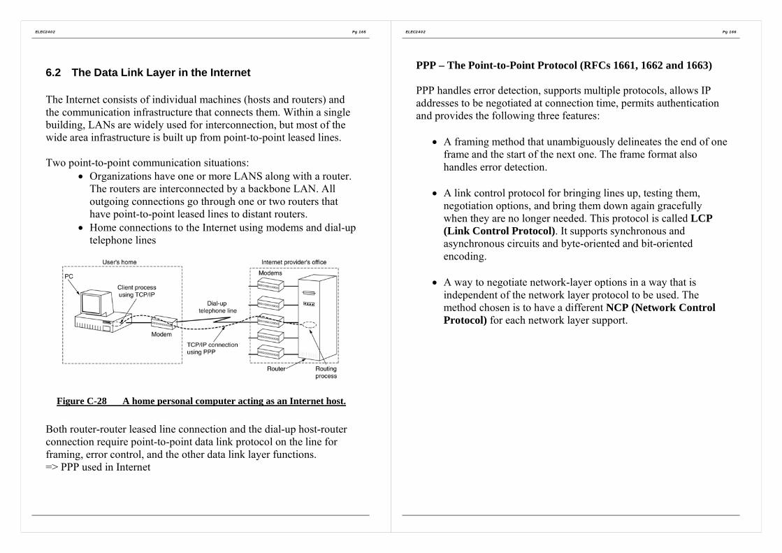
ELEC2402 Pg 165
6.2 The Data Link Layer in the Internet
The Internet consists of individual machines (hosts and routers) andthe communication infrastructure that connects them. Within a singlebuilding, LANs are widely used for interconnection, but most of thewide area infrastructure is built up from point-to-point leased lines.
Two point-to-point communication situations:• Organizations have one or more LANS along with a router.
The routers are interconnected by a backbone LAN. Alloutgoing connections go through one or two routers thathave point-to-point leased lines to distant routers.
• Home connections to the Internet using modems and dial-uptelephone lines
Figure C-28 A home personal computer acting as an Internet host.
Both router-router leased line connection and the dial-up host-routerconnection require point-to-point data link protocol on the line forframing, error control, and the other data link layer functions.=> PPP used in Internet
ELEC2402 Pg 166
PPP – The Point-to-Point Protocol (RFCs 1661, 1662 and 1663)
PPP handles error detection, supports multiple protocols, allows IPaddresses to be negotiated at connection time, permits authenticationand provides the following three features:
• A framing method that unambiguously delineates the end of oneframe and the start of the next one. The frame format alsohandles error detection.
• A link control protocol for bringing lines up, testing them,negotiation options, and bring them down again gracefullywhen they are no longer needed. This protocol is called LCP(Link Control Protocol). It supports synchronous andasynchronous circuits and byte-oriented and bit-orientedencoding.
• A way to negotiate network-layer options in a way that isindependent of the network layer protocol to be used. Themethod chosen is to have a different NCP (Network ControlProtocol) for each network layer support.

ELEC2402 Pg 167
Typical scenario of a home user calling up an ISP to make a homepc a temporary Internet host:
1. PC calls the provider router via a modem. A physicalconnection is established.
2. PC sends the router a series of LCP packets in the payload fieldof one or more PPP frames. These packets and their responsesselect the PPP parameters to be used.
3. Once the parameters have been agreed, a series of NCP packetsare sent to configure the network layer. Typically the PC wantsto run a TCP/IP protocol stack, it needs an dynamic IP address.The NCP for IP assigns the IP address.
4. Then the PC is now an Internet host and can send and receive IPpackets.
5. When the user is finished, NCP tears down the network layerconnection and frees up the IP address. Then LCP shuts downthe data link layer connection.
ELEC2402 Pg 168
The PPP Frame format:
Figure C-29 The PPP full frame format for unnumbered modeoperation.
Flag All PPP frames begin with the standard HDLC flagbyte (01111110), which is byte stuffed if it occurswithin the payload field.
Address Always set to binary value 11111111 to indicate thatall stations are to accept the frame. Using this valueavoids the issue of having to assign data linkaddresses.
Control Default is 00000011 which indicates an unnumberedframe. In other words, PPP does not provide reliabletransmission using sequence numbers andacknowledgements as the default.
Protocol Specifies what kind of packet is in the Payload field.Codes are defined for LCP,NCP, IP IPX, AppleTalk,and other protocols. The default size of the protocolfield is 2 bytes, but it can be negotiated down to 1byte using LCP.
Payload Variable length, up to some negotiated maximum,default length is 1500 bytes, if the length is notnegotiated using LCP during line setup.
Checksum Default is 2 bytes, but a 4 byte checksum can benegotiated.

ELEC2402 Pg 169
PPP communication phases:
Figure C-30 A simplified phase diagram for bringing a line up anddown.
The protocol starts with the line in the DEAD state. After physicalconnection is established, the line moves to ESTABLISH. LCP optionnegotiation begins, if successful, leads to AUTHENTICATE. Now thetwo parties can check on each other’s identities if desired. When theNETWORK phase is entered, the appropriate NCP protocol is invokedto configure the network layer. If the configuration is successfulOPEN is reached and the data transport can take place. When datatransport is finished, the line moves into the TERMINATE phase, andfrom there, back to DEAD when the carrier is dropped.
ELEC2402 Pg 170
Section D
The Medium Access Control SubLayer
1. The Channel Allocation Problem
2. Multiple access protocols
3. Ethernet

ELEC2402 Pg 171
Introduction
Access to the medium by multiple stations
Main applicationsShared medium peer-to-peer communication networks broadcastinginformation to every station.
Protocols specially defined for this kind of networks concern mainlywith the transmission of blocks of data over the shared medium whichcontains a broadcast channel (multi-access channel, random accesschannel).
Different protocols are used for networks with different shared mediaand different configurations. Therefore, in the multiple accessenvironments, there is a distinct function: controlling the access to theshared medium by multiple stations. It is better to have a sub-layer inthe data link layer to perform this function.
ELEC2402 Pg 172
1. The Channel Allocation Problem
To allocate a single broadcast channel among competing users.
(a) Static Channel Allocation in LANs (Local Area Network) andMANs (Metropolitan Area Network)
In this scheme, a user will be allocated a fix portion of thechannel (frequency band, time slot). It is suitable for networkswith uniform traffic (non-bursty traffic) among stations becauseno need to negotiate for access.
FDMA and TDMA are also the base technologies of multipleaccess networks.
(b) Dynamic Channel Allocation in LANs and MANs
There is no strict ordering of the contending stations to gainaccess to the channel. This may lead to contention and thusrequire another transmission.

ELEC2402 Pg 173
2. Multiple access protocols
i) ALOHA
(a) Aloha – does not require global time synchronization(b) Slotted Aloha - require global time synchronization
(a) Pure ALOHA• Basic Idea:
Let users transmit whenever they have data to be sent.If there is a collision (i.e. another user is transmitting at the sametime), the colliding frames will be damaged. Due to the feedbackproperty of broadcasting, a sender can always find out whetherits frame was destroyed by listening to the channel
Figure D-1 In pure ALOHA, frames are transmitted at completelyarbitrary times.
In pure ALOHA, frames are transmitted at completely arbitrarytimes.Whenever two frames try to occupy the channel at the same time(or even only a bit of frame is overlapped), there will be acollision and both will be garbled.
ELEC2402 Pg 174
(b) Slotted ALOHA• Divide time into discrete intervals, each interval corresponding to
one frame.• Each user required to transmit on slot boundaries.• Throughput =1/e or about 0.368, twice of pure ALOHA.
UserABCDEIn slotted ALOHA, each user required to transmit on slotboundaries.
Figure D-2 Throughput versus offered traffic for ALOHA systems.
Time

ELEC2402 Pg 175
ii) Carrier Sense Multiple Access Protocols
Before a station transmits, it ‘listens’ to the channel, checking ifthe channel is idle. If the carrier is sensed, it defers transmissionuntil the channel is idle; otherwise, it transmits.
There are a number of them have be proposed.
(1) 1-persistent CSMAWhen station detects an idle channel, it transmits a framewith a probability of 1.
(2) p-persistent CSMAApplies to slotted channels.When a station senses a carrier in the channel, it does nottransmit but persists to listen. When the channel is sensedidle, the station transmits with a probability p. With aprobability q=1-p, it defers until the next slot. If that slot isalso idle, it either transmits or defers again, withprobabilities p and q.
(3) Non-persistent CSMAWhen the channel is sensed busy, the station does not persistto listen. It schedules the frame to be transmitted after arandom period of time.
ELEC2402 Pg 176
(4) CSMA with Collision Detection (CSMA/CD)If two stations sense the channel to be idle and begintransmitting simultaneously, they will both detect thecollision almost immediately. Rather then finishtransmitting their frames, which are irretrievably garbledanyway, they should abruptly stop transmitting as soon asthe collision is detected.
Figure D-3 CSMA/CD can be in one of three states: contention,transmission, or idle.
Figure D-4 Comparison of the channel utilization versus load forvarious random access protocols.

ELEC2402 Pg 177
iii) Collision-Free Protocols
As the propagation time τ becomes larger, the detection time (2τ)becomes longer . This would impose serious performancedegradation if the frames are comparatively short (e.g. firer opticnetwork).
Bitmap-Map ProtocolThis is a distributed collision-free scheme. A contention periodconsists of exactly N slots according to the number of stations. Astation announces its intention to transmit by sending a ‘1’ duringthe contention slot corresponding to its station number. After thecontention period, every station knows all exactly which stationswant to transmit. Then the stations start to transmit one after theother according to their numerical order. Since every stationknows the exact order of transmission, therefore free of collisions.
Figure D-5 The basic bit-map protocol.
Marking a bit in a contention slot is like making a reservationbefore transmission starts. Therefore, this kind of protocols iscalled reservation protocol.
ELEC2402 Pg 178
Assume that time can be measured in terms of units of thecontention bit slot and that it takes d units to transmit a frame.
At light load (only one station transmits),
Efficiency=d
d N+
At heavy load (all stations transmit),
Efficiency= 1d
d +
Binary Countdown• The overhead in the bit-map protocol is 1 bit per station.
Therefore N bits is required for N station, so it does notscale well to networks with thousands of stations. If thereservation is made based on the binary addresses of thestations, the overhead bits can be redacted to 2log N
• There are only 2log N contention slots• Stations transmit ith bit of their address during ith contention
slot. Assume that ‘1’ dominates over ‘0’ (i.e. OR function).• Each station compares the resulting bit in ith contention slot
with its ith address bit. If equal, it continues with thecontention exercise. If no, it drops out of the race.
• This scheme favors stations with higher address numbers.They force those lower-numbered stations to drop out of therace.
• Overhead per frame = 2log N
• Efficiency =2log
dd N+

ELEC2402 Pg 179
(iv) Limited-Contention Protocols
Problem with collision protocols (CSMA)At light load, delay is low.As load increases, probability of collision increases => higherdelay.
Problem with collision-free protocolsAt light load, the delay is high.As load increases, the channel efficiency improves.
• Combine the beat properties of both:Use contention at light load and use collision-free at highload. ==> Limited-Contention protocols
Example: The Adaptive Tree Walk Protocol• When there is conflict, need to locate stations causing
conflicts and allocate channel accordingly. Linear search istime-consuming. Can use a tree walk algorithm to resolvecontention when conflict occurs.
• If there is a collision, the stations are recursively dividedinto groups until the conflict is resolved. (For binary tree,the number of groups is 2.) This splitting and searchingprocess is like climbing a tree in a depth first manner.
• Consider a binary tree structure. Each station is taken as aleaf on the tree. Stations are assigned contiguous binarynumbers. Each visited node in the tree corresponds to a slot.
1. Start from the root node which corresponds to Slot 0,during which all stations are permitted to acquire thechannel.If there is no collision, there is no station intending totransmit during this slot. Repeat this step (i.e. slot 0)again.
ELEC2402 Pg 180
2. If there is a collision in slot0, need to search for thecolliding stations into order to resolve conflict.Split the stations into two groups (left and rightsubtrees). This is like climbing the tree one leveltowards the leaves.Stations in the left sub-tree are those with ‘0’ as themost significant address bit. These stations are allowedto transmit in the next slot, slot 1.Stations in the right sub-tree are those with ‘1’ as themost significant address bit and are not allowed totransmit in slot 1.
3. If here is no collision in slot 1, further split thesubtrees into left and right sub-trees.Only those stations with ‘00’ as the m.s. address bitsare allowed to transmit in the next slot, slot 2. (This isequivalent to further climbing towards the leaves alongthe left sub-tree).If there is no collision in slot 1, only those stationswith ‘01’ as the m.s. address bits are allowed totransmit in the next slot, slot 2. this is equivalent tofinishing the search with the left sub-tree and goingback to climb (Search) the right sub-tree.
4. The above steps are repeated in a similar manner untilall the conflicts occurring in slot 0 have beencompletely solved.
0 1
00 01

ELEC2402 Pg 181
(v) Wavelength Division Multiple Access protocols(Similar concept to FDM)
• A fixed-wavelength receiver for listening to its own controlchannel.
• A tunable transmitter for sending on other stations’ controlchannels.
• A fixed-wavelength transmitter for outputting data frames.• A tunable receiver for selecting a data transmitter to listen to.
Figure D-6 Wavelength division multiple access.
ELEC2402 Pg 182
(vi) IEEE 802.11 - Wireless LAN
Based on cellular architecture.
Each cell is called a Basic Service Set, BSS, controlled by a basestation, known as access point, AP.
APs are connected together by a backbone network known asdistribution system, DS. e.g. Ethernet.
Basic access method: CSMA/CA (CSMA= Carrier SenseMultiple Access, CA = Collision Avoidance)
Figure D-7 Wireless LAN Architecture.

ELEC2402 Pg 183
where as MAC = Medium Access ControlFigure D-8 IEEE 802.11 Protocol Architecture.
ELEC2402 Pg 184
MACA (Multiple Access with Collision Avoidance):
In some wireless network, simultaneous transmissions areallowed as long as these transmissions are aimed at differentdestinations which are out of the range from one another.
Consider the following two cases in a wireless network:
(i) Hidden terminals
A can hear B and C, but B and C cannot hear (are hiddenfrom) each other.When B transmits to A, C does not know about this andtransmits. ==> collision.
(ii) Exposed terminals
B sends to A while C sends to D. These two pairs are indifferent areas.But C hears (is exposed to) B and so C backs offunnecessarily.

ELEC2402 Pg 185
CSMA/CA is not suitable for these situations because anyCSMA scheme senses if there is any carrier around a sensingstation (not the receiver). But to handle the hidden and exposedterminal problems, need to know if there is any activity aroundthe receiver.
==> Multiple Access Collision Avoidance (MACA)
The idea is that a sender stimulates the receiver to send out ashort frame so that the nearby stations hear this frame and willnot transmit. Therefore collision can be avoided.
(1) Before a ready station transmits, it sends a request-to-send(RTS) message to the destination station. RTS includes thelength of the data frame to be sent.
(2) When a station receives a RTS, it returns a clear-to-send(CTS) message to the sender. CTS includes the length of thedata frame to be transmitted from the sender. The lengthinformation can be directly copied from RTS.
(3) On receiving a CTS, the sender can send the data frame tothe receiver.
(4) The receiver acknowledges the data frame.
The control messages are sent using CSMA/CD or CSMA/CA.
ELEC2402 Pg 186
3. Ethernet
Ethernet (CSMA/CD put into practice)The deployed the CSMA/CD protocols that has a number of variants includingthe (IEEE 802.3).
(Refer to the Supplementary Note for Ethernet)
Ethernet cabling
Figure D-9 The most common kinds of Ethernet cabling
Figure D-10 Three kinds of Ethernet cabling. (a) 10Base5. (b) 10Base2.(c) 10Base-T.

ELEC2402 Pg 187
Manchester Encoding
Figure D-11 (a) Binary encoding. (b) Manchester encoding. (c)Differential Manchester encoding.
• Advantages for Manchester encodingEvery bit period has a transition in the middle, making it easyfor the receiver to synchronize with the sender.
• Disadvantages for Manchester encodingRequires twice as much bandwidth as straight binary encoding.
• All Ethernet systems use Manchester encoding due to itssimplicity. The high signal is +0.85 volts and the low signal is –0.85 volts, giving a DC value of 0volts. Ethernet does not usedifferential Manchester encoding, but other LANs (e.g. 802.5token ring) do use it.
The Ethernet MAC Sublayer Protocol
Figure D-12 Frame formats. (a) DIX Ethernet. (b) IEEE 802.3
ELEC2402 Pg 188
The binary Exponential backoff algorithm (of the CSMA/CD)After I collision, a random number between 0 and 2 1i − ischosen and that number of slots is skipped.
Ethernet PerformanceNow let us examine the performance of Ethernet under conditions ofheavy and constant load, that is, k stations always ready to transmit. Ifeach station transmits during a contention slot with probability p, theprobability A that some station acquires the channel in that slot is
1(1 )kA kp p −= −A is maximized when p=1/k, with A =>1/e as k =>∞.
The probability that the contention interval has exactly j slots in it is1(1 ) jA A −− , so the mean number of slots per contention is given by
1
0
1(1 ) j
jjA A
A
∞−
=
− =∑
Since each slot has a duration 2τ , the mean contention interval, ω , is2 / Aτ . Assuming optimal p, the mean number of contention slots isnever more then e, so ω is at most 2 5.4eτ τ≈ .
If the mean frame takes P sec to transmit, when many stations haveframes to send,
Channel efficiency = 2 /P
P Aτ+

ELEC2402 Pg 189
Let, F= frame length, B = network bandwidth, L = cable length, c =speed of signal propagation, P=F/B
Channel efficiency =1
1 2 /BLe cF+
Figure D-13 Efficiency of Ethernet at 10 Mbps with 512-bit slot times.
Efficiency of Ethernet at 10Mbps with 512-bit slot times and 2τ=51.2µsec.
ELEC2402 Pg 190
Section E
The Network Layer (Layer 3)
1. Network layer design issues
2. Routing Algorithms
3. Congestion control algorithms
4. Quality of service
5. Internetworking
Provides end-to-end communication capability to the higher layer(transport layer in OSI), while data link layer deals with point-to-pointcommunications.
Network layer design issues• Routing• Congestion control algorithms• Quality of service• Internetworking

ELEC2402 Pg 191
1. Network layer design issues
Some issues that the designers of the network layer must grapple with:
(i) Store-and-Forward Packet Switching(ii) Services provided to the transport layer(iii) Connectionless service(iv) Connection-oriented service(v) Comparison of Connectionless and Connection-oriented service
(i) Store-and-Forward Packet Switching
Figure E-1 The environment of the network layer protocols
A host with a packet to send transmits it to the nearest router, either onits own LAN or over a point-to-point link to the carrier. The packet isstored there until it has fully arrived so the checksum can be verified.Then it is forwarded to the next router along the path until it reachesthe destination host, where it is delivered.
ELEC2402 Pg 192
(ii) Services provided to the transport layer• Independent of router technology.• The transport layer should be shield from the number, type, and
topology of the routers present.• The network addresses made available to the transport layer
should use a uniform numbering plan, even across LANs andWANs.
Depending on type of service offered, two different organizations arepossible:
Connectionless service andConnection-oriented service
(iii) Connectionless service (CL)Transfer of independent data units (datagrams) without theestablishment and maintenance of a network connection. Someapplications require this mode of service. e.g.
• LANs because connections are basically point-to-point.• Networks or gateways where fast performance is required Much simpler protocols than connection-mode data transfer
Involving only two-parties: network services (NS) user and networkservices provider.
There is a prior agreement between the NS-users (NS-entities).Once service primitive operation has taken place, no furthercommunication occurs between NS-provider and NS-userconcerning the fate or subsequent disposition of the CL data units.
Since CL data units are independent,• CL data units can be sent along different network paths;• The order of arrival of CL data units can be different from that of
sending.
No flow control.

ELEC2402 Pg 193
(iv) Connection-Oriented service (CO)Three phases:(a) Establishment phase
• Network service user and network service provider agree to setup a network connection (NC).
• A route from the source machine and destination machine ischosen as part of the connection setup and stored in tablesinside the routers that form a virtual-circuit subnet.
(b) Data transfer phase• Data units can be transfer in either direction.
(c) Release phase• Both machines agree to terminate the connection.
ELEC2402 Pg 194
(v) Comparison of Connectionless and Connection-orientedservice
Issue ConnectionlessService
Connection-orientedservice
Circuit setup Not needed RequiredAddressing Each packet contains
the full source anddestination address
Each packet contains ashort virtual circuit (VC)number
Stateinformation
Routers do not holdstate informationabout connections
Each VC requires routertable space perconnection
Routing Each packet is routedindependently
Route chosen when VC isset up; all packets followit
Effect ofrouter failures
None, except forpackets lost duringthe crash
All VCs that passedthrough the failed routerare terminated
Quality ofservice
Difficult Easy if enough resourcescan be allocated inadvance for each VC
Congestioncontrol
Difficult Easy if enough resourcescan be allocated inadvance for each VC

ELEC2402 Pg 195
2. Routing Algorithms
Network routing concerns with the algorithm at each node in anetwork in determining to which link a packet should be forwarded.
Routing affects:• average delay• network flow capacity
Desirable properties of a routing algorithm:• Correctness• Simplicity• Robustness: can cope with node/link failure, traffic fluctuation
and topology change.• Stability converge to equilibrium• Fairness• Optimality: delay of an individual packet, average packet
delay, throughput, cost, number of hops.
Fairness and optimality are often conflicting.
Some routing algorithms require exchange of control messages. Thesecontrol messages are extra traffic due to the implementation of routingalgorithms.
ELEC2402 Pg 196
2.1 The optimality principleIt states that if router J is on the optimal path from router I torouter K, the optimal path from J to K also falls along the sameroute.
Static algorithm• Shortest path routing• Flooding
Dynamic algorithm• Distance vector routing• Line state routing
2.2 Shortest Path routingDijkstra (1959)Each node is labeled with its distance from the source node alongthe best-known path. Initially, no paths are known, so all nodesare labeled with infinity. As the algorithm proceeds and paths arefound, the labels may change, reflecting better paths. A label maybe either tentative or permanent. Initially, all labels are tentative.When it is discovered that a label represents the shortest possiblepath from the source to that node,, it is made permanent andnever changed thereafter.

ELEC2402 Pg 197
Figure E-2 The first five steps used in computing the shortest pathfrom A to D. The arrows indicate the working node.
ELEC2402 Pg 198
2.3 Flooding
Initially an originating node sends a packet to each of its neighbours.Each node on receiving a packet checks whether that packet has beenreceived before. If yes, discard it. If no, forward it to all the neighbournodes except the one from which the packet was sent. Therefore,every node receives the packet (flooding) and finally the destinationabsorbs it.
Advantages:• Always able to route a packet to its destination as long as such a
possible route exists.• Resilience to node & link failures (flows along every possible
paths).• Independent of topology• Easy in computing the route• Fast routing
Disadvantages extra traffic (flooding):• Therefore, flooding is good for very lightly loaded network. To
reduce the extra traffic induced by flooding, can limit the life of apacket. Attach a hop count in the header of a packet each time itarrives at a node, this count is decreased by one. If the countbecomes zero, the packet will be discarded. This count can beconveniently set to the diameter of the network, i.e. themaximum of the minimum distance (number of hops) betweenany two nodes.

ELEC2402 Pg 199
2.4 Distance vector routingARPANET was a research project sponsored by the Department ofDefence (DOD) of U.S.A. ARPANET is the foundation of today’sInternet.
ARPANET has a layer called Internet Layer, which corresponds to theNetwork Layer in OSI. The Internet layer is a connectionless layerusing a distributed adaptive routing algorithm.
The routing algorithm used in ARPANET is a form of distance-vectorrouting. The routing protocol used in the Internet (RoutingInformation Protocol, RIP) is also based on this algorithm.
In a distance-vector routing algorithm, each router (a node taking partin routing) maintains a routing table. If there are N routing nodes inthe network, there are N entries in this table, one for each node. Therouting table is indexed by the destination node number (oralternatively, stored as a separate column). Each table entry containstwo parts:
1. The preferred outgoing link (node) for packets to be routedto that destination.
2. Estimate of the distance (cost) to that destination. Thisestimate is initialized to infinity.
The term “distance” used here refers to a metric used to help makingrouting decision. The metric can be number of hops, time delay,packet queues along the route, …etc. some systems may have multiplemetrics.
At a fixed interval (e.g. 10 sec for ARPANET, 30 sec for RIP), eachnode exchanges its distance vector with all of its neighbours. Thisinformation will eventually propagates (advertise) throughout thenetwork. Therefore, distance-vector routing is a kind of routeadvertising protocols and the updating process is illustrated in FigureE-3.
ELEC2402 Pg 200
Figure E-3 (a) A subnet. (b) Input from A, I, H , K, and the newrouting table for J.
The ARPANET routing algorithm has the following problems:• Tends to favour links with shorter queues. Queue length can
change rapidly. While a packet is being routed, it maycontinue in seeking for area with low congestion -> flashing.
• Link speed and packet size are not considered.• Slow response to traffic changes.• Not robust enough, e.g. count-to-infinity problem.
Measured or estimated by J→
(via)

ELEC2402 Pg 201
Count-to-infinity problem
Figure E-4 The count-to-infinity problem to A.
Consider Figure E-4, in which all the lines and routes are initially up.Suddenly A goes down, or alternatively, the line between A and B iscut, which is effectively the same thing from B’s point of view.At the first packet exchange, B does not hear anything from A.fortunately, C says: Do not worry; I have a path to A of length 2.Little does B know that C’s path runs though B itself. For all B knows,C might have ten lines all with separate paths to A of length 2. As aresult B thinks it can reach A via C, with a path length of 3. D and Edo not update their entries for A on the first exchange.
On the second exchange, C notices that each of its neighbors claims tohave a path to A of length 3. It picks one of them at random andmakes its new distance to A 4, as shown in the third row of Figure E-4.Subsequent exchanges produce the history shown in the rest of FigureE-4.
One of possible ways to solve this problem is to include the pathinformation in the distance vector. This method is called path-vectoras used in border gateway protocol (BGP).
ELEC2402 Pg 202
2.5 Line State Routing
The routing algorithm of ARPANET was later modified so that delayis taken as the metric instead of quene length.
The delay of a packet is measured directly. As a packet arrives at anode, its arrival time is also noted. Arrival time is the time that thepacket is transmitted successfully (i.e. after properly acknowledged).The delay of a packet was calculated according to these time-stamps.
A node calculates the average delay on each outgoing link over aperiod (for ARPANET, 110 seconds). If there is an insignificantchange, the node sends the delay information to all other nodes bymeans of flooding. On receiving new delay information, a node re-computes the routing table.
Problem: under heavy load situation, almost immediately after theupdating of the routing table, the table becomes obsolete.Solution: instead of trying to obtain the best route for all destinationsgive the average route a good path.
This is done by measuring the average delay over the last n seconds(e.g. 10 sec for ARPANET). Transform the delay measurement intoan estimated link cost (utilization). At the end of a measurementperiod, if the change of cost is significant, the computed link cost isreported (in the form of a link state packet, LSP) to all other routers inthe network by flooding. A router sends a sequence of LSPs, one foreach neighbour. A LSP from a router contains:
• ID of the router• ID of its neighbour• Cost of the link to its neighbour

ELEC2402 Pg 203
In this way, each router receives not just the cost information but alsothe topological information (since LSP from a router contains the IDof its neightbour). This additional information helps to preventlooping problems (e.g. count-to-infinity), which are due to the lack oftopological information of the network. A router may also requestanother router for its LSP. Each router maintains the received LSPinformation in a LSP database. A router uses this database tocomputer the optimal routes to all destinations according to certainalgorithm. Dijkstra’s shortest-path algorithm (or its variation) iscommonly used.
ELEC2402 Pg 204
3. Congestion control algorithms
A packet network can be modeled as a pool of resources in terms ofchannels, buffers and switches.
Unrestricted or uncontrolled competition for the resources may cause:• Inefficiency Resources are wasted• Unfairness Some users capture large source of resources than
others.• Congestion Part of the network becomes a bottleneck &
throughput drops as a result. Worst case: deadlock.
Figure E-5 When too much traffic is offered, congestion sets in andperformance degrades sharply.
In packet network, flow control procedures are used to solve theseproblems.

ELEC2402 Pg 205
3.1 General Principles of congestion control• Monitor the system to detect when and where congestion occurs.• Pass this information to places where action can be taken• Adjust system operation to correct the problem
3.2 Congestion prevention policiesIn Figure E-6, different data link, network, and transport policies thatcan affect congestion are shown.
Figure E-6 Policies that affect congestion
ELEC2402 Pg 206
3.3 Congestion control in virtual-circuit subnetsOnce the congestion has been signaled, no more virtual circuits are setup until the problem has gone away.
3.4 Congestion control in datagram subnets
Each router can easily monitor the utilization of its output lines andother resources. In case of congestion control, several actions can betaken.
The warning bitSet by router in the packet the congestion warning state. Thedestinations copied the bit into the next acknowledgement sentback to the source. As long as the warning bits continued to flowin, the source continued to decrease its transmission rate.
Choke packetsThe router sends a choke packet back to the source host directlyto request it to slow down the traffic.
Hop-by-Hop chock packetsSame as choke packets, except the effect takes at every hop itpasses through.
3.5 Load SheddingWhen none of the above methods make the congestion disappear,routers can bring out he heavy artillery: load shedding by randomlythrow packets out, except packets marked with “VERYIMPORTANT –NEVER, EVER DISCARD”.

ELEC2402 Pg 207
4. Quality of service
With the growth of multimedia networking, often ad hoc messages arenot enough. Serious attempts at guaranteeing quality service throughnetwork and protocol design are needed.
4.1 RequirementsA stream of packets from a source to a destination is called a flow. Ina connection-oriented network, all the packets belonging to a flowfollow the same route; in a connectionless network, they may followdifferent routes. The needs of each flow can be characterized by fourprimary parameters: reliability, delay, jitter (the variation (i.e.,standard deviation) in the packet arrival times is called jitter), andbandwidth. Together these determine the QoS (Quality of Service) theflow requires. Several common applications and stringency of theirrequirements are listed below.
Figure E-7 How stringent the quality-of-service requirements are.
ELEC2402 Pg 208
ATM networks classify flows in four broad categories with respect totheir QoS demands as follows:Constant bit rate (e.g., telephony).Real-time variable bit rate (e.g., compressed videoconferencing).Non-real-time variable bit rate (e.g., watching a movie over theInternet).Available bit rate (e.g., file transfer).
These categories are also useful for other purposes and other networks.
4.2 Techniques for Achieving Good Quality of Service
OverprovisioningAn easy solution is to provide so much router capacity, buffer space,and bandwidth that the packets just fly through easily.
BufferFlows can be buffered on the receiving side before being delivered.Buffering them does not affect the reliability or bandwidth, andincreases the delay, but it smoothes out the jitter. For audio and videoon demand, jitter is the main problem, so this technique helps a lot.
Figure E-8 Smoothing the output stream by buffering packets.

ELEC2402 Pg 209
Traffic Shaping
Non-uniform output is common if the server is handling many streamsat once, and it also allows other actions, such as fast forward andrewind, user authentication, and o on. Also, the approach we used here(buffering) is not always possible, for example, withvideoconferencing. However, if something could be done to make theserver (and hosts in general) transmit at a uniform rate, quality ofservice would be better.
Traffic shaping = smooths out the traffic on the server side, rather thanon the client side.
Traffic shaping is about regulating the average rate (and burstiness) ofdata transmission. In contrast, the sliding window protocols limit theamount of data in transit at once, not the rate at which it is sent. Whena connection is set up, the user and the subnet agree on a certain trafficpattern for that circuit. Sometimes this is called a service levelagreement. As long as the customer fulfills her part of the bargain andonly sends packets according to the agreed-on contract, the carrierpromises to deliver them all in a timely fashion.
ELEC2402 Pg 210
The Leaky bucket Algorithm
Imagine a bucket with a small hole in the bottom, as illustrated inFigure E-9(a). No matter the rate at which water enters the bucket, theoutflow is at a constant rate, when there is any water in the bucket andzero when the bucket is empty. Also, once the bucket is full, anyadditional water entering it spills over the sides and is lost.
The same idea can be applied to packets, as shown in Figure E-9(b).Conceptually, each host is connected to the network by an interfacecontaining a leaky bucket, that is a finite internal queue. If a packetarrives at the queue when it is full, the packet is discarded. In otherwords, if one or more processes within the host try to send a packetwhen the maximum number is already queued, the new packet isunceremoniously discarded.
Figure E-9 (a) A leaky bucket with water. (b) A leaky bucket withpackets.

ELEC2402 Pg 211
The Token Bucket Algorithm
The leaky bucket algorithm enforces a rigid output pattern at theaverage rate, no matter how bursty the traffic is. For manyapplications, it is better to allow the output to speed up somewhatwhen large bursts arrive, so a more flexible algorithm is needed,preferably one that never loses data. => Token Bucket Algorithm.
In this algorithm, the leaky bucket holds tokens, generated by a clockat the rate of one token every T sec. In Figure E-10(a), a bucketholding three tokens, with five packets waiting to be transmitted. For apacket to be transmitted, it must capture and destroy one token. InFigure E-10(b) three of five packets have gotten through, but the othertwo are stuck waiting for two more tokens to be generated.
Figure E-10 The token bucket algorithm. (a) Before. (b) After.
ELEC2402 Pg 212
Resource ReservationBeing able to regulate the shape of the offered traffic is a good start toguaranteeing the quality of service. However, effectively using thisinformation implicitly means requiring all the packets of a flow tofollow the same route. Spraying them over routers at random makes ithard to guarantee anything. As a consequence, something similar to avirtual circuit has to be set up from the source to the destination, andall the packets that belong to the flow must follow this route.
Admission ControlBecause many parties may be involved in the flow negotiation (thesender, the receiver, and all the routers along the path between them),flows must be described accurately in terms of specific parametersthat can be negotiated. A set of such parameters is called a flowspecification. Typically, the sender (e.g., the video server) produces aflow specification proposing the parameters it would like to use. Asthe specification propagates along the route, each router examines itand modifies the parameters as need be. The modifications can onlyreduce the flow, not increase it (e.g., a lower data rate, not a higherone). When it gets to the other end, the parameters can be established.
Proportional RoutingMost routing algorithm try to find the best path for each destinationand send all traffic to that destination over the best path. A differentapproach that has been proposed to provide a higher quality of serviceis to split the traffic for each destination over multiple paths. Sincerouters generally do not have a complete overview of network-widetraffic, the only feasible way to split traffic over multiple routes is touse locally available information. A simple method is to divide thetraffic equally or in proportion to the capacity of the outgoing links.However, more sophisticated algorithms are also available.

ELEC2402 Pg 213
Packet Scheduling
Fair queuing algorithmRouter have separate queues for each output line, one for eachflow. When a line becomes idle, the router scans the queuesround robin, taking the first packet on the next queue. In this way,with n hosts competing for a given output line, each host gets tosend one out of every n packets. Sending more packets will notimprove this fraction.
Problem: It gives more bandwidth to hosts that use large packetsthan to hosts that use small packets. An improvement in whichthe round robin is done in such a way as to simulate a byte-by-byte round robin, instead of a packet-by-packet round robin. Ineffect, it scans the queues repeatedly, byte-to-byte, until it findsthe tick on which each packet will be finished. The packets arethen sorted in order of their finishing and sent in that order. Thealgorithm is illustrated in Figure E-11.
Figure E-11 (a) A router with five packets queued for line O. (b)Finishing times for the five packets.
ELEC2402 Pg 214
4.3 Integrated Services
Between 1995 and 1997, IETF (Internet Engineering Task Force)devising an architecture for streaming multimedia. This work resultedin over two dozen RFCs, starting with RFCs 2205-2210. The genericname for this work is flow-based algorithms or integrated services.
RSVP – The Resource reservation Protocol
The main IETF protocol for the integrated services architecture isRSVP. It is described in RFC 2205 and others. This protocol is usedfor making the reservations; other protocols are used for sending thedata. RSVP allows multiple senders to transmit to multiple groups ofreceivers, permits individual receivers to switch channels freely, andoptimizes bandwidth use while at the same time eliminatingcongestion.
In its simplest form, the protocol use multicast routing using spanningtrees. Each group is assigned a group address. To send to a group, asender puts the group’s address in its packets. The standard multicastrouting algorithm then builds a spanning tree covering all groupmembers. The routing algorithm is not part of RSVP. The onlydifference from normal multicasting is a little extra information that ismulticast to the group periodically to tell the routers along the tree tomaintain certain data structures in their memories.
As an example, consider the network of Figure E-12. Hosts 1 and 2are multicast senders, and hosts 3, 4, and 5 are multicast receivers. Inthis example, the senders and receivers are disjoint, but in general, thetwo sets may overlap. The multicast trees for hosts 1 and 2 are shownin Figure E-12(b) and Figure E-12(c), respectively.

ELEC2402 Pg 215
Figure E-12 (a) A network. (b) The multicast spanning tree for host 1.(c) The multicast spanning tree for host 2
Every client can send a reservation message (flow descriptor) to itsupstream router, specifying the desired QOS (Quality of services) andthe set of packets to receive in a session. On receiving a reservationmessage, a router allocates its resources and adjusts its packetscheduler to meet the request. It then in turn sends a reservationmessage to the next upstream router. Reservations received by a routerare merged. An example of such a reservation is shown in Figure E-13below.
Figure E-13 (a) Host 3 requests a channel to host 1. (b) Host 3 thenrequests a second channel, to host 2. (c) Host 5 requests a channel to host1.
ELEC2402 Pg 216
4.4 Differentiated Services
Flow-based algorithms have the potential to offer good quality ofservice to one or more flows because they reserve whatever resourcesare needed along the route. However, they also have a downside.They require an advance setup to establish each flow, something thatdoes not scale well when there are thousands or millions of flows.Also, they maintain internal per-flow state in the routers, making themvulnerable to router crashes. Finally, the changes required to the routercode are substantial and involve complex router-to-router exchangesfor setting up the flows. As a consequence, few implementations ofRSVP or anything like it exist yet.
For these reasons, IETF has also devised a simpler approach to qualityof service, one that can be largely implemented locally in each routerwithout advance setup and without having the whole path involved.This approach is known as class-based (as opposed to flow-based)quality of service. IETF has standardized an architecture for it, calleddifferentiated services.
Differentiated services (DS) can be offered by a set of routers formingan administrative domain (e.g., an ISP or a telco). The administrationdefines a set of service classes with corresponding forwarding rules. Ifa customer signs up for DS, customer packets entering the domainmay carry a type of service field in them, with better service providedto some classes (e.g., premium service) than to others. Traffic within aclass may be required to conform to some specific shape, such as aleaky bucket with some specified drain rate. An operator with a nosefor business might charge extra for each premium packet transportedor might allow up to N premium packets per month for a fixedadditional monthly fee. Note that this scheme requires no advancesetup, no resource reservation, and no time-consuming end-to-endnegotiation for each flow, as with integrated services. This makes DSrelatively easy to implement.

ELEC2402 Pg 217
Expedited Forwarding
The choice of service classes is up to each operator, but since packetsare often forwarded between subnets run by different operators, IETFis working on defining network-independent service classes. Thesimplest class is expedited forwarding and is described in RFC 3246.
The idea behind expedited forwarding is very simple. Two classes ofservice available: regular and expedited. The vast majority of thetraffic is expected to be regular, but a small fraction of the packets areexpedited. The expedited packets should be able to transit the subnetas though no other packets were present.. a symbolic representation ofthis “two-tube” system is given in Figure E-14. Note that there is stilljust one physical line. The two logical pipes shown in the figurerepresent a way to reserve bandwidth, not a second physical line.
One way to implement this strategy is to program the routers to havetwo output queues for each outgoing line, one for expedited packetsand one for regular packets.
Figure E-14 Expedited packets experience a traffic-free network.
ELEC2402 Pg 218
Assured Forwarding
Described in RFC 2597. It specifies that there shall be four priorityclasses, each class having its own resources. In addition, it definesthree discard probabilities for packets that are undergoing congestion:low, medium, and high. Taken together, these two factors define 12service classes.
Figure E-15 shows one way packets might be processed under assuredforwarding. Step 1 is to classify the packets into one of the fourpriority classes. This step might be done on the sending host (asshown in the figure) or in the ingress (first) router. The advantage ofdoing classification on the sending host is that more information isavailable about which packets belong to which flows there.
Figure E-15 A possible implementation of the data flow for assuredforwarding.

ELEC2402 Pg 219
Step 2 is to mark the packets according to their class. A header field isneeded for this purpose. Fortunately, an 8-bit Type of service field isavailable in the IP header, as we will see shortly. RFC 2597 specifiesthat six of these bits are to be used for the service class, leavingcoding room for historical service classes and future ones.
Step 3 is to pass the packets through a shaper/dropper filter that maydelay or drop some of them to shape the four streams into acceptableforms, for example, by using leaky or token buckets. If there are toomany packets, some of them may be discarded here, by discardcategory. More elaborate schemes involving metering or feedback arealso possible.
In this example, these three steps are performed on the sending host,so the output stream is now fed into the ingress router. It is worthnoting that these steps may be performed by special networkingsoftware or even the operating system to avoid having to changeexisting applications.
ELEC2402 Pg 220
4.5 Label Switching and MPLS
While IETF was working out integrated services and differentiatedservices, several router vendors were working on better forwardingmethods. This work focused on adding a label in front of each packetand doing the routing based on the label rather than on the destinationaddress. Making the label an index into an internal table makesfinding the correct output line becomes just a matter of table lookup.Using this technique, routing can be done very quickly and anynecessary resources can be reserved along the path.
This “new” switching idea goes by various (proprietary) names,including label switching and tag switching. Eventually, IETF beganto standardize the idea under the name MPLS (Multi-Protocol LabelSwitching) and is described in RFC 3031 and many other RFCs.
A new MPLS header is added in front of the IP header. On a router-to-router line using PPP as the framing protocol, the frame format,including the PPP, MPLS, IP, and TCP headers, is as shown in FigureE-16.
Figure E-16 Transmitting a TCP segment using IP, MPLS, and PPP.

ELEC2402 Pg 221
5. Internetworking
Until now, we have implicitly assumed that there is a singlehomogeneous network, with each machine using the same protocol ineach layer. Unfortunately, this assumption is wildly optimistic.
Many different networks exist, including LANs, MANs and WANs.
Numerous protocols are in widespread use in every layer. Even withinan organization, different networks are used at the dame time fordifferent purposes using different technologies. In fact, networks havebeen introduced over time and may not want to replace them all at thesame time.
In the following sub-sections we will take a careful look at the issuesthat arise when two or more networks are connected to form anInternet.
ELEC2402 Pg 222
5.1 Requirement for internetworking
i. Physical connection between networks, which may usedifferent physical media.
ii. Data link connection between networks.iii. Data routing between end-stations in different networksiv. Provide account service.v. Provide protocol conversion in such a way that here should
be no modifications required to the networks connected.Common protocol differences are:• Different address scheme• Different maximum packet size• Different network access• Different timeouts• Error recovery• Different status and performance reports• Different routing algorithms• Different user access control• Connection and connectionless services

ELEC2402 Pg 223
5.2 Network connection
(i) Hardware
(a) RepeatersA repeater is used to connect two network segments. It repeatsthe information received from one segment by amplifying thesignal received from that segment and then transmitting theamplified signal to the other segment. It functions at the physicallayer.
(b) BridgesA bridge is used to link two network segments, which may ormay not be of the same media types. It differs from a repeater inthat a bridge makes decision on the handling of a frame received.A bridge offers filtering and relaying (forwarding) services.Therefore, a bridge can be used to isolate two network segments.If the network segments are of different types, frame translationis required. A bridge has a protocol stack covering the physicallayer and the data link layer (MAC and LLC sub-layers).Therefore, a bridge is also called a layer device.
ELEC2402 Pg 224
(c) RoutersAn Internet contains heterogeneous networks which areconnected by special devices called router.
A router has a protocol stack, which covers the physical layer,the data link layer and the network layer. It passes (routes)packets from one network to another network so that the packetwill eventually arrives at its destination.
Figure E-17 A collection of interconnected networks.(SNA = System Network Architecture Protocol developed in
1970s by IBM,FDDI = Fiber Distributed Data Interface - ISO 9314)
As the size of Internet grows, the task of routing becomes morecomplex. Therefore, route a packet based on the destinationnetwork rather than individual station /end system (commonlycalled host).

ELEC2402 Pg 225
(ii) Protocols used for internetworking
The protocol stack commonly used in an Internet (global/private)is called TCP/IP (Transmission Control Protocol / InternetProtocol).
This protocol stack is designed to provide universal servicesamong stations independent of the network to which they areattached. Therefore, TCP/IP presents the Internet to the users as avirtual network.
Figure E-18 The Internet is an interconnected collection of manynetworks.
ELEC2402 Pg 226
Universal services:• Unique address for each host• Network equality• Host can send a packet to any other host
The protocol hides the details of physical connections, physicaladdresses and routing information from the users. It offers theusers the facilities of a large virtual network.

ELEC2402 Pg 227
Section F
Introduction to TCP (Layer 4)/ IP(Layer 3)
1. Basic operations of TCP/IP:
2. Resolution of IP address
3. IP Datagram
4. Routing of IP Datagrams/Fragments
5. Internet Control Message Protocol (ICMP)
6. Internet Multicasting
7. Transport Protocol: TCP
8. UDP Connectionless Services
ELEC2402 Pg 228
Introduction
TCP/IP can be characterized as a layered architecture as shown below.
Figure F-1 The TCP/IP reference model
TCP/IP has a protocol stack of four layers. Most of the layerscorrespond to the OSI layers. However, OSI does not have a layercorresponding to the TCP/IP Internet layer. The OSI layer closest tothe Internet layer is the Network layer.

ELEC2402 Pg 229
Layer 1: Host-networkBelow the internet layer is great void. The TCP/IP referencemodel does not say much here, except to point out that this hosthas to connect to he network using some protocol so it can sendIP packets to it and this protocol is not defined and varies fromhost to host and network to network.
Layer 2: InternetSpecify how data are put into packets and how to route a packetfrom the source host to the destination host through one or morerouters. The protocol used in this layer is called IP (InternetProtocol).
(The major difference between Internet layer and the OSInetwork layer is that he Internet layer provides a seamless virtualnetwork made up of heterogeneous networks.)
Layer 3: TransportSpecify how end-to-end data can be transferred reliably throughthe Internet. The protocol used in this layer is called TCP(Transmission Control Protocol) and UDP (User DatagramProtocol)
Layer 4: ApplicationThe layer-4 protocol specifies how an application performs dataexchange through the Internet.For example:• Telnet (virtual terminal)• FTP (File Transfer Protocol)• SMTP (simple Mail Transfer Protocol)• DNS (Domain Name Service)• HTTP (Hyper Text transfer Protocol)
ELEC2402 Pg 230
In TCP/IP the use of all layers is not mandatory.e.g. some applications use IP directly.
TCP/IP supports universal services by providing global addressing.Each host has one or more unique global addresses. Two Internethosts can identify each other by means of their global addresses.
Figure F-2 Internet Protocol Operation

ELEC2402 Pg 231
1. Basic operations of TCP/IP:
The concept of TCP/IP operations are illustrated in Figure F-2.
• Each application process (AP) in a host transmits to or receivesdata from the TCP layer via one or more ports (known asservice access point (SAP) in OSI).
The connection between the corresponding ports at the endsystems is called a TCP connection. This connection can beidentified by the corresponding port address in each host. Theidentity of a port in a host is unique in that host so that a hostcan identify a particular AP.
However, unlike a host address, a port identity is not a globaladdress. It is used to identify the communicating APs in thehosts concerned.
• TCP ensures reliable data transmission in a TCP connectionbetween the corresponding APs.(Note: TCP offers both connection and connectionless
services.)
• TCP is implemented only at the hosts (end systems).
• A TCP connection makes use of IP to exchange data with theother host through the Internet.(Note that IP does not need to know the identity of thedestination port. Its job is to route data to the destination host.The TCP in that host will use the information attached to thedata to find out the port number and send it to the appropriateapplication process.)
ELEC2402 Pg 232
• Each host can be identified by its unique global address. Thisallows ip to route data from the TCP layer to the destinationhost. If the communicating hosts are on different networks, thepath goes through one or more routers.
• IP is implemented in all the hosts as well as the routers.• IP exchanges data with the network, to which the host is
attached, via the network interface and the physical layers. E.g.IEEE 802.3 CSMA/CD,FDDI.
Therefore, two levels of addressing: IP address and port.
Figure F-3 Protocol Data Units in the TCP/IP Architeture.Data units from a layer may be fragmented when passed down to alower layer and reassembled when passed up to a higher layer.

ELEC2402 Pg 233
1.1 Internet Protocol: IP
IP Addressing Scheme
The major difference between Internet and a physical network is thatInternet is an abstraction presented by software (with the help ofrouters). The users view the Internet as a large seamless virtualnetwork connecting many hosts. In order to route data to a host, eachhost in the Internet is assigned one or more unique global addresses,the IP addresses. The IP addressing scheme must be independent ofthe underneath physical networks so that the APs can communicatewithout knowing the physical address of the other party.
Classes of IP AddressesAn Internet address has 32 bits which is divided into 2 hierarchicalparts:
• PrefixIdentifies a network number i.e. the identity of the physicalnetwork to which the host is attached. A network number is aunique number in Internet and is assigned globally by theInternet Assigned Number Authority.
• SuffixIdentifies a host on the attached network. This portion of thehost address must be unique within the boundary of theattached network, i.e. not assigned globally
Therefore, each IP address is unique in the Internet.
ELEC2402 Pg 234
Hosts in the same physical network have the same prefix.Hosts in different physical networks have different prefixed but mayhave the same suffix
Question:How many bits in each address field?Problem: Need to accommodate all sorts of network. Some are large
(therefore, need a longer suffix fields) and some are small(therefore, need a shorter suffix field).
Solution: Have different classes of IP addresses. Each class has adifferent for suffix and prefix.
There are five classes of IP address as shown below:
Figure F-4 IP address format

ELEC2402 Pg 235
Classes A to C are primary classes used for host addressing.
Class D is for multicasting. A multicast address is shared by eachmember host of a multicast group. Each member of a multicast groupmust be able to recognize its associated multicast address so that eachmember will receive a copy of the packet sent to this multicast address.
When IP receives a packet, it finds out the class of its destinationaddress. However, this frequent computational task has to be carriedout efficiently.
e.g. Can use a table to help this calculation. Bits 003 of an IP addresscan be used as an index into the following translation table:
Bits 0-3(The first
4 bits)
Decimal Value Class
0000 0 A0001 1 A0010 2 A0011 3 A0100 4 A0101 5 A0110 6 A0111 7 A1000 8 B1001 9 B1010 10 B1011 11 B1100 12 C1101 13 C1110 14 D1111 15 E
ELEC2402 Pg 236
For convenience, a dotted decimal notation is used to express the 32-bit IP addresses. An IP address is divided into sections of 8 bits. Eachsection is written down as a decimal number (ranging from 0 to 255).A dot is placed between two sections.
e,g,10100011 00001000 10110100 00010001 = 147.8.180.17The decimal value of the first octet (Bits 0-7) of an IP addressindicates its class as followings:
Class Range of Decimal Values (First Octetof IP Address)
A 0-127B 128-191C 192-223D 224-239E 240-255
The maximum number of networks and stations allowed in Classes A-C are shown in the following table:
Class Bits inPrefix
Max. No. ofNetworks
Bits inSuffix
Max. No. of StationsPer Network
A 7 128 24 16,777,216B 14 16,384 16 65,536C 21 2,097,152 8 256
There are 268,435,456 multicast addresses (28 bits).

ELEC2402 Pg 237
1.2 Special IP Addresses
There are some IP addresses reserved for special purposes as shownbelows. These addresses are not assigned to hosts.
Figure F-5 Special IP addresses.
1.3 Multi-homed hostsIt is easier to view that an IP address is assigned to a host, this idea isnot accurate. Consider the following situations in which a host isconnected to multiple networks:
• A host can be connected to more than one network forreliability or for performance. This kind o hosts is called multi-homed hosts. In order to send packets to this host alongdifferent network connections, each of its network connectionmust have a unique IP address; therefore a multi-homed hosthas multiple IP addresses.
ELEC2402 Pg 238
• In Internet, a router is also assigned with IP address. Since arouter has multiple network connections, it has multiple IPaddresses, one for each network connection.
For a host with only a single network connection, it does not matter totreat the IP address as the address of the host or the address of itsnetwork connection.
Figure F-6 Three interconnected networks: Ethernets and FDDI ring (The IPaddress are examples only and have no special meaning).
In the above diagram, each connection of a router has an IP address.The host shown in Network 3 is connected to Network 3 (an Ethernet)and Network 2 (a FDDI). Therefore there are two IP addresses for thishost, one for each connection.

ELEC2402 Pg 239
1.4 Problems with the IP Addressing Scheme
• When a host moves to another network, need to change the IPaddress. Prefix -> network number.
• When a class C network grows beyond 255 hosts, it has tochange to Class B or Class A. this implies that all the IPaddresses of the network and all its hosts must change.
• Internet routes a packet according to the IP address of itsdestination. Therefore, the route taken by packets destined to amulti-homed host depends on which IP address is used. Whichaddress should be used?
• Because of network faults, a multi-homed host may not bereached by one of its IP address but may still be reached by itsother IP addresses. Need to know all its IP addresses.
ELEC2402 Pg 240
2. Resolution of IP address
An IP address is a virtual (logical) element. It exists only in the IPsoftware. The hardware of the Internet components (networks andhosts) are not understand the IP address but only the physical(hardware) addresses. When routing a packet to a host, must know thephysical address of the next hop. Therefore, the IP protocol needs tomap (bind) an IP address to a physical address. This translation,known as address resolution, is hidden from the users.
However addresses must be resolved locally.
e.g.
Figure F-7 Two subnet connected by routers.
As shown in the diagram above, Host H1 sends data to Host H2 usingthe IP address. H1 and H2 are local stations on the same network(Network 1). The IP protocol software in H1 resolves the IP address tothe physical address of H2 and sends data to H2 using this physicaladdress.

ELEC2402 Pg 241
H1 sends data to H3 which is on a different network Network 2 (i.e.H1 and H3 are not local stations on the same network). The protocolsoftware in H1 does not resolve the IP address of H3. It knows thatdata has to be routed through the router R1, which is local on Network1. It resolves the IP address of R1 and sends data using the physicaladdress of R1. When R1 receives the data, it knows that the data hasto be routed to H3, which is local with it on Network 2. It resolves theIP address of H3 and forward the data to it accordingly.
The following are three basic address resolution methods:(i) Table Lookup
The binding information are stored in a table.Suitable for resolving IP Addresses across WAN.
(ii) Closed-form computationAssign an IP address in such a way that there is a one-to-onemathematical function between the physical address and the IPaddress.Suitable for configurable network.
(iii) Message exchangeMessages are exchanged among hosts/routers to achieve addressbinding. Suitable for LAN with static addresses.
Need a protocol for mapping IP onto data link layer addresses, such asEthernet. Can have special server to handle the protocol of addressresolution. TCP/IP defines a protocol for this purpose: AddressResolution Protocol (ARP).
ELEC2402 Pg 242
2.1 Address Resolution Protocol (ARP – RFC826)
Problem:How do IP addresses get mapped onto datalink layer addresses,such as Ethernet?
Solution:ARP request message is broadcast throughout the network. Thetargeted host sends a response on receiving the request.
ARP solves the problem of finding out which Ethernet addresscorresponds to a given IP address. The protocol is shown below:
Figure F-8 The Address Resolution Protocol.

ELEC2402 Pg 243
Figure F-9 Operation of ARP request and response.In the above example, the Request message from Host A contains itsown hardware and protocol addresses and also the hardware orprotocol address of the targeted host (Host B). Host B on receivingthis message finds that the Request is targeted on it. It then sends backa Response message directly (not by broadcast) to Host A containedits hardware and protocol addresses.
The hardware type field in a message indicates the hardware interfacetype. e.g. 1 for Ethernet.
The protocol type field indicates the protocol type used.e.g. 0800(Hex.) for IP.(Note that ARP is designed to use in any network protocol, whichrequires address resolution, not just TCP/IP. Therefore, need toindicate the protocol type.)
In order to make ARP general and not to exclude future networktechnologies, length fields are used to indicate the length of thehardware and protocol addresses. At present the most commonly usedaddresses are:
Ethernet address: 48 bitsIP address: 32 bits
ELEC2402 Pg 244
2.2 Sending ARP messagesUse network interface to send ARP message, e.g. if the network is anEthernet. Encapsulate the ARP message in an Ethernet frame asshown below:
ARP Message
Header Data FCSFigure F-10 ARP Message Encapsulation.
Can indicate that this is a ARP message in the length/type field of anEthernet header.
2.3 Address Binding CacheBroadcasting of ARP Requests creates a lot of traffic. Therefore, savethe binding information for future use. However, may have muchbinding information. Therefore, use a cache to hold the most recentlyreceived bindings.
On receiving a ARP message, a host:(i) Checks whether the sender’s binding in the message is
already in the cache.It yes, checks whether the binding is the same as that in thecache. If no, updates the cache.
(ii) Checks whether the message is a request or response.If it is a request and the host is a target, sends a ARPresponse to the sender.

ELEC2402 Pg 245
3. IP Datagram
TCP/IP includes protocols for both connection and connectionless-oriented services. However, the basic delivery service of TCP/IP isconnectionless at the Internet Layer. Therefore, a packet in IP is calleda IP datagram.
The format of IP datagram is shown as following:
Figure F-11 The IPv4 (Internet Protocol) header.
Version: Version number of the IP protocolHeader Length(IHL):
Length of the Header in multiple of 32 bits (4 octets).Minimum value is 5, i.e. 20 octets.
Type ofServices:
Specifies service preference of minimal delay or maximumthroughput.
Total length: Total length of datagram (in octets).Identification: A sequence number of the data gram. Together with the
source, destination addresses and user protocol, this numbercan uniquely identify a datagram.
Flags: (DF,MF) Contains two defined bits.“More” bit is used for the fragmentation and reassembly ofa datagram. It indicates whether the fragment is the last oneof a datagram.
ELEC2402 Pg 246
“Don’t Fragment” bit prohibits fragmentation. In this case,may use source routing to avoid network routes withmaximum packet size smaller than required. All machinesare required to accept fragments of 576 bytes or less.
FragmentOffset:
Indicates the position of this fragment in the originaldatagram. This is measured in 64-bit units (i.e. 8 octets).Therefore, fragments other than the last fragment must havea data field whose length is a multiple of 64 bits.
Time-to-live(TTL):
Specifies the lifetime of a datagram in the Internet. TTL canbe taken as a hop count. When a datagram arrives at arouter, the router decrements the TTL by >=1. When TTLbecomes zero before reaching the destination, the datagramis discarded and the source will be informed by the routeraccordingly.
Protocol type: Specifies the type of data, i.e. the higher level protocol toreceive the datagram.
Headerchecksum:
The header (excluding the checksum field itself) is treatedas a sequence of 16 bit integers. These integers are added in1’s compliment arithmetic. The 1’s compliment of this sumis taken as the checksum.
Source IPaddress:
IP address of the sender.
Destination IPaddress:
IP address of the destination.
Options &Padding:
These two fields may be absent. In this case, the headerlength field=5.The option field, if present, is used to indicate whether thedatagram is for testing/debugging and control purposes. Theoption field has a variable length depending on the optionsspecified. If the option field is not 2bits long, a paddingfield is used to run the header into a multiple of 32 bits.
Data: The length of this field varies. It must be a multiple of octetin length. The maximum length of a IP datagram is 65,535octets.

ELEC2402 Pg 247
3.1 IP Datagram Encapsulation
The datagram format is not known to the physical networks. Need toencapsulate the datagram into a frame of the physical network.
IPHeader
IP Data Area
: :FrameHeader
Frame Data
Figure F-12 IP Datagram Encapsulation.
Depends on the physical network, there may be a trailer (e.g. FCS inthe Ethernet format).
The physical network needs to know:(i) The physical address of the next hop;
Bind the IP address to a physical address as describe before.
(ii) The type of frame so that the receiver of the frame knowsthat this is an encapsulated IP datagram.There is a field in the header of a physical network frame toindicate the type of frame. IP marks this type field toindicate that there is an IP datagram of the frame.
This encapsulation process has to be carried out per hop as shown inFigure F-13.
ELEC2402 Pg 248
Figure F-13 IP Datagram encapsulation process.
3.2 Fragmentation of IP DatagramsIn general, there is a maximum size of data that a physical networkcan carry in a frame
Maximum transmission unit (MTU)
A IP datagram may not fit into a frame. Fragmentation at one end and reassembly at the other
end.
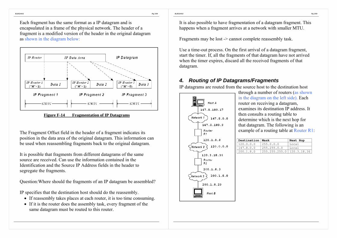
ELEC2402 Pg 249
Each fragment has the same format as a IP datagram and isencapsulated in a frame of the physical network. The header of afragment is a modified version of the header in the original datagramas shown in the diagram below:
Figure F-14 Fragmentation of IP Datagrams
The Fragment Offset field in the header of a fragment indicates itsposition in the data area of the original datagram. This information canbe used when reassembling fragments back to the original datagram.
It is possible that fragments from different datagrams of the samesource are received. Can use the information contained in theIdentification and the Source IP Address fields in the header tosegregate the fragments.
Question:Where should the fragments of an IP datagram be assembled?
IP specifies that the destination host should do the reassembly.• If reassembly takes places at each router, it is too time consuming.• If it is the router does the assembly task, every fragment of the
same datagram must be routed to this router.
ELEC2402 Pg 250
It is also possible to have fragmentation of a datagram fragment. Thishappens when a fragment arrives at a network with smaller MTU.
Fragments may be lost -> cannot complete reassembly task.
Use a time-out process. On the first arrival of a datagram fragment,start the timer. If, all the fragments of that datagram have not arrivedwhen the timer expires, discard all the received fragments of thatdatagram.
4. Routing of IP Datagrams/FragmentsIP datagrams are routed from the source host to the destination host
through a number of routers (as shownin the diagram on the left side). Eachrouter on receiving a datagram,examines its destination IP address. Itthen consults a routing table todetermine which is the next hop forthat datagram. The following is anexample of a routing table at Router R1:
Destination Mask Next Hop120.0.0.0 255.0.0.0 Local147.8.0.0 255.255.0.0 Local200.1.8.0 255.255.255.0 120.3.18.36

ELEC2402 Pg 251
The router obtains the destination address, D from the header. It usesthe mask field in the table entry to extract the prefix (network part) ofthe address and then compare the masking result with the destinationfield. If matched, routes according to the corresponding next hop field.
If ((Mask[I] & D) = Destination[i])then forward (NextHop[I])else next_entry;
Obviously the mask for Class A is 255.0.0.0; that of Class b is255.255.0.0 and that for Class C is 255.255.255.0.
Datagrams are routed on a “best-effort” basis. There is no guaranteethat datagrams will not be duplicated, corrupted, lost or delivered out-of-order.
ELEC2402 Pg 252
IPv6IPv4 as described above has certain limitations.
• The size of an IP addresses is limited to 32 bits, although it soundlarge. However this address has to be shared between networkand host identities. New applications use TCP.IP and need toassign IP addresses. E.g. cable TC receivers, point-of-saleterminals,…)
• IPv4 does not support new applications requiring real-timedelivery of audio and video information.
IP-The Next Generation IPng was introduced as IPv6 to overcomethese problems.

ELEC2402 Pg 253
Enhancement of IPv6• Use 128-bit IP addresses ->296 unique addresses.
Should be sufficient for a long, long time.• Option headers are put after the 40-octet mandatory header. Most
routers would not process these option headers.• Dynamic assignment of IPv6 addresses.• Addressing scheme support s anycast (i.e. to just one node in a
set of nodes) and multicast enhancement.• Can label a datagram belonging to certain traffic flow.
Figure F-15 The IPv6 fixed header (required).
Figure F-16 IPv6 mandatory header.
ELEC2402 Pg 254
A IPv6 contains a mandatory header as in Figure F-15 (known as IPv6Base Header), one or more Extension Headers as in Figure F-16 (forspecifying options) and the data area.
The description of the fields of mandatory header are listed as follows:
Version: Version number of the IP protocol (6).Traffic Class: Priority classes.Flow label: For those datagrams requiring special
handling within a network. (e.g. real-timeaudio or video)
Payload length: Length of the datagram excluding themandatory header.
Next Header: Identifies the type of extension header afterthe IPv6 header.
Hop Limit: A simplified TTL. Instead of counting thetime, specifies the number of hops that thedatagram can travel.
Source IPAddress:
IP address of the sender.
Destination IPAddress:
IP address of the destination.

ELEC2402 Pg 255
Unlike IPv4, IPv6 does not have fragmentation information in theheader. This is put into an extension header (Fragment header). Theconcept of the fragmentation process is shown as followings:
Figure F-17 The IPv6 Fragmentation
In IPv6, it is the source host, which is responsible for fragmentation,not the routers. This will reduce the workload on the routers, whichbecome critical when Internet grows larger and larger.
A host sends datagram of various sizes to discover the minimum MTUalong the path (i.e. the path MTU). This discovery is an iterativelearning process.
On top of unicast and multicast, IPv6 has an addition address type.• Anycast (cluster): The address is a set of hosts in the same
network (i.e. sharing a common prefix). The datagram will besent to the host, which is nearest to the sender.
ELEC2402 Pg 256
IPv6 uses IP addresses of 128 bits long. Even the dotted decimal formis difficult to read at this length. Use colon hexadecimal notation,known as colon hex.
An IPv6 address is divided into groups of 16 bits. Each group iswritten in hexadecimal form.
e.g. 68AE:281B:1F:0:0:7086:0:1234
Can use zero compression by throwing away a group with 0 as itsvalue. The above example becomes:
68AE:281B:1F:::7086::1234
0 compression is useful:• To make IPv6 addressing compatible with IPv4, any address
starts with 96 bits of 0 will be taken as a IPv4 address. With 0compression, it is easier to express IPv4 address.
• It is expected that many addresses contain many 0s when start todeploy IPv6.

ELEC2402 Pg 257
5. Internet Control Message Protocol (ICMP)
Although IP offers a connectionless service on a “best effect” basis, arouter reports to the source host the network error conditions that adatagram has encountered. The reporting protocol used in TCP/IP isInternet Control Message Protocol (ICMP) and the network conditionsto be reported are:
(i) Source quenchWhen a router runs out of buffers, it starts to discard incoming IPdatagrams. On discarding a datagram, the router sends a ICMPsource quench message to the source host. On receiving thismessage, a source host reduces the rate of issuing datagrams.(Flow control).
(ii) Time exceededThere are two timing operations:
• TTL timeout• Reassembly timeout
A ICMP time exceed message is sent to the source host reportingone of these situations.
(iii) Destination unreachableWhen a router discovers that a datagram cannot be delivered toits final destination, it sends a ICMP destination unreachablemessage to the source host to indicate whether unreachability isdue to the destined network or due to the destined host.
ELEC2402 Pg 258
(iv) RedirectWhen a router receives a datagram from a host, it checks whetherit is the appropriate router for the datagram. If not, it sends aICMP redirect message to the host indicating a change of thedestined host or a change of the destined network. The host thenadjusts the route accordingly.
(v) Fragmentation requiredWhen a router finds that fragmentation is required but the Don’tFragment” bit in the IP header is set, it discards the datagram andsends a ICMP fragmentation required message to the source host.
ICMP also specifies the following information messages:(vi) Echo Request/Reply
A host sends a ICMP echo request message. The destined hostreturns ICMP echo reply message.
(vii) Address Mask Request/ReplyA host broadcasts a ICMP Address Mask Request messageduring boot-up phase. A router receiving this message returns areply containing the 32 bits subnet mask for the network attachedto it.
(viii)Time stamp request/replySame as echo request/reply, but with timestamp.

ELEC2402 Pg 259
Although functionally ICMP is in the Internet layer, a ICMP messageis encapsulated in a IP datagram (i.e. a user of IP) as shown below:
ICMPHeader
ICMPMessage
: :IPHeader
IPDatagram
: :FrameHeader
NetworkFrame
Figure F-18 ICMP Message Encapsulation.
When a IP datagram carrying a ICMP message causes an error, it willnot be reported.
ICMP is used by some tools for various purposes. e.g.
• Ping (Packet InteNet Groper)This program sends a ICMP echo request message to a destinedhost to test its reachability.
• TracerouteThis program sends a series of probing datagrams to a destinedhost. The first datagram has its TTL set to 1. The first routerhaving decremented TTL to 0, sends a ICMP time exceededmessage to the source host. Therefore, can discover the identityof the first router. By sending out datagrams with a progressivevalues of TTL, the source host may discover the route to thedestination.Potential problems with this program are:
• Datagram loss and duplicated responses;• Dynamic routing of datagrams.
ELEC2402 Pg 260
Can also use ICMP to find the network MTU. Send a probingdatagram with “Don’t Fragment” bit set. If the datagram is too largerfor a router along the path, that router sends the “ICMP fragmentationrequired” message to the source host. The host then sends a datagramwith a shorter length. In this way, a host can discover the networkMTU. This method has the same problems as traceroute. Thereforethese applications are suitable for stable routes.
6. Internet MulticastingMulticast allows a host to send a datagram to more than one host.Unlike broadcasting, a host can decide whether to take part in amulticast.
Simplest way: Use unicast network to emulate multicast network.Sender sends a separate copy to each recipient. -> Inefficient.
Provide explicit support of multicasting at the network level. Thesender sends only a copy of datagram, which is replicated at a networkrouter (with multicast capability), which has multiple outgoing links toreach the recipients.
Multicast hardware reserves a large set of addresses for multicast.When a group of hosts wants to participate in multicast, they select amulticast address to communicate and thus become members themulticast group. The member hosts need to configure their networkinterface hardware to recognize the selected multicast address.
e.g. Ethernet support multicast.

ELEC2402 Pg 261
IP multicasting allows a multicast group to span over the Internet. IPmulticast membership is dynamic. A host can join or leave at will andit can become member of more than one group, In addition, a hostmay be allowed to send datagrams to a multicast group withoutbecoming a member first.
IP uses Class D addresses for multicasting. The group address field ina multicast datagram specifies a particular multicast group. Eachmember of the group receives a copy of the multicast datagram.
Routers that support multicast are called multicast routers whichforward multicast datagrams.
When a multicast router receives a multicast datagram and finds thatone or more of its local hosts are members of the multicast group, itensures that each local member host receives a copy of the datagram.If the local network has multicast hardware support, this distributionof the multicast datagram is carried out by the multicast hardware;otherwise, the router has to duplicate the multicast datagram and senda copy to each local member host.
Therefore, a multicast router has to maintain information on the groupmemberships of all the local hosts. When a host joins a group, it mustinform its local multicast router about this new membership, themulticast router then passes the membership information to othermulticast routers. In this way, the membership information propagatesover the Internet, However multicast router has to poll each local hostperiodically to check its group membership status becausemembership can be changed dynamically.
ELEC2402 Pg 262
To reduce traffic, a multicast router with hardware support does notneed to keep the precise group membership information of all its localhosts. The outer only needs to know whether there is at least a localhost still being an active member of a particular group. After receivinga multicast poll message, all the hosts that are active group memberswill delay their responses for a random period. Responses are sent bymeans of the multicast hardware. Therefore, all active member hostscan receive the earliest response and thus cancel their responses.
Internet Group Management Protocol IGMP is used by hosts and theirlocal multicast routers to exchange membership information.
IGMP (RFC 1112) is similar to ICMP as shown in Figure F-19. AIGMP message is encapsulated in a IP datagram.
Version: Version number of IGMPType: Query from a multicast router or response from a
host.Checksum: This is calculated with the same algorithm used for
a IP datagramGroupaddress:
Reported membership in a multicast group.
Figure F-19 The IGMP protocol.

ELEC2402 Pg 263
Integrated Services Architecture and RSVPRouting for multicast networks requires a different set of protocols,some of which are extensions from their unicast counterparts. e.g.Distance Vector Multicast Routing Protocol (DVMRP), MulticastOpen Shortest Path First (MOSPF).
Integrated Service Architecture (ISAA) supports real-time as well asnon-real-time services in a network (unicast or multicast). In order tosupport real-time applications (e.g. real-time voice, videoconferencing) in Internet, it is necessary to provide QOS (bandwidthand delay) guarantees. A signaling protocol is needed to allowreservation of resources (bandwidth) in the network. ResourcereSerVation Protocols (RSVP) can be used for this purpose. RSVPsupports network bandwidth reservation in multicast and it is receiver-oriented. Since unicast network can be considered as a degeneratecase of multicast, RSVP can also be used for unicast networks.
ELEC2402 Pg 264
In RSVP, QOS will be guaranteed in a session during which there is atraffic stream (known as “flow”) sent from a source to one or morereceivers. However, it is the receiver, which initiates resourcereservation. Consider the situation that the receivers are heterogeneous.Some can receive at highrates and some at lower rates (e.g. 24kbps,128kbps and 6Mbps as shown in the following diagram).
Figure F-20 Multicast at different bandwidth across networks.
A video server multicasts a video session to these heterogeneousreceivers. Should the video signal be coded into the lowest bit rate sothat every receiver can watch it (some watch a video of quality poorerthan they should)? Or should it be coded at the highest bit rate so thatsome can see good quality video (while others cannot see anything atall)? One way to solve this problem is to use “layering”. The signal isencoded into two or more layers. In the example, the video signal canbe encoded into three layers: layer 1 at 24kbps, layer 2 at 100 kbpsand layer 3 at 5 Mbps. The coding is done in such a way that layer 1on its own can be viewed by Client 4 (24kbps QOS). Layer 1 togetherwith layer 2 can be viewed by Client 3 (128 kbps QOS) at a better

ELEC2402 Pg 265
quality level. Similarly, Layers 1, 2 and 3 can be viewed by Clients 1and 2 (6 Mbps QOS) at an even better quality level.
With heterogeneous receivers, it is more convenient for the receiversto make reservation; otherwise, the sender has to keep the QOSinformation of each receiver even if it does not involve in theforthcoming session.
In RSVP, every client sends a reservation message (flow descriptor) toits upstream router, specifying the desired QOS and the set of packetsto receive in a session. On receiving a reservation message , a routerallocates its resources and adjusts its packet scheduler to meet therequest. It then in turn sends a reservation message to the nextupstream router. Reservations received by a router are merged.
e.g. Router C merges the reservations from D (128 Kbps) and E(6Mbps) into a reservation of 6 <bps. RSVP allows backtracking ofreservations. The server sends the video downstream at the reservedrate. The downstream routers deliver the video signal to the clients atthe reserved rates.
Note that RSVP is not a routing protocol. The rouging tree to areceiver from the sender must be constructed by the applying thechosen routing algorithm. RSVP at the source sends a path messagedownstream through the network to each recover along the computedrouting tree. In this way, the routers along the path know how toforward a reservation message from a receiver in the reverseddirection. Path messages will also be sent if there is any change ofroutes.
ELEC2402 Pg 266
Each router and the source keep each reservation and its pathinformation in a state. This state is called a soft state because it hasonly limited lifetime, which is dictated by a reservation timer. If areceiver wants to keep a reservation, it must periodically refresh thereservation by sending reservation messages. Similarly, the sendermust also periodically send the path messages. This arrangement canhelp to release unwanted reservation.
The major problem with RSVP is scalability. As Internet grows, real-time multicast communications increases. Routers have to maintainlarge number of soft states. There will also be a large number of pathmessages and reservation messages. It will be more difficult toguarantee QOS. RSVP will become very complicated and thereforeless efficient.
-> simpler, easy-to-implement and less-overhead protocols.
Instead of guaranteeing QOS, use the concept of Class of Services(COS). Each packet carries an identifier indicating its request serviceclass. A router on receiving a packet, schedules the packet andallocates resources according to the class of that packet. While RSVPhas an unknown number of QOS requirements, COS mechanismoffers only a limited number of classes. RSVP guarantees QOSclosely while COS only guarantees that packets with higher priority(according to their classes) are services better. Packets from real-timeservices have higher priorities. Therefore, as long as there is enoughbandwidth allocated to packets of higher classes, real-time trafficexperiences little congestion.

ELEC2402 Pg 267
7. Transport Protocol: TCP and UDPThe transport layer in TCP/IP protocol stack offers both connection-oriented and connectionless services.
Connection-oriented servicesTransmission control protocol TCP
Connectionless servicesUse datagram protocol UDP
7.1 TCP Connection-orient serviceTCP uses the unreliable connectionless IP datagram services toprovide reliable transport layer connection services.
Programmer: read and write data assuming reliability
Communication: unreliable IP datagram service
Therefore, need to provide a reliable data transport service toapplication program.
TCP, which is an end-to-end transport protocol, providing avirtual connection directly from an application on a computer toan application in another computer. The virtual connection isprovided by software at both ends using IP to exchange messages.
In many systems, an AP obtains TCP service by creating sockets (endpoints) at both the sending and receiving ends. Each socket at a hostmust be bound with a socket address, composed of the IP address ofthat host and the port number of the AP. A socket may have multipleconnections.
ELEC2402 Pg 268
The major features of TCP services are:• Reliable point-to-point connection
Three phases: Connect, data transfer and close.Each connection has exactly two end points. No corruption, loss,duplication nor out-of –order.
• Full duplex: Simultaneous transmission in both directions
• Stream interfaceEach TCP connection is a byte (octet) stream, not a messagestream. As a sending AP passes a message to a TCP connection,this message may be buffered or transmitted immediately in asingle or multiple TCP data units, called segments. The messagemay be merged with previous data, which have been buffered butnot yet transmitted. That is, message boundaries are notidentifiable in a TCP connection.
• Pushed dataA sending AP can use the TCP push function to request TCP totransmit data immediately
• Urgent dataA sending AP can use TCP urgent function to pass data urgently.TCP transmits the urgent data together with any buffered dataimmediately. The receiving AP is interrupted. It then reads thedata stream to extract the urgent data.
• Reliable connection startupThere should be no leftover from the previous connections.
• Graceful connection shutdownDeliver all data reliably before shutting down a connection onrequest.

ELEC2402 Pg 269
Format of TCP Segments:
Figure F-21 The TCP header.
Source Port: Source TCP userDestination Port: Destination TCP useSequence Number:(c.f. send sequencenumber in HDLC)
When the SYN bit is not set, it is the sequencenumber of the first octet in the data field.When the SYN bit is set, it is the initial sequencenumber ISN of the segment and the first octet in thedata field has a sequence number of (ISN+1 ).
Acknowledgementnumber:(c.f. receivesequence number inHDLC)
This is a piggyback acknowledgement, used toindicate the expected sequence number of the nextdata octet. It acknowledges all the data octets withsequence number up to and including one less thisnumber.
Head Length: The length of the header in multiple of 4 octets.Code bits (Flags):‧URG: Urgent pointer field in use‧ACK: Acknowledgement field in use
ELEC2402 Pg 270
‧PSH: Push function. This is used to request the receiver todeliver the data to the AP upon arrival.
‧RST: Reset the connection‧SYN: Synchronize the sequence number (connect)‧FIN: No more data from sender (finish, disconnect)Window: Flow control credit allocation in octets. This number
is used to indicate how many data octets a TCPsource is allowed to send to the TCP destination.
Checksum: It is calculated in a way similar to IP. It covers theheader, data and a pseudo-header.
Urgent pointer: Serves as an octet offset from the current sequencenumber at which the urgent data (out-of-bound) canbe found.
Options & padding: Specifies the options.

ELEC2402 Pg 271
There is a pseudo-header with fields coming from the IP header plusthe TCP segment length field as shown below:
Figure F-22 The pseudo-header included in the TCP checksum.
At the sending end, the pseudo-header is formed and pretended to thesegment (segment = the whole TCP packet to be sent with checksuminitial to zero). A padding field of 0’s may be appended to turn thesegment into a multiple of 2 octets. The checksum is computed overthe entire result.
Including the pseudoheader in the TCP checksum computation helpsdetect misdelivered packets, but including it also violates the protocolhierarchy since the IP address in it belong to the IP layer, not to theTPC layer.
However, the pseudo-header and the padding 0’s are not transmitted.At the receiving end, the pseudo-header and padding are formed andthe checksum is computed in the same manner.
Therefore, if the received and computed checksum agree, it is believedthat the segment is delivered to the intended host and port.
Not all segments sent across a connection will be of the same size. Butboth ends must agree on a maximum segment size (MSS). The
ELEC2402 Pg 272
Options field is used to negotiate for MSS. If the whole connection isin a single physical network. In general set MSS to the MTU of thenetwork. The default MSS is set to 536 octets. This is obtained bysubtracting the standard IP header size (20 octets) and TCP headersize (20 octets) from the default IP datagram size (576 octets).
7.2 Three-way handshaking for TCP connectionTCP uses a three-way handshaking arrangement to secure reliableconnection establishment (as shown in Figure F-23) and termination.A TCP segment with the SYN bit set is called a SYN segment, withthe ACK bit set, a ACK segment and with the FIN bit set a FINsegment.TCP uses a SYN segment to establish a connection.TCP uses a sliding window to control transmission. However thesliding window operates at the data octet level not at the segment level.Note that the sequence numbers at both ends (says, Host 1 and Host 2)do not start from the same value, say 0.
Figure F-23 Normal operation of three-way handshake. (CR denotesCONNECTION REQUEST = SYN bit set)

ELEC2402 Pg 273
In fact, Host 1 and Host 2 can choose different convenient values assequence numbers to start the connection. The three-way shaking andthe sequence number arrangement can handle the following twosituations correctly.
Case 1 Host 2 receives an old duplication of connection requestsegment from Host 1:
Case 2 There is an old duplicated connection request segment fromHost 1. Host 2 sends Ack and then there is an old duplicatedconnection acknowledge segment from Host 1:
ELEC2402 Pg 274
When a server receives a SYN segment to establish a connection, itreplies with a ACK packet and enters into the “connection half-open”state, waiting for confirmation. As a result, resources are consumed. Ifthere are too many connection request SYN segments received over ashort time (e.g. from a disguised hacker), there will be too many half-open connections. The resources in the server may be exhausted andno more connection requests can be accepted. When an open systemlike Internet, it is difficult to resolve attacks. There are ways to reducethe problem. e.g. randomly dropping half-open connections from thequeue and thus allowing genuine request to have a chance.
Connection TerminationTCP uses a FIN segment to terminate a connection as shown below.

ELEC2402 Pg 275
Can use the RST segment to abruptly terminating connection in bothdirections.
There are some special conditions regarding connection termination:
• Due to various reasons (e.g. the last FIN and ACK segments arerepeatedly lost, host crash), it is possible to have “half-open”connection. That is, one direction is disconnected but the otherdirection is not. Can have a “keepalive” timer. If there is noactivity on a connection for a long time, check the other end if itis still alive. If there is no response, terminate the connection.
• After closing a connection, TCP enters into a Timed Wait state. Itremains in this state for twice the maximum segment lifetime.This is to make sure that leftover segments from the closedconnection will die and therefore will not disturb the newconnection.
ELEC2402 Pg 276
TCP: Transmission of DataTCP uses a sliding window with variable length to controltransmission (flow control).
The following example illustrates the transmission procedure of TCP.Assume that a connection has already been made. The send sequencenumber starts at 0. Initially the receiver has a 4k buffer and thisinformation has been conveyed to the sender.
Figure F-24 Window management in TCP.

ELEC2402 Pg 277
When there is a change of buffer situation, the receiver advertises thenew window size to the sender. The sender transmits according to thenew window size. When the window size drops to 0, the sender stopstransmission except under the following conditions:
• May send urgent datae.g. use telnet to send a Unix command to a remote computerstarting a long process. Can use the key combination “CTRL-C”to terminate the process. Send this as urgent data.
• May send one byte to cause the receiver to re-advertise thewindow size and the next octet to receive. This is used to handledeadlocks due to the loss of window announcement.
Consider the following two situations:(i) The application supplies data to the sending TCP very slowly,
say a character at a time (e.g. Telnet).Each TCP segment from the sender carries only an octet of data.
TCP segment of 21 octets -> IP datagram of 41 octets.The receiver acknowledges the arrival of data.
TCP segment of 20 octets -> IP datagram of 40 octets.
When this octet of data has been consumed (, say by an editor),the receiver advertises the new window size.
TCP segment of 20 octets -> IP datagram of 40 octets.After processing the data, the editor echoes back.
TCP segment of 20 octets -> IP datagram of 40 octets.
Therefore, it takes 161 octets to complete the transmission ofonly one octet of data.
Efficiency=1/161=0.62% (extremely low)
ELEC2402 Pg 278
(ii) The application consumes data from the receiving TCP veryslowing, say a character at a time. This is the reverse of theprevious example but the consequence is the same. The buffer atthe receiving end runs out quickly (fast sending but slowconsumption). Eventually this reduces the window mechanism toa “stop-and-wait” situation. This is known as the Silly Syndrome.Can use a similar approach as in the previous example to analyzethe efficiency of this scenario.
The problem of the above situations can be reduced by:• Prevent the receiver from sending window update for a low
number of octets.• Wait until the window size reaches a certain size (e.g. half the
buffer size) and then advertise it to the sender.• Accumulate enough data at the sender before sending to the
receiver. e.g. When the first octet arrives at the sending TCP,send it. Do not send the subsequent octets until half of thewindow size or of the maximum segment size is reached, orwhen acknowledgement for the first octet comes.

ELEC2402 Pg 279
7.3 Congestion control at Transport LayerCan use the concept of window to achieve end-to-end flow control.The mechanism is similar to that in data link layer.
Problem: optimal window size depends on the bottleneck service ratealong the path and the round-trip time (RTT), which is thetime to send a packet to a destination node and receive areply from that node. In addition, these factors vary fromconnection to connection. Therefore use dynamic windowsize.
DECbit Scheme:
Figure F-25DECbit scheme.
In each packet header, there is a congestion-indication bit, which is setby an intermediate node experiencing congestion. When thedestination node issues an acknowledgement for packet, it copies thecongestion indication bit of the packet into the header of anacknowledgement packet.
ELEC2402 Pg 280
On receiving an acknowledgement, the source node inspects thiscongestion-indication bit and adjusts the transmission window size inthe following manner.
The source increases the window size until the bottleneck nodebecomes congested. Then it starts to receive acknowledgement withthe congestion-indicator set. It then reverts to reduce the window sizeuntil the congestion disappears. In this way, at equilibrium the sourcewindow size oscillates around the optimal value.
Can use implicit indication of congestion instead of including anexplicit congestion-indicator in a packet header. A source node keepson increasing the window size until there is re-transmission (whichmay be taken as an indication of data loss due to congestion). Then itstarts to reduce the window size and the cycle repeats.

ELEC2402 Pg 281
7.4 TCP congestion controlCan have a better way to increase and reduce the window size than asimple linear manner.
In TCP, the sender maintains a congestion window used to restrict theamount of data to be sent. The sender transmits data under therestriction of two windows: the advertised window from the receiverand the congested window.
A source node starts with 1 MSS (Maximum segment size) as thecongestion window size as shown in Figure F-26. Then increase thewindow size exponentially to a threshold value and then increaseslinearly beyond that threshold. The exponential phase is called the“slow-start” phase while the linear phase is called the “congestionavoidance” phase. The threshold is call the slow-start threshold,ssthresh which is initialized to half of the maximum allowablewindow size. On detecting a loss, ssthresh is set to half the currentwindow size and the window size is set to 1 MSS. Then the windowsize grows exponentially again up to the size of the receiver’s window.
Figure F-26An example of the Internet congestion algorithm
ELEC2402 Pg 282
Variants of this method are widely used in Internet (e.g. the Tahoealgorithm detects packet losses using timeouts.)
TCP uses sliding window of variable size for congestion control. Thedesign is based on an assumption that transmission is reliable.Therefore, packet loss is seldom due to transmission errors but largelydue to congestion at the host or at the network nodes. Therefore,detect congestion and adjust the issuing rate (slow down) according.
The TCP congestion control strategy runs into problem if theassumption is not true.e.g. In a wireless network, losses are largely due to transmissionproblem. Should try to re-transmit as quickly as possible on thedetection of a loss, not to slow down.

ELEC2402 Pg 283
TCP: timeoutA re-transmission timer is used to stop the “forever-waiting-for-acknowledgement” deadlock situation. But how long should the timerset for? It should be set according to the round-trip-time, RTT, whichis the time to send a packet to a destination node and receive a replyfrom that node. But RTT fluctuates according to traffic conditions.
Figure F-27 (a) Probability density of acknowledgement arrival timesin the data link layer. (b) Probability density of acknowledgement arrival
times for TCP.
ELEC2402 Pg 284
In data link, can set the timeout value around the high peak (i.e.20msec). Delay is quite is quite predictable for a point-to-pointconnection.
In TCP, RTT spreads over a wider range as shown in Figure F-27(b)rather than (a). This is because TCP has to deal with a wide diversityof underlying physical networks. It has to tolerate a wide range ofdelay, throughput and packet loss rate. Therefore RTT tends tofluctuate. In the above example, if set the timeout at 20 msec, therewould be quite a significant amount of unnecessary retransmission ofsegments as well as unnecessary long waiting intervals for lostsegments.
Compounding the problem further, the network traffic situation maychange rapidly making a static timeout algorithm ineffective.
Adjust the timeout values according to the network performance.
Maintain a variable RTT for each connection. RTT holds the bestcurrent estimate of the round-trip-time for the TCP connection. Onsending a segment, start a timer which is used both for measuring howlong an acknowledgement comes and for timeout operation for re-transmission. When the acknowledgement comes, adjust RTTaccording to the remaining value of the timer. The new timeout valueis set according to the calculated RTT.

ELEC2402 Pg 285
8. UDP Connectionless ServicesUDP allows AP to encapsulate data directly in IP datagrams and sendthemWithout establishing a connection beforehand. Essentially, UDP haslittle to do. It puts the port information in a header. Format of a UDP:
Figure F-28 The UDP header.
ELEC2402 Pg 286
9. Network applications
Figure F-29 A simple Client-Server Model of TCP/IP.
Network hardware and protocol software provides a communicationtransport base for application programs in different computers. Thereare at least two application programs involving in a communication.One initiates the communication actively while the other one waitspassively. -> Client-Server model as shown in Figure F-29.
An application program interacts with the communication protocolsoftware in an OS through a well-defined Application ProgramInterface (API) which defines a set of operations that an applicationcan perform in order to interact with the protocol software. In mostOS, the API is in the form of a set of procedures with parameters.Socket API is widely used. The socket API is provided either as OSprocedures (native sockets) or library procedures. A socket can beseen as a network communication end-point. An application mustrequest the OS to create a socket before communication can start. Thesystem then returns a descriptor to the application. However, this

ELEC2402 Pg 287
newly created socket does not have a local address. A server uses thebind procedure to obtain a local address (protocol port number) atwhich the server will wait for contact. The Berkeley Socketprocedures/primitives are shown in the following table.
Primitive Meaningsocket Creates a new socket (communication end point)close Terminate the use of the socket. Any connection on that socket
will be closed first.bind Server assigns a local address to an unbound socket.listen Server places a bound socket in the passive mode to wait for
clients to make connection request. It also specifies the requestquene size for this socket.
accept For connectionless service, server can accept messages from abound socket.For connection-oriented service, must listen to wait for aconnection request. If there is no request in the quene, theserver is blocked. If there is a request, a new socket is createdand the new descriptor is sent to the client that has made thatrequest. Use this socket for communication between the serverand that client. When the connection is closed, the server usesthe original socket to accept new connection request.
connect For connection-orient transport protocol, initiates a connectionat the transport level to a specified server which has calledaccept.For connectionless transport protocol, merely mark the socketas connected and note down the server address. Then no needto specify the destination address for each message.
send Send data over a connected socket.sendto Send data to an unconnected socket. The destination address is
also supplied,.sendmsg Send a structured message to an unconnected socket. The
message contains the destination address.recv Receive data from a connected socket.recvfrom Receive data from an unconnected socket. Source address of
the message is also obtained.recvmsg Receive a structured message from an unconnected socket.
This message contains the source address.
ELEC2402 Pg 288
close Release the connection
Applications can also use read and write to transfer data over aconnected socket. Therefore, to an application program, the socketAPI can be taken as an I/O interface. The socket API follows theconventional way of I/O access: open-read-write-close as shownbelow.
Figure F-30 A simple Client-Server Example.

ELEC2402 Pg 289
Section G
The Application Layer (Layer 7)
1. The Domain Name System
2. Electronic Mail
3. Multimedia
ELEC2402 Pg 290
The Application Layer (Layer 7)The layers below the application layer are there to provide reliabletransport, but they do not do real work for users.
Even in the application layer there is a need for support protocols, toallow the applications to function. Accordingly, we will look at one ofthese before starting with the applications themselves. The item inquestion is DNS, which handles naming within the Internet. After that,we will examine two real applications: electronic mail and multimedia.
1. The Domain Name System
Although programs theoretically could refer to hosts, mailboxes,and other resources by their network (e.g., IP) addresses, theseaddresses are hard for people to remember. Also sending e-mail toIP address means that if the ISP or organization moves the mailserver to a different machine with a different IP address, the e-mailaddress has to be changed ASCII names to decouple machine name from machineaddresses.
DNS (RFCs 1034 and 1035) – a hierarchical, domain-based namingscheme and a distributed database system for implementing themachine naming scheme.

ELEC2402 Pg 291
1.1 The DNS Name SpaceThe Internet is divided into over 200 top-level domains, whereeach domain covers many hosts. Each domain is partitioned intosub-domains, and these are further partitioned, and so on asshown in Figure G-1.
Figure G-1 A portion of the Internet domain name space.
Domain names are case insensitive, so edu, Edu and EDU meanthe same thing. Component names can be up to 63 characterslong, and full path name must not exceed 255 characters.
To create a new domain, permission is required of the domain inwhich it will be included. For example, if a VLSI group is startedat Yale and wants to know as vlsi.cs.yale.edu, it has to getpermission from whoever manages cs.yale.edu.
ELEC2402 Pg 292
1.2 Resource Records
Every domain, whether it is a single host or a top-level domain,can have a set of resource records associated. For a single host,the most common resource record is just its IP address, but manyother kinds of resource records also exist.
A resource record is a five-tuple. Although they are encoded inbinary for efficiency, in most expositions, resource records arepresented as ASCII text, one line per resource record. The formatis as follows:
Domain_name Time_to_live Class Type Value
Figure G-2 A portion of a possible DNS database for cs.vn.nl
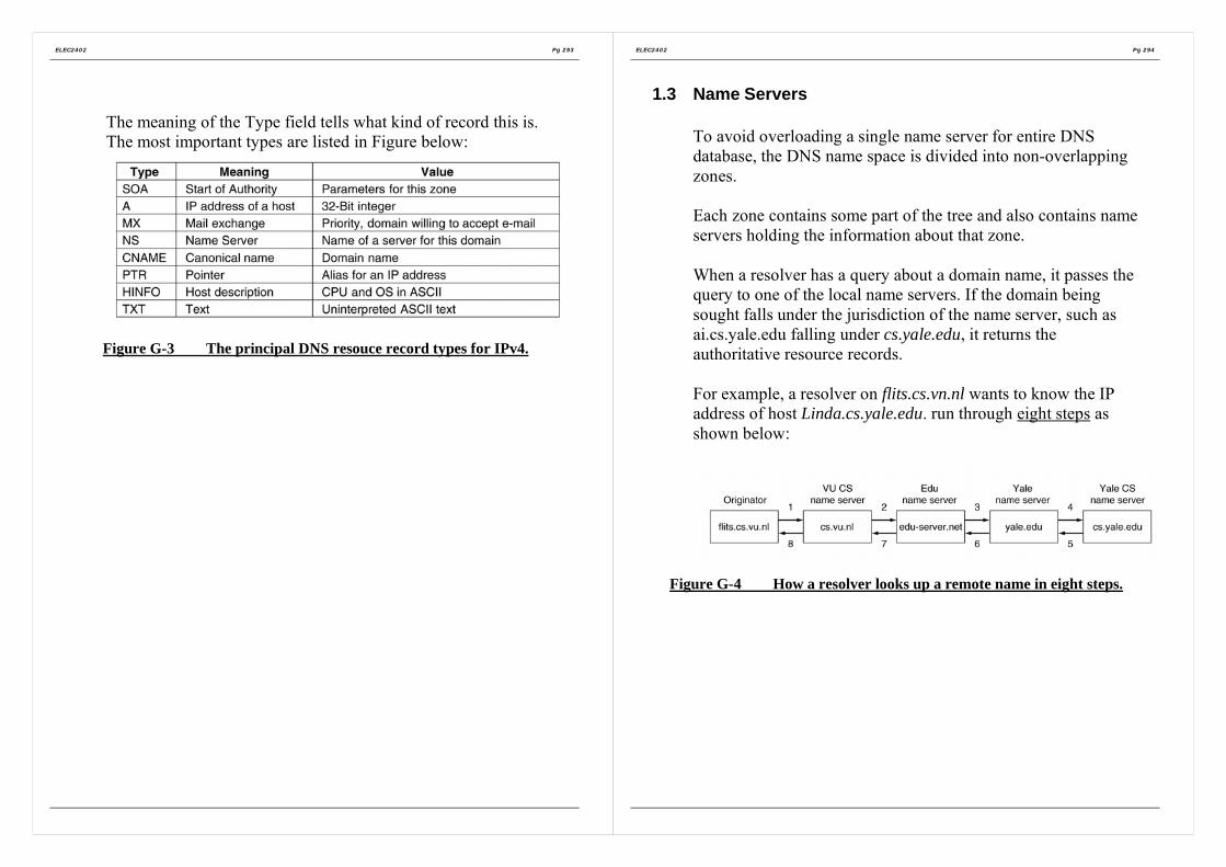
ELEC2402 Pg 293
The meaning of the Type field tells what kind of record this is.The most important types are listed in Figure below:
Figure G-3 The principal DNS resouce record types for IPv4.
ELEC2402 Pg 294
1.3 Name Servers
To avoid overloading a single name server for entire DNSdatabase, the DNS name space is divided into non-overlappingzones.
Each zone contains some part of the tree and also contains nameservers holding the information about that zone.
When a resolver has a query about a domain name, it passes thequery to one of the local name servers. If the domain beingsought falls under the jurisdiction of the name server, such asai.cs.yale.edu falling under cs.yale.edu, it returns theauthoritative resource records.
For example, a resolver on flits.cs.vn.nl wants to know the IPaddress of host Linda.cs.yale.edu. run through eight steps asshown below:
Figure G-4 How a resolver looks up a remote name in eight steps.

ELEC2402 Pg 295
2. Electronic Mail
2.1 Architecture and Services
Email system consist of two subsystems:(i) User Agents
User Agent is normally a program that accepts a variety ofcommands for composing, receiving, and replying tomessages, as well as for manipulating mailboxes.
(ii) Message Transfer agentsMove the messages from the source to destination.
2.2 Message Formats
(i) ASCII e-mail messages are defined in RFC 822.
Figure G-5 RFC 822 header fields related to message transport.
ELEC2402 Pg 296
Figure G-6 Some fields used in the RFC 822 message header.
(ii) MIME – The Multipurpose Internet Mail Extensions (RFCs2045-2049)
Defines encoding rules for non-ASCII messageswithout deviating from RFC 822, MIME message canbe sent using the existing mail programs and protocols.
2.3 Message Transfer
Within the Internet, e-mail is delivered by having the sourcemachine establish a TCP connection to port 25 of the destinationmachine. Listening to this port is an e-mail daemon that speaksSMTP (Simple Mail Transfer Protocol) which is a simple ASCIIprotocol.

ELEC2402 Pg 297
2.4 Final Delivery
Many people access the Internet by calling their ISP over amodem, if the connection breaks down, e-mail cannot send to theclient machine.=> a message transfer agent on ISP machine accepting e-mail
for its customers and store it in their mailboxes on an ISPmachine.
Two protocols are available:POP3 and IMAP.
Figure G-7 A comparison of POP3 and IMAP.
ELEC2402 Pg 298
3. Multimedia
3.1 Introduction to Digital Audio
The frequency range of human ear runs from 20 Hz to 20,000 Hz.Audio CDs are digital with a sampling rate of 44,100 samples/sec,enough to capture frequencies up to 22,050 Hz and the samplesare 16 bits which allow only 65,536 distinct values. To senduncompressed audio CDs over network requires 1.411 Mbps forstereo (almost a full T1 channel bandwidth).=> a compression method required.
3.2 Audio Compression
Popular one is MP3 (MPEG audio layer 3). Audio compression isdone in one of two ways. In waveform coding the signal istransformed mathematically by a Fourier transform into itsfrequency components. The other way, perceptual coding,exploits certain flaws in the human auditory system to encode asignal in such a way that it sounds the same to a human listener,even if it look quite different on an oscilloscope.
MP# can compress a stereo rock’n roll CD down to 96k bps withlittle perceptible loss in quality. For a piano concert, at least 128kbps re needed.
3.3 Streaming AudioThe actual transmission is usually with a protocol like RTP (areal-time protocols layered on top of UDP, so packets may belost.).

ELEC2402 Pg 299
The server is pushing the data to the client machine to reduceunnecessary data requests and the client plays the media throughthe client’s buffer rather than directly from the network.
Figure G-8 The media player buffers input from the media server andplays from the buffer rather than directly from the network.
ELEC2402 Pg 300
Section H
Network Security
1. Aspects of network security
2. Encryption
3. Digital signature
4. Authentication protocols
5. E-Mail Security
6. Web Security
7. Packet filtering and firewall

ELEC2402 Pg 301
1. Aspects of network security• Data integrity
Received data = transmitted data?Checksum or CRC; but not 100%
• Data availabilityProtection against illegal access to dataSimple password may not work due to eavesdropping orwiretapping.Masquerading:
Replace the original message sequence with new messagesequence
• Data confidentiality and privacyProtection against unauthorized access.Encode data with special algorithm such that only the receivercan decode it.-> Cryptography:
encryption/decryption (encipherment/decipherment).
ELEC2402 Pg 302
2. Encryption
Message before encryption is called plaintext and that after encryption,ciphertext. Most encryption methods put the encryption information ina encryption key which is known only to the sender and the recipient.
Figure H-1 The encryption model (for a symmetric-key cipher)
Three basic encryption techniques
(i) SubstituteReplace a plaintext alphabet with another alphabet according tocertain rule.e.g. simple shifting by places. (encryption key = 2)
Plain text: computer networkCiphertext: eqorwvgt”pgvyqtm
If the number of alphabets is n, the number of possible keys(including no shift) is n. very easy to crack.

ELEC2402 Pg 303
Can use a more complicated scheme, e.g. use a random mix ofthe plaintext alphabet. Then there are n! possible keys. Still quiteeasy to crack. Can look for some frequent groups of informationaccording to statistics.
If the plaintext is in plain English, can look for the mostfrequency used letters (a,o), 2-letter combinations (in, th) or 3-letter combinations (the, and),…
(ii) TransposeReorder the information (alphabet) in a plaintext.e.g. Divide the plaintext into groups of n characters. Theciphertext is formed by first taking all the first characters in eachgroup, then all the second characters,…
Encryption key=4Plaintext: computer networkCiphertext: cu wotnomeerprtk
Same problem as the substitution method.
ELEC2402 Pg 304
(iii) One-Time PadsThis technique has been known for decades. First choose a trulyrandom (not pseudo random) bit string as the key. Then convertthe plaintext into a bit string, for example by using its ASCIIrepresentation. Finally, compute the XOR (exclusive OR) ofthese two strings, bit by bit. The resulting ciphertext cannotbroken, because in a sufficiently large sample of ciphertext, eachletter will occur equally often, as will every digram, every ingram,and so on. (Disadvantage: In order to send k amount of data, youneed a key with length k.)
Figure H-2 The use of a one-time pad for encryption and thepossibility of getting any possible plaintext from the ciphertext by the use
of some other pad.
Most encryption systems uses product cipher method which is acombination of the above first two techniques working at the bit level.e.g. Data Encryption Standard (DES) which is a block cipher. DESworks on blocks of 64 bits with 56-bit encryption key.
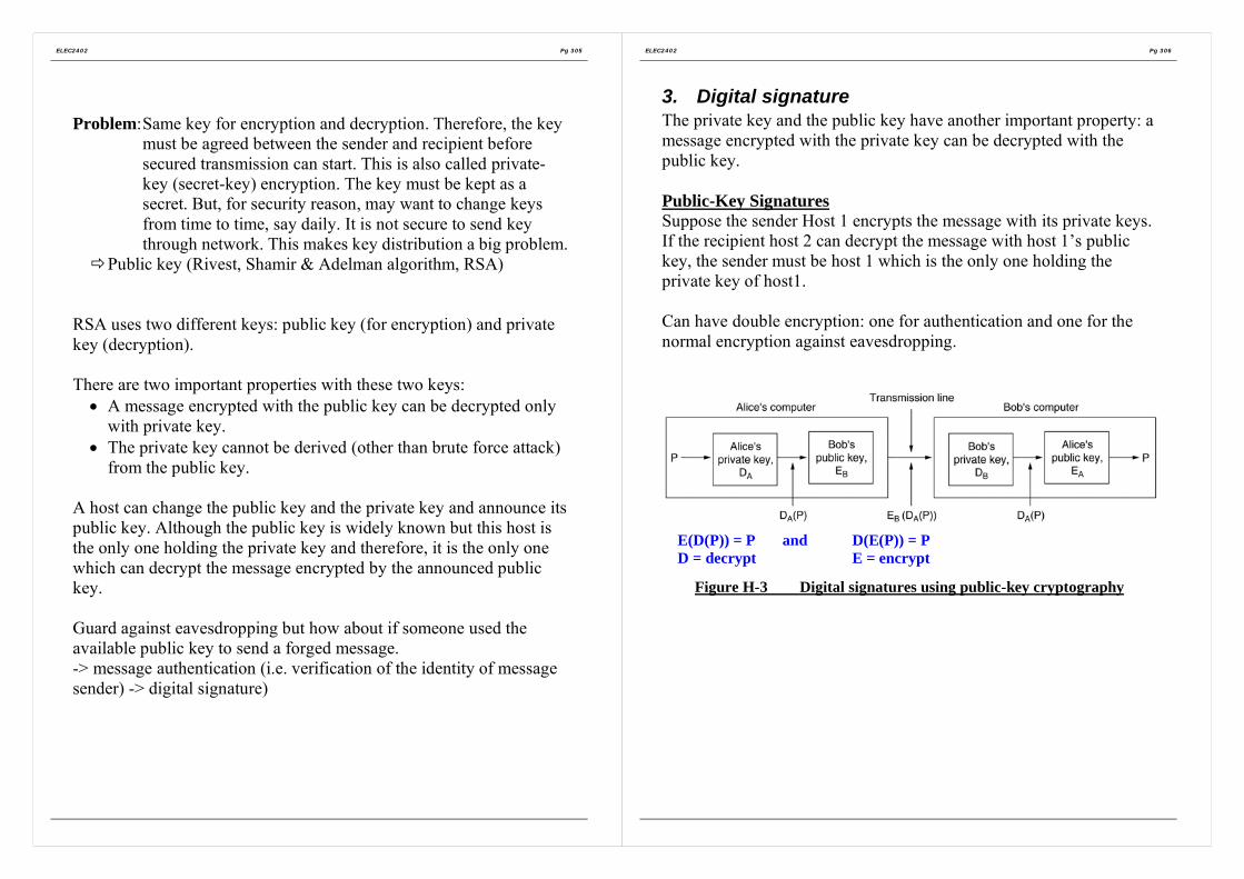
ELEC2402 Pg 305
Problem:Same key for encryption and decryption. Therefore, the keymust be agreed between the sender and recipient beforesecured transmission can start. This is also called private-key (secret-key) encryption. The key must be kept as asecret. But, for security reason, may want to change keysfrom time to time, say daily. It is not secure to send keythrough network. This makes key distribution a big problem.
Public key (Rivest, Shamir & Adelman algorithm, RSA)
RSA uses two different keys: public key (for encryption) and privatekey (decryption).
There are two important properties with these two keys:• A message encrypted with the public key can be decrypted only
with private key.• The private key cannot be derived (other than brute force attack)
from the public key.
A host can change the public key and the private key and announce itspublic key. Although the public key is widely known but this host isthe only one holding the private key and therefore, it is the only onewhich can decrypt the message encrypted by the announced publickey.
Guard against eavesdropping but how about if someone used theavailable public key to send a forged message.-> message authentication (i.e. verification of the identity of messagesender) -> digital signature)
ELEC2402 Pg 306
3. Digital signatureThe private key and the public key have another important property: amessage encrypted with the private key can be decrypted with thepublic key.
Public-Key SignaturesSuppose the sender Host 1 encrypts the message with its private keys.If the recipient host 2 can decrypt the message with host 1’s publickey, the sender must be host 1 which is the only one holding theprivate key of host1.
Can have double encryption: one for authentication and one for thenormal encryption against eavesdropping.
Figure H-3 Digital signatures using public-key cryptography
E(D(P)) = P and D(E(P)) = PD = decrypt E = encrypt

ELEC2402 Pg 307
Encrypting the whole message for authentication is very time-consuming. Therefore, encrypt only a small message (e.g. amathematical function of the plaintext, e.g. CRC) with the private keyof the sender into a digital signature. The digital signature is thenappended as a trailer to the original plaintext. This is in an analogy ofhaving the sender “sign” the message and the recipient verifysignature.
Message Digests (to ensure messages do not alter by intruder)One criticism of signature methods is that they often couple twodistinct functions: authentication and secrecy. Often, authentication isneeded but secrecy is not. An authentication scheme that does notrequire encrypting the entire message called message digest isrequired.
This scheme is based on the idea of a one-way hash function that takesan arbitrarily long piece of plaintext and from it computes a fixedlength bit string. This hash function, MD, called a message digest, hasfour important properties:
Given plaintext P, it is easy to compute MD(P). Given MD(P), it is effectively impossible to find P. Given P no one can find P’ such that MD(P’)=MD(P).
(Cannot be achieve in practice - the birthday attack) A change to the input of even 1 bit produces a very
different output.Examples are MD5 and SHA-1 (Secure Hash Algorithm) algorithms.
Figure H-4 Use of SHA-1 and RSA for signing nonsecret messages
RSA = Rivest, Shamir,Adleman – the threediscoverers
ELEC2402 Pg 308
4. Authentication protocols
Key Distribution Centre (KDC) / Certificate Authority (CA)In e-commerce, may have a large number of clients and many serviceproviders. If a client needs a key for each service, e.g. one key for abank and another key for a supermarket, key management becomes aburden.
register with a trusted party (e.g. Post Office in HK) andget a key for each session of transactions with a service. Key Distribution Centre (KDC) / Certificate Authority
(CA)
Authentication using Kerberos(Kerberos = A multiheaded dog in Greek mythology that used to guard theentrance to Hades.)Kerberos is an authentication system commonly used in many realsystems (including Windows 2000). It does not use a public key but arandom session key for each session.
There are three parties involved:1) CA: the trusted party offering authentication service.2) Application server (S): offers an application service and is also
known as end server.3) Client (C): usually can be viewed as composed of a user (U) and
a workstation (WS) through which the user interacts with CA andS.

ELEC2402 Pg 309
Figure H-5 The operation of Kerberos V4.
In Kerberos, users and application servers must register with the CA.CA maintains a database containing the password of each user and theprivate key of each application server.
When a user request for service, it must first obtain a ticket from CAand presents this ticket to a server with proof that the ticket wasoriginally issued to the user (i.e. authentication). Kerberosauthentication protocols ensure that the service access operation isdone in a secured manner. There are three typical phases:
1) Client requests ticket from CA in order to access a service.2) CA issues ticket with session key for that service.3) Client requests the server for service with authentication and
session key.
There are two servers in the CA.1) Authentication server (AS)
Verifies users during login and allows it to access TGS.2) Ticket granting server (TGS)
Issues “proof of identity ticket” to allow a client to access the endserver.
ELEC2402 Pg 310
Note: since TGS provides a service of issuing tickets to users so thatthey can be authenticated to access services of the appropriate endservers. Therefore, TGS can also be accessed by means of the serviceaccess protocol.

ELEC2402 Pg 311
5. E-Mail Security
One example: PGP (Pretty Good Privacy):• Essentially the brainchild of one person, Phil Zimmermann.
• A complete e-mail security package that provides privacy,authentication, digital signatures, and compression, all in aneasy-to-use form.
• Encrypts data by using a block cipher called IDEA(International Data Encryption Algorithm), which uses 128-bitkeys.
• Complete package, including all the source code, is distributedfree of charge via the Internet and is widely used.
• Supports text compression, secrecy, and digital signatures.
ELEC2402 Pg 312
6. Web Security
6.1 SSL – The Secure Sockets Layer
When the Web burst into public view, it was initially used for justdistributing static pages. However, before long, some companies gotthe idea of using it for financial transactions, such as purchasingmerchandise by credit card, on-line banking, and electronic stocktrading. These applications created a demand for secure connections.
SSL builds a secure a secure connection between two sockets,including:
i. Parameter negotiation between client and server.ii. Mutual authentication of client and server.
iii. Secret communication.iv. Data integrity protection.
The positioning of SSL in the usual protocol stack is illustrated inFigure H-6 effectively, it is a new layer interposed between theapplication layer and the transport layer, accepting requests from thebrowser and sending them down to TCP for transmission to the server.
Figure H-6 Layers (and protocols) for a home user browsing with SSL.

ELEC2402 Pg 313
The SSL consists of two subprotocols, one for establishing aestablishing a secure connection and one for using it.
Below is how secure connections are established as illustrated inFigure H-7.
Figure H-7 A simplified version of the SSL connection establishmentsubprotocol.
ELEC2402 Pg 314
1. Alice sends a request to Bob to establish a connection,specifying the SSL version Alice has and her preferenceswith respect to compression and cryptographic algorithms.
2. Bob makes a choice among the various algorithms thatAlice can support and sends his own nonce, RB.
3. Bob sends a certificate containing his public key. If thiscertificate is not signed by some well-known authority, healso sends a chain of certificates that can be followed backto one. All browsers, including Alice’s, come preloadedwith about 100 public keys, so if Bob can establish a chainanchored at one of these, Alice will be able to verify Bob’spublic key. At this point Bob may send some othermessages (such as a request for Alice’s public-keycertificate)
4. When Bob is done. He sends message 4 to tell Alice it is herturn.
5. Alice responds by choosing a random 384-bit premaster keyand sending it to Bob encrypted with his public key. Theactual session key used for encrypting data is derived fromthe premaster key combined with both nonces in a complexway.
6. Alice tells Bob to switch to the new cipher.7. Alice finished with the establishment sub-protocol.8 and 9 Bob then acknowledges her.
However, although Alice knows who Bob is, Bob does not know whoAlice is (unless Alice has a public key and a corresponding certificatefor it, an unlikely situation for an individual). Therefore, Bob’s firstmessage may well be a request for Alice to log in using a previouslyestablished login name and password. The login protocol, however, isoutside the scope of SSL.

ELEC2402 Pg 315
For actual transport, a second subprotocol is used, as shown in FigureH-8.
Messages from the browser are first broken into units of up to 1KB. Ifcompression is enabled, each unit is then separately compressed. Afterthat, a secret key derived and premaster key is concatenated with thecompressed text and the result hashed with the agreed-on hashingalgorithm (usually MD5). This hash is appended to each fragment asthe MAC. The compressed fragment plus MAC is then encrypted withthe agreed-on symmetric encryption algorithm. Finally, a fragmentheader is attached and the fragment is transmitted over the TCPconnection.
Figure H-8 Data transmission using SSL.
ELEC2402 Pg 316
7. Packet filtering and firewall
Firewalls forced everyone entering or leaving the castle to passs overa single drawbridge, where they could be inspected by the I/O police.With networks, the same trick is possible: a company can have manyLANs connected in arbitrary ways, but all traffic to or rom thecompany is forced through an electronic drawbridge (firewall), asshown in Figure H-9.
The firewall in Figure H-9 has two components: two routers that dopacket filtering and an application gateway. Simpler configurationsalso exist, but the advantage of this design is that every packet musttransit two filters and an application gateway to go in or out. No otherroute exists.
In Figure H-9, most likely the packet filter on the inside LAN checksoutgoing packets and the one the outside LAN checks incomingpackets. Packets crossing the first hurdle go to the application gatewayfor further examination.
Figure H-9 A firewall consisting of two packet filers and anapplication gateway.

ELEC2402 Pg 317
Packet filters are typically driven by tables configured by the systemadministrator. These tables list sources and destinations that areacceptable, sources and destinations that are blocked, and default rulesabout what to do with packets coming from or going o other machines.
The second half of the firewall is the application gateway. Rather thanjust looking at raw packets, the gateway operates at the applicationlevel. a mail gateway, for example, can be set up to examine eachmessage going in or coming out and check if there is virus in the email.
ELEC2402 Pg 318
Section I
Example Networks
1. ISDN (Integrated Services Digital Network)
2. Asynchronous Transfer Mode (ATM)

ELEC2402 Pg 319
1. ISDN (Integrated Services Digital Network)
1.1 IntroductionTelephone system:
• For more than a century, the primary internationalcommunication infrastructure has been the telephone.
• It was designed for analog voice transmission and is inadequatefor modern communication need such as data transmission(interactive & non-interactive) facsimile, video and etc.,
• Thus, these demands lead to the development of a new advanceddigital system, the ISDN, to replace a major portion of theworldwide telephone system by early 21st century.
• The primary goal of ISDN is the integration of voice and non-voice services.
• ISDN is basically a redesign of the telephone system &coordinated by CCITT.
• The key ISDN recommendations were approved in 1984, withrefinements in 1988.
• Figure I-1 lists some of the key recommendation (Decina, 1986)
ELEC2402 Pg 320
Number Title1.120 Integrated Services Digital Networks (ISDN)1.210 Principles of telecommunication services supported by an
ISDN1.211 Bearer services supported by an ISDN1.310 ISDN network functional principles1.320 ISDN protocol reference manual1.411 ISDN user/network interfaces – reference configurations1.412 ISDN user/network interfaces – interface structure and
access1.420 Basic network/user interface1.421 Primary rate network/user access1.430 Basic user/network interface – Layer 1 specification1.431 Primary rate user/network interface – Layer 1 specification1.440 ISDN user/network interface Data Link Layer protocol –
general aspects1.441 ISDN user/network interface Data Link Layer specification1.450 ISDN user/network interface Layer 3 – general aspects1.451 ISDN user/network interface Layer 3 -specification
Figure I-1 Some of the principal CCITT ISDN Recommendations

ELEC2402 Pg 321
1.2 ISDN Services
=> voice / speech communication services:• additional enhanced features:e.g., - instant call setup,
- display the caller’s telephone number, name, andaddress on a display while ringing, or even the caller’sdatabase record to be displayed on screen.
- call transfer and forwarding to any number worldwide;conference call worldwide; capable of leavingmessages while the callee is absence; an automaticwakeup call service; etc.
=> data transmission services:• allow users to connect their ISDN terminal or computer to any
other one in the world. (at present, such connections arefrequently impossible internationally due to incompatiblenational telephone systems)
• capable of broadcasting message through the network to theclosed-user-group users or all the users.
• closed-user-group features acting as a private network, no callsfrom outside the group can come in (except in carefullycontrolled ways), and the member o group can only call othermembers of the group.Attractive to many corporate, government, diplomatic andmilitary agencies for privacy and security reasons.
ELEC2402 Pg 322
Videotex• Videotex is interactive access to a remote database by a person at
a terminal.• On-line telephone directory assistance, as to begin to abolish all
the telephone books and information operators (at enormoussavings) by providing each subscriber with a small terminal foraccessing the on-line telephone book.
• On-line yellow-page services:The complete process of purchasing: selecting a company,ordering products, invoicing, and charging can be done throughthe Videotex service. Other examples such as the airline, hotel &restaurant reservations, bank-by-terminal, and etc.
Teletex• Electronic mail• Facsimile (FAX)
Telemetry or alarm• gas and electricity meters reading (where only a few digits are
needed to be collected)• smoke and fire alarm detection• medical alarm• etc.

ELEC2402 Pg 323
1.3 Evolution of ISDNThere are currently three distinct system components which wouldhave a major influence on the ISDN evolution towards the final ISDN,as shown in the figure below.
Packetswitchingnetwork
Evolutionof ISDN
Public switched network(the telephone system)
CCIS network(Common ChannelInteroffice Signaling)
In-band signaling of the public switched network• The analog voice telephone system originally sent all its control
information in the same 4 kHz channel used by voice. Pure tonesat various frequencies were used for signaling by the systemitself; => i.e., in-band signaling.
• As a result, users could inter with the internal signaling systemby generating a sequence of appropriate tones. This leads toserious commercial and individual billing fraud.
• Solution: CCIS
ELEC2402 Pg 324
CCIS (Common Channel Interoffice Signaling)
• To eliminate the problems caused by in-band signaling, AT&Tbuilt and installed a packet switched network, the CCIS, separatefrom the main public switched network.
• CCIS runs at 2.4k bps, and it was designed to move the signalingtraffic out-of-band.
• With CCIS, when an end office needed to set up a call, it chose achannel on an out-going trunk of the public switched network.Then it sent a packet on the CCIS network to the next switchingoffice along the chosen route telling which channel had beenallocated. This CCIS node then chose the next outgoing trunkchannel, and reported it on the CCIS network.
• Thus, the management of the analog connections was done on aseparate packet switched network to which the users had noaccess.
• CCIS was then regarded as a great success, and was soon used bymore and more applications.The four major uses now are:
a) Call setup, routing and terminationb) Internal database access
e.g. verification of telephone credit and numbers.c) Network operations and support.
e.g. optimum route.d) Accounting and billing.

ELEC2402 Pg 325
The local loop has bandwidth of about 2Mbps for 80 % of the loopshorter than 7 or 8 km, and somewhat less on longer ones.
Packet switched network
packet networks
CCIS networkISDNExchange
ISDNExchange
Carrier’s equipment
ISDN Interface using twisted pairs
(a)
Customer’sequipment
ISDNTerminal
Customer’sequipment
ISDNTerminal
Integrated ISDN Transportnetwork
ISDNExchange
ISDNExchange
(b)
ISDNTerminal
ISDNTerminal
Figure I-2 (a) Initial stage of ISDN evolution. (b) Later stage.
ELEC2402 Pg 326
Packet switching network• For data transmission, such as remote database access.• Costs depend primarily on traffic volume, not the connect time.• Growth in use since the mid 1970 as the packet switching
networks are available commercially.
Thus, the current telephone system really has three distinctcomponents:
a) The analog public switched networkb) CCIS for controlling the voice networkc) Packet switching networks for data
In fact, the ISDN will thus be evolved from the current telephonesystem. This means that ISDN was designed from the beginning tolive with the limitation of the existing local loops and the voice, CCISand packet networks.
• The first step towards ISDN was to define and standardize theuser-to-ISDN interface.
• The next step was to slowly start replacing existing end officeswith ISDN exchanges that support the ISDN interface.As shown in Figure I-2(a), those users connected to an ISDNexchange can use ISDN services on call to other ISDN users,even though these calls use the facilities of the existing networks.
• Eventually, the existing transmission and switching networks willbe replaced by an integrated one, as shown in Figure I-2(b);which is expected to be completed by the 21st century.

ELEC2402 Pg 327
ISDNTerminal
ISDNAlarm
ISDNTelephone
Customer’s equipment
NT1Tocarrier’sinternalnetwork
ISDNExchange
Carrier’s equipment
T U
Digitalbitpipe
(a)
Customer’s office Carrier’s office
TE1ISDN
Terminal
NT1: network boundary
NT2: customer PBX
TE1: ISDN terminal
TE2: non-ISDN terminal
TA: terminal adapter
TA
Customer’s equipment
NT1Tocarrier’sinternalnetwork
ISDNExchange
Carrier’s equipment
T U
Digitalbitpipe
(B)
Customer’s office Carrier’s office
TE1ISDN
Telephone
LANGateway
NT2ISDNPBX
NonISDN
Terminal
RS
S
S
Figure I-3 (a) Example ISDN system for home use. (b) Example ISDNsystem with a PBX for use in large businesses.
CCITT has defined 4 reference points; R S T and U :U: the connection between the ISDN exchange and NT1.T: is what the connector on NT1 provides to the customer.S: is the interface between the ISDN PBX and the ISDN terminalsR: is the connection between the terminal adapter and non-ISDN
terminals. Many different kinds of interfaces will be used at R.e.g. RS449, X.21 instead of RS232-C
ELEC2402 Pg 328
1.4 ISDN system architecture• Interface between the customer and the telephone company• The key idea behind ISDN is that of the digital bit pipe – a
conceptual pipe between the customer and the carrier throughwhich bits flow.
• Whether the bits originated from a digital telephone, a digitalterminal, a digital facsimile machine, or some other device isirrelevant.All that matters is that bits can flow through the pipe in bothdirections.
Digital bit pipe {also refer to {Figure I-3}• Support multiple independent channels (using TDM)• Two principal standards:
a) A low bandwidth for home useb) Higher bandwidth for business use (i.e. consists of multiple
channels that are identical to the home use channel).• Multiple digital-bit-pipes are possible for large business use
NTI (network terminating device [1])• As shown in Figure I-3(a) &(b)• NTI box has a connector on it into which a passive bus cable can
be inserted.• Up to 8 ISDN telephones, terminals and other devices can be
connected to the bus cable.• It contains electronics for network administration, local and
remote loopback testing, maintenance, and performancemonitoring.
• e.g. ISDS terminal or device addressing.• It also contains logic for contention resolution: if several devices
try to access the bus at the same time, it can determine which oneshould win.

ELEC2402 Pg 329
• However, in term of the OSI model, NTI is primarily a physicallayer device.It concerns with the shape of the plug and the voltages used torepresent bits, but knows nothing about how frames are built ontop of the raw bit stream.
• The model of Figure I-3(a) is inadequate for large businessbecause more telephone conservations are likely going onsimultaneously than the bus can handle.Thus the model of Figure I-3(b) is used; in which an additionaldevice – NT2 is required.
NT2• NT2 – called a PBX (Private Branch exchange).• NT2, or the ISDN PBX provides real interface for telephones,
terminals and other devices.• Conceptually similar to an ISDN exchange in a smaller scale.• e.g. calls between two telephones or terminals within the
company, usually dialed using 4 digit extension numbers, areconnected inside the PBX, without the carrier’s ISDN exchangebeing aware.
• When an employee dials “9” (or some other code) to get anoutside line, the PBX allocates a channel on the outgoing digitalbit pipe and connects the caller to it. If no channel is available,the caller gets a busy signal.
• PBXes cover at least layers 1 through 3 in the OSI model.• An ISDN PBX (i.e., NT2) can directly interface to ISDN
terminals and telephones.• For non-ISDN terminals or devices, terminal adapters are
required such that it speaks RS232-C to the terminal and speaksISDN to the PBX.
ELEC2402 Pg 330
1.5 Digital PBX
• PBX design is a large and complex area, and much of thetechnology is proprietary.
• 1st generation PBXes:were patch panels run by a human operators.
• 2nd generation PBXes:employed electromechanical relays making the connection
instead of a human operator.
• 3rd generation PBXes – so called the modern PBX.Also known as PABX (Private Automatic Branch eXchange)Or CBX (Computerized Branch eXchange).As shown in Figure I-4.

ELEC2402 Pg 331
The third generation PBX: the PABX or CBX• The heart of the digital PBX is a circuit switch into which
modules (e.g. for ISDN devices, for RS232-C terminals, etc) canbe inserted.
Line modulefor ISDNdevices
Line modulefor RS-232-C
terminals
Line modulefor analogtelephones
To ISDN exchange
Trunk module
Control unit
Services unitISDN bit stream
Switch
⎫⎪⎪⎬⎪⎪⎭
Figure I-4 Block structure of a digital PBX.
• Each module card interfaces with some class of device andproduces an ISDN bit stream as output
• An ISDN module does not have much work to do; but a modulefor analog telephone must digitize the signal in ISDN format.
• Trunk modules connect to the ISDN exchange.• The control unit is general-purpose computer that runs the PBX.
e.g., when a telephone is picked up or a terminal powered on, thecontrol module gets an interrupt from the appropriate linemodule. The control unit then collects the digits of thenumber called, and sets up the switch to create a circuitbetween the calling and called devices.
• The services unit provides dial tones, busy signals, and otherservices for the control unit.
ELEC2402 Pg 332
Two kinds of switches are in common use(i) crosspoint switch(ii) time division switch
(i) crosspoint switch as shown in Figure I-5
Outputs0 11 22 33 44 55 66 77
Inpu
ts
76543210
Potentialconnection
Outputs0 11 22 33 44 55 66 77
Inpu
ts
76543210
Actualconnection
0 connected with 41 connected with 72 connected with 6
(a) (b)Figure I-5 (a) A crosspoint switch with no connections. (b) A crosspoint
switch with three connections setup.
• In a PBX with n inputs lines and n output lines (ie., n full duplexlines); -> n2 intersections that may be connected bysemiconductor switch. Figure I-5(b) shows a setup of threeconnections.
• The crosspoint switch implements circuit switching by making adirect electrical connection with microseconds, automatically.
• Bus, the number of crosspoints grows as the square of thenumber of lines into the PBX.

ELEC2402 Pg 333
Assuming all lines are full duplex and no self-connections, onlythe crosspoints above the diagonal are needed. Still, n(n-1)/2cross points are needed. e.g., for n=10000, we need 499, 500cross points.This may be possible using VLSI technology, but having 1000pins on a single chip is not possible.Nevertheless, it is possible to build feasible multistage switches.
ELEC2402 Pg 334
(ii) time division switch• the n input lines are scanned in sequence to build up an input
frame with n slots• each slot has k bits.
n input linesTime slot
interchanger
Input frame
Time slots
0 1 2 3 4 5 6 7
Counter
Input frame
4 7 6 3 0 5 2 1
n output lines
0 1 2 3 4 5 6 70 1 2 3 4 5 6 7Time slots
RAM buffer ofn k-bit words
n word mapping table
01234567
47630521
01234567
47630521
full duplexconnection
To circuitswitched
Read-in:in sequence
Read-out:In order according tothe mapping tablei.e. direct addressing
Figure I-6 A time division switch.
• For ISDN PBXes, k=8 bits, with 8,000 frames built andprocessed per second. (ISDN uses PCM standard. I.e., 64kbps pervoice channel)
• The heart of the time division switch is the time slot interchanger,which accepts input frames in which the time slots have beenrecorded.
• As shown in Figure I-6, input slot 4 is output first, then slot 7 andso on.Finally, the output frame is de-multiplexed, with output slot 0(input slot 4) going to line 0 and so on. That ism the switch hasmoved a byte from input line 4 to output line 0; 7 -> 1 and so on.

ELEC2402 Pg 335
• Thus it is a circuit switch arrangement, even though there are nophysical connections.
• The time slot in interchanger works as follows:When an input frame is ready to be processed, each slot (i.e., byte)is written into a RAM buffer inside the interchanger.The slots are written in order, so buffer word I contains slot i.After all the slots of the input frame have been stored in thebuffer, the output frame is constructed y reading out the worksagain, but in a different order.A counter goes from 0 to n-1(0-7 say). At step j(4 say) thecontents of word j of a mapping table is read out and used toaddress the RAM table.e.g., if word 0 of the mapping table contains a 4, word 4 of theRAM buffer will be read-out first, and the first slot of the outputframe will be slot 4 of the input frame, as shown in Figure I-6.
• That is, the contents of the mapping table determine whichpermutation of the input frame will be generated as the outputframe, and thus which input line is connected to which outputline.If a duplex connection is setup between slots I and j, slot I in themapping table gets value j and slot j get value i.
• The mapping tables are linear in the number of lines, rather thanquadratic as for crosspoint switches.
• The read-in and read-out operation must be performed within oneframe period of 125 µsec ((=8bits/64 bps) for all n lines.e.g. if each memory access to the RAM take T µsec, the time
needed to process a frame is 2nT µsec = 125 µsecFor a memory with T=100 µsec cycle time, we can supportn=625 lines.
• It is possible to use multistage switches for handling largenumber of lines.
ELEC2402 Pg 336
1.6 The ISDN interface
• Remember that the goal of ISDN is to present the user with adigital pipe at either T or S reference point.
• Be aware that the term “interface” has a different meaning in theISDN would than it has in the OSI world as depicted in FigureI-7.Thus, we will refer “interface’ in the CCITT (ISDN) sense whendiscussing ISDN.
• The ISDN physical layer (similar to its OSI counterpart in someways) deals with the mechanical, electrical, functional, andprocedural aspects of the interface.
e.g. the ISDN uses a new kind of connectors: 8 contacts(completely unrelated to the 25-,37- and 9-pin connectorsused for RS232-C and RS-449).
By using this balanced transmission scheme, (like RS422-A) the ISDN cable can be 1km long with good noiseimmunity.
2 for Tx and Tx ground2 for Rx and Rx ground4 for NT1 or NT2 to power the term
8inal
⎫⎪⎬⎪⎭

ELEC2402 Pg 337
InterfaceInterface
Peer protocols
(a)
Interface
(b)
Customer’sequipment
Carrier’sequipment
Figure I-7 (a) Interfaces in the OSI model. (b) Interfaces in the ISDNmodel.
In the OSI model: “ interface” refers to the boundary between twolayers on the same machine.
In the ISDN model:“interface” is primarily concerned with theinterface between the carrier’s equipment and thecustomer’s equipment. I.e., the peer protocols in thelowest 3 layers.
ELEC2402 Pg 338
Basic rate: 2B+1D
Primary rate:
23B+1Dor30B+1D
⎧⎪⎨⎪⎩
Primary rate:
23B+1Dor30B+1D
⎧⎪⎨⎪⎩
Basic rate
D (64 kbps)
B1 to B23or B30
D (16 kbps)B1 to B2
Primary rate
(a) (b)
Figure I-8 (a) Basic rate digital pipe. (b) Primary rate digital pipe.
The ISDN bit pipe supports multiple interleaved by time divisionmultiplexing.
Several channel types have been standardized:A - 4 kHz analog telephone channelB - 64 kbps digital PCM channel for voice or dataC - 8 or 16 kbps digital channel.D - 16 or 64 kbps digital channel for out-of-bound signaling.E - 64 kbps digital channel for internal ISDN signalingH - 384, 1536 or 1920 kbps digital channel.
It is not CCITT’s intention to allow an arbitrary combination ofchannels on the digital bit pipe.
Three combinations have been standardized so far:1. Basic rate 2B+1D2. Primary rate: 23B+1D (U.S. and Japan) or 30B+1D (Europe)3. Hybrid: 1A+1C

ELEC2402 Pg 339
(1) Basic rate: 2B+1D• It an be viewed as a replacement for POTS (Plain Old Telephone
Service) for home or small business use, and for individualemployees in a large company.
• Each B channels can handle a single PCM voice channel (64kbps)
• Signaling is on a separate D channel• The reason for 2B+1D instead of 1B+1D is due to the customer’s
perception of service improvement (marketing reason).o A typical use of 2 channels might be for two people to talk
on the telephone while looking at a document on the secondchannel.
o For data transmission, the B channels may besubmultiplexed into 32 kbps, 16kbps, or lower rates, but ofcourse all the subchannels must begin and end at the sameterminals
• The basic rate D channel is 16 kbpsCalls are requested by sending messages on the D channel.A typical call setup would specify which of the B channels to use,the ISDN telephone number to call, and various other options(e.g., collect calls).
• The D channel is divided into three logical subchannels:(i) the S subchannel for signaling (e.g., call setup)(ii) the t subchannel for telemetry (e.g., smoke detectors)(iii) the P subchannel for low bandwidth packet data.
(2) Primary rate: 23B+1D or 30B+1DIt is intended for use at the T reference point for business with PBX.
(3) Hybrid rate: 1A+1C: is intended to allow ordinary analogtelephone to be combined with a C channel to produce somethingvaguely reminiscent of the basic rate.
ELEC2402 Pg 340
Physical layer frame format for basic rate: (2B+1D) NT to TE at the Sor T reference point
• Figure I-9 is only the physical layer frame format -> the user datais just a raw bit stream.
• There is no error checking, no checksum, no redundancy, noacknowledgement, & no retransmission.
• If errors occur, they must be handled by higher layers in the OSImodel.
• All ISDN does is to provide the user with raw physical bit streamusing the B channels (and to a lesser extent, the D channel).
The frame of 48bits:11 8 11111 8 111 8 111 8 111FL B1 EDAFF B2 EDS B1 EDS B2 EDS
48 bits in 250 microsec = gross data rate of 192kbps36 data bits (16 B1, 16 B2, 4D) in 250 microsec = netdata rate of 144kbpsF= Framing bit = contain a well-defined pattern to
keep both sides in synchronization.L = DC load balancing = used to adjust the average
bit value (T1 systems do not like framescontaining only 0s)
E = Echo of previous D bit (for contentionresolution)->when several terminals on a passivebus are contending for a channel.
D = D channel (4 bits X 4000 frames/sec = 16kbps)=4bits/250µsec = 16 kbps.
A = Activation bit used for activating deviceS = Spare bit (have not yet been assigned)
Figure I-9 Physical layer frame format for basic rate NT to TE traffic atthe S or T reference points.

ELEC2402 Pg 341
=> The ISDN bit streams can be used to support either circuitswitching or packet switching, depending on how bursty the traffic is,as follows:Circuit switching: the ISDN customer calls up the destination and
uses a 64kbps channel as a physical layer connectionfor transmitting digitized voice, data, or anything else.The entire 64kbps is dedicated to the call throughout itsduration.The charge will typically be proportional to booth theduration of the call and the distance, but not to thevolume of data sent.
Packet switching: the ISDN customer calls up a nearby IMP (node),and transmits packets from the customer’s equipmentof the IMP which transmits then to the final destinationvia a traditional packet switching network. Theadvantage of this scheme is that the call to he IMP willgenerally be a local call, so the charge for the servicewill be the cost of a local call plus a certain amount perpacketIf the volume of traffic is low, e.g. an interactiveterminal, this method of usage may be cheaper.
ELEC2402 Pg 342
1.7 ISDN signaling – SS#7• ISDN uses the out-of-bound signaling concept (D channel)
pioneered by CCIS.This idea is quite different from how LANs are used, with dataand control packets interleaved on the same cable (not to mentionthat data packets also have control information in their headers).The sequence of D bits, 4 bits per frame (250µsec) in Figure I-9is viewed by ISDN as an independent digital channel with itsown frame formats, messages, and so on.All the signaling (i.e., sending of control packets)) is done on theD channel
• The full 64k bps on each B channel can be regarded as pure userdata, with no required headers or other overhead. ISDN does notspecify the contents of the B channels.i.e., for the B-channels, ISDN only specifies the physical layer.
Thus, if an ISDN customer calls up another ISDN customerthey can format their channel into frames in any way.
Hence, if an ISDN customer calls up a packet switching networkor a database system, he will, of course, have to use the formatsand protocols in layers 2 through 7 that are compatible with whatthe packet network or database system requires, but the ISDNitself does not care.

ELEC2402 Pg 343
• The situation with D channel is fundamentally different. The Dchannel is used by customer to communicate with the ISDNsystem itself.e.g. to place a call, an ISDN device sends a packet in a certain
format to NT1.The format and content of packets exchanged by the customerand the carrier on the D channel use specified by CCITT SS#7(Signaling System Number 7), which was developed during thelate 1970s.
CCITT-SS#7:• Originally based on SS#6, the international version of CCIS, but
has been (and is still being) modified to make it fit he OSI modelbetter.
• SS#7 had 4 layers:The lowest 3 layers are functionally somewhat similar to X.25
The top layer – USER PART, was a gigantic unstructured messinitially, containing everything not directly connected withcontrolly the network (layer 4 of the OSI model).Recently, some protocol suites have been defined within theUSER PART to perform specific applications.
SS#7 basically remains a scheme for controlling telephoneswitching equipment, not a general purpose computer-to-computer communication scheme.
ELEC2402 Pg 344
CCITT-SS#7 (Signaling System Number 7) protocol
4 User part “O & M”Signaling connection
3 Common transfer “routing”
2 Link control function frameLaye
r
1 Signaling data link {referto Figure I-9} bit
Figure I-10 The protocol hierarchy on the ISDN D channel: SS#7
Layer 1: refer the frame format for the channel in Figure I-10Layer 2: The principal layer 2 protocol is LAPS (Link Access
Procedure D), which is similar to the X.25 layer 2 protocolLAPB.LAPD and LAPB are concerned with delimiting frames,assigning sequence number to each one, computing andverifying checksums, and etc.,i.e., converting the potentially error prone bit streamprovided by layer 1 into a reliable, sequenced frame streamfor use by layer 3.
Layer 3: consists of 2 sublayers:bottom layer: concerned with routing calls and messagesthrough the network of telephone exchanges, by the use of awide variety of packet types for reporting the state of thesystem, its congestion, trunk utilization, node traffic and soon.

ELEC2402 Pg 345
Upper sublayer: the upper sublayer was added to layer 3when it was realized that 14-bit source and destinationaddresses used by the lower sublayer were too short.
Its job is to provide more address bits and to make theinterface to the USER PART were like the OSI networklayer.It has been designed to support two connectionless services(with and without acknowledgements), and threeconnection-orientated services, with differing degrees ofreliability.
Layer 4: Work is still in progress on cleaning up the USER PART.Several high-level protocols have been defined.e.g. the operations and maintenance application deals with
managing the routing tables used to route calls on the Bchannels, collecting data about call setup delays,initializing the exchanges’ clock, testing the network,and etc.
ELEC2402 Pg 346
1.8 Perspective on ISDN
• ISDN is a massive attempt to replace the analog telephonesystem with a digital system suitable for both voice and non-voice traffic.In terms of the OSI model, ISDN will provide a physical layer bitstream from home and offices onto which layers 2 through 7 canbe built.
• The technical, economic, and political issues with respect to theperspective on ISDN:
• Worldwide agreement on the interface standard.For basic rate (2B+1D)For primary rate with only two minor variants
advantages threat- layer user
demand for ISDNequipment, thusleading to massproduction, masseconomies ofscale,inexpensiveVLSI ISDNchips.
- The standardization process takes years andthe technology in this area move very rapidly,so that once standards have been finallyagreed up. They may be already obsolete.e.g. the B channel of 64 kbps PCM for voicechannel, may be replaced by a better coder,the 32kbps (or even lower) APCM orADPCM. By the time ISDN exchanges havebeen built and installed, 16kbps will beenough.
->75% of capacity may be wasted.- Large domestic user demand for TC and the
ISDN basic rate lacks the required bandwidthby 2 order of mag.
- ISDN can beused for remotedatabase access
- ISDN may find itself in competition withvideo disks, with consumers simply buyingthe entire database on disk for use with their

ELEC2402 Pg 347
personal computers.
- For business userscompute with LAN which offers at least10Mbps -> 100Mbps.By the time ISDN is widespread, fiber opticLAN can offer bit rate above 1000Mbps andwill be common.
also compete with WAN which may beobtained from private satellite network.
- Competition with price
- Political problemU.S. and other countries whosetelecommunications industries has beenderegulated.In a competitive environment consisting ofequipment manufacturers, regulated telephonecompanies, unregulated long distance carriersand users, not all the players may perceive itin their interest to have a single integratednetwork run by one organization. This attitudemay not speed universal acceptance of ISDN.
ELEC2402 Pg 348
2. Asynchronous Transfer Mode (ATM)
2.1 IntroductionThere is an increasing demand for broadband services such as real-time video services, e.g. full-motion video, HDTV.
There are two problems to solve when designing the transportarchitecture for a broadband integrated service digital network, B-ISDN.
(1) Need to support high data rate for a wide variety of applications.=> circuit switching.
Also need to have a flexible interface to support different datarates, including rate adaptation.
Consider MPEG which doe not produce a bit stream at a fixedrate. Depending on the scenes among the adjacent picture frames,the MPEG rate varies. TDM is a synchronous approach andtherefore, cannot satisfy the need.
(2) Many applications are bursty. => packet switching
Therefore, need to be as fast as (or close to) circuit switching but asflexible as packet switching.
=> Asynchronous Transfer Mode (ATM)

ELEC2402 Pg 349
2.2 Asynchronous Transfer Mode (ATM)
ATM was designed in the early 1990s and aims to create a unifiedstructure for voice, video and data transport (known as transfer in B-ISDN).
Concepts of ATM:(1) Virtual circuit(2) Small fixed packet size called cells (guarantees never to deliver
cells out of order but not guarantees cell lost)(3) Statistical multiplexing(4) Integrated services
=> multiple classes of traffic.guarantee of service for individual streams.
Fixed-size cellsThe use of fixed-size cells simplifies the design of large and fastpacket switches. e.g.
• dynamic allocation of buffers• link scheduling to satisfy specific bandwidth and queuing delay
allocation.
ELEC2402 Pg 350
Linkscheduler
Outgoing link
Buffer for Host H1
Buffer for Host H2
Figure I-11 Multiplexing with link scheduler.
If the cell size is fixed, the link scheduler can easily allocatebandwidth and queuing delay for cells from H1 and H2 whichshare the same outgoing link according to a simple ratio.E.g., H1 has 3/4 of the bandwidth. Send 3 cells from the H1buffer for every cell from H2 buffer.
Problem: potential fragmentation and reassembly.
ATM is used to carry digitized real-time voice samples. How manysamples should be put into one cell? Geographically smaller countries(e.g. Japan, Europe) want to have larger cells while bigger countries(e.g. USA) want smaller cells.
Compromise: cell size is set to 53 bytes
Header (5 bytes) Data (48 bytes)
∴ ATM at most can only achieve an efficiency of 90.6%.

ELEC2402 Pg 351
Statistical Multiplexing
Cells arrival at different inputs of a ATM switch may be multiplexedinto the same output.
Suppose that in a ATM switch, an output is used by n bursty sourceswith a Peak Cell Rate (PCR) of p and an average rate of a.
To lower down the cost, can set the serving rate to r which is less thannp but larger than na. Therefore, if cells arriving at a rate high than r,some of them have to be buffered (queued) and therefore delay isintroduced. How big should be the buffer?
Let b be the maximum duration of a burst.The buffer needed = nb(p-r). A buffer of size smaller than this has arisk of losing cells.
ELEC2402 Pg 352
Integrated Service
Support a very wide range of services, from slow data, real-time audioto real-time video. All these applications have different trafficcharacteristics.
e.g., Data can tolerate delay but not loss.Real-time audio and video can tolerate loss but not delay.
ATM allows the users to specify the quality of service (QOS) requiredwith a traffic descriptor during call setup. The traffic descriptor is a setof traffic parameters including peak cell rate, average cell rate, CellDelay Variation (CDV), tolerance, burstness, peak duration. ATMchecks along the route to ensure that resources are available to supportthe call in addition to the existing calls. It guarantees the QOS of anyadmitted calls. ATM must police the admitted calls to ensure that theyobey their traffic descriptors. Can use token-bucket for traffic shaping.
Can assign different priorities to cells so that cells of higher prioritycan be scheduled first.

ELEC2402 Pg 353
Classes of ATM Service
ATM is basically a connection-oriented fast packet switched networkoffering the following classes of services.
(i) Constant bit rate (CBR), Deterministic bit rate (DBR)
Offers a service providing a constant bit rate for data transfer. Afixed amount of bandwidth is always made available during thewhole life-time of a connection. CBR behaves like a circuit–switched telephone network with minimal delay, low delay-variation but with a bandwidth of an arbitrary rate. CBR issuitable for uncompressed real-time audio and video streamse.g. 64 kbps real-time speech.
(ii) Variable bit rate (VBR), Statistical bit rate (SBR)
Offers a service providing a variable bit rate to applicationswhose traffic characteristics are known.
There are two sub-classes:
(a) Real-time (RT-VBR):For strict real-time requirements. Good for interactivecompressed video whose algorithm delivering signal not at afixed rate but a variable bit rate depending on the achievablecompression ratio. e.g. MPEG.
(b) Non-real-time (NRT-VBR):For traffic which requires timely delivery but occasionaldelays are acceptable. e.g. multimedia e-mail.
ELEC2402 Pg 354
(iii) Available bit rate (ABR)
Offers a service for applications which have an unpredictabletraffic pattern but requires a guaranteed Minimum Cell Rate(MCR). Therefore, ABR guarantee MCR at all time but tries itsbest to provide a peak rate. The user specifies MCR and PeakCell Rate (PCR).
The network provides resources so that all ABR applicationsreceive at least their share of MCR. The remaining capacity isthen shared among the ABR applications. This is the only servicein which the network provides a feedback to the sender. Whenthe network is congested, the source is informed to slow down.Good for applications with bursty traffic. Suitable forapplications like FTP, WWW and Telnet.
(iv) Unspecified Bit Rate (UBR)
Offers a “best-effort” service similar to that of IP. UBR does notguarantee any bandwidth, cell loss nor cell delay.
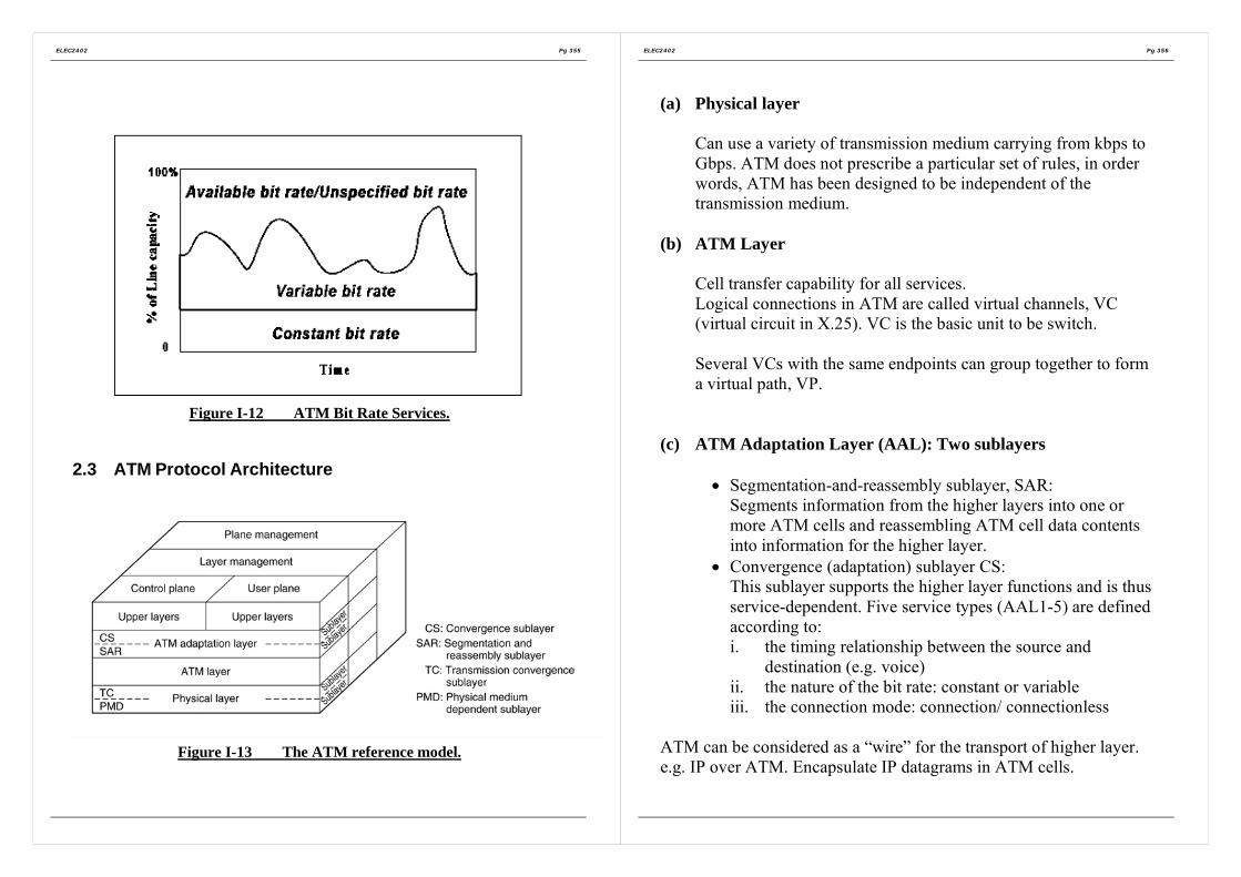
ELEC2402 Pg 355
Figure I-12 ATM Bit Rate Services.
2.3 ATM Protocol Architecture
Figure I-13 The ATM reference model.
ELEC2402 Pg 356
(a) Physical layer
Can use a variety of transmission medium carrying from kbps toGbps. ATM does not prescribe a particular set of rules, in orderwords, ATM has been designed to be independent of thetransmission medium.
(b) ATM Layer
Cell transfer capability for all services.Logical connections in ATM are called virtual channels, VC(virtual circuit in X.25). VC is the basic unit to be switch.
Several VCs with the same endpoints can group together to forma virtual path, VP.
(c) ATM Adaptation Layer (AAL): Two sublayers
• Segmentation-and-reassembly sublayer, SAR:Segments information from the higher layers into one ormore ATM cells and reassembling ATM cell data contentsinto information for the higher layer.
• Convergence (adaptation) sublayer CS:This sublayer supports the higher layer functions and is thusservice-dependent. Five service types (AAL1-5) are definedaccording to:i. the timing relationship between the source and
destination (e.g. voice)ii. the nature of the bit rate: constant or variableiii. the connection mode: connection/ connectionless
ATM can be considered as a “wire” for the transport of higher layer.e.g. IP over ATM. Encapsulate IP datagrams in ATM cells.