
Hitachi Compute Blade Emulex Adapter User's Guide for Utility

Compute Blade Built-in LAN Switch Module
Software Manual
Configuration Settings, Vol. 3Ver.10.5 and 10.7 and 11.6 compatible
BSLANSW-S009X-50
MK-99COM091-01
HITACHI

Applicable product
This manual describes model Compute Blade Built in LAN Switch Module. It also describes Built in LAN Switch Module software Ver.10.5 and 10.7 and 11.6 functions. Software functions supported by software OS-L3A and OS-L3SA is also described.
-------------------------------------------------------------------The BladeSymphony server name has been changed to Hitachi Compute
Blade. If you are using BladeSymphony based server products, substitute references to Hitachi Compute Blade with BladeSymphony.
This manual describes as substitution product code GV-BE2LSW1X1-Y for GV-BE2LSW1XR-Y and GV-BE2LSW2X1-Y for GV-BE2LSW2XR-Y.
If you use OS-L3SA, please add the prefix of ‘0/’ to the interface number of gigabitethernet to be specified by some commands.
-------------------------------------------------------------------
Caution when exporting
The necessary procedures are to be adopted when exporting this product after first confirming the regulations of the Foreign Exchange and Foreign Trade Law, U.S. export control related regulations, etc.If any questions remains, please consult with our sales department.
Trademarks
Cisco is a registered trademark of U.S. Cisco Systems, Inc. in the U.S. and other countries.Ethernet is a product name of the Xerox Corp.IPX is a trademark of Novell,Inc.Microsoft is a registered trademark of the Microsoft Corp. in the U.S. and other countries.Octpower is a trademark of NEC Corporation.UNIX is a registered trademark in the U.S. and other countries exclusively licensed by X/Open Company Limited.Windows is a registered trademark of the Microsoft Corp. in the U.S. and other countries.Other company names and product names are trademarks or registered trademarks of their respective companies.
Thoroughly read and store this manual
Read and thoroughly understand safety-related explanations before using this product.Keep this manual in a location close at hand for easy reference.
Note
The contents of this manual may be modified at any time for improvement without notice.
Issue dates
Jan. 2014 (8th edition) BSLANSW-S009X-50
Copyright
Copyright (c) Hitachi, Ltd. 2006 - 2014. All rights reserved.

Summary of amendments
8th editionIntegrated the description of all switch model.
In addition to the above changes, minor editorial corrections have been made.
7th edition
Addtion of some product code.6th edition
The BladeSymphony server name has been changed to Hitachi Compute Blade.
5th edition
No Change
4th edition
In addition to the above changes, minor editorial corrections have been made.
Item Changes
1.5 Notes on using IPv4 • This section was added.
6.5.1 List of configuration commands • This item was added.
6.5.2 Configuring the maximum number of multiplepaths handled by the Switch
• This item was added.
6.6.1 Checking the maximum number of multipaths handled by the Switch
• This item was added.
8.2.7 Applying authentication • This item was added.
14.1.6 Setting IPv4 PIM-SM BSR Candidate
• This item was added.
14.1.7 Setting IPv4 PIM-SM static rendezvous point
• This item was added.
20.1.6 Considerations when setting or changing routing protocol configurations
• This item was added.
20.5.1 List of Configuration Commands • This item was added.
20.5.2 Configuring the maximum number of multiple paths handled by the Switch
• This item was added.
20.6.1 Checking the maximum number of multiple paths handled by the Switch
• This item was added.
27.3.3 Notes on IPv6 multicast forwarding functionality
• This item was added.

[Ver. 10.7]
[Ver. 10.5.A.A]
In addition to the above changes, minor editorial corrections have been made.
[Ver. 10.5.A]
Unreleased
[Ver. 10.5]
Unreleased
Location Changes
1.3.3 ARP • "(4) Local ProxyARP" was added.
3 Null Interface (IPv4) • This chapter was added.
10.1.4 NSSA • The description of the AS excluded route advertisement was added.
17 Null Interface (IPv6) • This chapter was added.
Location Changes
8.1.3 Advertising Route Information • The description of Automatically Integrating RIP Advertising Route wasadded.
13.4.2 IPv4 PIM-SM • The explanation of Generation ID was added.
27.4.3 Neighbor Detection • The explanation of Generation ID was added.
11.1.3 Route Selection • The description of route selection by the remote BGP identifier wasmodified.
• The description of NEXT_HOP attribute resolution was modified.
11.4.1 BGP4 Peer Group BGP4 Peer Group • This subsection was added.
11.4.10 Confederation • The description of route selection by the remote BGP identifier wasmodified.
11.5.1 Configuration of BGP4 Peer Group Configuration of BGP4 Peer Group
• This subsection was added.
11.6.1 Checking BGP4 Peer Group Checking BGP4 Peer Group
• This subsection was added.
13.2 IPv4 Group Management Function • The description of IGMPv3 was added.
13.4.4 IPv4 Route Control Operation with IGMPv3 • The description of IGMPv3 was added.
14.2.4 Checking IGMP Information • The description of IGMPv3 was added.
25.1.3 Route Selection • The description of route selection by the remote BGP identifier wasmodified.
• The description of NEXT_HOP attribute resolution was modified.
25.4.1 BGP4+ Peer Group BGP4+ Peer Group • This subsection was added.
25.5.1 Configuration of BGP4+ Peer Group Configuration of BGP4+ Peer Group
• This subsection was added.
25.6.1 Checking BGP4+ Peer Group Checking BGP4+ Peer Group
• This subsection was added.

[Ver. 10.4]
Unreleased
[Ver. 10.3]
Unreleased
[Ver. 10.2]
No Change


Introduction
Introduction
Intended products and software versionsThis manual describes models Compute Blade Built-in LAN Switch Module. It also describes the functions of Compute Blade
Built-in LAN Switch Module’s software Ver. 10.5 and 10.7 and 11.6. Software functions supported by software OS-L3A and
OS-L3SA is also described.Please read the manual carefully and thoroughly understand the instructions and cautions contained herein before operating the device. Keep the manual in a location close at hand for easy reference when necessary.
A common function to all models is described in this manual as long as it doesn't refuse especially.
When use Compute Blade 2000 and 500, please read the description of Compute Blade 320 to Compute Blade 2000 or 500.
A peculiar function to Compute Blade 2000 and 500 or either Compute Blade 320 is shown respectively by the following
marks.
[CB 2000]:It is a function that supports it by the model of Compute Blade 2000 and 500.It is a function not to support in the model of Compute Blade 320 or a description that doesn't correspond.[CB 320]:It is a function that supports it by the model of Compute Blade 320.It is a function not to support in the model of Compute Blade 2000 and 500, or a description that doesn't correspond.[OS-L3A]:It is a function that supports it by OS-L3A for Compute Blade 320, 2000 and 500 LAN switch module.[OS-L3SA]:It is a function that supports it by OS-L3SA for Compute Blade 500 1Gbps(40 port) LAN switch module.
Correction of this manualContents in this manual may be corrected in the "Release note" and "Manual correction document" provided with software.
Intended usersApplicable users are system managers who develop and operate network systems using wsnal.In addition, an understanding of the following is assumed.• Basic knowledge of network system management
Sequence of manual perusalManuals to be referenced according to the flow of tasks from installation and setup to daily operations are indicated below.
I

Introduction
Conventions: abbreviations AC Alternating CurrentACK ACKnowledgeADSL Asymmetric Digital Subscriber LineALG Application Level GatewayANSI American National Standards InstituteARP Address Resolution ProtocolAS Autonomous SystemAUX AuxiliaryBGP Border Gateway Protocol
II
Introduction
BGP4 Border Gateway Protocol - version 4BGP4+ Multiprotocol Extensions for Border Gateway Protocol - version 4bit/s bits per second, usually abbreviated as bps.BPDU Bridge Protocol Data UnitBRI Basic Rate InterfaceCDP Cisco Discovery ProtocolCIDR Classless Inter-Domain RoutingCIR Committed Information RateCIST Common and Internal Spanning TreeCLNP ConnectionLess Network ProtocolCLNS ConnectionLess Network SystemCONS Connection Oriented Network SystemCRC Cyclic Redundancy CheckCSMA/CD Carrier Sense Multiple Access with Collision DetectionCSNP Complete Sequence Numbers PDUCST Common Spanning TreeDA Destination AddressDC Direct CurrentDCE Data Circuit terminating EquipmentDHCP Dynamic Host Configuration ProtocolDIS Draft International Standard/Designated Intermediate SystemDNS Domain Name SystemDR Designated RouterDSAP Destination Service Access PointDSCP Differentiated Services Code PointDTE Data Terminal EquipmentDVMRP Distance Vector Multicast Routing ProtocolE-Mail Electronic MailEAP Extensible Authentication ProtocolEAPOL EAP Over LANEFM Ethernet in the First MileES End SystemFAN Fan UnitFCS Frame Check SequenceFDB Filtering DataBaseFTTH Fiber To The HomeGBIC GigaBit Interface ConverterGSRP Gigabit Switch Redundancy ProtocolHMAC Keyed-Hashing for Message AuthenticationIANA Internet Assigned Numbers AuthorityICMP Internet Control Message ProtocolICMPv6 Internet Control Message Protocol version 6ID IdentifierIEC International Electrotechnical CommissionIEEE Institute of Electrical and Electronics Engineers, Inc.IETF the Internet Engineering Task ForceIGMP Internet Group Management ProtocolIP Internet ProtocolIPCP IP Control ProtocolIPv4 Internet Protocol version 4IPv6 Internet Protocol version 6IPV6CP IP Version 6 Control ProtocolIPX Internetwork Packet ExchangeISO International Organization for StandardizationISP Internet Service ProviderIST Internal Spanning TreeLAN Local Area NetworkLCP Link Control ProtocolLED Light Emitting DiodeLLC Logical Link ControlLLDP Link Layer Discovery ProtocolLLQ+3WFQ Low Latency Queueing + 3 Weighted Fair QueueingLSP Label Switched PathLSP Link State PDULSR Label Switched RouterMAC Media Access ControlMC Memory CardMD5 Message Digest 5MDI Medium Dependent InterfaceMDI-X Medium Dependent Interface crossoverMIB Management Information BaseMRU Maximum Receive UnitMSTI Multiple Spanning Tree InstanceMSTP Multiple Spanning Tree Protocol
III
Introduction
MTU Maximum Transfer UnitNAK Not AcKnowledgeNAS Network Access ServerNAT Network Address TranslationNCP Network Control ProtocolNDP Neighbor Discovery ProtocolNET Network Entity TitleNLA ID Next-Level Aggregation IdentifierNPDU Network Protocol Data UnitNSAP Network Service Access PointNSSA Not So Stubby AreaNTP Network Time ProtocolOADP Octpower Auto Discovery ProtocolOAM Operations,Administration,and MaintenanceOSPF Open Shortest Path FirstOUI Organizationally Unique IdentifierPAD PADdingPAE Port Access EntityPC Personal ComputerPCI Protocol Control InformationPDU Protocol Data UnitPICS Protocol Implementation Conformance StatementPID Protocol IDentifierPIM Protocol Independent MulticastPIM-DM Protocol Independent Multicast-Dense ModePIM-SM Protocol Independent Multicast-Sparse ModePIM-SSM Protocol Independent Multicast-Source Specific MulticastPoE Power over EthernetPRI Primary Rate InterfacePS Power SupplyPSNP Partial Sequence Numbers PDUQoS Quality of ServiceRA Router AdvertisementRADIUS Remote Authentication Dial In User ServiceRDI Remote Defect IndicationREJ REJectRFC Request For CommentsRIP Routing Information ProtocolRIPng Routing Information Protocol next generationRMON Remote Network Monitoring MIBRPF Reverse Path ForwardingRQ ReQuestRSTP Rapid Spanning Tree ProtocolSA Source AddressSD Secure DigitalSDH Synchronous Digital HierarchySDU Service Data UnitSEL NSAP SELectorSFD Start Frame DelimiterSFP Small Form factor PluggableSMTP Simple Mail Transfer ProtocolSNAP Sub-Network Access ProtocolSNMP Simple Network Management ProtocolSNP Sequence Numbers PDUSNPA Sub network Point of AttachmentSPF Shortest Path FirstSSAP Source Service Access PointSTP Spanning Tree ProtocolTA Terminal AdapterTACACS+ Terminal Access Controller Access Control System PlusTCP/IP Transmission Control Protocol/Internet ProtocolTLA ID Top-Level Aggregation IdentifierTLV Type, Length, and ValueTOS Type Of ServiceTPID Tag Protocol IdentifierTTL Time To LiveUDLD Uni-Directional Link DetectionUDP User Datagram ProtocolUPC Usage Parameter ControlUPC-RED Usage Parameter Control - Random Early DetectionVAA VLAN Access AgentVLAN Virtual LANVRRP Virtual Router Redundancy ProtocolWAN Wide Area Network
IV

Introduction
WDM Wavelength Division MultiplexingWFQ Weighted Fair QueueingWRED Weighted Random Early DetectionWS Work StationWWW World-Wide WebXFP 10 gigabit small Form factor Pluggable
Conventions: kB, MB, GB, and TB1kB (kilobytes), 1MB (megabytes), 1GB (gigabytes) and 1TB (terabytes) indicate 1024 bytes, 10242 bytes, 10243 bytes and
10244 bytes, respectively.
V

Introduction
VI
Contents
Part 1: IPv4 Packet Relay
1 General Description of IP/ARP/ICMP 1
1.1 Addressing 2
1.1.1 IP Address 2
1.1.2 Subnet Mask 2
1.2 IP Layer Function 3
1.2.1 Relay Function 3
1.2.2 Unit of IP Address Assignment 3
1.3 Communications Function 4
1.3.1 Internet Protocol (IP) 4
1.3.2 ICMP 5
1.3.3 ARP 6
1.4 Relay Function 9
1.4.1 IP Packet Relay Method 9
1.4.2 Broadcast Packet Relay Method 9
1.4.3 MTU and Fragment 13
1.5 Notes on using IPv4 16
2 Configuration and Operation of IP/ARP/ICMP 17
2.1 Configuration 18
2.1.1 List of Configuration Commands 18
2.1.2 Setting Interface 18
2.1.3 Setting Multihome 18
2.1.4 Setting Direct Broadcast Relay 19
2.1.5 Setting loopback Interfaces 19
2.1.6 Setting Static ARP 19
2.2 Operation 21
2.2.1 List of Operation Commands 21
2.2.2 Checking IPv4 Interface Up/Down Status 21
2.2.3 Checking Communication with Destination Address 21
2.2.4 Checking Route to Destination Address 22
2.2.5 Checking ARP Information 22
3 Null Interface (IPv4) 23
3.1 Description 24
3.2 Configuration 25
3.2.1 List of Configuration Commands 25
3.2.2 Setting the Null Interface 25
i

Contents
3.3 Operation 26
3.3.1 List of Operation Commands 26
3.3.2 Checking the Null Interface 26
4 DHCP/BOOTP Relay Agent Function 27
4.1 DHCP/BOOTP Relay Agent Function Overview 28
4.1.1 Support Specifications 28
4.1.2 Check Items When Receiving DHCP/BOOTP Packet 28
4.1.3 Setting When Relaying 28
4.1.4 Note on Using DHCP/BOOTP Relay Agent Function 29
4.2 Configuration 30
4.2.1 List of Configuration Commands 30
4.2.2 Setting for Basic Configuration 30
4.2.3 Setting for Multihome Configuration 31
4.3 Operation 33
4.3.1 List of Operation Commands 33
4.3.2 Checking DHCP/BOOTP Destination IP Address 33
5 DHCP Server Function 35
5.1 DHCP Server Function Overview 36
5.1.1 Support Specifications 36
5.1.2 Information Distributed to Clients 36
5.1.3 Dynamic DNS Cooperation 37
5.1.4 Preventing Duplicated Allocation of IP Address 37
5.1.5 Notes on Using DHCP Server Function 37
5.2 Configuration 39
5.2.1 List of Configuration Commands 39
5.2.2 Setting for Allocating IP to Client 40
5.2.3 Setting for Allocating Fixed IP to Client 41
5.2.4 Setting for Dynamic DNS Cooperation 42
5.3 Operation 44
5.3.1 List of Operation Commands 44
5.3.2 Checking Allowable Number of IP Addresses to Be Assigned 44
5.3.3 Checking Allocated IP Addresses 45
Part 2: IPv4 Routing Protocol
6 General Description of IPv4 Routing Protocol 47
6.1 IPv4 Routing Protocol Overview 48
6.1.1 Outline of Routing 48
ii
Contents
6.1.2 Static Routing and Dynamic Routing 48
6.1.3 Route Information 48
6.1.4 Application Scope by Routing Protocol 49
6.1.5 Simultaneous Operation of Routing Protocol 50
6.1.6 Notes on Concurrent Use of Multiple Protocols 51
6.1.7 Notes on Setting/Changing Configuration 54
6.2 General Operation of IPv4 Routing 55
6.2.1 List of Operation Commands 55
6.2.2 Checking Route to Destination Address 55
6.3 Network Design Concept 56
6.3.1 Address Design 56
6.3.2 Handling of Direct Route 56
6.3.3 Address Boundary Design 56
6.4 Load Balancing Overview 57
6.4.1 Outline of Load Balancing 57
6.4.2 Load Balancing Specifications 58
6.4.3 Notes on Load Balancing 59
6.5 Configuration of Load Balancing 60
6.5.1 List of configuration commands 60
6.5.2 Configuring the maximum number of multiplepaths handled by the Switch 60
6.5.3 Load Balancing Using Static Route 61
6.5.4 Load Balancing Using OSPF 61
6.5.5 Load Balancing Using BGP4 61
6.6 Operation of Load Balancing 62
6.6.1 Checking the maximum number of multipaths handled by the Switch 62
6.6.2 Checking Selected Path 62
6.7 Route Aggregation Overview 63
6.7.1 Outline of Route Aggregation 63
6.7.2 Transfer Method of Aggregated Route 63
6.7.3 Aggregation of AS_PATH Attribute 63
6.7.4 Advertisement Suppression of Aggregation Source Route 63
6.8 Configuration of Route Aggregation 65
6.8.1 List of Configuration Commands 65
6.8.2 Setting Route Aggregation and Aggregated Route Advertisement 65
6.9 Operation of Route Aggregation 66
6.9.1 List of Operation Commands 66
6.9.2 Checking Aggregated Route 66
6.10 Route Deletion Reserve Function 67
7 Static Routing (IPv4) 69
7.1 Static Routing Overview (IPv4) 70
7.1.1 Outline of Static Routing (IPv4) 70
7.1.2 Route Selection Criteria 70
iii

Contents
7.1.3 Specifying Relay Route of Static Route 71
7.1.4 Dynamic Monitoring Function 71
7.2 Configuration 74
7.2.1 List of Configuration Commands 74
7.2.2 Setting Default Route 74
7.2.3 Setting Single-path Route 74
7.2.4 Setting Multipath Route 74
7.2.5 Applying Dynamic Monitoring Function 75
7.3 Operation 76
7.3.1 List of Operation Commands 76
7.3.2 Checking Route Information 76
7.3.3 Checking Gateway Information 77
8 RIP 79
8.1 RIP Overview 80
8.1.1 Outline of RIP 80
8.1.2 Route Selection Criteria 81
8.1.3 Advertising Route Information 82
8.1.4 Learning Route Information 88
8.1.5 RIP-1 90
8.1.6 RIP-2 92
8.2 Configuration 94
8.2.1 List of Configuration Commands 94
8.2.2 Applying RIP 94
8.2.3 Setting Metric 95
8.2.4 Adjusting Timer 95
8.2.5 Suppressing RIP Packet Transmission 96
8.2.6 Limiting Destination of RIP Packet 97
8.2.7 Applying authentication 97
8.3 Operation 99
8.3.1 List of Operation Commands 99
8.3.2 Checking RIP Operation Status 99
8.3.3 Checking Destination Information 99
8.3.4 Checking Learned Route Information 100
8.3.5 Checking Advertised Route Information 100
9 OSPF 103
9.1 OSPF Basic Function Overview 104
9.1.1 Features of OSPF 104
9.1.2 Functions of OSPF 104
9.1.3 Route Selection Algorithm 105
9.1.4 Advertisement of LSA 106
iv
Contents
9.1.5 Installation Example of AS External Route 107
9.1.6 Route Selection Criteria 107
9.1.7 Equal Cost Multipath 109
9.1.8 Notes 110
9.2 Configuration of OSPF Basic Functions 111
9.2.1 List of Configuration Commands 111
9.2.2 Flow of Configuring 111
9.2.3 Setting for Applying OSPF 111
9.2.4 Setting AS External Route Advertisement 112
9.2.5 Setting Route Selection 112
9.2.6 Setting Multipath 113
9.3 Interface Overview 114
9.3.1 OSPF Interface Type 114
9.3.2 Connection with Neighboring Router 114
9.3.3 Broadcast-type Network and Designated Router 115
9.3.4 Transmission of LSA 115
9.3.5 Passive Interface 116
9.4 Configuration of Interface 117
9.4.1 List of Configuration Commands 117
9.4.2 Flow of Configuring 117
9.4.3 Setting Neighboring Router for NBMA 118
9.4.4 Setting Interface Parameter Change 118
9.5 Operation of OSPF 120
9.5.1 List of Operation Commands 120
9.5.2 Checking Domain 120
9.5.3 Checking Neighboring Router Information 121
9.5.4 Checking Interface Information 121
9.5.5 Checking LSA 122
10OSPF Extended Function 123
10.1 Area and Area Partitioning Function Overview 124
10.1.1 Area Border 124
10.1.2 Route Control with Area Partitioned 125
10.1.3 Stub Area 126
10.1.4 NSSA 126
10.1.5 Virtual Link 127
10.1.6 Virtual Link Operation 128
10.2 Configuration of Area 129
10.2.1 List of Configuration Commands 129
10.2.2 Flow of Configuring 129
10.2.3 Setting Stub Area 130
10.2.4 Setting Area Border Router 130
10.2.5 Setting Virtual Link 131
v
Contents
10.3 Neighboring Router Authentication Overview 132
10.3.1 Authentication Procedure 132
10.4 Configuration of Neighboring Router Authentication 133
10.4.1 List of Configuration Commands 133
10.4.2 Changing MD5 Authentication Key 133
10.4.3 Setting Plaintext Password 133
10.4.4 Setting MD5 Authentication 133
10.5 Graceful Restart Overview 135
10.5.1 Outline of Graceful Restart 135
10.5.2 Helper Function 135
10.5.3 Opaque LSA 135
10.6 Configuration of Graceful Restart 136
10.6.1 List of Configuration Commands 136
10.6.2 Setting Helper Function 136
10.7 Stub Router Overview 137
10.7.1 Outline of Stub Router 137
10.7.2 Stub Router Operation 137
10.8 Configuration of Stub Router 139
10.8.1 List of Configuration Commands 139
10.8.2 Stub Router Function 139
10.9 Operation of OSPF Extended Function 140
10.9.1 List of Operation Commands 140
10.9.2 Checking Area Border 140
10.9.3 Checking Area 140
10.9.4 Checking Graceful Restart 140
11BGP4 143
11.1 Basic Function Overview 144
11.1.1 Outline of BGP4 144
11.1.2 Peer Type and Connection Mode 144
11.1.3 Route Selection 146
11.1.4 Notes on Using BGP4 151
11.2 Configuration of Basic Functions 153
11.2.1 List of Configuration Commands 153
11.2.2 Flow of Configuring 154
11.2.3 Setting BGP4 Peer 155
11.2.4 Setting BGP4 Route Learning Policy 156
11.2.5 Setting BGP4 Route Advertising Policy 156
11.2.6 Setting Learned Route Filter 156
11.2.7 Setting Route Advertisement Filter 157
11.2.8 Setting Learned Route Filtering Criteria 157
11.2.9 Setting Route Advertisement Filtering Criteria 158
11.2.10 Applying Filter 158
vi

Contents
11.3 Operation of Basic Function 160
11.3.1 List of Operation Commands 160
11.3.2 Checking Peer Type and Connection Mode 160
11.3.3 Checking BGP4 Route Selection Result 161
11.3.4 Checking BGP4 Route Advertising Content 162
11.4 Extended Function Overview 163
11.4.1 BGP4 Peer Group 163
11.4.2 Community 163
11.4.3 BGP4 Multipath 165
11.4.4 Negotiation of Supported Function 166
11.4.5 Route Refresh 167
11.4.6 TCP MD5 Authentication 168
11.4.7 BGP4 Advertisement Route Generation 169
11.4.8 Route Flap Dampening 169
11.4.9 Route Reflection 170
11.4.10 Confederation 172
11.4.11 Graceful Restart 175
11.4.12 BGP4 Learned Route Restriction 178
11.5 Configuration of Extended Function 180
11.5.1 Configuration of BGP4 Peer Group 180
11.5.2 Configuring Community 181
11.5.3 Configuring BGP4 Multipath 183
11.5.4 Configuring TCP MD5 Authentication 183
11.5.5 Configuring BGP4 Advertisement Route Generation 184
11.5.6 Configuring Route Flap Dampening 185
11.5.7 Configuring Route Reflection 186
11.5.8 Configuring Confederation 187
11.5.9 Configuring Graceful Restart 188
11.5.10 Configuring BGP4 Learned Route Restriction 189
11.6 Operation of Extended Function 190
11.6.1 Checking BGP4 Peer Group 190
11.6.2 Checking Community 191
11.6.3 Checking BGP4 Multipath 192
11.6.4 Checking Supported Function Negotiation 193
11.6.5 Checking Route Refresh Function 195
11.6.6 Checking TCP MD5 Authentication 196
11.6.7 Checking BGP4 Advertisement Route Generation 197
11.6.8 Checking Route Flap Dampening 198
11.6.9 Checking Route Reflection 199
11.6.10 Checking Confederation 201
11.6.11 Checking Graceful Restart 203
11.6.12 Checking BGP4 Learned Route Restriction 204
vii

Contents
12Route Filtering (IPv4) 207
12.1 Route Filtering Overview 208
12.1.1 Outline of Route Filtering 208
12.1.2 Filtering Method 209
12.1.3 RIP 214
12.1.4 OSPF 217
12.1.5 BGP4 219
12.2 Configuration 223
12.2.1 List of Configuration Commands 223
12.2.2 RIP Learned Route Filtering 224
12.2.3 RIP Route Advertisement Filtering 226
12.2.4 OSPF Learned Route Filtering 229
12.2.5 OSPF Route Advertisement Filtering 231
12.2.6 BGP4 Learned Route Filtering 233
12.2.7 BGP4 Route Advertisement Filtering 234
12.3 Operation 238
12.3.1 List of Operation Commands 238
12.3.2 Checking Route Received by RIP (before Learned Route Filtering) 238
12.3.3 Checking Route from OSPF SPF Calculation 238
12.3.4 Checking Route Received by BGP4 (before Learned Route Filtering) 239
12.3.5 Checking Route from Learned Route Filtering 240
12.3.6 Checking Route before Route Advertisement Filtering 242
12.3.7 Checking RIP Advertised Route 243
12.3.8 Checking OSPF Advertised Route 244
12.3.9 Checking BGP4 Advertised Route 244
13General Description of IPv4 Multicast 247
13.1 IPv4 Multicast Overview 248
13.1.1 IPv4 Multicast Address 248
13.1.2 IPv4 Multicast Routing Function 249
13.2 IPv4 Group Management Function 250
13.2.1 IGMP Message Support Specifications 250
13.2.2 IGMP Operation 251
13.2.3 Querier Designation 253
13.2.4 Management of Group Members 254
13.2.5 IGMP Timer 255
13.2.6 Connection with IGMPv1/IGMPv2/IGMPv3 System 256
13.2.7 Static Group Join 257
13.2.8 Notes on Using IGMP 257
13.3 IPv4 Multicast Relay Function 258
13.4 IPv4 Route Control Function 259
viii
Contents
13.4.1 Outline of IPv4 Multicast Routing Protocol 259
13.4.2 IPv4 PIM-SM 259
13.4.3 IPv4 PIM-SSM 267
13.4.4 IPv4 Route Control Operation with IGMPv3 268
13.5 Network Design Concept 271
13.5.1 IPv4 Multicast Relay 271
13.5.2 Redundant Route (Route Switchover Due to Failure) 272
13.5.3 Adaptive Network Configuration Example 273
13.5.4 Notes on Network Configuration 274
14IPv4 Multicast Setting and Operation 279
14.1 Configuration 280
14.1.1 List of Configuration Commands 280
14.1.2 Flow of Configuring 280
14.1.3 Setting IPv4 Multicast Routing 281
14.1.4 Setting IPv4 PIM-SM 281
14.1.5 Setting IPv4 PIM-SM Rendezvous Point Related Items 282
14.1.6 Setting IPv4 PIM-SM BSR Candidate 282
14.1.7 Setting IPv4 PIM-SM static rendezvous point 283
14.1.8 Setting IPv4 PIM-SSM 283
14.1.9 Setting IGMP 284
14.2 Operation 285
14.2.1 List of Operation Commands 285
14.2.2 Checking IPv4 Multicast Group Address Route 285
14.2.3 Checking IPv4 PIM-SM Information 286
14.2.4 Checking IGMP Information 289
Part 3: IPv6 Packet Relay
15General Description of IPv6/NDP/ICMPv6 291
15.1 Addressing 292
15.1.1 IPv6 Address 292
15.1.2 Address Notation 293
15.1.3 Address Format Prefix 294
15.1.4 Unicast Address 295
15.1.5 Multicast Address 297
15.1.6 Handling of IPv6 Addresses Used in the LANSW module 299
15.1.7 Stateless Address Autoconfiguration Function 301
15.2 IPv6 Layer Function 302
15.2.1 Relay Function 302
ix

Contents
15.2.2 Unit of IPv6 Address Assignment 302
15.3 Communications Function 303
15.3.1 Internet Protocol Version 6 (IPv6) 303
15.3.2 ICMPv6 305
15.3.3 NDP 306
15.4 Relay Function 307
15.4.1 Routing Table Contents 307
15.4.2 Searching in Routing Table 307
15.5 Notes on Using IPv6 308
16Configuration and Operation of IPv6/NDP/ICMPv6 309
16.1 Configuration 310
16.1.1 List of Configuration Commands 310
16.1.2 Preparation for IPv6 Configuration 310
16.1.3 Setting Interface 310
16.1.4 Manual Setting of Link Local Address 311
16.1.5 Setting loopback Interfaces 311
16.1.6 Setting Static NDP 311
16.2 Operation 312
16.2.1 List of Operation Commands 312
16.2.2 Checking IPv6 Interface Up/Down Status 312
16.2.3 Checking Communication with Destination Address 312
16.2.4 Checking Route to Destination Address 313
16.2.5 Checking NDP Information 313
17Null Interface (IPv6) 315
17.1 Description 316
17.2 Configuration 317
17.2.1 List of Configuration Commands 317
17.2.2 Setting the Null Interface 317
17.3 Operation 318
17.3.1 List of Operation Commands 318
17.3.2 Checking the Null Interface 318
18RA 319
18.1 RA Overview 320
18.1.1 Outline of RA 320
18.1.2 Information Distribution 320
18.1.3 Handling When Prefix Information Is Changed 323
18.2 Configuration 324
18.2.1 List of Configuration Commands 324
x
Contents
18.2.2 Setting RA Transmission Suppression 324
18.2.3 Setting Information to Be Distributed 325
18.2.4 Adjusting RA Transmission Interval 325
18.3 Operation 326
18.3.1 List of Operation Commands 326
18.3.2 Checking Summary Information 326
18.3.3 Checking Detail Information 326
19IPv6 DHCP Server Function 327
19.1 IPv6 DHCP Server Function Overview 328
19.1.1 Support Specifications 328
19.1.2 Supported DHCP Options 328
19.1.3 Route Information of Distributed Prefix 329
19.1.4 Notes on Using IPv6 DHCP Server Function 330
19.2 Configuration 331
19.2.1 List of Configuration Commands 331
19.2.2 Flow of IPv6 DHCP Server Configuration 331
19.2.3 Setting Fixed Prefix for Each Client 332
19.2.4 Setting Range to Provide Dynamic Prefix 332
19.2.5 Setting Priority to Distribute Prefix to Client 333
19.2.6 Setting to Automatically Generate Route to Client to Which Prefix Is Distributed 333
19.2.7 Setting to Distribute Only Optional Information to Client 334
19.3 Operation 336
19.3.1 List of Operation Commands 336
19.3.2 Checking Allowable Number of Prefixes to Assigned 336
19.3.3 Checking Distributed Prefixes 337
Part 4: IPv6 Routing Protocol
20General Description of IPv6 Routing Protocol 339
20.1 IPv6 Routing Overview 340
20.1.1 Outline of Routing 340
20.1.2 Static Routing and Dynamic Routing 340
20.1.3 Route Information 340
20.1.4 Application Scope by Routing Protocol 341
20.1.5 Simultaneous Operation of Routing Protocol 341
20.1.6 Considerations when setting or changing routing protocol configurations 342
20.2 General Operation of IPv6 Routing 344
20.2.1 List of Operation Commands 344
20.2.2 Checking Route to Destination Address 344
xi

Contents
20.3 Network Design Concept 346
20.3.1 Address Design 346
20.3.2 Handling of Direct Route 346
20.4 Load Balancing Overview 347
20.4.1 Outline of Load Balancing 347
20.4.2 Load Balancing Specifications 347
20.4.3 Determination of Outgoing Interface 348
20.4.4 Notes on Load Balancing 348
20.5 Configuration of Load Balancing 349
20.5.1 List of Configuration Commands 349
20.5.2 Configuring the maximum number of multiple paths handled by the Switch 349
20.5.3 Load Balancing Using Static Route 350
20.5.4 Load Balancing Using OSPFv3 350
20.5.5 Load Balancing Using BGP4+ 350
20.6 Operation of Load Balancing 351
20.6.1 Checking the maximum number of multiple paths handled by the Switch 351
20.6.2 Checking Selected Path 351
20.7 Route Aggregation Overview 352
20.7.1 Outline of Route Aggregation 352
20.7.2 Transfer Method of Aggregated Route 352
20.7.3 Aggregation of AS_PATH Attribute 352
20.7.4 Advertisement Suppression of Aggregation Source Route 352
20.8 Configuration of Route Aggregation 354
20.8.1 List of Configuration Commands 354
20.8.2 Setting Route Aggregation and Aggregated Route Advertisement 354
20.9 Operation of Route Aggregation 356
20.9.1 List of Operation Commands 356
20.9.2 Checking Aggregated Route 356
20.10 Route Deletion Reserve Function 357
21Static Routing (IPv6) 359
21.1 Static Routing Overview (IPv6) 360
21.1.1 Outline of Static Routing (IPv6) 360
21.1.2 Route Selection Criteria 360
21.1.3 Specifying Relay Route of Static Route 361
21.1.4 Dynamic Monitoring Function 361
21.2 Configuration 364
21.2.1 List of Configuration Commands 364
21.2.2 Setting Default Route 364
21.2.3 Setting Single-path Route 364
21.2.4 Setting Multipath Route 364
21.2.5 Applying Dynamic Monitoring Function 365
21.3 Operation 366
xii

Contents
21.3.1 List of Operation Commands 366
21.3.2 Checking Route Information 366
21.3.3 Checking Gateway Information 367
22RIPng 369
22.1 RIPng Overview 370
22.1.1 Outline of RIPng 370
22.1.2 Route Selection Criteria 371
22.1.3 Advertising Route Information 372
22.1.4 Learning Route Information 376
22.1.5 RIPng Functions 378
22.1.6 Notes 379
22.2 Configuration 380
22.2.1 List of Configuration Commands 380
22.2.2 Applying RIPng 380
22.2.3 Setting Metric 381
22.2.4 Adjusting Timer 381
22.3 Operation 383
22.3.1 List of Operation Commands 383
22.3.2 Checking RIPng Operation Status 383
22.3.3 Checking Destination Information 383
22.3.4 Checking Learned Route Information 384
22.3.5 Checking Advertised Route Information 384
23OSPFv3 385
23.1 OSPFv3 Basic Function Overview 386
23.1.1 Features of OSPFv3 386
23.1.2 OSPFv3 Function 386
23.1.3 Route Selection Algorithm 387
23.1.4 Advertisement of LSA 388
23.1.5 Installation Example of AS External Route 389
23.1.6 Route Selection Criteria 390
23.1.7 Equal Cost Multipath 390
23.1.8 Notes 391
23.2 Configuration of OSPFv3 Basic Function 392
23.2.1 List of Configuration Commands 392
23.2.2 Flow of Configuring 392
23.2.3 Setting for Applying OSPFv3 392
23.2.4 Setting AS External Route Advertisement 393
23.2.5 Setting Route Selection 393
23.2.6 Setting Multipath 394
23.3 Interface Overview 395
xiii
Contents
23.3.1 OSPFv3 Interface Types 395
23.3.2 Connection with Neighboring Router 395
23.3.3 Broadcast-type Network and Designated Router 396
23.3.4 Transmission of LSA 396
23.3.5 Passive Interface 396
23.4 Configuration of Interface 397
23.4.1 List of Configuration Commands 397
23.4.2 Setting Interface Parameter Change 397
23.5 Operation of OSPFv3 399
23.5.1 List of Operation Commands 399
23.5.2 Checking Domain 399
23.5.3 Checking Neighboring Router Information 400
23.5.4 Checking Interface Information 400
23.5.5 Checking LSA 400
24OSPFv3 Extended Function 403
24.1 Area and Area Partitioning Function Overview 404
24.1.1 Area Border 404
24.1.2 Stub Area 405
24.1.3 Route Control with Area Partitioned 405
24.1.4 Virtual Link 406
24.1.5 Virtual Link Operation 407
24.2 Configuration of Area 408
24.2.1 List of Configuration Commands 408
24.2.2 Flow of Configuring 408
24.2.3 Setting Stub Area 409
24.2.4 Setting Area Border Router 409
24.2.5 Setting Virtual Link 410
24.3 Graceful Restart Overview 411
24.3.1 Outline of Graceful Restart 411
24.3.2 Helper Function 411
24.4 Configuration of Graceful Restart 412
24.4.1 List of Configuration Commands 412
24.4.2 Helper Function 412
24.5 Stub Router Overview 413
24.5.1 Outline of Stub Router 413
24.5.2 Stub Router Operation 413
24.6 Configuration of Stub Router 415
24.6.1 List of Configuration Commands 415
24.6.2 Stub Router Function 415
24.7 Operation of OSPFv3 Extended Function 416
24.7.1 List of Operation Commands 416
24.7.2 Checking Area Border 416
xiv
Contents
24.7.3 Checking Area 416
24.7.4 Checking Graceful Restart 416
25BGP4+ 419
25.1 Basic Function Overview 420
25.1.1 Outline of BGP4+ 420
25.1.2 Peer Type and Connection Mode 420
25.1.3 Route Selection 422
25.1.4 Notes on Using BGP4+ 427
25.2 Configuration of Basic Functions 430
25.2.1 List of Configuration Commands 430
25.2.2 Flow of Configuring 431
25.2.3 Setting BGP4+ Peer 432
25.2.4 Setting BGP4+ Route Learning Policy 433
25.2.5 Setting BGP4+ Route Advertising Policy 433
25.2.6 Setting Learned Route Filter 434
25.2.7 Setting Route Advertisement Filter 434
25.2.8 Setting Learned Route Filtering Criteria 435
25.2.9 Setting Route Advertisement Filtering Criteria 435
25.2.10 Applying Filter 436
25.3 Operation of Basic Function 437
25.3.1 List of Operation Commands 437
25.3.2 Checking Peer Type and Connection Mode 437
25.3.3 Checking BGP4+ Route Selection Result 438
25.3.4 Checking BGP4+ Route Advertising Content 439
25.4 Extended Function Overview 441
25.4.1 BGP4+ Peer Group 441
25.4.2 Community 441
25.4.3 BGP4+ Multipath 441
25.4.4 Negotiation of Supported Function 441
25.4.5 Route Refresh 442
25.4.6 TCP MD5 Authentication 443
25.4.7 BGP4+ Advertisement Route Generation 443
25.4.8 Route Flap Dampening 443
25.4.9 Route Reflection 443
25.4.10 Confederation 444
25.4.11 Graceful Restart 444
25.4.12 BGP4+ Learned Route Restriction 444
25.5 Configuration of Extended Function 445
25.5.1 Configuration of BGP4+ Peer Group 445
25.5.2 Configuring Community 446
25.5.3 Configuring BGP4+ Multipath 448
25.5.4 Configuring TCP MD5 Authentication 449
xv

Contents
25.5.5 Configuring BGP4+ Advertisement Route Generation 449
25.5.6 Configuring Route Flap Dampening 451
25.5.7 Configuring Route Reflection 451
25.5.8 Configuring Confederation 453
25.5.9 Configuring Graceful Restart 454
25.5.10 Configuring BGP4+ Learned Route Restriction 455
25.6 Operation of Extended Function 457
25.6.1 Checking BGP4+ Peer Group 457
25.6.2 Checking Community 458
25.6.3 Checking BGP4+ Multipath 460
25.6.4 Checking Supported Function Negotiation 460
25.6.5 Checking Route Refresh Function 462
25.6.6 Checking TCP MD5 Authentication 463
25.6.7 Checking BGP4+ Advertisement Route Generation 464
25.6.8 Checking Route Flap Dampening 465
25.6.9 Checking Route Reflection 466
25.6.10 Checking Confederation 468
25.6.11 Checking Graceful Restart 470
25.6.12 Checking BGP4+ Learned Route Restriction 471
26Route Filtering (IPv6) 473
26.1 Route Filtering Overview 474
26.1.1 Outline of Route Filtering 474
26.1.2 Filtering Method 475
26.1.3 RIPng 480
26.1.4 OSPFv3 482
26.1.5 BGP4+ 485
26.2 Configuration 489
26.2.1 List of Configuration Commands 489
26.2.2 RIPng Learned Route Filtering 490
26.2.3 RIPng Route Advertisement Filtering 492
26.2.4 OSPFv3 Learned Route Filtering 495
26.2.5 OSPFv3 Route Advertisement Filtering 496
26.2.6 BGP4+ Learned Route Filtering 499
26.2.7 BGP4+ Route Advertisement Filtering 500
26.3 Operation 503
26.3.1 Checking Route Received by RIPng (before Learned Route Filtering) 503
26.3.2 Checking Route from OSPFv3 SPF Calculation 503
26.3.3 Checking Route Received by BGP4+ (before Learned Route Filtering) 504
26.3.4 Checking Route from Learned Route Filtering 505
26.3.5 Checking Route before Route Advertisement Filtering 508
26.3.6 Checking RIPng Advertised Route 510
26.3.7 Checking OSPFv3 Advertised Route 510
xvi
Contents
26.3.8 Checking BGP4+ Advertised Route 510
27General Description of IPv6 Multicast 513
27.1 IPv6 Multicast Overview 514
27.1.1 IPv6 Multicast Address 514
27.1.2 IPv6 Multicast Routing Function 514
27.2 IPv6 Group Management Function 515
27.2.1 Outline of MLD 515
27.2.2 Operation of MLD 515
27.2.3 Querier Designation 518
27.2.4 Management of IPv6 Group Members 519
27.2.5 MLD Timer Value 520
27.2.6 Connection to MLDv1/MLDv2 System 521
27.2.7 Static Group Join 522
27.2.8 Notes on Using MLD 522
27.3 IPv6 Multicast Relay Function 523
27.3.1 Address to Be Forwarded 523
27.3.2 Forwarding of IPv6 Multicast Packet 523
27.3.3 Notes on IPv6 multicast forwarding functionality 524
27.4 IPv6 Route Control Function 525
27.4.1 Outline of IPv6 Multicast Routing Protocol 525
27.4.2 IPv6 PIM-SM 525
27.4.3 Neighbor Detection 529
27.4.4 Determination of Forwarder 530
27.4.5 DR Determination and Operation 531
27.4.6 IPv6 PIM-SM Operation with MLDv2 532
27.4.7 Notes on Using a Redundant Route 532
27.4.8 IPv6 PIM-SM Timer Specifications 533
27.4.9 Notes on Using IPv6 PIM-SM 534
27.4.10 IPv6 PIM-SSM 535
27.5 Network Design Concept 539
27.5.1 IPv6 Multicast Relay 539
27.5.2 Redundant Route (Route Switchover Due to Failure) 540
27.5.3 Adaptive Network Configuration Example 541
27.5.4 Notes on Network Configuration 542
28Configuration and Operation of IPv6 Multicast 549
28.1 Configuration 550
28.1.1 List of Configuration Commands 550
28.1.2 Flow of Configuring 550
28.1.3 Setting IPv6 Multicast Routing 551
28.1.4 Setting IPv6 PIM-SM 551
xvii

Contents
28.1.5 Setting IPv6 PIM-SM Rendezvous Point Related Items 552
28.1.6 Setting IPv6 PIM-SSM 552
28.1.7 Setting MLD 554
28.2 Operation 555
28.2.1 List of Operation Commands 555
28.2.2 Checking IPv6 Multicast Group Address Route 555
28.2.3 Checking IPv6 PIM-SM Information 556
28.2.4 Checking MLD Information 559
Appendix 561
Appendix A Conformed Standards 562
Appendix A.1 IP/ARP/ICMP 562
Appendix A.2 DHCP/BOOTP Relay Agent 562
Appendix A.3 DHCP Server Function 562
Appendix A.4 RIP 562
Appendix A.5 OSPF 563
Appendix A.6 BGP4 563
Appendix A.7 IPv4 Multicast 563
Appendix A.8 IPv6/NDP/ICMPv6 564
Appendix A.9 IPv6 DHCP Server 564
Appendix A.10 RIPng 564
Appendix A.11 OSPFv3 564
Appendix A.12 BGP4+ 565
Appendix A.13 IPv6 Multicast 565
Index 567
xviii

1. General Description of IP/ARP/ICMP
Part 1 IPv4 Packet Relay
1 General Description of IP/ARP/ICMPAn IPv4 network has a communication function, an IP packet relay function, and a route control function. This chapter describes the addressing and IPv4 packet relay.
1.1 Addressing
1.2 IP Layer Function
1.3 Communications Function
1.4 Relay Function
1.5 Notes on using IPv4
1

1. General Description of IP/ARP/ICMP
1.1 Addressing
This section describes addressing of IP address.
1.1.1 IP AddressThe LANSW module supports IP address class A, class B, class C, and class D. Class D is used in routing protocol. CIDR (Classless Inter-Domain Routing) addressing is also supported, although this depends on the routing protocol being used. The following figure shows the IP address format.
Figure 1-1: IP Address Format
Two types of network broadcast addresses and subnetwork broadcast addresses are supported: ones with all 1s or all 0s as the host ID. See "1.2.2 Unit of IP Address Assignment" for information regarding interfaces.
The following IP address ranges can be used for the LANSW module.
net IDNet ID in the range described below can be used as net ID.• Class A: 1.x.x.x to 126.x.x.x• Class B: 128.1.x.x to 191.254.x.x• Class C: 192.0.1.x to 223.255.254.x (x=host ID)
host IDHost ID in the range described below can be used as host ID.• Class A: y.0.0.1 to y.255.255.254• Class B: y.y.0.1 to y.y.255.254• Class C: y.y.y.1 to y.y.y.254 (y=net ID)
1.1.2 Subnet MaskThe boundary position of net and host IDs can be specified at an arbitrary boundary position using a subnet mask, irrespective of the boundary position of net and host IDs of Classes A, B, and C, as shown in "Figure 1-1: IP Address Format".
For example, set the subnet mask 255.255.255.0 when obtaining one net ID of Class B and using it by dividing the net ID into 256 subnets. Also as a usage corresponding to CIDR, set the subnet mask 255.255.254.0 when obtaining two continuous net IDs (e.g. 192.0.0.x and 192.0.1.x) of Class C and using it as one subnetwork.
Subnet mask is specified left-justified (series of "1" starting from the higher bit of binary representation) for each interface using configuration.
For example, 255.255.192.0 can be set to the subnet mask, but 255.255.96.0 cannot be set.
2

1. General Description of IP/ARP/ICMP
1.2 IP Layer Function
1.2.1 Relay FunctionThe LANSW module relays received IP packets according to the routing table. This relaying process can be divided into the following three major functions:
• Communications functionProcesses sending and receiving of IP layers.
• Relay functionRelays IP packets according to the routing table.
• Route control functionSends/receives routing information, determines the relay route, creates the routing table.
The figure below shows outline of the IPv4 Routing Function.
Figure 1-2: Outline of IPv4 Routing Function
1.2.2 Unit of IP Address AssignmentThe LANSW module sets IP address for VLAN. Multihome connection that enable setting of multiple IP addresses for a single VLAN is also supported. The form of connection to the network is broadcast type.
3

1. General Description of IP/ARP/ICMP
1.3 Communications Function
This section provides an explanation of the communication protocols used in IPv4 packet relays. The following protocols can be used for IPv4 communications.
• IP• ICMP• ARP
1.3.1 Internet Protocol (IP)
(1) IP packet format
Format and default values for IP packets sent by the LANSW module are based on RFC791.
(2) IP packet header validity check
IP packet headers are checked for validity on reception of IP packets. The content of check performed on IP packet header items is shown in the table below.
Table 1-1: Check Items of IP Packet Header
(Legend) Y: Performed N: Not performed -: Not applicable* Sends an ICMP Time Exceeded message.
(3) IP option support specifications
The IP option supported by the LANSW module are shown in the table below.
IP Packet Header Field Check Item When Check Is Invalid Packet Is
Discarded
When Packet Is Discarded ICMP
Is Sent
Version If version = 4 Y N
Header length Header length ≥ 5 Y N
TOS Not checked - -
Total length Total length ≥ 4 × header length Y N
Packet identifier Not checked - -
Flag Not checked - -
Fragment offset Not checked - -
TTL TTL for received packets sent to own system:Not checked
- -
Forwarded packet TTL:TTL-1 > 0
Y Y*
Protocol Not checked - -
Header checksum Header checksum is correct Y N
Source address Not checked - -
Destination address All of the following conditions are met:1. Class A, Class B, Class C, Class D2. Network number is other than 127 (internal
loopback address)3. Network number is other than 0 (except
0.0.0.0)
Y N
4

1. General Description of IP/ARP/ICMP
Table 1-2: IP Option Support Specifications
(Legend) Y: Supported N: Not supported -: No options
1.3.2 ICMP
(1) ICMP message format
The format and default values of ICMP message that the LANSW module sends are based on RFC792.
(2) ICMP message support specifications
The ICMP message support specifications are shown in the table below.
Table 1-3: ICMP Message Support Specifications (Decimal Values)
IP Option IP Packet Category
Packets Originating from the LANSW module
Packets Terminating at the LANSW module
Packets Relayed by the LANSW module
End of Option List Y - -
No Operation Y - -
Loose Source Routing Y Y Y
Strict Source Routing N Y Y
Record Route Y Y Y
Internet Timestamp N Y Y
ICMP Message Support
Type Code (Detail Type)
- Value - Value
Destination Unreachable 3 Net Unreachable 0 Y
Host Unreachable 1 Y
Protocol Unreachable 2 Y
Port Unreachable 3 Y
Fragmentation Needed and DF Set 4 Y
Source Route Failed 5 Y
Destination Network Unknown 6 N
Destination Host Unknown 7 N
Network Unreachable for Type of Service 11 N
Host Unreachable for Type of Service 12 N
Communication Administratively Prohibited 13 Y
Host Precedence Violation 14 N
Precedence Cutoff in Effect 15 N
Source Quench 4 - 0 N
5

1. General Description of IP/ARP/ICMP
(Legend) Y: Supported N: Not supported -: Not applicable* "Reply message" is returned when "Request message" is received.
(3) ICMP Redirect transmission specifications
Packets of ICMP Redirect are sent when the following conditions are met:
• Packet sender and next hop router are in the same segment (subnetwork address of source IP address and that of the relay destination next hop address for an incoming packet are the same).
• Incoming packets are IP packets other than ICMP.• The transmission validity is specified using IP routing information of configuration.
(4) ICMP Time Exceeded transmission specifications
ICMP Time Exceeded packets are sent when the following conditions are met:
• TTL of incoming packets being forwarded is 1.• Incoming packets are IP packets other than ICMP (with exception of ICMP Echo packets).
1.3.3 ARP
(1) ARP frame format
The format and default values of ARP frames sent by the LANSW module are based on RFC826.
(2) ARP frame validity check
The LANSW module checks for validity of received ARP frames. The following table shows the contents of ARP
Redirect 5 Redirect Datagrams for the Network 0 N
Redirect Datagrams for the Host 1 Y
Redirect Datagrams for the Type of Service and Network
2 N
Redirect Datagrams for the Type of Service and Host
3 N
Time Exceeded 11 Time to Live Exceeded in Transit 0 Y
Fragment Reassembly Time Exceeded 1 N
Parameter Problem 12 - 0 Y
Echo Request 8 - 0 Y
Echo Reply 0 - 0 Y
Timestamp Request 13 - 0 N
Timestamp Reply 14 - 0 Y*
Information Request 15 - 0 N
Information Reply 16 - 0 N
Address Mask Request 17 - 0 N
Address Mask Reply 18 - 0 Y*
ICMP Message Support
Type Code (Detail Type)
- Value - Value
6

1. General Description of IP/ARP/ICMP
frame check.
Table 1-4: Check Items of ARP Frame
(Legend) Y: Discard when check is not valid -: Not applicable
* Sending of "Trailer packet" is not performed, but response is returned to learn if requested.
(3) ProxyARP
The LANSW module enables operation of ProxyARP for any interfaces. The configuration determines whether or not action is taken. The LANSW module sends ARP reply packets as proxy for the destination protocol address when ARP request packet meeting all the following conditions is received.
• The destination protocol address of the ARP request packets is NOT a broadcast address.• The network number of the source protocol address and destination protocol address of the ARP request packets are
the same.• The subnetwork number of the source protocol address and destination protocol address of the ARP request packets
are different.• The destination protocol address of the ARP request packets is in the routing table and reachable.
(4) Local ProxyARP
This device can operate local ProxyARP for all interfaces. The configuration can be used to specify whether or not operation is available.
The following indicates differences between ProxyARP and local ProxyARP:
• ProxyARP is the terminal not mainly supporting the routing. So, it makes a response by proxy for the ARP request issued to the subnet of the interface different from the ARP reception interface.
• Local ProxyARP makes a response by proxy for ARP request issued to the subnet of the reception interface.
This function is used with the subnet in which terminals cannot directly communicate with each other for a security reason or with the subnet for which broadcasting is prohibited. Moreover, If this function is used, communication
ARP Frame Field Check Item Frames Discarded
Hardware type (For Ethernet)Hardware type=1 (Ethernet)
Y
Protocol type Protocol = 0800H (IP)1000H (Trailer packet)*
Y
Hardware address length Not checked -
Protocol address length Not checked -
Operation code Operation code = 1 (REQUEST), treated as 2 (REPLY) if not 1 -
Source hardware address Not any of the following• Multicast Address• Broadcast address• Same as local system hardware address
Y
Source protocol address Not any of the following• Multicast Address• Same as local system protocol address• 0.0.0.0
Y
Destination hardware address • Hardware address of local system• Broadcast address
Y
Destination protocol address • Must be local system protocol address Y
7

1. General Description of IP/ARP/ICMP
among terminals on the same subnet is relayed through this device. This function generates many ICMP redirects. So, it is recommended to disable the ICMP redirect function.
When this device receives the ARP request packet that satisfies all of the following conditions, it transmits the ARP response packet as the proxy of the destination protocol address.
The following indicates differences between ProxyARP and local ProxyARP:
• The destination protocol address of the ARP request packet is not the broadcast address.• The subnet work number of the destination protocol address of the ARP request packet is equal to the subnet number
of the reception interface.• The transmission source protocol address is not the same as the destination protocol address.
(5) Aging timer
The aging time of ARP information can be set in each interface. You can specify a value between 1 minute and 24 hours. Default is 4 hours.
(6) Setting of ARP information
To connect products that do not have ARP protocol, you can configure the corresponding MAC address and IP address (ARP information) by configuration command arp.
(7) Referencing of ARP information
You can reference ARP information using show ip arp command from the operation terminals. The relationship between the IP address and MAC address of an interface can be recognized from the ARP information.
8
1. General Description of IP/ARP/ICMP
1.4 Relay Function
1.4.1 IP Packet Relay MethodThe relay function relays received packets to the next router or host according to the routing table.
(1) Routing table contents
A routing table consists of multiple entries and each entry contains the following information. The content of routing table included in the LANSW module can be displayed with the show ip route command.
Destination:Destination address and bit length of subnet mask for destination network address. The subnet mask becomes a mask for the destination IP addresses of incoming IP packets when the routing table is searched. For the destination network addresses that are not divided into subnetworks, a mask bit length that corresponds to the network class for the network address (e.g., 8 for classA) is displayed. When the host address is used for relaying, 32 is displayed.
Next Hop: IP address for next router. Multiple Next Hops exist when using multipath function.
Interface: Interface name of Next Hop.
Metric: Route metric.
Protocol: Learning source protocol.
Age: Time (in second(s)) after route was verified or changed.
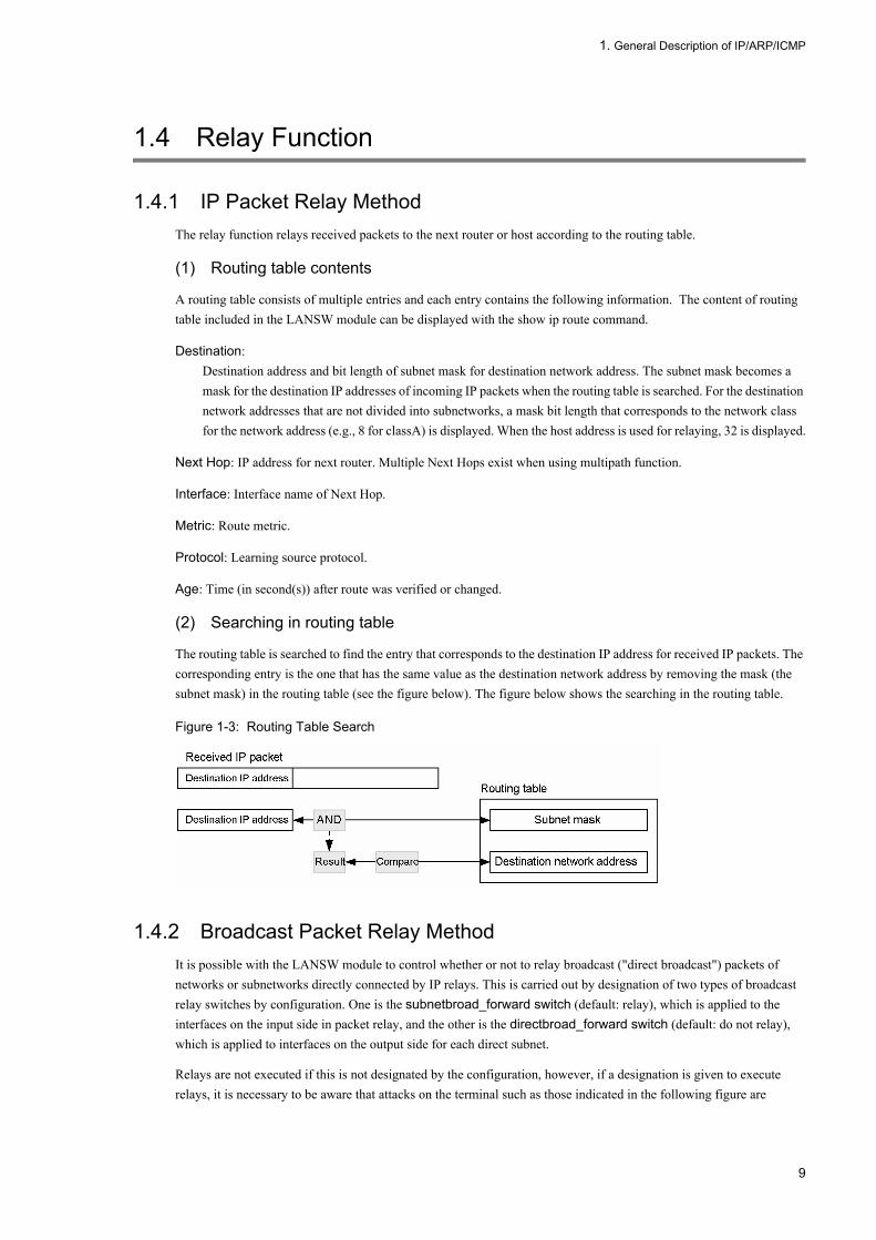
(2) Searching in routing table
The routing table is searched to find the entry that corresponds to the destination IP address for received IP packets. The corresponding entry is the one that has the same value as the destination network address by removing the mask (the subnet mask) in the routing table (see the figure below). The figure below shows the searching in the routing table.
Figure 1-3: Routing Table Search
1.4.2 Broadcast Packet Relay MethodIt is possible with the LANSW module to control whether or not to relay broadcast ("direct broadcast") packets of networks or subnetworks directly connected by IP relays. This is carried out by designation of two types of broadcast relay switches by configuration. One is the subnetbroad_forward switch (default: relay), which is applied to the interfaces on the input side in packet relay, and the other is the directbroad_forward switch (default: do not relay), which is applied to interfaces on the output side for each direct subnet.
Relays are not executed if this is not designated by the configuration, however, if a designation is given to execute relays, it is necessary to be aware that attacks on the terminal such as those indicated in the following figure are
9

1. General Description of IP/ARP/ICMP
possible.
Figure 1-4: Example of an Attack on Subnetworks Using a Broadcast Packet
Direct broadcast packets are relayed if you set the "ip subnet-broadcast" command, as well as the "directed-broadcast" parameter of the "ip address" command. The relationship between the setup and operation between these commands (parameters) is explained in the following table. Examples of setting these commands are also shown in the following figure.
Table 1-5: Command setting and operation
(Legend) Y: Relayed N: Not relayed
ip subnet-broadcast command ip address command
"Ip subnet-broadcast" Specification
"Ip subnet-broadcast" is not specified
When default and "Ip subnet-broadcast" is set Y N
When "no Ip subnet-broadcast" is set N N
10

1. General Description of IP/ARP/ICMP
Figure 1-5: Setting Example of Using Both Switches
(1) Network broadcast
Network broadcast is the broadcast type for networks that have not been converted to subnetworks. For example, if a network broadcast IP packet with destination 100.1.255.255 is sent to 100.1.0.0/16 class B network, the LANSW module directly connecting to the 100.1.0.0/16 network judges whether to forward the packet to subordinate networks by the broadcast forwarding switch setting of the configuration. The following figure shows the network broadcast.
Figure 1-6: Network Broadcast
(2) Subnetwork broadcast
Subnetwork broadcast is the broadcast type for networks that have been divided into subnetworks.
For example, if a subnetwork broadcast IP packet with the destination 100.1.1.255 (i.e. broadcast to 100.1.1.0/24) is sent when 100.1.0.0/16 class B network is divided into two subnetworks (100.1.1.0/24 and 100.1.2.0/24), the LANSW module directly connecting to the 100.1.1.0/24 subnetwork judges whether to forward the packet to subordinate subnetworks, according to the broadcast forwarding switch setting of the configuration. The following figure shows the subnetwork broadcast.
11

1. General Description of IP/ARP/ICMP
Figure 1-7: Subnetwork Broadcast
(3) All-subnetwork broadcast
All-subnetwork broadcast is the broadcast type for all networks that have been converted to subnetworks.
For example, if all-subnetwork broadcast IP packets with 100.1.255.255 as the destination are sent when the 100.1.0.0/16 class B network is used as a subnetwork and divided into two subnetworks (100.1.1.0/24 and 100.1.2.0/24), the corresponding packets are sent to the LANSW module that directly stores the 100.1.1.0/24 and 100.1.2.0/24 subnetworks. They are not forwarded to subordinate subnetworks 100.1.1.0/24 and 100.1.2.0/24, but are discarded by the LANSW module instead. The figure below shows the all-subnetwork broadcast.
Figure 1-8: All-subnetwork Broadcast
12

1. General Description of IP/ARP/ICMP
1.4.3 MTU and FragmentAn IP packet is relayed according to the maximum transfer unit (MTU). Packets greater than that value are divided and transmitted. This is called fragmentation. Packets that can be accommodated in the size of the MTU are relayed by hardware, but transmission upon dividing uses software relay. Be careful that the relay performance may be reduced in the software relay.
(1) Determination of MTU
Determination of MTU of Ethernet interfaceWhen MTU value is set for Ethernet interface by configuration command mtu, the value set for the port MTU is used as the MTU value of the relevant line, regardless of system MTU information set by configuration command system mtu and IP MTU information set by configuration command ip mtu.This MTU value is used when MTU of the VLAN interface shown below is not used.
Determination of MTU of VLAN interfaceAmong MTU value of Ethernet interface belonging to VLAN, system MTU information, and IP MTU information, the smallest one is used as the MTU value of the VLAN interface.MTU value of the VLAN interface is mainly used in the following case.• IPv4 packet relay with option• Packets originating from the LANSW module
The table below shows the MTU determination matrix of the VLAN interfaces:
Table 1-6: VLAN Interface MTU Value Setting Matrix
(Legend)A1: Value set in system MTU information or IP MTU information, whichever is smallerA2: Value set in IP MTU information or smallest value in port specified in port MTU information, whichever is smallerA3: IP MTU information or 1500, whichever is smallerA4: Smallest value in port specified in port MTU informationA5: 1500
Note: When the line type is 10BASE-T (full/half-duplex) or 100BASE-TX (half-duplex), MTU value is 1500 regardless of settings.
Setting Pattern 1 2 3 4 5 6 7 8
System MTU information With setting
With setting
With setting
With setting
Default Default Default Default
IP MTU information With setting
With setting
Default Default With setting
With setting
Default Default
Port MTU information With setting
Default With setting
Default With setting
Default With setting
Default
MTU value A2 A1 A4 A1 A2 A3 A4 A5
13

1. General Description of IP/ARP/ICMP
Figure 1-9: Setting Example of VLAN Interface
• When IP is not set
[MTU value determined]MTU value of VLAN100: 1600MTU value of VLAN200: 1900
• When IP is setWhen ip mtu 1000 is set for VLAN100 and ip mtu 3000 is set for VLAN 200
[MTU value determined]MTU value of VLAN100: 1000MTU value of VLAN200: 1900
(2) MTU and fragment
There is a possibility that subnetworks with different MTUs exist in the network. When an IP packet of large size passes a network having a small MTU, the IP packet is divided and relayed.
Fragmentation model is shown in the following figure. As shown in the figure below, when relaying the packet transmitted from Network A into Network B, the packet is fragmented because the MTU is decreased from 1500 to 630.
Figure 1-10: Fragmentation Model
(3) Creating fragments
An IP packet exceeding the MTU has the data portion, except the IP header, fragmented by lengths of multiples of eight.
Since net B has an MTU at 630, it becomes 610 when the IP header length is excluded, and since the length of multiples of eight at 610 is 608, it is fragmented by 608 bytes. The fragmented packets are added with their respective IP headers. Packet fragmentation is shown in the following figure.
14
1. General Description of IP/ARP/ICMP
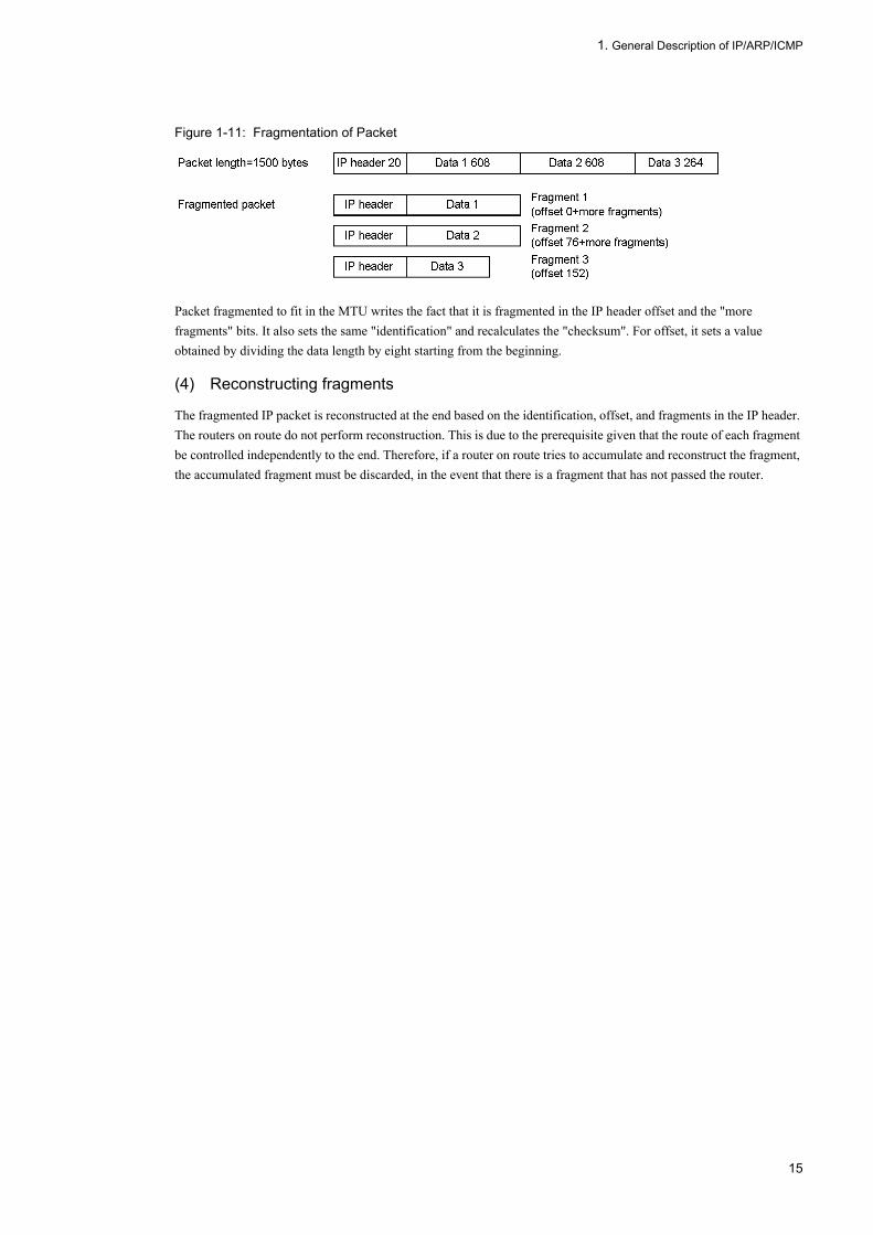
Figure 1-11: Fragmentation of Packet
Packet fragmented to fit in the MTU writes the fact that it is fragmented in the IP header offset and the "more fragments" bits. It also sets the same "identification" and recalculates the "checksum". For offset, it sets a value obtained by dividing the data length by eight starting from the beginning.
(4) Reconstructing fragments
The fragmented IP packet is reconstructed at the end based on the identification, offset, and fragments in the IP header. The routers on route do not perform reconstruction. This is due to the prerequisite given that the route of each fragment be controlled independently to the end. Therefore, if a router on route tries to accumulate and reconstruct the fragment, the accumulated fragment must be discarded, in the event that there is a fragment that has not passed the router.
15

1. General Description of IP/ARP/ICMP
1.5 Notes on using IPv4
(1) Notes on multi-homed configurations
When you assign multiple IPv4 addresses to an interface, if terminals that belong to the same broadcast domain as the interface use different subnet addresses to communicate with one another, IPv4 forwarding can occur via the Switch.
If forwarding does occur, the hardware forwards the packets to the software so that the software can determine whether an ICMP Redirect message can be sent. Because this process significantly increases the load on the CPU of the Switch, note the following ways to prevent this problem:
• When terminals in the same broadcast domain are allowed to directly communicate with each other, use the same subnet for all terminals.
• If you need to assign different subnets to the terminals in the same broadcast domain for security reasons, we recommend that you avoid high CPU load by using the appropriate configuration command to stop the hardware from making a determination regarding whether ICMP Redirect messages can be sent.
16

2. Configuration and Operation of IP/ARP/ICMP
2 Configuration and Operation of IP/ARP/ICMPThis chapter explains how to configure of IPv4 network and how to check its status.
2.1 Configuration
2.2 Operation
17

2. Configuration and Operation of IP/ARP/ICMP
2.1 Configuration
2.1.1 List of Configuration CommandsThe IPv4 configuration command list is shown in the table below.
Table 2-1: List of Configuration Commands
2.1.2 Setting Interface[Point of setting]
Set IPv4 address for VLAN. To set IPv4 address, you must move to interface configuration mode.
[Setup using commands]
1. (config)# interface vlan 100
Moves to interface configuration mode of VLAN ID 100.
2. (config-if)# ip address 192.168.1.1 255.255.255.0
Sets IPv4 address 192.168.1.1 and subnet mask 255.255.255.0 for VLAN ID 100.
2.1.3 Setting Multihome[Point of setting]
Set multiple IPv4 addresses for VLAN. The secondary parameter must be specified for the second and subsequent IPv4 addresses.
[Setup using commands]
Command Description
arp Creates a static ARP table.
arp discard-unresolved-packets Reduces the CPU load by using the hardware to discard IPv4 forwarding packets with unresolved addresses.
arp max-send-count Specifies the maximum number of transmission retries for an ARP request frame.
arp send-interval Specifies the transmission retry interval for an ARP request frame.
arp timeout Specifies ARP cache aging time.
ip address Specifies IPv4 address of the interface.
ip icmp rate-limit unreachable Specifies a transmission interval for ICMP error.
ip local-proxy-arp Specifies whether a local Proxy ARP reply can be returned.
ip mtu Specifies IP MTU length for the interface.
ip proxy-arp Specifies whether to disable or enable ARP proxy reply.
ip redirects Specifies whether ICMP redirect messages are transmitted or not.
ip routing no ip routing invalidates IPv4 and IPv6 forwarding.
ip source-route Specifies whether to disable or enable forwarding of IPv4 packets with the source route option.
ip subnet-broadcast Specifies whether to disable or enable the forwarding of subnet broadcast IPv4 packet. When setting forwarding of the broadcast packet, directed-broadcast parameter of ip address command must also be set.
18
2. Configuration and Operation of IP/ARP/ICMP
1. (config)# interface vlan 100
Moves to interface configuration mode of VLAN ID 100.
2. (config-if)# ip address 192.168.1.1 255.255.255.0
Sets primary IPv4 address 192.168.1.1 and subnet mask 255.255.255.0 for VLAN ID 100.
3. (config-if)# ip address 170.1.1.1 255.255.255.0 secondary
Sets secondary IPv4 address 170.1.1.1 and subnet mask 255.255.255.0 for VLAN ID 100.
2.1.4 Setting Direct Broadcast Relay[Point of setting]
To enable direct broadcast relay, directed-broadcast parameter of ip address command must be enabled. When subnet broadcast packet relay is suppressed by no ip subnet-broadcast command, execute ip subnet-broadcast command to enable subnet broadcast packet relay.
[Setup using commands]
1. (config)# interface vlan 100
Moves to interface configuration mode of VLAN ID 100.
2. (config-if)# ip subnet-broadcast
Enables the subnet broadcast packet replay option (this setting is only required when no ip subnet-broadcast was executed before).
3. (config-if)# ip address 170.10.10.1 255.255.255.0 directed-broadcast
Sets the primary IP address 170.10.10.1, subnet mask 255.255.255.0, and direct broadcast IPv4 packet relay for VLAN ID 100.
2.1.5 Setting loopback Interfaces[Point of setting]
Set an IPv4 address to identify the LANSW module. Only 0 can be specified for the interface number, and only one address can be set.
[Setup using commands]
1. (config)# interface loopback 0
Moves to interface configuration mode of the loopback interface.
2. (config-if)# ip address 192.168.1.1
Sets IP address 192.168.1.1 for the loopback interface.
2.1.6 Setting Static ARP[Point of setting]
Set static ARP at the LANSW module.Interface must be specified.
19

2. Configuration and Operation of IP/ARP/ICMP
[Setup using commands]
1. (config)# arp 123.10.1.1 interface vlan 100 0012.e240.0a00
Sets the static ARP for VLAN ID 100, with next hop IPv4 address 123.10.1.1 and destination MAC address 0012.e240.0a00.
20

2. Configuration and Operation of IP/ARP/ICMP
2.2 Operation
2.2.1 List of Operation CommandsTable below shows the operation command list of IP, ARP, and ICMP.
Table 2-2: List of Operation Commands
2.2.2 Checking IPv4 Interface Up/Down StatusAfter an IPv4 address is set for the line of the LANSW module connected to the IPv4 network or the port in the line, execute the show ip interface command and make sure that the up/down status of the IPv4 interface is "UP".
Figure 2-1: Display Example of IPv4 Interface Status
> show ip interface summaryvlan100 : UP 158.215.100.1/24vlan200 : UP 123.10.1.1/24 >
2.2.3 Checking Communication with Destination AddressFor the interface of the LANSW module connected to the IPv4 network, check to see if communication with the remote system is enabled using the command "ping".
Figure 2-2: Execution Result of ping Command (for Communication Enabled)
> ping 192.168.0.1PING 192.168.0.1 (192.168.0.1): 56 data bytes64 bytes from 192.168.1.51: icmp_seq=0 ttl=255 time=0.286 ms64 bytes from 192.168.1.51: icmp_seq=1 ttl=255 time=0.271 ms64 bytes from 192.168.1.51: icmp_seq=2 ttl=255 time=0.266 ms^C--- 192.168.0.1 PING Statistics ---3 packets transmitted, 3 packets received, 0.0% packet lossround-trip min/avg/max = 0.266/0.274/0.286 ms>
Command Description
show ip-dual interface Displays the IPv4 and IPv6 interface state.
show ip interface Displays the IPv4 interface state.
show ip arp Displays ARP entry information.
clear arp-cache Deletes dynamic ARP information.
show netstat (netstat) Displays the network status.
clear netstat Clears the network statistics information counter.
clear tcp Disconnects TCP connection.
ping Performs echo test.
traceroute Displays the traced route.
21

2. Configuration and Operation of IP/ARP/ICMP
Figure 2-3: Execution Result of ping Command (for Communication Disabled)
> ping 192.168.0.1PING 192.168.0.1 (192.168.0.1): 56 data bytes^C--- 192.168.0.1 PING Statistics ---3 packets transmitted, 0 packets received, 100.0% packet loss>
2.2.4 Checking Route to Destination AddressExecute the command "traceroute" and check the devices between the interface of the LANSW module connected to the IPv4 network and the destination remote system.
Figure 2-4: Execution Result of traceroute Command
> traceroute 192.168.0.1 numerictraceroute to 192.168.0.1 (192.168.0.1), 30 hops max, 40 byte packets1 192.168.2.101 0.612 ms 0.541 ms 0.532 ms2 192.168.1.51 0.905 ms 0.816 ms 0.807 ms3 192.168.0.1 1.325 ms 1.236 ms 1.227 ms>
2.2.5 Checking ARP InformationAfter an IPv4 address is set for the line of the LANSW module connected to the IPv4 network or the port in the line, execute the command "show ip arp" and check to see if address resolution between the LANSW module and the neighboring system is made (ARP entry information is provided).
Figure 2-5: Execution Result of show ip arp Command
> show ip arp interface vlan 100Date 2005/10/25 14:00 UTCTotal: 3 entries IP Address Linklayer Address Netif Expire Type 192.168.2.101 0012.e240.0a00 VLAN0100 Static arpa 192.168.1.51 0012.e240.0a01 VLAN0100 Static arpa 192.168.0.1 0012.e240.0a02 VLAN0100 3h30m0s arpa
22

3. Null Interface (IPv4)
3 Null Interface (IPv4)This chapter describes the IPv4 network Null interface and its operation method.
3.1 Description
3.2 Configuration
3.3 Operation
23
3. Null Interface (IPv4)
3.1 Description
The Null interface is a virtual one used for discarding packets not dependent of physical lines, and provides the function for discarding packets by changing the output destination of a specific flow to the Null interface.
The Null interface is always in UP status and does not relay or receive the traffic. Moreover, it does not report the packet discard by ICMP (Unreachable) for the discarded packets, to the transmission source.The multicast packet is not discarded on the Null interface.
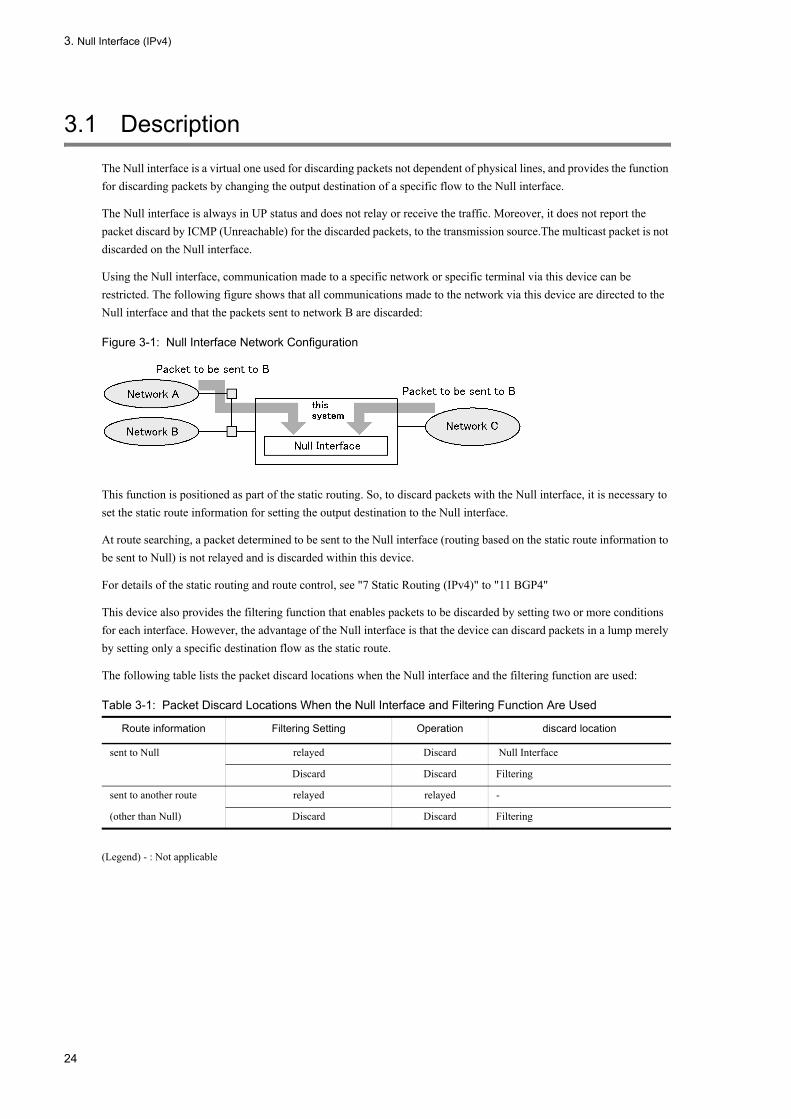
Using the Null interface, communication made to a specific network or specific terminal via this device can be restricted. The following figure shows that all communications made to the network via this device are directed to the Null interface and that the packets sent to network B are discarded:
Figure 3-1: Null Interface Network Configuration
This function is positioned as part of the static routing. So, to discard packets with the Null interface, it is necessary to set the static route information for setting the output destination to the Null interface.
At route searching, a packet determined to be sent to the Null interface (routing based on the static route information to be sent to Null) is not relayed and is discarded within this device.
For details of the static routing and route control, see "7 Static Routing (IPv4)" to "11 BGP4"
This device also provides the filtering function that enables packets to be discarded by setting two or more conditions for each interface. However, the advantage of the Null interface is that the device can discard packets in a lump merely by setting only a specific destination flow as the static route.
The following table lists the packet discard locations when the Null interface and the filtering function are used:
Table 3-1: Packet Discard Locations When the Null Interface and Filtering Function Are Used
(Legend) - : Not applicable
Route information Filtering Setting Operation discard location
sent to Null relayed Discard Null Interface
Discard Discard Filtering
sent to another route relayed relayed -
(other than Null) Discard Discard Filtering
24
3. Null Interface (IPv4)
3.2 Configuration
3.2.1 List of Configuration CommandsThe following table lists the configuration commands of the Null interface (IPv4):
Table 3-2: List of Configuration Commands
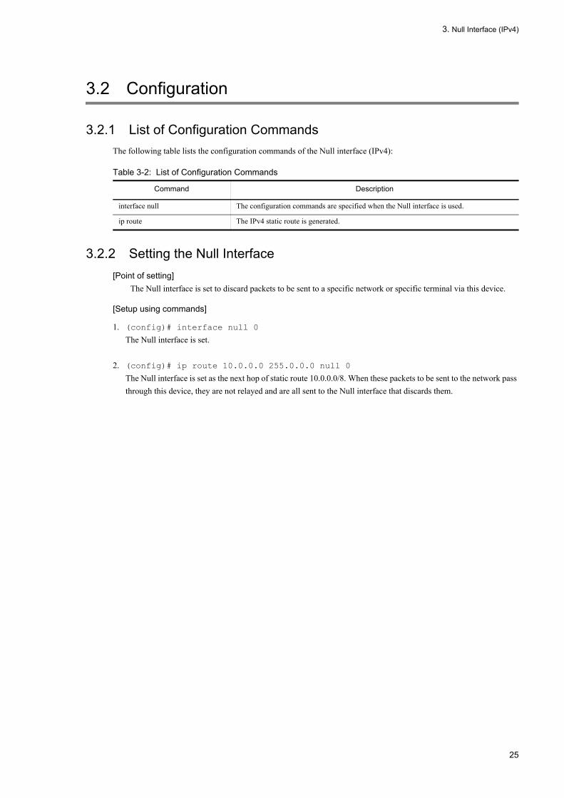
3.2.2 Setting the Null Interface[Point of setting]
The Null interface is set to discard packets to be sent to a specific network or specific terminal via this device.
[Setup using commands]
1. (config)# interface null 0
The Null interface is set.
2. (config)# ip route 10.0.0.0 255.0.0.0 null 0
The Null interface is set as the next hop of static route 10.0.0.0/8. When these packets to be sent to the network pass through this device, they are not relayed and are all sent to the Null interface that discards them.
Command Description
interface null The configuration commands are specified when the Null interface is used.
ip route The IPv4 static route is generated.
25
3. Null Interface (IPv4)
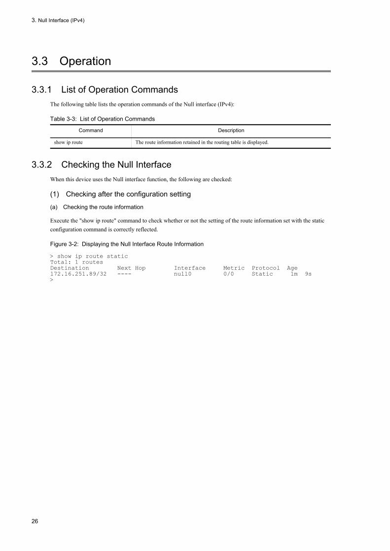
3.3 Operation
3.3.1 List of Operation CommandsThe following table lists the operation commands of the Null interface (IPv4):
Table 3-3: List of Operation Commands
3.3.2 Checking the Null InterfaceWhen this device uses the Null interface function, the following are checked:
(1) Checking after the configuration setting
(a) Checking the route information
Execute the "show ip route" command to check whether or not the setting of the route information set with the static configuration command is correctly reflected.
Figure 3-2: Displaying the Null Interface Route Information
> show ip route staticTotal: 1 routesDestination Next Hop Interface Metric Protocol Age172.16.251.89/32 ---- null0 0/0 Static 1m 9s>
Command Description
show ip route The route information retained in the routing table is displayed.
26
4. DHCP/BOOTP Relay Agent Function
4 DHCP/BOOTP Relay Agent FunctionThis chapter provides explanation, configuration, and checking method of the DHCP/BOOTP relay agent function.
4.1 DHCP/BOOTP Relay Agent Function Overview
4.2 Configuration
4.3 Operation
27

4. DHCP/BOOTP Relay Agent Function
4.1 DHCP/BOOTP Relay Agent Function Overview
The DHCP/BOOTP relay agent function relays DHCP/BOOTP packet broadcasted by the DHCP/BOOTP client (hereafter referred to as client) to the DHCP/BOOTP server (hereafter referred to as server) when the server and client are in the different subnets.
When relaying DHCP/BOOTP packet to the server, set the helper address (IP address of the server set in the configuration or that of a router which can relay the packet to the server's subnet) as the destination IP address.
4.1.1 Support SpecificationsThe support specifications of a DHCP/BOOTP relay agent function in the LANSW module are shown in the table below.
Table 4-1: Support Specifications of DHCP/BOOTP Relay Agent Function
4.1.2 Check Items When Receiving DHCP/BOOTP PacketThe table below shows the check items when a DHCP/BOOTP packet is received.
Table 4-2: Check Items When Receiving DHCP/BOOTP Packet
4.1.3 Setting When RelayingThe table below shows the setting in the DHCP/BOOTP packet when the DHCP/BOOTP relay agent function relays DHCP/BOOTP packets.
Item Specification
Connection configuration • DHCP client accommodated through DHCP relay agent• Accommodated through DHCP relay agent
BOOTP support Supported
DHCP/BOOTP PacketHeader Field
Check Item Handling of Packet When Check Is Invalid
Client to Server Server to Client
BOOTP REQUEST HOPS Must be smaller than the value set with configuration
Discarded Not discarded
Relay agent address Must be directed to the LANSW module
Discarded Discarded
IP header TTL 1 or more Discarded Discarded
IP header source address Network number must not be zero Not discarded Discarded
28

4. DHCP/BOOTP Relay Agent Function
Table 4-3: Setting Items for Relaying DHCP/BOOTP
(Legend) -: Not applicable
* IP broadcast address having the form of 255.255.255.255 or 0.0.0.0.
4.1.4 Note on Using DHCP/BOOTP Relay Agent FunctionA DHCP/BOOTP client gateway address (router option) must be set to the virtual router address using a DHCP/BOOTP server when operating a DHCP/BOOTP relay agent and VRRP function in the same interface.
Packet HeaderField
Setting Conditions Contents to Be Set When Conditions Are Met
Client to Server Server to Client
DHCP/BOOTP header relay agent address
When 0.0.0.0 • When multihome is not set to areception interface, the IP address ofthe reception interface is set.
• When multihome is set to a receptioninterface, the IP address displayedusing an operation command (showdhcp giaddr command) is set.
-
DHCP/BOOTP header broadcast flag
When 1 - Destination IP address is set to conditional broadcast*.
When 0 - Destination IP address is set to client IP address.Destination MAC address is set to client hardware address.
DHCP/BOOTP header BOOTP REQUEST HOPS
When DHCP/BOOTP REQUEST packets are relayed to the DHCP/BOOTP server
Increased by one. -
IP header source address When 0.0.0.0 IP address of transmission interface is set.
-
IP header destination address
When it is a conditional broadcast*
Helper address is set. -
29

4. DHCP/BOOTP Relay Agent Function
4.2 Configuration
4.2.1 List of Configuration CommandsTable below shows the configuration command list of DHCP/BOOTP relay agent.
Table 4-4: List of Configuration Commands
4.2.2 Setting for Basic Configuration[Point of setting]
Set the helper address, which is used as the forwarding address for relaying BOOTP REQUEST packet, in DHCP relay agent.
Figure 4-1: Basic Configuration (One Relay Agent Exists between DHCP/BOOTP Server and DHCP/BOOTP Client)
[Setup using commands]
1. (config)# vlan 2
(config-vlan)# exit
(config)# interface gigabitethernet 0/5
(config-if)# switchport mode access
(config-if)# switchport access vlan 2
(config-if)# exit
(config)# interface vlan 2
(config-if)# ip address 10.1.0.1 255.255.0.0
(config-if)# exit
Sets VLAN ID, line, access port, VLAN interface, and IP address in advance.
2. (config)# vlan 3
(config-vlan)# exit
(config)# interface gigabitethernet 0/7
(config-if)# switchport mode access
Command Description
ip bootp-hops Sets the hops threshold.
ip helper-address Sets the destination address for transfer by DHCP relay agent. In "4.2.2 Setting for Basic Configuration" and "4.2.3 Setting for Multihome Configuration", used to set an IP address of a DHCP/BOOTP server as helper address.
ip relay-agent-address Sets the relay agent address (giaddr) of a DHCP/BOOTP client connection interface. In "4.2.3 Setting for Multihome Configuration", used to set an IP address of Network A as a relay agent address.
30

4. DHCP/BOOTP Relay Agent Function
(config-if)# switchport access vlan 3
(config-if)# exit
(config)# interface vlan 3
(config-if)# ip address 20.1.0.1 255.255.0.0
(config-if)# exit
Same as item 1, sets VLAN ID, line, access port, and IP address in advance for the interface which relays the data to a DHCP/BOOTP server.
3. (config)# interface vlan 2
(config-if)# ip helper-address 20.1.0.10
(config-if)# exit
Sets the IP address of the DHCP/BOOTP server as helper address.
4.2.3 Setting for Multihome Configuration[Point of setting]
In multihome configuration, the primary IP address is used as input interface IP address, while the secondary IP address can be used as input interface by specifying any IP address with relay-agent-address command.Networks B and C in the example below must be the network other than DHCP/BOOTP.
Figure 4-2: Multihome Configuration
[Setup using commands]
1. (config)# vlan 2
(config-vlan)# exit
(config)# interface gigabitethernet 0/3
(config-if)# switchport mode access
(config-if)# switchport access vlan 2
(config-if)# exit
Sets VLAN ID, line, and access port in advance.
2. (config)# interface vlan 2
31

4. DHCP/BOOTP Relay Agent Function
(config-if)# ip address 11.1.0.1 255.255.0.0
(config-if)# ip address 10.1.0.1 255.255.0.0 secondary
(config-if)# ip address 12.1.0.1 255.255.0.0 secondary
(config-if)# exit
This is an example that the IP address of Network B is set as primary and IP address of Network A as secondary.
3. (config)# vlan 3
(config-vlan)# exit
(config)# interface gigabitethernet 0/7
(config-if)# switchport mode access
(config-if)# switchport access vlan 3
(config-if)# exit
(config)# interface vlan 3
(config-if)# ip address 20.1.0.1 255.255.0.0
(config-if)# exit
Same as items 1 and 2, sets VLAN ID, line, access port, and IP address in advance for the interface which relays the data to a DHCP/BOOTP server.
4. (config)# interface vlan 2
(config-if)# ip helper-address 20.1.0.10
Sets the IP address of the DHCP/BOOTP server as helper address.
5. (config-if)# ip relay-agent-address 10.1.0.1
(config-if)# exit
Sets the IP address of Network A as a relay agent address.
[Note]When ip relay-agent-address command is omitted, the relay agent address is the primary IP address which is set for the interface.
32

4. DHCP/BOOTP Relay Agent Function
4.3 Operation
4.3.1 List of Operation CommandsTable below shows the operation command list of DHCP/BOOTP relay agent.
Table 4-5: List of Operation Commands
4.3.2 Checking DHCP/BOOTP Destination IP AddressExecute the show dhcp giaddr command and make sure that the displayed IP address matches the IP address of interface set on the LANSW module to which the DHCP/BOOTP client is connected.
Figure 4-3: Execution Result of show dhcp giaddr Command
>show dhcp giaddr allDHCP GIADDR <vlan 2>: 10.1.0.1
Command Description
show dhcp traffic Displays various statistic information of DHCP/BOOTP relay agent.
clear dhcp traffic Clears the statistical information of relay agent to "0".
show dhcp giaddr Displays the destination IP address of DHCP/BOOTP packets from the DHCP/BOOTP server.
33

4. DHCP/BOOTP Relay Agent Function
34

5. DHCP Server Function
5 DHCP Server FunctionThe DHCP server function dynamically assigns IP address and option information to DHCP clients. This chapter provides explanation and configuration of the DHCP server function.
5.1 DHCP Server Function Overview
5.2 Configuration
5.3 Operation
35

5. DHCP Server Function
5.1 DHCP Server Function Overview
The DHCP server function dynamically assigns IP address and option information to DHCP clients. This section describes the specifications and operation of the DHCP server function.
5.1.1 Support SpecificationsThe support specifications of a DHCP server function in the LANSW module are shown in the table below. The DHCP server and client are connected directly within the same network or through a DHCP relay agent.
Table 5-1: Support Specifications of DHCP Server Function
5.1.2 Information Distributed to ClientsThe table shows a list of information that the LANSW module can distribute to clients. Optional information is not included in the distribution data even if the LANSW module specifies the option to send it unless the client requests it through the option request list.
Table 5-2: Information Distributed to the Client by the LANSW module
Item Specification
Connection configuration • Directly accommodate DHCP client• Accommodated through DHCP relay agent
BOOTP server function Not supported
Dynamic DNS cooperation SupportThe LANSW module supports the dynamic DNS server which uses DNS UPDATE based on RFC 2136.
Dynamic/fixed IP address allocation function Supported
Information Name Description
IP address Set the IP address available to the client.
IP address lease period Set the lease period of the distributed IP address. On the LANSW module, the value is determined from the default-lease-time/max-lease-time parameter and the request from the client. (Option No: 51)
Subnet mask For this option, subnet mask length of network information specified in configuration is used. (Option No: 1)
Router option Specify the IP address of the router on the client's subnet. Specify a list starting from the one with the highest priority. This list is used as the client's gateway address. (Option No: 3)If this option is not specified by the configuration, the router option is not included but, instead, the same value as the IP address to be distributed is set in the router option so that it will be returned to the client.
DNS option Specify the IP address of the domain name server available to the client. Specify a list starting from the one with the highest priority. (Option No: 6)
Host name option Set when the server specifies the client name. The name may be restricted by the local domain name. Specified with character string. (Option No: 12)
Domain name option Specify the domain name used by the client when converting the host name with the domain name system. (Option No: 15)
36

5. DHCP Server Function
5.1.3 Dynamic DNS CooperationThe DHCP server of the LANSW module supports a function to add an entry record to the Dynamic DNS server (DNS update) concurrently with the allocation of IP address. In order to use this function, the target zone and the destination DNS server must be specified, and the DNS server must be configured to enable record update from the LANSW module.
Record update can be enabled by using IP address or an HMAC-MD5 authentication key. Enabling by IP address is accomplished simply by the DNS server allowing access from the IP address or network connected to the DNS server. However, when using an authentication key, the key specified by the DNS server must be set to the DHCP server as the DNS authentication key information.
Notes on dynamic DNS cooperation• DHCP server of the LANSW module performs DNS update of only dynamically assigned IP addresses. Records
must be added to DNS server in advance if distributing with fixed address.• In order to perform DNS update, the DHCP client must return FQDN to the DHCP server at IP address allocation.
If the necessary information is unavailable the DHCP server does not perform DNS update for that lease. For actual setting, see setting of the system used as client.
• When using authentication key for DNS update, the clock of the DNS server and the LANSW module must be synchronized. In most cases, the tolerable time difference is within 5 minutes in UTC. Therefore, synchronize the clock with NTP.
5.1.4 Preventing Duplicated Allocation of IP AddressWhen the LANSW module is restarted after while DHCP server of the LANSW module is in service (address assigned to DHCP client), all IP addresses in the pool of assignable IP addresses will be "available". However, next time the LANSW module assigns an IP address, it prevents duplicate assignment by sending an ICMP echo request packet to the previously assigned IP addresses and checking for a response packet to determine whether it is already used by a client. At the same time, client communication is unaffected because the same IP address is used when assigning IP addresses to previously assigned clients.
Also, if there is a response to the ICMP echo request packet (the IP address is already used by a terminal on the network), a conflicting address detected message is displayed on the result screen of the show ip dhcp conflict command.
5.1.5 Notes on Using DHCP Server FunctionThe note on using the DHCP server function is described below.
(1) IP address of input interface for multihome connection
For multihome connection, primary IP address is used as IP address of the input interface. An IP address is assigned to the DHCP client from the address pool set for this subnet.
NetBIOS over TCP/IP name server option
Specify the NetBIOS name server (WINS server) referenced by the client with a list of IP addresses. Specify a list starting from the one with the highest priority. (Option No: 44)
NetBIOS over TCP/IP node type specification option
Set the node type (NetBIOS name resolution method) of the NetBIOS over TCP/IP client. (Option No: 46)• Code 1: B node (broadcast node)• Code 2: P node (Peer to Peer node (use WINS))• Code 4: M node (mixed node (use WINS if not found by broadcast))• Code 8: H node (hybrid node (use broadcast if not found by WINS))
Information Name Description
37

5. DHCP Server Function
(2) Simultaneous connections for shortened lease time
If the lease time is 10 seconds, maximum connections to the clients should be 200 or less. Likewise, adjust the simultaneous connections for 400 or less for 20 seconds, 600 or less for 30 seconds.
38

5. DHCP Server Function
5.2 Configuration
5.2.1 List of Configuration CommandsTable below shows the configuration command list of DHCP server.
Table 5-3: List of Configuration Commands
Command Description
client-name Specifies host name option to be distributed to the client. Host name option is used as host name to be used by the client for fixed IP address allocation.
default-router Specifies the router option to be distributed to the client. Router option is a list of IP addresses which can be used by the client as the router IP address (default router) on the subnet. As shown in "5.2.2 Setting for Allocating IP to Client", set the IP address of router used by the client.
dns-server Specifies the domain name server option to be distributed to the client. Domain name server option is a list of IP addresses of DNS server which can be used by the client. As shown in "5.2.4 Setting for Dynamic DNS Cooperation", set the IP address of DNS server used by the client.
domain-name Specifies the domain name option to be distributed to the client. Domain name option is used as domain name which should be used by the client when the client performs name resolution for allocated IP address in domain name system. As shown in "5.2.4 Setting for Dynamic DNS Cooperation", set the domain name to be used by the client for host name resolution.
hardware-address Specifies the MAC address of the client System when allocating fixed IP address to the client system. This command is used together with the host command. As shown in "5.2.3 Setting for Allocating Fixed IP to Client", set MAC address of the client.
host Specifies the IP address to be assigned when allocating fixed IP address to the client system. This command is used together with the hardware address command. As shown in "5.2.3 Setting for Allocating Fixed IP to Client", set the IP address used by the client.
ip dhcp dynamic-dns-update Specifies whether to enable dynamic DNS cooperation at the time of IP address allocation. As shown in "5.2.4 Setting for Dynamic DNS Cooperation", set this command in order to enable dynamic DNS cooperation.
ip dhcp excluded-address Specifies the range of IP address not to be allocated, among IP address pools specified with network command. As shown in "5.2.2 Setting for Allocating IP to Client", set the IP address not to be allocated to the client from the network address range.
ip dhcp key Sets the authentication key used for authentication with DNS server when dynamic DNS is used.
ip dhcp pool Sets the DHCP address pool information.
ip dhcp zone Sets the zone information for which DNS is updated, when dynamic DNS is used. As shown in "5.2.4 Setting for Dynamic DNS Cooperation", set the zone information of domain for which cooperation is performed.
lease Specifies default lease time of the IP address to be allocated to the client. As shown in "5.2.2 Setting for Allocating IP to Client", set the leas time of IP address used by the client.
max-lease Specifies the maximum allowable lease time when the client requests IP address with lease time specified.
netbios-name-server Specifies the NetBIOS name server option to be distributed to the client. NetBIOS name server option is an IP address list of NetBIOS name server (NBNS//WINS server) available to the client.
netbios-node-type Specifies the NetBIOS node type option to be distributed to the client. NetBIOS node type option specifies the method by which the client performs name resolution with NetBIOS over TCP/IP.
39
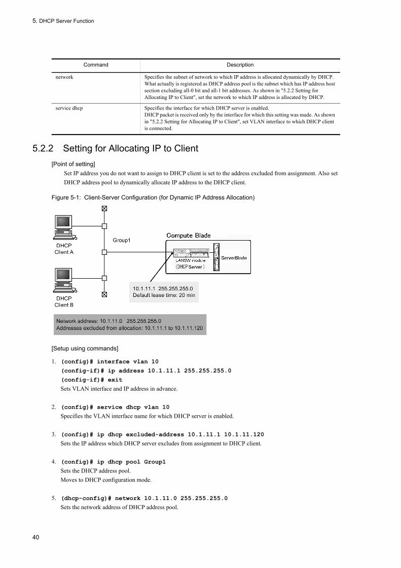
5. DHCP Server Function
5.2.2 Setting for Allocating IP to Client[Point of setting]
Set IP address you do not want to assign to DHCP client is set to the address excluded from assignment. Also set DHCP address pool to dynamically allocate IP address to the DHCP client.
Figure 5-1: Client-Server Configuration (for Dynamic IP Address Allocation)
[Setup using commands]
1. (config)# interface vlan 10
(config-if)# ip address 10.1.11.1 255.255.255.0
(config-if)# exit
Sets VLAN interface and IP address in advance.
2. (config)# service dhcp vlan 10
Specifies the VLAN interface name for which DHCP server is enabled.
3. (config)# ip dhcp excluded-address 10.1.11.1 10.1.11.120
Sets the IP address which DHCP server excludes from assignment to DHCP client.
4. (config)# ip dhcp pool Group1
Sets the DHCP address pool.Moves to DHCP configuration mode.
5. (dhcp-config)# network 10.1.11.0 255.255.255.0
Sets the network address of DHCP address pool.
network Specifies the subnet of network to which IP address is allocated dynamically by DHCP. What actually is registered as DHCP address pool is the subnet which has IP address host section excluding all-0 bit and all-1 bit addresses. As shown in "5.2.2 Setting for Allocating IP to Client", set the network to which IP address is allocated by DHCP.
service dhcp Specifies the interface for which DHCP server is enabled.DHCP packet is received only by the interface for which this setting was made. As shown in "5.2.2 Setting for Allocating IP to Client", set VLAN interface to which DHCP client is connected.
Command Description
40
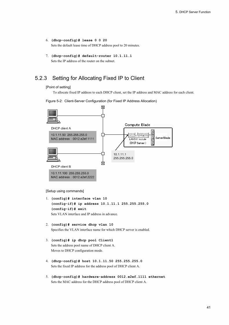
5. DHCP Server Function
6. (dhcp-config)# lease 0 0 20
Sets the default lease time of DHCP address pool to 20 minutes.
7. (dhcp-config)# default-router 10.1.11.1
Sets the IP address of the router on the subnet.
5.2.3 Setting for Allocating Fixed IP to Client[Point of setting]
To allocate fixed IP address to each DHCP client, set the IP address and MAC address for each client.
Figure 5-2: Client-Server Configuration (for Fixed IP Address Allocation)
[Setup using commands]
1. (config)# interface vlan 10
(config-if)# ip address 10.1.11.1 255.255.255.0
(config-if)# exit
Sets VLAN interface and IP address in advance.
2. (config)# service dhcp vlan 10
Specifies the VLAN interface name for which DHCP server is enabled.
3. (config)# ip dhcp pool Client1
Sets the address pool name of DHCP client A.Moves to DHCP configuration mode.
4. (dhcp-config)# host 10.1.11.50 255.255.255.0
Sets the fixed IP address for the address pool of DHCP client A.
5. (dhcp-config)# hardware-address 0012.e2ef.1111 ethernet
Sets the MAC address for the DHCP address pool of DHCP client A.
41
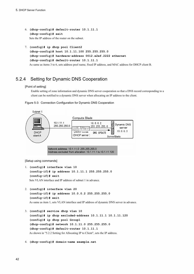
5. DHCP Server Function
6. (dhcp-config)# default-router 10.1.11.1
(dhcp-config)# exit
Sets the IP address of the router on the subnet.
7. (config)# ip dhcp pool Client2
(dhcp-config)# host 10.1.11.100 255.255.255.0
(dhcp-config)# hardware-address 0012.e2ef.2222 ethernet
(dhcp-config)# default-router 10.1.11.1
As same as items 3 to 6, sets address pool name, fixed IP address, and MAC address for DHCP client B.
5.2.4 Setting for Dynamic DNS Cooperation[Point of setting]
Enable setting of zone information and dynamic DNS server cooperation so that a DNS record corresponding to a client can be notified to a dynamic DNS server when allocating an IP address to the client.
Figure 5-3: Connection Configuration for Dynamic DNS Cooperation
[Setup using commands]
1. (config)# interface vlan 10
(config-if)# ip address 10.1.11.1 255.255.255.0
(config-if)# exit
Sets VLAN interface and IP address of subnet 1 in advance.
2. (config)# interface vlan 20
(config-if)# ip address 10.0.0.2 255.255.255.0
(config-if)# exit
As same as item 1, sets VLAN interface and IP address of dynamic DNS server in advance.
3. (config)# service dhcp vlan 10
(config)# ip dhcp excluded-address 10.1.11.1 10.1.11.120
(config)# ip dhcp pool Group1
(dhcp-config)# network 10.1.11.0 255.255.255.0
(dhcp-config)# default-router 10.1.11.1
As shown in "5.2.2 Setting for Allocating IP to Client", sets the IP address.
4. (dhcp-config)# domain-name example.net
42

5. DHCP Server Function
Sets the domain name which should be used by the client when host name resolution is performed in domain name system.
5. (dhcp-config)# dns-server 10.0.0.3
Sets the IP address of DNS server available to the client.
6. (dhcp-config)# exit
Moves to global configuration mode from DHCP configuration mode.
7. (config)# ip dhcp zone example.net. primary 10.0.0.3
Sets zone information for sequential domain example.net., then sets 10.0.0.3 as dynamic DNS server.
8. (config)# ip dhcp zone 11.1.10.in-addr.arpa. primary 10.0.0.3
Sets zone information for reverse domain 11.1.10.in-addr.arpa., then sets 10.0.0.3 as dynamic DNS server.
9. (config)# ip dhcp dynamic-dns-update
Enables dynamic DNS cooperation.
43

5. DHCP Server Function
5.3 Operation
5.3.1 List of Operation CommandsTable below shows the operation command list of DHCP server.
Table 5-4: List of Operation Commands
5.3.2 Checking Allowable Number of IP Addresses to Be AssignedThe number of IP addresses to be assigned to the client is displayed by the result of executing show ip dhcp server statistics command "address pools". Check that this number is greater than that of IP addresses you want to assign to the client.
Figure 5-4: Execution Result of show ip dhcp server statistics Command
> show ip dhcp server statistics < DHCP Server use statistics > address pools :19 automatic bindings :170 manual bindings :1 expired bindings :3 over pools request :0 discard packets :0 < Receive Packets > BOOTREQUEST :0 DHCPDISCOVER :178 DHCPREQUEST :178 DHCPDECLINE :0 DHCPRELEASE :1 DHCPINFORM :0 < Send Packets > BOOTREPLY :0 DHCPOFFER :178 DHCPACK :172 DHCPNAK :6>
Command Description
show ip dhcp binding Displays the binding information on the DHCP server.
clear ip dhcp binding Deletes the binding information from the DHCP server database.
show ip dhcp import Displays the option/ parameter value set by the configuration of DHCP server.
show ip dhcp conflict Displays the collision IP address information detected by the DHCP server. The collision IP address is an IP address that is vacant for the DHCP server pool IP address but already allocated to a terminal on the network. The collision IP address is detected by whether the response of for ICMP packet sent exists before the DHCP server allocates an IP address to the DHCP client.
clear ip dhcp conflict Removes the collision IP address information from the DHCP server.
show ip dhcp server statistics Displays the statistical information on the DHCP server.
clear ip dhcp server statistics Resets the statistical information of the DHCP server.
restart dhcp Restarts the daemon process of the DHCP server.
dump protocols dhcp Outputs the server log and packet transmission/reception log collected by the DHCP server program.
dhcp server monitor Starts the extraction of the transmission/reception log of the packets transmitted and received by a DHCP server.
no dhcp server monitor Stops the extraction of the packet transmission/reception log by DHCP server program.
44

5. DHCP Server Function
5.3.3 Checking Allocated IP AddressesExecute the command "show ip dhcp binding" to check the IP addresses that are actually assigned to the DHCP client. IP addresses that have not expired lease are displayed.
Figure 5-5: Result of Executing show ip dhcp binding Command
> show ip dhcp binding<IP address> <MAC address> <Lease expiration> <Type>10.1.11.1 0012.e2ef.1111 05/09/01 19:39:20 Automatic10.1.11.50 0012.e2ef.2222 Manual>
45

5. DHCP Server Function
46

6. General Description of IPv4 Routing Protocol
Part 2 IPv4 Routing Protocol
6 General Description of IPv4 Routing ProtocolThis chapter describes the IPv4 routing protocols.
6.1 IPv4 Routing Protocol Overview
6.2 General Operation of IPv4 Routing
6.3 Network Design Concept
6.4 Load Balancing Overview
6.5 Configuration of Load Balancing
6.6 Operation of Load Balancing
6.7 Route Aggregation Overview
6.8 Configuration of Route Aggregation
6.9 Operation of Route Aggregation
6.10 Route Deletion Reserve Function
47

6. General Description of IPv4 Routing Protocol
6.1 IPv4 Routing Protocol Overview
6.1.1 Outline of RoutingThe routing protocol exchanges the route information with the neighboring router. The route information learned by each routing protocol is held in the routing table. The optimum route information is registered in the forwarding table as destination. The packet is relayed according to the forwarding table.
Figure 6-1: Outline of Routing
6.1.2 Static Routing and Dynamic RoutingA routing table must be created to relay packets. The methods used to create the routing table of the LANSW module are classified into static routing and dynamic routing.
• Static routingIn this method, the user sets route information using configuration.
• Dynamic routingIn this method, the user replaces route information for other routers in a network and determines the relay route. The LANSW module supports RIP version 1 (hereafter referred to as RIP-1) and version 2 (hereafter referred to as RIP-2), OSPF version 2 (hereafter referred to as OSPF), and BGP version 4 (hereafter referred to as BGP4).
6.1.3 Route InformationThe route information (the type of addresses subject to routing) that the LANSW module handles is shown in the table
48

6. General Description of IPv4 Routing Protocol
below.
Table 6-1: Route Information
6.1.4 Application Scope by Routing ProtocolThe table below shows the application of routing protocols by route information, and additional features supported for these protocols.
Table 6-2: Application Scope by Routing Protocol
Route information Description
Normal route Default route Route to all network (destination address: 0.0.0.0, network mask: 0.0.0.0)
Natural mask route Route of network mask corresponding to address class (network mask: Class A = 8 bits, Class B = 16 bits, Class C = 24 bits)
Subnet route Route to a specific subnet (route that network mask is longer than network mask corresponding to the address class)
Host route Route to a specific host (route that network mask is 32 bits)
Variable-length subnet mask
Handles the VLSM (Variable Length Subnet Mask). In the same network address, multiple subnet masks of different lengths can be handled.
CIDR compatible route Supernet route Handles the route information of a network mask that is shorter than the network mask corresponding to the address class. For example, the route information of the Class C network address, 192.168.8.0/24,192.168.9.0/24,192.168.10.0/24, 192.168.11.0/24 can be aggregated and handled in one supernet route 192.168.8.0/22.
0 subnet route Handles the network address when the subnet number is 0 as one subnetwork. For example, the route information of the Class B network address 172.16.0.0/24 can be handled.
-1 subnet route Handles the network address when the subnet number is -1 (All '1') as one subnetwork. For example, the route information of the Class B network address 172.16.255.0/24 can be handled.
Comprehensive subnet Handles the route when the network address has a comprehensive relationship between individual sets of route information and multiple sets of route information. For example, the Class B network addresses 172.16.3.0/24 and 172.16.2.0/23 are handled as individual sets of route information.
Route Information Routing
Static Dynamic
RIP-1 RIP-2 OSPF BGP4
Route information
Default route Y Y Y Y Y
Natural mask route Y Y Y Y Y
Subnet route Y Y Y Y Y
Host route Y Y Y Y Y
Variable-length subnet mask
Y N Y Y Y
CIDR compliance Y Y/N Y Y Y
Multipath (maximum 16 paths)
Y N N Y Y
49

6. General Description of IPv4 Routing Protocol
(Legend)Y: HandledY/N: Applicable only when the subnet route is 0 or -1N: Not handled-: Not applicable
6.1.5 Simultaneous Operation of Routing ProtocolEach static and dynamic routing protocol can operate simultaneously.
(1) Selecting priority of learned route
When multiple routing protocols operate simultaneously, each of which follows its own route selection procedure to select the best route to a certain destination address from the route information. As a result, the multiple route information to one destination address exists in the LANSW module. In this case, the distance value of each route's information are compared and the route information that has high priority becomes valid.
The LANSW module allows you to define the distance value (the priority) of the route information for every static route or dynamic routing protocol (i.e., RIP) in the configuration. For the distance, a priority with the smaller value becomes high. The following table shows the default distance value for each protocol.
Table 6-3: Default Distance Value
(2) Advertised route
When multiple routing protocols operate simultaneously, the route information that is advertised to each routing protocol is limited to the route information that is learned in the same routing protocol. The route information that is learned in a different routing protocol is not advertised.
The LANSW module provides the route filtering function that can broadcast route information of a specific routing
Route selection - Metric (number of routers in route) Cost (number of routers and line speed)
AS path attribute
Routing loop suppression - Split horizon Y Y
Authentication function - N N Y Y
Route Default Distance Value
Direct-coupled route 0 (fixed value)
Static route 2
BGP4 route learned in external peer 20
OSPF AS internal route 110
OSPF AS external route 110
RIP route 120
Aggregate route 130
BGP4 route learned in internal peer 200
Peer learning route between BGP4 member ASs 200
Route Information Routing
Static Dynamic
RIP-1 RIP-2 OSPF BGP4
50

6. General Description of IPv4 Routing Protocol
protocol on another routing protocol and can filter broadcasts of route information of a specific routing protocol.
For details of route filtering, see "12 Route Filtering (IPv4)".
(a) Route advertising in RIP
RIP-1 and RIP-2 are the same routing protocol. RIP-1 and RIP-2 advertise the route information that they learned.
(b) Route advertising in OSPF
Each OSPF domain operates as a different routing protocol. Therefore, multiple OSPF AS internal routes or OSPF AS external routes originating form different OSPF domain may exist in a single destination address. If the distance value between OSPF routes is the same, the path with the smallest domain number has priority. It is possible to change the default distance value of OSPF AS external routes and internal routes (inter-area routes and intra area routes) by domain.
When route filtering is not used, route is not advertised among multiple OSPF domains in the System one another. To advertise OSPF AS internal or external paths as AS external paths in other OSPF domains, set route filtering.
(c) Route advertising in BGP4
When route filtering is not set, BGP4 route learned from certain AS is advertised to other ASs. In this case, the optimum BGP4 route selected in BGP4 is advertised even if the route with the same destination as BGP4 route exists in routing protocol other than BGP4.
When route filtering is set, the route information to be advertised is that with the highest priority selected by the distance value.
6.1.6 Notes on Concurrent Use of Multiple Protocols
(1) Concurrent operation of OSPF or RIP-2 with RIP-1
OSPF and RIP-2 are routing protocols that handle variable-length subnet mask without recognizing classes A, B, and C of an IP address. RIP-1 assumes the existence of classes A, B, and C and cannot handle a variable-length subnet mask. Therefore, careful attention must be paid when OSPF or RIP-2, and RIP-1 are used together in the same network. The relationship between OSPF and RIP-1 is described below as an example. The relationship between RIP-2 and RIP-1 is also the same as that described above.
(a) When subnet route learned by OSPF is not advertised with RIP-1
When the subnet route to the network meets either of the conditions below, the route is not advertised with RIP-1.
1. The route has a subnet mask length different from the network address used by RIP.2. The route has a network address that is different from the network address used by RIP.
Connection between subnets having different subnet mask lengths
For the LANSW module A in the figure below, the route to Network B is registered in its routing table. At this time, the route of Network B is not advertised to Network A because Network B meets condition 1 mentioned before.
Figure 6-2: Connection between Subnets Having Different Subnet Mask Lengths
51
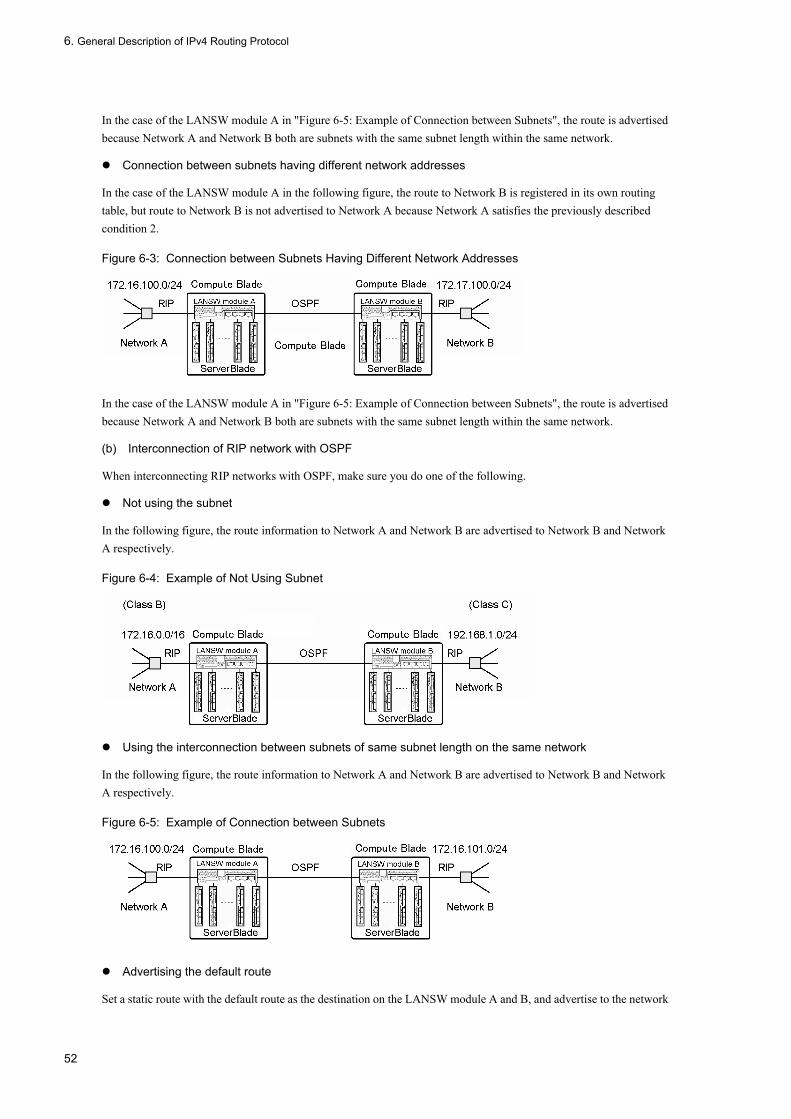
6. General Description of IPv4 Routing Protocol
In the case of the LANSW module A in "Figure 6-5: Example of Connection between Subnets", the route is advertised because Network A and Network B both are subnets with the same subnet length within the same network.
Connection between subnets having different network addresses
In the case of the LANSW module A in the following figure, the route to Network B is registered in its own routing table, but route to Network B is not advertised to Network A because Network A satisfies the previously described condition 2.
Figure 6-3: Connection between Subnets Having Different Network Addresses
In the case of the LANSW module A in "Figure 6-5: Example of Connection between Subnets", the route is advertised because Network A and Network B both are subnets with the same subnet length within the same network.
(b) Interconnection of RIP network with OSPF
When interconnecting RIP networks with OSPF, make sure you do one of the following.
Not using the subnet
In the following figure, the route information to Network A and Network B are advertised to Network B and Network A respectively.
Figure 6-4: Example of Not Using Subnet
Using the interconnection between subnets of same subnet length on the same network
In the following figure, the route information to Network A and Network B are advertised to Network B and Network A respectively.
Figure 6-5: Example of Connection between Subnets
Advertising the default route
Set a static route with the default route as the destination on the LANSW module A and B, and advertise to the network
52
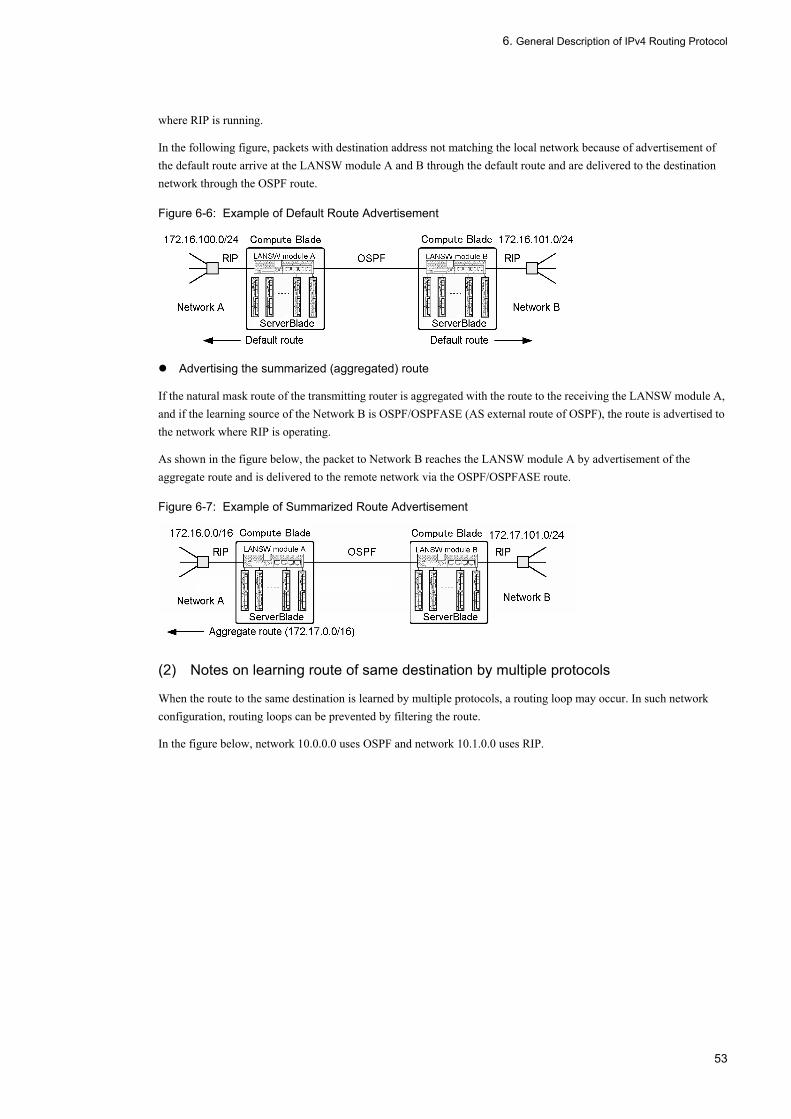
6. General Description of IPv4 Routing Protocol
where RIP is running.
In the following figure, packets with destination address not matching the local network because of advertisement of the default route arrive at the LANSW module A and B through the default route and are delivered to the destination network through the OSPF route.
Figure 6-6: Example of Default Route Advertisement
Advertising the summarized (aggregated) route
If the natural mask route of the transmitting router is aggregated with the route to the receiving the LANSW module A, and if the learning source of the Network B is OSPF/OSPFASE (AS external route of OSPF), the route is advertised to the network where RIP is operating.
As shown in the figure below, the packet to Network B reaches the LANSW module A by advertisement of the aggregate route and is delivered to the remote network via the OSPF/OSPFASE route.
Figure 6-7: Example of Summarized Route Advertisement
(2) Notes on learning route of same destination by multiple protocols
When the route to the same destination is learned by multiple protocols, a routing loop may occur. In such network configuration, routing loops can be prevented by filtering the route.
In the figure below, network 10.0.0.0 uses OSPF and network 10.1.0.0 uses RIP.
53

6. General Description of IPv4 Routing Protocol
Figure 6-8: Network Configuration Example
For the route addressed to network 10.2.0.0, three types are generated:
1. AS external route advertised by Router C ((a) in figure)2. Route advertised from OSPF to RIP ((b) and (c) in figure)3. Route advertised from RIP to OSPF ((d) and (e) in figure)
In this example, when the LANSW module B selects (d) and the LANSW module A selects (c), or the LANSW module A selects (e) and the LANSW module B selects (b), a routing loop (the next hop is destined to each other's router) occurs. In such case, route filtering must be set so that the route to 10.2.0.0 advertised from OSPF to RIP by the LANSW module A or the LANSW module B is not learned as an AS external route from RIP to OSPF.
6.1.7 Notes on Setting/Changing ConfigurationWhen the configuration related with the unicast routing protocol is set/changed, all retained routes are re-evaluated based on the configuration. During route re-evaluation, it may take longer to execute an operation command regarding the unicast routing protocol, or to obtain MIB over SNMP.
54

6. General Description of IPv4 Routing Protocol
6.2 General Operation of IPv4 Routing
6.2.1 List of Operation CommandsTable below shows the list of operation commands common to IPv4 routing.
Table 6-4: List of Operation Commands
6.2.2 Checking Route to Destination AddressMake sure using the command "show ip route" that the route to the destination address exists when IPv4 unicast routing information is set on the LANSW module.
Figure 6-9: Display Example of show ip route Command
> show ip routeDate 2005/07/14 12:00:00 UTCTotal: 13 routesDestination Next Hop Interface Metric Protocol Age172.16/16 192.168.1.100 VLAN0010 2/0 RIP 8s ... 1192.168.1/24 192.168.1.1 VLAN0010 0/0 Connected 8s : :>
1. Check whether the route to the destination address exists.
Command Description
show system Displays the operation state.
ping Sends the test packet to the System with specified IPv4 address, and determines whether communication is possible.
show ip-dual interface (IPv4) Displays the IPv4 and IPv6 interface state.
show ip interface Displays the IPv4 interface state.
show netstat (netstat) (IPv4) Displays the state and statistics of a network.
traceroute Displays the route through which IPv4 datagram is passed to the destination host.
show processes cpu unicast Displays the CPU usage of the unicast routing program.
debug protocols unicast Starts operation message display of the event log information that a unicast routing program outputs.
dump protocols unicast Outputs the trace information and control table information collected by a unicast routing program to a file.
erase protocol-dump unicast Deletes the trace information file and control table information file created by a unicast routing program.
no debug protocols unicast Stops operation message display of the event log information that the unicast routing program outputs.
restart unicast Restarts the unicast routing program.
show ip interface ipv4-unicast Displays the IPv4 interface information of the LANSW module recognized by a unicast routing program.
debug ip Displays the packet sent/received by IPv4 routing protocol in real time.
clear ip route Clears and re-registers hardware IPv4 forwarding entries.
show ip entry Displays detailed information on specific IPv4 unicast route.
show ip route Displays the route information held in the routing table.
55

6. General Description of IPv4 Routing Protocol
6.3 Network Design Concept
This section explains the concept used to design an IPv4 network.
6.3.1 Address DesignIt is desirable to follow the concept described below when using a local address and when there is enough space to assign IP addresses. This makes it possible to avoid many problems and facilitates a comparatively simple network design.
1. Try not to use multiple network addresses. Use a single "large" network address (Class A or Class B) as a subnet free of address boundaries.
2. The number of bits in the subnet mask must be the fixed (must not be variable length subnet mask).
Route advertisement conditions must be considered when routing by RIP-1 without satisfying the addressing conditions in steps 1 and 2 above.
6.3.2 Handling of Direct RouteThe LANSW module handles broadcast type line. For broadcast type line, the direct-connection route is handled as network address (NA) and subnet mask (Mask).
The figure below shows handling of the direct-connection route.
Figure 6-10: Handling of Direct Route
6.3.3 Address Boundary DesignWhen using multiple network addresses, place the address boundary on the LANSW module as shown in the following figure. Address boundary refers to the boundary of the network address corresponding to the natural mask. There is no address class boundary.
Figure 6-11: Normal Address Boundary Design
56
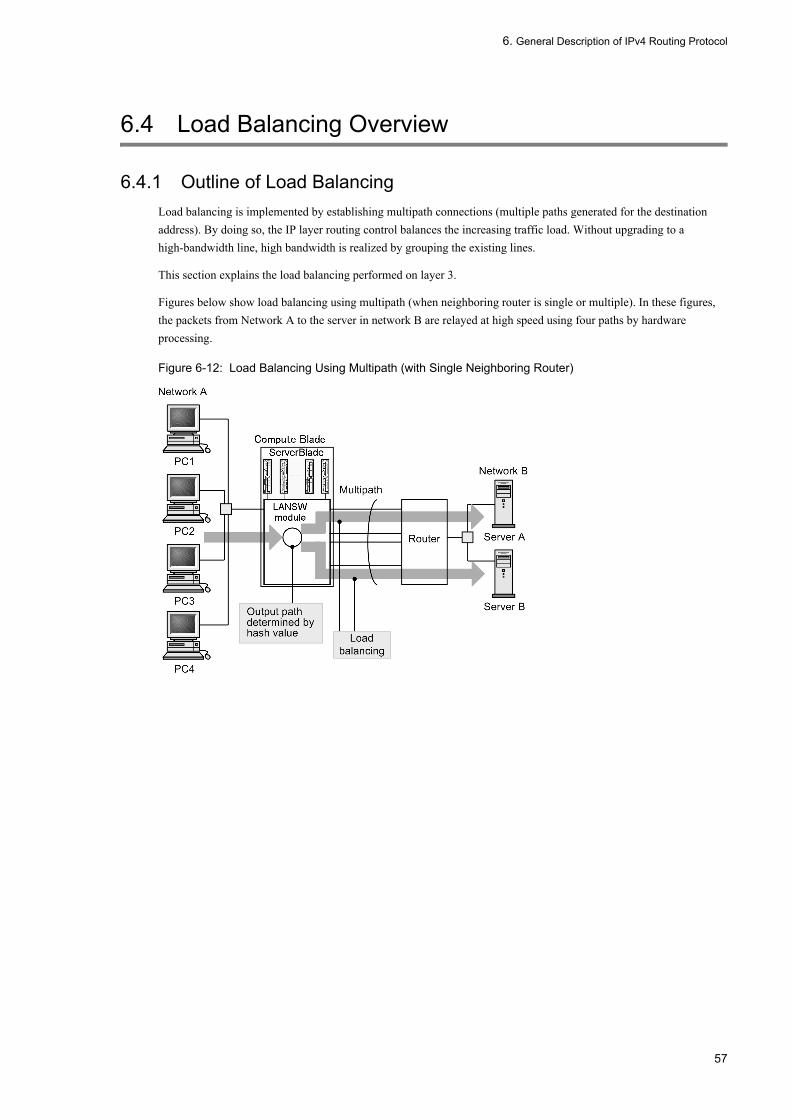
6. General Description of IPv4 Routing Protocol
6.4 Load Balancing Overview
6.4.1 Outline of Load BalancingLoad balancing is implemented by establishing multipath connections (multiple paths generated for the destination address). By doing so, the IP layer routing control balances the increasing traffic load. Without upgrading to a high-bandwidth line, high bandwidth is realized by grouping the existing lines.
This section explains the load balancing performed on layer 3.
Figures below show load balancing using multipath (when neighboring router is single or multiple). In these figures, the packets from Network A to the server in network B are relayed at high speed using four paths by hardware processing.
Figure 6-12: Load Balancing Using Multipath (with Single Neighboring Router)
57

6. General Description of IPv4 Routing Protocol
Figure 6-13: Load Balancing Using Multipath (with Multiple Neighboring Routers)
6.4.2 Load Balancing SpecificationsTable below shows the multipath specification implemented by the LANSW module and the load balancing specification.
Table 6-5: Multipath Specifications
(Legend) -: Not applicable
Item Specification Remarks
Number of multipaths to a single destination network
2 to 16 -
Maximum number of multipaths which can be specified in configuration
1 to 16 (when 1, no multipath is generated) Specified for each routing protocol.
Maximum number of multipath routes 1 to 128 Regardless of number of multipath, up to 128 routes (both IPv4 and IPv6 routes included) can be specified.
Number of routing protocols generated in a multipath.
• Static (IPv4)• OSPF• BGP4
-
Number of multipaths in default configuration
• Static (IPv4): 6• OSPF: 4• BGP4: 1 (multipath is not generated)
-
Connection configuration Can be used regardless of line type and interface type. Coexistence is also permitted.
-
58

6. General Description of IPv4 Routing Protocol
Table 6-6: Load Balancing Specifications
(Legend) -: Not applicable
6.4.3 Notes on Load Balancing1. Because one path is selected uniquely from among 16 paths by using the hash value, the packet distribution ratio for
each path against the destination network is not necessarily uniform.2. When line speed differs, distribution is not processed proportional to the line speed because weighting is not
available. A multihome connection is used for weighting the fast line, but in that case, redundant configuration is required for possible failures.
3. Packet is discarded after trying to send it continuously beyond the output bandwidth of the target path selected by hash value. Such a packet is not re-allocated to the other path.
4. When confirming by traceroute command the selected path to be used for load balancing, pay attention to the following:• Although a response is returned with the IP address of the interface receiving traceroute command as the source
IP address, response is not always returned by using that interface.• When the interface that received the traceroute command has a multihome definition, the response is sent with one
address in the multihome as the source IP address, because distinction of the subnet from which the neighbor system has sent packets is not possible.
5. When communication is concentrated on specific relay route (gateway) while load balancing is used, the relay performance may be significantly lowered. In such case, set static ARP for all relay routes (gateways).
Item Specification Remarks
Determination of multipath An arbitrary value (Hash value) to distribute to 16 paths is calculated and allocated to the designated output path. The order of transmission of each session is guaranteed.
-
Multipath information in routing table The hash allocation ratio of each output interface that is set in a routing table becomes almost equal.
See 1 and 2 in "6.4.3 Notes on Load Balancing".
Weighting of path Not available. See 1 in "6.4.3 Notes on Load Balancing".
Processing of packets exceeding bandwidth
Not reallocated to other path. Queued within the system to a certain extent, and discarded at a queue overflow.
-
59

6. General Description of IPv4 Routing Protocol
6.5 Configuration of Load Balancing
6.5.1 List of configuration commandsThe following table lists the commands used to configure load balancing.
List of configuration commands
#1
See “9 Static Routing (IPv4) in the manual Configuration Commands, Vol. 2”.
#2
See “11 OSPF in the manual Configuration Commands, Vol. 2”.
#3
See “12 BGP4 in the manual Configuration Commands, Vol. 2”.
6.5.2 Configuring the maximum number of multiplepaths handled by the Switch
The maximum number of multipaths used for each protocol in the Switch determines the maximum number of multipaths that the Switch handles and the maximum number of multipath routes that the Switch can accommodate.
The maximum number of multipaths is determined at startup, and any changes made by configuration commands do not take effect until the switch is restarted. If you use a configuration command in a manner that affects the maximum number of multipaths, a warning-level operation message appears prompting you to restart the switch. The new values for the maximum number of multipaths and multipath routes will take effect after the Switch restarts.
[Point of setting]By default, the switch handles a maximum of 16 multipaths. Each multipath can comprise 128 routes. To change the maximum number of multipaths that the switch handles, you must restart the Switch after setting the maximum number of multipaths in the configuration of a unicast routing protocol. For this reason, we recommend that you set the maximum number of multipaths when you first deploy the switch.The configuration below uses an example of IPv4 static routing.
[Setup using commands]
1. (config)# ip route static maximum-paths 2
In configuration mode, sets 2 as the maximum number of multipaths for IPv4 static routes.
2. (config)# ip route 192.168.2.0 255.255.255.0 172.16.1.100 noresolve
(config)# ip route 192.168.2.0 255.255.255.0 172.16.2.100 noresolve
Command name Description
ip route static maximum-paths#1 Specifies the maximum number of paths (maximum number of next hops) that the routing protocol will generate for a static IPv4 route.
maximum-paths (OSPF)#2 When multiple paths (next hops) of equal cost exist for an OSPF-generated route, this command specifies the maximum number of paths in the route.
maximum-paths (BGP4)#3 When multiple routing information entries of equal cost to a given destination exist, this command generates multiple paths using the specified value as the maximum number of paths.
60

6. General Description of IPv4 Routing Protocol
In configuration mode, establishes a static IPv4 multipath route (192.168.2.0/24).
3. (config)# save
(config)# exit
Saves the settings and switches from configuration mode to administrator mode.4. (config)# reload
Restarts the Switch.
6.5.3 Load Balancing Using Static RouteSee "7.2.4 Setting Multipath Route".
6.5.4 Load Balancing Using OSPF See "9.2.6 Setting Multipath".
6.5.5 Load Balancing Using BGP4 See "11.5.3 Configuring BGP4 Multipath (2) Setting BGP4 multipath".
61

6. General Description of IPv4 Routing Protocol
6.6 Operation of Load Balancing
6.6.1 Checking the maximum number of multipaths handled by the Switch
Use the show system command to check the maximum number of multipaths handled by the Switch.
Figure 6-14: Checking the maximum number of multipaths handled by the switch
>show system : : Device resources Current selected swrt_table_resource: l3switch-2 Current selected swrt_multicast_table: On Current selected unicast multipath number: 8 : :>
6.6.2 Checking Selected Path
(1) Checking route information
Execute the show ip route command and check to see if the contents of setting on the multipath route are correctly reflected.
Figure 6-15: Displaying Multipath Route Information
> show ip routeDate 2005/07/14 12:00:00 UTCTotal: 13 routesDestination Next Hop Interface Metric Protocol Age192.168.1/24 192.168.1.1 VLAN0010 0/0 Connected 19m 46s192.168.1.1/32 192.168.1.1 VLAN0010 0/0 Connected 19m 46s192.168.2/24 192.168.2.1 VLAN0020 0/0 Connected 19m 46s192.168.2.1/32 192.168.2.1 VLAN0020 0/0 Connected 19m 46s192.168.3/24 192.168.3.1 VLAN0030 0/0 Connected 19m 46s192.168.3.1/32 192.168.3.1 VLAN0030 0/0 Connected 19m 46s172.16/16 192.168.1.200 VLAN0010 0/0 Static 9s 192.168.2.200 VLAN0020 - - - 192.168.3.200 VLAN0030 - - - : :>
(2) Checking whether communication with destination address is enabled
For the interface of the LANSW module used for load balancing, check to see if communication with the remote system is possible using the ping <IPv4 Address> specific-route source <Source Address> command. For <Source Address> of the command "ping", specify the local IPv4 address on the LANSW module of the interface to be used for load balancing.
62

6. General Description of IPv4 Routing Protocol
6.7 Route Aggregation Overview
6.7.1 Outline of Route AggregationRoute aggregation generates the shorter route information of a network mask that contains applicable route information from one or more sources. This is used to decrease the amount of route information on a network by generating a single route information containing applicable route information from multiple sources and distributing the aggregate route to adjacent routes. For example, when the route information of 172.16.178.0/24 or 172.16.179.0/24 is learned, the consolidated route information 172.16.0.0/16 is generated.
The aggregation must be clearly specified by the configuration command ip summary-address. Distance value can be specified for the aggregated route. When distance value is not specified, default value (130) is used. Aggregated route information is not generated when the aggregation source route information is not learned.
6.7.2 Transfer Method of Aggregated RouteThe aggregated route is a rejection route. If a packet does not have a priority route, it is discarded.
The reason why the aggregated route is a rejection route is to prevent a loop. If the aggregated route were advertised, a packet sent to the aggregation route would be transferred to the LANSW module. In such a case, if the LANSW module transfers a packet without an aggregation source route according to the second-best route such as a default route, a routing loop may occur between the destination system of the default route and the LANSW module. To prevent this situation, the aggregated route is designated as a rejection route.
However, the aggregated route with the noinstall parameter specified does not discard a packet. When the second-best route such as a default route is available, it transfers the packet according to that route. The noinstall parameter is used when it should be better to transfer a packet according to the next-best route rather than discarding on the aggregated route set for advertisement.
6.7.3 Aggregation of AS_PATH AttributeWhen BGP4 route is contained in aggregated source route, path attribute of BGP4 route is added to the aggregated route. When multiple aggregated source BGP4 routes exist, path attributes are aggregated among aggregation source routes. AS_PATH and COMMUNITIES attributes of the aggregated route are edited as follows.
(1) AS_PATH attribute
The section from starting of AS path within AS_SEQUENCE type of AS_PATH attribute, which is common among aggregation source routes, is set to AS_SEQUENCE type of AS_PATH attribute of the aggregated route. For AS path within AS_SEQUENCE type other than above and AS path other than AS_SEQUENCE type, AS_PATH attribute of the aggregated route is set to AS_SET type only when as_set parameter is specified in configuration command ip summary-address.
(2) COMMUNITIES attribute
All communities in aggregation source BGP4 route are set to COMMUNITIES attribute of the aggregated route.
6.7.4 Advertisement Suppression of Aggregation Source RouteAfter route aggregation, it is possible to advertise the aggregated route but exclude the aggregation source route from advertisement. For example, you can advertise RIP routes other than the summarizing source route but not the aggregation source RIP route.
63

6. General Description of IPv4 Routing Protocol
The advertisement suppression of the summarizing source route can be specified for each aggregated route or for all aggregated routes. If specifying for each aggregated route, specify with the summary-only parameter of the configuration command ip summary-address. An example of aggregation source route advertising aggregation is shown in the figure below.
Figure 6-16: Application Example of Aggregation Source Route Advertisement Suppression
System A receives 172.16.1.0/24, 172.16.2.0/24 ... 172.16.20.0/24 from router 1 and 172.17.10/24 from router 2, and learns 172.16.21.0/24, 172.16.22.0/24 ... 172.16.40.0/24 from router 3. System A sets the advertise route filter so as to advertise the aggregated route 172.16.0.0/16 and the learned route 172.17.1.0/24 on router 4. If at this time the definition is made in such a manner that the aggregated route 172.16.0.0/16 is produced from the learned route by designating the summary-only parameter, it is unnecessary to make the setting to suppress the advertisement of the aggregated route on the advertise route filter. Examples of route aggregation configuration and the route before and after route aggregation are shown in the figure below.
Figure 6-17: Configuration Example of Route Aggregation and Route before and after Route Aggregation
64
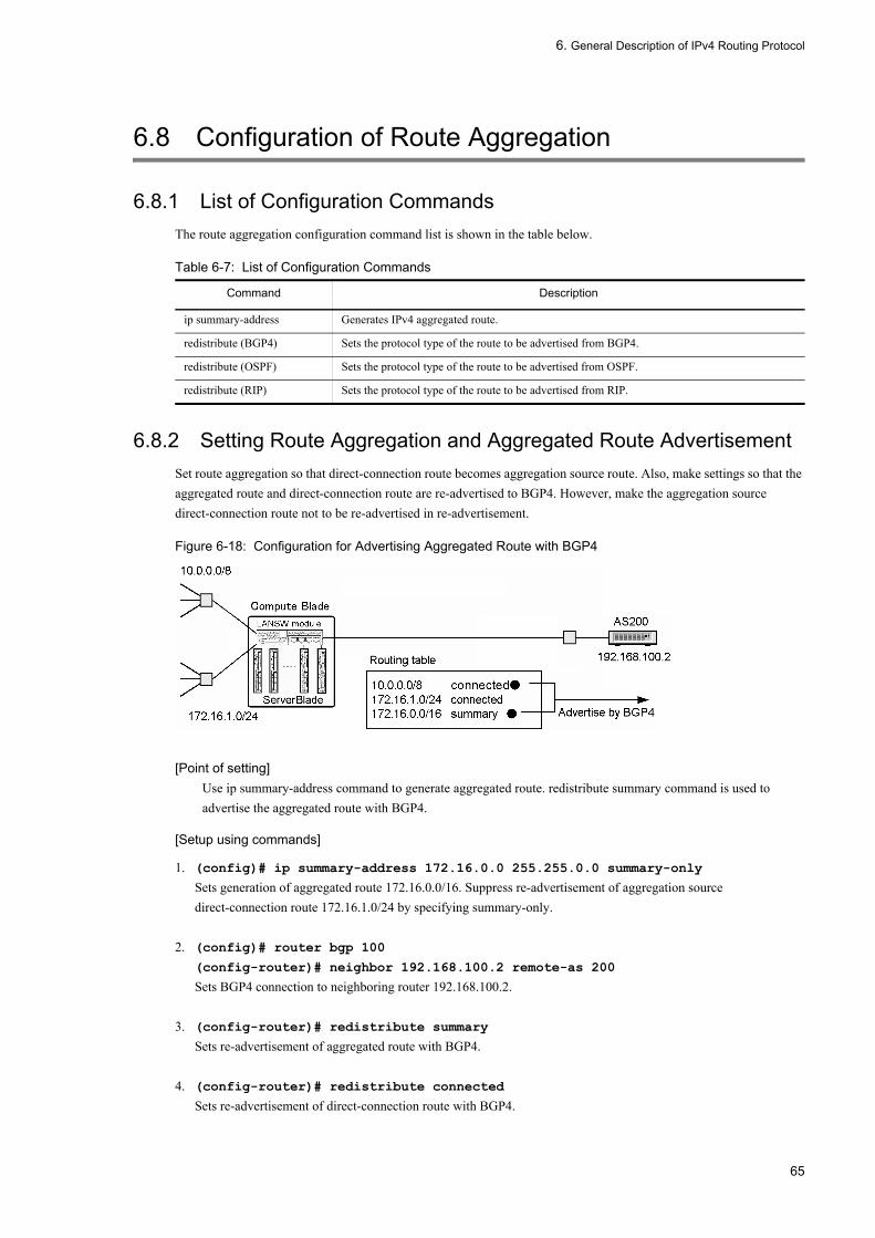
6. General Description of IPv4 Routing Protocol
6.8 Configuration of Route Aggregation
6.8.1 List of Configuration CommandsThe route aggregation configuration command list is shown in the table below.
Table 6-7: List of Configuration Commands
6.8.2 Setting Route Aggregation and Aggregated Route AdvertisementSet route aggregation so that direct-connection route becomes aggregation source route. Also, make settings so that the aggregated route and direct-connection route are re-advertised to BGP4. However, make the aggregation source direct-connection route not to be re-advertised in re-advertisement.
Figure 6-18: Configuration for Advertising Aggregated Route with BGP4
[Point of setting]Use ip summary-address command to generate aggregated route. redistribute summary command is used to advertise the aggregated route with BGP4.
[Setup using commands]
1. (config)# ip summary-address 172.16.0.0 255.255.0.0 summary-only
Sets generation of aggregated route 172.16.0.0/16. Suppress re-advertisement of aggregation source direct-connection route 172.16.1.0/24 by specifying summary-only.
2. (config)# router bgp 100
(config-router)# neighbor 192.168.100.2 remote-as 200
Sets BGP4 connection to neighboring router 192.168.100.2.
3. (config-router)# redistribute summary
Sets re-advertisement of aggregated route with BGP4.
4. (config-router)# redistribute connected
Sets re-advertisement of direct-connection route with BGP4.
Command Description
ip summary-address Generates IPv4 aggregated route.
redistribute (BGP4) Sets the protocol type of the route to be advertised from BGP4.
redistribute (OSPF) Sets the protocol type of the route to be advertised from OSPF.
redistribute (RIP) Sets the protocol type of the route to be advertised from RIP.
65

6. General Description of IPv4 Routing Protocol
6.9 Operation of Route Aggregation
6.9.1 List of Operation CommandsTable below shows the route aggregation operation command list.
Table 6-8: List of Operation Commands
6.9.2 Checking Aggregated RouteDisplay aggregated route information registered in the routing table. An example of display of aggregated route is shown in the figure below.
Figure 6-19: Display Example of Aggregated Route
> show ip route summary_routesDate 2005/07/14 12:00:00 UTCTotal: 1 routesDestination Next Hop Interface Metric Protocol Age172.16/16 ---- - 0/0 Summary 50s
Display the active route contained in specific network (172.16.0.0/16). An example of display of active route is shown in the figure below.
Figure 6-20: Display Example of Active Route
> show ip route 172.16.0.0/16 longer-prefixesDate 2005/07/14 12:00:00 UTCTotal: 3 routesDestination Next Hop Interface Metric Protocol Age172.16/16 ---- - 0/0 Summary 56s172.16.1/24 172.16.1.1 VLAN0010 0/0 Connected 365d172.16.1.1/32 172.16.1.1 VLAN0010 0/0 Connected 365d
Command Description
show ip entry Displays detailed information on specific IPv4 unicast route.
show ip route Displays the route information held in the routing table.
dump protocols unicast Outputs the trace information and control table information collected by a unicast routing program to a file.
erase protocol-dump unicast Deletes the trace information file and control table information file created by a unicast routing program.
restart unicast Restarts the unicast routing program.
show ip bgp Displays BGP protocol information.
show ip ospf Displays OSPF protocol information.
show ip rip Displays RIP protocol information.
66

6. General Description of IPv4 Routing Protocol
6.10 Route Deletion Reserve Function
The route deletion reserve function maintains forwarding using the existing route until an alternate route is newly generated by not deleting the route invalidated using a routing protocol from the routing table for a fixed time. An application example of the route deletion reserve function is shown in the figure below.
Figure 6-21: Application Example of Route Deletion Delay Function
In the figure shown above, the BGP4 route of the LANSW module is temporarily disabled by the peer disconnection between priority router and External AS router A until it is relearned from Non-priority router. However, route information is not deleted from the routing table because a route deletion reserve function is applied. Packet forwarding is maintained through the route below.
[Priority router --> Non-priority router --> External AS router B]
This function is applied when the value in the range of 5 to 4294967295 (seconds) is specified as the route deletion reserve timer value in configuration command routing options delete-delay.
67

6. General Description of IPv4 Routing Protocol
68
7. Static Routing (IPv4)
7 Static Routing (IPv4)This chapter describes the IPv4 static routing.
7.1 Static Routing Overview (IPv4)
7.2 Configuration
7.3 Operation
69

7. Static Routing (IPv4)
7.1 Static Routing Overview (IPv4)
7.1.1 Outline of Static Routing (IPv4)Static routing relays packets according to the route information (the static route) established in the configuration.
For the static route of the LANSW module, multiple relay routes can be set for individual destination (sub) networks including the default route for each device.
The figure below shows a network configuration for static routing. The static route to each branch office is set from the head office, and the static route to the head office is set from the branch office. With this example, communication between the branch offices is not possible.
Figure 7-1: Network Configuration for Static Routing
7.1.2 Route Selection CriteriaIn static routing, multiple static routes having the same destination network are grouped by distance value, and the route is selected from the route group having the smallest distance value.
When the maximum number of multipaths is greater than 1, multiple routes are selected according to the priority shown in the table below in order to configure the multipath. When the maximum number of multipaths is 1, a single route with the highest priority is selected.
Though the maximum number of multipaths is 6 by default, it can be changed by configuration command ip route static maximum-paths.
Table 7-1: Route Selection Priority
Precedence Contents
High Selects the route with the largest weight value.
Low Selects the route with the smallest next hop address.
70

7. Static Routing (IPv4)
7.1.3 Specifying Relay Route of Static RouteFor relay routes (gateways), it is possible to set neighboring gateways that are connected directly and remote gateways that are not directly connected. Neighboring gateways control the creation and deletion of paths to relevant gateways by the state of the directly connected interface. Remote gateways control the creation and deletion of paths depending on whether or not there are paths to the relevant gateways. Default gateway type for the LANSW module is remote gateway. To specify the neighboring gateway in configuration command ip route, noresolve parameter must be specified.
For the above route settings, two types of additional parameters can be selected. These parameters are not to relay a packet.
• noinstall parameterA static route with the noinstall parameter specified is not used for relaying a packet. When the second-best route such as a default route is available, a packet is transferred according to that route. Use the noinstall parameter when it should be better to transfer a packet according to any other route rather than this static route set for advertisement.
• reject parameterA static route with the reject parameter is set as a rejection route. A packet matching the rejection route is discarded. In this case, the source is notified of the packet being discarded due to ICMP (Unreachable). Use the reject parameter when a packet without a priority route over the static route set for advertisement should be discarded. It is also used when a packet should not be transferred to a specific address or destination.
7.1.4 Dynamic Monitoring FunctionAs indicated above, static paths control the creation and deletion of paths according to the state of interfaces directly connected to gateways or whether or not there are paths to the gateways. Therefore, even when paths are created, there is no guarantee that they will reach the gateways. The LANSW module has the function to dynamically monitor the ability of the routes that have been created to reach gateways through cyclic polling using ICMPV4 echo request and echo response messages. In addition to the route creation and deletion conditions described in "7.1.3 Specifying Relay Route of Static Route" above, using this function makes it possible to execute control so that static routes are created only when it is possible to assure that they will reach the relevant gateway.
Even if the relevant gateway changes from unreachable to reachable, a route is not generated at that time. Instead, the reachability to that gateway is monitored for a given period and route is regenerated when it is determined to be stable.
(1) Route switching by dynamic monitoring of static routes
An example of the dynamic monitoring of static is shown in the figure below.
Figure 7-2: Example of Dynamic Monitoring of Static Routes
This figure shows an example of the dynamic monitoring of static routes. In this example, a static route to Network B in System A is set by System C (non-priority) via System B (priority). In the state in which dynamic monitoring is not
71

7. Static Routing (IPv4)
executed, if a malfunction occurs in the interface of System B in the route between Systems A and B, the static route via System B is not deleted since the interface in System A functions normally. Thus, switching to the static route via System C is not performed and communication between Systems A and B is interrupted.
When dynamic monitoring is performed, even if the interface of System A functions normally, dynamic monitoring will make it possible to determine that System B cannot be reached and the static route via System B will be deleted. This makes it possible to assure communication between System A and Network B by switching over to the static route via System C.
(2) Route generation and deletion through dynamic monitoring of static routes and recovery timing
Timing of route generation, deletion, and regeneration through dynamic monitoring of static route depends on the value set in configuration commands ip route static poll-interval and ip route static poll-multiplier.
Hereafter, the value set in ip route static poll-interval is referred to as pollinterval, and values set in ip route static poll-multiplier are referred to as invalidcount and restorecount respectively.
(a) Route generation timing
Gateway polling is executed prompted by interfaces in the up state and other route generation factors. When a response to the relevant polling is received, a route is generated in the next polling cycle (pollinterval). An example of route generation by the dynamic monitoring of static routes is given in the figure below.
Figure 7-3: Route Generation by Dynamic Monitoring of Static Routes
(b) Route deletion timing
The route is deleted if there is no response to polling in the "pollinterval" cycle after successive "invalidcounts". When "invalidcount"=3, the route is deleted if there is no response to polling after 3 attempts in succession. The route is also deleted as same as static routes that do not use polling (poll parameter unspecified) even if interface deactivation and other route generation factors are no longer present. An example of route deletion by dynamic monitoring of static routes is indicated in the figure below.
72

7. Static Routing (IPv4)
Figure 7-4: Route Deletion by Dynamic Monitoring of Static Routes (invalidcount=3)
(c) Route recovery timing
The route is regenerated if there is a response to "pollinterval" cycle polling after successive "restorecount" to the gateway of the route deleted by the dynamic monitoring of static routes. When "restorecount"=2, the route is deleted if there is no response to polling after 2 attempts in succession. An example of route recovery by dynamic monitoring of static routes is indicated in the figure below.
Figure 7-5: Route Regeneration by Dynamic Monitoring of Static Routes (restorecount=2)
73

7. Static Routing (IPv4)
7.2 Configuration
7.2.1 List of Configuration CommandsThe static routing (IPv4) configuration command list is shown in the table below.
Table 7-2: List of Configuration Commands
7.2.2 Setting Default RouteSet a default route for static routing.
[Point of setting]Use ip route command to set the static route. The default route is set by specifying 0.0.0.0 for destination address, and 0.0.0.0 for mask.
[Setup using commands]
1. (config)# ip route 0.0.0.0 0.0.0.0 10.1.1.50
As next hop of the default route, specifies remote gateway 10.1.1.50.
7.2.3 Setting Single-path RouteSet a single-path static route. Priority among multiple routes is adjusted by the distance value.
[Point of setting]For the static route to be set as alternative route, specify the distance value greater than the preferred route.
[Setup using commands]
1. (config)# ip route 192.168.1.0 255.255.255.0 10.1.1.100 100
As next hop of static route 192.168.1.0/24, specifies remote gateway 10.1.1.100. Specifies 100 for distance value.
2. (config)# ip route 192.168.1.0 255.255.255.0 172.16.1.100 200 noresolve
As next hop of static route 192.168.1.0/24, specifies remote gateway 172.16.1.100. Specify 200 for distance value. This route is used as the alternative route when the route to gateway 10.1.1.100 becomes invalid.
7.2.4 Setting Multipath RouteSet a multipath static route.
[Point of setting]Multipath can be established by omitting distance value or specifying the same distance value when setting multiple static routes to the same destination by using ip route command.
Command Description
ip route Generates IPv4 static route.
ip route static poll-interval Specifies the polling interval.
ip route static poll-multiplier Specifies the polling times and successive response times.
74

7. Static Routing (IPv4)
[Setup using commands]
1. (config)# ip route 192.168.2.0 255.255.255.0 172.16.1.100 noresolve
As next hop of static route 192.168.2.0/24, specifies remote gateway 172.16.1.100.
2. (config)# ip route 192.168.2.0 255.255.255.0 172.16.2.100 noresolve
As next hop of static route 192.168.2.0/24, specifies remote gateway 172.16.2.100. Static route 192.168.2.0/24 builds multipath between neighboring gateways 172.16.1.100 and 172.16.2.100.
7.2.5 Applying Dynamic Monitoring FunctionAfter adjusting polling interval and route deletion/generation timing for the gateway to be monitored, the dynamic monitoring function is applied to the static route.
[Point of setting]Use ip route static poll-interval and ip route static poll-multiplier commands to set the polling interval and polling times. To apply the dynamic monitoring function to the static route, specify poll parameter in ip route command.
[Setup using commands]
1. (config)# ip route static poll-interval 10
Specifies 10 seconds for the polling interval of the dynamic monitoring function.
2. (config)# ip route static poll-multiplier 4 2
Specifies 4 for successive failure times (invalidcount), and 2 for successive response times (restorecount) of the dynamic monitoring function.
3. (config)# ip route 192.168.3.0 255.255.255.0 10.2.1.100 poll
(config)# ip route 192.168.4.0 255.255.255.0 10.2.1.101 poll
Applies the dynamic monitoring function to static route 192.168.3.0/24 and 192.168.4.0/24.
75

7. Static Routing (IPv4)
7.3 Operation
7.3.1 List of Operation CommandsTable below shows the static routing (IPv4) operation command list.
Table 7-3: List of Operation Commands
7.3.2 Checking Route InformationCheck the static route information.
Figure 7-6: Execution Result of show ip static route Command
> show ip static routeDate 2005/07/14 12:00:00 UTCStatus Codes: * valid, > active Destination Next Hop Distance Weight Status Flag*> default 10.1.1.50 2 0 IFdown -*> 192.168.1/24 10.1.1.100 100 0 Act -* 192.168.1/24 172.16.1.100 200 0 Act NoResolve*> 192.168.2/24 172.16.1.100 2 0 Act NoResolve 172.16.2.100 2 0 Act NoResolve*> 192.168.3/24 10.2.1.100 2 0 Act Reach Poll 192.168.4/24 10.2.1.101 2 0 UnReach Poll
[Point of checking]1. For the route set in the routing table, "*" and ">" are displayed as Status Codes at the head of line.2. For the alternative route not set in the routing table, ">" is not displayed as Status Codes, but "*" is displayed if
it is a valid route.3. For the invalid route for which "*" and ">" are not displayed as Status Codes, some failure cause is displayed
as Status. "IFdown" indicates that the route becomes invalid because of interface failure. "UnReach" indicates that reachability is not confirmed by the dynamic monitoring function.
Command Description
ping Sends the test packet to the System with specified IPv4 address, and determines whether communication is possible.
show ip interface Displays the IPv4 interface state.
show netstat (netstat) (IPv4) Displays the state and statistics of a network.
traceroute Displays the route through which IPv4 datagram is passed to the destination host.
dump protocols unicast Outputs the trace information and control table information collected by a unicast routing program to a file.
erase protocol-dump unicast Deletes the trace information file and control table information file created by a unicast routing program.
restart unicast Restarts the unicast routing program.
show ip interface ipv4-unicast Displays the IPv4 interface information of the LANSW module recognized by a unicast routing program.
clear ip route Clears and re-registers hardware IPv4 forwarding entries.
show ip entry Displays detailed information on specific IPv4 unicast route.
show ip route Displays the route information held in the routing table.
show ip static Displays information on static route.
clear ip static-gateway Polls the gateway of a route invalidated by the dynamic monitoring of a static route and creates a route if a response is made.
76

7. Static Routing (IPv4)
7.3.3 Checking Gateway InformationCheck the information on the gateway of the static route.
Figure 7-7: Execution Result of show ip static gateway Command
> show ip static gatewayDate 2005/07/14 12:00:00 UTCGateway Status Success Failure Transition10.1.1.50 IFdown - - -10.1.1.100 - - - - 10.2.1.100 Reach - 0/4 13m 39s10.2.1.101 UnReach 1/2 - 21s172.16.1.100 - - - -172.16.2.100 - - - -
[Point of checking]1. For the gateway subject to dynamic monitoring, the reachability state is displayed as Status. If the reachability
is confirmed, "Reach" is displayed, and if not, "UnReach" is displayed.2. When the reachability is not confirmed ("UnReach" is displayed as Status), confirm the monitoring status of the
gateway by Success counter. In execution result shown above, Success counter of gateway 10.2.1.101 is displayed as "1/2". This means that the reachability is confirmed by successive 2 responses and one response has succeeded at present.
77

7. Static Routing (IPv4)
78

8. RIP
8 RIPThis chapter describes RIP of the IPv4 routing protocol.
8.1 RIP Overview
8.2 Configuration
8.3 Operation
79
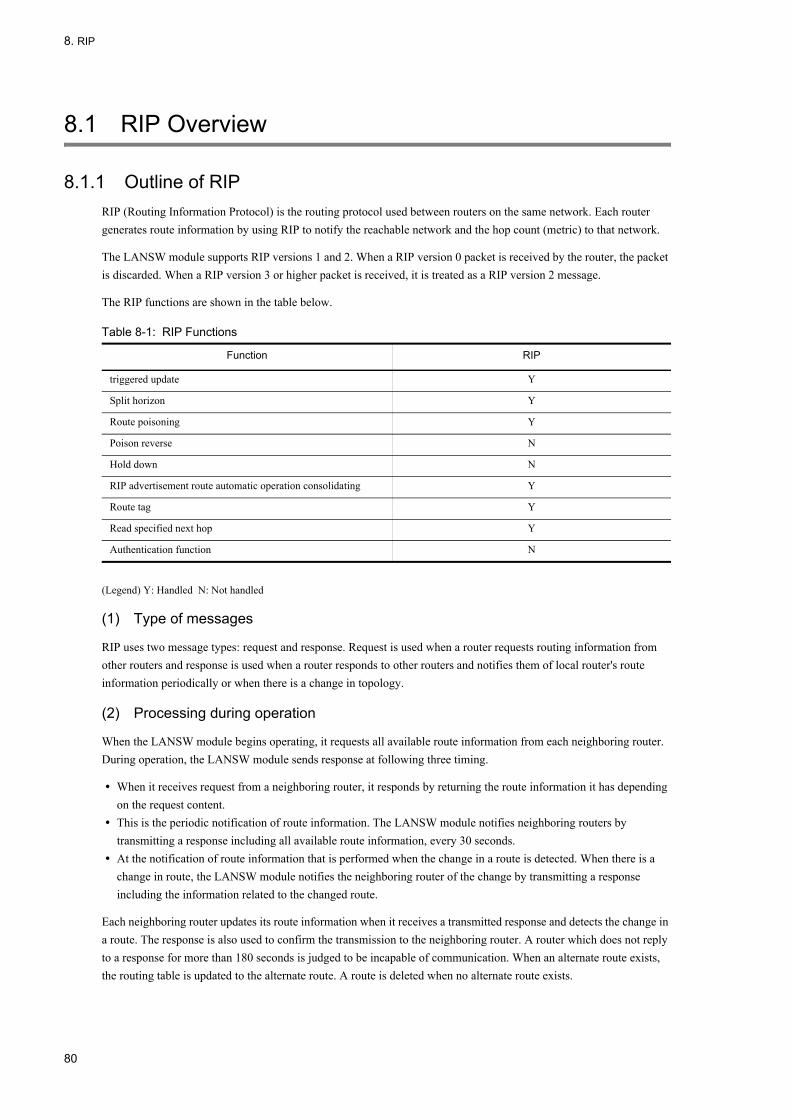
8. RIP
8.1 RIP Overview
8.1.1 Outline of RIPRIP (Routing Information Protocol) is the routing protocol used between routers on the same network. Each router generates route information by using RIP to notify the reachable network and the hop count (metric) to that network.
The LANSW module supports RIP versions 1 and 2. When a RIP version 0 packet is received by the router, the packet is discarded. When a RIP version 3 or higher packet is received, it is treated as a RIP version 2 message.
The RIP functions are shown in the table below.
Table 8-1: RIP Functions
(Legend) Y: Handled N: Not handled
(1) Type of messages
RIP uses two message types: request and response. Request is used when a router requests routing information from other routers and response is used when a router responds to other routers and notifies them of local router's route information periodically or when there is a change in topology.
(2) Processing during operation
When the LANSW module begins operating, it requests all available route information from each neighboring router. During operation, the LANSW module sends response at following three timing.
• When it receives request from a neighboring router, it responds by returning the route information it has depending on the request content.
• This is the periodic notification of route information. The LANSW module notifies neighboring routers by transmitting a response including all available route information, every 30 seconds.
• At the notification of route information that is performed when the change in a route is detected. When there is a change in route, the LANSW module notifies the neighboring router of the change by transmitting a response including the information related to the changed route.
Each neighboring router updates its route information when it receives a transmitted response and detects the change in a route. The response is also used to confirm the transmission to the neighboring router. A router which does not reply to a response for more than 180 seconds is judged to be incapable of communication. When an alternate route exists, the routing table is updated to the alternate route. A route is deleted when no alternate route exists.
Function RIP
triggered update Y
Split horizon Y
Route poisoning Y
Poison reverse N
Hold down N
RIP advertisement route automatic operation consolidating Y
Route tag Y
Read specified next hop Y
Authentication function N
80

8. RIP
(3) Suppression of routing loop
The LANSW module uses split horizon to suppress relay route loops. With split horizon, the received information is not transmitted back to the interface that originally received the information.
8.1.2 Route Selection CriteriaThe LANSW module selects the best route to the same destination learned by each protocol according to independent route selection procedure. When multiple routes to the same destination exists, the distance value for each routing protocol is compared. The routing protocol with the highest priority is selected.
With RIP, the best route is selected according to the route selection priority from route information to the same destination with different advertising source learned using its own protocol. The route selection priority is shown in the table below.
Table 8-2: Route Selection Priority
* This condition is used to learn route information for which the next hop address in the route information is the same from different neighboring systems within the same network.
Then, when multiple route to the same destination exist in the route learned by each protocol (OSPF, BGP4, and static), the priority value of each route information is compared. The route information with highest priority is set to the routing table.
(1) Secondary route generation
Up to two routes (primary route and secondary route) to the same destination learned from different neighboring systems are generated by specifying configuration command generate-secondary-route. The table below shows the condition for generating secondary route.
Table 8-3: Conditions of Secondary Route Generation
(Legend) Y: Configuration available N: Configuration unavailable -: Not applicable
When generation of secondary route is specified, the priority of route information to the same destination is determined according to the following table.
Precedence Contents
High↑
↓Low
Selects the route with the smallest metric value.
Selects route with aging time within 1/2 seconds of the timer value (when metric is the same).
Selects the route with the smallest next hop address.
Selects route for which the next hop address in the route information match the source gateway address of the route information.*
In cases other than the above, ignores the newly learned route.
Condition Secondary Route Generation
Configuration Commandgenerate-secondary-route Specified
Distance Value
N - Not generated
Y Value of primary route and secondary route differs
Not generated
Y Values of primary route and secondary route are the same
Generated
81

8. RIP
Table 8-4: Route Selection Priority When Registration of Secondary Route Is Specified
NoteWhen the next hop address is the same, only the primary route is generated.
*1This condition does not apply when a new route is learned with the secondary route registered.
*2This condition is used to learn route information for which the next hop address in the route information is the same from different neighboring systems within the same network.
8.1.3 Advertising Route Information
(1) Route subject to advertisement
(a) Learning source protocol
For RIP, learned RIP routes and direct-connection routes within RIP-operating network are advertised when a route advertisement filter is not set. When a route advertisement filter is set, advertisement is executed according to the corresponding filtering operation. Table below lists the learning protocols subject to the advertisement for RIP.
Table 8-5: Learning Source Protocol to Be Advertised
*1Secondary address is also advertised.
Precedence Contents
High↑
↓Low
Selects the route with small metric value.
Selects route with aging time within 1/2 seconds of the timer value (when metric is the same).
Selects a route with small next hop address.*1
Selects route for which the next hop address in the route information match the source gateway address of the route information.*2
Selects the route that was the primary route.
In cases other than the above, ignores the newly learned route.
Learning Source Protocol Advertisement Operation without
Route Advertisement Filter
Setting
Order in Which Advertised Metric Is Applied*5
Direct-connection route*1
Within RIP-operating network
Advertised 1. Value specified for route advertisement filter2. Default value (metric value: 1)
Outside RIP-operating network
Not advertised
Aggregate route Not advertised
Static route Not advertised 1. Value specified for route advertisement filter2. Value specified for default-metric3. Default value (metric value: 1)
RIP*2 Advertised 1. Value specified for route advertisement filter2. Value in routing table
OSPF Not advertised 1. Value specified for route advertisement filter2. When inherit-metric is set, value in routing table*3
3. Value specified for default-metric*4BGP Not advertised
82

8. RIP
*2Split horizon is applied.
*3When metric value in the routing table is 16 or greater, the route is not advertised.
*4When route advertisement filter is not specified or metric is not specified in inherit-metric or default-metric, the route is not advertised.
*5When metric-offset out command is set, the value specified for metric-offset out command is added to the selected metric value. When metric value becomes 16 or greater as a result of addition, the route is not advertised.
(b) Address type
Table below shows address type to be advertised with RIP.
Table 8-6: Address Type to Be Advertised
(Legend) Y: Enabled N: Disabled Y/N: Partially enabled* With RIP-1, the subnet route which can be advertised is restricted. For details, see "8.1.5 RIP-1, (1) RIP-1 routing information advertisement".*2 When the "auto-summary" configuration command is set, the advertising subnet channel information is automatically integrated into a single piece of natural mask channel information for advertisement. For details, see (4) Automatically Integrating RIP Advertising Route.
(2) Destination of route information advertisement
With RIP, route information is advertised to all neighboring routers on the network specified by configuration command network. Advertisement can be restricted to specific neighboring routers by setting configuration command neighbor. Table below shows destination to which route information is advertised with RIP.
Address Type Definition Example Advertisement Enabled/Disabled
RIP-1 RIP-2
Default route information
Route information to all networks.
0.0.0.0/0 Y Y
Natural mask route information
Route information of network mask corresponding to the IP address class(Class A: 8 bits)(Class B: 16 bits)(Class C: 24 bits)
172.16.0.0/16• Class B• Net mask: 16 bits
(255.255.0.0)
Y Y
Subnet route information
Route information to the specific subnet
172.16.10.0/24• Class B• Net mask: 24 bits
(255.255.255.0)
Y/N**2 Y*2
Supernet route information
Route information which includes multiple networks
172.0.0.0/8• Class B• Net mask: 8 bits
(255.0.0.0)
N Y
Host route information
Route information to the specific host
172.16.10.1/32• Net mask: 32 bits
(255.255.255.255)
Y Y
83

8. RIP
Table 8-7: Destination of Route Information Advertisement
*1 Advertisement is suppressed for the interface for which passive-interface is specified.*2 Secondary address is also subjected.*3 Neighboring router must be contained in RIP-operating network.
(3) Advertisement timing of route information
The timing of route advertising relates to the following functions in the table below.
Table 8-8: Timing of Route Advertisement
(a) Periodic route information advertisement
RIP periodically advertises the local system's route information to neighboring routers. The figure below shows an example of periodic route information advertisement.
Figure 8-1: Periodic Route Information Advertisement
(b) triggered update
Distributes the route information without waiting for the periodic distribution interval when recognizing change in the local system's route information. The following figure shows the advertisement of route information by triggered update.
Advertisement Destination Destination Address
RIP-operating network*1*2 Multicast address (RIP-2) or subnet broadcast address (RIP-1)
Specific neighboring router*3 Unicast address
Function Contents
Periodic route information advertisement Periodically notifies local system's route information to neighboring router.
triggered update Performs notification without waiting for periodic advertising when there is a change in route information in the local system.
Response to the request from neighboring router Performs notification to the neighboring router which sent the request packet.
Route poisoning Notifies the neighboring routers for a certain period that the route information is deleted.
84
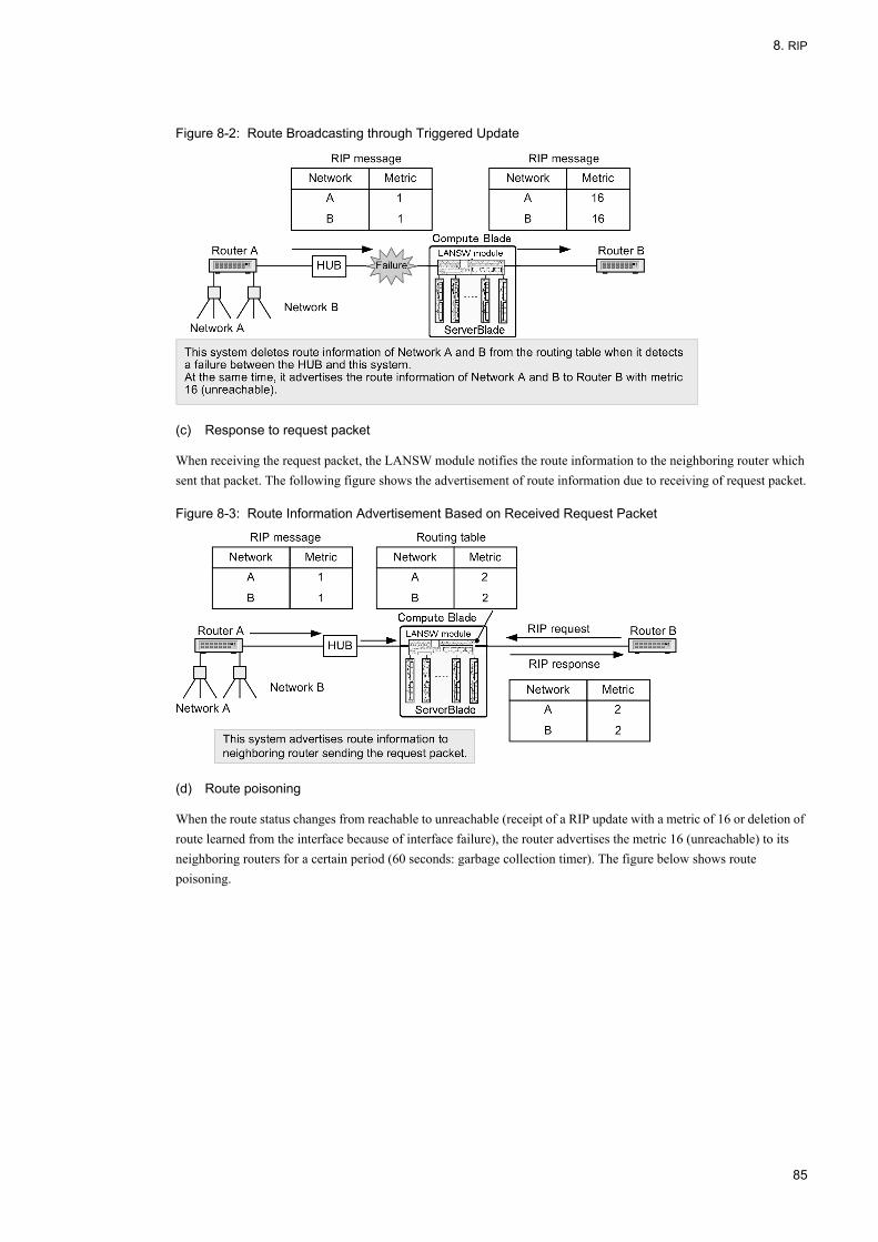
8. RIP
Figure 8-2: Route Broadcasting through Triggered Update
(c) Response to request packet
When receiving the request packet, the LANSW module notifies the route information to the neighboring router which sent that packet. The following figure shows the advertisement of route information due to receiving of request packet.
Figure 8-3: Route Information Advertisement Based on Received Request Packet
(d) Route poisoning
When the route status changes from reachable to unreachable (receipt of a RIP update with a metric of 16 or deletion of route learned from the interface because of interface failure), the router advertises the metric 16 (unreachable) to its neighboring routers for a certain period (60 seconds: garbage collection timer). The figure below shows route poisoning.
85

8. RIP
Figure 8-4: Route Poisoning
During the route poisoning period, if the router receives a RIP update of a new destination route, the router broadcasts the new route information. Relearning during route poisoning period is shown in the figure below.
Figure 8-5: Relearning during Route Poisoning
(4) Automatically Integrating RIP Advertising Route
With the RIP, if you set the "auto-summary" configuration command, it is possible to automatically integrate multiple pieces of subnet channel information advertised to neighboring devices into a single piece of natural mask channel information for advertisement. This configuration command is effective for both RIP-1 and RIP-2.
The following table shows the address types handled as the target of automatic integration for advertising route.
Table 8-9: Address Types Handled as the Target of Automatic Integration for Advertising Route
Address Type Whether address type integration is possible
RIP-1 RIP-2
Default Route information N N
86

8. RIP
(Legend) Y: Integration is possible N: Integration is not possible
*1 If the natural network for advertising Route information is the same as the natural network for the destination interface and if the mask length for the advertising Route information is the same as the mask length for the destination interface, RIP-1 does not perform automatic integration but advertises the subnet Route information to the neighboring devices. For details, see Figure 7-6, "Automatically Integrating Advertising Route When RIP-1 Is Used"
*2 If the natural network for advertising Route information is the same as the natural network for the destination interface, RIP-2 does not perform automatic integration but advertises the subnet Route information to the neighboring devices. For details, see Figure 7-7, "Automatically Integrating Advertising Route When RIP-2 Is Used".
The following figure shows how to automatically integrate subnet Route when RIP-1 is used.
Figure 8-6: Automatically Integrating Advertising Route When RIP-1 Is Used
The following figure shows how to automatically integrate subnet Route when RIP-1 is used.
Natural mask Route information N N
Subnet Route information Y*1 Y*2
Supernet Route information N N
Host Route information N N
Address Type Whether address type integration is possible
87
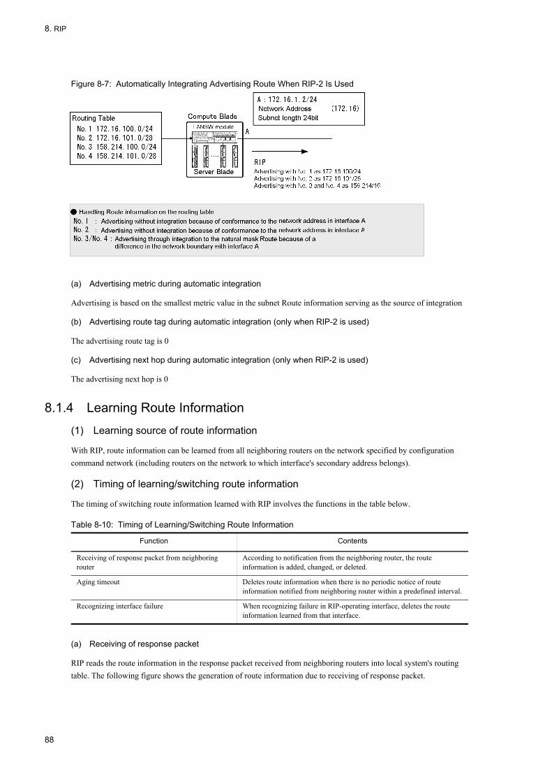
8. RIP
Figure 8-7: Automatically Integrating Advertising Route When RIP-2 Is Used
(a) Advertising metric during automatic integration
Advertising is based on the smallest metric value in the subnet Route information serving as the source of integration
(b) Advertising route tag during automatic integration (only when RIP-2 is used)
The advertising route tag is 0
(c) Advertising next hop during automatic integration (only when RIP-2 is used)
The advertising next hop is 0
8.1.4 Learning Route Information
(1) Learning source of route information
With RIP, route information can be learned from all neighboring routers on the network specified by configuration command network (including routers on the network to which interface's secondary address belongs).
(2) Timing of learning/switching route information
The timing of switching route information learned with RIP involves the functions in the table below.
Table 8-10: Timing of Learning/Switching Route Information
(a) Receiving of response packet
RIP reads the route information in the response packet received from neighboring routers into local system's routing table. The following figure shows the generation of route information due to receiving of response packet.
Function Contents
Receiving of response packet from neighboring router
According to notification from the neighboring router, the route information is added, changed, or deleted.
Aging timeout Deletes route information when there is no periodic notice of route information notified from neighboring router within a predefined interval.
Recognizing interface failure When recognizing failure in RIP-operating interface, deletes the route information learned from that interface.
88
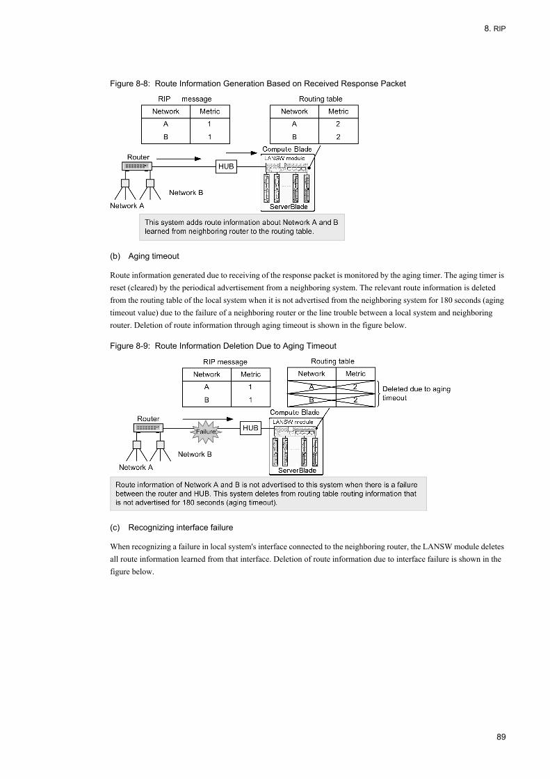
8. RIP
Figure 8-8: Route Information Generation Based on Received Response Packet
(b) Aging timeout
Route information generated due to receiving of the response packet is monitored by the aging timer. The aging timer is reset (cleared) by the periodical advertisement from a neighboring system. The relevant route information is deleted from the routing table of the local system when it is not advertised from the neighboring system for 180 seconds (aging timeout value) due to the failure of a neighboring router or the line trouble between a local system and neighboring router. Deletion of route information through aging timeout is shown in the figure below.
Figure 8-9: Route Information Deletion Due to Aging Timeout
(c) Recognizing interface failure
When recognizing a failure in local system's interface connected to the neighboring router, the LANSW module deletes all route information learned from that interface. Deletion of route information due to interface failure is shown in the figure below.
89
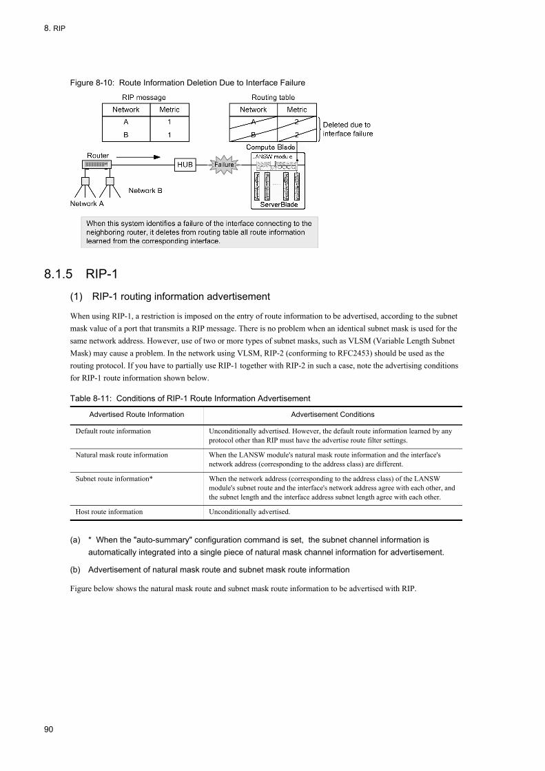
8. RIP
Figure 8-10: Route Information Deletion Due to Interface Failure
8.1.5 RIP-1
(1) RIP-1 routing information advertisement
When using RIP-1, a restriction is imposed on the entry of route information to be advertised, according to the subnet mask value of a port that transmits a RIP message. There is no problem when an identical subnet mask is used for the same network address. However, use of two or more types of subnet masks, such as VLSM (Variable Length Subnet Mask) may cause a problem. In the network using VLSM, RIP-2 (conforming to RFC2453) should be used as the routing protocol. If you have to partially use RIP-1 together with RIP-2 in such a case, note the advertising conditions for RIP-1 route information shown below.
Table 8-11: Conditions of RIP-1 Route Information Advertisement
(a) * When the "auto-summary" configuration command is set, the subnet channel information is automatically integrated into a single piece of natural mask channel information for advertisement.
(b) Advertisement of natural mask route and subnet mask route information
Figure below shows the natural mask route and subnet mask route information to be advertised with RIP.
Advertised Route Information Advertisement Conditions
Default route information Unconditionally advertised. However, the default route information learned by any protocol other than RIP must have the advertise route filter settings.
Natural mask route information When the LANSW module's natural mask route information and the interface's network address (corresponding to the address class) are different.
Subnet route information* When the network address (corresponding to the address class) of the LANSW module's subnet route and the interface's network address agree with each other, and the subnet length and the interface address subnet length agree with each other.
Host route information Unconditionally advertised.
90

8. RIP
Figure 8-11: Natural Mask Route and Subnet Mask Route Information to Be Advertised with RIP
The advertising conditions in this figure are described in the table below.
Table 8-12: Conditions of Natural Mask Route and Subnet Mask Route Advertisement
(Legend) Y: Advertised N: Not advertised -: Not applicable
(c) Notes on advertisement of subnet route information
In the LANSW module, the natural mask route information of each interface IP address is not generated automatically, but only subnet route information is generated. With RIP-1, when the routers belong to different networks, the subnet route information is not advertised. The figure below shows an example of this case.
Figure 8-12: Configuration Example Where Direct Connection Route Is Not Advertised
Note the following configuration:
Route Information Type
Route Information in Routing Table
Advertisement Conditions Application of
AdvertisingMatching with Network Address of Interface D
Matching with Subnet Length of Interface D
Natural mask route 172.16.0.0/16(No.1) Match - N
172.17.0.0/16(No.4) No match - Y
Subnet route 172.17.1.0/24(No.5) No match Match N
172.16.2.0/24(No.2) Match Match Y
172.16.3.0/28(No.3) Match No match N
91

8. RIP
• Routing protocol is RIP-1.• The "auto-summary" configuration command is not set.• Address boundary is generated on the LANSW module.• Interface's subnet mask is not natural mask.
Action 1• Set route aggregation (aggregate subnet route information and host route to natural mask route information) in
the configuration.• Set advertise route filter (re-distributing aggregate route to RIP) in configuration.
Action 2• Set to generate the direct-connection route with natural mask corresponding to subnetworked interface
(configuration command ip auto-class-route) in configuration.• Since the above routes are treated as direct-connection routes, they are advertised by default (without
re-distribution filter settings)
Action 3• The configuration setting calls for creating direct-connection channels for the natural mask corresponding to a
subnetworked interface (the "ip auto-class-route" configuration command).• The above channel is handled as a direct-connection channel and therefore is advertised under the default setting
(there is no setup for the redistribution filter).
(2) Deviations from RFC
The LANSW module's RIP-1 conforms to RFC1058, but it is partially different from RFC due to software function limitation. The deviation from RFC is shown in the table below.
Table 8-13: Deviations from RFC
8.1.6 RIP-2
(1) Functions of RIP-2
RIP-2 has no route advertisement restrictions like RIP-1 and can handle variable length subnet because it sets the subnet mask of the relevant route in the route information to be advertised. The following are RIP-2 functions. The authentication function is not supported.
(a) Route tag
In the LANSW module, when a response message notifies the route of the route tag, the route tag is put into the routing table. For the route tag information of routing information of the response message to be notified by the LANSW
RFC The LANSW module
RFC1058 Advertising of subnet
Boundary gateway connected to the network acting as a subnet advertises only the whole network route to the neighbor gateways.
Creating a network channel from a subnetwork channel requires you to use the RIP function for automatically integrating advertising channels.
Normally, the smallest metric in the subnet is adopted as the metric for the whole network.
Creating a network channel from a subnetwork channel requires you to use the RIP function for automatically integrating advertising channels.
Boundary gateway must not advertise a host route existing in the directly connected network to any other network.
A host route existing in the directly connected network is added to the routing table and advertised.
Response reception
It is desired that an existing network route or a host route included in the subnetwork route is not added to the routing table.
When a host route is received as a response, it is added to the routing table.
92
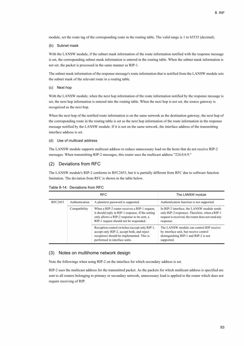
8. RIP
module, set the route tag of the corresponding route in the routing table. The valid range is 1 to 65535 (decimal).
(b) Subnet mask
With the LANSW module, if the subnet mask information of the route information notified with the response message is set, the corresponding subnet mask information is entered in the routing table. When the subnet mask information is not set, the packet is processed in the same manner as RIP-1.
The subnet mask information of the response message's route information that is notified from the LANSW module sets the subnet mask of the relevant route in a routing table.
(c) Next hop
With the LANSW module, when the next hop information of the route information notified by the response message is set, the next hop information is entered into the routing table. When the next hop is not set, the source gateway is recognized as the next hop.
When the next hop of the notified route information is on the same network as the destination gateway, the next hop of the corresponding route in the routing table is set as the next hop information of the route information in the response message notified by the LANSW module. If it is not on the same network, the interface address of the transmitting interface address is set.
(d) Use of multicast address
The LANSW module supports multicast address to reduce unnecessary load on the hosts that do not receive RIP-2 messages. When transmitting RIP-2 messages, this router uses the multicast address "224.0.0.9."
(2) Deviations from RFC
The LANSW module's RIP-2 conforms to RFC2453, but it is partially different from RFC due to software function limitation. The deviation from RFC is shown in the table below.
Table 8-14: Deviations from RFC
(3) Notes on multihome network design
Note the followings when using RIP-2 on the interface for which secondary address is set.
RIP-2 uses the multicast address for the transmitted packet. As the packets for which multicast address is specified are sent to all routers belonging to primary or secondary network, unnecessary load is applied to the router which does not require receiving of RIP.
RFC The LANSW module
RFC2453 Authentication A plaintext password is supported. Authentication function is not supported.
Compatibility When a RIP-2 router receives a RIP-1 request, it should reply in RIP-1 response. If the setting only allows a RIP-2 response to be sent, a RIP-1 request should not be responded.
In RIP-2 interface, the LANSW module sends only RIP-2 responses. Therefore, when a RIP-1 request is received, the router does not send any response.
Reception control switches (accept only RIP-1, accept only RIP-2, accept both, and reject reception) should be implemented. This is performed in interface units.
The LANSW module can control RIP receive by interface unit, but receive control distinguishing RIP-1 and RIP-2 is not supported.
93
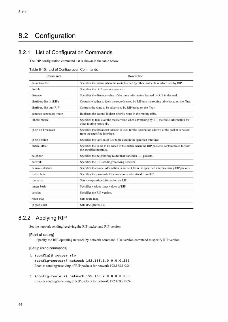
8. RIP
8.2 Configuration
8.2.1 List of Configuration CommandsThe RIP configuration command list is shown in the table below.
Table 8-15: List of Configuration Commands
8.2.2 Applying RIPSet the network sending/receiving the RIP packet and RIP version.
[Point of setting]Specify the RIP-operating network by network command. Use version command to specify RIP version.
[Setup using commands]
1. (config)# router rip
(config-router)# network 192.168.1.0 0.0.0.255
Enables sending/receiving of RIP packets for network 192.168.1.0/24.
2. (config-router)# network 192.168.2.0 0.0.0.255
Enables sending/receiving of RIP packets for network 192.168.2.0/24.
Command Description
default-metric Specifies the metric when the route learned by other protocols is advertised by RIP.
disable Specifies that RIP does not operate.
distance Specifies the distance value of the route information learned by RIP in decimal.
distribute-list in (RIP) Controls whether to fetch the route learned by RIP into the routing table based on the filter.
distribute-list out (RIP) Controls the route to be advertised by RIP based on the filter.
generate-secondary-route Registers the second-highest priority route in the routing table.
inherit-metric Specifies to take over the metric value when advertising by RIP the route information for other routing protocols.
ip rip v2-broadcast Specifies that broadcast address is used for the destination address of the packet to be sent from the specified interface.
ip rip version Specifies the version of RIP to be used in the specified interface.
metric-offset Specifies the value to be added to the metric when the RIP packet is sent/received to/from the specified interface.
neighbor Specifies the neighboring router that transmits RIP packets.
network Specifies the RIP-sending/receiving network.
passive-interface Specifies that route information is not sent from the specified interface using RIP packets.
redistribute Specifies the protocol of the route to be advertised from RIP.
router rip Sets the operation information on RIP.
timers basic Specifies various timer values of RIP.
version Specifies the RIP version.
route-map Sets route-map.
ip prefix-list Sets IPv4 prefix-list.
94

8. RIP
3. (config-router)# version 2
Sets RIP version to RIP-2.
8.2.3 Setting Metric
(1) Setting of metric value when advertising route information other than RIP
Set the metric value when the route learned by other protocols is advertised by RIP.
[Point of setting]When advertising OSPF or BGP4 route by RIP, metric value must be set in configuration. Use default-metric command to set the metric value.
[Setup using commands]
1. (config)# router rip
(config-router)# network 192.168.1.0 0.0.0.255
(config-router)# network 192.168.2.0 0.0.0.255
(config-router)# default-metric 3
Sets 3 as the metric value when the route information learned by other protocols is advertised by RIP.
2. (config-router)# redistribute static
Sets that static route is advertised by RIP.
3. (config-router)# redistribute ospf
Sets that OSPF route is advertised by RIP.
(2) Setting of the value to be added to metric value when sending/receiving packets
Set the value to be added to metric value when sending/receiving RIP packets.
[Point of setting]Use metric-offset command to set the value to be added to metric value of the route sent/received by a specific interface.
[Setup using commands]
1. (config)# router rip
(config-router)# network 192.168.1.0 0.0.0.255
(config-router)# network 192.168.2.0 0.0.0.255
(config-router)# metric-offset 2 vlan 10 out
Adds 2 to metric value of the RIP packet to be sent from interface vlan 10.
2. (config-router)# metric-offset 2 vlan 20 in
Adds 2 to metric value of the RIP packet to be received from interface vlan 20.
8.2.4 Adjusting TimerAdjust RIP periodic advertisement timer value, aging timer value, and the time to be taken until deleted from the routing table.
95

8. RIP
To reduce convergence time when changing the route, set periodic advertisement timer value and aging timer value smaller than the default value. To reduce traffic of periodic advertisement of RIP, set the periodic advertisement timer value greater than the default value.
When RIP's timer value is changed, apply the changed timer value to all routers on the RIP network as well.
[Point of setting]Use timers basic command to change RIP's timer value.
[Setup using commands]
1. (config)# router rip
(config-router)# network 192.168.1.0 0.0.0.255
(config-router)# network 192.168.2.0 0.0.0.255
(config-router)# timers basic 40 200 100
Sets RIP periodic advertisement timer to 40 seconds, aging timer to 200 seconds, and time to be taken until deleted from the routing table to 100 seconds.
8.2.5 Suppressing RIP Packet TransmissionSet suppression of RIP packet sending for each interface.
[Point of setting]Use passive-interface command to suppress RIP sending for each interface.
Figure 8-13: Suppression of RIP Packet Transmission
[Setup using commands]
1. (config)# router rip
(config-router)# network 192.168.1.0 0.0.0.255
(config-router)# network 192.168.2.0 0.0.0.255
(config-router)# passive-interface vlan 20
Suppresses sending of RIP packets to interface vlan 20.
96
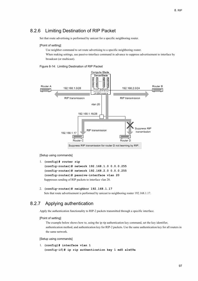
8. RIP
8.2.6 Limiting Destination of RIP PacketSet that route advertising is performed by unicast for a specific neighboring router.
[Point of setting]Use neighbor command to set route advertising to a specific neighboring router.When making settings, use passive-interface command in advance to suppress advertisement to interface by broadcast (or multicast).
Figure 8-14: Limiting Destination of RIP Packet
[Setup using commands]
1. (config)# router rip
(config-router)# network 192.168.1.0 0.0.0.255
(config-router)# network 192.168.2.0 0.0.0.255
(config-router)# passive-interface vlan 20
Suppresses sending of RIP packets to interface vlan 20.
2. (config-router)# neighbor 192.168.1.17
Sets that route advertisement is performed by unicast to neighboring router 192.168.1.17.
8.2.7 Applying authenticationApply the authentication functionality to RIP-2 packets transmitted through a specific interface.
[Point of setting]The example below shows how to, using the ip rip authentication key command, set the key identifier, authentication method, and authentication key for RIP-2 packets. Use the same authentication key for all routers in the same network.
[Setup using commands]
1. (config)# interface vlan 1
(config-if)# ip rip authentication key 1 md5 a1w@9a
97

8. RIP
(config-if)# ip rip version 2
Applies RIP-2 authentication to the interface vlan 1.Sets 1 as the key identifier, cryptographic authentication (Keyed-MD5) as the authentication method, and alw@9a as the authentication key.
98

8. RIP
8.3 Operation
8.3.1 List of Operation CommandsTable below shows the RIP operation command list.
Table 8-16: List of Operation Commands
8.3.2 Checking RIP Operation StatusDisplay RIP protocol information.
Figure 8-15: Execution Result of show ip rip Command
> show ip ripDate 2005/07/14 12:00:00 UTCRIP Flags: <ON>Default Metric: 1, Distance: 120Timers (seconds) Update : 30 Aging : 180 Garbage-Collection : 60
8.3.3 Checking Destination InformationDisplay information on RIP sending destination.
Command Description
show ip interface Displays the IPv4 interface state.
show netstat (netstat) (IPv4) Displays the state and statistics of a network.
show processes cpu unicast Displays the CPU usage of the unicast routing program.
debug protocols unicast Starts operation message display of the event log information that a unicast routing program outputs.
dump protocols unicast Outputs the trace information and control table information collected by a unicast routing program to a file.
erase protocol-dump unicast Deletes the trace information file and control table information file created by a unicast routing program.
no debug protocols unicast Stops operation message display of the event log information that the unicast routing program outputs.
show ip interface ipv4-unicast Displays the IPv4 interface information of the LANSW module recognized by a unicast routing program.
debug ip Displays the packet sent/received by IPv4 routing protocol in real time.
clear ip route Clears and re-registers hardware IPv4 forwarding entries.
show ip entry Displays detailed information on specific IPv4 unicast route.
show ip route Displays the route information held in the routing table.
show ip rip Displays RIP protocol information.
clear counters rip ipv4-unicast Clears RIP protocol information.
99

8. RIP
Figure 8-16: Execution Result of show ip rip target Command
> show ip rip targetDate 2005/07/14 12:00:00 UTCSource Address Destination Flags192.168.1.1 192.168.1.100 <V1 Unicast>192.168.1.1 192.168.1.200 <V1 Unicast>192.168.1.1 192.168.1.255 <V1 Passive>192.168.2.1 192.168.2.255 <V2 Multicast>
8.3.4 Checking Learned Route Information
(1) Checking for each network
Display route information learned by RIP contained in specified network.
Figure 8-17: Execution Result of show ip rip route Command
> show ip rip route 172.0.0.0/8Date 2005/07/14 12:00:00 UTCStatus Codes: * valid, > active Destination Next Hop Interface Metric Tag Timer*> 172.16/16 192.168.1.100 VLAN0010 3 0 4s*> 172.17/16 192.168.2.2 VLAN0020 4 0 10s*> 172.18/16 192.168.2.2 VLAN0020 3 0 10s*> 172.19/16 192.168.1.200 VLAN0010 5 0 17s
(2) Checking for each gateway
Display the route information learned from the specified gateway.
Figure 8-18: Execution Result of show ip rip received-routes Command
> show ip rip received-routes 192.168.2.2Date 2005/07/14 12:00:00 UTCStatus Codes: * valid, > active Neighbor Address: 192.168.2.2 Destination Next Hop Interface Metric Tag Timer*> 172.17/16 192.168.2.2 VLAN0020 4 0 15s*> 172.18/16 192.168.2.2 VLAN0020 3 0 15s*> 192.168.3/24 192.168.2.2 VLAN0020 2 0 15s*> 192.168.5/24 192.168.2.2 VLAN0020 4 0 15s
8.3.5 Checking Advertised Route Information
(1) Checking for each destination
Display the route information sent to the specified target.
Figure 8-19: Execution Result of show ip rip advertised-routes Command (1)
> show ip rip advertised-routes 192.168.2.255Date 2005/07/14 12:00:00 UTCTarget Address: 192.168.2.255Destination Next Hop Interface Metric Tag Age172.16/16 192.168.1.100 VLAN0010 4 0 19s172.19/16 192.168.1.200 VLAN0010 6 0 2s192.168.4/24 192.168.1.200 VLAN0010 3 0 2s192.168.6/24 192.168.1.100 VLAN0010 5 0 19s
(2) Checking for each network
Display all route information sent by RIP contained in specified network for each target.
100

8. RIP
Figure 8-20: Execution Result of show ip rip advertised-routes Command (2)
> show ip rip advertised-routes 172.0.0.0/8Date 2005/07/14 12:00:00 UTCTarget Address: 192.168.1.100Destination Next Hop Interface Metric Tag Age172.17/16 192.168.2.2 VLAN0020 5 0 1s172.18/16 192.168.2.2 VLAN0020 4 0 1s172.19/16 192.168.1.200 VLAN0010 6 0 7sTarget Address: 192.168.1.200Destination Next Hop Interface Metric Tag Age172.16/16 192.168.1.100 VLAN0010 4 0 24s172.17/16 192.168.2.2 VLAN0020 5 0 1s172.18/16 192.168.2.2 VLAN0020 4 0 1sTarget Address: 192.168.2.255Destination Next Hop Interface Metric Tag Age172.16/16 192.168.1.100 VLAN0010 4 0 24s172.19/16 192.168.1.200 VLAN0010 6 0 7s
101

8. RIP
102

9. OSPF
9 OSPF This chapter describes OSPF of the IPv4 routing protocol.
9.1 OSPF Basic Function Overview
9.2 Configuration of OSPF Basic Functions
9.3 Interface Overview
9.4 Configuration of Interface
9.5 Operation of OSPF
103

9. OSPF
9.1 OSPF Basic Function Overview
OSPF (Open Shortest Path First) is a routing protocol based on the topology constituted by the connection state between routers and the shortest path calculation using the Dijkstra algorithm.
9.1.1 Features of OSPFOSPF is usually used to determine the path in one AS. In OSPF, the database of the topology constituted by all connection states in AS exists in each router. Each router calculates the shortest path according to this database. OSPF has the following features as compared with the routing protocol (i.e., RIP) in AS.
• Deletion of route information trafficIn OSPF, the information on the connection state is reported to other routers only when the connection state between routers has changed. In OSPF, therefore, the traffic that the routing protocol occupies further decreases when compared with the routing protocol (i.e., RIP) that periodically reports all path information. In OSPF, only the information on the connection state of a local router is reported to other routers at intervals of 30 minutes.
• Suppression of routing loopAll routers using OSPF maintain database consisting of the same data. Each route selects route based on the common data. Therefore, unlike RIP, a routing loop (the circulation of a relay route) does not occur.
• Route selection by costIn OSPF, when multiple routes to the destination exist, the lowest cost route to the destination is selected. Unlike RIP, the cost in a route can be thus set flexibly. Therefore, the desirable route can be selected irrespective of the number of relay stages.
• Operation of large-scale networkIn OSPF, the route in which cost is more than 65,536 is considered to be unreachable. Therefore, OSPF is suitable for the operation of a larger-scale network in which a route that has many routers to pass through exists, as compared with RIP which considers that the route in which metric is more than 16 is unreachable.
• Variable length subnetUnlike RIP-1, OSPF can handle network divided into subnets because the route information includes subnet mask.
Note on the selection of protocol usedUnlike RIP-1, RIP-2 can also handle network divided into subnets by including the subnet mask information. The use of RIP-2 is recommended if the purpose is only to handle a subnet and if all routers can use RIP-2.
9.1.2 Functions of OSPFThe functions of OSPF are shown in the table below. It is possible with the LANSW module to connect to multiple OSPF networks with one router and individually exchange, calculate, and generate paths in each OSPF network. This is referred to as the OSPF multi-backbone function. Independent OSPF networks are referred to as OSPF domains.
Table 9-1: Functions of OSPF
Function OSPF
Forwarding address of AS external path Y
NSSA Y
Authentication Y
Non-broadcast (NBMA) network Y
Equal cost multipath Y
Virtual link Y
Multi-backbone Y
104

9. OSPF
(Legend) Y: Handled N: Not handled
9.1.3 Route Selection AlgorithmIn OSPF, the SPF (Shortest Path First) algorithm is used as the algorithm of path selection.
Each router running OSPF has a database containing information on all OSPF-operating routers and all connections between routers as well a between routers and networks. Topology is first constituted from this database with the router and network as a vertex and with the connection between routers and a router and network as a side. The SPF algorithm is applied to this topology so as to create the shortest path tree. Each vertex and the path to an address are determined based on the obtained information.
The figure below shows an example of network configuration.
Figure 9-1: Network Configuration Example
The figure below shows the shortest path tree created, with Router 1 as a root. This figure shows OSPF topology and an example of setting costs among vertexes. For the connection between a router and network, the cost can be set only in the connection from a router to a network. For the connection from a network to a router, the cost is "0" at all times.
The cost is the total of transmission cost in each interface through which the path passes. For example, the cost of a path from Router 1 to Network 2 is 6 (Router 1 - Network 1) + 0 (Network 1 - Router 3) + 2 (Router 3 - Network 2) = 8.
Figure 9-2: Shortest Path Tree with Router 1 as Root
In OSPF, the optimum path is selected according to the cost. In certain configurations, when an improper path is
Helper function of graceful restart Y
Restart function of graceful restart N
Stub router Y
Function OSPF
105

9. OSPF
selected, a proper path can be specified by raising the cost of an improper network interface or lowering the cost of a more proper network interface. When the cost is too low, the cost of interfaces in all routers not including this interface must be sometimes raised because this value cannot be set to under "1". Therefore, in a large-scale network, be careful not to set the cost of an interface to an excessively low level so that the cost of an arbitrary interface can be reduced during optimization in future.
9.1.4 Advertisement of LSA
(1) LSA type
In OSPF, the route information is called Link State Advertise (LSA).
The main LSA is divided into the following three types.
(a) Intra-area route information
Notifies the states of routers and networks used in SPF algorithm.
(b) Inter-area route information
Notifies another area's route.
(c) AS external route information
When OSPF router has information of routes other than AS, the router can notifies these routes to all other OSPF routers by using OSPF. Routers that use OSPF and introduce external routes into OSPF are called "AS boundary routers".
(2) AS external route
When route redistribution filter is set in configuration, AS external route is advertised. The source AS boundary router advertises LSA with the following information added.
• MetricThe metric is used by a router learning the routes to select a route on the basis of comparison with other LSAs. Default value of metric is set by default-metric command.
• Metric typeThere are two types, Type 1 and Type 2. In Type 1 and Type 2 routes, the priority level of a route and the calculation method when using metric for route selection differ. Default metric type is Type 2.
• Forwarding address (forwarding destination)The forwarding address can be reached in OSPF that is used as destination. When not reachable by OSPF, set 0.0.0.0.
• TagA tag can be advertised as additional information.
(3) Advertisement of AS external route among domains
Multiple OSPF domains connected by one router each operate as an independent OSPF network. Therefore, if there is no configuration for route redistribution, routes in one OSPF domain are not distributed to the other OSPF domain. When redistribution filter of OSPF route learned by another domain is set in configuration, another domain's route is advertised as AS external route. Default value shown in the table below is applied to the filter attribute.
106

9. OSPF
Table 9-2: Filter Attributes for Redistributing Route of Another Domain
9.1.5 Installation Example of AS External RouteThe figure below shows an example in configuration using a backup line.
Figure 9-3: Example of Introducing AS External Route Using a Backup Line
With OSPF, packets are exchanged regularly to detect neighboring routers. For this reason, if a backup line is used as part of OSPF topology, the backup line constantly stays active, because it is continually used for packet exchanged. To keep the backup line inactive while communication is not required on this line, the following settings must be made.
On this router, run OSPF on the primary line. On the backup line, set a static route for Network A. In addition, set the distance value of static route greater than the distance value of OSPF intra-area route (priority is low). This enables AS internal route learned by OSPF to be selected as the route to Network A. In case of primary line failure, AS internal route to the corresponding the LANSW module A is deleted and the static route is re-selected, but route information to Network A no longer remains in System C. To advertise the LANSW module A's information on the static route to Network A as an AS external route to System C, it is necessary to set a route redistribution configuration on the LANSW module A. As a result, the effective route information to Network A can be installed in OSPF without exchanging Hello packets on the backup line even when the primary line fails.
9.1.6 Route Selection CriteriaOSPF performs SPF calculation each time LSA is updated by generation or learning of LSA. In SPF calculation, the route is selected based on SPF algorithm. When reachability to the destination is extinguished, the route is deleted.
In the area border router, the route selection is performed individually in all areas to which a router belongs based on SPF algorithm.
The route selection priority in OSPF is shown in the table below. The priority cannot be changed.
Attribute Default Value
AS External Route Intra-area and Inter-area Routes
Metric value Value set by default-metric command. If default-metric setting is omitted, 20.
Value set by default-metric command. If default-metric setting is omitted, 20.
Metric type AS external route or NSSA route Type 2
Tag value Inherits the tag value of the route. 0
107
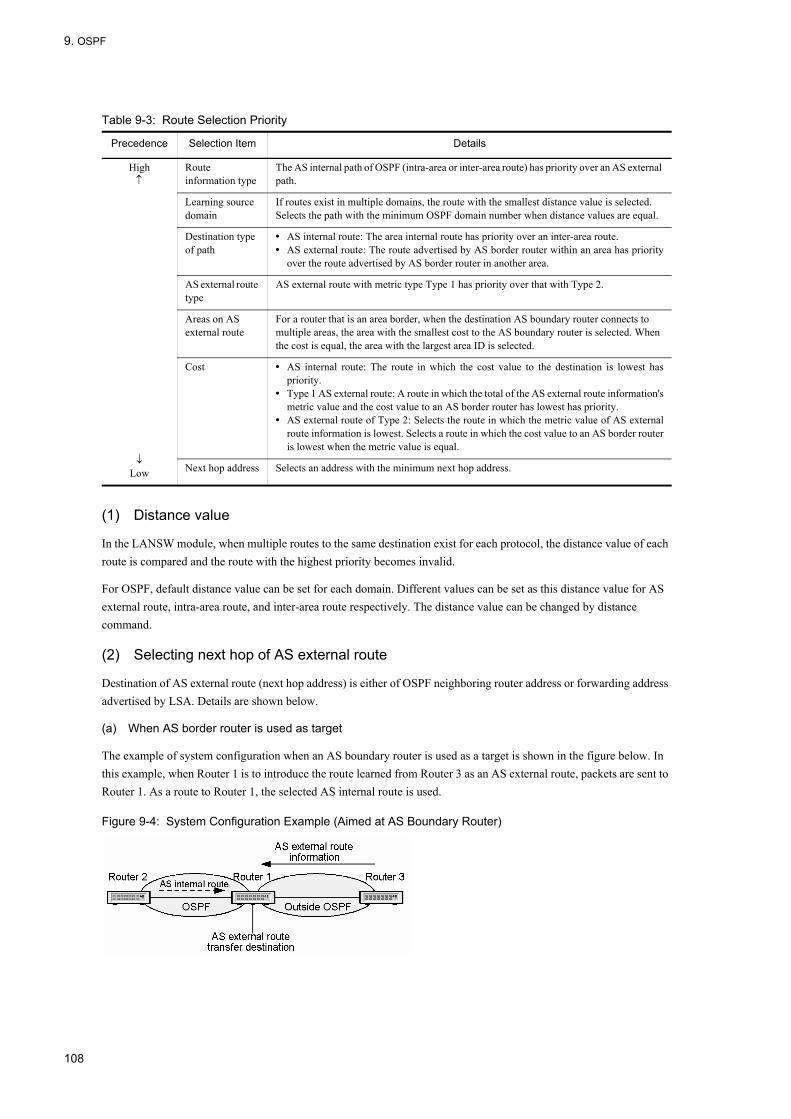
9. OSPF
Table 9-3: Route Selection Priority
(1) Distance value
In the LANSW module, when multiple routes to the same destination exist for each protocol, the distance value of each route is compared and the route with the highest priority becomes invalid.
For OSPF, default distance value can be set for each domain. Different values can be set as this distance value for AS external route, intra-area route, and inter-area route respectively. The distance value can be changed by distance command.
(2) Selecting next hop of AS external route
Destination of AS external route (next hop address) is either of OSPF neighboring router address or forwarding address advertised by LSA. Details are shown below.
(a) When AS border router is used as target
The example of system configuration when an AS boundary router is used as a target is shown in the figure below. In this example, when Router 1 is to introduce the route learned from Router 3 as an AS external route, packets are sent to Router 1. As a route to Router 1, the selected AS internal route is used.
Figure 9-4: System Configuration Example (Aimed at AS Boundary Router)
Precedence Selection Item Details
High↑
↓Low
Route information type
The AS internal path of OSPF (intra-area or inter-area route) has priority over an AS external path.
Learning source domain
If routes exist in multiple domains, the route with the smallest distance value is selected. Selects the path with the minimum OSPF domain number when distance values are equal.
Destination type of path
• AS internal route: The area internal route has priority over an inter-area route.• AS external route: The route advertised by AS border router within an area has priority
over the route advertised by AS border router in another area.
AS external route type
AS external route with metric type Type 1 has priority over that with Type 2.
Areas on AS external route
For a router that is an area border, when the destination AS boundary router connects to multiple areas, the area with the smallest cost to the AS boundary router is selected. When the cost is equal, the area with the largest area ID is selected.
Cost • AS internal route: The route in which the cost value to the destination is lowest haspriority.
• Type 1 AS external route: A route in which the total of the AS external route information'smetric value and the cost value to an AS border router has lowest has priority.
• AS external route of Type 2: Selects the route in which the metric value of AS externalroute information is lowest. Selects a route in which the cost value to an AS border routeris lowest when the metric value is equal.
Next hop address Selects an address with the minimum next hop address.
108
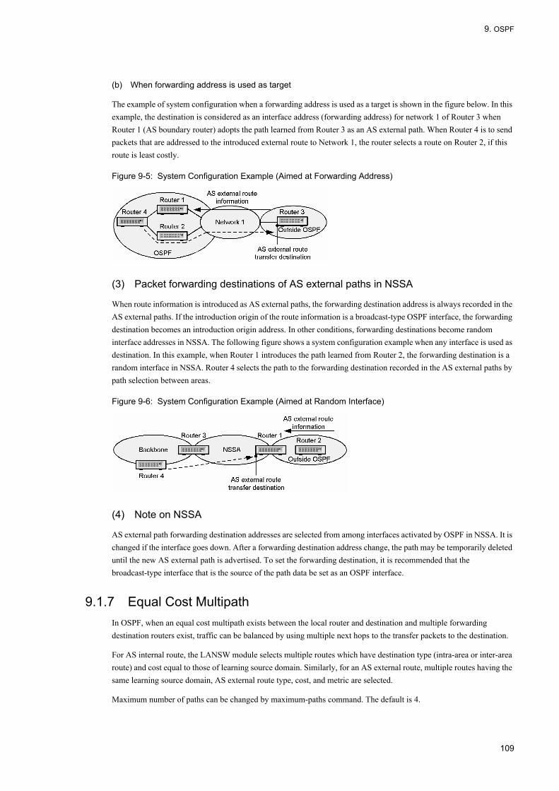
9. OSPF
(b) When forwarding address is used as target
The example of system configuration when a forwarding address is used as a target is shown in the figure below. In this example, the destination is considered as an interface address (forwarding address) for network 1 of Router 3 when Router 1 (AS boundary router) adopts the path learned from Router 3 as an AS external path. When Router 4 is to send packets that are addressed to the introduced external route to Network 1, the router selects a route on Router 2, if this route is least costly.
Figure 9-5: System Configuration Example (Aimed at Forwarding Address)
(3) Packet forwarding destinations of AS external paths in NSSA
When route information is introduced as AS external paths, the forwarding destination address is always recorded in the AS external paths. If the introduction origin of the route information is a broadcast-type OSPF interface, the forwarding destination becomes an introduction origin address. In other conditions, forwarding destinations become random interface addresses in NSSA. The following figure shows a system configuration example when any interface is used as destination. In this example, when Router 1 introduces the path learned from Router 2, the forwarding destination is a random interface in NSSA. Router 4 selects the path to the forwarding destination recorded in the AS external paths by path selection between areas.
Figure 9-6: System Configuration Example (Aimed at Random Interface)
(4) Note on NSSA
AS external path forwarding destination addresses are selected from among interfaces activated by OSPF in NSSA. It is changed if the interface goes down. After a forwarding destination address change, the path may be temporarily deleted until the new AS external path is advertised. To set the forwarding destination, it is recommended that the broadcast-type interface that is the source of the path data be set as an OSPF interface.
9.1.7 Equal Cost MultipathIn OSPF, when an equal cost multipath exists between the local router and destination and multiple forwarding destination routers exist, traffic can be balanced by using multiple next hops to the transfer packets to the destination.
For AS internal route, the LANSW module selects multiple routes which have destination type (intra-area or inter-area route) and cost equal to those of learning source domain. Similarly, for an AS external route, multiple routes having the same learning source domain, AS external route type, cost, and metric are selected.
Maximum number of paths can be changed by maximum-paths command. The default is 4.
109

9. OSPF
9.1.8 Notes
(1) Notes on router ID and network address
In OSPF, router ID is used for identification of a router when constructing the topology of a network.
The topology cannot be accurately constructed when the following violation exists during design of a network
• When the same router ID is set for multiple routers in one domain• When the same network address is assigned to different networks
If the violation above exists, a path cannot be accurately selected because it is based on inaccurate topology. The method below is recommended as the way to determine a router ID.
How to determine router IDIn determining the router IDs of each router, select one of the IP addresses assigned to the interface in which OSPF in the corresponding router operates and use it as a router ID. The router ID is basically a 32 bit value, but the above method can prevent router IDs from overlapping due to an error during the design of an OSPF network.When one router is connected to multiple OSPF domains, it is no problem if the same router ID is used in all domains.
(2) Notes on route redistribution filter and learning filter
For OSPF, all LSAs learned from the neighboring router are advertised to other neighboring routers. Advertisement of route learned by OSPF in the same domain cannot be suppressed with redistribution filter. Also, when aggregating OSPF route by using the aggregate function, advertisement of LSA in the same domain cannot be suppressed even if suppression of aggregate source route is set.
The distribute-list in command can suppress learning of AS external route satisfying the filter conditions. However, learning and advertisement of LSA cannot be suppressed. Thus, the routes not learned are also advertised by OSPF.
(3) Notes on using multi-backbone function
(a) Note on using multi-backbone
If the network is divided into multiple OSPF domains and operated, OSPF features such as routing group constraint and path selection based on cost are lost due to the selection or distribution of paths between OSPF domains. When developing a new network, for example, it is recommended that it be developed as a single OSPF network if there is no need to divide it into multiple OSPF domains.
(b) Notes on setting multiple domains
Advertise it as an OSPF AS external path when a system address must be advertised for multiple OSPF domains. It is impossible to set one interface for multiple OSPF domains simultaneously in configuration.
Up to four OSPF domains can be set.
110
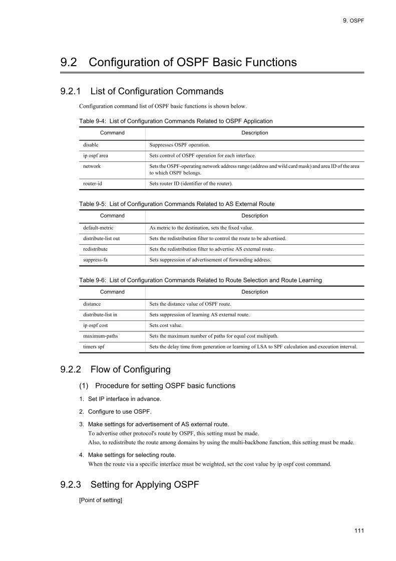
9. OSPF
9.2 Configuration of OSPF Basic Functions
9.2.1 List of Configuration CommandsConfiguration command list of OSPF basic functions is shown below.
Table 9-4: List of Configuration Commands Related to OSPF Application
Table 9-5: List of Configuration Commands Related to AS External Route
Table 9-6: List of Configuration Commands Related to Route Selection and Route Learning
9.2.2 Flow of Configuring
(1) Procedure for setting OSPF basic functions
1. Set IP interface in advance.
2. Configure to use OSPF.
3. Make settings for advertisement of AS external route.To advertise other protocol's route by OSPF, this setting must be made.Also, to redistribute the route among domains by using the multi-backbone function, this setting must be made.
4. Make settings for selecting route.When the route via a specific interface must be weighted, set the cost value by ip ospf cost command.
9.2.3 Setting for Applying OSPF[Point of setting]
Command Description
disable Suppresses OSPF operation.
ip ospf area Sets control of OSPF operation for each interface.
network Sets the OSPF-operating network address range (address and wild card mask) and area ID of the area to which OSPF belongs.
router-id Sets router ID (identifier of the router).
Command Description
default-metric As metric to the destination, sets the fixed value.
distribute-list out Sets the redistribution filter to control the route to be advertised.
redistribute Sets the redistribution filter to advertise AS external route.
suppress-fa Sets suppression of advertisement of forwarding address.
Command Description
distance Sets the distance value of OSPF route.
distribute-list in Sets suppression of learning AS external route.
ip ospf cost Sets cost value.
maximum-paths Sets the maximum number of paths for equal cost multipath.
timers spf Sets the delay time from generation or learning of LSA to SPF calculation and execution interval.
111

9. OSPF
• When router ID is omitted, loopback address is used as router ID. When loopback address is not set, OSPF does not operate.
• Exchange LSA with neighboring router on the interface which has the interface address matching the range specified by network command.
• When area is not divided, area ID must be set to the same value for all OSPF routers.
[Setup using commands]
1. (config)# router ospf 1
Moves to ospf mode. Sets the domain number to 1.
2. (config-router)# router-id 100.1.1.1
Uses 100.1.1.1 as router ID.
3. (config-router)# network 10.0.0.0 0.255.255.255 area 0
Specifies that the interface within the range of network 10.0.0.0/8 belongs to area 0.
9.2.4 Setting AS External Route Advertisement[Point of setting]
• redistribute command can set the information to be added to redistributed route (metric value, tag, and metric type). If metric value is omitted in redistribute command, the value set in default-metric command becomes invalid.
• For the route learned by OSPF, redistribution in the same domain cannot be controlled.• If suppress-fa command is specified, forwarding address is always 0.0.0.0.
[Setup using commands]
1. (config)# router ospf 1
Moves to ospf mode.
2. (config-router)# default-metric 10
Sets the default metric to 10.
3. (config-router)# redistribute static
Advertises the static route with above default metric value.
9.2.5 Setting Route Selection[Point of setting]
Use ip ospf cost command to set cost for each interface.If 1 is set in maximum-paths command, equal cost multipath is not established even though the cost values of the routes are equal.
[Setup using commands]An example of setting when using single-path route is shown below.
1. (config)# router ospf 1
(config-router)# maximum-paths 1
Sets the maximum number of OSPF paths to 1.
112

9. OSPF
2. (config-router)# network 10.0.0.0 0.255.255.255 area 0
(config-router)# exit
Specifies that the interface within the range of network 10.0.0.0/8 belongs to area 0.
3. (config)# interface vlan 1
(config-if)# ip ospf cost 10
(config-if)# exit
Sets the cost to 10.
4. (config)# interface vlan 2
(config-if)# ip ospf cost 2
Sets the cost to 2. The route via VLAN2 takes priority by making VLAN2 cost value smaller than VLAN1 cost value.
9.2.6 Setting Multipath[Point of setting]
By adjusting the cost value, equal cost multipath to the destination can be established regardless of the number of routers through which the route passes.
Figure 9-7: Configuration of Multipath
[Setup using commands]Establish equal cost multipath in the LANSW module.
1. (config)# router ospf 1
(config-router)# network 10.0.0.0 0.255.255.255 area 0
(config-router)# exit
Specifies that the interface within the range of network 10.0.0.0/8 belongs to area 0.
2. (config)# interface vlan 1
(config-if)# ip ospf cost 2
Sets VLAN1 cost value to 2, for making the cost equal to the route via VLAN2.
113

9. OSPF
9.3 Interface Overview
9.3.1 OSPF Interface TypeFor OSPF, the interface connecting routers are classified into 3 types for the reason of sending/receiving OSPF packets.
• BroadcastOn the broadcast type network, multiple neighboring routers on the interface are uniformly managed by using multicast.
• non-broadcast (NBMA)On the broadcast type network, multiple neighboring routers are uniformly managed without using broadcast or multicast.
• Point-to-PointOnly one single neighboring router is managed. On the virtual link, operates as Point-to-Point interface.
(1) Multihome network
The LANSW module allows OSPF to operate on secondary address set for the interface. Note the followings when using OSPF on multiple IP networks among multihome-connected routers in such configuration.
• For the non-NBMA interface, routing packets specified by multicast address are sent to all multihome-connected routers, causing unnecessary load to be applied to routers or networks. To prevent increase in traffic unnecessary for the network, use NBMA interface.
(2) Notes on setting the interface that uses OSPF
OSPF may transmit a packet of a length equal to MTU (the Maximum Transfer Unit) set in an interface. If a packet is longer than MRU (the Maximum Reception Unit: usually equal to MTU) set in an interface on the reception side, mutual communication between routers as an ordinary traffic may become impossible. For this reason, when setting OSPF, confirm every interface of all networks and of all routers connected to a networks that MTU is set to below MRU.
9.3.2 Connection with Neighboring Router
(1) Hello packet
The router in which OSPF operates transmits Hello packets for each interface so as to detect the connection performance between routers. It is recognized that OSPF operates between routers by receiving Hello packets from other routers.
(2) Conditions for connection with neighboring router
For each network directly connecting routers, parameter items of the interface shown below must match among all connected routers. Between routers in which the following do not coincide, the routers are considered to be not connected in OSPF.
(a) Interface address
The interfaces of all routers connected to the same network must have the same mask as an IP network address.
(b) Authentication method and authentication key
In OSPF, authentication can be used to verify whether the route information from the connected router is proper and it is surely sent from that router. The authentication method and key set to this network in the interfaces of all routers
114

9. OSPF
connected to the same network must match when using authentication.
(c) Area ID
For the direct connection between routers, the area set in the interface of both routers must coincide.
(d) Hello Interval and Dead Interval
Hello Interval is the transmission interval of the Hello packet. Dead Interval is the time required to judge that the connection with the router was disconnected because the Hello packet from a router cannot be received. The two values set in the interface of the directly connected router must coincide to judge detection and disconnection properly.
(e) Setting of area
The information reported to an area differs, in a stub area or NSSSA and an area that is not stub or NSSA. So as to judge that OSPF directly connects two routers, the stub settings of the areas to which an interface belongs must match.
9.3.3 Broadcast-type Network and Designated RouterIn a broadcast-type network, a designated router and backup designated router are selected to manage the connection information between the vertex (i.e., network) in topology and the routers directly connected to the network. A backup designated router is selected as the designated router so as to rapidly shift the management router of connection information in a network when a failure occurs in the designated router.
(1) Selecting designated router and backup designated router
Each router advertises the priority for selecting the designated router on the interface by using Hello packet.
When neither designated router nor backup designated router exists on the interface, a router with the highest priority is selected as the designated router. When the designated router exists but the backup designated router does not exist, a router with highest priority, not including the designated router, is selected as the backup designated router. When both routers exist, the selection is not changed even if a router with higher priority appears newly.
When the priority of an interface in a certain router is set to "0", this router is neither selected as the designated router nor backup designated router in the area where an interface is connected.
The priority level of the interface connected to this network of either router must be set to "1" or more when multiple routers exist in a broadcast-type network and when this network is used for transfer of traffic.
9.3.4 Transmission of LSAWith OSPF, the neighboring routers transmit to each other LSAs which others do not have. A router that has generated or received a new LSA transmits the LSA to all neighbors. The LANSW module and neighbors therefore can hold the same database. The relationship that database is synchronized by sending/receiving of LSA is called neighbor adjacency.
LSAs of the LANSW module are sent to all neighboring routers according to LSA synchronization procedures. A neighbor in turn transmits the LSAs of the LANSW module to all its neighbors. Further, a neighbor of the neighbor transmits the LSAs to all its neighbors. In this way, the LSAs of the LANSW module are distributed to all the routers in the appropriate area.
(1) Age of LSA
Age is the time elapsed from generation of LSA. LSA is held until Age becomes 3600 seconds or deleted by the router which generated it. The value obtained by adding the delay time (value set in ip ospf transmit-delay command) to Age of LSA is used as Age field value of LSA to be transmitted.
115

9. OSPF
9.3.5 Passive InterfaceThe interface which has no OSPF neighboring router can be set as passive interface. When OSPF is applied to loopback interface, it is used as passive interface.
Passive interface does not send/receive OSPF packets.
Direct-connection route of passive interface is advertised as inter-area or inter-area route.
116

9. OSPF
9.4 Configuration of Interface
9.4.1 List of Configuration CommandsList of configuration commands related to OSPF packets and NBMA settings is shown in table below.
Table 9-7: List of Configuration Commands
Table below shows a list of configuration commands related to OSPF operation.
OSPF can receive error packets and send trap of OSPF state change.
Table 9-8: List of Configuration Commands (Commands Related to OSPF Operation)
9.4.2 Flow of Configuring
(1) Procedure for setting NBMA interface
1. Set IP interface in advance.
2. Set the basic functions.Make settings for applying OSPF.For details, see "9.2 Configuration of OSPF Basic Functions".
3. Make interface-related settings.Set the interface type to NBMA by ip ospf network command.Change parameters such as transmission interval of Hello packets, as required.
4. Set the neighboring router by neighbor command.
(2) Procedure for setting broadcast interface
1. Set IP interface in advance.
2. Set the basic functions.
Command Description
ip ospf dead-interval Sets the time during which neighbor adjacency is maintained when Hello packets cannot be received from the neighboring router.
ip ospf hello-interval Sets the transmission interval in seconds for the Hello packet.
ip ospf network Sets the interface type (broadcast or NBMA).
ip ospf priority Sets the priority for selecting designated router.
ip ospf retransmit-interval Sets retransmission interval of LSA.
ip ospf transmit-delay Sets the delay time in seconds needed to transmit the OSPF packet.
neighbor (ospf mode) Displays the neighboring router address.
passive-interface (ospf mode) Sets passive interface.
Command Description
interface loopback Sets loopback interface (which can be used OSPF passive interface).
ip mtu Specifies IP MTU length for the interface.
system mtu Sets the system's MTU.
snmp-server host Sets the network management system to which trap is sent.
117

9. OSPF
Make settings for applying OSPF.For details, see "9.2 Configuration of OSPF Basic Functions".
3. Make interface-related settings.Parameters such as transmission interval of Hello packets can be changed.
9.4.3 Setting Neighboring Router for NBMA[Point of setting]
neighbor command is valid for NBMA interface only.Specify whether neighboring router is qualified as a designated router by priority parameter of neighbor command. Priority 0 indicates that a router is not qualified as the designated router. Be sure to specify priority when the neighboring router is qualified as a designated router.
[Setup using commands]
1. (config)# interface vlan 1
(config-if)# ip ospf 1 area 0
Applies OSPF.
2. (config-if)# ip ospf network non-broadcast
(config-if)# exit
Sets interface type to NBMA.
3. (config)# router ospf 1
(config-router)# neighbor 192.168.1.1 priority 2
(config-router)# neighbor 192.168.1.2 priority 2
Sets the interface address of neighboring router in domain. Also, sets priority of the neighboring router to 2.
9.4.4 Setting Interface Parameter ChangeOSPF-applied interface transmits Hello packets according to the default value of configuration. Operation can be changed by setting priority or passive-interface command.
(1) Priority to be selected as designated router
The load on the designated router increases in a network that has a large number of connected routers. Therefore, set the priority so that this router does not become a multiple network-specified router when multiple connected routers exist in such a network.
[Point of setting]The greater the value of priority, the higher the priority.
[Setup using commands]
1. (config)# interface vlan 1
(config-if)# ip ospf 1 area 0
(config-if)# ip ospf priority 10
Sets priority to 10.
118

9. OSPF
(2) Passive interface
[Point of setting]Use passive-interface command. When ip ospf cost command is specified, direct-connection route is advertised with the specified cost value.
[Setup using commands]
1. (config)# interface vlan 2
(config-if)# ip ospf 1 area 0
(config-if)# ip ospf cost 10
(config-if)# exit
Applies OSPF.
2. (config)# router ospf 1
(config-router)# passive-interface vlan 2
Sets VLAN2 as passive interface.
119

9. OSPF
9.5 Operation of OSPF
9.5.1 List of Operation CommandsTable below shows the OSPF operation command list.
Table 9-9: List of Operation Commands
Table 9-10: List of Operation Commands Common throughout the LANSW Module
9.5.2 Checking DomainWhen OSPF is operating, use operation command show ip ospf to check setting contents such as router ID or distance value.
Command Description
show ip ospf Displays domain, neighboring router information, interface information, and LSA.
show ip route Displays contents registered in the routing table.
show ip interface ipv4-unicast Displays the IPv4 interface information of the LANSW module recognized by a unicast routing program.
show processes cpu unicast Displays the CPU usage of the unicast routing program.
debug protocols unicast Starts operation message display of the event log information that a unicast routing program outputs.
dump protocols unicast Outputs the trace information and control table information collected by a unicast routing program to a file.
erase protocol-dump unicast Deletes the trace information file and control table information file created by a unicast routing program.
no debug protocols unicast Stops operation message display of the event log information that the unicast routing program outputs.
restart unicast Restarts the unicast routing program.
debug ip Displays the packet sent/received by IPv4 routing protocol in real time.
clear ip ospf Clears OSPF protocol information.
clear ip route Clears and re-registers hardware IPv4 forwarding entries.
show ip entry Displays detailed information on specific IPv4 unicast route.
Command Description
show system Displays the operation state.
ping Sends the test packet to the System with specified IPv4 address, and determines whether communication is possible.
show ip-dual interface Displays the IPv4 and IPv6 interface state.
show ip interface Displays the IPv4 interface state.
traceroute Displays the route through which IPv4 datagram is passed to the destination host.
120
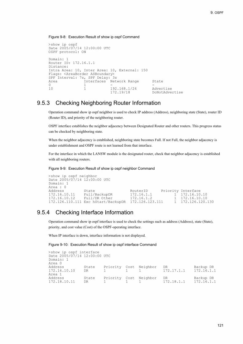
9. OSPF
Figure 9-8: Execution Result of show ip ospf Command
>show ip ospfDate 2005/07/14 12:00:00 UTCOSPF protocol: ON Domain: 1Router ID: 172.16.1.1Distance:Intra Area: 10, Inter Area: 10, External: 150Flags: <AreaBorder ASBoundary>SPF Interval: 7s, SPF Delay: 3sArea Interfaces Network Range State0 1 - -10 1 192.168.1/24 Advertise 172.19/18 DoNotAdvertise
9.5.3 Checking Neighboring Router InformationOperation command show ip ospf neighbor is used to check IP address (Address), neighboring state (State), router ID (Router ID), and priority of the neighboring router.
OSPF interface establishes the neighbor adjacency between Designated Router and other routers. This progress status can be checked by neighboring state.
When the neighbor adjacency is established, neighboring state becomes Full. If not Full, the neighbor adjacency is under establishment and OSPF route is not learned from that interface.
For the interface in which the LANSW module is the designated router, check that neighbor adjacency is established with all neighboring routers.
Figure 9-9: Execution Result of show ip ospf neighbor Command
>show ip ospf neighborDate 2005/07/14 12:00:00 UTCDomain: 1Area : 0Address State RouterID Priority Interface172.16.10.11 Full/BackupDR 172.16.1.1 1 172.16.10.10172.16.10.12 Full/DR Other 172.16.1.2 1 172.16.10.10172.126.110.111 Exc hStart/BackupDR 172.126.123.111 1 172.126.120.130
9.5.4 Checking Interface InformationOperation command show ip ospf interface is used to check the settings such as address (Address), state (State), priority, and cost value (Cost) of the OSPF-operating interface.
When IP interface is down, interface information is not displayed.
Figure 9-10: Execution Result of show ip ospf interface Command
>show ip ospf interfaceDate 2005/07/14 12:00:00 UTCDomain: 1Area 0Address State Priority Cost Neighbor DR Backup DR172.16.10.10 DR 1 1 1 172.17.1.1 172.16.1.1Area 1Address State Priority Cost Neighbor DR Backup DR172.18.10.11 DR 1 1 1 172.18.1.1 172.16.1.1
121
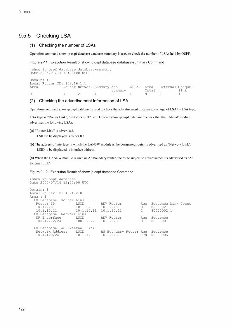
9. OSPF
9.5.5 Checking LSA
(1) Checking the number of LSAs
Operation command show ip ospf database database-summary is used to check the number of LSAs held by OSPF.
Figure 9-11: Execution Result of show ip ospf database database-summary Command
>show ip ospf database database-summaryDate 2005/07/14 12:00:00 UTC Domain: 1Local Router ID: 172.16.1.1Area Router Network Summary Asb- NSSA Area External Opaque- summary Total link0 4 2 1 2 0 9 2 1
(2) Checking the advertisement information of LSA
Operation command show ip ospf database is used to check the advertisement information or Age of LSA by LSA type.
LSA type is "Router Link", "Network Link", etc. Execute show ip ospf database to check that the LANSW module advertises the following LSAs:
(a) "Router Link" is advertised.LSID to be displayed is router ID.
(b) The address of interface in which the LANSW module is the designated router is advertised as "Network Link".LSID to be displayed is interface address.
(c) When the LANSW module is used as AS boundary router, the route subject to advertisement is advertised as "AS External Link".
Figure 9-12: Execution Result of show ip ospf database Command
>show ip ospf databaseDate 2005/07/14 12:00:00 UTC Domain: 1Local Router ID: 10.1.2.8Area : 1 LS Database: Router Link Router ID LSID ADV Router Age Sequence Link Count 10.1.2.8 10.1.2.8 10.1.2.8 3 80000021 1 10.1.10.11 10.1.10.11 10.1.10.11 2 80000002 1 LS Database: Network Link DR Interface LSID ADV Router Age Sequence 100.1.2.2/24 100.1.2.2 10.1.2.8 3 80000001 LS Database: AS External Link Network Address LSID AS Boundary Router Age Sequence 10.1.1.0/24 10.1.1.0 10.1.2.8 778 80000005
122
10. OSPF Extended Function
10OSPF Extended Function This chapter describes extended OSPF functions.
10.1 Area and Area Partitioning Function Overview
10.2 Configuration of Area
10.3 Neighboring Router Authentication Overview
10.4 Configuration of Neighboring Router Authentication
10.5 Graceful Restart Overview
10.6 Configuration of Graceful Restart
10.7 Stub Router Overview
10.8 Configuration of Stub Router
10.9 Operation of OSPF Extended Function
123

10. OSPF Extended Function
10.1 Area and Area Partitioning Function Overview
10.1.1 Area BorderIn order to reduce the traffic required for routing and the time required by the algorithm used for route selection, OSPF can divide AS into multiple areas. An example of OSPF network topology using area partitioning is shown in the figure below.
Figure 10-1: Example of OSPF Network Topology Using Area Partitioning
Like Router 2 or Router 5, the router belonging to multiple areas is called an area border router.
The information on the connection state in an area is not notified to other areas. A router contains no information on the connection state in the area that is not connected.
(1) Backbone
The area where the area ID is 0 is called the backbone. The backbone plays a special part when AS is divided into multiple areas. When dividing AS into multiple areas, one of them must be set as a backbone area. However, do not configure so that two or more backbones exist in one AS. In such configuration, information is dispersed into each backbone. Therefore, an unreachable route may be generated or an optimum route may not be selected.
The area border router also reports the summarized path information of backbone and that of other areas flowing through the backbone to the routers in the connected areas other than backbone.
(2) Note on area partitioning
Area partitioning lessens the load on a router or path information traffic, but the OSPF algorithm is more complicated. Especially, it becomes difficult to perform a proper operation when trouble occurs. Area partitioning should not be performed if there is no problem with the router or network load.
(3) Notes on area border router• An area border router operates the SPF algorithm proportionally to the number of areas to which it belongs. The area
border router has a function that summarizes the topology information in a certain area and reports it to other areas. Therefore, the area border router load increases when the number of areas to which the area border router belongs increases. It is thus recommended to construct a network so that the area border router does not belong to excessively many areas.
• When only one area border router exists in a certain area, the connectivity with other areas is lost by disconnecting the area border router from a backbone if a failure occurs in this area border router. Multiple area border routers should be arranged in the area which the server that offers an important function or the AS border router that has an
124

10. OSPF Extended Function
important connection exists, and a network should be constructed so that a satisfactory bypass path exists for the arrangement of the area border routers.
10.1.2 Route Control with Area PartitionedAn area border router summarizes the route information of all areas (not including a backbone) to which it belongs and reports it to all routers belonging to a backbone. Summary of the backbone route information and the route information on other areas summarized across the backbone are notified to a router in an area connected other than the backbone.
When a router determines the route for an address according to the summarized route information, the route for this address passes through an area border router that is the notification source of the summarized route information. Therefore, the route connected between different areas always passes through the backbone.
When advertising the path information of an area to other areas, the area border router summarizes the topology information made of connection states and cost between routers and networks into the costs from the area border router to the routers or networks.
(1) Route aggregation by area border router
Aggregation and suppression of path, and summarization of path into outside of area is shown in the table below.
Table 10-1: Route Aggregation, Suppression, and Summary for External Area
In summarizing the topology information in the area in an area border router, the path information contained in the address range can be aggregated into one by setting the range of addresses in configuration. The address range is specified using a masked addresses with area range command. Also, parameter for suppressing advertisement can be specified.
All networks contained in the range are aggregated into the path information with the masked address set as destination if even one network contained in the range of the masked address set in configuration exists in an area. The networks are then reported to other areas. Each network contained in the range is not reported from this area border router to other areas. At that time, the highest cost in the network contained in the range is used for the cost of the aggregated path information.
When advertisement is suppressed, each network in the range is not reported to other areas, and the path aggregated into the masked address is not reported to other areas either. As a result, the path to the address contained in the specified range seems to be nonexistent when viewing from other areas through the area border router.
Network Address in Area Setting of Aggregation and Suppression
Summary Reported Outside of Area
10.0.1.0/2410.0.2.0/2510.0.2.128/2510.0.3.0/24
None 10.0.1.0/2410.0.2.0/2510.0.2.128/2510.0.3.0/24
10.0.1.0/2410.0.2.0/2510.0.2.128/2510.0.3.0/24
10.0.0.0/2310.0.2.0/24
10.0.0.0/2310.0.2.0/2410.0.3.0/24
10.0.1.0/2410.0.2.0/2510.0.2.128/2510.0.3.0/24192.168.3.0/26192.168.3.64/26192.168.3.128/26
10.0.0.0/8 (Suppressed)192.168.3.0/24
192.168.3.0/24
125

10. OSPF Extended Function
10.1.3 Stub AreaThe area in which the AS boundary router does not exist can be set as the stub area, not as the backbone. The area stub configuration command is used for this setting.
The AS excluded route is not advertised in the area set as the stub area. With this, the route information is decreased within the stub area and the load of router information replacement and of route selection can be reduced. The area border router introduces the default route in the stub area, in stead of the AS excluded route.
If the area stub command specifies the no-summary parameter, the advertisement of the route outside the area (inter-area route information) is suppressed (only the default route remains as the route to the outside of the area).
10.1.4 NSSAThe area not used as the backbone can be set as NSSA. The area nssa configuration command is used for this setting.
Like the stub area, the AS excluded route that was learned in another area is not advertised in NSSA.
If the advertisement route filter (redistribute configuration command) is set and the area nssa command specifies the no-redistribution parameter, the area border router does not introduce the AS excluded route in NSSA. With this, route information is decreased within NSSA and the load of the router information replacement and of the route selection can be reduced.
If the area nssa command specifies the no-summary parameter, the area border router suppresses the advertisement of the route outside the area (inter-area route information) and introduces the default route as the alternative one. This default route is advertised in NSSA as the inter-area route information (Type3LSA).
(1) AS Excluded Route Advertisement
The AS boundary router in NSSA generates the AS excluded route as Type7 (NSSA external) LSA. This LSA is advertised only in the router in the same area.
If the area nssa command specifies the "default-information-originate" parameter, the area border router introduces the default route in NSSA using Type7LSA. If two or more routers for advertising the default route using Type7LSA exist in NSSA, the route having the higher priority is selected as the AS excluded route.
The area border router converts the AS excluded route it learned in NSSA to Type5LSA and advertises Type5LSA in the area not set as NSSA. In this case, the tag and forwarding address are taken over from Type7LSA for advertisement.
If the "area nssa translate type7 suppress-fa" configuration command is specified in NSSA, or the AS excluded route introduction source, the AS excluded route is converted to Type5LSA and then 0.0.0.0 is always set as the forwarding address.
The following figure shows the route replacement between NSSA and the backbone:
126

10. OSPF Extended Function
Figure 10-2: Route Replacement between NSSA and Backbone
(2) Restrictions
This device conforms to RFC3101The OSPF Not-So-Stubby Area (NSSA) Option). However, it does not support the functions listed below because of the software function restrictions:
• Type-7 Address Ranges• Type-7 Translator Election
For this reason, this device always advertises the AS excluded route it learned from NSSA, in the area not set as NSSA.
10.1.5 Virtual LinkWith OSPF, a route between two area boarder routes in an area, that is not set as a stub area, NSSA, or backbone area, can be virtualized as a point-to-point line to be used as a backbone interface. This virtual line is called a virtual link. The area in which the actual path of a virtual link exists is called the transit area of a virtual link.
The ways to use a virtual link is described below.
• Virtual connection of area not physically connected to backbone• Coupling of multiple backbones• Reserving path for the disconnection caused by backbone failure
(a) Virtual connection of area not physically connected to backbone
In the figure below, Area 2 is not connected to the backbone. In this case, Router 2 becomes an area border router connected to the backbone when a virtual link is set between Router 1 and Router 2 with area 1 used as a transit area. At that time, area 2 is considered to be connected to the backbone.
Figure 10-3: Connection of Areas to Backbone
(b) Coupling of multiple backbones
In the figure below, two backbone areas exist in AS. In this state, a failure in which the route cannot be reached due to the disruption of a backbone may occur. In this case, the backbone is linked when a virtual link that has area 1 as a transit area is set between routers 1 and 2. As a result, the failure can be avoided.
127

10. OSPF Extended Function
Figure 10-4: Connection between Backbones
(c) Reserving path for the disconnection caused by backbone failure
In the figure below, a backbone is disconnected when Router1 and Router2 are disconnected due to the network failure in a backbone. In this case, when a virtual link is set between Router 1 and Router 2 with Area 1 used as a transit area, it becomes a reserved path for disconnection of a backbone (becomes a main path if the cost of a virtual link is sufficiently lower than that of Router 1 and Router 2 in a backbone).
Figure 10-5: Reserved Path for Disconnection of Backbone
10.1.6 Virtual Link OperationA virtual link must be made to routers on both ends of the virtual link.
Routers at each end of virtual link send/receive OSPF packets and learn backbone route on the virtual link.
Note the following when operating the virtual link.
• The cost of a virtual link corresponds to the cost of the path between routers on both ends of the virtual link in a transit area.
• In a transit area, the path for general traffic may differ from the path information traffic in the virtual link when the path between routers on both ends of a virtual link is an equal cost multipath.
(1) Connection with neighboring router
While the virtual link is up, Hello packets are sent to the neighboring routers on the virtual link in order to detect connectivity between routers. The virtual link is up when the path to the other side router in a virtual link exists in the transit area.
It is recognized that OSPF operates between routers by receiving Hello packets from other routers.
Configuration related to Hello packets is set by area virtual-link command. dead-interval must be longer than any interval value (value set in ip ospf dead-interval command) of each interface on each network which consists the route between routers at each end of the virtual link in transit area. If this value is set shorter than any of them, the virtual link may be interrupted before the routes used by virtual links are shifted based on the shift to alternate routes within the transit area when a malfunction occurs in the routes within the transit area.
Retransmission interval (retransmit-interval parameter of area virtual-link command) of LSA must be set sufficiently longer than the time required for the packet to pass back and forth between the routers at each end of virtual link.
128
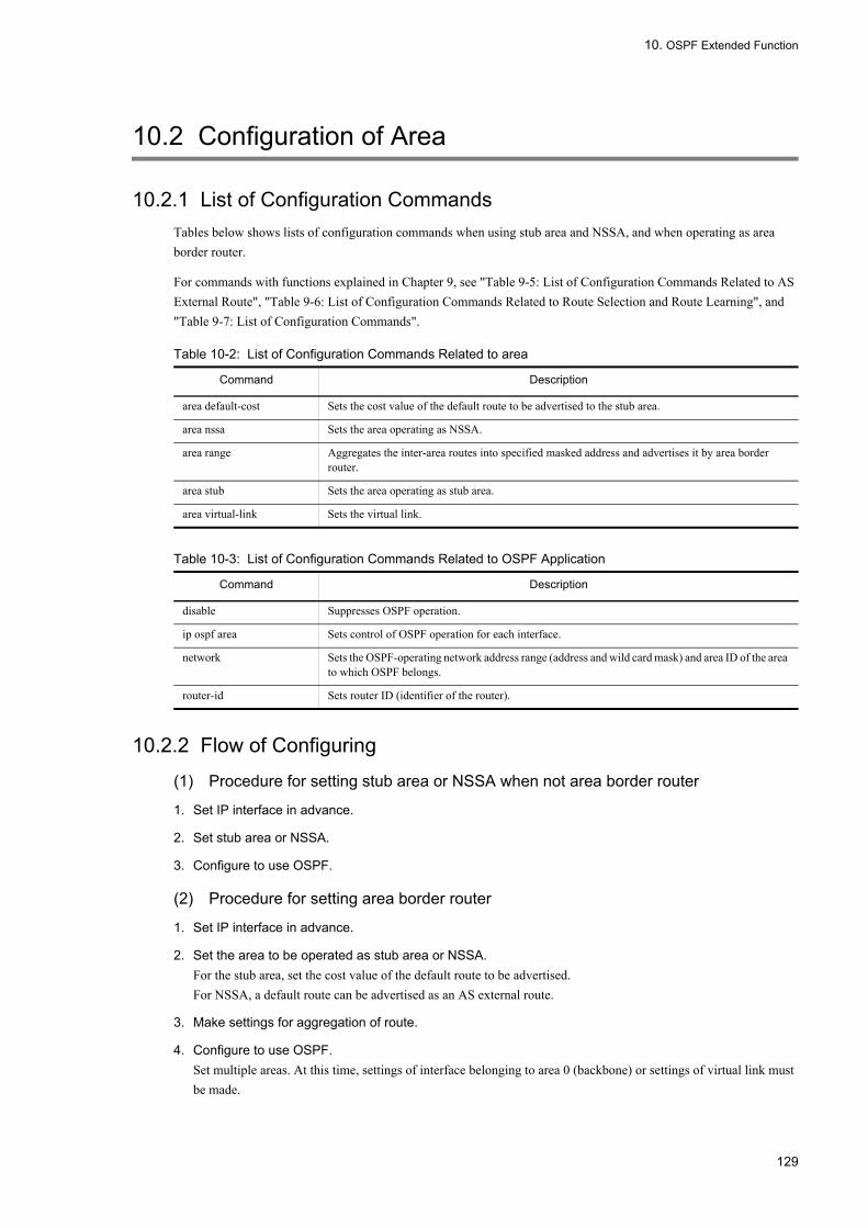
10. OSPF Extended Function
10.2 Configuration of Area
10.2.1 List of Configuration CommandsTables below shows lists of configuration commands when using stub area and NSSA, and when operating as area border router.
For commands with functions explained in Chapter 9, see "Table 9-5: List of Configuration Commands Related to AS External Route", "Table 9-6: List of Configuration Commands Related to Route Selection and Route Learning", and "Table 9-7: List of Configuration Commands".
Table 10-2: List of Configuration Commands Related to area
Table 10-3: List of Configuration Commands Related to OSPF Application
10.2.2 Flow of Configuring
(1) Procedure for setting stub area or NSSA when not area border router
1. Set IP interface in advance.
2. Set stub area or NSSA.
3. Configure to use OSPF.
(2) Procedure for setting area border router
1. Set IP interface in advance.
2. Set the area to be operated as stub area or NSSA.For the stub area, set the cost value of the default route to be advertised.For NSSA, a default route can be advertised as an AS external route.
3. Make settings for aggregation of route.
4. Configure to use OSPF.Set multiple areas. At this time, settings of interface belonging to area 0 (backbone) or settings of virtual link must be made.
Command Description
area default-cost Sets the cost value of the default route to be advertised to the stub area.
area nssa Sets the area operating as NSSA.
area range Aggregates the inter-area routes into specified masked address and advertises it by area border router.
area stub Sets the area operating as stub area.
area virtual-link Sets the virtual link.
Command Description
disable Suppresses OSPF operation.
ip ospf area Sets control of OSPF operation for each interface.
network Sets the OSPF-operating network address range (address and wild card mask) and area ID of the area to which OSPF belongs.
router-id Sets router ID (identifier of the router).
129

10. OSPF Extended Function
5. Set the virtual link.
10.2.3 Setting Stub Area[Point of setting]
Area border router advertises the default route into the area for which area stub command is set.Settings of stub area or NSSA must be made for all routers in the same area.
[Setup using commands]
1. (config)# router ospf 1
Moves to ospf mode. Sets the domain number to 1.
2. (config-router)# area 1 stub
Sets area 1 to stub area.
3. (config-router)# router-id 100.1.1.1
Uses 100.1.1.1 as router ID.
4. (config-router)# network 10.0.0.0 0.255.255.255 area 1
Specifies that the interface within the range of network 10.0.0.0/8 belongs to area 1.
10.2.4 Setting Area Border Router[Point of setting]
Advertisement to outside of network contained in this masked address range can be suppressed by specifying not-advertise parameter in area range command.The aggregated and suppressed address range can be set one or more for each area. Moreover, a router or network that uses the address not contained in any setting range can exist in an area. However, in configuring a network, the path information traffic of OSPF can be efficiently deleted without damaging the proper path to be selected when aggregation is set using the range corresponding to the topology after the address adapted to topology is assigned.
[Setup using commands]The following is an example of setting of route aggregation by the area border router belonging to areas 0 and 1.
1. (config)# router ospf 1
(config-router)# area 0 range 10.0.0.0 255.255.254.0
In area 0, advertises the aggregate route to area 1 when the route in the range of network 10.0.0.0 and mask 255.255.254.0 is learned.
2. (config-router)# area 1 range 10.0.2.0 255.255.255.0
In area 1, advertises the aggregate route to area 0 when the route in the range of network 10.0.2.0 and mask 255.255.255.0 is learned.
3. (config-router)# network 10.0.0.0 0.0.0.255 area 0
Specifies that the interface within the range of network 10.0.0.0/24 belongs to area 0.
4. (config-router)# network 10.0.2.0 0.0.0.255 area 1
Specifies that the interface within the range of network 10.0.2.0/24 belongs to area 1.
130

10. OSPF Extended Function
10.2.5 Setting Virtual Link[Point of setting]
Set the router ID of the remote router by area virtual-link command.
[Setup using commands]
1. (config)# router ospf 1
(config-router)# network 10.0.0.0 0.0.0.255 area 0
Specifies that the interface within the range of network 10.0.0.0/24 belongs to area 0.
2. (config-router)# network 10.0.2.0 0.0.0.255 area 1
Specifies that the interface within the range of network 10.0.2.0/24 belongs to area 1.
3. (config-router)# area 1 virtual-link 10.0.0.1
(config-router)# area 1 virtual-link 10.0.0.2
Sets the remote router in transit area 1.
131

10. OSPF Extended Function
10.3 Neighboring Router Authentication Overview
In OSPF, authentication can be used to verify that a router which transmitted information is under the same control during exchange of route information between routers. By using authentication between neighboring router, the router that is controlled by authentication can be protected from route control attacks when sending OSPF route information.
Authentication methodThe authentication of an OSPF packet is of two types: plaintext password authentication and MD5 authentication.Authentication method of area or method of authentication for each interface is specified in configuration. Authentication is not performed when neither configuration is specified. Also, authentication is not performed for the interface for which authentication key is not specified, even if authentication method is specified. Authentication method of the virtual link is that set for Area 0.
10.3.1 Authentication ProcedureThe authentication of an OSPF packet is of two types: plaintext password authentication and MD5 authentication.
(1) Plaintext password authentication
For plaintext password authentication, the authentication key set in configuration is embedded as password as is, at the time of transmitting the route information.
When receiving the route information, authentication is assumed successful if the password in the route information matches the authentication key previously set. The information that failed authentication is discarded.
(2) MD5 authentication
In MD5 authentication, information is authenticated by comparing message digests with the MD5 algorithm based on route information. The figure below shows the authentication process.
Figure 10-6: MD5 Authentication Data Flow
During transmission of route information, a message digest is generated from an authentication key, authentication key ID, and route information using MD5 hash algorithm and transmitted together with route information.
When route information is received, authentication keys with the same ID number as the ID number of the authentication key in the route information are tested among all authentication keys that are set in configuration. This authentication key is used to generate the message digest with the same procedure as the one used during transmission and authentication is assumed to be successful when the message digest generated from one of the authentication keys match the message digest received together with the route information. If authentication of the received information fails after using all valid keys, this information is assumed to have failed authentication. The information that failed authentication is discarded.
132

10. OSPF Extended Function
10.4 Configuration of Neighboring Router Authentication
10.4.1 List of Configuration CommandsThe configuration command list of neighboring router authentication is shown in the table below. Trap of reception of error packets such as authentication failure can be sent by setting SNMP configuration.
Table 10-4: List of Configuration Commands
10.4.2 Changing MD5 Authentication KeyTo change the authentication key, multiple MD5 authentication keys can be set.
To change a new key, follow the procedure below.
1. Set a new key with ID number different from the current ID number.
2. Set the new key for all neighboring routers.
3. Delete the old authentication key.
10.4.3 Setting Plaintext Password[Point of setting]
Use the area authentication command to set the authentication method of area.
[Setup using commands]
1. (config)# router ospf 1
(config-router)# area 1 authentication
(config-router)# exit
Specifies that plaintext password authentication is performed in area 1.
2. (config)# interface vlan 1
(config-if)# ip ospf authentication-key a1w@9a
Sets the authentication key to [email protected] VLAN1 is set for area 1, OSPF packets sent/received by VLAN1 are authenticated with plaintext password.
10.4.4 Setting MD5 Authentication[Point of setting]
Command Description
area authentication Sets authentication method (plaintext password or MD5 authentication).
area virtual-link Sets the authentication key (with authentication-key parameter).
area virtual-link message-digest-key Sets MD5 authentication key.
ip ospf authentication Sets authentication method (plaintext password or MD5 authentication).
ip ospf authentication-key Sets authentication key.
ip ospf message-digest-key Sets MD5 authentication key.
snmp-server host Sets the network management system to which trap is sent.
133

10. OSPF Extended Function
The authentication key itself and the authentication key ID number must be specified when setting an authentication key.
[Setup using commands]
1. (config)# router ospf 1
(config-router)# area 1 authentication message-digest
(config-router)# exit
Specifies that MD5 authentication is performed in area 1.
2. (config)# interface vlan 1
(config-if)# ip ospf message-digest-key 1 md5 a1w@9a
Sets ID No. to 1, and authentication key to a1w@9a. When VLAN1 is set for area 1, OSPF packets sent/received by VLAN1 are authenticated with message digest.
134

10. OSPF Extended Function
10.5 Graceful Restart Overview
10.5.1 Outline of Graceful RestartIn OSPF, the system that restarts the OSPF by graceful restart is called the restart router. The graceful restart function of the restart router is called the restart function. The neighboring system that assists graceful restart is called the helper router. The graceful restart function of the helper router is called the helper function.
The LANSW module supports the helper function.
10.5.2 Helper FunctionWhen the LANSW module is operating as a helper router, the route passing through the restart router is maintained while graceful restart is in progress.
(1) Helper function operating condition
The helper function operating conditions are as follows:
• The router is not already a helper of another restart router within the same domain. A router cannot function as a helper router for graceful restart of more than one router within the same domain. However, if there is only one restart router, it functions as helper router on all interfaces connected to that restart router.
• Not waiting for an Ack of OSPF Update packet sent to a restart router.
(2) Case when helper function fails
Operation as a helper router continues until neighbor is established or completion notice is received from the restart router.
However, if any of the following events occur, the helper function is interrupted and the route is recalculated because there may be a conflict with the route maintained by the restart router.
• A new LSA is learned from the neighboring router (excluding periodic update) and is advertised to the restart router.• The OSPF interface goes down.• LSA is updated by disconnection or establishment of neighbor adjacency with router other than the restart router.• Multiple routers are restarted simultaneously within the same OSPF domain.• When helper function is deleted by deleting configuration with graceful-restart mode command.
10.5.3 Opaque LSAType9 Opaque LSA is learned and advertised at start/end of graceful restart.
The following restrictions are applied to Opaque LSA.
• For Type9 Opaque LSA, functions other than grace-LSA used for OSPF graceful restart are not supported.• Type10, Type11 Opaque LSA learning and advertising are not supported.
135

10. OSPF Extended Function
10.6 Configuration of Graceful Restart
10.6.1 List of Configuration CommandsWhen using the OSPF restart function on the OSPF neighboring router of the LANSW module, configure the OSPF helper function on the LANSW module.
The graceful restart configuration command list is shown in the table below.
Table 10-5: List of Configuration Commands
10.6.2 Setting Helper Function[Point of setting]
Specify the helper function to be used. If omitted, the router does not operate.
[Setup using commands]
1. (config)# router ospf 1
(config-router)# graceful-restart mode helper
Enables helper function.
Command Description
graceful-restart mode Sets the helper function.
graceful-restart strict-lsa-checking Stops graceful restart if the LSA databases are not synchronized between the helper router and restart router.
136

10. OSPF Extended Function
10.7 Stub Router Overview
10.7.1 Outline of Stub RouterIf connection with the neighboring router is not completed or stabilized, routing of the entire network may become instable. When the router is being started or restarted or a router is being added to the network, such a situation may arise. Under such circumstances, OSPF can notify the route information in such a way that surrounding systems will use the information for routing as less as possible. In OSPF, the router making such a notification is called the stub router. Using this function, you can prevent network routing from becoming instable even though the system status is instable.
(1) Max metric
The stub router advertises the cost value of the connected OSPF interface as the maximum value (65535). Therefore, the OSPF route that passes through the stub router does not take precedence.
However, for the route of the interface for which no neighboring router exists (stub network), the cost value specified using the configuration command is advertised. The route advertised by the stub router may take precedence over the stub network or AS external route.
Surrounding systems compare the metrics and prefer the alternative route that does not pass through the stub router. Using the system address of the stub router itself, management via telnet or SNMP or route exchange via BGP4 is allowed.
10.7.2 Stub Router OperationConfiguration command max-metric router-lsa specifies whether the stub router function runs for each domain. Further, whether the stub router always runs or runs after the start can be selected as the operation condition.
(1) If the stub router always runs
The cost is always set to the maximum value. The stub router keeps on running until the stub router configuration is deleted.
(2) If the stub router runs after the start
In the timing below, the cost is set to the maximum value. The stub router keeps on running until the deadline specified in the configuration elapses.
• After restart of the routing program• System start
The stub router can be stopped by executing operation command clear ip ospf stub-router during operation or deleting the configuration. The stub router operation is shown in the figure below.
137

10. OSPF Extended Function
Figure 10-7: Stub Router Operation
(3) Notes
1. When the stub router is running as the helper router for graceful restart, do not change the stub router configuration. If the configuration is changed, the stub router may start or stop running and the helper action may fail.
2. If the stub router that is set to always run is changed to run after the start, the stub router is immediately ended.3. The virtual link that passes through the sub router is not available.
If the cost in the transit area is higher than 65535, the virtual link assumed that the virtual link is unreachable.4. In the RFC1247 specifications as the old OSPF standard, the maximum metric route information is not used for SPF
calculation. Therefore, if the LANSW module does not support the new OSPF standard, the route that passes through the stub router is not registered.
138

10. OSPF Extended Function
10.8 Configuration of Stub Router
10.8.1 List of Configuration CommandsIf you do not prefer the route that passes through the LANSW module, set the stub router.
The metric of the route that passes through the stub router can be increased.
The following table lists the stub router configuration commands:
Table 10-6: List of Configuration Commands
10.8.2 Stub Router Function[Point of setting]
Specify the stub router operation. If the on-startup parameter is not specified, the stub router always runs.
[Setup using commands]
1. (config)# router ospf 1
(config-router)# max-metric router-lsa
Uses the stub router function.
Command Description
max-metric router-lsa Runs as the stub router.
139

10. OSPF Extended Function
10.9 Operation of OSPF Extended Function
10.9.1 List of Operation CommandsTable below shows the OSPF extended function operation command list.
Table 10-7: List of Operation Commands
10.9.2 Checking Area BorderFor area border router, execute operation command show ip ospf to check that router type (Flags) contains "AreaBorder".
Also check whether route aggregation between areas is correctly reflected.
Figure 10-8: Execution Result of show ip ospf Command
>show ip ospfDate 2005/07/14 12:00:00 UTCOSPF protocol: ON Domain: 1Router ID: 172.16.1.1Distance:Intra Area: 10, Inter Area: 10, External: 150Flags: <AreaBorder ASBoundary>SPF Interval: 7s, SPF Delay: 3sGraceful Restart: Helper Helper Status : Finished 2004/02/15 14:12:22Area Interfaces Network Range State0 1 - -10 1 192.168.1/24 Advertise 172.19/18 DoNotAdvertise
10.9.3 Checking AreaCheck whether the area set in configuration is correctly reflected. When area parameter is specified in operation command show ip ospf, a list of areas is displayed.
Figure 10-9: Execution Result of show ip ospf area Command
>show ip ospf areaDate 2005/07/14 12:00:00 UTCDomain: 1ID Neighbor SPFcount Flags0 2 14 <ASBoundary>1 2 8 <NSSA>>
10.9.4 Checking Graceful RestartExecute show ip ospf command to check the graceful restart state.
Command Description
show ip ospf Displays domain information (area border state, graceful restart state, etc.) or area.
clear ip ospf stub-router Stops the stub router operation.
140

10. OSPF Extended Function
Figure 10-10: Execution Result of show ip ospf Command
>show ip ospfDate 2005/07/14 12:00:00 UTCOSPF protocol: ON Domain: 1Router ID: 172.16.1.1Distance:Intra Area: 10, Inter Area: 10, External: 150Flags: <AreaBorder ASBoundary>SPF Interval: 7s, SPF Delay: 3sGraceful Restart: Helper Helper Status : Finished 2004/02/15 14:12:22Area Interfaces Network Range State0 1 - -10 1 192.168.1/24 Advertise
141

10. OSPF Extended Function
142

11. BGP4
11BGP4 This chapter provides explanation of the IPv4 routing protocol BGP4 and describes how to operate it.
11.1 Basic Function Overview
11.2 Configuration of Basic Functions
11.3 Operation of Basic Function
11.4 Extended Function Overview
11.5 Configuration of Extended Function
11.6 Operation of Extended Function
143
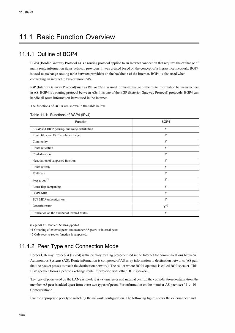
11. BGP4
11.1 Basic Function Overview
11.1.1 Outline of BGP4BGP4 (Border Gateway Protocol 4) is a routing protocol applied to an Internet connection that requires the exchange of many route information items between providers. It was created based on the concept of a hierarchical network. BGP4 is used to exchange routing table between providers on the backbone of the Internet. BGP4 is also used when connecting an intranet to two or more ISPs.
IGP (Interior Gateway Protocol) such as RIP or OSPF is used for the exchange of the route information between routers in AS. BGP4 is a routing protocol between ASs. It is one of the EGP (Exterior Gateway Protocol) protocols. BGP4 can handle all route information items used in the Internet.
The functions of BGP4 are shown in the table below.
Table 11-1: Functions of BGP4 (IPv4)
(Legend) Y: Handled N: Unsupported*1 Grouping of external peers and member AS peers or internal peers*2 Only receive router function is supported.
11.1.2 Peer Type and Connection ModeBorder Gateway Protocol 4 (BGP4) is the primary routing protocol used in the Internet for communications between Autonomous Systems (AS). Route information is composed of AS array information to destination networks (AS path that the packet passes to reach the destination network). The router where BGP4 operates is called BGP speaker. This BGP speaker forms a peer to exchange route information with other BGP speakers.
The type of peers used by the LANSW module is external peer and internal peer. In the confederation configuration, the member AS peer is added apart from these two types of peers. For information on the member AS peer, see "11.4.10 Confederation".
Use the appropriate peer type matching the network configuration. The following figure shows the external peer and
Function BGP4
EBGP and IBGP peering, and route distribution Y
Route filter and BGP attribute change Y
Community Y
Route reflection Y
Confederation Y
Negotiation of supported function Y
Route refresh Y
Multipath Y
Peer group*1 Y
Route flap dampening Y
BGP4 MIB Y
TCP MD5 authentication Y
Graceful restart Y*2
Restriction on the number of learned routes Y
144

11. BGP4
internal peer.
Figure 11-1: Internal and External Peers
(1) External peer
External peers are peers formed between BGP speakers belonging to different ASs. The interface address of the directly connected interface is used as the IP address for peering. By using the configuration command neighbor ebgp-multihop, connection is possible with addresses other than the interface address of directly connected interface (such as system address).
Peers formed between Router 1 and Router 6, Router 2 and Router 7, and Router 3 and Router 8 shown in "Figure 11-1: Internal and External Peers" are external peers.
(2) Internal peer
An internal peer is a peer formed between BGP speakers that belong to the same AS. BGP4 uses TCP (port 179) to establish connections among peers. Therefore, an internal peer has to be logically full-meshed with each BGP speaker within an AS, though not all BGP speakers need to be connected physically full-meshed. This is done because the route received by internal peer is not advertised to other internal peers. This condition is loosened when the route reflection or confederation function is used.
Peers formed between Router 1 and Router 2, Router 1 and Router 3, and Router 2 and Router 3 shown in "Figure 11-1: Internal and External Peers" are internal peers.
(3) Peering using system address
The LANSW module can eliminate influences on peering (TCP connection) depending on a specific physical interface state, by using the IP address of the loopback interface (this is called system address) as the IP address of an external or internal peer.
For example, when the interface IP address is used for an internal peer between routers Router 1 and Router 2 as shown above in "Figure 11-1: Internal and External Peers" and failure occurs between them so that the interface cannot be used, an internal peer relationship between Router 1 and Router 2 cannot be established. By using the system address as an internal peer IP address, an internal peer relationship can be established via Router 4 and Router 5 even when the interface between Router 1 and Router 2 cannot be used.
[Notes on using a system address]
145

11. BGP4
Prior to using a system address, the subject routers must mutually be informed of the route information to the system on the static or Interior Gateway Protocol (IGP), e.g., RIP or OSPF interface. The LANSW module handles the system address as directly connected route information.
[Note on the case of going through the non-BGP speaker in the internal peer]Regarding passing non-BGP speakers by internal peer, when the route information is advertised via a non-BGP speaker by a routing peer (for example, advertisement from router Router 2 to router Router 3), the route information has to be learned by the non-BGP speaker via Interior Gateway Protocol (IGP). This must be done to keep IP packets going to a particular destination, coming from the destination BGP speaker by advertisement of particular route information, from being discarded by a non-BGP speaker router where the applicable route is not learned. For example, "Figure 11-1: Internal and External Peers" preventing IP packets coming from Router 3 to Router 5 from being discarded by Router 5.
11.1.3 Route SelectionThe LANSW module selects the best route from the routes to the same destination learned by each protocol according to independent route selection procedure. When multiple routes to the same destination exists, the distance value for each route is compared, at which time the route with the highest priority is selected.
In BGP4, using the priority settings in the following table, the best route is selected from multiple routes leading to the same destination learned using its own protocol. Then, when multiple route information items to the same destination exist by route selection in each protocol (RIP, OSPF, and static), the distance value of each route information is compared and the route information with the highest priority is set in the routing table.
For route selection in the confederation configuration, see "11.4.10 Confederation".
Table 11-2: Route Selection Priority
*1The path type of the AS_PATH attributes, AS_SET is counted as one AS.
*2The route selection by MED value is effective only for the redundant route learned from the same neighboring AS. However, by specifying the configuration command bgp always-compare-med, it is also valid for redundant routes learned from different adjacent AS.
*3If the values of the remote BGP identifiers (router IDs) are different between the routes received from the external peer, route selection with the remote BGP identifier (router ID) and learning source peer address is not performed, but the already selected route is adopted. Route selection with the remote BGP identifier (router ID) is possible even if values of remote BGP identifiers
Precedence Contents
High↑
↓Low
Selects the route with the largest weight value.
Selects the route that has the largest LOCAL_PREF attribute value.
Selects the route that has the shortest number of ASs in AS_PATH attribute.*1
Selects using the ORIGIN attribute value in the order of IGP, EGP, and Incomplete.
Selects the route that has the smallest MED attribute value.*2
Selects in the order of route learned in external peer, and route learned in internal peer.
Selects the route that has the closest next-hop address value (the smallest metric value of IGP route used at next-hop solution.
Selects the route that has the smallest BGP identifier (router ID) at the other end.*3
Selects a route with a smaller learning source peer address.*3
146
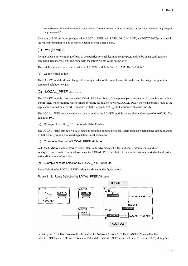
11. BGP4
(router IDs) are different between the routes received from the external peer by specifying configuration command "bgp bestpath compare-routerid".
Concepts of BGP attributes (weight value, LOCAL_PREF, AS_PATH, ORIGIN, MED, and NEXT_HOP) contained in the route information related to route selection are explained below.
(1) weight value
Weight value is for weighting of path to be specified for each learning source peer, and set by using configuration command neighbor weight. The route with the larger weight value has priority.
The weight value that can be used with the LANSW module is from 0 to 255. The default is 0.
(a) weight modification
The LANSW module allows change of the weight value of the route learned from the peer by using configuration command neighbor weight.
(2) LOCAL_PREF attribute
The LANSW module can change the LOCAL_PREF attribute of the reported path information in combination with an export filter. When multiple routes exist to the same destination network, LOCAL_PREF shows the priority route to the applicable destination network. The route with the larger LOCAL_PREF attribute value has priority.
The LOCAL_PREF attribute value that can be used in the LANSW module is specified in the range of 0 to 65535. The default is 100.
(a) Change of LOCAL_PREF attribute default value
The LOCAL_PREF attribute value of route information imported to local system from an external peer can be changed with the configuration command bgp default-local preference.
(b) Change in filter unit of LOCAL_PREF attribute
With the LANSW module, learned route filter, route advertisement filter, and configuration command set local-preference can be combined to change the LOCAL_PREF attribute of route information imported to local system and notified route information.
(c) Example of route selection by LOCAL_PREF attribute
Route Selection by LOCAL_PREF attribute is shown in the figure below.
Figure 11-2: Route Selection by LOCAL_PREF Attribute
In this figure, AS400 receives route information for Network A from AS200 and AS300. Assume that the LOCAL_PREF value of Router D is set to 150 and the LOCAL_PREF value of Router E is set to 50. By doing this,
147

11. BGP4
when the route information from AS 200 is advertised to Router F, Router D's LOCAL_PREF value is set to 150. When the route information from AS 300 is advertised to Router F, the LOCAL_PREF value is set to 50. With the route information from Network A in Router F, the route from Router D is selected because the route from Router D has a larger LOCAL_PREF attribute value than the route from Router E.
(3) ORIGIN attribute
The ORIGIN attribute indicates the origin of the route. It uses one of three values shown in the table below.
Table 11-3: ORIGIN Attribute
In the selection of route, if multiple routes having the same destination exist, select in the order of IGP, EGP, Incomplete.
(a) ORIGIN attribute modification
With the LANSW module, learned route filter, route advertisement filter, and configuration command set origin can be combined to change the ORIGIN attribute of route information imported to local system and notified route information.
(4) AS_PATH attribute
AS_PATH attributes are the list of AS numbers that the route passes until the destination network is reached. When the route is advertised to another AS, the local AS number is added to the AS_PATH attribute of that route information. Also, by combining the learning filter information and advertising filter information with configuration command set as-path prepend count, multiple local AS numbers can be added to the AS_PATH attribute. This is valid for the selection of a specific path when multiple routes to a certain destination network exist.
(a) Example of route selection by AS_PATH attribute
The route selection using an AS_Path attribute is shown in the figure below.
Figure 11-3: Route Selection by AS_PATH Attribute
The AS_PATH attribute of route information that reaches AS500 has "200 100" when Router A notifies Network A existing in local AS through AS200. The AS_PATH attribute of route information that reaches AS500 has "400 300 100" when Router A notifies Network A in local AS through AS300 and AS400. Therefore, Router E of AS500 selects the route that reaches through AS200 that has the shortest AS_PATH attribute.
ORIGIN Attribute Contents
IGP Indicates that the applicable route is generated in AS.
EGP Indicates that the applicable route is learned via Exterior Gateway Protocol (EGP).
Incomplete Indicates that the applicable route is learned by method other than ones described above.
148

11. BGP4
(b) Route selection using set as-path prepend count command
The following figure shows an example of configuration command set as-path prepend count.
Figure 11-4: Example of Using set as-path prepend count Command
In this figure, multiple local AS numbers are added to the AS_PATH attribute of the route information notified to AS200 when Router A requests Router E to select a route through AS300 and AS400. For example, the AS_PATH attribute of route information that reaches AS500 through AS200 has "200 100 100 100" when three local AS numbers are added. Router E selects a route that reaches through AS300 and AS400 that have the shortest AS_PATH attribute.
(5) MED attribute
The MED attribute determines the priority of the route between adjacent ASs. It is used to select the priority route to a neighbor AS when multiple routes from the same AS exist for a particular destination network. The path information that is lower in a MED attribute value has priority. It can be used to select the priority between the BGP4 routes learned from different neighboring ASs by specifying configuration command bgp always-compare-med.
(a) Example of route selection using MED attribute
An example of the route selection by MED attribute is shown in the figure below.
Figure 11-5: Example of Route Selection by MED Attribute
Router C advertises the route for a particular destination network to Router A with a MED attribute value of 10. Router D advertises the route for the same destination network to Router A with a MED attribute value of 20. In this case, Router A selects the route with the smaller MED value of 10 advertised by Router C as the route to the destination network.
(b) MED attribute modification
With the LANSW module, learning filter, advertising filter, and configuration command set metric can be combined to change the MED attribute of route information imported to local system and notified route information.
149
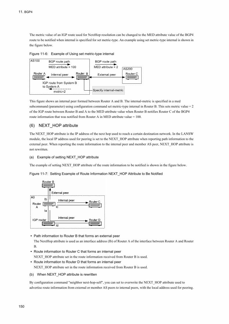
11. BGP4
The metric value of an IGP route used for NextHop resolution can be changed to the MED attribute value of the BGP4 route to be notified when internal is specified for set metric-type. An example using set metric-type internal is shown in the figure below.
Figure 11-6: Example of Using set metric-type internal
This figure shows an internal peer formed between Router A and B. The internal-metric is specified in a med subcommand (parameter) using configuration command set metric-type internal in Router B. This sets metric value = 2 of the IGP route between Router B and A to the MED attribute value when Router B notifies Router C of the BGP4 route information that was notified from Router A in MED attribute value = 100.
(6) NEXT_HOP attribute
The NEXT_HOP attribute is the IP address of the next hop used to reach a certain destination network. In the LANSW module, the local IP address used for peering is set to the NEXT_HOP attribute when reporting path information to the external peer. When reporting the route information to the internal peer and member AS peer, NEXT_HOP attribute is not rewritten.
(a) Example of setting NEXT_HOP attribute
The example of setting NEXT_HOP attribute of the route information to be notified is shown in the figure below.
Figure 11-7: Setting Example of Route Information NEXT_HOP Attribute to Be Notified
• Path information to Router B that forms an external peerThe NextHop attribute is used as an interface address (Ib) of Router A of the interface between Router A and Router B.
• Route information to Router C that forms an internal peerNEXT_HOP attribute set in the route information received from Router B is used.
• Route information to Router D that forms an internal peerNEXT_HOP attribute set in the route information received from Router B is used.
(b) When NEXT_HOP attribute is rewritten
By configuration command "neighbor next-hop-self", you can set to overwrite the NEXT_HOP attribute used to advertise route information from external or member AS peers to internal peers, with the local address used for peering.
150
11. BGP4
By configuration command "neighbor always-nexthop-self", you can set to overwrite the NEXT_HOP attribute for advertisement to internal peers including route reflection with the local address used for peering. Also by configuration command "neighbor set-nexthop-peer", you can set to overwrite the NEXT_HOP attribute of learned route with the address of the peer router.
(c) Resolution of NEXT_HOP attribute
When BGP4 route information is learned from an internal peer, the path to reach an address indicated by NEXT_HOP attribute is resolved with IGP route, static route, direct-connection route, and BGP4 route. The route with longest destination mask length is selected from the routes reachable to BGP4 route next hop, and the path of that route is used as BGP4 route path. Using configuration command "bgp nexthop", the protocol type and prefix of the route to be used for NEXT_HOP attribute resolution can be specified.
If the route used to resolve next hop is static route and noinstall parameter is specified, the BGP4 route is suppressed.
11.1.4 Notes on Using BGP4Pay attention to the limitations below when configuring a network in which BGP4 is used.
(1) Limitations on BGP4
The LANSW module conforms to RFC1771 (BGP version 4 specifications), RFC1997 (community specifications), RFC2842 (advertisement specifications of a support function), and RFC2918 (route refresh specifications), RFC2796 (route reflection specification) and RFC1965 (confederation specification), but deviates from some RFCs due to software limitations. The deviation from RFC is shown in the table below. The LANSW module supports only BGP version 4.
151
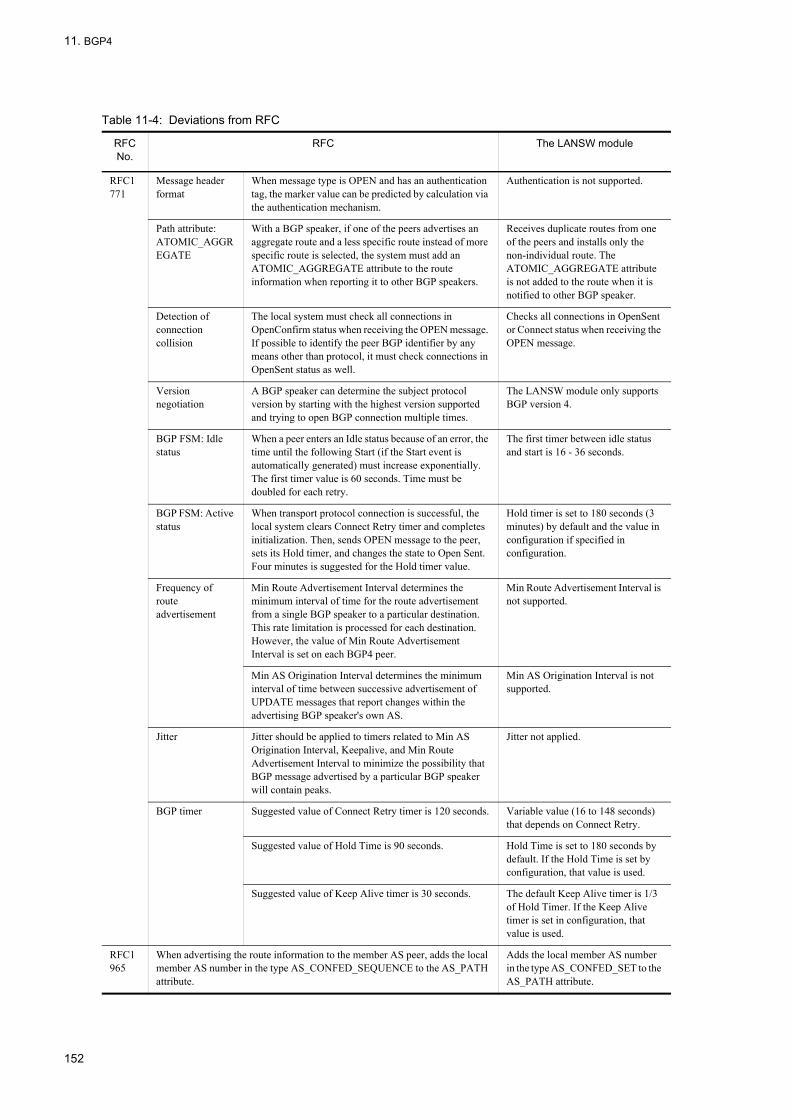
11. BGP4
Table 11-4: Deviations from RFC
RFC No.
RFC The LANSW module
RFC1771
Message header format
When message type is OPEN and has an authentication tag, the marker value can be predicted by calculation via the authentication mechanism.
Authentication is not supported.
Path attribute: ATOMIC_AGGREGATE
With a BGP speaker, if one of the peers advertises an aggregate route and a less specific route instead of more specific route is selected, the system must add an ATOMIC_AGGREGATE attribute to the route information when reporting it to other BGP speakers.
Receives duplicate routes from one of the peers and installs only the non-individual route. The ATOMIC_AGGREGATE attribute is not added to the route when it is notified to other BGP speaker.
Detection of connection collision
The local system must check all connections in OpenConfirm status when receiving the OPEN message. If possible to identify the peer BGP identifier by any means other than protocol, it must check connections in OpenSent status as well.
Checks all connections in OpenSent or Connect status when receiving the OPEN message.
Version negotiation
A BGP speaker can determine the subject protocol version by starting with the highest version supported and trying to open BGP connection multiple times.
The LANSW module only supports BGP version 4.
BGP FSM: Idle status
When a peer enters an Idle status because of an error, the time until the following Start (if the Start event is automatically generated) must increase exponentially. The first timer value is 60 seconds. Time must be doubled for each retry.
The first timer between idle status and start is 16 - 36 seconds.
BGP FSM: Active status
When transport protocol connection is successful, the local system clears Connect Retry timer and completes initialization. Then, sends OPEN message to the peer, sets its Hold timer, and changes the state to Open Sent. Four minutes is suggested for the Hold timer value.
Hold timer is set to 180 seconds (3 minutes) by default and the value in configuration if specified in configuration.
Frequency of route advertisement
Min Route Advertisement Interval determines the minimum interval of time for the route advertisement from a single BGP speaker to a particular destination. This rate limitation is processed for each destination. However, the value of Min Route Advertisement Interval is set on each BGP4 peer.
Min Route Advertisement Interval is not supported.
Min AS Origination Interval determines the minimum interval of time between successive advertisement of UPDATE messages that report changes within the advertising BGP speaker's own AS.
Min AS Origination Interval is not supported.
Jitter Jitter should be applied to timers related to Min AS Origination Interval, Keepalive, and Min Route Advertisement Interval to minimize the possibility that BGP message advertised by a particular BGP speaker will contain peaks.
Jitter not applied.
BGP timer Suggested value of Connect Retry timer is 120 seconds. Variable value (16 to 148 seconds) that depends on Connect Retry.
Suggested value of Hold Time is 90 seconds. Hold Time is set to 180 seconds by default. If the Hold Time is set by configuration, that value is used.
Suggested value of Keep Alive timer is 30 seconds. The default Keep Alive timer is 1/3 of Hold Timer. If the Keep Alive timer is set in configuration, that value is used.
RFC1965
When advertising the route information to the member AS peer, adds the local member AS number in the type AS_CONFED_SEQUENCE to the AS_PATH attribute.
Adds the local member AS number in the type AS_CONFED_SET to the AS_PATH attribute.
152
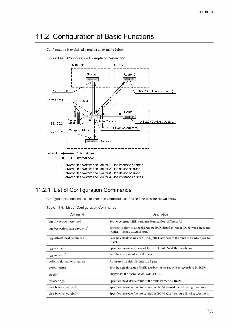
11. BGP4
11.2 Configuration of Basic Functions
Configuration is explained based on an example below.
Figure 11-8: Configuration Example of Connection
11.2.1 List of Configuration CommandsConfiguration command list and operation command list of basic functions are shown below.
Table 11-5: List of Configuration Commands
Command Description
bgp always-compare-med Sets to compare MED attributes learned from different AS.
bgp bestpath compare-routerid* Sets route selection using the remote BGP identifier (router ID) between the routes learned from the external peer.
bgp default local-preference Sets the default value of LOCAL_PREF attribute of the route to be advertised by BGP4.
bgp nexthop Specifies the route to be used for BGP4 route Next Hop resolution.
bgp router-id* Sets the identifier of a local router.
default-information originate Advertises the default route to all peers.
default-metric Sets the default value of MED attribute of the route to be advertised by BGP4.
disable* Suppresses the operation of BGP4/BGP4+.
distance bgp Specifies the distance value of the route learned by BGP4.
distribute-list in (BGP) Specifies the route filter to be used as BGP4 learned route filtering conditions.
distribute-list out (BGP) Specifies the route filter to be used as BGP4 advertise route filtering conditions.
153
11. BGP4
* Command common to BGP4+ (IPv6)
Table 11-6: Operation Command List for Configuration
11.2.2 Flow of Configuring1. Set IPv4 interface in advance.
2. Configure local system address to loopback interface in advance.
3. Set BGP4 peers.
neighbor description Sets the supplementary description of peer.
neighbor distribute-list in (BGP) Specifies the route filter to be used as learned route filtering conditions for specific BGP4 peer only.
neighbor distribute-list out (BGP) Specifies the route filter to be used as advertise route filtering conditions for specific BGP4 peer only.
neighbor ebgp-multihop Sets to allow the external peer not directly connected by the interface to connect the member AS peer.
neighbor next-hop-self Sets so that NEXT_HOP attribute is rewritten to the local address used for peering when the route learned from an external peer and member AS peer is advertised to an internal peer.
neighbor remote-as Sets BGP4/BGP4+ peer.
neighbor route-map in (BGP) Specifies the route filter to be used as learned route filtering conditions for specific BGP4 peer only.
neighbor route-map out (BGP) Specifies the route filter to be used as advertise route filtering conditions for specific BGP4 peer only.
neighbor shutdown Suppresses peer connection.
neighbor soft-reconfiguration Retains route suppressed by input policy.
neighbor timers Sets the KEEPALIVE message transmission interval and hold timer value used for connection with peers.
neighbor update-source Sets the system address as the local address used for peering.
neighbor weight Sets the weight of route learned from peers.
redistribute (BGP) Specifies the protocol of the route to be advertised by BGP4.
router bgp* Sets the operation information concerning the routing protocol BGP4/BGP4+.
timers bgp* Sets the KEEPALIVE message transmission interval and hold timer value applied to all peers.
Command Description
clear ip bgp 1. When * in is specified in the parameter- Applies the latest route filtering settings to BGP4 learned route filtering.- Requests re-advertising of BGP4 route to all BGP4 peers.
2. When * out is specified in the parameter- Applies the latest route filtering settings to BGP4 route advertisement filtering.- Re-advertises BGP4 route to all BGP4 peers.
3. When * both is specified in the parameter- Applies the latest route filtering settings to BGP4 learned route filtering and route advertisement filtering.- Requests advertising of BGP4 route to all BGP4 peers and re-advertises.
4. When * is specified in the parameterAll BGP4 peers are disconnected.
Command Description
154

11. BGP4
4. Set learning policy of BGP4 route.
5. Set advertisement policy of BGP4 route.
6. Configure the learned route filter.
7. Configure the route advertisement filter.
8. Configure the learned route filtering condition.
9. Configure the route advertisement filtering condition.
10.Apply the filter.
[Note]When configuration of route filtering is not set at the setting of BGP4 peer configuration, the route is automatically learned and advertised as soon as the peer is established. To suppress unintended learning and advertisement of route, set configuration command disable to suppress operation of BGP4 before setting configuration command neighbor remote-as. To operate BGP4 after setting configuration of route filtering, delete configuration command disable.
11.2.3 Setting BGP4 Peer[Point of setting]
When setting the peer, first use neighbor remote-as command to set the remote address and remote AS number, and then set other information of the peer.
[Setup using commands]
1. (config)#router bgp 65531
Applies BGP4/BGP4+ to the routing protocol. Specify the AS number (65531) to which the local router belongs as parameter.
2. (config-router#) bgp router-id 192.168.1.100
Sets the local router identifier (192.168.1.100).
3. (config-router)#neighbor 172.16.2.2 remote-as 65532
Sets the external peer (remote address: 172.16.2.2, AS number: 65532).
4. (config-router)#neighbor 10.2.2.2 remote-as 65533
Sets the external peer (remote address: 10.2.2.2, AS number: 65533).
5. (config-router)#neighbor 10.2.2.2 ebgp-multihop
Sets that the interface address of the directly-connected interface is not used as the address used for peering.
6. (config-router)#neighbor 10.2.2.2 update-source loopback 0
Specifies the System address as the local address used for peering.
7. (config-router)#neighbor 192.168.2.2 remote-as 65531
Sets the internal peer (remote address: 192.168.2.2).
8. (config-router)#neighbor 10.1.2.2 remote-as 65531
Sets the internal peer (remote address: 10.1.2.2).
9. (config-router)#neighbor 10.1.2.2 update-source loopback 0
155

11. BGP4
Specifies the system address as the local address used for peering.
11.2.4 Setting BGP4 Route Learning Policy[Point of setting]
When setting the priority of learned route for each peer, set weight value for each peer.
[Setup using commands]
1. (config-router)# bgp always-compare-med
Also compares the MED attribute of route received from different AS during route selection.
2. (config-router)# neighbor 172.16.2.2 weight 20
(config-router)# neighbor 10.2.2.2 weight 20
(config-router)# neighbor 10.1.2.2 weight 10
(config-router)# neighbor 192.168.2.2 weight 10
Specifies weight of router learned from each peer.Gives priority to routes learned from external peer over routes learned from internal peer.
11.2.5 Setting BGP4 Route Advertising Policy[Point of setting]
Set the path attribute of BGP4 to be used for route selection by advertisement destination router.
[Setup using commands]
1. (config-router)# default-metric 100
Sets the MED attribute value of the advertised route to 100.
2. (config-router)# bgp default local-preference 80
(config-router)# exit
Sets the LOCAL_PREF attribute advertised to internal peer to 80.
11.2.6 Setting Learned Route Filter[Point of setting]
When setting the priority of learned BGP4 route, use route-map to specify the conditions and setting value.
[Setup using commands]
1. (config)# ip prefix-list EXT_IN seq 10 permit 10.10.0.0/16
(config)# route-map SET_LOCPREF_IN permit 10
(config-route-map)# match ip address prefix-list EXT_IN
(config-route-map)# set local-preference 120
(config-route-map)# exit
(config)# route-map SET_LOCPREF_IN permit 20
(config-route-map)# exit
Sets 120 for LOCAL_PREF attribute value to be destined to network 10.10.0.0/16.
2. (config)# ip as-path access-list 10 permit "_65529$"
156

11. BGP4
(config)# route-map SET_ASPREPEND_IN permit 10
(config-route-map)# match as-path 10
(config-route-map)# set as-path prepend count 1
(config-route-map)# exit
(config)# route-map SET_ASPREPEND_IN permit 20
(config-route-map)# exit
Increments AS number in AS arrangement by one when the end of AS arrangement of AS_PATH attribute is 65529.
3. (config)# ip prefix-list INT_IN_1 seq 10 permit 172.20.0.0/16
(config)# route-map SET_ORIGIN_IN permit 10
(config-route-map)# match ip address prefix-list INT_IN_1
(config-route-map)# set origin incomplete
(config-route-map)# exit
(config)# route-map SET_ORIGIN_IN permit 20
(config-route-map)# exit
Sets INCOMPLETE for ORIGIN attribute when the destination network is 172.20.0.0/16.
4. (config)# ip prefix-list INT_IN_2 seq 10 permit 172.30.0.0/16
(config)# route-map SET_MED_IN permit 10
(config-route-map)# match ip address prefix-list INT_IN_2
(config-route-map)# set metric 100
(config-route-map)# exit
(config)# route-map SET_MED_IN permit 20
(config-route-map)# exit
Sets 100 for MED attribute when the destination network is 172.30.0.0/16.
11.2.7 Setting Route Advertisement Filter[Point of setting]
Use route-map to specify the criteria and value when setting priority of advertised BGP4+ routes.
[Setup using commands]
1. (config)# ip prefix-list MY_NET_1 seq 10 permit 192.169.10.0/24
(config)# ip prefix-list MY_NET_2 seq 10 permit 192.169.20.0/24
(config)# route-map SET_EXT_OUT permit 10
(config-route-map)# match ip address prefix-list MY_NET_1
(config-route-map)# set metric 120
(config-route-map)# exit
(config)# route-map SET_EXT_OUT permit 20
(config-route-map)# match ip address prefix-list MY_NET_2
(config-route-map)# exit
Sets 120 for MED attribute when the destination network is 192.169.10.0/24.Destination network 192.169.20.0/24 is also subject to advertisement.
11.2.8 Setting Learned Route Filtering Criteria[Point of setting]
157
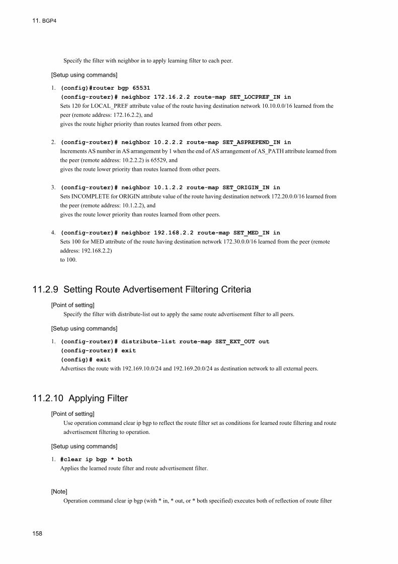
11. BGP4
Specify the filter with neighbor in to apply learning filter to each peer.
[Setup using commands]
1. (config)#router bgp 65531
(config-router)# neighbor 172.16.2.2 route-map SET_LOCPREF_IN in
Sets 120 for LOCAL_PREF attribute value of the route having destination network 10.10.0.0/16 learned from the peer (remote address: 172.16.2.2), andgives the route higher priority than routes learned from other peers.
2. (config-router)# neighbor 10.2.2.2 route-map SET_ASPREPEND_IN in
Increments AS number in AS arrangement by 1 when the end of AS arrangement of AS_PATH attribute learned from the peer (remote address: 10.2.2.2) is 65529, andgives the route lower priority than routes learned from other peers.
3. (config-router)# neighbor 10.1.2.2 route-map SET_ORIGIN_IN in
Sets INCOMPLETE for ORIGIN attribute value of the route having destination network 172.20.0.0/16 learned from the peer (remote address: 10.1.2.2), andgives the route lower priority than routes learned from other peers.
4. (config-router)# neighbor 192.168.2.2 route-map SET_MED_IN in
Sets 100 for MED attribute of the route having destination network 172.30.0.0/16 learned from the peer (remote address: 192.168.2.2) to 100.
11.2.9 Setting Route Advertisement Filtering Criteria[Point of setting]
Specify the filter with distribute-list out to apply the same route advertisement filter to all peers.
[Setup using commands]
1. (config-router)# distribute-list route-map SET_EXT_OUT out
(config-router)# exit
(config)# exit
Advertises the route with 192.169.10.0/24 and 192.169.20.0/24 as destination network to all external peers.
11.2.10 Applying Filter[Point of setting]
Use operation command clear ip bgp to reflect the route filter set as conditions for learned route filtering and route advertisement filtering to operation.
[Setup using commands]
1. #clear ip bgp * both
Applies the learned route filter and route advertisement filter.
[Note]Operation command clear ip bgp (with * in, * out, or * both specified) executes both of reflection of route filter
158

11. BGP4
change and route refresh function (see "11.4.5 Route Refresh"). When negotiation of the root refresh function is not successful, root refresh request for relearning of the route is not made, but change of the route filter is reflected.
159

11. BGP4
11.3 Operation of Basic Function
11.3.1 List of Operation CommandsThe following table provides a list of basic function operation commands.
Table 11-7: List of Operation Commands
11.3.2 Checking Peer Type and Connection ModeFigures below show execution results corresponding to "Figure 11-8: Configuration Example of Connection". Connection information of the peer is displayed by specifying neighbors parameter of operation command show ip bgp. To display detailed information, specify detail parameter.
Figure 11-9: Execution Result of show ip bgp Command (with neighbors Parameter Specified)
> show ip bgp neighborsDate 2005/10/18 22:45:55 UTCPeer Address Peer AS Local Address Local AS Type Status10.1.2.2 65531 10.1.2.1 65531 Internal Established192.168.2.2 65531 192.168.2.1 65531 Internal Established10.2.2.2 65533 10.1.2.1 65531 External Established172.16.2.2 65532 172.16.2.1 65531 External Established
Command Description
show system Displays the operation state.
ping Sends the test packet to the System with specified IPv4 address, and determines whether communication is possible.
show netstat (netstat) Displays the state and statistics of a network.
show processes cpu unicast Displays the CPU usage of the unicast routing program.
restart unicast Restarts the unicast routing program.
show ip bgp Displays BGP4 protocol information.
clear ip route Clears and re-registers hardware IPv4 forwarding entries.
show ip entry Displays detailed information on specific IPv4 unicast route.
show ip route Displays the route information held in the routing table.
clear ip bgp Clears the information related to BGP4 session or BGP4 protocol, or filters the receiving/sending routes by using new BGP filter information. Also it reconnects the BGP4 session disconnected due to the restriction on the number of BGP4 routes to be learned.
160
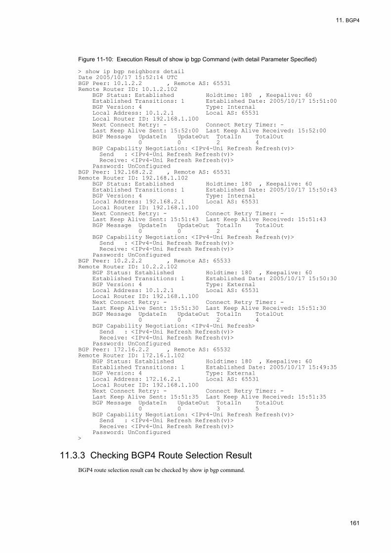
11. BGP4
Figure 11-10: Execution Result of show ip bgp Command (with detail Parameter Specified)
> show ip bgp neighbors detailDate 2005/10/17 15:52:14 UTCBGP Peer: 10.1.2.2 , Remote AS: 65531Remote Router ID: 10.1.2.102 BGP Status: Established Holdtime: 180 , Keepalive: 60 Established Transitions: 1 Established Date: 2005/10/17 15:51:00 BGP Version: 4 Type: Internal Local Address: 10.1.2.1 Local AS: 65531 Local Router ID: 192.168.1.100 Next Connect Retry: - Connect Retry Timer: - Last Keep Alive Sent: 15:52:00 Last Keep Alive Received: 15:52:00 BGP Message UpdateIn UpdateOut TotalIn TotalOut 0 0 2 4 BGP Capability Negotiation: <IPv4-Uni Refresh Refresh(v)> Send : <IPv4-Uni Refresh Refresh(v)> Receive: <IPv4-Uni Refresh Refresh(v)> Password: UnConfiguredBGP Peer: 192.168.2.2 , Remote AS: 65531Remote Router ID: 192.168.1.102 BGP Status: Established Holdtime: 180 , Keepalive: 60 Established Transitions: 1 Established Date: 2005/10/17 15:50:43 BGP Version: 4 Type: Internal Local Address: 192.168.2.1 Local AS: 65531 Local Router ID: 192.168.1.100 Next Connect Retry: - Connect Retry Timer: - Last Keep Alive Sent: 15:51:43 Last Keep Alive Received: 15:51:43 BGP Message UpdateIn UpdateOut TotalIn TotalOut 0 0 2 4 BGP Capability Negotiation: <IPv4-Uni Refresh Refresh(v)> Send : <IPv4-Uni Refresh Refresh(v)> Receive: <IPv4-Uni Refresh Refresh(v)> Password: UnConfiguredBGP Peer: 10.2.2.2 , Remote AS: 65533Remote Router ID: 10.2.2.102 BGP Status: Established Holdtime: 180 , Keepalive: 60 Established Transitions: 1 Established Date: 2005/10/17 15:50:30 BGP Version: 4 Type: External Local Address: 10.1.2.1 Local AS: 65531 Local Router ID: 192.168.1.100 Next Connect Retry: - Connect Retry Timer: - Last Keep Alive Sent: 15:51:30 Last Keep Alive Received: 15:51:30 BGP Message UpdateIn UpdateOut TotalIn TotalOut 0 0 2 4 BGP Capability Negotiation: <IPv4-Uni Refresh> Send : <IPv4-Uni Refresh Refresh(v)> Receive: <IPv4-Uni Refresh Refresh(v)> Password: UnConfiguredBGP Peer: 172.16.2.2 , Remote AS: 65532Remote Router ID: 172.16.1.102 BGP Status: Established Holdtime: 180 , Keepalive: 60 Established Transitions: 1 Established Date: 2005/10/17 15:49:35 BGP Version: 4 Type: External Local Address: 172.16.2.1 Local AS: 65531 Local Router ID: 192.168.1.100 Next Connect Retry: - Connect Retry Timer: - Last Keep Alive Sent: 15:51:35 Last Keep Alive Received: 15:51:35 BGP Message UpdateIn UpdateOut TotalIn TotalOut 0 0 3 5 BGP Capability Negotiation: <IPv4-Uni Refresh Refresh(v)> Send : <IPv4-Uni Refresh Refresh(v)> Receive: <IPv4-Uni Refresh Refresh(v)> Password: UnConfigured>
11.3.3 Checking BGP4 Route Selection ResultBGP4 route selection result can be checked by show ip bgp command.
161

11. BGP4
Figure 11-11: Execution Result of show ip bgp Command
> show ip bgpDate 2005/10/18 22:44:23 UTCLocal AS: 65531, Local Router ID: 192.168.1.100Status Codes: * valid, > activeOrigin Codes: i - IGP, e - EGP, ? - incomplete Network Next Hop MED LocalPref Weight Path*> 10.10/16 172.16.2.2 - 120 20 65532 65528 i ...1* 10.10/16 10.2.2.2 - 80 20 65533 65533 65529 i ...2* 10.10/16 10.1.2.2 - 80 10 65534 i ...3*> 10.20/16 172.16.2.2 - 80 20 65532 65528 i ...4* 10.20/16 10.2.2.2 - 80 20 65533 65533 65529 i ...5*> 172.20/16 192.168.2.2 - 100 10 65530 i ...6* 172.20/16 10.1.2.2 - 100 10 65534 65530 ? ...7*> 172.30/16 10.1.2.2 - 100 10 65534 i ...8* 172.30/16 192.168.2.2 100 100 10 65530 i ...9*> 192.168.10/24 10.1.2.2 - 100 10 65534 i ...10* 192.168.10/24 192.168.2.2 - 100 10 65530 i ...11*> 192.169.10/24 192.168.2.2 - 100 10 i ...12*> 192.169.20/24 192.168.2.2 - 100 10 i ...13
1 to 3: Selection of route 10.10/161 and 2 are given priority by comparing the weight value and then 1 is given priority by comparing the LOCAL_PREF attribute.
4 and 5: Route 10.20/16 selected4 is selected by comparing the AS_PATH attribute length.
6 and 7: Route 172.20/16 selected6 is selected by comparing the ORIGIN attribute.
8 and 9: Route 172.30/16 selected8 is selected based on comparison of MED attributes.
10 and 11: Route 192.168.10/24 selected10 is selected by comparing the remote BGP identifier.
12 and 13: Routes 192.169.10/24 and 192.169.20/24 selected12 and 13 are selected because there is no other route with the same destination.
11.3.4 Checking BGP4 Route Advertising ContentWhen checking the path attribute of advertised BGP4 route, use operation command show ip bgp with advertised-routes parameter specified.
Figure 11-12: Execution Result of show ip bgp Command (with advertised-routes Parameter Specified)
> show ip bgp advertised-routesDate 2005/10/18 22:44:54 UTCBGP Peer: 10.2.2.2 , Remote AS: 65533Local AS: 65531, Local Router ID: 192.168.1.100Origin Codes: i - IGP, e - EGP, ? - incompleteNetwork Next Hop MED LocalPref Path192.169.10/24 192.168.2.2 120 - 65531 i ...1192.169.20/24 192.168.2.2 100 - 65531 iBGP Peer: 172.16.2.2 , Remote AS: 65532Local AS: 65531, Local Router ID: 192.168.1.100Origin Codes: i - IGP, e - EGP, ? - incompleteNetwork Next Hop MED LocalPref Path192.169.10/24 192.168.2.2 120 - 65531 i ...2192.169.20/24 192.168.2.2 100 - 65531 i
1 and 2: MED attribute (value: 120) is set in advertised route.
162
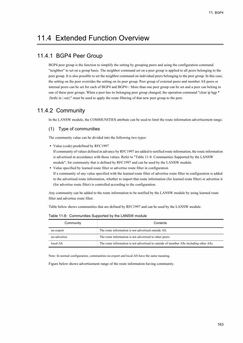
11. BGP4
11.4 Extended Function Overview
11.4.1 BGP4 Peer GroupBGP4 peer group is the function to simplify the setting by grouping peers and using the configuration command "neighbor" to set on a group basis. The neighbor command set on a peer group is applied to all peers belonging to the peer group. It is also possible to set the neighbor command on individual peers belonging to the peer group. In this case, the setting on the peer overrides the setting on its peer group. Peer group of external peers and member AS peers or internal peers can be set for each of BGP4 and BGP4+. More than one peer group can be set and a peer can belong to one of these peer groups. When a peer has its belonging peer group changed, the operation command "clear ip bgp * {both| in | out}" must be used to apply the route filtering of that new peer group to the peer.
11.4.2 CommunityIn the LANSW module, the COMMUNITIES attribute can be used to limit the route information advertisement range.
(1) Type of communities
The community value can be divided into the following two types:
• Value (code) predefined by RFC1997If community of values defined in advance by RFC1997 are added to notified route information, the route information is advertised in accordance with those values. Refer to "Table 11-8: Communities Supported by the LANSW module", for community that is defined by RFC1997 and can be used by the LANSW module.
• Value specified by learned route filter or advertise route filter in configurationIf a community of any value specified with the learned route filter of advertise route filter in configuration is added to the advertised route information, whether to import that route information (for learned route filter) or advertise it (for advertise route filter) is controlled according to the configuration.
Any community can be added to the route information to be notified by the LANSW module by using learned route filter and advertise route filter.
Table below shows communities that are defined by RFC1997 and can be used by the LANSW module.
Table 11-8: Communities Supported by the LANSW module
Note: In normal configuration, communities no-export and local-AS have the same meaning.
Figure below shows advertisement range of the route information having community.
Community Contents
no-export The route information is not advertised outside AS.
no-advertise The route information is not advertised to other peers.
local-AS The route information is not advertised to outside of member ASs including other ASs.
163

11. BGP4
Figure 11-13: Advertisement Scope of Route Information with COMMUNITIES Attribute
(2) Example of using learned route filtering and COMMUNITIES attribute
An example of using a learned route filtering and COMMUNITIES attribute is shown in the figure below.
Figure 11-14: Example of Using Learned Route Filtering and COMMUNITIES Attribute
Assume that 2 routers (Router A and Router B) are connected to a single external AS. To distribute the traffic load to outside AS, the traffic from Router C is relayed outside the AS via Router A, and the traffic from System D is relayed outside the AS via Router B. In this case, load distribution is possible by defining the following attributes to each router:
1. Add the Community a to the route advertised from Router A to an internal peer.(This can be specified by the advertise route filter.)
2. Add the Community b to the route advertised from Router B to an internal peer.(This can be specified by the advertise route filter.)
3. On Router C, if the received route information has Community a, set the LOCAL-PREF value of the corresponding route information to x (x < y) and if the received route information has Community b, set the LOCAL-PREF value of the corresponding route information to y (x < y). In other words, give priority to the route information advertised from Router A.(This can be specified by the learned route filter.)
4. On system D, if the received route information has Community a, set the LOCAL-PREF value of the corresponding
164

11. BGP4
route information to y (x < y) and if the received route information has Community b, set the LOCAL-PREF value of the corresponding route information to y (x <y). In other words, give priority to the route information advertised from Router B.(This can be specified by the learned route filter.)
11.4.3 BGP4 MultipathBGP4 multipath implements the traffic distribution by generating multiple routes (paths) to one destination network. The concept of multipath generation of BGP4 route on the LANSW module is described below.
(1) BGP4 multipath by IGP multipath
The next-hop solution of BGP4 routes is executed on the basis of the IGP routes. When the multipath of the IGP route corresponding to the next-hop attribute value of the BGP4 route is implemented at the next-hop resolution, the BGP4 route is also made multipath. The figure below shows the concept of multipath generation.
Figure 11-15: Concept of BGP4 Multipath by IGP Multipath
Assume that there are two physical interfaces between each router. For peering between each router, the addresses given to the system are used. In the LANSW module, the address can be assigned to the System itself by using configuration command ip address with loopback interface specified. Also, the system address can be specified for peering local address by using configuration command neighbor update-source. When using configuration command neighbor update-source for the external peer and member AS peer, specify configuration command neighbor ebgp-multihop together.
The BGP4 route (destination: Network W, NextHop: A) advertised from AS100 to System 1 refers to the IGP route at the next-hop solution. Since the gateway of the IGP route to NextHop: A is "a" and "b", the gateway of the BGP4 route is also "a" and "b". In the same way, the gateway of the BGP4 route (destination: Network W, NextHop: B) advertised from System 1 to System 2 is "c" and "d" because the gateway of the BGP4 route is "c" and "d".
Note on BGP4 multipath by IGP multipathThe multipath of the BGP routes is available to static routes and OSPF routes. Refer to "7.1 Static Routing Overview (IPv4)" for static route multipath concept and "9.1.7 Equal Cost Multipath" for OSPF route multipath concept.
(2) BGP4 multipath learned from multiple peers
In the LANSW module, the tie-break state BGP4 routes to the same destination, learned from multiple peers which are connected to the same neighboring AS, can be made multipath by using configuration command maximum-paths. Moreover, BGP4 route learned from different adjacent AS can be made multipath by specifying the all-as parameter for the configuration command maximum-paths. The following table shows the tiebreak condition.
165
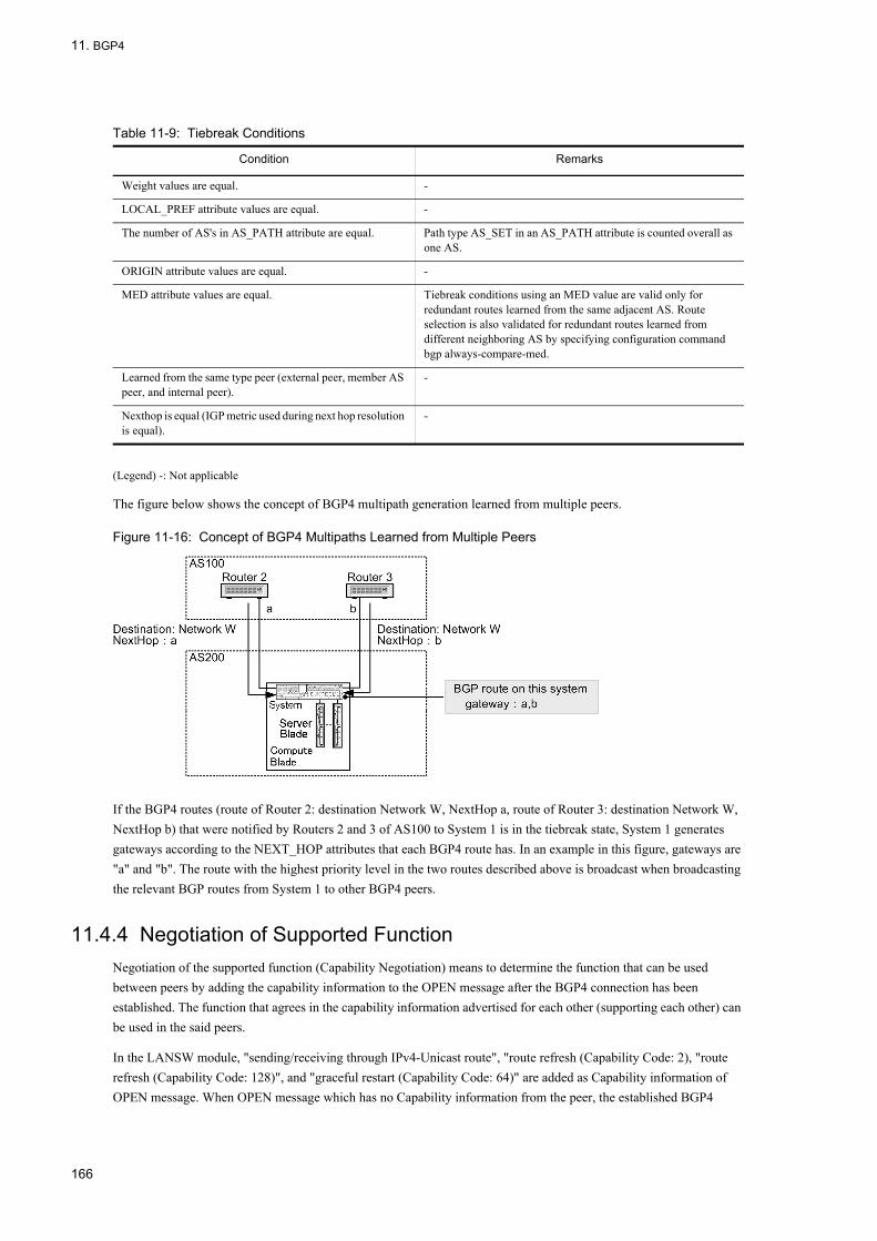
11. BGP4
Table 11-9: Tiebreak Conditions
(Legend) -: Not applicable
The figure below shows the concept of BGP4 multipath generation learned from multiple peers.
Figure 11-16: Concept of BGP4 Multipaths Learned from Multiple Peers
If the BGP4 routes (route of Router 2: destination Network W, NextHop a, route of Router 3: destination Network W, NextHop b) that were notified by Routers 2 and 3 of AS100 to System 1 is in the tiebreak state, System 1 generates gateways according to the NEXT_HOP attributes that each BGP4 route has. In an example in this figure, gateways are "a" and "b". The route with the highest priority level in the two routes described above is broadcast when broadcasting the relevant BGP routes from System 1 to other BGP4 peers.
11.4.4 Negotiation of Supported FunctionNegotiation of the supported function (Capability Negotiation) means to determine the function that can be used between peers by adding the capability information to the OPEN message after the BGP4 connection has been established. The function that agrees in the capability information advertised for each other (supporting each other) can be used in the said peers.
In the LANSW module, "sending/receiving through IPv4-Unicast route", "route refresh (Capability Code: 2), "route refresh (Capability Code: 128)", and "graceful restart (Capability Code: 64)" are added as Capability information of OPEN message. When OPEN message which has no Capability information from the peer, the established BGP4
Condition Remarks
Weight values are equal. -
LOCAL_PREF attribute values are equal. -
The number of AS's in AS_PATH attribute are equal. Path type AS_SET in an AS_PATH attribute is counted overall as one AS.
ORIGIN attribute values are equal. -
MED attribute values are equal. Tiebreak conditions using an MED value are valid only for redundant routes learned from the same adjacent AS. Route selection is also validated for redundant routes learned from different neighboring AS by specifying configuration command bgp always-compare-med.
Learned from the same type peer (external peer, member AS peer, and internal peer).
-
Nexthop is equal (IGP metric used during next hop resolution is equal).
-
166

11. BGP4
connection will only perform the "sending/receiving of the IPv4-Unicast route".
For the negotiable function, see the table below.
Table 11-10: Negotiable Functions
* If either negotiation is established, route refresh function of IPv4-route can be used.
Also, the following figure shows the concept of negotiation operation.
Figure 11-17: Operational Concept of Negotiation
11.4.5 Route RefreshRoute refresh is a function that operates in BGP4 based on the differential UPDATE (which advertises only the route that occurs with change), to force to re-advertise a route that has already been advertised.
The route refresh function operates to re-advertise the route from the local system, as well as re-advertise the route from the mate system. In addition, it is possible to select the type of route to re-advertise. This function is executed with the clear ip bgp command.
The following table shows the route refresh functions.
Function Name OPEN Message Capability Information Contents
Transmission and reception of the IPv4 route
Capability Code : 1Capability Value AFI : 1Capability Value SAFI : 1
Transmits and receives the IPv4-Unicast route between subject peers.
Route refresh Capability Code : 2Capability Value AFI : 1*
Uses the route refresh function of IPv4-route.
Capability Code : 128Capability Value AFI : 1*
Graceful restart Capability Code : 64Capability Value AFI : 1Capability Value SAFI : 1
Uses the graceful restart function.
167

11. BGP4
Table 11-11: Route Refresh Function
The following figures shows the operating concept of the route refresh function.
Figure 11-18: Operational Concept of Route Refresh Function
(1) Note on employing route refresh
For retransmission of the route from the mate system side, both routers that have been peered must support the route refresh function. To enable the route refresh function, it must be decided by negotiation between the routers when establishing the BGP4 peer.
Also, if the inbound parameter is specified with the configuration command neighbor soft-reconfiguration, route refresh request for route re-advertisement from the mate system to local system is not performed because the route suppressed with the learned route filter is retained as invalid route.
The route refresh function of the LANSW module conforms to RFC2918. The route refresh Capability code used for negotiation is RFC2918 compliant code (value=2) and private code (value=128). In addition, a private Capability code (value=128 to 255) defined in RFC2434 may also be used by other vendors.
Pay attention when using a refresh function between the LANSW module and other systems.
11.4.6 TCP MD5 AuthenticationThe LANSW module conforms to RFC2385 (the BGP session protection based on TCP MD5 authentication). Using TCP MD5 authentication function guarantees that the TCP segment received by BGP4 connection was transmitted from the valid source (peer). TCP MD5 authentication can be specified for each peer. Specify authentication key using the configuration command neighbor password when applying TCP MD5 authentication to the BGP4 connection with the peer. The authentication key must coincide between the relevant peers. The BGP4 connection between the relevant
Function Type Route type Re-advertising Direction
Re-transmission of the IPv4-unicast route
IPv4 unicast route Re-advertises the route on the mate system peered from the local system side.
Re-reception of the IPv4-unicast route Specifies the local system to re-advertise the route from the peered mate system.
168
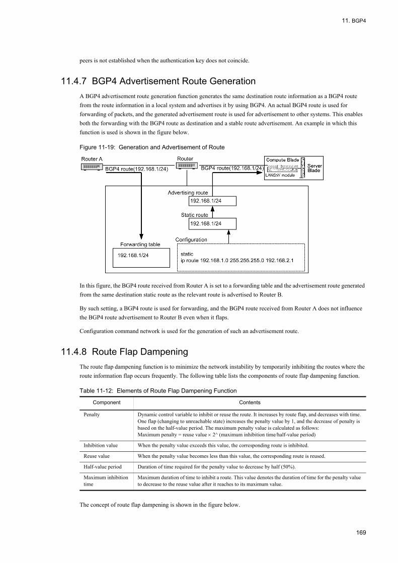
11. BGP4
peers is not established when the authentication key does not coincide.
11.4.7 BGP4 Advertisement Route GenerationA BGP4 advertisement route generation function generates the same destination route information as a BGP4 route from the route information in a local system and advertises it by using BGP4. An actual BGP4 route is used for forwarding of packets, and the generated advertisement route is used for advertisement to other systems. This enables both the forwarding with the BGP4 route as destination and a stable route advertisement. An example in which this function is used is shown in the figure below.
Figure 11-19: Generation and Advertisement of Route
In this figure, the BGP4 route received from Router A is set to a forwarding table and the advertisement route generated from the same destination static route as the relevant route is advertised to Router B.
By such setting, a BGP4 route is used for forwarding, and the BGP4 route received from Router A does not influence the BGP4 route advertisement to Router B even when it flaps.
Configuration command network is used for the generation of such an advertisement route.
11.4.8 Route Flap DampeningThe route flap dampening function is to minimize the network instability by temporarily inhibiting the routes where the route information flap occurs frequently. The following table lists the components of route flap dampening function.
Table 11-12: Elements of Route Flap Dampening Function
The concept of route flap dampening is shown in the figure below.
Component Contents
Penalty Dynamic control variable to inhibit or reuse the route. It increases by route flap, and decreases with time. One flap (changing to unreachable state) increases the penalty value by 1, and the decrease of penalty is based on the half-value period. The maximum penalty value is calculated as follows:Maximum penalty = reuse value × 2^ (maximum inhibition time/half-value period)
Inhibition value When the penalty value exceeds this value, the corresponding route is inhibited.
Reuse value When the penalty value becomes less than this value, the corresponding route is reused.
Half-value period Duration of time required for the penalty value to decrease by half (50%).
Maximum inhibition time
Maximum duration of time to inhibit a route. This value denotes the duration of time for the penalty value to decrease to the reuse value after it reaches to its maximum value.
169

11. BGP4
Figure 11-20: Operational Concept of Route Flap Dampening
11.4.9 Route ReflectionThe route reflection is a method to reduce the number of internal peers in AS. BGP4 does not distribute the route information distributed by an internal peer to any other internal peers. Therefore, internal peers must be logically formed in a full-meshed way among BGP speaker in AS. The route reflection loosens this restriction to reduce the number of internal peers by allowing the route information distributed by an internal peer to be redistributed to other internal peers.
(1) Concept and route information flow of the route reflection
The route reflection configures a cluster with a route reflector (RR) and its clients. A cluster can have more than one route reflector. Other BGP speakers in AS are called non-client.
When the route reflector receives the UPDATE message from a client in the cluster, it distributes the message to all non-clients and all clients (including the source client) in the cluster. The route reflector also distributes the UPDATE message from a non-client to all clients in the cluster. In this way, the internal peer from a client in the cluster to a non-client or the internal peer between the clients in the cluster are no longer necessary.
For the route information distributed from/to an external peer and member AS peer, the operation is the same as the normal distribution.
(2) When placing one route reflector in a cluster
The example below shows the route reflection with one route reflector in a cluster.
170
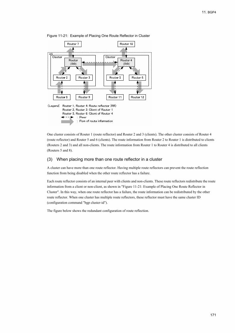
11. BGP4
Figure 11-21: Example of Placing One Route Reflector in Cluster
One cluster consists of Router 1 (route reflector) and Router 2 and 3 (clients). The other cluster consists of Router 4 (route reflector) and Router 5 and 6 (clients). The route information from Router 2 to Router 1 is distributed to clients (Routers 2 and 3) and all non-clients. The route information from Router 1 to Router 4 is distributed to all clients (Routers 5 and 8).
(3) When placing more than one route reflector in a cluster
A cluster can have more than one route reflector. Having multiple route reflectors can prevent the route reflection function from being disabled when the other route reflector has a failure.
Each route reflector consists of an internal peer with clients and non-clients. These route reflectors redistribute the route information from a client or non-client, as shown in "Figure 11-21: Example of Placing One Route Reflector in Cluster". In this way, when one route reflector has a failure, the route information can be redistributed by the other route reflector. When one cluster has multiple route reflectors, these reflector must have the same cluster ID (configuration command "bgp cluster-id").
The figure below shows the redundant configuration of route reflection.
171
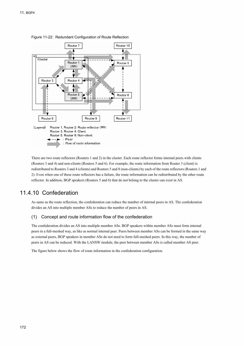
11. BGP4
Figure 11-22: Redundant Configuration of Route Reflection
There are two route reflectors (Routers 1 and 2) in the cluster. Each route reflector forms internal peers with clients (Routers 3 and 4) and non-clients (Routers 5 and 6). For example, the route information from Router 3 (client) is redistributed to Routers 3 and 4 (clients) and Routers 5 and 8 (non-clients) by each of the route reflectors (Routers 1 and 2). Even when one of these route reflectors has a failure, the route information can be redistributed by the other route reflector. In addition, BGP speakers (Routers 5 and 6) that do not belong to the cluster can exist in AS.
11.4.10 ConfederationAs same as the route reflection, the confederation can reduce the number of internal peers in AS. The confederation divides an AS into multiple member ASs to reduce the number of peers in AS.
(1) Concept and route information flow of the confederation
The confederation divides an AS into multiple member ASs. BGP speakers within member ASs must form internal peers in a full-meshed way, as like as normal internal peer. Peers between member ASs can be formed in the same way as external peers, BGP speakers in member ASs do not need to form full-meshed peers. In this way, the number of peers in AS can be reduced. With the LANSW module, the peer between member ASs is called member AS peer.
The figure below shows the flow of route information in the confederation configuration.
172

11. BGP4
Figure 11-23: Flow of Route Information in Confederation Configuration
Routers 1, 2 and 3 make up a member AS. Routers 4, 5 and 6 make up another member AS. The route information from Router 8 is distributed to other BGP speakers (Routers 1 and 3) in the member AS by Router 2. The route information distributed from Router 2 to Router 1 is distributed to other member AS (Router 4). Also, the route information from Router 1 to Router 4 is distributed to other BGP speaker (Routers 5 and 8) in the member AS. In this way, the route information is distributed to all BGP speakers in the AS.
(2) Route selection in the confederation configuration
The route selection in the confederation configuration partially differs from the normal configuration (non-confederation configuration) because the peer type (member AS peer) is added. In normal configuration, first the route learned from external peer is selected and then the route learned from internal peer is selected. In the confederation configuration, the route selection is made in the following order: route learned from external peer, route learned from member AS peer, and route learned form internal peer.
The table below shows the route selection priority in the confederation configuration.
Table 11-13: Route Selection Priority
*1The path type of the AS_PATH attributes, AS_SET is counted as one AS. Path type AS_CONFED_SET on the AS_PATH attribute is not included in the AS path length.
Precedence Contents
High↑
↓Low
Selects the route with the largest weight value.
Selects the route that has the largest LOCAL_PREF attribute value.
Selects the route that has the shortest number of ASs in AS_PATH attribute.*1
Selects using the ORIGIN attribute value in the order of IGP, EGP, and Incomplete.
Selects the route that has the smallest MED attribute value.*2
Selects the route learned from external peer, route learned from member AS peer, and then route learned from internal peer.
Selects the route that has the closest next-hop address value (the smallest metric value of IGP route used at next-hop solution.
Selects the route that has the smallest BGP identifier (router ID) at the other end.*3
Selects a route with a smaller learning source peer address.*3
173

11. BGP4
*2The route selection by MED value is effective only for the redundant route learned from the same neighboring AS. However, by specifying the configuration command bgp always-compare-med, it is also valid for redundant routes learned from different adjacent AS.
*3If the values of the remote BGP identifiers (router IDs) are different between the routes received from the external peer, route selection with the remote BGP identifier (router ID) and learning source peer address is not performed, but the already selected route is adopted. Route selection with the remote BGP identifier (router ID) is possible even if values of remote BGP identifiers (router IDs) are different between the routes received from the external peer by specifying configuration command "bgp bestpath compare-routerid".
(3) Handling of the BGP attribute in the confederation configuration
The BGP attribute in the confederation configuration is handled in the same way as in the normal configuration, however, some operation differs in the AS_PATH and COMMUNITIES attributes. The handling of the BGP attribute in member AS peers is as same as in internal peers.
(4) Handling of the AS_PATH attribute in the confederation configuration
In the confederation configuration, when the route information is distributed to member AS peers, the local member AS number is added to the path type AS_CONFED_SET of AS_PATH attribute. When the route information is distributed to other ASs (external peers), the path type AS_CONFED_SET is removed form the AS_PATH attribute, and the local AS number is added to the path type AS_SEQUENCE. Apart from these operation, the AS_PATH is handled in the same way as in the normal configuration.
The figure below shows the handling of AS_PATH attribute.
Figure 11-24: Handling of AS_PATH Attribute
When Route 1 distributes the route information from AS100, ASPATH: (AS_SEQUENCE) 100, to another member AS Router 2, it adds the local member AS number (65001) to the path type AS_CONFED_SET of the AS_PATH attribute. When Router 2 distributes the route information from Router 1, ASPATH: (AS_CONFED_SET) 65001 and (AS_SEQUENCE) 100 to AS300, it removes the path type AS_CONFED_SET from the AS_PATH attribute, and adds the local AS number (200) to the path type AS_SEQUENCE.
(5) Handling of the COMMUNITIES attribute in the confederation configuration
In the confederation configuration, the well-known communities defined in RFC1997 are handled as follows. Other communities are handled in the same way as in the normal configuration.
"Table 11-14: Well-known Communities Defined in RFC1997" lists the well-known communities defined in RFC1997.
174
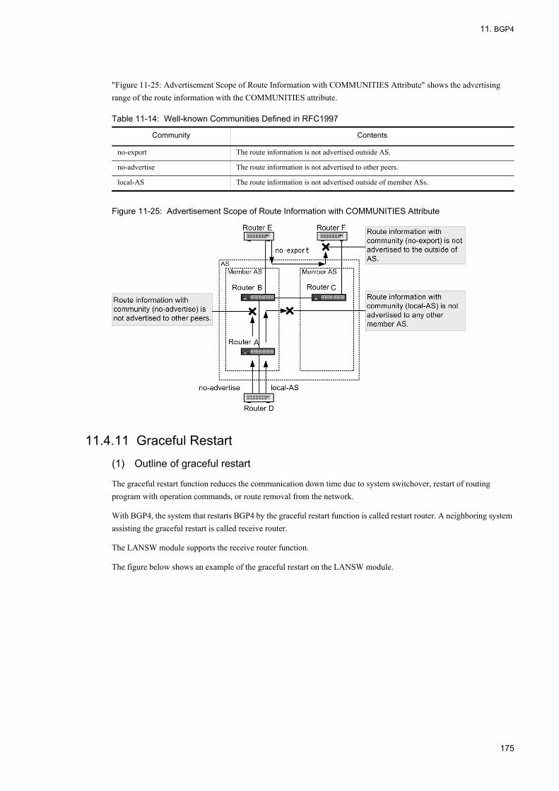
11. BGP4
"Figure 11-25: Advertisement Scope of Route Information with COMMUNITIES Attribute" shows the advertising range of the route information with the COMMUNITIES attribute.
Table 11-14: Well-known Communities Defined in RFC1997
Figure 11-25: Advertisement Scope of Route Information with COMMUNITIES Attribute
11.4.11 Graceful Restart
(1) Outline of graceful restart
The graceful restart function reduces the communication down time due to system switchover, restart of routing program with operation commands, or route removal from the network.
With BGP4, the system that restarts BGP4 by the graceful restart function is called restart router. A neighboring system assisting the graceful restart is called receive router.
The LANSW module supports the receive router function.
The figure below shows an example of the graceful restart on the LANSW module.
Community Contents
no-export The route information is not advertised outside AS.
no-advertise The route information is not advertised to other peers.
local-AS The route information is not advertised outside of member ASs.
175

11. BGP4
Figure 11-26: Example of Graceful Restart
Assume that the LANSW module of AS200 and Router A of AS100 establish a BGP connection with the interface addresses as peer addresses. Also, an internal peer BGP connection is established between Router A and Router B, and an external peer BGP connection is established between Router B and Router C. Assume that the graceful restart negotiation is successful on each BGP connection. When Router A performs graceful restart, the Router A which has the BGP connection to the LANSW module and Router B operate as receive routers to continue packet forwarding via Router A. In this way, end-to-end communication via Router A can be maintained.
The conditions for successful BGP4 graceful restart are shown below. If these conditions are not satisfied, normal restart is performed and communication is stopped.
• To operate the LANSW module as receive router, the configuration command "bgp graceful-restart mode" must be set.
• Graceful restart negotiation must be successful on the BGP connection between the system to perform graceful restart and the system to act as receive router.
(2) Graceful restart operation procedure
The figure below shows the operation sequence of BGP4 graceful restart.
176

11. BGP4
Figure 11-27: Graceful Restart Sequence
1. Preparation for graceful restart is made by negotiating the graceful restart function when establishing a BGP connection between the router that performs graceful restart and its neighboring router.
2. When the router performs graceful restart, the restart router operation starts.3. When BGP connection is interrupted, the neighboring router starts the receive router operation to maintain the route
information and continue packet forwarding.4. When BGP connection is reestablished, the route information is distributed first from the receive router to the restart
router.5. When learning of all protocols performing graceful restart is completed on the restart router, the route information
is distributed from the restart router to the receive router.6. Same as 5.7. Finally, the receive router discards old route information (among the route information learned from the restart
router) not received after BGP connection was reestablished.
(3) Receive router function
(a) Activation timing
The timing of activating the BGP4 receive router function on the LANSW module is as follows:
• The NOTIFICATION message is not received from the peer with which BGP connection is established, and disconnection of TCP session used by the connection is detected.
• New TCP session is established from the peer with which BGP connection has been established, and the OPEN message is received.
(b) Receive router function
The receive router monitors the maximum standby time until BGP connection is reestablished after the initiation of graceful restart according to the configuration command "bgp graceful-restart restart-time" setting (see (a) in "Figure 11-27: Graceful Restart Sequence"). If the BGP connection is not reestablished within this time, the receive router
177

11. BGP4
discards the route information learned form the restart router and stops packet forwarding via the restart router.
The restart-time value is notified to the peer when the graceful restart function is negotiated. The LANSW module uses the notified restart-time value for monitoring, when the value is smaller than the setting on the local system.
To specify the maximum duration of time for the receive router to maintain the route information learned before the restart router restarts, use the configuration command "bgp graceful-restart stalepath-time" (see (b) in "Figure 11-27: Graceful Restart Sequence").
In general, each parameter should be set as follows:
• Set the "stalepath-time" value greater than the duration of time required for the restart router to learn with all protocols.The duration of time required to learn with all protocols is the maximum time for the restart router to start the route distribution. Therefore, in the case of slowest route distribution, the restart router starts route distribution to the receive router after this duration of time elapses. To allow the receive router to delete old route information after the route is learned and the forwarding table is updated, set this parameter to a value app. 120 seconds greater than the duration of time required for the restart router to learn with all protocols. The value depends on the number of routes and the number of neighboring peers of the restart router.
(c) Case when helper function fails
Cases where BGP4 graceful restart fails are described below.
• The BGP connection is not reestablished even the specified restart-time elapses after the graceful restart function starts.
• The local system restarts while operating as receive router.• The peer system performing graceful restart cannot maintain the route information learned before the graceful restart
function starts.• After the graceful restart function starts, the reestablished BGP connection is disconnected again before the route
distribution from the restart router completes.• After the graceful restart function starts, the BGP connection is disconnected again because the number of routes
learned form the restart router exceeds the upper limit of the allowable number of BGP4 learned routes.
(4) Note on using the graceful restart function
1. Using with TCP MD5According to the protocol standard, when a BGP connection that supports graceful restart is established, the BGP connection that is being established is discarded and a new BGP connection is used if a new connection is requested from the peer. To avoid a security problem due to this operation, use the TCP MD5 authentication together.
2. Graceful restart in an IGP dependent environmentWhen the route information to peer address is exchanged by IGP using an internal peer connection which is not directly connected, or when the NEXT_HOP attribute of BGP route information is resolved by IGP route in the configuration that uses the route reflection function, set the graceful restart function also on that IGP.
11.4.12 BGP4 Learned Route RestrictionThe BGP4 learned route restriction is a function to limit the number of BGP4 routes to be learned from peers in order to prevent memory shortage due to a large volume of BGP4 route learning. It also prevents the excessive route learning from a particular peer, which disabling the system to learn routes from other peers. When this function is applied, an alarming operation message is output when the number of addresses learned from peers exceeds the specified threshold. When it exceeds the upper limit value, the peer is disconnected after an alarming operation message is output. Peer disconnected by this function is reconnected after a specified duration of time elapses, or by the operation command "clear ip bgp". The function can be set to output an alarming operation message but not disconnect the peer even when
178

11. BGP4
the number of learned routes exceeds the upper limit.
179
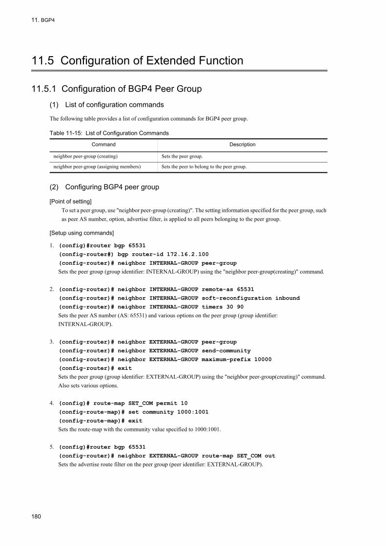
11. BGP4
11.5 Configuration of Extended Function
11.5.1 Configuration of BGP4 Peer Group
(1) List of configuration commands
The following table provides a list of configuration commands for BGP4 peer group.
Table 11-15: List of Configuration Commands
(2) Configuring BGP4 peer group
[Point of setting]To set a peer group, use "neighbor peer-group (creating)". The setting information specified for the peer group, such as peer AS number, option, advertise filter, is applied to all peers belonging to the peer group.
[Setup using commands]
1. (config)#router bgp 65531
(config-router#) bgp router-id 172.16.2.100
(config-router)# neighbor INTERNAL-GROUP peer-group
Sets the peer group (group identifier: INTERNAL-GROUP) using the "neighbor peer-group(creating)" command.
2. (config-router)# neighbor INTERNAL-GROUP remote-as 65531
(config-router)# neighbor INTERNAL-GROUP soft-reconfiguration inbound
(config-router)# neighbor INTERNAL-GROUP timers 30 90
Sets the peer AS number (AS: 65531) and various options on the peer group (group identifier: INTERNAL-GROUP).
3. (config-router)# neighbor EXTERNAL-GROUP peer-group
(config-router)# neighbor EXTERNAL-GROUP send-community
(config-router)# neighbor EXTERNAL-GROUP maximum-prefix 10000
(config-router)# exit
Sets the peer group (group identifier: EXTERNAL-GROUP) using the "neighbor peer-group(creating)" command. Also sets various options.
4. (config)# route-map SET_COM permit 10
(config-route-map)# set community 1000:1001
(config-route-map)# exit
Sets the route-map with the community value specified to 1000:1001.
5. (config)#router bgp 65531
(config-router)# neighbor EXTERNAL-GROUP route-map SET_COM out
Sets the advertise route filter on the peer group (peer identifier: EXTERNAL-GROUP).
Command Description
neighbor peer-group (creating) Sets the peer group.
neighbor peer-group (assigning members) Sets the peer to belong to the peer group.
180

11. BGP4
(3) Setting BGP4 peer to belong to the peer group
[Point of setting]Sets "neighbor peer-group(assigning members)" to make the peer belong to the peer group. The setting information specified to the peer group, such as peer AS number, option, advertise filter, is applied to that peer.
[Setup using commands]
1. (config-router)# neighbor 172.16.2.2 peer-group INTERNAL-GROUP
Makes the peer (remote address: 172.16.2.2) belong to the peer group (group identifier: INTERNAL-GROUP) using the "neighbor peer-group(assigning members)" command. For the AS number of peer, 65531 is used, which is specified for the peer group.
2. (config-router)# neighbor 172.17.3.3 peer-group INTERNAL-GROUP
Makes the peer (remote address: 172.17.3.3) belong to the peer group (group identifier: INTERNAL-GROUP) using the "neighbor peer-group(assigning members)" command. For the AS number of peer, 65531 is used, which is specified for the peer group.
3. (config-router)# neighbor 192.168.4.4 remote-as 65533
(config-router)# neighbor 192.168.4.4 peer-group EXTERNAL-GROUP
Sets the peer (remote address: 192.168.4.4) and makes it belong to the peer group (group identifier: EXTERNAL-GROUP). For the AS number of peer, 65533 is used, which is specified for the peer group.
4. (config-router)# neighbor 192.168.5.5 remote-as 65534
(config-router)# neighbor 192.168.5.5 peer-group EXTERNAL-GROUP
Sets the peer (remote address: 192.168.5.5) and makes it belong to the peer group (group identifier: EXTERNAL-GROUP). For the AS number of peer, 65534 is used, which is specified for the peer group.
11.5.2 Configuring Community
(1) List of configuration commands
The following table provides a list of community configuration commands.
Table 11-16: List of Configuration Commands
Note: See "12 Route Filtering (IPv4)" for the configuration command to configure the route filter.
Command Description
distribute-list in (BGP) Specifies the route filter to be used as BGP4 learned route filtering conditions.
distribute-list out (BGP) Specifies the route filter to be used as BGP4 advertise route filtering conditions.
neighbor route-map in (BGP) Specifies the route filter to be used as learned route filtering conditions for specific BGP4 peer only.
neighbor route-map out (BGP) Specifies the route filter to be used as advertise route filtering conditions for specific BGP4 peer only.
neighbor send-community Sets that COMMUNITIES attribute of the route to be advertised to the peer is not deleted.
redistribute (BGP) Specifies the protocol of the route to be advertised by BGP4.
181

11. BGP4
(2) Configuring community
[Point of setting]When adding COMMUNITIES attribute to the BGP4 route to be advertised, set configuration command neighbor send-community for the relevant peer.
[Setup using commands]
1. (config)#router bgp 65531
(config-router#) bgp router-id 192.168.1.100
(config-router)#neighbor 192.168.2.2 remote-as 65531
(config-router)#neighbor 172.16.2.2 remote-as 65532
(config-router)# neighbor 10.2.2.2 remote-as 65533
Sets BGP4 peers.
2. (config-router)# neighbor 172.16.2.2 send-community
(config-router)# neighbor 10.2.2.2 send-community
(config-router)# exit
Specifies that COMMUNITIES attribute is added to the BGP4 route to be advertised to the peer.
3. (config)# ip community-list 10 permit 1000:1002
(config)# ip community-list 20 permit 1000:1003
(config)# route-map SET_LOCPREF permit 10
(config-route-map)# match community 10
(config-route-map)# set local-preference 120
(config-route-map)# exit
(config)# route-map SET_LOCPREF permit 20
(config-route-map)# match community 20
(config-route-map)# set local-preference 80
(config-route-map)# exit
(config)# route-map SET_LOCPREF permit 30
(config-route-map)# exit
Sets the LOCAL_PREF attribute of route with COMMUNITIES attribute containing community value 1000:1002 to 120 and LOCAL_PREF attribute of route with COMMUNITIES attribute containing community value 1000:1003 to 80.
4. (config)# ip prefix-list MY_NET seq 10 permit 192.168.0.0/16 ge 16 le 30
(config)# route-map SET_COM permit 10
(config-route-map)# match ip address prefix-list MY_NET
(config-route-map)# set community 1000:1001
(config-route-map)# exit
Sets COMMUNITIES attribute which has community value 1000:1001 for the route destined to network 192.168.0.0/16 (mask length 16 to 30).
5. (config)#router bgp 65531
(config-router)# distribute-list route-map SET_LOCPREF in
(config-router)# distribute-list route-map SET_COM out
(config-router)# exit
Sets learned route filter and route advertisement filter of all peers.
182
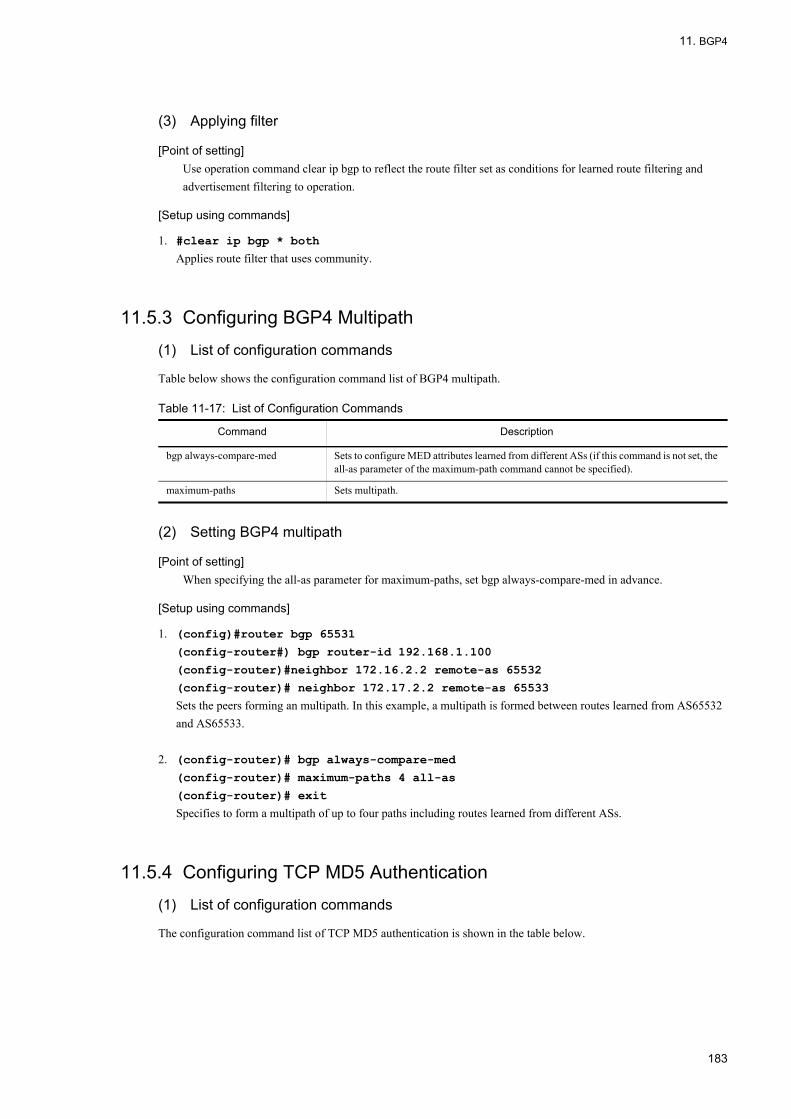
11. BGP4
(3) Applying filter
[Point of setting]Use operation command clear ip bgp to reflect the route filter set as conditions for learned route filtering and advertisement filtering to operation.
[Setup using commands]
1. #clear ip bgp * both
Applies route filter that uses community.
11.5.3 Configuring BGP4 Multipath
(1) List of configuration commands
Table below shows the configuration command list of BGP4 multipath.
Table 11-17: List of Configuration Commands
(2) Setting BGP4 multipath
[Point of setting]When specifying the all-as parameter for maximum-paths, set bgp always-compare-med in advance.
[Setup using commands]
1. (config)#router bgp 65531
(config-router#) bgp router-id 192.168.1.100
(config-router)#neighbor 172.16.2.2 remote-as 65532
(config-router)# neighbor 172.17.2.2 remote-as 65533
Sets the peers forming an multipath. In this example, a multipath is formed between routes learned from AS65532 and AS65533.
2. (config-router)# bgp always-compare-med
(config-router)# maximum-paths 4 all-as
(config-router)# exit
Specifies to form a multipath of up to four paths including routes learned from different ASs.
11.5.4 Configuring TCP MD5 Authentication
(1) List of configuration commands
The configuration command list of TCP MD5 authentication is shown in the table below.
Command Description
bgp always-compare-med Sets to configure MED attributes learned from different ASs (if this command is not set, the all-as parameter of the maximum-path command cannot be specified).
maximum-paths Sets multipath.
183

11. BGP4
Table 11-18: List of Configuration Commands
(2) Setting TCP MD5 authentication
[Point of setting]Use the configuration command neighbor password with authentication key to set TCP MD5 authentication.
[Setup using commands]
1. (config)#router bgp 65531
(config-router#) bgp router-id 192.168.1.100
(config-router)# neighbor 172.16.2.2 remote-as 65532
(config-router)#neighbor 192.168.2.2 remote-as 65531
Sets BGP4 peers.
2. (config-router)# neighbor 172.16.2.2 password "authmd5_65532"
(config-router)# exit
Sets TCP MD5 authentication which uses authentication key "authmd5_65532" for the peer with the remote address 172.16.2.2.
11.5.5 Configuring BGP4 Advertisement Route Generation
(1) List of configuration commands
Table below shows the configuration command list of BGP4 advertisement route generation.
Table 11-19: List of Configuration Commands
(2) Setting BGP4 advertisement route generation
[Point of setting]To generate BGP4 advertisement route, use configuration command network. Specify local with the route-map match route-type command to advertise route generated with the network command.
[Setup using commands]
1. (config)#router bgp 65531
(config-router#) bgp router-id 192.168.1.100
(config-router)#neighbor 172.16.2.2 remote-as 65532
(config-router)#neighbor 192.168.2.2 remote-as 65531
Sets BGP4 peers.
2. (config-router)# network 192.169.10.0/24 ge 16 le 30
(config-router)# network 173.16.0.0/16 le 24
(config-router)# exit
Generates the BGP4 advertisement route of 192.169.10.0/24 when the route with mask length 16 to 30, which
Command Description
neighbor password Sets to apply TCP MD5 authentication for connection with peer.
Command Description
network Sets generation of BGP4 advertisement route.
184

11. BGP4
corresponds to 192.169.10.0 prefix, exists in the routing table. Likewise, the command generates the BGP4 advertisement route of 173.16.0.0/16 when the route with mask length 16 to 24, which corresponds to 173.16.0.0 prefix, exists in the routing table.
3. (config)# route-map ADV_NET permit 10
(config-route-map)# match route-type local
(config-route-map)# exit
Specifies the generated BGP4 advertisement route.
4. (config)#router bgp 65531
(config-router#) neighbor 172.16.2.2 route-map ADV_NET out
(config-router)# exit
Specifies that the generated BGP4 advertisement route is advertised to the peer with the remote address 172.16.2.2.
(3) Applying filter
[Point of setting]To advertise the generated BGP4 advertisement route, use operation command clear ip bgp to reflect the filter to operation.
[Setup using commands]
1. #clear ip bgp * out
Reflects the route filter using BGP4 advertisement route to operation.
11.5.6 Configuring Route Flap Dampening
(1) List of configuration commands
The following table lists the configuration commands for route flap dampening.
Table 11-20: List of Configuration Commands
(2) Setting the route flap dampening
[Point of setting]To apply the route flap dampening to BGP4 routes, set the "bgp dampening" command in config-router mode.
[Setup using commands]
1. (config)#router bgp 65531
(config-router#) bgp router-id 192.168.1.100
(config-router)#neighbor 172.16.2.2 remote-as 65532
(config-router)# neighbor 172.17.2.2 remote-as 65533
Sets BGP4 peers.
2. (config-router)# bgp dampening
Applies the route flap dampening.
Command Description
bgp dampening Inhibits the route with flap temporarily to reduce the influence by route flap.
185

11. BGP4
11.5.7 Configuring Route ReflectionThe explanation of the configuration is provided based on the example shown in the figure below.
Figure 11-28: Configuration Example of Route Reflection
(1) List of configuration commands
The following table lists the configuration commands for the route reflection.
Table 11-21: List of Configuration Commands
(2) Setting the route reflection
[Point of setting]The setting is not required as the configuration command "bgp client-to-client reflection" is enabled by default. To disable the BGP4 route reflection between the route reflector clients, specify "no bgp client-to-client reflection" command in config-router mode.
[Setup using commands]
1. (config)#router bgp 65531
(config-router#) bgp router-id 192.168.1.100
(config-router)#neighbor 172.16.2.2 remote-as 65532
(config-router)# neighbor 192.168.2.2 remote-as 65531
Command Description
bgp client-to-client reflection Specifies to reflect the BGP4 routes between the route reflector clients.
bgp cluster-id Specifies the cluster ID to be used for route reflection.
bgp router-id Specifies an ID used as the cluster ID of router reflection when bgp cluster-id is not specified.
neighbor route-reflector-client Specifies the route reflector client.
neighbor always-nexthop-self Specifies to force to overwrite the NEXT-HOP attribute of the route advertised to internal peer to the local side address used for peering with internal peer (including the case of route reflection).
186

11. BGP4
(config-router)# neighbor 192.168.3.2 remote-as 65531
(config-router)# neighbor 192.168.4.2 remote-as 65531
(config-router)# neighbor 192.168.5.2 remote-as 65531
Sets the BGP4 peer by specifying router 1 as external peer and routers 2 to 5 as internal peers.
2. (config-router#) bgp cluster-id 10.1.2.1
Sets the cluster ID.
3. (config-router)# neighbor 192.168.2.2 route-reflector-client
(config-router)# neighbor 192.168.3.2 route-reflector-client
(config-router)# neighbor 192.168.4.2 route-reflector-client
Specifies routes 2 to 4 as route reflector clients.
11.5.8 Configuring ConfederationThe explanation of the configuration is provided based on the example shown in the figure below.
Figure 11-29: Configuration Example of Confederation
(1) List of configuration commands
The following table lists the configuration commands for confederation.
Table 11-22: List of Configuration Commands
(2) Setting the confederation
[Point of setting]Specify the local member AS number with "router bgp", and set the "bgp confederation peers" on other member
Command Description
bgp confederation identifier Specifies the local confederation AS number when confederation is configured.
bgp confederation peers Specifies the member AS number to connect when confederation is configured.
neighbor remote-as Sets BGP4/BGP4+ peer. Specifies the local member AS number to connect when confederation is configured.
187

11. BGP4
AS numbers to connect in config-router mode.
[Setup using commands]
1. (config)#router bgp 64512
Specifies the local member AS number (64512).
2. (config-router#) bgp router-id 192.168.1.100
Specifies the router ID.
3. (config-router)# bgp confederation identifier 65531
Specifies the local confederation AS number (65531).
4. (config-router)# bgp confederation peers 64513 64514
Specifies other member AS numbers (64513, 64514) to connect.
5. (config-router)#neighbor 172.16.2.2 remote-as 65532
(config-router)# neighbor 192.168.2.2 remote-as 64512
(config-router)# neighbor 192.168.3.2 remote-as 64512
(config-router)# neighbor 192.168.4.2 remote-as 64513
(config-router)# neighbor 192.168.5.2 remote-as 64514
Sets the BGP4 peer by specifying router 1 as external peer, routers 2 and 3 as internal peers, and routers 4 and 5 as member AS peers.
11.5.9 Configuring Graceful Restart
(1) List of configuration commands
The graceful restart configuration command list is shown in the table below.
Table 11-23: List of Configuration Commands
(2) Setting the graceful restart
[Point of setting]To use the graceful restart function, set the "bgp graceful-restart mode" command in config-router mode. When "bgp graceful-restart restart-time" command and "bgp graceful-restart stalepath-time" command must be set, set them after setting the "bgp graceful-restart mode" command.
[Setup using commands]
1. (config)#router bgp 65531
(config-router#) bgp router-id 192.168.1.100
(config-router)# neighbor 172.16.2.2 remote-as 65532
(config-router)# neighbor 192.168.2.2 remote-as 65531
Command Description
bgp graceful-restart mode Specifies the graceful restart function to be used.
bgp graceful-restart restart-time Specifies the maximum duration of time to reconnect the peer after the neighboring router starts the graceful restart.
bgp graceful-restart stalepath-time Specifies the maximum duration of time to retain the previous route after the neighboring router starts the graceful restart.
188

11. BGP4
Sets BGP4 peers.
2. (config-router)# bgp graceful-restart mode receive
Specifies the graceful restart receive router function to be used.
11.5.10 Configuring BGP4 Learned Route Restriction
(1) List of configuration commands
The following table provides a list of configuration commands for BGP4 learned route restriction.
Table 11-24: List of Configuration Commands
(2) Setting the restriction on the number of BGP4 learned routes
[Point of setting]To apply the restriction on the number of BGP4+ learned routes to the peer, set the "neighbor maximum-prefix" command.
[Setup using commands]
1. (config)#router bgp 65531
(config-router#) bgp router-id 192.168.1.100
(config-router)#neighbor 172.16.2.2 remote-as 65532
(config-router)# neighbor 192.168.2.2 remote-as 65531
Sets BGP4 peers.
2. (config-router)# neighbor 172.16.2.2 maximum-prefix 10000 80 restart 60
Sets the upper limit to 10000 for the number of routes to be learned form the external peer (remote address: 172.16.2.2), the alarming operation message output threshold to 80%, and the restart time to 60 minutes for reconnecting the disconnected peer after it exceeds the upper limit.
3. (config-router)# neighbor 192.168.2.2 maximum-prefix 1000 warning-only
Sets the upper limit to 1000 for the number of routes to be learned form the internal peer (remote address: 172.16.2.2) and specifies not to disconnect the peer even if it exceeds the upper limit.
Command Description
neighbor maximum-prefix Limits the number of routes to be learned from the corresponding peer.
189

11. BGP4
11.6 Operation of Extended Function
11.6.1 Checking BGP4 Peer Group
(1) List of operation commands
Table below shows the operation command list of BGP4 peer group.
Table 11-25: List of Operation Commands
(2) Checking BGP4 peer group
To check the peering information on the peers belonging to the peer group, use the "show ip bgp" command with the "peer-group" parameter specified.
Figure 11-30: Execution Result of show ip bgp Command (with peer-group Parameter Specified)
>show ip bgp peer-group INTERNAL-GROUPDate 2006/07/17 18:40:00 UTCLocal AS: 65531, Local Router ID: 172.16.2.100BGP Peer AS Received Sent Up/Down Status172.16.2.2 65531 36 42 06/07/16 18:42:26 Established172.16.3.3 65531 51 63 06/07/16 12:42:31 Established
(3) Checking peers belonging to the BGP4 peer group
To display the information on the peers belonging to the peer group, use the "show ip bgp" command with "neighbors", "peer-group", and "detail" parameters specified.
Figure 11-31: Execution Result of show ip bgp Command (with neighbors and peer-group Parameters Specified)
>show ip bgp neighbors peer-group EXTERNAL-GROUPDate 2006/07/17 18:45:09 UTCPeer Address Peer AS Local Address Local AS Type Status192.168.4.4 65533 192.168.4.214 65531 External Established192.168.5.5 65534 192.168.5.189 65531 External Active
(4) Checking BGP4 peer group to which the peer belongs
To check the peer group to which the peer belongs, use the "show ip bgp" command with "neighbors", "<Peer Address>", and "<Host name>" parameters specified.
Command Description
show ip bgp Displays BGP4 protocol information.
190

11. BGP4
Figure 11-32: Execution Result of show ip bgp Command (with neighbors and <Peer Address> Parameters Specified)
>show ip bgp neighbors 172.16.2.2Date 2006/07/17 18:45:09 UTCBGP Peer: 172.16.2.2, Remote AS: 65531Remote Router ID: 172.16.2.20, Peer Group: INTERNAL-GROUP ...1 BGP Status:Established HoldTime: 90 , Keepalive: 30 Established Transitions: 1 Established Date: 2006/07/16 18:42:26 BGP Version: 4 Type: Internal Local Address: 172.16.2.214, Local AS: 65531 Local Router ID: 172.16.2.100 Next Connect Retry:-, Connect Retry Timer: - Last Keep Alive Sent: 18:42:20, Last Keep Alive Received: 18:42:20 BGP Message UpdateIn UpdateOut TotalIn TotalOut 12 14 36 42 BGP Capability Negotiation: <IPv4-Uni Refresh Refresh(v)>> Send : <IPv4-Uni Refresh Refresh(v)> Receive: <IPv4-Uni Refresh Refresh(v)>> Password : UnConfigured
1. The peer belongs to the INTERNAL-GROUP peer group.
11.6.2 Checking Community
(1) List of operation commands
The following table provides a list of community operation commands.
Table 11-26: List of Operation Commands
(2) Displaying the community of learned route
To display the route having a specific community, set community parameter in show ip bgp command.
Figure 11-33: Execution Result of show ip bgp Command (with community Parameter Specified)
> show ip bgp community 1000:1002Date 2005/10/20 21:07:32 UTCLocal AS: 65531, Local Router ID: 192.168.1.100Status Codes: d dampened, * valid, > active, S StaleOrigin Codes: i - IGP, e - EGP, ? - incompleteNetwork Next Hop MED LocalPref Path*> 10.10/16 172.16.2.2 0 - 65532 i*> 10.20/16 172.16.2.2 0 - 65532 i
To display the community of the route, use route parameter of show ip bgp command.
Figure 11-34: Execution Result of show ip bgp Command (with route Parameter Specified)
> show ip bgp route 10.10/16Date 2005/10/20 21:09:12 UTCBGP Peer: 172.16.2.2 , Remote AS: 65532Local AS: 65531, Local Router ID: 192.168.1.100Status Codes: * valid, > activeRoute 10.10/16*> Next Hop 172.16.2.2 MED: -, LocalPref: 100, Weight: 0, Type: External route Origin: IGP, IGP Metric: 0 Path: 65532 Communities: 1000:1002
Command Description
show ip route Displays the route information held in the routing table.
show ip bgp Displays BGP4 protocol information.
191

11. BGP4
(3) Displaying the learned route filtering result
To display the result of learned route filtering, set COMMUNITIES attribute in operation command show ip bgp.
Figure 11-35: Execution Result of show ip bgp Command
> show ip bgpDate 2005/10/20 21:10:09 UTCLocal AS: 65531, Local Router ID: 192.168.1.100Status Codes: * valid, > activeOrigin Codes: i - IGP, e - EGP, ? - incomplete Network Next Hop MED LocalPref Weight Path*> 10.10/16 172.16.2.2 - 120 0 65532 i* 10.10/16 10.2.2.2 - 80 0 65533 i*> 10.20/16 172.16.2.2 - 120 0 65532 i* 10.20/16 10.2.2.2 - 80 0 65533 i*> 192.169.10/24 192.168.2.2 - 100 0 i*> 192.169.20/24 192.168.2.2 - 100 0 i
(4) Displaying the community of advertisement route
To display the COMMUNITIES attribute of advertised BGP4 route, set advertised-routes parameter of operation command show ip bgp.
Figure 11-36: Execution Result of show ip bgp Command (with advertised-routes Parameter Specified)
> show ip bgp advertised-routes 192.169.10/24Date 2005/10/20 21:10:25 UTCBGP Peer: 172.16.2.2 , Remote AS: 65532Local AS: 65531, Local Router ID: 192.168.1.100Route 192.169.10/24*> Next Hop 192.168.2.2 MED: -, LocalPref: -, Type: Internal route Origin: IGP Path: 65531 Next Hop Attribute: 172.16.2.1 Communities: 1000:1001 BGP Peer: 10.2.2.2 , Remote AS: 65533Local AS: 65531, Local Router ID: 192.168.1.100Route 192.169.10/24*> Next Hop 192.168.2.2 MED: -, LocalPref: -, Type: Internal route Origin: IGP Path: 65531 Next Hop Attribute: 10.1.2.1 Communities: 1000:1001
11.6.3 Checking BGP4 Multipath
(1) List of operation commands
The following table provides a list of multipath operation commands.
Table 11-27: List of Operation Commands
(2) Displaying BGP4 multipath
Settings of multipath are displayed by using operation command show ip route.
Command Description
show ip route Displays the routing table routes.
show ip entry Displays detailed information on specific IPv4 unicast route.
show ip bgp Displays BGP4 protocol information.
192

11. BGP4
Figure 11-37: Execution Result of show ip route Command
> show ip routeDate 2005/10/20 21:40:39 UTCTotal: 19 routesDestination Next Hop Interface Metric Protocol Age10.10/16 172.17.2.2 VLAN0006 -/- BGP 33m 31s ... 1 172.16.2.2 VLAN0005 - - -10.20/16 172.17.2.2 VLAN0006 -/- BGP 33m 31s ... 2 172.16.2.2 VLAN0005 - - -127/8 ---- loopback0 0/0 Connected 42m 45s127.0.0.1/32 127.0.0.1 loopback0 0/0 Connected 42m 45s172.17/16 172.17.2.2 VLAN0006 0/0 Connected 42m 43s172.17.2.1/32 172.17.2.2 VLAN0006 0/0 Connected 42m 43s172.16/16 172.16.2.2 VLAN0005 0/0 Connected 42m 43s172.16.2.1/32 172.16.2.2 VLAN0005 0/0 Connected 42m 43s172.10/16 172.17.2.2 VLAN0006 -/- BGP 3s ... 3 172.16.2.2 VLAN0005 - - -172.20/16 172.17.2.2 VLAN0006 -/- BGP 3s ... 4 172.16.2.2 VLAN0005 - - -192.168.1.100/32 192.168.1.100 loopback0 0/0 Connected 42m 45s
1 to 4: Multipathed routes.
11.6.4 Checking Supported Function Negotiation
(1) List of operation commands
The following table provides a list of support function negotiation operation commands.
Table 11-28: List of Operation Commands
(2) Checking negotiation
Negotiation of the support function is displayed by using neighbors and detail parameters of operation command show ip bgp.
Command Description
show ip bgp Displays BGP4 protocol information.
193

11. BGP4
Figure 11-38: Result of Executing show ip bgp Command (with neighbors detail Parameter Specified)
> show ip bgp neighbor detailDate 2005/10/17 15:52:14 UTCBGP Peer: 10.1.2.2 , Remote AS: 65531Remote Router ID: 10.1.2.102 BGP Status: Established Holdtime: 180 , Keepalive: 60 Established Transitions: 1 Established Date: 2005/10/17 15:51:00 BGP Version: 4 Type: Internal Local Address: 10.1.2.1 Local AS: 65531 Local Router ID: 192.168.1.100 Next Connect Retry: - Connect Retry Timer: - Last Keep Alive Sent: 15:52:00 Last Keep Alive Received: 15:52:00 BGP Message UpdateIn UpdateOut TotalIn TotalOut 0 0 2 4 BGP Capability Negotiation: <IPv4-Uni Refresh Refresh(v)> ...1 Send : <IPv4-Uni Refresh Refresh(v)> Receive: <IPv4-Uni Refresh Refresh(v)> Password: UnConfiguredBGP Peer: 192.168.2.2 , Remote AS: 65531Remote Router ID: 192.168.1.102 BGP Status: Established Holdtime: 180 , Keepalive: 60 Established Transitions: 1 Established Date: 2005/10/17 15:50:43 BGP Version: 4 Type: Internal Local Address: 192.168.2.1 Local AS: 65531 Local Router ID: 192.168.1.100 Next Connect Retry: - Connect Retry Timer: - Last Keep Alive Sent: 15:51:43 Last Keep Alive Received: 15:51:43 BGP Message UpdateIn UpdateOut TotalIn TotalOut 0 0 2 4 BGP Capability Negotiation: <IPv4-Uni Refresh> ...2 Send : <IPv4-Uni Refresh Refresh(v)> Receive: <IPv4-Uni Refresh > Password: UnConfiguredBGP Peer: 10.2.2.2 , Remote AS: 65533Remote Router ID: 10.2.2.102 BGP Status: Established Holdtime: 180 , Keepalive: 60 Established Transitions: 1 Established Date: 2005/10/17 15:50:30 BGP Version: 4 Type: External Local Address: 10.1.2.1 Local AS: 65531 Local Router ID: 192.168.1.100 Next Connect Retry: - Connect Retry Timer: - Last Keep Alive Sent: 15:51:30 Last Keep Alive Received: 15:51:30 BGP Message UpdateIn UpdateOut TotalIn TotalOut 0 0 2 4 BGP Capability Negotiation: <IPv4-Uni> ...3 Send : <IPv4-Uni Refresh Refresh(v)> Receive: <IPv4-Uni> Password: UnConfiguredBGP Peer: 172.16.2.2 , Remote AS: 65532Remote Router ID: 172.16.1.102 BGP Status: Established Holdtime: 180 , Keepalive: 60 Established Transitions: 1 Established Date: 2005/10/17 15:49:35 BGP Version: 4 Type: External Local Address: 172.16.2.1 Local AS: 65531 Local Router ID: 192.168.1.100 Next Connect Retry: - Connect Retry Timer: - Last Keep Alive Sent: 15:51:35 Last Keep Alive Received: 15:51:35 BGP Message UpdateIn UpdateOut TotalIn TotalOut 0 0 3 5 BGP Capability Negotiation: <> ...4 Send : <IPv4-Uni Refresh Refresh(v)> Receive: <> Password: UnConfigured>
1. Negotiation is successful for IPv4-Uni: "sending/receiving of IPv4-Unicast route", Refresh: "route refresh (conforming to RFC2918)", and Refresh (v): "route refresh (Capability Code = 128)".
2. Negotiation is successful for IPv4-Uni: "sending/receiving of IPv4-Unicast route", Refresh: "route refresh (conforming to RFC2918)".
3. Negotiation is successful for IPv4-Uni: "sending/receiving of IPv4-Unicast route".4. No support function negotiation is established.
194

11. BGP4
11.6.5 Checking Route Refresh Function
(1) List of operation commands
The following table provides a list of route refresh function operation commands.
Table 11-29: List of Operation Commands
(2) Checking route refresh function negotiation
First, check that negotiation of the route refresh function is successful between BGP4 peers to which BGP4 route readvertisement request is made, by specifying neighbors parameter of operation command show ip bgp. If negotiation is not established, route refresh to relearn routes is not requested.
Figure 11-39: Execution Result of show ip bgp Command (with neighbors Parameter Specified)
>show ip bgp neighbors 172.16.2.2Date 2005/10/17 15:52:14 UTCBGP Peer: 172.16.2.2 , Remote AS: 65532Remote Router ID: 172.16.1.102 BGP Status: Established Holdtime: 180 , Keepalive: 60 Established Transitions: 1 Established Date: 2005/10/17 15:49:35 BGP Version: 4 Type: External Local Address: 172.16.2.1 Local AS: 65531 Local Router ID: 192.168.1.100 Next Connect Retry: - Connect Retry Timer: - Last Keep Alive Sent: 15:51:35 Last Keep Alive Received: 15:51:35 BGP Message UpdateIn UpdateOut TotalIn TotalOut 1 1 4 6 BGP Capability Negotiation: <IPv4-Uni Refresh Refresh(v)> ...1 Send : <IPv4-Uni Refresh Refresh(v)> Receive: <IPv4-Uni Refresh Refresh(v)> Password: UnConfigured
1. Route refresh function negotiation is established.
(3) Requesting readvertisement of BGP4 route
To make BGP4 route readvertisement request and perform readvertisement to all BGP4 peers, use * both parameter of operation command clear ip bgp.
Figure 11-40: Execution Result of clear ip bgp Command
#clear ip bgp * both
(4) Checking BGP4 route relearning and readvertisement
To check relearning and readvertisement of BGP4 route by route refresh function, use neighbors parameter of show ip bgp command.
Command Description
clear ip bgp Clears BGP4 session and BGP4 protocol related information, or filters receive/send route using the new BGP filter information.
show ip route Displays the route information held in the routing table.
show ip bgp Displays BGP4 protocol information.
195

11. BGP4
Figure 11-41: Execution Result of show ip bgp Command (with neighbors Parameter Specified)
>show ip bgp neighbors 172.16.2.2Date 2005/10/17 15:58:12 UTCBGP Peer: 172.16.2.2 , Remote AS: 65532Remote Router ID: 172.16.1.102 BGP Status: Established Holdtime: 180 , Keepalive: 60 Established Transitions: 1 Established Date: 2005/10/17 15:49:35 BGP Version: 4 Type: External Local Address: 172.16.2.1 Local AS: 65531 Local Router ID: 192.168.1.100 Next Connect Retry: - Connect Retry Timer: - Last Keep Alive Sent: 15:57:35 Last Keep Alive Received: 15:57:35 BGP Message UpdateIn UpdateOut TotalIn TotalOut 2 2 11 14 ...1 BGP Capability Negotiation: <IPv4-Uni Refresh Refresh(v)> Send : <IPv4-Uni Refresh Refresh(v)> Receive: <IPv4-Uni Refresh Refresh(v)> Password: UnConfigured
1. The number of received UPDATE messages and sent UPDATE messages has increased.
[Note]Operation command clear ip bgp (with * in, * out, or * both specified) executes both of reflection of route filter change and route refresh function (see "11.4.5 Route Refresh"). When negotiation of the root refresh function is not successful, root refresh request for relearning of the route is not made, but change of the route filter is reflected.
11.6.6 Checking TCP MD5 Authentication
(1) List of operation commands
The operation command list of TCP MD5 authentication is shown in the table below.
Table 11-30: List of Operation Commands
(2) Checking TCP MD5 authentication
The configuration of TCP MD5 authentication is displayed with the operation command show ip bgp specifying the neighbor and detail parameters.
Command Description
show ip bgp Displays BGP4 protocol information.
196

11. BGP4
Figure 11-42: Execution Result of show ip bgp Command (with neighbor and detail Parameters Specified)
> show ip bgp neighbor detailDate 2005/10/07 21:24:24 UTCBGP Peer: 192.168.2.2 , Remote AS: 65531Remote Router ID: 192.168.2.100 BGP Status: Established Holdtime: 180 , Keepalive: 60 Established Transitions: 1 Established Date: 2005/10/07 21:23:48 BGP Version: 4 Type: Internal Local Address: 192.168.2.1 Local AS: 65531 Local Router ID: 192.168.1.100 Next Connect Retry: - Connect Retry Timer: - Last Keep Alive Sent: 21:23:48 Last Keep Alive Received: 21:23:48 BGP Message UpdateIn UpdateOut TotalIn TotalOut 0 0 0 3 BGP Capability Negotiation: <IPv4-Uni Refresh Refresh(v)> Send : <IPv4-Uni Refresh Refresh(v)> Receive: <IPv4-Uni Refresh Refresh(v)> Password: UnConfigured ...1 BGP Peer: 172.16.2.2 , Remote AS: 65532Remote Router ID: 172.16.2.100 BGP Status: Established Holdtime: 180 , Keepalive: 60 Established Transitions: 1 Established Date: 2005/10/07 21:23:58 BGP Version: 4 Type: External Local Address: 172.16.2.1 Local AS: 65531 Local Router ID: 192.168.1.100 Next Connect Retry: - Connect Retry Timer: - Last Keep Alive Sent: 21:23:58 Last Keep Alive Received: 21:23:58 BGP Message UpdateIn UpdateOut TotalIn TotalOut 0 0 1 3 BGP Capability Negotiation: <IPv4-Uni Refresh Refresh(v)> Send : <IPv4-Uni Refresh Refresh(v)> Receive: <IPv4-Uni Refresh Refresh(v)> Password: Configured ...2
1. MD5 authentication was not applied to the peer connection with remote address 192.168.2.2.2. MD5 authentication was applied to the peer connection with remote address 172.16.2.2.
[Note]Peer is not established when TCP MD5 authentication fails (BGP Status is not Established). Check the log message to determine whether TCP MD5 authentication has failed.
11.6.7 Checking BGP4 Advertisement Route Generation
(1) List of operation commands
Table below shows the operation command list of BGP4 advertisement route generation.
Table 11-31: List of Operation Commands
(2) Checking BGP4 advertisement route
(a) Displaying generated advertising route
Use the operation command show ip bgp to display the generated BGP4 advertisement route. In this example, 173.16/16 and 192.169.10/24 are BGP4 advertisement routes.
Command Description
show ip bgp Displays BGP4 protocol information.
show ip entry Displays detailed information on specific IPv4 unicast route.
show ip route Displays the route information held in the routing table.
197

11. BGP4
Figure 11-43: Execution Result of show ip bgp Command
> show ip bgpDate 2005/10/20 22:43:26 UTCLocal AS: 65531, Local Router ID: 192.168.1.100Status Codes: * valid, > activeOrigin Codes: i - IGP, e - EGP, ? - incomplete Network Next Hop MED LocalPref Weight Path* 173.16/16 ---- - 100 0 i* 192.169.10/24 ---- - 100 0 i
(b) Displaying advertised route
When checking that the generated BGP4 advertisement route is advertised, use operation command show ip bgp with advertised-routes parameter specified.
Figure 11-44: Execution Result of show ip bgp Command (with advertised-routes Parameter Specified)
> show ip bgp advertised-routes 173.16/16Date 2005/10/20 22:44:54 UTCBGP Peer: 172.16.2.2 , Remote AS: 65532Local AS: 65531, Local Router ID: 192.168.1.100Route 173.16/16* Next Hop ---- MED: -, LocalPref: -, Type: Internal route Origin: IGP Path: 65531 Next Hop Attribute: 172.16.2.1 > show ip bgp advertised-routes 192.169.10/24Date 2005/10/18 22:44:58 UTCBGP Peer: 172.16.2.2 , Remote AS: 65532Local AS: 65531, Local Router ID: 192.168.1.100Route 192.169.10/24* Next Hop ---- MED: -, LocalPref: -, Type: Internal route Origin: IGP Path: 65531 Next Hop Attribute: 172.16.2.1
11.6.8 Checking Route Flap Dampening
(1) List of operation commands
The following table provides a list of operation commands for the route flap dampening function.
Table 11-32: List of Operation Commands
(2) Checking the route flap dampening
To display the routes inhibited by the route flap dampening function, specify the "dampend-routes" parameter of the operation command show ip bgp.
Command Description
show ip route Displays the route information held in the routing table.
show ip bgp Displays BGP4 protocol information.
clear ip bgp Releases the inhibited route and clears the route flap statistical information.
198

11. BGP4
Figure 11-45: Execution Result of show ip bgp Command (with dampend-routes Parameter Specified)
>show ip bgp neighbor 172.16.2.2 dampened-routesDate 2006/01/17 11:53:14 UTCStatus Codes: d dampened, h history, * valid, > activeNetwork Peer Address ReUse d 172.20.211/24 172.16.2.2 00:07:11 ...1 d 172.21.211/24 172.16.2.2 00:19:10 ...1
1. Route inhibited by the route flap dampening
To display the flap state, specify the "flap-statistics" parameter of the operation command show ip bgp.
Figure 11-46: Execution Result of show ip bgp Command (with flap-statistics Parameter Specified)
>show ip bgp flap-statisticsDate 2006/01/17 11:56:28 UTCStatus Codes: d dampened, h history, * valid, > active Network Peer Address Flaps Duration ReUse Penalty d 172.20.211/24 172.16.2.2 114 00:12:30 00:07:11 5.0 d 172.21.212/24 172.16.2.2 108 00:12:30 00:19:10 4.0*h 172.27.119/24 192.168.2.2 2 00:11:20 1.7*h 172.27.191/24 192.168.2.2 2 00:11:20 1.7*> 172.30.189/24 192.168.79.188 1 00:05:10 0.6*> 172.30.192/24 192.168.79.188 3 00:05:10 0.6>
11.6.9 Checking Route Reflection
(1) List of operation commands
The following table provides a list of operation commands for the route reflection function.
Table 11-33: List of Operation Commands
(2) Checking the route reflection
To display the route reflection clients, specify the "neighbors" and "detail" parameters of the operation command show ip bgp.
Command Description
show ip route Displays the route information held in the routing table.
show ip bgp Displays BGP4 protocol information.
199

11. BGP4
Figure 11-47: Execution Result of show ip bgp Command (with neighbors detail Parameter Specified)
> show ip bgp neighbors detailDate 2006/01/17 15:52:14 UTCBGP Peer: 192.168.2.2 , Remote AS: 65531Remote Router ID: 192.168.100.2 BGP Status: Established Holdtime: 180 , Keepalive: 60 Established Transitions: 1 Established Date: 2006/01/17 15:51:00 BGP Version: 4 Type: Internal RRclient ...1 Local Address: 192.168.2.1 Local AS: 65531 Local Router ID: 192.168.1.100 Next Connect Retry: - Connect Retry Timer: - Last Keep Alive Sent: 15:52:00 Last Keep Alive Received: 15:52:00 BGP Message UpdateIn UpdateOut TotalIn TotalOut 0 0 2 4 BGP Capability Negotiation: <IPv4-Uni Refresh Refresh(v)> Send : <IPv4-Uni Refresh Refresh(v)> Receive: <IPv4-Uni Refresh Refresh(v)> Password: UnConfigured BGP Peer: 192.168.3.2 , Remote AS: 65531Remote Router ID: 192.168.1.103 BGP Status: Established Holdtime: 180 , Keepalive: 60 Established Transitions: 1 Established Date: 2006/01/17 15:50:43 BGP Version: 4 Type: Internal RRclient ...1 Local Address: 192.168.3.1 Local AS: 65531 Local Router ID: 192.168.1.100 Next Connect Retry: - Connect Retry Timer: - Last Keep Alive Sent: 15:51:43 Last Keep Alive Received: 15:51:43 BGP Message UpdateIn UpdateOut TotalIn TotalOut 0 0 2 4 BGP Capability Negotiation: <IPv4-Uni Refresh Refresh(v)> Send : <IPv4-Uni Refresh Refresh(v)> Receive: <IPv4-Uni Refresh Refresh(v)> Password: UnConfigured BGP Peer: 192.168.4.2 , Remote AS: 65531Remote Router ID: 192.168.1.104 BGP Status: Established Holdtime: 180 , Keepalive: 60 Established Transitions: 1 Established Date: 2006/01/17 15:50:30 BGP Version: 4 Type: Internal RRclient ...1 Local Address: 192.168.4.1 Local AS: 65531 Local Router ID: 192.168.1.100 Next Connect Retry: - Connect Retry Timer: - Last Keep Alive Sent: 15:51:30 Last Keep Alive Received: 15:51:30 BGP Message UpdateIn UpdateOut TotalIn TotalOut 0 0 2 4 BGP Capability Negotiation: <IPv4-Uni Refresh> Send : <IPv4-Uni Refresh Refresh(v)> Receive: <IPv4-Uni Refresh Refresh(v)> Password: UnConfigured BGP Peer: 172.16.2.2 , Remote AS: 65532Remote Router ID: 172.16.1.102 BGP Status: Established Holdtime: 180 , Keepalive: 60 Established Transitions: 1 Established Date: 2006/01/17 15:49:35 BGP Version: 4 Type: External Local Address: 172.16.2.1 Local AS: 65531 Local Router ID: 192.168.1.100 Next Connect Retry: - Connect Retry Timer: - Last Keep Alive Sent: 15:51:35 Last Keep Alive Received: 15:51:35 BGP Message UpdateIn UpdateOut TotalIn TotalOut 0 0 3 5 BGP Capability Negotiation: <IPv4-Uni Refresh Refresh(v)> Send : <IPv4-Uni Refresh Refresh(v)> Receive: <IPv4-Uni Refresh Refresh(v)> Password: UnConfigured>
1. Specified as route reflector client.
To display the reflected routes, specify the "advertised-routes" parameter of the operation command show ip bgp.
200

11. BGP4
Figure 11-48: Execution Result of show ip bgp Command (with advertised-routes Parameter Specified)
> show ip bgp advertised-routesDate 2006/01/17 22:44:54 UTCBGP Peer: 192.168.3.2 , Remote AS: 65531Local AS: 65531, Local Router ID: 192.168.1.100Origin Codes: i - IGP, e - EGP, ? - incompleteNetwork Next Hop MED LocalPref Path192.169.10/24 192.168.2.2 120 100 i192.169.20/24 192.168.2.2 100 100 iBGP Peer: 192.168.4.2 , Remote AS: 65531Local AS: 65531, Local Router ID: 192.168.1.100Origin Codes: i - IGP, e - EGP, ? - incompleteNetwork Next Hop MED LocalPref Path192.169.10/24 192.168.2.2 120 100 65532 i192.169.20/24 192.168.2.2 100 100 65532 i
11.6.10 Checking Confederation
(1) List of operation commands
The following table provides a list of operation commands for the confederation function.
Table 11-34: List of Operation Commands
(2) Checking the confederation
To display the confederation, specify the "neighbors" and "detail" parameters of the operation command show ip bgp.
Command Description
show ip route Displays the route information held in the routing table.
show ip bgp Displays BGP4 protocol information.
201

11. BGP4
Figure 11-49: Execution Result of show ip bgp Command (with neighbors detail Parameter Specified)
> show ip bgp neighbors detailDate 2006/01/17 15:52:14 UTCBGP Peer: 192.168.2.2 , Remote AS: 64512 ...2Remote Router ID: 192.168.100.2 BGP Status: Established Holdtime: 180 , Keepalive: 60 Established Transitions: 1 Established Date: 2006/01/17 15:51:00 BGP Version: 4 Type: Internal Local Address: 192.168.2.1 Local AS: 64512 Local Router ID: 192.168.1.100 Next Connect Retry: - Connect Retry Timer: - Last Keep Alive Sent: 15:52:00 Last Keep Alive Received: 15:52:00 BGP Message UpdateIn UpdateOut TotalIn TotalOut 0 0 2 4 BGP Capability Negotiation: <IPv4-Uni Refresh Refresh(v)> Send : <IPv4-Uni Refresh Refresh(v)> Receive: <IPv4-Uni Refresh Refresh(v)> Password: UnConfigured Confederation ID: 65531, Member AS: 64512 ...1BGP Peer: 192.168.4.2 , Remote AS: 64513 ...2Remote Router ID: 192.168.1.104 BGP Status: Established Holdtime: 180 , Keepalive: 60 Established Transitions: 1 Established Date: 2006/01/17 15:50:30 BGP Version: 4 Type: ConfedExt ...3 Local Address: 192.168.4.1 Local AS: 64512 Local Router ID: 192.168.1.100 Next Connect Retry: - Connect Retry Timer: - Last Keep Alive Sent: 15:51:30 Last Keep Alive Received: 15:51:30 BGP Message UpdateIn UpdateOut TotalIn TotalOut 0 0 2 4 BGP Capability Negotiation: <IPv4-Uni Refresh> Send : <IPv4-Uni Refresh Refresh(v)> Receive: <IPv4-Uni Refresh Refresh(v)> Password: UnConfigured Confederation ID: 65531, Member AS: 64512 ...1BGP Peer: 192.168.5.2 , Remote AS: 64514 ...2Remote Router ID: 192.168.1.104 BGP Status: Established Holdtime: 180 , Keepalive: 60 Established Transitions: 1 Established Date: 2006/01/17 15:50:30 BGP Version: 4 Type: ConfedExt ...3 Local Address: 192.168.5.1 Local AS: 64512 Local Router ID: 192.168.1.100 Next Connect Retry: - Connect Retry Timer: - Last Keep Alive Sent: 15:51:30 Last Keep Alive Received: 15:51:30 BGP Message UpdateIn UpdateOut TotalIn TotalOut 0 0 2 4 BGP Capability Negotiation: <IPv4-Uni Refresh> Send : <IPv4-Uni Refresh Refresh(v)> Receive: <IPv4-Uni Refresh Refresh(v)> Password: UnConfigured BGP Peer: 172.16.2.2 , Remote AS: 65532Remote Router ID: 172.16.1.102 BGP Status: Established Holdtime: 180 , Keepalive: 60 Established Transitions: 1 Established Date: 2006/01/17 15:49:35 BGP Version: 4 Type: External Local Address: 172.16.2.1 Local AS: 65531 Local Router ID: 192.168.1.100 Next Connect Retry: - Connect Retry Timer: - Last Keep Alive Sent: 15:51:35 Last Keep Alive Received: 15:51:35 BGP Message UpdateIn UpdateOut TotalIn TotalOut 0 0 3 5 BGP Capability Negotiation: <IPv4-Uni Refresh Refresh(v)> Send : <IPv4-Uni Refresh Refresh(v)> Receive: <IPv4-Uni Refresh Refresh(v)> Password: UnConfigured>
1. The local router belongs to the confederation member AS.2. Displays the member AS number to connect.3. The type of destination peer is member AS peer.
202

11. BGP4
11.6.11 Checking Graceful Restart
(1) List of operation commands
The following table provides a list of operation commands for the graceful restart function.
Table 11-35: List of Operation Commands
(2) Checking the graceful restart
To display the application status of graceful restart function, specify the "neighbors" and "detail" parameters of the operation command show ip bgp.
Figure 11-50: Execution Result of show ip bgp Command (with neighbors detail Parameter Specified)
> show ip bgp neighbors detailDate 2006/01/17 15:52:14 UTCBGP Peer: 192.168.2.2 , Remote AS: 65531Remote Router ID: 192.168.100.2 BGP Status: Established Holdtime: 180 , Keepalive: 60 Established Transitions: 1 Established Date: 2006/01/17 15:51:00 BGP Version: 4 Type: Internal Local Address: 192.168.2.1 Local AS: 65531 Local Router ID: 192.168.1.100 Next Connect Retry: - Connect Retry Timer: - Last Keep Alive Sent: 15:52:00 Last Keep Alive Received: 15:52:00 Graceful Restart: Receive ...1 Receive Status : Finished 2006/01/16 19:11:12 Stalepath-Time: 30 BGP Message UpdateIn UpdateOut TotalIn TotalOut 0 0 2 4 BGP Capability Negotiation: <IPv4-Uni Refresh Refresh(v) GracefulRestart >...2 Send : <IPv4-Uni Refresh Refresh(v) GracefulRestart(RestartTime:120s)> Receive: <IPv4-Uni Refresh Refresh(v) GracefulRestart(RestartTime:120s)> Password: UnConfigured BGP Peer: 172.16.2.2 , Remote AS: 65532Remote Router ID: 172.16.1.102 BGP Status: Established Holdtime: 180 , Keepalive: 60 Established Transitions: 1 Established Date: 2006/01/17 15:49:35 BGP Version: 4 Type: External Local Address: 172.16.2.1 Local AS: 65531 Local Router ID: 192.168.1.100 Next Connect Retry: - Connect Retry Timer: - Last Keep Alive Sent: 15:51:35 Last Keep Alive Received: 15:51:35 Graceful Restart: Receive ...1 Receive Status : Finished 2006/01/16 19:13:40 Stalepath-Time: 30 BGP Message UpdateIn UpdateOut TotalIn TotalOut 0 0 3 5 BGP Capability Negotiation: <IPv4-Uni Refresh Refresh(v) GracefulRestart >...2 Send : <IPv4-Uni Refresh Refresh(v) GracefulRestart(RestartTime:120s)> Receive: <IPv4-Uni Refresh Refresh(v) GracefulRestart(RestartTime:120s)> Password: UnConfigured
1. Operates as graceful restart receive router.2. Negotiation of graceful restart is established when BGP session is connected.
When the graceful restart function is applied and the source router of the route is restarting, use the operation "show ip bgp" to display.
Command Description
show ip route Displays the route information held in the routing table.
show ip bgp Displays BGP4 protocol information.
203

11. BGP4
Figure 11-51: Execution Result of show ip bgp Command
> show ip bgpDate 2006/01/17 19:12:23 UTCLocal AS: 65531, Local Router ID: 192.168.1.100Status Codes: * valid, > active , S StaleOrigin Codes: i - IGP, e - EGP, ? - incomplete Network Next Hop MED LocalPref Weight PathS 10.10/16 172.16.2.2 - 120 20 65532 65528 i ...1S 10.20/16 172.16.2.2 - 80 20 65532 65528 i ...1*> 172.20/16 192.168.2.2 - 100 10 65530 i* 172.30/16 192.168.2.2 100 100 10 65530 i* 192.168.10/24 192.168.2.2 - 100 10 65530 i*> 192.169.10/24 192.168.2.2 - 100 10 i*> 192.169.20/24 192.168.2.2 - 100 10 i
1. Route of which the source router is restarting.
11.6.12 Checking BGP4 Learned Route Restriction
(1) List of operation commands
The following table provides a list of operation commands for the restriction on the number of BGP4 learned routes.
Table 11-36: List of Operation Commands
(2) Checking the restriction on the number of BGP4 learned routes and the routes learned from the peer
To check the restriction on the number of BGP4 learned routes and the number of routes learned from the peer (total of active routes and inactive routes), specify the "neighbors" parameter along with <As>, <Peer Address>, <Host name> or "detail" parameter of the operation command show ip bgp.
Command Description
show ip route Displays the route information held in the routing table.
show ip bgp Displays BGP4 protocol information.
clear ip bgp Reconnects the peer disconnected by the restriction on the number of BGP4 learned routes.
204

11. BGP4
Figure 11-52: Execution Result of show ip bgp Command (with neighbors detail Parameter Specified)
> show ip bgp neighbors detail Date 2006/01/17 18:45:09 BGP Peer: 172.16.2.2, Remote AS: 65532 Remote Router ID: 172.16.2.200 BGP Status: Idle HoldTime: 90 Established Transitions: 1 Established Date: 2006/01/16 18:42:26...1 BGP Version: 4 Type: External Local Address: 172.16.23.214, Local AS: 65531 Local Router ID: 172.16.2.100 Next Connect Retry:-, Connect Retry Timer: - Last Keep Alive Sent: 18:42:20, Last Keep Alive Received: 18:42:20 NLRI of End-of-RIB Marker: Advertised and Received BGP Message UpdateIn UpdateOut TotalIn TotalOut 12 14 36 42 BGP Peer Last Error: Cease(Over Prefix Limit) ...2 BGP Routes Accepted MaximumPrefix RestartTime Threshold ...3 0 10000 60m 80% BGP Capability Negotiation: <IPv4-Uni> Send : <IPv4-Uni> Receive: <IPv4-Uni> Password : Configured BGP Peer: 192.168.2.1, Remote AS: 65531 Remote Router ID: 192.168.2.200 BGP Status: Established HoldTime: 90 Established Transitions: 1 Established Date: 2006/01/16 18:42:31 BGP Version: 4 Type: Internal Local Address: 192.168.23.214, Local AS: 65531 Local Router ID: 192.168.2.100 Next Connect Retry: 00:32, Connect Retry Timer: 00:32 Last Keep Alive Sent: 18:44:31, Last Keep Alive Received: 18:44:31 NLRI of End-of-RIB Marker: Advertised and Received BGP Message UpdateIn UpdateOut TotalIn TotalOut 9 19 51 63 BGP Routes Accepted MaximumPrefix RestartTime Threshold ...4 942 1000 none 75% BGP Capability Negotiation: <IPv4-Uni> Send : <IPv4-Uni> Receive: <IPv4-Uni> Password : Configured
1. The peer was disconnected at 2006/01/16 18:42:26.2. Peer is disconnected due to the restriction on the number of learned routes.3. Disconnected peer is reconnected after 60 minutes.4. The upper limit is 1000 for the number of routes to be learned from the peer, and 942 routes are currently learned.
(3) Reconnecting the BGP4 session disconnected due to the restriction on the number of BGP4 learned routes
To reconnect the disconnected BGP4 session exceeding the upper limit of BGP4 learned routes, specify the operation command clear ip bgp* or the <Peer Address> and <Host Name> parameters.
[Reconnection of BGP4 session by command]
1. #clear ip bgp 172.16.2.2
Reconnects the BGP4 session with the remote address disconnected due to the restriction on the number of BGP4 learned routes.
205

11. BGP4
206

12. Route Filtering (IPv4)
12Route Filtering (IPv4)This chapter provides explanation of route filtering (IPv4) and describes how to operate it.
12.1 Route Filtering Overview
12.2 Configuration
12.3 Operation
207
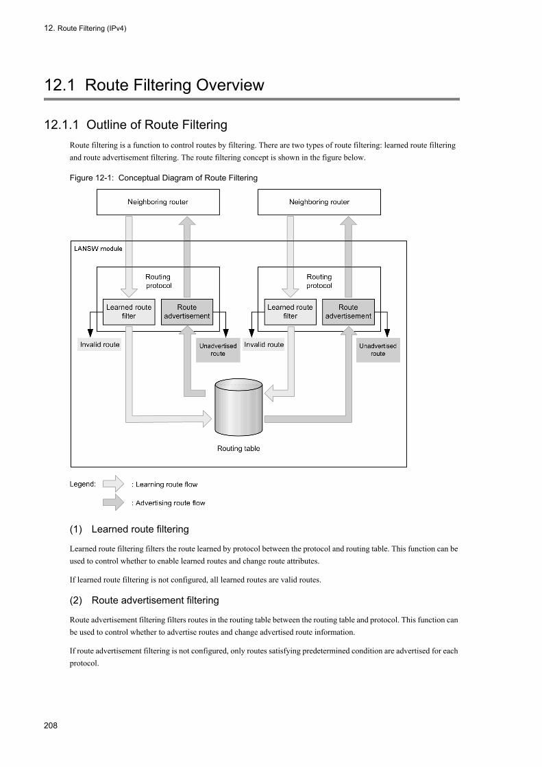
12. Route Filtering (IPv4)
12.1 Route Filtering Overview
12.1.1 Outline of Route FilteringRoute filtering is a function to control routes by filtering. There are two types of route filtering: learned route filtering and route advertisement filtering. The route filtering concept is shown in the figure below.
Figure 12-1: Conceptual Diagram of Route Filtering
(1) Learned route filtering
Learned route filtering filters the route learned by protocol between the protocol and routing table. This function can be used to control whether to enable learned routes and change route attributes.
If learned route filtering is not configured, all learned routes are valid routes.
(2) Route advertisement filtering
Route advertisement filtering filters routes in the routing table between the routing table and protocol. This function can be used to control whether to advertise routes and change advertised route information.
If route advertisement filtering is not configured, only routes satisfying predetermined condition are advertised for each protocol.
208

12. Route Filtering (IPv4)
12.1.2 Filtering MethodA filter is a list of conditions. A filter can be used for learned route filtering and route advertisement filtering by specifying a filter identifier in the route filtering configuration.
The filters that can be used for route filtering by the LANSW module are divided into two types. One is the prefix-list/access-list that filters only by destination network and the other is route-map that filters by most main route attributes and for which the route attributes can be changed. Other filters are ip as-path access-list and ip community-list which use BGP4 route attribute as conditions. ip as-path access-list and ip community-list are used by calling them from a route-map.
A filter is configured by specifying the action to take when the filter identifier and condition are satisfied. The action is either permit or deny.
More than one filter can be configured for an identifier. A filter is evaluated by checking the filter configuration of the specified identifiers in configuration display order and taking the action for the first filtering condition that is satisfied. The configuration display order is the sequence number order for filters that allow specification of sequence numbers and configuration order for filters that do not allow specification of sequence numbers.
If a specified identifier does not have a filtering configuration with activating condition matching the route, then deny is assumed. This is referred to as an implicit deny. An implicit deny is at the end of a filter with configured filtering condition.
A filter of an identifier with no filtering condition configured takes the permit action.
(1) Filtering by destination network
(a) ip prefix-list
ip prefix-list is a filter that specifies a prefix as filtering condition. When ip prefix-list is used for route filtering, the destination network of a route is compared with the prefix condition.
In addition to prefix, maximum and minimum mask length can also be specified as filtering condition. After comparing with the destination network of a route, the filtering condition is considered to be satisfied if the mask length of a destination network is within the range of the mask length specified in the condition. If a range of mask length is not specified, prefix condition is considered to be satisfied only when the mask lengths match completely. The following table shows the ip prefix-list comparison example.
Table 12-1: Comparison Example of ip prefix-list and Prefix
(Legend) Y: Match N: Not match
Compared Prefix ip prefix-list Condition
192.168.0.0/16Matches Only When Mask Length Is 16
192.168.0.0/16 ge 16 le 24Matches When Mask Length Is
between 16 and 24
192.168.0.0/16 ge 8 le 24Matches When Mask Length Is
between 8 and 24
0.0.0.0/0 N N N
192.0.0.0/8 N N Y
193.0.0.0/8 N N N
192.168.0.0/16 Y Y Y
192.169.0.0/16 N N N
192.168.43.0/24 N Y Y
192.168.42.3/32 N N N
209

12. Route Filtering (IPv4)
ip prefix-list can also be referenced as route destination condition from match ip address of route-map. The comparison method is the same as when it is used as a route filter by itself.
ip prefix-list can also be referenced as route learning source router condition from match ip route-source of route-map. In this case, the route destination condition is compared with the prefix with a mask with mask length 32 to the IPv4 address of the route learning source router added.
(b) ip access-list standard
Name 1 to 99 or 1300 to 1999 of ip access-list standard and access-list are filter setting for mainly filtering packets or login access, and can also be used for route filtering.
When ip access-list standard is used for route filtering, address section of the destination network of a route is compared with the address condition.
ip access-list standard can also be referenced as route destination condition from match ip address of route-map. The comparison method is the same as when it is used as a route filter by itself.
ip access-list standard can also be referenced as route learning source router condition from match ip route-source of route-map. In this case, IPv4 address of the learning source router is compared with the filtering condition.
(c) ip access-list extended
Name 100 to 199 or 2000 to 2699 of ip access-list extended and access-list are filter setting for mainly filtering packets or login access, and can also be used for route filtering.
When ip access-list extended is used for route filtering, address of the destination network of the route is compared with destination address condition, and mask of the destination network of the route is compared with sending source address condition. Conditions other than address such as upper protocol type and port number are all ignored.
ip access-list extended can also be referenced as route destination condition from match ip address of route-map. The comparison method is the same as when it is used as a route filter by itself.
ip access-list extended can also be referenced as route learning source router condition from match ip route-source of route-map. In this case, IPv4 address of the route learning source router is compared with the destination address condition, and mask 255.255.255.255 with mask length 32 is compared with the sending source address condition.
(2) route-map
route-map is a filter for which multiple filtering conditions of various type can be specified concurrently. In addition, route attributes can be changed when a condition is satisfied.
route-map has a sequence number. For each sequence number, a line of filtering condition can be set for each filtering condition type. Multiple filtering conditions can be specified within a line. The multiple conditions specified within a line are treated as OR conditions. The multiple conditions set in a sequence number are treated as AND conditions.
The condition for a sequence number is assumed to be satisfied if all of the specified filtering conditions are satisfied. When a condition is satisfied, the action for the sequence number is taken and the filter is terminated by that route-map.
If any of the specified filtering condition does not match, the condition of the sequence number is considered not satisfied. In this case, the next sequence number is evaluated.
The following table shows the route-map filtering condition types and the attributes that can be changed.
NoteIf multiple route-map are applied successively to a route, a change in route attribute with a route-map will affect route filtering of route-map applied later.For example, if a route-map that changes the tag value is applied with redistribute (RIP) and route-map that uses a
210
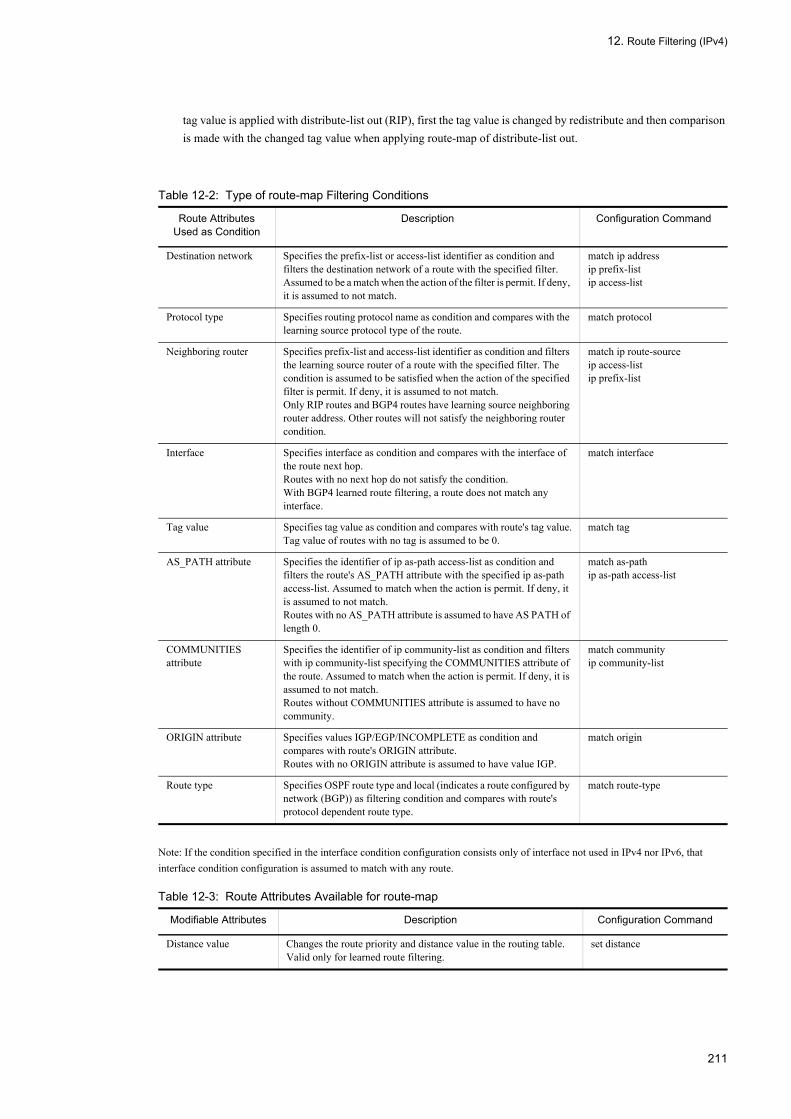
12. Route Filtering (IPv4)
tag value is applied with distribute-list out (RIP), first the tag value is changed by redistribute and then comparison is made with the changed tag value when applying route-map of distribute-list out.
Table 12-2: Type of route-map Filtering Conditions
Note: If the condition specified in the interface condition configuration consists only of interface not used in IPv4 nor IPv6, that interface condition configuration is assumed to match with any route.
Table 12-3: Route Attributes Available for route-map
Route Attributes Used as Condition
Description Configuration Command
Destination network Specifies the prefix-list or access-list identifier as condition and filters the destination network of a route with the specified filter. Assumed to be a match when the action of the filter is permit. If deny, it is assumed to not match.
match ip addressip prefix-listip access-list
Protocol type Specifies routing protocol name as condition and compares with the learning source protocol type of the route.
match protocol
Neighboring router Specifies prefix-list and access-list identifier as condition and filters the learning source router of a route with the specified filter. The condition is assumed to be satisfied when the action of the specified filter is permit. If deny, it is assumed to not match.Only RIP routes and BGP4 routes have learning source neighboring router address. Other routes will not satisfy the neighboring router condition.
match ip route-sourceip access-listip prefix-list
Interface Specifies interface as condition and compares with the interface of the route next hop.Routes with no next hop do not satisfy the condition.With BGP4 learned route filtering, a route does not match any interface.
match interface
Tag value Specifies tag value as condition and compares with route's tag value.Tag value of routes with no tag is assumed to be 0.
match tag
AS_PATH attribute Specifies the identifier of ip as-path access-list as condition and filters the route's AS_PATH attribute with the specified ip as-path access-list. Assumed to match when the action is permit. If deny, it is assumed to not match.Routes with no AS_PATH attribute is assumed to have AS PATH of length 0.
match as-pathip as-path access-list
COMMUNITIES attribute
Specifies the identifier of ip community-list as condition and filters with ip community-list specifying the COMMUNITIES attribute of the route. Assumed to match when the action is permit. If deny, it is assumed to not match.Routes without COMMUNITIES attribute is assumed to have no community.
match communityip community-list
ORIGIN attribute Specifies values IGP/EGP/INCOMPLETE as condition and compares with route's ORIGIN attribute.Routes with no ORIGIN attribute is assumed to have value IGP.
match origin
Route type Specifies OSPF route type and local (indicates a route configured by network (BGP)) as filtering condition and compares with route's protocol dependent route type.
match route-type
Modifiable Attributes Description Configuration Command
Distance value Changes the route priority and distance value in the routing table. Valid only for learned route filtering.
set distance
211

12. Route Filtering (IPv4)
(3) Other filters
In addition to filters described above, the filter which uses BGP4 route attribute as condition is available. The filters described here are used by calling then from route-map as filtering condition.
(a) ip as-path access-list
This is an AS_PATH attribute's exclusive filter. Compares with string expression of AS_PATH attribute with a regular expression as filtering condition. Used by calling from match as-path of route-map. For information on regular expression, see "(d) Regular expression".
The string expression of AS_PATH attribute is a decimal notation of AS numbers connected with blanks. This is enclosed in bracket according to path type and further connected with blanks. The string notation rules for AS_PATH attribute is shown in the table below.
Table 12-4: AS_PATH Attribute String Notation Rules
ExampleAS_SET: 100 200 300 400→ "100 200 300 400"AS_SEQ: 100 200 300, AS_SET: 1000 2000 3000, AS_CONFED_SET: 65001 65002→ "100 200 300 {1000 2000 3000} (65001 65002)"
NoteAdd the special character "\" in front of the "( )" to specify a regular expression that matches with AS_CONFED_SET. This is because the characters "( )" that represent AS_CONFED_SET is a special character in regular notation.
Metric value Changes the metric value and MED attribute. Addition and subtraction of values are allowed in addition to replacement.With BGP4 route filtering, BGP NEXT_HOP attribute can inherit a route metric.
set metricset metric-type internal (inherit route metric destined to NEXT_HOP attribute)
MED attribute
Tag value Modifies the route's tag value. set tag
LOCAL_PREF attribute Modifies the route's LOCAL_PREF attribute. Addition and subtraction of values are allowed in addition to replacement.This can be used in BGP4 route filtering.
set local-preference
AS_PATH attribute Modifies the route's AS_PATH attribute. AS number can be added. The peer's transmission side AS number is added.Used in route filtering of routes learned/advertised by BGP4 external peer.
set as-path prepend count
COMMUNITIES attribute
Modifies the route's COMMUNITIES attribute. Community can be replaced, added, or deleted.This can be used in BGP4 route filtering.
set communityset community-delete
ORIGIN attribute Modifies the route's ORIGIN attribute.This can be used in BGP4 route filtering.
set origin
OSPF metric type Modifies the metric type.This is used in OSPF route advertisement filtering.
set metric-type
Path Type Character String
AS_SEQUENCE AS number...
AS_SET {AS number...}
AS_CONFED_SEQUENCE <AS number...>
AS_CONFED_SET (AS number...)
Modifiable Attributes Description Configuration Command
212
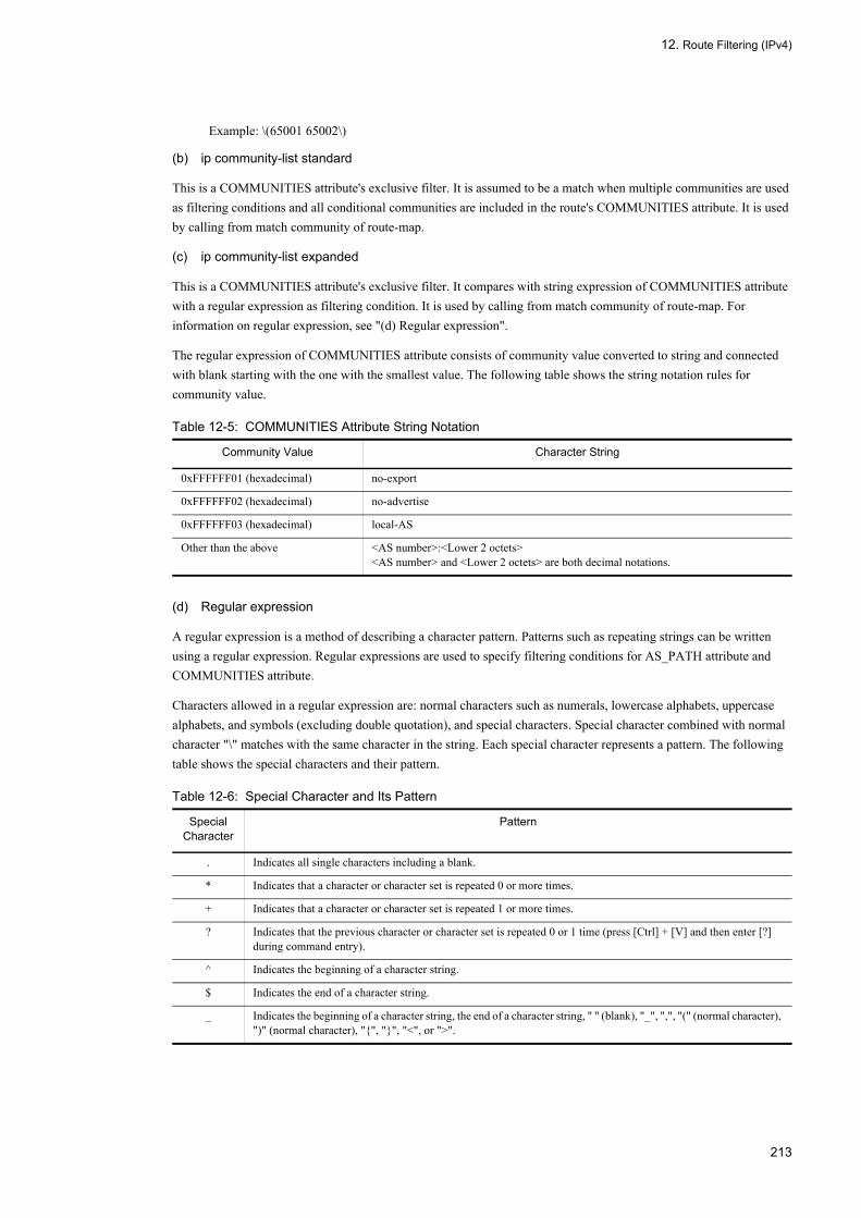
12. Route Filtering (IPv4)
Example: \(65001 65002\)
(b) ip community-list standard
This is a COMMUNITIES attribute's exclusive filter. It is assumed to be a match when multiple communities are used as filtering conditions and all conditional communities are included in the route's COMMUNITIES attribute. It is used by calling from match community of route-map.
(c) ip community-list expanded
This is a COMMUNITIES attribute's exclusive filter. It compares with string expression of COMMUNITIES attribute with a regular expression as filtering condition. It is used by calling from match community of route-map. For information on regular expression, see "(d) Regular expression".
The regular expression of COMMUNITIES attribute consists of community value converted to string and connected with blank starting with the one with the smallest value. The following table shows the string notation rules for community value.
Table 12-5: COMMUNITIES Attribute String Notation
(d) Regular expression
A regular expression is a method of describing a character pattern. Patterns such as repeating strings can be written using a regular expression. Regular expressions are used to specify filtering conditions for AS_PATH attribute and COMMUNITIES attribute.
Characters allowed in a regular expression are: normal characters such as numerals, lowercase alphabets, uppercase alphabets, and symbols (excluding double quotation), and special characters. Special character combined with normal character "\" matches with the same character in the string. Each special character represents a pattern. The following table shows the special characters and their pattern.
Table 12-6: Special Character and Its Pattern
Community Value Character String
0xFFFFFF01 (hexadecimal) no-export
0xFFFFFF02 (hexadecimal) no-advertise
0xFFFFFF03 (hexadecimal) local-AS
Other than the above <AS number>:<Lower 2 octets><AS number> and <Lower 2 octets> are both decimal notations.
Special Character
Pattern
. Indicates all single characters including a blank.
* Indicates that a character or character set is repeated 0 or more times.
+ Indicates that a character or character set is repeated 1 or more times.
? Indicates that the previous character or character set is repeated 0 or 1 time (press [Ctrl] + [V] and then enter [?] during command entry).
^ Indicates the beginning of a character string.
$ Indicates the end of a character string.
_ Indicates the beginning of a character string, the end of a character string, " " (blank), "_", ",", "(" (normal character), ")" (normal character), "{", "}", "<", or ">".
213

12. Route Filtering (IPv4)
The following table shows the connecting priority of characters used in a regular expression.
Table 12-7: Concatenation Priority of Characters Used in Regular Expression
When using a regular expression in a configuration command or operation command, enclose them in double quotation marks (").
Example 1> show ip bgp aspath-regexp "^$"
Example 2(config)# ip as-path access-list 10 permit "_100_"
12.1.3 RIP
(1) RIP learned route filtering
With RIP, all learned routes can be filtered. Routes not learned as the result of filtering are not entered in the routing table.
(a) Filter application method and application sequence
Learned routes are filtered with filter specified with distribute-list in. A filter can be applied to routes learned from a specific interface or router only by specifying the interface or router with a parameter. The following table shows the RIP learned route filtering configuration commands.
After a route is learned, apply the specified filter in the order shown in the table. If there is no filter to apply or if the results of applying a filter is all permit, the learned route is entered in the routing table as valid route. If there is any filter where the applied result is deny, that learned route is not entered in the routing table.
[ ] Indicates the single character in the character range [ ]. Characters other than the following are treated as normal characters within [ ] (does not function as special character).^: Negates the pattern when placed at the beginning of [ ] indicating a range of characters.-: Used to indicate the beginning and end of the range in [ ]. Specify so that the character code of character preceding"-" is smaller than the character code of the character following "-". See "Configuration Commands, Vol. 1, Table1-3: List of Character Code" for the character code.Example: [6-8] indicates one of the characters 6, 7, or 8. [^6-8] indicates any character other than 6, 7, or 8.
( ) Indicates the set of multiple characters. Up to nine sets can be nested.
| Indicates an OR condition.
\ When this is placed before a special character described above, it is treated as a normal character.
Precedence Character
High↑
↓Low
( )
* + ?
Normal character ., [ ], ^, $
|
Special Character
Pattern
214

12. Route Filtering (IPv4)
Table 12-8: RIP Learned Route Filtering Configuration Command
(b) Route attributes available for learned route filtering
The following table shows attributes that can be modified by RIP learned route filtering.
The modified metric value is used in RIP priority route selection. The modified distance value is used in priority route selection among routing types.
Table 12-9: Route Attributes Available for RIP Learned Route Filtering
Note• Use of method other than addition is not recommended for metric value modification. If a metric value is changed
by replacement or subtraction, a routing loop may occur and packets may not be forwarded correctly.• The metric value can be changed to 16 or greater. However, the RIP route will be invalid if the changed metric
value is 16 or greater.• Metric value modification by configuration command metric-offset is applied after learned route filtering. The
metric value changed with the route filter is further changed with metric-offset. The route is invalid if the metric value is 16 or greater after changing with metric-offset.
• The tag value can be changed regardless of the version of RIP by which route is learned. However, when advertising the changed route, only RIP version 2 advertises it with tag value added.Also, tag value can be changed up to 4294967295. However, when advertising the changed route with RIP version 2, only the low order 16 bits of the binary expression are used and the high order bits are truncated.
(2) RIP route advertisement filtering
Only the priority route in the routing table can be advertised with RIP. However, the route which does not satisfy split horizon and RIP version 1 route advertising conditions is not advertised.
If no route advertisement filtering is configured, RIP routes and direct connection routes of RIP interface are advertised.
NoteWhen advertising OSPF routes or BGP4 routes, change the metric value by configuring route advertisement filtering or advertised metric value. The above route is not advertised as is because its default advertised metric value is 16.
(a) Route attributes available for route advertisement filtering
The following table shows attributes that can be modified by RIP route advertisement filtering.
Command Parameter Filtered Route
distribute-list in (RIP) gateway <IPv4> Applies filter only to RIP route learned from the designated neighboring router.
<Interface> Applies filter only to RIP route learned from the designated IPv4 interface.
None Applies filter to all learned RIP routes.
Attribute Default Value
Distance value Value specified for distance (RIP).120 when this value is not specified.
Metric value Receive route's attribute.
Tag value Receive route's attribute.
215

12. Route Filtering (IPv4)
Table 12-10: Route Attributes Available for RIP Route Advertisement Filtering
Note• When advertising RIP route with RIP, use of metric value modification method other than addition is not
recommended. If a metric value is replaced or subtracted, a routing loop may occur and packets may not be forwarded correctly.
• The metric value can be changed to 16 or greater for the route filter. However, routes with metric value of 16 or greater is not advertised.
• Metric value modification by configuration command metric-offset is applied after route advertisement filtering. The metric value changed with the route filter is further changed with metric-offset. The route is not advertised if the metric value is 16 or greater after changing with metric-offset.
• To advertise the tag value, RIP version must be 2. If the tag value is changed to value greater than 65535, only the lower 16 bits of the binary expression are used and the upper bits are truncated.
(b) Filter application method and application sequence
Route advertisement filtering is divided into the following steps.
1. First, select the route to be advertised with RIP. Specify the learning source protocol of the route that needs to be advertised. Use the configuration command redistribute to specify the protocol. Specify a route type with redistribute, to advertise only specified type of routes. Also, specify route-map to advertise only routes that are permitted as the result of filtering with route-map. redistribute uses the route attribute in the routing table to compare the condition.The direct connection routes of RIP route and RIP interface are advertised without specifying redistribute.The attributes of the advertised route can be changed by directly specifying the route-map that changes the route attribute and route attributes in redistribute.
2. Set the metric value to the default value determined by protocol. However, if the metric value is changed with redistribute, use the value changed with redistribute.See "Table 12-10: Route Attributes Available for RIP Route Advertisement Filtering" for the default value of the RIP metric value.
3. Apply a filter according to distribute-list out, to the route selected with redistribute. A filter can be applied only when advertising to a designated destination by specifying the interface or router with a parameter. Also, by specifying a protocol, a filter is applied to just the routes learned by specified protocol. The following table shows the configuration commands.When advertising routes to RIP interface or particular neighboring router, select a filter according to advertising destination and route learning source protocol and apply it according to the sequence in the table. If there is no filter to be applied or if the filtering result is all permit, advertise the route to the specified advertising destination. If there is any filter where the applied result is deny, that route is not advertised to that advertising destination.If route-map is specified in distribute-list out, routes are filtered according to advertise default attribute and attributes
Attribute Route Learning Source Protocol
Default Value
Metric value Direct-coupled routeAggregate route
1
Static route Uses value specified with default-metric.Uses 1 if default-metric is not set.
RIP route Inherits the metric value of the route information.
OSPF routeBGP4 route
Inherits the metric value of the route information when inherit-metric is set. Uses 16 if the route information has no metric value.Uses value specified with default-metric if inherit-metric is not set.Uses 16 if neither inherit-metric nor default-metric is set.
Tag value All protocols in common Inherits the tag value of the route information.
216

12. Route Filtering (IPv4)
after they are changed with redistribute.The attributes of the advertised route can also be changed by specifying route-map that changes the attribute in distribute-list out.
Table 12-11: RIP Route Advertisement Filtering Configuration Command
12.1.4 OSPF (1) OSPF learned route filtering
With OSPF, only the AS external routes and NSSA routes of the routes determined by SPF calculation can be filtered. AS external routes and NSSA routes that will not be learned as the result of filtering are entered in the routing table as invalid routes.
Area internal routes and intra area routes are entered in the routing table without filtering.
Even when a route is disabled by learned route filtering, the corresponding route is formed for other routers. This is because LSA that was used as the source of the route is propagated to other routers in the OSPF domain. Learned route filtering filters the AS external route and NSSA routes calculated from LSA, but not the LSA that is the source of the route.
(a) Filter application method and application sequence
Filter the AS external route and NSSA route in the learned routes with the filter specified in distribute-list in. The following table shows the configuration commands used for OSPF learned route filtering.
If there is no filter to be applied or if the filtered result is permit, enter the route in the routing table as valid route. If the filtered result is deny, that route becomes an invalid route.
Table 12-12: OSPF Learned Route Filtering Configuration Command
(b) Route attributes available for learned route filtering
The following table shows attributes that can be modified by OSPF learned route filtering.
With OSPF learned route filtering, only the distance value can be changed. The modified distance value is used in priority route selection among routing types.
Command Parameter Filtered Route
distribute-list out (RIP) gateway <IPv4><Protocol>
Applies the filtering to routes of specified protocol advertising to the specified neighboring router.
gateway <IPv4> Applies the filtering to routes advertising to the specified neighboring router.
<Interface> Applies the filtering to routes advertised from specified IPv4 interface.
<Protocol> Applies the filtering to routes of specified protocol regardless of the advertising destination.
None Applies the filtering to all routes regardless of the advertising destination.
Command Filtered Route
distribute-list in (OSPF) The AS external route and NSSA route determined by the set OSPF domain is filtered.
217

12. Route Filtering (IPv4)
Table 12-13: Route Attributes Available for OSPF Learned Route Filtering
(2) OSPF route advertisement filtering
With OSPF, the direct connection route of an OSPF interface is advertised as area internal route or intra-area route. This cannot be controlled by route advertisement filtering.
Furthermore, OSPF route is also propagated to other routers. This too cannot be controlled by route filtering. This is because the route source LSA is propagated unconditionally regardless of route filtering.
Priority routes other than the above can be advertised to OSPF by route advertisement filtering. They are advertised as AS external route or NSSA route.
If route advertisement filtering is not configured, no route other than direction connection route of OSPF interface and OSPF route is advertised.
(a) Route attributes available for route advertisement filtering
The following table shows attributes that can be modified by OSPF route advertisement filtering.
Table 12-14: OSPF AS External Route Attributes Available for OSPF Route Advertisement Filtering
NoteThe metric value can be changed to 16777215 or greater. However, routes with metric value of 16777215 or greater after modification are not advertised.
(b) Filter application method and application sequence
Route advertisement filtering is divided into the following steps.
1. First, select the route to be advertised with OSPF. Specify the learning source protocol of the route that needs to be advertised. Use the configuration command redistribute to specify the protocol. However, even if the relevant OSPF domain is specified, the route of that domain is not re-advertised.Specify a route type with redistribute, to advertise only specified type of routes. Also, specify route-map to advertise only routes that are permitted as the result of filtering with route-map. redistribute uses the route attribute in the routing table to compare the condition.The attributes of the advertised route can be changed by directly specifying the route-map that changes the route attribute and route attributes in redistribute.
2. Set the metric value and OSPF route type to the default value determined by protocol. However, if the attribute value is changed with redistribute, use the value changed with redistribute.See "Table 12-14: OSPF AS External Route Attributes Available for OSPF Route Advertisement Filtering" for the
Attribute Default Value
Distance value Value specified for distance ospf (OSPF).110 when this value is not specified.
Attribute Route Learning Source Protocol
Default Value
Metric value Direct-coupled route 20
BGP4 route Value set with default-metric (OSPF) command.If default-metric setting is omitted, 1.
Others Value set with default-metric (OSPF) command.If default-metric setting is omitted, 20.
OSPF route type All protocols in common AS external route or NSSA route Type 2
Tag value All protocols in common Inherits the tag value of the route information.
218

12. Route Filtering (IPv4)
default value of the OSPF advertised route attribute.3. Apply a filter according to distribute-list out, to the route selected with redistribute. By specifying a protocol as the
parameter, filter can be applied only to routes learned by specified protocol. The following table shows the configuration commands.When advertising routes to OSPF domain, select a filter according to learning source protocol of the route and apply it according to the sequence in the table. If there is no filter to be applied or if the filtering result is all permit, that route is advertised. If there is any filter where the applied result is deny, that route is not advertised.If route-map is specified in distribute-list out, routes are filtered according to advertise default value and attributes after they are changed with redistribute.The attributes of the advertised route can also be changed by specifying route-map that changes the route attribute in distribute-list out.
NoteWhen "match route-type" is executed during route advertisement filtering by distribute-list out in step 3, either "external" or "external 1""external 2" matches. This is because the OSPF route type in the route attribute is rewritten to external route Type 1 or Type 2 by redistribute or advertisement default attribute.
Table 12-15: OSPF Route Advertisement Filtering Configuration Command
12.1.5 BGP4 (1) BGP4 learned route filtering
With BGP4, all learned routes can be filtered. By default, routes not learned as the result of filtering are not entered in the routing table.
NoteAfter configuring or changing the setting of BGP4 learned route filtering, execute the operation command clear ip bgp * in or clear ip bgp * both at the appropriate timing. The route filtering configuration before the change is effective until the above command is executed.When clear ip bgp * in is executed, the route filtering configuration after modification is used for learned route filtering. When clear ip bgp * both is executed, the route filtering configuration after modification is used for learned route filtering and route advertisement filtering.
(a) Filter application method and application sequence
The learned routes are filtered according to distribute-list in and neighbor in. The filter specified with neighbor in is applied only to routes learned from the specified peer or the peers belonging to the specified peer group. The following table shows the configuration commands used for BGP4 learned route filtering.
After a route is learned, apply the specified filter in the order shown in the table. If there is no filter to apply or if the results of applying a filter is all permit, the learned route is entered in the routing table as valid route. If there is any filter where the applied result is deny, that learned route becomes an invalid route.
Command Parameter Filtered Route
distribute-list out (OSPF) <Protocol> Applies the filtering to routes of specified protocol regardless of the advertising destination.
None Applies the filtering to all routes regardless of the advertising destination.
219

12. Route Filtering (IPv4)
Table 12-16: BGP4 Learned Route Filtering Configuration Command
(b) Route attributes available for learned route filtering
The following table shows attributes that can be modified by BGP4 route learned route filtering.
Values other than distance value are used in BGP4 priority route selection. The distance value is used in priority route selection among routing types.
Table 12-17: Route Attributes Available for BGP4 Learned Route Filtering
NoteAS can be added to AS_PATH attribute only for routes learned from external peer. AS cannot be added to AS_PATH attribute of route learned from internal peer or member AS peer.
(2) BGP4 route advertisement filtering
With BGP4, BGP4 routes that has lost priority because other routing routes where given priority and routes due to BGP4 network setting can be advertised in addition to priority route in the routing table. When advertising these three types of routes which have the same destination network, one route is selected and advertised in the order of preferred route in the routing table, previous BGP4 route and then route set by BGP4 network setting.
If route advertisement filtering is not configured, only BGP4 route is advertised. However, advertising back to the same peer as the learning source peer of the route is not possible.
NoteAfter configuring or modifying BGP4 route advertisement filtering, execute the operation command clear ip bgp * out or clear ip bgp * both at the appropriate timing. The route filtering configuration before the change is effective until the above command is executed.
Command Parameter Filtered Route
neighbor in (BGP4) (route-map specified)
<IPv4> (peer address) Only the routes learned from the specified peer are filtered.
neighbor in (BGP4) (access-list/prefix-list specified)
<IPv4> (peer address) Only the routes learned from the specified peer are filtered.
neighbor in (BGP4) (route-map specified)
<Peer-Group > (peer group) Only the routes learned from the peers belonging to the specified peer group are filtered.
neighbor in (BGP4) (access-list/prefix-list specified)
<Peer-Group > (peer group) Only the routes learned from the peers belonging to the specified peer group are filtered.
distribute-list in (BGP4) None All routes learned by BGP4 are filtered.
Attribute Default Value
Distance value Value specified with distance bgp.The following value is used if not specified.Internal peer: 200External peer: 20Member AS peer: 200
MED attribute Attribute when receiving route.
LOCAL_PREF attribute Internal peer: Attribute when receiving route.External peer: Value specified with bgp default local-preference 100 if not specified.Member AS peer: Attribute when receiving route
AS_PATH attribute Attribute when receiving route.
COMMUNITIES attribute Attribute when receiving route.
ORIGIN attribute value Attribute when receiving route.
220
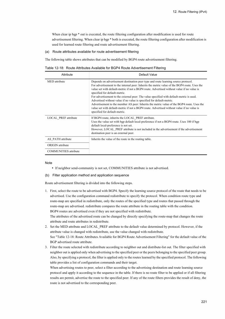
12. Route Filtering (IPv4)
When clear ip bgp * out is executed, the route filtering configuration after modification is used for route advertisement filtering. When clear ip bgp * both is executed, the route filtering configuration after modification is used for learned route filtering and route advertisement filtering.
(a) Route attributes available for route advertisement filtering
The following table shows attributes that can be modified by BGP4 route advertisement filtering.
Table 12-18: Route Attributes Available for BGP4 Route Advertisement Filtering
Note• If neighbor send-community is not set, COMMUNITIES attribute is not advertised.
(b) Filter application method and application sequence
Route advertisement filtering is divided into the following steps.
1. First, select the route to be advertised with BGP4. Specify the learning source protocol of the route that needs to be advertised. Use the configuration command redistribute to specify the protocol. When condition route type and route-map are specified in redistribute, only the routes of the specified type and routes that passed through the route-map are advertised. redistribute compares the route attribute in the routing table with the condition.BGP4 routes are advertised even if they are not specified with redistribute.The attributes of the advertised route can be changed by directly specifying the route-map that changes the route attribute and route attributes in redistribute.
2. Set the MED attribute and LOCAL_PREF attribute to the default value determined by protocol. However, if the attribute value is changed with redistribute, use the value changed with redistribute.See "Table 12-18: Route Attributes Available for BGP4 Route Advertisement Filtering" for the default value of the BGP advertised route attribute.
3. Filter the route selected with redistribute according to neighbor out and distribute-list out. The filter specified with neighbor out is applied only when advertising to the specified peer or the peers belonging to the specified peer group. Also, by specifying a protocol, the filter is applied only to the routes learned by the specified protocol. The following table provides a list of configuration commands and their target.When advertising routes to peer, select a filter according to the advertising destination and route learning source protocol and apply it according to the sequence in the table. If there is no route filter to be applied or if all filtering results are permit, advertise the route to the specified peer. If any of the route filters provides the result of deny, the route is not advertised to the corresponding peer.
Attribute Default Value
MED attribute Depends on advertisement destination peer type and route learning source protocol.For advertisement to the internal peer: Inherits the metric value of the BGP4 route. Uses the value set with default-metric if not a BGP4 route. Advertised without value if no value is specified for default-metric.For advertisement to the external peer: The value specified with default-metric is used. Advertised without value if no value is specified for default-metric.Advertisement to the member AS peer: Inherits the metric value of the BGP4 route. Uses the value set with default-metric if not a BGP4 route. Advertised without value if no value is specified for default-metric.
LOCAL_PREF attribute If BGP4 route, inherits the LOCAL_PREF attribute.Uses the value set with bgp default local-preference if not a BGP4 route. Uses 100 if bgp default local-preference is not set.However, LOCAL_PREF attribute is not included in the advertisement if the advertisement destination peer is an external peer.
AS_PATH attribute Inherits the value of the route in the routing table.
ORIGIN attribute
COMMUNITIES attribute
221
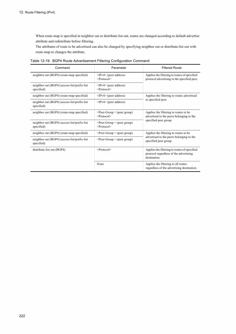
12. Route Filtering (IPv4)
When route-map is specified in neighbor out or distribute-list out, routes are changed according to default advertise attribute and redistribute before filtering.The attributes of route to be advertised can also be changed by specifying neighbor out or distribute-list out with route-map to changes the attribute.
Table 12-19: BGP4 Route Advertisement Filtering Configuration Command
Command Parameter Filtered Route
neighbor out (BGP4) (route-map specified) <IPv4> (peer address)<Protocol>
Applies the filtering to routes of specified protocol advertising to the specified peer.
neighbor out (BGP4) (access-list/prefix-list specified)
<IPv4> (peer address)<Protocol>
neighbor out (BGP4) (route-map specified) <IPv4> (peer address) Applies the filtering to routes advertised to specified peer.
neighbor out (BGP4) (access-list/prefix-list specified)
<IPv4> (peer address)
neighbor out (BGP4) (route-map specified) <Peer-Group > (peer group)<Protocol>
Applies the filtering to routes to be advertised to the peers belonging to the specified peer group.
neighbor out (BGP4) (access-list/prefix-list specified)
<Peer-Group > (peer group)<Protocol>
neighbor out (BGP4) (route-map specified) <Peer-Group > (peer group) Applies the filtering to routes to be advertised to the peers belonging to the specified peer group.neighbor out (BGP4) (access-list/prefix-list
specified)<Peer-Group > (peer group)
distribute-list out (BGP4) <Protocol> Applies the filtering to routes of specified protocol regardless of the advertising destination.
None Applies the filtering to all routes regardless of the advertising destination.
222

12. Route Filtering (IPv4)
12.2 Configuration
12.2.1 List of Configuration CommandsThe following table provides a list of route filtering configuration commands.
Table 12-20: List of Configuration Commands
Command Description
access-list Sets access list that functions as IPv4 packet filtering.
deny (ip access-list extended) Specifies the condition to deny access with IPv4 packet filter.
deny (ip access-list standard) Specifies the condition to deny access with IPv4 address filter.
distribute-list in (BGP4) Uses a filter to control whether to read the route learned by BGP4 into the routing table.
distribute-list in (OSPF) Uses a filter to control whether to read the route learned by OSPF into the routing table.
distribute-list in (RIP) Controls whether to fetch the route learned by RIP into the routing table based on the filter.
distribute-list out (BGP4) Uses a filter to control the route advertised by BGP4.
distribute-list out (OSPF) Uses a filter to control the route advertised by OSPF.
distribute-list out (RIP) Controls the route to be advertised by RIP based on the filter.
ip access-list extended Sets up the access list that operates as an IPv4 packet filtering.
ip access-list resequence Resets the sequence number of filter condition application order for IPv4 address filter and IPv4 packet filter.
ip access-list standard Sets access list that functions as IPv4 address filter.
ip as-path access-list Sets access-list that functions as AS_PATH attribute filter.
ip community-list Sets community-list that functions as COMMUNITIES attribute filter.
ip prefix-list Sets IPv4 prefix-list.
match as-path Sets filtering condition by AS_PATH attribute to route-map.
match community Sets filtering condition by COMMUNITIES attribute to route-map.
match interface Sets filtering condition by interface to route-map.
match ip address Sets filtering condition by IPv4 destination prefix to route-map.
match ip route-source Sets filtering condition by source IPv4 address to route-map.
match origin Sets filtering condition by ORIGIN attribute to route-map.
match protocol Sets filtering condition by routing protocol to route-map.
match route-type Sets filtering condition by route type to route-map.
match tag Sets filtering condition by tag to route-map.
neighbor in (BGP4) Sets the filter used for BGP4 learned route filtering.
neighbor out (BGP4) Sets the filter used for BGP4 route advertisement filtering.
permit (ip access-list extended) Specifies the condition to allow access with IPv4 packet filter.
permit (ip access-list standard) Specifies the condition to allow access with IPv4 address filter.
redistribute (BGP4) Sets the protocol type of the route to be advertised from BGP4.
redistribute (OSPF) Sets the protocol type of the route to be advertised from OSPF.
redistribute (RIP) Sets the protocol type of the route to be advertised from RIP.
223
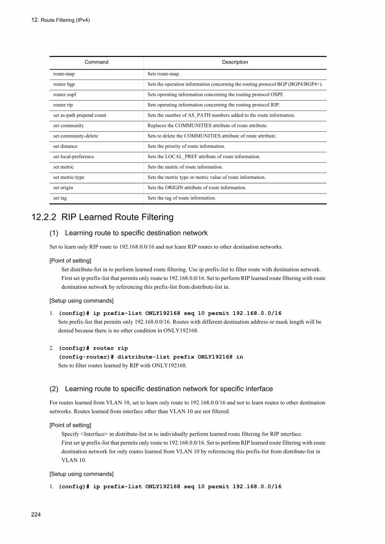
12. Route Filtering (IPv4)
12.2.2 RIP Learned Route Filtering
(1) Learning route to specific destination network
Set to learn only RIP route to 192.168.0.0/16 and not learn RIP routes to other destination networks.
[Point of setting]Set distribute-list in to perform learned route filtering. Use ip prefix-list to filter route with destination network.First set ip prefix-list that permits only route to 192.168.0.0/16. Set to perform RIP learned route filtering with route destination network by referencing this prefix-list from distribute-list in.
[Setup using commands]
1. (config)# ip prefix-list ONLY192168 seq 10 permit 192.168.0.0/16
Sets prefix-list that permits only 192.168.0.0/16. Routes with different destination address or mask length will be denied because there is no other condition in ONLY192168.
2. (config)# router rip
(config-router)# distribute-list prefix ONLY192168 in
Sets to filter routes learned by RIP with ONLY192168.
(2) Learning route to specific destination network for specific interface
For routes learned from VLAN 10, set to learn only route to 192.168.0.0/16 and not to learn routes to other destination networks. Routes learned from interface other than VLAN 10 are not filtered.
[Point of setting]Specify <Interface> in distribute-list in to individually perform learned route filtering for RIP interface.First set ip prefix-list that permits only route to 192.168.0.0/16. Set to perform RIP learned route filtering with route destination network for only routes learned from VLAN 10 by referencing this prefix-list from distribute-list in VLAN 10.
[Setup using commands]
1. (config)# ip prefix-list ONLY192168 seq 10 permit 192.168.0.0/16
route-map Sets route-map.
router bgp Sets the operation information concerning the routing protocol BGP (BGP4/BGP4+).
router ospf Sets operating information concerning the routing protocol OSPF.
router rip Sets operating information concerning the routing protocol RIP.
set as-path prepend count Sets the number of AS_PATH numbers added to the route information.
set community Replaces the COMMUNITIES attribute of route attribute.
set community-delete Sets to delete the COMMUNITIES attribute of route attribute.
set distance Sets the priority of route information.
set local-preference Sets the LOCAL_PREF attribute of route information.
set metric Sets the metric of route information.
set metric-type Sets the metric type or metric value of route information.
set origin Sets the ORIGIN attribute of route information.
set tag Sets the tag of route information.
Command Description
224

12. Route Filtering (IPv4)
Sets prefix-list that permits only 192.168.0.0/16. Routes with different destination address or mask length will be denied because there is no other condition in ONLY192168.
2. (config)# router rip
(config-router)# distribute-list prefix ONLY192168 in vlan 10
Sets to filter only routes learned from VLAN 10 with ONLY192168.
(3) Filtering learned routes by tag and destination network
Set to prevent learning of routes with destination network contained in 192.168.0.0/16 and tag value that is not 15. Sets to learn other RIP routes.
[Point of setting]Use a route-map to use something other than destination network as condition or to change the route attribute. Then reference this route-map from distribute-list in.First set prefix-list that permits when prefix is contained in 192.168.0.0/16. Then set a route-map that denies only route that permits this prefix-list and has tag value that is not 15.Finally, reference this route-map from distribute-list in to set RIP learned route filtering by both tag value and destination network.To use the tag value, RIP version should be 2. Note that the tag value is not available for RIP version 1.
[Setup using commands]
1. (config)# ip prefix-list PERMIT192168LONGER seq 10 permit 192.168.0.0/16 ge 16
le 32
Sets prefix-list that permits only routes contained in 192.168.0.0/16.
2. (config)# route-map TAG permit 10
(config-route-map)# match ip address prefix-list PERMIT192168LONGER
(config-route-map)# match tag 15
(config-route-map)# exit
Sets to permit routes contained in 192.168.0.0/16 and has tag value 15.
3. (config)# route-map TAG deny 20
(config-route-map)# match ip address prefix-list PERMIT192168LONGER
(config-route-map)# exit
Sets to not to match sequence number 10 and deny routes contained in 192.168.0.0/16.
4. (config)# route-map TAG permit 30
(config-route-map)# exit
Sets to permit routes that do not match both sequence number 10 and 20.
5. (config)# router rip
(config-router)# distribute-list route-map TAG in
Sets to prevent learning of only RIP routes contained in 192.168.0.0/16 and has tag that is not 15 by applying the above filter to RIP learned route filtering.
(4) Changing distance value by destination network
Set the distance value to 50 in order to give RIP learned routes with destination network contained in 192.168.0.0/16 priority over OSPF routes.
225

12. Route Filtering (IPv4)
[Point of setting]First set ip prefix-list that permits only routes that contain 192.168.0.0/16. Then set a route-map that changes the distance value to 50 if this prefix-list is permit.Finally, reference this route-map from distribute-list in to set RIP learned route filtering that changes the distance value based on the destination network.
[Setup using commands]
1. (config)# ip prefix-list PERMIT192168LONGER seq 10 permit 192.168.0.0/16 ge 16
le 32
Sets prefix-list that permits only routes contained in 192.168.0.0/16.
2. (config)# route-map Distance50 permit 10
(config-route-map)# match ip address prefix-list PERMIT192168LONGER
(config-route-map)# set distance 50
(config-route-map)# exit
Sets to permit routes contained in 192.168.0.0/16 by changing the distance value to 50.
3. (config)# route-map Distance50 permit 20
(config-route-map)# exit
Sets to permit routes that do not match with sequence number 10 without changing anything.
4. (config)# router rip
(config-router)# distribute-list route-map Distance50 in
Sets to change the distance value to 50 of only RIP learned routes contained in 192.168.0.0/16 by applying the above filter to RIP learned route filtering.
12.2.3 RIP Route Advertisement Filtering
(1) Advertising specific protocol routes
Set to advertise static routes and OSPF domain 1 routes by RIP.
[Point of setting]Set redistribute to advertise routes that are not advertised by default. Specify the protocol of the route that needs to be advertised for redistribute.At the same time, specify the metric value in the advertise setting of OSPF route. OSPF routes and BGP4 routes are not advertised unless metric value is specified.
[Setup using commands]
1. (config)# router rip
(config-router)# redistribute static
Advertises static routes to RIP.
2. (config-router)# redistribute ospf 1 metric 2
Advertises OSPF domain 1 routes with metric 2.
(2) Advertising specific protocol route to specific destination network
Set the RIP to advertise only static routes and OSPF routes with 192.168.0.0/16 as destination network.
226

12. Route Filtering (IPv4)
[Point of setting]Specify route-map in redistribute when performing route advertisement filtering by learning source protocol. Use ip prefix-list to use destination network as condition in route-map.First set ip prefix-list that permits only route to 192.168.0.0/16. Then set a route-map that uses this prefix-list as condition. Finally, specify static route and OSPF route with redistribute. Specify this route-map for redistribute of OSPF route.
[Setup using commands]
1. (config)# ip prefix-list ONLY192168 seq 10 permit 192.168.0.0/16
Sets prefix-list that permits only 192.168.0.0/16. Routes with different destination address or mask length will be denied because there is no other condition in ONLY192168.
2. (config)# route-map ONLY192168 permit 10
(config-route-map)# match ip address ONLY192168
(config-route-map)# exit
Sets route-map that permits only routes with 192.168.0.0/16 as destination network.
3. (config)# router rip
(config-router)# redistribute static
Advertises static routes with RIP.
4. (config-router)# redistribute ospf 1 metric 2 route-map ONLY192168
Filters OSPF domain 1 route with ONLY192168 and advertises only permitted routes.
(3) Suppressing route advertisement suppression to specific destination network
Suppress RIP advertisement only for routes to 192.168.0.0/16.
[Point of setting]Use distribute-list out to perform route advertisement filtering regardless of the route's learning source protocol.First set ip prefix-list that denies only route to 192.168.0.0/16. Set to perform RIP route advertisement filtering with route destination network by referencing this prefix-list from distribute-list out.
[Setup using commands]
1. (config)# ip prefix-list OMIT192168 seq 10 deny 192.168.0.0/16
Sets prefix-list that denies 192.168.0.0/16.
2. (config)# ip prefix-list OMIT192168 seq 100 permit 0.0.0.0/0 ge 0 le 32
Sets ip prefix-list to permit any destination address and mask length. This filter will deny only 192.168.0.0/16 because OMIT192168 has no other condition.
3. (config)# router rip
(config-router)# distribute-list prefix OMIT192168 out
Sets to filter all routes advertised by RIP with OMIT192168.
(4) Advertising destination interface specific route advertisement filtering
Advertise only 192.168.0.0/16 from RIP interface VLAN 10. Advertises routes other than 192.168.0.0/1 from RIP interface VLAN 20. Interface specific filtering is not performed with other RIP interfaces.
227

12. Route Filtering (IPv4)
[Point of setting]Specify <Interface> in distribute-list out if you need to individually perform route filtering for RIP interface.Set ip prefix-list that permits only 192.168.0.0/16 and ip prefix-list that permits only routes other than 192.168.0.0/16. Then set distribute-list out <Interface> to RIP interface VLAN 10 and VLAN 20. For distribute-list out <Interface>, specify the prefix-list appropriate for the RIP interface.
[Setup using commands]
1. (config)# ip prefix-list ONLY192168 seq 10 permit 192.168.0.0/16
Sets ip prefix-list that permits only 192.168.0.0/16. Routes with different destination address or mask length will be denied because there is no other condition in ONLY192168.
2. (config)# ip prefix-list OMIT192168 seq 10 deny 192.168.0.0/16
Sets ip prefix-list that denies only 192.168.0.0/16.
3. (config)# ip prefix-list OMIT192168 seq 100 permit 0.0.0.0/0 ge 0 le 32
Sets prefix-list to permit any destination address and mask length. This filter will deny only 192.168.0.0/16 because OMIT192168 has no other condition.
4. (config)# router rip
(config-router)# distribute-list prefix ONLY192168 out vlan 10
Sets to filter routes advertised from VLAN 10 with ONLY192168.
5. (config-router)# distribute-list prefix OMIT192168 out vlan 20
Sets to filter routes advertised from VLAN 20 with OMIT192168.
(5) Controlling route advertisement by tag
Advertise direct connection route with tag 210. Advertise only static routes with tag value 211. In addition, suppresses advertising from RIP, RIP routes with tag value 210 or 211. This prevents routes that the LANSW module started advertising to RIP from looping via the LANSW module.
To use the tag value, RIP version should be 2. Note that the tag value is not available for RIP version 1.
[Point of setting]Use route-map to use something other than destination network as condition or to change the route attribute other than metric value. route-map can be specified with redistribute and distribute-list out.Set route-map that sets the direct connection route tag to 210, permits only routes with static route tag 211, and denies routes with RIP tag 210 or 211.
[Setup using commands]
1. (config)# route-map ConnectedToRIP permit 10
(config-route-map)# set tag 210
(config-route-map)# exit
Sets route-map that sets tag to 210.
2. (config)# route-map StaticToRIP permit 10
(config-route-map)# match tag 211
(config-route-map)# exit
Sets route-map that permits only routes with tag 211.
228

12. Route Filtering (IPv4)
3. (config)# route-map RIPToRIP deny 10
(config-route-map)# match tag 210 211
(config-route-map)# exit
(config)# route-map RIPToRIP permit 20
(config-route-map)# exit
Sets route-map that denies routes with tag 210 or 211 and permits other routes.
4. (config)# router rip
(config-router)# version 2
(config-router)# redistribute connected route-map ConnectedToRIP
Advertises direct connection routes to RIP. Specify ConnectedToRIP as advertising condition.
5. (config-router)# redistribute static route-map StaticToRIP
Advertises static routes to RIP. Specify StaticToRIP as advertising condition.
6. (config-router)# redistribute rip route-map RIPToRIP
Advertises RIP routes to RIP. Specify RIPToRIP as advertising condition.
12.2.4 OSPF Learned Route Filtering
(1) Learning route to specific destination network
Set to learn only route to 192.168.0.0/16 and not learn routes to other destination networks.
[Point of setting]Set distribute-list in to perform learned route filtering. Use ip prefix-list to filter route with destination network.First set ip prefix-list that permits only route to 192.168.0.0/16. Set to perform OSPF learned route filtering with route destination network by referencing this prefix-list from distribute-list in.
[Setup using commands]
1. (config)# ip prefix-list ONLY192168 seq 10 permit 192.168.0.0/16
Sets prefix-list that permits only 192.168.0.0/16. Routes with different destination address or mask length will be denied because there is no other condition in ONLY192168.
2. (config)# router ospf 1
(config-router)# distribute-list prefix ONLY192168 in
Sets to filter learned OSPF AS external routes and NSSA routes with ONLY192168.
(2) Filtering learned routes by tag
This setting is to avoid learning routes with the tag value set to 15. Other routes are learned.
[Point of setting]Use a route-map to use something other than destination network as condition or to change the route attribute. Then reference this route-map from distribute-list in.First, set route-map that denies routes with tag value 15. Then, reference this route-map from distribute-list in to set OSPF learned route filtering by tag value.
[Setup using commands]
1. (config)# route-map TAG15DENY deny 10
229
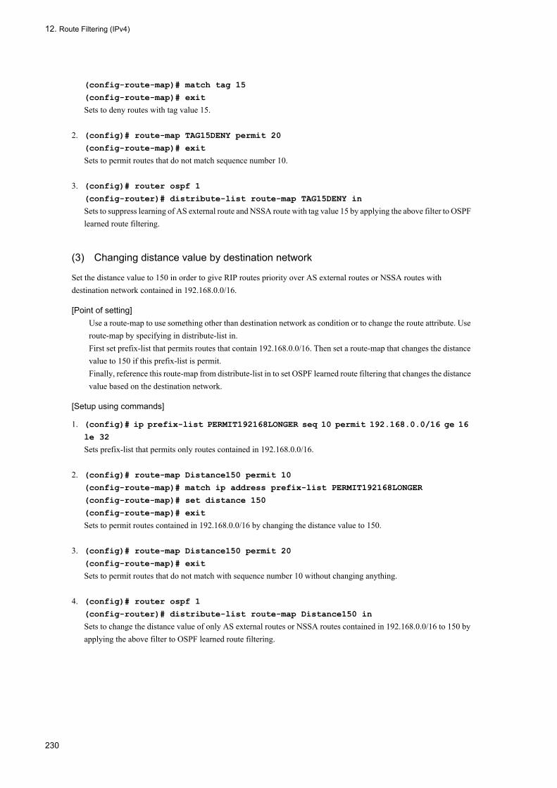
12. Route Filtering (IPv4)
(config-route-map)# match tag 15
(config-route-map)# exit
Sets to deny routes with tag value 15.
2. (config)# route-map TAG15DENY permit 20
(config-route-map)# exit
Sets to permit routes that do not match sequence number 10.
3. (config)# router ospf 1
(config-router)# distribute-list route-map TAG15DENY in
Sets to suppress learning of AS external route and NSSA route with tag value 15 by applying the above filter to OSPF learned route filtering.
(3) Changing distance value by destination network
Set the distance value to 150 in order to give RIP routes priority over AS external routes or NSSA routes with destination network contained in 192.168.0.0/16.
[Point of setting]Use a route-map to use something other than destination network as condition or to change the route attribute. Use route-map by specifying in distribute-list in.First set prefix-list that permits routes that contain 192.168.0.0/16. Then set a route-map that changes the distance value to 150 if this prefix-list is permit.Finally, reference this route-map from distribute-list in to set OSPF learned route filtering that changes the distance value based on the destination network.
[Setup using commands]
1. (config)# ip prefix-list PERMIT192168LONGER seq 10 permit 192.168.0.0/16 ge 16
le 32
Sets prefix-list that permits only routes contained in 192.168.0.0/16.
2. (config)# route-map Distance150 permit 10
(config-route-map)# match ip address prefix-list PERMIT192168LONGER
(config-route-map)# set distance 150
(config-route-map)# exit
Sets to permit routes contained in 192.168.0.0/16 by changing the distance value to 150.
3. (config)# route-map Distance150 permit 20
(config-route-map)# exit
Sets to permit routes that do not match with sequence number 10 without changing anything.
4. (config)# router ospf 1
(config-router)# distribute-list route-map Distance150 in
Sets to change the distance value of only AS external routes or NSSA routes contained in 192.168.0.0/16 to 150 by applying the above filter to OSPF learned route filtering.
230
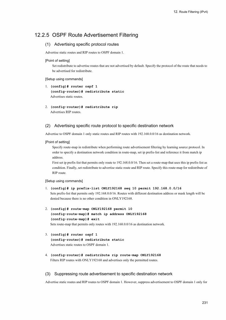
12. Route Filtering (IPv4)
12.2.5 OSPF Route Advertisement Filtering (1) Advertising specific protocol routes
Advertise static routes and RIP routes to OSPF domain 1.
[Point of setting]Set redistribute to advertise routes that are not advertised by default. Specify the protocol of the route that needs to be advertised for redistribute.
[Setup using commands]
1. (config)# router ospf 1
(config-router)# redistribute static
Advertises static routes.
2. (config-router)# redistribute rip
Advertises RIP routes.
(2) Advertising specific route protocol to specific destination network
Advertise to OSPF domain 1 only static routes and RIP routes with 192.168.0.0/16 as destination network.
[Point of setting]Specify route-map in redistribute when performing route advertisement filtering by learning source protocol. In order to specify a destination network condition in route-map, set ip prefix-list and reference it from match ip address.First set ip prefix-list that permits only route to 192.168.0.0/16. Then set a route-map that uses this ip prefix-list as condition. Finally, set redistribute to advertise static route and RIP route. Specify this route-map for redistribute of RIP route.
[Setup using commands]
1. (config)# ip prefix-list ONLY192168 seq 10 permit 192.168.0.0/16
Sets prefix-list that permits only 192.168.0.0/16. Routes with different destination address or mask length will be denied because there is no other condition in ONLY192168.
2. (config)# route-map ONLY192168 permit 10
(config-route-map)# match ip address ONLY192168
(config-route-map)# exit
Sets route-map that permits only routes with 192.168.0.0/16 as destination network.
3. (config)# router ospf 1
(config-router)# redistribute static
Advertises static routes to OSPF domain 1.
4. (config-router)# redistribute rip route-map ONLY192168
Filters RIP routes with ONLY192168 and advertises only the permitted routes.
(3) Suppressing route advertisement to specific destination network
Advertise static routes and RIP routes to OSPF domain 1. However, suppress advertisement to OSPF domain 1 only for
231

12. Route Filtering (IPv4)
routes to 192.168.0.0/16.
[Point of setting]Use distribute-list out to perform route advertisement filtering regardless of the route's learning source protocol.First set ip prefix-list that denies only route to 192.168.0.0/16. Set to perform route advertisement filtering with route destination network by referencing this prefix-list from distribute-list out.Finally, set redistribute to advertise static route and RIP route.
[Setup using commands]
1. (config)# ip prefix-list OMIT192168 seq 10 deny 192.168.0.0/16
Sets prefix-list that denies 192.168.0.0/16.
2. (config)# ip prefix-list OMIT192168 seq 100 permit 0.0.0.0/0 ge 0 le 32
Sets prefix-list to permit any destination address and mask length. This filter will deny only 192.168.0.0/16 because OMIT192168 has no other condition.
3. (config)# router ospf 1
(config-router)# distribute-list prefix OMIT192168 out
Sets to filter advertised routes with OMIT192168.
4. (config-router)# redistribute static
(config-router)# redistribute rip
Sets to advertise static routes and RIP routes.
(4) Advertising OSPF intra domain route
Mutually advertise routes between OSPF domain 1 and OSPF domain 2.
Adds tag value 1001 to OSPF domain 1 route and advertises it to OSPF domain 2. Advertisement to OSPF domain 2 is disabled when tag value 1001 is added to OSPF domain 1. This prevents routing loop because OSPF domain 1 route is not advertised back to OSPF domain 1 through OSPF domain 2.
Similarly, adds tag value 1002 to OSPF domain 2 route and advertises it to OSPF domain 1. Advertisement to OSPF domain 2 is disabled when tag value 1002 is added to OSPF domain 1.
[Point of setting]Use route-map to use something other than destination network as condition or to change the route attribute other than metric value. route-map can be specified with redistribute and distribute-list out.Set route-map for advertising to OSPF domain 1 that denies if tag 1001 is added and adds tag 1002 and permits if not. Specify this for a redistribute that advertises OSPF domain 1 route of OSPF domain 2.Similarly, set route-map for advertising to OSPF domain 2 that denies if tag 1002 is added and adds tag 1001 and permits if not. Specify this for a redistribute that advertises OSPF domain 1 route of OSPF domain 2.
[Setup using commands]
1. (config)# route-map OSPF2to1 deny 10
(config-route-map)# match tag 1001
(config-route-map)# exit
Sets OSPFv2to1 to deny routes with tag value 1001.
2. (config)# route-map OSPF2to1 permit 20
(config-route-map)# set tag 1002
232

12. Route Filtering (IPv4)
(config-route-map)# exit
Sets to change the tag to 1002 if the above is not satisfied.
3. (config)# router ospf 1
(config-router)# redistribute ospf 2 route-map OSPF2to1
(config-router)# exit
Advertises OSPF domain 2 routes to OSPF domain 1. Specify OSPF2to1 as filter.
4. (config)# route-map OSPF1to2 deny 10
(config-route-map)# match tag 1002
(config-route-map)# exit
(config)# route-map OSPF1to2 permit 20
(config-route-map)# set tag 1001
(config-route-map)# exit
Sets OSPF1to2 so as to deny when tag value is 1002 and change the tag to 1001 if not.
5. (config)# router ospf 2
(config-router)# redistribute ospf 1 route-map OSPF1to2
(config-router)# exit
Advertises OSPF domain 1 routes to OSPF domain 2. Specify OSPF1to2 as filter.
12.2.6 BGP4 Learned Route Filtering
(1) Learning peer common conditional route
Set to suppress learning of BGP4 routes with destination network contained in 192.168.0.0/16 and learn BGP4 routes to other destination network.
[Point of setting]Set distribute-list in to perform learned route filtering common to all peers. Use ip prefix-list to filter by destination network.First set ip prefix-list that denies when it matches with route contained in 192.168.0.0/16. Set to perform BGP4 learned route filtering with route destination network by referencing this prefix-list from distribute-list in.
[Setup using commands]
1. (config)# ip prefix-list DENY192168LONGER seq 10 deny 192.168.0.0/16 ge 16 le
32
(config)# ip prefix-list DENY192168LONGER seq 20 permit 0.0.0.0/0 ge 0 le 32
Sets prefix-list that denies only prefixes contained in 192.168.0.0/16 and permits other prefixes.
2. (config)#router bgp 65531
(config-router)# distribute-list prefix DENY192168LONGER in
Sets to apply that prefix-list to learned route filtering, common to all peers.
3. (config-router)# end
# clear ip bgp * in
Reflects the change in learned route filtering setting to operation.
233

12. Route Filtering (IPv4)
(2) Learning peer specific conditional route
For external peer, learn routes that have AS_PATH attribute of "65532 65533" excluding those with destination network private address (10.0.0.0/8, 172.16.0.0/12 and 192.168.0.0/16). Set the LOCAL_PREF attribute values of the learned routes to 200. Other routes are not learned.
[Point of setting]Set neighbor in to perform learned route filtering individually for each BGP4 peer. Use route-map for comparing condition other than destination network and attribute modification.First, set prefix-list that permits the route to the private address and ip as-path access-list that permits when AS_PATH attribute is "65532 65533". Then set a route-map that combines these two conditions. Finally, set neighbor in for peers to filter with this condition.
[Setup using commands]
1. (config)# ip prefix-list PRIVATE seq 10 permit 10.0.0.0/8 ge 8 le 32
(config)# ip prefix-list PRIVATE seq 20 permit 172.16.0.0/12 ge 12 le 32
(config)# ip prefix-list PRIVATE seq 30 permit 192.168.0.0/16 ge 16 le 32
Sets prefix-list that permits the route to the private address.
2. (config)# ip as-path access-list 2 permit "^65532_65533$"
Sets ip as-path access-list that permits when AS_PATH attribute is "65532 65533".
3. (config)# route-map BGP65532IN deny 10
(config-route-map)# match ip address prefix-list PRIVATE
(config-route-map)# exit
Sets route-map BGP65532IN that denies the route to the private address.
4. (config)# route-map BGP65532IN permit 20
(config-route-map)# match as-path 2
(config-route-map)# set local-preference 200
(config-route-map)# exit
Sets to set LOCAL_PATH attribute to 200 and permit when AS_PATH attribute matches with "65532 65533". Routes that do not match with any of these conditions will be denied because BGP65532IN does not have any other condition.
5. (config)#router bgp 65531
(config-router)# neighbor 172.17.1.1 remote-as 65532
(config-router)# neighbor 172.17.1.1 route-map BGP65532IN in
Sets to use BGP65532IN for receive route filtering of external peer.
6. (config-router)# end
# clear ip bgp * in
Reflects the change in learned route filtering setting to operation.
12.2.7 BGP4 Route Advertisement Filtering
(1) Advertising route of other protocols
Among direct connection routes and static routes, advertises to BGP4 only routes for which the local AS network (192.169.0.0/16) is internal to the destination network.
234

12. Route Filtering (IPv4)
[Point of setting]Set redistribute to advertise routes that are not advertised by default. Specify the protocol of the route that needs to be advertised for redistribute.Specify for redistribute the route-map of route advertising condition. Use prefix-list to specify the destination network condition in the route-map.
[Setup using commands]
1. (config)# ip prefix-list PERMIT192169LONGER seq 10 permit 192.169.0.0/16 ge 16
le 32
Sets prefix-list that permits only routes contained in 192.169.0.0/16.
2. (config)# route-map PERMIT192169LONGER permit 10
(config-route-map)# match ip address prefix-list PERMIT192169LONGER
(config-route-map)# exit
Sets route-map that permits only routes contained in 192.169.0.0/16.
3. (config)#router bgp 65531
(config-router)# redistribute connected route-map PERMIT192169LONGER
(config-router)# redistribute static route-map PERMIT192169LONGER
For direct connection routes and static routes, sets redistribute to advertise only routes for which the result of filtering with route-map PERMIT192169LONGER is permit.
4. (config-router)# end
#clear ip bgp * out
Reflects the change in route advertisement filtering setting to operation.
(2) Changing route advertisement for each peer
For advertisement to external peer, restrict to advertise only BGP4 routes with one AS path length received from AS100, and direct connection routes and static routes (192.169.0.0/16) for which the network in the local AS is the destination. When advertising, two AS_PATH AS numbers are added to peer 172.18.1.1. Only BGP4 routes are advertised to internal peer.
[Point of setting]Set neighbor out if route filtering is necessary individually for each peer.In this case, set route-maps for direct connection route/static route redistribute, for peer 172.18.1.1 advertising, for external peers other than 172.18.1.1, and for internal peer.For direct connection routes/static routes, set ip prefix-list that permits only routes contained in 192.169.0.0/16 and set route-map that references this.For peer 172.18.1.1, set route-map that adds two ASs only when route protocol is direct connection of static.For external peer other than 172.18.1.1, set ip as-path access-list that permits only AS_PATH attribute with one AS and set route-map that references this.For internal peer, set route-map that permits only BGP4 routes and denies others.
[Setup using commands]
1. (config)# ip prefix-list PERMIT192169LONGER seq 10 permit 192.169.0.0/16 ge 16
le 32
(config)# route-map PERMIT192169LONGER permit 10
(config-route-map)# match ip address prefix-list PERMIT192169LONGER
(config-route-map)# exit
235

12. Route Filtering (IPv4)
Sets route-map that permits only routes contained in 192.169.0.0/16. Use for redistribute of direct connection routes/static routes.
2. (config)# ip as-path access-list 1 permit "^[0-9]+$"
(config)# route-map BGPEXTOUT permit 10
(config-route-map)# match protocol connected static
(config-route-map)# exit
(config)# route-map BGPEXTOUT permit 20
(config-route-map)# match protocol bgp
(config-route-map)# match as-path 1
(config-route-map)# exit
Sets route-map that permits only routes with one AS number of AS_PATH attribute among direct connection routes, static routes, and BGP4 routes. Use to advertise to external peers.
3. (config)# route-map BGP1721811OUT permit 10
(config-route-map)# match protocol connected static
(config-route-map)# set as-path prepend count 2
(config-route-map)# exit
(config)# route-map BGP1721811OUT permit 20
(config-route-map)# match protocol bgp
(config-route-map)# match as-path 1
(config-route-map)# set as-path prepend count 2
(config-route-map)# exit
Sets route-map that permits only routes with one AS number of AS_PATH attribute and adds two ASs among direct connection routes, static routes, and BGP4 routes. Use to advertise to peer 172.18.1.1.
4. (config)# route-map BGPINTOUT permit 10
(config-route-map)# match protocol bgp
(config-route-map)# exit
Sets route-map that permits only BGP4 routes. Use to advertise to internal peers.
5. (config)#router bgp 65531
(config-router)# redistribute connected route-map PERMIT192169LONGER
(config-router)# redistribute static route-map PERMIT192169LONGER
For direct connection routes and static routes, sets redistribute to advertise only routes for which the result of filtering with route-map PERMIT192169LONGER is permit.
6. (config-router)# neighbor 172.17.1.1 remote-as 65532
(config-router)# neighbor 172.17.1.1 route-map BGPEXTOUT out
Uses BGPEXTOUT to filter advertised route to external peer.
7. (config-router)# neighbor 172.18.1.1 remote-as 65533
(config-router)# neighbor 172.18.1.1 route-map BGP1721811OUT out
Uses BGP1721811OUT to filter advertised route to external peer 172.18.1.1.
8. (config-router)# neighbor 192.169.1.1 remote-as 65531
(config-router)# neighbor 192.169.1.1 route-map BGPINTOUT out
Uses BGPINTOUT to filter advertised route to internal peer.
9. (config-router)# end
236

12. Route Filtering (IPv4)
#clear ip bgp * out
Reflects the change in route advertisement filtering setting to operation.
237

12. Route Filtering (IPv4)
12.3 Operation
12.3.1 List of Operation CommandsThe following table provides a list of route filtering operation commands.
Table 12-21: List of Operation Commands
12.3.2 Checking Route Received by RIP (before Learned Route Filtering)Execute the operation command show ip rip with the parameter received-routes to check the routes received by RIP.
Figure 12-2: Display Example of RIP Received Route
> show ip rip received-routesDate 2005/07/14 12:00:00 UTCStatus Codes: * valid, > active Neighbor Address: 192.168.1.145 Destination Next Hop Interface Metric Tag Timer*> 172.10.1/24 192.168.1.145 VLAN0007 1 0 23s
NoteThis command does not display routes suppressed from learning by learned route filtering and RIP internal routes not given priority.
12.3.3 Checking Route from OSPF SPF Calculation Even if invalidated by filter, AS external routes or NSSA routes resulting from SPF calculation by OSPF are entered in the routing table as invalid routes. Execute the show ip route command specifying the all-routes parameter together with -T ospf external to check AS external routes or NSSA routes, including invalid routes, resulting from SPF calculation by OSPF.
Command Description
clear ip bgp Clears BGP4 session and BGP4 protocol related information, or filters receive/send route using the new BGP filter information.
dump protocols unicast Outputs the trace information and control table information collected by a unicast routing program to a file.
erase protocol-dump unicast Deletes the trace information file and control table information file created by a unicast routing program.
restart unicast Restarts the unicast routing program.
show ip bgp Displays BGP protocol information.
show ip entry Displays detailed information on specific IPv4 unicast route.
show ip ospf Displays OSPF protocol information.
show ip rip Displays RIP protocol information.
show ip route Displays a list of IPv4 unicast routes.
238

12. Route Filtering (IPv4)
Figure 12-3: Display Example of OSPF AS External Route and NSSA Routes
> show ip route all-routes -T ospf externalDate 2005/07/14 12:00:00 UTCStatus Codes: * valid, > activeTotal: 2 routes Destination Next Hop Interface Metric Protocol Age*> 200.1/24 192.168.1.145 VLAN0007 1/1 OSPF ext2 52s, Tag: 10* 200.200.1/24 192.168.1.145 VLAN0007 1/1 OSPF ext2 52s, Tag: 0
12.3.4 Checking Route Received by BGP4 (before Learned Route Filtering)
Execute the operation command show ip bgp with the parameter received-routes to check the routes received by BGP4.
Figure 12-4: Display Example of BGP4 Receive Route
> show ip bgp received-routesDate 2005/07/14 12:00:00 UTCBGP Peer: 177.7.7.145 , Remote AS: 1000Local AS: 200, Local Router ID: 200.201.202.203Status Codes: * valid, > activeOrigin Codes: i - IGP, e - EGP, ? - incomplete Network Next Hop MED LocalPref Path*> 200.1/24 192.168.1.145 - - 1000 i* 200.200.1/24 192.168.1.145 - - 1000 i
NoteThis command does not display routes suppressed from learning by learned route filtering and BGP4 internal routes not given priority.
Execute the operation command show ip bgp specifying the parameter received-routes together with -F to check the routes including detail route attributes received by BGP4. The ORIGIN, AS_PATH, MED, LOCAL_PREF, and COMMUNITIES attributes can be verified.
Figure 12-5: Display Example of BGP4 Receive Route Detail
> show ip bgp received-routes -FDate 2005/07/14 12:00:00 UTCBGP Peer: 192.168.1.145 , Remote AS: 1000Local AS: 200, Local Router ID: 192.168.1.1Status Codes: * valid, > activeRoute 200.1/24*> Next Hop 192.168.1.145 MED: -, LocalPref: -, Type: External route Origin: IGP Path: 1000 Next Hop Attribute: 192.168.1.145 Communities: 120:200Route 200.200.1/24* Next Hop 192.168.1.145 MED: -, LocalPref: -, Type: External route Origin: IGP Path: 1000 Next Hop Attribute: 192.168.1.145 Communities: 120:200
NoteThis command does not display routes suppressed from learning by learned route filtering and BGP4 internal routes not given priority.
239

12. Route Filtering (IPv4)
12.3.5 Checking Route from Learned Route FilteringRoutes resulting from learned route filtering are entered in the routing table. The learned route filtering result can be determined by display the routes in the routing table.
Execute the operation command show ip route with the parameter all-routes to display all routes in the routing table including invalid routes.
Figure 12-6: Display Example of Routing Table Route (Including Invalid Routes)
> show ip route all-routesDate 2005/07/14 12:00:00 UTCStatus Codes: * valid, > activeTotal: 12 routes Destination Next Hop Interface Metric Protocol Age*> 127/8 ---- localhost 0/0 Connected 1h 32s-*> 127.0.0.1/32 127.0.0.1 localhost 0/0 Connected 1h 32s|*> 172.10.1/24 192.168.1.145 VLAN0007 2/0 RIP 12s |*> 192.168.1/24 192.168.1.1 VLAN0007 0/0 Connected 2s | 192.168.1/24 192.168.1.1 VLAN0007 1/- OSPF intra 48m 3s|*> 192.168.1.1/32 192.168.1.1 VLAN0007 0/0 Connected 1h 31s|**> 200.1/24 192.168.1.145 VLAN0007 -/- BGP 11m 26s|*> 201.110/24 192.168.1.145 VLAN0007 1/1 OSPF ext2 52s |*> 200.200.1/24 192.168.1.145 VLAN0007 0/0 Static 46m 58s|* 200.200.1/24 192.168.1.145 VLAN0007 -/- BGP 50m 14s|* 200.200.1/24 192.168.1.145 VLAN0007 1/1 OSPF ext2 48m 52s|* 200.200.1/24 192.168.1.145 VLAN0007 2/0 RIP 12s -
* The meaning of * and > at the beginning of the line are as follows:*: The route is a valid route. Route without * is an invalid route.>: The route is a priority route. Only priority routes are used for packet transfer.
Execute the operation command show ip route specifying the parameter all-routes together with the protocol to check routes in the routing table only for specific learning source protocol.
Figure 12-7: Display Example of Routing Table Route (Including Invalid Routes for RIP Only)
> show ip route all-routes ripDate 2005/07/14 12:00:00 UTCStatus Codes: * valid, > activeTotal: 2 routes Destination Next Hop Interface Metric Protocol Age*> 172.10.1/24 192.168.1.145 VLAN0007 2/0 RIP 12s* 200.200.1/24 192.168.1.145 VLAN0007 2/0 RIP 12s
The protocol and priority of priority route must be checked when various routing protocols are learning and using routes for a single destination network. The priority is determined by the distance value.
Execute the operation command show ip route specifying the parameter all-routes together with -P to display the route distance values. The first value of the Distance item at the end of the line is the distance value.
240

12. Route Filtering (IPv4)
Figure 12-8: Display Example of Route Distance Value in Routing Table
> show ip route all-routes -PDate 2005/07/14 12:00:00 UTCStatus Codes: * valid, > activeTotal: 12 routes Destination Next Hop Interface Metric Protocol Age*> 127/8 ---- localhost 0/0 Connected 1h 36m,Distance: 0/0/0*> 127.0.0.1/32 127.0.0.1 localhost 0/0 Connected 1h 36m,Distance: 0/0/0*> 172.10.1/24 192.168.1.145 VLAN0007 2/0 RIP 12s,Distance: 120/0/0*> 192.168.1/24 192.168.1.1 VLAN0007 0/0 Connected 0s,Distance: 0/0/0 192.168.1/24 192.168.1.1 VLAN0007 1/- OSPF intra 52m 32s,Distance: -110/1/0*> 192.168.1.1/32 192.168.1.1 VLAN0007 0/0 Connected 1h 35m,Distance: 0/0/0*> 200.1/24 192.168.1.145 VLAN0007 -/- BGP 12m 37s,Distance: 20/0/0*> 201.110/24 192.168.1.145 VLAN0007 1/1 OSPF ext2 6m 11s,Distance: 110/1/0*> 200.200.1/24 192.168.1.145 VLAN0007 0/0 Static 50m 27s,Distance: 2/0/0* 200.200.1/24 192.168.1.145 VLAN0007 -/- BGP 54m 43s,Distance: 20/0/0* 200.200.1/24 192.168.1.145 VLAN0007 1/1 OSPF ext2 52m 21s,Distance: 110/1/0* 200.200.1/24 192.168.1.145 VLAN0007 2/0 RIP 12s,Distance: 120/0/0
Execute the operation command show ip route specifying the parameter all-routes together with the destination network to display the distance values only for routes to specific destination network. The first value of the Distance display line in the detail information is the distance value.
Figure 12-9: Display Example of Routing Table Route (Including Invalid Routes, Specific Destination Only)
> show ip route all-routes 200.200.1/24Date 2005/07/14 12:00:00 UTCRoute codes: * = active, + = changed to active recently ' ' = inactive, - = changed to inactive recently Route 200.200.1/24Entries 4 Announced 1 Depth 0 <> * NextHop 192.168.1.145 , Interface : VLAN0007 Protocol <Static> Source Gateway ---- Metric/2 : 0/0 Distance/2/3: 2/0/0 Tag : 0, Age : 58m 29s AS Path : IGP (Id 1) Communities: - LocalPref : - RT State: <Remote Int Active Gateway> NextHop 192.168.1.145 , Interface : VLAN0007 Protocol <BGP> Source Gateway 192.168.1.145 Metric/2 : -/- Distance/2/3: 20/0/0 Tag : 0, Age : 1h 2m AS Path : 1000 IGP (Id 2) Communities: - LocalPref : 100 RT State: <Ext Gateway>
Execute the operation command show ip route specifying the parameter all-routes together with -F to check the detail route attributes of routes in the routing table.
241

12. Route Filtering (IPv4)
Figure 12-10: Display Example of Routing Table Route (Including Invalid Routes, Detail Display)
> show ip route all-routes -FDate 2005/07/14 12:00:00 UTCStatus Codes: * valid, > activeTotal: 12 routes Destination Next Hop Interface Metric Protocol Age*> 127/8 ---- localhost 0/0 Connected 1h 46m,Distance: 0/0/0, Tag: 0, AS-Path: IGP (Id 1), Communities: -, LocalPref: -, <NoAdvise Active Retain Reject>*> 127.0.0.1/32 127.0.0.1 localhost 0/0 Connected 1h 46m,Distance: 0/0/0, Tag: 0, AS-Path: IGP (Id 1), Communities: -, LocalPref: -, <NoAdvise Active Retain>*> 172.10.1/24 192.168.1.145 VLAN0007 2/0 RIP 19s,Distance: 120/0/0, Tag: 0, AS-Path: IGP (Id 1), Communities: -, LocalPref: -,<Int Active Gateway>*> 192.168.1/24 192.168.1.1 VLAN0007 0/0 Connected 7s,Distance: 0/0/0, Tag: 0, AS-Path: IGP (Id 1), Communities: -, LocalPref: -, <Active Retain> 192.168.1/24 192.168.1.1 VLAN0007 1/- OSPF intra 1h 2m,Distance: -110/1/0, Tag: 0, AS-Path: IGP (Id 1), Communities: -, LocalPref: -, <NotInstall NoAdvise Int Hidden Gateway>*> 177.7.7.1/32 192.168.1.1 VLAN0007 0/0 Connected 1h 45m,Distance: 0/0/0, Tag: 0, AS-Path: IGP (Id 1), Communities: -, LocalPref: -, <NoAdvise Active Retain>*> 200.1/24 192.168.1.145 VLAN0007 -/- BGP 12m 57s,Distance: 20/0/0, Tag: 0, AS-Path: 1000 IGP (Id 3), Communities: 120:200, LocalPref: 100, <Ext Active Gateway>*> 201.110.1/24 192.168.1.145 VLAN0007 1/1 OSPF ext2 3m 34s,Distance: 110/1/0, Tag: 10, AS-Path: IGP (Id 1), Communities: -, LocalPref: -, <Int Ext Active Gateway>*> 200.200.1/24 192.168.1.145 VLAN0007 0/0 Static 1h 0m,Distance: 2/0/0, Tag: 0, AS-Path: IGP (Id 1), Communities: -, LocalPref: -, <Remote Int Active Gateway>* 200.200.1/24 192.168.1.145 VLAN0007 -/- BGP 1h 5m,Distance: 20/0/0, Tag: 0, AS-Path: 1000 IGP (Id 2), Communities: -, LocalPref: 100, <Ext Gateway>* 200.200.1/24 192.168.1.145 VLAN0007 1/1 OSPF ext2 1h 2m,Distance: 110/1/0, Tag: 0, AS-Path: IGP (Id 1), Communities: -, LocalPref: -,<Int Ext Gateway>* 200.200.1/24 192.168.1.145 VLAN0007 2/0 RIP 19s,Distance: 120/0/0, Tag: 0, AS-Path: IGP (Id 1), Communities: -, LocalPref: -,<Int Gateway>
12.3.6 Checking Route before Route Advertisement FilteringRoutes subject to advertising are basically priority routes in the routing table. Display the routes in the routing table to check the routes subject to route advertisement filtering.
Execute the operation command show ip route to display the priority routes in the routing table.
Figure 12-11: Display Example of Routing Table Route
> show ip routeDate 2005/07/14 12:00:00 UTCTotal: 8 routesDestination Next Hop Interface Metric Protocol Age127/8 ---- localhost 0/0 Connected 1h 32s127.0.0.1/32 127.0.0.1 localhost 0/0 Connected 1h 32s172.10.1/24 192.168.1.145 VLAN0007 2/0 RIP 12s192.168.1/24 192.168.1.1 VLAN0007 0/0 Connected 2s192.168.1.1/32 192.168.1.1 VLAN0007 0/0 Connected 1h 31s200.1/24 192.168.1.145 VLAN0007 -/- BGP 11m 26s201.110/24 192.168.1.145 VLAN0007 1/1 OSPF ext2 52s200.200.1/24 192.168.1.145 VLAN0007 0/0 Static 46m 58s
Execute the operation command show ip route with the protocol as parameter to display priority routes in the routing table only for specific learning source protocol.
242
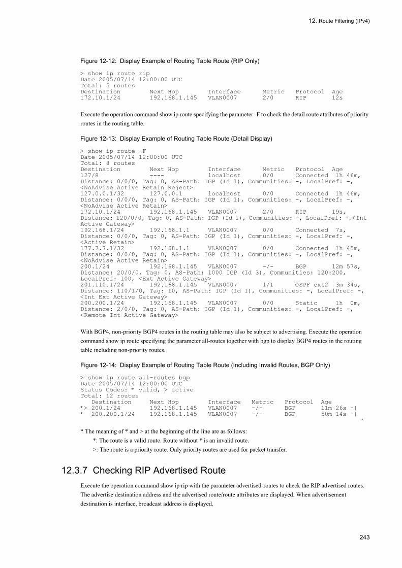
12. Route Filtering (IPv4)
Figure 12-12: Display Example of Routing Table Route (RIP Only)
> show ip route ripDate 2005/07/14 12:00:00 UTCTotal: 5 routesDestination Next Hop Interface Metric Protocol Age172.10.1/24 192.168.1.145 VLAN0007 2/0 RIP 12s
Execute the operation command show ip route specifying the parameter -F to check the detail route attributes of priority routes in the routing table.
Figure 12-13: Display Example of Routing Table Route (Detail Display)
> show ip route -FDate 2005/07/14 12:00:00 UTCTotal: 8 routesDestination Next Hop Interface Metric Protocol Age127/8 ---- localhost 0/0 Connected 1h 46m,Distance: 0/0/0, Tag: 0, AS-Path: IGP (Id 1), Communities: -, LocalPref: -, <NoAdvise Active Retain Reject>127.0.0.1/32 127.0.0.1 localhost 0/0 Connected 1h 46m,Distance: 0/0/0, Tag: 0, AS-Path: IGP (Id 1), Communities: -, LocalPref: -, <NoAdvise Active Retain>172.10.1/24 192.168.1.145 VLAN0007 2/0 RIP 19s,Distance: 120/0/0, Tag: 0, AS-Path: IGP (Id 1), Communities: -, LocalPref: -,<Int Active Gateway>192.168.1/24 192.168.1.1 VLAN0007 0/0 Connected 7s,Distance: 0/0/0, Tag: 0, AS-Path: IGP (Id 1), Communities: -, LocalPref: -, <Active Retain>177.7.7.1/32 192.168.1.1 VLAN0007 0/0 Connected 1h 45m,Distance: 0/0/0, Tag: 0, AS-Path: IGP (Id 1), Communities: -, LocalPref: -, <NoAdvise Active Retain>200.1/24 192.168.1.145 VLAN0007 -/- BGP 12m 57s,Distance: 20/0/0, Tag: 0, AS-Path: 1000 IGP (Id 3), Communities: 120:200, LocalPref: 100, <Ext Active Gateway>201.110.1/24 192.168.1.145 VLAN0007 1/1 OSPF ext2 3m 34s,Distance: 110/1/0, Tag: 10, AS-Path: IGP (Id 1), Communities: -, LocalPref: -, <Int Ext Active Gateway>200.200.1/24 192.168.1.145 VLAN0007 0/0 Static 1h 0m,Distance: 2/0/0, Tag: 0, AS-Path: IGP (Id 1), Communities: -, LocalPref: -, <Remote Int Active Gateway>
With BGP4, non-priority BGP4 routes in the routing table may also be subject to advertising. Execute the operation command show ip route specifying the parameter all-routes together with bgp to display BGP4 routes in the routing table including non-priority routes.
Figure 12-14: Display Example of Routing Table Route (Including Invalid Routes, BGP Only)
> show ip route all-routes bgpDate 2005/07/14 12:00:00 UTCStatus Codes: * valid, > activeTotal: 12 routes Destination Next Hop Interface Metric Protocol Age*> 200.1/24 192.168.1.145 VLAN0007 -/- BGP 11m 26s -|* 200.200.1/24 192.168.1.145 VLAN0007 -/- BGP 50m 14s -| *
* The meaning of * and > at the beginning of the line are as follows:*: The route is a valid route. Route without * is an invalid route.>: The route is a priority route. Only priority routes are used for packet transfer.
12.3.7 Checking RIP Advertised RouteExecute the operation command show ip rip with the parameter advertised-routes to check the RIP advertised routes. The advertise destination address and the advertised route/route attributes are displayed. When advertisement destination is interface, broadcast address is displayed.
243

12. Route Filtering (IPv4)
Figure 12-15: Display Example of RIP Advertised Route
> show ip rip advertised-routesDate 2005/10/20 16:47:36 UTC Target Address: 177.7.7.255Destination Next Hop Interface Metric Tag Age192.158.1/24 192.158.1.1 VLAN0006 1 0 5s
12.3.8 Checking OSPF Advertised Route With OSPF, routes advertised by route advertisement filtering are contained in AS-External-LSA and NSSA-External-LSA.
Execute the operation command show ip ospf specifying the parameters database, external, and self-originate to check the items in AS-External-LSA generated by the local system.
Figure 12-16: Display Example of AS-External-LSA (Local System Generated Only)
> show ip ospf database external self-originateDate 2005/07/14 12:00:00 UTCDomain: 1Local Router ID : 200.199.198.197Area : 0Address State Priority Cost Neighbor DR Backup DR177.7.7.1 BackupDR 1 1 1 1.4.8.0 200.199.198.197 LS Database: AS External LinkNetwork Address: 192.168.1/24, AS Boundary Router: 200.199.198.197 ...1 LSID: 192.168.1.0 Age: 221, Length: 36 , Sequence: 80000001, Checksums: BB9C -> Type: 2, Metric: 20, Tag: 00000000, Forward: 0.0.0.0
1. Network Address (192.168.1/24) indicates the destination network of the route.
Execute the operation command show ip ospf specifying the parameters database, nssa, and self-originate to check the items in NSSA-External-LSA generated by the local system.
Figure 12-17: Display Example of NSSA-External-LSA
> show ip ospf database nssa self-originateDate 2005/07/14 12:00:00 UTCDomain: 1Local Router ID : 200.199.198.197Area : 0Address State Priority Cost Neighbor DR Backup DR177.7.7.1 BackupDR 1 1 1 1.4.8.0 200.199.198.197 LS Database: NSSA AS External LinkNetwork Address: 192.168.1/24, AS Boundary Router: 200.199.198.197 ...1 LSID: 192.168.1.0 Age: 39, Length: 36 , Sequence: 80000001, Checksums: 9FB6 -> Type: 2, Metric: 20, Tag: 00000000, Forward: 0.0.0.0
1. Network Address (192.168.1/24) indicates the destination network of the route.
12.3.9 Checking BGP4 Advertised Route Execute the operation command show ip bgp with the parameter advertised-routes to check the BGP4 advertised routes.
244
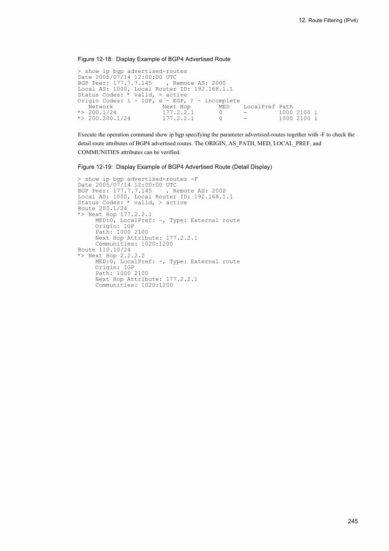
12. Route Filtering (IPv4)
Figure 12-18: Display Example of BGP4 Advertised Route
> show ip bgp advertised-routesDate 2005/07/14 12:00:00 UTCBGP Peer: 177.7.7.145 , Remote AS: 2000Local AS: 1000, Local Router ID: 192.168.1.1Status Codes: * valid, > activeOrigin Codes: i - IGP, e - EGP, ? - incomplete Network Next Hop MED LocalPref Path*> 200.1/24 177.2.2.1 0 - 1000 2100 i*> 200.200.1/24 177.2.2.1 0 - 1000 2100 i
Execute the operation command show ip bgp specifying the parameter advertised-routes together with -F to check the detail route attributes of BGP4 advertised routes. The ORIGIN, AS_PATH, MED, LOCAL_PREF, and COMMUNITIES attributes can be verified.
Figure 12-19: Display Example of BGP4 Advertised Route (Detail Display)
> show ip bgp advertised-routes -FDate 2005/07/14 12:00:00 UTCBGP Peer: 177.7.7.145 , Remote AS: 2000Local AS: 1000, Local Router ID: 192.168.1.1Status Codes: * valid, > activeRoute 200.1/24*> Next Hop 177.2.2.1 MED:0, LocalPref: -, Type: External route Origin: IGP Path: 1000 2100 Next Hop Attribute: 177.2.2.1 Communities: 1020:1200Route 110.10/24*> Next Hop 2.2.2.2 MED:0, LocalPref: -, Type: External route Origin: IGP Path: 1000 2100 Next Hop Attribute: 177.2.2.1 Communities: 1020:1200
245

12. Route Filtering (IPv4)
246

13. General Description of IPv4 Multicast
13General Description of IPv4 MulticastMulticast sends the same information to groups selected in a network. This chapter describes the multicast realized on an IPv4 network.
13.1 IPv4 Multicast Overview
13.2 IPv4 Group Management Function
13.3 IPv4 Multicast Relay Function
13.4 IPv4 Route Control Function
13.5 Network Design Concept
247

13. General Description of IPv4 Multicast
13.1 IPv4 Multicast Overview
The load on the sender and network increases when the same information is sent using multiple unicasts. Multicast sends the same information to a group selected in a network. Multicast reduces load on the network, regardless of the number of destinations, since multicast does not require the source to reproduce data individually for each one of the destinations.
The figure below is an overview of multicast.
Figure 13-1: Overview of Multicast (IPv4)
13.1.1 IPv4 Multicast AddressMulticast communication uses IP address ClassD. Multicast communication uses IP address Class D. Multicast address is a logical group address that exists only between the groups joining in transmission and reception of multicast data. The address range is 224.0.0.0 to 239.255.255.255. However, addresses 224.0.0.0 to 224.0.0.255 are reserved. The figure below shows the format of the multicast address.
Figure 13-2: Multicast Address Format
248
13. General Description of IPv4 Multicast
13.1.2 IPv4 Multicast Routing FunctionThe LANSW module forwards received multicast packets according to the multicast forwarding entry. The multicast routing function consists primarily of the three functions given below:
• Group management functionThis function sends and receives group membership information and learns of the existence of multicast groups. The Internet Group Management Protocol (IGMP) is used in the LANSW module.
• Route control functionThis function sends and receives route information, determines the forwarding route, and creates multicast route information and multicast forwarding entry. PIM-SM (including PIM-SSM) is used for collecting route information.
• Relay functionThis function forwards multicast packets via hardware and software according to the multicast forwarding entry.
249

13. General Description of IPv4 Multicast
13.2 IPv4 Group Management Function
The group management function learns of the existence of a multicast group member in the network to which a router is directly connected by sending and receiving the group membership information between the router and host. The LANSW module supports IGMP as the management protocol for implementing the group management function.
IGMP is a multicast group management protocol used between router and host. The router determines the joining or leaving of a host from a multicast group by the inquiry from the router to join a multicast group and the join/leave multicast group report from the host and forwards or blocks multicast packets.
IGMPv3, which is the extended version of IGMPv2, is the protocol to implement IPv4 group management function that has source filtering function to receive multicast packets only from the specified source. Allowing the source to be specified upon the join and leave to/from IPv4 multicast group, a combination of IGMPv3 and PIM-SSM enables efficient IPv4 multicast relay.
The format and set value of an IGMPv2 message that the LANSW module sends conform to RFC2236. The IGMPv3 message format and set values comply with RFC3376.
13.2.1 IGMP Message Support Specifications
(1) IGMPv2 message support specifications
The table below lists the specifications of IGMPv2 message supported by the LANSW module.
Table 13-1: Support Specifications of IGMPv2 Message
(Legend) Y: Supported N: Not supported -: Not applicable
(2) IGMPv3 message support specifications
IGMPv3 realizes source filtering function by specifying the filter mode and the source list. Two filter modes are available:
• INCLUDE: Relays packets only from the specified sources in the list.• EXCLUDE: Relays packets from the sources other than the specified sources in the list.
The table below lists the specifications of IGMPv3 message supported by the LANSW module.
Type Description Support
Transmission Reception
Membership Query Query to join a multicast group - -
- General Query For all groups Y Y
Group-Specific Query For specific group Y Y
Version2 Membership Report Reports the subscribed multicast group (IGMPv2 support). N Y
Leave Group Reports leaving from multicast group. N Y
Version1 Membership Report Reports the subscribed multicast group (IGMPv1 support). N Y
250

13. General Description of IPv4 Multicast
Table 13-2: Support Specifications of IGMPv3 Message
(Legend) Y: Supported N: Not supported
The filter mode and source list can be changed after joining to group, by specifying them in the Group Record included in the Report message. The table below shows the Group Record types supported by the LANSW module.
Table 13-3: Group Record Type
(Legend) Y: Supported
13.2.2 IGMP OperationIGMPv2 operation by IGMPv2 messages are described below.
• The IPv4 multicast router sends Multicast Membership Query (General Query) messages periodically to all multicast hosts 224.0.0.1 on the interface that is directly connected in order to obtain IPv4 multicast membership information.
• When Multicast Membership Query is received, the host sends Multicast Membership Report to the corresponding group to report status of joining in the group.
• IPv4 multicast router adds the group to a membership list when it receives Multicast Membership Report from the host.
• It deletes the group from the membership list when it receives a Multicast Leave Group message.
The figure below shows joining and leaving an IGMPv2 group.
Type Description Support
Transmission Reception
Version 3 Multicast Membership Query
General Query IPv4 multicast group join query (to all groups)
Y Y
Group-Specific Query IPv4 multicast group join query (to a specific group)
Y Y
Group-and-Source-Specific Query
IPv4 multicast group join query (to specific source and group).
Y Y
Version 3 MulticastMembership Report
Current StateReport Reports the joined IPv4 multicast group and the filter mode.
N Y
State ChangeReport Reports the update of joined IPv4 multicast group and the filter mode.
N Y
Type Description Support
CurrentState Report
MODE_IS_INCLUDE Indicates that the filter mode is INCLUDE. Y
MODE_IS_EXCLUDE Indicates that the filter mode is EXCLUDE.
Y(The source list is
ignored.)
State ChangeReport
CHANGE_TO_ INCLUDE_MODE Indicates that the filter mode is changed to INCLUDE.
Y
CHANGE_TO_ EXCLUDE_MODE Indicates that the filter mode is changed to EXCLUDE.
Y(The source list is
ignored.)
ALLOW_NEW_ SOURCES Indicates that the source to be allowed is added.
Y
BLOCK_OLD_ SOURCES Indicates that the allowed source is deleted.
Y
251

13. General Description of IPv4 Multicast
Figure 13-3: IGMPv2 Group Join and Leave
IGMPv3 operation by IGMPv3 messages are described below.
• The IPv4 multicast router sends Version 3 Multicast Membership Query (General Query) messages periodically to all multicast hosts 224.0.0.1 on the interface that is directly connected in order to obtain IPv4 multicast membership information.
• When Version 3 Multicast Membership Query is received, the host sends Version 3 Multicast Membership Report (Current State Report) to 224.0.0.22 to report the status of joining in the group.
• When Version 3 Multicast Membership Report (State Change Report) message is received from the host, the IPv4 multicast router adds the group to or deletes it from the membership according to the contents of the Group Record types.
The figure below shows the transmission operation of IGMPv3 message from the host.
252

13. General Description of IPv4 Multicast
Figure 13-4: IGMPv3 Group Join and Leave
13.2.3 Querier DesignationAn IGMP router acts either as a querier or a non-querier. If there are several routers on the same network, the IGMP router determines the querier that sends a periodic membership query message. The querier is determined by comparing the source IP address of the membership query received from an IGMP router on the same network with the IP address of the local interface. If the IP address of the local interface is larger, that router acts as the querier. If the local interface is smaller, the IGMP router acts as a non-querier and does not send membership query message. The above operations
253
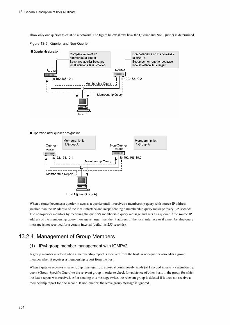
13. General Description of IPv4 Multicast
allow only one querier to exist on a network. The figure below shows how the Querier and Non-Querier is determined.
Figure 13-5: Querier and Non-Querier
When a router becomes a querier, it acts as a querier until it receives a membership query with source IP address smaller than the IP address of the local interface and keeps sending a membership query message every 125 seconds. The non-querier monitors by receiving the querier's membership query message and acts as a querier if the source IP address of the membership query message is larger than the IP address of the local interface or if a membership query message is not received for a certain interval (default is 255 seconds).
13.2.4 Management of Group Members
(1) IPv4 group member management with IGMPv2
A group member is added when a membership report is received from the host. A non-querier also adds a group member when it receives a membership report from the host.
When a querier receives a leave group message from a host, it continuously sends (at 1 second interval) a membership query (Group-Specific Query) to the relevant group in order to check for existence of other hosts in the group for which the leave report was received. After sending this message twice, the relevant group is deleted if it does not receive a membership report for one second. If non-querier, the leave group message is ignored.
254

13. General Description of IPv4 Multicast
(2) IPv4 group member management with IGMPv3
The following is an explanation of the registration and deletion of IPv4 group members with IGMPv3.
The router registers the group information when receiving the Report from the host indicating request to join to the multicast group. The group information means a group address and the source address to the group address. Querier and Non-Querier register the group information when receiving the Report.
When Querier receives the Report requesting leave from a multicast group, it sends one of the following messages in one second interval in order to check the existence of other hosts in the group.
• When no source list is specified: Group-Specific Query message• When the source list is specified: Group-and-Source-Specific Query message
When the LANSW module is the Querier, it sends this message twice and, if it does not receive the Report for one second, it deletes the group information. When the LANSW module is Non-Querier, it deletes the corresponding group information after receiving this message sent from Querier.
13.2.5 IGMP TimerThe following shows IGMPv2 timer values that the LANSW module uses.
Table 13-4: IGMPv2 Timer Value
(Legend) -: Not applicable
The following shows IGMPv3 timer values that the LANSW module uses.
Table 13-5: IGMPv3 Timer Value
Timer Contents Timer Values
(Seconds)
Remarks
Query Interval Membership Query transmission interval time 125 -
Query Response Interval Membership Report maximum response waiting time
10 -
Other Querier Present Interval Querier monitoring time 255 2 × Query Interval + Query Response Interval/2
Group Membership Interval Group member retaining time 260 2 × Query Interval + Query Response Interval
Startup Query Interval Time to transmit General Query at startup 30 -
Last Member Query Interval Specific Query transmission interval after reception of Leave request
1 -
Timer Contents Timer Values
(Seconds)
Remarks
Query Interval Membership Query transmission interval time 125 -
Query Response Interval Multicast Membership Report maximum response waiting time
10 -
Other Querier Present Interval Querier monitoring time 255 Robustness Variable × Query Interval + Query Response Interval/2*
Startup Query Interval Time to transmit General Query at startup 30 -
255

13. General Description of IPv4 Multicast
(Legend) -: Not applicable* Robustness Variable is 2 if the LANSW module is Querier, and follows Robustness Variable of Querier if the LANSW module is non-Querier.
13.2.6 Connection with IGMPv1/IGMPv2/IGMPv3 SystemThe LANSW module supports IGMPv2 and IGMPv3. The IGMP version to be used can be specified for each interface, using the configuration command ip igmp version. The table below shows the operation according to the specified version. The default is version 3.
Table 13-6: Operation With IGMP Version Specified
(1) Connection with IGMPv2/IGMPv3 router
When multiple IGMP routers exist on a single network (for example, in redundant configuration), the Querier is decided by receiving each other's Query (see "13.2.3 Querier Designation"). The LANSW module does not support the connection to IGMPv2 router on the interface with IGMP version 3 or version 3 only specified (in this case, v2 Query is ignored and Querier cannot be decided). When connecting to IGMPv2 router, set the IGMP version on the interface to version 2.
(2) Coexistence with IGMPv1 router
The LANSW module supports IGMPv2 and IGMPv3 only. IGMPv1 router must not coexist in the same network.
(3) Operation when IGMPv1/IGMPv2/IGMPv3 hosts coexist
When connecting to a network in which IGMPv1 host, IGMPv2 host, and IGMPv3 hosts coexist, use the IGMP version of the interface in the default state. However, IGMPv1 host and IGMPv2 host must be able to receive IGMPv3 Query (RFC specifications). If the IGMP version of the interface is set to version 2, coexistence of IGMPv1 host and IGMPv2 host is supported. IGMPv3 host is ignored.
If IGMPv1 host, IGMPv2 host, and IGMPv3 host coexist, group member registration depends on the version of IGMP requesting for joining in the group. Group member registration is listed in the table below for coexistence of IGMPv1 host, IGMPv2 host, and IGMPv3 host.
Last Member Query Interval Specific Query transmission interval after reception of Leave request
1 -
Group Membership Interval Group member retaining time 260 Robustness Variable × Query Interval + Query Response Interval*
Older Host Present Interval Transition period to IGMPv3 multicast address compatible mode
260 Robustness Variable × Query Interval + Query Response Interval*
Specified Version Operation per Specified Version
version 2 Operates with IGMPv2.Operates with IGMPv1 or IGMPv2 by group address. Ignores IGMPv3 packets.
version 3 Can operate with both IGMPv2 and IGMPv3.Operates with IGMPv1, IGMPv2, or IGMPv3 by group address.
version 3 only Operates with IGMPv3.Ignores IGMPv1 packets and IGMPv2 packets.
Timer Contents Timer Values
(Seconds)
Remarks
256
13. General Description of IPv4 Multicast
Table 13-7: Group Member Registration for Coexistence of IGMPv1 Host, IGMPv2 Host, and IGMPv3 Host
13.2.7 Static Group JoinA static group join function is set to relay IP multicast packets to the network in which the IGMP-compatible host does not exist.
The interface in which static group join was set operates in the same manner as a group member even if it does not receive a Membership Report message.
As this is the IGMPv2 function, it does not work if the IGMP version of the corresponding interface is set to version 3 only. If it is set to version 3, it operates in the same way as the group join with IGMPv2.
13.2.8 Notes on Using IGMP• It takes 125 seconds (maximum) to create a (*,G) entry for a PIM-SM group and a (S,G) entry for a PIM-SSM group
when static group join is set by configuration change.• When the LANSW module received IGMPv3 Report with specified source to a group with address other than SSM
addresses set in the configuration, it forwards multicast packets to the group from all sources.
Group Join Request Group Member Registration
Receives in IGMPv1. Registers the group member in IGMPv1 mode.
Receives in IGMPv2. Registers the group member in IGMPv2 mode.
Receives IGMPv3. Registers the group member in IGMPv3 mode.
Receives in IGMPv1 and IGMPv2. Registers the group member in IGMPv1 mode.
Receives in IGMPv1 and IGMPv3. Registers the group member in IGMPv1 mode.
Receives in IGMPv2 and IGMPv3. Registers the group member in IGMPv2 mode.
Receives in IGMPv1, IGMPv2, and IGMPv3. Registers the group member in IGMPv1 mode.
257

13. General Description of IPv4 Multicast
13.3 IPv4 Multicast Relay Function
Multicast packets are forwarded by hardware and software according to the multicast relay entry. Once a multicast packet is forwarded, its forwarding information is added to the hardware multicast relay entry. Packets added to the multicast forwarding entry are forwarded by hardware. Packets not added to the multicast relay entry are forwarded according to multicast relay entry created from software multicast routing information.
(1) Multicast packet forwarding by hardware
The following hardware multicast packet forwarding functions are available:
• Multicast forwarding entry searchWhen a packet to a multicast group is received, the relevant entry is searched in the hardware multicast forwarding entry.
• Multicast packet receiving interface validity checkIf an entry is found by multicast forwarding entry search, the validity of that packet's receive interface is checked.
• Multicast packet filteringForwarding is performed according to the information in the filtering table.
(2) Software forwarding of multicast packets• When there is no entry in the hardware multicast forwarding entry
When a packet from a source to a multicast group is first received, the packet is forwarded by software according to the multicast forwarding entry created from the multicast rout information. At the same time a multicast forwarding entry is registered to the hardware.
• When performing IP encapsulationPIM-SM, temporary encapsulates IP packets and forwards them to rendezvous point, and the rendezvous point forwards them to each forwarding destination after decapsulation.
(3) Multicast route information or multicast forwarding entry search
The entry corresponding to the DA (destination group address) and SA (source address) of the received multicast packet is searched from the multicast route information or multicast relay entry. The following figure shows how to search multicast route information or multicast forwarding entry.
Figure 13-6: Search Method of Multicast Route Information or Multicast Forwarding Entry
(4) Negative cache
Negative cache is a function to discard multicast packets by hardware that cannot be forwarded. Negative cache is a forwarding entry without destination interface. When a multicast packets that cannot be forwarded is received, negative cache registers it to hardware. Then when a multicast packet with the same address as the registered multicast packet is received, that packet is discarded by hardware. This prevents increase in load when large volume of multicast packets that cannot be forwarded are received.
258

13. General Description of IPv4 Multicast
13.4 IPv4 Route Control Function
The route control function creates a multicast route information and multicast forwarding entry based on the neighbor information and group information collected using a multicast routing protocol.
13.4.1 Outline of IPv4 Multicast Routing ProtocolMulticast routing protocols are a route control protocols. The LANSW module supports the following multicast routing protocols:
• PIM-SM (Protocol Independent Multicast-Sparse Mode)A protocol that performs multicast route control using unicast IPv4 route mechanism. Communication is performed via the shortest path after packets are transmitted to the rendezvous point.
• PIM-SSM (Protocol Independent Multicast-Source Specific Multicast)PIM-SSM is an extended PIM-SM function. Communication is performed via the shortest path without using any rendezvous point.
The following table shows the multicast protocol adaptations.
Table 13-8: Multicast Routing Protocol Adaptations
PIM-SM and PIM-SSM can operate simultaneously. However, PIM-SM and PIM-SSM cannot share the same group. If routers using PIM-SM, using PIM-DM, and using DVMRP coexist on the same network, no multicast packets are forwarded between the routers. To forward multicast packets between PIM-SM and PIM-SSM within the same network, configure to use the same multicast protocol on all routers. For the adaptation of each protocol, refer to "13.5.4 Notes on Network Configuration".
13.4.2 IPv4 PIM-SMPIM-SM is a multicast routing protocol used between routers which forwards and discards received multicast packets by exchanging neighbor information and join and prune requests of multicast delivery trees. The PIM-SM first relays multicast packets via the rendezvous point. Then, it uses existing unicast routing to switch to the shortest path from the multicast packet source and forwards multicast packets.
The format and settings of PIM-SM frame sent by the LANSW module conform to RFC2362.
(1) PIM-SM message support specifications
The following table shows the PIM-SM message support specifications.
Table 13-9: PIM-SM Message Support Specifications
Multicast Protocol Adaptive Network
PIM-SM Network in which multicast group members are sparse and dispersed.
PIM-SSM
Message Type Function
PIM-Hello Detects the PIM neighboring router.
PIM-Join/Prune Joins in and prunes the multicast delivery tree.
PIM-Assert Determination of Forwarder
PIM-Register IP-encapsulates multicast packets addressed to rendezvous point.
259
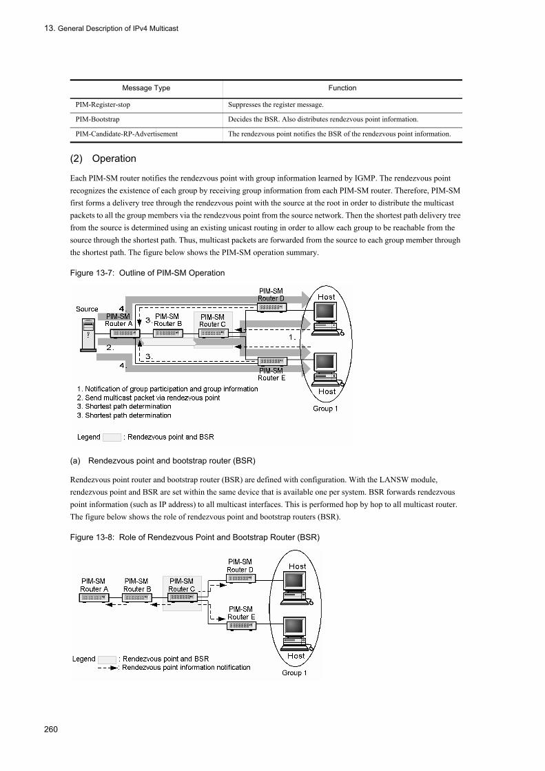
13. General Description of IPv4 Multicast
(2) Operation
Each PIM-SM router notifies the rendezvous point with group information learned by IGMP. The rendezvous point recognizes the existence of each group by receiving group information from each PIM-SM router. Therefore, PIM-SM first forms a delivery tree through the rendezvous point with the source at the root in order to distribute the multicast packets to all the group members via the rendezvous point from the source network. Then the shortest path delivery tree from the source is determined using an existing unicast routing in order to allow each group to be reachable from the source through the shortest path. Thus, multicast packets are forwarded from the source to each group member through the shortest path. The figure below shows the PIM-SM operation summary.
Figure 13-7: Outline of PIM-SM Operation
(a) Rendezvous point and bootstrap router (BSR)
Rendezvous point router and bootstrap router (BSR) are defined with configuration. With the LANSW module, rendezvous point and BSR are set within the same device that is available one per system. BSR forwards rendezvous point information (such as IP address) to all multicast interfaces. This is performed hop by hop to all multicast router. The figure below shows the role of rendezvous point and bootstrap routers (BSR).
Figure 13-8: Role of Rendezvous Point and Bootstrap Router (BSR)
PIM-Register-stop Suppresses the register message.
PIM-Bootstrap Decides the BSR. Also distributes rendezvous point information.
PIM-Candidate-RP-Advertisement The rendezvous point notifies the BSR of the rendezvous point information.
Message Type Function
260
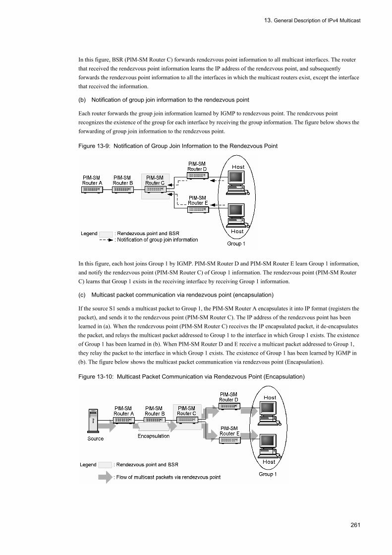
13. General Description of IPv4 Multicast
In this figure, BSR (PIM-SM Router C) forwards rendezvous point information to all multicast interfaces. The router that received the rendezvous point information learns the IP address of the rendezvous point, and subsequently forwards the rendezvous point information to all the interfaces in which the multicast routers exist, except the interface that received the information.
(b) Notification of group join information to the rendezvous point
Each router forwards the group join information learned by IGMP to rendezvous point. The rendezvous point recognizes the existence of the group for each interface by receiving the group information. The figure below shows the forwarding of group join information to the rendezvous point.
Figure 13-9: Notification of Group Join Information to the Rendezvous Point
In this figure, each host joins Group 1 by IGMP. PIM-SM Router D and PIM-SM Router E learn Group 1 information, and notify the rendezvous point (PIM-SM Router C) of Group 1 information. The rendezvous point (PIM-SM Router C) learns that Group 1 exists in the receiving interface by receiving Group 1 information.
(c) Multicast packet communication via rendezvous point (encapsulation)
If the source S1 sends a multicast packet to Group 1, the PIM-SM Router A encapsulates it into IP format (registers the packet), and sends it to the rendezvous point (PIM-SM Router C). The IP address of the rendezvous point has been learned in (a). When the rendezvous point (PIM-SM Router C) receives the IP encapsulated packet, it de-encapsulates the packet, and relays the multicast packet addressed to Group 1 to the interface in which Group 1 exists. The existence of Group 1 has been learned in (b). When PIM-SM Router D and E receive a multicast packet addressed to Group 1, they relay the packet to the interface in which Group 1 exists. The existence of Group 1 has been learned by IGMP in (b). The figure below shows the multicast packet communication via rendezvous point (Encapsulation).
Figure 13-10: Multicast Packet Communication via Rendezvous Point (Encapsulation)
261

13. General Description of IPv4 Multicast
(d) Multicast packet communication via rendezvous pint (decapsulation)
When the rendezvous point (PIM-SM Router C) receives the IP encapsulated packet, it de-encapsulates the packet, and relays the multicast packet addressed to Group 1 to the interface in which Group 1 exists, as explained in (c).
After this process, the rendezvous point reports Group 1 information in the shortest path direction to the source server. PIM-SM Router B and A having received the Group 1 information recognize (learn) the existence of Group 1 in the receiving interface. PIM-SM router A relays the multicast packet sent by source server and addressed to Group 1 to the corresponding interface without performing the IP encapsulation. PIM-SM router B, C, D, and E having received the multicast packet addressed to Group 1 relays the packet to the interface in which Group 1 exists. The figure below shows the multicast packet communication via rendezvous point (decapsulation).
Figure 13-11: Multicast Packet Communication via Rendezvous Point (Decapsulation)
(e) Multicast communication via the shortest path
If PIM-SM Router D and E received a multicast packet of to Group 1 on the source server (as explained in (c)), PIM-SM Router D and E report the Group 1 information in the direction of the shortest path (the existing unicast routing information) to sender S1. When Group 1 information is received from PIM-SM Router D and E, the PIM-SM router recognize the existence of Group 1 in the receiving interface, and relay the multicast packet of S1 addressed to Group 1 to the said interface. The figure below shows the multicast communication via the shortest path.
Figure 13-12: Multicast Communication via the Shortest Path
(f) Pruning of multicast delivery tree
If a host leaves Group 1 by IGMP, PIM-SM router D notifies the interfaces, having reported Group 1 information the Group 1 pruning information. When router A receives the pruning notification on Group 1, the router stops forwarding to the received interface of the multicast packet addressed to Group 1. The figure below shows the pruning of the multicast delivery tree.
262
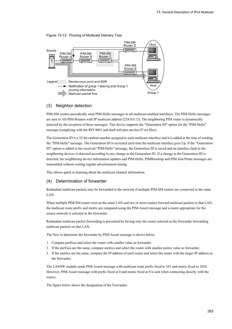
13. General Description of IPv4 Multicast
Figure 13-13: Pruning of Multicast Delivery Tree
(3) Neighbor detection
PIM-SM routers periodically send PIM-Hello messages to all multicast-enabled interfaces. The PIM-Hello messages are sent to All-PIM-Routers with IP multicast address (224.0.0.13). The neighboring PIM router is dynamically detected by the reception of these messages. This device supports the "Generation ID" option for the "PIM-Hello" message (complying with the RFC4601 and draft-ietf-pim-sm-bsr-07.txt files).
The Generation ID is a 32-bit random number assigned to each multicast interface and it is added at the time of sending the "PIM-Hello" message. The Generation ID is recreated each time the multicast interface goes Up. If the "Generation ID" option is added to the received "PIM-Hello" message, the Generation ID is saved and an interface fault in the neighboring devices is detected according to any change in the Generation ID. If a change in the Generation ID is detected, the neighboring device information updates and PIM-Hello, PIMBoostrap and PIM Join/Prune messages are transmitted without waiting regular advertisement timing.
This allows quick re-learning about the multicast channel information.
(4) Determination of forwarder
Redundant multicast packets may be forwarded to the network if multiple PIM-SM routers are connected in the same LAN.
When multiple PIM-SM router exist on the same LAN and two or more routers forward multicast packets to that LAN, the multicast route prefix and metric are compared using the PIM-Assert message and a router appropriate for the source network is selected as the forwarder.
Redundant multicast packet forwarding is prevented by having only the router selected as the forwarder forwarding multicast packets on that LAN.
The flow to determine the forwarder by PIM-Assert message is shown below.
1. Compare prefixes and select the router with smaller value as forwarder.2. If the prefixes are the same, compare metrics and select the router with smaller metric value as forwarder.3. If the metrics are the same, compare the IP address of each router and select the router with the larger IP address as
the forwarder.
The LANSW module sends PIM-Assert message with multicast route prefix fixed to 101 and metric fixed to 1024. However, PIM-Assert message with prefix fixed at 0 and metric fixed at 0 is sent when connecting directly with the source.
The figure below shows the designation of the Forwarder.
263

13. General Description of IPv4 Multicast
Figure 13-14: Determination of Forwarder
(5) DR determination and operation
If there are multiple PIM-SM routers on the same LAN, the designated router (DR) on that LAN is determined. The DR is a PIM-SM router with the largest IP address on that interface. The group join information from receiving host is notified to the rendezvous point by DR. The multicast packet sent by the source server is encapsulated and sent to rendezvous point by DR. This action is shown in the figure below.
Figure 13-15: Operation of DR
Comparing the IP address of PIM-SM router and PIM-SM Router B and if the IP address of PIM-SM Router B is larger, PIM-SM Router B notifies the group join information to rendezvous point as the DR. If the IP addresses of PIM-SM Router E is larger when comparing PIM-SM Router D and E, PIM-SM Router E relays the IP-encapsulated packet to the rendezvous point as DR.
(6) Notes on using a redundant route
In the case of the redundant configuration shown in the following figure, make sure that a multicast packet will not be forwarded. Therefore, if a redundant route exists, it is necessary to set the PIM in all the routers on that route.
264

13. General Description of IPv4 Multicast
Figure 13-16: Notes on Redundant Route
(7) PIM-SM timer specification
The table below shows the timer value used by the PIM-SM.
Table 13-10: PIM-SM Timer
Timer Name Contents Default Value (in
Second(s))
Setting Range by Configuration (in
Second(s))
Remarks
Hello-Period Hello interval 30 5 to 3600 -
Hello-Holdtime Neighbor adjacency hold time
105 3.5 × Hello-Period Calculated from expression at left.
Assert-Timeout Forwarding suppress interval due to assert
180 - -
Join/Prune-Period Join/prune transmission interval
60 30 to 3600 Up to +50% fluctuation.
Join/Prune-Holdtime Route information and forwarding interface hold time
210 3.5 × Join/Prune-Period
Calculated from expression at left.
Deletion-Delay-Time Multicast forwarding interface hold time after receiving prune
1/3 × Holding time contained in Prune received
0 to 300 *1
Data-Timeout Forwarding entry hold time 210 0 (indefinite),60 to 43200
Up to +90 second error.
Register-Supression-Timer Encapsulated transmission suppression period
60 - There is up to ± 30 second fluctuation.
Probe-Time Time to send resume acknowledge for encapsulated transmission
5 5 to 60 With the default 5 seconds, an encapsulation transmission resume acknowledge (Null-Register) is sent once 5 seconds before the Register-Supression-Timer expires.*2
C-RP-Adv-Period Rendezvous point candidate advertise cycle
60 - -
265
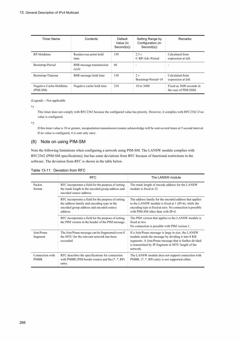
13. General Description of IPv4 Multicast
(Legend) -: Not applicable
*1This timer does not comply with RFC2362 because the configured value has priority. However, it complies with RFC2362 if no value is configured.
*2If this timer value is 10 or greater, encapsulation transmission resume acknowledge will be sent several times at 5 second interval. If no value is configured, it is sent only once.
(8) Note on using PIM-SM
Note the following limitations when configuring a network using PIM-SM. The LANSW module complies with RFC2362 (PIM-SM specifications), but has some deviations from RFC because of functional restrictions in the software. The deviation from RFC is shown in the table below.
Table 13-11: Deviation from RFC
RP-Holdtime Rendezvous point hold time
150 2.5 × C-RP-Adv-Period
Calculated from expression at left.
Bootstrap-Period BSR message transmission cycle
60 - -
Bootstrap-Timeout BSR message hold time 130 2 × Bootstrap-Period+10
Calculated from expression at left.
Negative-Cache-Holdtime(PIM-SM)
Negative cache hold time 210 10 to 3600 Fixed as 3600 seconds in the case of PIM-SSM.
RFC The LANSW module
Packetformat
RFC incorporates a field for the purpose of setting the mask length in the encoded group address and encoded source address.
The mask length of encode address for the LANSW module is fixed at 32.
RFC incorporates a field for the purpose of setting the address family and encoding type in the encoded group address and encoded source address.
The address family for the encoded address that applies to the LANSW module is fixed at 1 (IPv4), while the encoding type is fixed at zero. No connection is possible with PIM-SM other than with IPv4.
RFC incorporates a field for the purpose of setting the PIM version in the header of the PIM message.
The PIM version that applies to the LANSW module is fixed at two.No connection is possible with PIM version 1.
Join/Prune fragment
The Join/Prune message can be fragmented even if the MTU for the relevant network has been exceeded.
If a Join/Prune message is large in size, the LANSW module sends the message by dividing it into 8 KB segments. A Join/Prune message that is further divided is transmitted by IP fragment in MTU length of the network.
Connection with PMBR
RFC describes the specifications for connection with PMBR (PIM border router) and the (*, *, RP) entry.
The LANSW module does not support connection with PMBR. (*, *, RP) entry is not supported either.
Timer Name Contents Default Value (in
Second(s))
Setting Range by Configuration (in
Second(s))
Remarks
266

13. General Description of IPv4 Multicast
13.4.3 IPv4 PIM-SSMPIM-SSM is an extended PIM-SM function. PIM-SM and PIM-SSM can operate simultaneously. The multicast address that PIM-SSM uses is assigned using IANA. In the LANSW module, the range of multicast address (group address) in which PIM-SSM operates can be specified in the configuration. PIM-SM operates in those other than the specified address.
PIM-SM requires a multicast forwarding packet to create multicast entry. PIM-SSM creates a multicast forwarding entry by exchanging multicast route information (PIM-Join) and forwards multicast packet with the corresponding entry. PIM-SSM does not require a rendezvous point and bootstrap router. Therefore, the encapsulation and decapsulation of packet are not required when a multicast packet is relayed. This enables a highly-efficient multicast forwarding. Moreover, with the LANSW module, PIM-SSM can be operated in IGMPv2.
(1) Support specifications of PIM-SSM message
These are the same as the support specifications of PIM-SM ("13.4.2 IPv4 PIM-SM (1) PIM-SM message support specifications").
(2) Note on operating PIM-SSM
The following items must be configured.
• Setting of each systemSet the group address range in which PIM-SSM operates.
• System to which the host running IGMPv2 is directly connected.Set the group address and source address with which PIM-SSM operates to receive IGMPv2.
(3) PIM-SSM operation
The procedure when the multicast server (source address: S1) transmits a multicast packet to Group 1 (group address: G1) is described below.
1. An IGMPv2 report (G1) for joining in a multicast group is received from the host.2. The LANSW module that received the IGMPv2 report compares the group address (G1) notified and the group
address defined in the configuration. When the group addresses match, PIM-Join is transmitted in the shortest route direction (determined using unicast routing information) to the source address (S1) defined in the configuration. In this case, the source address (S1) and group address (G1) information is written in the PIM-Join. Each system that receives PIM-Join transmits them in the shortest route direction to source address (S1) hop-by-hop. The system that received PIM-Join learns the multicast routing information of source address (S1) and group address (G1).
3. Multicast server (S1) transmits a multicast packet to Group 1 (G1). The system receiving it relays the packet according to multicast relay entry generated from the learned multicast route information.
The figure below shows the PIM-SSM operation summary.
Switching to the shortest path
A method to switch based on the data rate is available as a switching timing to the shortest path.
The LANSW module switches to the shortest path without checking the data rate once it receives the first data in the last-hop-router.
C-RP-Adv reception and bootstrap transmission
A bootstrap message is allowed to be fragmented when the produced message length exceeds the maximum packet length. However, in order to suppress fragmentation, it is recommended to define the maximum number of the rendezvous point candidate.
The LANSW module only uses one rendezvous point and BSR in the system. Furthermore, the maximum number of group prefixes that can be set by the rendezvous point is 128.If the bootstrap message is large in size, the LANSW module transmits the message upon IP-fragmenting it in the MTU length of the network.
RFC The LANSW module
267

13. General Description of IPv4 Multicast
Figure 13-17: PIM-SSM Operation Outline
(4) Neighbor detection
Same as PIM-SM ("(3) Neighbor detection" in "13.4.2 IPv4 PIM-SM").
(5) Determination of forwarder
Same as PIM-SM ("(4) Determination of forwarder" in "13.4.2 IPv4 PIM-SM").
(6) DR determination and operation
Same as PIM-SM ("(5) DR determination and operation" in "13.4.2 IPv4 PIM-SM").
(7) Note on redundant route
Same as PIM-SM ("(6) Notes on using a redundant route" in "13.4.2 IPv4 PIM-SM").
13.4.4 IPv4 Route Control Operation with IGMPv3
(1) IPv4 PIM-SSM operation with IGMPv3
The information on the source is required to use PIM-SSM. When IGMPv2 is used with the LANSW module, setting the source in the configuration enables PIM-SSM. For IGMPv3, PIM-SSM can be used without setting the source in the configuration (PIM-SSM must be set in the configuration).
268

13. General Description of IPv4 Multicast
The IPv4 PIM-SSM operation when the multicast server (source address S1) transmits a multicast packet to multicast group G1 is as follows.
1. An IGMPv3 report (G1, S1) for joining in a multicast group is received from the host.2. The system that received the IGMPv3 Report (G1,S1) compares the group address (G1) notified by the report with
the SSM group address (range) specified in the configuration. If the group addresses match, it transmits PIM-Join containing the group address (G1) and source address (S1) in the shortest path direction to the source address (S1) notified by the Report.
3. Each system that receives PIM-Join transmits PIM-Join in the shortest route direction to source address (S1) hop-by-hop. Each system that receives PIM-Join forms a delivery tree to forward the multicast packet from the source address S1 only to the interface that received PIM-Join.
4. The system that receives the multicast packet sent by Multicast server S1 to Group G1 forwards the multicast packet according to the multicast forwarding information.
Figure 13-18: Overview of IPv4 PIM-SSM Operation with IGMPv3
(2) IPv4 PIM-SM operation with IGMPv3
If PIM-SSM is not set in the configuration, PIM-SM is applied to the operation. The IPv4 PIM-SM operation when the multicast server (source address S1) transmits a multicast packet to multicast group G1 is as follows.
1. An IGMPv3 report (G1, S1) for joining in a multicast group is received from the host.2. The system that receives the IGMPv3 Report (G1, S1) sends PIM-Join containing the group address (G1) in the
shortest route direction to the rendezvous point.
269

13. General Description of IPv4 Multicast
3. The rendezvous point that receives PIM-Join recognizes the existence of each group. The delivery tree with the source as the root is formed to deliver multicast packets from the source network to each group member via the rendezvous point.
4. The shortest path from the source is determined by using the existing unicast routing so that the source can reach each group member using the shortest path from the source (i.e., sends PIM-Join in the shortest route direction to the source and forms a shortest path delivery tree).
5. The system that receives the multicast packet sent by multicast delivery server S1 to Group G1 forwards the multicast packet according to the shortest path delivery tree.
Figure 13-19: Overview of IPv4 PIM-SM Operation with IGMPv3
(3) IPv4 route control for coexistence of IGMPv1/IGMPv2 host and IGMPv3 host
The following describes the IPv4 route control operation when IGMPv2 is set to be used with PIM-SSM while IGMPv1, IGMPv2, and IGMPv3 hosts coexist.
When the join request for the group address within the PIM -SSM target address range set on the configuration is received, PIM-SSM operates (see "Table 13-12: IPv4 Route Control Operation for Coexistence of IGMPv1/IGMPv2 and IGMPv3 Hosts"). When the join request is received through IGMPv1 Report or IGMPv2 Report, the source address set in the configuration is used as the source list. When receiving join request to the same group address in IGMPv1 Report, IGMPv2 Report, and IGMPv3 Report (EXCLUDE), a combination of the source address specified in the configuration and the source list contained in the IGMPv3 Report (INCLUDE) is used as the source list.
IPv4 route control operation for coexistence of IGMPv1/IGMPv2 and IGMPv3 hosts is listed in the table below.
Table 13-12: IPv4 Route Control Operation for Coexistence of IGMPv1/IGMPv2 and IGMPv3 Hosts
Join Group Address IGMPv1 ReportIGMPv2 Report
IGMPv3 Report (EXCLUDE)
IGMPv3 Report (INCLUDE)
Within the SSM address range PIM-SSM PIM-SSM
Out of the SSM address range PIM-SM PIM-SM
270

13. General Description of IPv4 Multicast
13.5 Network Design Concept
13.5.1 IPv4 Multicast RelayPay attention to the following when forwarding multicast packets using the LANSW module.
(1) Use of PIM-SM and PIM-SSM
(a) Operating interface
PIM-SM and PIM-SSM operates on an interface where the mask length of an IP address is 8 bits to 30 bits.
(b) Packet passing by timing
If the system receives multicast data from a sender and PIM-Join message from a receiver at the same time, some packets may be passed, resulting in the change of packet order, depending on the timing.
(c) Relay interruption due to restarting of routing program
Note that multicast communication is stopped until the multicast routing information is relearned when restarting the IP multicast routing program with the restart ipv4-multicast command.
(d) Multihome
IPv4 multicast does not operate on interface using multihome.
(2) Use of PIM-SM
Pay attention to the following when using PIM-SM.
(a) Packet loss by software relay processing
The LANSW module sets a multicast forwarding entry in hardware for performing multicast communication at first multicast packet reception. Packets may be temporarily lost depending on the multicast communication traffic volume because multicast packets are relayed by software until a multicast relay entry is created.
(b) Double-relay or packet loss by path switchover
On the LANSW module, duplicate relaying or temporary loss of packets may occur when multicast packets are relayed through a rendezvous point and when a rendezvous point is switched to the shortest path.
Refer to "13.4.2 IPv4 PIM-SM" for the relay of multicast packets through a rendezvous point and the switching from rendezvous point to shortest path.
(c) Packet passing at switching over of the hardware relay
On the LANSW module, when setting of multicast forwarding entry in hardware completes, the software relaying of multicast packets performed up to that point is taken over by hardware. When switching, some packets may be passed, resulting in the change of packet order.
(d) Reachability of system address
The IPv4 address set in the local address of system management information is used as the address of a rendezvous point and bootstrap router when the LANSW module is used as a rendezvous point and boot strap router. In all systems that perform multicast communication, the local address of the LANSW module management information requires the route recognition and communication during unicast operation.
271

13. General Description of IPv4 Multicast
(e) PIM-Register message checksum
In the system configuration in which systems other than the LANSW module coexist, multicast communication may be impossible because of the difference in the checksum calculation range of a PIM-Register message (encapsulation packet). Change the PIM checksum calculation range, using the configuration command ip pim register-checksum of the LANSW module when no register message is multicast-relayed at a rendezvous point due to a checksum error.
(f) Static rendezvous point
Static rendezvous point is a function to specify rendezvous point without using BSR. Static rendezvous point is set with configuration.
Static rendezvous point can also coexist with rendezvous candidate advertised from BSR with Bootstrap message. When coexisting, a static rendezvous point has priority over rendezvous candidate advertised from BSR with Bootstrap message.
A rendezvous point candidate router operates as a rendezvous point when it recognizes its own address as the rendezvous point. Therefore, it is necessary even for the rendezvous point candidate router to set the static rendezvous point when designing a network using a static rendezvous point without using BSR.
Also, when using static rendezvous point, the same setting must be used on all routers on the same network.
13.5.2 Redundant Route (Route Switchover Due to Failure)The note on when the multicast route in the LANSW module is a redundant route is described below.
(1) Use of PIM-SM
For PIM-SM, notice that it takes time until multicast communication is restarted by the route switching described below.
• When a redundant route is switched, it may take the time described below until communication restarts. Time for switching the network information (unicast routing information) of the relevant multicast packet source + 20 seconds
• When a rendezvous point and BSR are switched to another system (a rendezvous point and BSR are set to another system because of a failure or configuration), it may take 340 seconds (maximum) + subscription notification time until communication restarts.
• When DR has been switched to another system, it may take a maximum of 240 seconds + membership notification time for the communication to resume.
Multicast communication may temporarily stop when a redundant route is not only switched because of a failure, but also it is intentionally switched because of a change in configuration. Execute system configuration changes on a well-planned basis.
(2) Use of PIM-SSM
When a redundant route is switched, it may take the time described below until communication restarts.
Time for switching the network information (unicast routing information) of the relevant multicast packet source +20 seconds
272

13. General Description of IPv4 Multicast
13.5.3 Adaptive Network Configuration Example
(1) Configuration using PIM-SM
This configuration applies to the following case:
• When users sending multicast packet are not limited• When there are many users sending multicast packets
[Network environment]1. IP unicast routing protocol must be used on all systems.2. Uses PIM-SM for multicast routing protocol between the Systems.3. Uses IGMP for group management control between each group and the LANSW module.4. One system is designated as the rendezvous point and BSR.5. A rendezvous point can be specified as static rendezvous point. In this case, the time from system startup until
rendezvous point is determined can be reduced.
[Configuration diagram]A configuration diagram is shown below.
Figure 13-20: Configuration Using PIM-SM
(2) Configuration using PIM-SSM
This configuration applies to the following case:
• When limiting the number of users sending multicast packets (mainly distribution server)• When performing broadband multicast communication• When performing multi-channel multicast communication
[Network environment]1. IP unicast routing protocol must be used on all systems.2. Uses PIM-SSM for the multicast routing protocol between the Systems. PIM-SSM is an extended PIM-SM
function.3. Group management control uses IGMPv2 (setting to perform SSM cooperation with IGMPv2 is required).
[Configuration diagram]A configuration diagram is shown below.
273
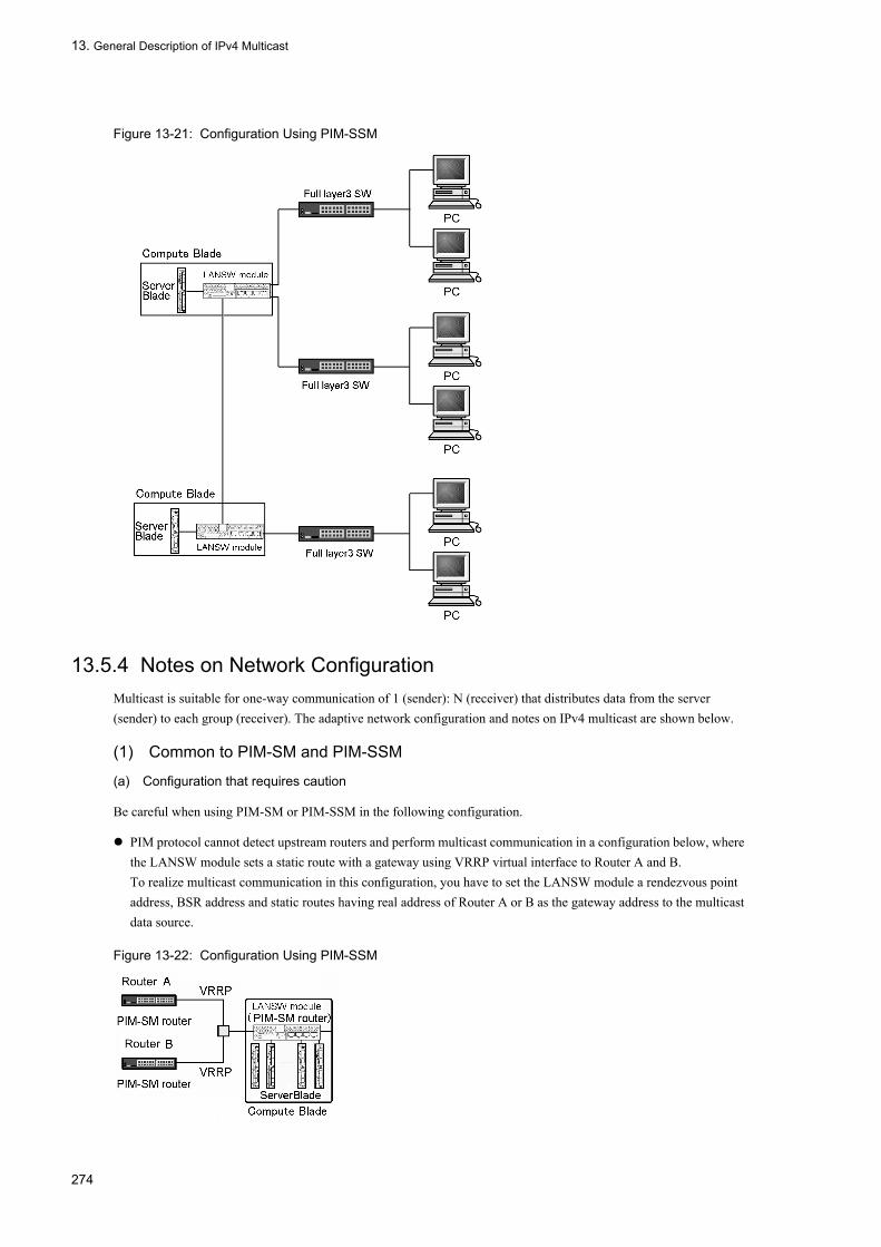
13. General Description of IPv4 Multicast
Figure 13-21: Configuration Using PIM-SSM
13.5.4 Notes on Network ConfigurationMulticast is suitable for one-way communication of 1 (sender): N (receiver) that distributes data from the server (sender) to each group (receiver). The adaptive network configuration and notes on IPv4 multicast are shown below.
(1) Common to PIM-SM and PIM-SSM
(a) Configuration that requires caution
Be careful when using PIM-SM or PIM-SSM in the following configuration.
PIM protocol cannot detect upstream routers and perform multicast communication in a configuration below, where the LANSW module sets a static route with a gateway using VRRP virtual interface to Router A and B.To realize multicast communication in this configuration, you have to set the LANSW module a rendezvous point address, BSR address and static routes having real address of Router A or B as the gateway address to the multicast data source.
Figure 13-22: Configuration Using PIM-SSM
274

13. General Description of IPv4 Multicast
(2) PIM-SM
(a) Recommended configuration
When configuring a PIM-SM network, a tree-type network configuration and redundant route are recommended. However, be very careful about the positioning of the rendezvous point. The recommended PIM-SM network configuration is shown in the figure below.
Figure 13-23: Recommended PIM-SM Network Configuration
(b) Unsuitable configuration
Do not use PIM-SM in the configuration described below.
Configuration in which the receiver is located between the sender and the rendezvous point:Packets are not efficiently relayed via a rendezvous point when the multicast communication of Group 1 is done from the server in the configuration described below.
275

13. General Description of IPv4 Multicast
Figure 13-24: Inappropriate configuration (when a recipient exists between a sender and a rendezvous point)
Configuration in which multiple PIM-SM routers operate in the same line as senderUnnecessary load is applied to the PIM-SM router that is not DR when the server sends multicast data in the configuration described below. This may greatly influence other functions of the LANSW module. Separate the lines.
Figure 13-25: Inappropriate configuration (when connecting a sender to multiple routers)
Configuration in which multiple PIM-SM routers operate in the same line as multicast group (receiver) and in which PIM-SM router not connected to rendezvous point existsThe shortest path may not be established between the sender and Group 1 when multicast communication for Group 1 is done in the configuration described below. Connect PIM-SM router 1 and PIM-SM router 2 to the rendezvous point.
Figure 13-26: Inappropriate configuration (when a router that is not connected to a rendezvous point exists)
(3) PIM-SSM
(a) Configuration that requires caution
The configuration described below requires caution.
Configuration in which multiple PIM-SSM routers operate in the same line as multicast group (receiver)When operating PIM-SSM in the configuration below using IGMPv2, set configuration command ip pim ssm and ip igmp ssm-map static of all routers on the same line.
276

13. General Description of IPv4 Multicast
Figure 13-27: Configuration requiring special attention (when connecting multiple routers to a host)
277

13. General Description of IPv4 Multicast
278
14. IPv4 Multicast Setting and Operation
14 IPv4 Multicast Setting and OperationThis chapter describes how to set and verify the IPv4 multicast configuration.
14.1 Configuration
14.2 Operation
279
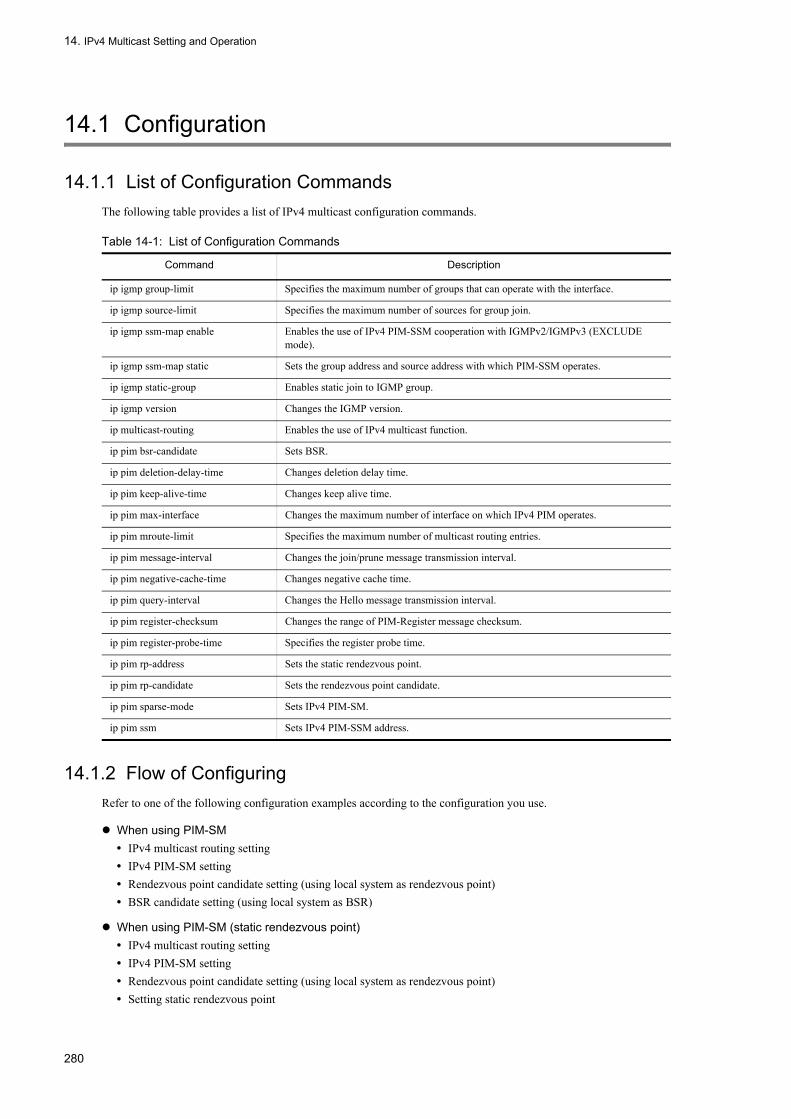
14. IPv4 Multicast Setting and Operation
14.1 Configuration
14.1.1 List of Configuration CommandsThe following table provides a list of IPv4 multicast configuration commands.
Table 14-1: List of Configuration Commands
14.1.2 Flow of ConfiguringRefer to one of the following configuration examples according to the configuration you use.
When using PIM-SM• IPv4 multicast routing setting• IPv4 PIM-SM setting• Rendezvous point candidate setting (using local system as rendezvous point)• BSR candidate setting (using local system as BSR)
When using PIM-SM (static rendezvous point)• IPv4 multicast routing setting• IPv4 PIM-SM setting• Rendezvous point candidate setting (using local system as rendezvous point)• Setting static rendezvous point
Command Description
ip igmp group-limit Specifies the maximum number of groups that can operate with the interface.
ip igmp source-limit Specifies the maximum number of sources for group join.
ip igmp ssm-map enable Enables the use of IPv4 PIM-SSM cooperation with IGMPv2/IGMPv3 (EXCLUDE mode).
ip igmp ssm-map static Sets the group address and source address with which PIM-SSM operates.
ip igmp static-group Enables static join to IGMP group.
ip igmp version Changes the IGMP version.
ip multicast-routing Enables the use of IPv4 multicast function.
ip pim bsr-candidate Sets BSR.
ip pim deletion-delay-time Changes deletion delay time.
ip pim keep-alive-time Changes keep alive time.
ip pim max-interface Changes the maximum number of interface on which IPv4 PIM operates.
ip pim mroute-limit Specifies the maximum number of multicast routing entries.
ip pim message-interval Changes the join/prune message transmission interval.
ip pim negative-cache-time Changes negative cache time.
ip pim query-interval Changes the Hello message transmission interval.
ip pim register-checksum Changes the range of PIM-Register message checksum.
ip pim register-probe-time Specifies the register probe time.
ip pim rp-address Sets the static rendezvous point.
ip pim rp-candidate Sets the rendezvous point candidate.
ip pim sparse-mode Sets IPv4 PIM-SM.
ip pim ssm Sets IPv4 PIM-SSM address.
280
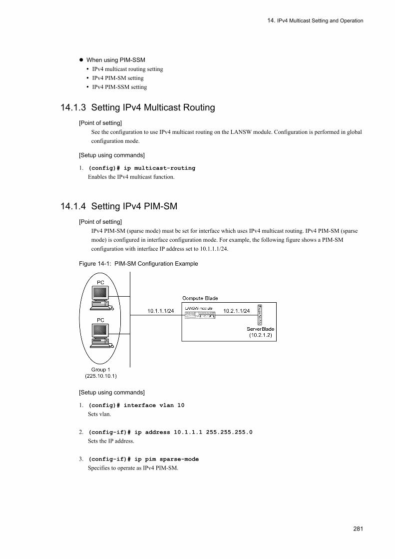
14. IPv4 Multicast Setting and Operation
When using PIM-SSM• IPv4 multicast routing setting• IPv4 PIM-SM setting• IPv4 PIM-SSM setting
14.1.3 Setting IPv4 Multicast Routing[Point of setting]
See the configuration to use IPv4 multicast routing on the LANSW module. Configuration is performed in global configuration mode.
[Setup using commands]
1. (config)# ip multicast-routing
Enables the IPv4 multicast function.
14.1.4 Setting IPv4 PIM-SM[Point of setting]
IPv4 PIM-SM (sparse mode) must be set for interface which uses IPv4 multicast routing. IPv4 PIM-SM (sparse mode) is configured in interface configuration mode. For example, the following figure shows a PIM-SM configuration with interface IP address set to 10.1.1.1/24.
Figure 14-1: PIM-SM Configuration Example
[Setup using commands]
1. (config)# interface vlan 10
Sets vlan.
2. (config-if)# ip address 10.1.1.1 255.255.255.0
Sets the IP address.
3. (config-if)# ip pim sparse-mode
Specifies to operate as IPv4 PIM-SM.
281

14. IPv4 Multicast Setting and Operation
14.1.5 Setting IPv4 PIM-SM Rendezvous Point Related Items
(1) Setting rendezvous point candidate
[Point of setting]When using the LANSW module as rendezvous point, set address to loopback 0 interface as rendezvous point and set the following in global configuration mode. An example of setting the managed multicast group address to 225.10.10.0/24 and the loopback address of the LANSW module to 10.10.10.10 is shown.
[Setup using commands]
1. (config)# interface loopback 0
(config-if)# ip address 10.10.10.10
(config-if)# exit
Sets the loopback address.
2. (config)# access-list 1 permit 225.10.10.0 0.0.0.255
(config)# exit
Creates an access list of managed multicast group addresses.
3. (config)# ip pim rp-candidate loopback 0 group-list 1
Sets the LANSW module as rendezvous point candidate (specifies access list created in step 2 as managed multicast group address).
(2) Setting BSR candidate
[Point of setting]When using the LANSW module as BSR candidate, set address to loopback 0 interface as BSR address and set the following in global configuration mode. An example of setting the loopback address of the LANSW module to 10.10.10.10 is shown.
[Setup using commands]
1. (config)# interface loopback 0
(config-if)# ip address 10.10.10.10
(config-if)# exit
Sets the loopback address.
2. (config)# ip pim bsr-candidate loopback 0
Sets the LANSW module as a BSR candidate.
14.1.6 Setting IPv4 PIM-SM BSR Candidate[Point of setting]
When the Switch is used as a BSR candidate, the address to the loopback 0 interface is set as the BSR address, and the following settings are specified in global configuration mode. In this example, 10.10.10.10 is used as the loopback address for the Switch.
[Setup using commands]
1. (config)# interface loopback 0
(config-if)# ip address 10.10.10.10
282
14. IPv4 Multicast Setting and Operation
(config-if)# exit
Sets the loopback address.
2. (config)# ip pim bsr-candidate loopback 0
Sets the LANSW module as a BSR candidate.
14.1.7 Setting IPv4 PIM-SM static rendezvous point[Point of setting]
The example below shows how to specify the static rendezvous point by using global configuration mode for the configuration. In this example, 10.10.10.1 is used as the switch address for the static rendezvous point.
[Setup using commands]
1. (config)# ip pim rp-address 10.10.10.1
Sets 10.10.10.1 as rendezvous point.
14.1.8 Setting IPv4 PIM-SSM
(1) Setting IPv4 PIM-SSM address
[Point of setting]Set the following in global configuration mode when using IPv4 PIM-SSM on the LANSW module. IPv4 PIM-SSM operates on the specified SSM address range on interface set with IPv4 PIM-SM with this setting. Only one SSM address can be set with the LANSW module. An example of setting the SSM address range on which PIM-SSM operates to default (232.0.0.0/8) is shown. Use ip pim ssm range when specifying the SSM address range.
[Setup using commands]
1. (config)# ip pim ssm default
Enables the IPv4 PIM-SSM (SSM address range is 232.0.0.0/8).
(2) Setting to enable IPv4 PIM-SSM with IGMPv2/IGMPv3 (EXCLUDE mode)
[Point of setting]PIM-SSM cooperation is disabled with IGMPv2/IGMPv3 (EXCLUDE mode) because the source address cannot be specified. The LANSW module performs cooperation to PIM-SSM by setting the group address and source address for PIM-SSM. The group address for PIM-SSM must be within the SSM address range specified with IPv4 PIM-SSM address configuration. A PIM-SSM configuration example with source address of server 1 set to 10.1.1.2 and server 2 set to 10.1.2.2 when group address is 232.10.10.1 and two servers are used is shown.
283
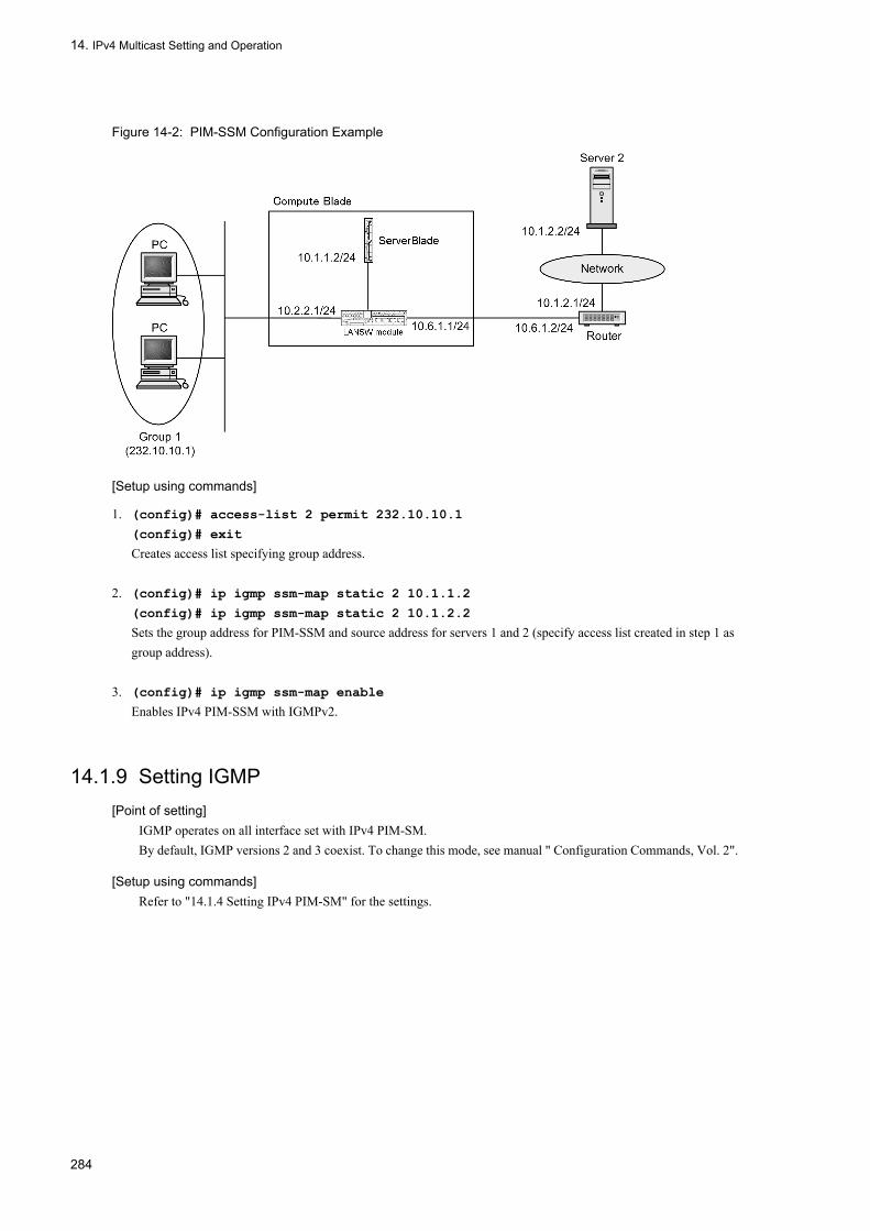
14. IPv4 Multicast Setting and Operation
Figure 14-2: PIM-SSM Configuration Example
[Setup using commands]
1. (config)# access-list 2 permit 232.10.10.1
(config)# exit
Creates access list specifying group address.
2. (config)# ip igmp ssm-map static 2 10.1.1.2
(config)# ip igmp ssm-map static 2 10.1.2.2
Sets the group address for PIM-SSM and source address for servers 1 and 2 (specify access list created in step 1 as group address).
3. (config)# ip igmp ssm-map enable
Enables IPv4 PIM-SSM with IGMPv2.
14.1.9 Setting IGMP[Point of setting]
IGMP operates on all interface set with IPv4 PIM-SM.By default, IGMP versions 2 and 3 coexist. To change this mode, see manual " Configuration Commands, Vol. 2".
[Setup using commands]Refer to "14.1.4 Setting IPv4 PIM-SM" for the settings.
284

14. IPv4 Multicast Setting and Operation
14.2 Operation
14.2.1 List of Operation CommandsThe following table provides a list of IPv4 multicast operation commands.
Table 14-2: List of Operation Commands
14.2.2 Checking IPv4 Multicast Group Address RouteUse the show ip mcache command to make sure the route to the destination address exists when using IPv4 multicast on the LANSW module. If the route does not exist or downstream is not correct, check "14.2.3 Checking IPv4 PIM-SM Information" and "14.2.4 Checking IGMP Information".
Figure 14-3: Execution Result of show ip mcache Command
> show ip mcacheDate 2005/08/01 15:20:00 UTCTotal: 1 routeGroup Source Uptime Expires Interface225.10.10.1 172.10.10.1 01:00 02:00 192.10.10.1 downstream: VLAN0001(192.20.10.1) VLAN0004(192.20.40.1)>
Command Description
show ip mcache Lists all multicast routes.
show ip mroute Displays PIM-SM/SSM multicast route information.
show ip pim interface Displays state of PIM-SM/SSM interface.
show ip pim neighbor Displays neighbor information of PIM-SM/SSM interface.
show ip pim mcache The PIM-SM or PIM-SSM multicast relay entry is displayed.
show ip pim bsr Displays PIM-SM/SSM BSR information.
show ip pim rp-mapping Displays PIM-SM rendezvous point information.
show ip pim rp-hash The PIM-SM rendezvous point information for each group is displayed.
show ip igmp interface Displays IGMP information.
show ip igmp group Displays IGMP information.
show ip rpf Displays RPF information of PIM.
show ip multicast statistics The statistic information about the IPv4 multicast is displayed.
clear ip multicast statistics The statistic information about the "clear ip multicast statistics IPv4" multicast is cleared.
restart ipv4-multicast Restarts the IPv4 multicast routing program (mrp).
dump protocols ipv4-multicast Obtains dump of event trace information and control table information.
erase protocol-dump ipv4-multicast Deletes the event trace information, control table information, and core file dump.
285
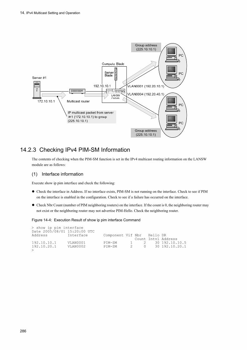
14. IPv4 Multicast Setting and Operation
14.2.3 Checking IPv4 PIM-SM InformationThe contents of checking when the PIM-SM function is set in the IPv4 multicast routing information on the LANSW module are as follows:
(1) Interface information
Execute show ip pim interface and check the following:
Check the interface in Address. If no interface exists, PIM-SM is not running on the interface. Check to see if PIM on the interface is enabled in the configuration. Check to see if a failure has occurred on the interface.
Check Nbr Count (number of PIM neighboring routers) on the interface. If the count is 0, the neighboring router may not exist or the neighboring router may not advertise PIM-Hello. Check the neighboring router.
Figure 14-4: Execution Result of show ip pim interface Command
> show ip pim interfaceDate 2005/08/01 15:20:00 UTCAddress Interface Component Vif Nbr Hello DR Count Intvl Address192.10.10.1 VLAN0001 PIM-SM 1 2 30 192.10.10.5192.10.20.1 VLAN0002 PIM-SM 2 0 30 192.10.20.1>
286

14. IPv4 Multicast Setting and Operation
(2) Neighbor information
Execute show ip pim neighbor and check the neighbor with the IP address in NeighborAddress on the interface. If no particular neighbor exists, the neighboring router may not advertise PIM-Hello. Check the neighboring router.
Figure 14-5: Execution Result of show ip pim neighbor Command
> show ip pim neighborDate 2005/08/01 15:20:00 UTCAddress Interface NeighborAddress Uptime Expires192.10.10.1 VLAN0001 192.10.10.3 00:05 01:40 192.10.10.5 00:10 01:35>
(3) Source route information
Execute the command "show ip rpf" and check the route information of the source.
287

14. IPv4 Multicast Setting and Operation
Figure 14-6: Execution Result of show ip rpf Command
> show ip rpf 192.5.5.100Date 2005/08/01 15:20:00 UTCRPF information for ? (192.5.5.100):If VLAN0001 NextHop 192.10.10.1 Proto 103
(4) PIM-SM BSR information
Execute show ip pim bsr and make sure that the BSR address is displayed. If "----" is displayed, the BSR may not advertise the Bootstrap message, or the BSR may not exist. Check the BSR. Note that PIM-SSM does not use BSR.
Figure 14-7: Execution Result of show ip pim bsr Command
> show ip pim bsrDate 2005/08/01 15:20:00 UTCStatus : Not candidate Bootstrap RouterBSR Address : 192.10.10.10 Priority: 100 Hash mask length: 30 Uptime : 03:00 Bootstrap Timeout : 130 seconds>
(5) PIM-SM rendezvous point information
Execute show ip pim rp-mapping and make sure that C-RP Address is displayed for the IPv4 multicast group address. Otherwise, the BSR may not advertise the Bootstrap message or the rendezvous point or BSR may not exist. Check the rendezvous point and BSR. Note that PIM-SSM does not use rendezvous point.
Figure 14-8: Execution Result of show ip pim rp-mapping Command
> show ip pim rp-mappingDate 2005/08/01 15:20:00 UTCStatus : Not candidate Rendezvous PointTotal: 2 routes, 2 groups, 1 RPGroup/masklen C-RP Address Pri Uptime Expires224.100.100.0/24 192.1.1.1 100 02:00 02:30224.100.200.0/24 192.1.1.1 100 02:00 02:30>
(6) PIM-SM routing information
Execute the command "show ip mroute" and check to see if the route to the destination address exists. If the (S,G) entry does not appear, check to see if the (*,G) entry exists. If (*,G) does not exist and in-coming, downstream is not correct, check the neighboring router. PIM-SSM does not use (*,G) (which does not appear).
288
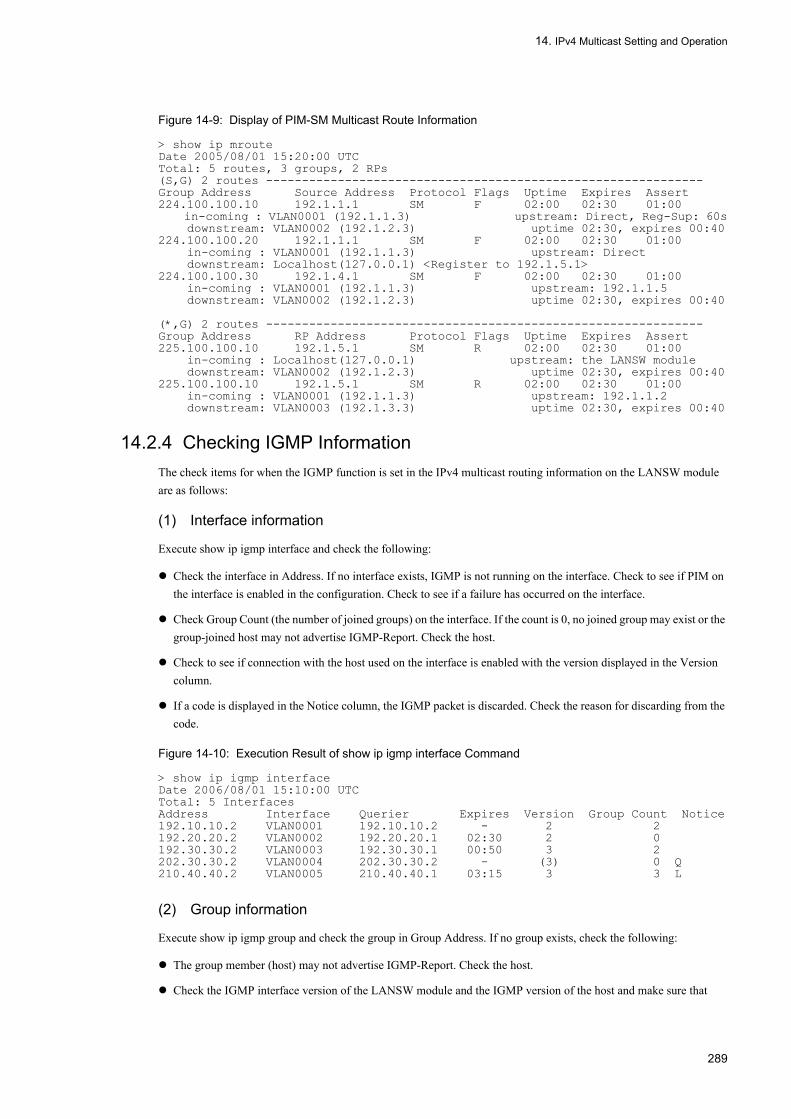
14. IPv4 Multicast Setting and Operation
Figure 14-9: Display of PIM-SM Multicast Route Information
> show ip mrouteDate 2005/08/01 15:20:00 UTCTotal: 5 routes, 3 groups, 2 RPs(S,G) 2 routes -------------------------------------------------------------Group Address Source Address Protocol Flags Uptime Expires Assert224.100.100.10 192.1.1.1 SM F 02:00 02:30 01:00 in-coming : VLAN0001 (192.1.1.3) upstream: Direct, Reg-Sup: 60s downstream: VLAN0002 (192.1.2.3) uptime 02:30, expires 00:40224.100.100.20 192.1.1.1 SM F 02:00 02:30 01:00 in-coming : VLAN0001 (192.1.1.3) upstream: Direct downstream: Localhost(127.0.0.1) <Register to 192.1.5.1>224.100.100.30 192.1.4.1 SM F 02:00 02:30 01:00 in-coming : VLAN0001 (192.1.1.3) upstream: 192.1.1.5 downstream: VLAN0002 (192.1.2.3) uptime 02:30, expires 00:40 (*,G) 2 routes -------------------------------------------------------------Group Address RP Address Protocol Flags Uptime Expires Assert225.100.100.10 192.1.5.1 SM R 02:00 02:30 01:00 in-coming : Localhost(127.0.0.1) upstream: the LANSW module downstream: VLAN0002 (192.1.2.3) uptime 02:30, expires 00:40225.100.100.10 192.1.5.1 SM R 02:00 02:30 01:00 in-coming : VLAN0001 (192.1.1.3) upstream: 192.1.1.2 downstream: VLAN0003 (192.1.3.3) uptime 02:30, expires 00:40
14.2.4 Checking IGMP InformationThe check items for when the IGMP function is set in the IPv4 multicast routing information on the LANSW module are as follows:
(1) Interface information
Execute show ip igmp interface and check the following:
Check the interface in Address. If no interface exists, IGMP is not running on the interface. Check to see if PIM on the interface is enabled in the configuration. Check to see if a failure has occurred on the interface.
Check Group Count (the number of joined groups) on the interface. If the count is 0, no joined group may exist or the group-joined host may not advertise IGMP-Report. Check the host.
Check to see if connection with the host used on the interface is enabled with the version displayed in the Version column.
If a code is displayed in the Notice column, the IGMP packet is discarded. Check the reason for discarding from the code.
Figure 14-10: Execution Result of show ip igmp interface Command
> show ip igmp interfaceDate 2006/08/01 15:10:00 UTCTotal: 5 InterfacesAddress Interface Querier Expires Version Group Count Notice192.10.10.2 VLAN0001 192.10.10.2 - 2 2192.20.20.2 VLAN0002 192.20.20.1 02:30 2 0192.30.30.2 VLAN0003 192.30.30.1 00:50 3 2202.30.30.2 VLAN0004 202.30.30.2 - (3) 0 Q210.40.40.2 VLAN0005 210.40.40.1 03:15 3 3 L
(2) Group information
Execute show ip igmp group and check the group in Group Address. If no group exists, check the following:
The group member (host) may not advertise IGMP-Report. Check the host.
Check the IGMP interface version of the LANSW module and the IGMP version of the host and make sure that
289

14. IPv4 Multicast Setting and Operation
connection to the host is possible.
If the host ignores IGMPv3 Query, IGMPv3 cannot be used. Set the IGMP version of the corresponding interface to 2.
Figure 14-11: Execution Result of show ip igmp groups Command
> show ip igmp groups briefDate 2006/08/01 15:10:00 UTCTotal: 7 groupsGroup Address Interface Version Mode Source Count224.1.1.1 VLAN0001 2 EXCLUDE 0232.1.1.2 VLAN0001 2 EXCLUDE 2234.1.1.1 VLAN0003 2 EXCLUDE 1234.1.1.2 VLAN0003 3 INCLUDE 1232.1.1.1 VLAN0004 3 INCLUDE 1232.1.1.3 VLAN0004 3 INCLUDE 2235.1.1.1 VLAN0004 3 EXCLUDE 3
290
15. General Description of IPv6/NDP/ICMPv6
Part 3 IPv6 Packet Relay
15General Description of IPv6/NDP/ICMPv6IPv6 network has various functions such as communications function, IP packet relay function, filtering function, and load balancing function. This chapter describes the IPv6 packet relay.
15.1 Addressing
15.2 IPv6 Layer Function
15.3 Communications Function
15.4 Relay Function
15.5 Notes on Using IPv6
291

15. General Description of IPv6/NDP/ICMPv6
15.1 Addressing
IPv6 has the following advantages over IPv4.
• The address structure is extended.The address length is extended from 32 bits to 128 bits. Therefore, the number of addresses that can be assigned to nodes becomes almost infinite. This solves the problem of insufficient IP address which IPv4 has. Moreover, the number of levels in address structural hierarchy increases, enabling new addresses to be defined.
• The header format is simplified.Compared to IPv4, the header field is simplified, reducing protocol processing overhead.
• The extended and option headers are enhanced.It is easy to improve transfer efficiency and alleviate option length limitation as well as to extend options.
• The flow label can be set.A label can be attached that identifies a specific traffic flow.
An outline of addressing of the IPv6 network used in the LANSW module, is shown below.
15.1.1 IPv6 AddressThree types of address formats are defined for IPv6 addresses: unicast, anycast, and multicast.
(1) Unicast address
Address indicating a single interface. Packets whose end address is a unicast address are delivered to the interface indicated by that address. The figure below shows unicast address communication.
Figure 15-1: Unicast Address Communication
(2) Anycast address
Address indicating a collection of interfaces. Packets whose end address is an anycast address are delivered to the nearest interface among the interface collection, measured using the routing protocol. In the meantime, the System supports no anycast addresses. The figure below shows anycast address communication.
292

15. General Description of IPv6/NDP/ICMPv6
Figure 15-2: Anycast Address Communication
(3) Multicast address
Address indicating a collection of interfaces. Packets whose end address is a multicast address are delivered to all the interfaces among the interface collection indicated by that address. The figure below shows multicast address communication.
Figure 15-3: Multicast Address Communication
15.1.2 Address NotationIPv6 addresses are 128 bits long. The actual notation method is shown below.
293

15. General Description of IPv6/NDP/ICMPv6
• Use a format where every 16-bit hexadecimal is delimited by a colon ":".Example: 3ffe:0501:0811:ff02:0000:08ff:fe8b:3090
• "0" at the beginning of hexadecimal can be omitted.Example: 3ffe:501:811:ff02:0:8ff:fe8b:3090
• Consecutive "0s" can be replaced by 2 colons "::". However, such a replacement is defined to be possible only once for each address notation.Example: Replacement method for the IPv6 address below fe80:0000:0000:0000:0000:0000:0000:3090 → fe80::3090Example: "::" at two or more places is prohibited. fe80:0000:0000:0000:0000:0000:0000:3090 → fe80::0::3090
• The address and the prefix length can be specified in the following format:• IPv6 address/prefix length• IPv6 address prefixlen prefix length
The prefix length specifies in decimal which bits from the leftmost bit of the address are the prefix.
15.1.3 Address Format Prefix128-bit IPv6 address is divided into multiple subfields. The start bit has a role of identifying the type of the IPv6 address, being called the address format prefix. The following figure shows the IP address format prefix.
Figure 15-4: Address Format Prefix
Also, the type of the address format prefix is shown in the following table.
Table 15-1: Type of Address Format Prefix
Prefix (in Binary) Assignment
0000 0000 Reserved
0000 0001 Not assigned
0000 001 Reserved for NSAP allocation
0000 010 Reserved for IPX allocation
0000 011 Not assigned
0000 1 Not assigned
0001 Not assigned
001 Aggregatable global unicast address
010 Not assigned
011 Not assigned
100 Not assigned
101 Not assigned
110 Not assigned
1110 Not assigned
1111 0 Not assigned
1111 10 Not assigned
294
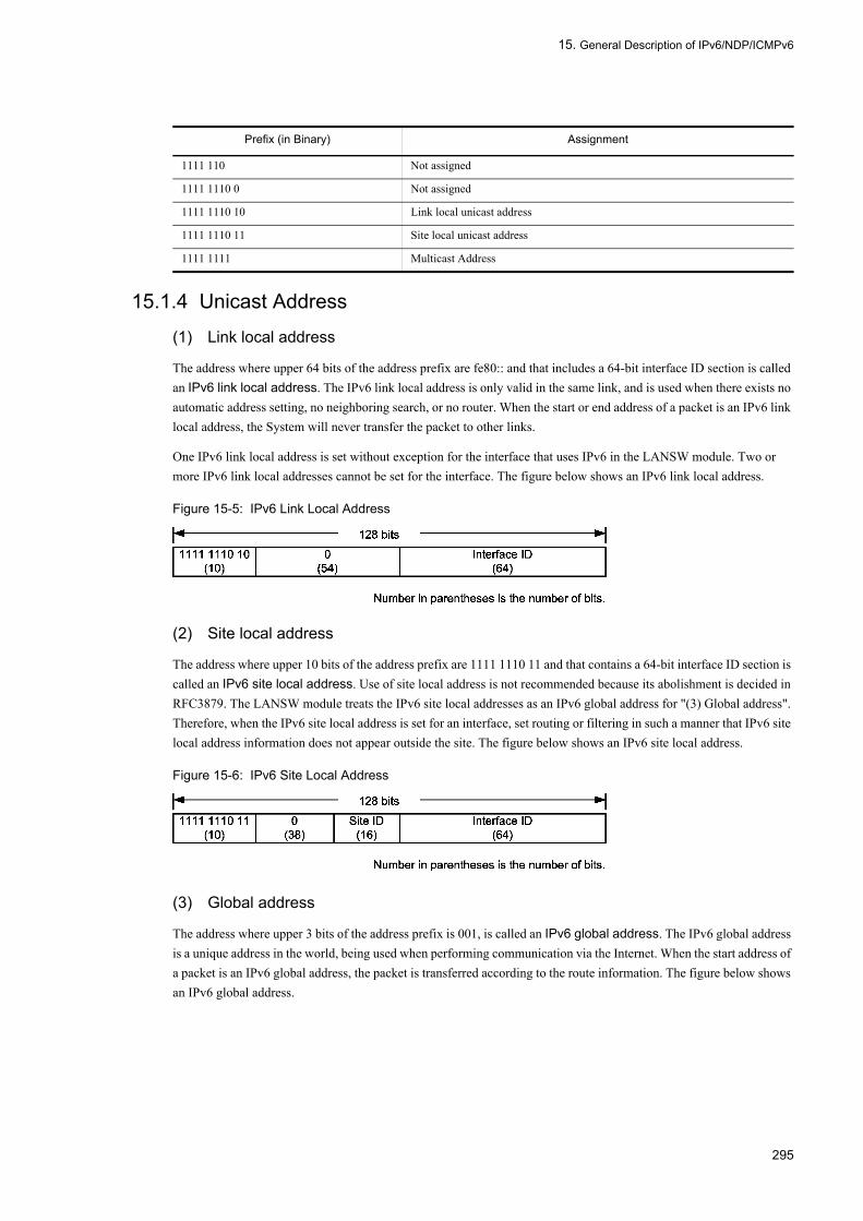
15. General Description of IPv6/NDP/ICMPv6
15.1.4 Unicast Address
(1) Link local address
The address where upper 64 bits of the address prefix are fe80:: and that includes a 64-bit interface ID section is called an IPv6 link local address. The IPv6 link local address is only valid in the same link, and is used when there exists no automatic address setting, no neighboring search, or no router. When the start or end address of a packet is an IPv6 link local address, the System will never transfer the packet to other links.
One IPv6 link local address is set without exception for the interface that uses IPv6 in the LANSW module. Two or more IPv6 link local addresses cannot be set for the interface. The figure below shows an IPv6 link local address.
Figure 15-5: IPv6 Link Local Address
(2) Site local address
The address where upper 10 bits of the address prefix are 1111 1110 11 and that contains a 64-bit interface ID section is called an IPv6 site local address. Use of site local address is not recommended because its abolishment is decided in RFC3879. The LANSW module treats the IPv6 site local addresses as an IPv6 global address for "(3) Global address". Therefore, when the IPv6 site local address is set for an interface, set routing or filtering in such a manner that IPv6 site local address information does not appear outside the site. The figure below shows an IPv6 site local address.
Figure 15-6: IPv6 Site Local Address
(3) Global address
The address where upper 3 bits of the address prefix is 001, is called an IPv6 global address. The IPv6 global address is a unique address in the world, being used when performing communication via the Internet. When the start address of a packet is an IPv6 global address, the packet is transferred according to the route information. The figure below shows an IPv6 global address.
1111 110 Not assigned
1111 1110 0 Not assigned
1111 1110 10 Link local unicast address
1111 1110 11 Site local unicast address
1111 1111 Multicast Address
Prefix (in Binary) Assignment
295

15. General Description of IPv6/NDP/ICMPv6
Figure 15-7: IPv6 Global Address
(4) Unspecified address
An address whose all bits are 0 (that is, an address 0:0:0:0:0:0:0:0 (0::0 or ::)) is defined as an unspecified address. The unspecified address indicates that no address exists in an interface. The unspecified address is used when starting connecting a node to which no address is assigned. The unspecified address cannot be intentionally assigned to a node. The figure below shows an unspecified address.
Figure 15-8: Unspecified Address
(5) Loopback address
Address 0:0:0:0:0:0:0:1 (0::1 or ::1) is defined as a loopback address. The loopback address is used as the destination address of a packet when communicating to the local node. It cannot be assigned to an interface. Also, an IPv6 packet whose end address is a loopback address is prohibited to be sent outside the node or to be transferred using a router. The following figure shows a loopback address.
Figure 15-9: Loopback Address
(6) IPv4-compatible address
The IPv4-compatible IPv6 address is an address used to communicate in a network where the route between two IPv6 nodes is controlled via IPv4. It is a special unicast address containing an IPv4 address in lower-order 32 bits, and is used when devices connected to an IPv4 network communicate to each other. The prefix is 96 bits long, which are all 0's. The figure below shows an IPv4-compatible address.
Figure 15-10: IPv4-compatible Address
(7) IPv4-mapped address
The IPv4-mapped IPv6 address is used in an IPv4 dedicated node not supporting IPv6. When communicating to a host supporting only IPv4, an IPv6 host uses an IPv4-mapped IPv4 address. The prefix is 96 bits long; 0 for upper 80 bits is followed by 1 for lower 16 bits. The figure below shows an IPv4-mapped address.
296
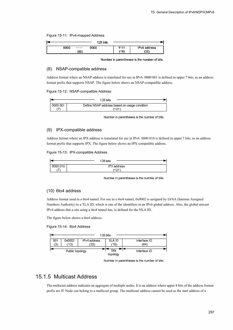
15. General Description of IPv6/NDP/ICMPv6
Figure 15-11: IPv4-mapped Address
(8) NSAP-compatible address
Address format where an NSAP address is translated for use in IPv6. 0000 001 is defined in upper 7 bits, as an address format prefix that supports NSAP. The figure below shows an NSAP-compatible address.
Figure 15-12: NSAP-compatible Address
(9) IPX-compatible address
Address format where an IPX address is translated for use in IPv6. 0000 010 is defined in upper 7 bits, as an address format prefix that supports IPX. The figure below shows an IPX-compatible address.
Figure 15-13: IPX-compatible Address
(10) 6to4 address
Address format used in a 6to4 tunnel. For use in a 6to4 tunnel, 0x0002 is assigned by IANA (Internet Assigned Numbers Authority) to a TLA ID, which is one of the identifiers in an IPv6 global address. Also, the global unicast IPv4 address that a site using a 6to4 tunnel has, is defined for the NLA ID.
The figure below shows a 6to4 address.
Figure 15-14: 6to4 Address
15.1.5 Multicast AddressThe multicast address indicates an aggregate of multiple nodes. It is an address where upper 8 bits of the address format prefix are ff. Node can belong to a multicast group. The multicast address cannot be used as the start address of a
297
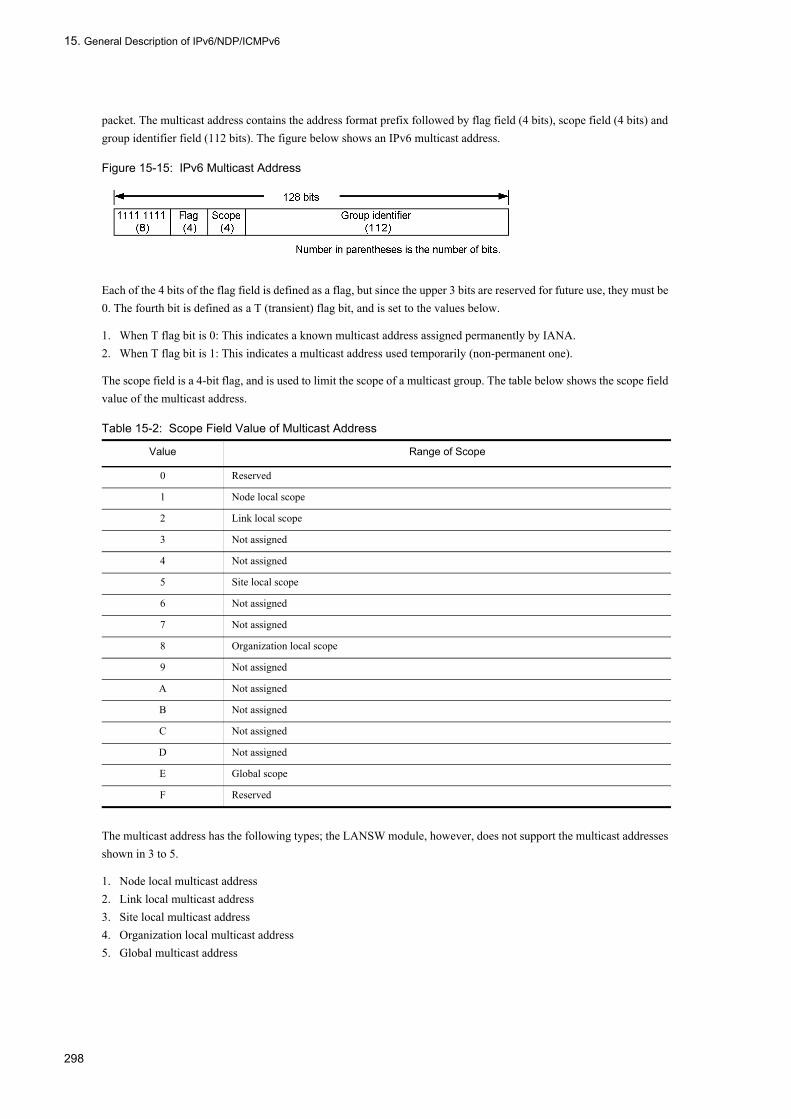
15. General Description of IPv6/NDP/ICMPv6
packet. The multicast address contains the address format prefix followed by flag field (4 bits), scope field (4 bits) and group identifier field (112 bits). The figure below shows an IPv6 multicast address.
Figure 15-15: IPv6 Multicast Address
Each of the 4 bits of the flag field is defined as a flag, but since the upper 3 bits are reserved for future use, they must be 0. The fourth bit is defined as a T (transient) flag bit, and is set to the values below.
1. When T flag bit is 0: This indicates a known multicast address assigned permanently by IANA.2. When T flag bit is 1: This indicates a multicast address used temporarily (non-permanent one).
The scope field is a 4-bit flag, and is used to limit the scope of a multicast group. The table below shows the scope field value of the multicast address.
Table 15-2: Scope Field Value of Multicast Address
The multicast address has the following types; the LANSW module, however, does not support the multicast addresses shown in 3 to 5.
1. Node local multicast address2. Link local multicast address3. Site local multicast address4. Organization local multicast address5. Global multicast address
Value Range of Scope
0 Reserved
1 Node local scope
2 Link local scope
3 Not assigned
4 Not assigned
5 Site local scope
6 Not assigned
7 Not assigned
8 Organization local scope
9 Not assigned
A Not assigned
B Not assigned
C Not assigned
D Not assigned
E Global scope
F Reserved
298
15. General Description of IPv6/NDP/ICMPv6
(1) Reserved multicast address
The following multicast addresses are reserved beforehand; they cannot be assigned to any multicast group.
1. ff00:0:0:0:0:0:0:02. ff01:0:0:0:0:0:0:03. ff02:0:0:0:0:0:0:04. ff03:0:0:0:0:0:0:05. ff04:0:0:0:0:0:0:06. ff05:0:0:0:0:0:0:07. ff06:0:0:0:0:0:0:08. ff07:0:0:0:0:0:0:09. ff08:0:0:0:0:0:0:010. ff09:0:0:0:0:0:0:011. ff0a:0:0:0:0:0:0:012. ff0b:0:0:0:0:0:0:013. ff0c:0:0:0:0:0:0:014. ff0d:0:0:0:0:0:0:015. ff0e:0:0:0:0:0:0:016. ff0f:0:0:0:0:0:0:0
(2) Total node address
The total node address indicates the aggregate of all IPv6 nodes in the specified scope. Packets having this address as the end address are received by all the nodes in the specified scope. Type of total node address is shown below.
1. ff01:0:0:0:0:0:0:1 Node local/total node address2. ff02:0:0:0:0:0:0:1 Link local/total node address
(3) Total router address
The total router address indicates the aggregate of all IPv6 routers in the specified scope. Packets having this address as an end address are received by all the routers in the specified scope. Type of total router address is shown below.
1. ff01:0:0:0:0:0:0:2 Node local/total router address2. ff02:0:0:0:0:0:0:2 Link local/total router address3. ff05:0:0:0:0:0:0:2 Site local/total router address
(4) Request node address
The request node address is translated from the unicast and anycast addresses of a node. It is an address obtained when the lower-order 24 bits of the request node address (unicast or anycast address) are added to a 104-bit prefix (ff02:0:0:0:0:1:ff00::/104). The range of the request node address is as follows:
ff02:0:0:0:0:1:ff00:0000 to ff02:0:0:0:0:1:ffff:ffff
When IPv6 addresses whose several upper bits differ are generated because the upper prefix differs for each aggregated provider, these addresses are the same request node address. This can reduce the number of multicast addresses which a node must join.
15.1.6 Handling of IPv6 Addresses Used in the LANSW module
(1) Supported addresses
The addresses below can be used as the IPv6 addresses assigned to the interface of the LANSW module.
299

15. General Description of IPv6/NDP/ICMPv6
1. Global unicast address2. Link local unicast address
Also, the IPv6 addresses below can be set, but they are handled as equivalent to global unicast addresses.
1. Site local unicast address2. Anycast address3. Unicast address to which no address format prefix is assigned4. NSAP-compatible address5. IPX-compatible address
(2) Unsupported addresses
The IPv6 addresses in the format below cannot be assigned to an interface.
1. Multicast address2. Undefined address3. Loopback address4. IPv4-compatible address5. IPv4-mapped address6. Address where upper 10 bits are 1111 1110 10 and all bits from bit 11 to bit 64 are not 07. Address where upper 10 bits are 1111 1111 10 and where the subsequent bits are all 08. Address where the interface ID section is all 0 when the prefix length is not 64 bits.
(3) Automatic address generation when interface ID is omitted
In the LANSW module, the prefix format where the interface ID is omitted can be specified when setting IPv6 addresses for an interface. When the prefix format is specified and the prefix is 64 bits long or omitted, the interface ID can be automatically generated on the System side from the MAC address. The figure below shows an example of automatic address generation.
Figure 15-16: Example of Automatic Address Generation
When an IPv6 address other than the link local address is specified for an interface, and the link local address does not exist in the relevant interface, a link local unicast address is automatically generated and set. Moreover, only a link local unicast address can be set to an interface by automatic generation.
(4) Available conditions for prefix length
In the LANSW module, interface ID is automatically generated when it is not specified. Since the length of the interface ID is fixed at 64 bits, when other than 64 or omission is specified for the prefix length, the interface ID is not automatically generated; instead the input prefix is determined as an address. Therefore, no addressing can be set that causes all the lower-order 64 bits to be set to 0. The table below shows the available conditions for prefix length.
300

15. General Description of IPv6/NDP/ICMPv6
Table 15-3: Conditions Available for Prefix Length
(Legend) Y: Setting allowed N: Setting not allowed
15.1.7 Stateless Address Autoconfiguration Function This function automatically creates IPv6 link local addresses in a system, and notifies from a router the information that is required when the host automatically creates IPv6 addresses. The LANSW module supports IPv6 stateless address autoconfiguration (conforming to RFC2462).
Addressing Format Setting Allowed
Description
3ffe:501::/1 to 3ffe:501::/31 Y Setting is allowed because the specified prefix length is shorter than the prefix and therefore not all bits of the interface ID section are set to 0.
3ffe:501::/32 to 3ffe:501::/63 N Setting is not allowed because the specified prefix length is longer than the prefix and therefore all bits of the interface ID section are set to 0.
3ffe:501::/64 or 3ffe:501:: Y Setting is allowed because when the prefix length is 64 or not specified and the interface ID section is omitted, the interface ID is automatically generated in the System.
301

15. General Description of IPv6/NDP/ICMPv6
15.2 IPv6 Layer Function
15.2.1 Relay FunctionThe LANSW module relays the received IPv6 packets according to the routing table. This relaying process can be divided into the following three major functions: The figure below provides a general description of the IPv6 Routing Function.
Figure 15-17: Outline of IPv6 Routing Function
• Communications functionThis function is used for transmission and reception of IPv6 layer.
• Relay functionThis function relays IPv6 packets according to the routing table.
• Route control functionThis function sends and receives path information, determines the relay path, or creates the routing table.
15.2.2 Unit of IPv6 Address AssignmentThe LANSW module assigns IPv6 address to VLAN. In IPv6, multiple IPv6 addresses can be set for one interface, and IPv6 link local addresses are automatically assigned to the VLAN for which IPv6 addresses are set. However, this does not apply when link local addresses are set using configuration.
302

15. General Description of IPv6/NDP/ICMPv6
15.3 Communications Function
This section provides an explanation of communications protocols that can be used with IPv6. The following communications protocols can be used with IPv6.
• IPv6• ICMPv6• NDP
15.3.1 Internet Protocol Version 6 (IPv6)
(1) IPv6 packet format
The format and set value of IPv6 packets that the LANSW module sends conform to RFC2460. The IPv6 packet format is shown in the figure below.
Figure 15-18: IPv6 Packet Format
(2) Check of IPv6 packet header for validity
In IPv6, the 40-octet length header contains eight fields and two addresses. The IPv6 format is shown in the figure below.
Figure 15-19: IPv6 Header Format
303

15. General Description of IPv6/NDP/ICMPv6
The IPv6 packet header is checked for validity during IPv6 packet reception. The figure below shows the check of an IPv6 packet header.
Table 15-4: Check Items of IPv6 Packet Header
(Legend) -: Not applicable* Sends an ICMPv6 Time Exceeded message.
(3) IPv6 extended header support specification
The IPv6 extended header that the LANSW module supports is shown in the table below.
Table 15-5: Items of IPv6 Extended Header
(Legend) Y: Supported N: Not supported -: Without header processing
*1If any of the following conditions apply to the packet received by the LANSW module, the packet will be discarded.
IPv6 PacketHeader Field
Check Item Invalid Packet Processing
ICMPv6 Transmission during
Packet Discard
Version If version = 6 Discarded N
Traffic class Not checked - -
Flow label Not checked - -
Pay load length Compared with the packet length.Packet length < Payload length.
Discarded N
Compared with the packet length.Packet length ≥ Pay load length
Deletes the rear of a packet by payload length.
N
Next header Not checked - -
Hop limit For the hop limit of the received packets addressed to a source system, not checked.
- -
Hop limit of the packets to be forwardedThe hop limit must be -1 > 0.
Discarded Sent*
Source address The conditions below must be satisfied.1. This address is not a link local address.2. This address is not a multicast address.
Discarded N
Destination address The conditions below must be satisfied.1. This address is not a loopback address.2. The interface ID block is not "0" (not
including the undefined address).
Discarded N
IPv6 Extended Header Classified IPv6 Packets
Packets Originating from the LANSW
module
Packets Terminating to the LANSW
module*1
Packets Relayed by the LANSW module
Hop-by-Hop Options Header Y Y Y*2
Routing Header Y Y -
Fragment Header Y Y -
Authentication Header N N -
Encapsulating Security Payload Header N N -
Destination Options Header Y Y -
304

15. General Description of IPv6/NDP/ICMPv6
- Packet set with more than nine expansion headers.- Packet set with more than nine options in one expansion header.
*2If the following condition applies to a packet relayed by the LANSW module, the packet will be discarded.- Packet set with more than nine options in the hop-by-hop options header.
15.3.2 ICMPv6The format and set value of an ICMPv6 message that the LANSW module sends conform to RFC2463. The table below shows the support specifications of an ICMPv6 message.
Table 15-6: Support Specifications of ICMPv6 Message
(Legend) Y: Supported -: Note applicable
(1) Specifications of ICMPv6 redirect packet transmission
ICMPv6 Redirect packets are transmitted when the conditions below are satisfied.
• The packet source and next hop router are located in the same link.• The received packets are IPv6 packets other than ICMPv6.
ICMPv6 Message Support
Type Value (in Decimal)
Code (Detail Type) Value (in Decimal)
Destination Unreachable 1 no route to destination 0 Y
communication with destination administratively prohibited
1 Y
beyond scope of source address 2 Y
address unreachable 3 Y
port unreachable 4 Y
Packet Too Big 2 - 0 Y
Time Exceeded 3 hop limit exceeded in transit 0 Y
fragment reassembly time exceeded 1 Y
Parameter Problem 4 erroneous header field encountered 0 Y
unrecognized Next Header type encountered 1 Y
unrecognized IPv6 option encountered 2 Y
Echo Request 128 - 0 Y
Echo Reply 129 - 0 Y
Multicast Listener Query 130 - 0 Y
Multicast Listener Report 131 - 0 Y
Multicast Listener Done 132 - 0 Y
Router Solicitation 133 - 0 Y
Router Advertisement 134 - 0 Y
Neighbor Solicitation 135 - 0 Y
Neighbor Advertisement 136 - 0 Y
Redirect 137 - 0 Y
305

15. General Description of IPv6/NDP/ICMPv6
(2) Specifications of ICMPv6 Time Exceeded packet transmission
ICMPv6 Time Exceeded packets are transmitted when the conditions below are satisfied.
• The Hoplimit of the received IPv6 packets to be forwarded is "1".• The received packets are IPv6 packets other than ICMPv6.
15.3.3 NDPThe format and set value of an NDP frame that the LANSW module sends conform to RFC2461.
(1) ProxyNDP
The LANSW module can operate ProxyNDP using all interfaces connected to Ethernet. The LANSW module sends an NDP adjacent advertisement message instead of a destination protocol address when it receives an NDP adjacent request message that satisfies the conditions below.
• The destination protocol address of an NDP adjacent request message is not a multicast address or any-cast address.• The network numbers of the source protocol address and destination protocol address in an NDP adjacent request
message are equal.• The destination protocol address in an NDP adjacent request message is located in a routing table and can be reached.
(2) Conditions for deleting an NDP entry
If any one of the following conditions is met, the subject NDP entry is deleted. However, the static NDP entry having been set by configuration will not be deleted.
• When ten minutes has elapsed after communication with the IPv6 address corresponding to the NDP entry has been stopped.
• If no reachable status is available when communication with the IPv6 address in which the status corresponds to the NDP entry of the stale is resumed.
• All NDP entry data existing in the subject interface when the interface status goes down.
(3) Setting of static NDP information
To connect products that have no NDP protocol, the MAC addresses of an Ethernet and gigabit Ethernet and their corresponding IPv6 addresses (static NDP information) can be set by configuration.
(4) Reference of NDP information
NDP information can be referenced from the operating terminal using the show ipv6 neighbors command. The IPv6 address of the relevant interface and its corresponding MAC address can be found in the NDP information.
306
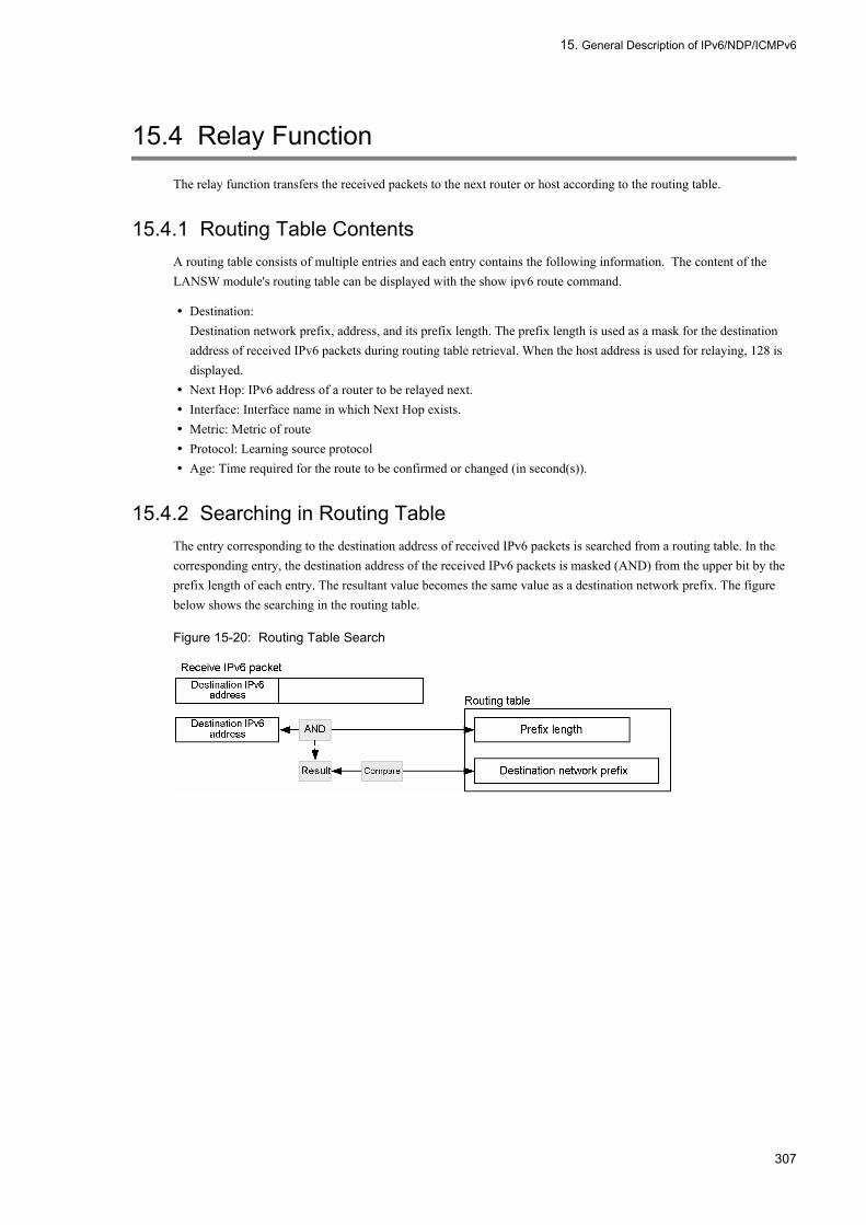
15. General Description of IPv6/NDP/ICMPv6
15.4 Relay Function
The relay function transfers the received packets to the next router or host according to the routing table.
15.4.1 Routing Table ContentsA routing table consists of multiple entries and each entry contains the following information. The content of the LANSW module's routing table can be displayed with the show ipv6 route command.
• Destination:Destination network prefix, address, and its prefix length. The prefix length is used as a mask for the destination address of received IPv6 packets during routing table retrieval. When the host address is used for relaying, 128 is displayed.
• Next Hop: IPv6 address of a router to be relayed next.• Interface: Interface name in which Next Hop exists.• Metric: Metric of route• Protocol: Learning source protocol• Age: Time required for the route to be confirmed or changed (in second(s)).
15.4.2 Searching in Routing TableThe entry corresponding to the destination address of received IPv6 packets is searched from a routing table. In the corresponding entry, the destination address of the received IPv6 packets is masked (AND) from the upper bit by the prefix length of each entry. The resultant value becomes the same value as a destination network prefix. The figure below shows the searching in the routing table.
Figure 15-20: Routing Table Search
307
15. General Description of IPv6/NDP/ICMPv6
15.5 Notes on Using IPv6
(1) Change in MTU length of IPv6 relay line
The minimum packet length of IPv6 is prescribed to be 1280 bytes or more (RFC2460). Therefore, IPv6 communication is not possible when MTU length is set to less than 1280 bytes. Set the MTU length of an interface, which performs IPv6 communication, to more than 1280 bytes for use.
(2) Setting of global addresses to the interface
When setting a global address to the interface, make the prefix and prefix count for the interface on the same link the same for all systems. When that condition is not met, communication to prefixes for the interface that do not exist in the LANSW module. cannot be performed.
(3) IPv6 address duplication
IPv6 has DAD (Duplicate Address Detection) function stated in RFC 2462. If duplication of IPv6 address is found by DAD, the address cannot be used for communication. If "duplicated" appears next to the IPv6 address by executing the commands show ipv6 interface or show ip-dual interface, the address is overlapping with another system's address. In this case, take the following actions:
• When another system's IPv6 address is wrongChange another system's IPv6 address first of all, and then delete the IPv6 address of the LANSW module and set it again, or simply restart the LANSW module.
• When the LANSW module's IPv6 address is wrongDelete the overlapping IPv6 address from the configuration, and set a correct address.
• Overlapping of automatically created IPv6 addressesThis indicates a looped configuration on VLAN interface or a terminal spoofing the LANSW module's IPv6 address. At first eliminate the root cause and execute the no ipv6 enable command, and then execute the ipv6 enable command again.
(4) Notes on static NDP
If static NDP that overlaps the IPv6 address set for the interface on the LANSW module is set, system behavior becomes unstable (e.g. communication failure). Therefore, the LANSW module checks for duplication between the interface IPv6 address and static NDP during configuration input. However, duplication is not checked for the IPv6 addresses below.
• Link local address (automatically created or manually set)• Global address that is automatically created when the interface ID is omitted
Therefore, do not set the same static NDP as one of these IPv6 addresses set for the interface. If static NDP is incorrectly set, delete the static NDP and restart VLAN of the interface.
308

16. Configuration and Operation of IPv6/NDP/ICMPv6
16Configuration and Operation of IPv6/NDP/ICMPv6This chapter describes how to set and verify the IPv6 network configuration.
16.1 Configuration
16.2 Operation
309

16. Configuration and Operation of IPv6/NDP/ICMPv6
16.1 Configuration
16.1.1 List of Configuration CommandsThe following table provides a list of IPv6 configuration commands.
Table 16-1: List of Configuration Commands
16.1.2 Preparation for IPv6 Configuration[Point of setting]
Resource allocation must be changed before configuring IPv6 because by default, hardware resources are allocated only to IPv4 on the LANSW module. This is unnecessary if resource allocation is already changed.
[Setup using commands]
1. (config)# swrt_table_resource l3switch-2
Changes resource allocation to both IPv4 and IPv6.
16.1.3 Setting Interface[Point of setting]
Set IPv6 address to VLAN. Up to seven addresses can be specified per interface. The ipv6 enable command must be used to enable IPv6 function. IPv6 configuration is ineffective if ipv6 enable is not entered.
[Setup using commands]
1. (config)# interface vlan 100
Moves to interface configuration mode of VLAN ID 100.
2. (config-if)# ipv6 enable
Enables use of IPv6 address for VLAN ID 100.
3. (config-if)# ipv6 address 2001:100::1/64
Sets IPv6 address 2001:100::1, prefix length 64 for VLAN ID 100.
4. (config-if)# ipv6 address 2001:200::1/64
Sets IPv6 address 2001:200::1, prefix length 64 for VLAN ID 100.
Command Description
ipv6 address Sets IPv6 address.
ipv6 enable Enables IPv6 function interface. This command automatically generates link local address.
ipv6 icmp error-interval Specifies ICMPv6 error transmission interval.
ipv6 icmp nodeinfo-query Responds to terminal inquiry.
ipv6 redirects Specifies whether ICMPv6 redirect messages are transmitted or not.
310

16. Configuration and Operation of IPv6/NDP/ICMPv6
16.1.4 Manual Setting of Link Local Address[Point of setting]
The LANSW module automatically generates link local address when executing the configuration command ipv6 enable. Only one link local address can be used per interface and it can also be set manually.
[Setup using commands]
1. (config)# interface vlan 100
Moves to interface configuration mode of VLAN ID 100.
2. (config-if)# ipv6 enable
Enables use of IPv6 address for VLAN ID 100. Link local address is generated automatically at the same time.
3. (config-if)# ipv6 address fe80::1 link-local
Changes the automatically generated link local address for VLAN ID 100 to fe80::1.
16.1.5 Setting loopback Interfaces[Point of setting]
Set IPv6 address to identify the LANSW module. Only 0 can be specified for interface number and only one address can be set.
[Setup using commands]
1. (config)# interface loopback 0
Changes to loopback interface configuration mode.
2. (config-if)# ipv6 address 2001::1
Assigns IPv6 address 2001::1 to the LANSW module.
16.1.6 Setting Static NDP[Point of setting]
Assign static NDP to the LANSW module.
[Setup using commands]
1. (config)# ipv6 neighbor 2001:100::2 interface vlan 100 0012.e240.0a00
Sets static NDP for VLAN ID 100 with nexthop IPv6 address 2001::2, connection destination MAC address 0012.e240.0a00.
311

16. Configuration and Operation of IPv6/NDP/ICMPv6
16.2 Operation
16.2.1 List of Operation CommandsThe following table provides a list of IPv6/NDP/ICMPv6 operation commands.
Table 16-2: List of Operation Commands
16.2.2 Checking IPv6 Interface Up/Down StatusAfter an IPv6 address is set for the line of the LANSW module to be connected to the IPv6 network or the port in a line, execute the show ipv6 interface command and make sure that the up/down status of the IPv6 interface is "Up".
Figure 16-1: Display Example of IPv6 Interface Status
> show ipv6 interface summaryvlan100: UP 2001::1/64vlan200: UP 2002::1/64>
16.2.3 Checking Communication with Destination AddressUse the command "ping ipv6" to check if the interface of the LANSW module connected to the IPv6 network can communicate with the remote system.
Figure 16-2: Execution Result of ping ipv6 Command (for Communication Enabled)
> ping ipv6 2001::2PING6 (56=40+8+8 Bytes) 2001::1 -->2001::216 bytes from 2001::2, icmp_seq=0 ttl=255 time=0.286 ms16 bytes from 2001::2, icmp_seq=1 ttl=255 time=0.271 ms16 bytes from 2001::2, icmp_seq=2 ttl=255 time=0.266 ms^C--- 2001::2 ping6 statistics ---3 packets transmitted, 3 packets received, 0% packet lossround-trip min/avg/max = 0.266/0.274/0.286 ms>
Command Description
show ip-dual interface Displays the IPv4 and IPv6 interface state.
show ipv6 interface Displays the IPv6 interface state.
show ipv6 neighbors Displays the NDP information.
clear ipv6 neighbors Clears the dynamic NDP information.
show netstat(netstat) Displays the network status.
clear netstat Clears the network statistics information counter.
clear tcp Disconnects TCP connection.
ping ipv6 Performs ICMP6 echo test.
traceroute ipv6 Displays the IPv6 route.
312

16. Configuration and Operation of IPv6/NDP/ICMPv6
Figure 16-3: Execution Result of ping ipv6 Command (for Communication Disabled)
> ping ipv6 2001::2PING6 (56=40+8+8 bytes) 2001::1 --> 2001::2^C--- 2001::2 ping6 statistics ---12 packets transmitted, 0 packets received, 100% packet loss>
16.2.4 Checking Route to Destination AddressExecute the command "traceroute ipv6" and check the devices between the interface of the LANSW module connected to the IPv6 network and the remote system.
Figure 16-4: Execution Result of traceroute ipv6 Command
> traceroute ipv6 2003::1 numerictraceroute6 to 2003::1 (2003::1), 30 hops max, 40 byte packets1 2001::1 0.612 ms 0.541 ms 0.532 ms2 2002::1 0.905 ms 0.816 ms 0.807 ms3 2003::1 1.325 ms 1.236 ms 1.227 ms>
16.2.5 Checking NDP InformationAfter an IPv6 address is set for the line of the LANSW module to be connected to the IPv6 network or the port in the line, execute the command "show ipv6 neighbors" and check to see if address resolution is provided between the LANSW module and the neighboring system (if NDP entry information exists).
Figure 16-5: Execution Result of show ipv6 neighbors Command
> show ipv6 neighbors interface vlan 100Date 2005/10/25 14:00 UTCTotal: 3 entriesNeighbor Linklayer Address Netif Expire S Flgs P2001::1 0012.e222.f298 VLAN0100 7s R2002::1 0012.e26b.8e1b VLAN0100 24s Rfe80::1%VLAN0100 0012.e240.3f90 VLAN0100 2s R R
313

16. Configuration and Operation of IPv6/NDP/ICMPv6
314

17. Null Interface (IPv6)
17Null Interface (IPv6)This chapter describes the Null interface of the IPv6 network and its operation method.
17.1 Description
17.2 Configuration
17.3 Operation
315

17. Null Interface (IPv6)
17.1 Description
IPv6 supports the Null interface. For details of the Null interface, see "3 Null Interface (IPv4)."
For details of the IPv6 static routing and the route control, see "21 Static Routing (IPv6)" to "25 BGP4+"
316
17. Null Interface (IPv6)
17.2 Configuration
17.2.1 List of Configuration CommandsThe following table lists the configuration commands of the Null interface (IPv6):
Table 17-1: List of Configuration Commands
17.2.2 Setting the Null Interface[Point of setting]
The Null interface is set to discard packets to be sent to a specific network or specific terminal via this device.
[Setup using commands]
1. (config)# interface null 0
The Null interface is set.
2. (config)# ipv6 route 2001:db8:ffff:1::/64 null 0
The Null interface is set as the next hop of static route 2001:db8:ffff:1::/64. When these packets to be sent to the network pass through this device, they are not relayed and are all sent to the Null interface that discards them.
Command Description
interface null The configuration commands are specified when the Null interface is used.
ipv6 route The IPv6 static route is generated.
317

17. Null Interface (IPv6)
17.3 Operation
17.3.1 List of Operation CommandsThe following table lists the operation commands of the Null interface (IPv6):
Table 17-2: List of Operation Commands
17.3.2 Checking the Null InterfaceWhen this device uses the Null interface function, the following are checked:
(1) Checking after the configuration setting
(a) Checking the route information
Execute the "show ipv6 route" command to check whether or not the setting of the route information set with the static configuration command is correctly reflected.
Figure 17-1: Displaying the Null Interface Route Information
> show ipv6 route staticTotal: 1 routesDestination Next Hop Interface Metric Protocol Age3ffe:501:811:ffcc::/64 ---- null0 0/0 Static 16s>
Command Description
show ipv6 route The route information retained in the routing table is displayed.
318
18. RA
18RAThis chapter provides description of Router Advertisement (RA).
18.1 RA Overview
18.2 Configuration
18.3 Operation
319

18. RA
18.1 RA Overview
18.1.1 Outline of RARA (Router Advertisement) is a function to provide information necessary for IPv6 address generation and default routes to routers and terminals.
The router distributes only the address prefix at fixed interval and the receiving terminal generates an address from the terminal unique interface ID and RA prefix information. On the basis of such a feature, RA enables simple server-less Plug and Play that does not depend on the number of terminals. RA can automatically set each address in any terminal except a router. The router never automatically sets any address even if it receives RA.
Figure 18-1: Setting Terminal Address by RA
18.1.2 Information DistributionThere are two types of address distribution that use RA, that is, the periodical distribution from a router and the response of router to the request from a terminal. They only differ in the moment of distribution. In any case, the address distribution from a router is performed by RA prescribed in ICMPv6 packet Type 134. The request from a terminal is performed by RS (Router Solicitation) of ICMPv6 packet Type 133.
The terminal that receives RA generates the global address obtained when the given prefix is combined with a 64-bit interface ID block (usually generated based on a 48-bit MAC address) proper to each terminal and sets it to the interface that receives RA. Simultaneously, the RA source address (= the interface link local address of a router to which RA is sent) is set as a terminal's default gateway. The figure below shows the generation of an interface ID from a MAC Address.
320

18. RA
Figure 18-2: Generation of Interface ID from MAC Address
The prefix transferred from a router to a terminal is usually the address prefix (not including a link local) set in an interface that advertises RA. However, other prefixes as well as RA can also be advertised. Moreover, the maximum and minimum values of the RA transmission time interval from a router can be set in units of interfaces. The information that a router distributes to the terminal by RA is shown in the table below.
Table 18-1: Information to Be Distributed by RA
Distributed Information Description Available Range Default Value
Address automatic management setting flag (ManagedFlag)
This flag specifies that the terminal automatically sets an IPv6 address by methods (DHCPv6) other than RA during RA reception.The address is necessarily set using RA irrespective of the flag value. Under normal conditions, keep this flag set to OFF.
ON/OFF OFF
Information set flag except address (OtherConfigFlag)
This flag specifies that the terminal automatically sets the information (DNS server) other than an IPv6 address by methods (DHCPv6) other than RA during RA reception. Under normal conditions, keep this flag set to OFF.
ON/OFF OFF
Link MTU (LinkMTU) This parameter specifies the MTU value that the terminal should use for the actual communication. The MTU value that is usually used is the MTU value of an interface in which RA is received. However, this parameter is set to the value lower than the MTU value when the packets that are full in MTU of an interface should not be used in the terminal. A value higher than an interface's MTU value cannot be reported.
1280 to MTU of interface
Interface MTU
Reachable time (ReachableTime) In IPv6, the reach performance of an adjacent node is confirmed by ICMPv6. The validity term of the confirmation result is specified for the terminal. When no validity term is specified or 0 is specified, the default value defined for each terminal is the validity term of the reachability check result.
0 (not distributed) or 1 to 4294967295 (ms)
Not distributed
321
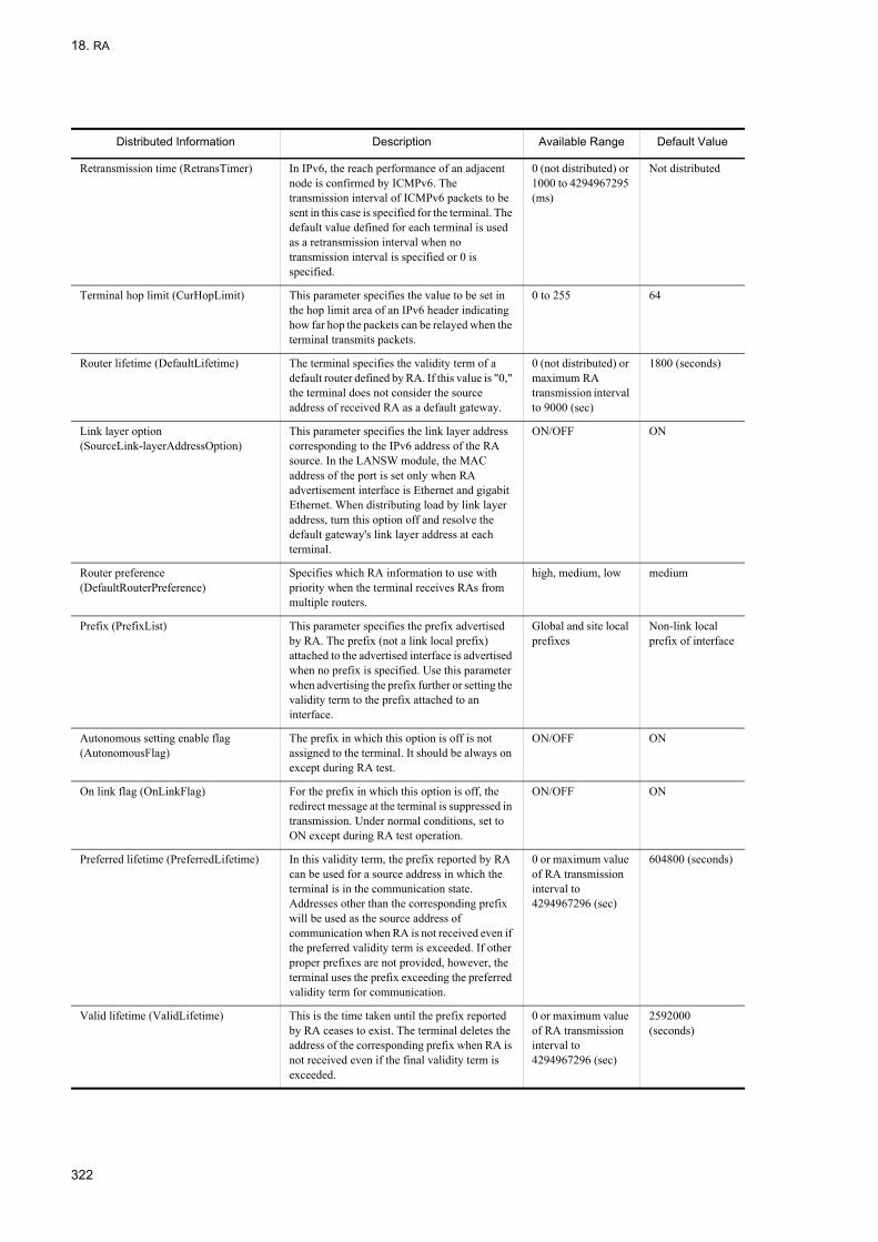
18. RA
Retransmission time (RetransTimer) In IPv6, the reach performance of an adjacent node is confirmed by ICMPv6. The transmission interval of ICMPv6 packets to be sent in this case is specified for the terminal. The default value defined for each terminal is used as a retransmission interval when no transmission interval is specified or 0 is specified.
0 (not distributed) or 1000 to 4294967295 (ms)
Not distributed
Terminal hop limit (CurHopLimit) This parameter specifies the value to be set in the hop limit area of an IPv6 header indicating how far hop the packets can be relayed when the terminal transmits packets.
0 to 255 64
Router lifetime (DefaultLifetime) The terminal specifies the validity term of a default router defined by RA. If this value is "0," the terminal does not consider the source address of received RA as a default gateway.
0 (not distributed) or maximum RA transmission interval to 9000 (sec)
1800 (seconds)
Link layer option (SourceLink-layerAddressOption)
This parameter specifies the link layer address corresponding to the IPv6 address of the RA source. In the LANSW module, the MAC address of the port is set only when RA advertisement interface is Ethernet and gigabit Ethernet. When distributing load by link layer address, turn this option off and resolve the default gateway's link layer address at each terminal.
ON/OFF ON
Router preference (DefaultRouterPreference)
Specifies which RA information to use with priority when the terminal receives RAs from multiple routers.
high, medium, low medium
Prefix (PrefixList) This parameter specifies the prefix advertised by RA. The prefix (not a link local prefix) attached to the advertised interface is advertised when no prefix is specified. Use this parameter when advertising the prefix further or setting the validity term to the prefix attached to an interface.
Global and site local prefixes
Non-link local prefix of interface
Autonomous setting enable flag (AutonomousFlag)
The prefix in which this option is off is not assigned to the terminal. It should be always on except during RA test.
ON/OFF ON
On link flag (OnLinkFlag) For the prefix in which this option is off, the redirect message at the terminal is suppressed in transmission. Under normal conditions, set to ON except during RA test operation.
ON/OFF ON
Preferred lifetime (PreferredLifetime) In this validity term, the prefix reported by RA can be used for a source address in which the terminal is in the communication state. Addresses other than the corresponding prefix will be used as the source address of communication when RA is not received even if the preferred validity term is exceeded. If other proper prefixes are not provided, however, the terminal uses the prefix exceeding the preferred validity term for communication.
0 or maximum value of RA transmission interval to 4294967296 (sec)
604800 (seconds)
Valid lifetime (ValidLifetime) This is the time taken until the prefix reported by RA ceases to exist. The terminal deletes the address of the corresponding prefix when RA is not received even if the final validity term is exceeded.
0 or maximum value of RA transmission interval to 4294967296 (sec)
2592000 (seconds)
Distributed Information Description Available Range Default Value
322

18. RA
18.1.3 Handling When Prefix Information Is ChangedIn a configuration where a prefix is distributed to a terminal via RA, when the value of the prefix is changed, a sudden address change may disable communication. To prevent it, the standard setting retains the old prefix for 604800 seconds (7 days). To delete the old prefix, therefore, advertise a new prefix simultaneously with the prefix to be changed and change the validity term gradually. The figure below shows an example of use in RA.
Figure 18-3: Example of Using RA
1. Set RA from the interface Ia of Ethernet for advertising it to each network.• Prefix of Ia = 3ffe:501:811:ff01::/64
2. Change the prefix of Ia from 3ffe:501:811:ff01::/64 to 3ffe:501:811:ff22::/64 in the procedure below.• Shorten the advertisement interval of prefix 3ffe:501:811:ff22::/64 newly advertised in Ia and initiate the
advertisement.• Shorten the preferred validity term and final validity term of prefix 3ffe:501:811:ff01::/64, to be cancelled in Ia,
and perform the advertisement.• Return the advertisement interval of 3ffe:501:811:ff22::/64 in Ia to the default value.• Stop the advertisement of prefix 3ffe:501:811:ff01::/64 for which advertisement is completed.
323

18. RA
18.2 Configuration
When the configuration command ipv6 address or ipv6 enable is executed, RA is sent automatically on interface where IPv6 is enabled.
Suppression of RA transmission and modification of various RA attributes should be performed independently for each interface.
18.2.1 List of Configuration CommandsThe following table provides a list of RA configuration commands.
Table 18-2: List of Configuration Commands
18.2.2 Setting RA Transmission SuppressionSuppress transmission of RA to interface.
[Point of setting]The ipv6 nd suppress-ra command is used to suppress transmission of RA.
[Setup using commands]
1. (config)# interface vlan 10
(config-if)# ipv6 nd suppress-ra
Suppresses transmission of RA on interface vlan 10.
2. (config-if)# ipv6 address 2001:db8:1:1::1/64
Assigns IPv6 address 2001:db8:1:1::1/64 to interface vlan 10.
Command Description
ipv6 hop-limit Specifies the initial value of the hop limit used when the terminal receiving RA performs transmission.
ipv6 nd link-mtu Specifies the MTU value for the link-mtu information transmitted by RA.
ipv6 nd managed-config-flag Apart from automatic address setting by RA, sets flag to enable terminal to automatically set address by method other than RA, such as DHCPv6.
ipv6 nd no-advertise-link-address Specifies not to include the link layer address corresponding to router IP address in RA.
ipv6 nd ns-interval Specifies the delivery interval of the control packets sent by the terminal receiving RA to confirm accessibility of the counterpart.
ipv6 nd other-config-flag Sets flag enable the terminal to automatically obtain information other than IPv6 address by method other than RA.
ipv6 nd prefix Specifies IPv6 prefix information sent to RA or prefix related information.
ipv6 nd ra-interval Specifies the minimum and maximum interval for sending RA.
ipv6 nd ra-lifetime Specifies the lifetime of the default route of a terminal set by RA.
ipv6 nd reachable-time Specifies the lifetime of information on reachability of neighboring nodes confirmed at transmission by terminal receiving RA.
ipv6 nd router-preference Specifies the type of router advertisement information that the terminal receiving multiple RA uses in preference.
ipv6 nd suppress-ra Suppresses RA transmission.
324
18. RA
18.2.3 Setting Information to Be DistributedSet information to be distributed by RA.
[Point of setting]Set the information distributed by RA in interface mode. Examples of setting other information configuration flag (OtherConfigFlag) with the ipv6 nd other-config-flag and router preference (DefaultRouterPreference) with the ipv6 nd router-preference command are shown.
[Setup using commands]
1. (config)# interface vlan 10
(config-if)# ipv6 nd other-config-flag
Sets other information configuration flag (OtherConfigFlag) in RA sent from interface vlan 10. The terminal obtains information other than address by method other than RA, such as DHCPv6, when it receives RA.
2. (config-if)# ipv6 nd router-preference high
Sets router preference (DefaultRouterPreference) of RA sent from interface vlan 10 to high.
18.2.4 Adjusting RA Transmission IntervalSet RA transmission interval.
[Point of setting]Use ipv6 nd ra-interval command to set the RA transmission interval.
[Setup using commands]
1. (config)# interface vlan 10
(config-if)# ipv6 nd ra-interval 600 1200
Sets to send RA at random interval between 10 and 20 minutes.
325

18. RA
18.3 Operation
18.3.1 List of Operation CommandsThe following table provides a list of RA operation commands.
Table 18-3: List of Operation Commands
18.3.2 Checking Summary InformationDisplay a list of interfaces sending RA.
Figure 18-4: List of Interfaces Sending RA
> show ipv6 routers globalDate 2005/07/14 12:00:00 UTC#Index Name Prefix#2 VLAN0010 2001:db8:1:1::/64#3 VLAN0020 2001:db8:1:2::/64#4 VLAN0030 2001:db8:1:3::/64
18.3.3 Checking Detail InformationDisplay detailed information of interfaces sending RA.
Figure 18-5: Detailed Information of Interfaces Sending RA
> show ipv6 routers interface vlan 10Date 2005/07/14 12:00:00 UTCIndex: 3, Name: VLAN0010Statistics:RSin(wait): 5(0), RAout: 10, RAin(invalid): 0(0)Intervals:Advertise: 600-1200s (next=219s later), RA Lifetime: 1800sReachable Time: ---, NS Interval: ---Managed Config Flag: off, Other Config Flag: on, Hop Limit: 64No Advertised Link Address: off, Link MTU: 1500 Prefix ValidLife[s] PrefLife[s] OnLink Autoconfig2001:db8:1:1::/64 2592000 604800 on on
Command Description
show ipv6 routers Displays the RA information.
show ipv6 interface Displays the IPv6 interface state.
show netstat (netstat) (IPv6) Displays the state and statistics of a network.
326

19. IPv6 DHCP Server Function
19 IPv6 DHCP Server FunctionThe IPv6 DHCP server function dynamically assigns the information such as a prefix and DNS server address to the IPv6 DHCP client. The assigning of prefix to IPv6 DHCP client by IPv6 DHCP server is referred to as prefix delegation.This chapter describes the IPv6 DHCP server function and configuration.
19.1 IPv6 DHCP Server Function Overview
19.2 Configuration
19.3 Operation
327

19. IPv6 DHCP Server Function
19.1 IPv6 DHCP Server Function Overview
The IPv6 DHCP server function dynamically assigns the information such as a prefix and DNS server address to the IPv6 DHCP client.
19.1.1 Support SpecificationsThe support specifications of an IPv6 DHCP server function in the LANSW module are shown in the table below. The IPv6 DHCP server and IPv6 DHCP client are directly connected in the same network.
Table 19-1: Support Specifications of IPv6 DHCP Server Function
19.1.2 Supported DHCP OptionsThe IPv6 DHCP options that are supported in the LANSW module are shown in the table below.
Table 19-2: IPv6 DHCP Options Supported by the LANSW module
Item Specification
Connection configuration IPv6 DHCP client directly stored
Via IPv6 DHCP relay
IPv4/IPv6 dual stack (IPv6 support) Supported
Option Code
Option Name Description Value Setting Method
1 Client Identifier The Client Identifier option is used to transfer DUID* that identifies the client between the client and server.
Y/N
2 Server Identifier The Server Identifier option is used to transfer DUID that identifies the server between the client and server.
Y
3 Identity Association option
The identity Association (IA) option is used to transfer identity association, an IA-related parameter, and an IA-related address.
-
4 Identity Association for Temporary Addresses option
Identity Association for Temporary Addresses (IA_TA) option is used to transfer IA, an IA-related parameter, and an IA-related address. As prescribed in RFC3041, all addresses in this option are used as a temporary address by the client.
-
5 IA Address option The IA Address option is used to specify an IA-related IPv6 address. It must be encapsulated in the Options field of an Identity Association option. The Options field encapsulates options peculiar to this address.
-
6 Option Request The Option Request option is used to identify the option list in a message between the client and server.
Y
7 Preference The Preference option is transferred to the client by the server because it influences the selection of the server by the client.
Y
8 Elapsed Time option The Elapsed Time option is used to indicate to which extent the client has completed the exchange of an IPv6 DHCP message. The time elapsed is measured from the time in which the client sent the first message during message exchange. During message exchange, the elapsed-time field of the first message is set to "0". For example, when the primary server does not reply in reasonable time, this option permits the secondary IPv6 DHCP server to comply with the request.
-
9 Relay Message option The Relay Message option transfers the IPv6 DHCP message in a Relay-forward or Relay-reply message.
Y
11 Authentication option The authentication option transfers authentication information to identify an IPv6 DHCP message and authenticate its contents.
-
328

19. IPv6 DHCP Server Function
(Legend)A: Set with configuration Y: Set automaticallyY/N: Use value set by client -: Unsupported (ignore)
* DHCP Unique Identifier
19.1.3 Route Information of Distributed PrefixThe two methods below are provided as the route setting to the distributed prefix when the LANSW module is used as the gateway of the client.
12 Server unicast option The server sends this option to the client so as to notify the client that it is not permitted for the client to unicast a message to the server.
-
13 Status Code The Status Code option returns the value of the status display related to the IPv6 DHCP message or option in which it appears.
Y
14 Rapid Commit The Rapid Commit option is used to sign the replacement of two messages for address assignment.
Y
15 User Class option The User Class option is used by the client to identify the type or category of the user or application that it displays.
-
16 Vendor Class Option The Vendor Class option is used by the client to identify the vendor that manufactures the hardware by which the client operates. The information contained in the data area of this option is contained in one or more indistinct fields that identify the detail of hardware configuration.
-
17 Vendor-specific Information option
The vendor-specific Information option is used by the client and server to exchange vendor-specific information.
-
18 Interface-Id Option A relay agent can send an Interface-id option to identify the interface in which a client message was received. When a relay agent receives a Relay-reply message that has an Interface-ld option, it transfers the message to the client through the interface identified using the option.
-
19 Reconfigure Message option
The server contains a Reconfigure Message option in Reconfigure Message to indicate it to the client whether the client complies with a Renew message or Information-request message.
-
20 Reconfigure Nonce option
The server stores a nonce value for each client when it uses reconfigure nonce to provide security for Reconfigure Message.The server first notifies the client of a nonce value and then contains the nonce value in every Reconfigure Message sent to the client.
-
21 SIP Servers Domain Name List
Outbound proxy server's domain name of SIP that the client uses. A
22 SIP Servers IPv6 Address List
This option specifies the list of an IPv6 address indicating the outbound proxy server of SIP that can be used for the client.
A
23 DNS Recursive Name Server
The Domain Search List option is specified when the server transfers the address of the DNS server to the client in a list format.
A
24 Domain Search List When the client receives this option, it searches for a host name from the domain list assigned to the host name in the case where it solves a host name by DNS. Use this option only to solve a host name.
A
25 Identify Association for Prefix Delegation Option
This option is used to transfer the data related to Prefix Delegation identity. A
26 IA_PD Prefix Option The IPv6 address prefix specifies the association with IA_ID. A
31 Network Time Protocol (NTP) Servers
The Network Time Protocol Servers option is used when the server notifies the client of the address list of the NTP server.
A
Option Code
Option Name Description Value Setting Method
329

19. IPv6 DHCP Server Function
• When the client has no advertisement function of route informationThe route to the distribution destination is automatically added to the LANSW module by validating an automatic route setting function for the distributed prefix of IPv6 DHCP server configuration in the LANSW module.Moreover, the preference value of the route set at that time is fixed to 250.
• When the client has the advertisement function of route informationIn this case, the automatic route setting function for the distributed prefix of IPv6 DHCP server configuration in the LANSW module should be invalidated because route information is exchanged between the LANSW module and the client and the route is automatically generated.
19.1.4 Notes on Using IPv6 DHCP Server FunctionNotes on using the IPv6 DHCP server function are described below.
(1) DUID (DHCP Unique Identifier)
The LANSW module generates DUID prescribed to be used to distinguish a system using IPv6 DHCP when an IPv6 DHCP server function is first installed. The generated DUID is saved statically in system memory. The value of DUID can be checked by Server DUID displayed with the show ipv6 dhcp server statistics command. The DUID will be different if the System is replaced or is restarted. Reset with the set ipv6-dhcp server duid command if you need to use the previous DUID.
(2) Operation when restarting the LANSW module
The LANSW module has limitations exposed in the states below. The retention characteristics of information in each state are shown in the table below.
Table 19-3: Retention Characteristics of Information in Each State
(Legend)Y: Guaranteed.Y/N: Guaranteed. Some information distributed immediately before may not be reflected.N: Not guaranteed (each status information is initialized).
(3) Note on using the automatic route setting function for distribution prefix
The LANSW module can automatically set the route information without using the route advertisement function in certain cases (for example, when a client does not have the route advertisement function). However, when multipath is used or a route is dynamically changed, enable the route advertisement function instead.
Also when any other system exists between a client and the LANSW module, the route advertisement function must be used because the route information is not advertised to that system.
(4) Notes regarding the use of the IPv6 DHCP server and IPv6 PIM through the same interface
When using the IPv6 DHCP server in an interface where IPv6 PIM is enabled, the DHCP control packet from the IPv6 DHCP relay must be sent not to the all-server multicast but to the global unicast address for this device
Retention Information Concerning Prefix Server Function Restart The LANSW module Restart
restart ipv6-dhcpserver Command Execution
Server Failure
Route information to client Y Y/N N
Distribution information to client Y Y/N N
330

19. IPv6 DHCP Server Function
19.2 Configuration
19.2.1 List of Configuration CommandsThe following table provides a list of IPv6 DHCP server configuration commands.
Table 19-4: List of Configuration Commands
19.2.2 Flow of IPv6 DHCP Server Configuration
(1) Setting to distribute fixed prefix to client
1. Enable the use of IPv6 with the swrt_table_resource command.2. Set the VLAN interface with the interface command.3. Set the IPv6 address with the ipv6 address command.4. Set to automatically generate IPv6 address with the ipv6 enable command.5. Set fixed prefix for each client.6. Distribute prefix to client.7. Set to automatically generate the route of the prefix destination client.
(2) Setting to dynamically distribute prefix to client
1. Enable the use of IPv6 with the swrt_table_resource command.2. Set the VLAN interface with the interface command.
Command Description
dns-server Sets IPv6 DHCP server DNS server address. DNS server address information can be distributed according to request from IPv6 DHCP client.
domain-name Sets the IPv6 DHCP server domain name information. Domain name information can be distributed according to request from IPv6 DHCP client.
ipv6 dhcp pool Sets the IPv6 DHCP address pool information. Transition can be made to configure DHCP mode as described in "19.2.3 Setting Fixed Prefix for Each Client" and fixed prefix can be set.
ipv6 dhcp server Configures to distribute prefix. The server priority is set in "19.2.5 Setting Priority to Distribute Prefix to Client" in order to distribute the prefix priority.
ipv6 dhcp static-route-setting Automatically adds the route information for the clients that have received prefixes from the IPv6 DHCP server, to the routing table of the LANSW module. Used as described in the example in "19.2.6 Setting to Automatically Generate Route to Client to Which Prefix Is Distributed".
ipv6 local pool Sets prefix allocated dynamically. Used as described in the example in "19.2.4 Setting Range to Provide Dynamic Prefix".
prefix-delegation Sets the fixed IPv6 prefix and IAID, lifetime used within the specified pool. Used as described in the example in "19.2.3 Setting Fixed Prefix for Each Client".
prefix-delegation pool Sets IAID and lifetime for the IPv6 prefix range specified with the local pool setting. Used as described in the example in "19.2.4 Setting Range to Provide Dynamic Prefix".
service ipv6 dhcp Sets whether the IPv6 DHCP server is used or not.
sip-domain-name Sets the IPv6 DHCP server SIP domain name information. SIP domain name information can be distributed according to request from IPv6 DHCP client.
sip-server Sets the SIP server IPv6 address information of IPv6 DHCP server. SIP server IPv6 address information can be distributed according to request from IPv6 DHCP client.
sntp-server Sets IPv6 DHCP server SNTP server address. SNTP server address information can be distributed according to request from IPv6 DHCP client.
331
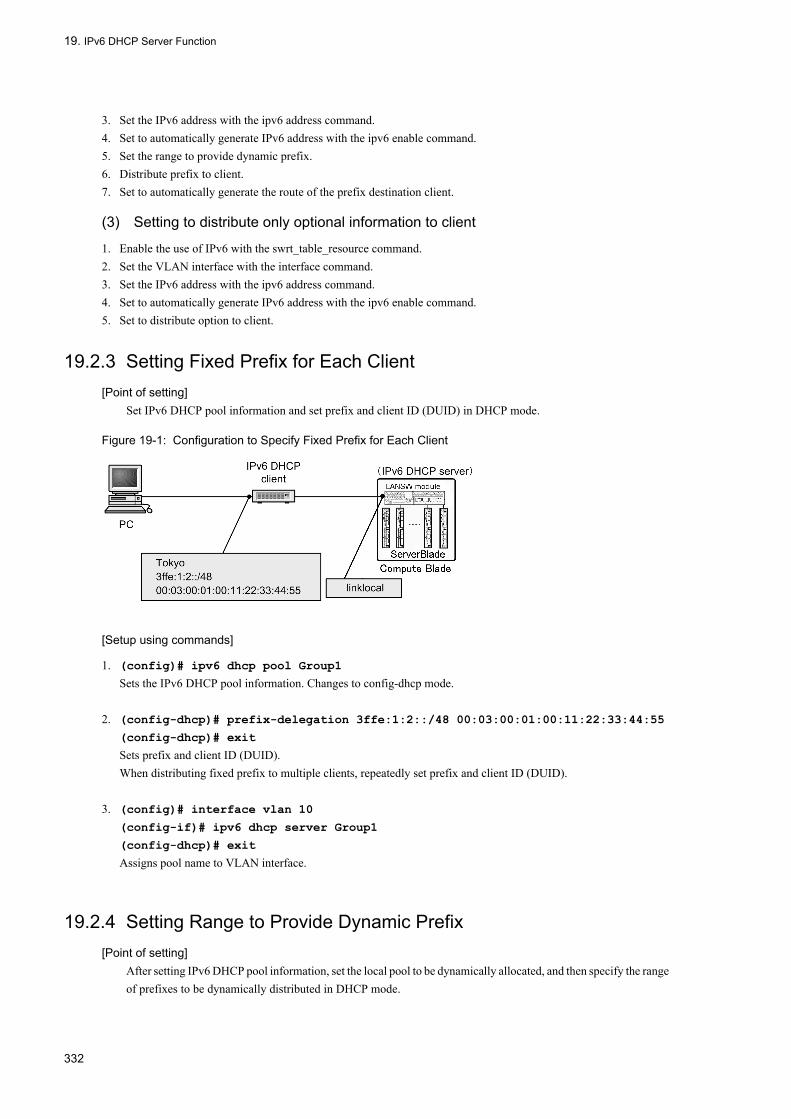
19. IPv6 DHCP Server Function
3. Set the IPv6 address with the ipv6 address command.4. Set to automatically generate IPv6 address with the ipv6 enable command.5. Set the range to provide dynamic prefix.6. Distribute prefix to client.7. Set to automatically generate the route of the prefix destination client.
(3) Setting to distribute only optional information to client
1. Enable the use of IPv6 with the swrt_table_resource command.2. Set the VLAN interface with the interface command.3. Set the IPv6 address with the ipv6 address command.4. Set to automatically generate IPv6 address with the ipv6 enable command.5. Set to distribute option to client.
19.2.3 Setting Fixed Prefix for Each Client[Point of setting]
Set IPv6 DHCP pool information and set prefix and client ID (DUID) in DHCP mode.
Figure 19-1: Configuration to Specify Fixed Prefix for Each Client
[Setup using commands]
1. (config)# ipv6 dhcp pool Group1
Sets the IPv6 DHCP pool information. Changes to config-dhcp mode.
2. (config-dhcp)# prefix-delegation 3ffe:1:2::/48 00:03:00:01:00:11:22:33:44:55
(config-dhcp)# exit
Sets prefix and client ID (DUID).When distributing fixed prefix to multiple clients, repeatedly set prefix and client ID (DUID).
3. (config)# interface vlan 10
(config-if)# ipv6 dhcp server Group1
(config-dhcp)# exit
Assigns pool name to VLAN interface.
19.2.4 Setting Range to Provide Dynamic Prefix[Point of setting]
After setting IPv6 DHCP pool information, set the local pool to be dynamically allocated, and then specify the range of prefixes to be dynamically distributed in DHCP mode.
332

19. IPv6 DHCP Server Function
Figure 19-2: Configuration to Dynamically Assign Prefix
[Setup using commands]
1. (config)#ipv6 local pool Group1Local 3ffe:ffff:1100::/44 48
Sets prefix dynamically distributed to client.
2. (config)# ipv6 dhcp pool Group1
Sets the IPv6 DHCP pool information.
3. (config-dhcp)# prefix-delegation pool Group1Local
(config-dhcp)# exit
Sets local pool name set with local pool setting information.
4. (config)# interface vlan 10
(config-if)# ipv6 dhcp server Group1
(config-dhcp)# exit
Assigns pool name to VLAN interface.
19.2.5 Setting Priority to Distribute Prefix to Client[Point of setting]
Set server priority in order to distribute prefix.
[Setup using commands]
1. (config)#ipv6 local pool Group1Local 3ffe:ffff:1100::/44 48
(config)# ipv6 dhcp pool Group1
(config-dhcp)# prefix-delegation pool Group1Local
(config-dhcp)# exit
Sets IPv6 DHCP pool information in advance. The prefix setting is a dynamic setting example.
2. (config)# interface vlan 10
(config-if)# ipv6 dhcp server Group1 preference 255
This is an example to set server priority to 255 in order to distribute prefix.
19.2.6 Setting to Automatically Generate Route to Client to Which Prefix Is Distributed
[Point of setting]Set to automatically generate route to client to which prefix is distributed.
333

19. IPv6 DHCP Server Function
[Setup using commands]
1. (config)#ipv6 local pool Group1Local 3ffe:ffff:1100::/44 48
(config)# ipv6 dhcp pool Group1
(config-dhcp)# prefix-delegation pool Group1Local
(config-dhcp)# exit
Sets IPv6 DHCP pool information in advance. The prefix setting is a dynamic setting example.
2. (config)# interface vlan 10
(config-if)# ipv6 dhcp server Group1
(config-if)# exit
Assigns pool name to VLAN interface.
3. (config)# ipv6 dhcp static-route-setting
Enables automatic route setting function to prefix distribution destination from outside of the LANSW module. However, no route will be set up, until the distribution of prefixes is complete.
19.2.7 Setting to Distribute Only Optional Information to Client[Point of setting]
Set to distribute only optional information such as DNS server option, to client that does not need prefix.
Figure 19-3: Configuration to Distribute Optional Information to Client
[Setup using commands]
1. (config)#ipv6 local pool Group1Local 3ffe:ffff:1100::/44 48
Sets prefix dynamically distributed to client.
2. (config)# ipv6 dhcp pool Group1
Sets the IPv6 DHCP pool information.Changes to config-dhcp mode.
3. (config-dhcp)# prefix-delegation pool Group1Local
Sets local pool name set with local pool setting information.
4. (config-dhcp)# dns-server 3ffe::1
(config-dhcp)# exit
Sets DNS server option.
5. (config)# interface vlan 10
(config-if)# ipv6 dhcp server Group1
334

19. IPv6 DHCP Server Function
(config-if)# exit
Assigns pool name to VLAN interface.
335
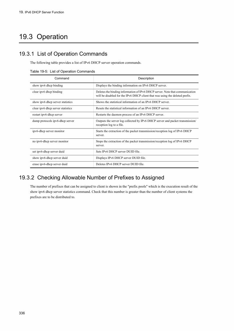
19. IPv6 DHCP Server Function
19.3 Operation
19.3.1 List of Operation CommandsThe following table provides a list of IPv6 DHCP server operation commands.
Table 19-5: List of Operation Commands
19.3.2 Checking Allowable Number of Prefixes to AssignedThe number of prefixes that can be assigned to client is shown in the "prefix pools" which is the execution result of the show ipv6 dhcp server statistics command. Check that this number is greater than the number of client systems the prefixes are to be distributed to.
Command Description
show ipv6 dhcp binding Displays the binding information on IPv6 DHCP server.
clear ipv6 dhcp binding Deletes the binding information of IPv6 DHCP server. Note that communication will be disabled for the IPv6 DHCP client that was using the deleted prefix.
show ipv6 dhcp server statistics Shows the statistical information of an IPv6 DHCP server.
clear ipv6 dhcp server statistics Resets the statistical information of an IPv6 DHCP server.
restart ipv6-dhcp server Restarts the daemon process of an IPv6 DHCP server.
dump protocols ipv6-dhcp server Outputs the server log collected by IPv6 DHCP server and packet transmission/reception log to a file.
ipv6-dhcp server monitor Starts the extraction of the packet transmission/reception log of IPv6 DHCP server.
no ipv6-dhcp server monitor Stops the extraction of the packet transmission/reception log of IPv6 DHCP server.
set ipv6-dhcp server duid Sets IPv6 DHCP server DUID file.
show ipv6-dhcp server duid Displays IPv6 DHCP server DUID file.
erase ipv6-dhcp server duid Deletes IPv6 DHCP server DUID file.
336

19. IPv6 DHCP Server Function
Figure 19-4: Execution Result of show ipv6 dhcp server statistics Command
> show ipv6 dhcp server statistics < DHCP Server use statistics > prefix pools :20 automatic prefixes :50 manual prefixes :4 expired prefixes :3 over pools requests :0 discard packets :0 < Receive Packets > SOLICIT :54 REQUEST :54 RENEW :54 REBIND :0 INFORMATION-REQUEST :0 CONFIRM :0 RELEASE :0 DECLINE :0 RELAY-FORW :0 < Send Packets > ADVERTISE :54 REPLY :108 RELAY-REPL :0 < Server DUID > 00:01:00:01:3e:00:2e:22:11:22:33:44:55:01>
19.3.3 Checking Distributed PrefixesCheck the actually distributed prefix by executing the show ipv6 dhcp binding command. The prefix addresses for which the lease is not expired are displayed.
Figure 19-5: Execution Result of show ipv6 dhcp binding Command
> show ipv6 dhcp bindingTotal: 2 prefixes<Prefix> <Lease expiration> <Type>3ffe:1:2::/48 05/09/01 11:15:00 Manual3ffe:ffff:1101::/48 05/09/01 11:29:00 Automatic>
337

19. IPv6 DHCP Server Function
338
20. General Description of IPv6 Routing Protocol
Part 4 IPv6 Routing Protocol
20General Description of IPv6 Routing ProtocolThis chapter provides a general description of the IPv6 routing protocol.
20.1 IPv6 Routing Overview
20.2 General Operation of IPv6 Routing
20.3 Network Design Concept
20.4 Load Balancing Overview
20.5 Configuration of Load Balancing
20.6 Operation of Load Balancing
20.7 Route Aggregation Overview
20.8 Configuration of Route Aggregation
20.9 Operation of Route Aggregation
20.10 Route Deletion Reserve Function
339

20. General Description of IPv6 Routing Protocol
20.1 IPv6 Routing Overview
20.1.1 Outline of RoutingThe routing protocol exchanges the route information with the neighboring router. The route information learned by each routing protocol is held in the routing table. The optimum route information is registered in the forwarding table as destination. The packet is relayed according to the forwarding table.
Figure 20-1: Outline of Routing
20.1.2 Static Routing and Dynamic RoutingA routing table must be created to relay packets. The methods used to create the routing table of the LANSW module are classified into static routing and dynamic routing.
• Static routingIn this method, the user sets route information using configuration.
• Dynamic routingIn this method, the user replaces route information for other routers in a network and determines the relay route. The LANSW module supports RIPng, OSPFv3, and BGP4+.
20.1.3 Route InformationThe route information (type of address used for routing) used by the LANSW module is described below. The LANSW module handles a site local address as a global address.
340

20. General Description of IPv6 Routing Protocol
Table 20-1: Route Information
(Legend) -: Nothing is particular
20.1.4 Application Scope by Routing ProtocolThe table below shows the application of routing protocols by route information, and additional features supported for these protocols.
Table 20-2: Application Scope by Routing Protocol
(Legend) Y: Supported N: Not supported -: N/A
20.1.5 Simultaneous Operation of Routing ProtocolEach static and dynamic routing protocol can operate simultaneously.
(1) Selecting priority of learned route
When multiple routing protocols run concurrently, each selects the best route from the route information to the destination address according to its own route selection procedure. As a result, the multiple route information to one destination address exists in the LANSW module. In this case, the distance value of each route's information are compared and the route information that has high priority becomes valid.
With the LANSW module, you can configure the default distance (priority) of the route information generated for each static route and dynamic routing protocol (i.e., RIPng). Smaller distance value results in higher priority. The following table shows the default distance value for each protocol.
Route Information Type Description
Normal route Default route Route to all networks (destination prefix: ::/0).
Global network route with 1 to 64 bit prefix Route aggregating global route to specific network and global routes to multiple networks.
Global host route Route to specific host (global route with 128 bit prefix)
Routes excluded from routing
Link local path (Prefix: fe80::% interface name/64)
Global network route with 65 to 127 bit prefix -
Multicast Address (Prefix: ff00::/8)
IPv4 reserved address (Prefix: ::/8)
Route information Static Dynamic
RIPng OSPFv3 BGP4+
Route information
Default route Y Y Y Y
Global network route Y Y Y Y
Global host route Y Y Y Y
Multipath Y N Y Y
Route selection - Metric (number of routers in route)
Cost (number of routers and line speed)
AS path attribute
Routing loop suppression - Split horizon Y Y
Authentication function - N N Y
341
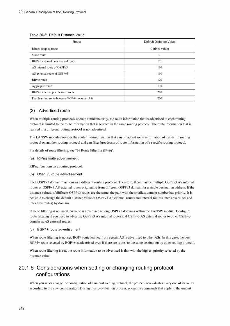
20. General Description of IPv6 Routing Protocol
Table 20-3: Default Distance Value
(2) Advertised route
When multiple routing protocols operate simultaneously, the route information that is advertised to each routing protocol is limited to the route information that is learned in the same routing protocol. The route information that is learned in a different routing protocol is not advertised.
The LANSW module provides the route filtering function that can broadcast route information of a specific routing protocol on another routing protocol and can filter broadcasts of route information of a specific routing protocol.
For details of route filtering, see "26 Route Filtering (IPv6)".
(a) RIPng route advertisement
RIPng functions as a routing protocol.
(b) OSPFv3 route advertisement
Each OSPFv3 domain functions as a different routing protocol. Therefore, there may be multiple OSPFv3 AS internal routes or OSPFv3 AS external routes originating from different OSPFv3 domain for a single destination address. If the distance values, of different OSPFv3 routes are the same, the path with the smallest domain number has priority. It is possible to change the default distance value of OSPFv3 AS external routes and internal routes (inter-area routes and intra area routes) by domain.
If route filtering is not used, no route is advertised among OSPFv3 domains within the LANSW module. Configure route filtering if you need to advertise OSPFv3 AS internal routes and OSPFv3 AS external routes to other OSPFv3 domain as AS external routes.
(c) BGP4+ route advertisement
When route filtering is not set, BGP4 route learned from certain AS is advertised to other ASs. In this case, the best BGP4+ route selected by BGP4+ is advertised even if there are routes to the same destination by other routing protocol.
When route filtering is set, the route information to be advertised is that with the highest priority selected by the distance value.
20.1.6 Considerations when setting or changing routing protocol configurations
When you set or change the configuration of a unicast routing protocol, the protocol re-evaluates every one of its routes according to the new configuration. During this re-evaluation process, operation commands that apply to the unicast
Route Default Distance Value
Direct-coupled route 0 (fixed value)
Static route 2
BGP4+ external peer learned route 20
AS internal route of OSPFv3 110
AS external route of OSPFv3 110
RIPng route 120
Aggregate route 130
BGP4+ internal peer learned route 200
Peer learning route between BGP4+ member ASs 200
342

20. General Description of IPv6 Routing Protocol
routing protocol might take a long time to execute, and MIB information might take a long time to gather via SNMP.
343

20. General Description of IPv6 Routing Protocol
20.2 General Operation of IPv6 Routing
20.2.1 List of Operation CommandsThe following table provides a list of IPv6 routing protocol common operation commands.
Table 20-4: List of Operation Commands
20.2.2 Checking Route to Destination AddressIf IPv6 unicast routing information is set on the LANSW module, execute the command "show ipv6 route" and make sure that the route to the destination address exists.
Figure 20-2: Execution Result of show ipv6 route Command
> show ipv6 routeDate 2005/07/14 12:00:00 UTCTotal: 11 routesDestination Next Hop Interface Metric Protocol Age4000:110:1:1::/64 4000:110:1:1::1 VLAN0010 0/0 Connected 22m 53scafe:1001::/64 4000:110:1:1::200 ...1 VLAN0010 0/0 Static 41s : :>
Command Description
show system Displays the operation state.
ping ipv6 Sends test packet to the system at specified IPv6 address to determine whether communication is enabled.
show ip-dual interface (IPv6) Displays the IPv4 and IPv6 interface state.
show ipv6 interface Displays the IPv6 interface state.
show netstat (netstat) (IPv6) Displays the state and statistics of a network.
traceroute ipv6 Displays route to destination host traveled by IPv6 datagram.
show processes cpu unicast Displays the CPU usage of the unicast routing program.
debug protocols unicast Starts operation message display of the event log information that a unicast routing program outputs.
dump protocols unicast Outputs the trace information and control table information collected by a unicast routing program to a file.
erase protocol-dump unicast Deletes the trace information file and control table information file created by a unicast routing program.
no debug protocols unicast Stops operation message display of the event log information that the unicast routing program outputs.
restart unicast Restarts the unicast routing program.
show ipv6 interface ipv6-unicast Displays the IPv6 interface information of the LANSW module recognized by a unicast routing program.
debug ipv6 Displays packet exchanged by IPv6 routing protocol in real time.
clear ipv6 route Clears and re-enters IPv6 forwarding entry in hardware.
show ipv6 entry Displays detailed information on specific IPv6 unicast route.
show ipv6 route Displays the route information held in the routing table.
344

20. General Description of IPv6 Routing Protocol
1. Check whether the route to the destination address exists.
345

20. General Description of IPv6 Routing Protocol
20.3 Network Design Concept
This section describes the IPv6 network design concept.
20.3.1 Address DesignThe following IPv6 address assignment concept is helpful in avoiding the troubles and simplifying network design.
• Divide NLA or SLA according to the hierarchical network's topology structure.
20.3.2 Handling of Direct RouteThe LANSW module handles broadcast type line.
Broadcast type supports network prefix (prefix) and prefix length (prefixlen). The figure below shows the broadcast line connection.
Figure 20-3: Handling of Direct Route (Broadcast Type)
346

20. General Description of IPv6 Routing Protocol
20.4 Load Balancing Overview
20.4.1 Outline of Load BalancingThis load balancing is a function to disperse the increasing traffic load in routing control of the IP layer by means of multipath connection. For detail of load balancing, see "6.4.1 Outline of Load Balancing".
20.4.2 Load Balancing SpecificationsTable below shows the multipath specification implemented by the LANSW module and the load balancing specification.
Table 20-5: IPv6 Multipath Specifications
(Legend) -: Not applicable
Table 20-6: IPv6 Load Balancing Specifications
(Legend) -: Not applicable
Item Specification Remarks
Number of multipaths to a single destination network
2 to 16 -
Maximum number of multipaths which can be specified in configuration
1 to 16 (when 1, no multipath is generated) Specified for each routing protocol.
Maximum number of multipath routes 1 to 128 Regardless of number of multipath, up to 128 routes (both IPv4 and IPv6 routes included) can be specified.
Routing protocol that can generate multipath.
• Static (IPv6)• OSPFv3• BGP4+
-
Number of multipaths in default configuration
• Static (IPv6): 6• OSPFv3:4• BGP4+: 1 (no multipath generated)
-
Connection mode Can be used regardless of line type and interface type. Coexistence is also permitted.
-
Item Specification Remarks
Determination of multipath Calculates the value to divide into 16 paths from destination IPv6 address and source IPv6 address (hash value), and divide them into decided output paths.For packets whose destination IPv6 address and source IPv6 address are the same, selects the same output paths. Thus guaranteeing the order of transmission.
-
Multipath information in routing table Hash allocation ratio for each output interface set in routing table is nearly uniform.
See 1 in "20.4.4 Notes on Load Balancing".
Weighting of path Not available.
Processing of packets exceeding bandwidth
Not reallocated to other path. If packets exceed bandwidths in continuation, they are retained in the system. If it is impossible, packets are discarded.
347

20. General Description of IPv6 Routing Protocol
20.4.3 Determination of Outgoing InterfaceUpon deciding the entry applicable to the destination IPv6 in retrieving the routing table, the output interface is decided. The output interface is decided by generating the hash value from the source IPv6 address and the destination IPv6 address of the received IPv6 packet, by which one of the multipath candidates is selected. The following figure illustrates how the outgoing interface is determined.
Figure 20-4: Determination of Outgoing Interface
20.4.4 Notes on Load Balancing1. By uniformly selecting one path out of the 16 paths by using the hash value, the packet distribution ratio of each
packet to the destination network will not necessarily be uniform.2. Since the weighting to each path is not available, distribution is not proportional to the speed if the line speed is
different. However, priority can be given to faster line by using multihome connection although redundant configuration is necessary in case of failure.
3. If an attempt is made to send packets continuously in excess of the output bandwidth of the selected path, packet abolition will occur. Such a packet is not re-allocated to the other path.
4. In the case of identifying the selected path used in the load balancing by traceroute (IPv6), the following points require attention:• The system receiving a traceroute (IPv6) command returns reply with the IPv6 address of the interface that
received the traceroute as the source IPv6 address, but it does not necessarily use that interface to return the reply.• In a case where the interface receiving a traceroute (IPv6) command is multihomed, it is not possible to determine
which subnet the neighboring system used for transmission. Therefore, the response is given by using one address out of the multihomes as the source IPv6 address.
5. Forwarding performance may be degraded significantly if traffic is concentrated at only certain forwarding route (gateway) when using load balancing. In such case, configure static NDP for all forwarding routes (gateway).
348

20. General Description of IPv6 Routing Protocol
20.5 Configuration of Load Balancing
20.5.1 List of Configuration Commands The following table lists the commands used to configure load balancing.
List of configuration commands
#1
See “12 BGP4 in the manual Configuration Commands, Vol. 2”.
#2
See “22 Static Routing (IPv6) in the manual Configuration Commands, Vol. 2”.
#3
See “24 OSPFv3 in the manual Configuration Commands, Vol. 2”.
20.5.2 Configuring the maximum number of multiple paths handled by the Switch
The maximum number of multiple paths used for each protocol in the Switch determines the maximum number of paths that the Switch handles and the maximum number of multipath routes that the Switch can accommodate.
The maximum number of multiple paths is determined at startup, and any changes made by configuration commands do not take effect until the switch is restarted. If you use a configuration command in a manner that affects the maximum number of multiple paths, a warning-level operation message appears prompting you to restart the switch. The new values for the maximum number of multiple paths and multipath routes will take effect after the Switch restarts.
[Point of setting]By default, the switch handles a maximum of 16 paths. Each path can contain 128 routes. To change the maximum number of multiple paths that the switch handles, you must restart the Switch after setting the maximum number of multiple paths in the configuration of a unicast routing protocol. For this reason, we recommend that you set the maximum number of multiple paths when you first deploy the switch.The configuration below uses an example of IPv6 static routing.
[Setup using commands]
1. (config)# ipv6 route static maximum-paths 2
In configuration mode, the command sets 2 as the maximum number of multiple paths for IPv6 static routes.
2. (config)# ipv6 route 2001:db8:ffff:2::/64 2001:db8:2:1::2 noresolve
(config)# ipv6 route 2001:db8:ffff:2::/64 2001:db8:2:2::2 noresolve
Command name Description
maximum-paths (BGP4+)#1 When multiple routing information entries of equal cost to a given destination exist, this command generates multiple paths using the specified value as the maximum number of paths.
ipv6 route static maximum-paths#2 Specifies the maximum number of paths (maximum number of next hops) that the routing protocol will generate for a static IPv6 route.
maximum-paths (OSPFv3)#3 When multiple paths (next hop) of equal cost exist for an OSPFv3-generated route, this command specifies the maximum number of paths in the route.
349

20. General Description of IPv6 Routing Protocol
In configuration mode, the commands establish a static IPv6 multipath route (2001:db8:ffff:2::/64).
3. (config)# save
(config)# exit
Saves the settings and switches from configuration mode to administrator mode.
4. # reload
Restarts the Switch.
20.5.3 Load Balancing Using Static RouteSee "21.2.4 Setting Multipath Route".
20.5.4 Load Balancing Using OSPFv3 See "23.2.6 Setting Multipath".
20.5.5 Load Balancing Using BGP4+ See "25.5.3 Configuring BGP4+ Multipath".
350

20. General Description of IPv6 Routing Protocol
20.6 Operation of Load Balancing
20.6.1 Checking the maximum number of multiple paths handled by the Switch
Use the show system command to check the maximum number of multiple paths handled by the Switch.
Figure 20-5: Checking the maximum number of multiple paths handled by the switch
>show system : : Device resources Current selected swrt_table_resource: l3switch-2 Current selected swrt_multicast_table: On Current selected unicast multipath number: 8 : :>
20.6.2 Checking Selected Path
(1) Checking route information
Execute the show ipv6 route command and check to see if the contents of setting the multipath route are correctly reflected.
Figure 20-6: Displaying Multipath Route Information
> show ipv6 routeDate 2005/07/14 12:00:00 UTCTotal: 11 routesDestination Next Hop Interface Metric Protocol Age4000:110:1:1::/64 4000:110:1:1::1 VLAN0010 0/0 Connected 22m 53s4000:110:1:1::1/128 ::1 localhost 0/0 Connected 22m 53s4000:120:1:1::/64 4000:120:1:1::1 VLAN0020 0/0 Connected 22m 53s4000:120:1:1::1/128 ::1 localhost 0/0 Connected 22m 53s4000:130:1:1::/64 4000:130:1:1::1 VLAN0030 0/0 Connected 22m 53s4000:130:1:1::1/128 ::1 localhost 0/0 Connected 22m 53s4000:210:1:1::/64 4000:110:1:1::200 VLAN0010 0/0 Static 6s 4000:120:1:1::200 VLAN0020 - - - 4000:130:1:1::200 VLAN0030 - - - : :>
(2) Checking whether communication with destination address is enabled
Execute the command "ping ipv6 <IPv6 Address > specific-route source <Source Address>" and check to see if the interface on the LANSW module used for load balancing can communicate with the remote system. For <Source Address> of the ping command, specify the local IPv6 address on the LANSW module of the interface to be used for load balancing.
351
20. General Description of IPv6 Routing Protocol
20.7 Route Aggregation Overview
20.7.1 Outline of Route AggregationRoute aggregation generates the shorter route information of a network mask that contains applicable route information from one or more sources. This is used to decrease the amount of route information on a network by generating a single route information containing applicable route information from multiple sources and distributing the aggregate route to adjacent routes. For example, when the route information of 2001:db8:1:ff01::/64 and 2001:db8:1:ff02::/64 are learned, the aggregated route information 2001:db8:1:ff00::/56 is generated.
Aggregation must be specified explicitly by configuration command ipv6 summary-address. Distance value can be specified for the aggregated route. When distance value is not specified, default value (130) is used. Aggregated route information is not generated when the aggregation source route information is not learned.
20.7.2 Transfer Method of Aggregated RouteThe aggregated route is a rejection route. If a packet does not have a priority route, it is discarded.
The reason why the aggregated route is a rejection route is to prevent a loop. If the aggregated route were advertised, a packet sent to the aggregation route would be transferred to the LANSW module. In such a case, if the LANSW module transfers a packet without an aggregation source route according to the second-best route such as a default route, a routing loop may occur between the destination system of the default route and the LANSW module. To prevent this situation, the aggregated route is designated as a rejection route.
However, the aggregated route with the noinstall parameter specified does not discard a packet. When the second-best route such as a default route is available, a packet is transferred according to that route. The noinstall parameter is used when it should be better to transfer a packet according to the next-best route rather than discarding on the aggregated route set for advertisement.
20.7.3 Aggregation of AS_PATH AttributeIf a BGP4+ route is contained in aggregation source route, add the path attribute of BGP4+ route to the aggregated route. If there are multiple BGP4+ route aggregation sources, aggregate the path attributes among aggregation source routes. Edit the aggregated route's AS_PATH attribute and COMMUNITIES attribute as follows.
(1) AS_PATH attribute
The section from starting of AS path within AS_SEQUENCE type of AS_PATH attribute, which is common among aggregation source routes, is set to AS_SEQUENCE type of AS_PATH attribute of the aggregated route. For AS paths in AS_SEQUENCE type other than the above and AS paths that are not AS_SEQUENCE type, set as the AS_SET type of AS_PATH attribute of the aggregated route only when as_set parameter is specified with the configuration command ipv6 summary-address.
(2) COMMUNITIES attribute
Set all communities with aggregation source BGP4+ route in the COMMUNITIES attribute of the aggregated route.
20.7.4 Advertisement Suppression of Aggregation Source RouteAfter route aggregation, it is possible to advertise the aggregated route but exclude the aggregation source route from advertisement. For example, you can advertise RIPng routes other than the aggregation source route but not the aggregating source RIPng route.
352

20. General Description of IPv6 Routing Protocol
The advertisement suppression of the summarizing source route can be specified for each aggregated route or for all aggregated routes. When specifying for each aggregated route, specify with the summary-only parameter of the configuration command ipv6 summary-address.
An example of aggregation source route advertising aggregation is shown in the figure below.
Figure 20-7: Application Example of Aggregation Source Route Advertisement Suppression
System A receives 3ffe:501:811:ff01::/ 3ffe:501:811:ff02::/64, ..., 3ffe:501:811:ff0f::/64 from router 1, 3ffe:501:811:fe01::/64 from router 2, and learns 3ffe:501:811:ff11::/64, 3ffe:501:811:ff12::/64, ..., 3ffe:501:811:ff1f::/64 from router 3. Configure System A's route advertisement filter to advertise aggregated route 3ffe:501:811:ff00::/56 and learned route 3ffe:501:811:fe01::/64 to router 4. If summary-only parameter is specified to generate aggregated route 3ffe:501:811:ff00::/56 from learned route, the route advertisement filter need not be configured to suppress aggregation source route advertising. Examples of route aggregation configuration and the route before and after route aggregation are shown in the figure below.
Figure 20-8: Configuration Example of Route Aggregation and Route before and after Route Aggregation
353

20. General Description of IPv6 Routing Protocol
20.8 Configuration of Route Aggregation
20.8.1 List of Configuration CommandsThe route aggregation configuration command list is shown in the table below.
Table 20-7: List of Configuration Commands
20.8.2 Setting Route Aggregation and Aggregated Route AdvertisementConfigure route aggregation that uses direct connection route and RIPng route as aggregation source route. Also configure to readvertise aggregated route and direct connection route to BGP4+. However, do not configure to re-advertise the aggregation source direct connection route and RIPng route when re-advertising.
Figure 20-9: Configuration for Advertising Aggregated Route with BGP4+
[Point of setting]Use ipv6 summary-address command to generate aggregated route. Use redistribute summary command to configure aggregated route advertising with BGP4+.
[Setup using commands]
1. (config)# interface vlan 10
(config-if)# ipv6 address 2001:db8:1:fe01::1/64
Assigns IPv6 address 2001:db8:1:fe01::1/64 to interface vlan 10.
2. (config-if)# exit
(config)# interface vlan 20
(config-if)# ipv6 address 2001:db8:1:ff01::1/64
Assigns IPv6 address 2001:db8:1:ff01::1/64 to interface vlan 20.
3. (config-if)# ipv6 rip enable
Command Description
ipv6 summary-address Generates IPv6 aggregated route.
redistribute (BGP4+) Sets protocol type of route advertised from BGP4+.
redistribute (OSPFv3) Sets protocol type of route advertised from OSPFv3.
redistribute (RIPng) Sets protocol type of route advertised from RIPng.
354

20. General Description of IPv6 Routing Protocol
Configures to exchange RIPng packets with interface vlan 20.
4. (config-if)# exit
(config)# ipv6 summary-address 2001:db8:1:ff00::/56 summary-only
Configures to generated aggregated route 2001:db8:1:ff00::/56. Specify summary-only to suppress re-advertising of aggregation source route.
5. (config)# router bgp 100
(config-router-af)# neighbor 2001:db8:3:ffff::2 remote-as 200
Configures neighboring router 2001:db8:3:ffff::2 to perform BGP4+ connection.
6. (config-router)# address-family ipv6
(config-router-af)# redistribute summary
Configures to re-advertise aggregated route with BGP4+.
7. (config-router-af)# redistribute connected
Configures to re-advertise direction connection route with BGP4+.
8. (config-router-af)# redistribute rip
Configures to re-advertise RIPng route with BGP4+.
9. (config-router-af)# neighbor 2001:db8:3:ffff::2 activate
Enables route replacement with neighboring router 2001:db8:3:ffff::2.
355

20. General Description of IPv6 Routing Protocol
20.9 Operation of Route Aggregation
20.9.1 List of Operation CommandsThe following table provides a list of route aggregation operation commands.
Table 20-8: List of Operation Commands
20.9.2 Checking Aggregated RouteDisplay aggregated route information registered in the routing table. An example of display of aggregated route is shown in the figure below.
Figure 20-10: Display Example of Aggregated Route
> show ipv6 route brief summary_routesDate 2005/07/14 12:00:00 UTCTotal: 1 routesDestination Next Hop Protocol2001:db8:1:ff00::/56 ---- Summary
Display the number of active routes included in a specific network (2001:db8:1:ff00::/56). An example of display of active route is shown in the figure below.
Figure 20-11: Display Example of Active Route
> show ipv6 route brief 2001:db8:1:ff00::/56 longer-prefixesDate 2005/07/14 12:00:00 UTCTotal: 256 routesDestination Next Hop Protocol2001:db8:1:ff00::/56 ---- Summary2001:db8:1:ff01::/64 2001:db8:1:ff01::1 Connected2001:db8:1:ff02::/64 2001:db8:1:ff01::2 RIPng2001:db8:1:ff03::/64 2001:db8:1:ff01::2 RIPng : : :2001:db8:1:ffff::/64 2001:db8:1:ff01::2 RIPng
Command Description
show ipv6 entry Displays detailed information on specific IPv6 unicast route.
show ipv6 route Displays the route information held in the routing table.
dump protocols unicast Outputs the trace information and control table information collected by a unicast routing program to a file.
erase protocol-dump unicast Deletes the trace information file and control table information file created by a unicast routing program.
restart unicast Restarts the unicast routing program.
show ipv6 bgp Displays BGP4+ protocol information.
show ipv6 ospf Displays OSPFv3 protocol information.
show ipv6 rip Displays RIPng protocol information.
356

20. General Description of IPv6 Routing Protocol
20.10 Route Deletion Reserve Function
Refer to "6.10 Route Deletion Reserve Function" for details of the route deletion reserve function.
357

20. General Description of IPv6 Routing Protocol
358
21. Static Routing (IPv6)
21Static Routing (IPv6)This chapter describes the IPv6 static routing.
21.1 Static Routing Overview (IPv6)
21.2 Configuration
21.3 Operation
359

21. Static Routing (IPv6)
21.1 Static Routing Overview (IPv6)
21.1.1 Outline of Static Routing (IPv6)Static routing relays packets according to the route information (the static route) established in the configuration.
For the static route of the LANSW module, multiple relay routes can be set for individual destination (sub) networks including the default route for each device.
The figure below shows a network configuration for static routing. The static route to each branch office is set from the head office, and the static route to the head office is set from the branch office. With this example, communication between the branch offices is not possible.
Figure 21-1: Network Configuration for Static Routing
21.1.2 Route Selection CriteriaIn static routing, multiple static routes having the same destination network are grouped by distance value, and the route is selected from the route group having the smallest distance value.
When the maximum number of multipaths is greater than 1, multiple routes are selected according to the priority shown in the table below in order to configure the multipath. When the maximum number of multipaths is 1, a single route with the highest priority is selected.
The default maximum number of multipaths is 6, but this can be changed with the configuration command ipv6 route static maximum-paths.
360

21. Static Routing (IPv6)
Table 21-1: Route Selection Priority
21.1.3 Specifying Relay Route of Static RouteFor relay routes (gateways), it is possible to set neighboring gateways that are connected directly and remote gateways that are not directly connected. Neighboring gateways control the creation and deletion of paths to relevant gateways by the state of the directly connected interface. Remote gateways control the creation and deletion of paths depending on whether or not there are paths to the relevant gateways. Default gateway type for the LANSW module is remote gateway. When specifying neighboring gateway as the gateway with configuration command ipv6 route, specify the nonresolve parameter.
For the above route settings, two types of additional parameters can be selected. These parameters are not to relay a packet.
• noinstall parameterA static route with the noinstall parameter specified is not used for relaying a packet. When the second-best route such as a default route is available, a packet is transferred according to that route. Use the noinstall parameter when it should be better to transfer a packet according to any other route rather than this static route set for advertisement.
• reject parameterA static route with the reject parameter is set as a rejection route. A packet matching the rejection route is discarded. In this case, the source is notified of the packet being discarded due to ICMP (Unreachable). Use the reject parameter when a packet without a priority route over the static route set for advertisement should be discarded. It is also used when a packet should not be transferred to a specific address or destination.
21.1.4 Dynamic Monitoring FunctionAs indicated above, static paths control the creation and deletion of paths according to the state of interfaces directly connected to gateways or whether or not there are paths to the gateways. Therefore, even when paths are created, there is no guarantee that they will reach the gateways. The LANSW module has the function to dynamically monitor the reachability of the generated static route gateway by cyclic polling with ICMPv6 echo request and echo response messages. In addition to the route creation and deletion conditions described in "21.1.3 Specifying Relay Route of Static Route" above, using this function makes it possible to execute control so that static routes are created only when it is possible to assure that they will reach the relevant gateway.
Even if the relevant gateway changes from unreachable to reachable, a route is not generated at that time. Instead, the reachability to that gateway is monitored for a given period and route is regenerated when it is determined to be stable.
(1) Route switching by dynamic monitoring of static routes
An example of the dynamic monitoring of static is shown in the figure below.
Precedence Contents
High Selects the route with the largest weight value.
Low Selects the route with the smallest next hop address.
361

21. Static Routing (IPv6)
Figure 21-2: Example of Dynamic Monitoring of Static Routes
This figure shows an example of the dynamic monitoring of static routes. In this example, a static route to Network B in the LANSW module A is set by System C (non-priority) via System B (priority). In the state in which dynamic monitoring is not executed, if a malfunction occurs in the interface of System B in the route between the LANSW module A and System B, the static route via System B is not deleted since the interface in the LANSW module A functions normally. Thus, switching to the static route via System C is not performed and communication between the LANSW module A and System B is interrupted.
When dynamic monitoring is performed, even if the interface of the LANSW module A functions normally, dynamic monitoring will make it possible to detect the unreachability to System B and the static route via System B will be deleted. This makes it possible to assure communication between the LANSW module A and Network B by switching over to the static route via System C.
(2) Route generation and deletion through dynamic monitoring of static routes and recovery timing
Route generation and deletion by dynamic monitoring of static route and the regeneration timing depend on the values configured with configuration commands ipv6 route static poll-interval and ipv6 route static poll-multiplier.
Hereafter, the value configured with ipv6 route static poll-interval will be referred to as pollinterval and the values configured with ipv6 route static poll-multiplier will be referred to as invalidcount and restorecount.
(a) Route generation timing
Gateway polling is executed prompted by interfaces in the up state and other route generation factors. When a response to the relevant polling is received, a route is generated in the next polling cycle (pollinterval). An example of route generation by the dynamic monitoring of static routes is given in the figure below.
Figure 21-3: Route Generation by Dynamic Monitoring of Static Routes
(b) Route deletion timing
The route is deleted if there is no response to polling in the "pollinterval" cycle after successive "invalidcounts". If
362
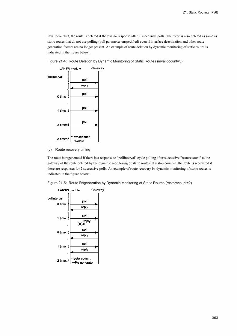
21. Static Routing (IPv6)
invalidcount=3, the route is deleted if there is no response after 3 successive polls. The route is also deleted as same as static routes that do not use polling (poll parameter unspecified) even if interface deactivation and other route generation factors are no longer present. An example of route deletion by dynamic monitoring of static routes is indicated in the figure below.
Figure 21-4: Route Deletion by Dynamic Monitoring of Static Routes (invalidcount=3)
(c) Route recovery timing
The route is regenerated if there is a response to "pollinterval" cycle polling after successive "restorecount" to the gateway of the route deleted by the dynamic monitoring of static routes. If restorecount=3, the route is recovered if there are responses for 2 successive polls. An example of route recovery by dynamic monitoring of static routes is indicated in the figure below.
Figure 21-5: Route Regeneration by Dynamic Monitoring of Static Routes (restorecount=2)
363

21. Static Routing (IPv6)
21.2 Configuration
21.2.1 List of Configuration CommandsThe following table provides a list of static routing (IPv6) configuration commands.
Table 21-2: List of Configuration Commands
21.2.2 Setting Default RouteSet a default route for static routing.
[Point of setting]Use the command ipv6 route to configure static route. A default route is configured by specifying ::/0 as prefix.
[Setup using commands]
1. (config)# ipv6 route ::/0 2001:db8:1:1::2
Specifies remote gateway 2001:db8:1:1::2 as the next hop of the default route.
21.2.3 Setting Single-path RouteSet a single-path static route. Priority among multiple routes is adjusted by the distance value.
[Point of setting]For the static route to be set as alternative route, specify the distance value greater than the preferred route.
[Setup using commands]
1. (config)# ipv6 route 2001:db8:ffff:1::/64 2001:db8:1:2::2 100
Specifies remote gateway 2001:db8:1:2::2 as next hop for static route 2001:db8:ffff:1::/64. Specifies 100 for distance value.
2. (config)# ipv6 route 2001:db8:ffff:1::/64 fe80::2 vlan 10 200 noresolve
Specifies remote gateway fe80::2%vlan10 as next hop for static route 2001:db8:ffff:1::/64. Specify 200 for distance value. This is the alternate route when route to gateway 2001:db8:1:2::2 is disabled.
21.2.4 Setting Multipath RouteSet a multipath static route.
[Point of setting]Multipath can be configured by omitting the distance value or specifying the same distance value when configuring multiple static routes to the same destination with the ipv6 route command.
Command Description
ipv6 route Generates IPv6 static route.
ipv6 route static poll-interval Specifies the polling interval.
ipv6 route static poll-multiplier Specifies the polling times and successive response times.
364

21. Static Routing (IPv6)
[Setup using commands]
1. (config)# ipv6 route 2001:db8:ffff:2::/64 2001:db8:2:1::2 noresolve
Specifies neighboring gateway 2001:db8:2:2::1 as next hop for static route 2001:db8:ffff:2::/64.
2. (config)# ipv6 route 2001:db8:ffff:2::/64 2001:db8:2:2::2 noresolve
Specifies neighboring gateway 2001:db8:2:2::2 as next hop for static route 2001:db8:ffff:2::/64. Static route 2001:db8:ffff:2::/64 forms a multipath between neighboring gateway 2001:db8:2:1::2 and 2001:db8:2:2::2.
21.2.5 Applying Dynamic Monitoring FunctionApply the dynamic monitoring function for static route after adjusting the polling interval and route delete/generate timing of the monitored gateway.
[Point of setting]Use the ipv6 route static poll-interval and ipv6 route static poll-multiplier command to set the polling interval and count. Specify the poll parameter with the ipv6 route command to use dynamic monitoring function for static route.
[Setup using commands]
1. (config)# ipv6 route static poll-interval 10
Specifies 10 seconds for the polling interval of the dynamic monitoring function.
2. (config)# ipv6 route static poll-multiplier 4 2
Specifies 4 for successive failure times (invalidcount), and 2 for successive response times (restorecount) of the dynamic monitoring function.
3. (config)# ipv6 route 2001:db8:ffff:3::/64 2001:db8:3:1::2 poll
(config)# ipv6 route 2001:db8:ffff:4::/64 2001:db8:3:1::3 poll
Enables dynamic monitoring function on static routes 2001:db8:ffff:3::/64 and 2001:db8:ffff:4::/64.
365

21. Static Routing (IPv6)
21.3 Operation
21.3.1 List of Operation CommandsThe following table provides a list of static routing (IPv6) operation commands.
Table 21-3: List of Operation Commands
21.3.2 Checking Route InformationCheck the static route information.
Figure 21-6: Execution Result of show ipv6 static route Command
>show ipv6 static routeDate 2005/07/14 12:00:00 UTCStatus Codes: * valid, > active Destination Next hop Distance Weight Status Flag ::/0 2001:db8:1:1::2 2 0 IFdown -*> 2001:db8:ffff:1::/64 2001:db8:1:2::2 100 0 Act -* 2001:db8:ffff:1::/64 fe80::2%VLAN0010 200 0 Act NoResolve*> 2001:db8:ffff:2::/64 2001:db8:2:1::2 2 0 Act NoResolve 2001:db8:2:2::2 2 0 Act NoResolve*> 2001:db8:ffff:3::/64 2001:db8:3:1::2 2 0 Act Reach Poll 2001:db8:ffff:4::/64 2001:db8:3:1::3 2 0 Unreach Poll
[Point of checking]
Command Description
ping ipv6 Sends test packet to the system at specified IPv6 address to determine whether communication is enabled.
show ipv6 interface Displays the IPv6 interface state.
show netstat(netstat)(IPv6) Displays the state and statistics of a network.
traceroute ipv6 Displays route to destination host traveled by IPv6 datagram.
dump protocols unicast Outputs the trace information and control table information collected by a unicast routing program to a file.
erase protocol-dump unicast Deletes the trace information file and control table information file created by a unicast routing program.
restart unicast Restarts the unicast routing program.
show ipv6 interface ipv6-unicast Displays the IPv6 interface information of the LANSW module recognized by a unicast routing program.
clear ipv6 route Clears and re-enters IPv6 forwarding entry in hardware.
show ipv6 entry Displays detailed information on specific IPv6 unicast route.
show ipv6 route Displays the route information held in the routing table.
show ipv6 static Displays information on static route.
clear ipv6 static-gateway Polls the gateway of a route invalidated by the dynamic monitoring of a static route and creates a route if a response is made.
366

21. Static Routing (IPv6)
1. For the route set in the routing table, "*" and ">" are displayed as Status Codes at the head of line.2. For the alternative route not set in the routing table, ">" is not displayed as Status Codes, but "*" is displayed if
it is a valid route.3. For the invalid route for which "*" and ">" are not displayed as Status Codes, some failure cause is displayed
as Status. "IFdown" indicates that the route becomes invalid because of interface failure. "UnReach" indicates that reachability is not confirmed by dynamic monitoring function.
21.3.3 Checking Gateway InformationChecks the static route gateway information.
Figure 21-7: Execution Result of show ipv6 static gateway Command
>show ipv6 static gatewayDate 2005/07/14 12:00:00 UTCGateway Status Success Failure Transition2001:db8:1:1::2 IFDown - - -2001:db8:1:2::2 - - - -2001:db8:2:1::2 - - - -2001:db8:2:2::2 - - - -2001:db8:3:1::2 Reach - 0/4 13m 39s2001:db8:3:2::2 UnReach 1/2 - 21sfe80::3%VLAN0010 - - - -
[Point of checking]1. For the gateway subject to dynamic monitoring, the reachability state is displayed as Status. If the reachability
is confirmed, "Reach" is displayed, and if not, "UnReach" is displayed.2. When the reachability is not confirmed ("UnReach" is displayed as Status), confirm the monitoring status of the
gateway by Success counter. In the execution result above, the Success counter of gateway 2001:db8:3:2::2 is displayed as "1/2". This means that the reachability is confirmed by successive 2 responses and one response has succeeded at present.
367

21. Static Routing (IPv6)
368

22. RIPng
22RIPngThis chapter provides a general description of IPv6 routing protocol RIPng.
22.1 RIPng Overview
22.2 Configuration
22.3 Operation
369
22. RIPng
22.1 RIPng Overview
22.1.1 Outline of RIPngRIPng is the routing protocol used between routers on the same network. Each one of the routers creates routing information by mutually notifying of the network that can be reached from the local router using RIPng and the number of hops (metric) to that network. The router supports RIPng in version 1 (RFC2080 compliant).
(1) Type of messages
RIPng uses two message types: request and response. Request is used when a router requests routing information from other routers and response is used when a router responds to other routers and notifies them of local router's route information periodically or when there is a change in topology.
(2) Processing during operation
When the LANSW module begins operating, it requests all available route information from each neighboring router. During operation, the LANSW module sends response at following three timing.
• When it receives request from a neighboring router, it responds by returning the route information it has depending on the request content.
• This is the periodic notification of route information. The LANSW module notifies neighboring routers by transmitting a response including all available route information, every 30 seconds.
• At the notification of route information that is performed when the change in a route is detected. When there is a change in route, the LANSW module notifies the neighboring router of the change by transmitting a response including the information related to the changed route.
Each neighboring router updates its route information when it receives a transmitted response and detects the change in a route. The response is also used to confirm the transmission to the neighboring router. A router which does not reply to a response for more than 180 seconds is judged to be incapable of communication. When an alternate route exists, the routing table is updated to the alternate route. A route is deleted when no alternate route exists.
(3) Suppression of routing loop
The LANSW module uses split horizon to suppress relay route loops. With split horizon, the received information is not transmitted back to the interface that originally received the information.
(4) Difference in Function between RIPng (IPv6) and RIP (IPv4)
The following table shows the difference in function between RIPng (IPv6) and RIP (IPv4).
Table 22-1: Functional Difference between RIPng (IPv6) and RIP (IPv4)
Function RIPng (IPv6) RIP (IPv4)
triggered update Y Y
Split horizon Y Y
Route Poisoning Y Y
Poison reverse N N
Hold down N N
Route tag Y Y
Read specified next hop Y Y
370

22. RIPng
(Legend) Y: Handled N: Not handled
22.1.2 Route Selection CriteriaThe LANSW module selects the best route to the same destination learned by each protocol according to independent route selection procedure. When multiple routes to the same destination exists, the distance value for each routing protocol is compared. The routing protocol with the highest priority is selected.
With RIPng, the best route is selected according to the route selection priority from route information to the same destination with different advertising source learned using its own protocol. The route selection priority is shown in the table below.
Table 22-2: Route Selection Priority
* This condition is used to learn route information for which the next hop address in the route information is the same from different neighboring systems within the same network.
Then, when multiple route information items to the same destination exist in the route learned by each protocol (OSPFv3, BGP4+, and static), the distance value of each route information is compared. The route information with higher priority is set to the routing table.
(1) Secondary route generation
Up to two routes (primary route and secondary route) to the same destination learned from different neighboring systems are generated by specifying configuration command generate-secondary-route. The table below shows the condition for generating secondary route.
Table 22-3: Conditions of Secondary Route Generation
(Legend) Y: Configuration available N: Configuration unavailable -: Not applicable
Authentication function N N
If the aging time of the existing route has elapsed by 1/2 second or greater when a route of the same metric as the existing route is received from a different gateway, the former route is changed to a newly learned route.
N Y
Precedence Contents
High↑
↓Low
Selects the route with the smallest metric value.
Selects the route with the smallest next hop address.
Selects route for which the next hop address in the route information match the source gateway address of the route information.*
In cases other than the above, ignores the newly learned route.
Condition Secondary Route Generation
Setting of Configuration Command generate-secondary-route
Distance Value
N - Not generated
Y Value of primary route and secondary route differs
Not generated
Y Values of primary route and secondary route are the same
Generated
Function RIPng (IPv6) RIP (IPv4)
371

22. RIPng
When generation of secondary route is specified, the priority of route information to the same destination is determined according to the following table.
Table 22-4: Route Selection Priority When Registration of Secondary Route Is Specified
NoteWhen the next hop address is the same, only the primary route is generated.
*1This condition does not apply when a new route is learned with the secondary route registered.
*2This condition is used to learn route information for which the next hop address in the route information is the same from different neighboring systems within the same network.
22.1.3 Advertising Route Information
(1) Route subject to advertisement
(a) Learning source protocol
For RIPng, learned RIPng routes and direct-connection routes on RIPng-operating interface are advertised when a route advertisement filter is not set. When a route advertisement filter is set, advertisement is executed according to the corresponding filtering operation. Table below lists the learning protocols subject to the advertisement for RIPng.
Table 22-5: Learning Source Protocol to Be Advertised
*1
Precedence Contents
High↑
↓Low
Selects the route with small metric value.
Selects a route with small next hop address.*1
Selects route for which the next hop address in the route information match the source gateway address of the route information.*2
Selects the route that was the primary route.
In cases other than the above, ignores the newly learned route.
Learning Source Protocol Advertisement Operation without
Route Advertisement Filter Setting
Order in Which Advertised Metric Is Applied*5
Direct-connection route*1
Interface where RIPng operates
Advertised 1. Value specified for route advertisement filter2. Default (metric: 1)
Interfaces other than those where RIPng operates
Not advertised
Aggregate route Not advertised
Static route Not advertised 1. Value specified for route advertisement filter2. Value specified for default-metric3. Default (metric: 1)
RIPng*2 Advertised 1. Value specified for route advertisement filter2. Value in routing table
OSPFv3 Not advertised 1. Value specified for route advertisement filter2. When inherit-metric is set, value in routing table*3
3. Value specified for default-metric*4BGP4+ Not advertised
372

22. RIPng
Secondary address is also advertised.
*2Split horizon is applied.
*3When metric value in the routing table is 16 or greater, the route is not advertised.
*4When route advertisement filter is not specified or metric is not specified in inherit-metric or default-metric, the route is not advertised.
*5When metric-offset out command is set, the value specified for metric-offset out command is added to the selected metric value. When metric value becomes 16 or greater as a result of addition, the route is not advertised.
(b) Address type
The following table shows the address type advertised with RIPng.
Table 22-6: Route Information Type
(Legend) Y: Advertisement enabled* Only global address and site local address can be advertised.
(2) Destination of route information advertisement
RIPng advertises route information to all neighboring routers (including routers on the network containing interface secondary address) connected to the interface specifying the configuration command ipv6 rip enable.
(3) Advertisement timing of route information
The timing of route advertising with RIPng is related to the functions shown in the following table.
Table 22-7: Timing of Route Advertisement
(a) Periodic route information advertisement
RIPng broadcasts its routing table to its neighboring routers. The figure below shows an example of periodic route information advertisement.
Route Information Type Definition Example Advertisement Enabled/Disabled
Default route information Route information to all networks. ::/0 Y
Network route information Global route information to the specific network
2001:db8:1:1::/642001:db8:1::/56
Y*
Host route information Global route information to specific host 2001:db8:1:1::1/128 Y*
Function Contents
Periodic Route Information Advertisement Periodically notifies local system's route information to neighboring router.
triggered update Performs notification without waiting for periodic advertising when there is a change in route information in the local system.
Response to the request from neighboring router Performs notification to the neighboring router which sent the request packet.
Route Poisoning Notifies the neighboring routers for a certain period that the route information is deleted.
373

22. RIPng
Figure 22-1: Periodic Route Information Advertisement
(b) triggered update
Distributes the route information without waiting for the periodic distribution interval when recognizing change in the local system's route information. The following figure shows the advertisement of route information by triggered update.
Figure 22-2: Route Broadcasting through Triggered Update
(c) Response to request packet
When receiving the request packet, the LANSW module notifies the route information to the neighboring router which sent that packet. The following figure shows the advertisement of route information due to receiving of request packet.
374
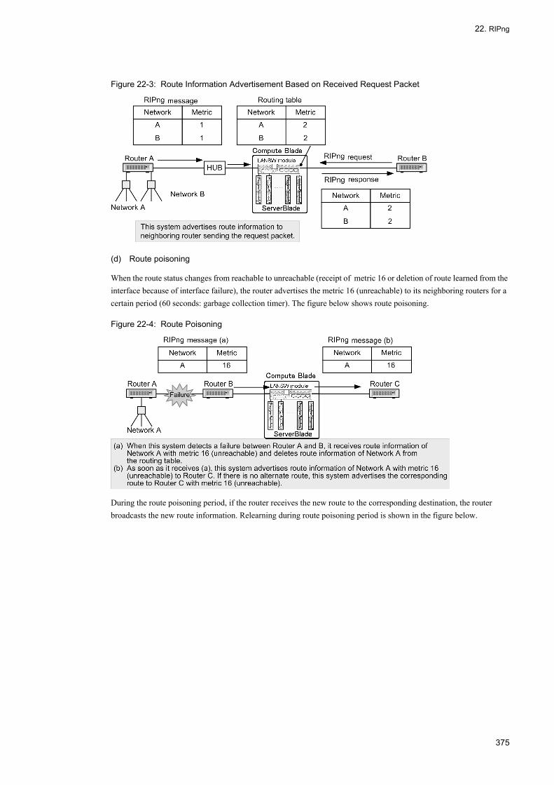
22. RIPng
Figure 22-3: Route Information Advertisement Based on Received Request Packet
(d) Route poisoning
When the route status changes from reachable to unreachable (receipt of metric 16 or deletion of route learned from the interface because of interface failure), the router advertises the metric 16 (unreachable) to its neighboring routers for a certain period (60 seconds: garbage collection timer). The figure below shows route poisoning.
Figure 22-4: Route Poisoning
During the route poisoning period, if the router receives the new route to the corresponding destination, the router broadcasts the new route information. Relearning during route poisoning period is shown in the figure below.
375
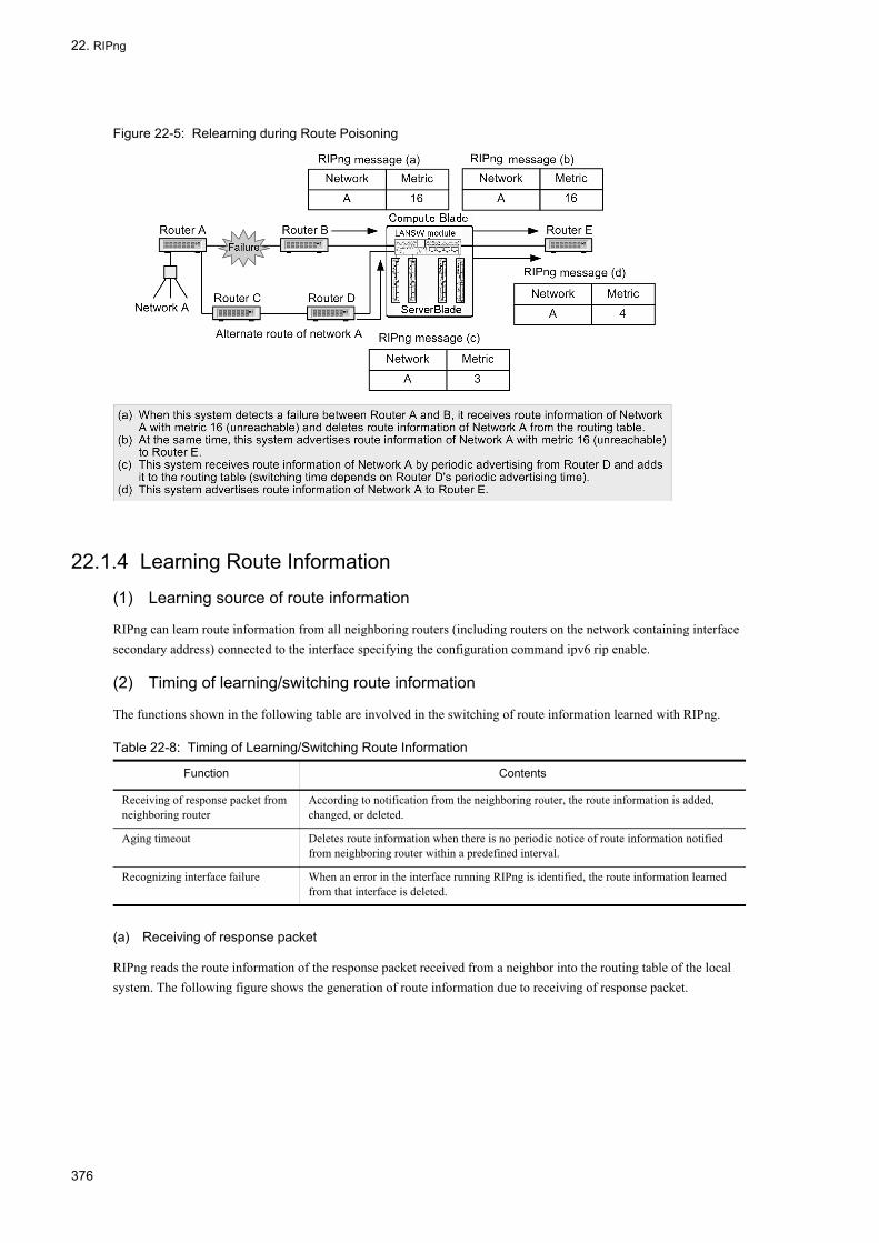
22. RIPng
Figure 22-5: Relearning during Route Poisoning
22.1.4 Learning Route Information
(1) Learning source of route information
RIPng can learn route information from all neighboring routers (including routers on the network containing interface secondary address) connected to the interface specifying the configuration command ipv6 rip enable.
(2) Timing of learning/switching route information
The functions shown in the following table are involved in the switching of route information learned with RIPng.
Table 22-8: Timing of Learning/Switching Route Information
(a) Receiving of response packet
RIPng reads the route information of the response packet received from a neighbor into the routing table of the local system. The following figure shows the generation of route information due to receiving of response packet.
Function Contents
Receiving of response packet from neighboring router
According to notification from the neighboring router, the route information is added, changed, or deleted.
Aging timeout Deletes route information when there is no periodic notice of route information notified from neighboring router within a predefined interval.
Recognizing interface failure When an error in the interface running RIPng is identified, the route information learned from that interface is deleted.
376

22. RIPng
Figure 22-6: Route Information Generation Based on Received Response Packet
(b) Aging timeout
If the route information generated by receiving of response packet is the best route, it is read into the routing table of the local system. The read route information is monitored using an aging timer. The aging timer is reset (cleared) by the periodical advertisement from a neighboring system. The relevant route information is deleted from the routing table of the local system when it is not advertised from the neighboring system for 180 seconds (aging timeout value) due to the failure of a neighboring router or the line trouble between a local system and neighboring router. Deletion of route information through aging timeout is shown in the figure below.
Figure 22-7: Route Information Deletion Due to Aging Timeout
(c) Recognizing interface failure
When recognizing a failure in local system's interface connected to the neighboring router, the LANSW module deletes all route information learned from that interface. Deletion of route information due to interface failure is shown in the figure below.
377

22. RIPng
Figure 22-8: Route Information Deletion Due to Interface Failure
22.1.5 RIPng FunctionsRIPng can handle the variable prefix length so as to set the prefix length of the corresponding route to the advertised path information. The major functions of RIPng are as follows.
(1) Authentication function
The LANSW module does not support authentication function.
(2) Route tag
In the LANSW module, when a response message notifies the route of the route tag, the route tag is put into the routing table. For the route tag information of routing information of the response message to be notified by the LANSW module, set the route tag of the corresponding route in the routing table. The usable range is 1 to 65535 (decimal).
RIPng does not support filtering of route tags with import filter or alteration of route tags with export filter (distributing route to RIPng from other protocol).
(3) Prefix
The LANSW module loads the prefix length of path information reported using a response message into the routing table. The path information's prefix length of a response message that is reported from the LANSW module sets the prefix length of the corresponding path in the routing table.
(4) Next hop
With the LANSW module, when the next hop information of the route information notified by the response message is set, the next hop information is entered into the routing table. When the next hop is not set, the source gateway is recognized as the next hop.
In the response message reported from the LANSW module, the next hop information of path information is not set. Therefore, a router that receives a path from the LANSW module using RIPng uses the interface address of a transmission interface as a next hop.
(5) Use of link local multicast address
The LANSW module supports a link local multicast address so as to reduce the unnecessary load in a host that receives no RIPng message. The link local multicast address used during transmission of a RIPng message is a total RIPng router multicast address (ff02::9).
378

22. RIPng
22.1.6 NotesPay attention to the limitations below when configuring a network in which RIPng is used.
(1) Deviations from RFC
The LANSW module conforms to RFC2080 (RIPng version 1), but it is partially different from RFC due to software function limitation. The deviation from RFC is shown in the table below.
Table 22-9: Deviations from RFC2080
RFC The LANSW module
must be zero field Processing is not specifically described. The LANSW module does not check the value of a "must be zero" field. During transmission, the "must be zero" field is set to "0".
Network prefix The address field state after prefix length is not specifically described.
The address after prefix length is zero-cleared when the path information is received in which the address field after the prefix length is not zero-cleared using received RIPng packets.
triggered update After a triggered update occurs, a 1 to 5 sec random timer should be set; and even if a change is made that sends an update before a timeout occurs, update is performed at the time of a timeout.
After a triggered update occurs, no 1-5 sec random timer is set; and when a change is made to the route information, a triggered update is performed as needed.
When a normal update is performed during activation of a 1 to 5 sec random timer after a triggered update occurs, triggered update may be inhibited.
Inhibition of triggered update is not performed.
Split horizon A split horizon function should be able to change the setting in units of interfaces.
The LANSW module does not support the change in setting in units of the split horizon function's interfaces.
Next hop information setting of route
The next hop information in a path can be specified explicitly.
No next hop information is contained in the RIPng packets sent from the LANSW module. If the LANSW module receives the RIPng packets in which next hop information is explicitly specified, the value is used as next hop information.
Destination of response packet
For ff02::9, the improper case (e.g., NBMA network) depends on the implementation.
The LANSW module does not support the RIPng operation in an NBMA network.
Authentication Packets are authenticated using an IPv6 authentication header and enciphered header.
The LANSW module does not support packet authentication using an IPv6 authentication header and enciphered header.
Return of response packets at the time of reception of request packets coming from other than source port 521 via unicast
Response packets can be returned directly to the source address.
The system returns response packets to only request packets where a link local address is specified for source address.
379

22. RIPng
22.2 Configuration
22.2.1 List of Configuration CommandsThe following table provides a list of RIPng configuration commands.
Table 22-10: List of Configuration Commands
22.2.2 Applying RIPngSet the interface to transmit RIPng packets.
[Point of setting]Use the ipv6 rip enable command to apply RIPng.
[Setup using commands]
1. (config)# interface vlan 10
(config-if)# ipv6 address 2001:db8:1:1::1/64
Assigns IPv6 address 2001:db8:1:1::1/64 to interface vlan 10.
2. (config-if)# ipv6 rip enable
Enables transmitting of RIPng packets on interface vlan 10.
3. (config-if)# exit
(config)# interface vlan 20
(config-if)# ipv6 address 2001:db8:1:2::1/64
Assigns IPv6 address 2001:db8:1:2::1/64 to interface vlan 20.
Command Description
default-metric Specifies the metric value when advertising the route information learned using other protocols by RIPng.
disable Disables RIPng.
distance Specifies the distance value of the route information learned by RIPng.
distribute-list in (RIPng) Uses a filter to control whether to read the route learned by RIPng into the routing table.
distribute-list out (RIPng) Uses a filter to control the route advertised by RIPng.
generate-secondary-route Registers the second-highest priority route in the routing table.
inherit-metric Specifies that a metric value is inherited when advertising the route information of other routing protocols using RIPng.
ipv6 rip enable Transmits RIPng packets on the specified interface.
ipv6 rip metric-offset Specifies the value to be added to the metric when transmitting RIPng packets on the specified interface.
ipv6 router rip Sets RIPng related operating information.
passive-interface Specifies not to transmit route information with RIPng packets from the specified interface.
redistribute Specifies the protocol type of route advertised by RIPng.
timers basic Specifies the various RIPng timer values.
route-map Sets route-map.
ipv6 prefix-list Sets IPv6 prefix-list.
380

22. RIPng
4. (config-if)# ipv6 rip enable
Enables transmitting of RIPng packets on interface vlan 20.
5. (config-if)# exit
22.2.3 Setting Metric
(1) Configuring metric when advertising route information other than RIPng
Set the metric value when advertising RIPng route information learned by other protocols.
[Point of setting]When advertising OSPFv3 route or BGP4+ route by RIPng, metric must be set by configuration. Use default-metric command to set the metric value.
[Setup using commands]
1. (config)# ipv6 router rip
(config-rtr-rip)# default-metric 10
Sets the metric value 10 when advertising RIPng route information learned by other protocols.
2. (config-rtr-rip)# redistribute static
Sets to advertise static route by RIPng.
3. (config-rtr-rip)# redistribute ospf
Sets to advertise OSPFv3 route by RIPng.
(2) Setting of the value to be added to metric value when sending/receiving packets
Set the value to be added to metric value when transmitting RIPng packets.
[Point of setting]Use the ipv6 rip metric-offset command to set the value to be added to the metric value of a route transmitted over a specific interface.
[Setup using commands]
1. (config)# interface vlan 10
(config-if)# ipv6 rip metric-offset 2 out
Sets to add 2 to the metric value of RIPng packet sent from interface vlan 10.
22.2.4 Adjusting TimerAdjust the RIPng periodic advertisement timer, aging timer, and the time to delete from the routing table.
To reduce convergence time when changing the route, set periodic advertisement timer value and aging timer value smaller than the default value. Sets the periodic advertisement timer larger than the default value if you need to reduce the periodic RIPng advertisement traffic.
When changing the RIPng timer value, use the same timer value on all routers in the RIPng network.
381

22. RIPng
[Point of setting]Use the timers basic command to change the RIPng timer value.
[Setup using commands]
1. (config)# ipv6 router rip
(config-rtr-rip)# timers basic 40 200 100
Sets the RIPng periodic advertisement timer to 40 seconds, aging timer to 200 seconds, and the time to delete from the routing table to 100 seconds.
382

22. RIPng
22.3 Operation
22.3.1 List of Operation CommandsThe following table shows a list of operation commands used to check RIPng information.
Table 22-11: List of Operation Commands
22.3.2 Checking RIPng Operation StatusDisplay RIPng protocol information.
Figure 22-9: Execution Result of show ipv6 rip Command
> show ipv6 ripDate 2005/07/14 12:00:00 UTCRIPng Flags: <ON>Default Metric: 10, Distance: 120Timers (seconds) Update : 40 Aging : 200 Garbage-Collection : 100
22.3.3 Checking Destination InformationDisplay RIPng destination information.
Command Description
show ipv6 interface Displays the IPv6 interface state.
show netstat (netstat) (IPv6) Displays the state and statistics of a network.
show processes cpu unicast Displays the CPU usage of the unicast routing program.
debug protocols unicast Starts operation message display of the event log information that a unicast routing program outputs.
dump protocols unicast Outputs the trace information and control table information collected by a unicast routing program to a file.
erase protocol-dump unicast Deletes the trace information file and control table information file created by a unicast routing program.
no debug protocols unicast Stops operation message display of the event log information that the unicast routing program outputs.
show ipv6 interface ipv6-unicast Displays the IPv6 interface information of the LANSW module recognized by a unicast routing program.
debug ipv6 Displays packet exchanged by IPv6 routing protocol in real time.
clear ipv6 route Clears and re-enters IPv6 forwarding entry in hardware.
show ipv6 entry Displays detailed information on specific IPv6 unicast route.
show ipv6 route Displays the route information held in the routing table.
show ipv6 rip Displays RIPng protocol information.
clear counters rip ipv6-unicast Clears the information on the RIPng protocol.
383

22. RIPng
Figure 22-10: Execution Result of show ipv6 rip target Command
> show ipv6 rip targetDate 2005/07/14 12:00:00 UTCSource Address Destination Flagsfe80::4048:47ff:fe10:1%VLAN0010 VLAN0010 <Multicast>fe80::4048:47ff:fe10:1%VLAN0020 VLAN0020 <Multicast>
22.3.4 Checking Learned Route Information
(1) Checking for each network
Display route information learned by RIPng included in the specified network.
Figure 22-11: Execution Result of show ipv6 rip route Command
> show ipv6 rip route brief 4001::/16Date 2005/07/14 12:00:00 UTCStatus Codes: * valid, > active Destination Interface Metric Tag Timer*> 4001:21f7:2910:3029::/64 VLAN0010 3 0 4s*> 4001:64b9:4ba6:dd65::/64 VLAN0020 4 0 10s*> 4001:652c:7a78:c37::/64 VLAN0020 3 0 9s*> 4001:ddd9:158:9a2f::/64 VLAN0010 5 0 4s
(2) Checking for each gateway
Display by gateway, route information received by RIPng included in the specified network.
Figure 22-12: Execution Result of show ipv6 rip received-routes Command
> show ipv6 rip received-routes brief 4001::/16Date 2005/07/14 12:00:00 UTCStatus Codes: * valid, > activeNeighbor Address: fe80::4048:47ff:fe10:10%VLAN0010 Destination Interface Metric Tag Timer*> 4001:21f7:2910:3029::/64 VLAN0010 3 0 9s*> 4001:ddd9:158:9a2f::/64 VLAN0010 5 0 9sNeighbor Address: fe80::4048:47ff:fe10:20%VLAN0020 Destination Interface Metric Tag Timer*> 4001:64b9:4ba6:dd65::/64 VLAN0020 4 0 15s*> 4001:652c:7a78:c37::/64 VLAN0020 3 0 14s
22.3.5 Checking Advertised Route InformationDisplay the route information sent to the specified interface.
Figure 22-13: Execution Result of show ipv6 rip advertised-routes Command
> show ipv6 rip advertised-routes brief interface vlan 10Date 2005/07/14 12:00:00 UTCTarget Interface: VLAN0010Destination Interface Metric Tag Age*> 2001:db8:1:2::/64 VLAN0020 1 0 22m 37s*> 4001:64b9:4ba6:dd65::/64 VLAN0020 5 0 21s*> 4001:652c:7a78:c37::/64 VLAN0020 4 0 20s
384

23. OSPFv3
23OSPFv3 This chapter describes OSPFv3 which is a routing protocol used mainly for intranet.
23.1 OSPFv3 Basic Function Overview
23.2 Configuration of OSPFv3 Basic Function
23.3 Interface Overview
23.4 Configuration of Interface
23.5 Operation of OSPFv3
385

23. OSPFv3
23.1 OSPFv3 Basic Function Overview
OSPFv3 is a routing protocol for IPv6 based on the topology constituted by the connection state between routers and the shortest path calculation using the Dijkstra algorithm.
23.1.1 Features of OSPFv3OSPFv3 is usually used to determine the route in one AS. In OSPFv3, the database of topology constituted from all connection states in AS is provided in each router. The shortest path is calculated based on this database. Therefore, OSPFv3 has the features below as compared with RIPng.
• Deletion of route information trafficIn OSPFv3, the connection state information is transmitted to other routers only when the connection state between routers changes. Therefore, with OSPFv3, the traffic attributed to routing protocol is smaller compared to routing protocol that periodically notifies all route information such as in RIPng. In OSPFv3, a local router's connection state information is transmitted to other routers every 30 minutes.
• Suppression of routing loopAll routers that use OSPFv3 store a database consisting of the same data. Each router selects a route according to the common data. Therefore, no routing loop (circulation of a relay route) occurs as in RIPng.
• Route selection by costIn OSPFv3, the route that is the lowest in total cost to the destination is selected when multiple routers that can reach the destination exist. Unlike RIPng, this enables the lowest cost to be set to a route. The desired route can be thus selected regardless of the number of relay stages.
• Operation of large-scale networkIn OSPFv3, a route of more than 65536 in cost is judged unreachable. Therefore, compared to RIPng which assumes routes with metric 16 or greater as unreachable, OSPFv3 is more suitable for large scale network with many routers in between.
23.1.2 OSPFv3 FunctionOSFPv3 is a protocol similar to OSPF, but OSPF and OSPFv3 operate independently of each other.
(1) Functional difference from OSPF
The difference between the function of OSPFv3 (IPV6) and OSPF (IPv4) is shown in the table below.
Table 23-1: Functional Difference between OSPFv3 (IPv6) and OSPF (IPv4)
Function OSPFv3 (IPv6) OSPF (IPv4)
Forwarding address of AS external path N Y
NSSA N Y
Authentication N Y
Non-broadcast (NBMA) network N Y
Equal cost multipath Y* Y
Virtual link Y Y
Multi-backbone Y Y
Helper function of graceful restart Y Y
Restart function of graceful restart N N
Stub router Y Y
386

23. OSPFv3
(Legend) Y: Handled N: Not handled
*The route selection method varies depending on OSPF (IPv4) and OSPFv3 (IPv6). For equal cost, in OSPF (IPv4), the minimum next hop address is selected. In OSPFv3 (IPv6), the next hop address in which router ID is minimum is selected. When multiple next hop addresses having the same router ID exist, the next hop address advertising minimum interface ID with Hello packet is selected.
(2) Domain
One single unit of the LANSW module, split AS into multiple OSPFv3 networks and exchange, calculate and create routes individually for each OSPFv3 network. This is referred to as the OSPFv3 multi-backbone function. This independent OSPFv3 network is referred to as OSPFv3 domain.
23.1.3 Route Selection AlgorithmOSPFv3 uses SPF (Shortest Path Find) as the route selection algorithm. Each router running OSPFv3 has a database containing information on all OSPFv3-operating routers and all connections between routers as well a between routers and networks. Topology is first constituted from this database with the router and network as a vertex and with the connection between routers and a router and network as a side. The SPF algorithm is applied to this topology so as to create the shortest path tree and the route to each vertex is determined based on the obtained information.
An example of network configuration is shown in the figure below.
Figure 23-1: Network Configuration Example
For the network shown in the figure above, a setting example of the topology and cost when OSPFv3 is used is shown below.
Figure 23-2: Setting Example of Topology and Cost
The cost value may vary depending on the direction of packet transmission. For the point-to-point connection between Router 2 and Router 4 in "Figure 23-2: Setting Example of Topology and Cost", the connection of Router 2 to Router 4
387

23. OSPFv3
is Cost 9, and the connection of Router 4 to Router 2 is Cost 8. For the connection between a router and network, the cost can be set only in the connection from a router to a network. For the connection from a network to a router, the cost is "0" at all times.
The figure below shows the shortest path tree created, with Router 1 as a root, according to the topology shown in "Figure 23-2: Setting Example of Topology and Cost". The cost is the total of transmission cost in each interface through which the path passes. For example, the cost of a path from Router1 to Network 2 is 6 (Route 1 - Network 1) + 0 (Network 1 - Router 3) + 2 (Router 3 - Network 2) = 8.
Figure 23-3: Shortest Path Tree with Router 1 as Root
23.1.4 Advertisement of LSA
(1) LSA type
In OSPFv3, route information is referred to as Link State Advertise (LSA).
The main LSA is divided into the following three types.
(a) Intra-area route information
Notifies the states of routers and networks used in SPF algorithm.
(b) Inter-area route information
Notifies another area's route.
(c) AS external route information
When an OSPFv3 router identifies an AS external route information, this route can be used to notify all other OSPFv3 routers. A router that implements AS external route within OSPFv3 is referred to as AS border router.
(2) AS external route
AS external route is advertised when a route redistribution filter is configured. The source AS boundary router advertises LSA with the following information added.
• MetricThe metric is used by a router learning the routes to select a route on the basis of comparison with other LSAs.Default value of metric is set by default-metric command.
• AS external path metric typeThere are two types, Type 1 and Type 2. In Type 1 and Type 2 routes, the priority level of a route and the calculation method when using metric for route selection differ. Default metric type is Type 2.
388

23. OSPFv3
• Forwarding address (forwarding destination)In the LANSW module, the forwarding address is not set.
• TagA tag can be advertised as additional information.
(3) AS external route advertising between domains
Multiple OSPFv3 domains connected by one router each operate as an independent OSPFv3 network. Therefore, if path redistribution is not configured, routes in one OSPFv3 domain are not distributed to the other OSPFv3 domain. If redistribution filter is configured for OSPFv3 route learned in another domain, the route in another domain is advertised as AS external route. Default value shown in the table below is applied to the filter attribute.
Table 23-2: Filter Attributes for Redistributing Route of Another Domain
23.1.5 Installation Example of AS External RouteThe figure below shows an example of the introduction of an AS external route using a backup line.
Figure 23-4: Example of Introducing AS External Route Using a Backup Line
In OSPFv3, packets are periodically exchange to detect the neighboring router. Therefore, a backup line is always put into the operation state so as to continuously exchange packets using this line when it is partially used as the topology of OSPFv3. To keep the backup line inactive while communication is not required on this line, the following settings must be made.
In the LANSW module A, operate OSPFv3 using a main line and set the static path to Network A in a backup line. Also set the distance value of the static route to a value greater (lower priority) than the distance value of OSPFv3 area internal route. This causes the AS internal route learned by OSPFv3 to be selected as the route to Network A. In case of primary line failure, AS internal route to the corresponding the LANSW module A is deleted and the static route is re-selected, but route information to Network A no longer remains in System C. To advertise the LANSW module A's information on the static route to Network A as an AS external route to System C, it is necessary to set a route redistribution configuration on the LANSW module A. As a result, the effective path information to Network A can be installed in OSPFv3 without exchanging Hello packets using a backup line even if a main line fails.
Attribute Default Value
AS External Route Intra-area and Inter-area Routes
Metric value Value set by default-metric command.If default-metric setting is omitted, 20.
Value set by default-metric command.If default-metric setting is omitted, 20.
Metric type AS external route Type 2.
Tag value Inherits the tag value of the route. Not advertised
389

23. OSPFv3
23.1.6 Route Selection CriteriaWith OSPFv3, SPF is calculated every time LSA is updated by LSA generation or learning. In SPF calculation, the route is selected based on SPF algorithm. The route is deleted if the destination becomes unreachable by SPF algorithm.
In the area border router, the route selection is performed individually in all areas to which a router belongs based on SPF algorithm.
In OSPFv3, each path is selected in the priority level shown in the table below. The priority cannot be changed.
Table 23-3: Route Selection Priority
(1) Distance value
When there are multiple routes to the same destination, the distance value for each route is compared and the route with the highest priority is selected.
OSPFv3 allows default distance value to be set for each domain. Different distance values can be set for AS external route, area internal route, and intra-area route.
23.1.7 Equal Cost MultipathIn OSPFv3, when an equal cost multipath and multiple next transfer destination routers exist from a local router to a certain destination, traffic can be dispersed by dispersing the transfer of packets to the destination to multiple next hops.
For AS internal route, the LANSW module selects multiple routes which have destination type (intra-area or inter-area route) and cost equal to those of learning source domain. Similarly, for an AS external route, multiple routes having the same learning source domain, AS external route type, cost, and metric are selected.
Maximum number of paths can be changed by maximum-paths command. The default is 4.
Precedence Selection Item Details
High↑
↓Low
Route Information Type For the AS internal route (area internal route or intra-area route), the AS external route of OSPFv3 has priority.
Learning source domain If routes exist in multiple domains, the route with the smallest distance value is selected. If the distance value is equivalent, it selects a route whose OSPFv3 domain number is the smallest.
Destination type of path • AS internal route: The area internal route has priority over an inter-area route.• AS external route: The route advertised by AS border router within an area has
priority over the route advertised by AS border router in another area.
AS external route type Metric type Type 1 AS external route has priority over Type 2.
Areas on AS external route For a router that is an area border, when the destination AS boundary router connects to multiple areas, the area with the smallest cost to the AS boundary router is selected.When the cost is equal, the area with the largest area ID is selected.
Cost • AS internal route: The route in which the cost value to the destination is lowesthas priority.
• AS external route of Type 1: Selects the route in which the metric value of ASexternal route information and the cost value to an AS border router is lowestin total.
• AS external route of Type 2: Selects the route in which the metric value of ASexternal route information is lowest. Selects a route in which the cost value toan AS border router is lowest when the metric value is equal.
Router ID The route in which the router ID of a next hop router is lowest is selected.
Interface ID The interface in which the lowest interface ID is learned using Hello packets is selected from a next hop router.
390

23. OSPFv3
23.1.8 Notes
(1) Notes on router ID
In OSPFv3, router ID is used for identification of a router when constructing the topology of a network.
A route cannot be accurately selected when a router ID of the same value is defined in a different router during the design of a network. To avoid this problem, assign a router ID, which does not overlap, to each router during the design of a network.
When a single router is connected to multiple OSPFv3 domains, the same router ID may be used on all domains without any problem.
(2) Notes on route redistribution filter and learning filter
With OSPFv3, all LSAs learned from a neighboring router are advertised to other neighboring router.
Advertisement of route learned by OSPF in the same domain cannot be suppressed with redistribution filter. Also, when aggregating OSPFv3 routes using the route aggregation function (ipv6 summary-address command), LSA advertisement within the same domain cannot be suppressed even if suppression of aggregation source route advertisement is configured.
The distribute-list in command can suppress learning of AS external route satisfying the filter conditions. However, learning and advertisement of LSA cannot be suppressed. Therefore, unlearned routes are also advertised with OSPFv3.
(3) Notes on using multi-backbone function
(a) Note on using multi-backbone
When a network is divided into multiple OSPFv3 domains for operation, the features of OSPFv3, such as the route selection based on the suppression or cost of a routing loop, are lost by the selection or distribution of a route between domains. It is recommended to construct the network as a single OSPFv3 network when constructing a new network, that is, it is not necessary to divide a network into multiple OSPFv3 domains for operation.
(b) Notes on setting multiple domains
Advertise it as an OSPFv3 AS external path when it is necessary to advertise a system address to multiple OSPFv3 domains. A single interface cannot be configured concurrently for multiple OSPFv3 domains.
Up to four OSPFv3 domains can be configured.
(4) Restriction on OSPFv3
The LANSW module conforms to RFC2740 (OSPF for IPv6). However, the LANSW module does not support the functions below because of the limited software functions.
• Route selection based on the forwarding address of AS external route• Non-broadcast (NBMA) network
391

23. OSPFv3
23.2 Configuration of OSPFv3 Basic Function
23.2.1 List of Configuration CommandsThe following table provides a list of OSPFv3 basic function configuration commands.
Table 23-4: List of Configuration Commands Related to OSPFv3 Application
Table 23-5: List of Configuration Commands Related to AS External Route
Table 23-6: List of Configuration Commands Related to Route Selection and Route Learning
23.2.2 Flow of Configuring
(1) Configuration procedure of OSPFv3 basic function
1. First, configure the IPv6 resources with the swrt_table_resource command.This is necessary in order to perform IPv6 routing.
2. Configure the IPv6 interface in advance.
3. Configure to use OSPFv3.
4. Make settings for advertisement of AS external route.Configuration is necessary when advertising other protocol's routes with OSPFv3.Also, configuration is necessary when redistributing routes between domains using multi-backbone function.
5. Make settings for selecting route.Set the cost value with ipv6 ospf const command when preference must be given to routes passing through certain interface.
23.2.3 Setting for Applying OSPFv3[Point of setting]
Command Description
disable Suppresses operation of OSPFv3.
ipv6 ospf area Sets the OSPFv3 domain number and area ID.
router-id Sets router ID (identifier of the router).
Command Description
default-metric As metric to the destination, sets the fixed value.
distribute-list out Sets the redistribution filter to control the route to be advertised.
redistribute Sets the redistribution filter to advertise AS external route.
Command Description
distance Sets the OSPFv3 route distance value.
distribute-list in Sets suppression of learning AS external route.
ipv6 ospf cost Sets cost value.
maximum-paths Sets the maximum number of paths for equal cost multipath.
timers spf Sets the delay time and execution interval from LSA generation and learning to SPF calculation.
392

23. OSPFv3
• When router ID is omitted, loopback address is used as router ID. OSPFv3 will not operate if no loopback address is configured.
• Exchange LSA with neighboring router on interface specified with the ipv6 ospf area command.• If there is no area division, use the same area ID on all OSPFv3 routers.
[Setup using commands]
1. (config)# ipv6 router ospf 1
Enters ospfv3 mode. Sets the domain number to 1.
2. (config-rtr)# router-id 100.1.1.1
(config-rtr)# exit
Uses 100.1.1.1 as router ID.
3. (config)# interface vlan 1
(config-if)# ipv6 ospf 1 area 0
Specifies to operate in area 1 of domain 0.
23.2.4 Setting AS External Route Advertisement[Point of setting]
• redistribute command can set the information to be added to redistributed route (metric value, tag, and metric type). If metric value is omitted in redistribute command, the value set in default-metric command becomes invalid.
• For routes learned by OSPFv3, redistribution of routes within the same domain cannot be controlled.
[Setup using commands]
1. (config)# ipv6 router ospf 1
(config-rtr)# default-metric 10
Sets the default metric to 10.
2. (config-rtr)# redistribute static
Advertises the static route with the above default metric value.
23.2.5 Setting Route Selection[Point of setting]
Set the cost with the ipv6 ospf cost command for each interface.If 1 is set in maximum-paths command, equal cost multipath is not established even though the cost values of the routes are equal.A configuration example using a single path route is shown.
[Setup using commands]
1. (config)# ipv6 router ospf 1
(config-rtr)# maximum-paths 1
(config-rtr)# exit
Sets OSPFv3 maximum number of paths to 1.
2. (config)# interface vlan 1
393
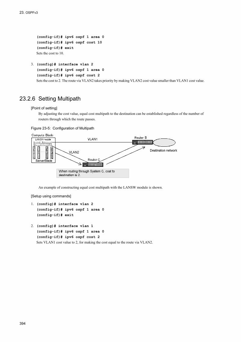
23. OSPFv3
(config-if)# ipv6 ospf 1 area 0
(config-if)# ipv6 ospf cost 10
(config-if)# exit
Sets the cost to 10.
3. (config)# interface vlan 2
(config-if)# ipv6 ospf 1 area 0
(config-if)# ipv6 ospf cost 2
Sets the cost to 2. The route via VLAN2 takes priority by making VLAN2 cost value smaller than VLAN1 cost value.
23.2.6 Setting Multipath[Point of setting]
By adjusting the cost value, equal cost multipath to the destination can be established regardless of the number of routers through which the route passes.
Figure 23-5: Configuration of Multipath
An example of constructing equal cost multipath with the LANSW module is shown.
[Setup using commands]
1. (config)# interface vlan 2
(config-if)# ipv6 ospf 1 area 0
(config-if)# exit
2. (config)# interface vlan 1
(config-if)# ipv6 ospf 1 area 0
(config-if)# ipv6 ospf cost 2
Sets VLAN1 cost value to 2, for making the cost equal to the route via VLAN2.
394

23. OSPFv3
23.3 Interface Overview
23.3.1 OSPFv3 Interface TypesIn OSPFv3, the interface connecting routers is divided into three types for OSPFv3 packet transmission.
• BroadcastOn the broadcast type network, multiple neighboring routers on the interface are uniformly managed by using multicast.
• non-broadcast (NBMA) (not supported)On the broadcast type network, multiple neighboring routers are uniformly managed without using broadcast or multicast.
• Point-to-PointOnly one single neighboring router is managed. On the virtual link, operates as Point-to-Point interface.
(1) Note on setting interface that uses OSPFv3
OSPFv3 may transmit a packet of a length equal to MTU (the Maximum Transfer Unit) set in an interface. If a packet is longer than MRU (the Maximum Reception Unit: usually equal to MTU) set in an interface on the reception side, mutual communication between routers as an ordinary traffic may become impossible. For this reason, when setting OSPFv3, confirm every interface of all networks and of all routers connected to the networks that MTU is set to below MRU.
23.3.2 Connection with Neighboring Router
(1) Hello packet
The router in which OSPFv3 operates transmits Hello packets for each interface to detect the connection performance between routers. It is recognized that OSPFv3 operates between routers by receiving Hello packets from other routers.
(2) Connection conditions between routers
For each network directly connecting routers, parameter items of the interface shown below must match among all connected routers. Between routers in which the following does not coincide, the routers are considered to be not connected in OSPFv3.
(a) Area ID
For the direct connection between routers, the area set in the interface of both routers must coincide.
(b) Hello Interval and Dead Interval
In OSPFv3, a Hello packet is transmitted so that the directly connected router can detect a local router. Hello Interval is transmission interval of a Hello packet and Dead Interval is the time required to judge that the connection with the router was disconnected because the Hello packet from a router cannot be received. The two values set in the interface of the directly connected router must coincide to judge detection and disconnection properly.
(c) Setting of area
The information reported differs in a stub area and an area that is not stub. Therefore, in order for OSPFv3 to judge the two routers are directly connected, the stub settings of the area where the interface belongs must match.
(d) Instance ID
In OSPFv3, instance ID is advertised as the identifier of a group to divide the connected router into multiple groups.
395

23. OSPFv3
The set instance ID must match with the instance ID set in the interface of a router that exchanges path information.
23.3.3 Broadcast-type Network and Designated RouterIn a broadcast-type network, a designated router and backup designated router are selected to manage the connection information between the vertex (i.e., network) in topology and the routers directly connected to the network. A backup designated router is selected as the designated router so as to rapidly shift the management router of connection information in a network when a failure occurs in the designated router.
(1) Selecting designated router and backup designated router
Each router advertises the priority for selecting the designated router on the interface by using Hello packet.
When neither designated router nor backup designated router exists on the interface, a router with the highest priority is selected as the designated router. When the designated router exists but the backup designated router does not exist, a router with highest priority, not including the designated router, is selected as the backup designated router. When both routers exist, the selection is not changed even if a router with higher priority appears newly.
When the priority of an interface in a certain router is set as "0", this router is neither selected as the designated router nor backup designated router in the area where an interface is connected.
The priority level of the interface connected to this network of either router must be set to "1" or more when multiple routers exist in a broadcast-type network and when this network is used for transfer of traffic.
23.3.4 Transmission of LSAWith OSPFv3, the neighboring routers transmit to each other LSAs which the other does not have. A router that has generated or received a new LSA transmits the LSA to all neighbors. Therefore, the LANSW module and the neighboring router can have the same database. The relationship that database is synchronized by sending/receiving of LSA is called neighbor adjacency.
LSAs of the LANSW module are sent to all neighboring routers according to LSA synchronization procedures. A neighbor in turn transmits the LSAs of the LANSW module to all its neighbors. Further, a neighbor of the neighbor transmits the LSAs to all its neighbors. In this way, the LSAs of the LANSW module are distributed to all the routers in the appropriate area.
(1) Age of LSA
Age is the time elapsed from generation of LSA. LSA is held until Age becomes 3600 seconds or deleted by the router which generated it. The value obtained by adding the delay time (set with the ipv6 ospf transmit-delay command) to the age of the kept LSA is entered in the Age field of the transmitted LSA.
23.3.5 Passive InterfaceAn interface without OSPFv3 neighboring router can be configured as passive interface. Also, a loopback interface becomes a passive interface when OSPFv3 is applied.
OSPFv3 packets cannot be transmitted over a passive interface.
Direct-connection route of passive interface is advertised as inter-area or inter-area route.
396

23. OSPFv3
23.4 Configuration of Interface
23.4.1 List of Configuration CommandsThe following table provides a list of OSPFv3 interface configuration commands.
Table 23-7: List of Configuration Commands
The following table shows a list of configuration commands for OSPFv3 operation.
Table 23-8: List of Configuration Commands (OSPFv3 Operation Related Commands)
23.4.2 Setting Interface Parameter ChangeOn interface where OSPFv3 is applied, Hello packets are sent according to the configured default value. The operation can be modified with the priority and passive-interface command.
(1) Priority to be selected as designated router
The load on the designated router increases in a network that has a large number of connected routers. Therefore, set the priority so that this router does not become a multiple network-specified router when multiple connected routers exist in such a network.
[Point of setting]The greater the value of priority, the higher the priority.
[Setup using commands]
1. (config)# interface vlan 1
(config-if)# ipv6 ospf 1 area 0
(config-if)# ipv6 ospf priority 10
Sets priority to 10.
(2) Passive interface
[Point of setting]
Command Description
ipv6 ospf dead-interval Sets the time during which neighbor adjacency is maintained when Hello packets cannot be received from the neighboring router.
ipv6 ospf hello-interval Sets the transmission interval in seconds for the Hello packet.
ipv6 ospf priority Set priority to become the designated router.
ipv6 ospf retransmit-interval Sets retransmission interval of LSA.
ipv6 ospf transmit-delay Sets the delay time in seconds needed to transmit the OSPFv3 packet.
passive-interface (ospfv3 mode) Sets passive interface.
Command Description
interface loopback Sets the loopback interface (this can be used as OSPFv3 passive interface).
ip mtu Specifies IP MTU length for the interface.
system mtu Sets the system's MTU.
397

23. OSPFv3
Use passive-interface command. If ipv6 ospf cost command is specified, direct connection route is advertised with the specified cost.
[Setup using commands]
1. (config)# interface vlan 2
(config-if)# ipv6 ospf 1 area 0
(config-if)# ipv6 ospf cost 10
(config-if)# exit
Applies OSPFv3.
2. (config)# ipv6 router ospf 1
(config-rtr)# passive-interface vlan 2
Sets VLAN2 as passive interface.
398

23. OSPFv3
23.5 Operation of OSPFv3
23.5.1 List of Operation CommandsThe following table provides a list of OSPFv3 operation commands.
Table 23-9: List of Operation Commands
Table 23-10: List of Operation Commands Common throughout the System
23.5.2 Checking DomainWhen OSPFv3 is operating, use the show ipv6 ospf command to check the configuration such as router ID and distance value.
Command Description
show ipv6 ospf Displays domain, neighboring router information, interface information, and LSA.
show ipv6 route Displays contents registered in the routing table.
show ipv6 interface ipv6-unicast Displays the IPv6 interface information of the LANSW module recognized by a unicast routing program.
show processes cpu unicast Displays the CPU usage of the unicast routing program.
debug protocols unicast Starts operation message display of the event log information that a unicast routing program outputs.
dump protocols unicast Outputs the trace information and control table information collected by a unicast routing program to a file.
erase protocol-dump unicast Deletes the trace information file and control table information file created by a unicast routing program.
no debug protocols unicast Stops operation message display of the event log information that the unicast routing program outputs.
restart unicast Restarts the unicast routing program.
debug ipv6 Displays packet exchanged by IPv6 routing protocol in real time.
clear ipv6 ospf Clears OSPFv3 protocol information.
clear ipv6 route Clears and re-enters IPv6 forwarding entry in hardware.
Command Description
show system Displays the operation state.
ping ipv6 Sends test packet to the system at specified IPv6 address to determine whether communication is enabled.
show ip-dual interface Displays the IPv4 and IPv6 interface state.
show ipv6 interface Displays the IPv6 interface state.
traceroute ipv6 Displays route to destination host traveled by IPv6 datagram.
399

23. OSPFv3
Figure 23-6: Execution Result of show ipv6 ospf Command
>show ipv6 ospfDate 2005/07/14 12:00:00 UTCOSPFv3 protocol: ON Domain: 1Router ID: 172.16.1.1Distance:Intra Area: 10, Inter Area: 10, External: 150Flags: <AreaBorder ASBoundary>SPF Interval: 7s, SPF Delay: 3sArea: 1, Interfaces: 1 Network Range State - -
23.5.3 Checking Neighboring Router InformationUse the operation command show ipv6 ospf neighbor to check the neighboring router's link local address (Neighbor Address), neighboring state (State), router ID (Router ID) and Priority.
With OSPFv3 interface, a neighbor adjacency is established between a designated router and other routers. This progress status can be checked by neighboring state.
When the neighbor adjacency is established, neighboring state becomes Full. When the state is not Full, neighbor adjacency is being established and OSPFv3 route is not learned on that interface. For the interface in which the LANSW module is the designated router, check that neighbor adjacency is established with all neighboring routers.
Figure 23-7: Execution Result of show ipv6 ospf neighbor Command
>show ipv6 ospf neighborDate 2005/07/14 12:00:00 UTCDomain: 1Area : 0Neighbor Address State Router ID Priority Interfacefe80::1000:00ff:fe00:2002 Full/BackupDR 172.16.10.12 1 VLAN0003fe80::1000:00ff:fe00:2003 Full/DR Other 172.16.10.13 1 VLAN0003fe80::1000:00ff:fe00:2004 ExchStart/DR Other 172.126.10.14 1 VLAN0003
23.5.4 Checking Interface InformationUse the operation command show ipv6 ospf interface to check the name (Interface), status (State), Priority, cost value (Cost), and number of neighboring routers (Neighbor) of an interface where OSPFv3 is operating.
No interface information is displayed if the IPv6 interface is down.
Figure 23-8: Execution Result of show ipv6 ospf interface Command
>show ipv6 ospf interfaceDate 2005/07/14 12:00:00 UTCDomain: 1Area : 0 Interface State Priority Cost Neighbor VLAN0003 DR 1 1 1 Area: 1 Interface State Priority Cost Neighbor VLAN0004 BackupDR 10 20 10
23.5.5 Checking LSA
(1) LSA count
Use the operation command show ipv6 ospf database database-summary to check the number of LSAs that OSPFv3 has.
400

23. OSPFv3
Figure 23-9: Execution Result of show ipv6 ospf database database-summary Command
>show ipv6 ospf database database-summaryDate 2005/07/14 12:00:00 UTCDomain: 1Local Router ID: 172.16.251.141Area: 0 [Linklocal scope] Link : 1 Opaque-Link : 1 [Area scope] Router : 2 Network : 0 Inter-Area-Prefix: 0 Inter-Area-Router: 1 Intra-Area-Prefix: 1 ------------------------ Total 4 [AS scope] External: 1>
(2) LSA advertising information
The show ipv6 ospf database command displays a list of LSAs. LSID and Age can be checked by LSA type. Each LSA can be identified by advertising source router ID (Advertising Router) and LSID.
Check that the LANSW module is advertising the following LSA.
1. Router-LSA is advertised.The displayed LSID is the identifier of LSA. It is always 0 for Router-LSA for which the LANSW module is the advertising source.
2. Network-LSA must be advertised when there is an interface for which the LANSW module is the designated router.The displayed LSID is the same as interface ID (same as LSID of Link-LSA).
3. Link-LSA must be advertised to each interface.The displayed LSID is the interface ID.
4. If the LANSW module is an AS border router, the advertised route must be advertised as AS-external-LSA.When checking the destination of an advertised route, use the show ipv6 ospf database external command to display detailed information.
401
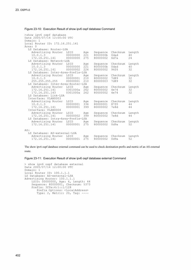
23. OSPFv3
Figure 23-10: Execution Result of show ipv6 ospf database Command
>show ipv6 ospf databaseDate 2005/07/14 12:00:00 UTCDomain: 1Local Router ID: 172.16.251.141Area: 0 LS Database: Router-LSA Advertising Router LSID Age Sequence Checksum Length 10.0.1.3 00000000 221 8000000b 0dad 40 172.16.251.141 00000000 275 80000002 6d7a 24 LS Database: Network-LSA Advertising Router LSID Age Sequence Checksum Length 10.0.1.3 00000000 221 8000000b 0dad 40 172.16.251.141 00000002 226 80000002 94f6 32 LS Database: Inter-Area-Prefix-LSA Advertising Router LSID Age Sequence Checksum Length 10.0.1.3 00000001 210 80000002 7d89 32 255.255.255.255 00000001 210 80000003 7d89 32 LS Database: Inter-Area-Router-LSA Advertising Router LSID Age Sequence Checksum Length 172.16.251.141 0301000a 262 80000002 4e74 32 172.16.251.143 0301000a 262 80000002 4e74 32 LS Database: Link-LSA Interface: VLAN0003 Advertising Router LSID Age Sequence Checksum Length 10.0.1.3 00000001 336 80000001 87f0 44 172.16.251.141 00000001 399 80000002 7e8d 44 Interface: VLAN0004 Advertising Router LSID Age Sequence Checksum Length 172.16.251.141 00000002 399 80000002 7e8d 44 LS Database: Intra-Area-Prefix-LSA Advertising Router LSID Age Sequence Checksum Length 172.16.251.141 00000001 275 80000002 0d9a 52 AS: LS Database: AS-external-LSA Advertising Router LSID Age Sequence Checksum Length 172.16.251.141 00000001 275 80000002 0d9a 52
The show ipv6 ospf database external command can be used to check destination prefix and metric of an AS external route.
Figure 23-11: Execution Result of show ipv6 ospf database external Command
> show ipv6 ospf database externalDate 2005/07/14 12:00:00 UTCDomain: 1Local Router ID: 100.1.1.1LS Database: AS-external-LSAAdvertising Router: 100.1.1.1 LSID: 00000000, Age: 6, Length: 44 Sequence: 80000001, Checksum: 5373 Prefix: 3ffe:4:1::1/128 Prefix Options: <LocalAddress> Type: 2, Metric: 20, Tag: ----
402
24. OSPFv3 Extended Function
24OSPFv3 Extended Function This chapter describes the OSPFv3 extended functions.
24.1 Area and Area Partitioning Function Overview
24.2 Configuration of Area
24.3 Graceful Restart Overview
24.4 Configuration of Graceful Restart
24.5 Stub Router Overview
24.6 Configuration of Stub Router
24.7 Operation of OSPFv3 Extended Function
403

24. OSPFv3 Extended Function
24.1 Area and Area Partitioning Function Overview
24.1.1 Area BorderIn OSPFv3, AS can be divided into multiple areas for the purpose of reducing the time that is required to process the algorithm used in the route selection.
An example is shown in the figure below of an OSPFv3 network topology using area partitioning.
Figure 24-1: Example of OSPFv3 Network Topology Using Area Partitioning
A router belonging to multiple areas like Router 2 or Router 5 is called an area border router.
The information on the connection state in an area is not notified to other areas. A router contains no information on the connection state in the area that is not connected.
(1) Backbone
The area where the area ID is 0.0.0.0 is called the backbone. The backbone plays a special part when AS is divided into multiple areas. When dividing AS into multiple areas, one of them must be set as a backbone area. However, do not configure so that two or more backbones exist in one AS. In such configuration, information is dispersed into each backbone. Therefore, an unreachable route may be generated or an optimum route may not be selected.
The area border router also reports the summarized path information of backbone and that of other areas flowing through the backbone to the routers in the connected areas other than backbone.
(2) Note on area partitioning
Area partitioning lessens the load on a router or path information traffic, but the OSPFv3 algorithm is more complicated. Especially, it becomes difficult to perform a proper operation when trouble occurs. Area partitioning should not be performed if there is no problem with the router or network load.
(3) Notes on area border router• An area border router operates the SPF algorithm proportionally to the number of areas to which it belongs. The area
border router has a function that summarizes the topology information in a certain area and reports it to other areas. Therefore, the area border router load increases when the number of areas to which the area border router belongs increases. It is thus recommended to construct a network so that the area border router does not belong to excessively many areas.
• When only one area border router exists in a certain area, the connectivity with other areas is lost by disconnecting the area border router from a backbone if a failure occurs in this area border router. Multiple area border routers should be arranged in the area which the server that offers an important function or the AS border router that has an
404
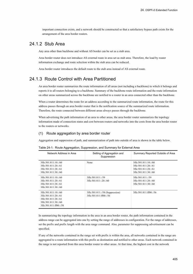
24. OSPFv3 Extended Function
important connection exists, and a network should be constructed so that a satisfactory bypass path exists for the arrangement of the area border routers.
24.1.2 Stub AreaAny area other than backbone and without AS border can be set as a stub area.
Area border router does not introduce AS external route in area set as stub area. Therefore, the load by router information exchange and route selection within the stub area can be reduced.
Area border router introduces the default route to the stub area instead of AS external route.
24.1.3 Route Control with Area PartitionedAn area border router summarizes the route information of all areas (not including a backbone) to which it belongs and reports it to all routers belonging to a backbone. Summary of the backbone route information and the route information on other areas summarized across the backbone are notified to a router in an area connected other than the backbone.
When a router determines the route for an address according to the summarized route information, the route for this address passes through an area border router that is the notification source of the summarized route information. Therefore, the route connected between different areas always passes through the backbone.
When advertising the path information of an area to other areas, the area border router summarizes the topology information made of connection states and cost between routers and networks into the costs from the area border router to the routers or networks.
(1) Route aggregation by area border router
Aggregation and suppression of path, and summarization of path into outside of area is shown in the table below.
Table 24-1: Route Aggregation, Suppression, and Summary for External Area
In summarizing the topology information in the area in an area border router, the path information contained in the address range can be aggregated into one by setting the range of addresses in configuration. For the range of addresses, set the prefix and prefix length with the area range command. Also, parameter for suppressing advertisement can be specified.
If any of the networks contained in the range set with prefix is within the area, all networks contained in the range are aggregated to a route information with this prefix as destination and notified to other areas. Each network contained in the range is not reported from this area border router to other areas. At that time, the highest cost in the network
Network Address in Area Setting of Aggregation and Suppression
Summary Reported Outside of Area
3ffe:501:811:10::/603ffe:501:811:20::/613ffe:501:811:28::/613ffe:501:811:30::/60
None 3ffe:501:811:10::/603ffe:501:811:20::/613ffe:501:811:28::/613ffe:501:811:30::/60
3ffe:501:811:10::/603ffe:501:811:20::/613ffe:501:811:28::/613ffe:501:811:30::/60
3ffe:501:811::/593ffe:501:811::20::/60
3ffe:501:811::/593ffe:501:811:20::/603ffe:501:811:30::/60
3ffe:501:811:10::/603ffe:501:811:20::/613ffe:501:811:28::/613ffe:501:811:30::/603ffe:501:811:ff00::/58
3ffe:501:811::/58 (Suppression)3ffe:501:811:ff00::/56
3ffe:501:811:ff00::/56
405

24. OSPFv3 Extended Function
contained in the range is used for the cost of the aggregated path information.
When advertising is suppressed, each network in the range is not notified to other areas. Moreover, the route aggregated into the prefix is also not notified to other areas. As a result, the path to the address contained in the specified range seems to be nonexistent when viewing from other areas through the area border router.
24.1.4 Virtual LinkIn OSPFv3, the two area border routers in an area that are not set as a stub area and are not the backbone can be used as the interface of the backbone by virtualizing the route between the two routers in this area as a point-to-point line. This virtual line is called a virtual link. The area in which the actual path of a virtual link exists is called the transit area of a virtual link.
The ways to use a virtual link is described below.
• Virtual connection of area not physically connected to backbone• Coupling of multiple backbones• Reserving path for the disconnection caused by backbone failure
(a) Virtual connection of area not physically connected to backbone
In the figure below, Area 2 is not connected to the backbone. In this case, Router 2 becomes an area border router connected to the backbone when a virtual link is set between Router 1 and Router 2 with area 1 used as a transit area. At that time, area 2 is considered to be connected to the backbone.
Figure 24-2: Connection of Areas to Backbone
(b) Coupling of multiple backbones
In the figure below, two backbone areas exist in AS. In this state, a failure in which the route cannot be reached due to the disruption of a backbone may occur. In this case, the backbone is linked when a virtual link that has area 1 as a transit area is set between routers 1 and 2. As a result, the failure can be avoided.
Figure 24-3: Connection between Backbones
(c) Reserving path for the disconnection caused by backbone failure
In the figure below, a backbone is disconnected when Router1 and Router2 are disconnected due to the network failure in a backbone. In this case, when a virtual link is set between Router 1 and Router 2 with area 1 used as a transit area, it becomes a reserved path for disconnection of a backbone (becomes a main path if the cost of a virtual link is sufficiently lower than that of Router 1 and Router 2 in a backbone).
406

24. OSPFv3 Extended Function
Figure 24-4: Reserved Path for Disconnection of Backbone
24.1.5 Virtual Link OperationA virtual link must be made to routers on both ends of the virtual link. Routers at both ends of a virtual link transmits OSPFv3 packets with neighboring routers using IPv6 global address or IPv6 site local address. The IPv6 address set on the interface belonging to the transit area is used for this address.
Note the following when operating the virtual link.
• An IPv6 global address or IPv6 site local address must be set for an arbitrary interface in a transit area. The virtual link to a neighboring router that advertises no IPv6 global address or IPv6 site local address does not operate.
• The cost of a virtual link corresponds to the cost of the path between routers on both ends of the virtual link in a transit area.
• In a transit area, the path for general traffic may differ from the path information traffic in the virtual link when the path between routers on both ends of a virtual link is an equal cost multipath.
(1) Connection with neighboring router
While the virtual link is up, Hello packets are sent to the neighboring routers on the virtual link in order to detect connectivity between routers. The virtual link is up when the path to the other side router in a virtual link exists in the transit area.
It is recognized that OSPFv3 operates between routers by receiving Hello packets from other routers.
Configuration related to Hello packets is set by area virtual-link command. The dead-interval must be longer than any interval (set with ipv6 ospf dead-interval command) of the interface on each network forming the route between the end routers of a virtual link on the transit area. If this value is set shorter than any of them, the virtual link may be interrupted before the routes used by virtual links are shifted based on the shift to alternate routes within the transit area when a malfunction occurs in the routes within the transit area.
Retransmission interval (retransmit-interval parameter of area virtual-link command) of LSA must be set sufficiently longer than the time required for the packet to pass back and forth between the routers at each end of virtual link.
407

24. OSPFv3 Extended Function
24.2 Configuration of Area
24.2.1 List of Configuration CommandsA list of configuration commands when using stub area and when operating as area border router are shown.
Refer to "Table 23-5: List of Configuration Commands Related to AS External Route", "Table 23-6: List of Configuration Commands Related to Route Selection and Route Learning", and "Table 23-7: List of Configuration Commands" for the commands of functions described in "23 OSPFv3".
Table 24-2: List of Area Related Configuration Commands
Table 24-3: List of Configuration Commands Related to OSPFv3 Application
24.2.2 Flow of Configuring
(1) Procedure for setting stub area when not an area border
1. First, configure the IPv6 resources with the swrt_table_resource command.This is necessary in order to perform IPv6 routing.
2. Configure the IPv6 interface in advance.
3. Set stub area.
4. Configure to use OSPFv3.
(2) Procedure for setting area border router
1. First, configure the IPv6 resources with the swrt_table_resource command.This is necessary in order to perform IPv6 routing.
2. Configure the IPv6 interface in advance.
3. Set the area operating as stub area.
4. Make settings for aggregation of route.
5. Configure to use OSPFv3.Set multiple areas. At this time, settings of interface belonging to area 0 (backbone) or settings of virtual link must be made.
6. Set the virtual link.
Command Description
area default-cost Sets the cost value of the default route to be advertised to the stub area.
area range Aggregates and advertises the route between areas to a specified prefix with the area border router.
area stub Operates as stub area.
area virtual-link Sets the virtual link.
Command Description
disable Suppresses OSPFv3 operation.
ipv6 ospf area Sets the OSPFv3 domain number and area ID.
router-id Sets router ID (identifier of the router).
408

24. OSPFv3 Extended Function
24.2.3 Setting Stub Area[Point of setting]
Area border router advertises the default route into the area for which area stub command is set.Stub area configuration must be performed for all routers within the same area.
[Setup using commands]
1. (config)# ipv6 router ospf 1
Enters ospfv3 mode. Sets the domain number to 1.
2. (config-rtr)# area 1 stub
Sets area 1 to stub area.
3. (config-rtr)# router-id 100.1.1.1
(config-rtr)# exit
Uses 100.1.1.1 as router ID.
4. (config)# interface vlan 2
(config-if)# ipv6 ospf 1 area 1
Specifies to operate in area 1 of domain 1.
24.2.4 Setting Area Border Router[Point of setting]
By specifying the not-advertise parameter, the area range command can suppress advertising outside the area of network contained in the range of this prefix.The aggregated and suppressed address range can be set one or more for each area. Moreover, a router or network that uses the address not contained in any setting range can exist in an area. However, assign the address corresponding to topology and use the range corresponding to topology to set aggregation when configuring a network. This enables the route information traffic of OSPFv3 to be efficiently reduced without damaging the appropriateness of the route to be selected.An example of configuring route aggregation for area border router belonging to Area 0 and Area 1 is shown.
[Setup using commands]
1. (config)# ipv6 router ospf 1
(config-rtr)# area 0 range 3ffe:501:811::/59
When a route within the range of prefix 3ffe:501:811::/59 is learned in Area 0, an aggregate route is advertised to Area 1.
2. (config-rtr)# area 1 range 3ffe:501:811::20::/60
(config-rtr)# exit
When a route within the range of prefix 3ffe:501:811::20::/60 is learned in Area 1, an aggregate route is advertised to Area 0.
3. (config)# interface vlan 3
(config-if)# ipv6 ospf 1 area 0
(config-if)# exit
(config)# interface vlan 1
(config-if)# ipv6 ospf 1 area 1
409

24. OSPFv3 Extended Function
By configuring an interface applying OSPFv3, it becomes the area border between Area 0 and Area 1.
24.2.5 Setting Virtual Link[Point of setting]
Set the router ID of the remote router by area virtual-link command.
[Setup using commands]
1. (config)# interface vlan 1
(config-if)# ipv6 ospf 1 area 1
(config-if)# exit
Applies OSPFv3.
2. (config)# ipv6 router ospf 1
(config-rtr)# area 1 virtual-link 10.0.0.1
(config-rtr)# area 1 virtual-link 10.0.0.2
Sets the remote router in transit area 1.
410

24. OSPFv3 Extended Function
24.3 Graceful Restart Overview
24.3.1 Outline of Graceful RestartIn OSPFv3, the system that restarts the OSPFv3 by graceful restart is called the restart router. The graceful restart function of the restart router is called the restart function. The neighboring system that assists graceful restart is called the helper router. The graceful restart function of the helper router is called the helper function.
The LANSW module supports the helper function.
24.3.2 Helper FunctionWhen the LANSW module is operating as a helper router, the route passing through the restart router is maintained while graceful restart is in progress.
(1) Helper function operating condition
The helper function operating conditions are as follows:
• The router is not already a helper of another restart router within the same domain.A router cannot function as a helper router for graceful restart of more than one router within the same domain. However, if there is only one restart router, it functions as helper router on all interfaces connected to that restart router.
• The local router is not performing graceful restart as a restart router.• Not waiting for an Ack of OSPFv3 Update packet sent to a restart router.
(2) Case when helper function fails
Operation as a helper router continues until neighbor is established or completion notice is received from the restart router.
However, if any of the following events occur, the helper function is interrupted and the route is recalculated because there may be a conflict with the route maintained by the restart router.
• A new LSA is learned from the neighboring router (excluding periodic update) and is advertised to the restart router.• The OSPFv3 interface goes down.• LSA is updated by disconnection or establishment of neighbor adjacency with router other than the restart router.• Multiple routers are restarted simultaneously within the same OSPFv3 domain.• When the configuration is deleted and helper function is deleted with the graceful-restart mode command.
411

24. OSPFv3 Extended Function
24.4 Configuration of Graceful Restart
24.4.1 List of Configuration CommandsWhen using the OSPFv3 restart function on the OSPFv3 neighboring router of the LANSW module, configure the OSPFv3 helper function on the LANSW module.
The graceful restart configuration command list is shown in the table below.
Table 24-4: List of Configuration Commands
24.4.2 Helper Function[Point of setting]
Specify the helper function to be used. If omitted, the router does not operate.
[Setup using commands]
1. (config)# ipv6 router ospf 1
(config-rtr)# graceful-restart mode helper
Enables helper function.
Command Description
graceful-restart mode Activates the helper function.
graceful-restart strict-lsa-checking Stops graceful restart if the LSA databases are not synchronized between the helper router and restart router.
412

24. OSPFv3 Extended Function
24.5 Stub Router Overview
24.5.1 Outline of Stub RouterIf connection with the neighboring router is not completed or stabilized, routing of the entire network may become instable. When the router is being started or restarted or a router is being added to the network, such a situation may arise. Under such circumstances, OSPFv3 can notify the route information in such a way that surrounding systems will use the information for routing as less as possible. In OSPFv3, the router making such a notification is called the stub router. Using this function, you can prevent network routing from becoming instable even though the system status is instable.
(1) Max metric
The stub router advertises the cost value of the connected OSPFv3 interface as the maximum value (65535). Therefore, the OSPFv3 route that passes through the stub router does not take precedence.
However, for the route of the interface for which no neighboring router exists (stub network), the cost value specified using the configuration command is advertised. The route advertised by the stub router may take precedence over the stub network or AS external route.
Surrounding systems compare the metrics and prefer the alternative route that does not pass through the stub router. Using the system address of the stub router itself, management via telnet or route exchange via BGP4+ is allowed.
24.5.2 Stub Router OperationConfiguration command max-metric router-lsa specifies whether the stub router function runs for each domain. Further, whether the stub router always runs or runs after the start can be selected as the operation condition.
(1) If the stub router always runs
The cost is always set to the maximum value. The stub router keeps on running until the stub router configuration is deleted.
(2) If the stub router runs after the start
In the timing below, the cost is set to the maximum value. The stub router keeps on running until the deadline specified in the configuration elapses.
• After restart of the routing program• System start
The stub router can be stopped by executing operation command clear ipv6 ospf stub-router during operation or deleting the configuration. The stub router operation is shown in the figure below.
413

24. OSPFv3 Extended Function
Figure 24-5: Stub Router Operation
(3) Notes
1. When the stub router is running as the helper router for graceful restart, do not change the stub router configuration. If the configuration is changed, the stub router may start or stop running and the helper action may fail.
2. If the stub router that is set to always run is changed to run after the start, the stub router is immediately ended.3. The virtual link that passes through the sub router is not available.
If the cost in the passage area is higher than 65535, the virtual neighbor assumes that the virtual link is unreachable.
414

24. OSPFv3 Extended Function
24.6 Configuration of Stub Router
24.6.1 List of Configuration CommandsIf you do not prefer the route that passes through the LANSW module, set the stub router. The metric of the route that passes through the stub router can be increased.
The following table lists the stub router configuration commands:
Table 24-5: List of Configuration Commands
24.6.2 Stub Router Function[Point of setting]
Specify the stub router operation. If the on-startup parameter is not specified, the stub router always runs.
[Setup using commands]
1. (config)# ipv6 router ospf 1
(config-rtr)# max-metric router-lsa
Uses the stub router function.
Command Description
max-metric router-lsa Runs as the stub router.
415

24. OSPFv3 Extended Function
24.7 Operation of OSPFv3 Extended Function
24.7.1 List of Operation CommandsThe following table provides a list of OSPFv3 extended function operation commands.
Table 24-6: List of Operation Commands
24.7.2 Checking Area BorderAt the area border, use the show ipv6 ospf command to check that the router type (Flags) contain "AreaBorder".
Also, check that route aggregation between areas is reflected correctly.
Figure 24-6: Execution Result of show ipv6 ospf Command
>show ipv6 ospfDate 2005/07/14 12:00:00 UTCOSPFv3 protocol: ON Domain: 1Router ID: 172.16.1.1Distance:Intra Area: 10, Inter Area: 10, External: 150Flags: <AreaBorder ASBoundary>SPF Interval: 7s, SPF Delay: 3sGraceful Restart: Helper Helper Status : Finished 2005/07/08 14:12:22Area: 0, Interfaces: 2 Network Range State 3ffe:501:ffff:100::/64 DoNotAdvertise 3ffe:501:ffff:200::/64 AdvertiseArea: 1, Interfaces: 1 Network Range State - -
24.7.3 Checking AreaCheck that the configured areas is reflected correctly. A list of areas is displayed when the area parameter of the show ipv6 ospf command is specified.
Figure 24-7: Execution Result of show ipv6 ospf Command (area Parameter)
>show ipv6 ospf areaDate 2005/07/14 12:00:00 UTCDomain: 1Area ID Neighbor SPFcount Flags0 3 14 <ASBoundary>10 2 8 <Stub>>
24.7.4 Checking Graceful RestartUse the show ipv6 ospf command to check the graceful restart state.
Command Description
show ipv6 ospf Displays domain information (area border state, graceful restart state, etc.) or area.
clear ipv6 ospf stub-router Stops the stub router operation.
416

24. OSPFv3 Extended Function
Figure 24-8: Execution Result of show ipv6 ospf Command
>show ipv6 ospfDate 2005/07/14 12:00:00 UTCOSPFv3 protocol: ON Domain: 1Router ID: 172.16.1.1Distance:Intra Area: 10, Inter Area: 10, External: 150Flags: <AreaBorder ASBoundary>SPF Interval: 7s, SPF Delay: 3sGraceful Restart: Helper Helper Status : Finished 2005/07/08 14:12:22Area: 0, Interfaces: 2 Network Range State 3ffe:501:ffff:100::/64 DoNotAdvertiseArea: 1, Interfaces: 1 Network Range State - -
417

24. OSPFv3 Extended Function
418

25. BGP4+
25BGP4+ This chapter explains the BGP4+ specifications and discusses the notes that should be taken using it.
25.1 Basic Function Overview
25.2 Configuration of Basic Functions
25.3 Operation of Basic Function
25.4 Extended Function Overview
25.5 Configuration of Extended Function
25.6 Operation of Extended Function
419

25. BGP4+
25.1 Basic Function Overview
25.1.1 Outline of BGP4+BGP4+ (Multiprotocol Extensions for Border Gateway Protocol 4) is the protocol extended so that routing protocol BGP4 used as an Internet backbone can also be used for protocols other than IPv4. BGP4+ can handle all route information used in the Internet.
Function difference between BGP4+ (IPv6) and BGP4 (IPv4) are described below.
Table 25-1: Functional Difference between BGP4+ (IPv6) and BGP4 (IPv4)
(Legend) Y: Handled N: Not handled*1 Grouping of external peers and member AS peers or internal peers*2 Only receive router function is supported.
25.1.2 Peer Type and Connection ModeBGP4+ is the primary routing protocol used in the Internet for communications between Autonomous Systems (AS). Route information is composed of AS path information to destination networks (AS path that the packet passes to reach the destination network). The router where BGP4+ operates is called a BGP4+ speaker. This BGP4+ speaker forms a peer to exchange route information with other BGP4+ speakers.
The type of peers used by the LANSW module is external peer and internal peer. In the confederation configuration, the member AS peer is added apart from these two types of peers. For information on the member AS peer, see "25.4.10 Confederation".
Use the appropriate peer type matching the network configuration. The following figure shows the external peer and internal peer.
Function BGP4+ (IPv6) BGP4 (IPv4)
EBGP and IBGP peering, and route distribution Y Y
Route filter and BGP attribute change Y Y
Community Y Y
Route reflection Y Y
Confederation Y Y
Negotiation of supported function Y Y
Route refresh Y Y
Multipath Y Y
Peer group*1 Y Y
Route flap dampening Y Y
BGP4 MIB N Y
TCP MD5 authentication Y Y
Graceful restart Y*2 Y*2
Restriction on the number of learned routes Y Y
420
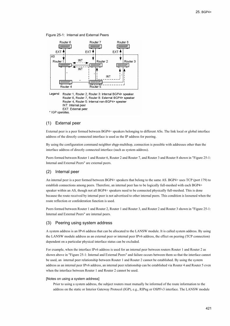
25. BGP4+
Figure 25-1: Internal and External Peers
(1) External peer
External peer is a peer formed between BGP4+ speakers belonging to different ASs. The link local or global interface address of the directly connected interface is used as the IP address for peering.
By using the configuration command neighbor ebgp-multihop, connection is possible with addresses other than the interface address of directly connected interface (such as system address).
Peers formed between Router 1 and Router 6, Router 2 and Router 7, and Router 3 and Router 8 shown in "Figure 25-1: Internal and External Peers" are external peers.
(2) Internal peer
An internal peer is a peer formed between BGP4+ speakers that belong to the same AS. BGP4+ uses TCP (port 179) to establish connections among peers. Therefore, an internal peer has to be logically full-meshed with each BGP4+ speaker within an AS, though not all BGP4+ speakers need to be connected physically full-meshed. This is done because the route received by internal peer is not advertised to other internal peers. This condition is loosened when the route reflection or confederation function is used.
Peers formed between Router 1 and Router 2, Router 1 and Router 3, and Router 2 and Router 3 shown in "Figure 25-1: Internal and External Peers" are internal peers.
(3) Peering using system address
A system address is an IPv6 address that can be allocated to the LANSW module. It is called system address. By using the LANSW module address as an external peer or internal peer IPv6 address, the effect on peering (TCP connection) dependent on a particular physical interface status can be excluded.
For example, when the interface IPv6 address is used for an internal peer between routers Router 1 and Router 2 as shown above in "Figure 25-1: Internal and External Peers" and failure occurs between them so that the interface cannot be used, an internal peer relationship between Router 1 and Router 2 cannot be established. By using the system address as an internal peer IPv6 address, an internal peer relationship can be established via Router 4 and Router 5 even when the interface between Router 1 and Router 2 cannot be used.
[Notes on using a system address]Prior to using a system address, the subject routers must mutually be informed of the route information to the address on the static or Interior Gateway Protocol (IGP), e.g., RIPng or OSPFv3 interface. The LANSW module
421
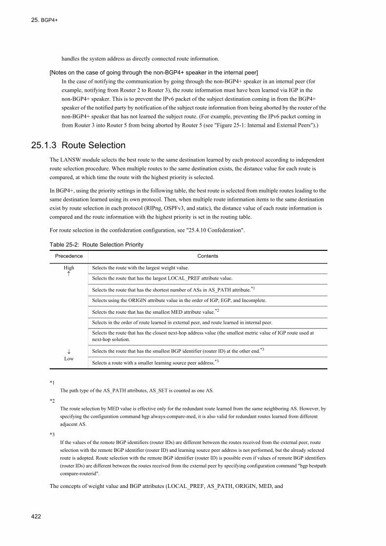
25. BGP4+
handles the system address as directly connected route information.
[Notes on the case of going through the non-BGP4+ speaker in the internal peer]In the case of notifying the communication by going through the non-BGP4+ speaker in an internal peer (for example, notifying from Router 2 to Router 3), the route information must have been learned via IGP in the non-BGP4+ speaker. This is to prevent the IPv6 packet of the subject destination coming in from the BGP4+ speaker of the notified party by notification of the subject route information from being aborted by the router of the non-BGP4+ speaker that has not learned the subject route. (For example, preventing the IPv6 packet coming in from Router 3 into Router 5 from being aborted by Router 5 (see "Figure 25-1: Internal and External Peers").)
25.1.3 Route SelectionThe LANSW module selects the best route to the same destination learned by each protocol according to independent route selection procedure. When multiple routes to the same destination exists, the distance value for each route is compared, at which time the route with the highest priority is selected.
In BGP4+, using the priority settings in the following table, the best route is selected from multiple routes leading to the same destination learned using its own protocol. Then, when multiple route information items to the same destination exist by route selection in each protocol (RIPng, OSPFv3, and static), the distance value of each route information is compared and the route information with the highest priority is set in the routing table.
For route selection in the confederation configuration, see "25.4.10 Confederation".
Table 25-2: Route Selection Priority
*1The path type of the AS_PATH attributes, AS_SET is counted as one AS.
*2The route selection by MED value is effective only for the redundant route learned from the same neighboring AS. However, by specifying the configuration command bgp always-compare-med, it is also valid for redundant routes learned from different adjacent AS.
*3If the values of the remote BGP identifiers (router IDs) are different between the routes received from the external peer, route selection with the remote BGP identifier (router ID) and learning source peer address is not performed, but the already selected route is adopted. Route selection with the remote BGP identifier (router ID) is possible even if values of remote BGP identifiers (router IDs) are different between the routes received from the external peer by specifying configuration command "bgp bestpath compare-routerid".
The concepts of weight value and BGP attributes (LOCAL_PREF, AS_PATH, ORIGIN, MED, and
Precedence Contents
High↑
↓Low
Selects the route with the largest weight value.
Selects the route that has the largest LOCAL_PREF attribute value.
Selects the route that has the shortest number of ASs in AS_PATH attribute.*1
Selects using the ORIGIN attribute value in the order of IGP, EGP, and Incomplete.
Selects the route that has the smallest MED attribute value.*2
Selects in the order of route learned in external peer, and route learned in internal peer.
Selects the route that has the closest next-hop address value (the smallest metric value of IGP route used at next-hop solution.
Selects the route that has the smallest BGP identifier (router ID) at the other end.*3
Selects a route with a smaller learning source peer address.*3
422
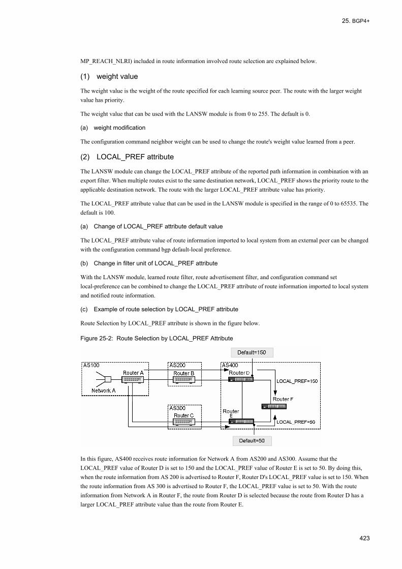
25. BGP4+
MP_REACH_NLRI) included in route information involved route selection are explained below.
(1) weight value
The weight value is the weight of the route specified for each learning source peer. The route with the larger weight value has priority.
The weight value that can be used with the LANSW module is from 0 to 255. The default is 0.
(a) weight modification
The configuration command neighbor weight can be used to change the route's weight value learned from a peer.
(2) LOCAL_PREF attribute
The LANSW module can change the LOCAL_PREF attribute of the reported path information in combination with an export filter. When multiple routes exist to the same destination network, LOCAL_PREF shows the priority route to the applicable destination network. The route with the larger LOCAL_PREF attribute value has priority.
The LOCAL_PREF attribute value that can be used in the LANSW module is specified in the range of 0 to 65535. The default is 100.
(a) Change of LOCAL_PREF attribute default value
The LOCAL_PREF attribute value of route information imported to local system from an external peer can be changed with the configuration command bgp default-local preference.
(b) Change in filter unit of LOCAL_PREF attribute
With the LANSW module, learned route filter, route advertisement filter, and configuration command set local-preference can be combined to change the LOCAL_PREF attribute of route information imported to local system and notified route information.
(c) Example of route selection by LOCAL_PREF attribute
Route Selection by LOCAL_PREF attribute is shown in the figure below.
Figure 25-2: Route Selection by LOCAL_PREF Attribute
In this figure, AS400 receives route information for Network A from AS200 and AS300. Assume that the LOCAL_PREF value of Router D is set to 150 and the LOCAL_PREF value of Router E is set to 50. By doing this, when the route information from AS 200 is advertised to Router F, Router D's LOCAL_PREF value is set to 150. When the route information from AS 300 is advertised to Router F, the LOCAL_PREF value is set to 50. With the route information from Network A in Router F, the route from Router D is selected because the route from Router D has a larger LOCAL_PREF attribute value than the route from Router E.
423
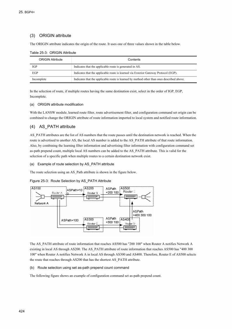
25. BGP4+
(3) ORIGIN attribute
The ORIGIN attribute indicates the origin of the route. It uses one of three values shown in the table below.
Table 25-3: ORIGIN Attribute
In the selection of route, if multiple routes having the same destination exist, select in the order of IGP, EGP, Incomplete.
(a) ORIGIN attribute modification
With the LANSW module, learned route filter, route advertisement filter, and configuration command set origin can be combined to change the ORIGIN attribute of route information imported to local system and notified route information.
(4) AS_PATH attribute
AS_PATH attributes are the list of AS numbers that the route passes until the destination network is reached. When the route is advertised to another AS, the local AS number is added to the AS_PATH attribute of that route information. Also, by combining the learning filter information and advertising filter information with configuration command set as-path prepend count, multiple local AS numbers can be added to the AS_PATH attribute. This is valid for the selection of a specific path when multiple routes to a certain destination network exist.
(a) Example of route selection by AS_PATH attribute
The route selection using an AS_Path attribute is shown in the figure below.
Figure 25-3: Route Selection by AS_PATH Attribute
The AS_PATH attribute of route information that reaches AS500 has "200 100" when Router A notifies Network A existing in local AS through AS200. The AS_PATH attribute of route information that reaches AS500 has "400 300 100" when Router A notifies Network A in local AS through AS300 and AS400. Therefore, Router E of AS500 selects the route that reaches through AS200 that has the shortest AS_PATH attribute.
(b) Route selection using set as-path prepend count command
The following figure shows an example of configuration command set as-path prepend count.
ORIGIN Attribute Contents
IGP Indicates that the applicable route is generated in AS.
EGP Indicates that the applicable route is learned via Exterior Gateway Protocol (EGP).
Incomplete Indicates that the applicable route is learned by method other than ones described above.
424

25. BGP4+
Figure 25-4: Example of Using set as-path prepend count Command
In this figure, multiple local AS numbers are added to the AS_PATH attribute of the route information notified to AS200 when Router A requests Router E to select a route through AS300 and AS400. For example, the AS_PATH attribute of route information that reaches AS500 through AS200 has "200 100 100 100" when three local AS numbers are added. Router E selects a route that reaches through AS300 and AS400 that have the shortest AS_PATH attribute.
(5) MED attribute
The MED attribute determines the priority of BGP4+ routes to a given destination learned from the same neighboring AS's. The path information that is lower in a MED attribute value has priority. It can be used to select the priority between BGP4+ routes learned from different neighboring AS's by specifying the configuration command bgp always-compare-med.
(a) Example of route selection using MED attribute
An example of the route selection by MED attribute is shown in the figure below.
Figure 25-5: Example of Route Selection by MED Attribute
Router C advertises the route for a particular destination network to Router A with a MED attribute value of 10. Router D advertises the route for the same destination network to Router A with a MED attribute value of 20. In this case, Router A selects the route with the smaller MED value of 10 advertised by Router C as the route to the destination network.
(b) MED attribute modification
With the LANSW module, learning filter, advertising filter, and configuration command set metric can be combined to change the MED attribute of route information imported to local system and notified route information.
The metric value of an IGP route used for NextHop resolution can be changed to the MED attribute value of the BGP4+ route to be notified when internal is specified for set metric-type. An example using set metric-type internal is shown in the figure below.
425

25. BGP4+
Figure 25-6: Example of Using set metric-type internal
This figure shows an internal peer formed between Router A and B. Specify the configuration command set-metric on Router B in order to set the MED attribute to metric value = 2 of the IGP route between Router B and A when Router B notifies Router C of the BGP4+ route information that was transmitted from Router A with MED attribute value = 100.
(6) Next hop information of MP_REACH_NLRI attribute
In BGP4+, the value of the NextHop attribute received from a BGP4+ peer is ignored. Instead, the next hop information of an MP_REACH_NLRL attribute is used as the next hop of a path.
When notifying the route information to the remote BGP+4 speaker in BGP4+, the global address and link local address (for an external peer only) of the source interface used for peering are set only if peering is made using IPv6 global address as the next hop information of MP_REACH_NLRI attribute.
(a) Example of setting next hop
An example of setting next hop of notified route information is shown in the figure below.
Figure 25-7: Setting Example of Route Information Next Hop to Be Notified
• Path information to Router B that forms an external peerThe global and link local addresses (Ib) on Router A side of the interface between Router A and Router B are allocated to the next hop information of an MP_REACH_NLRI attribute. Router A is not related with whether Router B uses the global address or link local address as the actual next hop information.
• Path information from Router B that forms a direct-connected external peerIf only a global address or link local address is contained in the next hop information of an MP_REACH_NLRI attribute, the address is used as next hop information. If both addresses are contained, the link local address is used as next hop information.
• Route information to Router C that forms an internal peerThe global address set in the next hop of the MP_REACH_NLRI attribute of the route information received from Router B is set in the next hop of the MP_REACH_NLRI attribute.If the global address of the next hop of the MP_REACH_NLRI attribute of the route information received from Router B is not set, the global address on the LANSW module side of the interface between Router A and Router C is set.
• Route information to Router D that forms an internal peer
426

25. BGP4+
The global address set in the next hop of the MP_REACH_NLRI attribute of the route information received from Router B is set in the next hop of the MP_REACH_NLRI attribute.If the global address of the next hop of the MP_REACH_NLRI attribute of the route information received from Router B is not set, the global address on the LANSW module side of the interface between Router A and Router D is set.
(b) When rewriting next hop
On the LANSW module, when only global address is set in next hop of MP_REACH_NLRI attribute of the route information received from external peer or the peer between member ASs, the configuration command neighbor next-hop-self can be used to rewrite the next hop of MP_REACH_NLRI attribute when advertising route information received from external peer or the peer between member ASs to internal peer with local side address used for peering. By configuration command "neighbor always-nexthop-self", you can set to overwrite the NEXT_HOP attribute for advertisement to internal peers including route reflection with the local address used for peering. Also by configuration command "neighbor set-nexthop-peer", you can set to overwrite the NEXT_HOP attribute of learned route with the address of the peer router.
(c) Nexthop resolution
When BGP4+ route information is learned from internal peer, the path to reach the address indicated by the next hop information of the MP_REACH_NLRI attribute is resolved by IGP route, static route, direct connection route, and BGP4+ route. The route with the longest destination mask is selected among the routes reachable to the next hop of the BGP4+ route and the path of the corresponding route is used as the path of the BGP4+ route.
Using configuration command "bgp nexthop", the protocol type and prefix of the route to be used for Next Hop resolution can be specified.
If the route with NextHop resolved is a static route and noninstall parameter is specified, the corresponding BGP4+ route is suppressed.
25.1.4 Notes on Using BGP4+Note the following limitation items when configuring a network using BGP4+.
(1) Limitation on BGP4+
The LANSW module conforms to RFC1771 (BGP version 4 specifications), RFC1997 (community specifications), RFC2842 (advertisement specifications of a support function), and RFC2918 (route refresh specifications), RFC2796 (route reflection specification) and RFC1965 (confederation specification), but deviates from some RFCs due to software limitations. The deviation from RFC is shown in the table below. The LANSW module supports only BGP version 4.
427

25. BGP4+
Table 25-4: Deviations from RFC
RFC No. RFC The LANSW module
RFC1771 Message header format
When message type is OPEN and has an authentication tag, the marker value can be predicted by calculation via the authentication mechanism.
Authentication function is not supported.
Path attribute: NEXT_HOP
When a BGP speaker advertises the route to another BGP speaker within the same AS, the NEXT_HOP attribute related to the route must not be modified.
In BGP4+, a NEXT HOP attribute is only a dummy parameter.
Path attribute: ATOMIC_AGGREGATE
With a BGP speaker, if one of the peers advertises an aggregate route and a less specific route instead of more specific route is selected, the system must add an ATOMIC_AGGREGATE attribute to the route information when reporting it to other BGP speakers.
With the LANSW module, when an aggregate route is received from one of the peers and only more specific route setting is installed, the router reports to other BGP speakers the route information without adding ATOMIC_AGGREGATE attribute.
Detection of connection collision
The local system must check all connections in OpenConfirm status when receiving the OPEN message. If possible to identify the peer BGP identifier by any means other than protocol, it must check connections in OpenSent status as well.
Checks all connections in OpenSent or Connect status when receiving the OPEN message.
Version negotiation
A BGP speaker can determine the subject protocol version by starting with the highest version supported and trying to open BGP connection multiple times.
The LANSW module only supports BGP4+ (version 4).
BGP FSM: Idle status
When a peer enters an Idle status because of an error, the time until the following Start (if the Start event is automatically generated) must increase exponentially. The first timer value is 60 seconds. Time must be doubled for each retry.
The first timer between Idle status and start is 16 to 36 seconds.
BGP FSM: Active status
When the transport protocol connection has been successful, a local system clears the Connect Retry timer, completes the initial setup, sends an OPEN message to that peer, sets the Hold timer, and changes the status to Open Sent. Four minutes is suggested for the Hold timer value.
The default Hold timer is 180 seconds (3 minutes) which can be changed with configuration.
Frequency of route advertisement
Min Route Advertisement Interval determines the minimum interval of time for the route advertisement from a single BGP speaker to a particular destination. The route restriction is processed for each destination. However, the value of Min Route Advertisement Interval is set on each BGP peer.
The LANSW module does not support Min Route Advertisement Interval.
Min AS Origination Interval determines the minimum interval of time between successive advertisement of UPDATE messages that report changes within the advertising BGP speaker's own AS.
The LANSW module does not support Min AS Origination Interval.
Jitter Jitter should be applied to timers related to Min AS Origination Interval, Keep Alive, and Min Route Advertisement Interval to minimize the possibility that BGP message advertised by a particular BGP speaker will contain peaks.
Jitter is not applied.
BGP timer Suggested value of Connect Retry timer is 120 seconds. The LANSW module varies the Connect Retry timer value (16 - 148 seconds) according to the Connect Retry frequency.
Suggested value of Hold Time is 90 seconds. Hold Time is set to 180 seconds by default. If the Hold Time is set by configuration, that value is used.
Suggested value of Keep Alive timer is 30 seconds. The default Keep Alive timer is 1/3 of Hold Timer. If the Keep Alive Time is set by configuration, that value is used.
428

25. BGP4+
(2) Notes on peering on a directly connected interface
Peer connection will not be established when the LANSW module uses an external peer or member AS peer between BGP speakers on a directly connected interface and the LANSW module is a transit area of an OSPFv3 virtual link on the same interface. In this case, setting a configuration command neighbor ebgp-multihop will establish the connection.
RFC2545 A link local address is also reported only when the reported next hop and the peer at the report destination exist in the same network.
In the LANSW module, the processing on the left is done only when an external peer is connected using a direct-coupled network.
Transport protocol
The TCP connection used for a BGP4+ session is IPv4 or IPv6.
The LANSW module supports only the report of IPv6 path information by IPv6 TCP.
Peering address type
An IPv4 or IPv6 address is used for BGP4+ peering. The LANSW module supports only an IPv6 address. For internal peer, the BGP4+ connection in an IPv6 link local address is not supported.
RFC1965 When advertising the route information to the member AS peer, adds the local member AS number in the type AS_CONFED_SEQUENCE to the AS_PATH attribute.
Adds the local member AS number in the type AS_CONFED_SET to the AS_PATH attribute.
RFC No. RFC The LANSW module
429
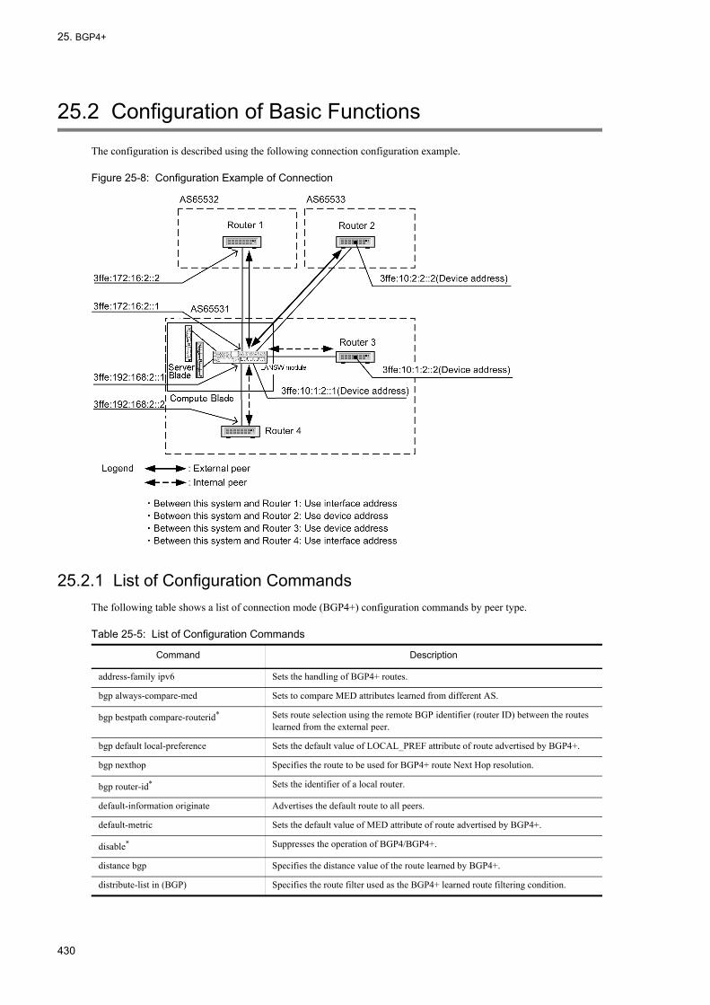
25. BGP4+
25.2 Configuration of Basic Functions
The configuration is described using the following connection configuration example.
Figure 25-8: Configuration Example of Connection
25.2.1 List of Configuration CommandsThe following table shows a list of connection mode (BGP4+) configuration commands by peer type.
Table 25-5: List of Configuration Commands
Command Description
address-family ipv6 Sets the handling of BGP4+ routes.
bgp always-compare-med Sets to compare MED attributes learned from different AS.
bgp bestpath compare-routerid* Sets route selection using the remote BGP identifier (router ID) between the routes learned from the external peer.
bgp default local-preference Sets the default value of LOCAL_PREF attribute of route advertised by BGP4+.
bgp nexthop Specifies the route to be used for BGP4+ route Next Hop resolution.
bgp router-id* Sets the identifier of a local router.
default-information originate Advertises the default route to all peers.
default-metric Sets the default value of MED attribute of route advertised by BGP4+.
disable* Suppresses the operation of BGP4/BGP4+.
distance bgp Specifies the distance value of the route learned by BGP4+.
distribute-list in (BGP) Specifies the route filter used as the BGP4+ learned route filtering condition.
430
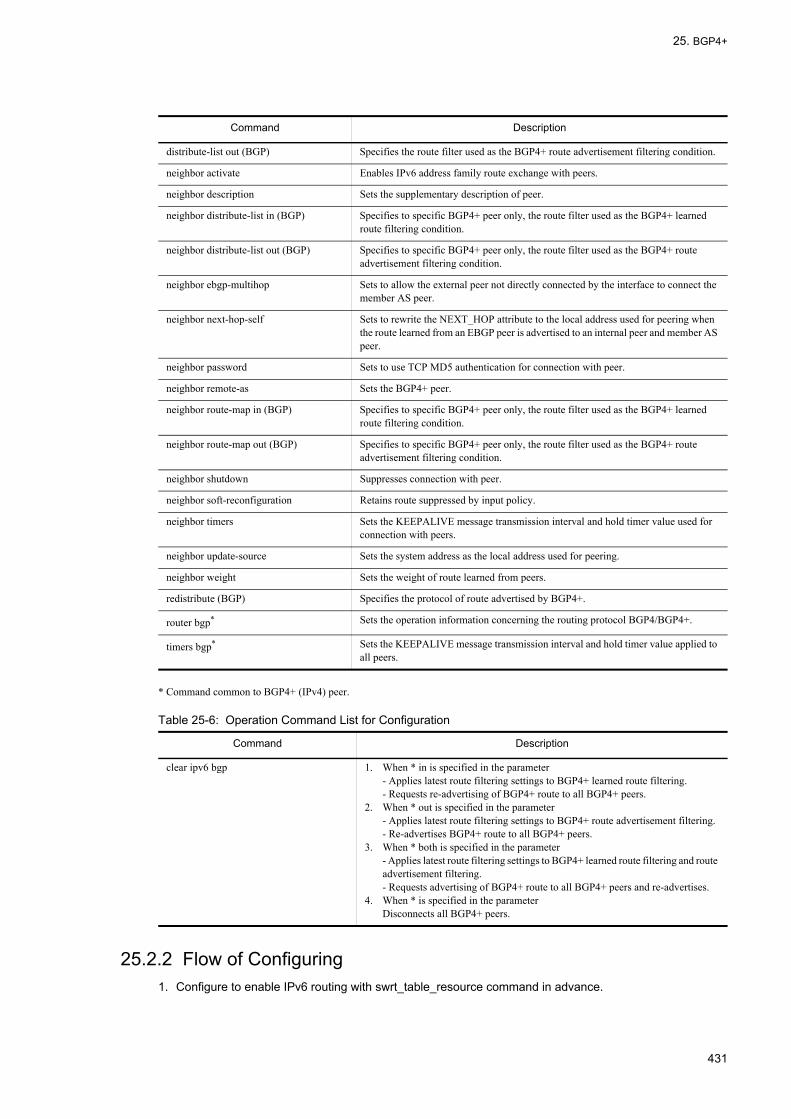
25. BGP4+
* Command common to BGP4+ (IPv4) peer.
Table 25-6: Operation Command List for Configuration
25.2.2 Flow of Configuring1. Configure to enable IPv6 routing with swrt_table_resource command in advance.
distribute-list out (BGP) Specifies the route filter used as the BGP4+ route advertisement filtering condition.
neighbor activate Enables IPv6 address family route exchange with peers.
neighbor description Sets the supplementary description of peer.
neighbor distribute-list in (BGP) Specifies to specific BGP4+ peer only, the route filter used as the BGP4+ learned route filtering condition.
neighbor distribute-list out (BGP) Specifies to specific BGP4+ peer only, the route filter used as the BGP4+ route advertisement filtering condition.
neighbor ebgp-multihop Sets to allow the external peer not directly connected by the interface to connect the member AS peer.
neighbor next-hop-self Sets to rewrite the NEXT_HOP attribute to the local address used for peering when the route learned from an EBGP peer is advertised to an internal peer and member AS peer.
neighbor password Sets to use TCP MD5 authentication for connection with peer.
neighbor remote-as Sets the BGP4+ peer.
neighbor route-map in (BGP) Specifies to specific BGP4+ peer only, the route filter used as the BGP4+ learned route filtering condition.
neighbor route-map out (BGP) Specifies to specific BGP4+ peer only, the route filter used as the BGP4+ route advertisement filtering condition.
neighbor shutdown Suppresses connection with peer.
neighbor soft-reconfiguration Retains route suppressed by input policy.
neighbor timers Sets the KEEPALIVE message transmission interval and hold timer value used for connection with peers.
neighbor update-source Sets the system address as the local address used for peering.
neighbor weight Sets the weight of route learned from peers.
redistribute (BGP) Specifies the protocol of route advertised by BGP4+.
router bgp* Sets the operation information concerning the routing protocol BGP4/BGP4+.
timers bgp* Sets the KEEPALIVE message transmission interval and hold timer value applied to all peers.
Command Description
clear ipv6 bgp 1. When * in is specified in the parameter- Applies latest route filtering settings to BGP4+ learned route filtering.- Requests re-advertising of BGP4+ route to all BGP4+ peers.
2. When * out is specified in the parameter- Applies latest route filtering settings to BGP4+ route advertisement filtering.- Re-advertises BGP4+ route to all BGP4+ peers.
3. When * both is specified in the parameter- Applies latest route filtering settings to BGP4+ learned route filtering and route advertisement filtering.- Requests advertising of BGP4+ route to all BGP4+ peers and re-advertises.
4. When * is specified in the parameterDisconnects all BGP4+ peers.
Command Description
431

25. BGP4+
2. Configure the IPv6 interface in advance.
3. Configure local system address to loopback interface in advance.
4. Configure the BGP4+ peer.
5. Configure the BGP4+ route learning policy.
6. Configure the BGP4+ route advertising policy.
7. Configure the learned route filter.
8. Configure the route advertisement filter.
9. Configure the learned route filtering condition.
10.Configure the route advertisement filtering condition.
11.Apply the filter.
[Note]• When connecting with BGP4+ peer, use the configuration command neighbor activate and enable the IPv6
address family. Connection cannot be made with BGP4+ peer if IPv6 address family is disabled.• If route filter is not configured during BGP4+ peer configuration, route learning and advertising are performed
automatically upon route establishment. If you need to suppress learning and advertising of unintended routes, use the configuration command disable to stop BGP4+ operation prior to using the configuration command neighbor remote-as. After configuring route filtering, delete the configuration command disable if you want to use BGP4+.
25.2.3 Setting BGP4+ Peer[Setup using commands]
1. (config)#router bgp 65531
Uses BGP/BGP4+ for routing protocol. Specify the AS number (65531) to which the local router belongs as parameter.
2. (config-router#) bgp router-id 192.168.1.100
Sets the local router identifier (192.168.1.100).
3. (config-router)#neighbor 3ffe:172:16:2::2 remote-as 65532
Sets the external peer (remote address: 3ffe:172:16:2::2, AS number: 65532).
4. (config-router)#neighbor 3ffe:10:2:2::2 remote-as 65533
Sets the external peer (remote address: 3ffe:10:2:2::2, AS number: 65533).
5. (config-router)#neighbor 3ffe:10:2:2::2 ebgp-multihop
Sets not use the interface address of the interface directly connected to the peer as peer address.
6. (config-router)#neighbor 3ffe:10:2:2::2 update-source loopback 0
Specifies the system address as the local address used for peering.
7. (config-router)#neighbor 3ffe:192:168:2::2 remote-as 65531
Sets the internal peer (remote address: 3ffe:192.168:2::2).
8. (config-router)#neighbor 3ffe:10:1:2::2 remote-as 65531
432

25. BGP4+
Sets the internal peer (remote address: 3ffe:10:1:2::2).
9. (config-router)#neighbor 3ffe:10:1:2::2 update-source loopback 0
Specifies the system address as the local address used for peering.
10. (config-router)# address-family ipv6Changes to IPv6 address family sub mode.
11. (config-router-af)#neighbor 3ffe:172:16:2::2 activateEnables the IPv6 address family of external peer (remote address: 3ffe:172:16:2::2).
12. (config-router-af)#neighbor 3ffe:10:2:2::2 activateEnables the IPv6 address family of external peer (remote address: 3ffe:10:2:2::2).
13. (config-router-af)#neighbor 3ffe:192:168:2::2 activateEnables the IPv6 address family of internal peer (remote address: 3ffe:192.168:2::2).
14. (config-router-af)#neighbor 3ffe:10:1:2::2 activateEnables the IPv6 address family of internal peer (remote address: 3ffe:10:1:2::2).
25.2.4 Setting BGP4+ Route Learning Policy[Point of setting]
Set the weight value for each peer in order to set the priority of learning route for each peer.
[Setup using commands]
1. (config-router-af)# bgp always-compare-med
Also compares the MED attribute of route received from different AS during route selection.
2. (config-router-af)# neighbor 3ffe:172:16:2::2 weight 20
(config-router-af)# neighbor 3ffe:10:2:2::2 weight 20
(config-router-af)# neighbor 3ffe:10:1:2::2 weight 10
(config-router-af)# neighbor 3ffe:192:168:2::2 weight 10
Specifies weight of router learned from each peer.Gives priority to routes learned from external peer over routes learned from internal peer.
25.2.5 Setting BGP4+ Route Advertising Policy[Point of setting]
Set the BGP4+ path attributes used for route selection by the advertising router.
[Setup using commands]
1. (config-router-af)# default-metric 120
Sets the MED attribute value of the advertised route to 120.
2. (config-router-af)# bgp default local-preference 80
(config-router-af)# exit
(config-router)# exit
433
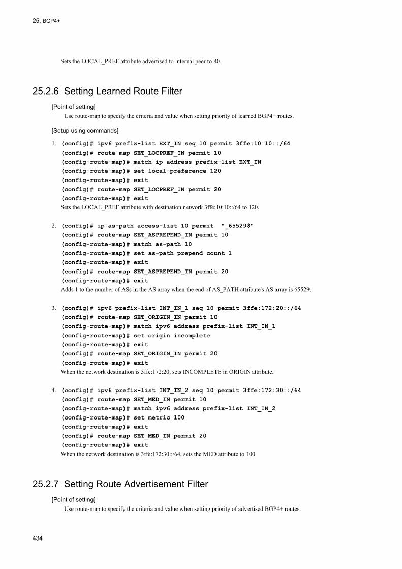
25. BGP4+
Sets the LOCAL_PREF attribute advertised to internal peer to 80.
25.2.6 Setting Learned Route Filter[Point of setting]
Use route-map to specify the criteria and value when setting priority of learned BGP4+ routes.
[Setup using commands]
1. (config)# ipv6 prefix-list EXT_IN seq 10 permit 3ffe:10:10::/64
(config)# route-map SET_LOCPREF_IN permit 10
(config-route-map)# match ip address prefix-list EXT_IN
(config-route-map)# set local-preference 120
(config-route-map)# exit
(config)# route-map SET_LOCPREF_IN permit 20
(config-route-map)# exit
Sets the LOCAL_PREF attribute with destination network 3ffe:10:10::/64 to 120.
2. (config)# ip as-path access-list 10 permit "_65529$"
(config)# route-map SET_ASPREPEND_IN permit 10
(config-route-map)# match as-path 10
(config-route-map)# set as-path prepend count 1
(config-route-map)# exit
(config)# route-map SET_ASPREPEND_IN permit 20
(config-route-map)# exit
Adds 1 to the number of ASs in the AS array when the end of AS_PATH attribute's AS array is 65529.
3. (config)# ipv6 prefix-list INT_IN_1 seq 10 permit 3ffe:172:20::/64
(config)# route-map SET_ORIGIN_IN permit 10
(config-route-map)# match ipv6 address prefix-list INT_IN_1
(config-route-map)# set origin incomplete
(config-route-map)# exit
(config)# route-map SET_ORIGIN_IN permit 20
(config-route-map)# exit
When the network destination is 3ffe:172:20, sets INCOMPLETE in ORIGIN attribute.
4. (config)# ipv6 prefix-list INT_IN_2 seq 10 permit 3ffe:172:30::/64
(config)# route-map SET_MED_IN permit 10
(config-route-map)# match ipv6 address prefix-list INT_IN_2
(config-route-map)# set metric 100
(config-route-map)# exit
(config)# route-map SET_MED_IN permit 20
(config-route-map)# exit
When the network destination is 3ffe:172:30::/64, sets the MED attribute to 100.
25.2.7 Setting Route Advertisement Filter[Point of setting]
Use route-map to specify the criteria and value when setting priority of advertised BGP4+ routes.
434

25. BGP4+
[Setup using commands]
1. (config)# ipv6 prefix-list MY_NET_1 seq 10 permit 3ffe:192:169:10::/64
(config)# ipv6 prefix-list MY_NET_2 seq 10 permit 3ffe:192:169:20::/64
(config)# route-map SET_EXT_OUT permit 10
(config-route-map)# match ipv6 address prefix-list MY_NET_1
(config-route-map)# set metric 120
(config-route-map)# exit
(config)# route-map SET_EXT_OUT permit 20
(config-route-map)# match ipv6 address prefix-list MY_NET_2
(config-route-map)# exit
When the network destination is 3ffe:192:169:10::/64, sets the MED attribute to 120.Destination network 3ffe:192:169:20::/64 is also advertised.
25.2.8 Setting Learned Route Filtering Criteria[Point of setting]
Specify the filter with neighbor in to apply learning filter to each peer.
[Setup using commands]
1. (config)#router bgp 65531
(config-router)# address-family ipv6
(config-router-af)# neighbor 3ffe:172:16:2::2 route-map SET_LOCPREF_IN in
Sets the LOCAL_PREF attribute of the route with 3ffe:10:10.::/64 as the destination network learned from peer (remote address: 3ffe:172:16:2::2) to 120 and gives priority over routes learned from other peers.
2. (config-router-af)# neighbor 3ffe:10:2:2::2 route-map SET_ASPREPEND_IN in
When the end of the AS array of the AS_PATH attribute learned from peer (remote address: 3ffe:10:2:2::2) is 65529, adds 1 to the number of ASs in the AS array and gives it less priority than routes learned from other priority.
3. (config-router-af)# neighbor 3ffe:10:1:2::2 route-map SET_ORIGIN_IN in
Sets the ORIGIN attribute of the route with 3ffe:172:20:0::/64 as the destination network learned from peer (remote address: 3ffe:10:1:2::2) to INCOMPLETE and gives it less priority than routes learned from other peers.
4. (config-router-af)# neighbor 3ffe:192:168:2::2 route-map SET_MED_IN in
Sets the MED attribute of the route with 3ffe:172:30::/64 as the destination network learned from peer (remote address: 3ffe:192:168:2::2) to 100.
25.2.9 Setting Route Advertisement Filtering Criteria[Point of setting]
Specify the filter with distribute-list out to apply the same route advertisement filter to all peers.
[Setup using commands]
1. (config-router-af)# distribute-list route-map SET_EXT_OUT out
(config-router-af)# exit
(config-router)# exit
(config)# exit
435

25. BGP4+
Advertises the route with 192.169.10.0/24 and 192.169.20.0/24 as destination network to all external peers.
25.2.10 Applying Filter[Point of setting]
Use the operation command clear ipv6 bgp to apply the route filter set as learned route filtering criteria and route advertisement filtering criteria.
[Setup using commands]
1. #clear ipv6 bgp * both
Applies the learned route filter and route advertisement filter.
[Note]The operation command clear ipv6 bgp (* in, * out, and * both specified) applies the route filter modification and executes the route refresh function (see "25.4.5 Route Refresh"). When negotiation of the root refresh function is not successful, root refresh request for relearning of the route is not made, but change of the route filter is reflected.
436

25. BGP4+
25.3 Operation of Basic Function
25.3.1 List of Operation CommandsThe following table provides a list of basic function operation commands.
Table 25-7: List of Operation Commands
25.3.2 Checking Peer Type and Connection ModeThe following table corresponds to "Figure 25-8: Configuration Example of Connection". The peer connection information is displayed with the operation command show ipv6 bgp specifying the neighbors parameter. Specify the neighbors and detail parameter to display detailed information.
Figure 25-9: Execution Result of show ipv6 bgp Command (with neighbors Parameter Specified)
> show ipv6 bgp neighborsDate 2005/10/18 22:45:55 UTCPeer Address Peer AS Local Address Local AS Type Status3ffe:10:1:2::2 65531 3ffe:10:1:2::1 65531 Internal Established3ffe:192:168:2::2 65531 3ffe:192:168:2::1 65531 Internal Established3ffe:10:2:2::2 65533 3ffe:10:1:2::1 65531 External Established3ffe:172:16:2::2 65532 3ffe:172:16:2::1 65531 External Established
Command Description
show system Displays the operation state.
ping ipv6 Sends test packet to the system at specified IPv6 address to determine whether communication is enabled.
show netstat (netstat) Displays the state and statistics of a network.
show processes cpu unicast Displays the CPU usage of the unicast routing program.
restart unicast Restarts the unicast routing program.
show ipv6 bgp Displays BGP4+ protocol information.
clear ipv6 route Clears and re-enters IPv6 forwarding entry in hardware.
show ipv6 entry Displays detailed information on specific IPv6 unicast route.
show ipv6 route Displays the route information held in the routing table.
clear ipv6 bgp Clears BGP4+ session and BGP4+ protocol related information and filters receive/send route using the new BGP filter information. Also it reconnects the BGP4+ session disconnected due to the restriction on the number of BGP4+ routes to be learned.
437

25. BGP4+
Figure 25-10: Execution Result of show ipv6 bgp Command (with neighbors detail Parameter Specified)
> show ipv6 bgp neighbors detailDate 2005/10/17 15:52:14 UTCBGP Peer: 3ffe:10:1:2::2 , Remote AS: 65531Remote Router ID: 10.1.2.102 BGP Status: Established Holdtime: 180 , Keepalive: 60 Established Transitions: 1 Established Date: 2005/10/17 15:51:00 BGP Version: 4 Type: Internal Local Address: 3ffe:10:1:2::1 Local AS: 65531 Local Router ID: 192.168.1.100 Next Connect Retry: - Connect Retry Timer: - Last Keep Alive Sent: 15:52:00 Last Keep Alive Received: 15:52:00 BGP Message UpdateIn UpdateOut TotalIn TotalOut 0 0 2 4 BGP Capability Negotiation: <IPv6-Uni Refresh Refresh(v)> Send : <IPv6-Uni Refresh Refresh(v)> Receive: <IPv6-Uni Refresh Refresh(v)> Password: UnConfiguredBGP Peer: 3ffe:192:168:2::2 , Remote AS: 65531Remote Router ID: 192.168.1.102 BGP Status: Established Holdtime: 180 , Keepalive: 60 Established Transitions: 1 Established Date: 2005/10/17 15:50:43 BGP Version: 4 Type: Internal Local Address:3ffe:192:168:2::1 Local AS: 65531 Local Router ID: 192.168.1.100 Next Connect Retry: - Connect Retry Timer: - Last Keep Alive Sent: 15:51:43 Last Keep Alive Received: 15:51:43 BGP Message UpdateIn UpdateOut TotalIn TotalOut 0 0 2 4 BGP Capability Negotiation: <IPv6-Uni Refresh Refresh(v)> Send : <IPv6-Uni Refresh Refresh(v)> Receive: <IPv6-Uni Refresh Refresh(v)> Password: UnConfiguredBGP Peer: 3ffe:10:2:2::2 , Remote AS: 65533Remote Router ID: 10.2.2.102 BGP Status: Established Holdtime: 180 , Keepalive: 60 Established Transitions: 1 Established Date: 2005/10/17 15:50:30 BGP Version: 4 Type: External Local Address: 3ffe:10:1:2::1 Local AS: 65531 Local Router ID: 192.168.1.100 Next Connect Retry: - Connect Retry Timer: - Last Keep Alive Sent: 15:51:30 Last Keep Alive Received: 15:51:30 BGP Message UpdateIn UpdateOut TotalIn TotalOut 0 0 2 4 BGP Capability Negotiation: <IPv6-Uni Refresh> Send : <IPv6-Uni Refresh Refresh(v)> Receive: <IPv6-Uni Refresh Refresh(v)> Password: UnConfiguredBGP Peer: 3ffe:172:16:2::2 , Remote AS: 65532Remote Router ID: 172.16.1.102 BGP Status: Established Holdtime: 180 , Keepalive: 60 Established Transitions: 1 Established Date: 2005/10/17 15:49:35 BGP Version: 4 Type: External Local Address:3ffe172:16:2::1 Local AS: 65531 Local Router ID: 192.168.1.100 Next Connect Retry: - Connect Retry Timer: - Last Keep Alive Sent: 15:51:35 Last Keep Alive Received: 15:51:35 BGP Message UpdateIn UpdateOut TotalIn TotalOut 0 0 3 5 BGP Capability Negotiation: <IPv6-Uni Refresh Refresh(v)> Send : <IPv6-Uni Refresh Refresh(v)> Receive: <IPv6-Uni Refresh Refresh(v)> Password: UnConfigured>
25.3.3 Checking BGP4+ Route Selection ResultThe BGP4+ route selection result can be verified with the operation command show ipv6 bgp.
438
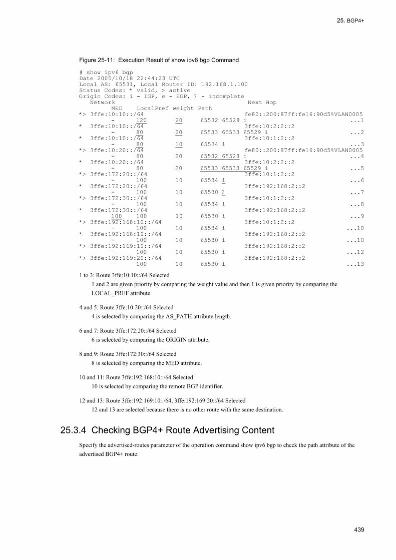
25. BGP4+
Figure 25-11: Execution Result of show ipv6 bgp Command
# show ipv6 bgpDate 2005/10/18 22:44:23 UTCLocal AS: 65531, Local Router ID: 192.168.1.100Status Codes: * valid, > activeOrigin Codes: i - IGP, e - EGP, ? - incomplete Network Next Hop MED LocalPref weight Path*> 3ffe:10:10::/64 fe80::200:87ff:fe16:90d5%VLAN0005 - 120 20 65532 65528 i ...1* 3ffe:10:10::/64 3ffe:10:2:2::2 - 80 20 65533 65533 65529 i ...2* 3ffe:10:10::/64 3ffe:10:1:2::2 - 80 10 65534 i ...3*> 3ffe:10:20::/64 fe80::200:87ff:fe16:90d5%VLAN0005 - 80 20 65532 65528 i ...4* 3ffe:10:20::/64 3ffe:10:2:2::2 - 80 20 65533 65533 65529 i ...5*> 3ffe:172:20::/64 3ffe:10:1:2::2 - 100 10 65534 i ...6* 3ffe:172:20::/64 3ffe:192:168:2::2 - 100 10 65530 ? ...7*> 3ffe:172:30::/64 3ffe:10:1:2::2 - 100 10 65534 i ...8* 3ffe:172:30::/64 3ffe:192:168:2::2 100 100 10 65530 i ...9*> 3ffe:192:168:10::/64 3ffe:10:1:2::2 - 100 10 65534 i ...10* 3ffe:192:168:10::/64 3ffe:192:168:2::2 - 100 10 65530 i ...10*> 3ffe:192:169:10::/64 3ffe:192:168:2::2 - 100 10 65530 i ...12*> 3ffe:192:169:20::/64 3ffe:192:168:2::2 - 100 10 65530 i ...13
1 to 3: Route 3ffe:10:10::/64 Selected1 and 2 are given priority by comparing the weight value and then 1 is given priority by comparing the LOCAL_PREF attribute.
4 and 5: Route 3ffe:10:20::/64 Selected4 is selected by comparing the AS_PATH attribute length.
6 and 7: Route 3ffe:172:20::/64 Selected6 is selected by comparing the ORIGIN attribute.
8 and 9: Route 3ffe:172:30::/64 Selected8 is selected by comparing the MED attribute.
10 and 11: Route 3ffe:192:168:10::/64 Selected10 is selected by comparing the remote BGP identifier.
12 and 13: Route 3ffe:192:169:10::/64, 3ffe:192:169:20::/64 Selected12 and 13 are selected because there is no other route with the same destination.
25.3.4 Checking BGP4+ Route Advertising ContentSpecify the advertised-routes parameter of the operation command show ipv6 bgp to check the path attribute of the advertised BGP4+ route.
439

25. BGP4+
Figure 25-12: Execution Result of show ipv6 bgp Command (with advertised-routes Parameter Specified)
> show ipv6 bgp advertised-routesDate 2005/10/18 22:44:54 UTCBGP4+ Peer: 3ffe:10:2:2::2 , Remote AS: 65533Local AS: 65531, Local Router ID: 192.168.1.100Origin Codes: i - IGP, e - EGP, ? - incompleteNetwork Next Hop MED LocalPref Path3ffe:192:169:10::/64 3ffe:192:168:2::2 120 - 65531 i ...13ffe:192:169:20::/64 3ffe:192:168:2::2 100 - 65531 iBGP4+ Peer: 3ffe:172:16:2::2 , Remote AS: 65532Local AS: 65531, Local Router ID: 192.168.1.100Origin Codes: i - IGP, e - EGP, ? - incompleteNetwork Next Hop MED LocalPref Path3ffe:192:169:10::/64 3ffe:192:168:2::2 120 - 65531 i ...23ffe:192:169:20::/64 3ffe:192:168:2::2 100 - 65531 i
1 and 2: MED attribute (value: 120) is set in advertised route.
440
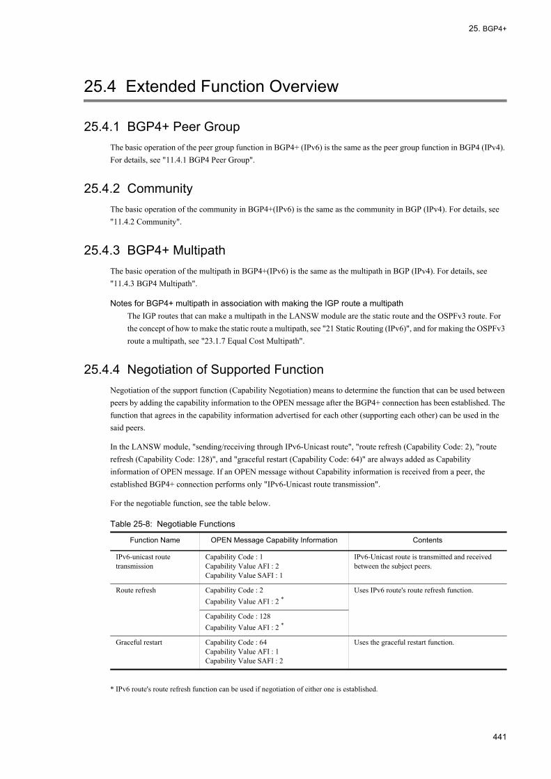
25. BGP4+
25.4 Extended Function Overview
25.4.1 BGP4+ Peer GroupThe basic operation of the peer group function in BGP4+ (IPv6) is the same as the peer group function in BGP4 (IPv4). For details, see "11.4.1 BGP4 Peer Group".
25.4.2 CommunityThe basic operation of the community in BGP4+(IPv6) is the same as the community in BGP (IPv4). For details, see "11.4.2 Community".
25.4.3 BGP4+ MultipathThe basic operation of the multipath in BGP4+(IPv6) is the same as the multipath in BGP (IPv4). For details, see "11.4.3 BGP4 Multipath".
Notes for BGP4+ multipath in association with making the IGP route a multipathThe IGP routes that can make a multipath in the LANSW module are the static route and the OSPFv3 route. For the concept of how to make the static route a multipath, see "21 Static Routing (IPv6)", and for making the OSPFv3 route a multipath, see "23.1.7 Equal Cost Multipath".
25.4.4 Negotiation of Supported FunctionNegotiation of the support function (Capability Negotiation) means to determine the function that can be used between peers by adding the capability information to the OPEN message after the BGP4+ connection has been established. The function that agrees in the capability information advertised for each other (supporting each other) can be used in the said peers.
In the LANSW module, "sending/receiving through IPv6-Unicast route", "route refresh (Capability Code: 2), "route refresh (Capability Code: 128)", and "graceful restart (Capability Code: 64)" are always added as Capability information of OPEN message. If an OPEN message without Capability information is received from a peer, the established BGP4+ connection performs only "IPv6-Unicast route transmission".
For the negotiable function, see the table below.
Table 25-8: Negotiable Functions
* IPv6 route's route refresh function can be used if negotiation of either one is established.
Function Name OPEN Message Capability Information Contents
IPv6-unicast route transmission
Capability Code : 1Capability Value AFI : 2Capability Value SAFI : 1
IPv6-Unicast route is transmitted and received between the subject peers.
Route refresh Capability Code : 2Capability Value AFI : 2 *
Uses IPv6 route's route refresh function.
Capability Code : 128Capability Value AFI : 2 *
Graceful restart Capability Code : 64Capability Value AFI : 1Capability Value SAFI : 2
Uses the graceful restart function.
441

25. BGP4+
Also, the following figure shows the concept of negotiation operation.
Figure 25-13: Operational Concept of Negotiation
25.4.5 Route RefreshRoute refresh is a function that operates in BGP4+ based on the differential UPDATE (which advertises only the route that occurs with change), to force to re-advertise a route that has already been advertised.
The route refresh function consists of a function to re-advertise the route from the local system and a function to re-advertise the route from the mate system which is the BGP4+ peer. In addition, it is possible to select the type of route to re-advertise. This function is executed with the clear ipv6 bgp command.
The following table shows the route refresh functions.
Table 25-9: Route Refresh Function
The following figures shows the operating concept of the route refresh function.
Function Type Route Type Re-advertising Direction
Re-transmission of the IPv6-Unicast route
IPv6 unicast route Re-advertises the route on the mate system peered from the local system side.
Re-reception of the IPv6-Unicast route
Specifies the local system to re-advertise the route from the peered mate system.
442

25. BGP4+
Figure 25-14: Operational Concept of Route Refresh Function
(1) Note on employing route refresh
For retransmission of the route from the mate system side, both routers that have been peered must support the route refresh function. Whether or not the route refresh function can be used is decided by negotiation between the routers for both systems when the BGP4+ peer has been established.
Also, if the inbound parameter is specified with the configuration command neighbor soft-reconfiguration, route refresh request for route re-advertisement from the mate system to local system is not performed because the route suppressed with the learned route filter is retained as invalid route.
The route refresh function of the LANSW module conforms to RFC2918. The route refresh Capability code used for negotiation is RFC2918 compliant code (value=2) and private code (value=128). In addition, a private Capability code (value=128 to 255) defined in RFC2434 may also be used by other vendors.
Pay attention when using a refresh function between the LANSW module and other systems.
25.4.6 TCP MD5 AuthenticationThe basic action of TCP MD5 by BGP4+ (IPv6) is the same as TCP MD5 authentication by BGP (IPv4). For details, see "11.4.6 TCP MD5 Authentication".
25.4.7 BGP4+ Advertisement Route GenerationThe basic operation of a route generation function in BGP4+ (IPv6) is the same as that of a route generation function in bgp4 (IPv4). For details, see "11.4.7 BGP4 Advertisement Route Generation".
25.4.8 Route Flap DampeningThe basic operation of the route flap dampening in BGP4+ (IPv6) is the same as the route flap dampening in BGP4 (IPv4). For details, see "11.4.8 Route Flap Dampening".
25.4.9 Route ReflectionThe basic operation of the route reflection in BGP4+ (IPv6) is the same as the route reflection in BGP4 (IPv4). For details, see "11.4.9 Route Reflection".
443

25. BGP4+
25.4.10 ConfederationThe basic operation of the confederation in BGP4+ (IPv6) is the same as the confederation in BGP4 (IPv4). For details, see "11.4.10 Confederation".
25.4.11 Graceful RestartThe basic operation of the graceful restart in BGP4+ (IPv6) is the same as the graceful restart in BGP4 (IPv4). For details, see "11.4.11 Graceful Restart".
25.4.12 BGP4+ Learned Route RestrictionThe basic operation of the restriction on the number of learned routes in BGP4+ (IPv6) is the same as the restriction in BGP4 (IPv4). For details, see "11.4.12 BGP4 Learned Route Restriction".
444
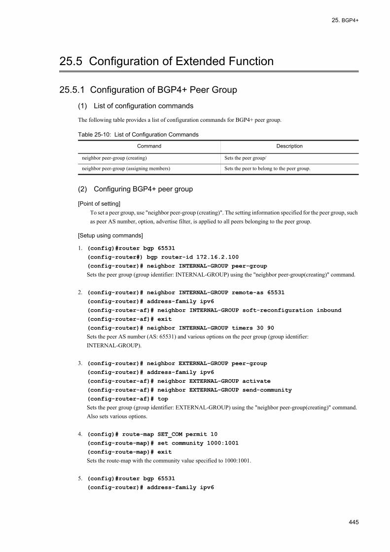
25. BGP4+
25.5 Configuration of Extended Function
25.5.1 Configuration of BGP4+ Peer Group
(1) List of configuration commands
The following table provides a list of configuration commands for BGP4+ peer group.
Table 25-10: List of Configuration Commands
(2) Configuring BGP4+ peer group
[Point of setting]To set a peer group, use "neighbor peer-group (creating)". The setting information specified for the peer group, such as peer AS number, option, advertise filter, is applied to all peers belonging to the peer group.
[Setup using commands]
1. (config)#router bgp 65531
(config-router#) bgp router-id 172.16.2.100
(config-router)# neighbor INTERNAL-GROUP peer-group
Sets the peer group (group identifier: INTERNAL-GROUP) using the "neighbor peer-group(creating)" command.
2. (config-router)# neighbor INTERNAL-GROUP remote-as 65531
(config-router)# address-family ipv6
(config-router-af)# neighbor INTERNAL-GROUP soft-reconfiguration inbound
(config-router-af)# exit
(config-router)# neighbor INTERNAL-GROUP timers 30 90
Sets the peer AS number (AS: 65531) and various options on the peer group (group identifier: INTERNAL-GROUP).
3. (config-router)# neighbor EXTERNAL-GROUP peer-group
(config-router)# address-family ipv6
(config-router-af)# neighbor EXTERNAL-GROUP activate
(config-router-af)# neighbor EXTERNAL-GROUP send-community
(config-router-af)# top
Sets the peer group (group identifier: EXTERNAL-GROUP) using the "neighbor peer-group(creating)" command. Also sets various options.
4. (config)# route-map SET_COM permit 10
(config-route-map)# set community 1000:1001
(config-route-map)# exit
Sets the route-map with the community value specified to 1000:1001.
5. (config)#router bgp 65531
(config-router)# address-family ipv6
Command Description
neighbor peer-group (creating) Sets the peer group/
neighbor peer-group (assigning members) Sets the peer to belong to the peer group.
445
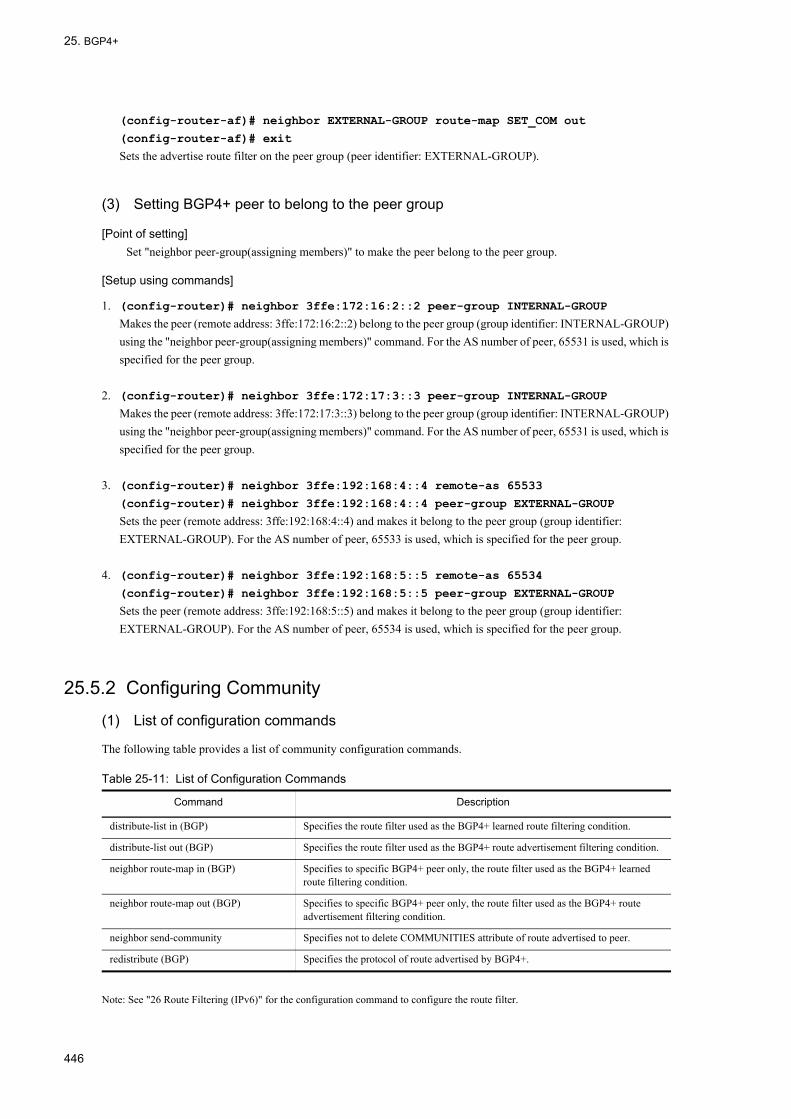
25. BGP4+
(config-router-af)# neighbor EXTERNAL-GROUP route-map SET_COM out
(config-router-af)# exit
Sets the advertise route filter on the peer group (peer identifier: EXTERNAL-GROUP).
(3) Setting BGP4+ peer to belong to the peer group
[Point of setting]Set "neighbor peer-group(assigning members)" to make the peer belong to the peer group.
[Setup using commands]
1. (config-router)# neighbor 3ffe:172:16:2::2 peer-group INTERNAL-GROUP
Makes the peer (remote address: 3ffe:172:16:2::2) belong to the peer group (group identifier: INTERNAL-GROUP) using the "neighbor peer-group(assigning members)" command. For the AS number of peer, 65531 is used, which is specified for the peer group.
2. (config-router)# neighbor 3ffe:172:17:3::3 peer-group INTERNAL-GROUP
Makes the peer (remote address: 3ffe:172:17:3::3) belong to the peer group (group identifier: INTERNAL-GROUP) using the "neighbor peer-group(assigning members)" command. For the AS number of peer, 65531 is used, which is specified for the peer group.
3. (config-router)# neighbor 3ffe:192:168:4::4 remote-as 65533
(config-router)# neighbor 3ffe:192:168:4::4 peer-group EXTERNAL-GROUP
Sets the peer (remote address: 3ffe:192:168:4::4) and makes it belong to the peer group (group identifier: EXTERNAL-GROUP). For the AS number of peer, 65533 is used, which is specified for the peer group.
4. (config-router)# neighbor 3ffe:192:168:5::5 remote-as 65534
(config-router)# neighbor 3ffe:192:168:5::5 peer-group EXTERNAL-GROUP
Sets the peer (remote address: 3ffe:192:168:5::5) and makes it belong to the peer group (group identifier: EXTERNAL-GROUP). For the AS number of peer, 65534 is used, which is specified for the peer group.
25.5.2 Configuring Community
(1) List of configuration commands
The following table provides a list of community configuration commands.
Table 25-11: List of Configuration Commands
Note: See "26 Route Filtering (IPv6)" for the configuration command to configure the route filter.
Command Description
distribute-list in (BGP) Specifies the route filter used as the BGP4+ learned route filtering condition.
distribute-list out (BGP) Specifies the route filter used as the BGP4+ route advertisement filtering condition.
neighbor route-map in (BGP) Specifies to specific BGP4+ peer only, the route filter used as the BGP4+ learned route filtering condition.
neighbor route-map out (BGP) Specifies to specific BGP4+ peer only, the route filter used as the BGP4+ route advertisement filtering condition.
neighbor send-community Specifies not to delete COMMUNITIES attribute of route advertised to peer.
redistribute (BGP) Specifies the protocol of route advertised by BGP4+.
446

25. BGP4+
(2) Community configuration
[Point of setting]In order to add COMMUNITIES attribute to the advertised BGP4+ route, use the configuration command neighbor send-community for the corresponding peer.
[Setup using commands]
1. (config)#router bgp 65531
(config-router#) bgp router-id 192.168.1.100
(config-router)# neighbor 3ffe:192:168:2::2 remote-as 65531
(config-router)# neighbor 3ffe:172:16:2::2 remote-as 65532
(config-router)# neighbor 3ffe:10:2:2::2 remote-as 65533
Sets the BGP4+ peer.
2. (config-router)# address-family ipv6
Moves to config-router-af mode.
3. (config-router-af)# neighbor 3ffe:172:16:2::2 send-community
(config-router-af)# neighbor 3ffe:172:17:2::2 send-community
(config-router-af)# exit
(config-router)# exit
Specifies the addition of COMMUNITIES attribute to BGP4+ route advertised to peer.
4. (config)# ip community-list 10 permit 1000:1002
(config)# ip community-list 20 permit 1000:1003
(config)# route-map SET_LOCPREF permit 10
(config-route-map)# match community 10
(config-route-map)# set local-preference 120
(config-route-map)# exit
(config)# route-map SET_LOCPREF permit 20
(config-route-map)# match community 20
(config-route-map)# set local-preference 80
(config-route-map)# exit
(config)# route-map SET_LOCPREF permit 30
(config-route-map)# exit
Sets the LOCAL_PREF attribute of route with COMMUNITIES attribute containing community value 1000:1002 to 120 and LOCAL_PREF attribute of route with COMMUNITIES attribute containing community value 1000:1003 to 80.
5. (config)# ipv6 prefix-list MY_NET seq 10 permit 3ffe:192:168::/48 ge 32 le 64
(config)# route-map SET_COM permit 10
(config-route-map)# match ipv6 address prefix-list MY_NET
(config-route-map)# set community 1000:1001
(config-route-map)# exit
Sets COMMUNITIES attribute that has community value 1000:1001 set in route with network destination 3ffe:192:168::/48 (prefix length 32 to 64).
6. (config)#router bgp 65531
(config-router)# address-family ipv6
(config-router-af)# distribute-list route-map SET_LOCPREF in
447

25. BGP4+
(config-router-af)# distribute-list route-map SET_COM out
Sets learned route filter and route advertisement filter of all peers.
7. (config-router-af)# neighbor 3ffe:192:168:2::2 activate
(config-router-af)# neighbor 3ffe:172:16:2::2 activate
(config-router-af)#neighbor 3ffe:10:2:2::2 activate
Enables IPv6 address family.
(3) Applying filter
[Point of setting]Use the operation command clear ipv6 bgp to apply the route filter as learned route filtering criteria and route advertisement filtering criteria.
[Setup using commands]
1. #clear ipv6 bgp * both
Applies route filter that uses community.
25.5.3 Configuring BGP4+ Multipath
(1) List of configuration commands
The following table provides a list of BGP4+ multipath configuration commands.
Table 25-12: List of Configuration Commands
(2) BGP4+ multipath configuration
[Point of setting]When specifying the all-as parameter for maximum-paths, set bgp always-compare-med in advance.
[Setup using commands]
1. (config)#router bgp 65531
(config-router#) bgp router-id 192.168.1.100
(config-router)# neighbor 3ffe:172:16:2::2 remote-as 65532
(config-router)# neighbor 3ffe:172:17:2::2 remote-as 65533
Sets the peers forming an multipath. In this example, a multipath is formed between routes learned from AS65532 and AS65533.
2. (config-router)# address-family ipv6
Moves to config-router-af mode.
3. (config-router-af)# bgp always-compare-med
(config-router-af)# maximum-paths 4 all-as
Command Description
bgp always-compare-med Sets to configure MED attributes learned from different ASs (if this command is not set, the all-as parameter of the maximum-path command cannot be specified).
maximum-paths Sets multipath.
448

25. BGP4+
Specifies to form a multipath of up to four paths including routes learned from different ASs.
4. (config-router-af)# neighbor 3ffe:172:16:2::2 activate
(config-router-af)# neighbor 3ffe:172:17:2::2 activate
Enables IPv6 address family.
25.5.4 Configuring TCP MD5 Authentication
(1) List of configuration commands
The following table provides a list of TCP MD5 authentication (BGP4+) configuration commands.
Table 25-13: List of Configuration Commands
(2) TCP MD5 authentication configuration
[Point of setting]Use the configuration command neighbor password with authentication key to set TCP MD5 authentication.
[Setup using commands]
1. (config)#router bgp 65531
(config-router#) bgp router-id 192.168.1.100
(config-router)# neighbor 3ffe:172:16:2::2 remote-as 65532
(config-router)# neighbor 3ffe:192:168:2::2 remote-as 65531
Sets the BGP4+ peer.
2. (config-router)# neighbor 3ffe:172:16:2::2 password "authmd5_65532"
Sets TCP MD5 authentication with authentication key "authmd5_65532" to peer with remote address 3ffe:172:16:2::2.
3. (config-router)# address-family ipv6
Moves to config-router-af mode.
4. (config-router-af)# neighbor 3ffe:172:16:2::2 activate
(config-router-af)# neighbor 3ffe:192:168:2::2 activate
Enables IPv6 address family.
25.5.5 Configuring BGP4+ Advertisement Route Generation
(1) List of configuration commands
The following table provides a list of BGP4+ advertisement generation configuration commands.
Table 25-14: List of Configuration Commands
Command Description
neighbor password Sets to apply TCP MD5 authentication for connection with peer.
Command Description
network Sets to generate BGP4+ advertisement route.
449

25. BGP4+
(2) BGP4+ connection information configuration
[Point of setting]Use the configuration command network to generate BGP4+ advertisement route. Specify local with the route-map match route-type command to advertise route generated with the network command.
[Setup using commands]
1. (config)#router bgp 65531
(config-router#) bgp router-id 192.168.1.100
(config-router)# neighbor 3ffe:172:16:2::2 remote-as 65532
(config-router)# neighbor 3ffe:192:168:2::2 remote-as 65531
Sets the BGP4+ peer.
2. (config-router)# address-family ipv6
Moves to config-router-af mode.
3. (config-router-af)# network 3ffe:192:169:10::/64 ge 48 le 64
(config-router-af)# network 3ffe:173:16::/48 le 64
(config-router-af)# exit
When there is a route with mask length 48 to 64 matching the prefix 3ffe:192:169:10:: in the routing table, the LANSW module generates BGP4+ advertisement for 3ffe:192:169:10::/64.Similarly, when there is a route with mask length 48 to 64 matching the prefix 3ffe:173:16:: in the routing table, the LANSW module generates BGP4+ advertisement for 3ffe:173:16::/48.
4. (config)# route-map ADV_NET permit 10
(config-route-map)# match route-type local
(config-route-map)# exit
Specifies the generated BGP4+ advertising route.
5. (config)#router bgp 65531
(config-router)# address-family ipv6
(config-router-af#) neighbor 3ffe:172:16:2::2 route-map ADV_NET out
Specifies the advertisement of generated BGP4+ advertisement route to peer with remote address 3ffe:172:16:2::2.
6. (config-router-af)# neighbor 3ffe:172:16:2::2 activate
(config-router-af)# neighbor 3ffe:192:168:2::2 activate
Enables IPv6 address family.
(3) Applying filter
[Point of setting]To advertise the generated BGP4+ advertisement route, use the operation command clear ipv6 bgp and apply the filter.
[Setup using commands]
1. #clear ipv6 bgp * out
Applies route filter specifying the BGP4+ advertisement route.
450

25. BGP4+
25.5.6 Configuring Route Flap Dampening
(1) List of configuration commands
The following table lists the configuration commands for route flap dampening.
Table 25-15: List of Configuration Commands
(2) Setting the route flap dampening
[Point of setting]To apply the route flap dampening to BGP4+ routes, set the "bgp dampening" command in config-router-af mode.
[Setup using commands]
1. (config)#router bgp 65531
(config-router#) bgp router-id 192.168.1.100
(config-router)# neighbor 3ffe:172:16:2::2 remote-as 65532
(config-router)# neighbor 3ffe:172:17:2::2 remote-as 65533
Sets the BGP4+ peer.
2. (config-router)#address-family ipv6
Moves to config-router-af mode.
3. (config-router-af)# bgp dampening
Applies the route flap dampening.
4. (config-router-af)#neighbor 3ffe:172:16:2::2 activate
(config-router-af)# neighbor 3ffe:172:17:2::2 activate
Enables IPv6 address family.
25.5.7 Configuring Route ReflectionThe explanation of the configuration is provided based on the example shown in the figure below.
Command Description
bgp dampening Inhibits the route with flap temporarily to reduce the influence by route flap.
451

25. BGP4+
Figure 25-15: Configuration Example of Route Reflection
(1) List of configuration commands
The following table lists the configuration commands for the route reflection.
Table 25-16: List of Configuration Commands
(2) Setting the route reflection
[Point of setting]The setting is not required as the "bgp client-to-client reflection" command is enabled by default. To disable the BGP4+ route reflection between the route reflector clients, specify "no bgp client-to-client reflection" command in config-router-af mode.
[Setup using commands]
1. (config)#router bgp 65531
(config-router#) bgp router-id 192.168.1.100
(config-router)# neighbor 3ffe:172:16:2::2 remote-as 65532
(config-router)# neighbor 3ffe:192:168:2::2 remote-as 65531
(config-router)# neighbor 3ffe:192:168:3::2 remote-as 65531
(config-router)# neighbor 3ffe:192:168:4::2 remote-as 65531
(config-router)# neighbor 3ffe:192:168:5::2 remote-as 65531
Sets the BGP4+ peer by specifying router 1 as external peer and routers 2 to 5 as internal peers.
2. (config-router#) bgp cluster-id 10.1.2.1
Command Description
bgp client-to-client reflection Specifies to reflect the BGP4+ routes between the route reflector clients.
bgp cluster-id Specifies the cluster ID to be used for route reflection.
bgp router-id Specifies an ID used as the cluster ID of router reflection when bgp cluster-id is not specified.
neighbor route-reflector-client Specifies the route reflector client.
neighbor always-nexthop-self Specifies to force to overwrite the NEXT-HOP attribute of the route advertised to internal peer to the local side address used for peering with internal peer (including the case of route reflection).
452

25. BGP4+
Sets the cluster ID.
3. (config-router)# address-family ipv6
Moves to config-router-af mode.
4. (config-router-af)# neighbor 3ffe:192:168:2::2 route-reflector-client
(config-router-af)# neighbor 3ffe:192:168:3::2 route-reflector-client
(config-router-af)# neighbor 3ffe:192:168:4::2 route-reflector-client
Specifies routes 2 to 4 as route reflector clients.
5. (config-router-af)#neighbor 3ffe:172:16:2::2 activate
(config-router-af)# neighbor 3ffe:192:168:2::2 activate
(config-router-af)# neighbor 3ffe:192:168:3::2 activate
(config-router-af)# neighbor 3ffe:192:168:4::2 activate
(config-router-af)# neighbor 3ffe:192:168:5::2 activate
Enables IPv6 address family.
25.5.8 Configuring ConfederationThe explanation of the configuration is provided based on the example shown in the figure below.
Figure 25-16: Configuration Example of Confederation
(1) List of configuration commands
The following table lists the configuration commands for confederation.
Table 25-17: List of Configuration Commands
Command Description
bgp confederation identifier Specifies the local confederation AS number when confederation is configured.
bgp confederation peers Specifies the member AS number to connect when confederation is configured.
neighbor remote-as Sets BGP4/BGP4+ peer. Specifies the local member AS number to connect when confederation is configured.
453

25. BGP4+
(2) Setting the confederation
[Point of setting]Specify the local member AS number with "router bgp", and set the "bgp confederation peers" command on other member AS numbers to connect in config-router mode.
[Setup using commands]
1. (config)#router bgp 64512
Specifies the local member AS number (64512).
2. (config-router#) bgp router-id 192.168.1.100
Specifies the router ID.
3. (config-router)# bgp confederation identifier 65531
Specifies the local confederation AS number (65531).
4. (config-router)# bgp confederation peers 64513 64514
Specifies other member AS numbers (64513, 64514) to connect.
5. (config-router)# neighbor 3ffe:172:16:2::2 remote-as 65532
(config-router)# neighbor 3ffe:192:168:2::2 remote-as 64512
(config-router)# neighbor 3ffe:192:168:3::2 remote-as 64512
(config-router)# neighbor 3ffe:192:168:4::2 remote-as 64513
(config-router)# neighbor 3ffe:192:168:5::2 remote-as 64514
Sets the BGP4+ peer by specifying router 1 as external peer, routers 2 and 3 as internal peers, and routers 4 and 5 as member AS peers.
6. (config-router)# address-family ipv6
Moves to config-router-af mode.
7. (config-router-af)#neighbor 3ffe:172:16:2::2 activate
(config-router-af)# neighbor 3ffe:192:168:2::2 activate
(config-router-af)# neighbor 3ffe:192:168:3::2 activate
(config-router-af)# neighbor 3ffe:192:168:4::2 activate
(config-router-af)# neighbor 3ffe:192:168:5::2 activate
Enables IPv6 address family.
25.5.9 Configuring Graceful Restart
(1) List of configuration commands
The graceful restart configuration command list is shown in the table below.
Table 25-18: List of Configuration Commands
Command Description
bgp graceful-restart mode Specifies the graceful restart function to be used.
454

25. BGP4+
(2) Setting the graceful restart
[Point of setting]To use the graceful restart function, set the "bgp graceful-restart mode" command in config-router mode.
[Setup using commands]
1. (config)#router bgp 65531
(config-router#) bgp router-id 192.168.1.100
(config-router)# neighbor 3ffe:172:16:2::2 remote-as 65532
(config-router)# neighbor 3ffe:192:168:2::2 remote-as 65531
Sets the BGP4+ peer.
2. (config-router)# bgp graceful-restart mode receive
Specifies the graceful restart receive router function to be used.
3. (config-router)# address-family ipv6
Moves to config-router-af mode.
4. (config-router-af)# neighbor 3ffe:172:16:2::2 activate
(config-router-af)# neighbor 3ffe:192:168:2::2 activate
Enables IPv6 address family.
25.5.10 Configuring BGP4+ Learned Route Restriction
(1) List of configuration commands
The following table provides a list of configuration commands for BGP4+ learned route restriction.
Table 25-19: List of Configuration Commands
(2) Setting the restriction on the number of BGP4+ learned routes
[Point of setting]To apply the limitation on the number of BGP4+ learned routes to the peer, set the "neighbor maximum-prefix" command.
[Setup using commands]
1. (config)#router bgp 65531
(config-router#) bgp router-id 192.168.1.100
(config-router)# neighbor 3ffe:172:16:2::2 remote-as 65532
(config-router)# neighbor 3ffe:192:168:2::2 remote-as 65531
bgp graceful-restart restart-time Specifies the maximum duration of time to reconnect the peer after the neighboring router starts the graceful restart.
bgp graceful-restart stalepath-time Specifies the maximum duration of time to retain the previous route after the neighboring router starts the graceful restart.
Command Description
neighbor maximum-prefix Limits the number of routes to be learned from the corresponding peer.
Command Description
455

25. BGP4+
Sets the BGP4+ peer.
2. (config-router)# address-family ipv6
Moves to config-router-af mode.
3. (config-router-af)# neighbor 3ffe:172:16:2::2 maximum-prefix 1000 80 restart
60
Sets the upper limit to 1000 for the number of routes to be learned form the external peer (remote address: 3ffe:172:16:2::2), the alarming operation message output threshold to 80%, and the restart time to 60 minutes for reconnecting the disconnected peer after it exceeds the upper limit.
4. (config-router-af)# neighbor 3ffe:192:168:2::2 maximum-prefix 100 warning-only
Sets the upper limit to 100 for the number of routes to be learned form the internal peer (remote address: 3ffe:172:16:2::2) and specifies not to disconnect the peer even if it exceeds the upper limit.
5. (config-router-af)#neighbor 3ffe:172:16:2::2 activate
(config-router-af)# neighbor 3ffe:192:168:2::2 activate
Enables IPv6 address family.
456
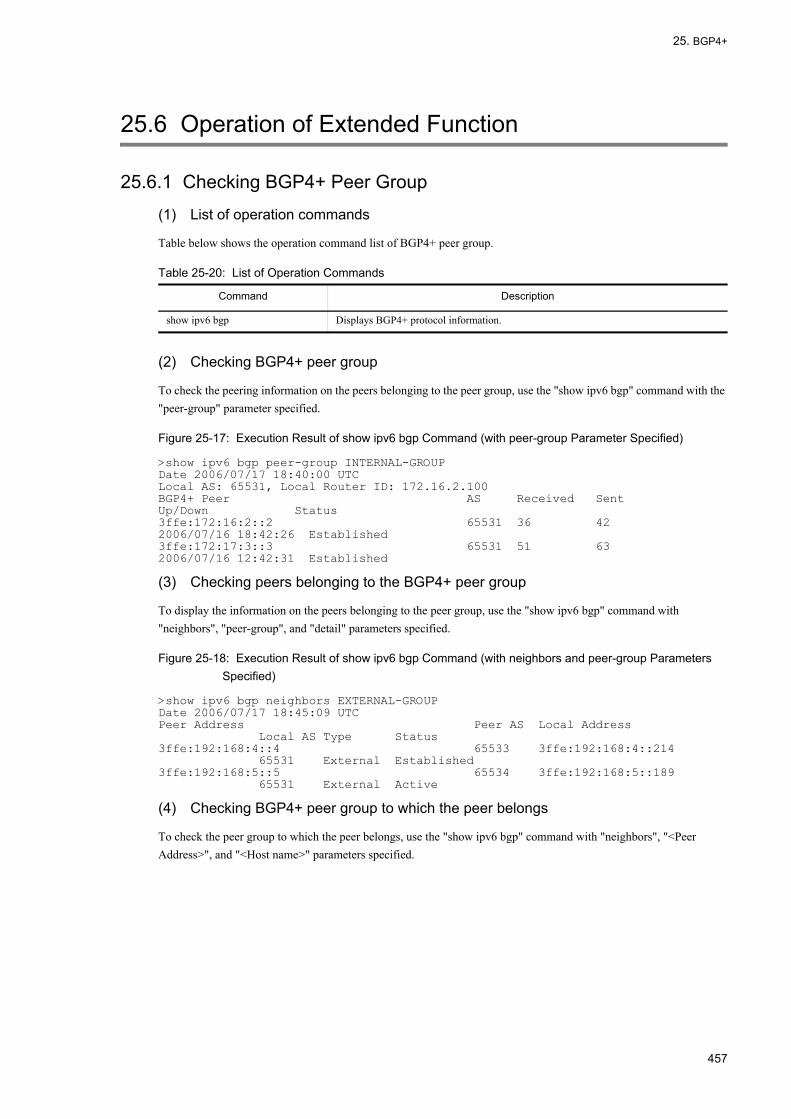
25. BGP4+
25.6 Operation of Extended Function
25.6.1 Checking BGP4+ Peer Group
(1) List of operation commands
Table below shows the operation command list of BGP4+ peer group.
Table 25-20: List of Operation Commands
(2) Checking BGP4+ peer group
To check the peering information on the peers belonging to the peer group, use the "show ipv6 bgp" command with the "peer-group" parameter specified.
Figure 25-17: Execution Result of show ipv6 bgp Command (with peer-group Parameter Specified)
>show ipv6 bgp peer-group INTERNAL-GROUPDate 2006/07/17 18:40:00 UTCLocal AS: 65531, Local Router ID: 172.16.2.100BGP4+ Peer AS Received Sent Up/Down Status3ffe:172:16:2::2 65531 36 42 2006/07/16 18:42:26 Established3ffe:172:17:3::3 65531 51 63 2006/07/16 12:42:31 Established
(3) Checking peers belonging to the BGP4+ peer group
To display the information on the peers belonging to the peer group, use the "show ipv6 bgp" command with "neighbors", "peer-group", and "detail" parameters specified.
Figure 25-18: Execution Result of show ipv6 bgp Command (with neighbors and peer-group Parameters Specified)
>show ipv6 bgp neighbors EXTERNAL-GROUPDate 2006/07/17 18:45:09 UTCPeer Address Peer AS Local Address Local AS Type Status3ffe:192:168:4::4 65533 3ffe:192:168:4::214 65531 External Established3ffe:192:168:5::5 65534 3ffe:192:168:5::189 65531 External Active
(4) Checking BGP4+ peer group to which the peer belongs
To check the peer group to which the peer belongs, use the "show ipv6 bgp" command with "neighbors", "<Peer Address>", and "<Host name>" parameters specified.
Command Description
show ipv6 bgp Displays BGP4+ protocol information.
457

25. BGP4+
Figure 25-19: Execution Result of show ipv6 bgp Command (with neighbors and <Peer Address> Parameters Specified)
>show ipv6 bgp neighbors 3ffe:172:16:2::2Date 2006/07/17 18:45:09 UTCBGP4+ Peer: 3ffe:172:16:2::2 , Remote AS: 65531Remote Router ID: 172.16.2.20, Peer Group: INTERNAL-GROUP ...1 BGP4+ Status:Established HoldTime: 90 , Keepalive: 30 Established Transitions: 1 Established Date: 2006/07/16 18:42:26 BGP4+ Version: 4 Type: Internal Local Address: 3ffe:172:16:2::214 Local AS: 65531 Local Router ID: 172.16.2.100 Next Connect Retry:-, Connect Retry Timer: - Last Keep Alive Sent: 18:42:20, Last Keep Alive Received: 18:42:20 BGP4+ Message UpdateIn UpdateOut TotalIn TotalOut 12 14 36 42 BGP4+ Capability Negotiation: <Refresh Refresh(v) IPv6-Uni> Send : <Refresh Refresh(v) IPv6-Uni> Receive: <Refresh Refresh(v) IPv6-Uni> Password: UnConfigured
1. The peer belongs to the INTERNAL-GROUP peer group.
25.6.2 Checking Community
(1) List of operation commands
The following table provides a list of community operation commands.
Table 25-21: List of Operation Commands
(2) Displaying learned route community
The following table corresponds to "25.5.2 Configuring Community".
Specify the community parameter of the show ipv6 bgp command to display a route with specific community.
Figure 25-20: Execution Result of show ipv6 bgp Command (with community Parameter Specified)
> show ipv6 bgp community 1000:1002Date 2005/10/20 21:00:00 UTCLocal AS: 65531, Local Router ID: 192.168.1.100Status Codes: d dampened, * valid, > active, S StaleOrigin Codes: i - IGP, e - EGP, ? - incompleteNetwork NextHop MED LocalPref Weight Path*> 3ffe:10:10::/64 fe80::200:87ff:fe16:90d5%VLAN0005 - 100 0 65532 i*> 3ffe:10:20::/64 fe80::200:87ff:fe16:90d5%VLAN0005 - 100 0 65532 i
Specify the route parameter of the show ipv6 bgp command to display the community a route has.
Command Description
show ipv6 route Displays the route information held in the routing table.
show ipv6 bgp Displays BGP4+ protocol information.
458

25. BGP4+
Figure 25-21: Execution Result of show ipv6 bgp Command (with route Parameter Specified)
> show ipv6 bgp route 3ffe:10:10::/64Date 2005/10/20 21:09:12 UTCBGP Peer: 3ffe:172:16:2::2 , Remote AS: 65532Local AS: 65531, Local Router ID: 192.168.1.100Status Codes: * valid, > activeRoute 3ffe:10:10::/64*> Next Hop fe80::200:87ff:fe16:90d5%VLAN0005 MED: -, LocalPref: 100, Weight: 0, Type: External route Origin: IGP, IGP Metric: 0 Path: 65532 Communities: 1000:1002
(3) Displaying the learned route filtering result
The learning filtering result using the COMMUNITIES attribute is displayed using the operation command show ipv6 bgp.
Figure 25-22: Execution Result of show ipv6 bgp Command
> show ipv6 bgpDate 2005/10/20 21:10:09 UTCLocal AS: 65531, Local Router ID: 192.168.1.100Status Codes: * valid, > activeOrigin Codes: i - IGP, e - EGP, ? - incomplete Network Next Hop MED LocalPref weight Path*> 3ffe:10:10::/64 fe80::200:87ff:fe16:90d5%VLAN0005 - 120 0 65532 i* 3ffe:10:10::/64 3ffe:10:2:2::2 - 80 0 65533 i*> 3ffe:10:20::/64 fe80::200:87ff:fe16:90d5%VLAN0005 - 120 0 65532 i* 3ffe:10:20::/64 3ffe:10:2:2::2 - 80 0 65533 i*> 3ffe:192:169:10::/64 3ffe:192:168:2::2 - 100 0 i *> 3ffe:192:169:20::/64 3ffe:192:168:2::2 - 100 0 i
(4) Displaying advertised route community
The COMMUNITIES attribute of the advertised BGP4+ route is displayed by specifying the advertised-routes parameter of the show ipv6 bgp command.
Figure 25-23: Execution Result of show ipv6 bgp Command (with advertised-routes Parameter Specified)
> show ipv6 bgp advertised-routes 3ffe:192:169:10::/64Date 2005/10/18 22:44:54 UTCBGP Peer: 3ffe:10:2:2::2 , Remote AS: 65533Local AS: 65531, Local Router ID: 192.168.1.100Route 3ffe:192:169:10::/64*> Next Hop 3ffe:192:168:2::2 MED: -, LocalPref: -, Type: Internal route Origin: IGP Path: 65531 Next Hop Attribute: 3ffe:10:1:2::1 Communities: 1000:1001 BGP Peer: 3ffe:172:16:2::2 , Remote AS: 65532Local AS: 65531, Local Router ID: 192.168.1.100Route 3ffe:192:169:10::/64*> Next Hop 3ffe:192:168:2::2 MED: -, LocalPref: -, Type: Internal route Origin: IGP Path: 65531 Next Hop Attribute: 3ffe:172:16:2::1 fe80::200:87ff:fe21:90da Communities: 1000:1001
459

25. BGP4+
25.6.3 Checking BGP4+ Multipath
(1) List of operation commands
The following table provides a list of multipath operation commands.
Table 25-22: List of Operation Commands
(2) Displaying BGP4+ multipath
The following corresponds to "25.5.3 Configuring BGP4+ Multipath". Multipath configuration is displayed using show ipv6 route.
Figure 25-24: Execution Result of show ipv6 route Command
> show ipv6 routeDate 2005/10/28 21:47:11 UTCTotal: 13 routesDestination Next Hop Interface Metric Protocol Age::1/128 ::1 localhost 0/0 Connected 10m 51s3ffe:10:10::/64 fe80::5%VLAN0005 VLAN0005 -/- BGP4+ 4m 50s...1 fe80::6%VLAN0006 VLAN0006 - - -3ffe:10:20::/64 fe80::5%VLAN0005 VLAN0005 -/- BGP4+ 4m 50s...2 fe80::6%VLAN0006 VLAN0006 -/- BGP4+ 4m 56s3ffe:172:16::/64 3ffe:172:16:2::2 VLAN0007 0/0 Connected 10m 49s3ffe:172:16:2::2/128 ::1 localhost 0/0 Connected 10m 49s3ffe:172:17::/64 3ffe:172:17:2::2 VLAN0005 0/0 Connected 10m 49s3ffe:172:17:2::2/128 ::1 localhost 0/0 Connected 10m 49s3ffe:172:10::/64 fe80::5%VLAN0005 VLAN0005 -/- BGP4+ 4m 50s...3 fe80::6%VLAN0006 VLAN0006 -/- BGP4+ 4m 56s3ffe:172:20::/64 fe80::5%VLAN0005 VLAN0005 -/- BGP4+ 4m 50s...4 fe80::6%VLAN0006 VLAN0006 - - -3ffe:192:168:2::/64 3ffe:192:168:2::2 VLAN0006 0/0 Connected 10m 48s3ffe:192:168:2::2 ::1 localhost 0/0 Connected 10m 48s
1 to 4: Multipathed routes.
25.6.4 Checking Supported Function Negotiation
(1) List of operation commands
The following table provides a list of supported function negotiation operation commands.
Table 25-23: List of Operation Commands
(2) Negotiation verification
Supported function negotiation is displayed by specifying the neighbors and detail parameter of the operation command show ipv6 bgp.
Command Description
show ipv6 route Displays the routing table routes.
show ipv6 entry Displays detailed information on specific IPv6 unicast route.
show ipv6 bgp Displays BGP4+ protocol information.
Command Description
show ipv6 bgp Displays BGP4+ protocol information.
460

25. BGP4+
Figure 25-25: Execution Result of show ipv6 bgp Command (with neighbors detail Parameter Specified)
> show ipv6 bgp neighbors detailDate 2005/10/17 15:52:14 UTCBGP Peer: 3ffe:10:1:2::2 , Remote AS: 65531 Remote Router ID: 10.1.2.102 BGP Status: Established Holdtime: 180 , Keepalive: 60 Established Transitions: 1 Established Date: 2005/10/17 15:51:00 BGP Version: 4 Type: Internal Local Address: 3ffe:10:1:2::1 Local AS: 65531 Local Router ID: 192.168.1.100 Next Connect Retry: - Connect Retry Timer: - Last Keep Alive Sent: 15:52:00 Last Keep Alive Received: 15:52:00 BGP Message UpdateIn UpdateOut TotalIn TotalOut 0 0 2 4 BGP Capability Negotiation: <IPv6-Uni Refresh Refresh(v)> ...1 Send : <IPv6-Uni Refresh Refresh(v)> Receive: <IPv6-Uni Refresh Refresh(v)> Password: UnConfiguredBGP Peer: 3ffe:192:168:2::2 , Remote AS: 65531Remote Router ID: 192.168.1.102 BGP Status: Established Holdtime: 180 , Keepalive: 60 Established Transitions: 1 Established Date: 2005/10/17 15:50:43 BGP Version: 4 Type: Internal Local Address:3ffe:192:168:2::1 Local AS: 65531 Local Router ID: 192.168.1.100 Next Connect Retry: - Connect Retry Timer: - Last Keep Alive Sent: 15:51:43 Last Keep Alive Received: 15:51:43 BGP Message UpdateIn UpdateOut TotalIn TotalOut 0 0 2 4 BGP Capability Negotiation: <IPv6-Uni Refresh> ...2 Send : <IPv6-Uni Refresh Refresh(v)> Receive: <IPv6-Uni Refresh > Password: UnConfiguredBGP Peer: 3ffe:10:2:2::2 , Remote AS: 65533Remote Router ID: 10.2.2.102 BGP Status: Established Holdtime: 180 , Keepalive: 60 Established Transitions: 1 Established Date: 2005/10/17 15:50:30 BGP Version: 4 Type: External Local Address: 10.1.2.1 Local AS: 65531 Local Router ID: 192.168.1.100 Next Connect Retry: - Connect Retry Timer: - Last Keep Alive Sent: 15:51:30 Last Keep Alive Received: 15:51:30 BGP Message UpdateIn UpdateOut TotalIn TotalOut 0 0 2 4 BGP Capability Negotiation: <IPv6-Uni> ...3 Send : <IPv6-Uni Refresh Refresh(v)> Receive: <IPv6-Uni> Password: UnConfiguredBGP Peer: 3ffe:172:16:2::2 , Remote AS: 65532Remote Router ID: 172.16.1.102 BGP Status: Established Holdtime: 180 , Keepalive: 60 Established Transitions: 1 Established Date: 2005/10/17 15:49:35 BGP Version: 4 Type: External Local Address:3ffe:172:16:2::1 Local AS: 65531 Local Router ID: 192.168.1.100 Next Connect Retry: - Connect Retry Timer: - Last Keep Alive Sent: 15:51:35 Last Keep Alive Received: 15:51:35 BGP Message UpdateIn UpdateOut TotalIn TotalOut 0 0 3 5 BGP Capability Negotiation: <> ...4 Send : <IPv6-Uni Refresh Refresh(v)> Receive: <> Password: UnConfigured>
1. Negotiation is established for IPv6-Uni: "IPv6-Unicast route transmission", Refresh: "Route refresh (RFC2918 compliant)", Refresh(v): "Route refresh (Capability Code=128)".
2. Negotiation is established for IPv6-Uni: "IPv6-Unicast route transmission" and Refresh: "Route refresh (RFC2918 compliant)".
3. Negotiation is established for IPv6-Uni: "IPv6-Unicast route transmission".4. No supported function negotiation is established.
461

25. BGP4+
25.6.5 Checking Route Refresh Function
(1) List of operation commands
The following table provides a list of route refresh function operation commands.
Table 25-24: List of Operation Commands
(2) Checking route refresh function negotiation
First, specify the neighbors parameter of the show ipv6 bgp operation command to check that negotiation of route refresh function is established between BGP4+ peers that request readvertisement of BGP4+ route. If negotiation is not established, route refresh to relearn routes is not requested.
Figure 25-26: Execution Result of show ipv6 bgp Command (with neighbors Parameter Specified)
>show ipv6 bgp neighbors 3ffe:172:16:2::2Date 2005/10/17 16:52:14 UTCBGP Peer: 3ffe:172:16:2::2 , Remote AS: 65532Remote Router ID: 172.16.1.102 BGP Status: Established Holdtime: 180 , Keepalive: 60 Established Transitions: 1 Established Date: 2005/10/17 16:49:35 BGP Version: 4 Type: External Local Address:3ffe:172:16:2::1 Local AS: 65531 Local Router ID: 192.168.1.100 Next Connect Retry: - Connect Retry Timer: - Last Keep Alive Sent: 16:51:35 Last Keep Alive Received: 16:51:35 BGP Message UpdateIn UpdateOut TotalIn TotalOut 1 1 4 6 BGP Capability Negotiation: <IPv6-Uni Refresh Refresh(v)> ...1 Send : <IPv6-Uni Refresh Refresh(v)> Receive: <IPv6-Uni Refresh Refresh(v)> Password: UnConfigured
1. Route refresh function negotiation is established.
(3) Requesting BGP4+ route re-advertising
Specify the * both parameter of the operation command clear ipv6 bgp to request re-advertising and re-advertise the BGP4+ route to all BGP4+ peers.
Figure 25-27: Execution Result of clear ipv6 bgp Command
#clear ipv6 bgp * both
(4) Checking BGP4+ route relearning and re-advertisement
Specify the neighbors parameter of the show ipv6 bgp command in order to check relearning and re-advertising of BGP4+ routes with the route refresh function.
Command Description
clear ipv6 bgp Clears BGP4+ session and BGP4+ protocol related information and filters receive/send route using the new BGP filter information.
show ipv6 route Displays the route information held in the routing table.
show ipv6 bgp Displays BGP4+ protocol information.
462
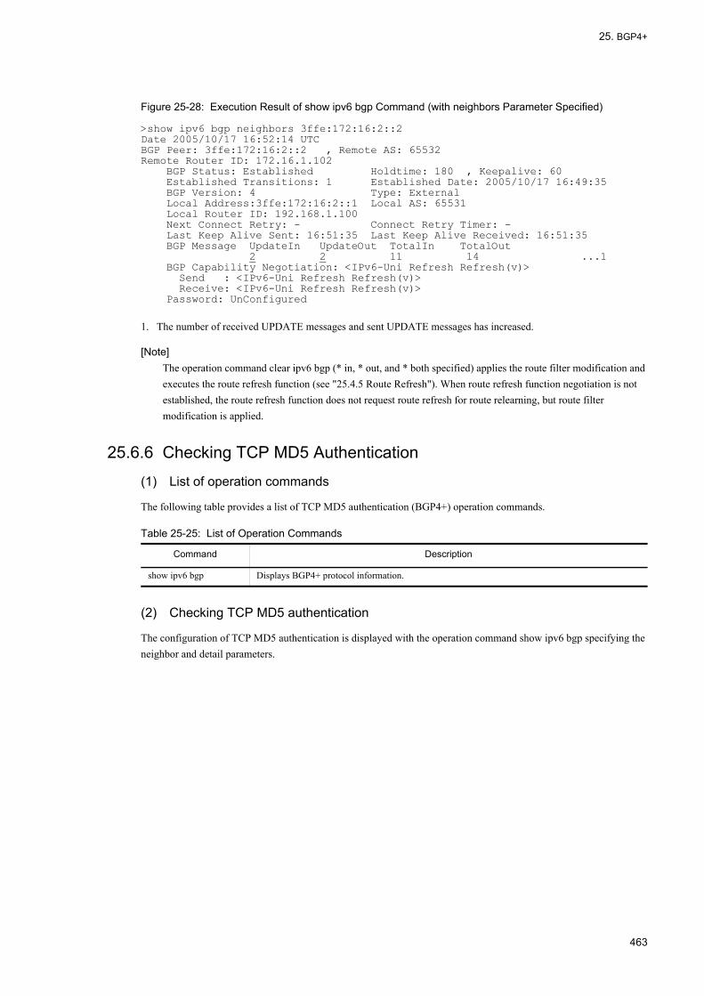
25. BGP4+
Figure 25-28: Execution Result of show ipv6 bgp Command (with neighbors Parameter Specified)
>show ipv6 bgp neighbors 3ffe:172:16:2::2Date 2005/10/17 16:52:14 UTCBGP Peer: 3ffe:172:16:2::2 , Remote AS: 65532Remote Router ID: 172.16.1.102 BGP Status: Established Holdtime: 180 , Keepalive: 60 Established Transitions: 1 Established Date: 2005/10/17 16:49:35 BGP Version: 4 Type: External Local Address:3ffe:172:16:2::1 Local AS: 65531 Local Router ID: 192.168.1.100 Next Connect Retry: - Connect Retry Timer: - Last Keep Alive Sent: 16:51:35 Last Keep Alive Received: 16:51:35 BGP Message UpdateIn UpdateOut TotalIn TotalOut 2 2 11 14 ...1 BGP Capability Negotiation: <IPv6-Uni Refresh Refresh(v)> Send : <IPv6-Uni Refresh Refresh(v)> Receive: <IPv6-Uni Refresh Refresh(v)> Password: UnConfigured
1. The number of received UPDATE messages and sent UPDATE messages has increased.
[Note]The operation command clear ipv6 bgp (* in, * out, and * both specified) applies the route filter modification and executes the route refresh function (see "25.4.5 Route Refresh"). When route refresh function negotiation is not established, the route refresh function does not request route refresh for route relearning, but route filter modification is applied.
25.6.6 Checking TCP MD5 Authentication
(1) List of operation commands
The following table provides a list of TCP MD5 authentication (BGP4+) operation commands.
Table 25-25: List of Operation Commands
(2) Checking TCP MD5 authentication
The configuration of TCP MD5 authentication is displayed with the operation command show ipv6 bgp specifying the neighbor and detail parameters.
Command Description
show ipv6 bgp Displays BGP4+ protocol information.
463

25. BGP4+
Figure 25-29: Execution Result of show ipv6 bgp Command (with neighbors detail Parameter Specified)
> show ipv6 bgp neighbor detailDate 2005/10/07 21:24:24 UTCBGP Peer: 3ffe:192:168:2::2 , Remote AS: 65531Remote Router ID: 192.168.2.100 BGP Status: Established Holdtime: 180 , Keepalive: 60 Established Transitions: 1 Established Date: 2005/10/07 21:23:48 BGP Version: 4 Type: Internal Local Address:3ffe:192:168:2::1 Local AS: 65531 Local Router ID: 192.168.1.100 Next Connect Retry: - Connect Retry Timer: - Last Keep Alive Sent: 21:23:48 Last Keep Alive Received: 21:23:48 BGP Message UpdateIn UpdateOut TotalIn TotalOut 0 0 0 3 BGP Capability Negotiation: <IPv6-Uni Refresh Refresh(v)> Send : <IPv6-Uni Refresh Refresh(v)> Receive: <IPv6-Uni Refresh Refresh(v)> Password: UnConfigured ...1 BGP Peer: 3ffe:172:16:2::2 , Remote AS: 65532Remote Router ID: 172.16.2.100 BGP Status: Established Holdtime: 180 , Keepalive: 60 Established Transitions: 1 Established Date: 2005/10/07 21:23:58 BGP Version: 4 Type: External Local Address:3ffe:172:16:2::1 Local AS: 65531 Local Router ID: 192.168.1.100 Next Connect Retry: - Connect Retry Timer: - Last Keep Alive Sent: 21:23:58 Last Keep Alive Received: 21:23:58 BGP Message UpdateIn UpdateOut TotalIn TotalOut 0 0 1 3 BGP Capability Negotiation: <IPv6-Uni Refresh Refresh(v)>> Send : <IPv6-Uni Refresh Refresh(v)> Receive: <IPv6-Uni Refresh Refresh(v)> Password : Configured ...2
1. MD5 authentication is not applied in connection with peer with peer address: 3ffe:192:168:2::2.2. MD5 authentication is applied in connection with peer with peer address: 3ffe:172:16:2::2.
[Note]Peer is not established when TCP MD5 authentication fails (BGP Status is not Established). Check the log message to determine whether TCP MD5 authentication has failed.
25.6.7 Checking BGP4+ Advertisement Route Generation
(1) List of operation commands
The following table provides a list of BGP4+ advertising route generation configuration commands.
Table 25-26: List of Operation Commands
(2) Checking BGP4+ advertisement route
(a) Displaying generated advertisement route
Use the operation command show ipv6 bgp to display the generated BGP4+ advertisement route. In this example, 3ffe:173:16::/48 and 3ffe:192:169:10::/64 are BGP4+ advertisement routes.
Command Description
show ipv6 bgp Displays BGP4+ protocol information.
show ipv6 entry Displays detailed information on specific IPv6 unicast route.
show ipv6 route Displays the route information held in the routing table.
464

25. BGP4+
Figure 25-30: Execution Result of show ipv6 bgp Command
> show ipv6 bgpDate 2005/10/20 22:43:26 UTCLocal AS: 65531, Local Router ID: 192.168.1.100Status Codes: * valid, > activeOrigin Codes: i - IGP, e - EGP, ? - incomplete Network Next Hop MED LocalPref Weight Path* 3ffe:173:16::/48 ---- - 100 0 i* 3ffe:192:169:10::/64 ---- - 100 0 i
(b) Displaying advertised route
Specify the advertised-routes parameter of the operation command show ipv6 bgp to check that the generated BGP4+ advertising route is advertised.
Figure 25-31: Execution Result of show ipv6 bgp Command (with advertised-routes Parameter Specified)
> show ipv6 bgp advertised-routes 3ffe:173:16::/48Date 2005/10/29 18:08:54 UTCBGP4+ Peer: 3ffe:172:16:2::2 , Remote AS: 65532Local AS: 65531, Local Router ID: 192.168.1.100Route 3ffe:173:16::/48* Next Hop ---- MED: -, LocalPref: -, Type: Internal route Origin: IGP Path: 65531 Next Hop Attribute: 3ffe:172:16:2::1 > show ipv6 bgp advertised-routes 3ffe:192:169:10::/64BGP4+ Peer: 3ffe:172:16:2::2 , Remote AS: 65532Local AS: 65531, Local Router ID: 192.168.1.100Route 3ffe: 3ffe:192:169:10::/64* Next Hop ---- MED: -, LocalPref: -, Type: Internal route Origin: IGP Path: 65531 Next Hop Attribute: 3ffe:172:16:2::1
25.6.8 Checking Route Flap Dampening
(1) List of operation commands
The following table provides a list of operation commands for the route flap dampening function.
Table 25-27: List of Operation Commands
(2) Checking the route flap dampening
To display the routes inhibited by the route flap dampening function, specify the "dampend-routes" parameter of the operation command show ipv6 bgp.
Command Description
show ipv6 route Displays the route information held in the routing table.
show ipv6 bgp Displays BGP4+ protocol information.
clear ipv6 bgp Releases the inhibited route and clears the route flap statistical information.
465

25. BGP4+
Figure 25-32: Execution Result of show ipv6 bgp Command (with dampend-routes Parameter Specified)
>show ipv6 bgp neighbor 3ffe:172:16:2::2 dampened-routesStatus Codes: d dampened, h history, * valid, > activeNetwork Peer Address ReUse d 3ffe:172:21:211::/64 3ffe:172:16:2::2 00:07:11 d 3ffe:172:21:212::/64 3ffe:172:16:2::2 00:19:10
To display the flap state, specify the "flap-statistics" parameter of the operation command show ipv6 bgp.
Figure 25-33: Execution Result of show ipv6 bgp Command (with flap-statistics Parameter Specified)
>show ipv6 bgp flap-statisticsStatus Codes: d dampened, h history, * valid, > active Network Peer Address Flaps Duration ReUse Penalty d 3ffe:172:21:211::/64 3ffe:172:16:2::2 114 00:12:30 00:07:11 5.0 d 3ffe:172:21:212::/64 3ffe:172:16:2::2 108 00:12:30 00:19:10 4.0 *h 3ffe:172:27:119::/64 3ffe:192:168:2::2 2 00:11:20 1.7 *h 3ffe:172:27:191::/64 3ffe:192:168:2::2 2 00:11:20 1.7 *> 3ffe:172:30:189::/64 3ffe:192:168:79:188 1 00:05:10 0.6 *> 3ffe:172:30:192::/64 3ffe:192:168:79:188 3 00:05:10 0.6>
25.6.9 Checking Route Reflection
(1) List of operation commands
The following table provides a list of operation commands for the route reflection function.
Table 25-28: List of Operation Commands
(2) Checking the route reflection
To display the route reflection clients, specify the "neighbors" and "detail" parameters of the operation command show ipv6 bgp.
Command Description
show ipv6 route Displays the route information held in the routing table.
show ipv6 bgp Displays BGP4+ protocol information.
466
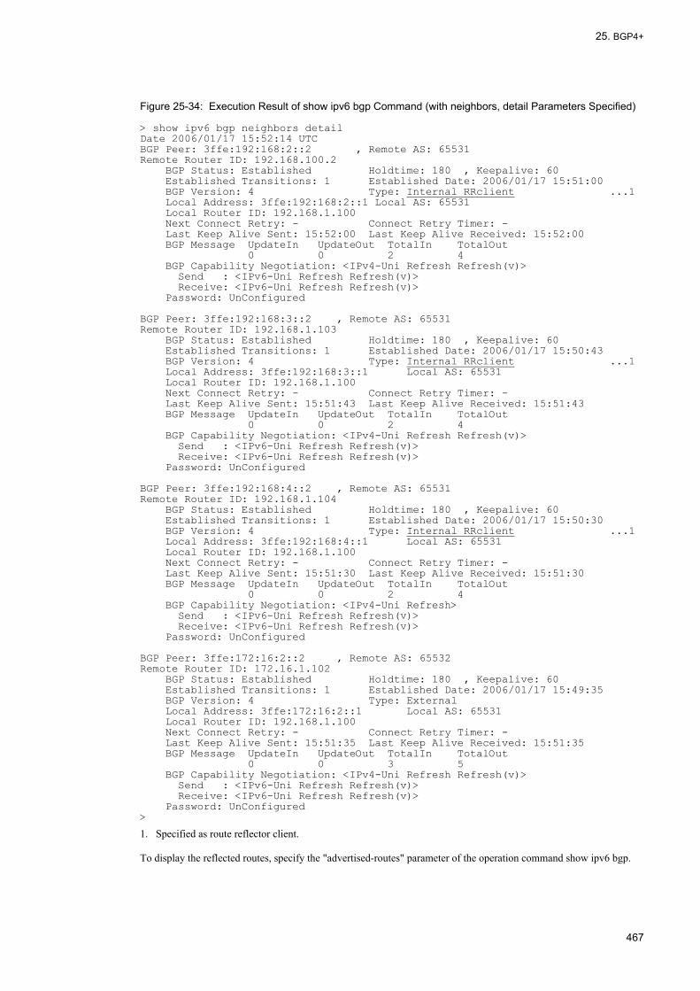
25. BGP4+
Figure 25-34: Execution Result of show ipv6 bgp Command (with neighbors, detail Parameters Specified)
> show ipv6 bgp neighbors detailDate 2006/01/17 15:52:14 UTCBGP Peer: 3ffe:192:168:2::2 , Remote AS: 65531Remote Router ID: 192.168.100.2 BGP Status: Established Holdtime: 180 , Keepalive: 60 Established Transitions: 1 Established Date: 2006/01/17 15:51:00 BGP Version: 4 Type: Internal RRclient ...1 Local Address: 3ffe:192:168:2::1 Local AS: 65531 Local Router ID: 192.168.1.100 Next Connect Retry: - Connect Retry Timer: - Last Keep Alive Sent: 15:52:00 Last Keep Alive Received: 15:52:00 BGP Message UpdateIn UpdateOut TotalIn TotalOut 0 0 2 4 BGP Capability Negotiation: <IPv4-Uni Refresh Refresh(v)> Send : <IPv6-Uni Refresh Refresh(v)> Receive: <IPv6-Uni Refresh Refresh(v)> Password: UnConfigured BGP Peer: 3ffe:192:168:3::2 , Remote AS: 65531Remote Router ID: 192.168.1.103 BGP Status: Established Holdtime: 180 , Keepalive: 60 Established Transitions: 1 Established Date: 2006/01/17 15:50:43 BGP Version: 4 Type: Internal RRclient ...1 Local Address: 3ffe:192:168:3::1 Local AS: 65531 Local Router ID: 192.168.1.100 Next Connect Retry: - Connect Retry Timer: - Last Keep Alive Sent: 15:51:43 Last Keep Alive Received: 15:51:43 BGP Message UpdateIn UpdateOut TotalIn TotalOut 0 0 2 4 BGP Capability Negotiation: <IPv4-Uni Refresh Refresh(v)> Send : <IPv6-Uni Refresh Refresh(v)> Receive: <IPv6-Uni Refresh Refresh(v)> Password: UnConfigured BGP Peer: 3ffe:192:168:4::2 , Remote AS: 65531Remote Router ID: 192.168.1.104 BGP Status: Established Holdtime: 180 , Keepalive: 60 Established Transitions: 1 Established Date: 2006/01/17 15:50:30 BGP Version: 4 Type: Internal RRclient ...1 Local Address: 3ffe:192:168:4::1 Local AS: 65531 Local Router ID: 192.168.1.100 Next Connect Retry: - Connect Retry Timer: - Last Keep Alive Sent: 15:51:30 Last Keep Alive Received: 15:51:30 BGP Message UpdateIn UpdateOut TotalIn TotalOut 0 0 2 4 BGP Capability Negotiation: <IPv4-Uni Refresh> Send : <IPv6-Uni Refresh Refresh(v)> Receive: <IPv6-Uni Refresh Refresh(v)> Password: UnConfigured BGP Peer: 3ffe:172:16:2::2 , Remote AS: 65532Remote Router ID: 172.16.1.102 BGP Status: Established Holdtime: 180 , Keepalive: 60 Established Transitions: 1 Established Date: 2006/01/17 15:49:35 BGP Version: 4 Type: External Local Address: 3ffe:172:16:2::1 Local AS: 65531 Local Router ID: 192.168.1.100 Next Connect Retry: - Connect Retry Timer: - Last Keep Alive Sent: 15:51:35 Last Keep Alive Received: 15:51:35 BGP Message UpdateIn UpdateOut TotalIn TotalOut 0 0 3 5 BGP Capability Negotiation: <IPv4-Uni Refresh Refresh(v)> Send : <IPv6-Uni Refresh Refresh(v)> Receive: <IPv6-Uni Refresh Refresh(v)> Password: UnConfigured>
1. Specified as route reflector client.
To display the reflected routes, specify the "advertised-routes" parameter of the operation command show ipv6 bgp.
467

25. BGP4+
Figure 25-35: Execution Result of show ipv6 bgp Command (with advertised-routes Parameter Specified)
> show ipv6 bgp advertised-routesDate 2006/01/18 22:44:54 UTCBGP Peer: 3ffe:192:168:3::2 , Remote AS: 65531Local AS: 65531, Local Router ID: 192.168.1.100Origin Codes: i - IGP, e - EGP, ? - incompleteNetwork Next Hop MED LocalPref Path3ffe:192:169:10::/64 3ffe:192:168:2::2 120 100 i3ffe:192:169:20::/64 3ffe:192:168:2::2 100 100 iBGP Peer: 3ffe:192:168:4::2 , Remote AS: 65531Local AS: 65531, Local Router ID: 192.168.1.100Origin Codes: i - IGP, e - EGP, ? - incompleteNetwork Next Hop MED LocalPref Path3ffe:192:169:10::/64 3ffe:192:168:2::2 120 100 i3ffe:192:169:20::/64 3ffe:192:168:2::2 100 100 i
25.6.10 Checking Confederation
(1) List of operation commands
The following table provides a list of operation commands for the confederation function.
Table 25-29: List of Operation Commands
(2) Checking the confederation
To display the confederation configuration, specify the "neighbors" and "detail" parameters of the operation command show ipv6 bgp.
Command Description
show ipv6 route Displays the route information held in the routing table.
show ipv6 bgp Displays BGP4+ protocol information.
468

25. BGP4+
Figure 25-36: Execution Result of show ipv6 bgp Command (with neighbors, detail Parameters Specified)
> show ipv6 bgp neighbors detailDate 2006/01/17 15:52:14 UTCBGP Peer: 3ffe:192:168:2::2 , Remote AS: 64512 ...2Remote Router ID: 192.168.100.2 BGP Status: Established Holdtime: 180 , Keepalive: 60 Established Transitions: 1 Established Date: 2006/01/17 15:51:00 BGP Version: 4 Type: Internal Local Address: 3ffe:192:168:2::1 Local AS: 64512 Local Router ID: 192.168.1.100 Next Connect Retry: - Connect Retry Timer: - Last Keep Alive Sent: 15:52:00 Last Keep Alive Received: 15:52:00 BGP Message UpdateIn UpdateOut TotalIn TotalOut 0 0 2 4 BGP Capability Negotiation: <IPv6-Uni Refresh Refresh(v)> Send : <IPv6-Uni Refresh Refresh(v)> Receive: <IPv6-Uni Refresh Refresh(v)> Password: UnConfigured Confederation ID: 65531, Member AS: 64512 ...1BGP Peer: 3ffe:192:168:4::2 , Remote AS: 64513 ...2Remote Router ID: 192.168.1.104 BGP Status: Established Holdtime: 180 , Keepalive: 60 Established Transitions: 1 Established Date: 2006/01/17 15:50:30 BGP Version: 4 Type: ConfedExt ...3 Local Address: 3ffe:192:168:4::1 Local AS: 64512 Local Router ID: 192.168.1.100 Next Connect Retry: - Connect Retry Timer: - Last Keep Alive Sent: 15:51:30 Last Keep Alive Received: 15:51:30 BGP Message UpdateIn UpdateOut TotalIn TotalOut 0 0 2 4 BGP Capability Negotiation: <IPv6-Uni Refresh> Send : <IPv6-Uni Refresh Refresh(v)> Receive: <IPv6-Uni Refresh Refresh(v)> Password: UnConfigured Confederation ID: 65531, Member AS: 64512 ...1BGP Peer: 3ffe:192:168:5::2 , Remote AS: 64514 ...2Remote Router ID: 192.168.1.104 BGP Status: Established Holdtime: 180 , Keepalive: 60 Established Transitions: 1 Established Date: 2006/01/17 15:50:30 BGP Version: 4 Type: ConfedExt ...3 Local Address: 3ffe:192:168:5::1 Local AS: 64512 Local Router ID: 192.168.1.100 Next Connect Retry: - Connect Retry Timer: - Last Keep Alive Sent: 15:51:30 Last Keep Alive Received: 15:51:30 BGP Message UpdateIn UpdateOut TotalIn TotalOut 0 0 2 4 BGP Capability Negotiation: <IPv6-Uni Refresh> Send : <IPv6-Uni Refresh Refresh(v)> Receive: <IPv6-Uni Refresh Refresh(v)> Password: UnConfigured BGP Peer: 3ffe:172:16:2::2 , Remote AS: 65532Remote Router ID: 172.16.1.102 BGP Status: Established Holdtime: 180 , Keepalive: 60 Established Transitions: 1 Established Date: 2006/01/17 15:49:35 BGP Version: 4 Type: External Local Address: 3ffe:172:16:2::1 Local AS: 65531 Local Router ID: 192.168.1.100 Next Connect Retry: - Connect Retry Timer: - Last Keep Alive Sent: 15:51:35 Last Keep Alive Received: 15:51:35 BGP Message UpdateIn UpdateOut TotalIn TotalOut 0 0 3 5 BGP Capability Negotiation: <IPv6-Uni Refresh Refresh(v)> Send : <IPv6-Uni Refresh Refresh(v)> Receive: <IPv6-Uni Refresh Refresh(v)> Password: UnConfigured>
1. The local router belongs to the confederation member AS.2. Displays the member AS number to connect.3. The type of destination peer is member AS peer.
469
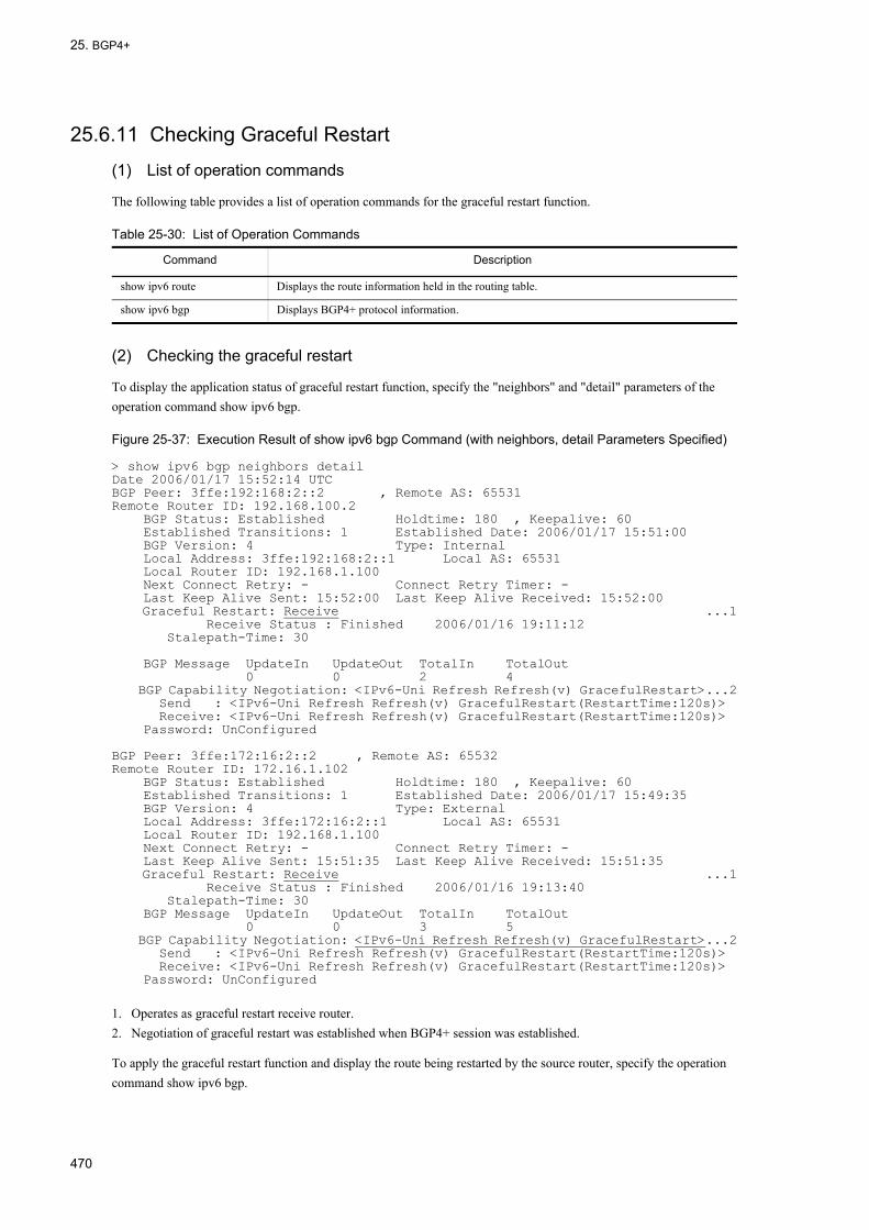
25. BGP4+
25.6.11 Checking Graceful Restart
(1) List of operation commands
The following table provides a list of operation commands for the graceful restart function.
Table 25-30: List of Operation Commands
(2) Checking the graceful restart
To display the application status of graceful restart function, specify the "neighbors" and "detail" parameters of the operation command show ipv6 bgp.
Figure 25-37: Execution Result of show ipv6 bgp Command (with neighbors, detail Parameters Specified)
> show ipv6 bgp neighbors detailDate 2006/01/17 15:52:14 UTCBGP Peer: 3ffe:192:168:2::2 , Remote AS: 65531Remote Router ID: 192.168.100.2 BGP Status: Established Holdtime: 180 , Keepalive: 60 Established Transitions: 1 Established Date: 2006/01/17 15:51:00 BGP Version: 4 Type: Internal Local Address: 3ffe:192:168:2::1 Local AS: 65531 Local Router ID: 192.168.1.100 Next Connect Retry: - Connect Retry Timer: - Last Keep Alive Sent: 15:52:00 Last Keep Alive Received: 15:52:00 Graceful Restart: Receive ...1 Receive Status : Finished 2006/01/16 19:11:12 Stalepath-Time: 30 BGP Message UpdateIn UpdateOut TotalIn TotalOut 0 0 2 4 BGP Capability Negotiation: <IPv6-Uni Refresh Refresh(v) GracefulRestart>...2 Send : <IPv6-Uni Refresh Refresh(v) GracefulRestart(RestartTime:120s)> Receive: <IPv6-Uni Refresh Refresh(v) GracefulRestart(RestartTime:120s)> Password: UnConfigured BGP Peer: 3ffe:172:16:2::2 , Remote AS: 65532Remote Router ID: 172.16.1.102 BGP Status: Established Holdtime: 180 , Keepalive: 60 Established Transitions: 1 Established Date: 2006/01/17 15:49:35 BGP Version: 4 Type: External Local Address: 3ffe:172:16:2::1 Local AS: 65531 Local Router ID: 192.168.1.100 Next Connect Retry: - Connect Retry Timer: - Last Keep Alive Sent: 15:51:35 Last Keep Alive Received: 15:51:35 Graceful Restart: Receive ...1 Receive Status : Finished 2006/01/16 19:13:40 Stalepath-Time: 30 BGP Message UpdateIn UpdateOut TotalIn TotalOut 0 0 3 5 BGP Capability Negotiation: <IPv6-Uni Refresh Refresh(v) GracefulRestart>...2 Send : <IPv6-Uni Refresh Refresh(v) GracefulRestart(RestartTime:120s)> Receive: <IPv6-Uni Refresh Refresh(v) GracefulRestart(RestartTime:120s)> Password: UnConfigured
1. Operates as graceful restart receive router.2. Negotiation of graceful restart was established when BGP4+ session was established.
To apply the graceful restart function and display the route being restarted by the source router, specify the operation command show ipv6 bgp.
Command Description
show ipv6 route Displays the route information held in the routing table.
show ipv6 bgp Displays BGP4+ protocol information.
470

25. BGP4+
Figure 25-38: Execution Result of show ipv6 bgp Command
> show ipv6 bgpDate 2006/01/16 19:12:23 UTCLocal AS: 65531, Local Router ID: 192.168.1.100Status Codes: * valid, > active , S StaleOrigin Codes: i - IGP, e - EGP, ? - incomplete Network Next Hop MED LocalPref Weight PathS 3ffe:10:10::/48 3ffe:172:16:2::2 - 120 20 65532 65528 i ...1S 3ffe:10:20::/48 3ffe:172:16:2::2 - 80 20 65532 65528 i ...1*> 3ffe:172:20::/48 3ffe:192:168:2::2 - 100 10 65530 i* 3ffe:172:30::/48 3ffe:192:168:2::2 100 100 10 65530 i* 3ffe:192:168:10::/64 3ffe:192:168:2::2 - 100 10 65530 i*> 3ffe:192:169:10::/64 3ffe:192:168:2::2 - 100 10 i*> 3ffe:192:169:20::/64 3ffe:192:168:2::2 - 100 10 i
1. Indicates the route being restarted by the source router.
25.6.12 Checking BGP4+ Learned Route Restriction
(1) List of operation commands
The following table provides a list of operation commands for the restriction on the number of BGP4+ learned routes.
Table 25-31: List of Operation Commands
(2) Checking the restriction on the number of BGP4+ learned routes and the routes learned from the peer
To check the restriction on the number of BGP4+ learned routes and the number of routes learned from the peer (total of active routes and inactive routes), specify the "neighbors" parameter along with <As>, <Peer Address>, <Host name> or "detail" parameter of the operation command show ipv6 bgp.
Command Description
show ipv6 route Displays the route information held in the routing table.
show ipv6 bgp Displays BGP4+ protocol information.
clear ipv6 bgp Reconnects the peer disconnected by the restriction on the number of BGP4+ learned routes.
471

25. BGP4+
Figure 25-39: Execution Result of show ipv6 bgp Command (with neighbors, detail Parameters Specified)
> show ipv6 bgp neighbors detail Date 2006/01/13 18:45:09 BGP Peer: 3ffe:172:16:2::2, Remote AS: 65532 Remote Router ID: 172.16.2.200 BGP Status: Idle HoldTime: 90 Established Transitions: 1 Established Date: 2006/01/13 18:42:26...1 BGP Version: 4 Type: External Local Address: 3ffe:172:16:23::214, Local AS: 65531 Local Router ID: 172.16.2.100 Next Connect Retry: 00:32, Connect Retry Timer: 00:32 Last Keep Alive Sent: 18:42:20, Last Keep Alive Received: 18:42:20 NLRI of End-of-RIB Marker: Advertised and Received BGP Message UpdateIn UpdateOut TotalIn TotalOut 12 14 36 42 BGP Peer Last Error: Cease(Over Prefix Limit) ...2 BGP Routes Accepted MaximumPrefix RestartTime Threshold ...3 0 1000 60m 80% BGP Capability Negotiation: <IPv6-Uni> Send : <IPv6-Uni> Receive: <IPv6-Uni> Password : Configured BGP Peer: 3ffe:192:168:2::1, Remote AS: 65531 Remote Router ID: 192.168.2.200 BGP Status:Active HoldTime: 90 Established Transitions: 1 Established Date: 2006/01/13 18:42:31 BGP Version: 4 Type: Internal Local Address: 3ffe:192:168:23::214, Local AS: 65531 Local Router ID: 192.168.2.100 Next Connect Retry: 00:32, Connect Retry Timer: 00:32 Last Keep Alive Sent: 18:44:31, Last Keep Alive Received: 18:44:31 NLRI of End-of-RIB Marker: Advertised and Received BGP Message UpdateIn UpdateOut TotalIn TotalOut 12 14 36 42 BGP Routes Accepted MaximumPrefix RestartTime Threshold ...4 94 1000 none 75% BGP Capability Negotiation: <IPv6-Uni> Send : <IPv6-Uni> Receive: <IPv6-Uni> Password : Configured
1. The peer was disconnected at 2006/01/13 18:42:26.2. Peer is disconnected due to the restriction on the number of learned routes.3. Disconnected peer is reconnected after 60 minutes.4. For the upper limit of 1000 for the number of routes to be learned from the peer, 94 routes are currently learned.
(3) Reconnecting the BGP4+ session disconnected due to the restriction on the number of BGP4+ learned routes
To reconnect the disconnected BGP4+ session exceeding the upper limit of BGP4+ learned routes, specify the operation command clear ipv6 bgp* or the <Peer Address> and <Host Name> parameters.
[Reconnection of BGP4+ session by command]
1. #clear ipv6 bgp 3ffe:172:16:2::2
Reconnect the BGP4+ session with remote address 3ffe:172:16:2::2 which was disconnected due to the restriction on the number of BGP4+ learned routes.
472

26. Route Filtering (IPv6)
26Route Filtering (IPv6)This chapter provides a description of route filtering (IPv6).
26.1 Route Filtering Overview
26.2 Configuration
26.3 Operation
473

26. Route Filtering (IPv6)
26.1 Route Filtering Overview
26.1.1 Outline of Route FilteringRoute filtering is a function to control routes by filtering. There are two types of route filtering: learned route filtering and route advertisement filtering. The route filtering concept is shown in the figure below.
Figure 26-1: Conceptual Diagram of Route Filtering
(1) Learned route filtering
Learned route filtering filters the route learned by protocol between the protocol and routing table. This function can be used to control whether to enable learned routes and change route attributes.
If learned route filtering is not configured, all learned routes are valid routes.
(2) Route advertisement filtering
Route advertisement filtering filters routes in the routing table between the routing table and protocol. This function can be used to control whether to advertise routes and change advertised route information.
If route advertisement filtering is not configured, only routes satisfying predetermined condition are advertised for each protocol.
474
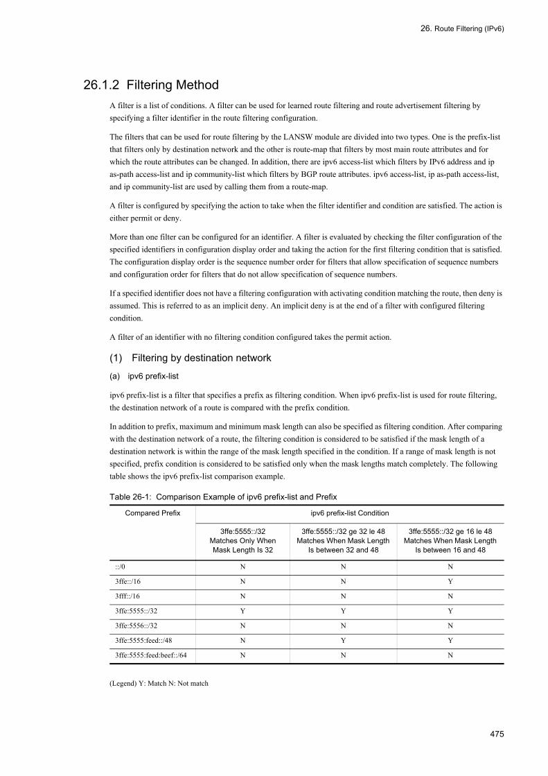
26. Route Filtering (IPv6)
26.1.2 Filtering MethodA filter is a list of conditions. A filter can be used for learned route filtering and route advertisement filtering by specifying a filter identifier in the route filtering configuration.
The filters that can be used for route filtering by the LANSW module are divided into two types. One is the prefix-list that filters only by destination network and the other is route-map that filters by most main route attributes and for which the route attributes can be changed. In addition, there are ipv6 access-list which filters by IPv6 address and ip as-path access-list and ip community-list which filters by BGP route attributes. ipv6 access-list, ip as-path access-list, and ip community-list are used by calling them from a route-map.
A filter is configured by specifying the action to take when the filter identifier and condition are satisfied. The action is either permit or deny.
More than one filter can be configured for an identifier. A filter is evaluated by checking the filter configuration of the specified identifiers in configuration display order and taking the action for the first filtering condition that is satisfied. The configuration display order is the sequence number order for filters that allow specification of sequence numbers and configuration order for filters that do not allow specification of sequence numbers.
If a specified identifier does not have a filtering configuration with activating condition matching the route, then deny is assumed. This is referred to as an implicit deny. An implicit deny is at the end of a filter with configured filtering condition.
A filter of an identifier with no filtering condition configured takes the permit action.
(1) Filtering by destination network
(a) ipv6 prefix-list
ipv6 prefix-list is a filter that specifies a prefix as filtering condition. When ipv6 prefix-list is used for route filtering, the destination network of a route is compared with the prefix condition.
In addition to prefix, maximum and minimum mask length can also be specified as filtering condition. After comparing with the destination network of a route, the filtering condition is considered to be satisfied if the mask length of a destination network is within the range of the mask length specified in the condition. If a range of mask length is not specified, prefix condition is considered to be satisfied only when the mask lengths match completely. The following table shows the ipv6 prefix-list comparison example.
Table 26-1: Comparison Example of ipv6 prefix-list and Prefix
(Legend) Y: Match N: Not match
Compared Prefix ipv6 prefix-list Condition
3ffe:5555::/32Matches Only When Mask Length Is 32
3ffe:5555::/32 ge 32 le 48Matches When Mask Length
Is between 32 and 48
3ffe:5555::/32 ge 16 le 48Matches When Mask Length
Is between 16 and 48
::/0 N N N
3ffe::/16 N N Y
3fff::/16 N N N
3ffe:5555::/32 Y Y Y
3ffe:5556::/32 N N N
3ffe:5555:feed::/48 N Y Y
3ffe:5555:feed:beef::/64 N N N
475
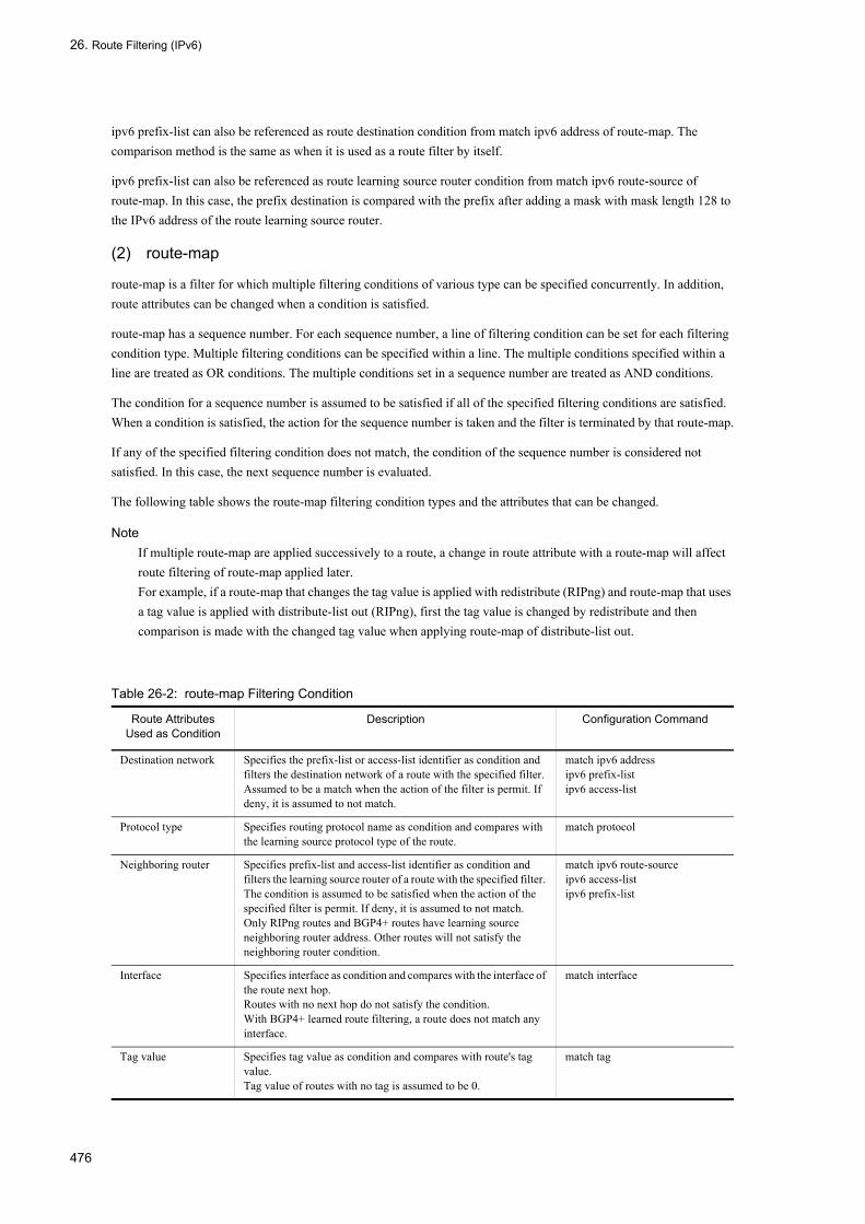
26. Route Filtering (IPv6)
ipv6 prefix-list can also be referenced as route destination condition from match ipv6 address of route-map. The comparison method is the same as when it is used as a route filter by itself.
ipv6 prefix-list can also be referenced as route learning source router condition from match ipv6 route-source of route-map. In this case, the prefix destination is compared with the prefix after adding a mask with mask length 128 to the IPv6 address of the route learning source router.
(2) route-map
route-map is a filter for which multiple filtering conditions of various type can be specified concurrently. In addition, route attributes can be changed when a condition is satisfied.
route-map has a sequence number. For each sequence number, a line of filtering condition can be set for each filtering condition type. Multiple filtering conditions can be specified within a line. The multiple conditions specified within a line are treated as OR conditions. The multiple conditions set in a sequence number are treated as AND conditions.
The condition for a sequence number is assumed to be satisfied if all of the specified filtering conditions are satisfied. When a condition is satisfied, the action for the sequence number is taken and the filter is terminated by that route-map.
If any of the specified filtering condition does not match, the condition of the sequence number is considered not satisfied. In this case, the next sequence number is evaluated.
The following table shows the route-map filtering condition types and the attributes that can be changed.
NoteIf multiple route-map are applied successively to a route, a change in route attribute with a route-map will affect route filtering of route-map applied later.For example, if a route-map that changes the tag value is applied with redistribute (RIPng) and route-map that uses a tag value is applied with distribute-list out (RIPng), first the tag value is changed by redistribute and then comparison is made with the changed tag value when applying route-map of distribute-list out.
Table 26-2: route-map Filtering Condition
Route Attributes Used as Condition
Description Configuration Command
Destination network Specifies the prefix-list or access-list identifier as condition and filters the destination network of a route with the specified filter. Assumed to be a match when the action of the filter is permit. If deny, it is assumed to not match.
match ipv6 addressipv6 prefix-listipv6 access-list
Protocol type Specifies routing protocol name as condition and compares with the learning source protocol type of the route.
match protocol
Neighboring router Specifies prefix-list and access-list identifier as condition and filters the learning source router of a route with the specified filter. The condition is assumed to be satisfied when the action of the specified filter is permit. If deny, it is assumed to not match.Only RIPng routes and BGP4+ routes have learning source neighboring router address. Other routes will not satisfy the neighboring router condition.
match ipv6 route-sourceipv6 access-listipv6 prefix-list
Interface Specifies interface as condition and compares with the interface of the route next hop.Routes with no next hop do not satisfy the condition.With BGP4+ learned route filtering, a route does not match any interface.
match interface
Tag value Specifies tag value as condition and compares with route's tag value.Tag value of routes with no tag is assumed to be 0.
match tag
476
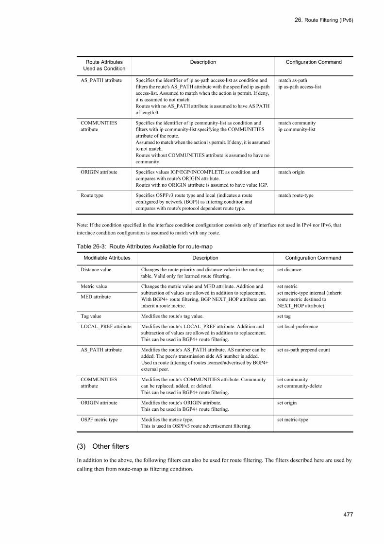
26. Route Filtering (IPv6)
Note: If the condition specified in the interface condition configuration consists only of interface not used in IPv4 nor IPv6, that interface condition configuration is assumed to match with any route.
Table 26-3: Route Attributes Available for route-map
(3) Other filters
In addition to the above, the following filters can also be used for route filtering. The filters described here are used by calling then from route-map as filtering condition.
AS_PATH attribute Specifies the identifier of ip as-path access-list as condition and filters the route's AS_PATH attribute with the specified ip as-path access-list. Assumed to match when the action is permit. If deny, it is assumed to not match.Routes with no AS_PATH attribute is assumed to have AS PATH of length 0.
match as-pathip as-path access-list
COMMUNITIES attribute
Specifies the identifier of ip community-list as condition and filters with ip community-list specifying the COMMUNITIES attribute of the route.Assumed to match when the action is permit. If deny, it is assumed to not match.Routes without COMMUNITIES attribute is assumed to have no community.
match communityip community-list
ORIGIN attribute Specifies values IGP/EGP/INCOMPLETE as condition and compares with route's ORIGIN attribute.Routes with no ORIGIN attribute is assumed to have value IGP.
match origin
Route type Specifies OSPFv3 route type and local (indicates a route configured by network (BGP)) as filtering condition and compares with route's protocol dependent route type.
match route-type
Modifiable Attributes Description Configuration Command
Distance value Changes the route priority and distance value in the routing table. Valid only for learned route filtering.
set distance
Metric value Changes the metric value and MED attribute. Addition and subtraction of values are allowed in addition to replacement.With BGP4+ route filtering, BGP NEXT_HOP attribute can inherit a route metric.
set metricset metric-type internal (inherit route metric destined to NEXT_HOP attribute)
MED attribute
Tag value Modifies the route's tag value. set tag
LOCAL_PREF attribute Modifies the route's LOCAL_PREF attribute. Addition and subtraction of values are allowed in addition to replacement.This can be used in BGP4+ route filtering.
set local-preference
AS_PATH attribute Modifies the route's AS_PATH attribute. AS number can be added. The peer's transmission side AS number is added.Used in route filtering of routes learned/advertised by BGP4+ external peer.
set as-path prepend count
COMMUNITIES attribute
Modifies the route's COMMUNITIES attribute. Community can be replaced, added, or deleted.This can be used in BGP4+ route filtering.
set communityset community-delete
ORIGIN attribute Modifies the route's ORIGIN attribute.This can be used in BGP4+ route filtering.
set origin
OSPF metric type Modifies the metric type.This is used in OSPFv3 route advertisement filtering.
set metric-type
Route Attributes Used as Condition
Description Configuration Command
477
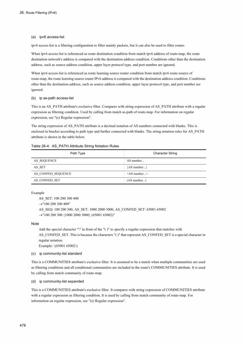
26. Route Filtering (IPv6)
(a) ipv6 access-list
ipv6 access-list is a filtering configuration to filter mainly packets, but it can also be used to filter routes.
When ipv6 access-list is referenced as route destination condition from match ipv6 address of route-map, the route destination network's address is compared with the destination address condition. Conditions other than the destination address, such as source address condition, upper layer protocol type, and port number are ignored.
When ipv6 access-list is referenced as route learning source router condition from match ipv6 route-source of route-map, the route learning source router IPv6 address is compared with the destination address condition. Conditions other than the destination address, such as source address condition, upper layer protocol type, and port number are ignored.
(b) ip as-path access-list
This is an AS_PATH attribute's exclusive filter. Compares with string expression of AS_PATH attribute with a regular expression as filtering condition. Used by calling from match as-path of route-map. For information on regular expression, see "(e) Regular expression".
The string expression of AS_PATH attribute is a decimal notation of AS numbers connected with blanks. This is enclosed in bracket according to path type and further connected with blanks. The string notation rules for AS_PATH attribute is shown in the table below.
Table 26-4: AS_PATH Attribute String Notation Rules
ExampleAS_SET: 100 200 300 400→"100 200 300 400"AS_SEQ: 100 200 300, AS_SET: 1000 2000 3000, AS_CONFED_SET: 65001 65002→"100 200 300 {1000 2000 3000} (65001 65002)"
NoteAdd the special character "\" in front of the "( )" to specify a regular expression that matches with AS_CONFED_SET. This is because the characters "( )" that represent AS_CONFED_SET is a special character in regular notation.Example: \(65001 65002\)
(c) ip community-list standard
This is a COMMUNITIES attribute's exclusive filter. It is assumed to be a match when multiple communities are used as filtering conditions and all conditional communities are included in the route's COMMUNITIES attribute. It is used by calling from match community of route-map.
(d) ip community-list expanded
This is a COMMUNITIES attribute's exclusive filter. It compares with string expression of COMMUNITIES attribute with a regular expression as filtering condition. It is used by calling from match community of route-map. For information on regular expression, see "(e) Regular expression".
Path Type Character String
AS_SEQUENCE AS number...
AS_SET {AS number...}
AS_CONFED_SEQUENCE <AS number...>
AS_CONFED_SET (AS number...)
478

26. Route Filtering (IPv6)
The regular expression of COMMUNITIES attribute consists of community value converted to string and connected with blank starting with the one with the smallest value. The following table shows the string notation rules for community value.
Table 26-5: COMMUNITIES Attribute String Notation
(e) Regular expression
A regular expression is a method of describing a character pattern. Patterns such as repeating strings can be written using a regular expression. Regular expressions are used to specify filtering conditions for AS_PATH attribute and COMMUNITIES attribute.
Characters allowed in a regular expression are: normal characters such as numerals, lowercase alphabets, uppercase alphabets, and symbols (excluding double quotation), and special characters. Special character combined with normal character "\" matches with the same character in the string. Each special character represents a pattern. The following table shows the special characters and their pattern.
Table 26-6: Special Character and Its Pattern
The following table shows the connecting priority of characters used in a regular expression.
Community Value Character String
0xFFFFFF01 (hexadecimal) no-export
0xFFFFFF02 (hexadecimal) no-advertise
0xFFFFFF03 (hexadecimal) local-AS
Other than the above <AS number>:<Lower 2 octets><AS number> and <Lower 2 octets> are both decimal notations
Special Character
Pattern
. Indicates all single characters including a blank.
* Indicates that a character or character set is repeated 0 or more times.
+ Indicates that a character or character set is repeated 1 or more times.
? Indicates that the previous character or character set is repeated 0 or 1 time (press [Ctrl] + [V] and then enter [?] during command entry).
^ Indicates the beginning of a character string.
$ Indicates the end of a character string.
_ Indicates the beginning of a character string, the end of a character string, " " (blank), "_", ",", "(" (normal character), ")" (normal character), "{", "}", "<", or ">".
[ ] Indicates the single character in the character range [ ]. Characters other than the following are treated as normal characters within [ ] (does not function as special character).^: Negates the pattern when placed at the beginning of [ ] indicating a range of characters.-: Used to indicate the beginning and end of the range in [ ]. Specify so that the character code of character preceding"-" is smaller than the character code of the character following "-".See "Configuration Commands, Vol. 1, Table 1-3: List of Character Code" for the character code.Example: [6-8] indicates one of the characters 6, 7, or 8. [^6-8] indicates any character other than 6, 7, or 8.
( ) Indicates the set of multiple characters. Up to nine sets can be nested.
| Indicates an OR condition.
\ When this is placed before a special character described above, it is treated as a normal character.
479

26. Route Filtering (IPv6)
Table 26-7: Concatenation Priority of Characters Used in Regular Expression
When using a regular expression in a configuration command or operation command, enclose them in double quotation marks (").
Example 1> show ipv6 bgp aspath-regexp "^$"
Example 2(config)# ip as-path access-list 10 permit "_100_"
26.1.3 RIPng
(1) RIPng learned route filtering
With RIPng, all learned routes can be filtered. Routes not learned as the result of filtering are not entered in the routing table.
(a) Filter application method and application sequence
Learned routes are filtered with filter configured with distribute-list in. A filter can be applied to routes learned from a specific interface only by specifying the interface with a parameter. The following table shows the RIPng learned route filtering configuration commands.
After a route is learned, apply the specified filter in the order shown in the table. If there is no filter to apply or if the results of applying a filter is all permit, the learned route is entered in the routing table as valid route. If there is any filter where the applied result is deny, that learned route is not entered in the routing table.
Table 26-8: Configuration Commands of RIPng Learned Route Filtering
(b) Route attributes available for learned route filtering
The following table shows attributes that can be modified by RIPng learned route filtering.
The modified metric value is used in RIPng priority route selection. The modified distance value is used in priority route selection among routing types.
Table 26-9: Route Attributes Available for RIPng Learned Route Filtering
Precedence Character
High↑
↓Low
( )
* + ?
Normal character ., [ ], ^, $
|
Command Parameter Filtered Route
distribute-list in (RIPng) <Interface> Applies filter only to RIPng route learned from the specified IPv6 interface.
None Applies filter to all learned RIPng routes.
Attribute Default Value
Distance value Value specified for distance (RIPng).120 when this value is not specified.
480
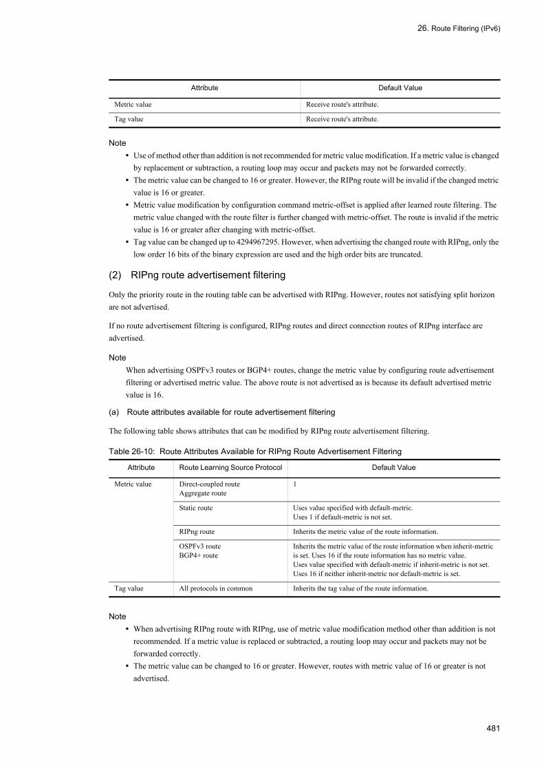
26. Route Filtering (IPv6)
Note• Use of method other than addition is not recommended for metric value modification. If a metric value is changed
by replacement or subtraction, a routing loop may occur and packets may not be forwarded correctly.• The metric value can be changed to 16 or greater. However, the RIPng route will be invalid if the changed metric
value is 16 or greater.• Metric value modification by configuration command metric-offset is applied after learned route filtering. The
metric value changed with the route filter is further changed with metric-offset. The route is invalid if the metric value is 16 or greater after changing with metric-offset.
• Tag value can be changed up to 4294967295. However, when advertising the changed route with RIPng, only the low order 16 bits of the binary expression are used and the high order bits are truncated.
(2) RIPng route advertisement filtering
Only the priority route in the routing table can be advertised with RIPng. However, routes not satisfying split horizon are not advertised.
If no route advertisement filtering is configured, RIPng routes and direct connection routes of RIPng interface are advertised.
NoteWhen advertising OSPFv3 routes or BGP4+ routes, change the metric value by configuring route advertisement filtering or advertised metric value. The above route is not advertised as is because its default advertised metric value is 16.
(a) Route attributes available for route advertisement filtering
The following table shows attributes that can be modified by RIPng route advertisement filtering.
Table 26-10: Route Attributes Available for RIPng Route Advertisement Filtering
Note• When advertising RIPng route with RIPng, use of metric value modification method other than addition is not
recommended. If a metric value is replaced or subtracted, a routing loop may occur and packets may not be forwarded correctly.
• The metric value can be changed to 16 or greater. However, routes with metric value of 16 or greater is not advertised.
Metric value Receive route's attribute.
Tag value Receive route's attribute.
Attribute Route Learning Source Protocol Default Value
Metric value Direct-coupled routeAggregate route
1
Static route Uses value specified with default-metric.Uses 1 if default-metric is not set.
RIPng route Inherits the metric value of the route information.
OSPFv3 routeBGP4+ route
Inherits the metric value of the route information when inherit-metric is set. Uses 16 if the route information has no metric value.Uses value specified with default-metric if inherit-metric is not set.Uses 16 if neither inherit-metric nor default-metric is set.
Tag value All protocols in common Inherits the tag value of the route information.
Attribute Default Value
481

26. Route Filtering (IPv6)
• Metric value modification by configuration command metric-offset is applied after route advertisement filtering. The metric value changed with the route filter is further changed with metric-offset. The route is not advertised if the metric value is 16 or greater after changing with metric-offset.
• If the tag value is changed to value greater than 65535, only the low order 16 bits of the binary expression are used and the high order bits are truncated.
(3) Filter application method and application sequence
Route advertisement filtering is divided into three steps.
1. First, select the route to be advertised with RIPng. Specify the learning source protocol of the route that needs to be advertised. Use the configuration command redistribute to specify the protocol. Specify a conditional route type with redistribute, to advertise only specified type of routes. Also, specify route-map to advertise only routes that are permitted as the result of filtering with route-map. redistribute uses the route attribute in the routing table to compare the condition.The direct connection routes of RIPng route and RIPng interface are advertised without specifying redistribute.The attributes of the advertised route can be changed by directly specifying the route-map that changes the route attribute and route attributes in redistribute.
2. Set the metric value to the default value determined by protocol. However, if the metric value is changed with redistribute, use the value changed with redistribute.See "Table 26-10: Route Attributes Available for RIPng Route Advertisement Filtering" for the default value of the RIPng metric value.
3. Apply a filter according to distribute-list out, to the route selected with redistribute. A filter can be applied only when advertising to a specified interface by specifying the interface with a parameter. Also, by specifying a protocol, a filter is applied to just the routes learned by specified protocol. The following table shows the configuration commands.When advertising routes to RIPng interface, select a filter according to advertising destination and route learning source protocol and apply it according to the sequence in the table. If there is no filter to be applied or if the filtering result is all permit, advertise the route to the specified advertising destination. If there is any filter where the applied result is deny, that route is not advertised to that advertising destination.If route-map is specified in distribute-list out, routes are filtered according to advertise default attribute and attributes after they are changed with redistribute.The attributes of the advertised route can also be changed by specifying route-map that changes the attribute in distribute-list out.
Table 26-11: Configuration Commands of RIPng Route Advertisement Filtering
26.1.4 OSPFv3 (1) OSPFv3 learned route filtering
With OSPFv3, only the AS external routes of the routes determined by SPF calculation can be filtered. AS external routes that will not be learned as the result of filtering are entered in the routing table as invalid routes.
Area internal routes and intra area routes are entered in the routing table without filtering.
Even when a route is disabled by learned route filtering, the corresponding route is formed for other routers. This is
Command Parameter Filtered Route
distribute-list out (RIPng)
<Interface> Applies the filtering to routes advertised from specified IPv6 interface.
<Protocol> Applies the filtering to routes of specified protocol regardless of the advertising destination.
None Applies the filtering to all routes regardless of the advertising destination.
482

26. Route Filtering (IPv6)
because LSA that was used as the source of the route is propagated to other routers in the OSPFv3 domain. Learned route filtering filters the AS external route calculated from LSA, but not the LSA that is the source of the route.
(a) Filter application method and application sequence
Filter the AS external route in the learned routes with the filter specified in distribute-list in. The following table shows the configuration commands used for OSPFv3 learned route filtering.
If there is no filter to be applied or if the filtered result is permit, enter the route in the routing table as valid route. If the filtered result is deny, that route becomes an invalid route.
Table 26-12: Configuration Commands of OSPFv3 Learned Route Filtering
(b) Route attributes available for learned route filtering
The following table shows attributes that can be modified by OSPFv3 learned route filtering.
With OSPFv3 learned route filtering, only the distance value can be changed. The modified distance value is used in priority route selection among routing types.
Table 26-13: Route Attributes Available for OSPFv3 Learned Route Filtering
(2) OSPFv3 route advertisement filtering
With OSPFv3, the direct connection route of an OSPFv3 interface is advertised as area internal route or intra-area route. This cannot be controlled by route advertisement filtering.
Furthermore, OSPFv3 route is also propagated to other routers. This too cannot be controlled by route filtering. This is because the route source LSA is propagated unconditionally regardless of route filtering.
Priority routes other than the above can be advertised to OSPFv3 by route advertisement filtering. They are advertised as AS external routes.
If route advertisement filtering is not configured, no route other than direction connection route of OSPFv3 interface and OSPFv3 route is advertised.
(a) Route attributes available for route advertisement filtering
The following table shows attributes that can be modified by OSPFv3 route advertisement filtering.
Table 26-14: OSPFv3 AS External Route Attributes Available for OSPFv3 Route Advertisement Filtering
Command Filtered Route
distribute-list in (OSPFv3) The AS external route determined by the set OSPFv3 domain is filtered.
Attribute Default Value
Distance value Value specified for distance ospf (OSPFv3).110 when this value is not specified.
Attribute Route Learning Source Protocol
Default Value
Metric value Direct-coupled route 20
BGP4+ route Value set with default-metric (OSPFv3) command.If default-metric setting is omitted, 1.
Others Value set with default-metric (OSPFv3) command.If default-metric setting is omitted, 20.
483

26. Route Filtering (IPv6)
NoteThe metric value can be changed to 16777215 or greater. However, routes with metric value of 16777215 or greater after modification are not advertised.
(b) Filter application method and application sequence
Route advertisement filtering is divided into the following steps.
1. First, select the route to be advertised with OSPFv3. Specify the learning source protocol of the route that needs to be advertised. Use the configuration command redistribute to specify the protocol. However, even if the relevant OSPFv3 domain is specified, the route of that domain is not re-advertised.Specify a route type with redistribute, to advertise only specified type of routes. Also, specify route-map to advertise only routes that are permitted as the result of filtering with route-map. redistribute uses the route attribute in the routing table to compare the condition.The attributes of the advertised route can be changed by directly specifying the route-map that changes the route attribute and route attributes in redistribute.
2. Set the metric value and OSPFv3 route type to the default value determined by protocol. However, if the attribute value is changed with redistribute, use the value changed with redistribute.See "Table 26-14: OSPFv3 AS External Route Attributes Available for OSPFv3 Route Advertisement Filtering" for the default value of the OSPFv3 advertised route attribute.
3. Apply a filter according to distribute-list out, to the route selected with redistribute. By specifying a protocol as the parameter, filter can be applied only to routes learned by specified protocol. The following table shows the configuration commands.When advertising routes to OSPFv3 domain, select a filter according to learning source protocol of the route and apply it according to the sequence in the table. If there is no filter to be applied or if the filtering result is all permit, that route is advertised. If there is any filter where the applied result is deny, that route is not advertised.If route-map is specified in distribute-list out, routes are filtered according to advertise default value and attributes after they are changed with redistribute.The attributes of the advertised route can also be changed by specifying route-map that changes the route attribute in distribute-list out.
NoteWhen "match route-type" is executed during route advertisement filtering by distribute-list out in step 3, either "external" or "external 1""external 2" matches. This is because the OSPFv3 route type in the route attribute is rewritten to external route Type 1 or Type 2 by redistribute or advertisement default attribute.
Table 26-15: Configuration Commands of OSPFv3 Route Advertisement Filtering
OSPFv3 route type All protocols in common AS external route Type 2.
Tag value All protocols in common Inherits the tag value of the route information.
Command Parameter Filtered Route
distribute-list out (OSPFv3) <Protocol> Applies the filtering to routes of specified protocol regardless of the advertising destination.
None Applies the filtering to all routes regardless of the advertising destination.
Attribute Route Learning Source Protocol
Default Value
484

26. Route Filtering (IPv6)
26.1.5 BGP4+ (1) BGP4+ learned route filtering
With BGP4+, all learned routes can be filtered. By default, routes not learned as the result of filtering are not entered in the routing table.
NoteAfter configuring or modifying BGP4+ learned route filtering, execute the operation command clear ipv6 bgp * in or clear ipv6 bgp * both at the appropriate timing. The route filtering configuration before the change is effective until the above command is executed.When clear ipv6 bgp * in is executed, the route filtering configuration after modification is used for learned route filtering. When clear ipv6 bgp * both is executed, the route filtering configuration after modification is used for learned route filtering and route advertisement filtering.
(a) Filter application method and application sequence
The learned routes are filtered according to distribute-list in and neighbor in. The filter specified with neighbor in is applied only to routes learned from the specified peer or the peers belonging to the specified peer group. The following table shows the configuration commands used for BGP4+ learned route filtering.
After a route is learned, apply the specified filter in the order shown in the table. If there is no filter to apply or if the results of applying a filter is all permit, the learned route is entered in the routing table as valid route. If there is any filter where the applied result is deny, that learned route becomes an invalid route.
Table 26-16: Configuration Commands of BGP4+ Learned Route Filtering
(b) Route attributes available for learned route filtering
The following table shows attributes that can be modified by BGP4+ route learned route filtering.
Values other than distance value are used in BGP4+ priority route selection. The distance value is used in priority route selection among routing types.
Table 26-17: Route Attributes Available for BGP4+ Route Filtering
Command Parameter Filtered Route
neighbor in (BGP4+) (route-map specified)
<IPv6> (peer address) Only the routes learned from the specified peer are filtered.
neighbor in (BGP4+) (prefix-list specified)
<IPv6> (peer address) Only the routes learned from the specified peer are filtered.
neighbor in (BGP4+) (route-map specified)
<Peer-Group > (peer group) Only the routes learned from the peers belonging to the specified peer group are filtered.
neighbor in (BGP4+) (prefix-list specified)
<Peer-Group > (peer group) Only the routes learned from the peers belonging to the specified peer group are filtered.
distribute-list in (BGP4+) None All routes learned by BGP4+ are filtered.
Attribute Default Value
Distance value Value specified with distance bgp.The following value is used if not specified.Internal peers: 200External peers: 20Member AS peers: 200
MED attribute Attribute when receiving route.
485

26. Route Filtering (IPv6)
NoteAS can be added to AS_PATH attribute only for routes learned from external peer. AS cannot be added to AS_PATH attribute of route learned from internal peer or member AS peer.
(2) BGP4+ route advertisement filtering
With BGP4+, BGP4+ routes that has lost priority because other routing routes where given priority and routes due to BGP4+ network setting can be advertised in addition to priority route in the routing table. When advertising these three types of routes which have the same destination network, one route is selected and advertised in the order of preferred route in the routing table, previous BGP4+ route and then route set by BGP4+ network setting.
If route advertisement filtering is not configured, only BGP4+ route is advertised. However, advertising back to the same peer as the learning source peer of the route is not possible.
NoteAfter configuring or modifying BGP4+ route advertisement filtering, execute the operation command clear ipv6 bgp * out or clear ipv6 bgp * both at the appropriate timing. The route filtering configuration before the change is effective until the above command is executed.When clear ipv6 bgp * out is executed, the route filtering configuration after modification is used for route advertisement filtering. When clear ipv6 bgp * both is executed, the route filtering configuration after modification is used for learned route filtering and route advertisement filtering.
(a) Route attributes available for route advertisement filtering
The following table shows attributes that can be modified by BGP4+ route advertisement filtering.
Table 26-18: Route Attributes Available for BGP4+ Route Advertisement Filtering
LOCAL_PREF attribute Internal peer: Attribute when receiving routeExternal peer: Value specified with bgp default local-preference.100 if not specified.Member AS peer: Attribute value upon receiving route
AS_PATH attribute Attribute when receiving route.
COMMUNITIES attribute Attribute when receiving route.
ORIGIN attribute value Attribute when receiving route.
Attribute Default Value
MED attribute Depends on advertisement destination peer type and route learning source protocol.When advertising to internal peer: Inherits the metric value if BGP4+ route. Uses the value set with default-metric if not a BGP4+ route. Advertised without value if no value is specified for default-metric.When advertising to external peer: Uses value set with default-metric. Advertised without value if no value is specified for default-metric.When advertising to member AS peer: Inherits the metric value if BGP4+ route. Uses the value set with default-metric if not a BGP4+ route. Advertised without value if no value is specified for default-metric.
LOCAL PREF attribute If BGP4+ route, inherits the LOCAL_PREF attribute.Uses the value set with bgp default local-preference if not a BGP4+ route. Uses 100 if bgp default local-preference is not set. However, LOCAL_PREF attribute is not included in the advertisement if the advertisement destination peer is an external peer.
AS_PATH attribute Inherits the value of the route in the routing table.
ORIGIN attribute
COMMUNITIES attribute
Attribute Default Value
486

26. Route Filtering (IPv6)
NoteIf neighbor send-community is not set, COMMUNITIES attribute is not advertised.
(b) Filter application method and application sequence
Route advertisement filtering is divided into the following steps.
1. First, select the route to be advertised with BGP4+. Specify the learning source protocol of the route that needs to be advertised. Use the configuration command redistribute to specify the protocol. When condition route type and route-map are specified in redistribute, only the routes of the specified type and routes that passed through the route-map are advertised. redistribute compares the route attribute in the routing table with the condition.BGP4+ routes are advertised even if they are not specified with redistribute.The attributes of the advertised route can be changed by directly specifying the route-map that changes the route attribute and route attributes in redistribute.
2. Set the MED attribute and LOCAL_PREF attribute to the default value determined by protocol. However, if the attribute value is changed with redistribute, use the value changed with redistribute.See "Table 26-18: Route Attributes Available for BGP4+ Route Advertisement Filtering" for the default value of the BGP4+ advertised route attribute.
3. Filter the route selected with redistribute according to neighbor out and distribute-list out. The filter specified with neighbor out is applied only when advertising to the specified peer or the peers belonging to the specified peer group. Also, by specifying a protocol, the filter is applied only to the routes learned by the specified protocol. The following table provides a list of configuration commands and their target.When advertising routes to peer, select a filter according to the advertising destination and route learning source protocol and apply it according to the sequence in the table. If there is no route filter to be applied or if all filtering results are permit, advertise the route to the specified peer. If any of the route filters provides the result of deny, the route is not advertised to the corresponding peer.When route-map is specified in neighbor out or distribute-list out, routes are changed according to default advertise attribute and redistribute before filtering.The attributes of route to be advertised can also be changed by specifying neighbor out or distribute-list out with route-map to changes the attribute.
Table 26-19: Configuration Commands of BGP4+ Route Advertisement Filtering
Command Parameter Filtered Route
neighbor out (BGP4+) (route-map specified)
<IPv6> (peer address)<Protocol>
Applies the filtering to routes of specified protocol advertising to the specified peer.
neighbor out (BGP4+) (prefix-list specified)
<IPv6> (peer address)<Protocol>
neighbor out (BGP4+) (route-map specified)
<IPv6> (peer address) Applies the filtering to routes advertised to specified peer.
neighbor out (BGP4+) (prefix-list specified)
<IPv6> (peer address)
neighbor out (BGP4+) (route-map specified)
<Peer-Group > (peer group)<Protocol>
Applies the filtering to routes to be advertised by the specified protocol to the peers belonging to the specified peer group.
neighbor out (BGP4+) (prefix-list specified)
<Peer-Group > (peer group)<Protocol>
neighbor out (BGP4+) (route-map specified)
<Peer-Group > (peer group) Applies the filtering to routes to be advertised by the specified protocol to the peers belonging to the specified peer group.
neighbor out (BGP4+) (prefix-list specified)
<Peer-Group > (peer group)
487

26. Route Filtering (IPv6)
distribute-list out (BGP4+) <Protocol> Applies the filtering to routes of specified protocol regardless of the advertising destination.
None Applies the filtering to all routes regardless of the advertising destination.
Command Parameter Filtered Route
488

26. Route Filtering (IPv6)
26.2 Configuration
26.2.1 List of Configuration CommandsThe following table provides a list of route filtering configuration commands.
Table 26-20: List of Configuration Commands
Command Description
deny (ipv6 access-list) Specifies the condition to deny access with IPv6 filter.
distribute-list in (BGP4+) Uses a filter to control whether to read the route learned by BGP4+ into the routing table.
distribute-list in (OSPFv3) Uses a filter to control whether to read the route learned by OSPFv3 into the routing table.
distribute-list in (RIPng) Uses a filter to control whether to read the route learned by RIPng into the routing table.
distribute-list out (BGP4+) Uses a filter to control the route advertised by BGP4+.
distribute-list out (OSPFv3) Uses a filter to control the route advertised by OSPFv3.
distribute-list out (RIPng) Uses a filter to control the route advertised by RIPng.
ip as-path access-list Sets access-list that functions as AS_PATH attribute filter.
ip community-list Sets community-list that functions as COMMUNITIES attribute filter.
ipv6 access-list Sets access list that functions as IPv6 filter.
ipv6 access-list resequence Resets the sequence number to apply the IPv6 filtering condition.
ipv6 prefix-list Sets IPv6 prefix-list.
ipv6 router ospf Sets operation information concerning the routing protocol OSPFv3.
ipv6 router rip Sets operating information concerning the routing protocol RIPng.
match as-path Sets filtering condition by AS_PATH attribute to route-map.
match community Sets filtering condition by COMMUNITIES attribute to route-map.
match interface Sets filtering condition by interface to route-map.
match ipv6 address Sets filtering condition by IPv6 destination prefix to route-map.
match ipv6 route-source Sets filtering condition by source IPv6 address to route-map.
match origin Sets filtering condition by ORIGIN attribute to route-map.
match protocol Sets filtering condition by routing protocol to route-map.
match route-type Sets filtering condition by route type to route-map.
match tag Sets filtering condition by tag to route-map.
neighbor in (BGP4+) Sets the filter used for BGP4+ learned route filtering.
neighbor out (BGP4+) Sets the filter used for BGP4+ route advertisement filtering.
permit (ipv6 access-list) Specifies the condition to permit access with IPv6 filter.
redistribute (BGP4+) Sets protocol type of route advertised from BGP4+.
redistribute (OSPFv3) Sets protocol type of route advertised from OSPFv3.
redistribute (RIPng) Sets protocol type of route advertised from RIPng.
route-map Sets route-map.
router bgp Sets the operation information concerning the routing protocol BGP (BGP4/BGP4+).
set as-path prepend count Sets the number of AS_PATH numbers added to the route information.
set community Replaces the COMMUNITIES attribute of route attribute.
set community-delete Sets to delete the COMMUNITIES attribute of route attribute.
489

26. Route Filtering (IPv6)
26.2.2 RIPng Learned Route Filtering
(1) Learning route to specific destination network
Set to learn only RIPng route to 3ffe:501:811:ff01::/64 and not learn RIPng routes to other destination networks.
[Point of setting]Set distribute-list in to perform learned route filtering. Use ipv6 prefix-list to filter route with destination network.First set ipv6 prefix-list that permits only route to 3ffe:501:811:ff01::/64. Set to perform RIPng learned route filtering with route destination network by referencing this prefix-list from distribute-list in.
[Setup using commands]
1. (config)# ipv6 prefix-list ONLY0811ff01 seq 10 permit 3ffe:501:811:ff01::/64
Sets prefix-list that permits only 3ffe:501:811:ff01::/64. Routes with different destination address or mask length will be denied because there is no other condition in ONLY0811ff01.
2. (config)# ipv6 router rip
(config-rtr-rip)# distribute-list prefix-list ONLY0811ff01 in
Sets to filter routes learned by RIPng with ONLY0811ff01.
(2) Learning route to specific destination network for specific interface
For routes learned from VLAN 10, set to learn only route to 3ffe:501:811:ff01::/64 and not learn routes to other destination networks. Routes learned from interface other than VLAN 10 are not filtered.
[Point of setting]Specify <Interface> in distribute-list in to individually perform learned route filtering for RIPng interface. First set ipv6 prefix-list that permits only route to 3ffe:501:811:ff01::/64. Set to perform RIPng learned route filtering with route destination network for only routes learned from VLAN 10 by referencing this prefix-list from distribute-list in VLAN 10.
[Setup using commands]
1. (config)# ipv6 prefix-list ONLY0811ff01 seq 10 permit 3ffe:501:811:ff01::/64
Sets prefix-list that permits only 3ffe:501:811:ff01::/64. Routes with different destination address or mask length will be denied because there is no other condition in ONLY0811ff01.
2. (config)# ipv6 router rip
(config-rtr-rip)# distribute-list prefix-list ONLY0811ff01 in vlan 10
Sets to filter only routes learned from VLAN 10 with ONLY0811ff01.
set distance Sets the priority of route information.
set local-preference Sets the LOCAL_PREF attribute of route information.
set metric Sets the metric of route information.
set metric-type Sets the metric type or metric value of route information.
set origin Sets the ORIGIN attribute of route information.
set tag Sets the tag of route information.
Command Description
490

26. Route Filtering (IPv6)
(3) Filtering learned route by tag and destination network
Set to prevent learning of routes with destination network contained in 3ffe:501::/32 and tag value that is not 15. Set to learn other RIPng routes.
[Point of setting]Use a route-map to use something other than destination network as condition or to change the route attribute. Then reference this route-map from distribute-list in.First set prefix-list that permits only prefix contained in 3ffe:501::/32. Then set a route-map that denies only route that permits this prefix-list and has tag value that is not 15.Finally, reference this route-map from distribute-list in to set RIPng learned route filtering by both tag value and destination network.
[Setup using commands]
1. (config)# ipv6 prefix-list LONGER3ffe0501 seq 10 permit 3ffe:501::/32 ge 32 le
128
Sets prefix-list that permits only routes contained in 3ffe:501::/32.
2. (config)# route-map TAG permit 10
(config-route-map)# match ipv6 address prefix-list LONGER3ffe0501
(config-route-map)# match tag 15
(config-route-map)# exit
Sets to permit routes contained in 3ffe:501::/32 and has tag value 15.
3. (config)# route-map TAG deny 20
(config-route-map)# match ipv6 address prefix-list LONGER3ffe0501
(config-route-map)# exit
Sets to not to match sequence number 10 and deny routes contained in 3ffe:501::/32.
4. (config)# route-map TAG permit 30
(config-route-map)# exit
Sets to permit routes that do not match both sequence number 10 and 20.
5. (config)# ipv6 router rip
(config-rtr-rip)# distribute-list route-map TAG in
Sets to prevent learning of only RIPng routes contained in 3ffe:501::/32 and has tag that is not 15 by applying the above filter to RIPng learned route filtering.
(4) Checking distance value by destination network
Set the distance value to 50 in order to give RIPng learned routes with destination network contained in 3ffe:501::/32 priority over OSPFv3 routes.
[Point of setting]First set prefix-list that permits only routes that contain 3ffe:501::/32. Then set a route-map that changes the distance value to 50 if this prefix-list is permit.Finally, reference this route-map from distribute-list in to set RIPng learned route filtering that changes the distance value based on the destination network.
[Setup using commands]
1. (config)# ipv6 prefix-list LONGER3ffe0501 seq 10 permit 3ffe:501::/32 ge 32 le
491

26. Route Filtering (IPv6)
128
Sets prefix-list that permits only routes contained in 3ffe:501::/32.
2. (config)# route-map Distance50 permit 10
(config-route-map)# match ipv6 address prefix-list LONGER3ffe0501
(config-route-map)# set distance 50
(config-route-map)# exit
Sets to permit routes contained in 3ffe:501::/32 by changing the distance value to 50.
3. (config)# route-map Distance50 permit 20
(config-route-map)# exit
Sets to permit routes that do not match with sequence number 10 without changing anything.
4. (config)# ipv6 router rip
(config-rtr-rip)# distribute-list route-map Distance50 in
Sets to change the distance value of only RIPng learned routes contained in 3ffe:501::/32 to 50 by applying the above filter to RIPng learned route filtering.
26.2.3 RIPng Route Advertisement Filtering
(1) Advertising specific protocol routes
Set to advertise static routes and OSPFv3 domain 1 routes by RIPng.
[Point of setting]Set redistribute to advertise routes that are not advertised by default. Specify the protocol of the route that needs to be advertised for redistribute.At the same time, specify the metric value in the advertise setting of OSPFv3 route. OSPFv3 routes and BGP4+ routes are not advertised unless metric value is specified.
[Setup using commands]
1. (config)# ipv6 router rip
(config-rtr-rip)# redistribute static
Advertises static routes to RIPng.
2. (config-rtr-rip)# redistribute ospf 1 metric 2
Advertises OSPFv3 domain 1 routes with metric 2.
(2) Advertising specific protocol route to specific destination network
Set RIPng to advertise only static routes and OSPFv3 routes with 3ffe:501:811:ff01::/64 as destination network.
[Point of setting]Specify route-map in redistribute when performing route advertisement filtering by learning source protocol. Use ipv6 prefix-list to use destination network as condition in route-map.First set ipv6 prefix-list that permits only route to 3ffe:501:811:ff01::/64. Then set a route-map that uses this prefix-list as condition. Finally, specify static route and OSPFv3 route with redistribute. Specify this route-map for redistribute of OSPFv3 route.
[Setup using commands]
492

26. Route Filtering (IPv6)
1. (config)# ipv6 prefix-list ONLY0811ff01 seq 10 permit 3ffe:501:811:ff01::/64
Sets prefix-list that permits only 3ffe:501:811:ff01::/64. Routes with different destination address or mask length will be denied because there is no other condition in ONLY0811ff01.
2. (config)# route-map ONLY0811ff01 permit 10
(config-route-map)# match ipv6 address prefix-list ONLY0811ff01
(config-route-map)# exit
Sets route-map that permits only routes with 3ffe:501:811:ff01::/64 as destination network.
3. (config)# ipv6 router rip
(config-rtr-rip)# redistribute static
Advertises static routes with RIPng.
4. (config-rtr-rip)# redistribute ospf 1 metric 2 route-map ONLY0811ff01
Filters OSPFv3 domain 1 route with ONLY0811ff01 and advertises only permitted routes.
(3) Suppressing route advertisement to specific destination network
Set RIPng to advertise only routes to 3ffe:501:811:ff01::/64.
[Point of setting]Use distribute-list out to perform route advertisement filtering regardless of the route's learning source protocol.First set ipv6 prefix-list that denies only route to 3ffe:501:811:ff01::/64. Set to perform RIPng route advertisement filtering with route destination network by referencing this prefix-list from distribute-list out.
[Setup using commands]
1. (config)# ipv6 prefix-list OMIT0811ff01 seq 10 deny 3ffe:501:811:ff01::/64
First sets prefix-list that denies only 3ffe:501:811:ff01::/64.
2. (config)# ipv6 prefix-list OMIT0811ff01 seq 100 permit ::/0 ge 0 le 128
Sets ipv6 prefix-list to permit any destination address and mask length. This filter will deny only 3ffe:501:811:ff01::/64 because OMIT0811ff01 has no other condition.
3. (config)# ipv6 router rip
(config-rtr-rip)# distribute-list prefix-list OMIT0811ff01 out
Sets to filter all routes advertised by RIPng with ONLY0811ff01.
(4) Filtering route advertisement for specific destination interface
Advertise only 3ffe:501:811:ff01::/64 from RIPng interface VLAN 10. Advertise routes other than 3ffe:501:811:ff01::/64 from RIPng interface VLAN 20. Individual filtering is not performed with other RIPng interfaces.
[Point of setting]Specify <Interface> in distribute-list out if you need to individually perform route filtering for RIPng interface.Set ipv6 prefix-list that permits only 3ffe:501:811:ff01::/64 and ipv6 prefix-list that permits only routes other than 3ffe:501:811:ff01::/64. Then set distribute-list out <Interface> to RIPng interface VLAN 10 and VLAN 20. For distribute-list out <Interface>, specify the prefix-list appropriate for the RIPng interface.
[Setup using commands]
1. (config)# ipv6 prefix-list ONLY0811ff01 seq 10 permit 3ffe:501:811:ff01::/64
493

26. Route Filtering (IPv6)
Sets prefix-list that permits only 3ffe:501:811:ff01::/64. Routes with different destination address or mask length will be denied because there is no other condition in ONLY0811ff01.
2. (config)# ipv6 prefix-list OMIT0811ff01 seq 10 deny 3ffe:501:811:ff01::/64
Sets prefix-list that denies only 3ffe:501:811:ff01::/64.
3. (config)# ipv6 prefix-list OMIT0811ff01 seq 100 permit ::/0 ge 0 le 128
Sets prefix-list to permit any destination address and mask length. This filter will deny only 3ffe:501:811:ff01::/64 because OMIT0811ff01 has no other condition.
4. (config)# ipv6 router rip
(config-rtr-rip)# distribute-list prefix-list ONLY0811ff01 out vlan 10
Sets to filter routes advertised from VLAN 10 with ONLY0811ff01.
5. (config-rtr-rip)# distribute-list prefix-list OMIT0811ff01 out vlan 20
Sets to filter routes advertised from VLAN 20 with OMIT0811ff01.
(5) controlling route advertisement by tag
Advertise direct connection route with tag 210. Advertise only static routes with tag value 211. In addition, suppress advertising from RIPng, RIPng routes with tag value 210 or 211. This prevents routes that the LANSW module started advertising to RIPng from looping via the LANSW module.
[Point of setting]Use route-map to use something other than destination network as condition or to change the route attribute other than metric value. route-map can be specified with redistribute and distribute-list out.Set route-map that sets the direct connection route tag to 210, permits only routes with static route tag 211, and denies routes with RIPng tag 210 or 211.
[Setup using commands]
1. (config)# route-map ConnectedToRIPng permit 10
(config-route-map)# set tag 210
(config-route-map)# exit
Sets route-map that sets tag to 210.
2. (config)# route-map StaticToRIPng permit 10
(config-route-map)# match tag 211
(config-route-map)# exit
Sets route-map that permits only routes with tag 211.
3. (config)# route-map RIPngToRIPng deny 10
(config-route-map)# match tag 210 211
(config-route-map)# exit
(config)# route-map RIPngToRIPng permit 20
(config-route-map)# exit
Sets route-map that denies routes with tag 210 or 211 and permits other routes.
4. (config)# ipv6 router rip
(config-rtr-rip)# redistribute connected route-map ConnectedToRIPng
Advertises direct connection routes to RIPng. Specify ConnectedToRIPng as advertising condition.
494

26. Route Filtering (IPv6)
5. (config-rtr-rip)# redistribute static route-map StaticToRIPng
Advertises static routes to RIPng. Specify StaticToRIPng as advertising condition.
6. (config-rtr-rip)# redistribute rip route-map RIPngToRIPng
Advertises RIPng routes to RIPng. Specify RIPngToRIPng as advertising condition.
26.2.4 OSPFv3 Learned Route Filtering
(1) Learning route to specific destination network
Set to learn only route to 3ffe:501:811:ff01::/64 and not learn routes to other destination networks.
[Point of setting]Set distribute-list in to perform learned route filtering. Use ipv6 prefix-list to filter route with destination network.First set ipv6 prefix-list that permits only route to 3ffe:501:811:ff01::/64. Set to perform OSPFv3 learned route filtering with route destination network by referencing this prefix-list from distribute-list in.
[Setup using commands]
1. (config)# ipv6 prefix-list ONLY0811ff01 seq 10 permit 3ffe:501:811:ff01::/64
Sets prefix-list that permits only 3ffe:501:811:ff01::/64. Routes with different destination address or mask length will be denied because there is no other condition in ONLY0811ff01.
2. (config)# ipv6 router ospf 1
(config-rtr)# distribute-list prefix-list ONLY0811ff01 in
Sets to filter learned OSPFv3 AS external routes with ONLY0811ff01.
(2) Filtering learned route by tag
This setting is to avoid learning routes with the tag value set to 15. Other routes are learned.
[Point of setting]Use a route-map to use something other than destination network as condition or to change the route attribute. Then reference this route-map from distribute-list in.First, set route-map that denies routes with tag value 15. Then, reference this route-map from distribute-list in to set OSPFv3 learned route filtering by tag value.
[Setup using commands]
1. (config)# route-map TAG15DENY deny 10
(config-route-map)# match tag 15
(config-route-map)# exit
Sets to deny routes with tag value 15.
2. (config)# route-map TAG15DENY permit 20
(config-route-map)# exit
Sets to permit routes that do not match sequence number 10.
3. (config)# ipv6 router ospf 1
(config-rtr)# distribute-list route-map TAG15DENY in
Sets to suppress learning of AS external route with tag value 15 by applying the above filter to OSPFv3 learned route
495

26. Route Filtering (IPv6)
filtering.
(3) Checking distance value by destination network
Set the distance value to 150 in order to give RIPng routes priority over AS external routes with destination network contained in 3ffe:501::/32.
[Point of setting]Use a route-map to use something other than destination network as condition or to change the route attribute. Use route-map by specifying in distribute-list in.First set prefix-list that permits routes that contain 3ffe:501::/32. Then set a route-map that changes the distance value to 150 if this prefix-list is permit.Finally, reference this route-map from distribute-list in to set OSPFv3 learned route filtering that changes the distance value based on the destination network.
[Setup using commands]
1. (config)# ipv6 prefix-list LONGER3ffe0501 seq 10 permit 3ffe:501::/32 ge 32 le
128
Sets prefix-list that permits only routes contained in 3ffe:501::/32.
2. (config)# route-map Distance150 permit 10
(config-route-map)# match ipv6 address prefix-list LONGER3ffe0501
(config-route-map)# set distance 150
(config-route-map)# exit
Sets to permit routes contained in 3ffe:501::/32 by changing the distance value to 150.
3. (config)# route-map Distance150 permit 20
(config-route-map)# exit
Sets to permit routes that do not match with sequence number 10 without changing anything.
4. (config)# ipv6 router ospf 1
(config-rtr)# distribute-list route-map Distance150 in
Sets to change the distance value of only AS external routes contained in 3ffe:501::/32 to 150 by applying the above filter to OSPFv3 learned route filtering.
26.2.5 OSPFv3 Route Advertisement Filtering (1) Advertising specific protocol routes
Advertise static routes and RIPng routes to OSPFv3 domain 1.
[Point of setting]Set redistribute to advertise routes that are not advertised by default. Specify the protocol of the route that needs to be advertised for redistribute.
[Setup using commands]
1. (config)# ipv6 router ospf 1
(config-rtr)# redistribute static
Advertises static routes.
496

26. Route Filtering (IPv6)
2. (config-rtr)# redistribute rip
Advertises RIPng routes.
(2) Advertising specific protocol route to specific destination network
Advertise to OSPFv3 domain 1 only static routes and RIPng routes with 3ffe:501:811:ff01::/64 as destination network.
[Point of setting]Specify route-map in redistribute when performing route advertisement filtering by learning source protocol. In order to specify a destination network condition in route-map, set ipv6 prefix-list and reference it from match ipv6 address.First set ipv6 prefix-list that permits only route to 3ffe:501:811:ff01::/64. Then set a route-map that uses this prefix-list as condition. Finally, set redistribute to advertise static route and RIPng route. Specify this route-map for redistribute of RIPng route.
[Setup using commands]
1. (config)# ipv6 prefix-list ONLY0811ff01 seq 10 permit 3ffe:501:811:ff01::/64
Sets prefix-list that permits only 3ffe:501:811:ff01::/64. Routes with different destination address or mask length will be denied because there is no other condition in ONLY0811ff01.
2. (config)# route-map ONLY0811ff01 permit 10
(config-route-map)# match ipv6 address prefix-list ONLY0811ff01
(config-route-map)# exit
Sets route-map that permits only routes with 3ffe:501:811:ff01::/64 as destination network.
3. (config)# ipv6 router ospf 1
(config-rtr)# redistribute static
Advertises static routes to OSPFv3 domain 1.
4. (config-rtr)# redistribute rip route-map ONLY0811ff01
Filters RIPng routes with ONLY0811ff01 and advertises only the permitted routes.
(3) Suppressing route advertisement to specific destination network
Advertise static routes and RIPng routes to OSPFv3 domain 1. However, suppress advertising to OSPFv3 domain 1 only routes to 3ffe:501:811:ff01::/64.
[Point of setting]Use distribute-list out to perform route advertisement filtering regardless of the route's learning source protocol.First set ipv6 prefix-list that denies only route to 3ffe:501:811:ff01::/64. Set to perform route advertisement filtering with route destination network by referencing this prefix-list from distribute-list out.Finally, set redistribute to advertise static route and RIPng route.
[Setup using commands]
1. (config)# ipv6 prefix-list OMIT0811ff01 seq 10 deny 3ffe:501:811:ff01::/64
First sets prefix-list that denies only 3ffe:501:811:ff01::/64.
2. (config)# ipv6 prefix-list OMIT0811ff01 seq 100 permit ::/0 ge 0 le 128
Sets prefix-list to permit any destination address and mask length. This filter will deny only 3ffe:501:811:ff01::/64 because OMIT0811ff01 has no other condition.
497

26. Route Filtering (IPv6)
3. (config)# ipv6 router ospf 1
(config-rtr)# distribute-list prefix-list OMIT0811ff01 out
Sets to filter advertised routes with OMIT0811ff01.
4. (config-rtr)# redistribute static
(config-rtr)# redistribute rip
Sets to advertise static routes and RIPng routes.
(4) Advertising OSPFv3 intra domain route
Mutually advertise routes between OSPFv3 domain 1 and OSPFv3 domain 2.
Adds tag value 1001 to OSPFv3 domain 1 route and advertises it to OSPFv3 domain 2. Advertisement to OSPFv3 domain 2 is disabled when tag value 1001 is added to OSPFv3 domain 1. This prevents routing loop because OSPFv3 domain 1 route is not advertised back to OSPFv3 domain 1 through OSPFv3 domain 2.
Similarly, adds tag value 1002 to OSPFv3 domain 2 route and advertises it to OSPFv3 domain 1. Advertisement to OSPFv3 domain 2 is disabled when tag value 1002 is added to OSPFv3 domain 1.
[Point of setting]Use route-map to use something other than destination network as condition or to change the route attribute other than metric value. route-map can be specified with redistribute and distribute-list out.Set route-map for advertising to OSPFv3 domain 1 that denies if tag 1001 is added and adds tag 1002 and permits if not. Specify this for a redistribute that advertises OSPFv3 domain 1 route of OSPFv3 domain 2.Similarly, set route-map for advertising to OSPFv3 domain 2 that denies if tag 1002 is added and adds tag 1001 and permits if not. Specify this for a redistribute that advertises OSPFv3 domain 1 route of OSPFv3 domain 2.
[Setup using commands]
1. (config)# route-map OSPF2to1 deny 10
(config-route-map)# match tag 1001
(config-route-map)# exit
Sets OSPFv2to1 to deny routes with tag value 1001.
2. (config)# route-map OSPF2to1 permit 20
(config-route-map)# set tag 1002
(config-route-map)# exit
Sets to change the tag to 1002 if the above is not satisfied.
3. (config)# ipv6 router ospf 1
(config-rtr)# redistribute ospf 2 route-map OSPF2to1
(config-rtr)# exit
Advertises OSPFv3 domain 2 routes to OSPFv3 domain 1. Specify OSPF2to1 as filter.
4. (config)# route-map OSPF1to2 deny 10
(config-route-map)# match tag 1002
(config-route-map)# exit
(config)# route-map OSPF1to2 permit 20
(config-route-map)# set tag 1001
(config-route-map)# exit
Sets route-map OSPF1to2 so as to deny when tag value is 1002 and change the tag to 1001 if not.
498
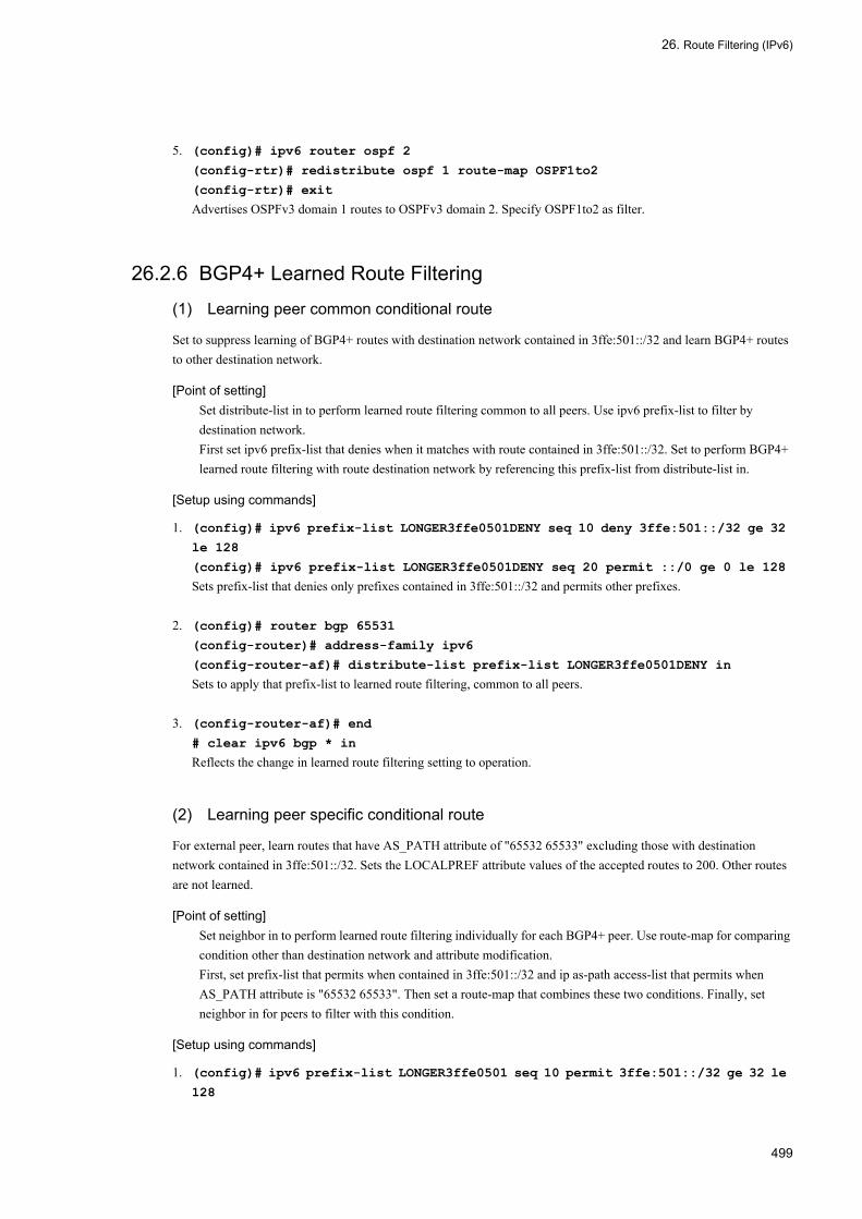
26. Route Filtering (IPv6)
5. (config)# ipv6 router ospf 2
(config-rtr)# redistribute ospf 1 route-map OSPF1to2
(config-rtr)# exit
Advertises OSPFv3 domain 1 routes to OSPFv3 domain 2. Specify OSPF1to2 as filter.
26.2.6 BGP4+ Learned Route Filtering
(1) Learning peer common conditional route
Set to suppress learning of BGP4+ routes with destination network contained in 3ffe:501::/32 and learn BGP4+ routes to other destination network.
[Point of setting]Set distribute-list in to perform learned route filtering common to all peers. Use ipv6 prefix-list to filter by destination network.First set ipv6 prefix-list that denies when it matches with route contained in 3ffe:501::/32. Set to perform BGP4+ learned route filtering with route destination network by referencing this prefix-list from distribute-list in.
[Setup using commands]
1. (config)# ipv6 prefix-list LONGER3ffe0501DENY seq 10 deny 3ffe:501::/32 ge 32
le 128
(config)# ipv6 prefix-list LONGER3ffe0501DENY seq 20 permit ::/0 ge 0 le 128
Sets prefix-list that denies only prefixes contained in 3ffe:501::/32 and permits other prefixes.
2. (config)# router bgp 65531
(config-router)# address-family ipv6
(config-router-af)# distribute-list prefix-list LONGER3ffe0501DENY in
Sets to apply that prefix-list to learned route filtering, common to all peers.
3. (config-router-af)# end
# clear ipv6 bgp * in
Reflects the change in learned route filtering setting to operation.
(2) Learning peer specific conditional route
For external peer, learn routes that have AS_PATH attribute of "65532 65533" excluding those with destination network contained in 3ffe:501::/32. Sets the LOCALPREF attribute values of the accepted routes to 200. Other routes are not learned.
[Point of setting]Set neighbor in to perform learned route filtering individually for each BGP4+ peer. Use route-map for comparing condition other than destination network and attribute modification.First, set prefix-list that permits when contained in 3ffe:501::/32 and ip as-path access-list that permits when AS_PATH attribute is "65532 65533". Then set a route-map that combines these two conditions. Finally, set neighbor in for peers to filter with this condition.
[Setup using commands]
1. (config)# ipv6 prefix-list LONGER3ffe0501 seq 10 permit 3ffe:501::/32 ge 32 le
128
499

26. Route Filtering (IPv6)
Sets prefix-list that permits when prefix is contained in 3ffe:501::/32.
2. (config)# ip as-path access-list 2 permit "^65532_65533$"
Sets ip as-path access-list that permits when AS_PATH attribute is "65532 65533".
3. (config)# route-map BGP65532IN deny 10
(config-route-map)# match ipv6 address prefix-list LONGER3ffe0501
(config-route-map)# exit
Sets route-map BGP65502IN to deny when destination network is contained in 3ffe:501::/32.
4. (config)# route-map BGP65532IN permit 20
(config-route-map)# match as-path 2
(config-route-map)# set local-preference 200
(config-route-map)# exit
Sets to set LOCAL_PATH attribute to 200 and permit when AS_PATH attribute matches with "65532 65533". Routes that do not match with any of these conditions will be denied because BGP65532IN does not have any other condition.
5. (config)# router bgp 65531
(config-router)# neighbor 3ffe:502:811:1::1 remote-as 65532
(config-router)# address-family ipv6
(config-router-af)# neighbor 3ffe:502:811:1::1 route-map BGP65532IN in
Sets to use BGP65532IN for receive route filtering of external peer.
6. (config-router-af)# end
# clear ipv6 bgp * in
Reflects the change in learned route filtering setting to operation.
26.2.7 BGP4+ Route Advertisement Filtering
(1) Advertising route of other protocols
Among direct connection routes and static routes, advertise to BGP4+ only routes for which the destination network is internal to the local AS network (3ffe:501::/32).
[Point of setting]Set redistribute to advertise routes that are not advertised by default. Specify the protocol of the route that needs to be advertised for redistribute.Specify for redistribute the route-map of route advertising condition. Use prefix-list to specify the destination network condition in the route-map.
[Setup using commands]
1. (config)# ipv6 prefix-list LONGER3ffe0501 seq 10 permit 3ffe:501::/32 ge 32 le
128
Sets prefix-list that permits only routes contained in 3ffe:501::/32.
2. (config)# route-map LONGER3ffe0501PERMIT permit 10
(config-route-map)# match ipv6 address prefix-list LONGER3ffe0501
(config-route-map)# exit
500

26. Route Filtering (IPv6)
Sets route-map that permits only routes contained in 3ffe:501::/32.
3. (config)# router bgp 65531
(config-router)# address-family ipv6
(config-router-af)# redistribute connected route-map LONGER3ffe0501PERMIT
(config-router-af)# redistribute static route-map LONGER3ffe0501PERMIT
For direct connection routes and static routes, sets redistribute to advertise only routes for which the result of filtering with LONGER3ffe0501PERMIT is permit.
4. (config-router-af)# end
#clear ipv6 bgp * out
Reflects the change in route advertisement filtering setting to operation.
(2) Checking route advertisement for each peer
For advertisement to external peer, restrict to advertise only BGP4+ routes with one AS path length received from AS100, and direct connection routes and static routes for which the network in the local AS is the destination (contained in 3ffe:501::/32). When advertising, two AS_PATH AS numbers are added to peer 3ffe:502:812:1::1. Only BGP4+ routes are advertised to internal peer.
[Point of setting]Set neighbor out if route filtering is necessary individually for each peer.In this case, set route-maps for direct connection route/static route redistribute, for peer 3ffe:502:812:1::1 advertising, for external peers other than 3ffe:502:812:1::1, and for internal peer.For direct connection routes/static routes, set ipv6 prefix-list that permits only routes contained in 3ffe:501::/32 and set route-map that references this.For peer 3ffe:502:812:1::1, set route-map that adds two ASs only when route protocol is direct connection of static.For external peer other than 3ffe:502:812:1::1, set ip as-path access-list that permits only AS_PATH attribute with one AS and set route-map that references this.For internal peer, set route-map that permits only BGP4+ routes and denies others.
[Setup using commands]
1. (config)# ipv6 prefix-list LONGER3ffe0501 seq 10 permit 3ffe:501::/32 ge 32 le
128
(config)# route-map LONGER3ffe0501PERMIT permit 10
(config-route-map)# match ipv6 address prefix-list LONGER3ffe0501
(config-route-map)# exit
Sets route-map that permits only routes contained in 3ffe:501::/32. Use for redistribute of direct connection routes/static routes.
2. (config)# ip as-path access-list 1 permit "^[0-9]+$"
(config)# route-map BGPEXTOUT permit 10
(config-route-map)# match protocol connected static
(config-route-map)# exit
(config)# route-map BGPEXTOUT permit 20
(config-route-map)# match protocol bgp
(config-route-map)# match as-path 1
(config-route-map)# exit
Sets route-map that accepts only routes with one AS number of AS_PATH attribute among direct connection routes, static routes, and BGP4+ routes. Use to advertise to external peers.
501

26. Route Filtering (IPv6)
3. (config)# route-map BGP81211OUT permit 10
(config-route-map)# match protocol connected static
(config-route-map)# set as-path prepend count 2
(config-route-map)# exit
(config)# route-map BGP81211OUT permit 20
(config-route-map)# match protocol bgp
(config-route-map)# match as-path 1
(config-route-map)# set as-path prepend count 2
(config-route-map)# exit
Sets route-map that accepts only routes with one AS number of AS_PATH attribute and adds two ASs among direct connection routes, static routes, and BGP4+ routes. Use this to advertise to peer 3ffe:502:812:1::1.
4. (config)# route-map BGPINTOUT permit 10
(config-route-map)# match protocol bgp
(config-route-map)# exit
Sets route-map that permits only BGP4+ routes. Use to advertise to internal peers.
5. (config)# router bgp 65531
(config-router)# address-family ipv6
(config-router-af)# redistribute connected route-map LONGER3ffe0501PERMIT
(config-router-af)# redistribute static route-map LONGER3ffe0501PERMIT
(config-router-af)# exit
For direct connection routes and static routes, sets redistribute to advertise only routes for which the result of filtering with route-map LONGER3ffe0501PERMIT is permit.
6. (config-router)# neighbor 3ffe:502:811:1::1 remote-as 65532
(config-router)# address-family ipv6
(config-router-af)# neighbor 3ffe:502:811:1::1 route-map BGPEXTOUT out
(config-router-af)# exit
Uses BGPEXTOUT to filter advertised route to external peer.
7. (config-router)# neighbor 3ffe:502:812:1::1 remote-as 65533
(config-router)# address-family ipv6
(config-router-af)# neighbor 3ffe:502:812:1::1 route-map BGP81211OUT out
(config-router-af)# exit
Uses BGP81211OUT to filter advertised route to external peer 3ffe:502:812:1::1.
8. (config-router)# neighbor 3ffe:501:811:ff01::1 remote-as 65531
(config-router)# address-family ipv6
(config-router-af)# neighbor 3ffe:501:811:ff01::1 route-map BGPINTOUT out
Uses BGPINTOUT to filter advertised route to internal peer.
9. (config-router-af)# end
#clear ipv6 bgp * out
Reflects the change in route advertisement filtering setting to operation.
502

26. Route Filtering (IPv6)
26.3 Operation
The following table provides a list of route filtering (IPv6) operation commands.
Table 26-21: List of Operation Commands
26.3.1 Checking Route Received by RIPng (before Learned Route Filtering)
Execute the operation command show ipv6 rip with the parameter received-routes to check the routes received by RIPng.
Figure 26-2: Display Example of RIPng Received Route
> show ipv6 rip received-routesDate 2005/07/14 12:00:00 UTCStatus Codes: * valid, > active Neighbor Address: fe80::200:87ff:fe28:90d7%VLAN0007 Destination Next Hop Interface Metric Tag Timer*> 3ffe:3b01:6705:1::/64 fe80::200:87ff:fe28:90d7%VLAN0007 VLAN0007 1 0 5s
NoteThis command does not display routes suppressed from learning by learned route filtering and RIPng internal routes not given priority.
26.3.2 Checking Route from OSPFv3 SPF Calculation Even if invalidated by filter, AS external routes resulting from SPF calculation by OSPFv3 are entered in the routing table as invalid routes. Execute the show ipv6 route command specifying the all-routes parameter together with -T ospf_external to check AS external routes, including invalid routes, resulting from SPF calculation by OSPFv3.
Command Description
clear ipv6 bgp Clears BGP4+ session and BGP4+ protocol related information and filters receive/send route using the new BGP filter information.
dump protocols unicast Outputs the trace information and control table information collected by a unicast routing program to a file.
erase protocol-dump unicast Deletes the trace information file and control table information file created by a unicast routing program.
restart unicast Restarts the unicast routing program.
show ipv6 bgp Displays BGP4+ protocol information.
show ipv6 entry Displays detailed information on specific IPv6 unicast route.
show ipv6 ospf Displays OSPFv3 protocol information.
show ipv6 rip Displays RIPng protocol information.
show ipv6 route Displays a list of IPv6 unicast routes.
503
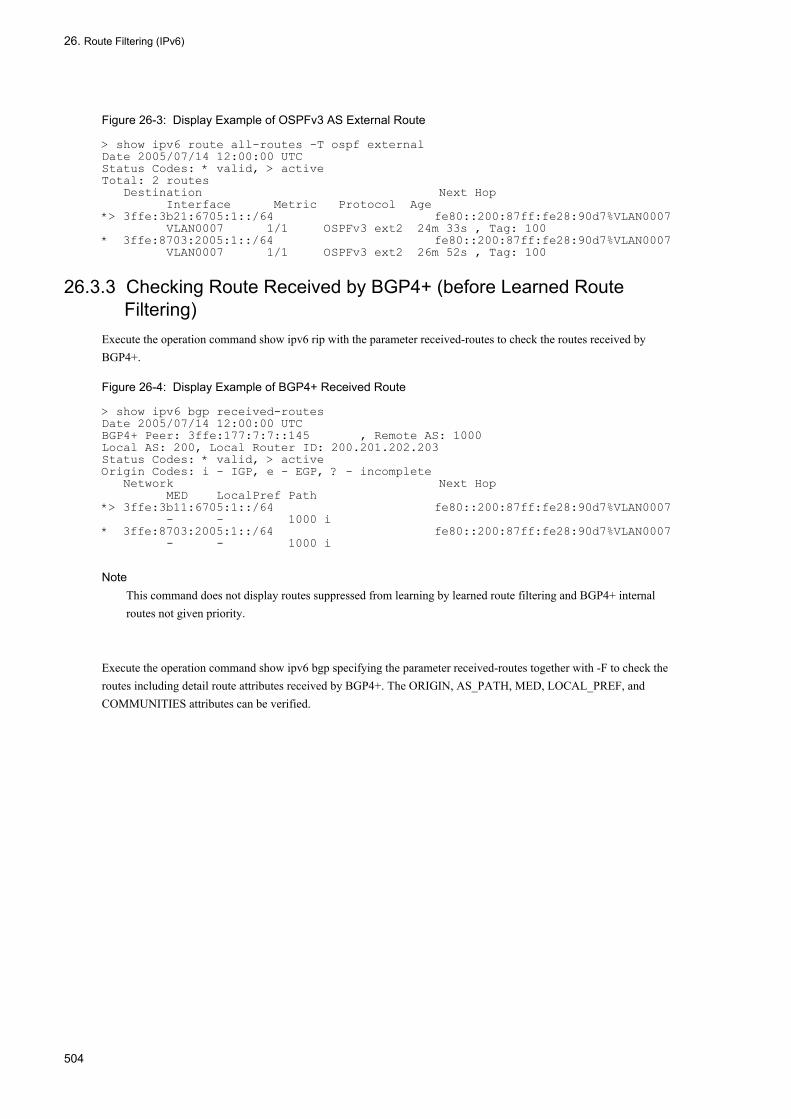
26. Route Filtering (IPv6)
Figure 26-3: Display Example of OSPFv3 AS External Route
> show ipv6 route all-routes -T ospf externalDate 2005/07/14 12:00:00 UTCStatus Codes: * valid, > activeTotal: 2 routes Destination Next Hop Interface Metric Protocol Age*> 3ffe:3b21:6705:1::/64 fe80::200:87ff:fe28:90d7%VLAN0007 VLAN0007 1/1 OSPFv3 ext2 24m 33s , Tag: 100* 3ffe:8703:2005:1::/64 fe80::200:87ff:fe28:90d7%VLAN0007 VLAN0007 1/1 OSPFv3 ext2 26m 52s , Tag: 100
26.3.3 Checking Route Received by BGP4+ (before Learned Route Filtering)
Execute the operation command show ipv6 rip with the parameter received-routes to check the routes received by BGP4+.
Figure 26-4: Display Example of BGP4+ Received Route
> show ipv6 bgp received-routesDate 2005/07/14 12:00:00 UTCBGP4+ Peer: 3ffe:177:7:7::145 , Remote AS: 1000Local AS: 200, Local Router ID: 200.201.202.203Status Codes: * valid, > activeOrigin Codes: i - IGP, e - EGP, ? - incomplete Network Next Hop MED LocalPref Path*> 3ffe:3b11:6705:1::/64 fe80::200:87ff:fe28:90d7%VLAN0007 - - 1000 i* 3ffe:8703:2005:1::/64 fe80::200:87ff:fe28:90d7%VLAN0007 - - 1000 i
NoteThis command does not display routes suppressed from learning by learned route filtering and BGP4+ internal routes not given priority.
Execute the operation command show ipv6 bgp specifying the parameter received-routes together with -F to check the routes including detail route attributes received by BGP4+. The ORIGIN, AS_PATH, MED, LOCAL_PREF, and COMMUNITIES attributes can be verified.
504

26. Route Filtering (IPv6)
Figure 26-5: Display Example of BGP4+ Received Route Detail
> show ipv6 bgp received-routes -FDate 2005/07/14 12:00:00 UTCBGP4+ Peer: 3ffe:177:7:7::145 , Remote AS: 1000Local AS: 200, Local Router ID: 200.201.202.203Status Codes: * valid, > activeRoute 3ffe:3b11:6705:1::/64*> Next Hop fe80::200:87ff:fe28:90d7%VLAN0007 MED: -, LocalPref: -, Type: External route Origin: IGP, IGP Metric: 0 Path: 1000 Next Hop Attribute: 3ffe:177:7:7::145 fe80::200:87ff:fe28:90d7 Route 3ffe:8703:2005:1::/64* Next Hop fe80::200:87ff:fe28:90d7%VLAN0007 MED: -, LocalPref: -, Type: External route Origin: IGP, IGP Metric: 0 Path: 1000 Next Hop Attribute: 3ffe:177:7:7::145 fe80::200:87ff:fe28:90d7 Communities: 300:300
NoteThis command does not display routes suppressed from learning by learned route filtering and BGP4+ internal routes not given priority.
26.3.4 Checking Route from Learned Route FilteringRoutes resulting from learned route filtering are entered in the routing table. The learned route filtering result can be determined by display the routes in the routing table.
Execute the operation command show ipv6 route with the parameter all-routes to display all routes in the routing table including invalid routes.
Figure 26-6: Display Example of Routing Table Route (Including Invalid Routes)
> show ipv6 route all-routesDate 2005/07/14 12:00:00 UTCStatus Codes: * valid, > activeTotal: 11 routes Destination Next Hop Interface Metric Protocol Age*> ::1/128 ::1 - localhost 0/0 Connected 4h 44m |*> 3ffe:177:7:7::/64 3ffe:177:7:7::1 | VLAN0007 0/0 Connected 39m 41s |* 3ffe:177:7:7::/64 3ffe:177:7:7::1 | VLAN0007 1/- OSPFv3 intra 6m 52s |*> 3ffe:177:7:7::1/128 ::1 | localhost 0/0 Connected 39m 41s |*> 3ffe:3b01:6705:1::/64 fe80::200:87ff:fe28:90d7%VLAN0007 | VLAN0007 2/0 RIPng 2s |*> 3ffe:3b11:6705:1::/64 fe80::200:87ff:fe28:90d7%VLAN0007 |* VLAN0007 -/- BGP4+ 4m 5s |*> 3ffe:3b21:6705:1::/64 fe80::200:87ff:fe28:90d7%VLAN0007 | VLAN0007 1/1 OSPFv3 ext2 4m 3s |*> 3ffe:8703:2005:1::/64 3ffe:177:7:7::145 | VLAN0007 0/0 Static 1m 15s |* 3ffe:8703:2005:1::/64 fe80::200:87ff:fe28:90d7%VLAN0007 | VLAN0007 -/- BGP4+ 8m 27s |* 3ffe:8703:2005:1::/64 fe80::200:87ff:fe28:90d7%VLAN0007 | VLAN0007 1/1 OSPFv3 ext2 6m 22s |* 3ffe:8703:2005:1::/64 fe80::200:87ff:fe28:90d7%VLAN0007 | VLAN0007 2/0 RIPng 2s -
*
505

26. Route Filtering (IPv6)
The meaning of * and > at the beginning of the line are as follows: *: The route is a valid route. Route without * is an invalid route. >: The route is a priority route. Only priority routes are used for packet transfer.
Execute the operation command show ipv6 route specifying the parameter all-routes together with the protocol name to check routes in the routing table only for specific learning source protocol.
Figure 26-7: Display Example of Routing Table Route (Including Invalid Routes for RIPng Only)
> show ipv6 route all-routes ripDate 2005/07/14 12:00:00 UTCStatus Codes: * valid, > activeTotal: 2 routes Destination Next Hop Interface Metric Protocol Age*> 3ffe:3b01:6705:1::/64 fe80::200:87ff:fe28:90d7%VLAN0007 VLAN0007 2/0 RIPng 3s* 3ffe:8703:2005:1::/64 fe80::200:87ff:fe28:90d7%VLAN0007 VLAN0007 2/0 RIPng 3s
The protocol and priority of priority route must be checked when various routing protocols are learning and using routes for a single destination network. The priority is determined by the distance value.
Execute the operation command show ipv6 route specifying the parameter all-routes together with -P to display the route distance values. The first value of the Distance item at the end of the line is the distance value.
Figure 26-8: Display Example of Route Distance Value in Routing Table
> show ipv6 route all-routes -PDate 2005/07/14 12:00:00 UTCStatus Codes: * valid, > activeTotal: 11 routes Destination Next Hop Interface Metric Protocol Age*> ::1/128 ::1 localhost 0/0 Connected 4h 46m , Distance: 0/0/0*> 3ffe:177:7:7::/64 3ffe:177:7:7::1 VLAN0007 0/0 Connected 42m 0s , Distance: 0/0/0* 3ffe:177:7:7::/64 3ffe:177:7:7::1 VLAN0007 1/- OSPFv3 intra 9m 11s , Distance: 110/1/0*> 3ffe:177:7:7::1/128 ::1 localhost 0/0 Connected 42m 0s , Distance: 0/0/0*> 3ffe:3b01:6705:1::/64 fe80::200:87ff:fe28:90d7%VLAN0007 VLAN0007 2/0 RIPng 16s , Distance: 120/0/0*> 3ffe:3b11:6705:1::/64 fe80::200:87ff:fe28:90d7%VLAN0007 VLAN0007 -/- BGP4+ 6m 24s , Distance: 20/0/0*> 3ffe:3b21:6705:1::/64 fe80::200:87ff:fe28:90d7%VLAN0007 VLAN0007 1/1 OSPFv3 ext2 6m 22s , Distance: 110/1/0*> 3ffe:8703:2005:1::/64 3ffe:177:7:7::145 VLAN0007 0/0 Static 3m 34s , Distance: 2/0/0* 3ffe:8703:2005:1::/64 fe80::200:87ff:fe28:90d7%VLAN0007 VLAN0007 -/- BGP4+ 10m 46s , Distance: 20/0/0* 3ffe:8703:2005:1::/64 fe80::200:87ff:fe28:90d7%VLAN0007 VLAN0007 1/1 OSPFv3 ext2 8m 41s , Distance: 110/1/0* 3ffe:8703:2005:1::/64 fe80::200:87ff:fe28:90d7%VLAN0007 VLAN0007 2/0 RIPng 16s , Distance: 120/0/0
Execute the operation command show ipv6 route specifying the parameter all-routes together with the destination network to display the distance values only for routes to specific destination network. The first value of the Distance display line in the detail information is the distance value.
506

26. Route Filtering (IPv6)
Figure 26-9: Display Example of Routing Table Route (Including Invalid Routes, Specific Destination Only)
> show ipv6 route all-routes 3ffe:8703:2005:1::/64Date 2005/07/14 12:00:00 UTCRoute codes: * = active, + = changed to active recently ' ' = inactive, - = changed to inactive recently Route 3ffe:8703:2005:1::/64Entries 4 Announced 1 Depth 0 <> * NextHop 3ffe:177:7:7::145, Interface: VLAN0007 Protocol <Static> Source Gateway ---- Metric/2 : 0/0 Distance/2/3: 2/0/0 Tag : 0, Age : 4m 35s AS Path : IGP (Id 1) Communities: - LocalPref : - RT State: <Remote Int Active Gateway> NextHop fe80::200:87ff:fe28:90d7%VLAN0007, Interface: VLAN0007 Protocol <BGP4+> Source Gateway fe80::200:87ff:fe28:90d7%VLAN0007 Metric/2 : -/- Distance/2/3: 20/0/0 Tag : 0, Age : 11m 47s AS Path : 1000 IGP (Id 3) Communities: - LocalPref : 100 RT State: <Ext Gateway>
Execute the operation command show ipv6 route specifying the parameter all-routes together with -F to check the detail route attributes of routes in the routing table.
507

26. Route Filtering (IPv6)
Figure 26-10: Display Example of Routing Table Route (Including Invalid Routes, Detail Display)
> show ipv6 route all-routes -FDate 2005/07/14 12:00:00 UTCStatus Codes: * valid, > activeTotal: 11 routes Destination Next Hop Interface Metric Protocol Age*> ::1/128 ::1 localhost 0/0 Connected 4h 55m , Distance: 0/0/0, Tag: 0, AS-Path: IGP (Id 1), Communities: -, LocalPref: -, <NoAdvise Active Retain>*> 3ffe:177:7:7::/64 3ffe:177:7:7::1 VLAN0007 0/0 Connected 51m 2s , Distance: 0/0/0, Tag: 0, AS-Path: IGP (Id 1), Communities: -, LocalPref: -, <Active Retain>* 3ffe:177:7:7::/64 3ffe:177:7:7::1 VLAN0007 1/- OSPFv3 intra 18m 13s , Distance: 110/1/0, Tag: 0,AS-Path: IGP (Id 1), Communities: -, LocalPref: -, <Int Gateway>*> 3ffe:177:7:7::1/128 ::1 localhost 0/0 Connected 51m 2s , Distance: 0/0/0, Tag: 0, AS-Path: IGP (Id 1), Communities: -, LocalPref: -, <NoAdvise Int Active Retain>*> 3ffe:3b01:6705:1::/64 fe80::200:87ff:fe28:90d7%VLAN0007 VLAN0007 2/0 RIPng 4s , Distance: 120/0/0, Tag: 0,AS-Path: IGP (Id 1), Communities: -, LocalPref: -, <Int Active Gateway>*> 3ffe:3b11:6705:1::/64 fe80::200:87ff:fe28:90d7%VLAN0007 VLAN0007 -/- BGP4+ 3m 6s , Distance: 20/0/0, Tag: 0, AS-Path: 1000 IGP (Id 3), Communities: -, LocalPref: 100, <Ext Active Gateway>*> 3ffe:3b21:6705:1::/64 fe80::200:87ff:fe28:90d7%VLAN0007 VLAN0007 1/1 OSPFv3 ext2 15m 24s , Distance: 110/1/0, Tag: 0, AS-Path: IGP (Id 1), Communities: -, LocalPref: -, <Int Ext Active Gateway>*> 3ffe:8703:2005:1::/64 3ffe:177:7:7::145 VLAN0007 0/0 Static 12m 36s , Distance: 2/0/0, Tag: 0, AS-Path: IGP (Id 1), Communities: -, LocalPref: -, <Remote Int Active Gateway>* 3ffe:8703:2005:1::/64 fe80::200:87ff:fe28:90d7%VLAN0007 VLAN0007 -/- BGP4+ 3m 6s , Distance: 20/0/0, Tag: 0, AS-Path: 1000 IGP (Id 5), Communities: 300:300, LocalPref: 100, <Ext Gateway>* 3ffe:8703:2005:1::/64 fe80::200:87ff:fe28:90d7%VLAN0007 VLAN0007 1/1 OSPFv3 ext2 17m 43s , Distance: 110/1/0, Tag: 0, AS-Path: IGP (Id 1), Communities: -, LocalPref: -, <Int Ext Gateway>* 3ffe:8703:2005:1::/64 fe80::200:87ff:fe28:90d7%VLAN0007 VLAN0007 2/0 RIPng 4s , Distance: 120/0/0, Tag: 0,AS-Path: IGP (Id 1), Communities: -, LocalPref: -, <Int Gateway>
26.3.5 Checking Route before Route Advertisement FilteringRoutes subject to advertising are basically priority routes in the routing table. Display the routes in the routing table to check the routes subject to route advertisement filtering.
Execute the operation command show ipv6 route to display the priority routes in the routing table.
Figure 26-11: Display Example of Routing Table Route
> show ipv6 routeDate 2005/07/14 12:00:00 UTCTotal: 7 routesDestination Next Hop Interface Metric Protocol Age::1/128 ::1 localhost 0/0 Connected 5h 7m3ffe:177:7:7::/64 3ffe:177:7:7::1 VLAN0007 0/0 Connected 1h 2m3ffe:177:7:7::1/128 ::1 localhost 0/0 Connected 1h 2m3ffe:3b01:6705:1::/64 fe80::200:87ff:fe28:90d7%VLAN0007 VLAN0007 2/0 RIPng 35s3ffe:3b11:6705:1::/64 fe80::200:87ff:fe28:90d7%VLAN0007 VLAN0007 -/- BGP4+ 14m 29s3ffe:3b21:6705:1::/64 fe80::200:87ff:fe28:90d7%VLAN0007 VLAN0007 1/1 OSPFv3 ext2 26m 47s3ffe:8703:2005:1::/64 3ffe:177:7:7::145 VLAN0007 0/0 Static 23m 59s
508
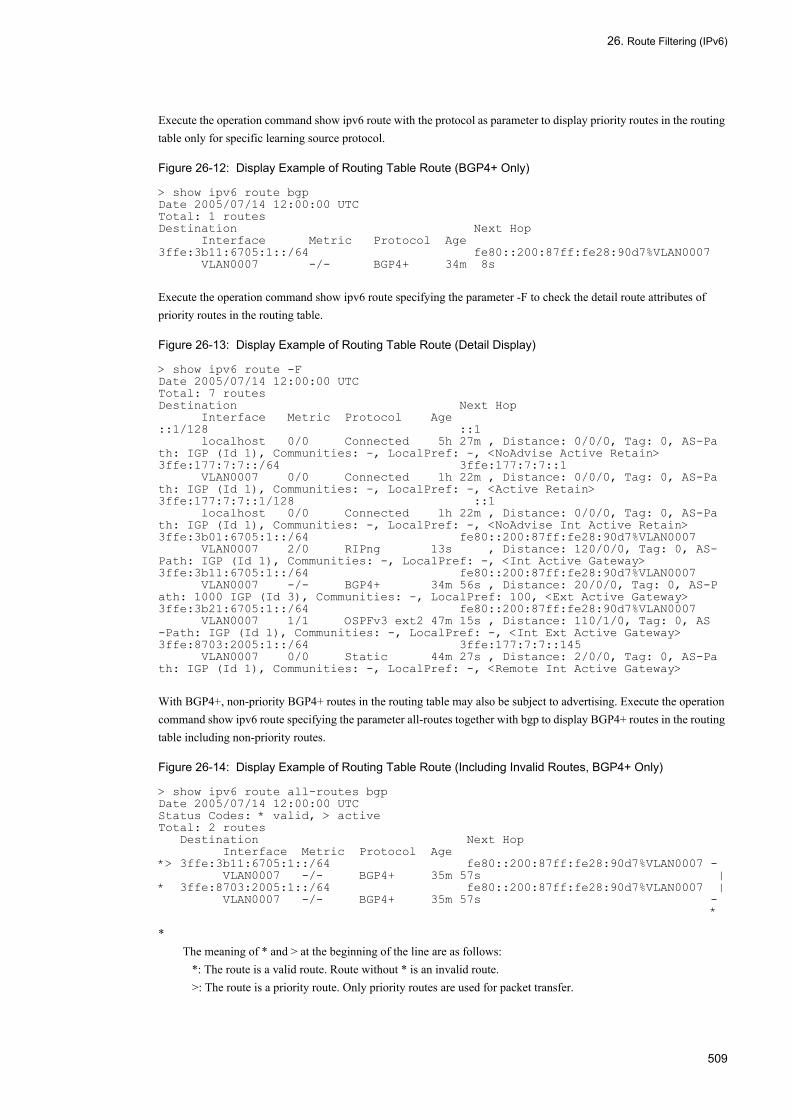
26. Route Filtering (IPv6)
Execute the operation command show ipv6 route with the protocol as parameter to display priority routes in the routing table only for specific learning source protocol.
Figure 26-12: Display Example of Routing Table Route (BGP4+ Only)
> show ipv6 route bgpDate 2005/07/14 12:00:00 UTCTotal: 1 routesDestination Next Hop Interface Metric Protocol Age3ffe:3b11:6705:1::/64 fe80::200:87ff:fe28:90d7%VLAN0007 VLAN0007 -/- BGP4+ 34m 8s
Execute the operation command show ipv6 route specifying the parameter -F to check the detail route attributes of priority routes in the routing table.
Figure 26-13: Display Example of Routing Table Route (Detail Display)
> show ipv6 route -FDate 2005/07/14 12:00:00 UTCTotal: 7 routesDestination Next Hop Interface Metric Protocol Age::1/128 ::1 localhost 0/0 Connected 5h 27m , Distance: 0/0/0, Tag: 0, AS-Path: IGP (Id 1), Communities: -, LocalPref: -, <NoAdvise Active Retain>3ffe:177:7:7::/64 3ffe:177:7:7::1 VLAN0007 0/0 Connected 1h 22m , Distance: 0/0/0, Tag: 0, AS-Path: IGP (Id 1), Communities: -, LocalPref: -, <Active Retain>3ffe:177:7:7::1/128 ::1 localhost 0/0 Connected 1h 22m , Distance: 0/0/0, Tag: 0, AS-Path: IGP (Id 1), Communities: -, LocalPref: -, <NoAdvise Int Active Retain>3ffe:3b01:6705:1::/64 fe80::200:87ff:fe28:90d7%VLAN0007 VLAN0007 2/0 RIPng 13s , Distance: 120/0/0, Tag: 0, AS-Path: IGP (Id 1), Communities: -, LocalPref: -, <Int Active Gateway>3ffe:3b11:6705:1::/64 fe80::200:87ff:fe28:90d7%VLAN0007 VLAN0007 -/- BGP4+ 34m 56s , Distance: 20/0/0, Tag: 0, AS-Path: 1000 IGP (Id 3), Communities: -, LocalPref: 100, <Ext Active Gateway>3ffe:3b21:6705:1::/64 fe80::200:87ff:fe28:90d7%VLAN0007 VLAN0007 1/1 OSPFv3 ext2 47m 15s , Distance: 110/1/0, Tag: 0, AS-Path: IGP (Id 1), Communities: -, LocalPref: -, <Int Ext Active Gateway>3ffe:8703:2005:1::/64 3ffe:177:7:7::145 VLAN0007 0/0 Static 44m 27s , Distance: 2/0/0, Tag: 0, AS-Path: IGP (Id 1), Communities: -, LocalPref: -, <Remote Int Active Gateway>
With BGP4+, non-priority BGP4+ routes in the routing table may also be subject to advertising. Execute the operation command show ipv6 route specifying the parameter all-routes together with bgp to display BGP4+ routes in the routing table including non-priority routes.
Figure 26-14: Display Example of Routing Table Route (Including Invalid Routes, BGP4+ Only)
> show ipv6 route all-routes bgpDate 2005/07/14 12:00:00 UTCStatus Codes: * valid, > activeTotal: 2 routes Destination Next Hop Interface Metric Protocol Age*> 3ffe:3b11:6705:1::/64 fe80::200:87ff:fe28:90d7%VLAN0007 - VLAN0007 -/- BGP4+ 35m 57s |* 3ffe:8703:2005:1::/64 fe80::200:87ff:fe28:90d7%VLAN0007 | VLAN0007 -/- BGP4+ 35m 57s - *
*The meaning of * and > at the beginning of the line are as follows: *: The route is a valid route. Route without * is an invalid route. >: The route is a priority route. Only priority routes are used for packet transfer.
509

26. Route Filtering (IPv6)
26.3.6 Checking RIPng Advertised RouteExecute the operation command show ipv6 rip with the parameter advertised-routes to check the RIPng advertised routes. The advertise destination interface name and the advertised route/route attributes are displayed.
Figure 26-15: Display Example of RIPng Advertised Route
> show ipv6 rip advertised-routesDate 2005/07/14 12:00:00 UTC Target Interface: VLAN0006Destination Next Hop Interface Metric Tag Age3ffe:3b01:6705:1::/64 fe80::200:87ff:fe28:90d7%VLAN0007 VLAN0007 2 0 3s
26.3.7 Checking OSPFv3 Advertised Route With OSPFv3, routes advertised by route advertisement filtering are contained in AS-External-LSA.
Execute the operation command show ipv6 ospf specifying the parameters database, external, and self-originate to check the items in AS-External-LSA generated by the local system.
Figure 26-16: Display Example of AS-External-LSA (Local System Generated Only)
> show ipv6 ospf database external self-originateDate 2005/07/14 12:00:00 UTCDomain: 1Local Router ID: 177.7.7.4LS Database: AS-external-LSAAdvertising Router: 177.7.7.4 LSID: 0000000a, Age: 298, Length: 36 Sequence: 80000001, Checksum: 6c76 Prefix: 3ffe:177:7:7::/64 ...1 Prefix Options: <> Type: 2, Metric: 20, Tag: 100
1. Prefix (3ffe:177:7:7::/64) indicates the route destination network.
26.3.8 Checking BGP4+ Advertised Route Execute the operation command show ipv6 bgp with the parameter advertised-routes to check the BGP4+ advertised routes.
Figure 26-17: Display Example of BGP4+ Advertised Route
> show ipv6 bgp advertised-routesDate 2005/07/14 12:00:00 UTCBGP4+ Peer: 3ffe:192:158:1::145 , Remote AS: 1000Local AS: 200, Local Router ID: 200.201.202.203Origin Codes: i - IGP, e - EGP, ? - incompleteNetwork Next Hop MED LocalPref Path3ffe:3b11:6705:1::/64 fe80::200:87ff:fe28:90d7%VLAN0007 - - 200 1000 i3ffe:8703:2005:1::/64 fe80::200:87ff:fe28:90d7%VLAN0007 - - 200 1000 i
Execute the operation command show ipv6 bgp specifying the parameter advertised-routes together with -F to check the detail route attributes of BGP4+ advertised routes. The ORIGIN, AS_PATH, MED, LOCAL_PREF, and COMMUNITIES attributes can be verified.
510
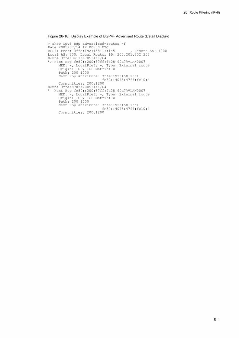
26. Route Filtering (IPv6)
Figure 26-18: Display Example of BGP4+ Advertised Route (Detail Display)
> show ipv6 bgp advertised-routes -FDate 2005/07/14 12:00:00 UTCBGP4+ Peer: 3ffe:192:158:1::145 , Remote AS: 1000Local AS: 200, Local Router ID: 200.201.202.203Route 3ffe:3b11:6705:1::/64*> Next Hop fe80::200:87ff:fe28:90d7%VLAN0007 MED: -, LocalPref: -, Type: External route Origin: IGP, IGP Metric: 0 Path: 200 1000 Next Hop Attribute: 3ffe:192:158:1::1 fe80::4048:47ff:fe10:4 Communities: 200:1200Route 3ffe:8703:2005:1::/64* Next Hop fe80::200:87ff:fe28:90d7%VLAN0007 MED: -, LocalPref: -, Type: External route Origin: IGP, IGP Metric: 0 Path: 200 1000 Next Hop Attribute: 3ffe:192:158:1::1 fe80::4048:47ff:fe10:4 Communities: 200:1200
511

26. Route Filtering (IPv6)
512

27. General Description of IPv6 Multicast
27General Description of IPv6 MulticastMulticast sends the same information to groups selected in a network. This chapter describes the multicast realized on an IPv6 network.
27.1 IPv6 Multicast Overview
27.2 IPv6 Group Management Function
27.3 IPv6 Multicast Relay Function
27.4 IPv6 Route Control Function
27.5 Network Design Concept
513

27. General Description of IPv6 Multicast
27.1 IPv6 Multicast Overview
The IPv6 multicast realizes similar functions to those of the IPv4 multicast by IPv6. For details of IPv4 multicast, see "13.1 IPv4 Multicast Overview". The IPv4 multicast and the IPv6 multicast operate completely independently. Therefore, the IPv4 multicast and the IPv6 multicast can be set as completely independent functions even in the same router.
27.1.1 IPv6 Multicast AddressIPv6 multicast communication uses an IPv6 address whose upper 8 bits are ff as the destination address. The IPv6 multicast address exists only among the groups joining in transmission and reception of multicast data as a logical address. The table below shows the format of the IPv6 multicast address.
Figure 27-1: Multicast Address Format
27.1.2 IPv6 Multicast Routing FunctionThe LANSW module forwards received IPv6 multicast packets according to the IPv6 multicast forwarding entry. The multicast routing function consists primarily of the three functions given below.
• IPv6 group management functionThis function sends and receives IPv6 group membership information and learns of the existence of IPv6 multicast groups. The Multicast Listener Discovery (MLD) is used in the LANSW module.
• IPv6 route control functionThis function sends and receives route information, determines the forwarding route, and creates IPv6 multicast route information and IPv6 multicast forwarding entry. PIM-SM (including PIM-SSM) is used for collecting route information.
• IPv6 forwarding functionThis function forwards IPv6 multicast packets via hardware and software according to the IPv6 multicast forwarding entry.It is possible to either provide the IPv6 multicast with a QoS function or filter unnecessary packets by using the IPv6 multicast relaying function in the LANSW module simultaneously with the QoS function and the filtering function.
514

27. General Description of IPv6 Multicast
27.2 IPv6 Group Management Function
The IPv6 group management function learns of the existence of an IPv6 multicast group member in the network to which a router is directly connected by sending and receiving the IPv6 group membership information between the router and host. The LANSW module supports MLD in order to realize the IPv6 group management function.
27.2.1 Outline of MLDMLD is an IPv6 multicast group management protocol used between the router and host, that takes the role of IGMP for IPv4 multicast.
With MLD, the router sends inquiry to the host having the IPv6 multicast group to recognize the state of the host by join or leave report returned from the host, and forwards or interrupts multicast packets. Apart from that it uses an IPv6 address for communications, it is exactly the same as IGMP.
RFC defines MLDv1 and MLDv2.
MLDv2, which is the extended version of MLDv1, is the protocol to implement IPv6 group management function that has source filtering function to receive packets only from the specified source. Allowing the source to be specified upon the join and leave to/from IPv6 multicast group, a combination of MLDv2 and PIM-SSM enables efficient IPv6 multicast relay.
The MLDv1 message formats and default values of the LANSW module comply with RFC2710. The MLDv2 message format and default values comply with RFC3810.
27.2.2 Operation of MLD
(1) Operation of MLDv1
The table below lists the specifications of MLDv1 message supported by the LANSW module.
Table 27-1: MLDv1 Messages
(Legend) Y: Supported N: Not supported
(2) Operation of MLDv2
MLDv2 realizes source filtering function by specifying the filter mode and the source list. Two filter modes are available:
• INCLUDE: Relays packets only from the specified sources in the list.• EXCLUDE: Relays packets from the sources other than the specified sources in the list.
Type Description Support
Transmission
Reception
Multicast Listener Query
General Query Sends inquiry regarding join in an IPv6 multicast group (For all groups)
Y Y
Group-Specific Query Sends inquiry regarding join in an IPv6 multicast group (For specific source and group).
Y Y
Multicast Listener Report Reports the joined IPv6 multicast group. N Y
Multicast Listener Done Reports the leave from an IPv6 multicast group. N Y
515

27. General Description of IPv6 Multicast
The table below lists the specifications of MLDv2 message supported by the LANSW module.
Table 27-2: MLDv2 Messages
(Legend) Y: Supported N: Not supported
The filter mode and source list can be changed after joining to group, by specifying them in the Multicast Address Record included in the Report message. The table below shows the Multicast Address Record types supported by the LANSW module.
Table 27-3: Multicast Address Record Types
(Legend) Y: Supported
MLDv1 operation by MLDv1 messages are described below.
• A multicast router sends Membership Query messages periodically to all node address ff02::1 in order to obtain IPv6 multicast membership information on the interface to which it is connected directly.
• When Multicast Listener Query is received, the host sends Multicast Listener Report to the corresponding group to report status of joining in the group.
• IPv6 multicast router adds the group to a membership list when it receives Multicast Listener Done from each host.• It deletes the group from the membership list when it receives a Multicast Listener Done message.
The figure below shows MLDv1 group join and leave.
Type Description Support
Transmission
Reception
Version 2 Multicast Listener Query
General Query Sends inquiry regarding join in an IPv6 multicast group (For all groups)
Y Y
Multicast Address Specific Query
Sends inquiry regarding join in an IPv6 multicast group (For specific source and group).
Y Y
Multicast Address and Source Specific Query
Sends inquiry regarding join in an IPv6 multicast group (For specific source and group).
Y Y
Version 2 MulticastListener Report
Current StateReport Reports the joined IPv6 multicast group and the filter mode.
N Y
State ChangeReport Reports the update of joined IPv6 multicast group and the filter mode.
N Y
Type Description Support
Current State Report MODE_IS_INCLUDE Indicates that the filter mode is INCLUDE.
Y
MODE_IS_EXCLUDE Indicates that the filter mode is EXCLUDE.
Y(The source list is ignored.)
State Change Report CHANGE_TO_ INCLUDE_MODE Indicates that the filter mode is changed to INCLUDE.
Y
CHANGE_TO_ EXCLUDE_MODE Indicates that the filter mode is changed to EXCLUDE.
Y(The source list is ignored.)
ALLOW_NEW_ SOURCES Indicates that the source to be allowed is added.
Y
BLOCK_OLD_ SOURCES Indicates that the allowed source is deleted.
Y
516

27. General Description of IPv6 Multicast
Figure 27-2: MLDv1 Group Join and Leave
MLDv2 operation by MLDv2 messages are described below.
• A multicast router sends Version 2 Multicast Listener Query (General Query) messages periodically to the link local and all node address ff02::1 in order to obtain IPv6 multicast membership information on the interface to which it is connected directly.
• When Version 2 Multicast Listener Query is received, the host sends Version 2 Multicast listener Report (Current State Report) to ff02::16 to report the status of joining in the group.
• When IPv6 multicast router receives the Version 2 Multicast Listener Report (State Change Report) message from the host, it adds/deletes the group to/from the membership list according to the Multicast Address Record type.
The figure below shows the transmission operation of MLDv2 message from the host.
517

27. General Description of IPv6 Multicast
Figure 27-3: MLDv2 Group Join and Leave
27.2.3 Querier DesignationThe MLD router plays either one of the roles of Querier or Non-Querier. If a multiple number of routers exist on one network, one of them becomes the Querier to transmit periodical Multicast Listener Query messages.
In deciding the Querier, comparison is made between the source IPv6 link local address of the Multicast Listener Query received from MLD routers existing on the same network and the IPv6 link local address of the interface. If the address on the interface is smaller, it operates as the Querier. If the address on the interface is larger, it becomes a Non-Querier, and does not transmit the Multicast Listener Query.
The above operations allow only one querier to exist on a network. The figure below shows how the Querier and
518
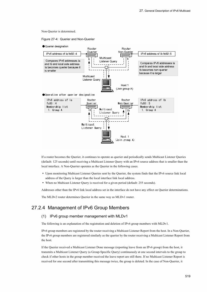
27. General Description of IPv6 Multicast
Non-Querier is determined.
Figure 27-4: Querier and Non-Querier
If a router becomes the Querier, it continues to operate as querier and periodically sends Multicast Listener Queries (default: 125 seconds) until receiving a Multicast Listener Query with an IPv6 source address that is smaller than the local interface. A Non-Querier operates as the Querier in the following cases.
• Upon monitoring Multicast Listener Queries sent by the Querier, the system finds that the IPv6 source link local address of the Query is larger than the local interface link local address.
• When no Multicast Listener Query is received for a given period (default: 255 seconds).
Addresses other than the IPv6 link local address set in the interface do not have any effect on Querier determinations.
The MLDv2 router determines Querier in the same way as MLDv1 router.
27.2.4 Management of IPv6 Group Members
(1) IPv6 group member management with MLDv1
The following is an explanation of the registration and deletion of IPv6 group members with MLDv1.
IPv6 group members are registered by the router receiving a Multicast Listener Report from the host. In a Non-Querier, the IPv6 group members are registered similarly as the querier by the router receiving a Multicast Listener Report from the host.
If the Querier received a Multicast Listener Done message (reporting leave from an IPv6 group) from the host, it transmits a Multicast Listener Query (a Group-Specific Query) continuously at one second intervals to the group to check if other hosts in the group member received the leave report are still there. If no Multicast Listener Report is received for one second after transmitting this message twice, the group is deleted. In the case of Non-Querier, it
519
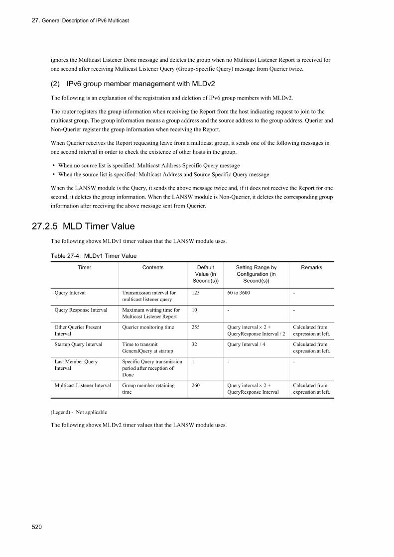
27. General Description of IPv6 Multicast
ignores the Multicast Listener Done message and deletes the group when no Multicast Listener Report is received for one second after receiving Multicast Listener Query (Group-Specific Query) message from Querier twice.
(2) IPv6 group member management with MLDv2
The following is an explanation of the registration and deletion of IPv6 group members with MLDv2.
The router registers the group information when receiving the Report from the host indicating request to join to the multicast group. The group information means a group address and the source address to the group address. Querier and Non-Querier register the group information when receiving the Report.
When Querier receives the Report requesting leave from a multicast group, it sends one of the following messages in one second interval in order to check the existence of other hosts in the group.
• When no source list is specified: Multicast Address Specific Query message• When the source list is specified: Multicast Address and Source Specific Query message
When the LANSW module is the Query, it sends the above message twice and, if it does not receive the Report for one second, it deletes the group information. When the LANSW module is Non-Querier, it deletes the corresponding group information after receiving the above message sent from Querier.
27.2.5 MLD Timer ValueThe following shows MLDv1 timer values that the LANSW module uses.
Table 27-4: MLDv1 Timer Value
(Legend) -: Not applicable
The following shows MLDv2 timer values that the LANSW module uses.
Timer Contents Default Value (in
Second(s))
Setting Range by Configuration (in
Second(s))
Remarks
Query Interval Transmission interval for multicast listener query
125 60 to 3600 -
Query Response Interval Maximum waiting time for Multicast Listener Report
10 - -
Other Querier Present Interval
Querier monitoring time 255 Query interval × 2 + QueryResponse Interval / 2
Calculated from expression at left.
Startup Query Interval Time to transmit GeneralQuery at startup
32 Query Interval / 4 Calculated from expression at left.
Last Member Query Interval
Specific Query transmission period after reception of Done
1 - -
Multicast Listener Interval Group member retaining time
260 Query interval × 2 + QueryResponse Interval
Calculated from expression at left.
520

27. General Description of IPv6 Multicast
Table 27-5: MLDv2 Timer Value
(Legend) -: Not applicable
27.2.6 Connection to MLDv1/MLDv2 SystemThe LANSW module supports MLDv1 and MLDv2. The MLD version to be used can be specified for each interface, using the configuration command ipv6 mld version. The table below shows the operation according to the specified version. The default is version 2.
Table 27-6: Operation for MLD Version Specified
(1) Connection to MLDv1/MLDv2 router
When multiple MLD routers exist on a single network (for example, in redundant configuration), the Querier is decided by receiving each other's Query (see "27.2.3 Querier Designation"). The LANSW module does not support the connection to MLDv1 router on the interface with MLD version 2 or version 2 only specified (in this case, V1 Query is ignored and Querier cannot be decided). When connecting to MLDv1 router, set the MLD version on the interface to version 1.
(2) Operation when MLDv1 and MLDv2 hosts coexist
When connecting to a network in which MLDv1 host and MLDv2 host coexist, use the MLD version of the interface in the default state. However, MLDv1 host must be able to receive MLDv2 Query as MLDv1 Query (RFC specifications).
When MLDv1/MLDv2 hosts coexist, the group members registration depends on the version of MLD requesting for
Timer Contents Default Value (in
Second(s))
Setting Range by Configuration (in
Second(s))
Remarks
Query Interval Transmission interval for multicast listener query
125 60 to 3600 -
Query Response Interval Maximum waiting time for Multicast Listener Report
10 - -
Other Querier Present Interval
Querier monitoring time 255 Query Interval × 2 + QueryResponse Interval / 2
Calculated from expression at left.
Startup Query Interval Time to transmit General Query at startup
30 Query Interval / 4 Calculated from expression at left.
Last Listener Query Interval
Specific Query transmission period after reception of separation request
1 - -
Multicast Address Listening Interval
Group member retaining time 260 Query Interval × 2 + Query Response Interval
Calculated from expression at left.
Older Version Host Present Interval
Transition period to MLDv2 multicast address compatible mode
260 Query Interval × 2 + Query Response Interval
Calculated from expression at left.
Specified Version Operation per Specified Version
version 1 Operates with MLDv1.Ignores MLDv2 packets.
version 2 Can operate with both MLDv1 and MLDv2.Operates with MLDv1 or MLDv2 by group address.
version 2 only Operates with MLDv2.Ignores MLDv1 packets.
521

27. General Description of IPv6 Multicast
joining the group, as shown in the table below.
Table 27-7: Group Member Registration When MLDv1/MLDv2 Hosts Coexist
27.2.7 Static Group JoinA static group join function is set to relay IPv6 multicast packets to the network in which the MLD-compatible host does not exist.
The interface in which static group join was set operates in the same manner as a group member even if it does not receive a Multicast Listener Report message.
As this is the MLDv1 function, it does not work if the MLD version of the corresponding interface is set to version 2 only. If it is set to version 2, it operates in the same way as the group join with MLDv1.
27.2.8 Notes on Using MLD• It takes 125 seconds (maximum) to create a (*,G) entry for a PIM-SM group and a (S,G) entry for a PIM-SSM group
when static group join is set by configuration.• When the LANSW module received MLDv2 Report with specified source to a group with address other than SSM
addresses set in the configuration, it forwards multicast packets to the group from all sources.
Group Join Request Group Member Registration
Receives with MLDv1 Registers the group member in MLDv1 mode.
Receives with MLDv2. Registers the group member in MLDv2 mode.
Receives with MLDv1 and MLDv2. Registers the group member in MLDv1 mode.
522

27. General Description of IPv6 Multicast
27.3 IPv6 Multicast Relay Function
Multicast packets are forwarded by hardware and software according to the multicast forwarding entry. The information of once forwarded IPv6 multicast packet is registered in the hardware IPv6 multicast forwarding entry. Registered IPv6 packets are forwarded by hardware. Unregistered IPv6 packets are forwarded according to IPv6 multicast forwarding entry created from software IPv6 multicast routing information. With the exception of restrictions on the addresses to be forwarded, the function has no particular difference to the IPv4 multicast forwarding function.
27.3.1 Address to Be ForwardedOut of the IPv6 multicast addresses, the node local, multicast address and the link local multicast address are not the subject of IPv6 multicast processing.
For details of IPv6 multicast addresses, see "15.1.5 Multicast Address".
27.3.2 Forwarding of IPv6 Multicast PacketIPv6 multicast packet forwarding is executed by hardware and software processing.
(1) Hardware forwarding process
The processing of IPv6 multicast packets by hardware is executed by the four procedures given below.
1. IPv6 multicast forwarding entry searchWhen a packet to an IPv6 multicast group is received, the relevant entry is searched from the hardware IPv6 multicast forwarding entries.
2. Multicast packet reception interface normality checkIf an entry is found in the search, it is checked to make sure that the IPv6 packet is received by the correct interface.
3. FilteringForwarding is performed according to the information registered in the IPv6 filtering table.
4. Hop limit based forwarding, and decrement of TTL valueWhether to forward or not is determined based on the hop limit value in a packet. If forwarding, the system decrements the hop limit value of the packet.
(2) Software forwarding process
The processing of IPv6 multicast packet forwarding by software differs in each of the cases indicated below.
• When there is no entry in hardware IPv6 multicast forwarding entriesWhen a packet from a source to an IPv6 multicast group is first received, the packet is forwarded by software according to the multicast forwarding entry created from IPv6 multicast route information. At the same time an IPv6 multicast forwarding entry is registered to the hardware.
• When IPv6 encapsulation is performedThe system temporarily encapsulates IPv6 packets and forwards them to rendezvous point. At the rendezvous point, the encapsulated packets are decapsulated and relayed to each destination.
(3) IPv6 multicast route information or IPv6 multicast forwarding entry search
The entry corresponding to the DA (destination group address) and SA (source address) of the received IPv6 multicast packet is searched from the IPv6 multicast route information or IPv6 multicast relay entry. The following figure shows how to search IPv6 multicast route information or IPv6 multicast forwarding entry.
523

27. General Description of IPv6 Multicast
Figure 27-5: Search Method of IPv6 Multicast Route Information or IPv6 Multicast Forwarding Entry
(4) Negative Cache
Negative cache is a function to discard multicast packets by hardware that cannot be forwarded. Negative cache is a forwarding entry without destination interface. When a multicast packets that cannot be forwarded is received, negative cache registers it to hardware. Then when a multicast packet with the same address as the registered multicast packet is received, that packet is discarded by hardware. This prevents increase in load when large volume of multicast packets that cannot be forwarded are received.
27.3.3 Notes on IPv6 multicast forwarding functionalityNote the following points when using the IPv6 multicast forwarding functionality.
• MTU length of the interface used in IPv6 multicastingIf the MTU length of the forwarding destination interface is shorter than that of the receiving interface, IPv6 multicast packets whose MTU length is longer than the forwarding destination interface cannot be forwarded properly. Make sure that the same MTU length value is used for all interfaces that are used in IPv6 multicasting.
524

27. General Description of IPv6 Multicast
27.4 IPv6 Route Control Function
The IPv6 multicast route control function creates IPv6 multicast route information and IPv6 multicast relay entry based on the neighbor information and group information collected using IPv6 multicast routing protocol.
27.4.1 Outline of IPv6 Multicast Routing ProtocolMulticast routing protocols are a route control protocols. The LANSW module supports the following multicast routing protocols: The format and setting of IPv6 PIM-SM frames forwarded by the LANSW module conform to RFC2362.
• PIM-SM (Protocol Independent Multicast-Sparse Mode)A protocol that performs multicast route control using unicast IPv6 route mechanism. Communication is performed via the shortest path after packets are transmitted to the rendezvous point.
• PIM-SSM (Protocol Independent Multicast-Source Specific Multicast)PIM-SSM is an extended PIM-SM function. Communication is performed via the shortest path without using any rendezvous point.
PIM-SM and PIM-SSM can operate simultaneously. However, PIM-SM and PIM-SSM cannot share the same group. If routers using PIM-SM and routers using PIM-DM coexist on the same network, no multicast packets are forwarded between the routers. To forward multicast packets between PIM-SM and PIM-SSM within the same network, configure to use the same multicast protocol on all routers.
27.4.2 IPv6 PIM-SMThe table below shows the support specifications of IPv6 PIM-SM messages. All messages support transmission and reception.
Table 27-8: IPv6 PIM-SM Message Support Specifications
The flow of IPv6 PIM-SM operation is as indicated below.
1. Each IPv6 PIM-SM router notifies the rendezvous point of the group information learned in the MLD.2. The rendezvous point identifies each group by receiving the group information from each IPv6 PIM-SM router.3. The IPv6 PIM-SM forms a delivery tree through the rendezvous point having the source at the root in order to first
distribute the multicast packets to all the group members from its source network via the rendezvous point.4. It decides the shortest path from the source by using the existing unicast routing so that each group can be reached
by the shortest path from the source (i.e., forms a shortest path delivery tree).5. The router starts multicast packet relay to each group member from the source via the shortest path.
The figure below shows the PIM-SM operation summary.
Type Function
PIM-Hello Detects the PIM neighboring router.
PIM-Join/Prune Joins in and prunes the multicast delivery tree.
PIM-Assert Determination of Forwarder
PIM-Register Encapsulates and forwards multicast packet to the rendezvous point.
PIM-Register-stop Suppresses the register message.
PIM-Bootstrap Decides the BSR. Also distributes rendezvous point information.
PIM-Candidate-RP-Advertisement The rendezvous point notifies the BSR of the rendezvous point information.
525

27. General Description of IPv6 Multicast
Figure 27-6: Outline of PIM-SM Operation
(1) Rendezvous point and bootstrap router (BSR)
Rendezvous point router and BSR are defined with configuration. The LANSW module can contain, rendezvous point and BSR in that is available one per system. However, it is possible that IPv4 PIM-SM and IPv6 PIM-SM can use separate routers to set the rendezvous point and BSR.
The BSR notifies all the multicast interfaces of the information on the rendezvous point (such as IPv6 address). This notification is performed hop by hop to all the PIM router link local multicast addresses (ff02::d). The figure below shows the rendezvous point and bootstrap router (BSR).
Figure 27-7: Rendezvous Point and Bootstrap Router (BSR)
The BSR (PIM-SM Router C) notifies all the multicast interfaces of the rendezvous point information. The router having received the rendezvous point information learns the IPv6 address at the rendezvous point, and notifies all the interfaces containing the IPv6 PIM router other than the received interface with the rendezvous point information.
(2) Notification of group join information to the rendezvous point
Each router notifies the rendezvous point of the group join information learned in the MLD. The source and destination IPv6 addresses of the notification are the system addresses of the corresponding routers. The rendezvous point identifies by each interface the existence of the IPv6 group by receiving the IPv6 group information. The figure below shows notification of group join information to the rendezvous point.
526

27. General Description of IPv6 Multicast
Figure 27-8: Notification of Group Join Information to the Rendezvous Point
First, each host joins Group 1 through MLD. PIM-SM Router D and PIM-SM Router E learn Group 1 information, and notify the rendezvous point (PIM-SM Router C) of Group 1 information. The rendezvous point (PIM-SM Router C) learns by receiving Group 1 information that Group 1 exists in the receiving interface.
(3) IPv6 multicast packet communication (encapsulation)
If the source server transmits an IPv6 multicast packet to Group 1, PIM-SM Router A transmits the IPv6 multicast packet to the rendezvous point (PIM-SM Router C) upon encapsulating the IPv6 (as a register packet). In the case of the LANSW module, the source and destination IPv6 addresses are the system addresses of corresponding routers (IPv6 address of rendezvous point has already been learned in "(1) Rendezvous point and bootstrap router (BSR)").
When the rendezvous point (PIM-SM Router C) receives the IPv6 encapsulated packet, it de-encapsulates the packet, and forwards the multicast packet addressed to Group 1 to the interface in which Group 1 exists (the existence of Group 1 has been learned in "(2) Notification of group join information to the rendezvous point"). When PIM-SM Router D and PIM-SM Router E receive the IPv6 multicast packets destined for Group 1, they forward the IPv6 multicast packets to the interface in which Group 1 exists (the existence of Group 1 has already been learned in "(2) Notification of group join information to the rendezvous point"). The figure below shows IPv6 multicast packet communication (Encapsulation) via rendezvous point.
Figure 27-9: IPv6 Multicast Packet Communication (Encapsulation)
(4) IPv6 multicast packet communication (decapsulation)
When the rendezvous point (PIM-SM Router C) receives an IPv6-encapsulated packet, it decapsulates the packet and forwards IPv6 multicast packet destined for Group 1 to the interface in which Group 1 exists (explained in "(3) IPv6 multicast packet communication (encapsulation)").
527

27. General Description of IPv6 Multicast
After this process, the rendezvous point reports the Group 1 information in the shortest route direction to the source server determined based on the existing IPv6 unicast routing information. The destination address used in this notification are all PIM router link local multicast address (ff02::d).
PIM-SM Router B and PIM-SM Router A received Group 1 information identify (learn) the existence of Group 1 in the receiving interface. PIM-SM Router A forwards the IPv6 multicast packet destined for Group 1 from the source to the corresponding interface, without making the IPv6 encapsulation. PIM-SM Router B, C, D and E forwards the packet to the interface in which Group 1 exists. The figure below shows IPv6 multicast packet communication (decapsulation) via rendezvous point.
Figure 27-10: IPv6 Multicast Packet Communication (Decapsulation)
(5) Multicast packet communication in shortest path
If PIM-SM Router D and E have received IPv6 multicast packets destined for Group 1 from the source (explained in "(4) IPv6 multicast packet communication (decapsulation)"), they notify Group 1 information in the direction of the shortest path toward the source (the existing IPv6 unicast routing information). The destination address used in this notification are all PIM router link local multicast address (ff02::d).
When PIM-SM router A received Group 1 information from PIM-SM Router D and E, it identifies the existence of Group 1 in the received interface, and when it received the IPv6 multicast packet destined for Group 1 from the source, it forwards the packet to the corresponding interface. The figure below shows multicast packet communication in the shortest path.
Figure 27-11: IPv6 Multicast Packet Communication via the Shortest Path
(6) Pruning of IPv6 multicast delivery tree
If the host left from Group 1 by MLD, PIM-DM Router D notifies the interface which reported Group 1 information of
528

27. General Description of IPv6 Multicast
the pruning information of Group 1. The destination address used in this notification are all PIM router link local multicast address (ff02::d).
When PIM-DM Router A receives the pruning notification for Group A, it stops the forwarding of the IPv6 multicast packet destined for Group A at the received interface. The figure below shows the pruning of IPv6 multicast delivery tree.
Figure 27-12: Pruning of IPv6 Multicast Delivery Tree
27.4.3 Neighbor DetectionThe IPv6 PIM router transmits the IPv6 PIM Hello message periodically to all the interfaces with which the IPv6 PIM made effective. The transmitted part of the PIM Hello message is destined for all PIM router link local multicast addresses (ff02::d). Neigboring IPv6 PIM routers are detected dynamically by receiving this message.This device supports the "Generation ID" option for the "PIM-Hello" message (complying with the RFC4601 and draft-ietf-pim-sm-bsr-07.txt files).
The Generation ID is a 32-bit random number assigned to each multicast interface and it is added at the time of sending the "PIM-Hello" message. The Generation ID is recreated each time the multicast interface goes Up. If the "Generation ID" option is added to the received "PIM-Hello" message, the Generation ID is saved and an interface fault in the neighboring devices is detected according to any change in the Generation ID. If a change in the Generation ID is detected, the neighboring device information updates and PIM-Hello, PIMBoostrap and PIM Join/Prune messages are transmitted without waiting regular advertisement timing.
This allows quick re-learning about the multicast channel information.
The PIM Hello message transmitted from the LANSW module includes the address list different to that of the link local address set in the source interface, as optional data of the PIM Hello message (type 65001). The LANSW module can find the addresses different to the link local addresses of the adjacent IPv6 PIM routers by receiving this optional data.
Also in the case where the next hop to IPv6 multicast sender S from the LANSW module is different to that of the link local address, the LANSW module can detect the IPv6 PIM router that reaches the sender by referring to this address list.
The figure below shows an example of how the adjacent PIM router receives the address.
529

27. General Description of IPv6 Multicast
Figure 27-13: Neighboring Router Address Reception by Using PIM Hello Message
27.4.4 Determination of ForwarderRedundant multicast packets may be forwarded to the network if multiple PIM-SM routers are connected in the same LAN.
When multiple PIM-SM router exist on the same LAN and two or more routers forward multicast packets to that LAN, the multicast route prefix and metric are compared using the PIM-Assert message and a router appropriate for the source network is selected as the forwarder.
Redundant multicast packet forwarding is prevented by having only the router selected as the forwarder forwarding multicast packets on that LAN.
The flow to determine the forwarder by PIM-Assert message is shown below.
1. Compare prefixes and select the router with smaller value as forwarder.2. If the prefixes are the same, compare metrics and select the router with smaller metric value as forwarder.3. If the metrics are the same, compare the IP address of each router and select the router with the larger IP address as
the forwarder.
The LANSW module sends PIM-Assert message with multicast route prefix fixed to 101 and metric fixed to 1024. However, PIM-Assert message with prefix fixed at 0 and metric fixed at 0 is sent when connecting directly with the source. Also, route distance and metric can be obtained from unicast information and sent as PIM-Assert message preference and metric by configuration.
The figure below shows the designation of the Forwarder.
530

27. General Description of IPv6 Multicast
Figure 27-14: Determination of Forwarder
27.4.5 DR Determination and OperationIf there are multiple IPv6 PIM-SM routers on the same LAN, the designated router (DR) on that LAN is determined. The DR is a router with the largest IPv6 link local address on that interface. The group join information from receiving host is notified to the rendezvous point by DR. The multicast packet sent by the source server is IPv6 encapsulated and sent to rendezvous point by DR. This action is shown in the figure below.
Figure 27-15: Operation of DR
The IPv6 address of PIM-SM Router A and PIM-SM Router B is compared, and if the IPv6 address of PIM-SM Router B is larger, PIM-SM Router B notifies the group join information to rendezvous point as DR. If the IPv6 address of PIM-SM Router E is larger when comparing PIM-SM Router D and E, PIM-SM Router E forward the IPv6 encapsulated packet to the rendezvous point as DR.
531

27. General Description of IPv6 Multicast
27.4.6 IPv6 PIM-SM Operation with MLDv2The following describes the IPv6 PIM-SM operation when multicast server (source address S1) sends multicast packet to multicast Group G1 used in PIM-SM and the host joins in the group by MLDv2.
1. An MLDv2 report (G1, S1) for joining in a multicast group is received from the host.2. The system that receives the MLDv2 report (G1, S1) sends PIM-Join containing the group address (G1) in the
shortest route direction to the rendezvous point.3. The rendezvous point that receives PIM-Join recognizes the existence of each group. The delivery tree with the
source as the root is formed to deliver multicast packets from the source network to each group member via the rendezvous point.
4. The shortest path from the source is determined by using the existing unicast routing so that the source can reach each group member can reach using the shortest path from the source (i.e., sends PIM-Join in the shortest route direction to the source and forms a shortest path delivery tree).
5. The system that receives the multicast packet sent by multicast delivery server S1 to Group G1 forwards the multicast packet according to the shortest path delivery tree.
Figure 27-16: Outline of IPv6 PIM-SM Operation with MLDv2
27.4.7 Notes on Using a Redundant RouteIn the case of a redundant configuration as shown in Figure 11-15, no IPv6 multicast packet is forwarded. Therefore, if a redundant route exists, setting of IPv6 PIM-SM is required in all the routers on that route.
532

27. General Description of IPv6 Multicast
Figure 27-17: Note on Redundant Route
27.4.8 IPv6 PIM-SM Timer SpecificationsThe table below shows the IPv6 PIM-SM timer value.
Table 27-9: IPv6 PIM-SM Timer
Timer Name Contents Default Value (in
Second(s))
Setting Range by Configuration (in Second(s))
Remarks
Hello-Period Hello interval 30 5 to 3600 -
Hello-Holdtime Neighbor adjacency hold time
105 3.5 × Hello-Period Calculated from expression at left.
Assert-Timeout Forwarding suppress interval due to assert
180 - -
Join/Prune-Period Join/prune transmission interval
60 30 to 3600 Up to +50% fluctuation.
Join/Prune-Holdtime Route information and forwarding interface hold time
210 3.5 × Join/Prune-Period
Calculated from expression at left.
Deletion-Delay-Time Multicast forwarding interface hold time after receiving prune
1/3 × Holding time contained in Prune received
0 to 300 *1
Data-Timeout Forwarding entry hold time
210 0 (indefinite),60 to 43200
Up to +90 second error.
Register-Supression-Timer
Encapsulated transmission suppression period
60 - There is up to ± 30 second fluctuation.
Probe-Time Time to send resume acknowledge for encapsulated transmission
5 5 to 60 With the default 5 seconds, an encapsulation transmission resume acknowledge (Null-Register) is sent once 5 seconds before the Register-Supression-Timer expires.*2
C-RP-Adv-Period Rendezvous point candidate advertise cycle
60 - -
RP-Holdtime Rendezvous point hold time
150 2.5 × C-RP-Adv-Period
Calculated from expression at left.
533
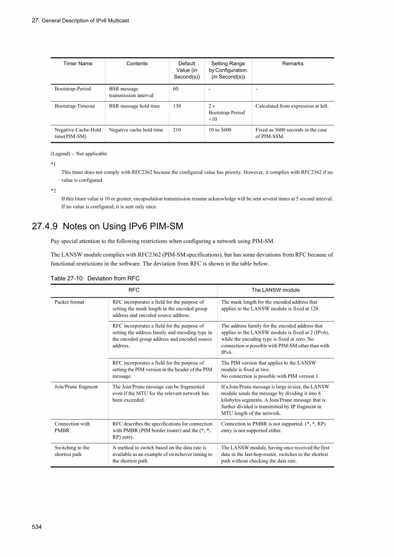
27. General Description of IPv6 Multicast
(Legend) -: Not applicable
*1This timer does not comply with RFC2362 because the configured value has priority. However, it complies with RFC2362 if no value is configured.
*2If this timer value is 10 or greater, encapsulation transmission resume acknowledge will be sent several times at 5 second interval. If no value is configured, it is sent only once.
27.4.9 Notes on Using IPv6 PIM-SMPay special attention to the following restrictions when configuring a network using PIM-SM.
The LANSW module complies with RFC2362 (PIM-SM specifications), but has some deviations from RFC because of functional restrictions in the software. The deviation from RFC is shown in the table below.
Table 27-10: Deviation from RFC
Bootstrap-Period BSR message transmission interval
60 - -
Bootstrap-Timeout BSR message hold time 130 2 × Bootstrap-Period+10
Calculated from expression at left.
Negative-Cache-Holdtime(PIM-SM)
Negative cache hold time 210 10 to 3600 Fixed as 3600 seconds in the case of PIM-SSM.
RFC The LANSW module
Packet format RFC incorporates a field for the purpose of setting the mask length in the encoded group address and encoded source address.
The mask length for the encoded address that applies to the LANSW module is fixed at 128.
RFC incorporates a field for the purpose of setting the address family and encoding type in the encoded group address and encoded source address.
The address family for the encoded address that applies to the LANSW module is fixed at 2 (IPv6), while the encoding type is fixed at zero. No connection is possible with PIM-SM other than with IPv6.
RFC incorporates a field for the purpose of setting the PIM version in the header of the PIM message.
The PIM version that applies to the LANSW module is fixed at two.No connection is possible with PIM version 1.
Join/Prune fragment The Join/Prune message can be fragmented even if the MTU for the relevant network has been exceeded.
If a Join/Prune message is large in size, the LANSW module sends the message by dividing it into 8 kilobytes segments. A Join/Prune message that is further divided is transmitted by IP fragment in MTU length of the network.
Connection with PMBR
RFC describes the specifications for connection with PMBR (PIM border router) and the (*, *, RP) entry.
Connection to PMBR is not supported. (*, *, RP) entry is not supported either.
Switching to the shortest path
A method to switch based on the data rate is available as an example of switchover timing to the shortest path.
The LANSW module, having once received the first data in the last-hop-router, switches to the shortest path without checking the data rate.
Timer Name Contents Default Value (in
Second(s))
Setting Range by Configuration (in Second(s))
Remarks
534

27. General Description of IPv6 Multicast
27.4.10 IPv6 PIM-SSMPIM-SSM is an extended PIM-SM function. PIM-SM and PIM-SSM can operate simultaneously. The multicast address that PIM-SSM uses is assigned using IANA. In the LANSW module, the range of multicast address (group address) in which PIM-SSM operates can be specified in the configuration. PIM-SM operates in those other than the specified address.
PIM-SM requires a multicast forwarding packet during multicast entry creation. PIM-SSM creates an IPv6 multicast forwarding entry by exchanging multicast route information (PIM-Join) and forwards multicast packet with the corresponding entry. PIM-SSM does not require a rendezvous point and bootstrap router. Therefore, the encapsulation and decapsulation of packet are not required when a multicast packet is relayed. This enables a highly-efficient multicast forwarding. Moreover, the LANSW module supplies the means by which PIM-SSM can be operated in MLD.
(1) Support specifications of IPv6 PIM-SSM message
These are the same as the support specifications of PIM-SM message.
(2) Preconditions for operating IPv6 PIM-SSM
The setting below is required for the LANSW module's configuration.
• Setting of each systemSet the group address range in which PIM-SSM operates.
• System to which the host running MLD is directly connected.Set the group address and source address in which PIM-SSM operates to receive MLD.
(3) IPv6 PIM-SSM operation with MLDv1
The information on the source is required to use PIM-SSM. When MLDv1 is used with the LANSW module, setting the source on the configuration enables PIM-SSM.
The IPv6 PIM-SSM operation when the multicast server (source address S1) transmits a multicast packet to multicast group G1 is as follows.
1. An MLD Report (G1) for joining in a multicast group is received from the host.2. The system that received the MLD report compares the group address (G1) notified by the report and the group
address defined in the configuration. When the group addresses match, PIM-Join is transmitted in the shortest route direction (determined using unicast routing information) to the source address (S1) defined in the configuration. In this case, the source address (S1) and group address (G1) information is written in the PIM-Join. Each system that receives PIM-Join transmits them in the shortest route direction to source address (S1) hop-by-hop. The system that receives PIM-Join learns the IPv6 multicast routing information of a single source address (S1) and group address (G1).
C-RP-Adv reception and bootstrap transmission
A bootstrap message is allowed to be fragmented when the produced message length exceeds the maximum packet length. However, in order to suppress fragmentation, it is recommended that you set the maximum number of the rendezvous point candidate.
The LANSW module only uses one rendezvous point and BSR in the system. Furthermore, the maximum number of group prefixes that can be set by the rendezvous point is 128.If the bootstrap message is large in size, the LANSW module transmits the message upon IP-fragmenting it in the MTU length of the network.
Hello message option HoldTime option (type 1) is defined in RFC. The LANSW module uses a neighboring router address list option (type 65001) in addition to the HoldTime option. (Refer to "27.4.3 Neighbor Detection").
RFC The LANSW module
535

27. General Description of IPv6 Multicast
3. Multicast server (S1) transmits a multicast packet to Group 1 (G1). The system receiving multicast packets forwards the packets according to IPv6 multicast forwarding entry created from the learned IPv6 multicast route information.
The outline of PIM-SSM operation is shown in the figure below.
Figure 27-18: Outline of PIM-SSM Operation
(4) IPv6 PIM-SSM operation with MLDv2
The information on the source is required to use PIM-SSM. MLDv2 can be used with PIM-SSM by specifying the source in the report message.
The IPv6 PIM-SSM operation when the multicast server (source address S1) transmits a multicast packet to multicast group G1 is as follows.
1. An MLDv2 report (G1, S1) for joining in a multicast group is received from the host.2. The system that receives the MLDv2 report (G1, S1) transmits PIM-Join containing the group address (G1) and
source address (S1) in the report.3. Each system that receives PIM-Join transmits PIM-Join in the shortest route direction to source address (S1)
hop-by-hop. Each system that receives PIM-Join forms a delivery tree to forward the multicast packet from the source address S1 only to the interface that received PIM-Join.
4. The system that receives the multicast packet sent by Multicast server S1 to Group G1 forwards the multicast packet according to the multicast forwarding information.
536

27. General Description of IPv6 Multicast
Figure 27-19: Outline of IPv6 PIM-SSM Operation with MLDv2
(5) IPv6 route control when MLDv1/MLDv2 hosts coexist
The following describes the IPv6 route control operation when MLDv1 is set to be used with PIM-SSM while MLDv1 and MLDv2 hosts coexist.
When the join request for the group address within the PIM -SSM target address range set on the configuration, PIM-SSM operates as described in the following table. When the join request is received by MLDv1 report, the source address set in the configuration is used as the source list. When receiving join request to the same group address in both MLDv1 Report and MLDv2 Report (EXCLUDE), a combination of the source address specified in the configuration and source list contained in the MLDv2 Report (INCLUDE) is used as the source list.
Table 27-11: IPv6 Route Control Operation When MLDv1/MLDv2 Hosts Coexist
(6) Neighbor detection
Same as PIM-SM ("27.4.3 Neighbor Detection").
Join Group Address MLDv1 ReportMLDv2 Report (EXCLUDE)
MLDv2 Report (INCLUDE)
Within the SSM address range PIM-SSM PIM-SSM
Out of the SSM address range PIM-SM PIM-SM
537

27. General Description of IPv6 Multicast
(7) Determination of Forwarder
Same as PIM-SM ("27.4.4 Determination of Forwarder").
(8) DR determination and operation
Same as PIM-SM ("27.4.5 DR Determination and Operation").
(9) Note on redundant route
Same as PIM-SM ("27.4.7 Notes on Using a Redundant Route").
538

27. General Description of IPv6 Multicast
27.5 Network Design Concept
27.5.1 IPv6 Multicast RelayPay attention to the following when forwarding IPv6 multicast packets using the LANSW module.
(1) Common to IPv6 PIM-SM and IPv6 PIM-SSM
(a) Relay interruption due to restarting of routing program
Note that IPv6 multicast communication is interrupted until the system relearns IPv6 multicast routing information when IPv6 multicast routing program restarts with restart ipv6-multicast command.
(b) Point-to-point line
Specify (gateway-specify) the connection destination address explicitly when performing IPv6 multicast communication using a point-to-point line in which a unicast static route is set.
(c) Packet passing by timing
If the system receives multicast data from a sender and PIM-Join message from a receiver at the same time, some packets may be passed, resulting in the change of packet order, depending on the timing.
(2) IPv6 PIM-SM
When PIM-SM is used with IPv6, pay attention to the following aspects.
(a) Packet loss by software relay processing
The LANSW module sets a multicast forwarding entry to the hardware for performing IPv6 multicast communication at first IPv6 multicast packet reception. Packets may be temporarily lost (except for PIM-SSM) because multicast packets are relayed by software until an entry is created.
(b) Packet passing at switching over of the hardware relay
On the LANSW module, when setting of IPv6 multicast forwarding entry in hardware completes, the software relaying of PIv6 multicast packets performed up to that point is taken over by hardware. When switching, some packets may be passed, resulting in the change of packet order.
(c) Double-relay or packet loss by path switchover
The LANSW module may temporarily double-relay or lose packets when relaying IPv6 multicast packets via a rendezvous point or when switching them from via rendezvous point to via shortest path.
For relaying operation of IPv6 multicast packets via rendezvous-point and switching operation from via rendezvous-point to via shortest path, see "27.4.2 IPv6 PIM-SM".
(d) System address setting required
When the LANSW module is used as a first-hop-router or last-hop-router, an IPv6 address set with a local address of the system management information is employed in the communication to the rendezvous point. For this reason, it is mandatory to set a system address with IPv6 PIM-SM, even if it is not a rendezvous point or BSR, unlike with IPv4 PIM-SM.
(e) Reachability of system address
When the LANSW module is used as a rendezvous point or bootstrap router, the IPv6 address set with a local address of the system management information serves as the address of the rendezvous point or bootstrap router. This local
539

27. General Description of IPv6 Multicast
address of the system management information must be available to all the systems operating IPv6 multicast communication for unicast route detection and communication.
(f) Static rendezvous point
Static rendezvous point is a function to specify rendezvous point without using BSR. Static rendezvous point is set with configuration.
Static rendezvous point can also coexist with rendezvous candidate advertised from BSR with Bootstrap message. When coexisting, a static rendezvous point has priority over rendezvous candidate advertised from BSR with Bootstrap message.
A rendezvous point candidate router operates as a rendezvous point when it recognizes its own address as the rendezvous point. Therefore, it is necessary even for the rendezvous point candidate router to set the static rendezvous point when designing a network using a static rendezvous point without using BSR.
Also, when using static rendezvous point, the same setting must be used on all routers on the same network.
27.5.2 Redundant Route (Route Switchover Due to Failure)When an IPv6 multicast route is structured in a redundant configuration through the LANSW module, pay attention to the following aspects.
(1) Use of IPv6 PIM-SM
In the case of IPv6 PIM-SM, keep in mind that it will take some time for IPv6 multicast communication to resume in the route switching described below.
• When a redundant route is switched, it may take the time described below until communication restarts. Time for switching the network information (unicast routing information) of the relevant multicast packet source+ 20 seconds
• When a rendezvous point or BSR has been switched to other system (when a rendezvous point or BSR is switched to another system due to a fault or configuration change), it may take the maximum of 340 seconds + membership notification time for the communication to resume.
• When DR has been switched to another system, it may take a maximum of 240 seconds + membership notification time for the communication to resume.
When a redundant route is switched due to a fault, as well as when a route has been changed intentionally for the purposes of configuration change, the IPv6 multicast communication may be stopped for the above time periods. Execute system configuration changes on a well-planned basis.
Especially, when a rendezvous point or BSR is switched to another system, make settings such that the priority values in the configuration of the new rendezvous point or BSR will as a result be higher than those of the old rendezvous point or BSR.
(2) Use of IPv6 PIM-SSM
When a redundant route is switched, it may take the time described below until communication restarts.
Time for switching the network information (unicast routing information) of the relevant multicast packet source+20 seconds
540
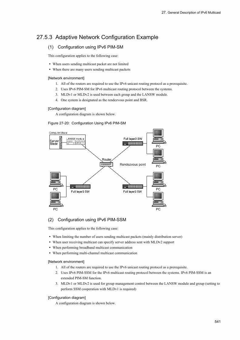
27. General Description of IPv6 Multicast
27.5.3 Adaptive Network Configuration Example
(1) Configuration using IPv6 PIM-SM
This configuration applies to the following case:
• When users sending multicast packet are not limited• When there are many users sending multicast packets
[Network environment]1. All of the routers are required to use the IPv6 unicast routing protocol as a prerequisite.2. Uses IPv6 PIM-SM for IPv6 multicast routing protocol between the systems.3. MLDv1 or MLDv2 is used between each group and the LANSW module.4. One system is designated as the rendezvous point and BSR.
[Configuration diagram]A configuration diagram is shown below.
Figure 27-20: Configuration Using IPv6 PIM-SM
(2) Configuration using IPv6 PIM-SSM
This configuration applies to the following case:
• When limiting the number of users sending multicast packets (mainly distribution server)• When user receiving multicast can specify server address sent with MLDv2 support• When performing broadband multicast communication• When performing multi-channel multicast communication
[Network environment]1. All of the routers are required to use the IPv6 unicast routing protocol as a prerequisite.2. Uses IPv6 PIM-SSM for the IPv6 multicast routing protocol between the systems. IPv6 PIM-SSM is an
extended PIM-SM function.3. MLDv1 or MLDv2 is used for group management control between the LANSW module and group (setting to
perform SSM cooperation with MLDv1 is required)
[Configuration diagram]A configuration diagram is shown below.
541

27. General Description of IPv6 Multicast
Figure 27-21: Configuration Using IPv6 PIM-SSM
27.5.4 Notes on Network ConfigurationIPv6 multicast is suitable for one-way communication of 1 (sender): N (receiver) that distributes data from the server (sender) to each group (receiver). Recommended network configuration and notes for IPv6 multicast are as follows.
(1) Common to IPv6 PIM-SM and IPv6 PIM-SSM
(a) Compatible configuration
For IPv6 PIM-SM or IPv6 PIM-SSM (abbreviated as PIM, hereafter), PIM must be set on every router in the entire path from a sender to receiver. If the path has any router which does not have PIM setting, multicast packets cannot be relayed. When a neighbor router does not have PIM setting, specifying the upstream port allows packet relay.
"Figure 27-22: Example of Specifying the IPv6 Upstream Port" shows an example of specifying the upstream port. Since the multicast domains that Router A and the LANSW module belong to are different, PIM is not set between them. However, there is a request to transmit multicast data from the sender in Domain X to the receiver in Domain Y. Because PIM is not operating between Router A and the LANSW module, the multicast data sent from the sender S is discarded in the LANSW module. If the upstream port to the sender S is specified on the port alpha in the LANSW module, multicast packets can be transferred to Domain Y.
542

27. General Description of IPv6 Multicast
Figure 27-22: Example of Specifying the IPv6 Upstream Port
Specification of upstream port is applied to the configuration as shown above, the multicast packet relay may not be possible for other configurations.
(b) Configuration that requires caution
Pay attention when using an IPv6 PIM-SM or IPv6 PIM-SSM router in the configuration described below.
Be sure to operate PIM-SM for the interface in which multiple routers directly connected with the host exist in the same network, as in the configuration described below.Multicast data may be double-relayed when only MLD is operated without operating PIM-SM for the interface in which multiple routers exist in the same network.
The next figure shows an environment where the LANSW module has static routes to Router A and B with a gateway (virtual interface) operating VRRP. In this configuration PIM protocol cannot detect a upstream router thus multicast communication is not possible (so is PIM-SSM).To realize multicast communication in this configuration, you have to set the LANSW module a rendezvous point address, BSR address and static routes having real address of Router A or B as the gateway address to the multicast data source.
543
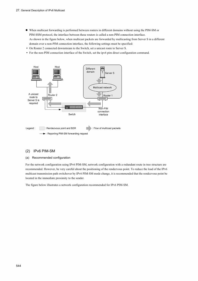
27. General Description of IPv6 Multicast
When multicast forwarding is performed between routers in different domains without using the PIM-SM or PIM-SSM protocol, the interface between these routers is called a non-PIM connection interface.As shown in the figure below, when multicast packets are forwarded by multicasting from Server S in a different domain over a non-PIM connection interface, the following settings must be specified:
• On Router 2 connected downstream to the Switch, set a unicast route to Server S.• For the non-PIM connection interface of the Switch, set the ipv6 pim direct configuration command.
(2) IPv6 PIM-SM
(a) Recommended configuration
For the network configuration using IPv6 PIM-SM, network configuration with a redundant route in tree structure are recommended. However, be very careful about the positioning of the rendezvous point. To reduce the load of the IPv6 multicast transmission path switchover by IPv6 PIM-SM mode change, it is recommended that the rendezvous point be located in the immediate proximity to the sender.
The figure below illustrates a network configuration recommended for IPv6 PIM-SM.
544
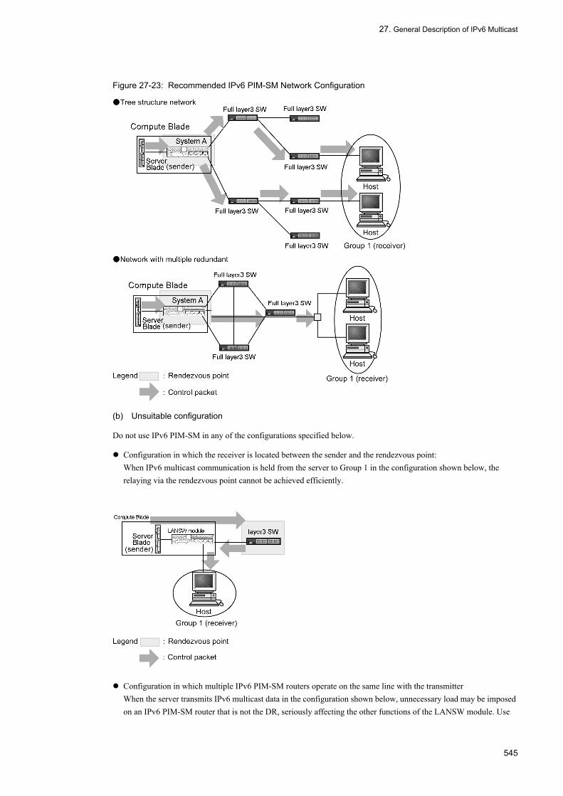
27. General Description of IPv6 Multicast
Figure 27-23: Recommended IPv6 PIM-SM Network Configuration
(b) Unsuitable configuration
Do not use IPv6 PIM-SM in any of the configurations specified below.
Configuration in which the receiver is located between the sender and the rendezvous point:When IPv6 multicast communication is held from the server to Group 1 in the configuration shown below, the relaying via the rendezvous point cannot be achieved efficiently.
Configuration in which multiple IPv6 PIM-SM routers operate on the same line with the transmitterWhen the server transmits IPv6 multicast data in the configuration shown below, unnecessary load may be imposed on an IPv6 PIM-SM router that is not the DR, seriously affecting the other functions of the LANSW module. Use
545

27. General Description of IPv6 Multicast
separate lines for Systems A and B.
Configuration in which multiple IPv6 PIM-SM routers are operating on the same line with the IPv6 multicast groups (receivers) and an IPv6 PIM-SM router not connected to the rendezvous point existsWhen IPv6 multicast communication is held to Group 1 in the configuration shown below, the shortest path may not be established between the sender and Group 1.Router A and Router B should be connected to the rendezvous point without going through Router B and Router A, respectively.
Configuration without presence of receiverWhen the server transmits a large volume of IPv6 multicast data in the configuration shown below, the LANSW module is subjected to a heavy load arising from data discard processing, and its other functions may be seriously affected. For this reason, when IPv6 multicast is used, operate the router by setting up at least one receiver.
(3) IPv6 PIM-SSM
(a) Configuration that requires caution
When IPv6 PIM-SSM is used in the configuration shown below, due caution must be exerted.
Configuration in which multiple IPv6 PIM-SSM routers operate on the same line with IPv6 multicast groups (receivers)When PIM-SSM is operated with MLDv1 in the configuration shown below, set configuration commands ipv6 pim
546
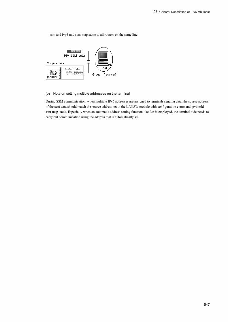
27. General Description of IPv6 Multicast
ssm and ivp6 mld ssm-map static to all routers on the same line.
(b) Note on setting multiple addresses on the terminal
During SSM communication, when multiple IPv6 addresses are assigned to terminals sending data, the source address of the sent data should match the source address set to the LANSW module with configuration command ipv6 mld ssm-map static. Especially when an automatic address setting function like RA is employed, the terminal side needs to carry out communication using the address that is automatically set.
547

27. General Description of IPv6 Multicast
548

28. Configuration and Operation of IPv6 Multicast
28Configuration and Operation of IPv6 MulticastThis chapter describes how to set and verify the IPv6 multicast configuration.
28.1 Configuration
28.2 Operation
549
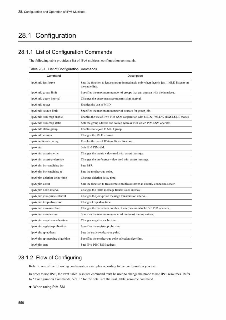
28. Configuration and Operation of IPv6 Multicast
28.1 Configuration
28.1.1 List of Configuration CommandsThe following table provides a list of IPv6 multicast configuration commands.
Table 28-1: List of Configuration Commands
28.1.2 Flow of ConfiguringRefer to one of the following configuration examples according to the configuration you use.
In order to use IPv6, the swrt_table_resource command must be used to change the mode to use IPv6 resources. Refer to " Configuration Commands, Vol. 1" for the details of the swrt_table_resource command.
When using PIM-SM
Command Description
ipv6 mld fast-leave Sets the function to leave a group immediately only when there is just 1 MLD listener on the same link.
ipv6 mld group-limit Specifies the maximum number of groups that can operate with the interface.
ipv6 mld query-interval Changes the query message transmission interval.
ipv6 mld router Enables the use of MLD.
ipv6 mld source-limit Specifies the maximum number of sources for group join.
ipv6 mld ssm-map enable Enables the use of IPv6 PIM-SSM cooperation with MLDv1/MLDv2 (EXCLUDE mode).
ipv6 mld ssm-map static Sets the group address and source address with which PIM-SSM operates.
ipv6 mld static-group Enables static join to MLD group.
ipv6 mld version Changes the MLD version.
ipv6 multicast-routing Enables the use of IPv6 multicast function.
ipv6 pim Sets IPv6 PIM-SM.
ipv6 pim assert-metric Changes the metric value used with assert message.
ipv6 pim assert-preference Changes the preference value used with assert message.
ipv6 pim bsr candidate bsr Sets BSR.
ipv6 pim bsr candidate rp Sets the rendezvous point.
ipv6 pim deletion-delay-time Changes deletion delay time.
ipv6 pim direct Sets the function to treat remote multicast server as directly-connected server.
ipv6 pim hello-interval Changes the Hello message transmission interval.
ipv6 pim join-prune-interval Changes the join/prune message transmission interval.
ipv6 pim keep-alive-time Changes keep alive time.
ipv6 pim max-interface Changes the maximum number of interface on which IPv6 PIM operates.
ipv6 pim mroute-limit Specifies the maximum number of multicast routing entries.
ipv6 pim negative-cache-time Changes negative cache time.
ipv6 pim register-probe-time Specifies the register probe time.
ipv6 pim rp-address Sets the static rendezvous point.
ipv6 pim rp-mapping-algorithm Specifies the rendezvous point selection algorithm.
ipv6 pim ssm Sets IPv6 PIM-SSM address.
550

28. Configuration and Operation of IPv6 Multicast
• Setting IPv6 multicast routing• Setting IPv6 PIM-SM• Setting rendezvous point (using local system as rendezvous point)• Setting BSR (using local system as BSR)
When using PIM-SM (static rendezvous point)• Setting IPv6 multicast routing• Setting IPv6 PIM-SM• Setting rendezvous point (using local system as rendezvous point)• Setting static rendezvous point
When using PIM-SSM• Setting IPv6 multicast routing• Setting IPv6 PIM-SM• Setting IPv6 PIM-SSM• Setting MLD
28.1.3 Setting IPv6 Multicast Routing[Point of setting]
In order to use IPv6 multicast routing on the LANSW module, an address must be set on loopback 0 interface as loopback address of the LANSW module and the following must be set in global configuration mode. An example of setting the loopback address of the LANSW module to 2001:db8::b is shown.
[Setup using commands]
1. (config)# interface loopback 0
(config-if)# ipv6 address 2001:db8::b
(config-if)# exit
Sets the loopback address.
2. (config)# ipv6 multicast-routing
Enables the use of IPv6 multicast function.
28.1.4 Setting IPv6 PIM-SM[Point of setting]
IPv6 PIM-SM (sparse mode) must be set for interface which uses IPv6 multicast routing. IPv6 PIM-SM (sparse mode) is configured in interface configuration mode. An example of setting the IPv6 address of the interface to 2001:db8::a/16 is shown.
[Setup using commands]
1. (config)# interface vlan 10
(config-if)# ipv6 address 2001:db8::a/16
(config-if)# ipv6 enable
Sets IPv6 address.
2. (config-if)# ipv6 pim
Specifies to operate as IPv6 PIM-SM (sparse mode).
551

28. Configuration and Operation of IPv6 Multicast
28.1.5 Setting IPv6 PIM-SM Rendezvous Point Related Items
(1) Setting rendezvous point
[Point of setting]When using the LANSW module as rendezvous point, set the following in global configuration mode. Use the address set on loopback 0 interface as the rendezvous point address. An example of setting the loopback address of the LANSW module to 2001:db8::b and the managed multicast group address to ff15::/16 is shown.
[Setup using commands]
1. (config)# ipv6 access-list GROUP1
(config-ipv6-acl)# permit ipv6 ff15::/16 any
(config-ipv6-acl)# exit
Creates an access list of managed multicast group addresses.
2. (config)# ipv6 pim bsr candidate rp 2001:db8::b group-list GROUP1
Sets the LANSW module as rendezvous point candidate (specifies access list created in step 1 as managed multicast group address).
(2) Setting BSR
[Point of setting]When using the LANSW module as BSR, set the following in global configuration mode. Use the address set on loopback 0 interface as the BSR address. An example of setting the loopback address of the LANSW module to 2001:db8::b is shown.
[Setup using commands]
1. (config)# ipv6 pim bsr candidate bsr 2001:db8::b
Sets the LANSW module as a BSR candidate.
(3) Setting static rendezvous point
[Point of setting]When specifying static rendezvous point, set the following in global configuration mode. An example of setting the address of static rendezvous point system to 2001:db8::b is shown.
[Setup using commands]
1. (config)# ipv6 pim rp-address 2001:db8::b
Specifies 2001:db8::b as rendezvous point.
28.1.6 Setting IPv6 PIM-SSM
(1) IPv6 PIM-SSM address setting
[Point of setting]Set the following in global configuration mode when using IPv6 PIM-SSM on the LANSW module. IPv6 PIM-SSM operates on the specified SSM address range on interface set with IPv6 PIM-SM with this setting. Only one SSM address can be set with the LANSW module. An example of setting the SSM address range on which PIM-SSM operates to ff35::/16 is shown.
552

28. Configuration and Operation of IPv6 Multicast
[Setup using commands]
1. (config)# ipv6 access-list GROUP2
(config-ipv6-acl)# permit ipv6 ff35::/16 any
(config-ipv6-acl)# exit
Creates an access list of SSM address range.
2. (config)# ipv6 pim ssm range GROUP2
Enables the use of IPv6 PIM-SSM (specify the access list created in step 1 for SSM address range).
(2) Setting to enable IPv6 PIM-SSM with MLDv1/MLDv2 (EXCLUDE mode)
[Point of setting]PIM-SSM cooperation is disabled with MLDv1/MLDv2 (EXCLUDE mode) because the source address cannot be specified. The LANSW module performs cooperation to PIM-SSM by setting the group address and source address for PIM-SSM. A PIM-SSM configuration example with source address of server 1 set to 2001:db8::aa:1 and server 2 set to 2001:db8::bb:1 when group address is ff35::1 and two servers are used is shown.
Figure 28-1: PIM-SSM Configuration Example
[Setup using commands]
1. (config)# ipv6 access-list GROUP3
(config-ipv6-acl)# permit ipv6 host ff35::1 any
(config-ipv6-acl)# exit
Creates access list specifying group address.
2. (config)# ipv6 mld ssm-map static GROUP3 2001:db8::aa:1
(config)# ipv6 mld ssm-map static GROUP3 2001:db8::bb:1
Sets the group address for PIM-SSM and source address for servers 1 and 2 (specify access list created in step 1 as group address).
3. (config)# ipv6 mld ssm-map enable
Enables use of IPv6 PIM-SSM.
553

28. Configuration and Operation of IPv6 Multicast
28.1.7 Setting MLD[Point of setting]
Set as follows to use MLD on interface with IPv6 PIM-SM set.
[Setup using commands]
1. (config-if)# ipv6 mld router
Specifies to use MLD version 1, 2 mixed mode (default) on the relevant interface.
554

28. Configuration and Operation of IPv6 Multicast
28.2 Operation
28.2.1 List of Operation CommandsThe following table provides a list of IPv6 multicast operation commands.
Table 28-2: List of Operation Commands
28.2.2 Checking IPv6 Multicast Group Address RouteIf IPv6 multicast routing information is set on the LANSW module, execute the show ipv6 mcache command and the show netstat multicast command and make sure that the route to the destination address exists. If no route exists and downstream is not correct, refer to "28.2.3 Checking IPv6 PIM-SM Information" and "28.2.4 Checking MLD Information".
The show ipv6 mcache command displays the IPv6 multicast routing cache retained by the IPv6 multicast routing daemon, while the netstat multicast command displays the multicast relay entry.
The show netstat multicast command displays the negative cache (packet discarding entry for which no output interface exists) as well.
Command Description
show ipv6 mcache Lists all multicast routes.
show ipv6 mroute Displays PIM-SM multicast route information.
show ipv6 pim interface Displays state of IPv6 PIM-SM/SSM interface.
show ipv6 pim neighbor Displays neighbor information of IPv6 PIM-SM/SSM interface.
show ipv6 pim mcache The IPv6 PIM-SM or PIM-SSM multicast relay entry is displayed.
show ipv6 pim bsr Displays IPv6 PIM-SM/SSM BSR information.
show ipv6 pim rp-mapping Displays IPv6 PIM-SM rendezvous point information.
show ipv6 pim rp-hash The IPv6 PIM-SM rendezvous point information for each group is displayed.
show ipv6 mld interface Displays state of MLD interface information.
show ipv6 mld group Displays MLD information.
show ipv6 rpf Displays RPF information of PIM.
show ipv6 multicast statistics The statistic information about the IPv6 multicast is displayed.
clear ipv6 multicast statistics The statistic information about the "clear ip multicast statistics IPv6" multicast is cleared.
restart ipv6-multicast Restarts the IPv6 multicast routing program.
debug protocols ipv6-multicast Outputs syslog of event trace information output by IPv6 multicast routing program.
no debug protocols ipv6-multicast Stops output of syslog of event trace information output by IPv6 multicast routing program.
dump protocols ipv6-multicast Collects the dump of the control-table and event-trace information collected by the IPv6 multicast routing program.
erase protocol-dump ipv6-multicast Deletes the event trace information file created by the multicast routing program, the control table information file, and the core file dump.
555

28. Configuration and Operation of IPv6 Multicast
Figure 28-2: Execution Result of show ipv6 mcache Command
> show ipv6 mcacheDate 2005/08/01 15:20:00 UTCTotal: 1 routeGroup Address Source Addressff15::2 2001:db8::100 Uptime: 00:20 Expires: 02:40 upstream: VLAN0002 downstream: VLAN0001 VLAN0003>
Figure 28-3: Execution Result of show netstat multicast Command
> show netstat multicastDate 2005/08/01 15:20:00 UTCVirtual Interface Table is empty Multicast Forwarding Cache is empty IPv6 Virtual Interface Table Mif Rate PhyIF Pkts-In Pkts-Out 0 0 VLAN0004 0 0 1 0 VLAN0002 0 0 2 0 VLAN0001 0 0 3 0 VLAN0003 0 0 IPv6 Multicast Forwarding Cache Origin Group Packets Waits In-Mif Out-Mifs 2001:db8::100 ff15::2 0 0 1 2 3 Total no. of entries in cache: 1
28.2.3 Checking IPv6 PIM-SM InformationThe check items for when the PIM-SM function is set in the IPv6 multicast routing information on the LANSW module are as follows:
556
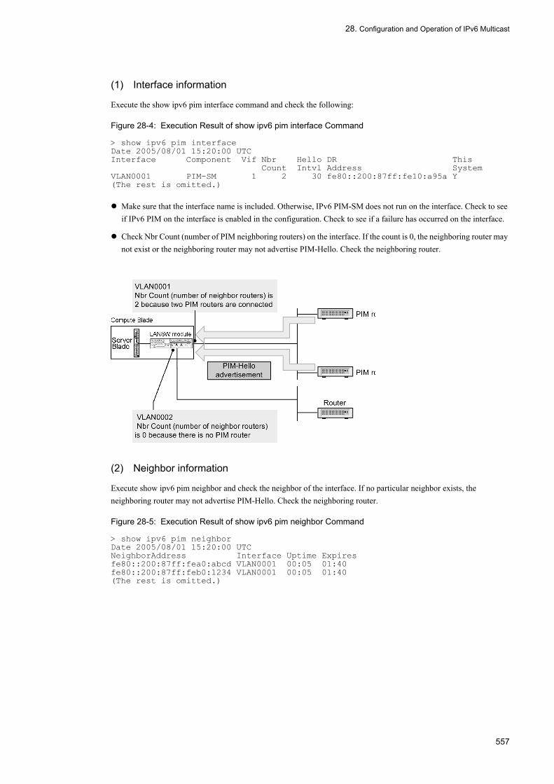
28. Configuration and Operation of IPv6 Multicast
(1) Interface information
Execute the show ipv6 pim interface command and check the following:
Figure 28-4: Execution Result of show ipv6 pim interface Command
> show ipv6 pim interfaceDate 2005/08/01 15:20:00 UTCInterface Component Vif Nbr Hello DR This Count Intvl Address SystemVLAN0001 PIM-SM 1 2 30 fe80::200:87ff:fe10:a95a Y(The rest is omitted.)
Make sure that the interface name is included. Otherwise, IPv6 PIM-SM does not run on the interface. Check to see if IPv6 PIM on the interface is enabled in the configuration. Check to see if a failure has occurred on the interface.
Check Nbr Count (number of PIM neighboring routers) on the interface. If the count is 0, the neighboring router may not exist or the neighboring router may not advertise PIM-Hello. Check the neighboring router.
(2) Neighbor information
Execute show ipv6 pim neighbor and check the neighbor of the interface. If no particular neighbor exists, the neighboring router may not advertise PIM-Hello. Check the neighboring router.
Figure 28-5: Execution Result of show ipv6 pim neighbor Command
> show ipv6 pim neighborDate 2005/08/01 15:20:00 UTCNeighborAddress Interface Uptime Expiresfe80::200:87ff:fea0:abcd VLAN0001 00:05 01:40fe80::200:87ff:feb0:1234 VLAN0001 00:05 01:40(The rest is omitted.)
557

28. Configuration and Operation of IPv6 Multicast
(3) Source route information
Execute the command "show ipv6 rpf" and check the route information of the source.
Figure 28-6: Execution Result of show ipv6 rpf Command
> show ipv6 rpf 2001:db8::100Date 2005/08/01 15:20:00 UTCRPF information for ? (2001:db8::100):If VLAN0002 NextHop fe80::1(The rest is omitted.)
(4) PIM-SM BSR information
Execute show ipv6 pim bsr and make sure that the BSR address is displayed. If "----" is displayed, the BSR may not advertise the Bootstrap message, or the BSR may not exist. Check the BSR. Note that PIM-SSM does not use BSR.
Figure 28-7: Execution Result of show ipv6 pim bsr Command
> show ipv6 pim bsrDate 2005/08/01 15:20:00 UTCStatus : Not candidate Bootstrap RouterBSR Address : 2001:db8::1 Priority: 100 Hash mask length: 30 Uptime : 03:00 Bootstrap Timeout : 130 seconds>
558

28. Configuration and Operation of IPv6 Multicast
(5) PIM-SM rendezvous point information
Execute show ipv6 pim rp-mapping and make sure that C-RP Address is displayed for the IPv6 multicast group address. Otherwise, the BSR may not advertise the Bootstrap message or the rendezvous point or BSR may not exist. Check the rendezvous point and BSR. Note that PIM-SSM does not use rendezvous point.
Figure 28-8: Execution Result of show ipv6 pim rp-mapping Command
> show ipv6 pim rp-mapping briefDate 2005/08/01 15:20:00 UTCStatus : Not candidate Rendezvous PointTotal: 2 routes, 2 groups, 1 RPGroup/masklen C-RP Addressff15:100::/32 2001:db8::1ff15:100::/32 2001:db8::1>
(6) PIM-SM routing information
Execute the command "show ipv6 mroute" and check to see if the route to the destination address exists. If the (S,G) entry does not appear, check to see if the (*,G) entry exists. If (*,G) does not exist and in-coming, downstream is not correct, check the neighboring router. PIM-SSM does not use (*,G) (which does not appear).
Figure 28-9: Display of PIM-SM Multicast Route Information
> show ipv6 mrouteDate 2005/08/01 15:20:00 UTCTotal: 4 routes, 3 groups, 2 sources (S,G) 2 routes --------------------------------------------------Group Address Source Addressff15:100::50 2001:db8::100 Uptime 02:00 Expires 02:30 Assert 00:00 Flags F Protocol SM in-coming: VLAN0002 upstream: Direct Reg-Sup: 0s downstream: VLAN0003 uptime 02:30 expires --:-- ff15:200::1 2001:db8::200 Uptime 02:00 Expires 02:30 Assert 00:00 Flags F Protocol SM in-coming: VLAN0001 upstream: Direct Reg-Sup: 0s downstream: localhost uptime 02:30 expires --:-- (*,G) 2 routes --------------------------------------------------Group Address RP Addressff15:100::50 2001:db8::1 Uptime 02:00 Expires --:-- Assert 00:00 Flags R Protocol SM in-coming: VLAN0001 upstream: the LANSW module downstream: VLAN0003 uptime 02:30 expires --:-- ff15:200::1 2001:db8::2 Uptime 02:00 Expires --:-- Assert 00:00 Flags R Protocol SM in-coming: VLAN0001 upstream: fe80::1200:87ff:fe10:1234 downstream: VLAN0003 uptime 02:30 expires --:-- VLAN0004 uptime 02:30 expires --:-->
28.2.4 Checking MLD InformationThe check items for when the MLD function is set in the IPv6 multicast routing information on the LANSW module are as follows:
(1) Interface information
Execute show ipv6 mld interface and check the following:
Check the interface displayed in the Interface column. The MLD runs on the displayed interface. If the expected interface is not displayed, check the pim6 or mld configuration. Check to see if a failure has occurred on the interface.
559

28. Configuration and Operation of IPv6 Multicast
Check Group Count (the number of joined groups) on the interface. If the count is 0, no joined group may exist or the group join host may not advertise MLD-Report. Check the host.
Check to see if connection with the host used on the interface is enabled with the version displayed in the Version column.
If a code is displayed in the Notice column, the MLD packet is discarded. Check the reason for discarding from the code.
Figure 28-10: Execution Result of show ipv6 mld interface Command
> show ipv6 mld interfaceDate 2005/08/01 15:20:00 UTCTotal: 10 InterfacesInterface Querier Expires Version Group Count NoticeVLAN0001 fe80::100:87ff:fe10:2959 02:30 1 4 LVLAN0003 fe80::100:87ff:fe10:2959 01:30 2 2VLAN0004 fe80::100:87ff:fe10:2959 - (2) 5 QRVLAN0005 fe80::1234 01:00 1 3 QVLAN0006 fe80::2592 02:30 1 6(The rest is omitted.)
(2) Group information
Execute show ipv6 mld group and check the group in Group Address. If no group exists, check the following:
The group member (host) may not advertise MLD-Report. Check the host.
Check the MLD interface version of the LANSW module and the MLD version of the host and make sure that connection to the host is possible.
If the host ignores MLDv2 Query, MLDv2 cannot be used. Set the MLD version of the interface to 1.
Figure 28-11: Execution Result of show ipv6 mld group Command
> show ipv6 mld group briefDate 2005/08/01 15:20:00 UTCTotal: 20 groupsGroup Address Interface Version Mode Source Countff15::100::50 VLAN0001 1 EXCLUDE 9ff15::100::60 VLAN0003 2 INCLUDE 2ff15::200::1 VLAN0003 1 EXCLUDE 0ff15::200::2 VLAN0004 2 EXCLUDE 1(The rest is omitted.)
560

Appendix
Appendix A Conformed Standards
561

Appendix A Conformed Standards
Appendix A Conformed Standards
Appendix A.1 IP/ARP/ICMPTable A-1: Conformed Standard and Recommendation for IPv4
Appendix A.2 DHCP/BOOTP Relay AgentTable A-2: Conformed Standard and Recommendation for DHCP/BOOTP Relay Agent
Appendix A.3 DHCP Server FunctionTable A-3: Conformed Standard for DHCP Server Function
Appendix A.4 RIPTable A-4: Conformed Standard and Recommendation for RIP
Standard No. (Issued Date) Standard Name
RFC 791 (Sep. 1981) Internet Protocol
RFC 792 (Sep. 1981) Internet Control Message Protocol
RFC 826 (Nov. 1982) An Ethernet Address Resolution Protocol: Or converting network protocol addresses to 48.bit Ethernet address for transmission on Ethernet hardware
RFC 922 (Oct. 1984) Broadcasting Internet datagrams in the presence of subnets
RFC 950 (Aug. 1985) Internet Standard Subnetting Procedure
RFC 1027 (Oct. 1987) Using ARP to implement transparent subnet gateways
RFC 1122 (Oct. 1989) Requirements for Internet hosts-communication layers
RFC 1519 (Sep. 1993) Classless Inter-Domain Routing (CIDR):an Address Assignment and Aggregation Strategy
RFC 1812 (Jun. 1995) Requirements for IP Version 4 Routers
Standard No. (Issued Date) Standard Name
RFC 1542 (Oct. 1993) Clarifications and Extensions for the Bootstrap Protocol
RFC 1812 (Jun. 1995) Requirements for IP Version 4 Routers
RFC 2131 (Mar. 1997) Dynamic Host Configuration Protocol
Standard No. (Issued Date) Standard Name
RFC 2131 (Mar. 1997) Dynamic Host Configuration Protocol
RFC 2132 (Mar. 1997) DHCP Options and BOOTP Vendor Extensions
RFC 2136 (Apr. 1997) Dynamic Updates in the Domain Name System (DNS UPDATE)
RFC 3679 (Jan. 2004) Unused Dynamic Host Configuration Protocol (DHCP) Option Codes
Standard No. (Issued Date) Standard Name
RFC 1058 (Jun. 1988) Routing Information Protocol
RFC 2453 (Nov. 1998) RIP Version 2
RFC 1519 (Sep. 1993) Classless Inter-Domain Routing (CIDR):an Address Assignment and Aggregation Strategy
562

Appendix A Conformed Standards
Appendix A.5 OSPF Table A-5: Conformed Standard and Recommendation for OSPF
Appendix A.6 BGP4 Table A-6: Conformed Standard and Recommendation for BGP4
* Supports the Receiving Speaker function only.
Appendix A.7 IPv4 MulticastTable A-7: Conformed Standard and Recommendation for IP Multicast
Standard No. (Issued Date) Standard Name
RFC 2328 (Apr. 1998) OSPF Version 2
RFC 1587 (Mar. 1994) The OSPF NSSA Option
RFC 1519 (Sep. 1993) Classless Inter-Domain Routing (CIDR):an Address Assignment and Aggregation Strategy
RFC 2370 (Jul. 1998) The OSPF Opaque LSA Option
RFC 3623 (Nov. 2003) Graceful OSPF Restart
RFC 3137 (Jun. 2001) OSPF Stub Router Advertisement
Standard No. (Issued Date) Standard Name
RFC 1771 (Mar. 1995) A Border Gateway Protocol 4 (BGP-4)
RFC 1997 (Aug. 1996) BGP Communities Attribute
RFC 1519 (Sep. 1993) Classless Inter-Domain Routing (CIDR):an Address Assignment and Aggregation Strategy
RFC 2842 (May 2000) Capabilities Advertisement with BGP-4
RFC 2918 (Sep. 2000) Route Refresh Capability for BGP-4
RFC 2385 (Aug. 1998) Protection of BGP Sessions via the TCP MD5 Signature Option
RFC 2796 (Apr. 2000) BGP Route Reflection An alternative to full mesh IBGP
RFC 1965 (Jun. 1996) Autonomous System Confederation for BGP
draft-ietf-idr-restart-10.txt(Jun. 2004)
Graceful Restart Mechanism for BGP*
draft-ietf-idr-avoid-transition-04.txt(Dec. 2005)
Avoid BGP Best Path Transitions from One External to Another
Standard No. (Issued Date) Standard Name
RFC 2236 Internet Group Management Protocol,Version2
RFC 2362 Protocol Independent Multicast-Sparse Mode (PIM-SM) : Specification
draft-ietf-pim-sm-v2-new-05.txt(Mar. 2002)*
Protocol Independent Multicast-Sparse Mode (PIM-SM) : Specification(revised)
RFC 3376 Internet Group Management Protocol, Version 3
RFC 2934 Protocol Independent Multicast MIB for IPv4
RFC 4601(Oct. 2006)*2
Protocol Independent Multicast-Sparse Mode (PIM-SM) :Specification(revised)
draft-ietf-pim-sm-bsr-07.txt *2 Bootstrap Router(BSR) Mechanism for PIM
563

Appendix A Conformed Standards
* This standard is conformed to only in the part related to PIM-SSM.*2 This standard supports only the Generation ID-related section of the PIM-Hello option.
Appendix A.8 IPv6/NDP/ICMPv6Table A-8: Conformed Standard and Recommendation for IPv6
Appendix A.9 IPv6 DHCP ServerTable A-9: Conformed Standard and Recommendation for IPv6 DHCP Server
Appendix A.10 RIPngTable A-10: Conformed Standard and Recommendation for RIPng
Appendix A.11 OSPFv3 Table A-11: Conformed Standard and Recommendation for OSPFv3
Standard No. (Issued Date) Standard Name
RFC 2373 (Jul. 1998) IP Version 6 Addressing Architecture
RFC 2460 (Dec. 1998) Internet Protocol, Version 6 (IPv6) Specification
RFC 2461 (Dec. 1998) Neighbor Discovery for IP Version 6 (IPv6)
RFC 2462 (Dec. 1998) IPv6 Stateless Address Autoconfiguration
RFC 2463 (Dec. 1998) Internet Control Message Protocol (ICMPv6) for the Internet Protocol Version 6 (IPv6) Specification
RFC 2710 (Oct. 1999) Multicast Listener Discovery for IPv6
Standard No. (Issued Date) Standard Name
RFC 3315 (Jul. 2003) Dynamic Host Configuration Protocol for IPv6 (DHCPv6)
RFC 3633 (Dec. 2003) IPv6 Prefix Options for Dynamic Host Configuration Protocol (DHCP) version 6
RFC 3646 (Dec. 2003) DNS Configuration Options for DHCPv6
RFC 4075 (Mar. 2005) Simple Network Time Protocol (SNTP) Configuration Option for DHCPv6
RFC 3319 (Jul. 2003) Dynamic Host Configuration Protocol (DHCPv6)Options for Session Initiation Protocol (SIP) Servers
RFC 3736 (Apr. 2004) Stateless Dynamic Host Configuration Protocol (DHCP) Service for IPv6
Standard No. (Issued Date) Standard Name
RFC 2080 (Jan. 1997) RIPng for IPv6
Standard No. (Issued Date) Standard Name
RFC 2740 (Dec. 1999) OSPF for IPv6
draft-ietf-ospf-ospfv3-graceful-restart-04.txt (May 2006)
OSPFv3 Graceful Restart
draft-kompella-ospf-opaquev2-00.txt(Oct. 2002)
OSPFv2 Opaque LSAs in OSPFv3
RFC 3137 (Jun. 2001) OSPF Stub Router Advertisement
564

Appendix A Conformed Standards
Appendix A.12 BGP4+ Table A-12: Conformed Standard and Recommendation for BGP4+
* Supports the Receiving Speaker function only.
Appendix A.13 IPv6 MulticastTable A-13: Conformed Standard and Recommendation for IPv6 Multicast
*1 Only parts related to IPv6 conform to this standard.*2 Only PIM-SSM conforms to this standard.*3 This standard supports only the Generation ID-related section of the PIM-Hello option.
Standard No. (Issued Date) Standard Name
RFC 1771 (Mar. 1995) A Border Gateway Protocol 4 (BGP-4)
RFC 2545 (Mar. 1999) Use of BGP-4 Multiprotocol Extensions for IPv6 Inter-Domain Routing
RFC 2858 (Jun. 2000) Multiprotocol Extensions for BGP-4
RFC 2842 (May 2000) Capabilities Advertisement with BGP-4
RFC 2918 (Sep. 2000) Route Refresh Capability for BGP-4
RFC 1997 (Aug. 1996) BGP Communities Attribute
RFC 2385 (Aug. 1998) Protection of BGP Sessions via the TCP MD5 Signature Option
RFC 2796 (Apr. 2000) BGP Route Reflection An alternative to full mesh IBGP
RFC 1965 (Jun. 1996) Autonomous System Confederation for BGP
draft-ietf-idr-restart-10.txt(Jun. 2004)
Graceful Restart Mechanism for BGP*
draft-ietf-idr-avoid-transition-04.txt(Dec. 2005)
Avoid BGP Best Path Transitions from One External to Another
Standard No. (Issued Date) Standard Name
RFC 2710 (Oct. 1999) Multicast Listener Discovery (MLD) for IPv6
RFC 2362 (Jun. 1998) Protocol Independent Multicast-Sparse Mode (PIM-SM) : Specification
draft-ietf-pim-sm-v2-new-03.txt(Jul. 2001)*1
Protocol Independent Multicast-Sparse Mode (PIM-SM) : Specification(revised)
draft-ietf-pim-sm-v2-new-05.txt(Mar. 2002)*2
Protocol Independent Multicast-Sparse Mode (PIM-SM) : Specification(revised)
RFC 3810 (Jun. 2004) Multicast Listener Discovery Version 2 (MLDv2) for IPv6
RFC 4601(Oct. 2006)*3
Protocol Independent Multicast-Sparse Mode (PIM-SM) :Specification(revised)
draft-ietf-pim-sm-bsr-07.txt *3 Bootstrap Router(BSR) Mechanism for PIM
565

Appendix A Conformed Standards
566

Index
Index
A
Adaptive network configuration [IPv6 multicast] 541Adaptive network configuration example [IPv4 multicast] 273Address format prefix 294Address notation 293Address to be forwarded 523Addressing 2Addressing [IPv6 packet relay] 292Advertisement of AS external route 106Age 9Aging timer 8All-subnetwork-broadcast 12Anycast address 292Anycast address communication 293Area and area partitioning function overview 124ARP 6ARP frame format 6ARP frame validity check 6AS external route 106Automatic address generation when interface ID is omitted 300Available conditions for prefix length 300
B
Backbone 124BGP4 143BGP4+ 419Broadcast packet relay method 9
C
Change in MTU length of IPv6 relay line 308Check items of ARP frame 7Check items of ip packet header 4Check items of IPv6 packet header 304Check items when receiving DHCP/BOOTP packet 28Check of IPv6 packet header for validity 303Checking communication with destination address 312Checking IPv6 interface up/down status 312Checking NDP information 313Checking route to destination address 313Checking the Null Interface [IPv4] 26Checking the Null Interface [IPv6] 318commands used to configure load balancing [IPv4] 60Communications function 4
Communications function [IPv6] 303Communications protocols that can be used with IPv6 303Community configuration command list [BGP4+] 446Community configuration command list [BGP4] 181Community operation command list [BGP4+] 458Community operation command list [BGP4] 191Conditions for deleting an NDP entry 306Configuration [DHCP server function] 39Configuration [DHCP/BOOTP relay agent function] 30Configuration [IP/ARP/ICMP operation] 18Configuration [IPv6 DHCP server function] 331Configuration and operation of IP/ARP/ICMP 17Configuration and operation of IPv6 multicast 549Configuration and operation of IPv6/NDP/ICMPv6 309Configuration command list of basic functions 153Configuration command list of BGP4 advertisement route generation 184Configuration command list of BGP4 multipath 183Configuration command list of BGP4+ advertisement route generation 449Configuration command list of BGP4+ multipath 448Configuration command list of DHCP server 39Configuration command list of DHCP/BOOTP relay agent 30Configuration command list of IPv6 DHCP server 331Configuration command list of IPv6 multicast 550Configuration command list of neighboring router authentication 133Configuration command list of OSPFv3 basic function 392Configuration command list of OSPFv3 interface 397Configuration command list of RA 324Configuration command list of RIPng 380Configuration command list of route filtering [IPv6] 489Configuration command list of static routing (IPv6) 364Configuration command list of TCP MD5 authentication 183Configuration command list of TCP MD5 authentication (BGP4+) 449Configuration commands for BGP4 learned route restriction 189Connection between backbones 128Connection of areas to backbone 127Connection to MLDv1/MLDv2 system 521Creating fragments 14
567

Index
D
Destination 9Determination of Forwarder [IPv6 route control function] 530Determination of forwarder [PIM-SM] 263Determination of MTU 13Deviation from RFC [Notes on using IPv6 PIM-SM] 534Deviation from RFC [Notes on using PIM-SM] 266DHCP server function 35DHCP/BOOTP relay agent function 27directbroad_forward switch 9DR determination and operation 531DR determination and operation [PIM-SM] 264DUID (DHCP Unique Identifier) 330Dynamic DNS cooperation [DHCP server function] 37Dynamic routing 340
E
Equal cost multipath 109Example of an attack on subnetworks using a broadcast packet 10Example of automatic address generation 300Example of OSPF network topology using area partitioning 124
F
Forwarding of IPv6 multicast packet 523Fragmentation 13Fragmentation model 14Fragmentation of packet 15
G
General description of IP/ARP/ICMP 1General description of IPv4 multicast 247General description of IPv4 routing protocol 47General description of IPv6 multicast 513General description of IPv6 routing protocol 339General description of IPv6/NDP/ICMPv6 291Global address 295Graceful restart configuration command list [BGP4+] 454Graceful restart configuration command list [BGP4] 188Graceful restart configuration command list [OSPF] 136Graceful restart configuration command list [OSPFv3] 412
H
Handling of IPv6 addresses used in the LANSW module 299
I
ICMP 5ICMP message format 5ICMP message support specifications 5ICMP Redirect transmission specifications 6ICMP Time Exceeded transmission specifications 6ICMPv6 305IGMP message support specifications 250IGMP operation 251IGMPv2 group join and leave 252Information distributed to clients [DHCP server function] 36Interface 9Internet protocol (IP) 4Internet protocol version 6 (IPv6) 303IP address 2IP address format 2IP layer function 3IP option support specifications 4IP packet format 4IP packet header validity check 4IP packet relay method 9IPv4 configuration command list 18IPv4 group management function 250IPv4 group member management with IGMPv2 254IPv4 group member management with IGMPv3 255IPv4 multicast address 248IPv4 multicast overview 248IPv4 multicast relay 271IPv4 multicast relay function 258IPv4 multicast routing function 249IPv4 multicast setting and operation 279IPv4 PIM-SM 259IPv4 PIM-SSM 267IPv4 route control function 259IPv4-compatible address 296IPv4-mapped address 296IPv6 address 292IPv6 configuration command list 310IPv6 DHCP server function 327IPv6 extended header support specification 304IPv6 global address 295IPv6 group management function 515IPv6 header format 303IPv6 layer function 302IPv6 link local address 295IPv6 multicast address 514IPv6 multicast address [IPv6 packet relay] 298IPv6 multicast overview 514IPv6 multicast packet communication (decapsulation) 527
568

Index
IPv6 multicast packet communication (encapsulation) 527IPv6 multicast relay 539IPv6 multicast relay function 523IPv6 multicast route information or IPv6 multicast forwarding entry search 523IPv6 multicast routing function 514IPv6 packet format 303IPv6 PIM-SM 525IPv6 PIM-SM message support specifications 525IPv6 PIM-SM timer specifications 533IPv6 PIM-SSM 535IPv6 route control function 525IPv6 routing overview 340IPv6 site local address 295IPX-compatible address 297Items of IPv6 extended header 304
L
Link local address 295List of configuration commands for BGP4+ learned route restriction 455List of configuration commands related to OSPF packets and NBMA settings 117List of configuration commands when using stub area and NSSA, and when operating as area border router 129List of configuration commands when using stub area and when operating as area border router 408List of connection mode (BGP4+) configuration commands by peer type 430List of IPv4 multicast configuration commands 280List of IPv4 multicast operation commands 285List of IPv4 routing protocol common operation commands 55List of IPv6 routing protocol common operation commands 344List of operation commands for route filtering 238List of operation commands for the confederation function [BGP4+] 468List of operation commands for the confederation function [BGP4] 201List of operation commands for the graceful restart function [BGP4+] 470List of operation commands for the graceful restart function [BGP4] 203List of operation commands for the limitation on the number of BGP4+ learned routes 471List of operation commands for the route reflection function [BGP4+] 466
List of operation commands for the route reflection function [BGP4] 199List of operation commands used to check RIPng information 383List of OSPF basic function configuration commands 111List of OSPF operation commands 120List of OSPFv3 extended function operation commands 416List of RIP configuration commands 94List of RIP operation commands 99List of route filtering configuration command [IPv4] 223List of static routing (IPv4) configuration commands 74List of static routing (IPv4) operation commands 76List of TCP MD5 authentication (BGP4+) operation commands 463List of the configuration commands for BGP4 peer group [BGP4] 180List of the configuration commands for BGP4+ peer group [BGP4+] 445List of the configuration commands for confederation [BGP4+] 453List of the configuration commands for confederation [BGP4] 187List of the configuration commands for route flap dampening [BGP4+] 451List of the configuration commands for route flap dampening [BGP4] 185List of the configuration commands for the route reflection [BGP4+] 452List of the configuration commands for the route reflection [BGP4] 186List of the operation commands for BGP4 peer group [BGP4] 190List of the operation commands for BGP4+ peer group [BGP4+] 457List of the operation commands for route flap dampening function [BGP4+] 465List of the operation commands for route flap dampening function [BGP4] 198List of the stub router configuration commands 139Local ProxyARP 7Loopback address 296
M
Management of group members 254Management of IPv6 group members 519Manual setting of link local address 311Metric 9MLD timer value 520MLDv1 group join and leave 517
569

Index
MLDv1 messages 515MTU 13MTU and fragment 14MTU and fragment [relay function] 13Multicast address [IPv6 address] 293Multicast address [IPv6 packet relay] 297Multicast address communication 293Multicast address format [IPv4] 248Multicast address format [IPv6] 514Multicast communication via the shortest path [IPv6 PIM-SM] 528Multicast communication via the shortest path [PIM-SM] 262Multicast packet communication via rendezvous point (decapsulation) 262Multicast packet communication via rendezvous point (encapsulation) 261Multicast packet forwarding by hardware 258Multicast route information or multicast forwarding entry search [IPv4 multicast] 258Multicast route information or multicast forwarding entry search method 258Multicast routing protocol adaptations 259Multipath operation command list [BGP4+] 460Multipath operation command list [BGP4] 192
N
NDP 306Negative cache [IPv4] 258Negative cache [IPv6] 524Neighbor detection [IPv6 multicast] 529Neighbor detection [PIM-SM] 263Neighboring router address reception by using PIM Hello message 530Network broadcast 11Network design concept [IPv4 multicast] 271Network design concept [IPv6 multicast] 539Next Hop 9Note on area partitioning 124Note on using DHCP/BOOTP relay agent function 29Note on using PIM-SM 266Notes on area border router 124Notes on network configuration [ipv4 multicast] 274Notes on network configuration [IPv6 multicast] 542Notes on using a redundant route [IPv4 multicast (PIM-SM)] 264Notes on using a redundant route [IPv6 multicast] 532Notes on using DHCP server function 37Notes on using IPv6 308
Notes on using IPv6 DHCP server function 330Notes on using IPv6 PIM-SM 534Notes on using MLD 522Notification of group join information to the rendezvous point [IPv4] 261Notification of group join information to the rendezvous point [Ipv6] 526NSAP-compatible address 297Null Interface(IPv4) 23Null Interface(IPv6) 315
O
Operation [DHCP server function] 44Operation [DHCP/BOOTP relay agent function] 33Operation [IP/ARP/ICMP] 21Operation [IPv6 DHCP server function] 336Operation [IPv6/NDP/ICMPv6] 312Operation [PIM-SM] 260Operation command list of basic functions [BGP4+] 437Operation command list of basic functions [BGP4] 160Operation command list of BGP4 advertisement route generation 197Operation command list of BGP4+ advertisement route generation 464Operation command list of DHCP server 44Operation command list of DHCP/BOOTP relay agent 33Operation command list of IP, ARP, and ICMP 21Operation command list of IPv6 DHCP server 336Operation command list of IPv6 multicast 555Operation command list of IPv6/NDP/ICMPv6 312Operation command list of OSPFv3 399Operation command list of RA 326Operation command list of route filtering (IPv6) 503Operation command list of static routing (IPv6) 366Operation command list of TCP MD5 authentication [BGP4] 196Operation commands for the restriction on the number of BGP4 learned routes 204Operation of DR 264Operation of MLD 515Operation when restarting the LANSW module [DHCPv6 server] 330OSPF 103OSPF Extended function 123OSPF extended function operation command list 140OSPFv3 385OSPFv3 extended function 403Outline of IPv4 multicast routing protocol 259Outline of IPv4 routing function 3
570

Index
Outline of IPv6 routing function 302Outline of MLD 515Outline of PIM-SM operation [IPv4 multicast] 260Outline of PIM-SM operation [IPv6 multicast] 526
P
PIM-SM [Multicast routing protocol overview] 259PIM-SM message support specifications 259PIM-SM timer specification 265PIM-SSM [Multicast routing protocol overview] 259Preparation for IPv6 configuration 310Preventing duplicated allocation of IP address [DHCP server function] 37Protocol 9ProxyARP 7ProxyNDP 306Pruning of IPv6 multicast delivery tree 528Pruning of multicast delivery tree [PIM-SM] 263
Q
Querier and non-querier [IPv4] 254Querier and non-querier [IPv6] 519Querier designation [IPv4 multicast] 253Querier designation [IPv6 multicast] 518
R
RA 319Reconstructing fragments 15Redundant route (route switchover due to failure) 272Redundant route (route switchover due to failure) [IPv6 multicast] 540Reference of NDP information 306Referencing of ARP information 8Relay function [IPv4 packet relay] 9, 16Relay function [IPv6 layer function] 302Relay function [IPv6 packet relay] 307Rendezvous point and bootstrap router (BSR) 526Request node address 299Reserved multicast address 299Reserved path for disconnection of backbone 128RIP 79RIPng 369Role of rendezvous point and bootstrap router (BSR) 260Route aggregation by area border router 125Route aggregation configuration command list [IPv4] 65Route aggregation configuration command list [IPv6] 354Route aggregation operation command list [IPv4] 66Route aggregation operation command list [IPv6] 356
Route aggregation, suppression, and summary for external area 125Route filtering (IPv4) 207Route filtering (IPv6) 473Route information of distributed prefix 329Route refresh function operation command list [BGP4+] 462Route refresh function operation command list [BGP4] 195Route selection algorithm 105Route selection criteria 107Routing table contents [IPv4 packet relay] 9Routing table contents [IPv6 packet relay] 307
S
Scope field value of multicast address 298Searching in routing table [IPv4 packet relay] 9Searching in routing table [IPv6 packet relay] 307Setting direct broadcast relay 19Setting example of using both switches 11Setting interface [IPv4] 18Setting interface [IPv6] 310Setting items for relaying DHCP/BOOTP 29Setting loopback interface [IPv4] 19Setting loopback interface [IPv6] 311Setting multihome 18Setting of ARP information 8Setting of global addresses to the interface 308Setting of static NDP information 306Setting static ARP 19Setting static NDP 311Setting the Null Interface [IPv4] 25Setting the Null Interface [IPv6] 317, 349Setting when relaying 28Site local address 295Software forwarding of multicast packets 258Specifications of ICMPv6 redirect packet transmission 305Specifications of ICMPv6 time exceeded packet transmission 306Stateless address autoconfiguration function 301Static group join 522Static routing 340Static routing (IPv4) 69Static routing (IPv6) 359Stub router configuration commands [OSPFv3] 415Subnet mask [IP network] 2subnetbroad_forward switch 9Subnetwork broadcast 11Support function negotiation operation command list [BGP4+] 460
571
Index
Support function negotiation operation command list [BGP4] 193Support specification [DHCPv6 server] 328Support specifications [DHCP server function] 36Support specifications [DHCP/BOOTP relay agent function] 28Support specifications of DHCP server function 36Support specifications of DHCP/BOOTP relay agent function 28Support specifications of ICMPv6 message 305Supported addresses [IPv6 address] 299Supported DHCP options 328System configuration example (when addressed to AS boundary router) 108System configuration example (when forwarding address is used as target) 109System configuration example (when targeting a random interface) 109
T
Total node address 299Total router address 299Type of address format prefix 294
U
Unicast address 295Unicast address [Definition of IPv6 address] 292Unicast address communication 292Unit of IPv6 address assignment 302Unspecified address 296Unsupported addresses [IPv6 address] 300
V
Virtual link 127Virtual link operation 128
572
MK-99COM091-01