Computational Linear Algebra in Wireless Communications
72
Computational Linear Algebra in Wireless Communications Anton Sukhinov Skolkovo Institute of Science and Technology, 2014
Transcript of Computational Linear Algebra in Wireless Communications

Computational Linear Algebrain Wireless Communications
Anton Sukhinov
Skolkovo Institute of Science and Technology, 2014

WAVES

Wave Equation (1D Case)
𝜕2𝑢
𝜕𝑡2= 𝑐2 ⋅
𝜕2𝑢
𝜕𝑥2+ 𝑓.
• That is linear equation!
• But in what does it mean for such an equationto be linear?

Linearity of Wave Equation
Linearity means that linear superposition of two solutions is also a solution:
𝜕2𝑢
𝜕𝑡2= 𝑐2 ⋅
𝜕2𝑢
𝜕𝑥2+ 𝑓
+𝜕2𝑣
𝜕𝑡2= 𝑐2 ⋅
𝜕2𝑣
𝜕𝑥2+ 𝑔
=𝜕2 𝑢 + 𝑣
𝜕𝑡2= 𝑐2 ⋅
𝜕2 𝑢 + 𝑣
𝜕𝑥2+ 𝑓 + 𝑔 .
That in turn means that two waves can go through each other withoutinterfering each other.

“Offset” and “Speed”
• Since wave equation has second derivative withrespect to time, it sensible not only to themedium “offset” 𝑢 , but also to the “speed” 𝜕𝑢 𝜕𝑡.
• You can think of oscillation as of two valueschasing each other around zero value.
• Such oscillations diffuse in space making waves.
• So, in electromagnetic wave electric andmagnetic fields take place of “offset” and“speed”? No. That is a common misconception.

Simple Way of Numerical Simulation

Simple Way of Numerical Simulation
Difference scheme:
𝑢𝑗𝑖+1 − 2𝑢𝑗
𝑖 + 𝑢𝑗𝑖−1
𝜏2=
= 𝑐2𝑢𝑗+1𝑖 − 2𝑢𝑗
𝑖 + 𝑢𝑗−1𝑖
ℎ2+ 𝑓𝑗𝑖 .
Stability condition:𝑐 ⋅ 𝜏
ℎ≤ 1.
During time step 𝜏 wave should notmove more than spatial step ℎ.
Semi-Infinite String
• What will be the evolution of the situation shown atthe picture?
• Since wave is sensible to both “offset” and “speed” itis not enough to provide “offset” as initial condition,“speed” is also needed.
• Let us pretend the initial “speed” is zero.

Semi-Infinite String

LINEAR TRANSMISSION EFFECTS

Creative Task
• Suppose that you can move one end of the string,and your task is to stop oscillations as fast aspossible. What should you do?
• Homework: write code and prove the solution.

Active Noise Cancellation
• The best wave absorber is open window: waveswill go through the window and will never return.
• How about these fancy headphones with activenoise cancellation? We have seen at previousslide that they cannot work…
• In fact, active noise cancellation can work:
– Noise is cancelled in a very limited volume.
– Wave length should me much larger than the size ofthat volume.

Wave Propagation Direction
• How does the waveknow where should itgo?
• Does it remember theposition of its source?

Wavefronts
• A wavefront is the locusof points having the samephase.
• Wavefronts are definedonly in simple wavepropagation scenarios.
• They can be used to seehow the wave is moving.
• When we follow waves onwater by our eyes, wefollow wavefronts, notwater “particles”

Wave Itself is Its Source
• Wave points constantlyretransmit waves in alldirections.
• Because of phase shiftbetween neighboringwavefronts such retra-nsmitted waves forminterference patternwhich looks like movingor expanding wave
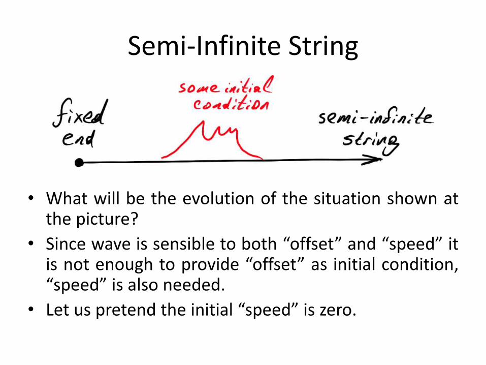
Interference
• Interference pattern isformed when coherentwaves of the samefrequency overlap eachother.
• Waves are coherent whenthey have same frequen-cies and constant phasedifference.
• Non-coherent wave donot form stable interfe-rence patterns.

Interference – Good or Bad?
• Due to interference you can get zero signal strength even in directvisibility of cell tower (destructive interference).
• Typical size of interference patterns is similar to wavelength. Wavelengthfor 2GHz signal is 15 centimeters.
• Transmitters can use multiple antennas to increase bandwidth by meansof constructive interference.

Diffraction
• Diffraction occurs whena wave encounters anobstacle.
• Diffraction can be expla-ined by interference ofthe wave with itself.

Diffraction and InterferenceAlways Appear Together

Diffraction – Good or Bad?
• In radio engineering diffraction is mostly good,since it allows having signal reception evenwithout direct visibility of the transmitter.
• Nevertheless photographers hate diffraction,since it reduces sharpness of their images.
• In microscopy diffraction limits the size ofobjects that can be viewed in opticalmicroscope.

Reciprocity
• Reciprocity of waves is their ability to travelthe same path in both directions.
• If you “reverse in time” the wave propagationprocess, then you still have correct solution tothe wave equation. That is because it hassecond derivative on time.
• Reciprocity is important feature of wavestransferred in linear media.
• Lossy medium is not reciprocal.

Reciprocity Illustration

Reciprocity – Good or Bad?
Reciprocity allows efficient double-sided communi-cation by transmitting the signal in reverse directionto received signal (multiple antennas needed).

Spectrum as a Way to Understand Waves
Although you can transmit signal of arbitrary shape (forexample, rectangular waves instead of sinusoid), the best wayto understand waves is to think of any signal as of sum ofsinusoidal waves:• Different frequencies have different diffraction and
interference patterns. So, harmonics of your transmittedsignal may be received with different attenuation andphase offsets.
• Dispersion: different frequencies may travel with differentspeeds.
• Shapes of transmit and receive antennas andcorresponding electronic circuits are optimized for specificranges of frequencies.
• Usage of radio waves is licensed by frequency ranges.

NON-LINEAR EFFECTS
Non-Linear Effects
• Lossy media.
• Intermodulation.
• Nonlinear signal amplification.

Rusty Bolt Effect
• Oxide layer between dif-ferent metals may act as adiode.
• This leads to frequencies.
• This is an example ofpassive intermodulation.

Nonlinear System – Some Math
Harmonic wave of frequency 𝑓:𝑢 𝑡 = 𝑎 sin 2𝜋 ⋅ 𝑓 ⋅ 𝑡 .
System with quadratic nonlinearity:𝑔 𝑢 = 𝑘 ⋅ 𝑢 + 𝜀 ⋅ 𝑢2.
Output signal:
𝑔 𝑢 𝑡 = 𝑘 ⋅ 𝑎 ⋅ sin 2𝜋 ⋅ 𝑓 ⋅ 𝑡 +
+𝜀𝑎2
21 − cos 2𝜋 ⋅ 2𝑓 ⋅ 𝑡 .
So, double frequency (2𝑓) appeared at the output. The relative power ofintermodulated harmonic is higher when signal amplitude 𝑎 is high. It canalso be shown that combination of two waves will lead to appearance of sumand difference frequency (do it yourself).

Non-Linearity – Good or Bad?
• Nonlinearities in electromagnetic wave transmissionare bad for us, since it is very hard to designcompensation algorithms.
• The same can be told about sound processing: lineardefects can be alleviated by equalizer, but non-lineareffects are source of nasty sound distortions at highsound volume.
• There are 3 main ways of dealing with nonlinearities:– designing quality (highly linear) hardware and keeping it in
good condition (tuning, cleaning, etc);– reducing signal power;– just ignoring non-linear effects.

INFORMATION TRANSMISSION

Channel Capacity
Theoretical limit on the speed of information transmission is given byShannon–Hartley theorem:
𝐶 = 𝐵 log2 1 +𝑆
𝑁.
Here:𝐶— maximal theoretical channel capacity (bits/sec);𝐵— bandwidth (hertz);𝑆— signal power (watts);𝑁— noise power (watts).
In case of wideband signal:
𝐶 =
𝑓𝑚𝑖𝑛
𝑓𝑚𝑎𝑥
log2 1 +𝑆 𝑓
𝑁 𝑓𝑑𝑓 .

Channel Capacity
• Increasing of signal power 𝑆 is not veryproductive way of capacity increasing.
• It is better to increase the bandwidth 𝐵.
• From hardware point of view it is easier toincrease bandwidth for high-frequency signals.
• High-frequency allows hardware miniaturization.

Creative question
• Let us transmit pure sine wave, and turn it on andoff according to Morse code.
• When the wave is on, it has zero bandwidth (𝐵 =0). When the wave is off, it has zero energy (𝑆 =0 ). So in both cases we do not transferinformation according to Shannon–Hartleytheorem.
• Nevertheless we can receive this wave anddecode Morse code. So, information istransferred.
• What is wrong with our reasoning?

Modulation
Harmonic wave with amplitude 𝑎 , frequency 𝑓 , and phase 𝑝 :𝑢 𝑡, 𝑎, 𝑓, 𝑝 = 𝑎 sin 2𝜋 ⋅ 𝑓 ⋅ 𝑡 + 𝑝 .
In order to transfer information we should change some waveproperties:• 𝑎— amplitude modulation (AM);• 𝑓— frequency modulation (FM);• 𝑝— phase modulation (PM).
The modulated wave is called carrier, because it carries ourinformation.

Amplitude modulation
• AM can be digital or analog.
• Our example with Morse code is in fact digitalamplitude modulation.
• In digital modulation we use few fixed levelsof modulated parameter.
• In analog modulation the parameter iscontinuous.

AM Bandwidth
Suppose we want to modify amplitude by somesinusoidal function:
𝑎 𝑡 = 𝑏 sin 2𝜋 ⋅ 𝑔 ⋅ 𝑡 ,then (when phase is fixed it can be considered zero):
𝑢 𝑡, 𝑎 𝑡 , 𝑓 == 𝑏 sin 2𝜋 ⋅ 𝑔 ⋅ 𝑡 sin 2𝜋 ⋅ 𝑓 ⋅ 𝑡 =
=𝑏
2cos 2𝜋 ⋅ 𝑓 − 𝑔 ⋅ 𝑡 − cos 2𝜋 ⋅ 𝑓 + 𝑔 ⋅ 𝑡 .
So, changing amplitude of frequency 𝑓 with frequency 𝑔will require bandwidth 𝑓 − 𝑔, 𝑓 + 𝑔 .

AM as a Sum of Two Waves

Required bandwidth
• We have seen that change of signal amplituderequires wider bandwidth than zero-widthband of pure unmodulated wave.
• It can be shown that change of any signalparameter (amplitude, frequency, phase) willwiden the band according to the frequency ofparameter changing.

Frequency Modulation
• We change carrier frequency (red) according toinformation to be transferred (blue).
• Analog FM radio has higher quality than AM radiosimply because FM has much higher bandwidth.

Digital Frequency Modulation?
• Let us suppose that we switching carrier between2 different frequencies in order to transmit ourbinary data.
• We can think of this process as of two carriersalternately switching their amplitudes betweenzero and non-zero.
• We can transfer more information if will switchthem independently (not alternately).
• So, digital frequency modulation is a special caseof amplitude modulation with multiple carriers.

Phase Modulation
In case of modulation by sinusoidal signal phasemodulation is similar to frequency modulation, exceptfrequency of phase-modulated signal is higher wherederivative of information signal is high, not its value.

Phase Modulation vs Frequency Modulationfor Binary Signal
In order to decode phase-modulated signal receiverand transmitter should be phase-synchronized. So,such transmission is called synchronous.

Combined Phase-AmplitudeDigital Modulation
• We already know that there is no such thingas digital frequency modulation (we canconsider multiple carriers instead).
• For each carrier we have 2 parameters tochange: amplitude and phase.
• But these parameters are not independent:phase shift by 180° is the same as negativeamplitude.
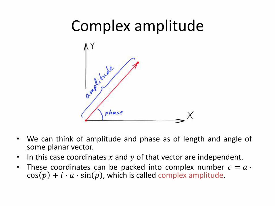
Complex amplitude
• We can think of amplitude and phase as of length and angle ofsome planar vector.
• In this case coordinates 𝑥 and 𝑦 of that vector are independent.• These coordinates can be packed into complex number 𝑐 = 𝑎 ⋅cos 𝑝 + 𝑖 ⋅ 𝑎 ⋅ sin 𝑝 , which is called complex amplitude.

Euler's formula
Remember original harmonic wave:𝑢 𝑡, 𝑎, 𝑓, 𝑝 = 𝑎 sin 2𝜋 ⋅ 𝑓 ⋅ 𝑡 + 𝑝 .
Euler’s formula𝑒𝑖⋅𝑥 = cos 𝑥 + 𝑖 ⋅ sin 𝑥
allows us to easy deal with complex amplitude:
𝑢 𝑡, 𝑐, 𝑓 = Im 𝑐 ⋅ 𝑒2𝜋𝑖⋅𝑓⋅𝑡 ,
where 𝑐 = 𝑎 ⋅ cos 𝑝 + 𝑖 ⋅ 𝑎 ⋅ sin 𝑝 = 𝑎 ⋅ 𝑒𝑖⋅𝑝.

QAM Modulation
• Peek some fixed set of complex amplitude points and encode yourinformation by switching carrier between these points.
• Such set is called QAM constellation.• Each point encodes several bits and called QAM symbol.• The more points are packed in QAM symbol the faster the information
will be transferred, but symbols with many points are sensible to noise.So, balance is needed.

QPSK Constellation
• QPSK is the most com-mon example of QAMmodulation.
• All points have the samedistance from zero, soQPSK can be consideredas pure phase modulationwith 4 fixed phases.
• Alternatively you canthink of QPSK as having 2phases and 2 amplitudes.
• Each QPSK symbol carry 2bits of information.

Linear Distortion of Symbols
• The unique feature of QAM symbols is that they are distorted thesame way the carrier is distorted (we talk about linear distortionshere).
• If wave is delayed by some time amount then each transmittedsymbol is delayed too. This delay can be interpreted as phase shiftboth in carrier and QAM symbols (rotation of symbol constellationsaround zero).
• The amplitude of each symbol is changed the same way the carrieramplitude is changed. So, symbol constellations are scaled.
• The carrier frequency can not be changed in linear transmissionmedia. This corresponds to the absence of frequency information inQAM symbols.
• So we can forget about carrying waves and imagine that symbolsare directly transmitted and received as complex numbers.

Linear Channel
• We come to the simple and fundamental conceptof linear transmission media and QAM modu-lation: linear channel.
• The main idea:– Transmitter antenna transmits stream of complex
values (symbols).
– These numbers flying in the air, bounce of walls etc,and finally come into the receiver antenna.
– Most of distortions can be combined into singlecomplex value which slowly changes in time.

Linear Channel
The final formula:𝑦𝑖 = 𝐻𝑖 ⋅ 𝑥𝑖 + 𝑛𝑖 .
Here:𝑥𝑖 ∈ ℂ— 𝑖-th transmitted symbol;𝑦𝑖 ∈ ℂ— 𝑖-th received symbol;𝐻𝑖 ∈ ℂ— channel state when the 𝑖-th symbol was transmitted;𝑛𝑖 ∈ ℂ— noise of 𝑖-th received symbol.
Channel 𝐻𝑖 and noise 𝑛𝑖 are usually normalized so that noise has unit power:
𝐸 𝑛𝑖2 = 1.
The channel𝑀 slowly changes in time:𝐻𝑖+1 ≈ 𝐻𝑖 .
It should be noted that a large time can pass from the transmission of symbol toreceiving of this symbol. But that time is not important for most of the tasks.

Reciprocity Model
Symbol transmitted from 𝐴 to 𝐵:
𝑦𝑖𝐴 = 𝐻𝑖
𝐴𝐵 ⋅ 𝑥𝑖𝐴 + 𝑛𝐴.
Symbol transmitted from 𝐵 to 𝐴 at the same time:
𝑦𝑖𝐵 = 𝐻𝑖
𝐵𝐴 ⋅ 𝑥𝑖𝐵 + 𝑛𝐵 .
Reciprocity equality:
𝐻𝑖𝐴𝐵 = 𝐻𝑖
𝐵𝐴.

Pilot Symbols
• You may wonder how can transmitted information bedecoded if each symbol is randomly rotated andscaled?
• These distortions changing slowly in time, so we cantransmit thousands of symbols with mostly the samedistortions.
• Transmitter sends symbols in packets and adds intoeach packet few special symbols with predefinedvalues. These special symbols are called pilot symbols.
• Receiver knows that each packet has pilot symbols incertain positions, and can use them to correctly decodephase and amplitude of other received symbols.

Symbol Rate
• Each QAM symbol is transmitted by severalperiods of carrier wave (typically from 10 to100 periods).
• The frequency of symbol transmission is calledsymbol rate.
• So, in noiseless case transmission rate is thesymbol rate multiplied by number of bits persymbol.
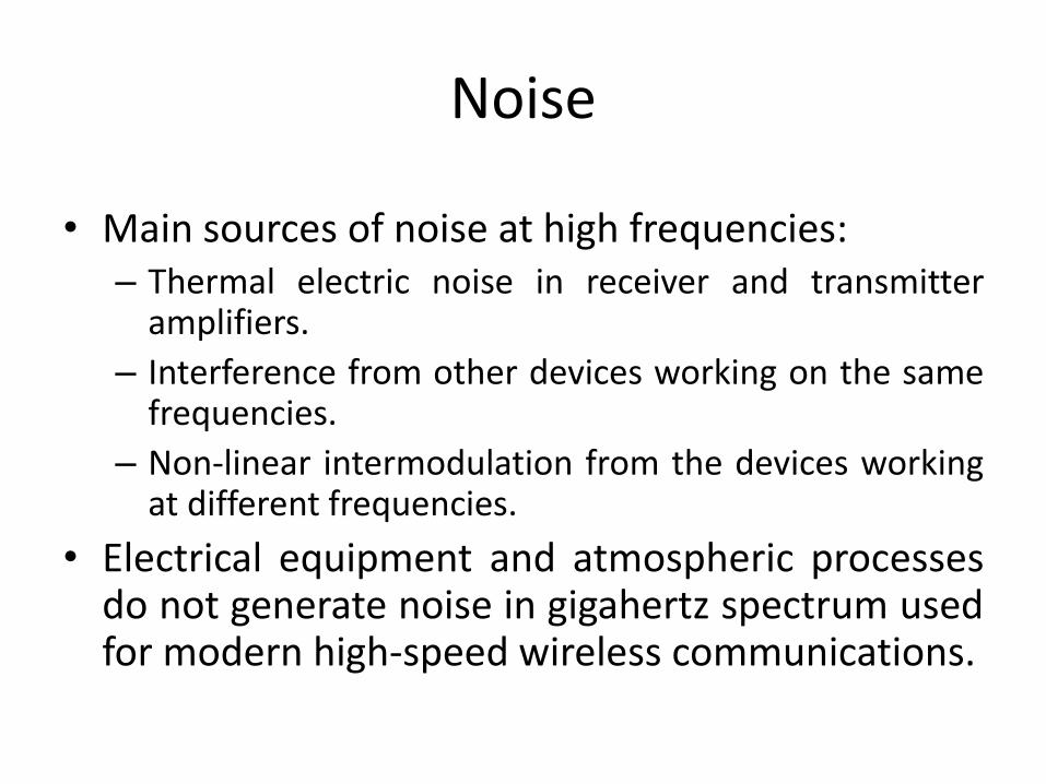
Noise
• Main sources of noise at high frequencies:– Thermal electric noise in receiver and transmitter
amplifiers.
– Interference from other devices working on the samefrequencies.
– Non-linear intermodulation from the devices workingat different frequencies.
• Electrical equipment and atmospheric processesdo not generate noise in gigahertz spectrum usedfor modern high-speed wireless communications.

Methods of Dealing with Noise
• Use more transmission power.• Use smart antenna arrays capable of sending signal at
the direction of receiver.• Transmit less bits per symbol, so different constellation
points are separated by larger energy gaps.• Reduce symbol rate, so each symbol will be longer and
have more energy.• Use forward error correction, so small amount of
errors can be fixed without retransmission.• Use automated repeat requests for retransmitting
damaged parts of data.
MULTI-ANTENNA COMMUNICATIONS

Why Multiple Antennas?
• Transmitter can use multiple antennas to send signal exactly wherethe receiver is (remember reciprocity illustration). Thus, more signalpower will go to the receiver (larger signal-to-noise ratio).
• Receiver can use multiple antennas to listen to the direction thesignal comes from. Thus more signal will be received.
• But the most important thing is that multiple antennas in bothreceiver and transmitter allow creation of several parallel virtualwireless channels at the same frequency. That is called MIMO —multiple input and multiple output transmission medium.
• The systems with single transmit and single receive antennasmentioned before are called SISO (single input and single output).

2×2 MIMO System
If transmitter and receiver have 2antennas each then we have total 4channels, which can be described by 2×2matrix𝑯:
𝑦 = 𝑯 ⋅ 𝑥 + 𝑛.Here 𝑥 is vector of transmitted symbols(one per antenna), and 𝑦 is vector ofreceived symbols, 𝑛 is vector of noisevalues.
It is convenient to normalize channel 𝑯relative to noise, so that each componentof noise vector has unit variance.
Transmit power:𝑆 = 𝑥𝑇 𝑥 = tr 𝑥 ⋅ 𝑥𝑇 .

MIMO Capacity?
• We cannot calculate capacity of MIMOchannel as sum of capacities of all antenna-to-antenna subchannels (4 subchannels in caseof 2×2 MIMO system), because suchsubchannels are correlated (cannot transferinformation independently).
• We will learn how to calculate MIMO capacitylater.

Channel State Information
• Channel state information is the knowledgeabout the channel the transmitter and thereceiver have.
• Channel matrix 𝑯 can be part of thisknowledge.
• Other part of knowledge is error rate, which isrelated to signal-to-noise ratio.
• Precise channel state information is crucial toattain highest channel throughput.
Time-Division Duplexing
• A duplex communication system is a system wheredevices communicate in both directions.
• Time-division duplexing (TDD) is when devices transmitdata by turns at the same frequency.
• TDD is the simple way to obtain precise channel stateinformation:– Receiver uses pilot symbols to decode data packet and to
calculate channel𝑯𝐴𝐵.– Then channel reciprocity is used to calculate channel in
opposite direction:𝑯𝐵𝐴 = 𝑯𝐴𝐵𝑇 .
– Calculated channel 𝑯𝐵𝐴 can be used to optimally transmitdata when the receiver becomes transmitter.

Simple MIMO System
• Let us consider MIMO system, where transmittersimply transmits different symbols from differentantennas.
• Transmitted symbols become linearly mixed inthe air, and such mixes arrive to the receiver(different mixes to different antennas).
• Can the receiver decode the symbols were sent?
• May be, if matrix 𝑯 is invertible: 𝑥′ = 𝑯−1 ⋅ 𝑦.

Noise Gain
Let us consider the noise: 𝑥′ = 𝑯−1 ⋅ 𝑦 = 𝑯−1 𝑯 ⋅ 𝑥 + 𝑛 = 𝑥 + 𝑯−1 ⋅ 𝑛.
• Symbol vector is almost recovered, except that noise vectoris multiplied by the inverted channel matrix.
• Should we worry about that?• Yes! Channel matrix usually has small norm due to high
subchanels correlation, so the inverted matrix has largenorm, the noise is amplified, and data cannot be recoveredat the receiver.
• We conclude that transmitter cannot just use its antennasas independent transmit subchannels.

Linear Precoding
In order to reduce noise gain in MIMO system the transmitter and thereceiver should cooperate. One way to implement such cooperation is calledlinear precoding:
𝑥𝑡 = 𝑷 ⋅ 𝑥,where 𝑥𝑡 is signal sent to antennas (which are “physical” subchannels), 𝑷 iscalled precoding matrix (which is mapping between physical and some“virtual” subchannels), 𝑥 is vector of symbols sent to “virtual” subchannels.
Precoding matrix should not change transmitted power:tr 𝑷𝑷𝐻 = 1.
The receiver should invert both the channel and precoder to decode data: 𝑥′ = 𝑷−1𝑯−1 ⋅ 𝑦 = 𝑷−1𝑯−1 𝑯𝑷 ⋅ 𝑥 + 𝑛 =
= 𝑥 + 𝑷−1𝑯−1 ⋅ 𝑛.
How Linear Precoding Can Help?
The intuition behind linear precoding is thatvirtual MIMO channel 𝑯 ⋅ 𝑷 can have highercapacity than physical MIMO channel𝑯.

Optimal Solutionto Linear Precoding Problem
Surprisingly, the optimal solution is given by SVDdecomposition of channel matrix:
𝑼,𝜮, 𝑽 = SVD 𝑯 ,where𝑽 is used to calculate optimal precoder,𝜮 contains inverse noise values of virtual subchannels,𝑼𝐻 is optimal decoder.
Virtual subchannels created by SVD precoding areindependent (orthogonal) and thus their total capacity isequal to sum of their capacities.

Power Allocation Problem
• Suppose that we have several independentsubchannels having noise powers 𝑁𝑖 , 𝑖 = 1…𝑚.
• We have transmitter with power 𝑆.
• We want to distribute 𝑆 power among 𝑚subchannels such that we have maximal totalcapacity:
𝑖=1
𝑚
log2 1 +𝑆𝑖𝑁𝑖⟶max,
𝑖=1
𝑚
𝑆𝑖 = 𝑆.

Water-Filling Power Allocation
The solution to the power allocation problem is given bya so-called water-filling algorithm:
𝑆𝑖 = max 𝜇 − 𝑁𝑖 , 0 ,
Where 𝜇 is selected to satisfy power constraint:
𝑖=1
𝑚
𝑆𝑖 = 𝑆.
You can obtain this result by yourself using method ofLagrange multipliers.

Why “Water Filling”?
• Imagine that you have volume 𝑆 of water which is used to fill a vessel withvariable bottom height. The water will find its level 𝜇.
• Each part of the vessel has bottom height equal to noise power of correspondingsubchannel.
• Then the height of water in each part of vessel will equal to power to be allocatedto corresponding subchannel.
• Some parts of vessel will not be covered by water. These parts correspond tosubchannels with so strong noise, that it is better to not use them at all.

Water-Filling for SVD Precoding
In case of SVD precoding virtual channels areindependent, with noise powers 𝑁𝑖 = 1 𝜮 𝑖
2.
Plugging that into water-filling algorithm we getoptimal power allocation matrix:
𝑺 = diag 𝑆1, … , 𝑆𝑚 .
This matrix can be used in addition to precoder toget maximal capacity:
𝑥𝑡 = 𝑷 ⋅ 𝑺 ⋅ 𝑥

Comments on MIMO Precoding
• Water-filling algorithm may select less number ofchannels than the rank of matrix 𝑯 if somesubchannels are “bad” (have high noise).
• Such bad subchannels correspond to smallsingular values of matrix𝑯.
• In the worst case MIMO system will degrade tosingle-channel system, but nevertheless willperform better than SISO system.
• We have omitted here some peculiarities such asadaptive selection of symbol rate and QAMconstellation for each virtual subchannel.

MIMO Channel Capacity
Shannon–Hartley formula can be generalized to MIMO channels. The formulagives maximal theoretical capacity of MIMO channel with perfect channelstate information (compare this to SISO capacity):
𝐶 = 𝐵 log2 det 𝑰 + 𝑫2𝑺2 = 𝐵
𝑖=1
𝑚
log2 1 +𝑆𝑖𝑁𝑖.
Here:𝐶— maximal theoretical channel capacity (bits/sec);𝐵— bandwidth (hertz);𝑰— identity matrix;
𝑫 = diag 1 𝑁1 , … , 1 𝑁𝑚 — matrix containing singular values of MIMOchannel𝑯 (normalized, see note at “2×2 MIMO System” slide);
𝑺 = diag 𝑆1, … , 𝑆𝑚 — optimal power allocation matrix given by water-fillingalgorithm.
As you can see SVD precoding achieves maximal MIMO capacity.