Computational Fluid Dynamics Analysis of Two-Phase Flow in a Packed Bed Reactor
Fuel 100 (2012) 48–56
Contents lists available at SciVerse ScienceDirect
Fuel
journal homepage: www.elsevier .com/locate / fuel
Computational Fluid Dynamics in chemical reactor analysis and design:Application to the ZoneFlow™ reactor for methane steam reforming
Juray De Wilde a,⇑, Gilbert F. Froment b
a Université catholique de Louvain, Materials & Process Engineering (iMMC-IMAP), Place Sainte Barbe 2, 1348 Louvain-la-Neuve, Belgiumb Chemical Engineering Department, Texas A&M University, 3122 TAMU, College Station, TX 77843, USA
a r t i c l e i n f o a b s t r a c t
Article history:Received 14 June 2011Received in revised form 17 August 2011Accepted 23 August 2011Available online 29 December 2011
Keywords:Methane steam reformingHydrogenSynthesis gasProcess intensificationReactor design
0016-2361/$ - see front matter � 2011 Elsevier Ltd. Adoi:10.1016/j.fuel.2011.08.068
⇑ Corresponding author. Tel.: +32 10478193; fax: +E-mail addresses: [email protected] (
tamu.edu (G.F. Froment).
The ZoneFlow reactor (Tribute Creations, LLC) is a tubular reactor with two types of internals: a core typeand adjacent to the wall, a casing type, both covered with a thin layer of catalyst. It aims for higher energyefficiency and lower steam-to-carbon ratios in methane steam reforming by a judicious design of the rel-ative position of the internals and their geometrical characteristics and a higher catalyst effectiveness.
The performance of this novel structured catalytic reactor for synthesis gas production by methanesteam reforming was simulated using a reactor model accounting in detail for the flow pattern by meansof Computational Fluid Dynamics (CFD). A Reynolds Averaged Navier Stokes (RANS) approach was taken.Turbulence, heat transfer by convection and radiation, detailed reaction kinetics including coking, intra-particle diffusion limitations, and the compressibility of the gas phase were accounted for. Simulationswere carried out to investigate the ZoneFlow reactor performance under typical commercial operatingconditions and compare it with a conventional packed bed reactor using the same Ni catalyst.
� 2011 Elsevier Ltd. All rights reserved.
1. Introduction
Steam reforming of natural gas is the most important processfor the production of hydrogen and synthesis gas. Commerciallyit is carried out in a fixed bed reactor. The catalyst essentially con-sists of Ni on alumina. The methane reactions are highly endother-mic and the reactor tubes are inserted in a gas-fired furnace. Toavoid too pronounced radial temperature gradients, the reactortube diameter is typically limited to 10 cm. The process gas tem-perature evolves from 675 to 1000 K and the operating pressureis around 30 bar. Very high heat fluxes are required, imposing se-vere demands on the tube material. In conventional fixed bed reac-tors the throughput and methane conversion per tube are limitedby the heat transfer from the furnace to the process gas. The heattransfer coefficient between the process gas and the reactor walland the maximum allowable tube wall temperatures are evidentlyimportant elements of the reactor design and performance.
In methane steam reforming coke formation is quite common. Itis detrimental for the catalyst activity and for heat transfer. Cokecan even cause plugging of the reactor tubes and fouling in down-stream equipment by entrainment of carbon whiskers [1–3]. Cokegasification by hydrogen or by steam is one of the factors deter-mining the steam to carbon ratio of the reformer feed [4]. The
ll rights reserved.
32 10474028.J. De Wilde), g.froment@che.
potential for coke formation is highest at high temperatures.Therefore, the radial heat transfer in the reactor is an importantoperating factor.
Intra-particle diffusion limitations were shown to be veryimportant in methane steam reforming in fixed bed reactors. Effec-tiveness factors as low as 0.05 have been reported [5]. An increasedcatalyst effectiveness can be achieved by using smaller catalystpellets, but at the expense of a higher pressure drop. The commer-cially used catalyst pellet size follows from an optimizationaccounting for the catalyst effectiveness and the pressure drop,as well as the mechanical strength of the pellets.
The present paper evaluates the potential of a catalytic reactorwith a novel structure, ZoneFlow [6,7], for improving the heattransfer between the reactor tube inner wall and the process gas,reducing the pressure drop, increasing the catalyst effectiveness,and allowing operation at lower steam-to-carbon ratios. The simu-lation model involves Computational Fluid Dynamics (CFD) incombination with detailed reaction kinetics, including those forcoke formation and gasification. The results are compared withthose obtained in a conventional fixed bed reactor.
2. The ZoneFlow reactor
The ZoneFlow reactor comprises two interconnected zones, theso-called casing (or wall zone) and the core [6,7]. The casing con-sists of rows of centripetal and centrifugal blades, staggered witha given axial spacing. The core consists of staggered perforated

Nomenclature
av external particle surface area per unit reactor volumeðm2
p=m3r Þ
cp specific heat of fluid at constant pressure (J/kg K)CA molar concentration of species A ðkmol=m3
f ÞCs
AS molar concentration of fluid reactant at surface of solidðkmol=m3
f Þd catalyst coating layer thickness (m)DA,m molecular diffusivity of A in a multicomponent mixture
ðm3f =mf sÞ
Deff effective diffusivity in a fluid ðm3f =mf sÞ
Dt turbulent diffusivity in a fluid ðm3f =mf sÞ
E total energy, consisting of internal and kinetic energy (J/kg)
g gravity (m/s2)hf coefficient of heat transfer over the film between a wall/
catalyst surface and the process gas (J/(m2 s K))k turbulent kinetic energy (J/kg)kg mass transfer coefficient from gas to solid interface
ðm3f =m2
i sÞpA partial pressure component A (Pa or bar)P total pressure (Pa)r1 rate of reaction 1 per unit catalyst mass (kmol/(kg cat s)
or kmol/(kg cat h) or kmol/(m2 s))
rA rate of reaction of component A per unit catalyst mass(kmol/(kg cat s) or kmol/(kg cat h) or kmol/(m2 s))
rC rate of coke deposition (kg coke/(kg cat s) or kmol/(kg cat h) or kmol/(m2 s))
Tg gas phase temperature (K)Ts solid phase temperature (K)uj j component of the velocity (mr/s)zj distance coordinate in j direction (m)aij stoichiometric coefficient of component j in the ith reac-
tione turbulence dissipation rate ðm2
r =s3Þes solid phase volume fraction ðm3
s =m3r Þ
g effectiveness factor for solid particlekeff effective thermal conductivity (J/m s K)km molecular thermal conductivity (J/m s K)kr radiative conductivity (J/m s K)kt turbulent conductivity (J/m s K)lg dynamic viscosity (Pa s)leff effective viscosity (Pa s)lt turbulent viscosity (Pa s)qg gas density ðkg=m3
gÞqs density of catalyst ðkg cat=m3
pÞsji shear stress tensor, jith component (kg/(m s2))
J. De Wilde, G.F. Froment / Fuel 100 (2012) 48–56 49
smooth and corrugated cones. A small gap near the wall of thereactor allows communication between the centrifugal and cen-tripetal blade zones. A picture of a typical ZoneFlow structure isshown in Fig. 1a.
The ZoneFlow reactor with its two zones aims for improvedheat transfer from the inner wall of the tube to the process gas,for higher catalyst effectiveness and reduced pressure drop withrespect to conventional packed bed reactors. These features makeZoneFlow reactors attractive for natural gas steam reforming,
reac
tora
xis
reac
torw
all
cones
blad
es
radi
al fi
ns
corr
ugat
ions
(a) (b)Fig. 1. (a) Typical ZoneFlow structure. (b) Schematic overview of the simulatedZoneFlow reactor – focus on the top section of the reactor.
allowing for increased throughputs/conversions and reducedsteam-to-carbon ratios.
3. Simulation model
The ZoneFlow reactor behavior is simulated in 3D using Compu-tational Fluid Dynamics (CFD). A Reynolds Averaged Navier Stokes(RANS) approach is taken to calculate the statistically steady statesolution. The effects of turbulence are modeled by means of theturbulent kinetic energy k and the turbulence dissipation rate e,for which extra transport equations have to be solved. The com-plete set of transport equations and the boundary conditions atthe internals coated with catalyst and at the heated walls are sum-marized below. Details on CFD, the RANS approach and the model-ing of turbulence can be found in Froment et al. [8].
3.1. Continuity and constitutive equations
The continuity equations for a species A in the gas phase can bewritten as:
@
@zjðCAujÞ �
@
@zjDA;eff
@CA
@zj
� �¼ 0 ð1Þ
Notice that the Einstein notation is used throughout the paperand that no reactions occur in the gas phase. On solid internalscoated with catalyst:
kgAðCs
As � CAÞ ¼ qsdX
k
aAkgkrkðCss; TsÞ ¼ esqs
Xk
aAkgkrkðCss; TsÞ=av
ð2Þ
with d the catalyst coating thickness. The effective diffusion coeffi-cient consists of a molecular and a turbulent contribution:
DA;eff ¼ DA;m þ Dt ð3Þ
The turbulent diffusivity is assumed to be proportional to theturbulent viscosity:

Table 2Rate equations for the steam reforming of methane [5] and for coke formation andgasification [17]. Thermodynamic and rate constants: see Table 3. Reaction ratesaccording to the reaction mechanism shown in Table 1 are expressed in [kmol/(kgcat h)], the partial pressures in bar.
Methane steam reforming:Reaction-1 k p3
H pCO
� �2
50 J. De Wilde, G.F. Froment / Fuel 100 (2012) 48–56
Dt ¼lt
qgSctð4Þ
Sct is the turbulent Schmidt number. Following Spalding [9], Sct
was given a value 0.7. Details on the reaction mechanism and kinet-ics are given in the next section. Intra-particle diffusion limitationswere accounted for via the catalyst effectiveness factors. To reduceintra-particle diffusion limitations, the catalyst layer thickness waslimited to 80 lm. Calculating the effectiveness factors for the threereactions in each point of the reactor through the integration of aset of second order differential equations was prohibitive in thisCFD simulation. Therefore, based upon the relation between theeffectiveness factors and the intra-particle concentration gradientsas simulated by Xu and Froment [5], a value of 0.5 was chosen forthe effectiveness factors of reactions 1 and 3 (Table 1) in the 80 lmcatalyst layer. That of reaction 2 was chosen to be unity. The effec-tiveness factors of the coking reactions, which are much slower thanthe main methane steam reforming reactions, are assumed to be one.
The gas phase total continuity equation is:
@
@zjðqgujÞ ¼ 0 ð5Þ
The gas phase momentum equations can be written:
@
@zjðqguiujÞ ¼ �
@Peff
@ziþ@sji
@zjþ qggi ð6Þ
with i = x, y, z and the gas phase shear stress tensor defined as:
sji ¼ leff@ui
@zjþ @uj
@zi� 2
3dij@uk
@zk
� �ð7Þ
The effective mean pressure and the effective viscosity in (6)consist of a molecular and turbulent contribution:
Peff ¼ P þ 23qgk ð8Þ
leff ¼ lg þ lt ð9Þ
The turbulent viscosity is expressed in terms of k and e accord-ing to:
lt ¼ Clqgk2
eð10Þ
with Cl the model constant. At solid walls, the no-slip condition isapplied. The wall shear stress is calculated from the well knownlogarithmic law [10,11]:huius¼ 1
jln
y1us
mCE
h iwith sw ¼ u2
sqg ð11Þ
y1 is the distance to the wall, CE an empirical constant and j the vonKarman constant. The logarithmic law is valid for values ofyþ ¼ y1us=m around 50.
The gas phase energy equation can be written:
@
@zjðqgEgujÞ �
@
@zjkeff
@Tg
@zj
� �¼ � @
@zjðPeff ujÞ þ
@
@zjðuisjiÞ
þ qggjuj ð12Þ
Table 1Reaction mechanism for the steam reforming of methane [5] and for coke formationand gasification [17].
Methane steam reforming:Reaction-1: CH4 þ H2O() COþ 3H2
Reaction-2: (water gas shift) COþ H2O() CO2 þ H2
Reaction-3: CH4 þ 2H2O() CO2 þ 4H2
Coke formation and gasification:Reaction-C1: (cracking) CH4 () Cþ 2H2
Reaction-C2: (Boudouard) COþ H2 () Cþ H2O
At heated solid walls, the convective heat flux is:
Qw ¼ hf ðTiw � TgÞ ð13Þ
in which hf is the coefficient of heat transfer over the film betweenthe wall and the process gas and Ti
w is the reactor tube inner walltemperature. Temperature wall functions were used that includea contribution from viscous heating [12,13]. At solid internalscoated with catalyst:
hf ðTs � TgÞ ¼ qsdX
k
gkrkðCss; TsÞð�DHkÞ ð14Þ
The effective conductivity in (12) is the sum of the molecular,radiative and turbulent conductivities:
keff ¼ kg þ kr þ kt ð15Þ
A gray radiation model and the Rosseland or diffusion approxi-mation for radiation were adopted (Siegel and Howell, 1981). Thelatter assumes that the radiation intensity is the black-body inten-sity at the gas temperature. This is valid when the medium is opti-cally thick. Linearization of the radiative heat flux in a graymedium results in:
kr ¼ 16rCn2T3g ð16Þ
where n is the refractive index. The radiative conductivity kr can beexpressed as a function of an absorption coefficient and a scatteringcoefficient. They describe the change in radiation intensity per unitlength along the path through the fluid medium. A gray radiationmodel is used that assumes that the absorption coefficient is inde-pendent of the band. At solid walls, a temperature slip boundarycondition is used to calculate the radiative heat flux [14]. The turbu-lent conductivity is assumed to be proportional to the turbulentviscosity:
kt ¼cPlt
Prtð17Þ
Prt, the turbulent Prandtl number, has a typical value of 0.85.The turbulent kinetic energy and its dissipation rate are re-
quired to calculate the turbulent viscosity (10). The standard k–emodel was used. The transport equation for k is:
@qgkhuii@zi
¼ @
@zilg þ
lt
rk
� �@k@zi
� �þ Pk þ Bk � qge ð18Þ
Pk is the turbulent kinetic energy production, Bk the turbulencedue to gravity and rk the model parameter [15–17]. Turbulencedue to gravity can be modeled as:
r1 ¼ 1p2:5
H2
pCH4pH2 O � 2
K1=ðDENÞ
Reaction-2 r2 ¼ k2pH2
pCOpH2O �pH2
pCO2K2
� �=ðDENÞ2
Reaction-3r3 ¼ k3
p3:5H2
pCH4p2
H2 O �p4
H2pCO2
K3
� �=ðDENÞ2
with DEN ¼ 1þ KCOpCO þ KH2 pH2þ KCH4 pCH4
þ KH2OpH2 O=pH2
Coke formation and gasification:Reaction-C1 rC1 ¼ kþM ~KCH4 pCH4
�pH2K�M
� �=ðDEN2Þ2
Reaction-C2rC2 ¼ k�O KCOpCO �
kþ0
OKO;H2 O
pH2 O
pH2
� �=ðDENÞ2
with DEN2 ¼ 1þ KCOpCO þ ~KCH4 pCH4þ 1
K 00rp1:5
H2þ 1
KO;H2 O
pH2 O
pH2

Table 3Thermodynamic and rate constants for the rate equations for the steam reforming ofmethane and for coke formation and gasification on the ICI 46-9 S catalyst (NiO:16 wt.%; K2O: 2 wt.% in bulk, 1.2 wt.% at the surface), as shown in Table 2 [5,17].
Parameter Value Parameter Value
k1 4:225� 1015 � e �240100RTð Þ k�O 1:33� 10�6 � e 75955
RTð Þk2 1:955� 106 � e �67130
RTð Þ kþ0
O 1:67� 109 � e �148916RTð Þ
k3 1:020� 1015 � e �243900RTð Þ ~KCH4
0.1099
K1 10�11650
T þ13:076ð Þ K�M e142:5
Rð Þ � e�123226
RTð ÞK2 10
1910T �1:764ð Þ KO;H2 O 1:7372� 104 � e �60615
RTð ÞK3 10
�9740T þ11:312ð Þ K 0r 2:51893� 105 � e �95489
RTð ÞKCO 8:23� 10�5 � e 70650
RTð Þ DH1 224000.0 (at 948 K)
KH2 6:12� 10�9 � e 82900RTð Þ DH2 �37300.0 (at 948 K)
KCH4 6:65� 10�4 � e 38280RTð Þ DH3 187500.0 (at 948 K)
KH2O 1:77� 105 � e �88680RTð Þ DHC1 74870.0 (at 298 K)
kþM 5:5619� 104 � e �65053RTð Þ DHC2 �131325.0 (at 298 K)
With: R = 8.314472 J/(mol K) and DH1, DH2, DH3, DHC1, DHC2, the enthalpy changeof Reactions-1, -2, -3, -C1, and -C2 (see Table 1), that is the opposite of the heat ofreaction, in (J/mol).
Table 4ZoneFlow reactor geometry and operating conditions in methane steam reforming –typical commercial and lower steam-to-carbon ratio.
ZoneFlow reactor design
Length 1 mDiameter 0.1 mSimulated sector 10�
Cones:Smooth 60Corrugated 60Holes 144Hole diameter 1.5 mm
Blades:Centripetal 60Centrifugal 60
Catalyst layer 80 lm (Ni)=40.236 kg cat. eff/m3 reactor
Near-wall gap 2.3 mm
Operating conditionsTotal feed rate 534.17 Nm3/hInlet temperature 793.15 KFeed composition (mole fraction)N2 0.0348 0.03490CH4 0.2128 0.3434CO 0.0 0CO2 0.0119 0.0192H2O 0.7145 0.5765H2 0.0260 0.0260S/C-ratio 3.36 1.68Outlet pressure 29 barWall temperature 1170 K
J. De Wilde, G.F. Froment / Fuel 100 (2012) 48–56 51
Bk ¼ bgilt
Prt
@Tg
@zið19Þ
in which b is the thermal expansion coefficient:
b ¼ � 1qg
@qg
@Tg
� �P
ð20Þ
A semi-empirical transport equation for e is commonly used:
@qgehuii@zi
¼ @
@zilþ lt
re
� �@e@zi
� �þ Ce1
ekðPk þ Ce3BkÞ � Ce2qg
e2
kð21Þ
re, Ce1, and Ce2 are the model parameters determined from experi-mental data [15–17]. The standard k–e model is robust and offers areasonable accuracy for a wide range of turbulent flows. It cannotbe applied in the viscous sub-layer near solid walls, however. Wallfunctions are used for the logarithmic layer [16]:
reac
tora
xis
flowdirection
smooth and corrugated perforated cones
(a)Fig. 2. (a) Velocity vector profile in a cross section with centrifugal blades in the casin(relative to the outlet pressure). Reactor characteristics and operating conditions: see Ta
kwall ¼u2
sffiffiffiffiffiffiCl
p ð22Þ
ewall ¼u4
s50jm
¼ u3s
jy1ð23Þ
us is obtained from (11).
reac
torw
all
wall zonewith blades
(b)g. (b) Pressure (Pa) profile in a cross section with centripetal blades in the casingble 4, S/C = 3.36.
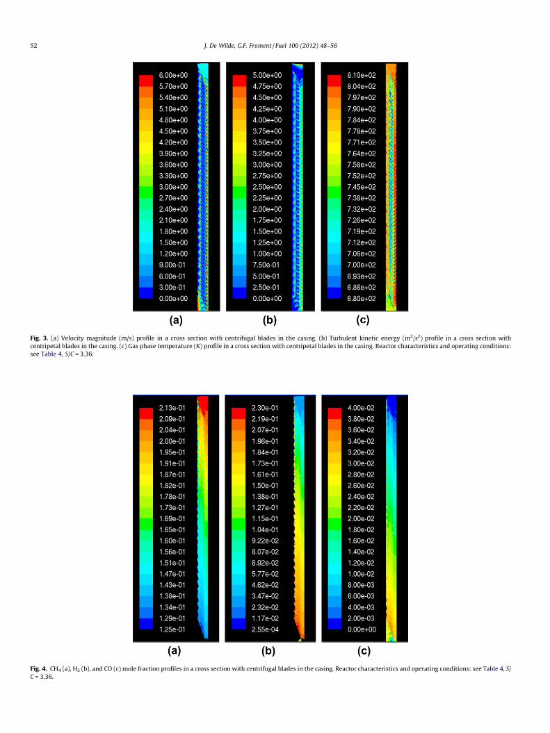
Fig. 3. (a) Velocity magnitude (m/s) profile in a cross section with centrifugal blades in the casing. (b) Turbulent kinetic energy (m2/s2) profile in a cross section withcentripetal blades in the casing. (c) Gas phase temperature (K) profile in a cross section with centripetal blades in the casing. Reactor characteristics and operating conditions:see Table 4, S/C = 3.36.
Fig. 4. CH4 (a), H2 (b), and CO (c) mole fraction profiles in a cross section with centrifugal blades in the casing. Reactor characteristics and operating conditions: see Table 4, S/C = 3.36.
52 J. De Wilde, G.F. Froment / Fuel 100 (2012) 48–56

0
0.05
0.1
0.15
0.2
0.25
0.3
0.35
0.4
0 0.2 0.4 0.6 0.8 1z (m)
Ave
rage
d m
etha
ne c
onve
rsio
n
Zoneflow™ reactor (40.236 kg cat eff / m3 reac)
Zoneflow™ reactor (17.302 kg cat eff / m3 reac)
Conventional reactor (Xu and Froment, 1989)(17.302 kg cat eff / m3 reac)
Fig. 5. Comparison of the cross section averaged methane conversion in aconventional fixed bed reactor and in ZoneFlow reactors with two differenteffective catalyst ‘‘bed densities’’. For the other ZoneFlow reactor characteristics andoperating conditions: see Table 4, S/C = 3.36.
J. De Wilde, G.F. Froment / Fuel 100 (2012) 48–56 53
3.2. The mechanism and kinetics of methane steam reforming
The fundamental kinetic model for steam reforming of methaneon a Ni catalyst of Xu and Froment [5] was used in (2). The cokingreactions were accounted for using the kinetic model of Snoecket al. [18,19]. The reaction mechanism is summarized in Table 1.The rate equations for the reactions of the steam reforming ofmethane and the coke formation and gasification, as summarizedin Table 1, are shown in Table 2. The thermodynamic and rate con-stants for the ICI 46-9 S catalyst (NiO: 16 wt.%; K2O: 2 wt.% in bulk,1.2 wt.% at the surface) are given in Table 3.
The coking model presented here permits predicting the initialcoke formation rates and, therefore, the locations in the reactorcritical for coking.
Fig. 6. Profiles in a cross section with centripetal blades in the casing: (a) net rate CH4 ()rate of coke formation accounting for CH4 () Cþ 2H2 and COþ H2 () CþH2O (adaptUpper side of the cones shown. Reaction rates in [kmol/(m2 s)]. Negative value indicate
4. Simulation set-up: reactor geometry, operating conditionsand solution algorithm
The structure of the simulated ZoneFlow reactor was chosen tofit within the 100 mm diameter tubes typical for present day com-mercial packed bed steam reformers. The axial spacing of 16 mmbetween the centripetal and centrifugal blades in the casing waschosen to equal that of the axial spacing between the cones inthe core. In order to prevent channeling and improve mixing aswell as the contact between the gas and the catalyst surfaces, theholes in the smooth and the corrugated cones and those in the evenand uneven smooth cones were differently positioned. Each cone,smooth or corrugated, contained 144 holes with a diameter of1.5 mm. A 2.3 mm gap near the wall of the reactor was accountedfor. To increase the catalyst effectiveness factors and to limit thepressure drop over the reactor, the catalyst layer thickness waslimited to 80 lm. A 10� sector of a ZoneFlow reactor with a lengthof 1 m was simulated, capturing all essential elements of the com-plex geometry. The flow pattern was already fully developed after30 cm. A schematic overview of the top section of the simulatedZoneFlow reactor geometry is given in Fig. 1b.
The commercial operating conditions described by Xu andFroment [5] were applied with a typical steam-to-carbon ratio of3.36. Next, simulations at the lower steam-to-carbon ratio of1.68 were carried out. The characteristics of the simulation geom-etry and the operating conditions are summarized in Table 4.
The set of continuity and constitutive Eqs. (1)–(23) is solvednumerically by means of the SIMPLE algorithm [20]. To facilitateconvergence, a semi-implicit time-stepping technique was used. Asecond order upwind discretization scheme of the convective termsis applied. The viscous terms are discretized using a central scheme.A grid independency study was carried out. The simulations used agrid composed of about 800,000 cells. The typical calculation timeon 8 AMD Opteron 850/2.4 GHz processors was 6 weeks.
Cþ 2H2 (adapted scale); (b) net rate COþ H2 () CþH2O (adapted scale); (c) neted scale). Reactor characteristics and operating conditions: see Table 4, S/C = 3.36.
s safe operation, i.e. no net coke formation.
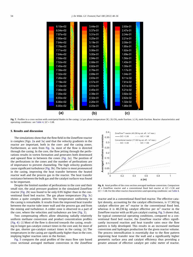
Fig. 7. Profiles in a cross section with centripetal blades in the casing: (a) gas phase temperature (K); (b) CH4 mole fraction; (c) H2 mole fraction. Reactor characteristics andoperating conditions: see Table 4, S/C = 1.68.
0
0.05
0.1
0.15
0.2
0.25
0.3
0.35
0.4
0 0.2 0.4 0.6 0.8 1z (m)
Ave
rage
d m
etha
ne c
onve
rsio
n S/C = 3.36 S/C = 1.68
S/C = 3.36 S/C = 1.68
ZoneFlow™ reactor (40.236 kg cat. eff. / m3 reac.)
Conventional reactor (17.302 kg cat. eff. / m3 reac.)
Fig. 8. Axial profiles of the cross section averaged methane conversion. Comparisonof a ZoneFlow reactor and a conventional fixed bed reactor at S/C = 3.36 andS/C = 1.68. For the other reactor characteristics and operating conditions: see Table 4.
54 J. De Wilde, G.F. Froment / Fuel 100 (2012) 48–56
5. Results and discussion
The simulations show that the flow field in the ZoneFlow reactoris complex (Figs. 2a and 3a) and that the velocity gradients in thereactor are important, both in the core- and the casing zones.Furthermore, as seen from Fig. 3a, most of the flow is directedthrough the casing. In the core, the flow jetting through the perfo-rations results in vortex formation and generates both downwardand upward flow in between the cones (Fig. 2a). The position ofthe perforations in the cones and the number of perforations areof importance to prevent channeling. The high velocity gradientscause significant turbulence (Fig. 3b). The latter is most pronouncedin the casing, improving the heat transfer between the heatedreactor wall and the process gas in the reactor. The heat transferresistance between the bulk gas and the catalyst surfaces was foundto be important.
Despite the limited number of perforations in the core and theirsmall size, the axial pressure gradient in the simulated ZoneFlowreactor (Fig. 2b) was found to be only 0.9% higher than in the con-ventional fixed bed reactor. The gas phase temperature (Fig. 3c)shows a quite complex pattern. The temperature uniformity inthe casing is remarkable. It results from the improved heat transferbetween the reactor tube inner wall and the process gas and fromthe mixing and turbulence. A colder zone is observed in a part ofthe core, where the velocities and turbulence are low (Fig. 3).
Two compensating effects allow obtaining radially relativelyuniform methane conversion and product concentration profiles(Fig. 4): (i) Most of the flow is directed towards the casing, result-ing in longer gas-catalyst contact times in the core and, for most ofthe gas, shorter gas-catalyst contact times in the casing. (ii) Thetemperatures in the casing are significantly higher than in the core,implying higher reaction rates in the former.
Fig. 5 compares the axial profiles of the mass flow rate basedcross sectional averaged methane conversion in the ZoneFlow
reactor and in a conventional fixed bed reactor. The effective cata-lyst density, accounting for the catalyst effectiveness, is 17.302 kgcatalyst effective per m3 reactor in the conventional fixed bed,whereas it is 40.236 kg catalyst effective per m3 reactor in theZoneFlow reactor with an 80 lm catalyst coating. Fig. 5 shows that,for typical commercial operating conditions, compared to a con-ventional fixed bed reactor, the ZoneFlow reactor offers signifi-cantly increased reaction and heat transfer rates once the flowpattern is fully developed. This results in an increased methaneconversion and hydrogen production for the given reactor volume.The process intensification is essentially due to the flow patternimproving heat transfer near the wall and a significantly highergeometric surface area and catalyst efficiency thus providing agreater amount of effective catalyst per cubic meter of reactor.

Fig. 9. Profiles in a cross section with centripetal blades in the casing: (a) net rate CH4 () Cþ 2H2 (adapted scale); (b) net rate COþ H2 () CþH2O (adapted scale); (c) netrate of coke formation accounting for CH4 () Cþ 2H2 and COþH2 () Cþ H2O (adapted scale). Reactor characteristics and operating conditions: see Table 4, S/C = 1.68.Upper side of the cones shown. Reaction rates in [kmol/(m2 s)]. Negative value indicates safe operation, i.e. no net coke formation.
-5.5E-08
-5.0E-08
-4.5E-08
-4.0E-08
-3.5E-08
-3.0E-08
-2.5E-08
-2.0E-08
-1.5E-08
0 0.2 0.4 0.6 0.8 1z (m)A
vera
ged
over
all n
et ra
te o
f cok
e fo
rmat
ion
[km
ole
/ (s2
sur
face
* s)
]
S/C = 3.36S/C = 1.68
Fig. 10. Axial profiles of the cross section averaged net rate of coke formation in aZoneFlow reactor at different steam-to-carbon ratios. Negative value indicates safeoperation, i.e. no net coke formation. Reactor characteristics and other operatingconditions: see Table 4.
J. De Wilde, G.F. Froment / Fuel 100 (2012) 48–56 55
To highlight the effect of increased heat transfer rates, a compari-son between a conventional fixed bed and a ZoneFlow reactor withequal effective catalyst densities is also made in Fig. 5. The asymp-totic behavior, reached after a 30 cm inlet zone, shows a clearly im-proved performance of the ZoneFlow reactor, exclusively due tothe intensified heat transfer between the reactor tube inner walland the process gas. Comparison of the heat transfer in the tworeactors requires the heat transfer in the ZoneFlow reactor to beexpressed in the same terms as those in the fixed bed reactor. Thisinvolves the calculation of a mass flow rate based cross sectionalaveraged gas temperature in the ZoneFlow reactor and the relatedcoefficient of heat transfer between the reactor tube inner wall andthe gas. The latter is found to be roughly 15% higher in the Zone-Flow reactor than in the fixed bed reactor.
From Fig. 5, it is seen that the methane conversion reached after1 m in the fixed bed reactor is reached after 0.6 m in the ZoneFlowreactor with equal effective catalyst bed density than the fixed bedreactor and after 0.25 m in the ZoneFlow reactor with higher effec-tive catalyst bed density. Hence, for identical operating conditions,the reactor volume can be reduced by 40%, respectively 75% byusing a ZoneFlow reactor.
The coking data shown in Fig. 6 reveal that the cracking ofmethane and the gasification of coke by hydrogen are the domi-nant reactions. The latter is one to two orders of magnitude fasterthan the Boudouard reaction. It also shows that there is no net cokeformation in the reactor at a steam-to-carbon ratio of 3.36 which ishigh.
Figs. 7 and 9 summarize the ZoneFlow reactor performance inmethane steam reforming at a steam-to-carbon ratio of 1.68. Figs.8 and 10 compare respectively the axial profiles of the cross section
averaged methane conversion and net rate of coke formation atS/C = 3.36 and S/C = 1.68. In the ZoneFlow reactor, lowering thesteam-to-carbon ratio results in a 14% lower methane conversionand a more uniform temperature profile in the reactor. Becausemore methane is fed, the hydrogen production is slightlyincreased. The advantages of the ZoneFlow reactor resulting fromthe flow pattern and the increased catalyst effectiveness are main-tained at lower steam-to-carbon ratios. The evaluation of thepotential for coke formation (Figs. 9 and 10) shows that, even at
56 J. De Wilde, G.F. Froment / Fuel 100 (2012) 48–56
a steam-to-carbon ratio of 1.68, the coke gasification easily equalsthe coke formation, even in the vicinity of the heated wall.
6. Conclusions
The ZoneFlow reactor optimizes the heat transfer near the wallvia relatively higher velocities in the casing and by directing theflow towards and away from the reactor wall. Furthermore, it al-lows increasing the effective amount of catalyst per unit reactorvolume via a higher geometric surface area and an increased cata-lyst efficiency. The ZoneFlow reactor also optimizes the flow distri-bution and the residence time distribution in the reactor, achievinga shorter residence time in the relatively hotter casing than in thecore of the reactor. The 3D simulations reveal a performance that issuperior to that of conventional fixed bed reactors both in terms ofconversion and coke formation.
References
[1] Trimm DL. The formation and removal of coke from nickel catalyst. Catal Rev-Sci Eng 1997;16:155–89.
[2] Bartholomew CH. Carbon deposition in steam reforming and methanation.Catal Rev-Sci Eng 1982;24:67–112.
[3] Rostrup-Nielsen JR. Catalytic steam reforming. In: Anderson J, Boudart M,editors. Catalysis science and technology, vol. 5, Berlin: Springer; 1984.
[4] [a] Snoeck JW, Froment GF, Fowles M. Filamentous carbon formation andgasification: thermodynamics, driving force, nucleation, and steady-stategrowth. J Catal 1997;169:240–9;[b] Snoeck JW, Froment GF, Fowles M. Kinetic study of the carbon filamentformation by methane cracking on a nickel catalyst. J Catal 1997;169:250–62.
[5] [a] Xu JG, Froment GF. Methane steam reforming, methanation and water-gasshift: I. Intrinsic kinetics. AICHE J 1989;35:88–96;[b] Xu JG, Froment GF. Methane steam reforming: II. Diffusional limitationsand reactor simulation. AICHE J 1989;35:97–103.
[6] Feinstein JJ. Patent: publ. no. EP1773492 (A2); 2007.[7] Tribute Creations LLC. Advanced Hydrogen and Syngas Reforming with
ZoneFlow� Catalytic Reactors. Technical white paper book; 2011.[8] Froment GF, Bischoff KB, De Wilde J. Chemical reactor analysis and design. 3rd
ed. Wiley; 2010.[9] Spalding DB. Concentration fluctuations in a round turbulent free jet. J. Chem.
Eng. Sci. 1971;26:95–107.[10] Hinze J Turbulence. An introduction to its mechanism and theory. New
York: McGraw-Hill; 1959.[11] Schlichting H. Boundary-layer theory. 7th ed. New York: McGraw-Hill; 1979.[12] Jayatilleke CLV. The influence of Prandtl number and surface roughness on the
resistance of the laminar sublayer to momentum and heat transfer. Prog HeatMass Transfer 1969;1:193–329.
[13] Viegas JR, Rubesin MW, Horstman CC. Technical report AIAA-85-0180. AIAA23rd Aerospace Sciences Meeting. Reno, Nevada; 1985.
[14] Siegel R, Howell J. Thermal radiation heat transfer. 2nd ed. Hemisphere Publ.Corp.; 1981. 3rd ed. Taylor & Francis; 1992.
[15] Jones WP, Launder BE. The prediction of laminarization with a two-equationmodel of turbulence. Int J Heat Mass Transf 1972;15:301–14.
[16] Launder BE, Spalding DB. Mathematical models ofturbulence. London: Academic Press; 1972.
[17] Launde BE, Sharma BI. Application of the energy-dissipation model ofturbulence to the calculation of flow near a spinning disc. Lett Heat MassTransf 1974;1:131–7.
[18] Snoeck JW, Froment GF, Fowles M. Steam/CO2 reforming of methane. carbonfilament formation by the Boudouard reaction and gasification by CO2, by H2,and by steam: kinetic study. Ind Eng Chem Res 2002;41:4252–65.
[19] Snoeck JW, Froment GF, Fowles M. Kinetic evaluation of carbon formation insteam/CO2-natural gas reformers. Influence of the catalyst activity andalkalinity. Int J Chem Reac Eng 2003;1:A7.
[20] Patankar SV. Numerical heat transfer and fluid flow. Taylor & Francis; 1980.