Computation Method in Failure Analysis of Mechanically Fastened Joints at Layered Composites
7
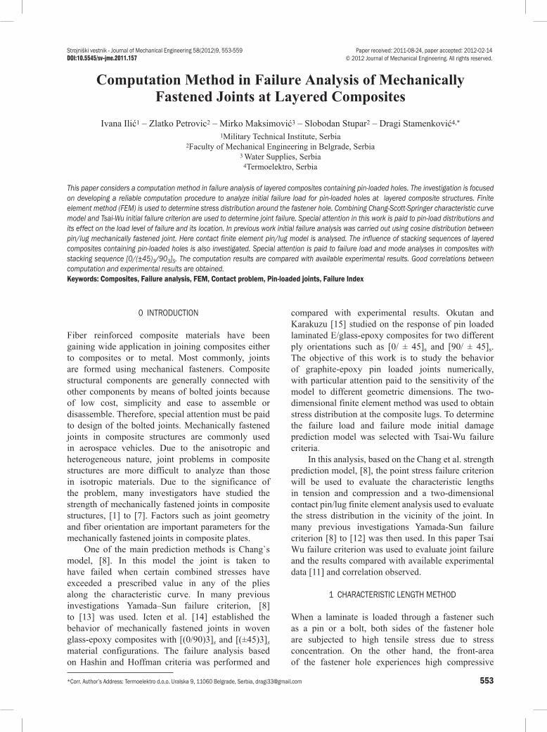
*Corr. Author’s Address: Termoelektro d.o.o. Uralska 9, 11060 Belgrade, Serbia, [email protected] 553 Strojniški vestnik - Journal of Mechanical Engineering 58(2012)9, 553-559 Paper received: 2011-08-24, paper accepted: 2012-02-14 DOI:10.5545/sv-jme.2011.157 © 2012 Journal of Mechanical Engineering. All rights reserved. 0 INTRODUCTION Fiber reinforced composite materials have been gaining wide application in joining composites either to composites or to metal. Most commonly, joints are formed using mechanical fasteners. Composite structural components are generally connected with other components by means of bolted joints because of low cost, simplicity and ease to assemble or disassemble. Therefore, special attention must be paid to design of the bolted joints. Mechanically fastened joints in composite structures are commonly used in aerospace vehicles. Due to the anisotropic and heterogeneous nature, joint problems in composite structures are more difficult to analyze than those in isotropic materials. Due to the significance of the problem, many investigators have studied the strength of mechanically fastened joints in composite structures, [1] to [7]. Factors such as joint geometry and fiber orientation are important parameters for the mechanically fastened joints in composite plates. One of the main prediction methods is Chang`s model, [8]. In this model the joint is taken to have failed when certain combined stresses have exceeded a prescribed value in any of the plies along the characteristic curve. In many previous investigations Yamada–Sun failure criterion, [8] to [13] was used. Icten et al. [14] established the behavior of mechanically fastened joints in woven glass-epoxy composites with [(0/90)3] s and [(±45)3] s material configurations. The failure analysis based on Hashin and Hoffman criteria was performed and compared with experimental results. Okutan and Karakuzu [15] studied on the response of pin loaded laminated E/glass-epoxy composites for two different ply orientations such as [0/ ± 45] s and [90/ ± 45] s . The objective of this work is to study the behavior of graphite-epoxy pin loaded joints numerically, with particular attention paid to the sensitivity of the model to different geometric dimensions. The two- dimensional finite element method was used to obtain stress distribution at the composite lugs. To determine the failure load and failure mode initial damage prediction model was selected with Tsai-Wu failure criteria. In this analysis, based on the Chang et al. strength prediction model, [8], the point stress failure criterion will be used to evaluate the characteristic lengths in tension and compression and a two-dimensional contact pin/lug finite element analysis used to evaluate the stress distribution in the vicinity of the joint. In many previous investigations Yamada-Sun failure criterion [8] to [12] was then used. In this paper Tsai Wu failure criterion was used to evaluate joint failure and the results compared with available experimental data [11] and correlation observed. 1 CHARACTERISTIC LENGTH METHOD When a laminate is loaded through a fastener such as a pin or a bolt, both sides of the fastener hole are subjected to high tensile stress due to stress concentration. On the other hand, the front-area of the fastener hole experiences high compressive Computation Method in Failure Analysis of Mechanically Fastened Joints at Layered Composites Ilić, I. – Petrovic, Z. – Maksimović, M. – Stupar, S. – Stamenković, D. Ivana Ilić 1 – Zlatko Petrovic 2 – Mirko Maksimović 3 – Slobodan Stupar 2 – Dragi Stamenković 4,* 1 Military Technical Institute, Serbia 2 Faculty of Mechanical Engineering in Belgrade, Serbia 3 Water Supplies, Serbia 4 Termoelektro, Serbia This paper considers a computation method in failure analysis of layered composites containing pin-loaded holes. The investigation is focused on developing a reliable computation procedure to analyze initial failure load for pin-loaded holes at layered composite structures. Finite element method (FEM) is used to determine stress distribution around the fastener hole. Combining Chang-Scott-Springer characteristic curve model and Tsai-Wu initial failure criterion are used to determine joint failure. Special attention in this work is paid to pin-load distributions and its effect on the load level of failure and its location. In previous work initial failure analysis was carried out using cosine distribution between pin/lug mechanically fastened joint. Here contact finite element pin/lug model is analysed. The influence of stacking sequences of layered composites containing pin-loaded holes is also investigated. Special attention is paid to failure load and mode analyses in composites with stacking sequence [0/(±45) 3 /90 3 ] S . The computation results are compared with available experimental results. Good correlations between computation and experimental results are obtained. Keywords: Composites, Failure analysis, FEM, Contact problem, Pin-loaded joints, Failure Index
-
Upload
khudhayer1970 -
Category
Documents
-
view
44 -
download
0
description
Computation Method in Failure Analysis of MechanicallyFastened Joints at Layered Composites
Transcript of Computation Method in Failure Analysis of Mechanically Fastened Joints at Layered Composites
*Corr. Author’s Address: Termoelektro d.o.o. Uralska 9, 11060 Belgrade, Serbia, [email protected] 553
Strojniški vestnik - Journal of Mechanical Engineering 58(2012)9, 553-559 Paper received: 2011-08-24, paper accepted: 2012-02-14DOI:10.5545/sv-jme.2011.157 © 2012 Journal of Mechanical Engineering. All rights reserved.
0 INTRODUCTION
Fiber reinforced composite materials have been gaining wide application in joining composites either to composites or to metal. Most commonly, joints are formed using mechanical fasteners. Composite structural components are generally connected with other components by means of bolted joints because of low cost, simplicity and ease to assemble or disassemble. Therefore, special attention must be paid to design of the bolted joints. Mechanically fastened joints in composite structures are commonly used in aerospace vehicles. Due to the anisotropic and heterogeneous nature, joint problems in composite structures are more difficult to analyze than those in isotropic materials. Due to the significance of the problem, many investigators have studied the strength of mechanically fastened joints in composite structures, [1] to [7]. Factors such as joint geometry and fiber orientation are important parameters for the mechanically fastened joints in composite plates.
One of the main prediction methods is Chang`s model, [8]. In this model the joint is taken to have failed when certain combined stresses have exceeded a prescribed value in any of the plies along the characteristic curve. In many previous investigations Yamada–Sun failure criterion, [8] to [13] was used. Icten et al. [14] established the behavior of mechanically fastened joints in woven glass-epoxy composites with [(0/90)3]s and [(±45)3]s material configurations. The failure analysis based on Hashin and Hoffman criteria was performed and
compared with experimental results. Okutan and Karakuzu [15] studied on the response of pin loaded laminated E/glass-epoxy composites for two different ply orientations such as [0/ ± 45]s and [90/ ± 45]s. The objective of this work is to study the behavior of graphite-epoxy pin loaded joints numerically, with particular attention paid to the sensitivity of the model to different geometric dimensions. The two-dimensional finite element method was used to obtain stress distribution at the composite lugs. To determine the failure load and failure mode initial damage prediction model was selected with Tsai-Wu failure criteria.
In this analysis, based on the Chang et al. strength prediction model, [8], the point stress failure criterion will be used to evaluate the characteristic lengths in tension and compression and a two-dimensional contact pin/lug finite element analysis used to evaluate the stress distribution in the vicinity of the joint. In many previous investigations Yamada-Sun failure criterion [8] to [12] was then used. In this paper Tsai Wu failure criterion was used to evaluate joint failure and the results compared with available experimental data [11] and correlation observed.
1 CHARACTERISTIC LENGTH METHOD
When a laminate is loaded through a fastener such as a pin or a bolt, both sides of the fastener hole are subjected to high tensile stress due to stress concentration. On the other hand, the front-area of the fastener hole experiences high compressive
Computation Method in Failure Analysis of Mechanically Fastened Joints at Layered Composites
Ilić, I. – Petrovic, Z. – Maksimović, M. – Stupar, S. – Stamenković, D.Ivana Ilić1 – Zlatko Petrovic2 – Mirko Maksimović3 – Slobodan Stupar2 – Dragi Stamenković4,*
1Military Technical Institute, Serbia 2Faculty of Mechanical Engineering in Belgrade, Serbia
3 Water Supplies, Serbia 4Termoelektro, Serbia
This paper considers a computation method in failure analysis of layered composites containing pin-loaded holes. The investigation is focused on developing a reliable computation procedure to analyze initial failure load for pin-loaded holes at layered composite structures. Finite element method (FEM) is used to determine stress distribution around the fastener hole. Combining Chang-Scott-Springer characteristic curve model and Tsai-Wu initial failure criterion are used to determine joint failure. Special attention in this work is paid to pin-load distributions and its effect on the load level of failure and its location. In previous work initial failure analysis was carried out using cosine distribution between pin/lug mechanically fastened joint. Here contact finite element pin/lug model is analysed. The influence of stacking sequences of layered composites containing pin-loaded holes is also investigated. Special attention is paid to failure load and mode analyses in composites with stacking sequence [0/(±45)3/903]S. The computation results are compared with available experimental results. Good correlations between computation and experimental results are obtained.Keywords: Composites, Failure analysis, FEM, Contact problem, Pin-loaded joints, Failure Index

Strojniški vestnik - Journal of Mechanical Engineering 58(2012)9, 553-559
554 Ilić, I. – Petrovic, Z. – Maksimović, M. – Stupar, S. – Stamenković, D.
stress. Furthermore, as the applied load increases and laminate deforms the contact surface between the fastener and the laminate changes.
A practical method considered to predict the failure load of composite joints with the least amount of testing is the characteristic length method. This method was proposed by Whitney and Nuismer [16], and has been developed by Chang et al. [10] and [11]. It is still used for the failure analysis of composite joints, [17]. In the characteristic length method, two parameters, i.e. compressive and tensile characteristic length should be determined by the stress analysis associated with the results of bearing and tensile tests on the laminates with and without hole. Once the characteristic lengths are determined, an artificial curve connecting the compressive and tensile characteristic lengths named characteristic curve is assumed, [8]. Failure of a joint is evaluated on the characteristic curve and not on the edge of the fastener hole. In this method the joint is taken to have failed when certain combined stresses have exceeded a prescribed value in any of the plies along the characteristic curve.
In order to evaluate the strength of composite pinned joints, Fig. 1, the stress distribution along a characteristic dimension around the hole must first be evaluated. The conditions for failure can then be predicted with the aid of an appropriate failure criterion. In this investigation the Tsai-Wu failure criterion was used for this analysis. This criterion can be written as [18]:
( . )
,F I F F F F
F F F= + + + +
+ + +1 1 2 2 6 6 11 1
2
22 22
66 62
12 1 22
σ σ σ σ
σ σ σ σ
FX X
FX Xt c t c
1 111 1 1
= + = −, ,
FY Y
FYYt c t c
2 221 1 1
= + =, - , (1)
F FS
F6 66 2 120 1 0= = =, , ,
where F.I is failure index, σi (i = 1, 2, 6) are stress components with respect to material principal axes and Xt,c, Yt,c are longitudinal and transverse tensile/compressive strengths of a unidirectional lamina and S is the ply shear strength. In this model, failure is expected to occur when the value of F.I is greater than or equal to unity.
The characteristic curve is an artificial curve made of compressive and tensile characteristic lengths.
Since the characteristic lengths are determined just for pure compression and tension, other combined failure modes are evaluated on the characteristic curve.
A popular method to construct the characteristic curve is proposed by Chang, Scott and Springer [8]. The characteristic curve, Fig. 2, is expressed as follows:
r D R R Rc ot oc tθ θ( ) = + + −( )/ cos ,2 0 (2)
where Roc and Rot are compressive and tensile characteristic lengths, respectively. The angle θ is measured counterclockwise or clockwise from the loaded direction toward the sides of the fastener hole as shown in Fig. 2.
Fig. 1. Geometry of the composite plate with a circular hole, subjected to pin
Fig. 2. Characteristic curve schematic diagram
The ultimate failure of a joint is generally divided into three modes depending on the failure location, θf [8].
0 ≤ θf ≤ 15° Bearing mode, 30 ≤ θf ≤ 60° Shear-out mode, (3) 75 ≤ θf ≤ 90° Net-tension mode.
There are in general three main failure modes: net tension (N-T), shear out (S) and bearing (B) as shown in Fig. 3. Net tension and shear out modes are catastrophic and result from excessive tensile and shear stresses. The bearing mode is local failure

Strojniški vestnik - Journal of Mechanical Engineering 58(2012)9, 553-559
555Computation Method in Failure Analysis of Mechanically Fastened Joints at Layered Composites
and progressive, and related to compressive failure. Net tension and shear out modes can be avoided by increasing the end distance (e) and width (W) of the structural part for a given thickness but bearing failure cannot be avoided by any modification of the geometry.
Fig. 3. Illustration of three basic failure modes
2 FAILURE LOADS OF MECHANICALLY FASTENED JOINTS
To determine failure load of mechanically fastened joint the procedure is composed of stress analysis and failure analysis using adequate initial failure criteria along the characteristic curve.
The strategy for the finite element modeling of the joints is the same as in the finite element model of the laminate for bearing tests shown in Fig. 5. Nonlinear finite element analysis for the joints composite structural components [19] is conducted by MSC/NASTRAN, [20]. Interface between fasteners and laminates is modeled by the slide line contact element provided by the software. The slide line element in MSC/NASTRAN was adopted to simulate the contact between the pins and the laminates. The pin and the laminate were modeled using CQUAD4 shell elements.
Force was applied to the pin as a uniformly distributed load. A typical finite element model of the mechanically fastened joint is shown in Fig. 4.
Fig. 4. Finite element model of the mechanical fastened joint
In this paper the problem of mechanically fastened joints of a laminated composite plate with frictional contact conditions is analyzed. Coulomb friction law is used and the contact constraints are
handled by extended interior penalty methods. The perturbed variation principle is adopted to treat the non-differential term due to the Coulomb friction. The computed results by our formulations are compared with the results of the experiment [21] to [23]. Here fatigue life estimation of these structural components can be included using procedure [24].
3 NUMERICAL VERIFICATION
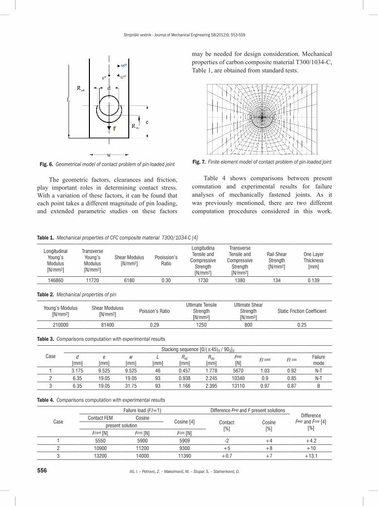
To validate computation procedure of mechanically fastened joints numerical examples are included. Geometry properties of a mechanically fastened joint at composite structure are shown in Fig. 5. The finite element model of the contact problem of pin-loaded joint is shown in Fig. 6. Lug and pin are made from CFC composite and steel materials [25], respectively. Mechanical properties of these materials are given in Tables 1 and 2. For the purpose of comparison, failure analysis of mechanically fastened joints is carried out also using cosine load distribution. Here, specimens made from carbon type composite material T300/1034-C, with stacking sequence [0/(±45)3/903]s are considered.
In this investigation, Tsai Wu failure criteria are used in numerical analyses for predicting the failure behavior. The results of this analysis are shown in Tables 3 and 4 and Figs. 8 to 15. In these tables, it is seen that numerical and experimental results are similar.
Figs. 8 to 15 illustrates in detail, the failure mode of the composite material in Case 1, (Table 3). In this case net-tension (N-T) failure mode is evident.
Fig. 5. Geometry properties of mechanically fastened joints at composites
Strojniški vestnik - Journal of Mechanical Engineering 58(2012)9, 553-559
556 Ilić, I. – Petrovic, Z. – Maksimović, M. – Stupar, S. – Stamenković, D.
Fig. 6. Geometrical model of contact problem of pin-loaded joint
The geometric factors, clearances and friction, play important roles in determining contact stress. With a variation of these factors, it can be found that each point takes a different magnitude of pin loading, and extended parametric studies on these factors
may be needed for design consideration. Mechanical properties of carbon composite material T300/1034-C, Table 1, are obtained from standard tests.
Fig. 7. Finite element model of contact problem of pin-loaded joint
Table 4 shows comparisons between present comutation and experimental results for failure analyses of mechanically fastened joints. As it was previously mentioned, there are two different computation procedures considered in this work.
Table 1. Mechanical properties of CFC composite material T300/1034-C [4]
Longitudinal Young’s Modulus [N/mm2]
Transverse Young’s Modulus [N/mm2]
Shear Modulus [N/mm2]
Pooission’s Ratio
Longitudina Tensile and
Compressive Strength [N/mm2]
Transverse Tensile and
Compressive Strength [N/mm2]
Rail Shear Strength [N/mm2]
One Layer Thickness
[mm]
146860 11720 6180 0.30 1730 1380 134 0.139
Table 2. Mechanical properties of pin
Young’s Modulus[N/mm2]
Shear Moduluss[N/mm2]
Poisson’s RatioUltimate Tensile
Strength[N/mm2]
Ultimate Shear Strength[N/mm2]
Static Friction Coefficient
210000 81400 0.29 1250 800 0.25
Table 3. Comparisons computation with experimental results
CaseStacking sequence [0/(±45)3 / 903]S
d[mm]
e[mm]
w[mm]
L[mm]
Rot[mm]
Roc[mm]
Fexp
[N]FI cont FI cos Failure
mode1 3.175 9.525 9.525 46 0.457 1.778 5670 1.03 0.92 N-T2 6.35 19.05 19.05 93 0.938 2.245 10340 0.9 0.85 N-T3 6.35 19.05 31.75 93 1.166 2.395 13110 0.97 0.87 B
Table 4. Comparisons computation with experimental results
Case
Failure load (F.I=1) Difference Fexp and F present solutionsDifference
Fexp and Fcos [4] [%]
Contact FEM CosineCosine [4] Contact
[%]Cosine
[%]present solution
Fcont [N] Fcos [N] Fcos [N]1 5550 5900 5909 -2 +4 +4.22 10900 11200 9300 +5 +8 +103 13200 14000 11390 +0.7 +7 +13.1

Strojniški vestnik - Journal of Mechanical Engineering 58(2012)9, 553-559
557Computation Method in Failure Analysis of Mechanically Fastened Joints at Layered Composites
Fig. 8. Distributions of F.I at composite lug for experimental failure load (Case 1, N-T failure mode, contact (F=567 daN)
Fig. 9. Distributions of F.I at composite lug for experimental failure load (Case 1, N-T failure mode, cosine (F= 567 daN)
Fig. 10. Distribution of F.I along characteristic curve for experimental failure load (Case 1), contact (F= 567 daN)
Fig. 11. Distribution of F.I along characteristic curve for experimental failure load (Case 1), cosine (F= 567 daN)
Fig. 12. Distributions of F.I at composite lug for failure load (Case 1: N-T failure mode), contact (F= 555 daN)
Fig. 13. Distributions of F.I at composite lug for failure load (Case 1: N-T failure mode), cosine (F= 590 daN)
Fig. 14. Distribution of F.I along characteristic curve for failure load (Case 1), contact (F= 555 daN)
Fig. 15. Distribution of F.I along characteristic curve for failure load (Case 1), cosine (F= 590 daN)

Strojniški vestnik - Journal of Mechanical Engineering 58(2012)9, 553-559
558 Ilić, I. – Petrovic, Z. – Maksimović, M. – Stupar, S. – Stamenković, D.
These two methods are based on: (1) combining contact finite element method for stress analysis in conjunction with Tsai-Wu failure criteria for initial failure analysis and (2) combining cosine load distribution method with Tsai-Wu failure criteria for initial failure analysis.
Clearly, the present contact finite element method in conjunction with Tsai-Wu failure criteria gives the best match to experimental results, (Table 4), while the present cosine load distribution method with Tsai Wu criterion is comparable to results from reference [11]. Results in reference [11] are obtained combining cosine load distribution method in conjunction with Yamada-Sun failure criteria.
Coulomb friction law is used and the contact constraints are handled by extended interior penalty methods. The perturbed variation principle is adopted to treat the non-differential term due to the coulomb friction. The computed results by the previous formulation are compared with experimental results. Good agreement between computation and experimental results is obtained.
4 CONCLUSIONS
In this work a numerical study on the failure load and failure mode investigations of pin loaded composite joints are presented. In the numerical study, a Tsai-Wu failure criterion is used to predict the failure load and failure mode. Special attention is paid to failure load and mode analyses in composites with stacking sequence [0/(±45)3/903]S. For the verification of the proposed computation method, composite laminated joints with various ratios of width-to-hole diameter examined and compared with the test results. It can be seen that the results obtained numerically and experimentally are close to each other. Failure loads of the joints with bearing (B) or net-tension (N-T) modes are the same in both, the present numerical method and the test-based conventional method. Summarizing the results, it is shown that the proposed numerical method in this work based on combining the contact finite element method for stress analysis in conjunction with Tsai-Wu failure criteria for the initial failure analysis predicts the strength of composite joints under pin loading within the maximum of 5% difference from the test results.
The computed results by considered formulations are compared with experimental results in the case of a single hole and agree well.
5 ACKNOWLEDGMENTS
This work was financially supported by the Ministry of Science and Technological Developments of Serbia under Projects OI-174001 and TR-34028.
6 REFERENCES
[1] Dano, M.L., Gendron, G., Piccard, A. (2000). Stress and failure analysis of mechanically fastened joints in composite laminates. Composite Structures, vol. 50, no. 3, p. 287.296.
[2] Lessard, L.B., Shokrieh, M.M. (1995). Two-dimensional modeling of composite pinned-joint failure. Journal of Composite Materials, vol. 29, no. 5, p. 671-697, DOI:10.1177/002199839502900507.
[3] Aktas, A., Karakuzu, R. (1999). Failure analysis of two-dimensional carbon-epoxy composite plate pinned joint, Mechanics of Composite Materials and Structures. vol. 6, no. 4, p. 347-361.
[4] Icten, B.M., Karakuzu, R. (2002). Progressive failure analysis of pin-loaded carbon-epoxy woven composite plates. Composites Science and Technology, vol. 62, no. 9, p. 1259-1271, DOI:10.1016/S0266-3538(02)00071-4.
[5] Camanho P.P., Matthews, F.L. (1999). A progressive damage model for mechanically fastened joints in composite laminates. Journal of Composite Materials, vol. 33, no. 24, p. 2248-2280, DOI:10.1177/002199839903302402.
[6] Okutan, B., Karakuzu, R. (2002). The failure strength of pin-loaded multidirectional fiber-glass reinforced epoxy laminate. Journal of Composite Materials, vol. 36, no. 24, p. 2695-2712, DOI:10.1177/002199802761675502.
[7] Lin, H.J., Tsai, C.C. (1995). Failure analysis of bolted connections of composites with drilled and moulded in hole. Composite Structures, vol. 30, no. 3, p. 159-168, DOI:10.1016/0263-8223(94)00040-9.
[8] Chang, F.K., Scott, R.A., Springer, G.S. (1982). Strength of mechanically fastened composite joints.Journal of Composite Materials, vol. 16, no. 6, p. 470-494, DOI:10.1177/002199838201600603.
[9] Maksimovic S. (2007). Post-buckling and failure analysis of axially compressed composite panels using FEM. Scientific Technical Review, vol. 57, no. 3-4, p. 43-48.
[10] Chang, F.K. (1986). The effect of pin load distribution on the strength of pin loaded holes in laminated composites. Journal of Composite Materials, vol. 20, no. 4, p. 401-408, DOI:10.1177/002199838602000407.
[11] Chang, F.K., Scott, R.A., Springer, G.S. (1984). Failure of composite laminates containing pin loaded holes-method of solution. Journal of Composite Materials, vol. 18, no. 3, p. 255-278, DOI:10.1177/002199838401800305.
[12] Maksimović, S. (1990). Some computational and experimental aspects of the optimal design process of
Strojniški vestnik - Journal of Mechanical Engineering 58(2012)9, 553-559
559Computation Method in Failure Analysis of Mechanically Fastened Joints at Layered Composites
composite structures. Composite Structures, vol. 16. no. 1-3, p. 237-258, DOI:10.1016/0263-8223(90)90074-O.
[13] Wu, T.J., Hahn, T. (1998). The bearing strength of E-glass/vinyl-ester composites fabricated by Vartm.Composites Science and Technology, vol. 58, no. 9, p. 1519-1529, DOI:10.1016/S0266-3538(97)00180-2.
[14] Icten, B.M., Okutan, B., Karakuzu, R. (2003). Failure strength of woven glass fiber-epoxy composite pinned joint. Journal of Composite Materials, vol. 37, no. 15, p. 1337-1351, DOI:10.1177/0021998303034307.
[15] Okutan, B., Karakuzu, R. (2003). The strength of pinned joints in laminated composite plates. Composites Science and Technology, vol. 63, no. 6, p. 893-905, DOI:10.1016/S0266-3538(02)00313-5.
[16] Whitney, J.M., Nuismer, R.J. (1974). Stress fracture criteria for laminated composites containing stress concentration. Journal of Composite Materials, vol. 8, no. 3, p. 253-265, DOI:10.1177/002199837400800303.
[17] Whitworth, H.A., Othieno, M., Barton, O. (2003). Failure analysis of composite pin loaded joints. Composite Structures, vol. 59, no. 2, p. 261-266, DOI:10.1016/S0263-8223(02)00056-9.
[18] Okutan, B. (2002). The effects of geometric parameters on the failure strength for pin-loaded multi-directional fiber-glass reinforced epoxy laminate, Composites Part B: Engineering, vol. 33, no. 8, p. 567-578, DOI: 10.1016/S1359-8368(02)00054-9.
[19] Djordjevic Z., Maksimovic S., Ilic I., (2011). Dynamics Analysis of Hybrid Aluminum/Composite Shafts, Scientific Technical Review, vol. 58, no. 2, pp. 3-7.
[20] MSC/NASTRAN, Theoretical Manuals (2000), MSC Software, Santa Ana.
[21] Pierron, F., Cerisier, F. (2000). A numerical and experimental study of woven composite pin-joints, Journal of Composite Materials, vol. 34, no. 12, p. 1028-1054.
[22] Maikuma, H., Kobomura, K. (1993). Bearing strength and damage progress for PAN-based and pitch based carbon fiber composites, Journal of Composite Materials, vol. 27, no. 18, p. 1739-1761, DOI:10.1177/002199839302701803.
[23] Okutan, B., Aslan, Z., Karakuzu, R. (2001). A study of the effects of various geometric parameters on the failure strength of pin-loaded wovenglass- fiber reinforced epoxy laminate, Composites Science and Technology, vol. 61, no. 10, p. 1491-1497, DOI: 10.1016/S0266-3538(01)00043-4..
[24] Stamenković D., Maksimović K., Nikolić-Stanojević V., Maksimović S., Stupar S., Vasović I. (2010). Fatigue Life Estimation of Notched Structural Components, Strojniški vestnik - Journal of Mechanical Engineering, vol. 56, no. 12, p. 846-852.
[25] Chen, D.-C., Chen, W.-J., Lin, J.-Y., Jheng, M.-W., Chen, J.-M. (2010). Finite Element Analysis of Superplastic Blow-Forming of Ti-6Al-4V Sheet into Closed Ellip-Cylindrical Die. International Journal of Simulation Modeling, vol. 9, no. 1, p. 17-27, DOI:10.2507/IJSIMM09(1)2.137.