Compressive strength and microstructural properties of ...framcos.org/FraMCoS-7/11-09.pdf ·...
7
Fracture Mechanics of Concrete and Concrete Structures - High Performance, Fiber Reinforced Concrete, Special Loadings and Structural Applications- B. H. Oh, et al. (eds) ⓒ 2010 Korea Concrete Institute, ISBN 978-89-5708-182-2
Transcript of Compressive strength and microstructural properties of ...framcos.org/FraMCoS-7/11-09.pdf ·...
Compressive strength and microstructural properties of light weight high strength cement mortar reinforced with eloxal
J. Hemanth
Akshaya Institute of Technology, Karnataka, INDIA
ABSTRACT: An investigation was carried out to evaluate the results of the compressive strength of high strength light weight eloxal reinforced cement mortar subject to short term loads. An experimental method similar to the one proposed by the author on chilled aluminum-quartz reinforced metal matrix composite was used. Eloxal (in the solid slag form) is a waste obtained during the production of aluminum in the plant. It is mainly of aluminum oxide, SiO2, CaO, MgO and other substances. It’s a hard substance, having sufficient strength with additive properties and bonds very rapidly. Eloxal reinforced cement mortar in the present investigation are tested for its compressive and microstructural behavior. Data were obtained pertaining to compressive strength, role of moisture and drying effects. Deformation under compressive load was studied to provide insight into the internal behavior and failure mechanism of light weight eloxal reinforced cement mortar. To analyze the mode of failure under compression, distribution of eloxal particles in cement mortar and the deformation behavior, several optical and Scanning Electron Microscope (SEM) photographs were taken to study the mechanism. Results of the tests of eloxal reinforced cement mortar are compared with unreinforced cement mortar and information obtained else where in earlier tests of normal weight cement mortar. Structural composite materials offer an excellent opportunity to produce components that achieve weight savings and improved properties. The eloxal particles (dispersoid) added to cement mortar in the present investigation is varied from 20 to 40 wt%. in steps of 10 wt.%. The resulting composite blocks cast were tested for their properties.
1 INTRODUCTION
Lightweight concrete composites were used successfully for many years for structural members and elements in buildings and bridges. One of the earliest applications in North America was in the construction of cement mortar ships during World War-I [1]. Through the years, by judicious selection of the lightweight sand and careful proportioning, semi-lightweight cement mortars having high compressive strengths have been made [2]. Although such strength is not necessary in many structural applications, there are advantages to the use of very high strength lightweight cement concrete in such applications as offshore drilling platforms. Such light weight concrete has greater buoyancy and thus is easier to tow in shallow waters, and less excavation is required in construction of the dry dock compared to heavier structures. There is one instance where such lightweight concrete have been used for oil drilling platforms in the Arctic [3]. In addition to its lighter weight, which permits savings in dead load and so reduces the cost of both super structure and foundations, this concrete is more resistant to fire and provides better heat and sound insulation than concrete of normal density [4-6]. For
lightweight concrete structures, as for structures of normal weight concrete, there is a well-established trend toward using higher compressive strengths. This permits the use of smaller member sizes, which in turn permits further reduction in dead load with attendant cost savings, and extends the practical range of span as well [7-9].
Useful information has been available to the structural engineer on the engineering properties of high-strength lightweight cement concrete composites. The main purposes of the work described in this paper were to gain insight into the compressive behavior of high-strength light weight cement mortar reinforced with eloxal. The work of this paper is aimed at establishing the compressive characteristics of eloxal reinforced light weight high strength composite and the study is similar to the one by the author of this paper for the mechanical and microstructural behavior of chilled aluminum alloy-quartz particulate composite [10].
A comprehensive bibliography listing publications on normal and lightweight high-strength concrete for the period from 1930-1979 was published by Carrasquillo and others [11]. References dealing specifically with lightweight high strength concrete were relatively low. Beginning in the late 1950s,
Fracture Mechanics of Concrete and Concrete Structures -High Performance, Fiber Reinforced Concrete, Special Loadings and Structural Applications- B. H. Oh, et al. (eds)
ⓒ 2010 Korea Concrete Institute, ISBN 978-89-5708-182-2
significant research was carried out at the Portland cement association. From these studies, Shideler [12] reported on means of production and properties of light weight concretes. Similarly, Hanson [13] reported research on the shear strength of lightweight concrete beams. Further, Karr, Hanson and Capell [14] reported test results relating to the axial stress strain response and flexural stress distribution in members using lightweight concrete. Wang and others [15] reported properties of lightweight concrete with high compressive strengths.
It is very important to note that, most of the engineering properties of concrete are dependent on the moisture content and moisture distribution in the specimen. In addition, presence of humidity is needed for the continuing hydration of the cement. In other words, the duration and magnitude of strength development are longer and larger, respectively, in a wet cured concrete than in a concrete that is kept in a low reheat environment. The strength finally stops increasing after the concrete dries out completely [16-20]. There is, however, an important exception to this rule; namely, that compressive strength of a concrete specimen is higher when the specimen is dry or a surface layer is dry than if the same specimen were in a fully or surface saturated condition [21,22].
2 EXPERIMENTAL PROCEDURE
2.1 Composition of the matrix material and the dispersoid
Chemical composition of normal Portland cement (matrix) ASTM type 1 (by Birla, India) is given in Table 1.
Table 1. Chemical composition of normal portland cement, ASTM type 1.
SiO2 CaO Al2O3 Fe2O3 MgO SO3 Na2O K2O
22.02 62.76 3.99 2.76 3.30 3.01 0.49 0.54
Some of the important thermo-physical properties
of eloxal are as follows: Density:1600 kg/m
3, Hardness: Rc 78, Melting
point: 680 oC and Youngs Modulus: 75 GPa
Size distribution of the dispersoid: 3.72 to 7.8 mm, Structure: Hexagon close packed
Coefficient of thermal expansion : 0.12 .(data obtained from National Aluminum Laboratories, India [23])
Eloxal (dispersoid) available from the aluminum industry is in the form of a hard solid slag and this is reduced to the required size into the granular form using a ball mill. Before adding, the eloxal was prepared by washing it with water and thus the soluble NaOH and other substances were removed.
Finally the solid eloxal was dried in an oven at 105 0C for 2 hours. The eloxal gradation is as follows:
passing sieve no: 2 and retained sieve no: 4. Eloxal waste is obtained during the production of
aluminum in the plant produced by means of electrolysis or limited oxidation processing of metal plates in the electrolyte solution. It is mainly a mixture of aluminum oxide, silicon, magnesium, calcium and other substances. It’s an industrial waste from the aluminum industry and usage of it has not been made yet because it contains silicon and calcium. The structure of eloxal is closely packed hexagonal particles [23]. The thermo-physical properties of eloxal are studied both in the powder form, slag form and after extrusion into bars. The present composite developed using eloxal as the dispersoid has the properties like rapid hardening, light weight, low thermal coefficient of expansion along with good mechanical properties [24,25]. Extensive research has been carried out on using these composites for strengthening; however, information about their durability and recycling of waste material as the reinforcement is still lacking [26-27].
In this investigation eloxal particles from 20 to 40 wt.% in steps of 10 wt.%, were dispersed in the matrix. Chemical composition of eloxal (dispersoid) is given in Table 2.
Table 2. Chemical composition of the dispersoid (eloxal).
Al2O3 SiO2 MgO CaO Na2O Al(OH)3
48.21 29.82 3.32 15.83 1.21 1.61
2.2 Mix Proportions and Casting Procedure
The cement-sand ratios and water-cement ratios used in the present investigation were 1:3 respectively. The sand grading is shown in Table 3. The mix proportion in the present investigation is obtained by varying the cement content from 300 to 700 kg/m
3 in steps of 100
kg/m3. The casting procedure consisted of mixing
dry, predetermined quantities of graded sand and cement for about three minutes. Water was then added slowly and the mixing continued for another minute. Dry eloxal particles (size 3.72 to 7.8 mm) were slowly and continuously added as the mixing continued. Mixing was done by a medium sized Hobart mixing machine of planetary mixing action. The resulting mix was used to prepare compressive (152*305 mm cylinders, ASTM C 109) testing specimens. Finally the prepared specimens were compacted and leveled and left to cure. The specimens were de-molded after 24 hours and moist cured in a water bath at room temperature for 7, 14, 21 28, 35, 42 and 49 days before testing. A series of three cement mortar mixtures were made, containing 20%, 30% and 40 wt.% eloxal particles (dispersoid) respectively. Thus the mix chiefly consists of the
Proceedings of FraMCoS-7, May 23-28, 2010
hThD ∇−= ),(J (1)
The proportionality coefficient D(h,T) is called moisture permeability and it is a nonlinear function of the relative humidity h and temperature T (Bažant & Najjar 1972). The moisture mass balance requires that the variation in time of the water mass per unit volume of concrete (water content w) be equal to the divergence of the moisture flux J
J•∇=∂
∂−
t
w (2)
The water content w can be expressed as the sum
of the evaporable water we (capillary water, water vapor, and adsorbed water) and the non-evaporable (chemically bound) water wn (Mills 1966, Pantazopoulo & Mills 1995). It is reasonable to assume that the evaporable water is a function of relative humidity, h, degree of hydration, αc, and degree of silica fume reaction, αs, i.e. we=we(h,αc,αs) = age-dependent sorption/desorption isotherm (Norling Mjonell 1997). Under this assumption and by substituting Equation 1 into Equation 2 one obtains
nscw
s
ew
c
ew
hh
Dt
h
h
ew
&&& ++∂
∂
∂
∂
=∇•∇+∂
∂
∂
∂
− αα
αα
)(
(3)
where ∂we/∂h is the slope of the sorption/desorption isotherm (also called moisture capacity). The governing equation (Equation 3) must be completed by appropriate boundary and initial conditions.
The relation between the amount of evaporable water and relative humidity is called ‘‘adsorption isotherm” if measured with increasing relativity humidity and ‘‘desorption isotherm” in the opposite case. Neglecting their difference (Xi et al. 1994), in the following, ‘‘sorption isotherm” will be used with reference to both sorption and desorption conditions. By the way, if the hysteresis of the moisture isotherm would be taken into account, two different relation, evaporable water vs relative humidity, must be used according to the sign of the variation of the relativity humidity. The shape of the sorption isotherm for HPC is influenced by many parameters, especially those that influence extent and rate of the chemical reactions and, in turn, determine pore structure and pore size distribution (water-to-cement ratio, cement chemical composition, SF content, curing time and method, temperature, mix additives, etc.). In the literature various formulations can be found to describe the sorption isotherm of normal concrete (Xi et al. 1994). However, in the present paper the semi-empirical expression proposed by Norling Mjornell (1997) is adopted because it
explicitly accounts for the evolution of hydration reaction and SF content. This sorption isotherm reads
( ) ( )( )
( ) ( )⎥⎥
⎦
⎤
⎢⎢
⎣
⎡
⎥⎥⎥
⎦
⎤
⎢⎢⎢
⎣
⎡
−
−∞
+
−∞
−=
1110
,1
110
11,
1,,
hcc
ge
scK
hcc
ge
scG
sch
ew
αα
αα
αα
αααα
(4)
where the first term (gel isotherm) represents the physically bound (adsorbed) water and the second term (capillary isotherm) represents the capillary water. This expression is valid only for low content of SF. The coefficient G1 represents the amount of water per unit volume held in the gel pores at 100% relative humidity, and it can be expressed (Norling Mjornell 1997) as
( ) ss
s
vgkc
c
c
vgk
scG αααα +=,1
(5)
where k
cvg and k
svg are material parameters. From the
maximum amount of water per unit volume that can fill all pores (both capillary pores and gel pores), one can calculate K1 as one obtains
( )1
110
110
11
22.0188.00
,1
−⎟⎠
⎞⎜⎝
⎛−∞
⎥⎥⎥
⎦
⎤
⎢⎢⎢
⎣
⎡⎟⎠
⎞⎜⎝
⎛−∞
−−+−
=
hcc
ge
hcc
geGs
ssc
w
scK
αα
αα
αα
αα
(6)
The material parameters k
cvg and k
svg and g1 can
be calibrated by fitting experimental data relevant to free (evaporable) water content in concrete at various ages (Di Luzio & Cusatis 2009b).
2.2 Temperature evolution
Note that, at early age, since the chemical reactions associated with cement hydration and SF reaction are exothermic, the temperature field is not uniform for non-adiabatic systems even if the environmental temperature is constant. Heat conduction can be described in concrete, at least for temperature not exceeding 100°C (Bažant & Kaplan 1996), by Fourier’s law, which reads
T∇−= λq (7)
where q is the heat flux, T is the absolute temperature, and λ is the heat conductivity; in this
normal mortar in which the eloxal particulates were dispersed. From each batch, specimens for the specific tests were cast and each test result was obtained from an average of at least three repetitions of the same sample. Specimens were tested both under dry and wet conditions and readings were taken after 7, 14, 21, 28, 35,42 and 49 days of curing. Cylinders were selected for the present research because it accentuates the effect of curing on the compressive strength.
Table 3. Sand Gradation (0.1-.19 mm size is fine sand and 1.19-4.76 mm size is coarse sand).
Passing Sieve no.
Retained Sieve no.
Aggregate size (mm)
% Proportion.
8
16
30
50
100
16
30
50
100
Pan
1.18 – 2.37
0.7 – 1.19
0.3 – 0.6
0.15 – 0.3
Less than 0.15
16
30
40
10
5
3 RESULTS AND DISCUSSION
In the following discussion the term ‘cement mortar’
means cement mortar without eloxal particulates (dispersoid); the presence of eloxal in the cement mortar is indicated by the term ‘composite’. Results of the microstructural examination (using optical microscope and SEM) reveal that the shape of pores present, distribution and orientation of eloxal particles determines the compressive behavior of the composite developed. It is observed in the present investigation that, the maximum compressive strength is obtained for composite containing 40 wt.% dispersoid and hence the discussion is based on this composition.
3.1 Effect of Adding Eloxal to Cement Mortar
The effect of adding eloxal to cement mortar as a dispersoid is that, the setting times of the mixture is gradually decreased and the strength is increased as compared with other cement composites. The setting time mainly depends on the setting time of the Portland cement used. According to the data supplied by the manufacturer (Birla super cement) the initial setting time is 140 min. and the final setting time is 230 min. Microstructural studies reveal that, this decreasing effect of setting time and increase in the strength are attributed to slight solving of eloxal near the boundary (between eloxal and cement mortar) forming ettringite and
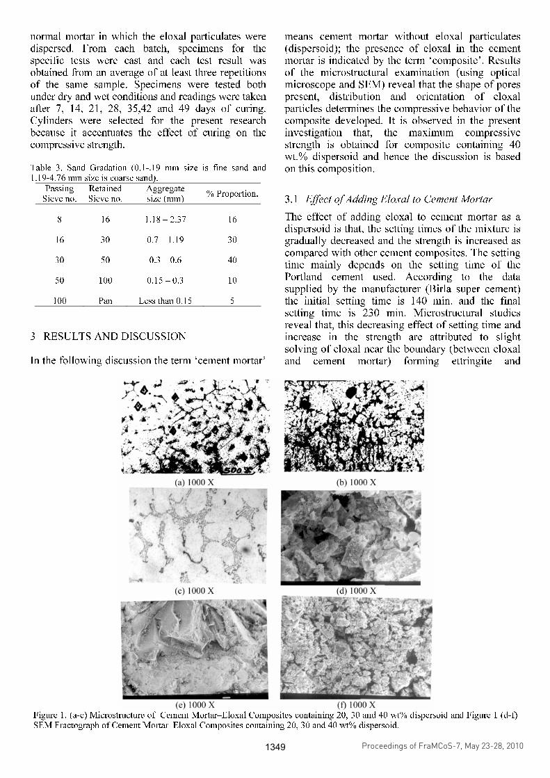
Figure 1. (a-c) Microstructure of Cement Mortar–Eloxal Composites containing 20, 30 and 40 wt% dispersoid and Figure 1 (d-f) SEM Fractograph of Cement Mortar–Eloxal Composites containing 20, 30 and 40 wt% dispersoid.
Proceedings of FraMCoS-7, May 23-28, 2010
hThD ∇−= ),(J (1)
The proportionality coefficient D(h,T) is called moisture permeability and it is a nonlinear function of the relative humidity h and temperature T (Bažant & Najjar 1972). The moisture mass balance requires that the variation in time of the water mass per unit volume of concrete (water content w) be equal to the divergence of the moisture flux J
J•∇=∂
∂−
t
w (2)
The water content w can be expressed as the sum
of the evaporable water we (capillary water, water vapor, and adsorbed water) and the non-evaporable (chemically bound) water wn (Mills 1966, Pantazopoulo & Mills 1995). It is reasonable to assume that the evaporable water is a function of relative humidity, h, degree of hydration, αc, and degree of silica fume reaction, αs, i.e. we=we(h,αc,αs) = age-dependent sorption/desorption isotherm (Norling Mjonell 1997). Under this assumption and by substituting Equation 1 into Equation 2 one obtains
nscw
s
ew
c
ew
hh
Dt
h
h
ew
&&& ++∂
∂
∂
∂
=∇•∇+∂
∂
∂
∂
− αα
αα
)(
(3)
where ∂we/∂h is the slope of the sorption/desorption isotherm (also called moisture capacity). The governing equation (Equation 3) must be completed by appropriate boundary and initial conditions.
The relation between the amount of evaporable water and relative humidity is called ‘‘adsorption isotherm” if measured with increasing relativity humidity and ‘‘desorption isotherm” in the opposite case. Neglecting their difference (Xi et al. 1994), in the following, ‘‘sorption isotherm” will be used with reference to both sorption and desorption conditions. By the way, if the hysteresis of the moisture isotherm would be taken into account, two different relation, evaporable water vs relative humidity, must be used according to the sign of the variation of the relativity humidity. The shape of the sorption isotherm for HPC is influenced by many parameters, especially those that influence extent and rate of the chemical reactions and, in turn, determine pore structure and pore size distribution (water-to-cement ratio, cement chemical composition, SF content, curing time and method, temperature, mix additives, etc.). In the literature various formulations can be found to describe the sorption isotherm of normal concrete (Xi et al. 1994). However, in the present paper the semi-empirical expression proposed by Norling Mjornell (1997) is adopted because it
explicitly accounts for the evolution of hydration reaction and SF content. This sorption isotherm reads
( ) ( )( )
( ) ( )⎥⎥
⎦
⎤
⎢⎢
⎣
⎡
⎥⎥⎥
⎦
⎤
⎢⎢⎢
⎣
⎡
−
−∞
+
−∞
−=
1110
,1
110
11,
1,,
hcc
ge
scK
hcc
ge
scG
sch
ew
αα
αα
αα
αααα
(4)
where the first term (gel isotherm) represents the physically bound (adsorbed) water and the second term (capillary isotherm) represents the capillary water. This expression is valid only for low content of SF. The coefficient G1 represents the amount of water per unit volume held in the gel pores at 100% relative humidity, and it can be expressed (Norling Mjornell 1997) as
( ) ss
s
vgkc
c
c
vgk
scG αααα +=,1
(5)
where k
cvg and k
svg are material parameters. From the
maximum amount of water per unit volume that can fill all pores (both capillary pores and gel pores), one can calculate K1 as one obtains
( )1
110
110
11
22.0188.00
,1
−⎟⎠
⎞⎜⎝
⎛−∞
⎥⎥⎥
⎦
⎤
⎢⎢⎢
⎣
⎡⎟⎠
⎞⎜⎝
⎛−∞
−−+−
=
hcc
ge
hcc
geGs
ssc
w
scK
αα
αα
αα
αα
(6)
The material parameters k
cvg and k
svg and g1 can
be calibrated by fitting experimental data relevant to free (evaporable) water content in concrete at various ages (Di Luzio & Cusatis 2009b).
2.2 Temperature evolution
Note that, at early age, since the chemical reactions associated with cement hydration and SF reaction are exothermic, the temperature field is not uniform for non-adiabatic systems even if the environmental temperature is constant. Heat conduction can be described in concrete, at least for temperature not exceeding 100°C (Bažant & Kaplan 1996), by Fourier’s law, which reads
T∇−= λq (7)
where q is the heat flux, T is the absolute temperature, and λ is the heat conductivity; in this
hydrogranate (3Ca(Fe2O3, Al2O3, H2O) phase, calcium aluminate and calcium silicate both hydrates, that occur by reaction of cement mortar and eloxal, then forming a strong bond between the two (matrix and the dispersoid). The setting time of all cement mortar – eloxal mixes is in accordance with Indian Standards (IS) limits.
3.2 Microsrtuctural observation of the composite
Microstructural studies (Fig. 1, a-c) reveal good bonding and distribution of eloxal particles throughout the matrix (cement mortar) with no interfacial reaction with the matrix (cement mortar) and the dispersoid (eloxal) without any porous formation. This may be one of the reasons for increase in strength and soundness of the composite developed. SEM photograph (Fig. 1, a-c) shows the structure which contains calcium silicates (fibrous phase), portlandite [Ca(OH)2], ettringite (dimple form) and hydrogranate phase (dark phase) [28]. Results of the microstructural observations also supports that, hydration yields a white cover appearance and thus the main structure was formed as a growth of calcium hydroxide and hydrogranate phase among calcium silicate hydrate gels. In figures (1, a-c), the matrix is indicated by an arrow-A and the dispersoid by arrow-B.
Examination of the fracture surface features using SEM of the fractured specimens failed under compression at low magnification to identify the final fracture regions, and at higher magnification to identify regions of micro-crack initiation, early crack
growth and final scale fracture features. Fracture surfaces revealed different topographies for the composite containing different weight percent of eloxal particles. Fracture of the composites containing 20 wt.% dispersoid on macroscopic and microscopic scale exhibited brittle fracture with isolated cracks (see arrow-C) in the matrix (Fig. 1, d). Composites containing 30 wt % dispersoid revealed brittle fracture covered with dimples (see arrow-D) as shown in figure 1 e. Observations of the composite containing 40 wt.% dispersoid revealed large areas of the fracture surface to be covered with a bimodal distribution of dimples (see arrow-E) which is an indication of the mixed mode fracture (Fig. 1, f). However growth of the void is limited by competing and synergistic influence of reinforcing eloxal particles and in the composite microstructure.
3.3 Compressive Strength
All the specimens for compressive strength tests were kept in the moulds for 24 hours, and then cured under different conditions. The curing temperature for all the specimens was maintained at 27
0C. Then
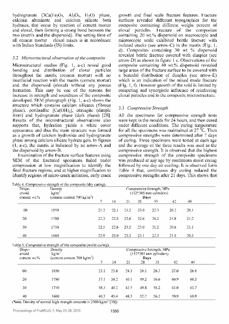
compressive strengths were determined after 7 days of curing. Three specimens were tested at each age and the average of the three results was used as the compressive strength. It is observed that the highest compressive strength of the composite specimens was produced at any age by continuous moist curing followed by one day air cooling. It is observed form Table 4 that, continuous dry curing reduced the compressive strengths after 21 days. This shows that
Table 4. Compressive strength of the composite (dry curing).
Dispe- ersoid content wt.%
Density kg/m3
(cement content 700 kg/m3)
Compressive Strength, MPa (152*305 mm cylinders) Days 7 14 21 28 35 42 49
00 20 30 40
1850 1780 1710 1680
21.2 22.1 23.2 23.0 22.3 20.2 20.1 22.3 22.8 22.6 22.6 20.2 21.8 21.2 22.5 22.6 23.2 23.0 21.2 20.8 21.1 22.9 23.0 23.3 23.1 22.3 21.8 20.3
Table 5. Compressive strength of the composite (moist curing).
Dispe- ersoid content wt.%
Density kg/m3
(cement content 700 kg/m3)
Compressive Strength, MPa (152*305 mm cylinders) Days 7 14 21 28 35 42 49
00 20 30 40
1850 1780 1710 1680
23.1 23.8 24.3 26.1 26.3 27.0 26.8 37.1 38.2 40.1 49.2 56.6 60.9 60.3 38.3 40.2 42.5 49.8 58.2 63.0 62.7 40.3 45.4 48.3 52.7 56.2 70.9 68.9
(Note: Density of normal high strength concrete is 2300 kg/m3 [30])
Proceedings of FraMCoS-7, May 23-28, 2010
hThD ∇−= ),(J (1)
The proportionality coefficient D(h,T) is called moisture permeability and it is a nonlinear function of the relative humidity h and temperature T (Bažant & Najjar 1972). The moisture mass balance requires that the variation in time of the water mass per unit volume of concrete (water content w) be equal to the divergence of the moisture flux J
J•∇=∂
∂−
t
w (2)
The water content w can be expressed as the sum
of the evaporable water we (capillary water, water vapor, and adsorbed water) and the non-evaporable (chemically bound) water wn (Mills 1966, Pantazopoulo & Mills 1995). It is reasonable to assume that the evaporable water is a function of relative humidity, h, degree of hydration, αc, and degree of silica fume reaction, αs, i.e. we=we(h,αc,αs) = age-dependent sorption/desorption isotherm (Norling Mjonell 1997). Under this assumption and by substituting Equation 1 into Equation 2 one obtains
nscw
s
ew
c
ew
hh
Dt
h
h
ew
&&& ++∂
∂
∂
∂
=∇•∇+∂
∂
∂
∂
− αα
αα
)(
(3)
where ∂we/∂h is the slope of the sorption/desorption isotherm (also called moisture capacity). The governing equation (Equation 3) must be completed by appropriate boundary and initial conditions.
The relation between the amount of evaporable water and relative humidity is called ‘‘adsorption isotherm” if measured with increasing relativity humidity and ‘‘desorption isotherm” in the opposite case. Neglecting their difference (Xi et al. 1994), in the following, ‘‘sorption isotherm” will be used with reference to both sorption and desorption conditions. By the way, if the hysteresis of the moisture isotherm would be taken into account, two different relation, evaporable water vs relative humidity, must be used according to the sign of the variation of the relativity humidity. The shape of the sorption isotherm for HPC is influenced by many parameters, especially those that influence extent and rate of the chemical reactions and, in turn, determine pore structure and pore size distribution (water-to-cement ratio, cement chemical composition, SF content, curing time and method, temperature, mix additives, etc.). In the literature various formulations can be found to describe the sorption isotherm of normal concrete (Xi et al. 1994). However, in the present paper the semi-empirical expression proposed by Norling Mjornell (1997) is adopted because it
explicitly accounts for the evolution of hydration reaction and SF content. This sorption isotherm reads
( ) ( )( )
( ) ( )⎥⎥
⎦
⎤
⎢⎢
⎣
⎡
⎥⎥⎥
⎦
⎤
⎢⎢⎢
⎣
⎡
−
−∞
+
−∞
−=
1110
,1
110
11,
1,,
hcc
ge
scK
hcc
ge
scG
sch
ew
αα
αα
αα
αααα
(4)
where the first term (gel isotherm) represents the physically bound (adsorbed) water and the second term (capillary isotherm) represents the capillary water. This expression is valid only for low content of SF. The coefficient G1 represents the amount of water per unit volume held in the gel pores at 100% relative humidity, and it can be expressed (Norling Mjornell 1997) as
( ) ss
s
vgkc
c
c
vgk
scG αααα +=,1
(5)
where k
cvg and k
svg are material parameters. From the
maximum amount of water per unit volume that can fill all pores (both capillary pores and gel pores), one can calculate K1 as one obtains
( )1
110
110
11
22.0188.00
,1
−⎟⎠
⎞⎜⎝
⎛−∞
⎥⎥⎥
⎦
⎤
⎢⎢⎢
⎣
⎡⎟⎠
⎞⎜⎝
⎛−∞
−−+−
=
hcc
ge
hcc
geGs
ssc
w
scK
αα
αα
αα
αα
(6)
The material parameters k
cvg and k
svg and g1 can
be calibrated by fitting experimental data relevant to free (evaporable) water content in concrete at various ages (Di Luzio & Cusatis 2009b).
2.2 Temperature evolution
Note that, at early age, since the chemical reactions associated with cement hydration and SF reaction are exothermic, the temperature field is not uniform for non-adiabatic systems even if the environmental temperature is constant. Heat conduction can be described in concrete, at least for temperature not exceeding 100°C (Bažant & Kaplan 1996), by Fourier’s law, which reads
T∇−= λq (7)
where q is the heat flux, T is the absolute temperature, and λ is the heat conductivity; in this
the method of curing is very important for the strength. In dry curing it is observed that the 49 days control strengths were lower than the 7 days strengths. This implies that the method of curing during the last days before testing is also very important. In other words the compressive strength of the composite is almost sensitive to the moisture distribution in the specimen or in other words strengths of the composite are always greater after lengthy moist curing than after lengthy air curing. This demonstrates that the eloxal reinforced cement mortar reached highest compressive after continuous moist curing. Conversely, dry curing reduces the strength of the composite since bonding does not take place between the dispersoid and the matrix. Table 5 shows the compressive strengths of the composites developed when it is moist cured. It is observed that, for each composite the compressive strength increases as the curing rate increases The reason for the increase of compressive strength of the composite developed is due to the presence of free moisture in the composite. SEM fractographic observations (refer Figs. 1, a-f) of the specimens failed in compressive indicates that, no porous region were found between dispersoid and the matrix and this increases the compressive strength of the composite.
Density tests reveal that the density of the composite developed was 1680 kg/m
3 for composite
containing 700 kg/m3
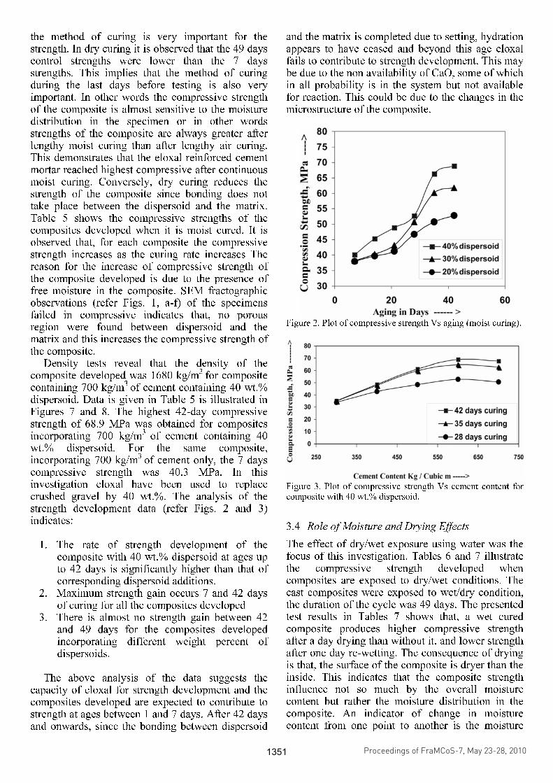
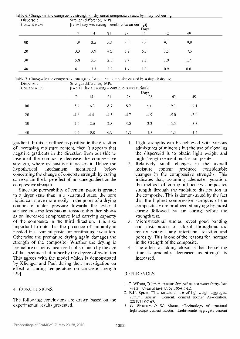
of cement containing 40 wt.% dispersoid. Data is given in Table 5 is illustrated in Figures 7 and 8. The highest 42-day compressive strength of 68.9 MPa was obtained for composites incorporating 700 kg/m
3 of cement containing 40
wt.% dispersoid. For the same composite, incorporating 700 kg/m
3 of cement only, the 7 days
compressive strength was 40.3 MPa. In this investigation eloxal have been used to replace crushed gravel by 40 wt.%. The analysis of the strength development data (refer Figs. 2 and 3) indicates:
1. The rate of strength development of the composite with 40 wt.% dispersoid at ages up to 42 days is significantly higher than that of corresponding dispersoid additions.
2. Maximum strength gain occurs 7 and 42 days of curing for all the composites developed
3. There is almost no strength gain between 42 and 49 days for the composites developed incorporating different weight percent of dispersoids.
The above analysis of the data suggests the
capacity of eloxal for strength development and the composites developed are expected to contribute to strength at ages between 1 and 7 days. After 42 days and onwards, since the bonding between dispersoid
and the matrix is completed due to setting, hydration appears to have ceased and beyond this age eloxal fails to contribute to strength development. This may be due to the non availability of CaO, some of which in all probability is in the system but not available for reaction. This could be due to the changes in the microstructure of the composite.
Figure 2. Plot of compressive strength Vs aging (moist curing).
Figure 3. Plot of compressive strength Vs cement content for composite with 40 wt.% dispersoid.
3.4 Role of Moisture and Drying Effects
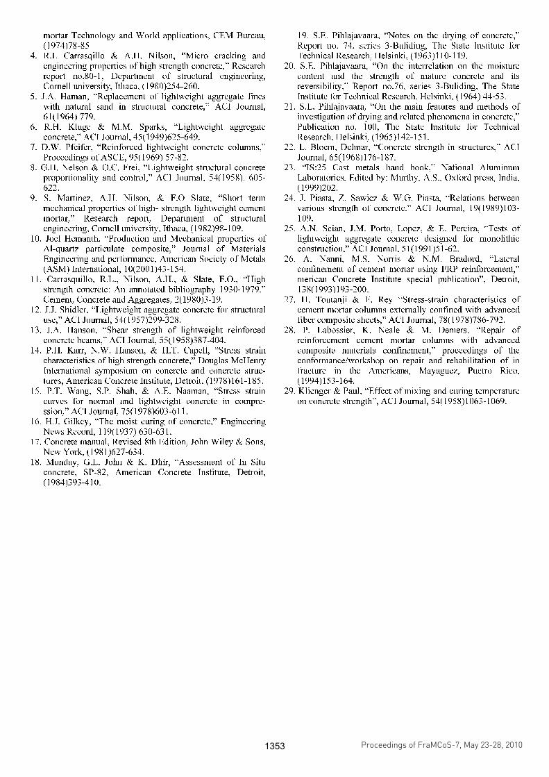
The effect of dry/wet exposure using water was the focus of this investigation. Tables 6 and 7 illustrate the compressive strength developed when composites are exposed to dry/wet conditions. The cast composites were exposed to wet/dry condition, the duration of the cycle was 49 days. The presented test results in Tables 7 shows that, a wet cured composite produces higher compressive strength after a day drying than without it, and lower strength after one day re-wetting. The consequence of drying is that, the surface of the composite is dryer than the inside. This indicates that the composite strength influence not so much by the overall moisture content but rather the moisture distribution in the composite. An indicator of change in moisture content from one point to another is the moisture
Proceedings of FraMCoS-7, May 23-28, 2010
hThD ∇−= ),(J (1)
The proportionality coefficient D(h,T) is called moisture permeability and it is a nonlinear function of the relative humidity h and temperature T (Bažant & Najjar 1972). The moisture mass balance requires that the variation in time of the water mass per unit volume of concrete (water content w) be equal to the divergence of the moisture flux J
J•∇=∂
∂−
t
w (2)
The water content w can be expressed as the sum
of the evaporable water we (capillary water, water vapor, and adsorbed water) and the non-evaporable (chemically bound) water wn (Mills 1966, Pantazopoulo & Mills 1995). It is reasonable to assume that the evaporable water is a function of relative humidity, h, degree of hydration, αc, and degree of silica fume reaction, αs, i.e. we=we(h,αc,αs) = age-dependent sorption/desorption isotherm (Norling Mjonell 1997). Under this assumption and by substituting Equation 1 into Equation 2 one obtains
nscw
s
ew
c
ew
hh
Dt
h
h
ew
&&& ++∂
∂
∂
∂
=∇•∇+∂
∂
∂
∂
− αα
αα
)(
(3)
where ∂we/∂h is the slope of the sorption/desorption isotherm (also called moisture capacity). The governing equation (Equation 3) must be completed by appropriate boundary and initial conditions.
The relation between the amount of evaporable water and relative humidity is called ‘‘adsorption isotherm” if measured with increasing relativity humidity and ‘‘desorption isotherm” in the opposite case. Neglecting their difference (Xi et al. 1994), in the following, ‘‘sorption isotherm” will be used with reference to both sorption and desorption conditions. By the way, if the hysteresis of the moisture isotherm would be taken into account, two different relation, evaporable water vs relative humidity, must be used according to the sign of the variation of the relativity humidity. The shape of the sorption isotherm for HPC is influenced by many parameters, especially those that influence extent and rate of the chemical reactions and, in turn, determine pore structure and pore size distribution (water-to-cement ratio, cement chemical composition, SF content, curing time and method, temperature, mix additives, etc.). In the literature various formulations can be found to describe the sorption isotherm of normal concrete (Xi et al. 1994). However, in the present paper the semi-empirical expression proposed by Norling Mjornell (1997) is adopted because it
explicitly accounts for the evolution of hydration reaction and SF content. This sorption isotherm reads
( ) ( )( )
( ) ( )⎥⎥
⎦
⎤
⎢⎢
⎣
⎡
⎥⎥⎥
⎦
⎤
⎢⎢⎢
⎣
⎡
−
−∞
+
−∞
−=
1110
,1
110
11,
1,,
hcc
ge
scK
hcc
ge
scG
sch
ew
αα
αα
αα
αααα
(4)
where the first term (gel isotherm) represents the physically bound (adsorbed) water and the second term (capillary isotherm) represents the capillary water. This expression is valid only for low content of SF. The coefficient G1 represents the amount of water per unit volume held in the gel pores at 100% relative humidity, and it can be expressed (Norling Mjornell 1997) as
( ) ss
s
vgkc
c
c
vgk
scG αααα +=,1
(5)
where k
cvg and k
svg are material parameters. From the
maximum amount of water per unit volume that can fill all pores (both capillary pores and gel pores), one can calculate K1 as one obtains
( )1
110
110
11
22.0188.00
,1
−⎟⎠
⎞⎜⎝
⎛−∞
⎥⎥⎥
⎦
⎤
⎢⎢⎢
⎣
⎡⎟⎠
⎞⎜⎝
⎛−∞
−−+−
=
hcc
ge
hcc
geGs
ssc
w
scK
αα
αα
αα
αα
(6)
The material parameters k
cvg and k
svg and g1 can
be calibrated by fitting experimental data relevant to free (evaporable) water content in concrete at various ages (Di Luzio & Cusatis 2009b).
2.2 Temperature evolution
Note that, at early age, since the chemical reactions associated with cement hydration and SF reaction are exothermic, the temperature field is not uniform for non-adiabatic systems even if the environmental temperature is constant. Heat conduction can be described in concrete, at least for temperature not exceeding 100°C (Bažant & Kaplan 1996), by Fourier’s law, which reads
T∇−= λq (7)
where q is the heat flux, T is the absolute temperature, and λ is the heat conductivity; in this
gradient. If this is defined as positive in the direction of increasing moisture content, then it appears that negative gradients in the direction from out side to inside of the composite decrease the compressive strength, where as positive increases it. Hence the hypothetical mechanism mentioned below concerning the change of concrete strength by curing can explain the large effect of moisture gradient on the compressive strength.
Since the permeability of cement paste is greater in a dryer state than in a saturated state, the pore liquid can move more easily in the pores of a drying composite under pressure towards the external surface creating less biaxial tension; this then shows as an increased compressive load carrying capacity of the composite in the third direction. It is also important to note that the presence of humidity is needed in a cement paste for continuing hydration. Otherwise the premature drying again damages the strength of the composite. Whether the drying is premature or not is measured not so much by the age of the specimen but rather by the degree of hydration This agrees with the model which is demonstrated by Klienger and Paul during their investigation on effect of curing temperature on concrete strength [29]
4 CONCLUSIONS
The following conclusions are drawn based on the experimental results presented.
1. High strengths can be achieved with various admixtures of minerals but the use of eloxal as the dispersoid is to obtain light weight and high strength cement mortar composite.
2. Relatively small changes in the overall moisture content produced considerable changes in the compressive strengths. This indicates that, assuming adequate hydration, the method of curing influences composites strength through the moisture distribution in the composite. This is demonstrated by the fact that the highest compressive strengths of the composites were produced at any age by moist curing followed by air curing before the strength test.
3. Microstructural studies reveal good bonding and distribution of eloxal throughout the matrix without any interfacial reaction and porosity. This is one of the reasons for increase in the strength of the composite.
4. The effect of adding eloxal is that the setting time is gradually decreased as strength is increased.
REFERENCES
1. C. Wilson, “Cement mortar ship resists sea water thirty-four years,” Cement mortar, 62(1954)5-12.
2. B.H. Spratt, “The structural use of lightweight aggregate cement mortar,” Cement, cement mortar Association, 22(1974)57-63.
3. G. Wischers & W. Manns, “Technology of structural lightweight cement mortar,” Lightweight aggregate cement
Table 6. Changes in the compressive strength of dry cured composite caused by a day wet curing.
Dispersoid Content wt.%
Strength difference, MPa [(air+1 day wet curing – continuous air curing)]
Days 7 14 21 28 35 42 49
00 20 30 40
1.0 3.5 5.3 8.0 8.8 9.1 9.0 3.3 3.9 4.2 5.8 6.3 7.5 7.5 5.8 3.5 2.8 2.4 2.1 1.9 1.7 6.1 3.3 2.2 1.4 1.3 0.9 0.8
Table 7. Changes in the compressive strength of wet cured composite caused by a day air drying.
Dispersoid Content wt.%
Strength difference, MPa [(wet+1 day air curing – continuous wet curing)]
Days 7 14 21 28 35 42 49
00 20 30 40
-5.9 -6.3 -6.7 -8.2 -9.0 -9.1 -9.1 -4.6 -4.4 -4.5 -4.7 -4.9 -5.0 -5.0 -2.0 -2.6 -2.8 -3.0 -3.3 -3.3 -3.3 -0.6 -0.8 -0.9 -1.2 -1.3 -1.3 -1.4
Proceedings of FraMCoS-7, May 23-28, 2010
hThD ∇−= ),(J (1)
The proportionality coefficient D(h,T) is called moisture permeability and it is a nonlinear function of the relative humidity h and temperature T (Bažant & Najjar 1972). The moisture mass balance requires that the variation in time of the water mass per unit volume of concrete (water content w) be equal to the divergence of the moisture flux J
J•∇=∂
∂−
t
w (2)
The water content w can be expressed as the sum
of the evaporable water we (capillary water, water vapor, and adsorbed water) and the non-evaporable (chemically bound) water wn (Mills 1966, Pantazopoulo & Mills 1995). It is reasonable to assume that the evaporable water is a function of relative humidity, h, degree of hydration, αc, and degree of silica fume reaction, αs, i.e. we=we(h,αc,αs) = age-dependent sorption/desorption isotherm (Norling Mjonell 1997). Under this assumption and by substituting Equation 1 into Equation 2 one obtains
nscw
s
ew
c
ew
hh
Dt
h
h
ew
&&& ++∂
∂
∂
∂
=∇•∇+∂
∂
∂
∂
− αα
αα
)(
(3)
where ∂we/∂h is the slope of the sorption/desorption isotherm (also called moisture capacity). The governing equation (Equation 3) must be completed by appropriate boundary and initial conditions.
The relation between the amount of evaporable water and relative humidity is called ‘‘adsorption isotherm” if measured with increasing relativity humidity and ‘‘desorption isotherm” in the opposite case. Neglecting their difference (Xi et al. 1994), in the following, ‘‘sorption isotherm” will be used with reference to both sorption and desorption conditions. By the way, if the hysteresis of the moisture isotherm would be taken into account, two different relation, evaporable water vs relative humidity, must be used according to the sign of the variation of the relativity humidity. The shape of the sorption isotherm for HPC is influenced by many parameters, especially those that influence extent and rate of the chemical reactions and, in turn, determine pore structure and pore size distribution (water-to-cement ratio, cement chemical composition, SF content, curing time and method, temperature, mix additives, etc.). In the literature various formulations can be found to describe the sorption isotherm of normal concrete (Xi et al. 1994). However, in the present paper the semi-empirical expression proposed by Norling Mjornell (1997) is adopted because it
explicitly accounts for the evolution of hydration reaction and SF content. This sorption isotherm reads
( ) ( )( )
( ) ( )⎥⎥
⎦
⎤
⎢⎢
⎣
⎡
⎥⎥⎥
⎦
⎤
⎢⎢⎢
⎣
⎡
−
−∞
+
−∞
−=
1110
,1
110
11,
1,,
hcc
ge
scK
hcc
ge
scG
sch
ew
αα
αα
αα
αααα
(4)
where the first term (gel isotherm) represents the physically bound (adsorbed) water and the second term (capillary isotherm) represents the capillary water. This expression is valid only for low content of SF. The coefficient G1 represents the amount of water per unit volume held in the gel pores at 100% relative humidity, and it can be expressed (Norling Mjornell 1997) as
( ) ss
s
vgkc
c
c
vgk
scG αααα +=,1
(5)
where k
cvg and k
svg are material parameters. From the
maximum amount of water per unit volume that can fill all pores (both capillary pores and gel pores), one can calculate K1 as one obtains
( )1
110
110
11
22.0188.00
,1
−⎟⎠
⎞⎜⎝
⎛−∞
⎥⎥⎥
⎦
⎤
⎢⎢⎢
⎣
⎡⎟⎠
⎞⎜⎝
⎛−∞
−−+−
=
hcc
ge
hcc
geGs
ssc
w
scK
αα
αα
αα
αα
(6)
The material parameters k
cvg and k
svg and g1 can
be calibrated by fitting experimental data relevant to free (evaporable) water content in concrete at various ages (Di Luzio & Cusatis 2009b).
2.2 Temperature evolution
Note that, at early age, since the chemical reactions associated with cement hydration and SF reaction are exothermic, the temperature field is not uniform for non-adiabatic systems even if the environmental temperature is constant. Heat conduction can be described in concrete, at least for temperature not exceeding 100°C (Bažant & Kaplan 1996), by Fourier’s law, which reads
T∇−= λq (7)
where q is the heat flux, T is the absolute temperature, and λ is the heat conductivity; in this
mortar Technology and World applications, CEM Bureau, (1974)78-85
4. R.L Carrasqillo & A.H. Nilson, “Micro cracking and engineering properties of high strength concrete,” Research report no.80-1, Department of structural engineering, Cornell university, Ithaca, (1980)254-260.
5. J.A. Haman, “Replacement of lightweight aggregate fines with natural sand in structural concrete,” ACI Journal, 61(1964) 779.
6. R.H. Kluge & M.M. Sparks, “Lightweight aggregate concrete,” ACI Journal, 45(1949)625-649.
7. D.W. Pfeifer, “Reinforced lightweight concrete columns,” Proceedings of ASCE, 95(1969) 57-82.
8. G.H. Nelson & O.C. Frei, “Lightweight structural concrete proportionality and control,” ACI Journal, 54(1958). 605-622.
9. S. Martinez, A.H. Nilson, & F.O Slate, “Short term mechanical properties of high- strength lightweight cement mortar,” Research report, Department of structural engineering, Cornell university, Ithaca, (1982)98-109.
10. Joel Hemanth, “Production and Mechanical properties of Al-quartz particulate composite,” Journal of Materials Engineering and performance, American Society of Metals (ASM) International, 10(2001)43-154.
11. Carrasquillo, R.L., Nilson, A.H., & Slate, F.O., “High strength concrete: An annotated bibliography 1930-1979,” Cement, Concrete and Aggregates, 2(1980)3-19.
12. J.J. Shidler, “Lightweight aggregate concrete for structural use,” ACI Journal, 54(1957)299-328.
13. J.A. Hanson, “Shear strength of lightweight reinforced concrete beams,” ACI Journal, 55(1958)387-404.
14. P.H. Karr, N.W. Hanson, & H.T. Capell, “Stress strain characteristics of high strength concrete,” Douglas McHenry International symposium on concrete and concrete struc-tures, American Concrete Institute, Detroit, (1978)161-185.
15. P.T. Wang, S.P. Shah, & A.E. Naaman, “Stress strain curves for normal and lightweight concrete in compre-ssion,” ACI Journal, 75(1978)603-611.
16. H.J. Gilkey, “The moist curing of concrete,” Engineering News Record, 119(1937) 630-631.
17. Concrete manual, Revised 8th Edition, John Wiley & Sons, New York, (1981)627-634.
18. Munday, G.L. John & K. Dhir, “Assessment of In Situ concrete, SP-82, American Concrete Institute, Detroit, (1984)393-410.
19. S.E. Pihlajavaara, “Notes on the drying of concrete,” Report no. 74, series 3-Buliding, The State Institute for Technical Research, Helsinki, (1963)110-119.
20. S.E. Pihlajavaara, “On the interrelation on the moisture content and the strength of mature concrete and its reversibility,” Report no.76, series 3-Buliding, The State Institute for Technical Research, Helsinki, (1964) 44-53.
21. S.E. Pihlajavaara, “On the main features and methods of investigation of drying and related phenomena in concrete,” Publication no. 100, The State Institute for Technical Research, Helsinki, (1965)142-151.
22. L. Bloem, Delmar, “Concrete strength in structures,” ACI Journal, 65(1968)176-187.
23. “IS:25 Cast metals hand book,” National Aluminum Laboratories, Edited by: Murthy, A.S., Oxford press, India, (1999)202.
24. J. Piasta, Z. Sawicz & W.G. Piasta, “Relations between various strength of concrete,” ACI Journal, 19(1989)103-109.
25. A.N. Scian, J.M. Porto, Lopez, & E. Pereira, “Tests of lightweight aggregate concrete designed for monolithic construction,” ACI Journal, 51(1991)51-62.
26. A. Nanni, M.S. Norris & N.M. Bradord, “Lateral confinement of cement mortar using FRP reinforcement,” merican Concrete Institute special publication”, Detroit, 138(1993)193-200.
27. H. Toutanji & F. Rey “Stress-strain characteristics of cement mortar columns externally confined with advanced fiber composite sheets,” ACI Journal, 78(1978)786-792.
28. P. Labossier, K. Neale & M. Demers, “Repair of reinforcement cement mortar columns with advanced composite materials confinement,” proceedings of the conformance/workshop on repair and rehabilitation of in fracture in the Americans, Mayaguez, Puetro Rico, (1994)153-164.
29. Klienger & Paul, “Effect of mixing and curing temperature on concrete strength”, ACI Journal, 54(1958)1063-1069.
Proceedings of FraMCoS-7, May 23-28, 2010
hThD ∇−= ),(J (1)
The proportionality coefficient D(h,T) is called moisture permeability and it is a nonlinear function of the relative humidity h and temperature T (Bažant & Najjar 1972). The moisture mass balance requires that the variation in time of the water mass per unit volume of concrete (water content w) be equal to the divergence of the moisture flux J
J•∇=∂
∂−
t
w (2)
The water content w can be expressed as the sum
of the evaporable water we (capillary water, water vapor, and adsorbed water) and the non-evaporable (chemically bound) water wn (Mills 1966, Pantazopoulo & Mills 1995). It is reasonable to assume that the evaporable water is a function of relative humidity, h, degree of hydration, αc, and degree of silica fume reaction, αs, i.e. we=we(h,αc,αs) = age-dependent sorption/desorption isotherm (Norling Mjonell 1997). Under this assumption and by substituting Equation 1 into Equation 2 one obtains
nscw
s
ew
c
ew
hh
Dt
h
h
ew
&&& ++∂
∂
∂
∂
=∇•∇+∂
∂
∂
∂
− αα
αα
)(
(3)
where ∂we/∂h is the slope of the sorption/desorption isotherm (also called moisture capacity). The governing equation (Equation 3) must be completed by appropriate boundary and initial conditions.
The relation between the amount of evaporable water and relative humidity is called ‘‘adsorption isotherm” if measured with increasing relativity humidity and ‘‘desorption isotherm” in the opposite case. Neglecting their difference (Xi et al. 1994), in the following, ‘‘sorption isotherm” will be used with reference to both sorption and desorption conditions. By the way, if the hysteresis of the moisture isotherm would be taken into account, two different relation, evaporable water vs relative humidity, must be used according to the sign of the variation of the relativity humidity. The shape of the sorption isotherm for HPC is influenced by many parameters, especially those that influence extent and rate of the chemical reactions and, in turn, determine pore structure and pore size distribution (water-to-cement ratio, cement chemical composition, SF content, curing time and method, temperature, mix additives, etc.). In the literature various formulations can be found to describe the sorption isotherm of normal concrete (Xi et al. 1994). However, in the present paper the semi-empirical expression proposed by Norling Mjornell (1997) is adopted because it
explicitly accounts for the evolution of hydration reaction and SF content. This sorption isotherm reads
( ) ( )( )
( ) ( )⎥⎥
⎦
⎤
⎢⎢
⎣
⎡
⎥⎥⎥
⎦
⎤
⎢⎢⎢
⎣
⎡
−
−∞
+
−∞
−=
1110
,1
110
11,
1,,
hcc
ge
scK
hcc
ge
scG
sch
ew
αα
αα
αα
αααα
(4)
where the first term (gel isotherm) represents the physically bound (adsorbed) water and the second term (capillary isotherm) represents the capillary water. This expression is valid only for low content of SF. The coefficient G1 represents the amount of water per unit volume held in the gel pores at 100% relative humidity, and it can be expressed (Norling Mjornell 1997) as
( ) ss
s
vgkc
c
c
vgk
scG αααα +=,1
(5)
where k
cvg and k
svg are material parameters. From the
maximum amount of water per unit volume that can fill all pores (both capillary pores and gel pores), one can calculate K1 as one obtains
( )1
110
110
11
22.0188.00
,1
−⎟⎠
⎞⎜⎝
⎛−∞
⎥⎥⎥
⎦
⎤
⎢⎢⎢
⎣
⎡⎟⎠
⎞⎜⎝
⎛−∞
−−+−
=
hcc
ge
hcc
geGs
ssc
w
scK
αα
αα
αα
αα
(6)
The material parameters k
cvg and k
svg and g1 can
be calibrated by fitting experimental data relevant to free (evaporable) water content in concrete at various ages (Di Luzio & Cusatis 2009b).
2.2 Temperature evolution
Note that, at early age, since the chemical reactions associated with cement hydration and SF reaction are exothermic, the temperature field is not uniform for non-adiabatic systems even if the environmental temperature is constant. Heat conduction can be described in concrete, at least for temperature not exceeding 100°C (Bažant & Kaplan 1996), by Fourier’s law, which reads
T∇−= λq (7)
where q is the heat flux, T is the absolute temperature, and λ is the heat conductivity; in this