Compression Connector System - TNB.COMtnblnx3.tnb.com/emAlbum/albums/Color-Keyed...
24
Compression Connector System
Transcript of Compression Connector System - TNB.COMtnblnx3.tnb.com/emAlbum/albums/Color-Keyed...

CompressionConnectorSystem

Step One Preparing the Cable
Wire Stripper shown is Part No. BCS8-40.
Strip the insulation to the proper length sothat conductors can be fully inserted into theconnector barrel.
Strip Length Too Long
Strip Length Too Short
Strip Length Just Right
Strip the insulation carefully to avoid nickingor cutting conductors (wire brush if required).
StrandsCut
NickedStrands
GoodStrip
33
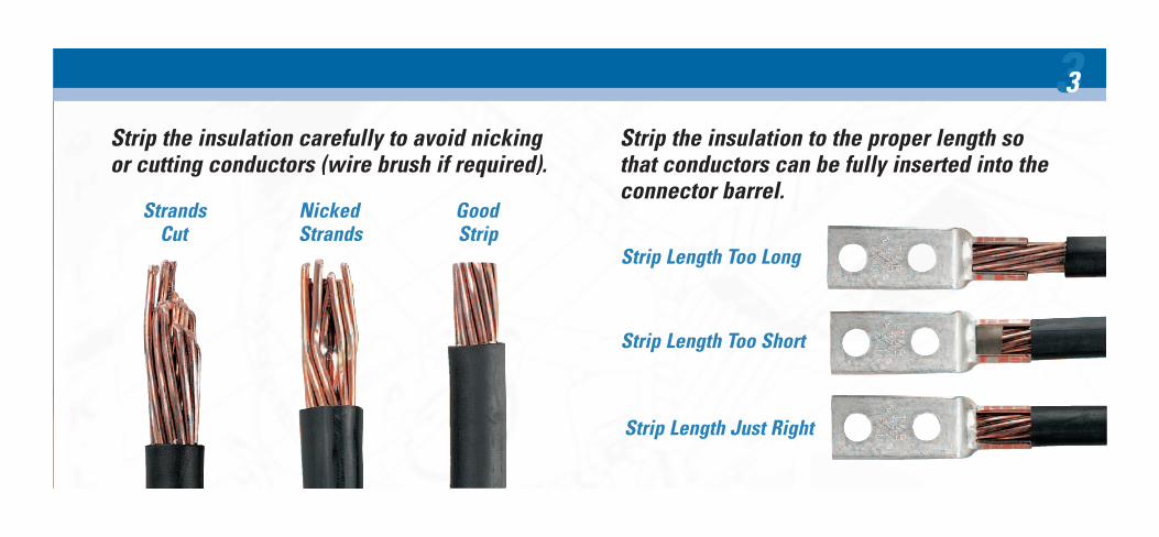
Step Two Determining the Proper Connector

Determine the proper Color-Keyed ® Connectorfor the cable size being used.• Connectors marked with just cable size or CU
should be used on copper conductors only.
• Connectors marked “AL9”*with the cable sizeshould be used on aluminum conductors only.
• Connectors marked “AL9CU” with the cablesize may be used on the aluminum orcopper conductors.
* Aluminum lugs with a “9” indicate 90 oC rating.
Connectors are marked to show cable size.
55
Cable Size

Step Three Choosing Tool and Proper Die
Battpac™ Tool TBM62BSCR shown.
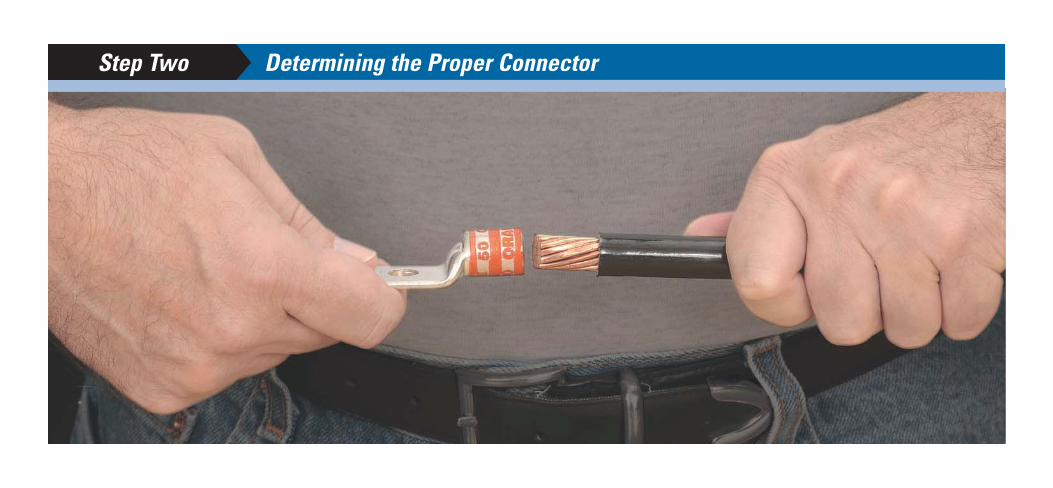
Select the proper installingdie and appropriate tool.T&B Connectors have colored bandsor colored dots that correspond tocolor markings on the dies.
Connectors and dies also have a diecode number marked or stamped onthem. Dies have a code numberengraved in the crimp surface
Colored Codes
Colored BandsDie Code Marking
Colored Strip
Die Code Engraving
77

Locate tool with correctdie in proper positionon connector andactivate tool.T&B Connectors are banded bycolored stripes or engraving toindicate location of die onconnector for compression.
AluminumDie locatedON Bands
CopperDie located
BETWEEN bands
Step Four Installation and Inspection
Battpac™ Battery Powered Compression TBM62BSCR shown.

When properly crimped, the die code number will be embossed on the connector for easy inspection to determine if correct dieand connector combination were used.Thomas & Betts uses “full-width”and “half-width” dies dependenton connector size and tool used.“Half-width” dies are markedwith the letter “H” after thedie code number.
Refer to the instruction sheetsupplied with the connectorsfor information regarding striplength, die selection and numberof compressions required.
When making multiplecrimps, make the first crimpnearest the tongue and worktowards the barrel end.
Barrel
Tongue
1st crimp2nd crimp
Die location for compression Colored bands
Die code embossed
99
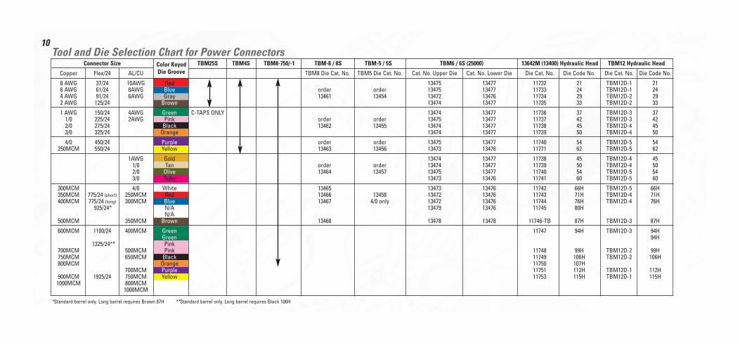
Connector Size TBM25S TBM4S TBM8-750/-1 TBM-8 / 8S TBM-5 / 5S TBM6 / 6S (25000) 13642M (13400) Hydraulic Head TBM12 Hydraulic Head
Copper Flex/24 AL/CU TBM8 Die Cat. No. TBM5 Die Cat. No. Cat. No. Upper Die Cat. No. Lower Die Die Cat. No. Die Code No. Die Cat. No. Die Code No.
8 AWG 37/24 10AWG Red 13475 13477 11732 21 TBM12D-1 216 AWG 61/24 8AWG Blue order order 13475 13477 11733 24 TBM12D-1 244 AWG 91/24 6AWG Gray 13461 13454 13472 13476 11734 29 TBM12D-2 292 AWG 125/24 Brown 13474 13477 11735 33 TBM12D-2 33
1 AWG 150/24 4AWG Green C-TAPS ONLY 13474 13477 11736 37 TBM12D-3 371/0 225/24 2AWG Pink order order 13475 13477 11737 42 TBM12D-3 422/0 275/24 Black 13462 13455 13474 13477 11738 45 TBM12D-4 453/0 325/24 Orange 13474 13477 11739 50 TBM12D-4 50
4/0 450/24 Purple order order 13475 13477 11740 54 TBM12D-5 54250MCM 550/24 Yellow 13463 13456 13473 13476 11771 62 TBM12D-5 62
1AWG Gold 13474 13477 11738 45 TBM12D-4 451/0 Tan order order 13474 13477 11739 50 TBM12D-4 502/0 Olive 13464 13457 13475 13477 11740 54 TBM12D-5 543/0 Ruby 13473 13476 11741 60 TBM12D-5 60
300MCM 4/0 White 13465 13473 13476 11742 66H TBM12D-5 66H350MCM 775/24 (short) 250MCM Red 13466 13458 13472 13476 11743 71H TBM12D-4 71H400MCM 775/24 (long) 300MCM Blue 13467 4/0 only 13472 13476 11744 76H TBM12D-4 76H
925/24* N/A 13479 13476 11745 80HN/A
500MCM 350MCM Brown 13468 13478 13478 11746-TB 87H TBM12D-3 87H
600MCM 1100/24 400MCM Green 11747 94H TBM12D-3 94HGreen 94H
1325/24** Pink700MCM 500MCM Pink 11748 99H TBM12D-2 99H750MCM 650MCM Black 11749 106H TBM12D-2 106H800MCM Orange 11750 107H
700MCM Purple 11751 112H TBM12D-1 112H900MCM 1925/24 750MCM Yellow 11753 115H TBM12D-1 115H1000MCM 800MCM
1000MCM
Tool and Die Selection Chart for Power Connectors
*Standard barrel only. Long barrel requires Brown 87H **Standard barrel only. Long barrel requires Black 106H
Color KeyedDie Groove
10

Connector Size TBM6BSCR/6H TBM62BSCR TBM14BSCR / 14M / 13100A TBM15BSCR / 15I*** 21940 (40 TON)
Code Copper Flex/24 AL/CU Die Cat. No. Die Code No. Die Cat. No. Die Code No. Die Cat. No. Die Code No. Die Cat. No. Die Code No. Die Cat. No. Die Code No.
8 AWG 37/24 10AWG Red 6TON21 21 TBM6221 21 15520 21 15520 216 AWG 61/24 8AWG Blue 6TON24 24 TBM6224 24 15522 24 15522 244 AWG 91/24 6AWG Gray 6TON29 29 TBM6229 29 15527-CK 29 15527-CK 29 11401 292 AWG 125/24 Brown 6TON33 33 TBM6233 33 15528 33 15528 33 11402 331 AWG 150/24 4AWG Green 6TON37 37 TBM6237 37 15513-CK 37 15513-CK 37 11333 37
1/0 225/24 2AWG Pink 6TON42 42 TBM6242 42 15508 42 15508 42H 11334 422/0 275/24 Black 6TON45 45 TBM6245 45 15526 45 15526 45 11405 453/0 325/24 Orange 6TON50 50 TBM6250 50 15530 50 15530 50 11406 504/0 450/24 Purple 6TON54 54 TBM6254 54 15511 54 15511 54H 11407 54H
250MCM 550/24 Yellow 6TON62 62 TBM6262 62 15510-CK 62 15510-CK 62 297-31669-7 621AWG Gold 6TON45 45 TBM6245 45 15526 45 15526 45 11405 45
1/0 Tan 6TON50 50 TBM6250 50 15530 50 15530 50 11406 502/0 Olive 6TON54 54 TBM6254 54 15511 54 15511 54H 11407 543/0 Ruby 6TON60 60 TBM6260 60 15532-CK 60 15532-CK 60 11408 60
300MCM 4/0 White 6TON66 66H TBM6266 66 15534 66H 15534 66H 11409 66350MCM 775/24 (short) 250MCM Red 6TON71 71H TBM6271 71 15514-CK 71H 15514-CK 71H 11363 71400MCM 775/24 (long) 300MCM Blue 6TON76 76H TBM6276 76 15512 76H 15512 76H 11410 76
925/24* N/A 6TON80 80H TBM6280 80 15517 80H 15517 80HN/A 15606 80
500MCM 350MCM Brown 6TON87 87H TBM6287 87 15506 87H 15506 87H 11423 87
600MCM 1100/24 400MCM Green 6TON94 94H 15611 94H 11364 94Green 15536-CK 94H 15536-CK 94H
1325/24** Pink700MCM 500MCM Pink 99H 15505 99H 15505 99H 11424 99750MCM 650MCM Black 106H 15515-CK 106H 15515-CK 106H 74506 106800MCM Orange 107H 15608 107H 11425 107
700MCM Purple 112H 15609 112H 11426 112900MCM 1925/24 750MCM Yellow 115H 15504 115H 15504 115H 11308 1151000MCM 800MCM 15603 125H 11416 125
1000MCM 15602 140H 11418 14015601 150H 11419 150
Tool and Die Selection Chart for Power Connectors
*Standard barrel only. Long barrel requires Brown 87H **Standard barrel only. Long barrel requires Black 106H ***15500 Series dies require 15500-TB adapter. 15500F for full size die to fit TBM151 without adapter
Color KeyedDie Groove
11

12
Conductor Size Code Cable (Flex Cable) Installation
Main Branch 1 Branch 2 Branch 3 H-Tap Color Die Tool # Of Crimps Die Embossing Strip Length Insulating Cover
8-14 (8-14) 8-14 (8-14) - - CHT814-10 Green 15CA37RCH* Group 1 1 37R 1/2" HTC2S
2-6 Str/Sol(2-8) 2-6 Str / Sol (2-8) 8-14 (8-14) 8-14 (8-14) CHT214-9 Brown 15CA71RCH* Group1 1 71R 7/8"
250-2 (4/0-2) 8-14 (8-14) 8-14 (8-14) - CHT250214-8 Purple 15CA80RCH* Group 2 1 80R 1 1/8"HTC40
250-2 (4/0-2) 2-6 Str / Sol (2-8) 8-14 (8-14) - CHT25014-7 Purple 15CA80RCH* Group 2 1 80R 1 1/8"
250-2 (4/0-2) 250-2 (4/0-2) - - CHT2502-6 Purple 15CA80RCH* Group 2 1 80R 13/16"
500-4/0 (350-4/0) 250-1/0 (4/0-1/0) 1 Str 2-6 (1-8) 8-14 (8-14) CHT50010-5 Brown 15612CH Group 2 2 N 1 1/8"
500-4/0 (350-4/0) 500-4/0 (350-4/0) - - CHT50040-4 Brown 15612CH Group 2 2 N 1 1/8"
750-350 (550-500) 4/0-1/0 (250-1/0) 1 Str 2-6 (1-8) 2-14 (2-14) CHT75010-3 Yellow 15620CH Group 2 1 Z 1 1/8" HTC500
750-350 (550-500) 750-350 (550-350) - - CHT750350-2 Yellow 15620CH Group 2 1 Z 1 3/8"
750 (750-500) 350-4/0 STR & FLEX - - CHT75040-11 Yellow 15620CH Group 2 1 Z 1 1/8"
(750-500) (750) (750-500) (350) - - CHT750350-1F White 15620CHF Group 2 1 F 1 1/8" HTC1000
Tool and Die Selection Chart for Copper H-Taps
*Requires optional adapter 15500-TB when used with hydraulic head TBM15I and TBM15BSCR Group 1 = TBM15I, TBM15BSCR, TBM14, TBM14BSCR, 13100A Group 2 = TBM15I, TBM15BSCR

13
*** When using 3 AWG on main and 12 AWG on branch with smart tools and dies, 12 AWG wire must be doubled (hair-pinned) and placed on branch for crimpingGroup 1 = TBM6H / TBM6BSCRGroup 2 = TBM25S, TBM21E and require 2 compressions within each crimp areaGroup 3 = TBM5 / 5S, TBM6 / 6S, TBM8/8S, TBM6H and require 1 compression within each crimp area
Tool and Die Chart for Standard C-TapsCode Wire Comb. Cir. Area Range Group 1 TBM62BSCR TBM8-750 Group 2 Group 3 Insulation Choice
Main Branch 1 C-Tap Color Die Die Die Adhesive Pad Shrink Tubing
12 14 54705 Red 6TON21 TBM6221 -14 1610 10 54710 Blue 6TON24 TBM6224 HS12-68 126 10,12 54715 Gray 6TON29 TBM6229 -8 8,10,12
4 OR 5 8, 10, 12 54720 Brown 6TON33 TBM6233 TBM8-750C206 6, 83 6, 8, 10, 12 *** 54725 Green 6TON37 TBM6237 TBM8-750C2530
4 OR 5 6, 5 HS6-12 6, 8, 10, 12 54730 Pink 6TON42 TBM6242 TBM8-750C25303 5 AC5X34 31 4, 5, 6, 8, 10, 12 54735 Black 6TON45 TBM6245 TBM8-750C35402 4, 53 3, 4
1/0 4, 5, 6, 8, 10, 12 54740 Orange 6TON50 TBM6250 TBM8-750C35401 3, 42 2, 3 HS4-30
2/0 3, 4, 5, 6, 8, 10, 12 54745 Purple 6TON54 TBM6254 TBM8-750C45501/0 2, 31 1, 3
3/0 2, 3, 4, 5, 6, 8, 10, 12 54750 Yellow 6TON62 TBM6262 TBM8-750C45502/0 1, 21/0 1/0, 1
Acco
mm
odat
es th
is R
ange
Acco
mm
odat
es th
is E
ntire
Ran
ge
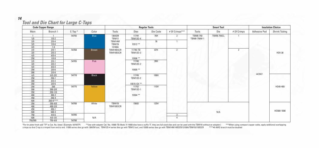
14Tool and Die Chart for Large C-Taps
*For tin plate finish add "TP" to Cat. No. listed (Example: 54755TP) **Use with adapter Cat. No. 15500-TB (Note: If 15500 dies have a suffix "F", they are full sized dies and can be used with the TBM15I without an adapter.) ***When using compact copper cable, apply additional overlappingcrimps so that C-tap is crimped from end to end. 11000 series dies go with 13642M tool, TBM12D-# series dies go with TBM12 tool, and 15500 series dies go with TBM14M/14BSCR/13100A/TBM15I/15BSCR ****#6 AWG branch must be doubled
Code Copper Range Regular Tools Smart Tool Insulation Choice
Main Branch 1 C-Tap * Color Tools Dies Die Code # Of Crimps*** Tools Die # Of Crimps Adhesive Pad Shrink Tubing
1 1 54755 Blue 13642M 11744 76H 2 TBM8-750 TBM8-750CL 11/0 1/0-2 TBM12 TBM12D-4 TBM8-750M-12/0 2/0-4 TBM14M 76 13/0 1/0-6 TBM15I 15512 **4/0 1-8 13100A2/0 2/0-1 54760 Brown TBM14BSCR 11746-TB 87H 2 23/0 3/0-3 TBM15BSCR TBM12D-3 HS4-304/0 4/0-4250 1/0-8 15506 **2/0 2/0-1 54765 Pink 11748 99H3/0 3/0-2 TBM12D-24/0 4/0-4250 3/0-6 15505 **300 2/0-84/0 4/0-2/0 54770 Black 11749 106H AC5X7
250 250-1 TBM12D-2300 4/0-4350 3/0-6 15515-CK **250 250 54775 Yellow 11753 115H HS40-400300 300-3/0 TBM12D-1350 350-1/0400 300-2 15504 **450 250-4500 250-6****350 350-4/0 54780 White TBM15I 15603 125H400 400-2/0 TBM15BSCR450 450-1500 500-2 N/A HS500-1000
750 4/0-6 54785 3500 4/0-1/0 N/A 4
750/500 750-4/0 54790

15
Conductor PropertiesConductors Direct-Current Resistance at 75°C (167°F)
Stranding Overall Copper Aluminum
Size Area Diameter Diameter Area Uncoated Coated
(AWG or kcmil) mm2 Circular mils Quantity mm in. mm in. mm2 in.2 ohm/km ohm/kFT ohm/km ohm/kFT ohm/km ohm/kFT
18 0.823 1620 1 — — 1.02 0.040 0.823 0.001 25.5 7.77 26.5 8.08 42.0 12.818 0.823 1620 7 0.39 0.015 1.16 0.046 1.06 0.002 26.1 7.95 27.7 8.45 42.8 13.1
16 1.31 2580 1 — — 1.29 0.051 1.31 0.002 16.0 4.89 16.7 5.08 26.4 8.0516 1.31 2580 7 0.49 0.019 1.46 0.058 1.68 0.003 16.4 4.99 17.3 5.29 26.9 8.21
14 2.08 4110 1 — — 1.63 0.064 2.08 0.003 10.1 3.07 10.4 3.19 16.6 5.0614 2.08 4110 7 0.62 0.024 1.85 0.073 2.68 0.004 10.3 3.14 10.7 3.26 16.9 5.17
12 3.31 6530 1 — — 2.05 0.081 3.31 0.005 6.34 1.93 6.57 2.01 10.45 3.1812 3.31 6530 7 0.78 0.030 2.32 0.092 4.25 0.006 6.50 1.98 6.73 2.05 10.69 3.25
10 5.261 10380 1 — — 2.588 0.102 5.26 0.008 3.984 1.21 4.148 1.26 6.561 2.0010 5.261 10380 7 0.98 0.038 2.95 0.116 6.76 0.011 4.070 1.24 4.226 1.29 6.679 2.04
8 8.367 16510 1 — — 3.264 0.128 8.37 0.013 2.506 0.764 2.579 0.786 4.125 1.268 8.367 16510 7 1.23 0.049 3.71 0.146 10.76 0.017 2.551 0.778 2.653 0.809 4.204 1.28
6 13.30 26240 7 1.56 0.061 4.67 0.184 17.09 0.027 1.608 0.491 1.671 0.510 2.652 0.8084 21.15 41740 7 1.96 0.077 5.89 0.232 27.19 0.042 1.010 0.308 1.053 0.321 1.666 0.5083 26.67 52620 7 2.20 0.087 6.60 0.260 34.28 0.053 0.802 0.245 0.833 0.254 1.320 0.4032 33.62 66360 7 2.47 0.097 7.42 0.292 43.23 0.067 0.634 0.194 0.661 0.201 1.045 0.3191 42.41 83690 19 1.69 0.066 8.43 0.332 55.80 0.087 0.505 0.154 0.524 0.160 0.829 0.253

16
Conductor Properties (Continued)Conductors Direct-Current Resistance at 75°C (167°F)
Stranding Overall Copper Aluminum
Size Area Diameter Diameter Area Uncoated Coated
(AWG or kcmil) mm2 Circular mils Quantity mm in. mm in. mm2 in.2 ohm/km ohm/kFT ohm/km ohm/kFT ohm/km ohm/kFT
1/0 53.49 105600 19 1.89 0.074 9.45 0.372 70.41 0.109 0.399 0.122 0.415 0.127 0.660 0.2012/0 67.43 133100 19 2.13 0.084 10.62 0.418 88.74 0.137 0.3170 0.0967 0.329 0.101 0.523 0.1593/0 85.01 167800 19 2.39 0.094 11.94 0.470 111.9 0.173 0.2512 0.0766 0.2610 0.0797 0.413 0.1264/0 107.2 211600 19 2.68 0.106 13.41 0.528 141.1 0.219 0.1996 0.0608 0.2050 0.0626 0.328 0.100
250 — 37 2.09 0.082 14.61 0.575 168 0.260 0.1687 0.0515 0.1753 0.0535 0.2778 0.0847300 — 37 2.29 0.090 16.00 0.630 201 0.312 0.1409 0.0429 0.1463 0.0446 0.2318 0.0707350 — 37 2.47 0.097 17.30 0.681 235 0.364 0.1205 0.0367 0.1252 0.0382 0.1984 0.0605
400 — 37 2.64 0.104 18.49 0.728 268 0.416 0.1053 0.0321 0.1084 0.0331 0.1737 0.0529500 — 37 2.95 0.116 20.65 0.813 336 0.519 0.0845 0.0258 0.0869 0.0265 0.1391 0.0424600 — 61 2.52 0.099 22.68 0.893 404 0.626 0.0704 0.0214 0.0732 0.0223 0.1159 0.0353
700 — 61 2.72 0.107 24.49 0.964 471 0.730 0.0603 0.0184 0.0622 0.0189 0.0994 0.0303750 — 61 2.82 0.111 25.35 0.998 505 0.782 0.0563 0.0171 0.0579 0.0176 0.0927 0.0282800 — 61 2.91 0.114 26.16 1.030 538 0.834 0.0528 0.0161 0.0544 0.0166 0.0868 0.0265
900 — 61 3.09 0.122 27.79 1.094 606 0.940 0.0470 0.0143 0.0481 0.0147 0.0770 0.02351000 — 61 3.25 0.128 29.26 1.152 673 1.042 0.0423 0.0129 0.0434 0.0132 0.0695 0.0212
FPN: The construction information is per NEMA WC8-1992 or ANSI/UL 1581-1998. The resistance is calculated per National Bureau of StandardsHandbook 100, dated 1966, and Handbook 109, dated 1972.
70–625 TABLESNATIONAL ELECTRICAL CODE, 2002 Edition
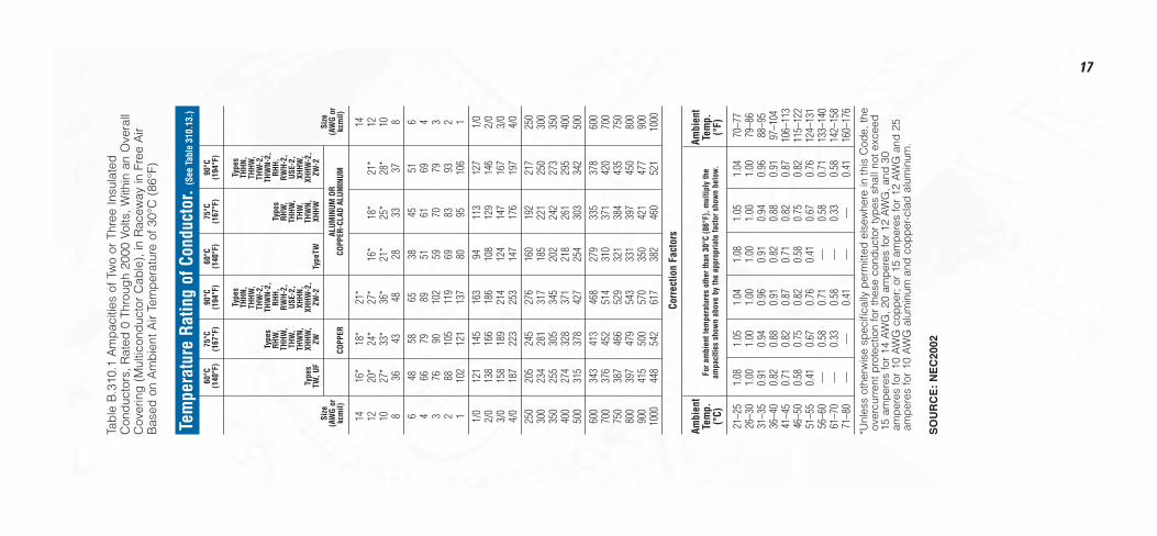
17
Tab
le B
.310
.1 A
mp
aciti
es o
f Tw
o or
Thr
ee In
sula
ted
Con
duc
tors
, Rat
ed 0
Thr
oug
h 20
00 V
olts
, With
in a
n O
vera
llC
over
ing
(M
ultic
ond
ucto
r C
able
), in
Rac
eway
in F
ree
Air
Bas
ed o
n A
mb
ient
Air
Tem
per
atur
e of
30°
C (
86°F
)
Tem
pera
ture
Rat
ing
of C
ondu
ctor
. (Se
e Ta
ble
310.
13.)
60°C
75°C
90°C
60°C
75°C
90°C
(140
°F)
(167
°F)
(194
°F)
(140
°F)
(167
°F)
(194
°F)
Type
sTy
pes
THHN
,TH
HN,
THHW
,TH
HW,
THW
-2,
THW
-2,
Type
sTH
WN-
2,TH
WN-
2,RH
W,
RHH,
Type
sRH
H,TH
HW,
RWH-
2,RH
W,
RWH-
2,TH
W,
USE-
2,TH
HW,
USE-
2,TH
WN,
XHHN
,TH
W,
XHHW
,Ty
pes
XHHW
,XH
HW-2
,TH
WN,
XHHW
-2,
TW, U
FZW
ZW-2
Type
TWXH
HWZW
-2Si
zeSi
ze(A
WG
orAL
UMIN
UM O
R(A
WG
orkc
mil)
COPP
ERCO
PPER
-CLA
D AL
UMIN
UMkc
mil)
1416
*18
*21
*14
12
20*
24*
27*
16*
18*
21*
1210
27*
33*
36*
21*
25*
28*
108
3643
4828
3337
86
4858
6538
4551
64
6679
8951
6169
43
7690
102
5970
793
288
105
119
6983
932
110
212
113
780
9510
61
1/0
121
145
163
9411
312
71/
02/
013
816
618
610
812
914
62/
03/
015
818
921
412
414
716
73/
04/
018
722
325
314
717
619
74/
025
020
524
527
616
019
221
725
030
023
428
131
718
522
125
030
035
025
530
534
520
224
227
335
040
027
432
837
121
826
129
540
050
031
537
842
725
430
334
250
060
034
341
346
827
933
537
860
070
037
645
251
431
037
142
070
075
038
746
652
932
138
443
575
080
039
747
954
333
139
745
080
090
041
550
057
035
042
147
790
010
0044
854
261
738
246
052
110
00
Corr
ectio
n Fa
ctor
s
Ambi
ent
Ambi
ent
Tem
p.Te
mp.
(°C)
(°F)
21–2
51.
081.
051.
041.
081.
051.
0470
–77
26–3
01.
001.
001.
001.
001.
001.
0079
–86
31–3
50.
910.
940.
960.
910.
940.
9688
–95
36–4
00.
820.
880.
910.
820.
880.
9197
–104
41–4
50.
710.
820.
870.
710.
820.
8710
6–11
346
–50
0.58
0.75
0.82
0.58
0.75
0.82
115–
122
51–5
50.
410.
670.
760.
410.
670.
7612
4–13
156
–60
—0.
580.
71—
0.58
0.71
133–
140
61–7
0—
0.33
0.58
—0.
330.
5814
2–15
871
–80
——
0.41
——
0.41
160–
176
*Unl
ess
othe
rwis
e sp
ecifi
cally
per
mitt
ed e
lsew
here
in th
is C
ode,
the
over
curr
ent p
rote
ctio
n fo
r th
ese
cond
ucto
r ty
pes
sha
ll no
t exc
eed
15 a
mp
eres
for
14 A
WG
, 20
amp
eres
for
12 A
WG
, and
30
amp
eres
for
10 A
WG
cop
per
; or
15 a
mp
eres
for
12 A
WG
and
25
amp
eres
for
10 A
WG
alu
min
um a
nd c
opp
er-c
lad
alu
min
um.
SO
UR
CE
: N
EC
2002
For a
mbi
ent t
empe
ratu
res
othe
r tha
n 30
°C (8
6°F)
, mul
tiply
the
ampa
citie
s sh
own
abov
e by
the
appr
opria
te fa
ctor
sho
wn
belo
w.
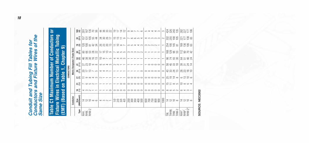
18
Co
nd
uit
an
d T
ub
ing
Fill
Tab
les
for
Co
nd
uct
ors
an
d F
ixtu
re W
ires
of
the
Sam
e S
ize
Tabl
e C1
Max
imum
Num
ber o
f Con
duct
ors
orFi
xtur
e W
ires
in E
lect
rical
Met
allic
Tub
ing
(EM
T) (B
ased
on
Tabl
e 1,
Cha
pter
9)
COND
UCTO
RS
Cond
ucto
rM
etric
Des
igna
tor (
Trad
e Si
ze)
Size
1621
2735
4153
6378
9110
3Ty
pe(A
WG/
kcm
il)(d
)(f
)(1
)(1
b)
(1d
)(2
)(2
d)
(3)
(3d
)(4
)
RHH,
144
711
2027
4680
120
157
201
RHW
,12
36
917
2338
6610
013
116
7RH
W-2
102
58
1318
3053
8110
513
58
12
47
916
2842
5570
61
13
58
1322
3444
564
11
24
610
1726
3444
31
11
45
915
2330
382
11
13
47
1320
2633
10
11
13
59
1317
221/
00
11
12
47
1115
192/
00
11
12
46
1013
173/
00
01
11
35
811
144/
00
01
11
35
79
1225
00
00
11
13
57
930
00
00
11
13
56
835
00
00
11
13
46
740
00
00
11
12
45
750
00
00
01
12
34
660
00
00
01
11
34
570
00
00
00
11
23
475
00
00
00
11
23
480
00
00
00
11
23
490
00
00
00
11
13
310
000
00
00
11
12
3TW
,14
815
2543
5896
168
254
332
424
THHW
,12
611
1933
4574
129
195
255
326
THW
,10
58
1424
3355
9614
519
024
3TH
W-2
82
58
1318
3053
8110
513
5RH
H*,
146
106
2839
6411
216
922
128
2RH
W*,
124
813
2331
5190
136
177
227
RHW
-2*,
103
610
1824
4070
106
138
177
81
46
1014
2442
6383
106
SO
UR
CE
: N
EC
2002
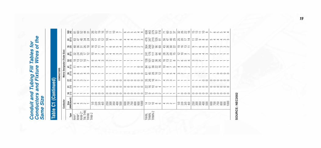
19
Co
nd
uit
an
d T
ub
ing
Fill
Tab
les
for
Co
nd
uct
ors
an
d F
ixtu
re W
ires
of
the
Sam
e S
ize
Tabl
e C1
(Con
tinue
d) COND
UCTO
RS
Cond
ucto
rM
etric
Des
igna
tor (
Trad
e Si
ze)
Size
1621
2735
4153
6378
9110
3Ty
pe(A
WG/
kcm
il)(d
)(f
)(1
)(1
b)
(1d
)(2
)(2
d)
(3)
(3d
)(4
)
RHH*
,6
13
48
1118
3248
6381
RHW
*,4
11
36
813
2436
4760
RHW
-2*,
31
13
57
1220
3140
52TW
, THW
,2
11
24
610
1726
3444
THHW
,1
11
13
47
1218
2431
THW
-21/
00
11
23
610
1620
262/
00
11
13
59
1317
223/
00
11
12
47
1115
194/
00
01
11
36
912
1625
00
01
11
35
710
1330
00
01
11
24
68
1135
00
00
11
14
67
1040
00
00
11
13
57
950
00
00
11
13
46
760
00
00
11
12
34
670
00
00
01
11
34
575
00
00
01
11
34
580
00
00
01
11
33
590
00
00
00
11
23
410
000
00
00
11
23
4TH
HN,
1412
2235
6184
138
241
364
476
608
THW
N,12
916
2645
6110
117
626
634
744
3TH
WN-
210
510
1628
3863
111
167
219
279
83
69
1622
3664
9612
616
16
24
712
1626
4669
9111
64
12
47
1016
2843
5671
31
13
68
1324
3647
602
11
35
711
2030
4051
11
11
45
815
2229
371/
01
11
34
712
1925
322/
00
11
23
610
1620
263/
00
11
13
58
1317
224/
00
11
12
47
1114
1825
00
01
11
36
911
1530
00
01
11
35
710
1335
00
01
11
24
69
1140
00
00
11
14
68
1050
00
00
11
13
56
860
00
00
11
12
45
770
00
00
11
12
34
675
00
00
01
11
34
580
00
00
01
11
34
590
00
00
01
11
33
410
000
00
01
11
23
4
SO
UR
CE
: N
EC
2002

20
Tabl
e C4
Max
imum
Num
ber o
f Con
duct
ors
orFi
xtur
e W
ires
in In
term
edia
te M
etal
Con
duit
(IMC)
(Bas
ed o
n Ta
ble
1, C
hapt
er 9
)CO
NDUC
TORS
Cond
ucto
rM
etric
Des
igna
tor (
Trad
e Si
ze)
Size
1621
2735
4153
6378
9110
3Ty
pe(A
WG/
kcm
il)(d
)(f
)(1
)(1
b)
(1d
)(2
)(2
d)
(3)
(3d
)(4
)
RHH,
144
813
2230
4970
108
144
186
RHW
,RH
W-2
124
611
1825
4158
8912
015
4RH
H,10
35
815
2033
4772
9712
4RH
W,
81
34
810
1724
3850
65RH
W-2
61
13
68
1419
3040
524
11
35
611
1523
3141
31
12
46
913
2128
362
11
13
58
1118
2431
10
11
23
57
1216
201/
00
11
13
46
1014
182/
00
11
12
46
912
153/
00
01
11
35
710
134/
00
01
11
34
69
1125
00
01
11
13
56
830
00
00
11
13
46
735
00
00
11
12
45
740
00
00
11
12
35
650
00
00
11
11
34
560
00
00
01
11
23
470
00
00
01
11
23
475
00
00
01
11
13
480
00
00
00
11
13
390
00
00
00
11
12
310
000
00
00
11
12
312
500
00
00
11
11
215
000
00
00
01
11
117
500
00
00
01
11
120
000
00
00
01
11
1TW
,14
1017
2747
6410
414
722
830
439
2TH
HW,
127
1321
3649
8011
317
523
430
1TH
W,
105
915
2736
5984
130
174
224
THW
-28
35
815
2033
4772
9712
4RH
H*,
146
1118
3142
6998
151
202
261
RHW
*,RH
W-2
RHH*
,12
59
1425
3456
7912
216
320
9RH
W*,
RHW
-2*
104
711
1926
4361
9512
716
3RH
H*,
82
47
1216
2637
5776
98RH
W*,
RHW
-2*
RHH*
,6
13
59
1220
2843
5875
RHW
*,RH
W-2
*,4
12
46
915
2132
4356
SO
UR
CE
: N
EC
2002
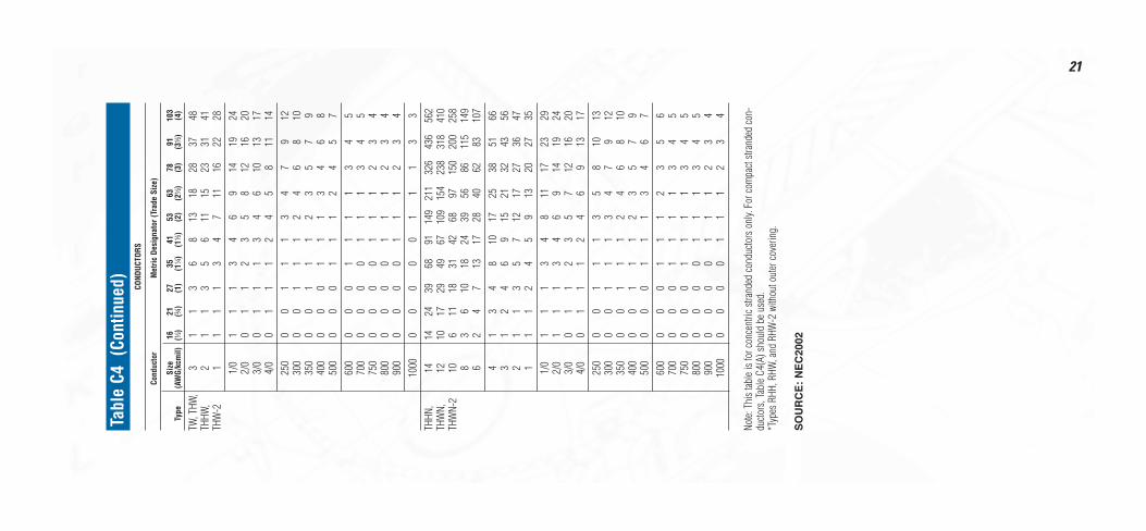
21
Tabl
e C4
(Co
ntin
ued) CO
NDUC
TORS
Cond
ucto
rM
etric
Des
igna
tor (
Trad
e Si
ze)
Size
1621
2735
4153
6378
9110
3Ty
pe(A
WG/
kcm
il)(d
)(f
)(1
)(1
b)
(1d
)(2
)(2
d)
(3)
(3d
)(4
)
TW, T
HW,
31
13
68
1318
2837
48TH
HW,
21
13
56
1115
2331
41TH
W-2
11
11
34
711
1622
281/
01
11
34
69
1419
242/
00
11
23
58
1216
203/
00
11
13
46
1013
174/
00
11
12
45
811
1425
00
01
11
34
79
1230
00
01
11
24
68
1035
00
01
11
23
57
940
00
00
11
13
46
850
00
00
11
12
45
760
00
00
11
11
34
570
00
00
01
11
34
575
00
00
01
11
23
480
00
00
01
11
23
490
00
00
01
11
23
410
000
00
00
11
13
3TH
HN,
1414
2439
6891
149
211
326
436
562
THW
N,12
1017
2949
6710
915
423
831
841
0TH
WN-
210
611
1831
4268
9715
020
025
88
36
1018
2439
5686
115
149
62
47
1317
2840
6283
107
41
34
810
1725
3851
663
12
46
915
2132
4356
21
13
57
1217
2736
471
11
24
59
1320
2735
1/0
11
13
48
1117
2329
2/0
11
13
46
914
1924
3/0
01
12
35
712
1620
4/0
01
11
24
69
1317
250
00
11
13
58
1013
300
00
11
13
47
912
350
00
11
12
46
810
400
00
11
12
35
79
500
00
01
11
34
67
600
00
01
11
23
56
700
00
01
11
13
45
750
00
01
11
13
45
800
00
00
11
13
45
900
00
00
11
12
34
1000
00
00
11
12
34
Note:
Thi
s tab
le is
for c
once
ntric
stra
nded
con
ducto
rs o
nly.
For c
ompa
ct str
ande
d co
n-du
ctors
, Tab
le C4
(A) s
houl
d be
use
d.*T
ypes
RHH
, RHW
, and
RHW
-2 w
ithou
t out
er c
over
ing.
SO
UR
CE
: N
EC
2002
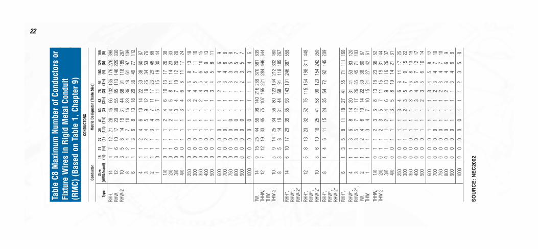
22
Tabl
e C8
Max
imum
Num
ber o
f Con
duct
ors
orFi
xtur
e W
ires
in R
igid
Met
al C
ondu
it(R
MC)
(Bas
ed o
n Ta
ble
1, C
hapt
er 9
)CO
NDUC
TORS
Cond
ucto
rM
etric
Des
igna
tor (
Trad
e Si
ze)
Size
1621
2735
4153
6378
9110
312
915
5Ty
pe(A
WG/
kcm
il)(d
)(f
)(1
)(1
b)
(1d
)(2
)(2
d)
(3)
(3d
)(4
)(5
)(6
)
RHH,
144
712
2128
4666
102
136
176
276
398
RHW
,12
36
1017
2338
5585
113
146
229
330
RHW
-210
35
814
1931
4468
9111
818
526
78
12
47
1016
2336
4861
9713
96
11
36
813
1829
3849
7711
24
11
24
610
1422
3038
6087
31
12
45
912
1926
3453
762
11
13
47
1117
2329
4666
10
11
13
57
1115
1930
441/
00
11
12
46
1013
1726
382/
00
11
12
45
811
1423
333/
00
01
11
34
710
1220
284/
00
01
11
34
68
1117
2425
00
00
11
13
46
813
1830
00
00
11
12
45
711
1635
00
00
11
12
45
610
1540
00
00
11
11
34
69
1350
00
00
11
11
34
58
1160
00
00
01
11
23
46
970
00
00
01
11
13
46
875
00
00
00
11
13
35
880
00
00
00
11
12
35
790
00
00
00
11
12
35
710
000
00
00
11
11
34
6TW
,14
915
2544
5998
140
216
288
370
581
839
THHW
,12
712
1933
4575
107
165
221
284
446
644
THW
,TH
W-2
105
914
2534
5680
123
164
212
332
480
83
58
1419
3144
6891
118
185
267
RHH*
,14
610
1729
3965
9314
319
124
638
755
8RH
W*,
RHW
-2*
RHH*
,12
58
1323
3252
7511
515
419
831
144
8RH
W*,
RHW
-2*
103
610
1825
4158
9012
015
424
235
0RH
H*,
81
46
1115
2435
5472
9214
520
9RH
W*,
RHW
-2*
RHH*
,6
13
58
1118
2741
5571
111
160
RHW
*,4
11
36
814
2031
4153
8312
0RH
W-2
*,3
11
35
712
1726
3545
7110
3TW
,2
11
24
610
1422
3038
6087
THW
,1
11
13
47
1015
2127
4261
THHW
,1/
00
11
23
68
1318
2336
52TH
W-2
2/0
01
12
35
711
1519
3144
3/0
01
11
24
69
1316
2637
4/0
00
11
13
58
1014
2131
250
00
11
13
46
811
1725
300
00
11
12
35
79
1522
350
00
01
11
35
68
1319
400
00
01
11
34
67
1217
500
00
01
11
23
56
1014
600
00
01
11
13
45
812
700
00
00
11
12
34
710
750
00
00
11
12
34
710
800
00
00
11
12
34
69
900
00
00
11
11
34
68
1000
00
00
01
11
23
58
SO
UR
CE
: N
EC
2002

23
Tabl
e C8
(Con
tinue
d) COND
UCTO
RS
Cond
ucto
rM
etric
Des
igna
tor (
Trad
e Si
ze)
Size
1621
2735
4153
6378
9110
312
915
5Ty
pe(A
WG/
kcm
il)(d
)(f
)(1
)(1
b)
(1d
)(2
)(2
d)
(3)
(3d
)(4
)(5
)(6
)
THHN
,14
1322
3663
8514
020
030
941
253
183
312
02TH
WN,
129
1626
4662
102
146
225
301
387
608
877
THW
N-2
106
1017
2939
6492
142
189
244
383
552
83
69
1622
3753
8210
914
022
131
86
24
712
1627
3859
7910
115
923
04
12
47
1016
2336
4862
9814
13
11
36
814
2031
4153
8312
02
11
35
711
1726
3444
7010
01
11
14
58
1219
2533
5174
1/0
11
13
47
1016
2127
4363
2/0
01
12
36
813
1823
3652
3/0
01
11
35
711
1519
3043
4/0
01
11
24
69
1216
2536
250
00
11
13
57
1013
2029
300
00
11
13
46
811
1725
350
00
11
12
35
710
1522
400
00
11
12
35
78
1320
500
00
01
11
24
57
1116
600
00
01
11
13
46
913
700
00
01
11
13
45
811
750
00
00
11
13
45
711
800
00
00
11
12
34
710
900
00
00
11
12
34
69
1000
00
00
11
11
34
68
Note:
Thi
s tab
le is
for c
once
ntric
stra
nded
con
ducto
rs o
nly.
For c
ompa
ct str
ande
d co
n-du
ctors
, Tab
le C8
(A) s
houl
d be
use
d.*T
ypes
RHH
, RHW
, and
RHW
-2 w
ithou
t out
er c
over
ing.
SO
UR
CE
: N
EC
2002
Met
ric C
ondu
ctor
sW
ire S
ize
# of
Stra
ndDi
amet
erDi
amet
erCo
lor
Die
MM
AWG
Circ
Mils
Stra
nds
Diam
eter
MM
Inch
Code
Code
108
19,7
301
3.57
3.57
0.14
0Re
d21
108
19,7
307
1.35
4.05
0.15
9Re
d21
166
31,5
581
4.50
4.50
0.17
7Bl
ue24
166
31,5
587
1.70
5.10
0.20
0Bl
ue24
252
49,3
257
2.14
6.42
0.25
3Gr
ay29
252
49,3
2519
1.35
6.75
0.26
6Br
own
3335
169
,055
191.
537.
650.
300
Gree
n37
501/
098
,650
191.
788.
900.
350
Pink
4270
2/0
138,
110
192.
1410
.70
0.42
1Bl
ack
4595
3/0
187,
500
192.
5212
.60
0.49
6Or
ange
5095
3/0
187,
500
371.
7812
.46
0.49
0Or
ange
5012
025
023
6,76
037
2.03
14.2
10.
560
Purp
le54
150
300
295,
950
372.
2515
.75
0.62
0W
hite
6618
536
5,00
061
2.52
17.6
40.
695
Red
7124
050
047
3,50
061
2.25
20.2
50.
797
Brow
n87
300
591,
900
612.
5222
.68
0.89
3Gr
een
9440
078
9,20
061
2.85
25.6
51.
000
Blac
k10
640
078
9,20
091
2.36
25.9
61.
022
Blac
k10
650
098
6,50
061
3.20
28.8
01.
134
125
500
986,
500
912.
6529
.15
1.14
863
01,
243,
000
127
2.52
32.7
61.
290
800
1,57
8,40
012
72.
8537
.05
1.45
910
001,
973,
000
127
3.20
41.6
01.
638

The Complete Connector and Tool System
Color-Keyed ®Offers a Complete Line of Manual and Powered Compression Tools. Thomas & Betts – Your Source for Highest Qualityin Industrial Electrical Components.Color-Keyed products offer the best quality and value for compressionconnections. T&B also brings an entire package of quality groundingproducts for a complete solutions system, including Blackburn ®
Mechanical, Compression Connectors, Grounding Products andFurseweld ® Exothermic Grounding System.For other industrial applications, be sure to specify the brands youknow and trust:• Ty-Rap ® Specification-grade cable ties• Taylor ® non-metallic wiring duct• Sta-Kon ® Terminals and tools.• Dragon Tooth ® Insulation-piercing connectors• E-Z-Code® Identification products.• Shrink-Kon ® Insulation products.• T&B Conduit Fittings for EMT, rigid, armored flex, jacketed metal
clad cable, liquidtight, portable cord and Romex cable.• Ocal ® Corrosion Protection• Russellstoll ® Interconnection systems.• Hazlux ® hazardous location lighting systems
TBM62BSCRSingle-handed battery-powered compressiontool, features rotatinghead and comfortablebalance. For connec-tors up to 500MCMCU, 350MCM AL.
TBM14BSCRCompact, portable 14-ton self-containedcompression tool, forlug and splices up to900MCM CU,750MCM AL.
TBM15BSCRHigh-grade forged steelhead, portable designfor 15-ton compres-sion. For connectorsup to 1500MCM CU,1000MCM AL.
TBM15I15-ton insulatedhydraulic tool, slimprofile, operates from10,000PSI pumps.Ranges to 1500MCMCU, 1000 MCM AL.
Pumpac® IIThe newest battery-powered hydraulicpump, rated for 10,000PSI. Portable power forall T&B hydraulic heads,using just two 14.4rechargeable batteries.
TBM6BSCRRugged, reliable 6ton compressiontool featuring openjaw design, #8-600MCM CU, #8-350MCM AL.
TBM25SErgonomic manualtool with rotatingdie head. Installslugs and splices upto #2 CU and #6 AL
© 2002 Thomas & Betts Corporation. All rights reserved. Printed in U.S.A. 1/02/30M Order No. GM-2100Thomas & Betts Corporation • Electrical Division • 8155 T&B Boulevard • Memphis, Tennessee 38125 Thomas & Betts Ltd. • 700 Thomas Avenue • Iberville, Québec J2X 2M9
For tool service and repair, call 1-800-284-TOOL (8665).