
COMPRESSED AIR PIPING SYSTEM - topring.com · TOPRING 5 96.615_installation_guide_February_26_2018...
28
TOPRING_SicoAIR_March_16_2018 COMPRESSED AIR PIPING SYSTEM
Transcript of COMPRESSED AIR PIPING SYSTEM - topring.com · TOPRING 5 96.615_installation_guide_February_26_2018...

TOPRING_SicoAIR_March_16_2018
COMPRESSED AIR PIPING SYSTEM

2 TOPRING
Unlike the usual methods of threading or welding required by conventional steel systems, the SicoAIR compressed air piping system from Series 06 is assembled compression fittings to effectively reduce production downtime during installation and labor costs. For more details on benefits and features or to view the installation video, visit TOPRING.com.
TOPRINGCOMPRESSED AIR PIPING SYSTEM
See video on TOPRING.com

TOPRING 3
Certifications and technical specifications .................4Warranty ...................................................5Features and benefits .....................................6
Guide to determine the minimum diameter pipe sizing for a compressed air network .............................7Product features ........................................ 8-9 • Rigid aluminium pipes ....................................................8 • Fittings ...........................................................................9
Product descriptions ..................................10-18 • Pipes ...........................................................................10 • Flexible hoses ...............................................................11 • Unions .........................................................................12 • Twin take-off drop couplings ...........................................13 • Water traps “T” ..............................................................14 • Threaded drops connections ..........................................14 • Tees and reducers .........................................................15 • Threaded connections ....................................................16 • Valves and drains ..........................................................17 • Adapters .......................................................................18
Manifolds .............................................19-22 • Composite manifolds ................................................. 19-21 • Aluminium manifolds ......................................................22
Mounting clips for rigid pipes ............................ 23
Installation tools and practical tools ..................... 24
Mounting accessories ................................... 25
TABLE OF CONTENTS

TÜV Certification• A product certified TÜV is a
pledge of safety and quality.
• The group TÜV thus certifies independent test results - in particular, the properties of the products and the standards whereby they were examined.
ASME B31.3• Meets the requirement of ASME B31.3
This code prescribes requirements for material and components, design, fabrication, assembly, erection, examination, inspection, and testing of piping.
Canadian Registration Number• SicoAIR products have an
CRN for all of Canada.
QUALICOAT Certification• QUALICOAT certification is a
guarantee of the quality of the lacquer finish applied to aluminium pipes.
ISO 9001: 2008• Manufactured under ISO quality management system.
4 TOPRING 4 TOPRING
CERTIFICATIONS
CRNCANDIAN REGISTRATION NUMBER
SPECIFICATIONSFluids• Compressed air (dry, wet, lubricated)
• Nitrogen (TOPRING SicoAZOTE)
Maximum Working Pressure• Pipes: 217 PSI (15 BAR)• Fittings: 181 PSI (12.5 BAR)
Normal Working Pressure• 181 PSI (12.5 BAR)
Vacuum Level• 80% (29.6 "Hg)
Working Temperature• -20 °C to 70 °C
Resistance to• Corrosion• Aggressive environments• Thermal variations• UV• Mineral and synthetic oils for compressor
Environment• Materials used to produce the pipes and fittings
are 100% recyclable
• All pipes and fittings are guaranteed silicone-free

TOPRING 5TOPRING 5
96.615_installation_guide_February_26_2018
DESIGN AND INSTALLATION GUIDE
Series 06 Compressed air piping system
TOPRINGCompressed air solutions
DESIGN AND INSTALLATION GUIDEIt is recommended that you carefully read the “Design and Installation Guide” of the TOPRING SicoAIR Series 06 as it provides important information for system configuration, installation, operation, maintenance and responsibility of the buyer and / or user and that of TOPRING.
Guide available on TOPRING.com
10YEARWARRANTY
EAREAREAREAREARARARARARARARARARARARARARAR
TOPRING
TOPRING does not warrant the design, assembly or installation of the system, but only the SicoAIR components as stated herein. TOPRING is not responsible for improper design, assembly or installation, or for any modifications of the SicoAIR products.
The warranty herein is void upon:1. Failure to follow any of the assembly or installation guidelines.2. Installation, repair or relocation of the components by a person other than a trained
and qualified installer.3. Alteration, misuse or abuse of, or damage to, any other the SicoAIR products.4. Operation beyond the design range, excessive pressure or stress, or mishandling
in any way.5. Improper assembly, installation, service or maintenance.
WARRANTYTOPRING warrants its SicoAIR products to be free of defects in material and workmanship for a period of ten (10) years from the date of purchase of the products. TOPRING makes no other warranties, express or implied. This limitation explicitly excludes any implied warranty of merchantability of fitness for a particular purpose. The sole remedy for breach of this warranty of material and workmanship or for negligence in manufacture of design is limited to replacement or repair, at the sole option of TOPRING, of any defective parts which are returned to TOPRING (prepaid) within ten (10) years of original purchase. In no event shall TOPRING be liable for indirect, special, incidental or consequential damages of any kind. No allowance will be made for repairs made by the purchaser.
THIS WARRANTY IS EXPRESSLY IN LIEU OF ANY AND ALL OTHER WARRANTIES AND REPRESENTATIONS, EXPRESS OR IMPLIED, INCLUDING BUT NOT LIMITED TO, THE WARRANTY OF FITNESS FOR A PARTICULAR PURPOSE AND THE WARRANTY
OF MERCHANTABILITY. TOPRING MAKES NO WARRANTY THAT THE GOODS SOLD HEREUNDER ARE
DELIVERED FREE OF THE RIGHTFUL CLAIM OF ANY THIRD PARTY BY WAY OF INFRINGEMENT OR OTHERWISE. THERE ARE NO WARRANTIES THAT EXTEND BEYOND THE DESCRIPTION ON THE FACE HEREOF THE EXCLUSIVE REMEDY FOR DEFECTIVE PRODUCTS SHALL BE ONLY AS STATED HEREIN.

6 TOPRING 6 TOPRING
FEATURES AND BENEFITS
• The installation is 50% to 75% faster than a conventional steel system, thanks to the screwed connections (no welding, soldering and threading of heavy components)
• SicoAIR pipes and fittings can be assembled by a single installer
• SicoAIR pipes and fittings are lighter than conventional steel or black iron system
• The twin take-off drop fittings make it possible to install air drops on the main line simply and quickly, even if the system is pressurized
Easy to install
• Aluminum pipes ensure the absence of corrosion (which is not the case for conventional steel or galvanized steel systems)
• Aluminum pipes, combined with adequate air treatment, prolong the service life of the equipement and of the filters
• With the total absence of corrosion in the aluminum pipes, the air turbulence is eliminated, allowing a constant air flow and reduced pressure drops
Clean air and optimum efficiency
• Saves energy: Calibrated aluminum pipes assembled with compression fittings eliminate air leakage, reducing energy costs by up to 10%. They also allow high air flow rates and low pressure drops because the smooth interior of the pipes and fittings reduces friction losses
• Substantial reduction in installation costs which often include more labor costs than materials
• Reduces production downtime when installing or adding components
• Reduces maintenance costs
Economical
• The SicoAIR system is easily removable and reusable: it can be reinstalled elsewhere without damaging its components
Easy to modify or extend
See the video on TOPRING.com « SicoAIR vs. steel pipe installation »

TOPRING 7TOPRING 7
100' 150' 200' 250' 300' 400' 500' 600' 700' 800' 900' 1000' 1250' 1500' 2000'5 20 20 20 20 20 20 20 20 20 20 20 20 20 20 20
10 20 20 20 20 20 20 20 20 20 20 20 20 20 20 2015 20 20 20 20 20 20 20 20 20 20 20 20 20 20 2020 20 20 20 20 20 20 20 20 20 20 20 20 20 20 2530 20 20 20 20 20 20 20 20 20 20 25 25 25 25 2540 20 20 20 20 20 20 25 25 25 25 25 25 25 25 3260 20 20 20 25 25 25 25 25 25 25 32 32 32 32 3280 20 25 25 25 25 25 32 32 32 32 32 32 32 32 32
100 25 25 25 25 25 32 32 32 32 32 32 32 32 40 40125 25 25 32 32 32 32 32 32 32 32 40 40 40 40 40150 25 32 32 32 32 32 32 40 40 40 40 40 40 40 40200 32 32 32 32 32 40 40 40 40 40 40 40 50 50 50300 32 40 40 40 40 40 40 50 50 50 50 50 50 50 63400 40 40 40 40 40 50 50 50 50 50 50 63 63 63 63500 40 40 50 50 50 50 50 50 63 63 63 63 63 63 63750 50 50 50 50 63 63 63 63 63 63 63 63
1000 50 50 63 63 63 63 631500 63 63 63 63
25' 50' 75' 100' 150' 200' 250' 300' 400' 500' 600' 700' 800' 900' 1000'5 20 20 20 20 20 20 20 20 20 20 20 20 20 20 20
10 20 20 20 20 20 20 20 20 20 20 20 20 20 20 2515 20 20 20 20 20 20 20 20 20 25 25 25 25 25 2520 20 20 20 20 20 20 25 25 25 25 25 25 25 25 3230 20 20 20 20 25 25 25 25 25 32 32 32 32 32 3240 20 20 25 25 25 25 32 32 32 32 32 32 32 32 3260 20 25 25 25 32 32 32 32 32 40 40 40 40 40 4080 25 25 32 32 32 32 32 40 40 40 40 40 40 40 50
100 25 32 32 32 32 40 40 40 40 40 40 50 50 50 50125 32 32 32 32 40 40 40 40 50 50 50 50 50 50 50150 32 32 40 40 40 40 40 50 50 50 50 50 50 63 63200 32 40 40 40 40 50 50 50 50 63 63 63 63 63 63300 40 40 50 50 50 50 63 63 63 63 63 63 63400 40 50 50 50 63 63 63 63 63500 50 50 50 63 63 63 63750 50 63 63 631000 63 631500 63
SCFM FEET
Minimum diameter pipe sizing for a closed loop network
GUIDE TO DETERMINE THE MINIMUM DIAMETER PIPE SIZING FOR A COMPRESSED AIR NETWORK1. Identify the type of network: closed loop or dead-end
2. Calculate the total length of the line (feet)
3. Determine the total flow required (SCFM)
4. Use the charts below in order to identify the proper diameter size
• Calculations based on total maximum pressure drop ( P) of no more than 3 PSIG for the entire network, at 100 PSIG at 15.5 °C• Total flow required takes account of all flows for all compressed air powered tools and equipment• Note that a typical compressor will produce approximately 4 SCFM per HP
WARNINGInstallation of TOPRING SicoAIR compressed air piping system must be made according to the assembly instructions as indicated in the installation guide. Carefully read the installation guide prior proceeding.
TOTAL LENGTH OF THE NETWORK (FEET)
TOTAL LENGTH OF THE NETWORK (FEET)
TOTA
L FL
OW R
EQUI
RED
TOTA
L FL
OW R
EQUI
RED
Minimum diameter pipe sizing for a dead end network
SCFM FEET

8 TOPRING 8 TOPRING
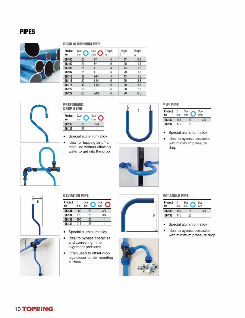
RIGID ALUMINIUM PIPES
25 mm
32 mm
40 mm
50 mm
63 mm
20 mm20 mm
SPECIFICATIONS
• Materials:
Aluminium extrusion alloy EN AW-6060 T6 with inside and outside titanium-based, chrome-free and RoHS-complying treating and electrocoated outside surface
• Color: Blue RAL 5015
• Manufacturing process: Seamless extrusion process
• Marking:
• Available in 6 sizes: 20, 25, 32, 40, 50 and 63 mm• Tubular extruded aluminium pipes• Calibrated aluminium pipes for perfect and leak-free assembly with fittings• Lightweight• Smooth, clean and corrosion resistant• Fast and easy installation• Can be installed on an existing compressed air system with NPT adapters• QUALICOAT certified powder-coated blue paint for compressed air identification• Suitable for compressed air, vacuum and nitrogen
Traditional pipes corrode and allow contaminant build-up
TOPRING pipes resist corrosion andstay clean over time
Outside diameter
mmProduction Date
week/yearLot
NumberMaterial

TOPRING 9TOPRING 9
Nitrogen piping system • Series 06 TOPRING
1
2
3
4
55
2
4
1
3
TOPRING offers green pipes and fittings to help identify a network with nitrogen.See the TOPRING catalogUE pages 110 to 117 for more information on TOPRING SicoAzote products available.
STRONG INTERNAL GRIP DESIGN Stainless steel clinch ring increasing grip, strength and safety
DISTINCTIVE NUT DESIGN The grooves on the nut allow you to use the spanner wrench for safe tightening without damaging the nut
EXCLUSIVE BODY DESIGN Inner body design and large diameter minimizes the flow resistance and pressure drop
PRECISE ALIGNMENT GUIDE Nut design allows pipe insertion with perfect alignment
PARTS IDENTIFICATION
• TOPRING SicoAIR reference • Diameter engraved for easy identification of size • Nominal pressure
TOPRING SicoAIR fitting design
FITTINGS• Quick installation: quick and easy assembly of the pipes, thanks to the compression fittings
• Polyamide compression fittings
• High resistance to corrosion, mechanical shocks and thermal variations
• Smooth internal finish
• Quick branch drop leg fitting can be installed anywhere in the piping network
10 TOPRING 10 TOPRING
D
D
D
Product No
D mm
Size mm
Size inch
06.133 140 20 3/406.138 145 25 1
PREFORMED DROP BEND
RIGID ALUMINIUM PIPE
DEVIATION PIPE
Product No
Size mm
Size inch
06.130 20 3/406.135 25 1
• Special aluminium alloy
• Ideal to bypass obstacles and correcting minor alignment problems
• Often used to offset drop legs closer to the mounting surface
• Special aluminium alloy
• Ideal to bypass obstacles with minimum pressure drop
• Special aluminium alloy
• Ideal for tapping air off a main line without allowing water to get into the drop
• Special aluminium alloy
• Ideal to bypass obstacles with minimum pressure drop
" U " PIPE
90O ANGLE PIPE
Product No
D mm
Size mm
Size inch
06.132 145 20 3/406.137 175 25 1
PIPES
Product No
D mm
Size mm
Size inch
06.131 80 20 3/406.134 175 20 3/406.136 100 25 106.139 215 25 1
Product No
Size mm
Size inch
Length m
Length ft
Weight kg
06.100 20 3/4 4 13 0.906.102 20 3/4 6 20 1.406.105 25 1 4 13 1.206.107 25 1 6 20 1.806.110 32 1-1/4 4 13 1.506.112 32 1-1/4 6 20 2.306.117 40 1-1/2 6 20 3.106.122 50 2 6 20 5.106.127 63 2-1/2 6 20 6.5

TOPRING 11TOPRING 11
R
MaterialsHose and Braid: Stainless steel
Fitting: Steel (Stainless steel available upon request)
FLEXIBLE RUBBER ANTI-VIBRATION HOSE
FEMALE UNION (3 PIECES)
Length 24 in Length 48 in Fittings (M) NPT
Hose I.D. in
Minimum Bend Radius inProduct No Product No
09.200 09.220 1/2 1/2 709.202 09.222 3/4 3/4 9-1/209.204 09.224 1 1 1209.206 09.226 1-1/4 1-1/4 16-1/209.208 09.228 1-1/2 1-1/2 19-11/1609.210 09.230 2 2 25
FLEXIBLE HOSES
Typical installation
Typical installation
• Corrugated flexible stainless steel hose is designed to minimize vibration and heat coming from the compressor
• Protects downstream airline system from vibration shocks
• Meets ISO 10380 specifications
Features and benefits
MaterialsCover: Oil resistant synthetic rubber
Inner tube: Oil and heat-resistant rubber
Reinforcement: Single braid high tensile steel wire
SpecificationsMaximum working pressure : 500 PSI
Working temperature: -40 °C to 100 °C
• Designed for bypassing obstacles and/or overcoming misalignments of airlines
• Ideal for connecting a compressor outlet to an airline system
• Expansion loops• Adaptable to all building configurations• Corrosion-proof rubber hose, good for most
environments • Resists mineral and synthetic oils, heat and
weathering• Extends compressor and airline system life by
reducing stress from vibrations and misalignments
Features and benefits
To minimize possible torque damage to a hose, a union or floating flange, should be used at one end of the hose assembly
Product No
Thread (F) NPT
41.368 1/241.369 3/441.370 141.371 1-1/441.373 2
SpecificationsWorking temperature: -40 °C to 250 °C
Maximum working pressure : See table above
HIGH TEMPERATURE FLEXIBLE STAINLESS STEEL ANTI-VIBRATION HOSELength 12 in Length 24 in Fittings
(M) NPTMaximumMisalignment in
Maximum Working Pressure PSI at 21 ˚CProduct No Product No
09.100 09.120 1/2 1-3/4 113709.102 09.122 3/4 2-3/4 91009.104 09.124 1 3-1/2 71109.106 09.126 1-1/4 4-1/2 56809.108 09.128 1-1/2 5 42609.110 09.130 2 7-5/8 398

12 TOPRING 12 TOPRING
1
2
UNION CONNECTIONS • ELBOW UNIONS
1 2
STRAIGHT UNION 90O ELBOW UNION
Product No Size mm06.262 2006.267 2506.272 3206.275 4006.277 5006.280 63
45O ELBOW UNION
Product No Size mm06.282 2006.283 2506.284 3206.285 4006.286 5006.287 63
REDUCING UNION
Product No Size mm06.302 2006.307 2506.312 3206.315 4006.317 5006.320 63
Product No Size mm Size mm06.308 25 2006.313 32 2506.316 40 3206.318 50 40 06.321 63 50
Product No Description97.183 SicoAIR product sample case
Each sample case includes:
Twin Drop Coupling • 25 mm x 1/2(F) 06.050
Connector (M) • 32 mm x 1(M) 06.212
Connector (F) • 32 mm x 1(F) 06.242
Union Elbow • 90° / 25 mm 06.267
Union Reducer • 3 2mm x 25mm 06.313
Wall Mounting Monoklip • 25 mm 06.542
06.950 Reducer (F) • 32mm x 1/2(F) 06.950
6 different aluminium tube diameters
TOPRING 13TOPRING 13
1 2
1
2
1
2
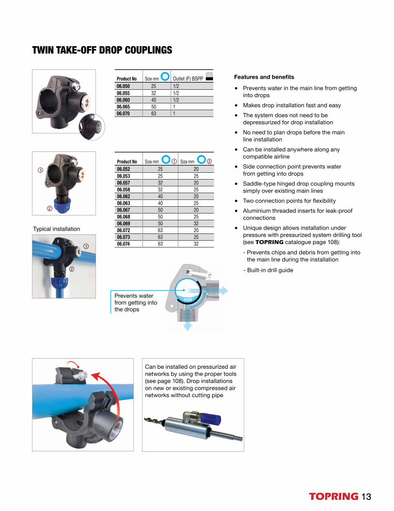
TWIN TAKE-OFF DROP COUPLINGS
Typical installation
Product No Size mm Outlet (F) BSPP06.050 25 1/206.055 32 1/206.060 40 1/206.065 50 1 06.070 63 1
Product No Size mm Size mm06.052 25 2006.053 25 2506.057 32 2006.058 32 2506.062 40 2006.063 40 2506.067 50 2006.068 50 2506.069 50 3206.072 63 2006.073 63 2506.074 63 32
Prevents water from getting intothe drops
• Prevents water in the main line from getting into drops
• Makes drop installation fast and easy
• The system does not need to be depressurized for drop installation
• No need to plan drops before the main line installation
• Can be installed anywhere along any compatible airline
• Side connection point prevents water from getting into drops
• Saddle-type hinged drop coupling mounts simply over existing main lines
• Two connection points for flexibility
• Aluminium threaded inserts for leak-proof connections
• Unique design allows installation under pressure with pressurized system drilling tool (see TOPRING catalogue page 108): - Prevents chips and debris from getting into
the main line during the installation
- Built-in drill guide
Features and benefits
Can be installed on pressurized air networks by using the proper tools (see page 108). Drop installations on new or existing compressed air networks without cutting pipe

14 TOPRING 14 TOPRING
1
1
2
1 2
THREADED DROP CONNECTIONS
Typical installation
• Makes drop installation fast and easy
• No need to plan drops before the main line installation
• Saves time during installation
• Drop connection mounts simply over existing TOPRING SicoAIR main lines
• Can be installed anywhere along a compatible airline
• Aluminium threaded inserts for leak-proof connections
For rigid drops with horizontal take off or for all types of air supply with rigid pipe on an installation which incorporates an efficient air dryerMakes drop installations on new or existing compressed air networks without cutting pipe
Applications
Features and benefits
Features and benefits
Product No Size mm Outlet (F) BSPP06.080 25 1/206.084 32 1/206.086 32 3/406.090 40 1/206.092 40 3/4
WATER TRAP TEES
Typical installation
• Makes drop installation fast and easy
• Prevents water in the main line from going into drops
• Makes drop installations on new or existing compressed compatible air networks
CONDENSATESTOP
CONDENSATE CONDENSATE
AIR
AIR
AIR
Product No Size mm Size mm06.970 40 2006.971 40 2506.972 50 2006.973 50 2506.974 50 3206.975 50 4006.976 63 2006.977 63 2506.978 63 3206.979 63 4006.980 63 50

TOPRING 15
11
2
1 2
TEES • REDUCERS
EQUAL TEE
Product No Size mm06.332 2006.337 2506.342 3206.345 40 06.347 50 06.350 63
REDUCING TEE
THREADED REDUCING TEE BSPP
Product No
Size mm
Thread (F) BSPP
06.338 25 1/206.343 32 3/406.346 40 106.348 50 1-1/2 06.351 63 2
ProductNo
Size mm
Thread (F) BSPP
06.950 32 1/206.952 40 1/206.954 40 106.956 50 1/2 06.958 50 1 06.960 63 1/2 06.962 63 1 06.964 63 1-1/2
THREADED PLUG-IN REDUCER BSPP
Specifically designed for use with the female branch Tee (BSPP) connector
THREADED REDUCER BSPPProduct No
Thread (M) BSPP
Thread (F) BSPP
06.916 3/4 1/206.918 1 1/206.920 1-1/2 1/2 06.922 1-1/2 106.924 2 1/206.926 2 106.928 2 1-1/2
Product No
Size mm
Size mm
06.385 25 2006.386 32 2006.387 32 2506.388 40 20 06.389 40 25 06.390 40 32 06.391 50 20 06.392 50 25 06.393 50 32 06.394 50 40 06.395 63 20 06.396 63 25 06.397 63 32 06.398 63 40 06.399 63 50

16 TOPRING 16 TOPRING
THREADED CONNECTIONS
END CAP
REPLACEMENT PARTS
Product No Size mm06.362 2006.367 2506.372 3206.375 40 06.377 50 06.380 63
Product No Size mm06.560 2006.561 2506.562 3206.563 40 06.564 50 06.565 63
FEMALE THREADED CONNECTOR BSPP
MALE THREADED CONNECTOR BSPT
MALE THREADED ALUMINIUM CONNECTOR NPT
FEMALE THREADED ALUMINIUM CONNECTOR NPT
Product No
Size mm
Thread (M) BSPT
06.202 20 1/206.203 20 3/406.206 25 1/206.208 25 3/406.209 25 106.212 32 1 06.213 32 1-1/406.214 40 106.215 40 1-1/4 06.216 40 1-1/206.217 50 1-1/2 06.218 50 2 06.220 63 2 06.221 63 2-1/2
Product No
Sizemm
Thread (F) BSPP
06.232 20 1/206.237 25 3/406.242 32 106.245 40 1-1/406.247 50 1-1/2 06.250 63 2
Product No
Size mm
Thread (F) NPT
06.252 20 1/206.254 25 3/406.255 32 106.256 40 1-1/406.257 50 1-1/206.258 63 2
Product No
Size mm
Thread (M) NPT
06.222 20 1/206.289 20 3/406.223 25 1/206.224 25 3/406.291 25 106.225 32 1 06.226 40 1-1/4 06.296 40 1-1/2 06.227 50 1-1/206.298 50 206.228 63 2
MALE THREADED CONNECTOR NPT
Product No
Size mm
Thread (M) NPT
06.802 20 1/206.808 25 3/406.812 32 106.815 40 1-1/406.817 50 1-1/206.820 63 2
FEMALE THREADED CONNECTOR NPT
Product No
Size mm
Thread (F) NPT
06.832 20 1/206.837 25 3/406.842 32 106.845 40 1-1/406.847 50 1-1/206.850 63 2
Compression Ring
Locking Ring
O-Ring
Includes:

TOPRING 17TOPRING 17
Includes: 114 ml liquid capacity HIFLO drain, ball valve, Y strainer, 20 or 25 mm tube fitting
Includes: brass ball valve, 20 or 25 mm tube fitting, 3/8 x 12 in (30.5 cm) THERMOFLEX hose with hose barb and hose clamp
Includes: 400 ml liquid capacity MAXDRAIN drain, 20 or 25 mm tube fitting
STANDARD BALL VALVE
Product No Size mm06.402 2006.407 2506.412 3206.415 4006.417 5006.420 63
Product No Size mm06.602 2006.607 25
LOCKOUT SAFETY EXHAUST BALL VALVE
Product No Size mm06.403 2006.408 2506.413 32
LOCKOUT FULL FLOW SAFETY EXHAUST BALL VALVE
Product No Size mm06.422 2006.427 2506.432 32
Product No Size mm06.603 2006.608 25
BALL VALVES DRAINS
Product No Size mm06.620 2006.621 25
Product No Size mm06.604 2006.609 25
FILTER / REGULATOR UNIT WITH LOCKOUT VALVE AND MUFFLER
MAXDRAIN AUTOMAT-IC
MANUAL DRAIN UNIT
HIFLO AUTOMATIC DRAIN UNIT
CRN ball valves available on request
LOCKOUT
LOCKOUT
SAFETY
SAFETY
LOCKOUT

18 TOPRING
1
2
1
21 2 1 2
ADAPTERSTHREADED REDUCER (ALUMIMINIUM)
Product No
Thread (M) BSPT
Int. Thread (F) BSPP
06.900 3/4 1/206.901 1 1/206.902 1 3/406.903 1-1/4 1/206.904 1-1/4 3/4 06.906 1-1/2 1/2 06.907 1-1/2 3/4 06.908 1-1/2 1 06.910 2 1/2 06.911 2 3/4 06.912 2 1 06.914 2 1-1/2
PIPE PLUG (HEX HEAD)
Product No Thread (M) Material41.065 1/8 BSPT Nickel plated brass41.066 1/4 BSPT Nickel plated brass41.067 3/8 BSPT Nickel plated brass41.068 1/2 BSPP Nickel plated brass41.069 3/4 BSPP Nickel plated brass41.070 1 BSPP Nickel plated brass41.071 1-1/4 BSPP Nickel plated brass41.072 1-1/2 BSPT Brass41.073 2 BSPP Brass
BSPT-NPT ADAPTER (ALUMINIUM)
Product No
Thread (M) BSPT
Thread (F) NPT
41.930 1/2 1/241.931 3/4 3/441.932 1 141.933 1-1/4 1-1/4 41.934 1-1/2 1-1/241.935 2 2
NPT-BSPP ADAPTER (ALUMINIUM)
Product No
Thread (M) NPT
Thread (F) BSPP
41.920 1/2 1/241.921 3/4 3/441.922 1 141.923 1-1/4 1-1/4 41.924 1-1/2 1-1/241.925 2 2
SicoAIR 3D display board
Product No Description96.906.06 English version
96.906.05 French version
This 24 x 32 inches board with real pipes and components demonstrates the benefits and the features of TOPRING SicoAIR compressed air piping system.
TOPRING 19
1
2
1
1
2
1
1
1
2
2
1
1
1
1
2
2
2
2
Coupler Specifications
• Accepts 1/4 INDUSTRIAL type plugs • Automatic push-to-connect operation• Easy to connect, even under pressure
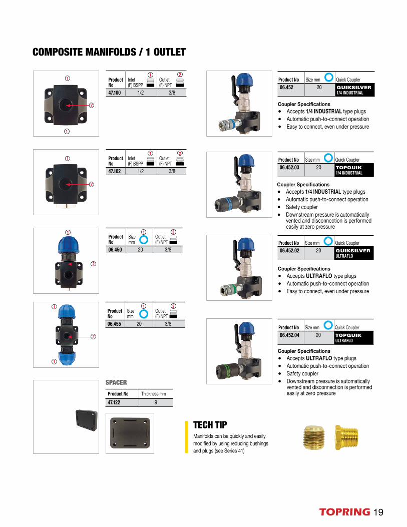
COMPOSITE MANIFOLDS / 1 OUTLET
Product No Size mm Quick Coupler06.452 20 QUIKSILVER
1/4 INDUSTRIAL
Coupler Specifications
• Accepts ULTRAFLO type plugs• Automatic push-to-connect operation• Easy to connect, even under pressure
Product No Size mm Quick Coupler06.452.02 20 QUIKSILVER
ULTRAFLO
Coupler Specifications
• Accepts 1/4 INDUSTRIAL type plugs• Automatic push-to-connect operation• Safety coupler• Downstream pressure is automatically
vented and disconnection is performed easily at zero pressure
Product No Size mm Quick Coupler06.452.03 20 TOPQUIK
1/4 INDUSTRIAL
Coupler Specifications
• Accepts ULTRAFLO type plugs• Automatic push-to-connect operation• Safety coupler• Downstream pressure is automatically
vented and disconnection is performed easily at zero pressure
Product No Size mm Quick Coupler06.452.04 20 TOPQUIK
ULTRAFLO
Product No Thickness mm47.122 9
SPACER
Product No
Inlet (F) BSPP
Outlet (F) NPT
47.102 1/2 3/8
Product No
Inlet (F) BSPP
Outlet (F) NPT
47.100 1/2 3/8
Product No
Size mm
Outlet (F) NPT
06.450 20 3/8
Product No
Size mm
Outlet (F) NPT
06.455 20 3/8
TECH TIPManifolds can be quickly and easily modified by using reducing bushings and plugs (see Series 41)

20 TOPRING
SPACERS FOR COMPOSITE MANIFOLD 2 OR 3 OUTLETS
2 2
1
2 2
1
1
22
1
1
2
2
1 2
COMPOSITE MANIFOLDS / 2 OUTLETS
Product No Thickness mm47.118 10 47.119 13 47.120 20
Product No
Inlet (F) BSPP
Outlet (F) NPT
47.108 1/2 1/2 (2x)47.110 3/4 1/2 (2x)
Product No
Inlet (F) BSPP
Outlet (F) NPT
47.109 1/2 1/2 (2x)47.111 3/4 1/2 (2x)
Product No
Size mm
Outlet (F) NPT
06.470 20 1/2 (2x)06.475 25 1/2 (2x)
Product No Size mm Quick Couplers06.461 20 QUIKSILVER
1/4 INDUSTRIAL (2x)06.462 25Coupler Specifications
• Accepts 1/4 INDUSTRIAL type plugs• Automatic push-to-connect operation• Easy to connect, even under pressure
Product No Size mm Quick Couplers06.461.04 20 TOPQUIK
ULTRAFLO (2x)06.462.04 25
Product No Size mm Quick Couplers06.461.02 20 QUIKSILVER
ULTRAFLO (2x)06.462.02 25Coupler Specifications
• Accepts ULTRAFLO type plugs• Automatic push-to-connect operation• Easy to connect, even under pressure
Coupler Specifications
• Accepts ULTRAFLO type plugs • Automatic push-to-connect operation• Safety coupler• Downstream pressure is automatically
vented and disconnection is performed easily at zero pressure
Product No Size mm Quick Couplers06.629 20 QUIKSILVER
ULTRAFLO (2x)06.630 25
Product No Size mm Quick Couplers06.626 20 TOPQUIK
ULTRAFLO (2x)06.627 25
F/R UNIT WITH COUPLERS
F/R UNIT WITH COUPLERS
F/R UNIT WITH COUPLERS
Product No Size mm Quick Couplers06.623 20 QUIKSILVER
1/4 INDUSTRIAL (2x)06.624 25
Includes: 5 micron F/R, safety lock-out valve, muffler, manifold with 2 couplers
Includes: 5 micron F/R, safety lock-out valve, muffler, manifold with 2 couplers
Includes: 5 micron F/R, safety lock-out valve, muffler, manifold with 2 couplers
LOCKOUT
LOCKOUT
LOCKOUT

TOPRING 21
2 2
2 2
1
22
1
1
2
2
2 2
1
2
2
1
1
2
2
1 2
1
1
2
2
Product No Size mm Quick Couplers 06.490 20 QUIKSILVER
1/4 INDUSTRIAL (3x)06.491 25
COMPOSITE MANIFOLDS / 3 OUTLETS
COMPOSITE MANIFOLDS / 4 OUTLETS
Product No
Size mm
Outlet (F) NPT
06.480 25 1/2 (3x)
Product No
Size mm
Outlet (F) NPT
06.487 20 1/2 (4x)06.489 25 1/2 (4x)
Coupler Specifications
• Accepts 1/4 INDUSTRIAL type plugs• Automatic push-to-connect operation• Easy to connect, even under pressure
Product No Size mm Quick Couplers 06.490.02 20 QUIKSILVER
ULTRAFLO (3x)06.491.02 25
Coupler Specifications
• Accepts ULTRAFLO type plugs• Automatic push-to-connect operation• Easy to connect, even under pressure
Product No Size mm Quick Couplers 06.490.04 20 TOPQUIK
ULTRAFLO (3x)06.491.04 25
Coupler Specifications
• Accepts ULTRAFLO type plugs• Automatic push-to-connect operation• Downstream pressure is automatically
vented and disconnection is performed easily at zero pressure
Product No
Inlet (F) BSPP
Outlet (F) NPT
47.115 1/2 1/2 (3x)47.113 3/4 1/2 (3x)
Product No
Inlet (F) BSPP
Outlet (F) NPT
47.114 1/2 1/2 (3x)47.112 3/4 1/2 (3x)
Product No
Inlet (F) BSPP
Outlet (F) NPT
47.150 1/2 1/2 (4x)47.155 3/4 1/2 (4x)
SPACER FOR COMPOSITE MANIFOLD 4 OUTLETS
Product No Thickness mm47.121 10
2 2
1
22

22 TOPRING
1
2
2 2
1
3
3 3
2
1 2
321
ALUMINIUM MANIFOLDS / 3 OUTLETS
Product No
Size mm
Outlet (F) NPT
06.435 20 1/4 (3x)06.436 25 3/8 (3x)06.437 32 1/2 (3x)
Product No
Inlet (F) BSPP
Outlet (F) BSPP
Outlet (F) NPT
47.307 3/4 3/4 3/8 (3x)47.310 3/4 3/4 1/2 (3x)47.320 1 1 1/2 (3x)
• Provides a convenient junction point for PIPING networks requiring multiple connections
• Universal manifolds with 3 outlets
Features and benefits
Product No
Size mm
Quick Coupler
06.441.03 20 TOPQUIK 1/4 INDUSTRIAL (3x)06.442.03 25
Product No
Size mm
Quick Coupler
06.441 20QUIKSILVER 1/4 INDUSTRIAL (3x)06.442 25
06.443 32
Coupler Specifications
• Accepts 1/4 INDUSTRIAL type plugs• Automatic push-to-connect operation• Easy to connect, even under pressure
Coupler Specifications
• Accepts 1/4 INDUSTRIAL type plugs• Automatic push-to-connect operation• Safety coupler• Downstream pressure is
automatically vented and disconnection is performed easily at zero pressure
Product No
Size mm
Quick Coupler
06.442.02 25 QUIKSILVER ULTRAFLO (3x)06.443.02 32
Product No
Size mm
Quick Coupler
06.442.04 25 TOPQUIK ULTRAFLO (3x)06.443.04 32
Coupler Specifications
• Accepts ULTRAFLO type plugs• Automatic push-to-connect operation• Easy to connect, even under pressure
Coupler Specifications
• Accepts ULTRAFLO type plugs • Automatic push-to-connect operation• Safety coupler• Downstream pressure is
automatically vented and disconnection is performed easily at zero pressure

TOPRING 23
When installing a line with different pipe diameters or when installing manifolds, the use of spacers is recommended for optimum alignment.
CLIP AND MANIFOLD SPACER COMBINATIONS FOR OPTIMAL PIPING ALIGNMENT ACCORDING TO PIPE DIAMETER
9 mm9 mm9 mm
9 mm9 mm 10 mm
20 mm
13 mm
13 mm
9 mm 13 mm No spacer required
10 mm
10 mm10 mm
MOUNTING CLIPS FOR RIGID PIPES
Product No Size mm06.541 2006.542 2506.543 3206.544 4006.545 5006.546 63
EPDM INSERT FOR FIXING PIPE CLIP
Product No06.548
Transforms a mounting clip into a fixed point bracket.
SPACER FOR MANIFOLD WITH 1 OUTLET
CLIP SPACER
06.549 Thickness 10 mm 47.122 Thickness 9 mm 47.121 Thickness 10 mm47.118 Thickness 10 mm 47.119 Thickness 13 mm 47.120 Thickness 20 mm
SPACER FOR MANIFOLD WITH 4 OUTLETS
SPACERS FOR MANIFOLD WITH 2 OR 3 OUTLETS
Recommended spacing
• A mounting clip should be installed at every 2 m maximum for all diameters (20 to 63 mm)
• A clip must be installed at 20 cm from a fitting (downstream or upstream)
Recommended screw: Round-headed screw number 14
Creating a fixed mounting bracketIn order to compensate for thermal expansion, create a fixed point by adding the EPDM insert inside the mounting pipe clip
24 TOPRING
06.499 / 06.496 / 06.497
06.498
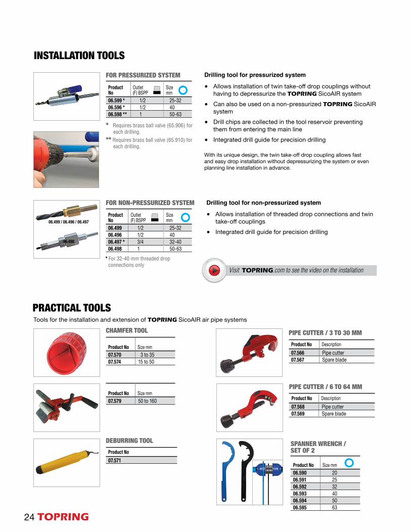
INSTALLATION TOOLSFOR PRESSURIZED SYSTEM
Product No
Outlet(F) BSPP
Size mm
06.599 * 1/2 25-3206.596 * 1/2 4006.598 ** 1 50-63
Product No
Outlet(F) BSPP
Size mm
06.499 1/2 25-3206.496 1/2 4006.497 * 3/4 32-4006.498 1 50-63
FOR NON-PRESSURIZED SYSTEM
Drilling tool for pressurized system
• Allows installation of twin take-off drop couplings without having to depressurize the TOPRING SicoAIR system
• Can also be used on a non-pressurized TOPRING SicoAIR system
• Drill chips are collected in the tool reservoir preventing them from entering the main line
• Integrated drill guide for precision drilling
Drilling tool for non-pressurized system
• Allows installation of threaded drop connections and twin take-off couplings
• Integrated drill guide for precision drilling
With its unique design, the twin take-off drop coupling allows fast and easy drop installation without depressurizing the system or even planning line installation in advance.
CHAMFER TOOL
SPANNER WRENCH / SET OF 2
DEBURRING TOOLProduct No07.571
Product No Size mm07.570 3 to 35 07.574 15 to 50
Product No Size mm07.579 50 to 160
Product No Size mm06.590 2006.591 2506.592 3206.593 4006.594 5006.595 63
PIPE CUTTER / 6 TO 64 MMProduct No Description07.568 Pipe cutter07.569 Spare blade
PIPE CUTTER / 3 TO 30 MMProduct No Description07.566 Pipe cutter07.567 Spare blade
PRACTICAL TOOLSTools for the installation and extension of TOPRING SicoAIR air pipe systems
* Requires brass ball valve (65.906) for each drilling.** Requires brass ball valve (65.910) for each drilling.
Visit TOPRING.com to see the video on the installation
* For 32-40 mm threaded drop connections only

TOPRING 25
MOUNTING ACCESSORIESSTRUT ADAPTER FOR MOUNTING CLIPS
Product No Description06.540 For all mounting
clips
CANTILEVER ARM 1-5/8" X 1-5/8"
Product No Length (in) 06.550 606.551 12
STRUT CHANNEL 1-5/8" X 1-5/8"
Product No Length (in) 06.555 10
THREADED ROD / 10 FTProduct No Size UNC06.526 3/8
COUPLING NUTProduct No Size UNC06.528 3/8
SCREW Product No Size UNC06.529 3/8
SUSPENSION PIPE CLIPS
SWIVEL LOOP HANGERS
-BEAM MOUNTING CLIPS
-BEAM CLAMP
Product No Size mmNut size UNC
06.503 20 3/806.508 25 3/806.513 32 3/806.518 40 3/806.519 50 3/8
Product No Size mmThreaded Rodsize UNC
06.510 25 3/806.514 32 3/806.516 40 3/806.521 50 3/806.522 63 3/8
Product No Beam Thickness (in)06.530 1/8 - 1/406.531 3/8 - 1/206.532 1/2 - 3/4
Product NoBeam Thickness (in)
Threaded Rodsize UNC
06.535 1/4 - 3/4 3/8

26 TOPRING
S49 •
S53 •
S54 •
S56 •
S57 •
S59 •
Clean and drycompressed air!Compressed air is a power source that is widely used throughout industry.
However, compressed air contains water, dirt, wearparticles and degraded lubricating oil, which all mixtogether to form an unwanted condensate.
This condensate rapidly wears tools and pneumaticmachinery, blocks valves and orifices and alsocorrodes piping.
This results in high maintenance costs and productspoilage which can bring the production processto an extremely expensive standstill.
Visitez TOPRING.com for more details on condensate management solutions:
Refrigerant Air Dryers
Compressed Air Filters
Desiccant Air Dryers
Water Separators
Water/Oil Separators
Condensate Drains

TOPRING 27
NOTES (square dimension .25 in)

Distributed by
TOPRING T 450 375-1828 / 1 800 263-8677
F 450 375-1408 [email protected] www.TOPRING.com1020, boulevard IndustrieGranby (Québec) J2J 1A4 Canada


