Comprehensive Micro Cabling Solutions and Installation Guide
28
Comprehensive Micro Cabling Solutions and Installation Guide
Transcript of Comprehensive Micro Cabling Solutions and Installation Guide

Comprehensive Micro Cabling Solutions and Installation Guide

Corning Optical Communications Micro Cabling Solutions and Installation Guide | LAN-2119-AEN | Page 2
What You Can Expect From This Guide
Micro cabling is an innovative approach to installing an optical network. Because it is different than traditional cable and duct
systems, it is important to ensure that you have a matched solution set to optimize the installation and final system for your needs
now and in the future.
The purpose of this solutions guide is to help you understand the required components, simplify product selection, and provide you
with the resources to get the job done right. Our hope is that by using this guide you will understand:
• The differences between traditional duct and microduct installations, as well as the advantages microducts enable.
• The key components of a micro cable and microduct installation.
• The micro cable installation process, recommended products, and how to obtain them.
• Novel deployment techniques for more challenging deployment scenarios.
Figure 1. Microduct installation Photo courtesy of Dura-Line

Corning Optical Communications Micro Cabling Solutions and Installation Guide | LAN-2119-AEN | Page 3
Table of Contents
Who is Corning? . . . . . . . . . . . . . . . . . . . . . . . . . . . . . . . . . . . . . . . . . . . . . . . . . . . . . . . . . . . . . . . . . . . . . . . . . . . . . . . . . . . . . . . . . . . . . . . . . . . . . . . . . . . . . . . . . 4
Understanding Micro Cabling Technology . . . . . . . . . . . . . . . . . . . . . . . . . . . . . . . . . . . . . . . . . . . . . . . . . . . . . . . . . . . . . . . . . . . . . . . . . . . . . . . . . . . . . . . . . 5
The Benefits of Micro Cabling Technology . . . . . . . . . . . . . . . . . . . . . . . . . . . . . . . . . . . . . . . . . . . . . . . . . . . . . . . . . . . . . . . . . . . . . . . . . . . . . . . . . . . . . . . . . 6
Is a Micro Cable and Microduct Solution the Right Choice for My Application? . . . . . . . . . . . . . . . . . . . . . . . . . . . . . . . . . . . . . . . . . . . . . . . . . . . . . 10
Understanding the Components of a Complete Micro Cable/Microduct Solution . . . . . . . . . . . . . . . . . . . . . . . . . . . . . . . . . . . . . . . . . . . . . . . . . . . 11
• Fiber Selection . . . . . . . . . . . . . . . . . . . . . . . . . . . . . . . . . . . . . . . . . . . . . . . . . . . . . . . . . . . . . . . . . . . . . . . . . . . . . . . . . . . . . . . . . . . . . . . . . . . . . . . . . . . . . . 11
• Cable Selection . . . . . . . . . . . . . . . . . . . . . . . . . . . . . . . . . . . . . . . . . . . . . . . . . . . . . . . . . . . . . . . . . . . . . . . . . . . . . . . . . . . . . . . . . . . . . . . . . . . . . . . . . . . . . . 11
• Microduct Selection . . . . . . . . . . . . . . . . . . . . . . . . . . . . . . . . . . . . . . . . . . . . . . . . . . . . . . . . . . . . . . . . . . . . . . . . . . . . . . . . . . . . . . . . . . . . . . . . . . . . . . . . . 14
• Closures . . . . . . . . . . . . . . . . . . . . . . . . . . . . . . . . . . . . . . . . . . . . . . . . . . . . . . . . . . . . . . . . . . . . . . . . . . . . . . . . . . . . . . . . . . . . . . . . . . . . . . . . . . . . . . . . . . . 16
• Hardware . . . . . . . . . . . . . . . . . . . . . . . . . . . . . . . . . . . . . . . . . . . . . . . . . . . . . . . . . . . . . . . . . . . . . . . . . . . . . . . . . . . . . . . . . . . . . . . . . . . . . . . . . . . . . . . . . . . 17
• Splicing . . . . . . . . . . . . . . . . . . . . . . . . . . . . . . . . . . . . . . . . . . . . . . . . . . . . . . . . . . . . . . . . . . . . . . . . . . . . . . . . . . . . . . . . . . . . . . . . . . . . . . . . . . . . . . . . . . . . . 17
Installing a Micro Cable/Microduct System . . . . . . . . . . . . . . . . . . . . . . . . . . . . . . . . . . . . . . . . . . . . . . . . . . . . . . . . . . . . . . . . . . . . . . . . . . . . . . . . . . . . . . . . 18
• Considerations When Installing a Micro Cable/Microduct System . . . . . . . . . . . . . . . . . . . . . . . . . . . . . . . . . . . . . . . . . . . . . . . . . . . . . . . . . . . . . 18
• Initial Planning . . . . . . . . . . . . . . . . . . . . . . . . . . . . . . . . . . . . . . . . . . . . . . . . . . . . . . . . . . . . . . . . . . . . . . . . . . . . . . . . . . . . . . . . . . . . . . . . . . . . . . . . . . . . . . 18
• Blowing Equipment and Accessories . . . . . . . . . . . . . . . . . . . . . . . . . . . . . . . . . . . . . . . . . . . . . . . . . . . . . . . . . . . . . . . . . . . . . . . . . . . . . . . . . . . . . . . . 20
• Unique Installation Methods . . . . . . . . . . . . . . . . . . . . . . . . . . . . . . . . . . . . . . . . . . . . . . . . . . . . . . . . . . . . . . . . . . . . . . . . . . . . . . . . . . . . . . . . . . . . . . . 22
What to Look for in a Contractor . . . . . . . . . . . . . . . . . . . . . . . . . . . . . . . . . . . . . . . . . . . . . . . . . . . . . . . . . . . . . . . . . . . . . . . . . . . . . . . . . . . . . . . . . . . . . . . . . 25
• Network of Preferred Installers (NPI) and Checklist . . . . . . . . . . . . . . . . . . . . . . . . . . . . . . . . . . . . . . . . . . . . . . . . . . . . . . . . . . . . . . . . . . . . . . . . . . . 25
Quick Links to Available Resources . . . . . . . . . . . . . . . . . . . . . . . . . . . . . . . . . . . . . . . . . . . . . . . . . . . . . . . . . . . . . . . . . . . . . . . . . . . . . . . . . . . . . . . . . . . . . . 26
Glossary and Conversions . . . . . . . . . . . . . . . . . . . . . . . . . . . . . . . . . . . . . . . . . . . . . . . . . . . . . . . . . . . . . . . . . . . . . . . . . . . . . . . . . . . . . . . . . . . . . . . . . . . . . . . 27

Corning Optical Communications Micro Cabling Solutions and Installation Guide | LAN-2119-AEN | Page 4
The world gets more connected every day. High-speed networks are bringing people together across oceans and deserts, turning miles into milliseconds, kilometers into kilobytes. We enable much of this connectivity. We are Corning.
Spanning a broad range of end-to-end fiber solutions for communications networks, our products form the backbone that connects businesses, homes, and people around the globe. Our fiber-to-the-everywhere technologies support virtually unlimited bandwidth through high-capacity optical and wireless connections. Backed by an unparalleled commitment to always-
fast, always-there customer care, our solutions deliver premium performance at the industry’s most attractive total cost of ownership.
At Corning, we’re not satisfied just creating the best optical communications technologies. We’re constantly pushing the limits of connectivity speed and reliability. As the inventor of the first commercially viable low-loss optical fiber, no one understands how to provide brilliant connections for tomorrow, today, quite like we do.
Who is Corning?
Innovation
• 160 years of materials science and process engineering knowledge
• 40+ years of telecom industry expertise
– Corning scientists invented the first low-loss optical fiber in 1970
• ~10% of revenue invested in R&D
– Corning’s patent portfolio ranked 1st in Industrial Materials on The Patent Scorecard™ since 2007
• Problems solved through innovation and engagement with our customers
Services & Support
• Dedicated Engineering Services group with 50+ engineers ready to provide:
– 24/7 technical support
– Field support
– System/network design
• Experienced system engineers provide design support for any network application
• Product and market knowledge for system upgrades/optimization
Quality
• Global network of world-class manufacturing facilities
• The most widely-deployed brand ofoptical fiber in the world
– 1.5 billion km deployed worldwide
• Quality architecture ensures most consistent, high-quality products
• Focus on continuous improvement
Table 1.

Corning Optical Communications Micro Cabling Solutions and Installation Guide | LAN-2119-AEN | Page 5
Micro cables are miniaturized stranded loose tube (LT) cables that offer a 50 percent reduction in size and a 70 percent reduction in weight, with the same functionality as standard loose tube cables. Miniaturization is achieved through a reduction in buffer tube diameter (typically from approximately 2.5 mm to 1.4 mm in the case of MiniXtend® cables with binderless* FastAccess® technology), which in turn enables higher per-cable fiber density. However, this also means that micro cables are less rugged than standard LT cables.
Whereas one or multiple standard LT cables can be deployed in a single duct, micro cables must be deployed in microducts for added protection. Far from being an inconvenience, microducts divide internal duct space into smaller compartments into which micro cables are installed, enabling greater per-duct fiber density, lower deployment costs (through the avoidance of costly traditional construction methods), and scalable capacity. Installing multiple standard LT cables into a duct during initial installation or incrementally in the future can lead to more challenging installations and reduced installation distances.
Micro cables and microducts are designed to work together to provide a very effective, efficient way to deploy a passive optical infrastructure. To ensure safe cable placement, only blowing equipment and cable handling techniques specifically designed for micro cables should be used. Handling micro cables in the same manner as traditional loose tube cables can cause cable damage and potentially costly delays.
Understanding Micro Cabling Technology
ALTOS® Cable, 144 F(2.5 mm buffer tubes)
14.9 mm, 165 kg/km
MiniXtend® Cable, 144 F(1.4 mm buffer tubes)
8.1 mm, 53 kg/km
Deployment
Single cable deployed in single duct
Micro cables deployed in single/bundled microducts
1.25-in duct 7 x 12.7/10 mmmicroduct bundle
Figure 1. Comparison of standard 144-fiber loose tube cable to a 144-fiber MiniXtend cable
Figure 2. Comparison of single cable deployed in a single duct to micro cables installed in a 7-way duct
* Corning’s patented binderless FastAccess® technology refers to the combination of a Corning FastAccess technology jacket with an innovative technology used to bind cable construction through the manufacturing process eliminating the use of binder yarns and waterblocking tapes.

Corning Optical Communications Micro Cabling Solutions and Installation Guide | LAN-2119-AEN | Page 6
Higher Fiber Density
Micro cables allow for much higher fiber density in a given cross-sectional area of cable. Corning’s smallest standard loose tube cable has an outer diameter of 10.5 mm and a maximum fiber count of 72. In comparison, by using 1.4 mm buffer tubes (instead of 2.5 mm tubes), 144-fiber MiniXtend® cable with binderless FastAccess® technology contains twice as many
Improved Cable Handling
Micro cables are up to 70 percent lighter than traditional loose tube cables. This facilitates improved cable handling and allows networks to be installed by smaller crews.
fibers with a 20 percent reduction in cable outer diameter. To provide even more efficiency, with 24 reduced-diameter 200 μm fibers per 1.7 mm buffer tube, MiniXtend HD cable provides 200 percent more fibers than the 72-fiber loose tube cable.
This higher per-cable fiber density translates to higher per-duct fiber density when micro cables are combined and installed in
specifically designed multipath microduct bundles. In the U.S., the most common duct has an inner diameter (ID) of 1.25 in. The largest standard loose tube cable that can fit inside this duct has a fiber count of 432. If an operator were to instead deploy a 7-way microduct bundle with 12.7/10.0 (OD/ID) microducts, they could install seven 144-fiber standard micro cables and benefit from 133 percent more fibers. For even greater fiber density, the operator could install seven 216-fiber MiniXtend HD cables for 250 percent more fibers than the traditional cable and duct.
The Benefits of Micro Cabling Technology
Loose Tube (LT) Cable MiniXtend® Cablew/Binderless* FastAccess® Technology
144 FMiniXtend HD
Cable, 216 F10.5 mm 8.1 mm 8.0 mm
72 FIBERS 100% MORE FIBERS 200% MORE FIBERS
Per C
able
Fibe
r Den
sity
Fiber Count ALTOS® Cables MiniXtend Cables MiniXtend HD Cables
Total FC Weight (lb/1000 ft) Weight (lb/1000 ft) Weight (lb/1000 ft)
72 49 15
96 66 24
144 109 38 25
192 99 37
216 99 40
288 131 56
Figure 3. Comparison of standard loose tube cable, MiniXtend cable, and MiniXtend HD cable
Figure 4. Comparison of standard loose tube/standard duct, MiniXtend/microduct, and MiniXtend HD/microduct
Table 2. Comparison of weights for equivalent ALTOS standard loose tube cable, MiniXtend cable, and MiniXtend HD cables.
7 x 144 = 1008 F 7 x 216 = 1512 F
1.25-in(ID)
1.64-in 1.64-in
432 FIBERS(max. LT fiber count)
133% More Fibers 250% More Fibers
Per -
Duc
tFi
ber D
ensi
ty

Corning Optical Communications Micro Cabling Solutions and Installation Guide | LAN-2119-AEN | Page 7
Moreover, smaller, lighter cables mean smaller, lighter transportation reels that can be moved and stored with a much smaller footprint.
Alternatively, longer cable lengths can be accommodated on standard transportation reels. Longer delivery lengths can translate to longer blowing lengths and fewer splice points when the installation is designed properly.
Scalability and Flexibility
When investing new fiber capacity, it can be difficult to ensure that a cable installed today will satisfy your future fiber needs. Addressing this challenge, multipath microduct bundles offer scalable capacity and the ability to add new cables as and when they are needed without having to install a very-high-fiber-count cable on day one, or pay for costly civil works in the future
Final installation of three additional 144 F cables7 x 144 F = 1,008 F
Future installation of two additional 144 F cables. Totalcapacity 4 x 144 F = 576 F
– as would be the case with traditional loose tube cables. Consider a network route that requires 288 fibers on day one. This could easily be accomplished by using either a 288-fiber LT cable in a standard duct or by using two 144-fiber micro cables in a microduct bundle, where installation costs would be very similar for placing the ducts. The cost differential between the installations would be the extra microduct investment up front and the installation of the two separate 144-fiber micro cables.
However, the true value of micro cables and microducts is evident when the fiber requirement exceeds the initial 288 fibers. To add LT capacity would require construction of a new duct pathway at significant cost. But with micro cables, you have the ability to install up to 720 more fibers in your five vacant microducts, incurring only the cost to purchase and blow the new micro cables.
Max. capacity = 1 x 288 F cable
Duct (ID)1.25 in/33 mm Cable (OD)
18.2 mm
Initial installationtwo 144-F cablesTotal capacity 2 x 144 F = 288 F
Figure 7. Standard 288-fiber loose tube cable placed in a standard duct compared to two 144-fiber cables placed in a microduct system
Figure 8. Upgrade path utilizing a 144-fiber cable in microducts
Figure 6. Payout of a 144-fiber MiniXtend cable
Figure 5. Comparison of equivalent reel diameters for a standard loose tube and a MiniXtend cable

Corning Optical Communications Micro Cabling Solutions and Installation Guide | LAN-2119-AEN | Page 8
Future Installation Cost Savings
It is important in any system installation to understand your first-installed cost against the cost of future deployments. We have done extensive modeling to understand the cost of a standard loose tube cable installation against a micro cable and microduct installation. In this example, we compare the cost of building a 40-km metro network using standard loose tube cables and traditional open trenching to various alternative methods that use microducts and micro cables (which are discussed later in this guide). In terms of first-installed costs, there is little difference between the open-trenched loose tube and micro cable scenarios, due to the invasive nature of the procedure and the high cost of permits required to dig in an urban location.
Table 3. Comparison of standard duct and loose cable to micro cable and 7-way microduct solution, first-installed cost, and cable overlay cost
Cost
$M
FI RST-I NSTALLEDCOSTS*
FI BER CAPACITYCABLE OVERLAY COSTCOMPARISON*
CableDuctCivils
Open-trenched
1.25-in ducts + LT cable
Open-trenched
1.25-in ducts + LT cable
Microduct overlay
into 1.25-in ducts
+ micro cable
Maximum �bers96
Gray = existing infrastructureColor = new infrastructure
Maximum �bers672
LT cable blown
into existing
1.25-in ductOpen-tre
nched
7-way microduct
bundle + micro cableMicro cable blown
into existing microduct
(bundle or �atline)

Corning Optical Communications Micro Cabling Solutions and Installation Guide | LAN-2119-AEN | Page 9
The true value of microduct and micro cable technology is revealed when we compare the cost of cable overlays and increasing this day-one capacity. With a 6- or 7-way microduct bundle in place, increasing capacity will entail only the cost to purchase and blow in a new micro cable. By the same token, with one vacant 1.25-in duct the cost for the first standard loose tube overlay will be very similar. Any further increases will be more complicated and more expensive, with microduct overlays being the only way to avoid 40 km of retrenching.
Table 4. Total cost of ownership of standard duct vs. 7-way microduct over a 20-year expected life
1 2 3 4 5 6 7 8 9 10 11 12 13 14 15 16 17 18 19 200
100
200
300
400
500
600
700
800
Year
Cost
$M
Fibers Lit
ASSUMPTIONS
96 F cable + empty1.25-in duct
96 F/micro cable
30% compound annual growth rate (CAGR) capacity demand growth:
• 15% provisioned by data rate upgrades
• 15% provisioned by ber
192 �bers lit new cable + duct + retrench requiredOpen-trenched 1.25-in mm ducts + LT cable
672 �bers lit new cable + duct + retrench requiredOpen-trenched 7-way microduct bundle + micro cable
384 �bers lit new cable + duct + retrench requiredOpen-trenched 7-way microduct bundle + micro cable (2-way cons.)
Microtrenching represents lowest-cost civil worksMicrotrenched 6-way �atline bundle + micro cable
MiniXtend® Cables and microducts enable lowest lifetime network cost
MiniXtend® cables and microducts enable lowest lifetime network costs
Corning Optical Communications Micro Cabling Solutions and Installation Guide | LAN-2119-AEN | Page 10
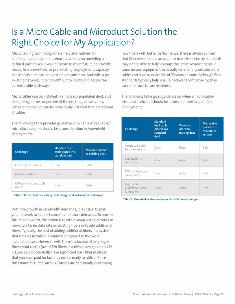
new fibers with better performance, there is always concern that fiber developed in accordance to earlier industry standards may not be able to fully leverage the latest advancements in transmission equipment, especially when many outside plant cables can have a service life of 25 years or more. Although fiber standards typically help ensure backward compatibility, they cannot ensure future readiness.
The following table gives guidance on when a micro cable/microduct solution should be a consideration in greenfield deployments.
Micro cabling technology offers new alternatives for challenging deployment scenarios, while also providing a defined path to scale your network to meet future bandwidth needs. In a brownfield, or pre-existing, deployment, capacity constraints and duct congestion are common. And with a pre-existing network, it can be difficult to locate and access the current cable pathways.
Micro cables can be installed in an already populated duct, and depending on the congestion of the existing pathway, new cables or microduct can be more easily installed than traditional LT cables.
The following table provides guidance on when a micro cable/microduct solution should be a consideration in brownfield deployments.
With the growth in bandwidth demands, it is critical to plan your network to support current and future demands. To provide future bandwidth, the option is to either swap out electronics to move to a faster data rate on existing fibers or to add additional fibers. Typically, the cost of adding additional fibers in a system that is being installed is minimal compared to the overall installation cost. However, with the introduction of very-high-fiber-count cables (over 1,728 fibers in a ribbon design, up to 432 LT), you could potentially have significant dark fiber in places that you have paid for but may not be ready to utilize. Since fiber manufacturers such as Corning are continually developing
Is a Micro Cable and Microduct Solution the Right Choice for My Application?
ChallengeStandard duct cable placed in a standard duct
Microduct added to existing duct
Capacity constraints Good Better
Duct congestion Good Better
Difficult-to-access cable routes Good Better
Table 5. Brownfield or existing cable design and installation challenges
Challenge
Standard duct cable placed in a standard duct
Microduct added to existing duct
Microcable placed in microduct system
Needs to be able to scale capacity Good Better Best
Segregation of networks Good Better Best
Difficult-to-access cable routes Good Better Best
High cable installation costs & slow ROI
Good Better Best
Table 6. Greenfield cable design and installation challenges

Corning Optical Communications Micro Cabling Solutions and Installation Guide | LAN-2119-AEN | Page 11
Cable Selection
Corning offers two innovative products as part of our MiniXtend cable portfolio. Standard-density MiniXtend cables with binderless FastAccess technology are available with fiber counts ranging from 12 to 144 fibers.
This product set not only offers high density in a small footprint, but it also enables advanced cable access to make installations easier and faster, while limiting the need for sharp-bladed tools. Our FastAccess technology enables up to 70 percent faster cable and fiber access, achieved through a jacket design that can be simply peeled away with the use of the ripcord. This design also reduces the risk of damage to the buffer tubes and fibers because no sharp tools are needed to access the cable core.
Fiber Selection
Fiber selection is one of the most important decisions you can make when designing your passive optical network. Corning has been at the forefront of the optical transmission industry since inventing the first commercially viable low-loss fiber in 1970. As optical fiber became the clear choice for growing bandwidth requirements, network operators were faced with new challenges — extend optical reach at very high data rates and make networks scalable for higher capacities. We responded by being the first to develop a variety of optical fiber products to meet specific installation challenges: ultra-low-loss optical fiber, bend-insensitive optical fiber, and Corning® SMF-28® Ultra optical fiber, which combined the benefits of industry-leading attenuation and improved macrobend performance.
Operators are still looking for solutions to address increasing bandwidth and capacity demands. SMF-28 Ultra optical fiber combined with our MiniXtend® cable with binderless FastAccess® technology create greater per-cable fiber density and greater fiber density for a given duct size.
This enables:
• Greater network capacity
• Fiber deployments deeper in the network
• Lower installation cost
Understanding the Components of a Complete Micro Cable/Microduct Solution
MiniXtend Cables with Binderless*FastAccess Technology
8.1mm6.3
mm5.4mm
12-72 F 96 F 144 F
Corning® SMF-28®Ultra fiber
Corning®SMF-28e+® fiber
AttributeTypicalCabledAttenuation
Maximum CabledAttenuation
Typical CabledAttenuation
Maximum CabledAttenuation
1310 nm(dB/km) ≤ 0.32 ≤ 0.34 ≤ 0.33 ≤ 0.35
1550 nm(dB/km) ≤ 0.18 ≤ 0.22 ≤ 0.19 ≤ 0.20
�
�
�
�Table 7. Fiber specifications
Figure 8. MiniXtend cables with binderless FastAccess technology by fiber count

Corning Optical Communications Micro Cabling Solutions and Installation Guide | LAN-2119-AEN | Page 12
Binderless Design
• SZ-stranded cable without binder(s) or ripcord(s).
• Binderless design enables quick and easy access to buffer tubes.
Traditional Advanced
End
-spa
n M
id-s
pan
Traditional Advanced
Binderless Design
• SZ-stranded cable without binder(s) or ripcord(s).
• Binderless design enables quick and easy access to buffer tubes.
Traditional Advanced
End
-spa
n M
id-s
pan
Traditional Advanced With the innovative binderless design, the cable jacket can be easily peeled open to reveal buffer tubes ready for immediate use. With cables having to be opened more frequently as fiber is driven deeper into the network, these features reduce cable access time by as much as 70 percent.
These features also enable faster and safer mid-span cable access. After the initial ring cut performed during a mid-span access, the jacket can be split and removed using simple hand tools. The binderless design also eliminates the need to remove each binder with a sharp tool such as a seam ripper.
MiniXtend® cables with binderless FastAccess technology are available in the following configurations:
Fiber Count Fiber Type Jacket Configuration Length Markings
12 Bend-Insensitive Single-Mode (OS2) Duct Meters 012ZM4-T3F22A20
12 Feet 012ZM4-T4F22A20
24 Meters 024ZM4-T3F22A20
24 Feet 024ZM4-T4F22A20
36 Meters 036ZM4-T3F22A20
36 Feet 036ZM4-T4F22A20
48 Meters 048ZM4-T3F22A20
48 Feet 048ZM4-T4F22A20
72 Meters 072ZM4-T3F22A20
72 Feet 072ZM4-T4F22A20
96 Meters 096ZM4-T3F22A20
96 Feet 096ZM4-T4F22A20
144 Meters 144ZM4-T3F22A20
144 Feet 144ZM4-T4F22A20
1
Figure 9. Advanced stripping process starts with commonly used hand tools to initiate jacket peel
2
Figure 10. Cable jacket then simply pulled apart to required stripping length
Figure 11. Traditional vs. advanced binderless design cable end access
Figure 12. Traditional vs. advanced binderless design cable mid-span access
Table 8. Cable configurations

Corning Optical Communications Micro Cabling Solutions and Installation Guide | LAN-2119-AEN | Page 13
To prepare for future network demands, we have also developed MiniXtend® HD cables: high-density 144- to 288-fiber micro cables that are up to 60 percent smaller and up to 70 percent lighter than standard loose tube cables. MiniXtend HD cables utilize SMF-28® Ultra 200 fiber, which offers a unique combination of low loss, improved bend, and an 8.2 micron core diameter for total compatibility with legacy optical fiber cables.
We achieved this remarkable density by combining our advanced cabling and fiber development technologies. By using a smaller-coating-diameter fiber (SMF-28 Ultra 200), higher fiber counts can be placed in the same space of a standard MiniXtend cable. The fiber still retains the 125 µm glass cladding diameter for G.652 and G.657 interoperability, but utilizes a thinner protection coating. The result is an industry-leading combination of low-loss and G.657.A1 bend that retains total compatibility with legacy G.652.D fibers in a smaller area.
MiniXtend HD cables are currently available in the following configurations. Note that MiniXtend HD cables are not available with binderless FastAccess® technology and are configured with 24 fibers per buffer tube. Because the buffer tubes contain 24 fibers, you must pay attention to the fiber color and marking to identify each fiber correctly.
Read more about fiber color coding in Corning optical cables here.
Introducing …
Corning® SMF-28®Ultra 200 fiber
288 F216 F192 F144 F
9.7mm8.0
mm7.5mm6.3
mm
Coating200 µm(nominal)
SMF-28 Ultra 200 fiber
Conventional G.652.D fiber
Coating242~245 µm(nominal)
Cladding
125 µm
Core
8.2 µm
Fiber Position Fiber Color Fiber Marker
1 Blue None
2 Orange None
3 Green None
4 Brown None
5 Slate None
6 White None
7 Red None
8 Black None
9 Yellow None
10 Violet None
11 Rose None
12 Aqua None
13 Blue Black Ring Marker
14 Orange Black Ring Marker
15 Green Black Ring Marker
16 Brown Black Ring Marker
17 Slate Black Ring Marker
18 White Black Ring Marker
19 Red Black Ring Marker
20 Natural Black Ring Marker
21 Yellow Black Ring Marker
22 Violet Black Ring Marker
23 Rose Black Ring Marker
24 Aqua Black Ring Marker
MiniXtend® HD Cables
Figure 13. MiniXtend HD cable by fiber count
Figure 14. Comparison of conventional G.652.D fiber and Corning SMF-28 Ultra 200 fiber
Table 9. MiniXtend HD fiber identification scheme

Corning Optical Communications Micro Cabling Solutions and Installation Guide | LAN-2119-AEN | Page 14
Microduct Selection
Microducts can be ordered individually, or in factory-installed multipath bundles. The choice between those two options depends on your deployment scenario and your current and future fiber capacity needs. Some of the microduct options currently available are listed below.
Single/Loose Microducts
• Ideal for override into occupied ducts or direct-buried (requires thicker microduct wall)
• Enables optimized use of limited duct space
• Provides flexibility and scalability
Microduct Bundles
• Multiple microducts bound with an oversheath (factory installed)
• Fixed configurations (2, 4, 7 microducts, etc.)
• Enables future capacity and ease of placement installation in sub-ducts/direct burial
Flat Line Microducts
• Multiple microducts joined by thin “web” of high-density polyethylene (HDPE)
• Facilitates placement in micro trenches or rolling around existing cables in congested ducts
• Microducts can be easily separated for routing of individual cables
Fiber Count Fiber Type Cable Type Part Number
144 Corning® SMF-28® Ultra 200 fiber Dielectric 144ZHA-Y4104A20
192 192ZHA-Y4104A20
216 216ZHA-Y4104A20
288 288ZHA-Y4104A20
Table 10. Available MiniXtend HD configurations
Figure 15.
Figure 16.
Figure 17.
Figure 18. Photo courtesy of Dura-Line
Photo courtesy of Dura-Line
Photo courtesy of Dura-Line

Corning Optical Communications Micro Cabling Solutions and Installation Guide | LAN-2119-AEN | Page 15
Microduct sizes are called out using the outer and inner diameter specifications. A commonly used microduct size is 12.7/10, which means an outer diameter of 12.7 mm and an inner diameter of 10 mm.
The MiniXtend family of cables will work with many different sizes of microduct, available from many duct suppliers. Corning has consulted with a number of microduct manufacturers to provide general guidance on the optimum duct size and smallest compatible microducts for each product in the portfolio.
For optimum blowing or jetting performance, we recommend a fill ratio of 50 to 80 percent between the outer diameter of the micro cable and the inner diameter of the microduct. Fill ratio should be calculated using the formula “d/D” whereby “d” is the outer diameter of the micro cable and “D” is the inner diameter of the microduct. For more information, read Corning’s Applications Engineering Note 049. This will enable the necessary airflow to achieve the required installation distance. Because of the cable jetting installation methods, too low of a fill ratio may not allow enough airflow to properly jet the cables over the required distance. We recommend calculating fill ratio as shown in Figure 31A for cables being jetted in.
For information on the performance of MiniXtend cables in a specific duct combination, contact Corning directly.
Figure 19. Microduct naming convention
Figure 19A. Conduit fill ratio calculation for blowing cable
12.7mm
D
10.0mm
Duct
Cable
d
d = Cable diameterD = Duct inner diameter
Fill Ratio = x 100d
D

Corning Optical Communications Micro Cabling Solutions and Installation Guide | LAN-2119-AEN | Page 16
Closures
In a micro cable/microduct system, careful planning is necessary to take advantage of the flexibility and scalability of the solution. With the potential fiber densities, it is possible to support more than 2,000 fibers in a duct less than two inches in inner diameter. When planning your network build, it is important to design your system so that your choices in hardware and closures can scale to support the fiber densities your network may see over time. In the outside plant, splice points could be placed below grade using closures placed in handholes, or above grade in a hut. In either deployment scenario, there are products available that can provide both the flexibility and scalability required to support a growing network.
When determining which closure is the best fit for your application, you should determine if you will splice multiple MiniXtend cables into a single closure or segregate your network and use a separate splice closure for each microduct. As an example, if you deployed a 288-fiber MiniXtend HD cable in a 7-way microduct bundle configuration, in time you will have a splice point with seven different splice closures. The necessary slack must be properly stored and protected. This would require either a communications hut, a vault, or seven different hand-holes. If you did not plan properly and installed a closure not designed to support that density, it could be much more difficult to accommodate the additional closures over time.
Corning offers a variety of closures that are compatible with our MiniXtend cable portfolio. The following table provides information on one of our most popular closure offerings used in micro cable splicing.
For a more complete discussion of closure options, reference Micro Cable Closure Review.
Fiber Count 12-72 F 96 F 144 F
Cable OD 5.4 mm 6.3 mm 8.1 mm
Smallest Duct ID(fill ratio)
8.0 mm(68%)
8.0 mm(79%)
10.0 mm(81%)
Optimal Duct ID(fill ratio)
10.0 mm(54%)
10.0 mm(63%)
12.0 mm(68%)
144 F 192 F 216 F 288 F
6.3 mm 7.5 mm 8.0 mm 9.7 mm
8.0 mm(79%)
10.0 mm(75%)
10.0 mm(80%)
12.0 mm(81%)
10.0 mm(63%)
12.0 mm(63%)
12.0 mm(67%)
14.0 mm(69%)
MiniXtend® CablesWith Binderless* FastAccess® Technology MiniXtend® HD Cables
Cable OD Fiber Count(s) Full Splice Buried Grommet Kit
5.4 mm 12 to 72 SCF-6C22-01-F SCF-KT-G62-6
6.3 mm 96,144 SCF-6C28-01-F SCF-KT-G62-6
7.5 mm 192 SCF-6C28-01-F SCF-KT-G62-6
8.1 mm 144, 216 SCF-8C28-01-F SCF-KT-G82-6
9.7 mm 288 SCF-8C28-01-F SCF-KT-G83-11
Table 11. Fill ratio calculation
Table 12. Closure compatibility

Corning Optical Communications Micro Cabling Solutions and Installation Guide | LAN-2119-AEN | Page 17
Compatibility of hardware and closures with smaller diameter micro cables is critical to maintain proper sealing and cable entry. Closures should be able to accommodate cables with smaller diameters either through the correct grommets or other sealing. Most splice trays are optimized for typical buffer tube sizes found in standard loose tube cables. In selecting the correct splice tray, it is important to understand if there is an option designed for micro cables or if there is a manufacturer-approved method for securing micro cable buffer tubes in a tray designed for standard size buffer tubes. We recommend the use of our ribbon strain-relief kit (p/n 365459), commonly used to secure fiber ribbons in a splice tray, to properly secure the smaller MiniXtend® buffer tubes.
HardwareFor above-ground installations, you should determine if fibers need to be dropped at the splice location. If through-splicing is the only requirement, then closures or products such as the optical splice wall-mountable enclosure could provide high-fiber-count splicing.
For above-ground applications where cables or individual fibers are dropped, products that can accommodate splicing and connectorization are the best choice. Hardware solutions such as Corning’s Centrix™ or rack-mounted closet connector housings (CCH) can provide flexibility and scalability. The following table lists options well suited for micro cable installations.
Splicing
With the potential for thousands of fibers in a micro cable system, splicing time should be factored in when estimating the total installation time. In a micro cable, loose fibers can be
spliced one by one, or they can be ribbonized in multiples of 12 to enable mass-fusion splicing and significantly reduce overall splicing time. Ribbonizing is a long-standing, common process but it does require specialized equipment and training. Corning offers a tool kit (TKT-026-01A) that includes a specialized jig and tape to enable ribbonizing. You can find more product information here. For ribbonizing and splicing, 200 µm coated fiber, please contact Corning directly.
If you choose to ribbonize the fibers in a micro cable, ensure that your closure and rack-mounted or wall-mounted selections are compatible with splice trays specifically designed for ribbon splicing.
Furthermore, if you are using MiniXtend HD cables, remember that the fiber coating has a diameter of 200 µm and not ~242 µm. While this should not cause splicing issues, as Corning® SMF-28® Ultra 200 fiber maintains the 9.2 µm mode-field diameter of standard G.652.D fibers, it is advisable to work with your splicing contractor or splicing equipment manufacturer to ensure that you have the right accessories to splice 200 µm fiber. Also make sure you use splice trays that can accommodate 24 fibers per buffer tube, such as the single-fiber splice tray (SCF-ST-112). Learn more.
Grommet Buffer Tube
Ribbon Grommet
Product Family Description Product Detail Part Number
Centrix Splice housing,pigtailed
1U, Three cassettes each with 24 LC APC adapters and single-mode pigtails, MIC® 900 µm standard single-mode pigtails, total of 72 F
CX172P24-B3-2RH000
Centrix Splice housing,pigtailed
2U, Six cassettes each with 24 LC UPC adapters and single-mode pigtails, MIC 900 µm standard single-mode pigtails, total of 144 F
CX2E4P24-A9-2RH000
Centrix Splice housing,pigtailed
4U, 12 cassettes each with 24 LC APC adapters and single-mode pigtails, MIC 900 µm standard single-mode pigtails, total of 288 F
CX4U8P24-B3-2RH000
CCH Closet connectorhousing
One rack, holds two CCH connector panels CCH-01U
CCH Closet connectorhousing
Two rack units, holds four CCH connector panels CCH-02U
CCH Closet connectorhousing
Three rack units, holds six CCH connector panels CCH-03U
CCH Closet connectorhousing
Four rack units, holds 12 CCH connector panels CCH-04U
CCH CCH pigtailedsplice cassette
12 F, LC UPC duplex, single-mode (OS2), single-fiber (250 µm) CCH-CS12-A9-P00RE
Figure 20. Ribbon strain-relief kit
Table 13. Table-hardware recommendations

Corning Optical Communications Micro Cabling Solutions and Installation Guide | LAN-2119-AEN | Page 18
Considerations When Installing a Micro Cable/Microduct System
Micro cable is designed to be blown and pushed through a microduct using specially designed equipment. Although a micro cable can be pulled through a duct as a standard loose tube cable, it is severely limited because the maximum acceptable tensile load rating is much lower. As an example, Corning’s 72-fiber ALTOS® loose tube, gel-free, all-dielectric cable with FastAccess® technology has a short-term tensile rating of 600 lbf/2700 N. The equivalent micro cable product, 72-fiber MiniXtend® cable with binderless* FastAccess technology, has a short-term tensile rating of 78 lbf/350 N. Because of this, we recommend that all micro cable installations are blown in and never pulled.
It is critical to think through your typical cable handling practices before you start installing. Identify areas where the cable is being blown, stored, and secured and determine if any of your current practices could potentially damage a micro cable. One example would be when working with closures. In many installations involving splicing in a closure, the closure is moved by holding the cable at the end cap and the closure body. If during placement the closure is held in one hand by the cables alone, it could cause a bend in the cable because of the weight of the closure.
Everyone handling the cable should be trained on any areas of concern. Likewise, because of the smaller diameter of micro cables, you can take advantage of the cable design during install. The minimum bend-radius of 72-fiber MiniXtend cable with binderless FastAccess technology is 4.3 in/108 mm during installation, while the equivalent standard loose tube product is 6.2 in/158 mm. This allows for tighter installation bends and smaller slack loops for long-term storage.
Initial Planning
When planning to install cable by jetting or blowing, it is important to have a good estimation of how far you will be able to install without stopping. Many micro cables do not have a tensile strength rating that allows them to be pulled out of the duct and blown back in if the cable becomes stuck. Because of this, intermediate access points may have to be installed if the distances of the entire run are greater than the estimated blowing distance.
As with any cable pull or jetting installation, the environment and installer can have an impact on achievable installation distances. The following table shows different factors that can impact your installation.
Installing a Micro Cable/Microduct System
Condition Impact How to Mitigate
Temperature High or low temperatures can change air density which impacts blowing efficiency. Hotter air temperatures can also increase friction between the cable jacket and inner duct wall as the materials soften.
Understand blowing equipment manufacturer and compressor temperature recommendations
Precipitation and Humidity
Water increases friction between cable and duct, reducing blowing distance and can also reduce traction in blowing machine.
Use dryers for your air compressor or plan installation during acceptable weather conditions
Cable Cleanliness Cable should not touch ground before entering blowing equipment as dirt could reduce traction and limit blowing distance.
On intermediate pull points, place tarps under the cable where it will be figure-eighted
Cable Design Cable diameter, weight, stiffness, ovality, and jacket material Check with cable and duct suppliers to ensure compatibility
Complex Duct System Design
Number of turns will impact blowing distance. Kinked or damaged ducts will dramatically reduce blowing distances.
Minimize turns in duct designs
Duct Fill Ratio Fill ratios higher than 80 percent lower than 50 percent will negatively impact blowing performance.
Design micro cable and microduct systems to ensure 50-80 percent fill ratio
Table 14. Conditions that can impact your installation

Corning Optical Communications Micro Cabling Solutions and Installation Guide | LAN-2119-AEN | Page 19
Figure 21. Components of a micro cable installation
2
1
3
1
2
3
4
5
4
5
Installer 1 is dedicated to operating blowing machine.
Installer 2 is responsible for paying off cable from reel to prevent additional force on the blowing machine.
Installer 3 is responsible for monitoring cable as it exits microduct and managing cable slack.
On intermediate pull points, place tarps under the cable where it will be figure-eighted.
Use couplers designed for your specific microduct to join section together in handholes.
Distance installation up to 6,000 ft/1.8 km in one step. Average speed is 200 ft/60 m per minute.
Compressor requirements will depend on micro cable and microduct being used. Check with blowing equipment maker for recommendations.

Corning Optical Communications Micro Cabling Solutions and Installation Guide | LAN-2119-AEN | Page 20
Blowing Equipment Machines
For blowing machines to function properly, many different parts and pieces are used to match cable and duct combinations. The purpose of the seals, cable guides, drive wheels or tracks, is to make sure optimum conditions are achieved and the machines are used to their maximum potential. Not using the correct pieces will result in shorter installation distances and reduced install speeds and potentially damaged cable.
Cable guides in the machines are sized for a range of cables. They perform two functions: to accept a particular size cable, and also as specific cable seals. The cable seals prevent air from leaking around the cable and out of the machine. The guides prevent the cable from kinking or buckling in the machine and allow the machine to operate at the maximum rated push force. A guide that is too small for the cable could result in pinching of the cable and increased resistance. A guide that is too big will not give sufficient support and could result in permanent damage/failure of the installed cable.
Drive wheels and tracks are also sized for specific cable ranges. These pieces will have machined or molded grooves that maximize surface area contact with the cable. If the drive wheel or track is too small, the cable will ride the edges of the drive system and can become damaged. If the drive system is too big, the whole surface of the cable is not being used and can decrease blowing distance and push force. The correct-sized drive fits around the cable, distributing the load on the
cable evenly. In order for the drive system to function properly, compressive forces are applied to the cable to allow the drive system to clamp against the cable. If the wrong size is used, the load is not distributed throughout the jacket and fiber breaks due to overcompressing the cable can occur.
Duct size is an important component when considering what machine to use. Blowing machines are designed to accept a specific range of duct diameters. The outer diameter of the duct has custom-sized inserts for blowing machines. These inserts are there for two reasons. The first is to strain-relieve the duct to keep it securely attached to the machine. The second is to allow for proper sealing of the duct to minimize or eliminate air leakage. Most inserts have a machined groove to accept the appropriate cable seal for the cable being installed.
Figure 22. Micro cable blowing machine
Figure 23. Micro cable blowing installationPhoto courtesy of Duraline
Corning Optical Communications Micro Cabling Solutions and Installation Guide | LAN-2119-AEN | Page 21
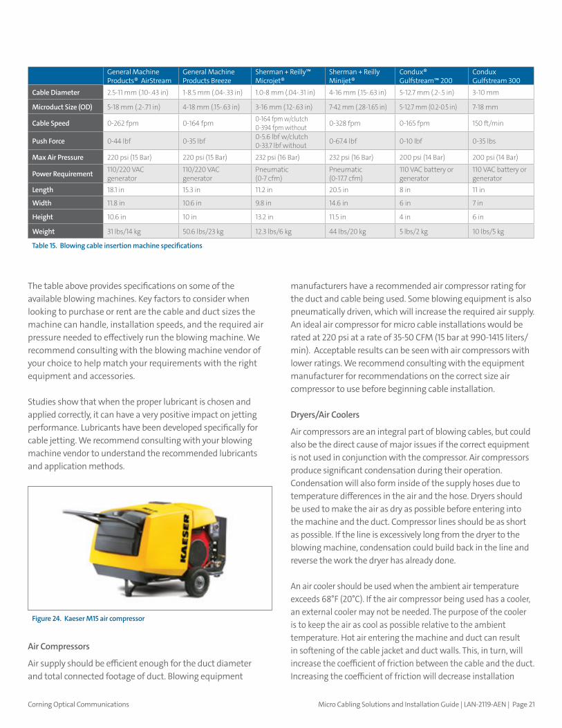
The table above provides specifications on some of the available blowing machines. Key factors to consider when looking to purchase or rent are the cable and duct sizes the machine can handle, installation speeds, and the required air pressure needed to effectively run the blowing machine. We recommend consulting with the blowing machine vendor of your choice to help match your requirements with the right equipment and accessories.
Studies show that when the proper lubricant is chosen and applied correctly, it can have a very positive impact on jetting performance. Lubricants have been developed specifically for cable jetting. We recommend consulting with your blowing machine vendor to understand the recommended lubricants and application methods.
Air Compressors
Air supply should be efficient enough for the duct diameter and total connected footage of duct. Blowing equipment
manufacturers have a recommended air compressor rating for the duct and cable being used. Some blowing equipment is also pneumatically driven, which will increase the required air supply. An ideal air compressor for micro cable installations would be rated at 220 psi at a rate of 35-50 CFM (15 bar at 990-1415 liters/min). Acceptable results can be seen with air compressors with lower ratings. We recommend consulting with the equipment manufacturer for recommendations on the correct size air compressor to use before beginning cable installation.
Dryers/Air Coolers
Air compressors are an integral part of blowing cables, but could also be the direct cause of major issues if the correct equipment is not used in conjunction with the compressor. Air compressors produce significant condensation during their operation. Condensation will also form inside of the supply hoses due to temperature differences in the air and the hose. Dryers should be used to make the air as dry as possible before entering into the machine and the duct. Compressor lines should be as short as possible. If the line is excessively long from the dryer to the blowing machine, condensation could build back in the line and reverse the work the dryer has already done.
An air cooler should be used when the ambient air temperature exceeds 68°F (20°C). If the air compressor being used has a cooler, an external cooler may not be needed. The purpose of the cooler is to keep the air as cool as possible relative to the ambient temperature. Hot air entering the machine and duct can result in softening of the cable jacket and duct walls. This, in turn, will increase the coefficient of friction between the cable and the duct. Increasing the coefficient of friction will decrease installation
General Machine Products® AirStream
General Machine Products Breeze
Sherman + Reilly™ Microjet®
Sherman + Reilly Minijet®
Condux® Gulfstream™ 200
Condux Gulfstream 300
Cable Diameter 2.5-11 mm (.10-.43 in) 1-8.5 mm (.04-.33 in) 1.0-8 mm (.04-.31 in) 4-16 mm (.15-.63 in) 5-12.7 mm (.2-.5 in) 3-10 mm
Microduct Size (OD) 5-18 mm (.2-.71 in) 4-18 mm (.15-.63 in) 3-16 mm (.12-.63 in) 7-42 mm (.28-1.65 in) 5-12.7 mm (0.2-0.5 in) 7-18 mm
Cable Speed 0-262 fpm 0-164 fpm 0-164 fpm w/clutch 0-394 fpm without 0-328 fpm 0-165 fpm 150 ft/min
Push Force 0-44 lbf 0-35 lbf 0-5.6 lbf w/clutch0-33.7 lbf without 0-67.4 lbf 0-10 lbf 0-35 lbs
Max Air Pressure 220 psi (15 Bar) 220 psi (15 Bar) 232 psi (16 Bar) 232 psi (16 Bar) 200 psi (14 Bar) 200 psi (14 Bar)
Power Requirement 110/220 VAC generator
110/220 VAC generator
Pneumatic(0-7 cfm)
Pneumatic(0-17.7 cfm)
110 VAC battery or generator
110 VAC battery or generator
Length 18.1 in 15.3 in 11.2 in 20.5 in 8 in 11 in
Width 11.8 in 10.6 in 9.8 in 14.6 in 6 in 7 in
Height 10.6 in 10 in 13.2 in 11.5 in 4 in 6 in
Weight 31 lbs/14 kg 50.6 lbs/23 kg 12.3 lbs/6 kg 44 lbs/20 kg 5 lbs/2 kg 10 lbs/5 kg
Table 15. Blowing cable insertion machine specifications
Figure 24. Kaeser M15 air compressor

Corning Optical Communications Micro Cabling Solutions and Installation Guide | LAN-2119-AEN | Page 22
speeds and result in shorter installed lengths. As temperature builds in the duct, the duct will become softer and weaker, and the risk of a duct blowout will greatly increase. Air coolers are often driven by the air compressor, so be sure the size of the compressor can accommodate the added load from the cooler.
Payoff System
A payoff system needs to be utilized while deploying micro cables using any blowing equipment. The cable should never be fed across the side of the reel flange. This will cause twisting to occur and could cause damage to the cable. The cable should be assisted coming off the reel during installation. This will require workers to spin the reel while the cable is being installed. Keeping slack in the cable by spinning the reel allows the machines to only push the cable in and not have to overcome the rolling resistance of the payoff, which could decrease push force. A basic reel stand can be used for a micro cable payoff system.
Unique Installation Methods
Micro cables enable a number of innovative deployment techniques that allow fiber to be deployed in previously prohibitive environments and help network operators avoid the high costs associated with digging and placing a new conduit system.
The three methods we will discuss in this guide are:
1. Microduct overrides
2. Micro trenching
3. Cable core extraction
Duct Space Reutilization
Duct space reutilization involves adding capacity to an existing duct where cable is already installed. Common practice is to overlay a new loose tube cable into an existing duct by rodding it either by hand or with a rodding machine. This process can be labor intensive and time consuming. Additionally, rodding can be risky depending on the size of the duct, the number of cables already installed in it, the condition of these cables, and the condition of the duct. The risk is that you could damage the new cable being installed and the cables already installed in the duct during the process. An additional risk is that each new cable you install in a duct will make the next installation of a cable more difficult.
Figure 25. Cable reel stand
Figure 26. Congested duct

Corning Optical Communications Micro Cabling Solutions and Installation Guide | LAN-2119-AEN | Page 23
An alternative method is to blow one or more loose microducts into the existing conduit. Once the microduct installation is complete, you can then install a micro cable with the fiber count of your choosing. The advantage is that the chance of damaging the existing cables in the duct by blowing in a microduct is greatly reduced and the risk of damaging the new cable to be installed is eliminated. The second advantage is that if you install more than one microduct in an existing duct, you have an easy and available upgrade path for the future. It is important to remember that when over-riding an existing duct, all the additional microducts should be installed at the same time.
Microtrenching
Microtrenching is a much less invasive and disruptive technique for trenching in a duct system. Typical open trenching requires digging up a cable pathway, placing the duct, and then backfilling the trench. In an environment such as a city installation, trenching can be very expensive and very slow, as traffic needs to be rerouted and time to access the site can be limited.
With microtrenching, a slot is cut into the earth or asphalt using an earth saw, and a specially designed vertical microduct bundle is inserted into the narrow channel.
The benefits of this method include:
• Significant reduction in installation cost
• Significant reduction in installation time, up to 80 percent faster than traditional open trenching
• Minimal disruption to the surrounding environment
In many cases without microtrenching as an option, some cable installation projects would be impossible due to access issues. However, microtrenching is not always permitted by local regulatory bodies. We recommend contacting your local permitting agency before planning a microtrenching installation.
Steps in Microtrenching Cable
Step 2:Placing microduct in trench
Step 3: Sealing trench with bitumen or other acceptable sealing material
Step 1:Digging the micro trench
Figure 27. Before and after of an existing duct with a cable installed and two new microducts installed
Figure 28. Microtrenching method
Before After

Corning Optical Communications Micro Cabling Solutions and Installation Guide | LAN-2119-AEN | Page 24
Cable Core Extraction
In this scenario, a high-pressure lubricant allows the extraction of the copper core of a legacy coaxial cable. Once the core has been extracted, the outer jacket remains in place and acts as a “makeshift” microduct ready for a micro cable to be installed. This technique is particularly attractive to operators because they benefit from significantly greater capacity (through the switch to fiber) as well as avoiding the expensive costs involved in deploying new infrastructure through reutilization of their legacy infrastructure.
The MSO system operator can benefit from increased bandwidth and avoid expensive deployment costs. However, this deployment method is directly impacted by the quality of the existing coaxial cable plant. Care must also be taken to make sure the correct fill ratio is maintained when matching the right micro cable with the existing coax cable plant.
More information on cable core extraction is available from Deep Fiber Solutions, a leader in the technology, here.
Cable Preparation Tools
Prepping micro cables for splicing or connectorization is similar to the typical procedures for standard loose tube cables. However, it is important to make sure you have the correct tool sizes to work with micro cables. It is always important to consult the manufacturer’s recommended procedures before working with any cable. You should also use the correct tool by part number to avoid damaging the cable or fibers. Although some tools look identical, they are often different enough in specification that an incorrect tool could damage a cable by making too deep of a cut.
Figure 29. Steps of cable core extraction
Figure 30. Typical tools used in accessing a cable

Corning Optical Communications Micro Cabling Solutions and Installation Guide | LAN-2119-AEN | Page 25
What to Look for in a Contractor
Micro cables and microducts are well-established in some markets. Europe, for example, has been using micro cables for more than 15 years. In much of the world, however, micro cables are a relatively new solution. Should you decide that this might be the right solution for your application, it is important to ensure you have the right installation partner in place. Corning recommends working with contractors and installers that are familiar with micro cables and the associated installation practices. Our Network of Preferred Installers (NPI) program includes members that are up to date on the latest product innovations, perform quality work, and have the expertise to ensure a successful installation.
When looking for a contractor, these questions should be asked up front:
• Do they have a relationship with micro cable manufacturers and understand how to use the product?
• Do they have experience in blowing in micro cables?
• Do they have all of the appropriate equipment for the micro cable and microduct system installation available?
• How do they proof a microduct network?
• If you are planning on using MiniXtend HD cable with Corning® SMF-28® 200 fiber, do they have the correct fusion splicers set up?
• How do they warranty their work?
The following table specifies the correct tools to use on both MiniXtend® and MiniXtend HD cables.
Material MiniXtend® Cable with Binderless* FastAccess® Technology 12 fibers/tube 1.4 mm OD MiniXtend HD 24 fibers/tube 1.7 mm OD
Part Number xxxEM4-T3122A20 xxxZH4-Y3140A20
Standard Recommended Procedure 004-197 004-221
Tube cutter Ripley/Miller 721, hole 1.0 mmCorning Fiber Tube Scorer (02-046470-001)
Ripley/Miller 721, hole 1.3 mmCorning Fiber Tube Scorer (02-046470-001)
Tube shaver Ripley MSAT Micro (Nr. 81460)Corning: OFAT-003MXA tool (02-040921-001)
Ripley MSAT Micro (Nr. 81460)Corning: OFAT-003Corning mid-span splitter (02-040919-001)
Tube shaver adapter MSAT micro insert, 1.4 mm (Nr. 81514) MSAT micro insert, 1.7 mm (Nr. 81517)
Other common tools END ACCESS• Vinyl electrical tape • Rule or tape measure • Ideal® tool 45-165 (black plastic housing)• Corning MXA Tool (02-040921-001) • Small screwdriver • Scissors • Fiber cleaning materials
MID-SPAN ACCESS• Corning MXA Tool (02-040921-001)• Permanent marking pen• Seam ripper (100304-01) • MSAT micro• Corning mid-span splitter (02-040919-001)
Same as MiniXtend
** 288 F cable, use Ideal® tool 45-164 (large blue housing )
Table 16.

Corning Optical Communications Micro Cabling Solutions and Installation Guide | LAN-2119-AEN | Page 26
Quick Links to Available Resources
Corning offers many resources to aid in the design and construction of your micro cable/microduct system.
For more information on all Corning products, visit our catalog.
For information on MiniXtend® and MiniXtend HD micro cables, read more product information.
For information on Corning closures, click here.
For information on Corning hardware, click here.
For more detailed technical information:
Microcable Installation
Microduct Cable Air-Assisted Installation Considerations
Corning Closures and Micro Cable Compatibility
Air-Assisted Cable Installation Techniques
Where to Buy?
Contact our Customer Care Team for any Other Questions
Our Engineering Services organization is there to help you every step of the way, from network design to implementation. We offer many services, including some at no cost to our customers.
These services include:
• Network design and site survey
• On-site technical assistance
• Splicing, termination, and testing
• Troubleshooting and restoration
Click here for more information on our Engineering Services offerings.
For information, call (800) 743-2671 (U.S. & Canada), or (828) 901-5000 (International), and ask for Field Engineering.
Figure 31.

Corning Optical Communications Micro Cabling Solutions and Installation Guide | LAN-2119-AEN | Page 27
Glossary Duct – A tube or pipe designed to protect fiber cables which are installed inside the duct.
Microduct – A tube or pipe designed to protect fiber cables which is installed inside the duct. These micro ducts can be installed directly or inside a larger duct to create multiple pathways. Microducts are typically identified as “X/Y” where X = outer diameter, Y = inner diameter or wall thickness = (X-Y)/2
Micro cable – Miniaturized stranded loose tube (LT) cables designed for cable jetting or blowing installations.
Loose tube (LT), stranded – Type of cable design whereby coated fibers are encased in buffer tubes to offer excellent fiber protection and segregation.
Central tube (CT) – Type of cable design whereby coated fibers are encased in a single buffer tube with strength members placed 180 degrees apart under the cable jacket.
ConversionsAir pressure - 1PSI = 0.7 Bar
Volume of air passing through a duct per minute – 1 cubic feet per minute (CFM) = 0.28 liter/mi

Corning Optical Communications LLC • PO Box 489 • Hickory, NC 28603-0489 USACorning Optical Communications reserves the right to improve, enhance, and modify the features and specifications of Corning Optical Communications products without prior notification. A complete listing of the trademarks of Corning Optical Communications is available at www.corning.com/opcomm/trademarks. All other trademarks are the properties of their respective owners. Corning Optical Communications is ISO 9001 certified. © 2017 Corning Optical Communications. All rights reserved. LAN-2119-AEN / July 2017