COMPOSIZIONE ARCHITETTONICA TECNOLOGIE INNOVATIVE PER … · COMPOSIZIONE ARCHITETTONICA &...
100
Anno Accademico 2009-2010 Laurea Specialistica in Ingegneria (C.C.S. Edile) COMPOSIZIONE ARCHITETTONICA & TECNOLOGIE INNOVATIVE PER L’EDILIZIA Prof. Arch. Attilio Pizzigoni Architettura delle strutture reciproche. Lezione 13 ottobre 2009
Transcript of COMPOSIZIONE ARCHITETTONICA TECNOLOGIE INNOVATIVE PER … · COMPOSIZIONE ARCHITETTONICA &...

Anno Accademico 2009-2010Laurea Specialistica in Ingegneria (C.C.S. Edile)
COMPOSIZIONE ARCHITETTONICA&TECNOLOGIE INNOVATIVE PER L’EDILIZIA
Prof. Arch. Attilio Pizzigoni
Architettura delle strutture reciproche.
Lezione 13 ottobre 2009

Good afternoon, everyone, I would like to give my particular thanks to Professor Brian Smith the Chairman of this section and others friends I see here.My name is Attilio Pizzigoni, I’m an architect, as well as a lecturer (lec.iu.rer) at the University of Bergamo School of Engineering.
2
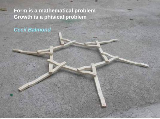
Form is a mathematical problemGrowth is a phisical problem
Cecil Balmond
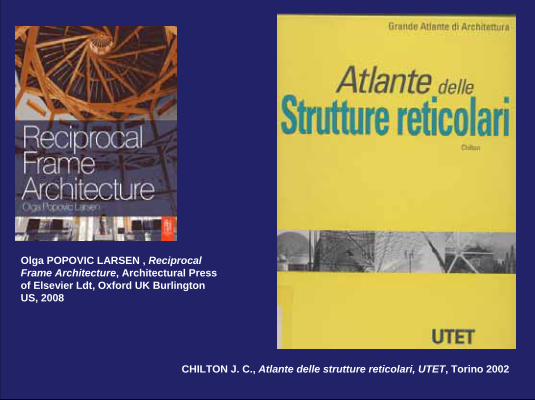
Olga POPOVIC LARSEN , Reciprocal Frame Architecture, Architectural Press of Elsevier Ldt, Oxford UK Burlington US, 2008
CHILTON J. C., Atlante delle strutture reticolari, UTET, Torino 2002
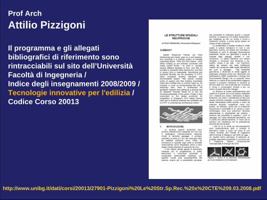
http://www.unibg.it/dati/corsi/20013/27901-Pizzigoni%20Le%20Str.Sp.Rec.%20x%20CTE%209.03.2008.pdf
Prof ArchAttilio Pizzigoni
Il programma e gli allegatibibliografici di riferimento sonorintracciabili sul sito dell’UniversitàFacoltà di Ingegneria /Indice degli insegnamenti 2008/2009 /Tecnologie innovative per l'edilizia /Codice Corso 20013
Le strutture spaziali reciproche
riferimenti storici
historical references
6
7
STRUTTURE SPAZIALI RECIPROCHE
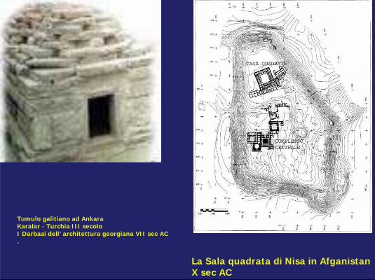
Tumulo galitiano ad AnkaraKaralar - Turchia III secoloI Darbasi dell’ architettura georgiana VII sec AC.
La Sala quadrata di Nisa in Afganistan X sec AC
Villard de HonnecouCostruttore della Cattedrale di Rheim
(autoritrattco
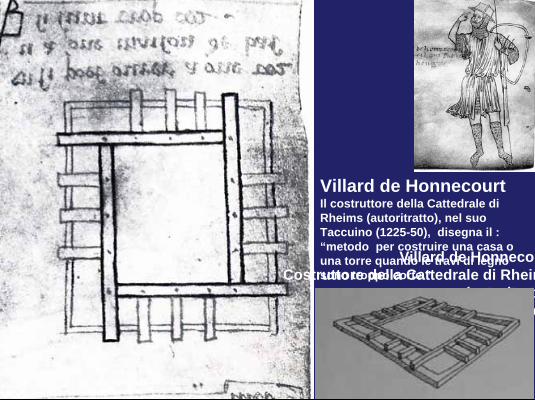
Villard de HonnecourtIl costruttore della Cattedrale di Rheims (autoritratto), nel suo Taccuino (1225-50), disegna il : “metodo per costruire una casa o una torre quando le travi di legno sono troppo corte.”
On the right you see the very famous (fei.mous) sketch by Villard de Honnecourt: and the self-portrait of this medieval architect that worked (workt) in France at Rheims on the construction of the gothic Cathedraland that, in thirteenth century, describes (de.scraib) this building method in his “notebook” (1225-1250),
presenting it as the method to “construct a house or a tower when the wooden beams are too short”
8
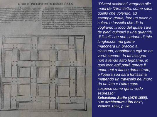
“Diversi accidenti vengono allemani de l’Architetto, come sariaquello che volendo, ad esempio gratia, fare un palco o solare o tassello che dir lo vogliamo ,il loco del quale saràde piedi quindici e una quantitàdi listelli che non sariano di tale lunghezza, ma glienemancherà un braccio a ciascuno, nondimeno egli se ne vorrà servire. In tal bisognonon avendo altro legname, in quel loco egli potrà tenere ilmodo qui a fianco domostrato, e l’opera sua sarà fortissima, mettendo un travicello nel muroda un lato e l’altro capo suspeso come qui si vedeespresso”Sebastiano Serlio (1475-1555), “De Architettura Libri Sex”, Venezia 1663, p. 28
Sebastiano Serlio, from “De Architectura Libri Sex”This one illustrated here is an extremely well known drawing (drou.win), showing the technique of “short beams”.How you can see, their use stands out as being a true and genuine (gen.niu.wain) “handbook solution” in the manual (ma.niu.al) of architecture of Sebastiano Serlio (1475-1554)
“The methods available to an architect for building a ceiling are various; for example, a ceiling of 15 feet, when only short beams of 14 feet are available. Thus not having other wood than that, one would be able to keep to the method demonstrated here. The work will be
t l h d fi i h t b i t th ll9
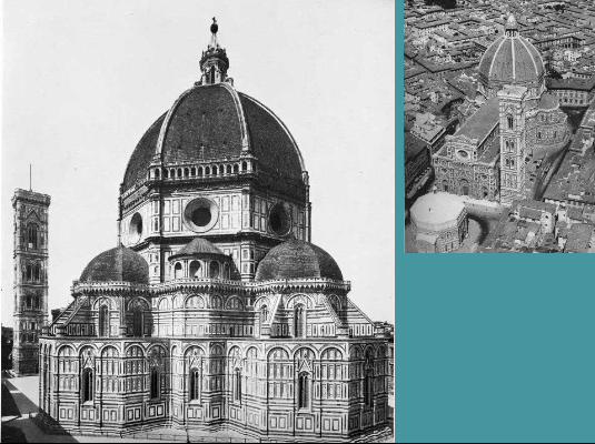
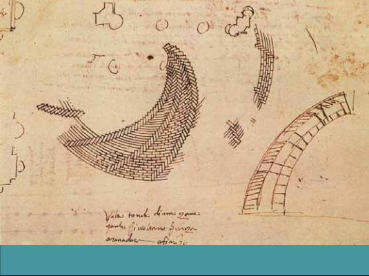
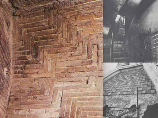
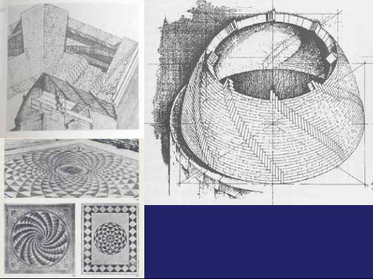
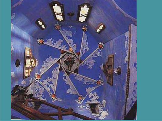
I studied some years ago the work of Brunelleschi (I wrot a book edited by Zanichelli in Italy and Artemis Verlag in Germany) and I noticed that a principle of structural reciprocity is also present in the static design of the dome of the Santa Maria del Fiore Cathedral by Filippo Brunelleschi in Florence. In particular, in the spirals (spai.ral) of bricks laying in form “like a herringbone” as pointed out by Giuliano Da Sangallo in contemporary designs.
13
This principle is formed (fo.md) by the skeleton of bricks positioned in order to reciprocally discharge the loads (LOds) onto the spirals as indicated (in.dic.ei.tid) in the drawing by SangalloThis Brunelleschian or “herringbone” procedure (pro.si.diur) permits the load of a vault to be discharged upon the inferior spirals; thus (thas) creating a spatial (spei.scial) system that is very similar to a “reciprocal structure”.
Recently (rii.cently) this question was also emphasised (em.fa.saized) by Salvatore Di Pasquale in his studies about Brunelleschi ( L’arte di costruire – Art of building, 1996)
14
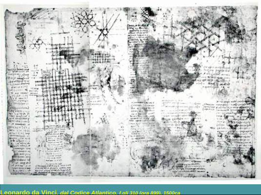
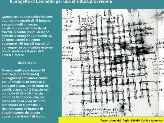
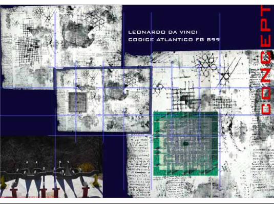
Leonardo da Vinci, dal Codice Atlantico, f.gli 310 (ora 899), 1500ca
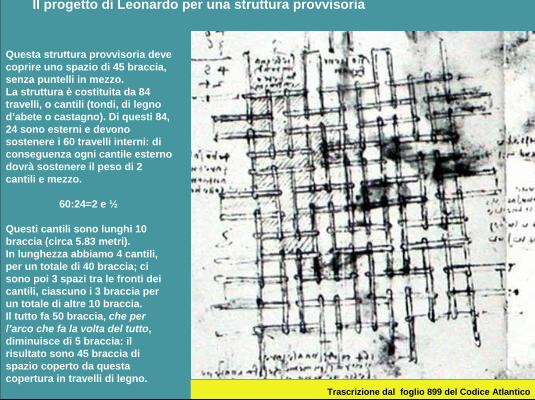
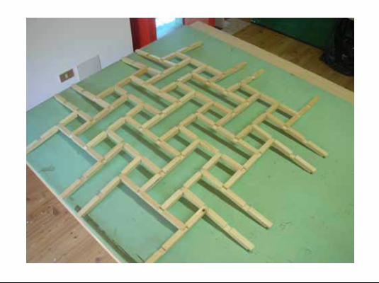
Questa struttura provvisoria deve coprire uno spazio di 45 braccia, senza puntelli in mezzo.La struttura è costituita da 84 travelli, o cantili (tondi, di legno d’abete o castagno). Di questi 84, 24 sono esterni e devono sostenere i 60 travelli interni: di conseguenza ogni cantile esterno dovrà sostenere il peso di 2 cantili e mezzo.
60:24=2 e ½
Questi cantili sono lunghi 10 braccia (circa 5.83 metri).In lunghezza abbiamo 4 cantili, per un totale di 40 braccia; ci sono poi 3 spazi tra le fronti dei cantili, ciascuno i 3 braccia per un totale di altre 10 braccia.Il tutto fa 50 braccia, che per l’arco che fa la volta del tutto, diminuisce di 5 braccia: il risultato sono 45 braccia di spazio coperto da questa copertura in travelli di legno.
Il progetto di Leonardo per una struttura provvisoria
Trascrizione dal foglio 899 del Codice Atlantico
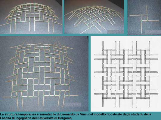
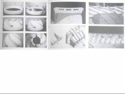
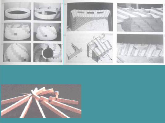
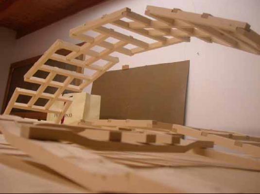
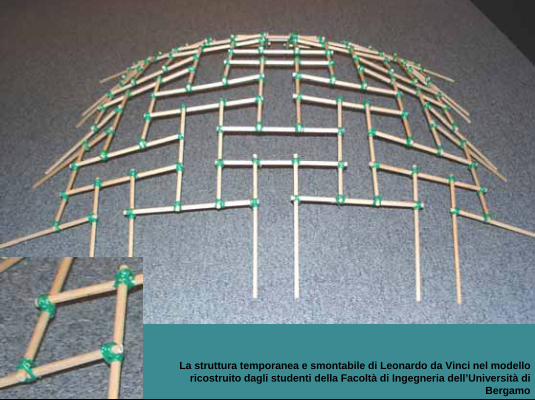
La struttura temporanea e smontabile di Leonardo da Vinci nel modello ricostruito dagli studenti della Facoltà di Ingegneria dell’Università di Bergamo
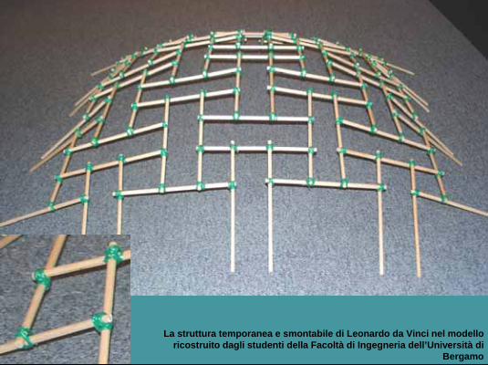
La struttura temporanea e smontabile di Leonardo da Vinci nel modello ricostruito dagli studenti della Facoltà di Ingegneria dell’Università di
Bergamo
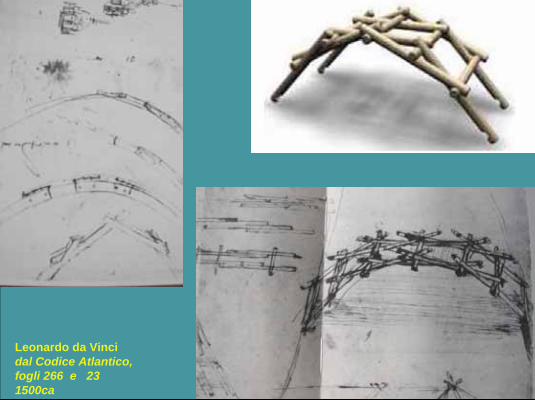
Leonardo da Vincidal Codice Atlantico, fogli 266 e 23 1500ca
21
STRUTTURE SPAZIALI RECIPROCHE
.
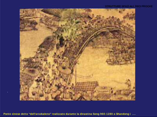
Ponte cinese detto “dell’arcobaleno” realizzato durante la dinastina Song 960-1280 a Shandong i ….
L’uso di questa tecnologia costruttiva viene applicato in divesi casi nella realizzazione dei templi dei monaci buddisto Chogen (1121 1206)
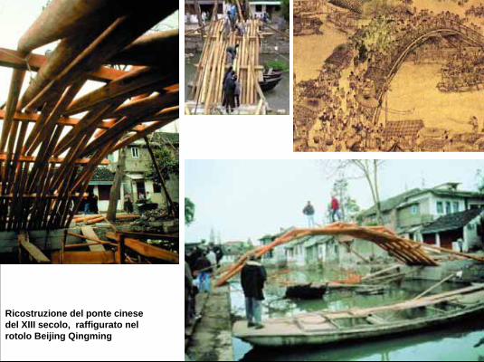
Ricostruzione del ponte cinesedel XIII secolo, raffigurato nel rotolo Beijing Qingming
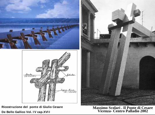
Massimo Scolari . Il Ponte di CesareVicenza- Centro Palladio 2002
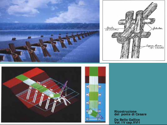
Ricostruzione del ponte di Giulio Cesare
De Bello Gallico Vol. IV cap.XVII
It is probable that this short beam construction technique was also well known during the Imperial (Im.pii.rial) Roman period (pii.riod). It was most likely for the construction of temporary works like the bridge over the Rhine (Rhai.ne) as cited (sit.d) by Vitruvio and described by Julius Caesar in his book “Commentary (COM.men.ta.ry) on the Gallic War” .Some years ago was studied in a full-scale reconstruction; drawing, plans and models were produced (pro.diu.st) by Massimo Scolari with F.Laner and exhibited (ex.HI.bited) in a recent (rii.cent) show in Vicenza at the Centro Palladio.
23
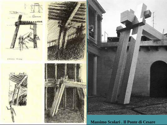
Massimo Scolari . Il Ponte di Cesare
Ricostruzione del ponte di Cesare
De Bello Gallico Vol. IV cap.XVII
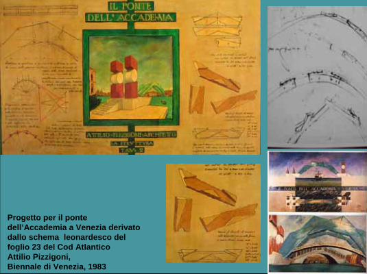
Progetto per il ponte dell’Accademia a Venezia derivato dallo schema leonardesco del foglio 23 del Cod AtlanticoAttilio Pizzigoni,Biennale di Venezia, 1983
fine
fine

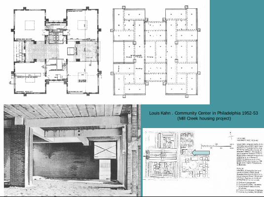
Louis Kahn . Community Center in Philadelphia 1952-53(Mill Creek housing project)
These four square rooms of the Community (comm.iu.nity) Centre in Philadelphia, designed in 1952 by Louis Kahn, are often cited, and it is one of the very few examples of reciprocal structure by concrete in contemporary architecture.
34
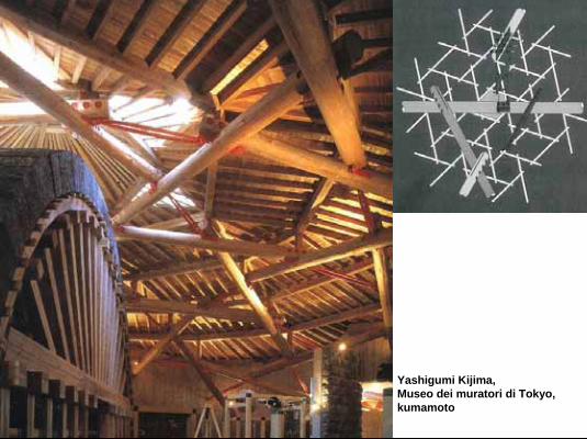
Yashigumi Kijima,Museo dei muratori di Tokyo, kumamoto
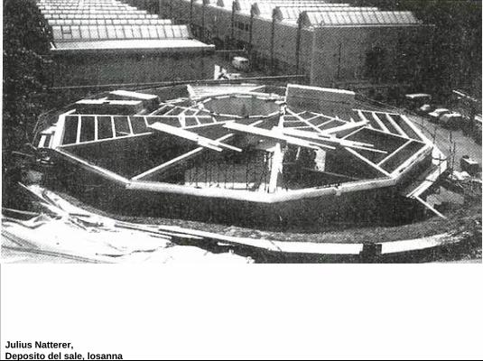
Julius Natterer,Deposito del sale, losanna
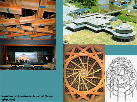
Kazuhiro ishii, teatro dei burattini, Seiwa(giappone)
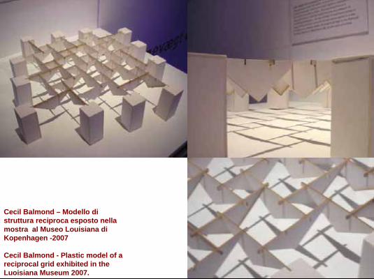
Cecil Balmond – Modello di struttura reciproca esposto nella mostra al Museo Louisiana di Kopenhagen -2007.Cecil Balmond - Plastic model of a reciprocal grid exhibited in the Luoisiana Museum 2007.
But in recent years, the choice to use these structures seems to occur ever more frequently (frii.quentli) in international architecture …
And this image is how Balmon presented one potential use of reciprocal grids with a model of a pavilion that was displayed at the Louisiana Museum exhibition in 2007 (tu.tausand.and.seven).
38
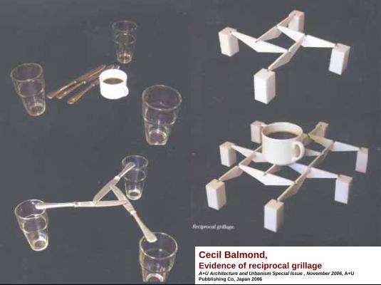
Cecil Balmond, Evidence of reciprocal grillageA+U Architecture and Urbanism Special Issue , November 2006, A+U Pubblishing Co, Japan 2006
This is a very explicit image how Cecil Balmond presented spatially reciprocal grids in a recent publication.
39
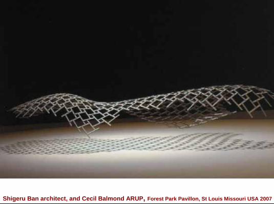
Shigeru Ban architect, and Cecil Balmond ARUP, Forest Park Pavillon, St Louis Missouri USA 2007
Here is a study for the “Forest Park Pavilion, St. Louis Missouri USA 2004-2007” ;another project by Cecil Balmond, in collaboration with Sigheru Bahn architect.
40
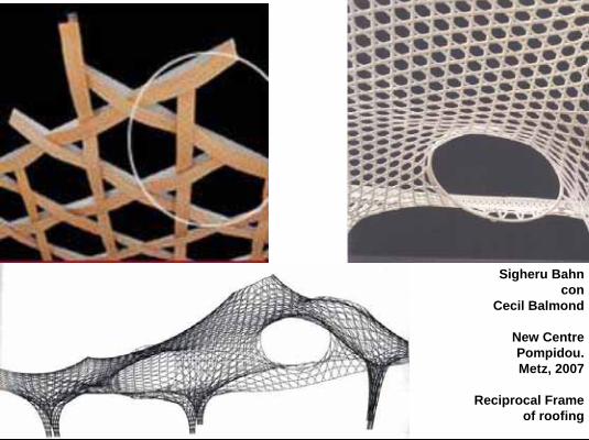
Sigheru Bahncon
Cecil Balmond
New CentrePompidou.Metz, 2007
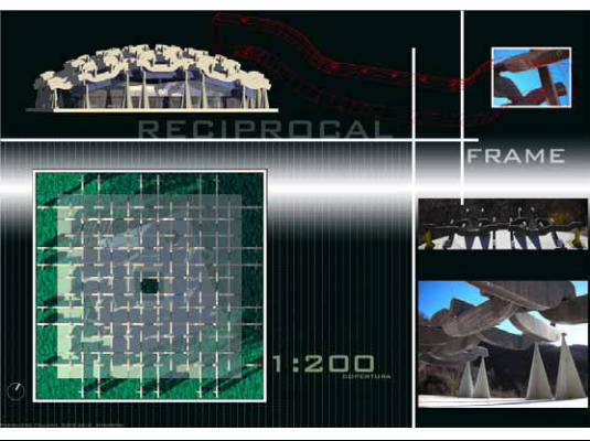
Reciprocal Frame of roofing
Sigheru Bahn with Cecil Balmond,Studies for the New Guggenheim Museum. Metz, 2007Reciprocal frame roofing
41
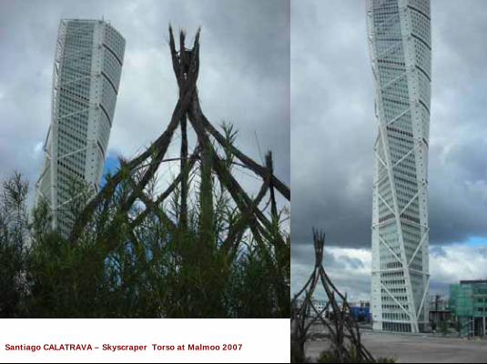
Santiago CALATRAVA – Skyscraper Torso at Malmoo 2007
You can see the structural analogy of two works: an earlier Scandinavian hut (hat), and the Calatrava’s skyscraper (sky.screiper) “Torso”in Malmoo, also in comparison ( com.par.is.on) to the brunelleschian dome.
42
Geometrical research design and
experimental test modelsassembled by
students of the University of Bergamo
I will now show you some models and prototypes built together with the students..These teaching studies began from geometrical studies of a modular (mo.diu.la) model that is flexible and demountable
43
Moduli compositivi a griglia ortogonale con elemento standardizzato

fine
fine
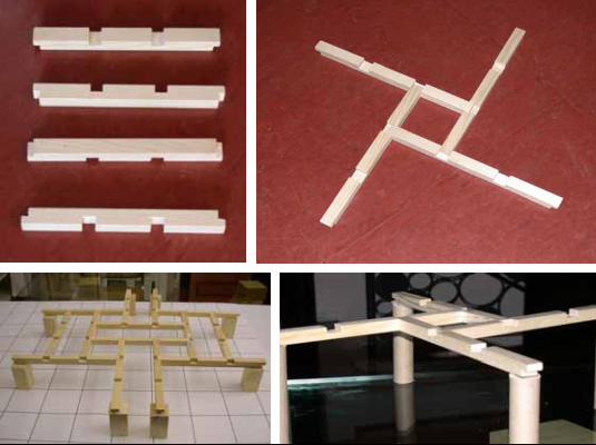
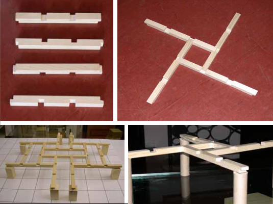
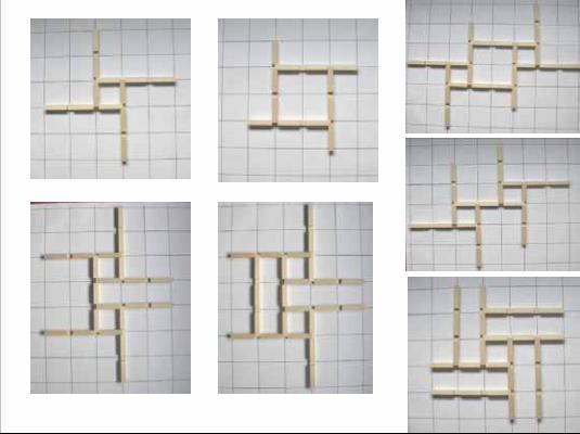
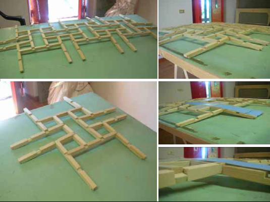
Of course we began the studies using Serlio’s beams, trying out their modular flexibility and ….. arranging the beams into various geometries using a single modular element.
62
A single element is able to make different knots (notz) and types of junction .
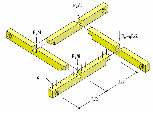
The arrangement of the elements was also studied considering a modular element that is able to form 3, 4, 5, 6 or even (ii.ven) more element junctions.
63
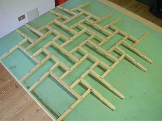
A single element is able to make different knots (notz) and types of junction .
The arrangement of the elements was also studied considering a modular element that is able to form 3, 4, 5, 6 or even (ii.ven) more element junctions.
64
A single element is able to make different knots (notz) and types of junction .
The arrangement of the elements was also studied considering a modular element that is able to form 3, 4, 5, 6 or even (ii.ven) more element junctions.
65
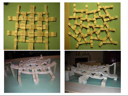
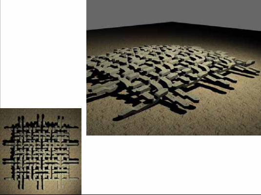
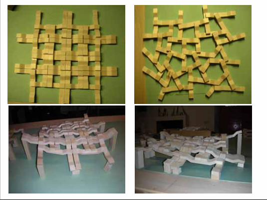
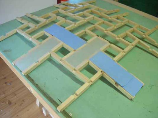
And the flexibility of knots between the elements, their flexibility on a plane and/or in space, permits them to express very different characteristics.
66
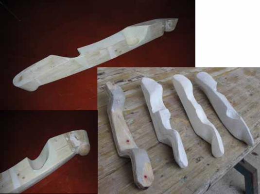
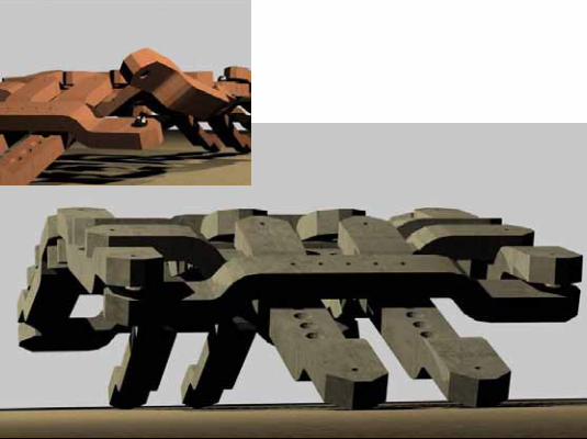
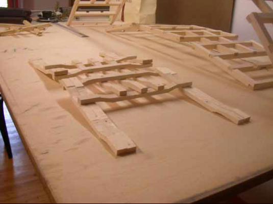
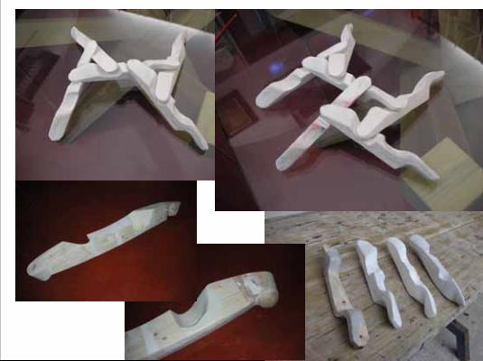
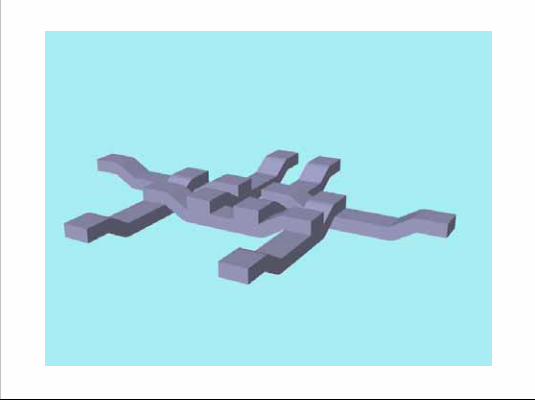
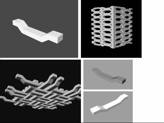
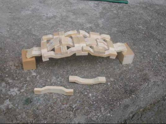
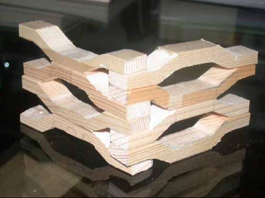
During our trials, a certain interest grew (gru) from the formal research aimed at defining a more “organic” shape for the basic (bei.sic) element.
The geometrical optimization (opti.mai.zation) of the elements ( short beams) was done in order to increase their flexibility and produce “organic”and biomorphic (baio-) shapes, in a similar way to an anatomical joint or to helix (hii.lix) geometry.
67
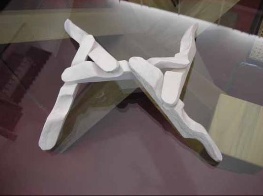
During our trials, a certain interest grew (gru) from the formal research aimed at defining a more “organic” shape for the basic (bei.sic) element.
The geometrical optimization (opti.mai.zation) of the elements ( short beams) was done in order to increase their flexibility and produce “organic”and biomorphic (baio-) shapes, in a similar way to an anatomical joint or to helix (hii.lix) geometry.
68
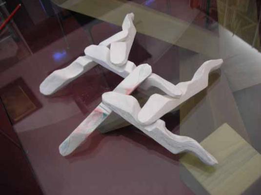
During our trials, a certain interest grew (gru) from the formal research aimed at defining a more “organic” shape for the basic (bei.sic) element.
The geometrical optimization (opti.mai.zation) of the elements ( short beams) was done in order to increase their flexibility and produce “organic”and biomorphic (baio-) shapes, in a similar way to an anatomical joint or to helix (hii.lix) geometry.
69
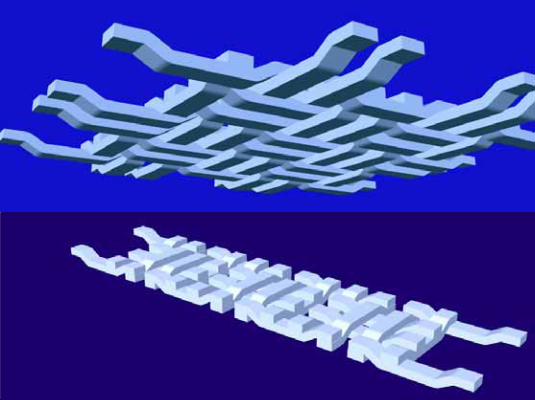
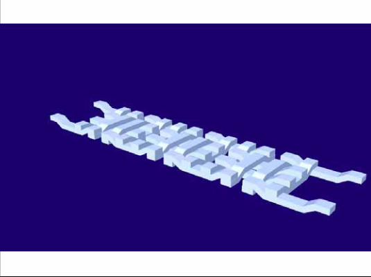
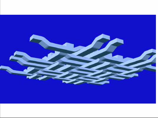
These models are 3D CAD (Three dimensional computer design)
70
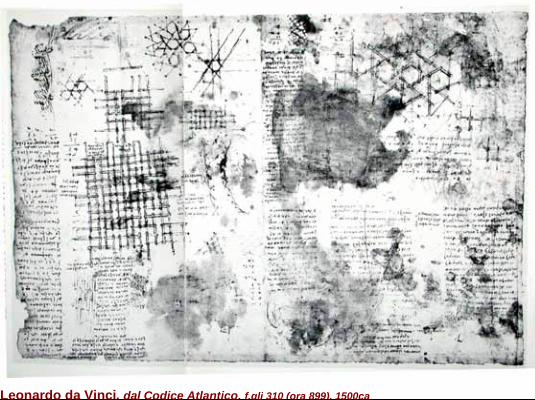
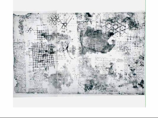
Leonardo da Vinci, dal Codice Atlantico, f.gli 310 (ora 899), 1500ca
This is the key (kii) study by Leonardo, which we have examined (ics.amind) and which gives most useful suggestions and insight on our topic.This famous sheet (number 899 of Leonardo Da Vinci’s Atlantic Code) is the project for a temporary roof of 45 arm spans, built with 84 wooden beams which he calls :“cantili”).(about 20 metres (mii.terz) spanned (spand) by this framework of timbers
71
Questa struttura provvisoria deve coprire uno spazio di 45 braccia, senza puntelli in mezzo.La struttura è costituita da 84 travelli, o cantili (tondi, di legno d’abete o castagno). Di questi 84, 24 sono esterni e devono sostenere i 60 travelli interni: di conseguenza ogni cantile esterno dovrà sostenere il peso di 2 cantili e mezzo.
60:24=2 e ½
Questi cantili sono lunghi 10 braccia (circa 5.83 metri).In lunghezza abbiamo 4 cantili, per un totale di 40 braccia; ci sono poi 3 spazi tra le fronti dei cantili, ciascuno i 3 braccia per un totale di altre 10 braccia.Il tutto fa 50 braccia, che per l’arco che fa la volta del tutto, diminuisce di 5 braccia: il risultato sono 45 braccia di spazio coperto da questa copertura in travelli di legno.
Il progetto di Leonardo per una struttura provvisoria
Trascrizione dal foglio 899 del Codice Atlantico

La struttura temporanea e smontabile di Leonardo da Vinci nel modello ricostruito dagli studenti della Facoltà di Ingegneria dell’Università di Bergamo
La struttura temporanea e smontabile di Leonardo da Vinci nel modello ricostruito dagli studenti della Facoltà di Ingegneria dell’Università di
Bergamo
E C
A
A
CD
A
B
B
C
E
EE B
C
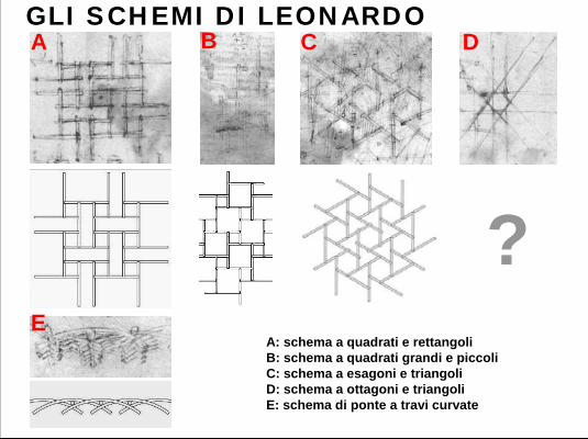
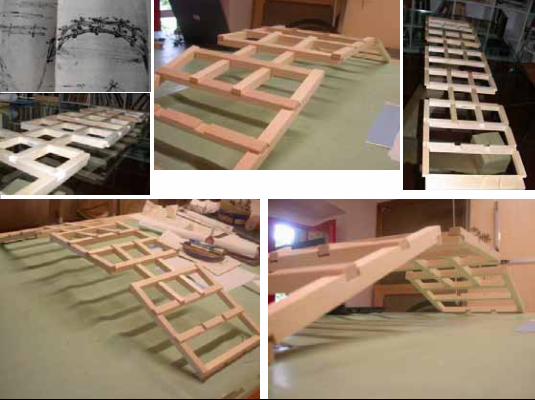
GLI SCHEMI DI LEONARDO
A: schema a quadrati e rettangoliB: schema a quadrati grandi e piccoliC: schema a esagoni e triangoliD: schema a ottagoni e triangoliE: schema di ponte a travi curvate
?
BA C D
E
Adjusting the thickness of the joint gives the grid a three-dimensional form, forming a geodetical dome .
77
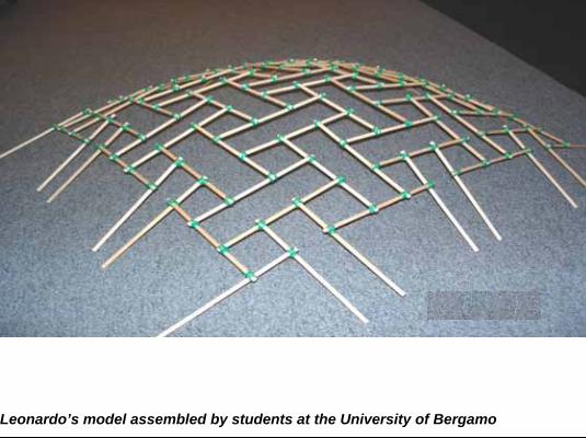
Leonardo’s model assembled by students at the University of Bergamo
This is the 3D phisic model of Leonardo’s design
reconstructed by the students, It clearly demonstrates the geodetic conformation.
78
We wanted also to confirm the real applications of the technologies studied. The idea (ai.dii.a) of the proposed project makes reference to Leonardo’s design in the Atlantic Code.
So this project was submitted to the competition for the construction of the Italian Pavilion \ for the 2010 World Expo in Shanghai.Although it did not gain the successful of a price but only of a recommendation. The competition rules required \ for environmental sustainability that the structure could be dismantled after its temporary use and potentially reused in a different form and for a different function.
Here is the presentation of our project…..
79
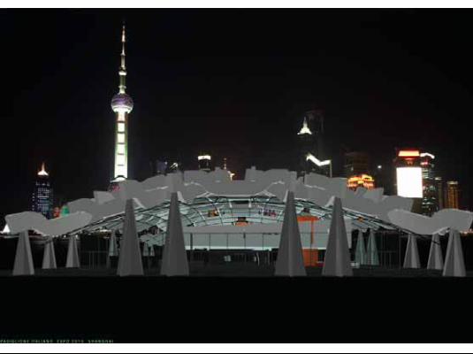
This is a rendering outside elevation
80
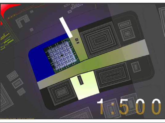
A planimetrical view
81
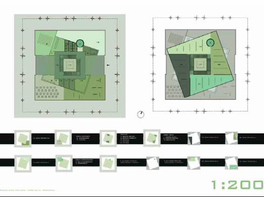
The function layout
82
Leonardo’s design is twenty meters spanned. Our project is forty
83
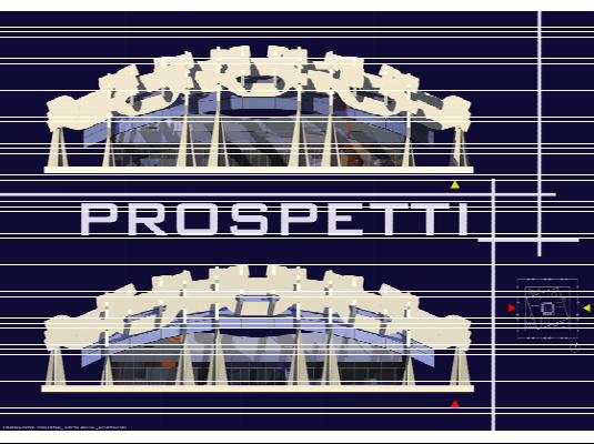
Elevation plans
84
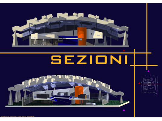
sections
85
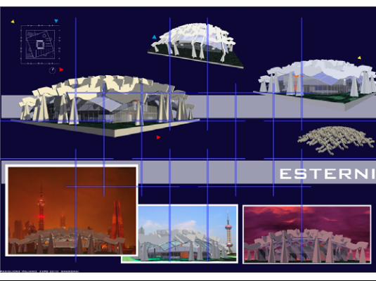
Outside view
86
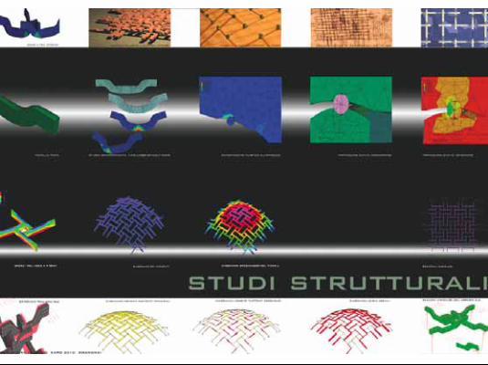
Some structural models
87
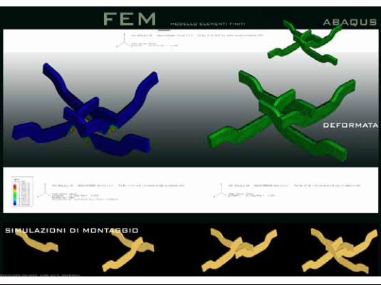
Simulated mounting
88
Here is the presentation of our project…..
89
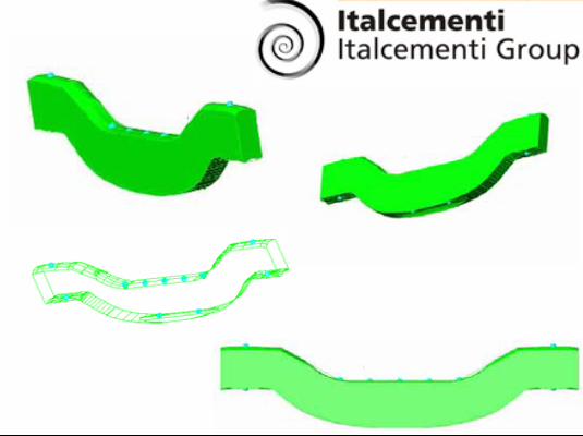
A renowned company from Bergamo, a world leader in the production of cement, also looked at this project, gave us the possibility to make and test some prototypes of demountable elements for the creation of temporary roofs and buildings.
90
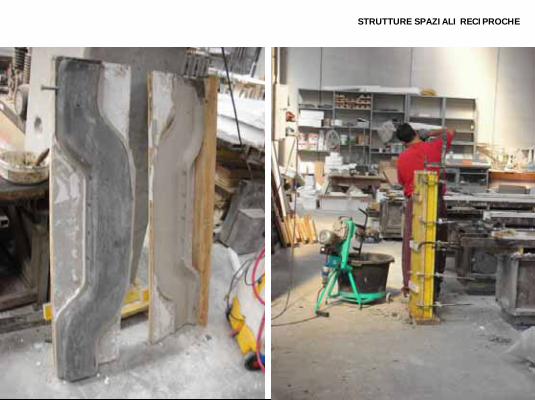
STRUTTURE SPAZIALI RECIPROCHE
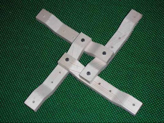
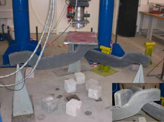
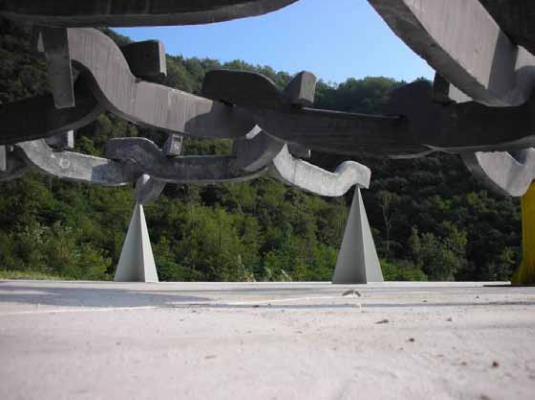
We built the model using a high resistance concrete of reinforced fibre (fei.ber) (HRC).The prototype was of an appropriate dimension and weight (weit) (25 Kilos) such that it could (cud) easily be positioned (poz.i.sciond) during the trials.
91
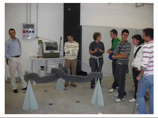
STRUTTURE SPAZIALI RECIPROCHE
The photo is of the students with the laboratory models
92
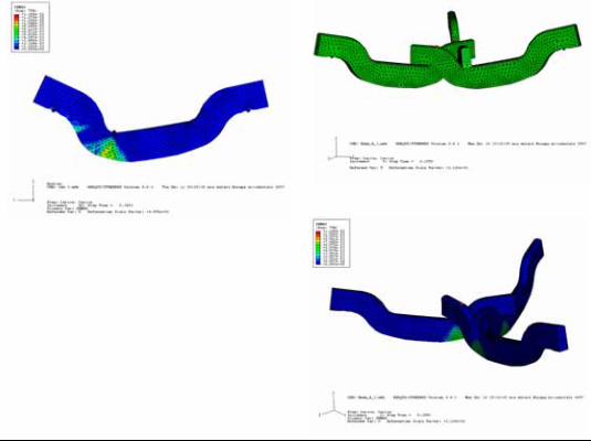
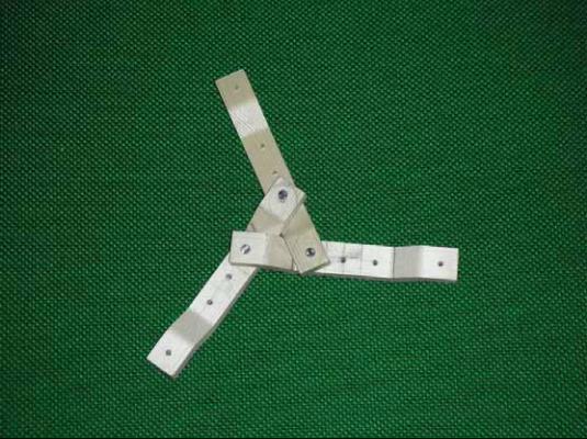
Finished (..t) Elements Model FEM
The theoretical model FEM, Finished Elements Model, of a three element junction, elaborated (i.la.bor.ei.tid) using the computer software ABACUS
93
The fracture (fra.ciur) trials conducted in the laboratories of the University of Bergamo confirmed the results obtained from the static tests carried out on the Finished Elements Model.
94
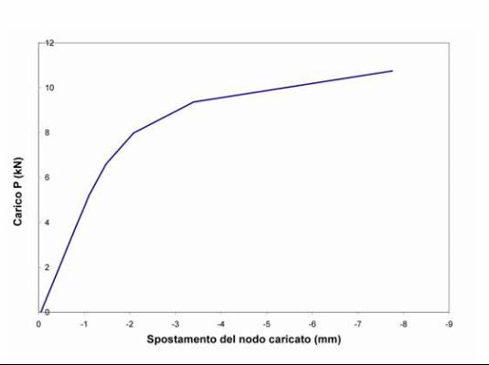
In the graph we see the plastic behaviour of the model in Height Reinforced Fibre Concrete.We found substantial homogeneity (ho.mo.ge.ni.ty) in the results between the physical and theoretical model.
Their agreement with the results of experimental fracture trials, demonstrated the possibility of studying even more complex structures using the classical process of the Science of Building
95
STRUTTURE SPAZIALI RECIPROCHE
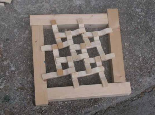
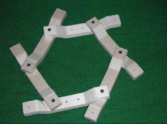
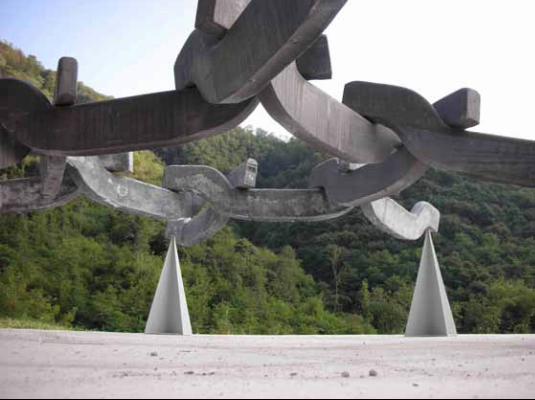
The prototype demonstrated the ease of their assembly and of their dismantling..
96
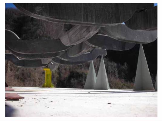
STRUTTURE SPAZIALI RECIPROCHE
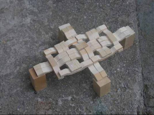
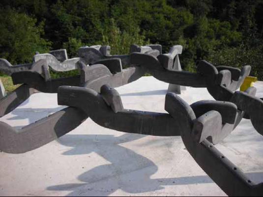
The composition game is without limits. The same elements arranged with a different geometry
97
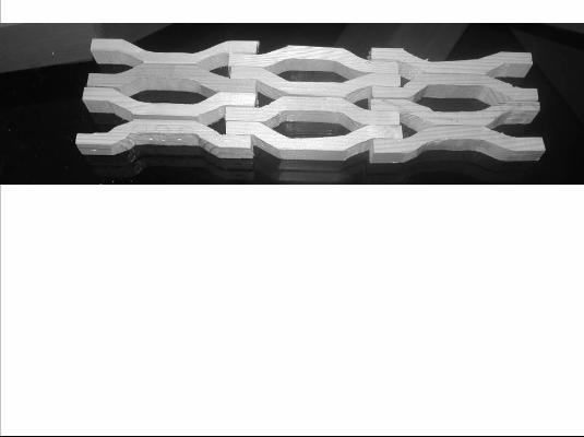
The physical model with prototype beams \assembled into hexagonal schemes (skims) \with three-element junctions
98
The physical model with prototyped beams \ assembled into square schemes (skims) \ with four-element junctions
99
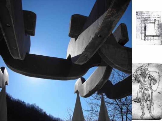
This is my last imageOn the right you see the very famous (fei.mous) sketch by Villard de Honnecourt: and the self-portrait of this medieval architect that worked (workt) in France at Rheims on the construction of the gothic Cathedraland that, in thirteenth century, describes (de.scraib) this building method in his “notebook” (1225-1250),
presenting it as the method to “construct a house or a tower when the wooden beams are too short”
Eight century are past, and you can see, we are small followers of those biggest builder men.
Thank you very much.
100