COMPOSITES 2011 1. American Composites Manufacturers ...€¦ · American Composites Manufacturers...
11
COMPOSITES 2011 1 COMPOSITES 2011 American Composites Manufacturers Association February 2-4, 2011 Ft. Lauderdale, Florida USA The Effect of Nanosilica Matrix Modifi- cation on the Improvement of the Pultrusion Process and Mechanical Properties of Pultruded Epoxy Carbon Fiber Composites by Kristin Thunhorst, Douglas Goetz, Andrew Hine, and Paul Sedgwick 3M Company ABSTRACT A study was undertaken to investigate the effect of nano-scale spherical silica particle inclusion on the pul- trusion process and the mechanical properties of the resulting epoxy-carbon fiber composite pultruded ar- ticles. The trial compared a nanosilica-modified epoxy matrix resin having a loading level of 32.6% by weight with a control resin having no nanosilica. Both bis- phenol-A-based (DGEBA) epoxy resins were cured with a liquid anhydride curative (MTHPA formulated for pul- trusion) at a 0.95 ratio of anhydride equivalents to epoxy equivalents. Pultruded parts with a rectangular cross- section approximately 0.5 inch (1.27 cm) by 0.125 inch (0.318 cm) were produced with standard modulus carbon fiber (12,000 filament tows). In the pultrusion process, a significant reduction (54%) in average pull force was achieved. Carbon fiber volumes up to 68.4 volume % were enabled by the low pull force when the nanosilica was included in the epoxy. Pultruded articles with ele- vated flexural modulus (up to 21,000 ksi (144.8 GPa)) were produced due to the high carbon fiber volume enabled by the inclusion of the nanosilica. The addition of nanosilica provided significant pultrusion process im- provements as well as mechanical property improvements in the peak shear stress (Short Beam Shear Test) and flexural failure stress (3-Point Bend Test) in pultruded articles made with the nanosilica- modified epoxy resin. 1. INTRODUCTION 1.1 Background The effect of fillers on the pultrusion process and on pultruded composite properties has been studied expe- rimentally and published in the technical literature. Traditional fillers for pultrusion include a variety of clays, such as kaolin clays for corrosion resistance, elec- trical insulation and surface finish, and other fillers such as calcium carbonate as a low cost volume extender and alumina trihydrate for flame or smoke suppression (1). Fillers are commonly included in pultrusion resins to af- fect die compaction, processability, surface finish, fire retardance, electrical properties, and mechanical proper- ties, to reduce adhesion of the resin to the die and to reduce the exotherm experienced in thick pultruded parts. Frequently, the filler type, concentration, and sur- face treatment, if any, have a significant effect on the viscosity of the system and can have a profound effect on pultrusion processability. In many cases, formulated pultrusion resins with higher viscosity produce a greater pull force in the pul- trusion process due to the viscous drag acting between the fibers and the die wall (2). The pull force limits the line speed and fiber volumes that can be achieved. A pultrusion study of kaolin clay filler in glass fiber- reinforced unsaturated polyester resins (UPR) showed increasing pull force as the clay concentration was in- creased from 20 parts per hundred resin (phr) up to 40 phr (3). The study also showed that the increasing con- centration of low-profile additives which prevent shrinkage in the second half of the curing die also re- sulted in increases in pull force for the glass fiber-UPR composite (3). In addition to affecting the processing, fillers also play a role in the flexural strength and short beam shear strength of pultruded composites. In the kaolin clay – UPR pultrusion study mentioned previously, the shear strength of the pultruded composite decreased approx- imately 10% as the filler concentration was increased from 20 phr to 40 phr. In the same study, no statistically significant effect was shown on the flexural strength as the clay content was manipulated over the same concen- tration range (3). In a different study of 7 different types of fillers (including kaolin clays) in epoxy resins pul- truded with glass fiber, the sample with the lowest filler loading (5 phr) also showed the lowest short beam shear strength (4). In the epoxy study, the samples that were most highly loaded with filler (20 phr) showed the high- est short-beam shear strength (4). The composite flexural strength in the epoxy-glass composite study de- creased with increasing filler content for the two comparisons reported (4). Recently in the composites industry, new technolo- gy in fillers, and particularly in nanomaterials, have provided attractive property improvements in compari- son to those achieved with more traditional filler
Transcript of COMPOSITES 2011 1. American Composites Manufacturers ...€¦ · American Composites Manufacturers...
COMPOSITES 2011 1
COMPOSITES 2011 American Composites Manufacturers Association February 2-4, 2011 Ft. Lauderdale, Florida USA
The Effect of Nanosilica Matrix Modifi-cation on the Improvement of the
Pultrusion Process and Mechanical Properties of Pultruded Epoxy Carbon
Fiber Composites
by
Kristin Thunhorst, Douglas Goetz,
Andrew Hine, and Paul Sedgwick 3M Company
ABSTRACT
A study was undertaken to investigate the effect of nano-scale spherical silica particle inclusion on the pul-trusion process and the mechanical properties of the resulting epoxy-carbon fiber composite pultruded ar-ticles. The trial compared a nanosilica-modified epoxy matrix resin having a loading level of 32.6% by weight with a control resin having no nanosilica. Both bis-phenol-A-based (DGEBA) epoxy resins were cured with a liquid anhydride curative (MTHPA formulated for pul-trusion) at a 0.95 ratio of anhydride equivalents to epoxy equivalents. Pultruded parts with a rectangular cross-section approximately 0.5 inch (1.27 cm) by 0.125 inch (0.318 cm) were produced with standard modulus carbon fiber (12,000 filament tows). In the pultrusion process, a significant reduction (54%) in average pull force was achieved. Carbon fiber volumes up to 68.4 volume % were enabled by the low pull force when the nanosilica was included in the epoxy. Pultruded articles with ele-vated flexural modulus (up to 21,000 ksi (144.8 GPa)) were produced due to the high carbon fiber volume enabled by the inclusion of the nanosilica. The addition of nanosilica provided significant pultrusion process im-provements as well as mechanical property improvements in the peak shear stress (Short Beam Shear Test) and flexural failure stress (3-Point Bend Test) in pultruded articles made with the nanosilica-modified epoxy resin.
1. INTRODUCTION
1.1 Background
The effect of fillers on the pultrusion process and on pultruded composite properties has been studied expe-rimentally and published in the technical literature. Traditional fillers for pultrusion include a variety of clays, such as kaolin clays for corrosion resistance, elec-trical insulation and surface finish, and other fillers such as calcium carbonate as a low cost volume extender and alumina trihydrate for flame or smoke suppression (1). Fillers are commonly included in pultrusion resins to af-fect die compaction, processability, surface finish, fire retardance, electrical properties, and mechanical proper-ties, to reduce adhesion of the resin to the die and to reduce the exotherm experienced in thick pultruded parts. Frequently, the filler type, concentration, and sur-face treatment, if any, have a significant effect on the viscosity of the system and can have a profound effect on pultrusion processability.
In many cases, formulated pultrusion resins with higher viscosity produce a greater pull force in the pul-trusion process due to the viscous drag acting between the fibers and the die wall (2). The pull force limits the line speed and fiber volumes that can be achieved. A pultrusion study of kaolin clay filler in glass fiber-reinforced unsaturated polyester resins (UPR) showed increasing pull force as the clay concentration was in-creased from 20 parts per hundred resin (phr) up to 40 phr (3). The study also showed that the increasing con-centration of low-profile additives which prevent shrinkage in the second half of the curing die also re-sulted in increases in pull force for the glass fiber-UPR composite (3).
In addition to affecting the processing, fillers also play a role in the flexural strength and short beam shear strength of pultruded composites. In the kaolin clay – UPR pultrusion study mentioned previously, the shear strength of the pultruded composite decreased approx-imately 10% as the filler concentration was increased from 20 phr to 40 phr. In the same study, no statistically significant effect was shown on the flexural strength as the clay content was manipulated over the same concen-tration range (3). In a different study of 7 different types of fillers (including kaolin clays) in epoxy resins pul-truded with glass fiber, the sample with the lowest filler loading (5 phr) also showed the lowest short beam shear strength (4). In the epoxy study, the samples that were most highly loaded with filler (20 phr) showed the high-est short-beam shear strength (4). The composite flexural strength in the epoxy-glass composite study de-creased with increasing filler content for the two comparisons reported (4).
Recently in the composites industry, new technolo-gy in fillers, and particularly in nanomaterials, have provided attractive property improvements in compari-son to those achieved with more traditional filler

COMPOSITES 2011 2
systems. In particular, the nanomaterials are more able to produce uniform concentration and homogeneous re-sin properties in composites than the traditional fillers that can experience filtration by fibers due to their large particle size relative to fiber-fiber spacing. As one ex-ample, polymer - clay nanocomposites were shown to improve thermal stability, fire retardance, barrier proper-ties, flexural modulus strength and toughness. Additionally, recent work on prepreg-appropriate resin systems has shown that the inclusion of nanosilica in neat resin epoxy castings provides increased neat resin modulus and, correspondingly, increased compression strength in the unidirectional composite laminates made from the resin (5).
The current paper is focused on nanomaterial ma-trix modification also, but for composite processing requiring resins with significantly lower viscosity than prepreg resins, specifically resins for pultrusion.
1.2 Current Study and Resins
This paper outlines the unique processing benefits and mechanical property improvements of nano-scale spherical silica-filled resin technology for pultrusion processes and products. This appears to be the first eval-uation of the effects of nanosilica on a pultrusion resin system. Comparisons are offered between composites made using a control resin with no silica nanoparticles, but having a common kaolin clay additive, and a nanosi-lica-modified epoxy containing 32.6 wt% nanosilica (but no clay) in the cured resin. Resins formulated for the current study were used for experiments run on a commercial pultrusion manu-facturing line. Pull force was monitored as the fiber volume fraction of the composite was varied. The mi-crostructure of the cured composites was examined, and key mechanical properties of the composites were com-pared.
For the control sample in the pultrusion experiment, 5.0% by weight of a typical kaolin clay used in pultru-sion was included in a DGEBA-based epoxy in order to represent a typical epoxy pultrusion resin. No clay was added to the nanosilica-modified epoxy resin. The na-nosilica, which is less than 100 nm in diameter, had been modified to be compatible with the epoxy resin. The na-nosilica-modified epoxy resin and the control resin were each cured with the same stoichiometric amount of an MTHPA-based anhydride that had been formulated for pultrusion, resulting in a 0.95 ratio of equivalents of an-hydride to equivalents of epoxy.
2. EXPERIMENTAL
2.1 Resin Sample Preparation
For the control resin sample of the pultrusion expe-riment, 94.9 parts by weight of the MTHPA-based curative (formulated for pultrusion) were blended with
0.10 parts by weight of kaolin clay and 100 parts by weight of the DGEBA-based epoxy resin. This mixture was blended manually until homogeneous.
Separately, 51.6 parts by weight of MTHPA-based curative (formulated for pultrusion) were blended with 100 parts by weight of the nanosilica-modified epoxy, and this mixture was blended manually until homogene-ous.
2.2 Viscosity of Liquid Resins
The initial viscosity of the resin-curative blends was measured immediately after the resins were mixed, before they were used in the pultrusion experiment. A viscosity measurement was taken using a Brookfield DVII (Middleboro, MA) with the RV spindle #4 and 20 rpm rate.
The initial viscosity of the control resin was meas-ured as 1.6 Pa-sec and that of the nanosilica-modified epoxy system was 3.5 Pa-sec.
2.3 Pultruded Carbon Fiber Composite Manu-facturing
The pultruded carbon fiber composite parts were produced on a commercial pultrusion manufacturing line equipped with an open-bath wet-out system. A standard modulus carbon fiber with 12K tows (12,000 filaments per tow) was stocked on a creel without tensioning con-trol and was fed to the wet-out system through a series of guides and eyelets. The pultrusion die was 91 cm long and had a rectangular cross-section measuring approx-imately 0.5 inch (1.27 cm) wide by approximately 0.125 inch (0.32 cm) high. The die had a first heating zone set at 160 ºC followed by a second zone set at 182 ºC. A load cell was mounted on the pultrusion line such that the pull force exerted on the die was measured and indi-cated on a digital display, and recorded manually. Carbon fiber volume was controlled during the ex-periment by the addition or removal of individual 12K tows of the standard modulus carbon fiber. The results presented in this paper include composites made with carbon fiber volumes ranging from 60.1% to 64.3% for the control resin system, and ranging from 64.3% to 68.4% for the nanosilica-modified epoxy resin system. The fiber volumes listed here are calculated on a wet ba-sis based on the measured die dimensions. The experiment was run at a line speed of 15 inch/min (38.1 cm/min), and the pultruded composite product was cured when it exited the die. Both resin compositions and all fiber volumes de-scribed ran without seizing up the die during the pultrusion process. Total run time for the control resin was approximately 45 minutes, and the nanosilica-modified epoxy resin run time was 90 minutes. The dif-ference in run time for the two resins was just due to the amount of material made, not due to a line speed differ-ence.
COMPOSITES 2011 3
2.4 Pultruded Composite Article Test Methods
Flexure testing was conducted according to ASTM D790 using a nominal strain rate of 0.10 mm/mm/min. Five specimens measuring 6 x 0.5 x 0.125 inch (152 x 12.7 x 3.2 mm) were cut directly from the pultruded part. A span:depth ratio of 40:1 was used.
Short Beam Shear testing was conducted according to ASTM 2344. Ten specimens were prepared by cutting them from the center of the pultruded part, such that both side edges were removed to create the narrow specimens. Specimen dimensions were nominally 2 times the thick-ness dimension in width, 6 times the thickness dimension in length, and the span of the support rollers was 4 times the thickness dimension.
All testing was conducted under ambient laboratory conditions at approximately 20 °C.
Field Emission Scanning Electron Microscope (FESEM) images of mounted and polished cross-section samples were obtained using a HITACHI S-4700 field emission scanning electron microscope (FESEM). All images were collected using back-scattered electron im-aging (BSEI) with an ExB filter. The ExB filter allows for BSEI imaging at low beam voltages and areas of high average atomic number will appear light in BSEI images. The polished cross-sections of the samples were sputter coated with Pt for 10 seconds with a plasma cur-rent of 10 milliamps and attached to an FESEM stub holder with carbon conductive tape. For the images, the following imaging conditions were used: 5.0 kV accele-rating voltage, approximately 6 mm working distance (WD), UHR, tilt = 0°, ExB mode and 20 microamps of beam current, and images were collected at 2,000x and 5,000x, and 15,000x magnification. For the elemental mapping, the working distance was increased to approx-imately 15 mm, and 15.0 kV accelerating voltage was used, otherwise the conditions were the same as the im-aging conditions.
Optical microscope images of polished cross-sections of failed flexural test samples were obtained us-ing a Zeiss Axioplan microscope and Leica DFC290 camera. The specimens for examination were mounted and polished such that the polished surface was parallel to the specimen edge. Minimal material was removed during polishing, so the surface being examined was originally very near the free edge of the flexural speci-men. The side of the sample which experienced compression in the flexural test is always oriented at the top of the image.
3. RESULTS AND DISCUSSION
3.1 Discussion of Control and Nanosilica-Containing Epoxy-Carbon Fiber Pultruded Samples
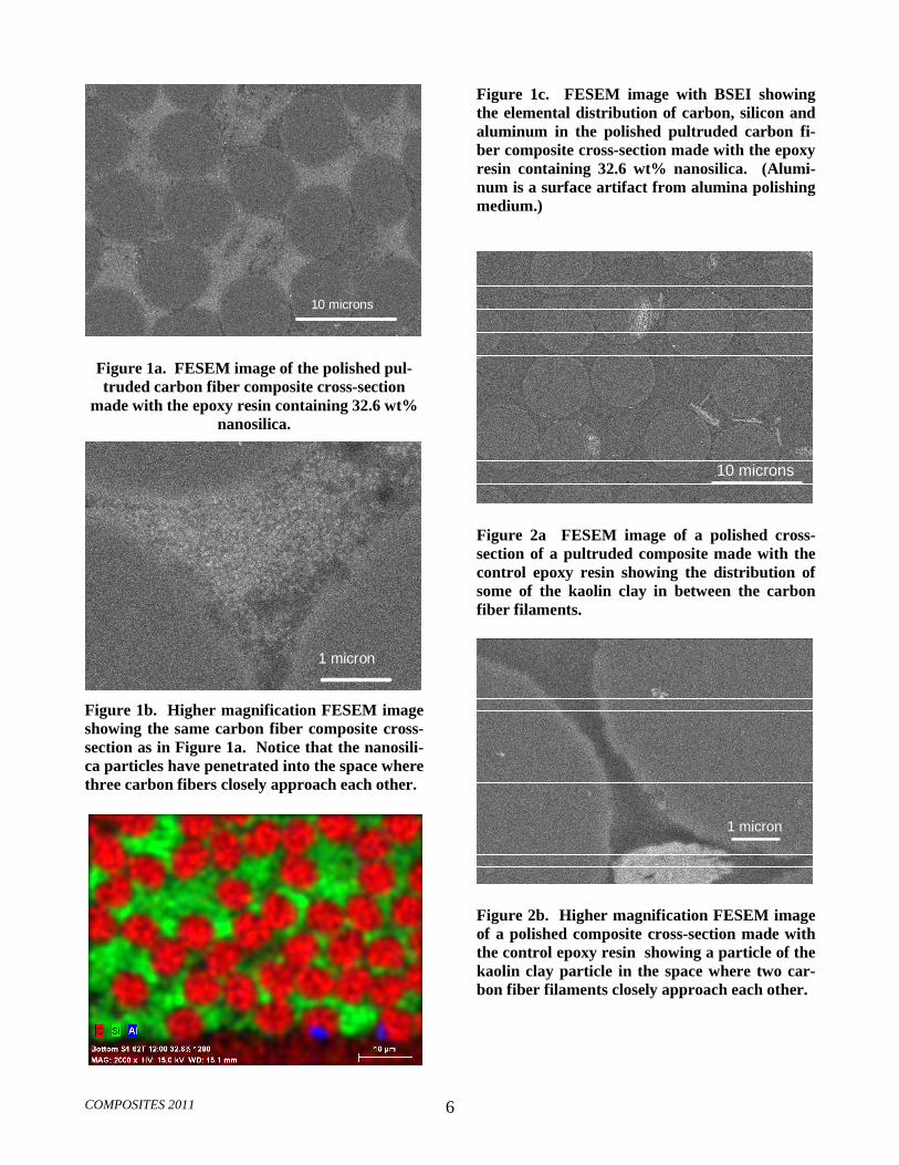
The final concentration of nanosilica in the cured resin system was 32.6% by weight of the resin. At such high particle content, the distribution of the particles is of particular interest. Figures 1a, 1b, and 1c contain the FESEM images of a cross-section of a pultruded epoxy carbon fiber composite containing the nanosilica-modified epoxy. The carbon fiber volume for the pul-truded sample in Figures 1a, b, and c is 64.3%. Figure 1a provides evidence that, due to the size of the nanosili-ca particles and their compatibility with the epoxy resin, the particles are distributed within the fiber tows of the composite. The nanosilica is visible as lighter gray spots between the carbon fibers. Figure 1b shows a higher magnification image of the nanoparticles in an interstitial space between three of the carbon fibers in the pultruded composite. From this view, the individual nanosilica particles are evident, as is their non-aggregated state. Figure 1c is a lower magnification elemental map show-ing carbon, silicon and aluminum distribution for a polished cross-section view of the pultruded carbon fiber composite part. The aluminum is not a part of the matrix resin or the fiber. It is surface contamination by colloidal alumina from the polishing process used to prepare the specimens for the FESEM analysis. The elemental map in Figure 1c provides additional evidence that the silica is distributed throughout the cross-section of the pul-truded part, even between the individual carbon fibers.
The FESEM images of the control epoxy pultruded sample are included here for comparison. Figures 2a and 2b show the FESEM images of a cross-section of a pul-truded epoxy carbon fiber composite containing the control epoxy resin with no nanosilica, but with 5 wt% clay filler. The carbon fiber volume for the pultruded sample in Figure 2a and 2b is 64.3%. In Figure 2a, some of the individual clay particles are visible in the lower right hand portion of the image. In Figure 2b, a higher magnification image of the cross-section shows a clay particle between two of the carbon fibers in the pultruded composite. A view of the elemental map of the control resin pultruded composite has not been included, but upon review, there was no silica present between the carbon fibers as was seen in Figure 1c.
3.2 Effect of Nanosilica-Containing Resin on the Pultrusion Process
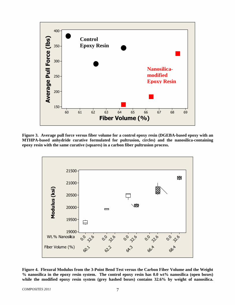
Figure 3 summarizes the effect of the inclusion of the nanosilica on the pull force measured in the pultru-sion process. In general, more viscous pultrusion resins tend to produce a higher level of pull force, relating to the viscous drag acting between the fibers and the die

COMPOSITES 2011 4
wall. Additionally, previous research has shown that the inclusion of nanosilica reduces the overall shrinkage in epoxy resins as they cure (5). Both the increase in epoxy resin system viscosity and the reduction in the resin shrinkage would cause one to expect that the inclusion of nanosilica in a pultrusion resin would cause pull force increases in the process. On the contrary, the results of this study show a definite decrease (54%) in pull force when the nanosilica-containing epoxy resin is run at equal fiber volume to the control resin.
Due to the significant reduction in pull force enabled by the inclusion of the nanosilica in the epoxy resin, greater carbon fiber volumes are enabled. In Fig-ure 3, it is evident that the pull force of the nanosilica-based epoxy resin becomes approximately equal to the pull force of the control resin when the carbon fiber vo-lume has been increased by at least 4.1 volume percent (from 64.3% to 68.4%). Stiffness is a critical design pa-rameter in pultrusion part design, and increasing the carbon fiber volume in a pultruded part will result in in-creased composite modulus, and thus, part flexural and axial stiffness. The use of the nanosilica-containing re-sins enables stiffer pultruded parts and, correspondingly, opens new design spaces to reach specific technical chal-lenges.
Another opportunity to exploit the pull force reduc-tion seen with the nanosilica-containing resins is to increase the line speed of the pultrusion process. Gener-ally in pultrusion manufacturing, line speed and curing conditions are manipulated to achieve a stable and sus-tainable process pull force. In the case of the nanosilica-containing resins, greater line speed can be accommo-dated due to the reduced pull force, leading to improvements in process efficiency, throughput, and cost savings in production.
Because of the process challenges experienced when pultruding epoxies, some manufacturers have di-rected product applications toward alternative chemistry resins such as vinyl esters to improve yields and produc-tion ease. With the introduction of nanosilica-containing epoxy resins, a new avenue has been opened which may enable the more widespread use of epoxies in pultrusion applications. For pultrusion applications in which epox-ies are already used, the reduced pull force enables the manufacturing of larger and more complex epoxy resin parts, and particularly carbon fiber reinforced products. The reduced exotherm during curing (seen in nanosilica-modified epoxy resins (5) and anticipated in these pultru-sion resins also) is also advantageous for pultruding thicker structures. The improved processing ease might be particularly important as building codes undergo fu-ture revisions and the use of epoxy-carbon fiber pultruded composites increasingly expands into the in-frastructure market which will demand large and complex structures for applications such as bridge sup-ports.
It is worth noting that in Figure 3 and subsequent figures, the maximum carbon fiber volume of the com-posites made with the control epoxy resin was 64.3% because that level represented the fiber volume at which a critical pull force was obtained. With the particular equipment and die geometry used in this evaluation, a steady pull force of no greater than about 350-400 pounds (160-180 kg force) was desired, as greater pull forces tended to result in erratic performance including sudden increases in pull force and product seizing in the die.
3.3 Effect of Nanosilica-Containing Resin on Mechanical Properties of Pultruded Com-posites
Figure 4 contains the flexural modulus as a function of the carbon fiber volume and the concentration of na-nosilica in the epoxy resin. As expected, the higher fiber volume fraction composite enabled by reduced pull force resulted in substantial increases in composite flexural modulus. Interestingly, the nanosilica-containing com-posite parts showed a slightly reduced flexural modulus (by 2%) in comparison to the pultruded samples of the control resin at an equal carbon fiber volume (64.3%). This modulus reduction effect was not an artifact and was repeated in the experimental evaluation. The au-thors hypothesize that the significantly lower pull force described in Figure 3 affected the fiber straightness and/or orientation in the die, and ultimately, the flexural modulus achieved at a certain carbon fiber volume. For-tunately, to address this concern in the future, it is a simple matter to increase pull force by increasing the line speed of the process. Line speed increases also help with process efficiency and throughput.
The boxplots in Figures 4, 5, and 8 represent data such that the top and bottom of the data boxes represent the first and third quartile of data, respectively, (the mid-dle 50% of data is contained within the box), and the horizontal line within the box signifies the data median.
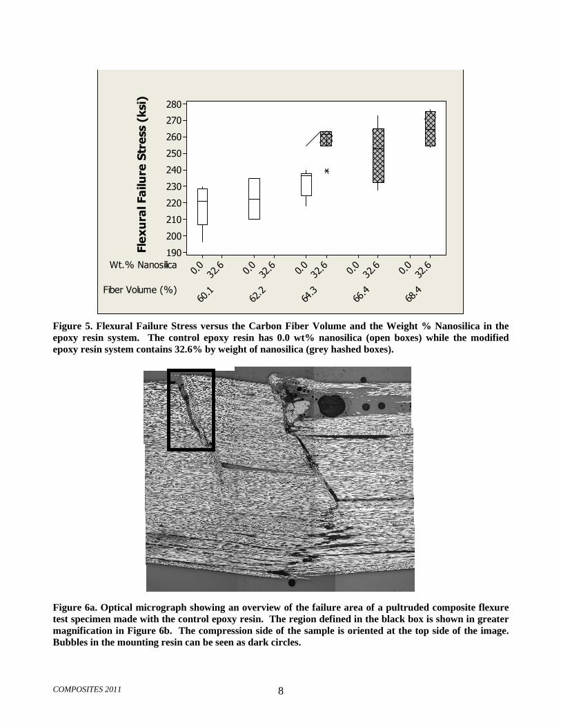
Other mechanical properties showed improvements with incorporation of nanosilica. Figure 5 shows the flexural failure stress as a function of carbon fiber vo-lume and the concentration of nanosilica in the epoxy resin. The failure stress is increased in comparison to the control samples for the samples made with the nanosili-ca-modified epoxy resin in which the cured system contains 32.6% by weight of nanosilica.
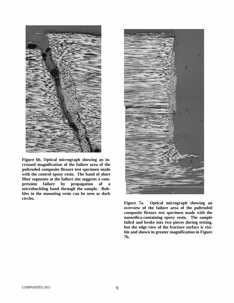
To investigate the failure mechanism in the flexure test, optical microscope images were obtained of the failure sites of control and the nanosilica-modified pul-truded composite flexural specimens. The compression sides of the specimens are oriented toward the top of the images in Figures 6 and 7. Figures 6a and 6b illustrate the failure zone of a control resin carbon fiber pultruded
COMPOSITES 2011 5
composite resulting from the 3-Point Bend Test, while Figures 7a and 7b illustrate a comparable region of sam-ples prepared using the nanosilica-modified epoxy resin.
The band of fiber segments at the failure site sug-gests that the flexure failure mechanism was compression failure by propagation of a fiber microbuck-ling band in both the control and the nanosilica-modified samples. The increase of flexural strength with the in-corporation of nanosilica is in accord with this failure mechanism (6). It is worth noting that the location of these images was close to the free edge of the sample, rather than the center of the sample failure region. In this situation, the fiber segments tended to buckle out toward the free surface of the specimen rather than re-maining in a vertical plane parallel to the specimen edge. (In the center of the specimen the constraint of adjacent material would force any fiber buckling to be in a vertic-al plane.) The resulting image shows fiber ends, rather than displaced fiber segments.
The mechanical property benefits to the composite parts of the inclusion of nanosilica are also evident when reviewing the results of the peak shear stress of the pul-truded control and nanosilica-modified epoxy samples. Figure 8 illustrates the peak shear stress (from the Short Beam Shear Test) as a function of carbon fiber volume and the concentration of nanosilica in the epoxy resin. The peak shear stress is significantly higher (approx-imately 16%) than the control samples in the samples made from the nanosilica-modified epoxy.
4. SUMMARY
In this study, the effect of a high level of nanosilica content in epoxy resins pultruded with carbon fiber was evaluated. Epoxy resins containing 32.6 wt.% nanosilica showed significant processing improvements in pultru-sion through reductions in the pull force, enabling increases in carbon fiber volume (product stiffness) and line speed. These improvements provide opportunities to address more demanding applications for pultruded products and/or to enjoy greater efficiencies and throughput in production. In addition to improved processing, mechanical property benefits were also ob-served with increases in the flexural failure stress and the peak shear stress of the pultruded parts.
5. FUTURE WORK
More research is warranted in the area of perfor-mance enhancement of nanosilica-containing resins in pultrusion processes to refine and expand on the con-cepts presented in this study. Further, the nanocomposite matrix resin technology described in this study is being leveraged into additional resin systems and adapted to other liquid composite processing techniques such as re-sin transfer molding and filament winding.
6. ACKNOWLEDGEMENTS
The authors would like to acknowledge Mike Hu-ehn of Pace Analytical Services for his assistance with resin preparation and Robert Shimanek of 3M Corporate Research Analytical Laboratory for his contributions of the FESEM images.
7. AUTHORS
Dr. Kristin Thunhorst, Senior Research Specialist, works in the area of Product Development for the nanosi-lica-modified epoxy resins. Dr. Douglas Goetz, Lead Research Specialist, is involved in understanding resin-composite property relationships for new composite ma-trix resin technologies. Andrew Hine, Advanced Product Development Engineer, and Paul Sedgwick, Master La-boratory Technician, both specialize in the mechanical testing of composites.
8. REFERENCES
1. Owens Corning, http://secure.owenscorning.net/Portal/uploads/document/20030717/58644_OC_Pultrusion.pdf , accessed Sep-tember 30, 2010.
2. P. Carlone and G.S. Palazzo, International Journal of Material Forming Proceedings of the 11th ESAFORM Conference on Material Forming, Springer / ESA-FORM, 2008, p. 833.
3. R. Boukhili, et.al, Polymer Composites, 27 (1) p. 71-81 (2006).
4. E. Lackey, et.al, Composite Institute’s International Conference Proceedings, CRC Press, 1999, p.21E 1-10.
5. S.C. Hackett, et.al, Proc. Fall SAMPE Technical Con-ference, SAMPE Publishing, 2010.
6. S.C. Hackett et.al., Proc. American Society for Com-posites 25th Annual Technical Conference, 2010.
COMPOSITES 2011 6
10 microns10 microns
Figure 1a. FESEM image of the polished pul-truded carbon fiber composite cross-section
made with the epoxy resin containing 32.6 wt% nanosilica.
1 micron1 micron
Figure 1b. Higher magnification FESEM image showing the same carbon fiber composite cross-section as in Figure 1a. Notice that the nanosili-ca particles have penetrated into the space where three carbon fibers closely approach each other.
Figure 1c. FESEM image with BSEI showing the elemental distribution of carbon, silicon and aluminum in the polished pultruded carbon fi-ber composite cross-section made with the epoxy resin containing 32.6 wt% nanosilica. (Alumi-num is a surface artifact from alumina polishing medium.)
10 microns10 microns
Figure 2a FESEM image of a polished cross-section of a pultruded composite made with the control epoxy resin showing the distribution of some of the kaolin clay in between the carbon fiber filaments.
1 micron1 micron
Figure 2b. Higher magnification FESEM image of a polished composite cross-section made with the control epoxy resin showing a particle of the kaolin clay particle in the space where two car-bon fiber filaments closely approach each other.
COMPOSITES 2011 7
69686766656463626160
400
350
300
250
200
150
Fiber Volume (%)
Average Pull Force (lbs)
Figure 3. Average pull force versus fiber volume for a control epoxy resin (DGEBA-based epoxy with an MTHPA-based anhydride curative formulated for pultrusion, circles) and the nanosilica-containing epoxy resin with the same curative (squares) in a carbon fiber pultrusion process.
Fiber Volume (%)
Wt.% Nanosilica
68.4
66.4
64.3
62.2
60.1
32.60.
032.60.
032.60.
032.60.
032.60.
0
21500
21000
20500
20000
19500
19000
Modulus (ksi)
Figure 4. Flexural Modulus from the 3-Point Bend Test versus the Carbon Fiber Volume and the Weight % nanosilica in the epoxy resin system. The control epoxy resin has 0.0 wt% nanosilica (open boxes) while the modified epoxy resin system (grey hashed boxes) contains 32.6% by weight of nanosilica.
Control Epoxy Resin
Nanosilica-modified Epoxy Resin
COMPOSITES 2011 8
Fiber Volume (%)
Wt.% Nanosilica
68.4
66.4
64.3
62.2
60.1
32.60.
032.60.
032.60.
032.60.
032.60.
0
280
270
260
250
240
230
220
210
200
190Flexural Failure Stress (ksi)
Figure 5. Flexural Failure Stress versus the Carbon Fiber Volume and the Weight % Nanosilica in the epoxy resin system. The control epoxy resin has 0.0 wt% nanosilica (open boxes) while the modified epoxy resin system contains 32.6% by weight of nanosilica (grey hashed boxes).
Figure 6a. Optical micrograph showing an overview of the failure area of a pultruded composite flexure test specimen made with the control epoxy resin. The region defined in the black box is shown in greater magnification in Figure 6b. The compression side of the sample is oriented at the top side of the image. Bubbles in the mounting resin can be seen as dark circles.
COMPOSITES 2011 9
Figure 6b. Optical micrograph showing an in-creased magnification of the failure area of the pultruded composite flexure test specimen made with the control epoxy resin. The band of short fiber segments at the failure site suggests a com-pression failure by propagation of a microbuckling band through the sample. Bub-bles in the mounting resin can be seen as dark circles.
Figure 7a. Optical micrograph showing an overview of the failure area of the pultruded composite flexure test specimen made with the nanosilica-containing epoxy resin. The sample failed and broke into two pieces during testing, but the edge view of the fracture surface is visi-ble and shown in greater magnification in Figure 7b.

COMPOSITES 2011 10
Figure 7b. Optical micrograph showing an in-creased magnification of the fracture edge of the pultruded composite flexure test specimen made with the nanosilica-containing epoxy resin. The band of short fiber segments at the failure site suggests a compression failure by propagation of a microbuckling band through the sample.
1

COMPOSITES 2011 11
Fiber Volume (%)
Wt.% Nanosilica
68.4
66.4
64.3
62.2
60.1
32.60.
032.60.
032.60.
032.60.
032.60.
0
14500
14000
13500
13000
12500
12000Peak Shear Stress (psi)
Figure 8. Peak Shear Stress from the Short Beam Shear Test versus the Carbon Fiber Volume % and the Weight % Nanosilica in the epoxy resin system. The control epoxy resin has 0.0 wt% nanosilica (open boxes) while the modified epoxy resin system contains 32.6% by weight of nanosilica (grey hashed boxes).


![EffectsofSizeofZincBorateontheFlameRetardantPropertiesof ...ammonium polyphosphate (APP) in TPU composites. Yan et al. [6] investigated the effects of nanosilica on the flame retardancy](https://static.fdocuments.net/doc/165x107/60b9bd3d55b3043ef571ef59/effectsofsizeofzincborateontheflameretardantpropertiesof-ammonium-polyphosphate.jpg)