COMPOSITE Testing of HVDC-connected offshore wind farms
44
© 2019 Electric Power Research Institute, Inc. All rights reserved. www.epri.com 1 COMPOSITE Testing of HVDC-connected offshore wind farms 11 th March 2021 | Webcast Oluwole Daniel Adeuyi & Benjamin Marshall, The National HVDC Centre. & Hani Saad & Markus Vor dem Berge, RTE International. www.slido.com Slido: #HVDC2021 We are expecting a large number of participants to join, so the session will start a couple of minutes late.
Transcript of COMPOSITE Testing of HVDC-connected offshore wind farms

© 2019 Electric Power Research Institute, Inc. All rights reserved.w w w . e p r i . c o m1
COMPOSITE Testing of HVDC-connected
offshore wind farms
11th March 2021 | Webcast
Oluwole Daniel Adeuyi & Benjamin Marshall, The National HVDC Centre.
&
Hani Saad & Markus Vor dem Berge, RTE International.
www.slido.com
Slido: #HVDC2021
We are expecting a large number of participants to join, so the session will start a couple of minutes late.

Page: 2
Welcome to our COMPOSITE Testing Webcast
Due to the large number
of participants, please
turn off video & put
microphone on mute
There will be Q&A at the end of the
session – please use Slido at any point to
ask your question. Feedbacks across the
presentation can be provided using MS
Teams chat.
Sections of the webinar will be
recorded. You will be informed on a
message via teams on which parts is
being recorded. Link to slides will be
shared after the webcast.
www.slido.com
Code: #HVDC2021
All questions or comments may not be addressed during the webcast. A briefing note with summary of
questions, answers and technical discussions will be published and circulated to all participants after the
webcast.
Expected
audience by
industry sector
Page: 3
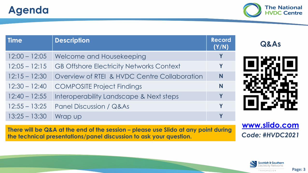
Agenda
www.slido.com
Code: #HVDC2021
Time Description Record
(Y/N)
12:00 – 12:05 Welcome and Housekeeping Y
12:05 – 12:15 GB Offshore Electricity Networks Context Y
12:15 – 12:30 Overview of RTEI & HVDC Centre Collaboration N
12:30 – 12:40 COMPOSITE Project Findings N
12:40 – 12:55 Interoperability Landscape & Next steps Y
12:55 – 13:25 Panel Discussion / Q&As Y
13:25 – 13:30 Wrap up Y
There will be Q&A at the end of the session – please use Slido at any point during the technical presentations/panel discussion to ask your question.
Q&As

Page: 4
Overview of Complex Electricity Connections
❑ Composite Testing required for coordinated control strategy
HVDC design – frequency response example HVAC design – Voltage dip example
❑ Coordinated Control Strategy needed – requires composite testing
Onshore AC Grid
Offshore AC SystemTest C
Offshore Wind TurbinesTest D
OffshoreOnshore
HVDC Cables
Offshore Converter Platform
Onshore Converter
StationHVDC Link
Test B
Grid IntegrationTest A
Onshore AC Grid
Offshore Network Test E
Wind Turbine Test F
OffshoreOnshore
STATCOM Test B
AC Network Filters Test C
Reactor Test D
Grid IntegrationTest A
❑ Complex electricity connections comprise multiple technologies provided by different manufacturers, with each
equipment control & protection tested in factory environment, but not across the composite system performance.
❑ HVDC centre with support of ESO compliance team commissioned COMPOSITE project
with RTEI to identify practical guidelines for composite testing of complex connections.
Page: 5
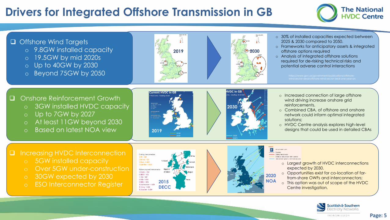
❑ Offshore Wind Targets
o 9.8GW installed capacity
o 19.5GW by mid 2020so Up to 40GW by 2030
o Beyond 75GW by 2050
❑ Onshore Reinforcement Growth
o 3GW installed HVDC capacity
o Up to 7GW by 2027
o At least 11GW beyond 2030
o Based on latest NOA view
❑ Increasing HVDC Interconnection
o 5GW installed capacity
o Over 5GW under-construction
o 30GW expected by 2030
o ESO Interconnector Register
https://www.gov.uk/government/publications/offshore-
wind-sector-deal/offshore-wind-sector-deal-one-year-on
o 30% of installed capacities expected between
2025 & 2030 compared to 2050.
o Frameworks for anticipatory assets & integrated
offshore options required
o Analysis of integrated offshore solutions
required for de-risking technical risks and
potential adverse control interactions
o Increased connection of large offshore
wind driving increase onshore grid
reinforcements.
o Combined CBA, of offshore and onshore
network could inform optimal integrated
solutions;
o HVDC Centre analysis explores high-level
designs that could be used in detailed CBAs
o Largest growth of HVDC interconnections
expected by 2030.
o Opportunities exist for co-location of far-
from-shore OWFs and interconnectors;
o This option was out of scope of the HVDC
Centre investigation.
20302019
2019
2030
2020 NOA2015
DECC
Drivers for Integrated Offshore Transmission in GB
Page: 6
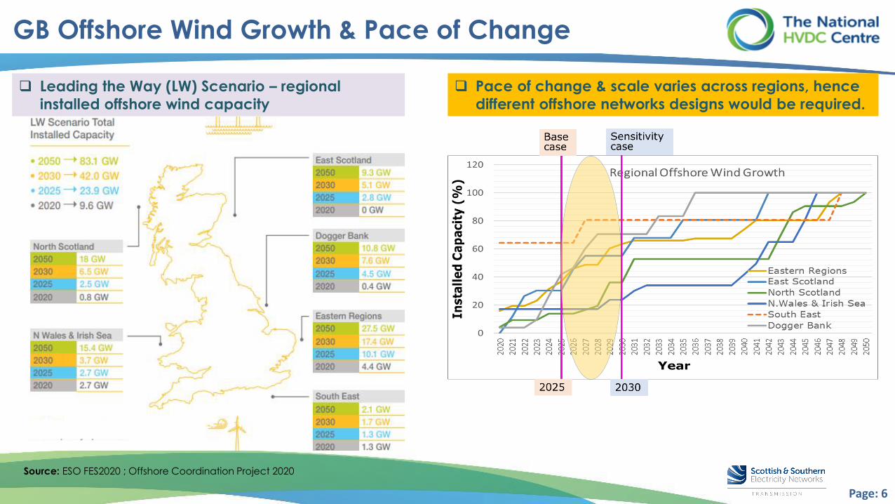
GB Offshore Wind Growth & Pace of Change
Source: ESO FES2020 ; Offshore Coordination Project 2020
❑ Leading the Way (LW) Scenario – regional
installed offshore wind capacity
❑ Pace of change & scale varies across regions, hence
different offshore networks designs would be required.

Page: 7
GB Implementation by 2050 – Key findings & policy impact
❑ Integrated offshore transmission approaches could offer up to 70% reduction in number of onshore landfall
locations with up to £6 billion consumer savings between 2025 & 2050, compared to current approach.
❑ Composite Testing is required: to ensure efficient, coordinated
& economic delivery of these
complex electricity
connections, comprising
multiple equipment.
❑ ESO OCP Phase 1 Final Report – published 16 Dec. 2020https://www.nationalgrideso.com/news/final-phase-1-report-our-offshore-coordination-project
Integration from 2025Integration from 2030Status Quo
How the offshore transmission network could look like by 2050…

Page: 8
HVDC EXPERTISEWebcast “Composite Testing of HVDC-connected Offshore Wind Farms”
11.03.2021, Markus Vor dem Berge, Director Power Electronics and Studies
HVDCExpertise-RTEi Page 8

Page: 9Page 9

Page: 10
WE PROMOTE THE FRENCH TSO’S EXPERTISE
Consultancy and studies
Technical assistance
Digital solutions
Maintenanceand procurement
Managed services
Engineering
Tel : +33 1 71 06 57 00 | Email [email protected] Page 10

Page: 11
OUR HVDC & FACTS SERVICES
Design Execution Operation
•
•
HVDC equipment technical
specification
•
•
Control and Protection
Factory test audit &
witnessing
•
•
•
System operation &
maintenance strategy
Improve specifications and
optimize system
performance
Control system change
managementPreparation of testing and
commissioning procedures
for HVDC/FACTS control and
protection systems• Tender Evaluation for HVDC
Applications - Negotiations
with EPC and OEM
Corrective patches testing
before deployment on site
by manufacturers•••
Site tests supervision
Change review••••
Cyber securityDesign review
and verificationIncident analysis
Incident management
Training
Real time digital simulator
testing of control and
protection systems
HVDCExpertise-RTEi
Engineering support
•
•Design and network studies
Integration studies
Interaction studies
•
Page 11

Composite Testing of HVDC-connected Offshore
Wind Farms
Dr. Hani SAAD 11/03/2021
Prepared by RTE internationalIn collaboration with HVDC CentrePage 12

CONTEXT➢ The work is intended to provide an overview on EMT modeling and studies for HVDC-OWF link projects
➢ The report is publicly available on HVDCCenter’swebsite
Report plan:Chapter 1: Overview on HVDC-OWF systemChapter 2: Type of tools for dynamic studiesChapter 3: EMT modeling of HVDC-OWF systemChapter 4: Dynamic studies during project phasesChapter 5: Generic case study - Parameter sensitivity on system performanceChapter 6: Case study over project lifecycle - Lessons learned based on RTE/RTE-I projectsChapter 7: Q&A
Page 13

System studies main challenges :1. Fast and complex behavior compared to the classical power system devices2. Complex control system designed by different manufacturers3. Several parties are involved
Converter transformer
BRK1
BRK2
Cable1
Cable2
OWFtransformer 1
WTG 1 WTG 2 WTG N
WTG 1 WTG 2 WTG N
OWFtransformer 2
WTG 1 WTG 2 WTG N
WTG 1 WTG 2 WTG N
AC switchyard
.. .
.. .
.. .
.. .
Feeder 1
Feeder 2
Feeder 3
Feeder 4
MMC station 2
MMC station 1
Converter
transformer DC cable
+-
1,000 MW 320kV
400kV AC network
CHAPTER 1: OVERVIEW ON HVDC-OWF SYSTEM
VSCstation
WTG 1 WTG 2 WTG N
Busbars
.. .
Feeder 11
Feeder 22
Feeder 21
Feeder 12
WTG 1 WTG 2 WTG N
.. .
... ... ... ...
...
...
... ... ......
.. .
... ... ... ...
...
... ... ......
WTG 1 WTG 2 WTG N
WTG 1 WTG 2 WTG N
...
Transformer 2
Transformer 1
.. .
DC cable
1,000 MW 320kV
Page 14

CHAPTER 2: TYPE OF TOOLS FOR DYNAMIC STUDIES
Load Flow
• Voltage Stability• Load flow studies• 50Hz models
RMS
• Transient stability • Electromechanical studies• 50 Hz models
EMT
• Electromagnetic behavior• Instantaneous voltages and currents• Dynamic studies• ~0 Hz to kHz models
Voltage
Voltage
5 s 10 s
Voltage
0.5 s 1 s~min Time Time Time
Page 15

CHAPTER 2: TYPE OF TOOLS FOR DYNAMIC STUDIES
Real-time EMT toolsUsing a hardware-in-the-loop (HIL) setup
Real time simulatorVoltage/current
measurements
CB status
Firing pulses
C&P systemPhysical equipment
ReplicasC&P system or Replicas
Page 16
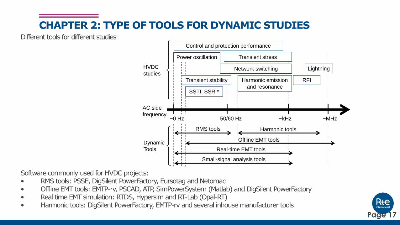
CHAPTER 2: TYPE OF TOOLS FOR DYNAMIC STUDIESDifferent tools for different studies
Software commonly used for HVDC projects:• RMS tools: PSSE, DigSilent PowerFactory, Eursotag and Netomac• Offline EMT tools: EMTP-rv, PSCAD, ATP, SimPowerSystem (Matlab) and DigSilent PowerFactory• Real time EMT simulation: RTDS, Hypersim and RT-Lab (Opal-RT)• Harmonic tools: DigSilent PowerFactory, EMTP-rv and several inhouse manufacturer tools
LightningNetwork switching
SSTI, SSR *
Transient stability Harmonic emission
and resonance
RMS tools
HVDC
studies
Dynamic
Tools
Control and protection performance
Harmonic tools
Transient stress
RFI
Offline EMT tools
Real-time EMT tools
AC side
frequency~0 Hz 50/60 Hz ~kHz ~MHz
Small-signal analysis tools
Power oscillation
Page 17
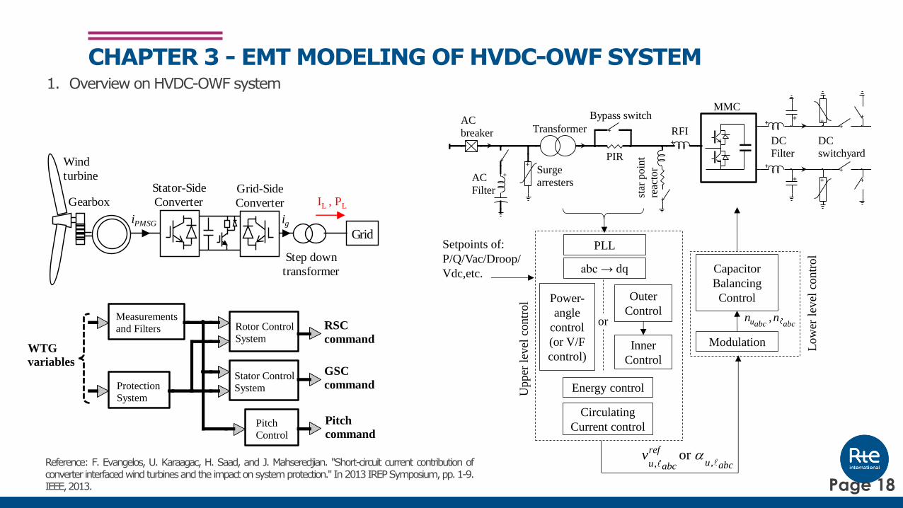
CHAPTER 3 - EMT MODELING OF HVDC-OWF SYSTEM1. Overview on HVDC-OWF system
Transformer
MMC
AC
breaker
Bypass switch
star
po
int
reac
tor
PIR
Surge
arresters
DC
switchyard
AC
Filter
DC
Filter
RFI+
+
+
+
++
+
++
++
+
+
+
++
Gearbox
Grid
Step down
transformer
Wind
turbine
iPMSG
Stator-Side
ConverterGrid-Side
Converter
ig
IL , PL
RSC
command
GSC
command
Pitch
command
WTG
variables
Measurements
and Filters
Protection
System
Pitch
Control
Stator Control
System
Rotor Control
System
or
gate signal
Capacitor
Balancing
Control
VSC-MMCmeasurements
Modulation Low
erle
vel
contr
ol
,,or ref
uu abcabcv
,uabc abcn n
Outer
Control
Inner
Control
Upper
level
contr
ol Power-
angle
control
(or V/F
control)
abc → dq
PLL
Energy control
Circulating
Current control
Setpoints of:
P/Q/Vac/Droop/
Vdc,etc.
Reference: F. Evangelos, U. Karaagac, H. Saad, and J. Mahseredjian. "Short-circuit current contribution ofconverter interfacedwindturbinesand the impactonsystemprotection." In2013IREPSymposium,pp.1-9.IEEE,2013. Page 18

CHAPTER 4 - DYNAMIC STUDIES DURING PROJECT PHASES
EMT studies should be performed at eachphase to de-risk the project
-> This chapter is based on Cigré WG B4-70
Identifying the needs and alternative solutions
Economical and environmental
impact comparison of the
alternatives
Preliminary specification of
the selected scheme
Specification of the existing
system properties
Performance requirements for
the scheme
Detailed equipment
requirements
Protection and control system
settings
Simulation of critical system
tests
Investmentdecision
Awarding of the contract
Commissioning
Operation and maintenance
Feasibility studies
Specification studies
Implementation studies
Studies during operation
Installation of control system on site
Preliminary design studies
Planning
Bid/ Tender
Implementation
Operation
Reference: Cigré WG B4-70, “Guide for Electromagnetic Transient Studies Involving VSC converters”
Page 19

To provides illustrative example of HVDC-OWF system dynamic operation using generic model in EMT softwareTo illustrate the impact of OWF on HVDC performance, different WTG model are used (1 generic and 3 vendor’smodel that are all compliant with onshore gride code)
Dynamic studies performed are:- Offshore Step change on Vac and Frequency reference- AC fault onshore and offshore- DC pole-to-ground fault- Onshore load rejection and frequency control response
CHAPTER 5 - GENERIC CASE STUDY
Aggregated Cable
OWF transformer
WTGType 4
AC switchyard
MMC1 MMC2
DC cable
+-
1,000 MW
320kV
2.7 GW
0.5 GW
200 km
PQMMC1 PQOWFPQ MMC2
BRK12.3 GW
H = 6.1 s
PQSM
Generi or
Vendor A or
Vendor B1 or
Vendor B2
Fault 2 Fault 1
1 2SM
Page 20
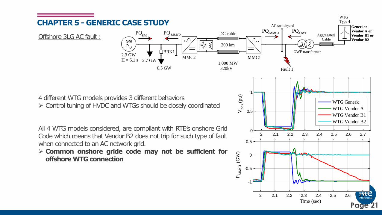
Offshore 3LG AC fault :
4 different WTG models provides 3 different behaviors➢ Control tuning of HVDC and WTGs should be closely coordinated
All 4 WTG models considered, are compliant with RTE’s onshore GridCode which means that Vendor B2 does not trip for such type of faultwhen connected to an AC network grid.➢ Common onshore gride code may not be sufficient for
offshore WTG connection
CHAPTER 5 - GENERIC CASE STUDY
2 2.1 2.2 2.3 2.4 2.5 2.6 2.70
0.5
1
Vp
os
(pu
)
Time (sec)
WTG Generic
WTG Vendor A
WTG Vendor B1
WTG Vendor B2
2 2.1 2.2 2.3 2.4 2.5 2.6 2.7
-1
-0.5
0
0.5
PM
MC
1 (
GW
)
Time (sec)
Aggregated Cable
OWF transformer
WTGType 4
AC switchyard
MMC1 MMC2
DC cable
1,000 MW 320kV
2.7 GW
0.5 GW
200 km
PQMMC1 PQOWFPQ MMC2
BRK12.3 GWH = 6.1 s
PQSM
Generi or Vendor A or Vendor B1 or Vendor B2
Fault 1
1 2SM
Page 21

500MW onshore load rejection :
➢ Both frequency control approaches work properly when it is well coordinated.➢ When coordination is not properly done, in this test case, a 3.4 Hz oscillation
appears : this frequency range oscillation is a systemic issue that is within thebandwidth of several C&P systems in HVDC as well as in WTGs and can propagatein the onshore grid
CHAPTER 5 - GENERIC CASE STUDY
WTGType 4
AC switchyard
MMC1 MMC2
DC cable
+-
1,000 MW
320kV
2.3 GW
H = 6.1 s 2.7 GW
0.5 GW
PQSM
PQMMC1 PQOWFPQ MMC2
Pref
OWF Frequency contol
BRK1
onshoreFreq
System
operator
SM 1 2
LP filterDeadband
WTGType 4
AC switchyard
MMC1 MMC2
DC cable
+-
1,000 MW
320kV
2.3 GW
H = 6.1 s 2.7 GWLoad 1
0.5 GW
PQSM
PQMMC1 PQOWFPQ MMC2
Pref
OWF Frequency contolMMC1 Frequency contol
BRK1
refFreqonshoreFreq
offshoreFreq
SM 1 2
LP filterDeadband
LP filterDeadband
Frequency control #1 Frequency control #2
8 10 12 14 16 18 20 22 24 26 28
50
50.5
51
51.5
52
52.5
Fre
qO
nsh
ore
(p
u)
Time (sec)
FreqCtrl#2
FreqCtrl #1
without FreqCtrl
8 10 12 14 16 18 20 22 24 26 280.2
0.4
0.6
0.8
1
PM
MC
2 (
GW
)
Time (sec)
FreqCtrl#2
FreqCtrl #1
without FreqCtrl
10 12 14
0
0.2
0.4
0.6
0.8
1
PM
MC
2 (
GW
)
Time (sec)
10 12 14
50
50.5
51
Fre
q Off
sho
re
(Hz)
Time (sec)
Tuning #3
Tuning #2
Tuning #1
Control tuning impact:
Page 22

5.1. AC Temporary Overvoltage after voltage recovery –planning stage studyTo improve specification
CHAPTER 6 - CASE STUDIES OVER PROJECT LIFECYCLE - LESSON LEARNED BASED ON REAL PROJECTS
2.9 3 3.1 3.2 3.3 3.4 3.5 3.60
0.2
0.4
0.6
0.8
1
1.2
1.4
1.6
VR
MSL
L (
pu
)
times (s)
0 20 40 60 80 100 1201.1
1.2
1.3
1.4
1.5
1.6
max
peak
VR
MSL
L (
pu
)Simulations
with HVDC-LCC linkwithout HVDC-
LCC link
Parameters Number of configurations
Impact of HVDC-LCC
link
• HVDC-LCC link included with active
power transits of ± 1000 MW
• HVDC-LCC link excluded
P/Q setpoints of the
HVDC-VSC link
± 1000 MW, ± 800 MW, 0 MW
-300 MVar
Fault resistance 0, 10, 30 and 50
Settling time of the
VSC Inner control7 and 10 ms
IFA2000 Link
HVDC-LCC 1GW
HVDC-MMC link 1GW
Fault1
ACgrid1
ACgrid
ACgrid2
Mandarins
Page 23

5.3. Pole-to-ground fault event– study during operationIFA2000 link incident November 2016)
➢ Incident reproduction using Replicas➢ Importance of accurate modeling
CHAPTER 6 - CASE STUDIES OVER PROJECT LIFECYCLE
Pole-to-ground voltage
Alpha angle DC current
When inaccurate
cable model is used
Page 24
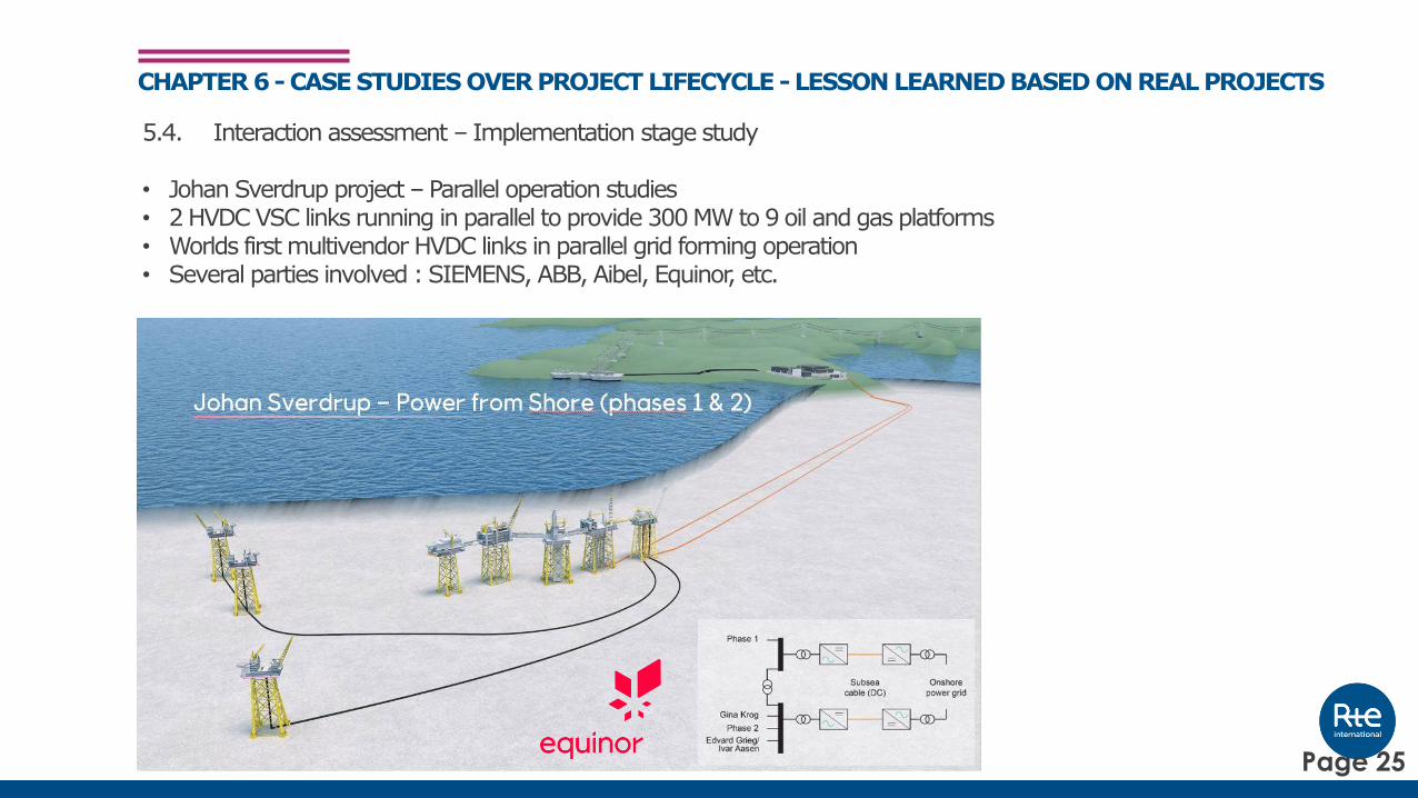
5.4. Interaction assessment – Implementation stage study
• Johan Sverdrup project – Parallel operation studies• 2 HVDC VSC links running in parallel to provide 300MW to 9 oil and gas platforms• Worlds first multivendor HVDC links in parallel grid forming operation• Several parties involved : SIEMENS, ABB, Aibel, Equinor, etc.
CHAPTER 6 - CASE STUDIES OVER PROJECT LIFECYCLE - LESSON LEARNED BASED ON REAL PROJECTS
PMS
Simulator/ model from HVDC 1
Interaction testing (PSCAD and RTS)
Dynamic FAT HVDC 2
Commissioning HVDC 2
Pretested simulator/ model
from HVDC 2
Detailed offshore network models
Retesting interaction in case of substantial changes
Testing of overlaid platform controls
Coordinator :
Page 25

5.4. Interaction assessment – Implementation stage study
CHAPTER 6 - CASE STUDIES OVER PROJECT LIFECYCLE - LESSON LEARNED BASED ON REAL PROJECTS
Offline EMT studies:
Real-time EMT studies:
Page 26

5.4. Interaction assessment – Implementation stage study• Coordination between mutli-vendors
CHAPTER 6 - CASE STUDIES OVER PROJECT LIFECYCLE - LESSON LEARNED BASED ON REAL PROJECTS
PMS
Simulator/ model from HVDC 1
Interaction testing (PSCAD and RTS)
Dynamic FAT HVDC 2
Commissioning HVDC 2
Pretested simulator/ model
from HVDC 2
Detailed offshore network models
Retesting interaction in case of substantial changes
Testing of overlaid platform controls
Coordinator :
Reference : S. Dennetière, P. Rault, K. Sharifabadi, H. Saad, J.H. Johansson, N. Krajisnik “Technical
solutions to predict and mitigate inadvertent interaction of two parallel connected VSC-HVDC schemes
feeding an islanded offshore Oil and Gas grid” CIGRE Conference, Paris, France, Aug. 2020
Page 27

5.4. Interaction assessment – Implementation stage study
CHAPTER 6 - CASE STUDIES OVER PROJECT LIFECYCLE - LESSON LEARNED BASED ON REAL PROJECTS
Norway
North Sea DC ±80 kV
AC 300 kV
AC 110 kV
PHASE 1 HVDC
AC 33 kV
Harmonic Filter
Kårstø
DC ±80 kV
AC 300 kV
PHASE 2 HVDC
Haugsneset
Harmonic Filter
PHASE 1 HVDCPHASE 2 HVDC
AC 11 kV
Johan Sverdrup PH1Johan Sverdrup PH2
AC 11 kV
Gina Krog
Edvard Grieg
AC 11 kV
Ivar Aasen
AC 110 kV
AC 110 kV
AC 33 kV
AC 11 kV
AC 11 kV
Essential generator
Impact of offshore
generation (voltage
and frequency control)
Impact of:
▪ Converter controls
▪ Harmonic interactions
▪ Converter protections
Impact of:
▪ Load characteristics to
voltage stability
▪ Transformers and
cables energizations
▪ Load rejection
Impact of:
▪ Load sharing
▪ Synchronisation
▪ Decoupling
Impact of:
▪ Offshore fault
▪ Onshore fault
Page 28

5.6. Inter-area oscillation – study during operation
East-Centre-West inter-area oscillation event occurred on 1st December 2016
CHAPTER 6 - CASE STUDIES OVER PROJECT LIFECYCLE - LESSON LEARNED BASED ON REAL PROJECTS
Reference: “Analysis of CE Inter-Area Oscillations of 1st
December 2016”, ENTSO-E SG SPD Report, 13.07.2017
Page 29

5.6. Inter-area oscillation – study during operationEast-Centre-West inter-area oscillation event occurred on 1st December 2016Scopes of study for the Real-time simulation with replicas:• to validate and improve the RMS INELFE model• to test mitigation solution that has been proposed• to identify the exact C&P parameters that should be modified onsite• to write the procedure that should be used by the operator for onsite modification• to develop a benchmark test for future project and future software updates during lifecycle operation
CHAPTER 6 - CASE STUDIES OVER PROJECT LIFECYCLE - LESSON LEARNED BASED ON REAL PROJECTS
0 20 40 60 80 1000
200
400
600
800
1000
PH
VD
C(M
W)
time (s)
Tuning #2
Tuning #1
0 20 40 60 80 1000.5
1
1.5
2
a
ng
le (
deg
ree)
time (s)
INELFE link
Station 1 Station 2
H1
10 GW
H2
10 GW
L1
8 GWL3
1 GW
L2
11 GW
Zline1
Zline2
BRK1
BRK2BRK3Zline3
PCC1 PCC2
P PHVDCTotal
SM SM
Page 30

• HVDC systems are becoming more complex, with more variation in controls, and co-ordination performance across more devices.
• Simulation and Tests of this nature are becoming increasingly important, using a range of offline, real-time and HIL approaches.
• These activities should be done across a range of potential operating points, and at key points in the design and commissioning of projects.
• The report provides a guideline for HVDC-OWF EMT modeling, studies to be performed during project phases, general dynamic behavior of HVDC-OWF system and, as well as real case studies based on RTE/RTE-I experiences.
SUMMARY
Page 31
www.slido.com
Code: #HVDC2021
Q&As

Page: 32
Evolution of Converter technology in GB…
To early 2000s c. 2005 onwards c. 2013 onwards today
LCC & other
Thyristor based
technologies
VSC & other IGBT based
technologies
VSC & other IGBT
based technologies,
Storage devices
1st Gen Control &
Protection (C&P)2nd Gen C&P 3rd Gen C&P 4th Gen C&P
Type 1-4 WTG
transition

Page: 33
Some key facets of Converter technology around today
Power System performance area Legacy (early/ small scale)
2nd Generation Grid follow & withstand
3rd Generation Grid follow & support
4th Generation; Grid forming, stabilising
1. Fault ride through and recovery None/ limited Yes Yes Yes
2. RoCoF & Vector Shift sensitivity LoM and control-based sensitivities
Different LoM considerations, control based sensitivity remain
Lesser control based sensitivities, potentially still LoM
No
3. Steady state and dynamic voltage support
None/ limited Yes Yes Yes
4. Fast fault current & transient voltage support
no no Yes, but may not be aligned with protection need
Yes- aligned with protection need
5. Low SCL resilience no no Yes but may require careful tuning
Yes
6. Inertial voltage & frequency support
no no No Yes –inherent to control concept
7. Black start capable no no Potential options
8. Proportions connecting on GB system today
c.20% c.30% c. 50% >1%, more to come?
These are facets of control and protection capabilities and priorities….

Page: 34
Differences within Converter technology
COMPOSITE project illustrates:-
• Perfectly compliant convertor solutions for wind turbines, but-can have very different behaviours within an offshore HVDC
connected environment!• Different responses to:
• Offshore faults;
• During onshore disturbances;• For small signal disturbances offshore.
• These inform:• Damping controls on offshore HVDC converters and;
• Over-arching supervisory controls across HVDC
converters.As projects share more infrastructure, these findings, and the
associated solutions for them become more relevant…

Page: 35
Convertor performance can be part of the problem…. or part of the solution= COMPOSITE findings direct how to solve.
o Single point failure risks, as network conditions change-and more complex designs emerge.
o Tracking and managing changes occurring over lifetime.
o Completeness of information and analysis possible ahead of connection.
o Hidden project interactions.
o New vulnerabilities…
o Hidden project behaviours.
o Completeness of codes & standards & Data Exchange.
https://www.smarternetworks.org/project/nia_nget0187/documents
https://www.nationalgrideso.com/publications/system-operability-framework-sof
https://www.nationalgrideso.com/publications/system-operability-framework-sof
https://www.nerc.com/pa/rrm/ea/1200_MW_Fault_Induced_Sol
ar_Photovoltaic_Resource_/1200_MW_Fault_Induced_Solar_Pho
tovoltaic_Resource_Interruption_Final.pdf
https://www.wecc.org/Administrative/14_RTE-Interarea%20oscillations.pdf
https://www.aemo.com.au/-/media/Files/Electricity/NEM/Market_Notices_and_Events/Power_System_Incident_Reports/2017/Integrated-Final-Report-SA-Black-System-28-September-2016.pdf
https://www.ofgem.gov.uk/publications-and-updates/investigation-9-august-2019-power-outage
High convertor concentration: Technical Risks
https://www.aanmelder.nl/ac-dc/wiki/470968/presentations
o New
simulation
environments
o IP &
confidentiality
management
o Operational
simulation
o Wide range of
conditions
o Hosted Project
testing
o New data
exchanges
COMPOSITE
Page: 36
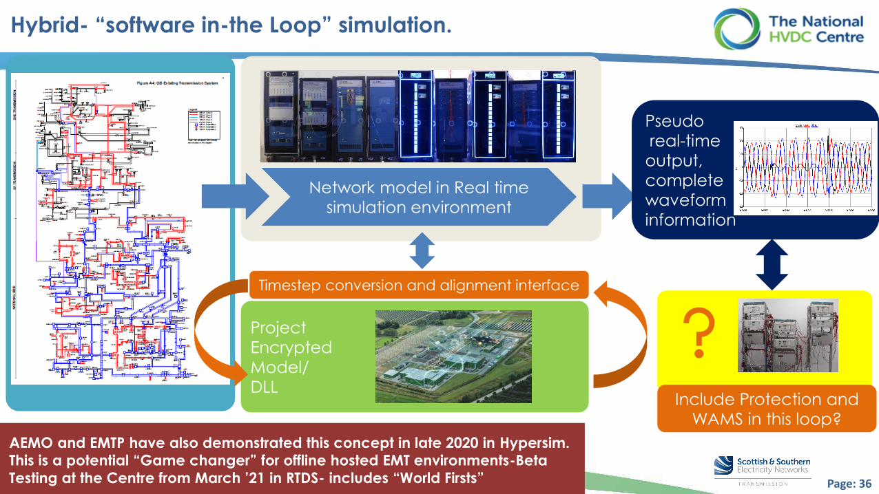
Project
Encrypted
Model/
DLL
Hybrid- “software in-the Loop” simulation.
Network model in Real time
simulation environment
Timestep conversion and alignment interface
Pseudo
real-time
output,
complete
waveform
information
Include Protection and
WAMS in this loop?
AEMO and EMTP have also demonstrated this concept in late 2020 in Hypersim.
This is a potential “Game changer” for offline hosted EMT environments-Beta
Testing at the Centre from March ’21 in RTDS- includes “World Firsts”
Page: 37
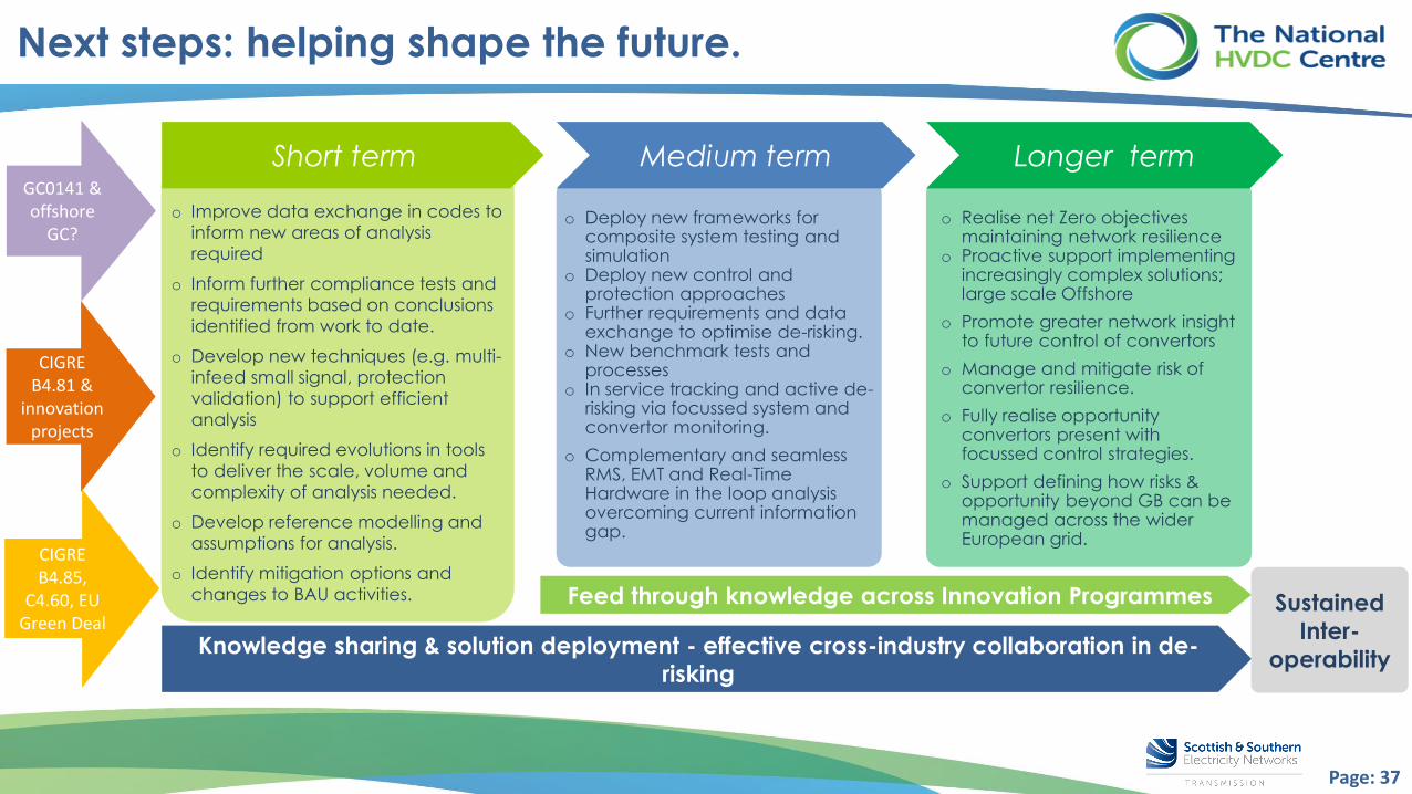
Next steps: helping shape the future.
o Improve data exchange in codes to
inform new areas of analysis
required
o Inform further compliance tests and
requirements based on conclusions
identified from work to date.
o Develop new techniques (e.g. multi-
infeed small signal, protection
validation) to support efficient
analysis
o Identify required evolutions in tools
to deliver the scale, volume and
complexity of analysis needed.
o Develop reference modelling and
assumptions for analysis.
o Identify mitigation options and
changes to BAU activities.
Short term
o Deploy new frameworks for composite system testing and simulation
o Deploy new control and protection approaches
o Further requirements and data exchange to optimise de-risking.
o New benchmark tests and processes
o In service tracking and active de-risking via focussed system and convertor monitoring.
o Complementary and seamless RMS, EMT and Real-Time Hardware in the loop analysis overcoming current information gap.
Medium term
o Realise net Zero objectives maintaining network resilience
o Proactive support implementing increasingly complex solutions; large scale Offshore
o Promote greater network insight to future control of convertors
o Manage and mitigate risk of convertor resilience.
o Fully realise opportunity convertors present with focussed control strategies.
o Support defining how risks & opportunity beyond GB can be managed across the wider European grid.
Longer term
Feed through knowledge across Innovation Programmes
Knowledge sharing & solution deployment - effective cross-industry collaboration in de-
risking
GC0141 & offshore
GC?
CIGRE B4.81 &
innovation projects
CIGRE B4.85,
C4.60, EU Green Deal
Sustained
Inter-
operability
Page: 38
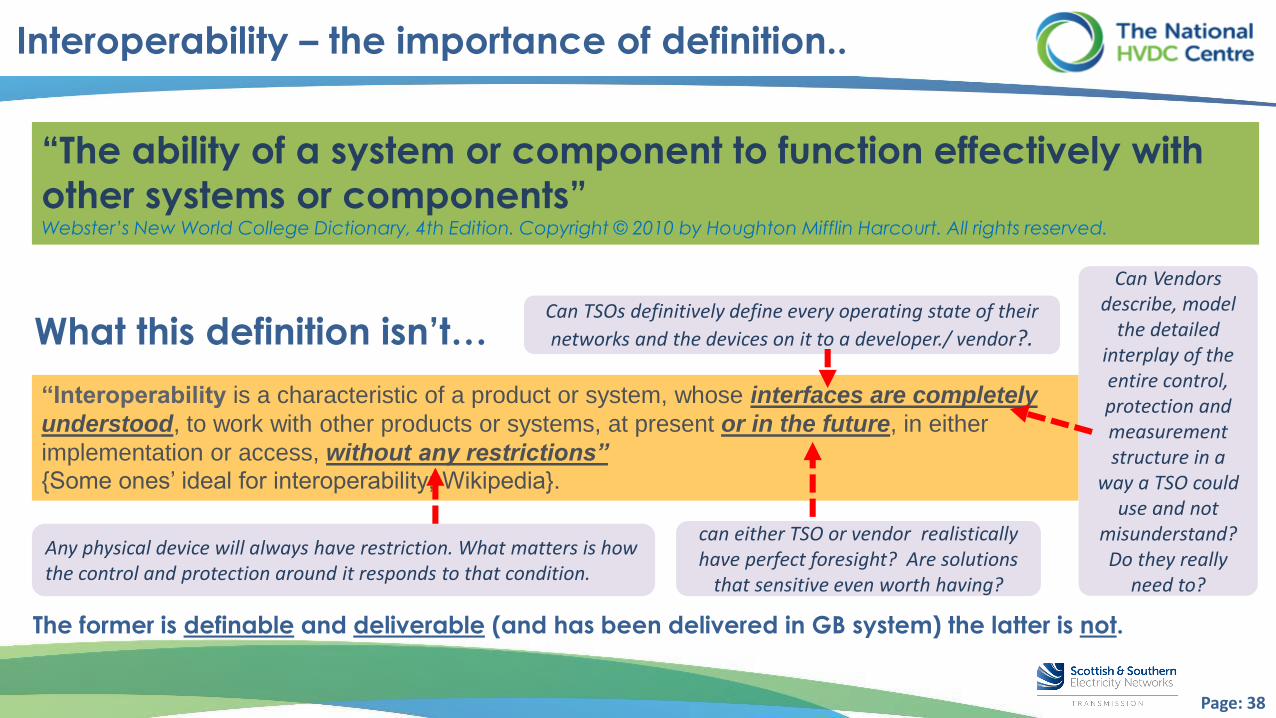
Interoperability – the importance of definition..
What this definition isn’t…
“The ability of a system or component to function effectively with
other systems or components”Webster’s New World College Dictionary, 4th Edition. Copyright © 2010 by Houghton Mifflin Harcourt. All rights reserved.
“Interoperability is a characteristic of a product or system, whose interfaces are completely
understood, to work with other products or systems, at present or in the future, in either
implementation or access, without any restrictions”
{Some ones’ ideal for interoperability; Wikipedia}.
The former is definable and deliverable (and has been delivered in GB system) the latter is not.
Can TSOs definitively define every operating state of their
networks and the devices on it to a developer./ vendor?.
Can Vendors describe, model
the detailed interplay of the entire control, protection and measurement structure in a
way a TSO could use and not
misunderstand? Do they really
need to?
can either TSO or vendor realistically have perfect foresight? Are solutions
that sensitive even worth having?
Any physical device will always have restriction. What matters is how the control and protection around it responds to that condition.

Page: 39
Interoperability challenges- focussing on the right ones!
Managing technological interoperability… Managing scale & range of interaction risk
o These are challenges of the past
now its not about how to manage, but more to continue
to refine and improve efficiencies of approach..
Managing manufacturer interoperability… Managing complex topology/requirements
o These are challenges of the future; relate to
control and protection clarity; overcoming the
“Information gap”
…
Islanded
network
110 and
33 kV
……
…
HVDC Phase-1
HVDC Phase-2
Cable 200 km
80 kV
Cable 200 km
80 kV +Onshore
AC network
300 kV
Page: 40
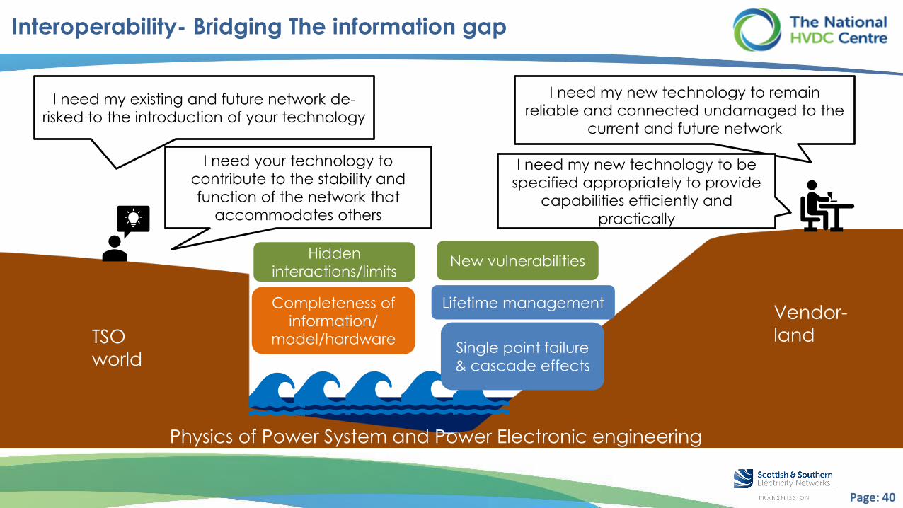
Interoperability- Bridging The information gap
Vendor-
landTSO
world
I need my existing and future network de-
risked to the introduction of your technology
Physics of Power System and Power Electronic engineering
Single point failure
& cascade effects
Lifetime managementCompleteness of
information/
model/hardware
Hidden
interactions/limitsNew vulnerabilities
I need your technology to
contribute to the stability and
function of the network that
accommodates others
I need my new technology to remain
reliable and connected undamaged to the
current and future network
I need my new technology to be
specified appropriately to provide
capabilities efficiently and
practically

Page: 41
Vendor-
landTSO
world
I will tell you how to meet my
requirement, not why
Physics of Power System and Power Electronic engineering
I will tell you what I think achieves
that, and solve the rest
Bridging the Information gap…the wrong way
Interoperability risks
exist
Oh dear
Oh dear

Page: 42
Vendor-
landTSO
world
I will explain what I am trying to
achieve, and why
Physics of Power System and Power Electronic engineering
I will tell you what information I need from
you to achieve that, and why I need it
Interoperability risks
managed
Ok, that should work- but we both need to have a way of simulating the whole solution,
to de-risk its implementation, and handle issues of IP and confidentiality within this exchange.
Bridging the Information gap… the right way

Page: 43
Panel Discussion / Q&A’s
❑ Panellists:
o Cornel Brozio - Network Planning & Regulation, SP Energy Networks;
o Markus Vor dem Berge – Director Power Electronics & Studies, RTEI
o Razvan Pabat-Stroe – Offshore Project Services, ScottishPower Renewables.
www.slido.com
Code: #HVDC2021
❑ Speakers:
o Hani Saad – HVDC Expert, RTE International
o Benjamin Marshall – HVDC Technology Manager, The National HVDC Centre
❑ Session Chair:
o Oluwole Daniel Adeuyi – Offshore Networks Lead, The National HVDC Centre
Q&As

© 2020 Electric Power Research Institute, Inc. All rights reserved.w w w . e p r i . c o m44
Thanks for listening.
Any questions, please?
❑ For further information, please visit www.hvdccentre.com ; OR email: [email protected]
❑ Register for upcoming Webcast on: 22 March at 2pm – 4.30pm GMT: Introduction to HVDC Technology and Grid Integration Challenges for Beginners. Click here OR use link: https://bit.ly/3v71Tyy
❑ 29 April : COMPOSITE project additional webinar co-hosted with EMTP, RTEI & the HVDC Centre.
Follow us on Twitter @HVDC_Centre_GB
Follow our Linkedin page The National HVDC Centre for regular updates.
We are recruiting NOW for a Simulation Engineer.