Composite Car Rear Spoiler - Ammattikorkeakoulut
82
Composite Car Rear Spoiler Sandy Minkah Kyei Degree Thesis Plastics Technology 2014
Transcript of Composite Car Rear Spoiler - Ammattikorkeakoulut
Composite Car Rear Spoiler
Sandy Minkah Kyei
Degree Thesis
Plastics Technology
2014
DEGREE THESIS
Arcada
Degree
Programme:
Plastics Technology
Identification
number:
Author: Sandy Minkah Kyei
Title: Composite Car Rear Spoiler
Supervisor
(Arcada):
Rene Hermann
Commissioned
by:
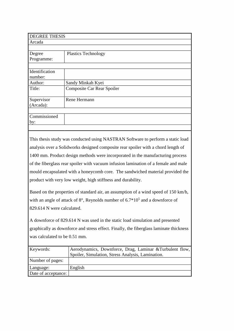
This thesis study was conducted using NASTRAN Software to perform a static load
analysis over a Solidworks designed composite rear spoiler with a chord length of
1400 mm. Product design methods were incorporated in the manufacturing process
of the fiberglass rear spoiler with vacuum infusion lamination of a female and male
mould encapsulated with a honeycomb core. The sandwiched material provided the
product with very low weight, high stiffness and durability.
Based on the properties of standard air, an assumption of a wind speed of 150 km/h,
with an angle of attack of 8°, Reynolds number of 6.7*105 and a downforce of
829.614 N were calculated.
A downforce of 829.614 N was used in the static load simulation and presented
graphically as downforce and stress effect. Finally, the fiberglass laminate thickness
was calculated to be 0.51 mm.
Keywords: Aerodynamics, Downforce, Drag, Laminar &Turbulent flow,
Spoiler, Simulation, Stress Analysis, Lamination.
Number of pages:
Language: English
Date of acceptance:

ACKNOWLEDGEMENT
I would like to thank Almighty God for His Grace for steadfastly guiding me to achieve my
academic goal. I would also like to thank Mr. Rene Hermann my supervisor for his direction
and insight. A heart of gratitude goes to the staff and lecturers of Arcada UAS especially to
the Energy and Material Technology department for their readiness to impact knowledge to
the students.
Finally, a warmth salutation goes to my family for their endless love and support, I gladly say
in my heart, is where I will keep all of you as a secret.
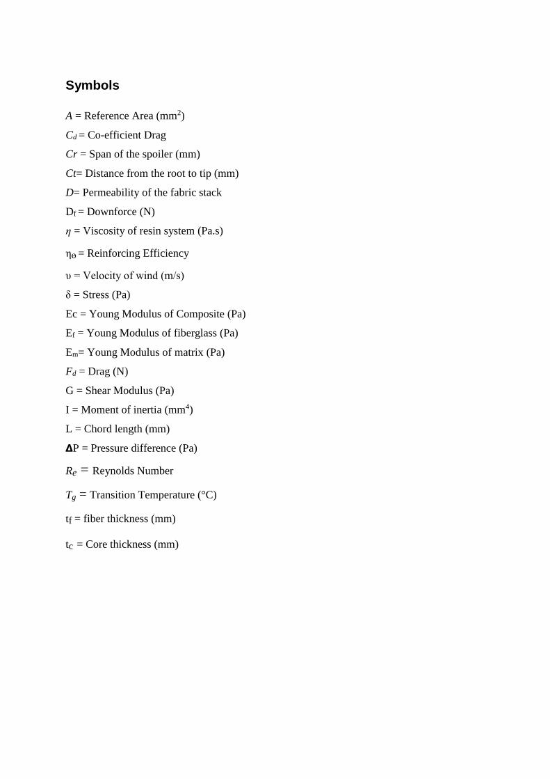
Symbols
A = Reference Area (mm2)
Cd = Co-efficient Drag
Cr = Span of the spoiler (mm)
Ct= Distance from the root to tip (mm)
D= Permeability of the fabric stack
Df = Downforce (N)
η = Viscosity of resin system (Pa.s)
ηɵ = Reinforcing Efficiency
υ = Velocity of wind (m/s)
δ = Stress (Pa)
Ec = Young Modulus of Composite (Pa)
Ef = Young Modulus of fiberglass (Pa)
Em= Young Modulus of matrix (Pa)
Fd = Drag (N)
G = Shear Modulus (Pa)
I = Moment of inertia (mm4)
L = Chord length (mm)
𝝙P = Pressure difference (Pa)
Re = Reynolds Number
Tg = Transition Temperature (°C)
tf = fiber thickness (mm)
tc = Core thickness (mm)
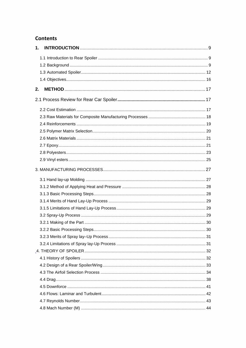
Contents
1. INTRODUCTION ................................................................................................... 9
1.1 Introduction to Rear Spoiler ................................................................................................ 9
1.2 Background ......................................................................................................................... 9
1.3 Automated Spoiler ............................................................................................................. 12
1.4 Objectives.......................................................................................................................... 16
2. METHOD ............................................................................................................. 17
2.1 Process Review for Rear Car Spoiler .................................................................... 17
2.2 Cost Estimation ................................................................................................................. 17
2.3 Raw Materials for Composite Manufacturing Processes .................................................. 18
2.4 Reinforcements ................................................................................................................. 19
2.5 Polymer Matrix Selection ................................................................................................... 20
2.6 Matrix Materials ................................................................................................................. 21
2.7 Epoxy ................................................................................................................................. 21
2.8 Polyesters .......................................................................................................................... 23
2.9 Vinyl esters ........................................................................................................................ 25
3. MANUFACTURING PROCESSES ............................................................................... 27
3.1 Hand lay-up Molding ......................................................................................................... 27
3.1.2 Method of Applying Heat and Pressure ......................................................................... 28
3.1.3 Basic Processing Steps .................................................................................................. 28
3.1.4 Merits of Hand Lay-Up Process ..................................................................................... 29
3.1.5 Limitations of Hand Lay-Up Process .............................................................................. 29
3.2 Spray-Up Process ............................................................................................................. 29
3.2.1 Making of the Part .......................................................................................................... 30
3.2.2 Basic Processing Steps .................................................................................................. 30
3.2.3 Merits of Spray lay–Up Process ..................................................................................... 31
3.2.4 Limitations of Spray lay-Up Process .............................................................................. 31
4. THEORY OF SPOILER .......................................................................................................... 32
4.1 History of Spoilers ............................................................................................................. 32
4.2 Design of a Rear Spoiler/Wing .......................................................................................... 33
4.3 The Airfoil Selection Process ............................................................................................ 34
4.4 Drag ................................................................................................................................... 38
4.5 Downforce ......................................................................................................................... 41
4.6 Flows: Laminar and Turbulent ........................................................................................... 42
4.7 Reynolds Number .............................................................................................................. 43
4.8 Mach Number (M) ............................................................................................................. 44

6
5. PRODUCT REVIEW .......................................................................................................... 46
5.1 Analyzing the Product Development Process ............................................................... 46
5.1.2 Conceptual Design Phase .............................................................................................. 46
5.1.3 Detailed Design .............................................................................................................. 47
5.2 Design Evaluation Method ................................................................................................ 48
5.3 Testing ............................................................................................................................... 49
6. RESULTS ............................................................................................................ 50
6.1 COMPOSITE REAR SPOILER .................................................................................. 50
6.2 Fiberglass .......................................................................................................................... 50
6.3 Designed Spoiler ............................................................................................................... 52
6.4 The Manufacturing Process .............................................................................................. 55
6.4.1 Laminate Preparation ..................................................................................................... 56
6.4.2 Resin Preparation ........................................................................................................... 57
6.4.3 Lamination Process ........................................................................................................ 58
6.5 Downforce of the Rear Spoiler .......................................................................................... 58
6.6 Simulation and Analysis .................................................................................................... 63
6.7 Finite Element Analysis (FEA)-Nastran ............................................................................. 64
6.8 Determination of Laminate Thickness. .............................................................................. 69
6.9 Estimated Cost Breakdown ............................................................................................... 71
7. Discussion............................................................................................................. 72
8. Conclusion ............................................................................................................ 73
9. Sugguestion for further work ............................................................................... 74
10. Reference ............................................................................................................ 75
7
Figures
Figure 1. Automobile without and with Spoiler effect .................................................. 10
Figure 2. Typical cross-section of wing/Spoiler ............................................................ 11
Figure 3. A Typical Airfoil Wing with Angle of Attack ............................................... 13
Figure 4. A Schematic block diagram of a Spoiler ........................................................ 14
Figure 5. An Idealized Chemical Structure of Epoxy .................................................... 21
Figure 6. Chemical Structure of Polyester...................................................................... 23
Figure 7.Chemical Structure of Vinyl Ester ................................................................... 25
Figure 8. Hand lay-up process.. ...................................................................................... 27
Figure 9. Spray- up Molding Processes. ......................................................................... 30
Figure 10. The geometric parameters of airfoil .............................................................. 35
Figure 11. The flow around an Airfoil ........................................................................... 35
Figure 12. Sample of Airfoil Section ............................................................................. 37
Figure 14. Type of drag co-efficient Cd ......................................................................... 39
Figure 15. Aerodynamic downforce .............................................................................. 41
Figure16. Types of air flow. ........................................................................................... 43
Figure 17. The Design Process Undertaken In Developing A Product. ........................ 48
Figure 19. Solidworks Design of spoiler ........................................................................ 53
Figure 20. Isometric drawing view of the spoiler ........................................................... 54
Figure 21: Co-efficient of lift versus Angle of Attack at high Reynolds number .......... 60
Figure 22: Beam Deflection with uniform load/downforce ........................................... 61
Figure 23. Side view of an airfoil ................................................................................... 62
Figure 24. Fixed constraint and uniform load applied on the meshed spoiler................ 66
Figure 25. Maximum Stress of the spoiler at maximum downforce. ............................. 67
Figure 26. Maximum Displacement of the spoiler at the maximum downforce. ........... 68
Figure 27. Downforce versus Stress. .............................................................................. 69
8
Tables
Table 1: Properties of composite Reinforcing Fibers………………………………..…16
Table 2: Typical range of epoxies properties………………………………………..…18
Table 3: Some general properties of thermoset polyester…………………..………….21
Table 4: Some general properties of thermoset vinyl ester……………….....................22
Table 5: A sample of airfoil weight distribution selection…………..............................30
Table 6: Design Concepts for Evaluation………………………………………….…..45
Table 7: Chemical Properties of E-glass Fibre………………………………………...49
Table 8: Mechanical Properties of E-glass Fibre……………………………………...49
Table 9: Dimension of my Designed Rear Spoiler…………………………………….50
Table 10: Estimated cost for the spoiler production………………………………….. 53
Table 11: Nastran Simulation data of spoiler………………………………………… 63
9
1. INTRODUCTION
1.1 Introduction to Rear Spoiler
1.2 Background
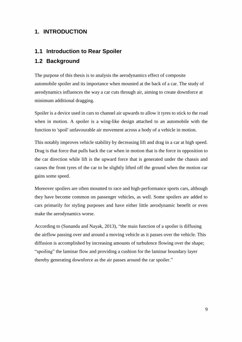
The purpose of this thesis is to analysis the aerodynamics effect of composite
automobile spoiler and its importance when mounted at the back of a car. The study of
aerodynamics influences the way a car cuts through air, aiming to create downforce at
minimum additional dragging.
Spoiler is a device used in cars to channel air upwards to allow it tyres to stick to the road
when in motion. A spoiler is a wing-like design attached to an automobile with the
function to 'spoil' unfavourable air movement across a body of a vehicle in motion.
This notably improves vehicle stability by decreasing lift and drag in a car at high speed.
Drag is that force that pulls back the car when in motion that is the force in opposition to
the car direction while lift is the upward force that is generated under the chassis and
causes the front tyres of the car to be slightly lifted off the ground when the motion car
gains some speed.
Moreover spoilers are often mounted to race and high-performance sports cars, although
they have become common on passenger vehicles, as well. Some spoilers are added to
cars primarily for styling purposes and have either little aerodynamic benefit or even
make the aerodynamics worse.
According to (Sunanda and Nayak, 2013), “the main function of a spoiler is diffusing
the airflow passing over and around a moving vehicle as it passes over the vehicle. This
diffusion is accomplished by increasing amounts of turbulence flowing over the shape;
“spoiling” the laminar flow and providing a cushion for the laminar boundary layer
thereby generating downforce as the air passes around the car spoiler.”

10
However, minimizing the drag caused by turbulence can act to slow the car down. To
create the downforce to the car, the wing operates with air flow at different speeds over
the two sides of the wing, thus creating the pressure difference around the airfoil
contoured shape.
Figure 1. Automobile without and with Spoiler effect (Matt Gartner, 1999, - Aerodynamics)
Considering the left hand side vehicle without the spoiler, as the vehicle accelerates there
is an equal amount of force called drag in the form of air that is in opposition to the
direction of the automobile. This indicates that drag as a force is always present whenever
there is speed. Thus in order to minimize this impedance to a motion car, the engine will
produce more power to overcome the drag force. This results in burning of more fuel as
well as rendering the car to be very lighter at a top speed.
Invariably there is little stability in the motion car, and this can make braking very
difficult as well as negotiating a curve.
Therefore, to minimize the effect of the drag there is a need to create a greater
downforce, thus the introduction of rear spoilers to an automobile, which is shown on
the right hand side of figure 1.
The rear spoiler is designed with the gradual thickness towards the tail edge and this
seeks to disrupt the movement of the air particles. In addition it adds stability to a
motion car as it creates downforce which is a vertical force that acts on the tires causing
traction to the road.
11
In the right hand side of figure 1; the moving air particles are impeded by the rear
spoiler causing the particles to alter their movement. As the impeded air particles gain
momentum the particles gather together and in effect create more force around the boot
of the car; hence the downforce.
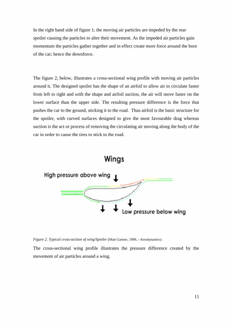
The figure 2, below, illustrates a cross-sectional wing profile with moving air particles
around it. The designed spoiler has the shape of an airfoil to allow air to circulate faster
from left to right and with the shape and airfoil suction, the air will move faster on the
lower surface than the upper side. The resulting pressure difference is the force that
pushes the car to the ground, sticking it to the road. Thus airfoil is the basic structure for
the spoiler, with curved surfaces designed to give the most favourable drag whereas
suction is the act or process of removing the circulating air moving along the body of the
car in order to cause the tires to stick to the road.
Figure 2. Typical cross-section of wing/Spoiler (Matt Gartner, 1999, - Aerodynamics)
The cross-sectional wing profile illustrates the pressure difference created by the
movement of air particles around a wing.
12
1.3 Automated Spoiler
The introduction of automated spoilers has proven helpful as most vehicle spoilers are
designed to disrupt unfavourable air flow in a fixed direction and condition.
A vehicle with a rear spoiler operating in a fixed condition, such as disrupting airflow at
sharp turnings, will not be that efficient when that same vehicle is speeding in a
streamline direction. Thus, the deployment of an automated spoiler is beneficial.
As previously mentioned, airfoils are designed in a wing-like shape with a rounded
leading edge with gradual thickness toward the tail edge. This plays a major role in
creating the pressure difference, as moving air particles travel faster on the lower
surface than the upper side, and thus transit time of particle travel is normally less at the
lower surface as compared to the upper side.
This in effect generates a pressure difference, therefore creating the needed pushing
force called downforce on the automobile which eventually helps to achieve the much
required speed and traction on the tires when the vehicle is in motion.
In an automated spoiler, the position and angle of attack can be altered by increasing the
height of the rear spoiler and introducing the extra bracket structures with hinges in
order to retract and adjust the automated spoiler.
A vehicle’s automated rear spoiler comprises of at least one airfoil with elongated
leading and trailing edge to provide the effective drag needed. The actuators can be
retracted linearly to provide different positions to the airfoil.
The purpose of a controlled braking system is to detect events associated with the
braking of the vehicle, and sensors to aid in the steering wheel system and the
movement of the rear spoiler can be either automatically or manually operated.
13
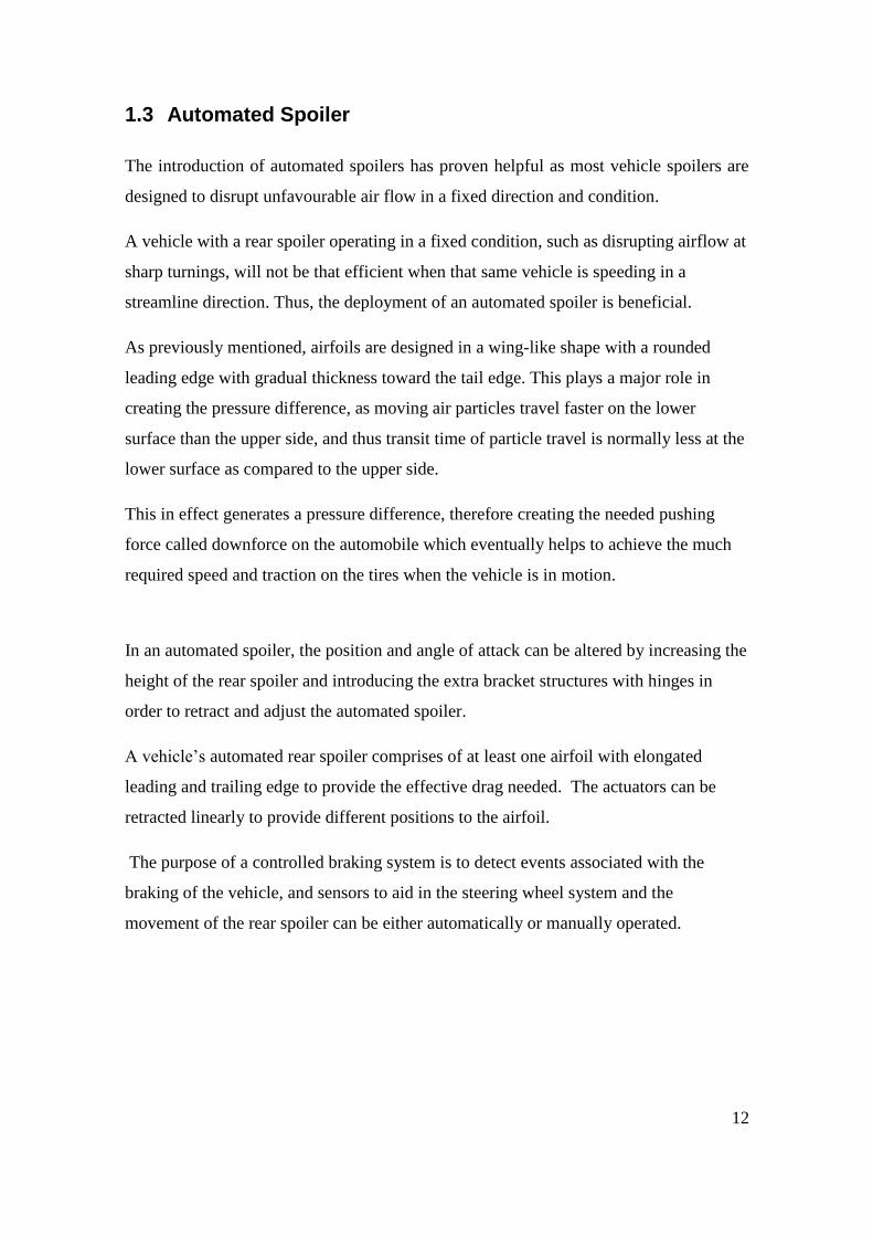
Figure 3. A Typical Airfoil Wing with Angle of Attack. (Chang, 1998.)
Figure 3, shows a well labelled airfoil which is a cross-section of the spoiler/wing with
an angle of attack and the shape of the wing is varied along the blade radius to take
advantage of airspeed around both of the upper and lower camber.
The chord line is an imaginary straight line through the spoiler/wing which connects the
leading and trailing edges of the airfoil, whereas the chord length is the imaginary
straight line from the leading edge to the trailing edge. It is measured as the
longitudinal dimension of the spoiler.
The curvature of the spoiler is referred to as a camber, and the trailing edge is the back
portion of the airfoil where the air flowing over both the upper and lower camber meets.
The leading edge is that part of the airfoil where the air flow starts. Its shape determine
the speed of the airfoil as an airfoil designed to operate at high speed will have very
sharp leading edge to easily transport the flowing air particles the moment they hit the
edge.
The angle of attack is the relation between the “chord” of the spoiler/wing and the
vector created with the direction of the air flowing over the spoiler. It can be noted that
as the angle of attack increases the dragging force will eventually increase and this will
serve as impedance to an accelerated car.
14
Therefore, an automated spoiler can play a major effect to minimize the dragging force
as it can be tilted to a desirable angle to generate more “spoiling” at extremely high
speed. This will create a greater downforce which will in effect minimize the drag force.
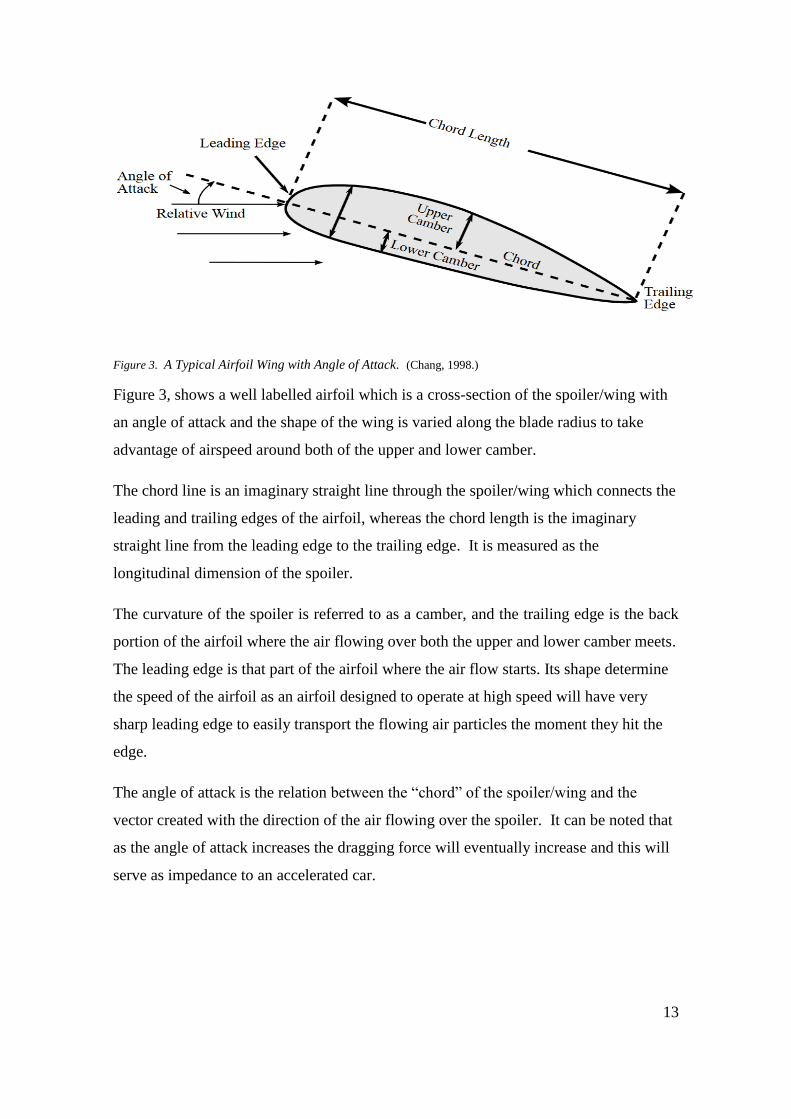
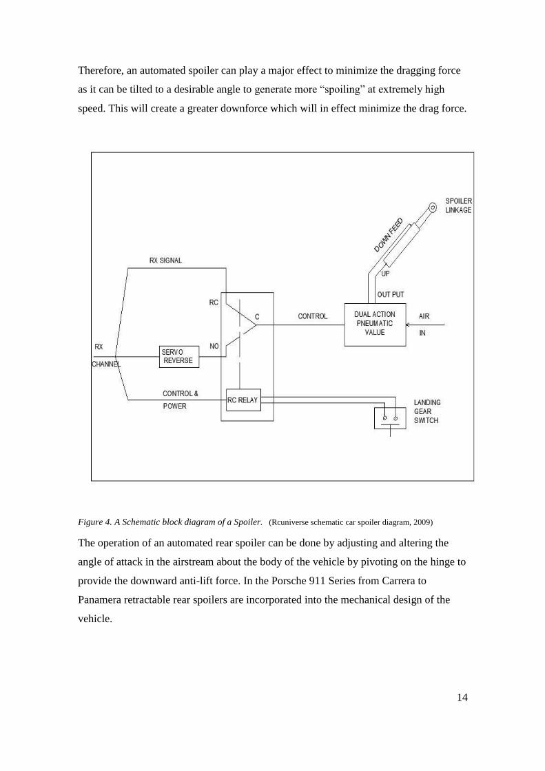
Figure 4. A Schematic block diagram of a Spoiler. (Rcuniverse schematic car spoiler diagram, 2009)
The operation of an automated rear spoiler can be done by adjusting and altering the
angle of attack in the airstream about the body of the vehicle by pivoting on the hinge to
provide the downward anti-lift force. In the Porsche 911 Series from Carrera to
Panamera retractable rear spoilers are incorporated into the mechanical design of the
vehicle.
15
It can be noted that if the rear spoiler cannot be extended in the Porsche 911 Carrera,
driving stability will be adversely affected by the increased rear axle lift, which could
lead to loss of control.
The 2012 Porsche 911 series in its automated mode and depending on the vehicle speed
and position of the tilt roof, the rear spoiler can be extended automatically at above
approximately 75mph (120km/h) and can eventually retract again at approximately
50mph (80km/h).
This is achieved by selecting the desired anti-lift that is the downward forces on the
spoiler, an actuator in a form of a hydraulic cylinder and piston is mounted and this
connection is control by a foot pedal or a bottom press. The actuator uses a
servomechanism, as shown in the figure 4 as the servo reverse is an automatic device that
gives feedback or error-correction signals of the input signal. It is measured by a
transducer which is a device that converts the input pressure into electrical signals and
thus the servo device compares the actual input with the received signal and with the help
of the control and power chamber the unwanted signal is used to drive the system in the
direction necessary to reduce or cancel the error.
The spoiler has column pivot pins, which are located at the centre so that the presence of
a relative moving airstream forces the spoiler to assume a high negative angle of attack.
This causes the spoiler to obtain a frontal profile shade to the airstream causing it to
experience downwards and rearwards direct aerodynamic forces. This enhances traction
on the wheels.
However, it is also designed to lessen or remove the anti-lift forces as the actuator can
be pressurized to force the leading edges upward about their pivot pins. This invariably
reduces the negative angle of attack and therefore the spoiler retracts to zero angle of
the angle of attack to the airstream.
16
The retractable rear spoiler of the Porsche series improves the driving stability at high
speeds and reduces fuel consumption at low speeds. However, vehicles with turbo engines
have an enhanced rear spoiler with a larger and more effective spoiler surface due to
additional flaps to improve the aerodynamics.
There are a few different spoilers positioned at strategic places on an automobile all
serving specific purposes.
The pedestal spoilers are those actually with aerodynamic enhancers, which create the
essential amount of downforce on the vehicle when mounted to the boot. These types of
spoilers disrupt the aerodynamic drag and give better fuel economy and performance.
It is more or less of the same width as the vehicle’s boot; and anchored at 2 or 4 points
when fixed at the rear end of the boot.
1.4 Objectives
There are 3 objectives which this thesis seeks to fulfill;
Describe rear spoilers’ geometry with respect to its desired function in a car.
Explore design alternatives that are manufacturable for composite materials.
Apply Finite Element Analysis Methods (FEM) to spoiler structural design.

17
2. METHOD
2.1 PROCESS REVIEW FOR REAR CAR SPOILER
There are enormous traditional manufacturing processes used in the production of car
spoilers. Some of these methods are hand layup molding, vacuum bag molding and
spray-up. Thus in making a part there are three main considerations which are:
Cost Estimation
Raw Material
Method
Thus depending on the manufacturing process chosen, a suitable raw material is
selected such as fiberglass, and laid on the tool/mould. Afterwards, heat and pressure is
applied to transform the raw materials into the finished or final product in the case the
spoiler.
2.2 Cost Estimation
The cost of production in the automobile industry is very expensive which implies that
producing a part like a spoiler with a composite may be costly; however most costumers
in the automobile market are cost sensitive. Therefore the best suitable production
methods are used to produce affordable spoilers of good quality and functional
composite materials.
The factors that influence cost is raw materials, process cycle time and assembly part.
The cost of the product depends also on the volume of production.
Thus cost estimation is a very essential element in manufacturing a product at low cost.
This has significant impact on the market as in the area of composite materials the
product must compete with well-developed traditional materials such as metal
technologies.
18
Therefore, in selecting the right manufacturing processes the relationship between the
production volume rate and product cost should be completely analyzed.
Cost estimation is done to predict the cost of the product and to provide a quotation or
to establish the selling price. This also enables the engineer to compare other design
alternatives.
It is also useful to compare cost of materials, labour, equipment and methods between
various manufacturing options, as a well detailed specification of the spoiler product
must include the type of fiber and matrix materials, the fiber orientation and the
fabrication method to be used.
In addition, the cost of the product relies deeply on a good estimate which includes
parameters such as detailed product drawing that is a well- sketched drawing as well as
equipment and accessory requirements.
A good knowledge of the process cycle time and processing requirement is vital to give
an insight of the production rate which must eventually allow for enough timing for
packaging and delivery schedules.
2.3 Raw Materials for Composite Manufacturing Processes
Raw materials use in composite manufacturing processes can be categorized into two
main parts. These are thermoset-based and thermoplastic-based composite materials.
Thermoplastics are those materials that can be reshaped or remelted once they have
solidified whereas thermoset plastics cannot be remelted once cured.
Thermoset and thermoplastics each have their own advantages and disadvantages in
terms of cost, processing, recyclability, performance and storage.
Thus some materials are best suited for specific manufacturing methods especially in
part fabrications for example injection molding processes utilizes pellets, while a
filament winding uses continuous fibers and wet resin systems in most processes.
Composite systems are made of two main constituents and these are reinforcements and
resins matrix.
19
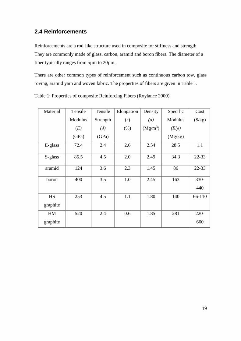
2.4 Reinforcements
Reinforcements are a rod-like structure used in composite for stiffness and strength.
They are commonly made of glass, carbon, aramid and boron fibers. The diameter of a
fiber typically ranges from 5µm to 20µm.
There are other common types of reinforcement such as continuous carbon tow, glass
roving, aramid yarn and woven fabric. The properties of fibers are given in Table 1.
Table 1: Properties of composite Reinforcing Fibers (Roylance 2000)
Material Tensile
Modulus
(E)
(GPa)
Tensile
Strength
(δ)
(GPa)
Elongation
(ϵ)
(%)
Density
(ρ)
(Mg/m3)
Specific
Modulus
(E/ρ)
(Mg/kg)
Cost
($/kg)
E-glass 72.4 2.4 2.6 2.54 28.5 1.1
S-glass 85.5 4.5 2.0 2.49 34.3 22-33
aramid 124 3.6 2.3 1.45 86 22-33
boron 400 3.5 1.0 2.45 163 330-
440
HS
graphite
253 4.5 1.1 1.80 140 66-110
HM
graphite
520 2.4 0.6 1.85 281 220-
660
20
2.5 Polymer Matrix Selection
Matrix selection is practically base on thermal properties, cost, availability,
environmental and health concerns and ability to process the material.
Matrix of composite functions as a binder transferring load through the fiber network
thereby maintaining the fiber orientation and protecting the individual strands when
there is a fiber break.
When selecting a resin; the essential consideration should be the stiffness (elastic
modulus) and the yield and ultimate strength as well as the toughness properties.
The two main polymer resin systems used in the automobile industries are thermoset
and thermoplastics. In structural composite applications where good mechanical and
thermal properties as well as good bonding to reinforcement is required with easy
processing, low cost and low viscosity thermoset polymers dominate.
Thermoplastics exhibits high viscosity and poor bonding. However, it is efficiently used
in areas where toughness, low volatile emissions and recyclability are essential.
Resin selection involves several factors. For instance in choosing a specific resin the
following chemical characteristics should be considered; resin viscosity, glass transition
temperature, gel time, cure time, injection, thermal stability, environmental resistance
and volatile emission during processing in order to obtain optimum functionality of that
particular resin.
The mechanical properties that should be essentially considered when selecting the
matrix are interlaminar fracture toughness, strength and elastic modulus in certain
directions as well as environmental resistance.
Epoxies, polyesters and vinyl esters are thermoset resins commonly used in composite
manufacturing because they offer satisfactory impregnation of reinforcing fibers such as
fiber glass, carbon fiber or Kevlar during working processes when used as resins.
21
2.6 Matrix Materials
As was previously discussed, composites are made of reinforcing fibers and matrix
materials. The matrix surrounds the fibers and enables the fibers to carry maximum load
with lower modulus and greater elongation.
Matrix selection should be based on chemical, thermal, electrical, flammability, cost,
environmental, performance and manufacturing requirements. The matrix determines the
working operating temperature of the composite and the manufacturing processing.
2.7 Epoxy
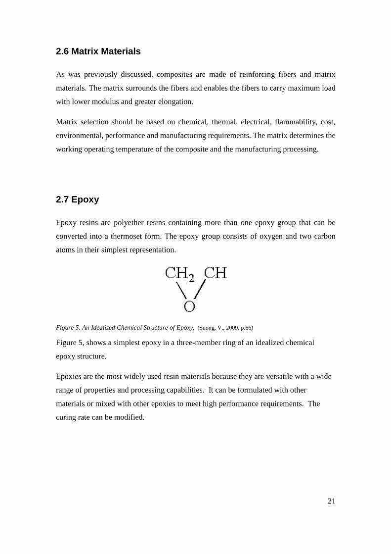
Epoxy resins are polyether resins containing more than one epoxy group that can be
converted into a thermoset form. The epoxy group consists of oxygen and two carbon
atoms in their simplest representation.
Figure 5. An Idealized Chemical Structure of Epoxy. (Suong, V., 2009, p.66)
Figure 5, shows a simplest epoxy in a three-member ring of an idealized chemical
epoxy structure.
Epoxies are the most widely used resin materials because they are versatile with a wide
range of properties and processing capabilities. It can be formulated with other
materials or mixed with other epoxies to meet high performance requirements. The
curing rate can be modified.
22
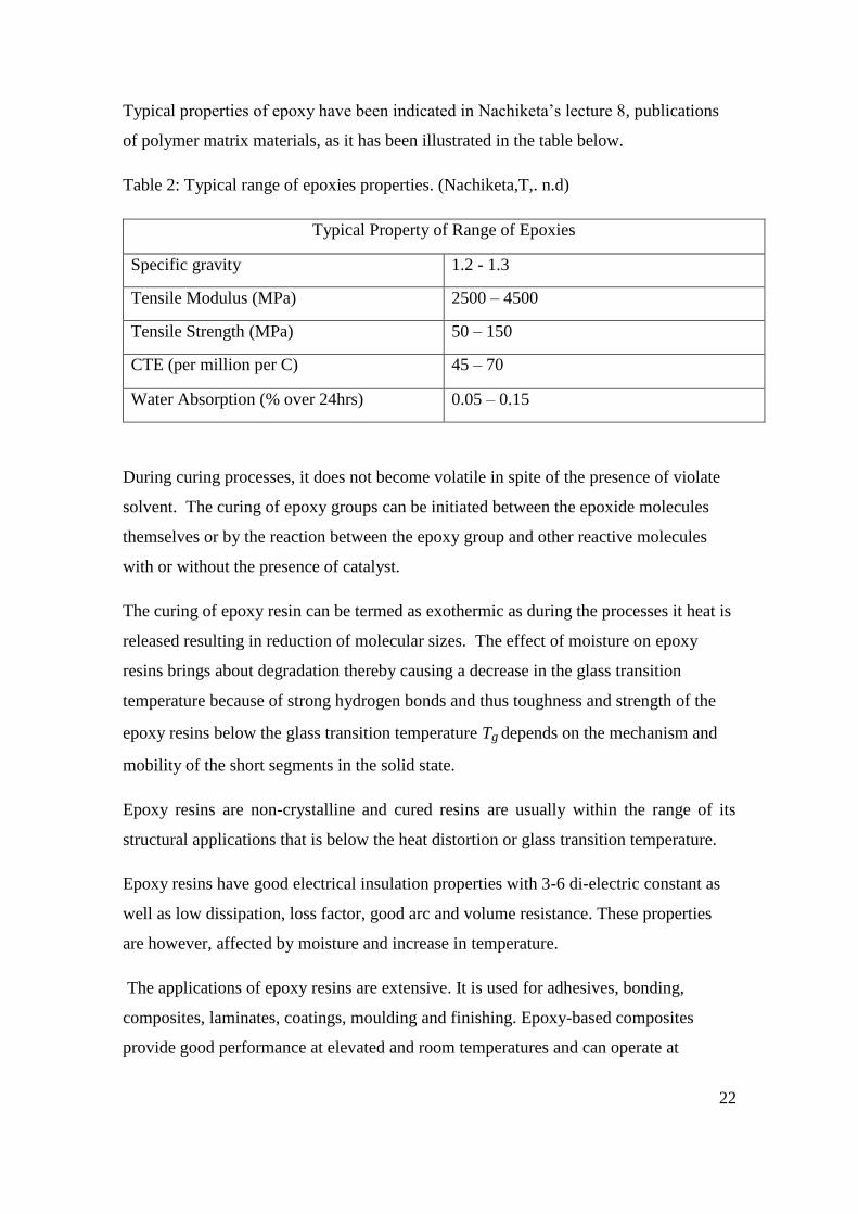
Typical properties of epoxy have been indicated in Nachiketa’s lecture 8, publications
of polymer matrix materials, as it has been illustrated in the table below.
Table 2: Typical range of epoxies properties. (Nachiketa,T,. n.d)
Typical Property of Range of Epoxies
Specific gravity 1.2 - 1.3
Tensile Modulus (MPa) 2500 – 4500
Tensile Strength (MPa) 50 – 150
CTE (per million per C) 45 – 70
Water Absorption (% over 24hrs) 0.05 – 0.15
During curing processes, it does not become volatile in spite of the presence of violate
solvent. The curing of epoxy groups can be initiated between the epoxide molecules
themselves or by the reaction between the epoxy group and other reactive molecules
with or without the presence of catalyst.
The curing of epoxy resin can be termed as exothermic as during the processes it heat is
released resulting in reduction of molecular sizes. The effect of moisture on epoxy
resins brings about degradation thereby causing a decrease in the glass transition
temperature because of strong hydrogen bonds and thus toughness and strength of the
epoxy resins below the glass transition temperature Tg depends on the mechanism and
mobility of the short segments in the solid state.
Epoxy resins are non-crystalline and cured resins are usually within the range of its
structural applications that is below the heat distortion or glass transition temperature.
Epoxy resins have good electrical insulation properties with 3-6 di-electric constant as
well as low dissipation, loss factor, good arc and volume resistance. These properties
are however, affected by moisture and increase in temperature.
The applications of epoxy resins are extensive. It is used for adhesives, bonding,
composites, laminates, coatings, moulding and finishing. Epoxy-based composites
provide good performance at elevated and room temperatures and can operate at
23
temperatures of around 90 to 120 °C. Epoxies come in various forms such as liquid,
solid and semi-solid forms.
The liquid epoxies are used in manufacturing processes such as filament winding,
pultrusion, hand lay-up and processes with various reinforcing fibers such as glass,
carbon, aramid boron etc. Epoxies are generally brittle but are toughened by adding
thermoplastics, and it is more costly than vinyl esters and polyesters.
2.8 Polyesters
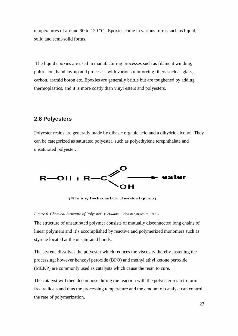
Polyester resins are generally made by dibasic organic acid and a dihydric alcohol. They
can be categorized as saturated polyester, such as polyethylene terephthalate and
unsaturated polyester.
Figure 6. Chemical Structure of Polyester. (Schwartz –Polyester structure, 1996)
The structure of unsaturated polymer consists of mutually disconnected long chains of
linear polymers and it’s accomplished by reactive and polymerized monomers such as
styrene located at the unsaturated bonds.
The styrene dissolves the polyester which reduces the viscosity thereby fastening the
processing; however benzoyl peroxide (BPO) and methyl ethyl ketone peroxide
(MEKP) are commonly used as catalysts which cause the resin to cure.
The catalyst will then decompose during the reaction with the polyester resin to form
free radicals and thus the processing temperature and the amount of catalyst can control
the rate of polymerization.

24
The higher the temperature or the more the catalyst, the faster the reaction is. When the
resin turns from liquid to brittle solid, a post cure at a higher temperature may be
needed, as post cure increases transition temperature Tg of the resin by complete cross-
linking.
Orthophthalic polyesters are environmentally sensitive and have limited mechanical
properties but isophthalic polyesters have excellent environment resistance and
improved mechanical properties.
Table 3: General properties of thermoset polyester. (Nachiketa, T., n.d)
Commonly Used Properties of Thermoset Polyester
Specific gravity 1.1 – 1.4
Tensile Modulus (MPa) 2000 – 4400
Tensile Strength (MPa) 33-104
CTE (per million per C) 55 – 100
Water Absorption (% over 24hrs) 0.15 – 0.65
Polyesters offer excellent corrosive resistance and are low-cost resins and also the
workable temperatures for them are lower than epoxies. They can be thermosetting or
thermoplastic resin and are widely used in manufacturing processes such as filament
winding, pultrusion etc.
Unsaturated polyesters can be obtained through the reaction of unsaturated di-functional
organic acids with di-functional alcohol. During the curing or cross-linking process the
carbon-carbon double bonds in the unsaturated polyester molecules and an addictive
such as styrene molecules forms the cross-linking site, thus, reactive monomers such as
styrene is added in ranges of 30 to 50 wt%. Otherwise the use of styrene in polyester is
been reduce due to growing health concerns.
25
2.9 Vinyl esters
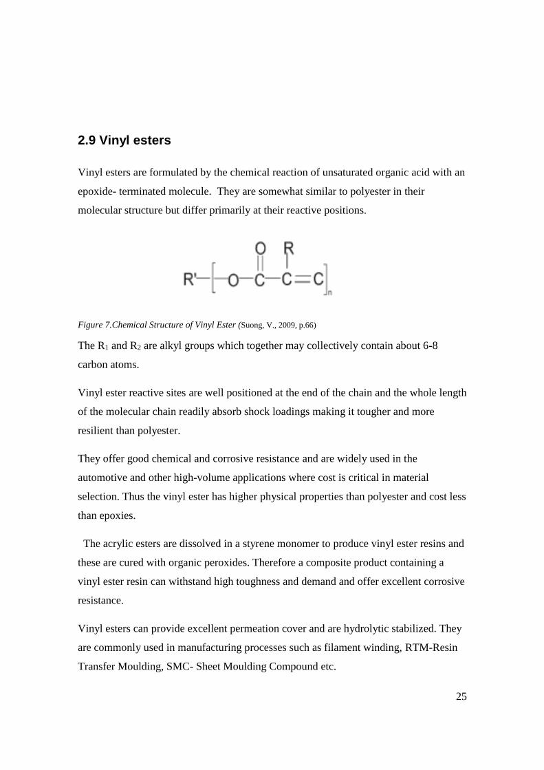
Vinyl esters are formulated by the chemical reaction of unsaturated organic acid with an
epoxide- terminated molecule. They are somewhat similar to polyester in their
molecular structure but differ primarily at their reactive positions.
Figure 7.Chemical Structure of Vinyl Ester (Suong, V., 2009, p.66)
The R1 and R2 are alkyl groups which together may collectively contain about 6-8
carbon atoms.
Vinyl ester reactive sites are well positioned at the end of the chain and the whole length
of the molecular chain readily absorb shock loadings making it tougher and more
resilient than polyester.
They offer good chemical and corrosive resistance and are widely used in the
automotive and other high-volume applications where cost is critical in material
selection. Thus the vinyl ester has higher physical properties than polyester and cost less
than epoxies.
The acrylic esters are dissolved in a styrene monomer to produce vinyl ester resins and
these are cured with organic peroxides. Therefore a composite product containing a
vinyl ester resin can withstand high toughness and demand and offer excellent corrosive
resistance.
Vinyl esters can provide excellent permeation cover and are hydrolytic stabilized. They
are commonly used in manufacturing processes such as filament winding, RTM-Resin
Transfer Moulding, SMC- Sheet Moulding Compound etc.
26
A cured vinyl ester provides increased ductility and toughness because in vinyl ester
molecules, there are fewer unsaturated sites for cross-linking than in polyester or
epoxies.
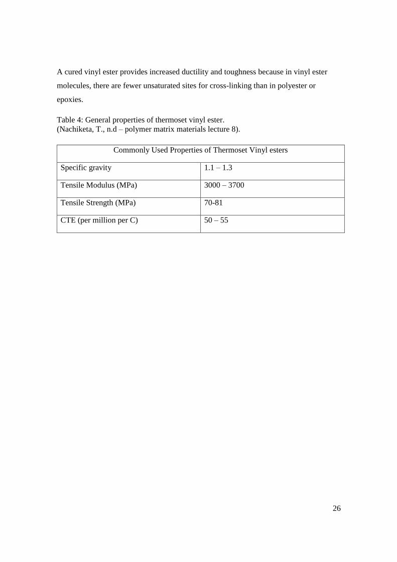
Table 4: General properties of thermoset vinyl ester.
(Nachiketa, T., n.d – polymer matrix materials lecture 8).
Commonly Used Properties of Thermoset Vinyl esters
Specific gravity 1.1 – 1.3
Tensile Modulus (MPa) 3000 – 3700
Tensile Strength (MPa) 70-81
CTE (per million per C) 50 – 55
27
3. MANUFACTURING PROCESSES
3.1 Hand lay-up Molding
Hand lay-up is one of the oldest dominant open molding techniques used in making the
composite fabrication parts such as spoilers. It is labour intensive method which
involves using reinforcing materials which are often in the form of chopped strand mat
or aligned fabric such as woven rovings. Epoxy, polyester and vinyl ester resins are
mostly used in these processes.
They are positioned manually in a single sided female mould with the application of
liquid resin inside the mold and the reinforcement placed on top.
A reinforcement material is the part of a composite that provides the desired stiffness,
strength and the ability to withstand applied load.
Trapped air is then steadily removed by manually applying rollers to complete the
laminate structure. This work is often done under room temperature for effective and
efficient curing.
3.1.1 Making of the Part
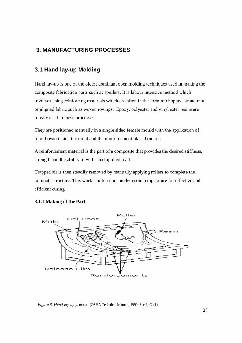
Figure 8. Hand lay-up process. (OSHA Technical Manual, 1999. Sec.3, Ch.1).
28
A schematic diagram of the hand lay-up process is shown in Figure 8, where the
composite part is moulded by applying reinforcing layers and liquid resin and a roller to
evenly distribute the resin completely on the surface and to remove trapped air before
the release film is applied.
3.1.2 Method of Applying Heat and Pressure
As mentioned previously, the process is done under room temperature conditions. The
resin is often left at that temperature for a day for complete curing but the curing time
can be shortened by blowing warm air on the laminate, using the roller is use to apply
pressure on it and the use of gel coat as a hardener.
3.1.3 Basic Processing Steps
The basic and main processing steps use in hand lay-up to obtain an acceptable surface
finish greatly involves the use of release agent which provides easier removal of part
during the time of demoulding and notably insufficient application of release agent will
render some part sticking inside the mold.
The gel coat is applied to create finished surface and it is allow hardening sufficiently
before reinforcing layers are placed in one at a time. The reinforcement layers placed on
the mould surface are wet with catalyzed resin and evenly distributed by the help of a
roller or brush. Afterwards the final part is allowed to cure at room or elevated
temperature.

29
3.1.4 Merits of Hand Lay-Up Process
The hand lay-up processes have some few advantages as the product produce is mostly
simple and versatile with its fiber orientation and the equipment cost is nearly negligible.
This is suitable for low volume manufacturing and very low capital investment is
involved.
3.1.5 Limitations of Hand Lay-Up Process
The major limitations of hand lay-up methods are that the process is labour intensive
and needs much skilled work in order to obtain a quality final part. The quality of the
finished part is mostly not constituent because of the lack of direct control over the part
thickness, fiber content which implies that high fiber volume fraction cannot be
manufactured with this process and there is dimension inaccuracy in producing the part.
3.2 Spray-Up Process
Spray-Up is another form of open mould method similar to the hand lay-up but the
difference is the way and manner the fibers and the resin materials are applied onto the
mould. A spray- gun is used to apply the resin and reinforcement in this process unlike
the roller used in hand lay up process.
This method deploys the used of chopped fiberglass reinforcement and catalyzed resin,
which are applied onto the mould. The spray-gun simultaneously chops continuous fiber
roving in a predetermined length of 10 to 40mm and impresses it through a catalyzed
resin onto the mould. The spray-up process is much faster than the hand lay up and a
less expensive choice when using rovings. Work is done at room temperature for curing.
30
3.2.1 Making of the Part
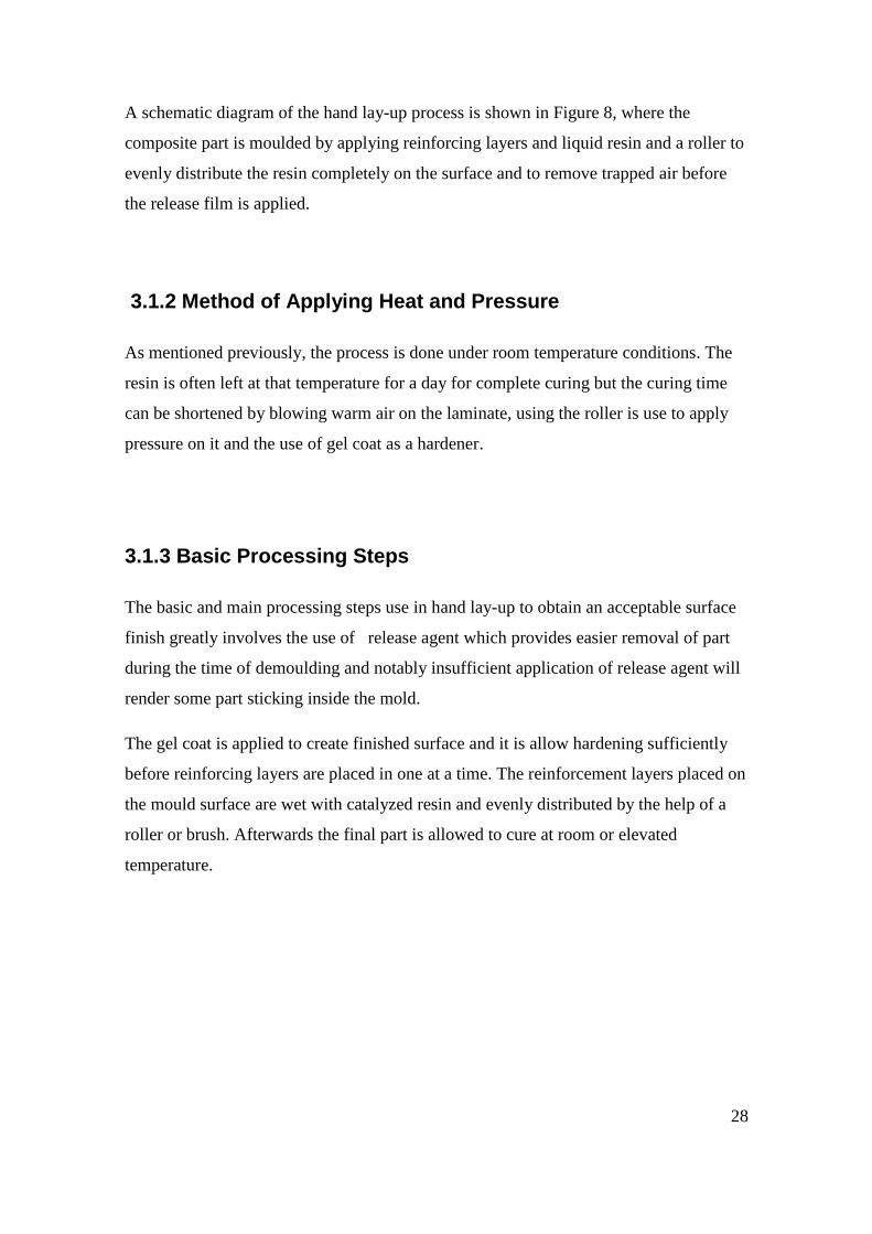
Figure 9. Spray- up Molding Processes. (Lecture 5.4: Hand lay- up and Spray lay- up)
In this process, the release agent is first applied to the mould and then after, it the gel
coat. The gel coat is left for a few hours, often 2 hours, until it hardens. Then the spray-
gun is used to deposit the fiber resin mixture onto the surface of the prepared mould.
In this process the thickness obtained depends on the pattern of the spraying. Next,
rollers or brushes are used to remove entrapped air as well as ensure good fiber wetting
and then curing is allowed to take place at room temperature.
3.2.2 Basic Processing Steps
The basic steps of a spray- up process involve the use of wax and polish on the mould to
allow for easy demoulding. The gel coat is applied to the mould surface, and is allowed
to sufficiently harden before the laying of the fiber materials.
Another coat applied is the barrier coat which is placed in an oven to prevent fiber
imprint through the gel coat during curing and most often the laminate is put in an oven
to cure.
31
3.2.3 Merits of Spray lay–Up Process
The advantages spray-up offers during its processing are enormous as compared to the
hand lay-up methods. This technique is suitable for small-to-medium –volume parts
manufacturing with low-cost materials and this eventually uses less expensive tooling.
3.2.4 Limitations of Spray lay-Up Process
The finished part mostly have good surface at one side whereas the other side is
somewhat rough, and it not ideal to use this method for making parts with high
structural requirements. In this method controlling the fiber volume fraction as well as
the thickness is difficult.

32
4. THEORY OF SPOILER
This chapter deals with the concept of aerodynamics of the spoiler and continues with
the analysis of the design of the spoiler. NASTRAN is used to study the static load
analysis when uniform load is applied on the spoiler.
4.1 History of Spoilers
Spoilers were first introduced on vehicles in the late 1960’s and were experimented
with in racing cars. Spoilers became popular with motorsport vehicles in the 1970’s and
also started to appear regularly on modern passenger automobiles as there was an aim to
reduce drag and improve fuel efficiency at accelerated speeds.
The effect of aerodynamics on a vehicle is summarized in terms of drag, downforce and
stability. Automobile manufacturers realized that vehicle stability can be improved by
balancing the downforce and creating more traction on the tires whereas the weight of
the car is unchanged.
Formula One racing cars considered the use of spoilers to produce downforce to the cars
which can be likened to a virtual increase in weight as it presses the car to the road and
causes swiftness when negotiating a curve as well as increasing frictional force on the
road.
Apparently, the motion of air around an object enables the calculation of forces acting on
the object. Velocity, pressure, density and temperature as a function of position and time
are mostly the properties calculated.
A control volume around the flow field is mostly defined, equations for the conservation
of mass, momentum and energy can be defined and used to solve for the properties.
(Karman, 2004).
33
Nowadays, improved spoilers shapes and the study of aeronautic technology has
considerably helped vehicle stability, and the use of light weight but strong materials to
manufacture spoilers and automobiles parts have drastically enhance vehicle
aerodynamics.
4.2 Design of a Rear Spoiler/Wing
In the process of designing a rear car spoiler, rules governing the specifications and
requirements must be considered in order to achieve the optimum design objectives to
efficiently minimize drag on an automotive vehicle.
The rear spoiler design requirements that need to be taken into consideration are
performance in that the spoiler should be able to minimize drag, stability and control
whereby the vehicle can stay grounded with the tires on the road at accelerated speed.
The rear spoiler should be a cost effectively producible design and also be easily
operated if it is an automatic spoiler.
The spoiler or wing must be oriented in a plane view with the quadrilateral defining the
outside of the tires on the sides of the vehicle by a transverse line of 460 mm between
the rears of the rear tires. The spoiler should be mounted in a suitable position so that it
does not block the driver’s egress or exit.
In the design geometry, the leading edges of the rear spoiler or wing should be of a
12.7mm minimum radius and it must be blunt or blunter than the required radii for an
arc of plus or minus 45 degrees centered on the plane parallel to the ground.
The spoiler or wing edges must have minimum edge radii of at least 3mm that is a 6mm
thick edge at least. When setting up a wing for an automobile vehicle, first the
theoretical top velocity of air flowing on top of the trunk of the vehicle without wing
and the top speed must be anticipated. Airflow velocity when the wing is mounted on
the vehicle should also be calculated. This will assist the designer to decide on how best
to knock off that top speed by the addition of the spoiler.

34
The calculated difference between the top speed with and without the spoiler obtained
will be donated as the downforce. Thus, relatively small changes added to the rear wing
configuration alter the downforce and also improve the vehicle’s drag figure with a big
difference.
4.3 The Airfoil Selection Process
The best form of airfoil selection is by initially considering the weight of the
spoiler/wing because it is best to avoid adding unwanted weight to the automobile
vehicle.
In table 4 below, illustrates the weight distribution over quantities relevant in obtaining
optimum wing design.
Table 5: Illustrates a sample of airfoil weight distribution selection. (Sadraey, 2013).
Design Objective Weight (%)
Stability Requirement 20
Control Requirement 15
Cost Requirement 10
Producibility Requirement 10
Operational Requirement 40
Other Requirement 5
Summation 100
The spoiler is designed with a cross-section called airfoil and its main function is the
generation of optimum pressure distribution on both sides of the spoiler, meaning the
top and bottom surfaces.
One of the wing parameters that must be considered in the wing design process is the
position of the wing’s vertical location relative to the trunk of the vehicle and its
alignment with the body of the automobile.

35
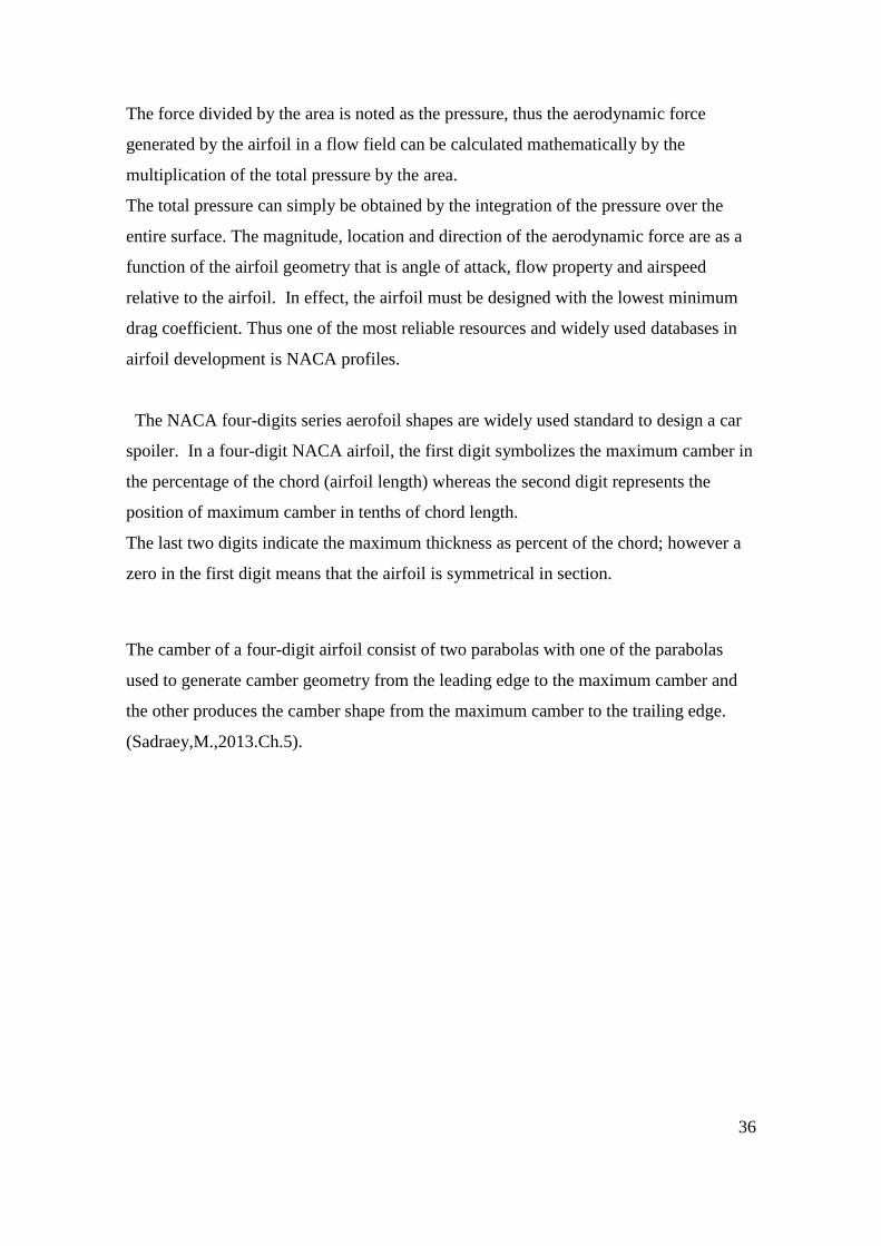
A typical airfoil section is shown below in figure 10, where several geometric
parameters are illustrated. The airfoil is referred to as symmetrical if the mean camber
line is in a straight line, otherwise it is known as cambered airfoil.
The camber of an airfoil is normally positive and the angle of attack increases with the
pressure difference between the upper and lower surfaces as it is illustrated in figure 11.
(Sadraey,M., 2013.Ch.5).
Figure 10. The geometric parameters of airfoil
Figure 11. The flow around an Airfoil
36
The force divided by the area is noted as the pressure, thus the aerodynamic force
generated by the airfoil in a flow field can be calculated mathematically by the
multiplication of the total pressure by the area.
The total pressure can simply be obtained by the integration of the pressure over the
entire surface. The magnitude, location and direction of the aerodynamic force are as a
function of the airfoil geometry that is angle of attack, flow property and airspeed
relative to the airfoil. In effect, the airfoil must be designed with the lowest minimum
drag coefficient. Thus one of the most reliable resources and widely used databases in
airfoil development is NACA profiles.
The NACA four-digits series aerofoil shapes are widely used standard to design a car
spoiler. In a four-digit NACA airfoil, the first digit symbolizes the maximum camber in
the percentage of the chord (airfoil length) whereas the second digit represents the
position of maximum camber in tenths of chord length.
The last two digits indicate the maximum thickness as percent of the chord; however a
zero in the first digit means that the airfoil is symmetrical in section.
The camber of a four-digit airfoil consist of two parabolas with one of the parabolas
used to generate camber geometry from the leading edge to the maximum camber and
the other produces the camber shape from the maximum camber to the trailing edge.
(Sadraey,M.,2013.Ch.5).
37
Figure 12. Sample of Airfoil Section
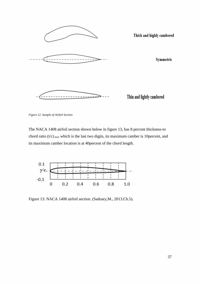
The NACA 1408 airfoil section shown below in figure 13, has 8 percent thickness-to
chord ratio (t/c) max which is the last two digits, its maximum camber is 10percent, and
its maximum camber location is at 40percent of the chord length.
Figure 13: NACA 1408 airfoil section. (Sadraey,M., 2013.Ch.5).
38
4.4 Drag
According to (Steven. D.G, 2009) the definition of drag is: “Drag is the aerodynamic
force that is in opposition to the velocity of an object moving through air or fluid. It is
directly proportional to the speed differential between air and the solid object.
Drag comes in various forms; frictional drag is as a result of the friction of the solid
molecules against air molecules in their boundary layer.
Friction and its drag depend on the fluid and the solid properties because a smooth
surface of the solid for example produces less skin friction compared to a rough one.
Friction varies with its viscosity along with airflow and the relative magnitude of the
viscous forces to the movement of the flow; this is expressed as the Reynolds number.
Low energy flow generated along the solid surface depends on the magnitude of the
skin friction and conditions in the boundary layer.
Thus, the form of drag is dependent on the particular shape of a wing profile.
The changes in air pressure and the velocity of the motion air flowing around the spoiler
effectively create the required force to enable traction on the tires to the road.
Induced drag or interference drag is a result of vortices that are generated behind the
solid object due to the change of the direction of the air around the spoiler.
A vortex is considered the region within fluid mechanics where the flow is mostly in a
spinning motion.”
39
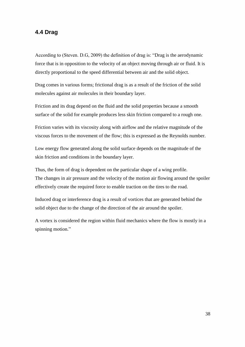
Figure 14. Type of drag co-efficient Cd (Steven. D.G 2009)
Thus, the amount of drag that is induced as the automobile motions can be quantified as
drag coefficient. This coefficient is expressed as the ratio of the drag force to that of the
force induced by the dynamic pressure times the area whereas at relatively high speeds
of high Reynolds number (Re > 1000), the aerodynamic drag force can be calculated as:
Fd = 1
2ρ υ2A cd [Eq.1]
Where
Fd = Force of drag
ρ = Density of the air
V2 = Speed of the object relative to the fluid (m/s)
A = Reference surface Area
Cd = coefficient Drag
The above formula indicates that aerodynamic drag increases with the square of the
speed.
40
The drag co-efficient formula can be derived from Daniel Bernoulli’s equation for
pressure in a fluid which is given as:-
P1 + ρgy1+1/2ρυ12= P2 + ρgy2+1/2ρυ2
2 [Eq. 2]
The first term on either side of the equation is referred to as atmospheric pressure which
is observed as outside pressure of the fluid content whereas the second term is the
gravitational force which causes buoyancy.
The third term is the kinetic or dynamic contribution to the pressure been experienced,
which is related to the flow and relevant to the derivation of the Drag Force.
P = 𝐹
𝐴 [Eq. 3]
⇒ F = P𝐴 [Eq. 4]
Therefore, in Bernoulli’s equation the pressure, P = 1
2𝜌𝜐2 [Eq. 5]
Inserting equation 4 into 5 gives Fd=1
2𝜌𝜐2𝐴𝐶 [Eq. 6]
In equation 6, there is an additional factor that is the symbol C, which is the coefficient
of drag, which implies drag, is influenced by factors such viscosity, texture and shape
which results in viscous drag and skin friction.
Thus viscous drag is observed in a laminar flow when fluids flow around an obstacle; it
exerts a viscous drag on the obstacle whereas skin friction is the resistance around the
surface of the spoiler encounter by a moving air.
Therefore, it can be deduced that drag is directly proportional to density and the area but
there is always a resistive force with a moving vehicle, which implies that the more the
acceleration the greater the resistive force. Thus from the Bernoulli’s equation it is the
square of the velocity. It can clearly be concluded that drag is related to speed by some
form of a polynomial. (Glenn, 2014)

41
4.5 Downforce
Sir Isaac Newton in 1686; Energy is constant in a closed system, even though it can be
converted from one form to another. Thus out of this theory, Daniel Bernoulli deduced
a formula proving that the total energy in a steadily flowing fluid system is a constant
along the flow path.
An increase in fluid’s speed must be aligned by decrease in its pressure. Adding up the
pressure variation multiplied by the area around the entire body determines the
aerodynamic force on the body. (Steven D.G 2009).
Figure 15. Aerodynamic downforce (Kasravi, n.d vehicle aerodynamics)
An aerofoil’s operation is better explained with a wing/spoiler in a steady laminar flow
of air. Spoilers are designed with more thickness at one end and thus molecular free air
moves around with different speed at different locations in airstreams.
Therefore, increasing the flow speed and decreasing the pressure would slightly reduce
the airstream on the lower surface. The pressure difference will generate a downward
force on the wing due to the lower airspeed on top of the spoiler.
The wing is designed with contour shape to induce a new turning of the airflow creating
the downforce. (Steven. D.G, 2009).
42
However, the air on the longer side of the wing will flow much faster, further increasing
the downforce effect. The simultaneous conservation of mass, momentum and energy of
a fluid (while neglecting the effects of air viscosity) are termed the Euler Equations
named after Leonard Euler. (Steven.D.G, 2009).
4.6 Flows: Laminar and Turbulent
When a vehicle moves through still air, its shape disturbs the air particles such that their
velocity is not equal at all positions in the flow. If the air particles travel in “well
organized” parallel lines then this is known as laminar. On the other hand it is possible
to have the same average speed in the flow, but eventually the average speed of the fluid
particles will momentarily move in the a disorder /opposite direction along the spoiler.
The fluid in this behavioral manner is called turbulent, even though the average velocity
could be the same in both the laminar and turbulent flows.
It is essential to know the type of flow being dealt with, whether it is laminar and
turbulent, since features such as flow separation and vehicle drag can change
dramatically between these two flows.
In “Race car Aerodynamics” normally when an automobile travels in an undisturbed
environment, the prevailing flow can be considered laminar. However, conditions such
as spoilers or the motion of other vehicles can cause the flow to become turbulent.
The flow can even be laminar initially, but it may turn turbulent due to the disturbance
created by the vehicle itself.
This is what the spoiler is designed to achieve. As the streamline moving air particle hits
the spoiler, it turns to turbulence, causing swirl around the boot of the vehicle, and
thereby pushes the tires to the ground creating the needed downforce. (Katz, 2006).

43
Figure16. Types of air flow (Generalic, Eni. “laminar flow” 2014).
4.7 Reynolds Number
The Reynolds Number is vital in the aerodynamics of automobiles as it helps to
determine the type of flow to be expected. A high Reynolds Number indicates turbulent
flow whereas a low Reynolds number gives laminar flow.
Increasing the Reynolds number in both laminar and turbulent boundary layer gives
lower skin friction drag. Thus the skin friction effect indicates the level of friction
between the vehicle surface and the flowing air.
Notably the range of the Reynolds Number under laminar or turbulent flow conditions
depends on the profile shape of the spoiler and its surface finish, as well as the absence
of vibration during a steady initial flow.
Thus the Reynolds Number, Re is defined as the ratio between inertia and viscous forces
created in the air and it is formulated as:
44
𝑅𝑒 =𝜌 𝑉𝐿
µ [Eq. 7]
Where;
𝑅𝑒= Reynolds number
ρ = Density of the fluid
V = Velocity
L = Length of the spoiler/wing
µ = Dynamic viscosity of fluid
Thus the Reynolds Number is very essential in the aerodynamics of a car and the build-
up of spoilers, as the resistance encountered by the spoiler/wing is a function of the
Reynolds Number.
4.8 Mach Number (M)
The Mach number is another useful parameter that defines the physical nature of
particular flow over the upper camber of the spoiler. Thus as the travelling air particles
attain the speed of sound at high speed of an accelerated vehicle, the air particle begins
to compress resulting in compressible particles. The speed of sound is referred to as the
rate at which pressure disturbance in the air is propagated in the atmosphere with
respect to temperature changes. Thus, at higher temperature air mass generate effective
and more collisions than low temperatures.
The Mach number is defined as the ratio of flow speed to the speed sound in a given
medium such as air, and it is a non –dimensional quantity. (Benson, 2014)
𝑀 =υ
a [Eq.8]
υ= flow velocity.
a= speed of sound.
45
The role of Mach number can be expressed in subsonic, transonic and supersonic in
terms of race cars. Subsonic conditions can be expressed at low speed and the Mach
number is less than one; M<1 and the square of the Mach number is very small which
signifies that the compressible fluid at this stage can be ignored. This normally occurs
when the travelling air particles are slower than sound. The flow adjusts itself to any
object that serves as a hindrance and thus passes smoothly along the object.
When the speed of the particles approaches the speed of sound, the Mach number is
equal to 1; M=1 and this type of flow is referred to as transonic which indicates that the
change in density is nearly equal to the change in velocity.
As the speed increases beyond the speed of sound, the Mach number is greater than one,
M>1; thus the density changes faster than the velocity changes and quantities such as
pressure and temperature increase depending on the flow intensity.

46
5. PRODUCT REVIEW
5.1 Analyzing the Product Development Process
In this chapter, a complete product development process in the manufacturing of a
spoiler to achieve its physical and performance potential is understudied.
There are different phases a product undergoes after the idea has been conceptualized
before the physical product is designed or manufactured. The main aim of these phases
is to minimize potential errors and reduce product costs. (Mazumdar, 2002).
“A design process is the series of activities by which the information known and
recorded about a designed object is added to, refined, modified or made more or less
certain” (Dixon & Poli,1995).
The design process becomes successful with conceptualizing an idea and narrowing the
idea down with detailed specifications, such that the information gathered can be use to
design the required object or spoiler (Dixon & Poli, 1995).
5.1.2 Conceptual Design Phase
This phase is initiated by a customer or a market need of the product with associated
functional and performance requirements that are identified and analyzed by a team
from the various departments such as engineering, manufacturing, materials, marketing,
sales, finance and sometimes customers.
The team transforms customer needs into a three- dimensional product shape and size,
without much consideration of the geometries, manufacturing or technical details.

47
The reason behind this is to create a preliminary design and production scenarios as well
as evaluate and study the technical feasibilities in order to estimate the expected cost.
Thus, a study of the market with other competitive product type is evaluated and
afterwards preliminary product and process designs, project cost and return on
investment are reviewed leading to a final decision regarding the commencement of the
project or aborting it. (Mazumdar, 2002).
5.1.3 Detailed Design
This phase utilizes the various schemes generated from the conceptual phase to come up
with multiple concepts about the product and this leads to many design options for the
spoiler. A complete drawing is done with detail dimensions with the aid of Solidworks
software. The material and specifications are also well noted.
Next, the design product is tested for functionality, performance and other requirements.
The product and the material specifications observed and developed are used to produce
the prototype parts.
Thus, once the part meets the required dimension the prototype is tested for
performance and other functionalities. The purpose of the testing is to determine the
design capabilities of the products such as exposure to extreme temperature, fluid
exposure and reliability of the spoiler’s performance over time.
The purpose of the prototype testing is to gives valuable insights of the design
feasibility and the adequacy of the design process before committing resources to
subsequent stages as while as guidelines and directions for future production.
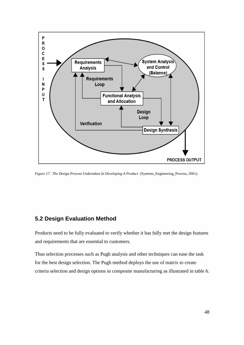
Figure 17, below, shows the relevant stages to undertake when developing and
manufacturing a product.
48
Figure 17. The Design Process Undertaken In Developing A Product (Systems_Engineering_Process, 2001).
5.2 Design Evaluation Method
Products need to be fully evaluated to verify whether it has fully met the design features
and requirements that are essential to customers.
Thus selection processes such as Pugh analysis and other techniques can ease the task
for the best design selection. The Pugh method deploys the use of matrix to create
criteria selection and design options in composite manufacturing as illustrated in table 6.
49
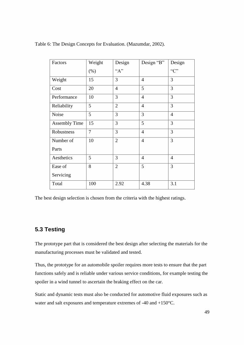
Table 6: The Design Concepts for Evaluation. (Mazumdar, 2002).
Factors Weight
(%)
Design
“A”
Design “B” Design
“C”
Weight 15 3 4 3
Cost 20 4 5 3
Performance 10 3 4 3
Reliability 5 2 4 3
Noise 5 3 3 4
Assembly Time 15 3 5 3
Robustness 7 3 4 3
Number of
Parts
10 2 4 3
Aesthetics 5 3 4 4
Ease of
Servicing
8 2 5 3
Total 100 2.92 4.38 3.1
The best design selection is chosen from the criteria with the highest ratings.
5.3 Testing
The prototype part that is considered the best design after selecting the materials for the
manufacturing processes must be validated and tested.
Thus, the prototype for an automobile spoiler requires more tests to ensure that the part
functions safely and is reliable under various service conditions, for example testing the
spoiler in a wind tunnel to ascertain the braking effect on the car.
Static and dynamic tests must also be conducted for automotive fluid exposures such as
water and salt exposures and temperature extremes of -40 and +150°C.

50
Thermal cycling testing is also carried out and the effect of the test done on the spoiler
at two extreme temperatures and stone impingement helps to understand the
performance and stability of the spoiler product.
6. RESULTS
6.1 COMPOSITE REAR SPOILER
The materials used to fabricate the rear spoiler are glass fibre and polyester resin.
Composite properties are mostly determined by their chemical and mechanical
interaction with other combined materials.
“The reinforcing material or fiber provides strength and stiffness to the composite
whereas the matrix adds rigidity and environmental resistance”. (Mazumdar, 2002).
Figure 18. Composite formation. (Mazumdar, 2002).
6.2 Fiberglass
Fiberglass materials are made by the combination of two or more materials to obtain a
unique combination of material properties. In this experiment the fibre reinforced
composite material used primarily as it main structural component is E-glass fiber.
The E-Glass is made of a continuous strand of filaments that are plied and twisted into
yarns. It is relatively lightweight with moderate tensile and compressive strength as well
51
as high strength and dimensional stability. The light weight nature of fiberglass makes it
ideal and durable in applications such as manufacturing rear spoilers.
It has excellent electrical properties and design flexibility which gives it optimum
performance. This makes it excellent material to use in situations where strength and
high electrical resistivity is required.
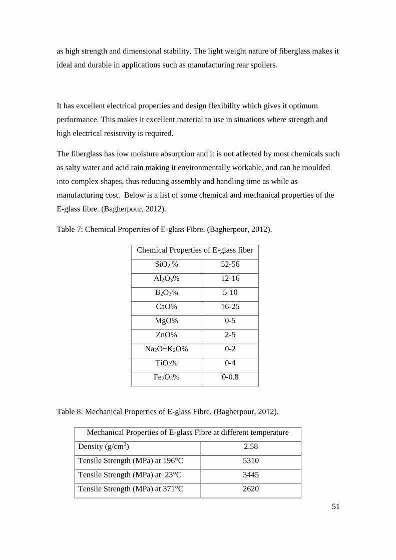
The fiberglass has low moisture absorption and it is not affected by most chemicals such
as salty water and acid rain making it environmentally workable, and can be moulded
into complex shapes, thus reducing assembly and handling time as while as
manufacturing cost. Below is a list of some chemical and mechanical properties of the
E-glass fibre. (Bagherpour, 2012).
Table 7: Chemical Properties of E-glass Fibre. (Bagherpour, 2012).
Chemical Properties of E-glass fiber
SiO2 % 52-56
Al2O3% 12-16
B2O3% 5-10
CaO% 16-25
MgO% 0-5
ZnO% 2-5
Na2O+K2O% 0-2
TiO2% 0-4
Fe2O3% 0-0.8
Table 8: Mechanical Properties of E-glass Fibre. (Bagherpour, 2012).
Mechanical Properties of E-glass Fibre at different temperature
Density (g/cm3) 2.58
Tensile Strength (MPa) at 196°C 5310
Tensile Strength (MPa) at 23°C 3445
Tensile Strength (MPa) at 371°C 2620
52
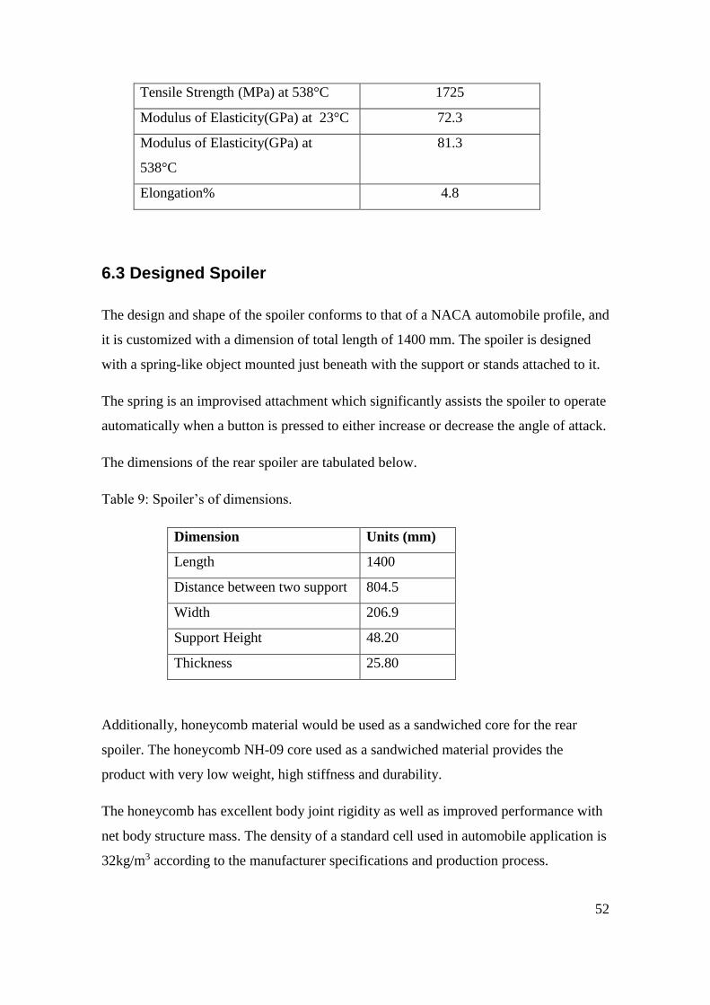
Tensile Strength (MPa) at 538°C 1725
Modulus of Elasticity(GPa) at 23°C 72.3
Modulus of Elasticity(GPa) at
538°C
81.3
Elongation% 4.8
6.3 Designed Spoiler
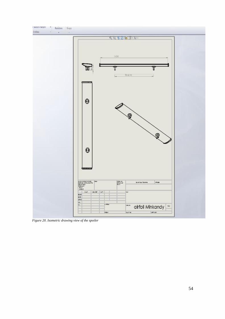
The design and shape of the spoiler conforms to that of a NACA automobile profile, and
it is customized with a dimension of total length of 1400 mm. The spoiler is designed
with a spring-like object mounted just beneath with the support or stands attached to it.
The spring is an improvised attachment which significantly assists the spoiler to operate
automatically when a button is pressed to either increase or decrease the angle of attack.
The dimensions of the rear spoiler are tabulated below.
Table 9: Spoiler’s of dimensions.
Dimension Units (mm)
Length 1400
Distance between two support 804.5
Width 206.9
Support Height 48.20
Thickness 25.80
Additionally, honeycomb material would be used as a sandwiched core for the rear
spoiler. The honeycomb NH-09 core used as a sandwiched material provides the
product with very low weight, high stiffness and durability.
The honeycomb has excellent body joint rigidity as well as improved performance with
net body structure mass. The density of a standard cell used in automobile application is
32kg/m3 according to the manufacturer specifications and production process.

53
Figure 19. Solidworks Design of spoiler
54
Figure 20. Isometric drawing view of the spoiler

55
6.4 The Manufacturing Process
The spoiler is manufactured using a vacuum infusion process, whereby the vacuum
pressure is used to drive resin into the laminate. Thus the vacuum reduces the pressure
at one end of the fabric stack allowing atmospheric pressure to force the resin through
the layers of glass fibers. The speed and the distance to infuse the stack of fiberglass
will be dependent on the relationship between the resin viscosity systems with respect to
the speed of the infusion process as given below: (Gurit, 2014)
𝜐 ≈ 𝐷𝛥𝑃
𝜂 [Eq. 9]
The viscosity of the resin system η
The permeability of the fabric stack D
The pressure gradient acting on the infused resin 𝛥𝑃
Thus the speed of the infusion process (υ) increases with increasing permeability of the
stack of fibre (D) with increasing pressure gradient (𝛥𝑃) while it decreases with
increasing viscosity (η). The mould consists of two halves, which are the female and
the male part. The process has a better fibre to resin ratio and produces a strong
laminate with a low void content than other processes such as hand laminate.
The required equipment used in this process is Chemlease 75 which helps to eliminate
debris in the prepared mould. Peel ply and release film are placed inside the mould,
whereas a flow mat over the release film to provides an easy flow passage or conduit for
the resin. Vacuum and resin lines are carefully set up to avoid air leakage before the
vacuum is switched on for the infusion process. Afterwards the two halves will be
carefully assembled.
56
6.4.1 Laminate Preparation
A female mould with a curvature profile of that of the spoiler face would be prepared
and the lamination would be structured to have a symmetrical fiber orientation.
The fiber orientation of [0+45/90] which would be a 4 layer fabrication is considered
for the design. The prepared half profile of the spoiler will be fitted into the female
mould which is of the same copy as that of the half spoiler profile.
In “The Fundamental Principles of Composite Materials Stiffness Predictions” the
Krenchel factor takes into account the angle of the fibre in the rule of mixtures.
(Richardson, n.d)
Therefore, Ec = ηɵEfVf + EmVm [Eq.10]
Reinforcing Efficiency; ηɵ=∑ 𝑎 n Cos4ɵ [Eq.11]
Where; Ec Young Modulus of the composite
Ef Young Modulus of the fiberglass
Vf Volume fraction of the fiberglass
Em Young Modulus of the matrix
Vm Volume fraction of the matrix
Hence, the efficiency factor for the laminate lay up [0+45/90]
Where: ηɵ= Cos4ɵ [Eq.12]
0°= 1
45°= 0.7071
90°= 0

57
Laminate in the x-direction.
(0.65*1) + (0.35*0.25) =0.7375
Laminate in the y-direction.
(0.65*0) + (0.35*0.25) = 0.0875
Prediction of the Young Modulus in x-y direction
Ex = ηɵEfVf + EmVm
Ef = 25GPa, Em = 3.5GPa, Vf = 0.65, Vm= 0.35
Ex= (0.07375*25*109*0.65) + (3.5*109*0.35)
= 13.21GPa
Ey = ηɵEfVf + EmVm
Ey = (0.0875*25*109*0.65) + (3.5*109*0.35)
= 2.65GPa
6.4.2 Resin Preparation
The resin used in this lamination is polyester resin which is extensively discussed in
chapter two. A locally manufactured polyester resin with a code R 10-03 would be used
because of its rigid orthopthalic nature. A mixed styrene monomer will be added to the
resin to decrease the viscosity of the resin. Hardener with a ratio of 100:33 would be
mixed with the resin to start the curing process and also build a thorough crosslinking in
order to make the laminate stiffer.
58
6.4.3 Lamination Process
The pre oriented half profile would be covered with peel ply film to help detach the
laminate from the assembly whereas on top of it a release film is applied which serves
as a conduit for easy flow of resin. The laminate would then be wrapped up with a flow
mat that will evenly help in distributing the resin thoroughly over the lamination.
The laminate is effectively done with inlet and outlet pipes for resin injection as well as
for exhaling air traps after the laminate is covered with vacuum bag and finally sealed
with adhesive tapes.
This would be followed up with fixing the male mould against the female mould to
close and complete its formation. The resin is gently released into the mould for
uniform distribution over the frame profile, and then the vacuum is opened for the
infusion process to commence. Finally sanding and trimming of unwanted parts should
to be done after the lamination process.
6.5 Downforce of the Rear Spoiler
In the “Theory of Wing Sections” the lift force of a wing is expressed as:
fL = 1
2ρ υ2S cL [Eq.13] [Abbot and Doenhoff, 1959]
But, since downforce is anti-lift, then the downforce of the spoiler can be written as;
Df = 1
2ρ υ2A cL [Eq.14]
Where: Df Downforce
Ρ Density of moving air particle
υ Velocity of the flowing wind
cL Co-efficient of lift
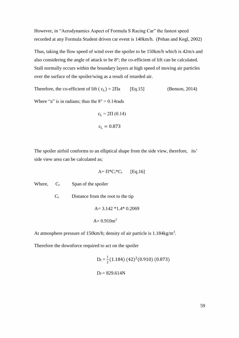
59
However, in “Aerodynamics Aspect of Formula S Racing Car” the fastest speed
recorded at any Formula Student driven car event is 140km/h. (Pehan and Kegl, 2002)
Thus, taking the flow speed of wind over the spoiler to be 150km/h which is 42m/s and
also considering the angle of attack to be 8°; the co-efficient of lift can be calculated.
Stall normally occurs within the boundary layers at high speed of moving air particles
over the surface of the spoiler/wing as a result of retarded air.
Therefore, the co-efficient of lift ( cL) = 2Πa [Eq.15] (Benson, 2014)
Where “a” is in radians; thus the 8° = 0.14rads
cL = 2Π (0.14)
cL = 0.873
The spoiler airfoil conforms to an elliptical shape from the side view, therefore, its’
side view area can be calculated as;
A= Π*Cr*Ct [Eq.16]
Where, Cr Span of the spoiler
Ct Distance from the root to the tip
A= 3.142 *1.4* 0.2069
A= 0.910m2
At atmosphere pressure of 150km/h; density of air particle is 1.184kg/m3.
Therefore the downforce required to act on the spoiler
Df = 1
2(1.184) (42)2(0.910) (0.873)
Df = 829.614N

60
Figure 21: Co-efficient of lift versus Angle of Attack at high Reynolds number (Abbot and Doenhoff, 1959)

61
In order to determine the type of flow within the set speed limit the Reynolds number is
calculated.
𝑅𝑒 =𝜌 𝑉𝐿
µ
Considering, air particles at 1 atmospheric pressure at 25°C, the kinematic viscosity is
1.5*10-5 m2/s. (Yunus, 2008, p.798)
However, the chord width of the spoiler = 206.9mm = 0.2069m
𝑅𝑒 =((1.184) (42) (0.2069)) / (1.5*10-5)
𝑅𝑒 = 6.7*105
Therefore, based on the results of the Reynolds number the flow is turbulent.
Thus, the maximum stress on the spoiler when a uniform load of 829.614N of down
force acts on it can be calculated using the geometry below. (Engineers edge, 2014).
Figure 22: Beam Deflection with uniform load/downforce

62
δmax= 𝐹
2𝐼𝑙 [c]2 [Eq.17]
But 𝐼 = 𝜋𝑠𝑡3
4 [Eq.18]
Where: δ Stress at the cross-section being evaluated
F Downforce acting on the spoiler
x Distance as indicated
u Some distance as indicated
l Distance between the two support
I Distance from the neutral axis to the extreme fiber edge
S Width of the airfoil
t Thickness of the of the airfoil
The closest shape of the airfoil when viewed from the side is taken to be an elliptical
solid cross section. The toughness and stiffness of any cross section is subjected to
stress and mass moment of inertia about the centroid. Therefore, the mass moment of
inertia about the centroid of the solid cross section taking from the side view is given as:
Figure 23. Side view of an airfoil (Abbot and Doenhoff, 1959)
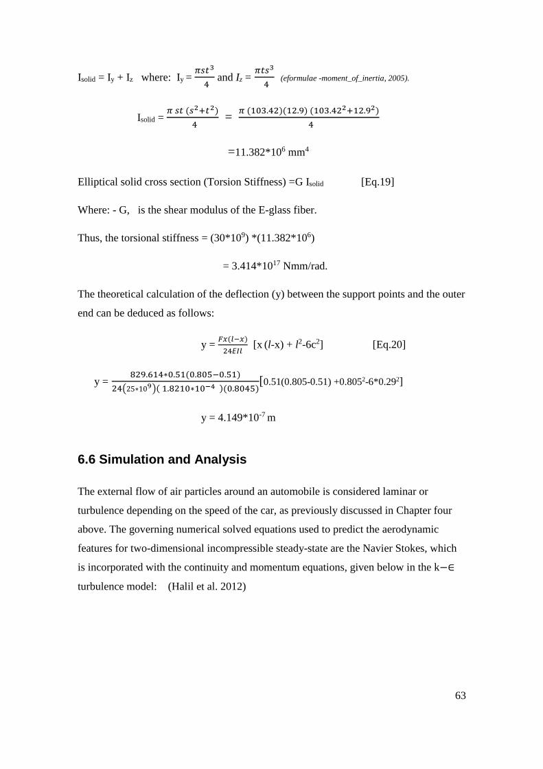
63
Isolid = Iy + Iz where: Iy = 𝜋𝑠𝑡3
4 and Iz =
𝜋𝑡𝑠3
4 (eformulae -moment_of_inertia, 2005).
Isolid = 𝜋 𝑠𝑡 (𝑠2+𝑡2)
4 =
𝜋 (103.42)(12.9) (103.422+12.92)
4
=11.382*106 mm4
Elliptical solid cross section (Torsion Stiffness) =G Isolid [Eq.19]
Where: - G, is the shear modulus of the E-glass fiber.
Thus, the torsional stiffness = (30*109) *(11.382*106)
= 3.414*1017 Nmm/rad.
The theoretical calculation of the deflection (y) between the support points and the outer
end can be deduced as follows:
y = 𝐹𝑥(𝑙−𝑥)
24𝘌𝐼𝑙 [x (l-x) + l2-6c2] [Eq.20]
y = 829.614∗0.51(0.805−0.51)
24(25∗109)( 1.8210∗10−4 )(0.8045)[0.51(0.805-0.51) +0.8052-6*0.292]
y = 4.149*10-7 m
6.6 Simulation and Analysis
The external flow of air particles around an automobile is considered laminar or
turbulence depending on the speed of the car, as previously discussed in Chapter four
above. The governing numerical solved equations used to predict the aerodynamic
features for two-dimensional incompressible steady-state are the Navier Stokes, which
is incorporated with the continuity and momentum equations, given below in the k−∈
turbulence model: (Halil et al. 2012)

64
𝜕𝜇
𝜕𝑥+
𝜕𝜐
𝜕𝑦 = 0 [Eq.20]
𝜌 ( 𝜇 𝜕𝜇
𝜕𝑥+ 𝜐
𝜕𝜐
𝜕𝑦 ) = -
𝜕𝜌
𝜕𝑥 + 𝜇 (
𝜕2µ
𝜕𝑥2+
𝜕2µ
𝜕𝑦2) [Eq. 21]
𝜌 ( 𝜇 𝜕𝜇
𝜕𝑥+ 𝜐
𝜕𝜐
𝜕𝑦 ) = -
𝜕𝜌
𝜕𝑥 + 𝜇 (
𝜕2𝜐
𝜕𝑥2+
𝜕2𝜐
𝜕𝑦2) [Eq.22]
The k−∈ turbulence model illustrates two terms with the k symbolizing the turbulent
kinetic energy of the transported variables whereas the second transported term -∈ is the
turbulent dissipation which determines the rate of dissipation of the turbulent kinetic
energy.
6.7 Finite Element Analysis (FEA)-Nastran
A static load simulation is applied to the spoiler which conforms to a NACA four digit
deep cambered thin section airfoil with Nastran software.
The Nastran software is written in FORTRAN which is an imperative programming
language that is applicable in evaluating scientific and numerical computational models.
Mathematically, the finite element analysis (FEA) provides numerical approximate
solutions to partial differential equations to minimize an error function and give stable
solution. The spoiler was analyzed with a uniform load of 829.614 N, which is the
maximum downforce of the designed spoiler. This resulted to a maximum stress of
2.309 MPa at a displacement of 4.451 mm. Further analysis was executed with uniform
load between 700 N to 100 N with their corresponding stress and displacement as
tabulated below.
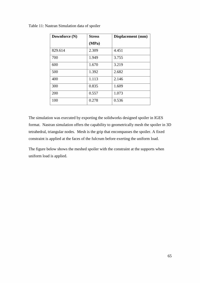
65
Table 11: Nastran Simulation data of spoiler
Downforce (N) Stress
(MPa)
Displacement (mm)
829.614 2.309 4.451
700 1.949 3.755
600 1.670 3.219
500 1.392 2.682
400 1.113 2.146
300 0.835 1.609
200 0.557 1.073
100 0.278 0.536
The simulation was executed by exporting the solidworks designed spoiler in IGES
format. Nastran simulation offers the capability to geometrically mesh the spoiler in 3D
tetrahedral, triangular nodes. Mesh is the grip that encompasses the spoiler. A fixed
constraint is applied at the faces of the fulcrum before exerting the uniform load.
The figure below shows the meshed spoiler with the constraint at the supports when
uniform load is applied.
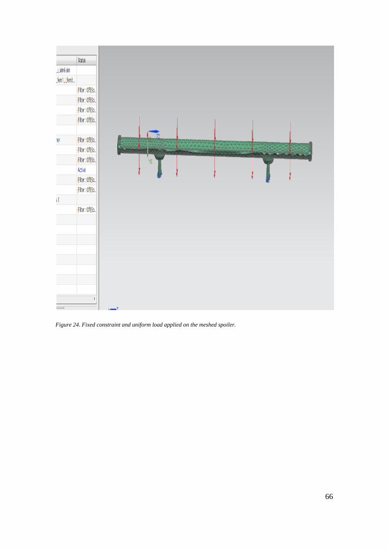
66
Figure 24. Fixed constraint and uniform load applied on the meshed spoiler.

67
Figure 25. Maximum Stress of the spoiler at maximum downforce.
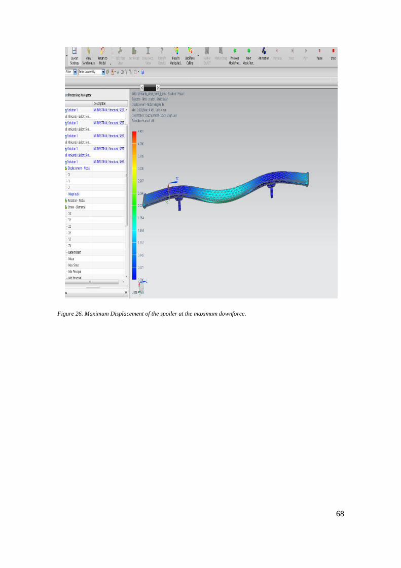
68
Figure 26. Maximum Displacement of the spoiler at the maximum downforce.
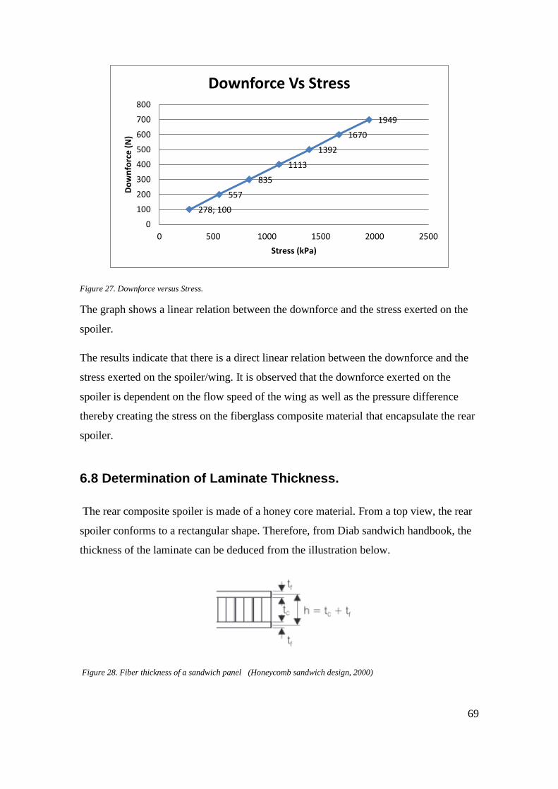
69
Figure 27. Downforce versus Stress.
The graph shows a linear relation between the downforce and the stress exerted on the
spoiler.
The results indicate that there is a direct linear relation between the downforce and the
stress exerted on the spoiler/wing. It is observed that the downforce exerted on the
spoiler is dependent on the flow speed of the wing as well as the pressure difference
thereby creating the stress on the fiberglass composite material that encapsulate the rear
spoiler.
6.8 Determination of Laminate Thickness.
The rear composite spoiler is made of a honey core material. From a top view, the rear
spoiler conforms to a rectangular shape. Therefore, from Diab sandwich handbook, the
thickness of the laminate can be deduced from the illustration below.
Figure 28. Fiber thickness of a sandwich panel (Honeycomb sandwich design, 2000)
1949
1670
1392
1113
835
557
278; 100
0
100
200
300
400
500
600
700
800
0 500 1000 1500 2000 2500
Do
wn
forc
e (
N)
Stress (kPa)
Downforce Vs Stress
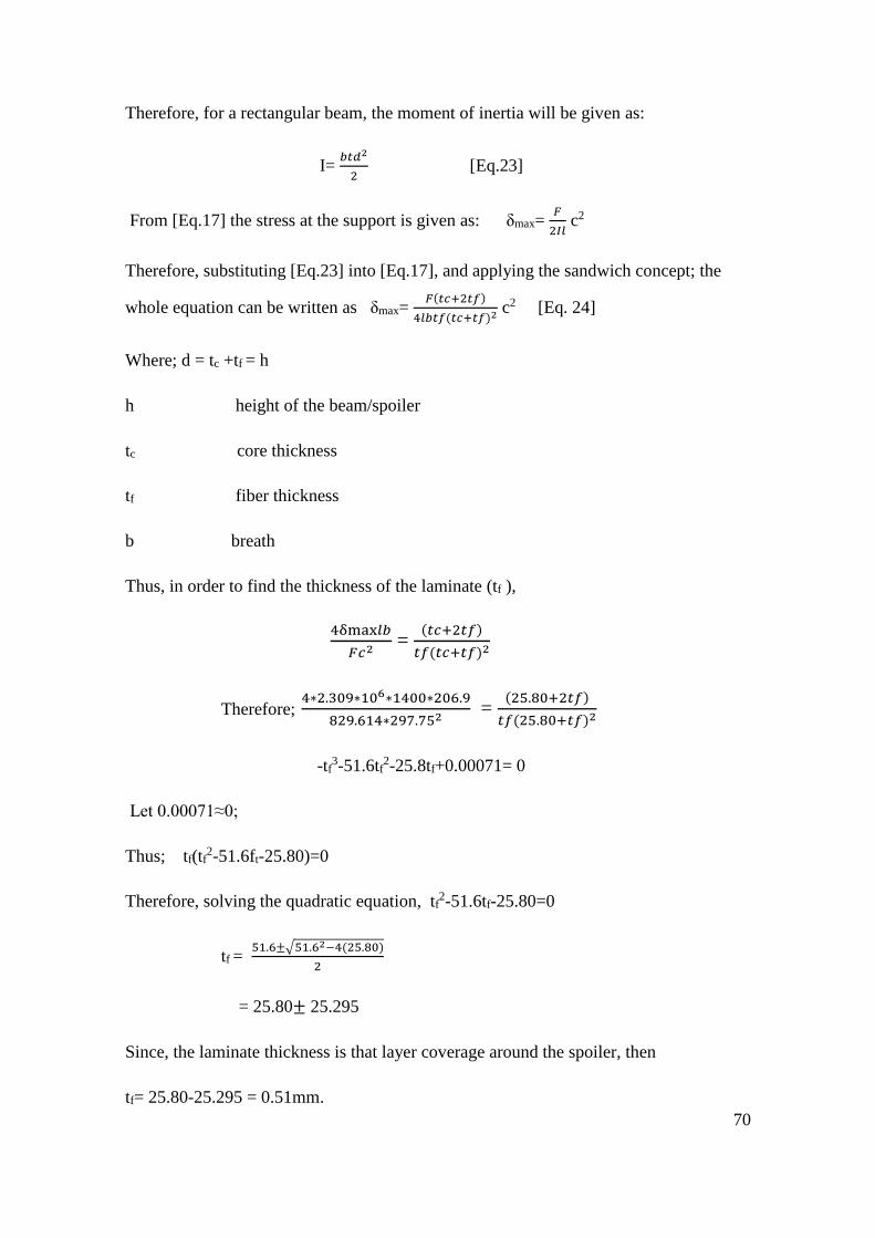
70
Therefore, for a rectangular beam, the moment of inertia will be given as:
I= 𝑏𝑡𝑑2
2 [Eq.23]
From [Eq.17] the stress at the support is given as: δmax= 𝐹
2𝐼𝑙 c2
Therefore, substituting [Eq.23] into [Eq.17], and applying the sandwich concept; the
whole equation can be written as δmax= 𝐹(𝑡𝑐+2𝑡𝑓)
4𝑙𝑏𝑡𝑓(𝑡𝑐+𝑡𝑓)2 c2 [Eq. 24]
Where; d = tc +tf = h
h height of the beam/spoiler
tc core thickness
tf fiber thickness
b breath
Thus, in order to find the thickness of the laminate (tf ),
4δmax𝑙𝑏
𝐹𝑐2 =
(𝑡𝑐+2𝑡𝑓)
𝑡𝑓(𝑡𝑐+𝑡𝑓)2
Therefore; 4∗2.309∗106∗1400∗206.9
829.614∗297.752 =
(25.80+2𝑡𝑓)
𝑡𝑓(25.80+𝑡𝑓)2
-tf3-51.6tf
2-25.8tf+0.00071= 0
Let 0.00071≈0;
Thus; tf(tf2-51.6ft-25.80)=0
Therefore, solving the quadratic equation, tf2-51.6tf-25.80=0
tf = 51.6±√51.62−4(25.80)
2
= 25.80± 25.295
Since, the laminate thickness is that layer coverage around the spoiler, then
tf= 25.80-25.295 = 0.51mm.
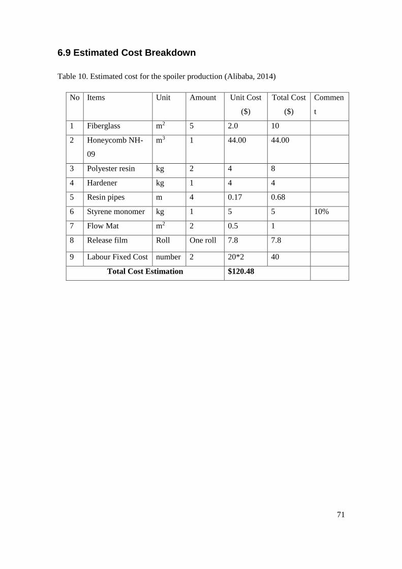
71
6.9 Estimated Cost Breakdown
Table 10. Estimated cost for the spoiler production (Alibaba, 2014)
No Items Unit Amount Unit Cost
($)
Total Cost
($)
Commen
t
1 Fiberglass m2 5 2.0 10
2 Honeycomb NH-
09
m3 1 44.00 44.00
3 Polyester resin kg 2 4 8
4 Hardener kg 1 4 4
5 Resin pipes m 4 0.17 0.68
6 Styrene monomer kg 1 5 5 10%
7 Flow Mat m2 2 0.5 1
8 Release film Roll One roll 7.8 7.8
9 Labour Fixed Cost number 2 20*2 40
Total Cost Estimation $120.48
72
7. DISCUSSION
This thesis primarily focused on the product design method necessary to manufacture a
composite rear spoiler. It touches on the composite material and its properties as well as
the suitable method in selecting an airfoil to produce the rear spoiler. The most cost
effective method was considered in the manufacturing process for the rear spoiler.
However, the study was based on a lot of research work deployed in the theory of wing
profile and its essential functionalities. It also focused on NACA profile of a four digit
wing and some applied knowledge acquired from NASA articles.
The spoiler is dimensioned with a chordline of 1400mm and the downforce of 829.614N
which was theoretically calculated with assumption of an angle of attack of 8 degrees
and wind velocity of 150km/h.
Moreover, the Nastran simulation focused on the most important feature, that is, with
the calculated downforce, the maximum stress and displacement exerted on the
fiberglass composite rear spoiler.
The effect of the composite sandwich in this design with the thin thickness serves as an
effective method to increase bending rigidity without compromising with the structural
weight.
73
8. CONCLUSION
This thesis work deployed the use of product design methods in the manufacturing of
fiberglass rear car spoiler and Solidworks software for the design of the rear spoiler.
The Nastran NX 8 software was used to simulate and analyze the effect of uniform load
when exerted on the fiberglass rear spoiler and the stress it will create on it.
This study was accomplished with some assumptions around the geometry of the rear
spoiler with an angle of attack of 8 degrees and the wind speed of 150 km/h in order to
calculate the maximum downforce of 829.614 N for the spoiler.
The maximum downforce of 829.614 N was used to analyze the maximum stress on the
rear spoiler and this resulted to 2.309 MPa.
However, further simulation was done with downforce from 100 N to 700 N. This
shows that the downforce exerted on the spoiler is dependent on the flow speed of the
wing as well as the pressure difference thereby creating the stress on the fiberglass
composite material that encompasses the rear spoiler.
The lightweight sandwiched structure with a thickness of 0.51 mm provides the overall
stiffness to the spoiler. The thin thickness withstood the stress of 2.309 MPa meted on it
by the downforce. The stress theoretically calculated for the elliptical shaped airfoil
from the side view is an evident that some of the finite elements cannot be totally
accounted for, as the simulation outcome accomplished.

74
9. SUGGUESTION FOR FURTHER WORK
This piece of work can be pursued by designing and building a prototype of the
composite rear spoiler at the laboratory.
However, further analysis and simulation can be considered; that is different angle of
attack for the rear spoiler can be graphed at different downforce.
Wind tunnel testing can be considered when a prototyped rear spoiler is designed and
manufactured.

75
10. REFERENCE
Abbot, H. I. & Doenhoff, A. E. V., 1959. Theory of Wing Section. New York: Dover
Publications, Inc.
National Aeronautics and Space Administration.n.d. Airfoil [ImageOnline] Available at:
<http://www.engineering108.com/Data/Engineering/aeronautical_engineering/Basics-
of-Aeronautics.pdf>[Accessed June 2014].
Alibaba, 2014. Alibaba Group. [Online] Available at:
<http://www.alibaba.com/showroom/fiberglass-price.html>[Accessed 20 November
2014].
Alibaba, 2014. Alibaba Group. [Online] Available at:
<http://www.alibaba.com/showroom/polyester-resin-price>[Accessed 20 November
2014].
Alibaba, 2014. Alibaba Group. [Online] Available at :
<http://www.alibaba.com/showroom/pu-hardener.html>[Accessed 21 November 2014].
Alibaba, 2014. Alibaba Group. [Online] Available at:
<http://www.alibaba.com/showroom/resin-pipe.html>[Accessed 21 November 2014].
Alibaba, 2014. Alibaba Group. [Online] Available at:
<http://www.alibaba.com/showroom/styrene.html>[Accessed 21 November 201
Car Spoiler. [Online] Available at: <http://www.171car.com/lip-spoiler>[Accessed 28
May 2014].
Composite Overview. [Online] Available at:
<http://web.mit.edu/course/3/3.064/www/slides/composites_overview.pdf>
[Accessed 18 June 2014].
UScomposites. [Online] Available at: <http://www.uscomposites.com/specialty.html>
[Accessed 4 November 2014].
Bader, S., 2005. Crystic Composites Handbook. 16th ed. Northamptonshire: Scott Bader
Company Ltd.
76
Bagherpour, S., 2012. Material Science Polymer. Fiber Reinforced Polyester Composites,
26 September, p. Chapter 6.
Beigmoradi, S., Jahani, K., Keshavarz, A. & Bayani, K. M., 2013. Aerodynamic Noise
Source Identificationn for a Coupe Passenger Car by Numerical Method Focusing on the
Effect of the Rear Spoiler. SAE International, 8 April.
Benson, T., 2014. National Aeronautic and Space Administration. [Online] Available
at: <http://www.grc.nasa.gov/WWW/k-12/airplane/geom.html>[Accessed 20 October
2014].
Benson, T., 2014. National Aeronautic and Space Administration. [Online] Available
at: <http://www.grc.nasa.gov/WWW/k-12/airplane/incline.html>[Accessed 21 October
2014].
Benson, T., 2014. National Aeronautical & Space Administration. [Online]
Available at: <http:// www.grc.nasa.gov/WWW/k-12/airplane/area> [Accessed 21
October]
Benson, T., 2014. National Aeronautics and Space Administration. [Online]
Available at: <http://www.grc.nasa.gov/WWW/BGH/machrole.html>
[Accessed 14 October 2014].
Benson, T., 2014. Newton's First Law. [Online] Available at:
<http://www.grc.nasa.gov/WWW/k-12/airplane/newton1g.html>[Accessed 27 October
2014].
Casiraghi, C., 2010. Race Car Aerodynamics, Stockholm: s.n.
Chang, K., 1998. Web Cadet Corps. [Online] Available at:
<http://www.webcadets.com/training/afctp/pilot_2.php/lesson_6>[Accessed 5 June
2014].
Hexcel Composite. December 2000. Honeycomb Sandwich Design Technology. Issue
AGU 075b.

77
Fiber Glast Development Corporation. n.d. Composite. [Online] Available at:
<http://www.composites.ugent.be/home_made_composites/documentation/Fiberglast_
vacuuminfusion.pdf>[Accessed 20 June 2014].
Corrado, P., 2001. Design for Manufacturing: A Structrural Approach. s.l.:Elsevier
Science & Technology .
Cripps, D., 2014. Netcomposites. [Online] Available at:
<http://www.netcomposites.com/guide/epoxy-resins/10>[Accessed 1 October 2014].
Department of Defense, 2001. System Engineering Fundamentals, Virginia: Defense
Acquisition University Press. [Image Online] available at:
<http://ocw.mit.edu/courses/aeronautics-and-astronautics/16-885j-aircraft-systems-
engineering-fall 2005/readings/sefguide_01_01.pdf.Ch.1,p.6.
Diab, 2001. Divinycell Sandwich Concept. [Online] Available at:
<http://www.carmas.com.ar/DOWN/DIVINYCELL/HBook.pdf>[Accessed 23
November 2014].
eformulae, 2005. Eformulae_moment_of_inertia. [Online] Available at:
<http://www.eformulae.com/engineering/moment_of_inertia.php>[Accessed 10
November 2014].
Racecar engineering, 2006. F1: Adjustable rear wings how they work. [Online]
Available at:<http://www.racecar-engineering.com/articles/f1/f1-adjustable-rear-wings-
how-they-work/>[Accessed 25 May 2014].
Engineer's, Handbook, 2006. Composite Molding Processes. [Online] Available at:
<http://engineershandbook.com/>[Accessed June 2014].
Gartner, M., 1999. Race Car Design-Aerodynamics. [Online] Available at:
<http://www.gmecca.com/byorc/dtipsaerodynamics>[Accessed 4 June 2014].
Generalic, E., 2014. Laminar flow. [Online] Available at:
<http://glossary.periodic.com[Accessed 18 July 2014].
Glenn, E., 2014. The Physics Hypertextbook. [Online] Available at:
<http://physics.info/drag/>[Accessed 27 June 2014].
78
Groote, S. D., 2009. F1 Technical. [Online] Available at:
<http://www.f1technical.net/articles/10>[Accessed 6 July 2014].
Gurit, 2014. Wind Energy Handbook. [Online] Available at:
<http://www.gurit.com/files/documents/4_bladeprocesses.pdf>[Accessed 22 November
2014].
Hall, J. E., Mrlik, J. R. & Winchell, F. J., 1969. Aerodynamic Spoiler for Automotive
vehicles. USA, Patent No. US3455594 A.
Haney, P., 2000. Inside racing Technology. [Online] Available at:
<http://www.insideracingtechnology.com/tech103anglattack.htm>[Accessed 15 October
2014].
Honeycomb, N., 2010. Nomex Honeycomb core. [Online] Available at:
<http://www.acp-composites.com/honeycomb.pdf>[Accessed 7 December 2014].
Karman, T. V., 1954. Aerodynamics; Selected Topics In The Light Of Their Historical
Development. London: McGraw-Hill Books Company, Inc.
Kasravi, n.d. Vehicle Aerodynamics. [Online] Available at:
<http://www.kasravi.com/cmu/tec452/aerodynamics/VehicleAero.htm >[Accessed 20
August 2014].
Katz, J., 1996. Race Car Aerodynamics. 1 ed. Massachusetts: Bentley.
Katz, J., 2006. Aerodynamics of Race Cars. [Online] Available at:
<http://www.strangeholiday.com/oops/stuff/annurev.fluid.38.050304.092016.pdf >
[Accessed 10 July 2014].
United States Department of Labour, 1999. Occupational Safety & Health
Administration. [Online] Available at:
<https://www.osha.gov/dts/osta/otm/otm_iii/otm_iii_1.html >[Accessed 28 June 2014].
Lubin, G., 1982. Handbook of Composites. New York: Van Nostrand Reinhold.
Mazumdar, S. K., 2002. Composites Manufacturing; Materials, Products and Process
Engineering. New York: CRC Press.
79
McLennan, A. J., Zeimentz, P. M. & Laborda, S., 2010. Vinyl acetate/nealkanoic acid
vinyl ester copolymer and uses thereof. USA, Patent No. US20100167609A1.
Muzzupappa, M. & Pagnotta, L., 2002. Optimum Design of A Formula One Rear Wing
Using A Genetic Algorithm. International Design Conference -Design, 14 May, pp.1-6.
Nachiketa, T., n.d. Introduction to Composite Materials and Structures. [Online]
Available at: <http://nptel.ac.in/courses/112104168/L08>[Accessed 4 June 2014].
Pandey, P. P., 2004. Composite Materials. [Online] Available at:
<http://nptel.iitk.ac.in/courses/Webcoursecontents/IIScBANG/Composite%20Materials/
Learning%20material%20-%20composite%20material.pdf >[Accessed 19 July 2014].
Parry, D. L., 2014. Langley Flying School. [Online] Available at:
<http://www.langleyflyingschool.com/Pages/CPGS%204%20Aerodynamics%20and%2
0Theory%20of%20Flight%20Part%201.html [Accessed 22 November 2014].
Rapid-racer, n.d. [Online] Available at: <http://www.rapid-racer.com/aerodynamics>
[Accessed 3 July 2014].
Richardson, D., n.d. The Fundamental Principles of Composite Material Stiffness
Prediction. [Online] Available at: <http://www.swcompositesgateway.co.uk/property-
prediction.pdf>[Accessed 15 November 2014].
Roylance, D., 2000. Introduction to Composite Materials. [Online] Available at:
<http://ocw.mit.edu/courses/materials-science-and engineering/3-11-mechanics-of-
materials-fall-1999/modules/composites.pdf>[Accessed 25 August 2014].
Sadraey, M., 2013. Wing Design. [Online] Available at:
<http://faculty.dwc.edu/sadraey/chapter 5. Wing Design.pdf>[Accessed 10 June 2014].
Schwartz, n.d. The Structure of Polyester. [Online] Available at:
<http://schwartz.eng.auburn.edu/polyester/structure.html>[Accessed 10 October 2014].
Singh, R. & Ganesh, S., n.d. Composite Manufacturing. [Online] Available at:
<http://www.me.iitb.ac.in/~ramesh/ME338/comp.pdf>[Accessed 12 June 2014].
80
Sunanda, M. & Nayak, S., 2013. Analysis of NACA 2412 for Automobile Rear Spoiler
Using Composite Material. Internal Journal of Emerging Technology and Advanced
Engineering, January, 3(1), pp. 236-242.
Suong, H. V., 2009. Principles of the Manufacturing of Composite. [Online]
Available at: <http://www.tnu.edu.vn/khoann/lectures/Introduction Composite
material/Compsoite Manufacturing techniques.pdf>[Accessed 12 June 2014].
Ting, K. W., 2010. Automatic Adjustable Vehicle Spoiler System. s.l. Patent No.
WO2010030158 A1.
Yunus, A. C., 2008. Introduction to Thermodynamics & Heat Transfer . In: 2nd, ed.
Nevada: The McGraw Hill Companies, p. 798.
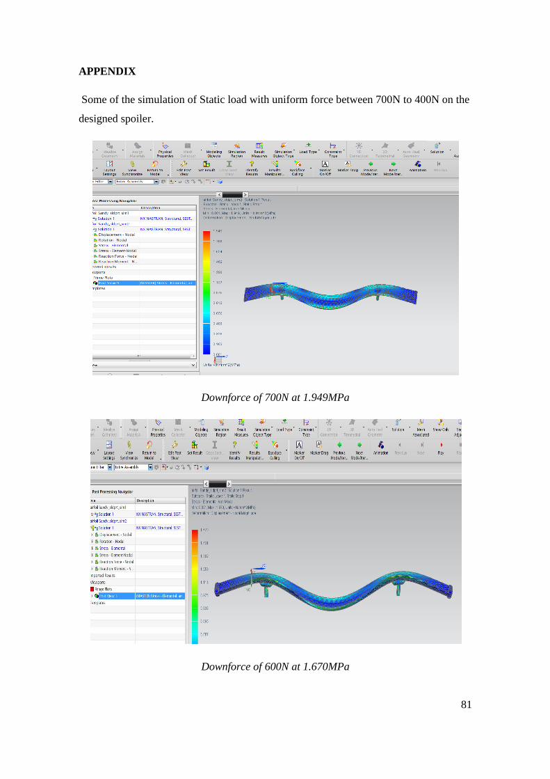
81
APPENDIX
Some of the simulation of Static load with uniform force between 700N to 400N on the
designed spoiler.
Downforce of 700N at 1.949MPa
Downforce of 600N at 1.670MPa
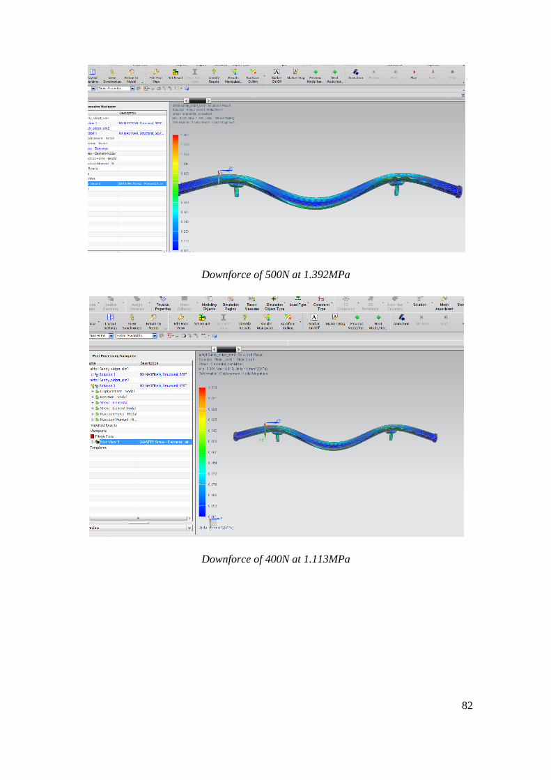
82
Downforce of 500N at 1.392MPa
Downforce of 400N at 1.113MPa