Composite beams - author.uthm.edu.myauthor.uthm.edu.my/uthm/www/content/lessons/2969... · Guidance...
28
Chapter 21 Composite beams by MARK LAWSON and PETER WICKENS 601 21.1 Applications of composite beams In buildings and bridges, steel beams often support concrete slabs. Under load each component acts independently with relative movement or slip occurring at the inter- face. If the components are connected so that slip is eliminated, or considerably reduced, then the slab and steel beam act together as a composite unit (Fig. 21.1). There is a consequent increase in the strength and stiffness of the composite beam relative to the sum of the components. The slab may be solid in situ concrete or the composite deck slab considered in Chapter 20. It may also comprise precast concrete units with an in situ concrete topping. In buildings, steel beams are usually of standard UB scction, but UC and asymmetric beam sections are sometimes used where there is need to minimize the beam depth. A typical building under construction is shown in Fig. 21.2. Welded fab- ricated sections are often used for long-span beams in buildings and bridges. Design of composite beams in buildings is now covered by BS 5950: Part 3, 1 although guidance was formerly available in an SCI publication. 2 The design of com- posite beams incorporating composite slabs is affected by the shape and orientation of the decking, as indicated in Fig. 21.3. One of the advantages of composite construction is smaller construction depths. Services can usually be passed beneath, but there are circumstances where the beam depth is such that services can be passed through the structure, either by forming large openings, or by special design of the structural system. A good example of this is the stub-girder. 3 The bottom chord is a steel section and the upper chord is the concrete slab. Short steel sections or ‘stubs’ are introduced to transfer the forces between the chords. Openings through the beam webs can be provided for services.Typically, these can be up to 70% of the beam depth and can be rectangular or circular in shape. Guidance on the design of composite beams with web openings is given in Refer- ence 4. Examples of the above methods of introducing services within the structure are shown in Fig. 21.4. 21.2 Economy Composite beam construction has a number of advantages over non-composite construction: Steel Designers' Manual - 6th Edition (2003) This material is copyright - all rights reserved. Reproduced under licence from The Steel Construction Institute on 12/2/2007 To buy a hardcopy version of this document call 01344 872775 or go to http://shop.steelbiz.org/
Transcript of Composite beams - author.uthm.edu.myauthor.uthm.edu.my/uthm/www/content/lessons/2969... · Guidance...
Chapter 21
Composite beamsby MARK LAWSON and PETER WICKENS
601
21.1 Applications of composite beams
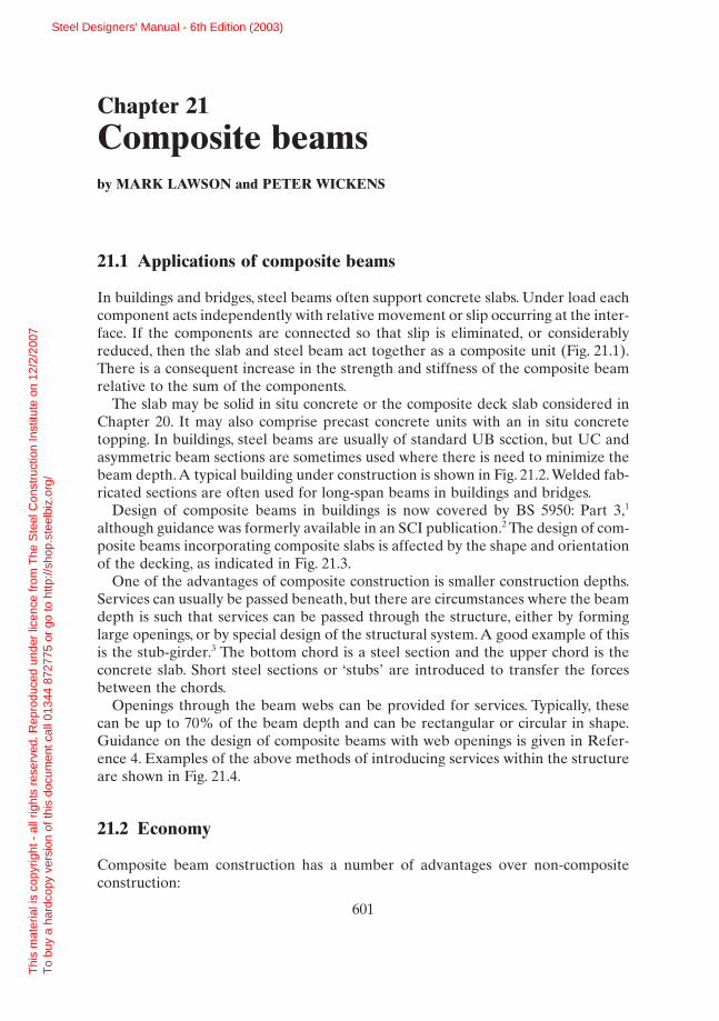
In buildings and bridges, steel beams often support concrete slabs. Under load eachcomponent acts independently with relative movement or slip occurring at the inter-face. If the components are connected so that slip is eliminated, or considerablyreduced, then the slab and steel beam act together as a composite unit (Fig. 21.1).There is a consequent increase in the strength and stiffness of the composite beamrelative to the sum of the components.
The slab may be solid in situ concrete or the composite deck slab considered inChapter 20. It may also comprise precast concrete units with an in situ concretetopping. In buildings, steel beams are usually of standard UB scction, but UC andasymmetric beam sections are sometimes used where there is need to minimize thebeam depth.A typical building under construction is shown in Fig. 21.2.Welded fab-ricated sections are often used for long-span beams in buildings and bridges.
Design of composite beams in buildings is now covered by BS 5950: Part 3,1
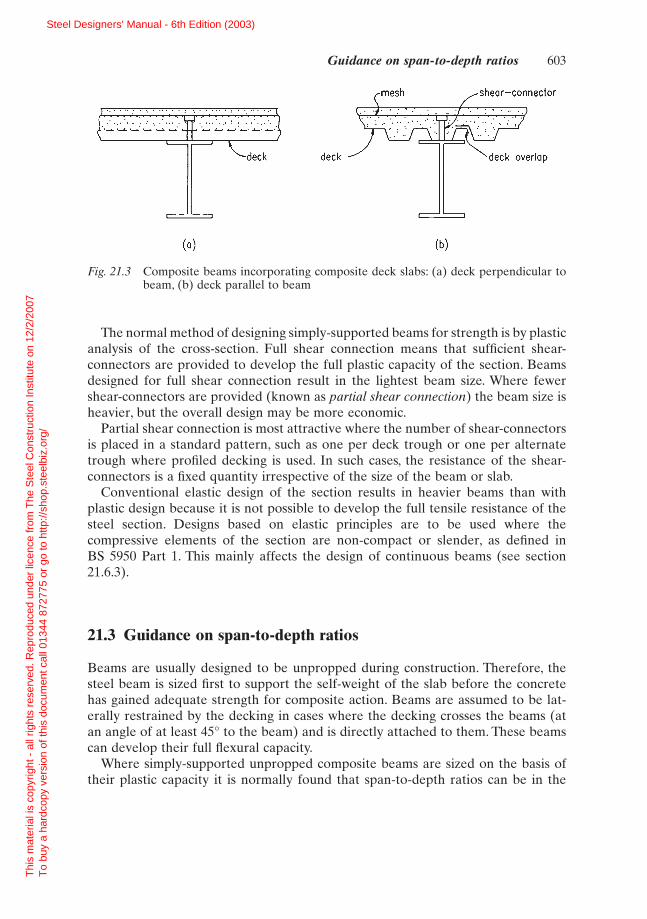
although guidance was formerly available in an SCI publication.2 The design of com-posite beams incorporating composite slabs is affected by the shape and orientationof the decking, as indicated in Fig. 21.3.
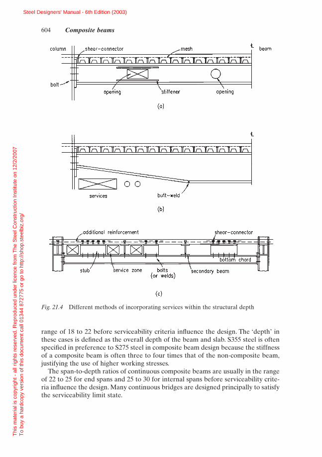
One of the advantages of composite construction is smaller construction depths.Services can usually be passed beneath, but there are circumstances where the beamdepth is such that services can be passed through the structure, either by forminglarge openings, or by special design of the structural system. A good example of thisis the stub-girder.3 The bottom chord is a steel section and the upper chord is theconcrete slab. Short steel sections or ‘stubs’ are introduced to transfer the forcesbetween the chords.
Openings through the beam webs can be provided for services. Typically, thesecan be up to 70% of the beam depth and can be rectangular or circular in shape.Guidance on the design of composite beams with web openings is given in Refer-ence 4. Examples of the above methods of introducing services within the structureare shown in Fig. 21.4.
21.2 Economy
Composite beam construction has a number of advantages over non-composite construction:
Steel Designers' Manual - 6th Edition (2003)
Thi
s m
ater
ial i
s co
pyrig
ht -
all
right
s re
serv
ed. R
epro
duce
d un
der
licen
ce fr
om T
he S
teel
Con
stru
ctio
n In
stitu
te o
n 12
/2/2
007
T
o bu
y a
hard
copy
ver
sion
of t
his
docu
men
t cal
l 013
44 8
7277
5 or
go
to h
ttp://
shop
.ste
elbi
z.or
g/
non—composite composite beambeam
support
force in
(1) savings in steel weight are typically 30% to 50% over non-composite beams.(2) the greater stiffness of the system means that beams can be shallower for the
same span, leading to lower storey heights and savings in cladding, etc.
It also shares the advantage of rapid construction.The main disadvantage is the need to provide shear-connectors at the interface
between the steel and concrete. There may also be an apparent increase in com-plexity of design. However, design tables have been presented to aid selection ofmember sizes.2
602 Composite beams
Fig. 21.1 Behaviour of composite and non-composite beams
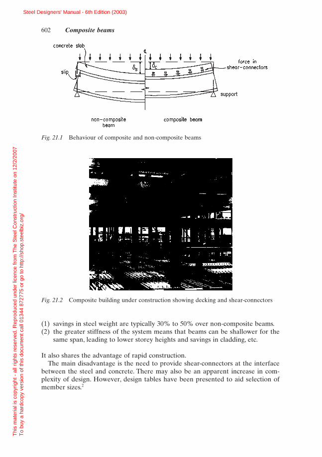
Fig. 21.2 Composite building under construction showing decking and shear-connectors
Steel Designers' Manual - 6th Edition (2003)
Thi
s m
ater
ial i
s co
pyrig
ht -
all
right
s re
serv
ed. R
epro
duce
d un
der
licen
ce fr
om T
he S
teel
Con
stru
ctio
n In
stitu
te o
n 12
/2/2
007
T
o bu
y a
hard
copy
ver
sion
of t
his
docu
men
t cal
l 013
44 8
7277
5 or
go
to h
ttp://
shop
.ste
elbi
z.or
g/
deck
(a) (b)
overlap
The normal method of designing simply-supported beams for strength is by plasticanalysis of the cross-section. Full shear connection means that sufficient shear-connectors are provided to develop the full plastic capacity of the section. Beamsdesigned for full shear connection result in the lightest beam size. Where fewershear-connectors are provided (known as partial shear connection) the beam size isheavier, but the overall design may be more economic.
Partial shear connection is most attractive where the number of shear-connectorsis placed in a standard pattern, such as one per deck trough or one per alternatetrough where profiled decking is used. In such cases, the resistance of the shear-connectors is a fixed quantity irrespective of the size of the beam or slab.
Conventional elastic design of the section results in heavier beams than withplastic design because it is not possible to develop the full tensile resistance of thesteel section. Designs based on elastic principles are to be used where the compressive elements of the section are non-compact or slender, as defined in BS 5950 Part 1. This mainly affects the design of continuous beams (see section21.6.3).
21.3 Guidance on span-to-depth ratios
Beams are usually designed to be unpropped during construction. Therefore, thesteel beam is sized first to support the self-weight of the slab before the concretehas gained adequate strength for composite action. Beams are assumed to be lat-erally restrained by the decking in cases where the decking crosses the beams (atan angle of at least 45° to the beam) and is directly attached to them. These beamscan develop their full flexural capacity.
Where simply-supported unpropped composite beams are sized on the basis oftheir plastic capacity it is normally found that span-to-depth ratios can be in the
Guidance on span-to-depth ratios 603
Fig. 21.3 Composite beams incorporating composite deck slabs: (a) deck perpendicular tobeam, (b) deck parallel to beam
Steel Designers' Manual - 6th Edition (2003)
Thi
s m
ater
ial i
s co
pyrig
ht -
all
right
s re
serv
ed. R
epro
duce
d un
der
licen
ce fr
om T
he S
teel
Con
stru
ctio
n In
stitu
te o
n 12
/2/2
007
T
o bu
y a
hard
copy
ver
sion
of t
his
docu
men
t cal
l 013
44 8
7277
5 or
go
to h
ttp://
shop
.ste
elbi
z.or
g/
column,shear—connector ._mesh beam
"sti1fener
(a)
(c)
boltE
I.opening
Qopening
L1 0°services
(b)
range of 18 to 22 before serviceability criteria influence the design. The ‘depth’ inthese cases is defined as the overall depth of the beam and slab. S355 steel is oftenspecified in preference to S275 steel in composite beam design because the stiffnessof a composite beam is often three to four times that of the non-composite beam,justifying the use of higher working stresses.
The span-to-depth ratios of continuous composite beams are usually in the rangeof 22 to 25 for end spans and 25 to 30 for internal spans before serviceability crite-ria influence the design. Many continuous bridges are designed principally to satisfythe serviceability limit state.
604 Composite beams
Fig. 21.4 Different methods of incorporating services within the structural depth
Steel Designers' Manual - 6th Edition (2003)
Thi
s m
ater
ial i
s co
pyrig
ht -
all
right
s re
serv
ed. R
epro
duce
d un
der
licen
ce fr
om T
he S
teel
Con
stru
ctio
n In
stitu
te o
n 12
/2/2
007
T
o bu
y a
hard
copy
ver
sion
of t
his
docu
men
t cal
l 013
44 8
7277
5 or
go
to h
ttp://
shop
.ste
elbi
z.or
g/

21.4 Types of shear connection
The modern form of shear-connector is the welded headed stud ranging in diameterfrom 13 to 25mm and from 65 to 125mm in height. The most popular size is 19mmdiameter and 100mm height before welding. When used with steel decking, studsare often welded through the decking using a hand tool connected via a control unitto a power generator. Each stud takes only a few seconds to weld in place. Alter-natively, the studs can be welded directly to the steel beams in the factory and thedecking butted up to or slotted over the studs.
There are, however, some limitations to through-deck welding: the top flange ofthe beam must not be painted, the galvanized steel should be less than around 1.25mm thick, the deck should be clean and free of moisture, and there should beno gap between the underside of the decking and the top of the beam.The minimumflange thickness must not be less than the diameter of the stud divided by 2.5 (typically, 19/2.5 = 7.6mm). The power generator needs 415V electrical supply, andthe maximum cable length between the weld gun and the power control units shouldbe limited to around 70m to avoid loss of power. Currently, only 13, 16 or 19mmdiameter studs can be through-deck welded on site.
Where precast concrete planks are used, the positions of the shear-connectors areusually such that they project through holes in the slab which are later filled withconcrete. Alternatively, a gap is left between the ends of the units sitting on the topflange of the beam on to which the shear connectors are fixed. Reinforcement(usually in the form of looped bars) is provided around the shear-connectors.
There is a range of other forms of welded shear-connector, but most lack prac-tical applications. The ‘bar and hoop’ and ‘channel’ welded shear-connectors havebeen use in bridge construction.5 Shot-fired shear-connectors may be used in smallerbuilding projects where site power might be a problem. All shear-connectors shouldbe capable of resisting uplift forces; hence the use of headed rather than plain studs.
The number of shear-connectors placed along the beam is usually sufficient todevelop the full flexural resistance of the member. However it is possible to reducethe number of shear-connectors in cases where the moment resistance exceeds theapplied moment and the shear-connectors have adequate ductility (or deformationcapacity). This is known as partial shear connection and is covered in section 21.7.4.
21.5 Span conditions
In buildings, composite beams are usually designed to be simply-supported, mainlyto simplify the design process, to reduce the complexity of the beam-to-column con-nections, and to minimize the amount of slab reinforcement and shear-connectorsthat are needed to develop continuity at the ultimate limit state.
However, there are ways in which continuity can be readily introduced, in orderto improve the stiffness of composite beams. Figure 21.5 shows how a typical con-nection detail at an internal column can be modified to develop continuity. The stub
Span conditions 605
Steel Designers' Manual - 6th Edition (2003)
Thi
s m
ater
ial i
s co
pyrig
ht -
all
right
s re
serv
ed. R
epro
duce
d un
der
licen
ce fr
om T
he S
teel
Con
stru
ctio
n In
stitu
te o
n 12
/2/2
007
T
o bu
y a
hard
copy
ver
sion
of t
his
docu
men
t cal
l 013
44 8
7277
5 or
go
to h
ttp://
shop
.ste
elbi
z.or
g/

Mbending momentram
M developed byshear—connectors
in this zone
tension in anchoragereinforcement lenath mesh- 7.,.
çIL-1I...., . .. ... ... ..;. -y t• ItI L
boltcompression
stiffener
girder system also utilizes continuity of the secondary members (see Fig. 21.4(c)).Other methods of continuous design are presented in References 3 and 6.
Continuous composite beams may be more economic than simply-supportedbeams where plastic hinge analysis of the continuous member is carried out, pro-vided the section is plastic according to BS 5950: Part 1. However, where the lowerflange or web of the beam is non-compact or slender in the negative (hogging)moment region, then elastic design must be used, both in terms of the distributionof moment along the beam, and also for analysis of the section. Lateral instabilityof the lower flange is an important design condition, although torsional restraint isdeveloped by the web of the section and the concrete slab.6
In bridges, continuity is often desirable for serviceability reasons, both to reducedeflections, and to minimize cracking of the concrete slab, finishes and wearingsurface in road bridges. Special features of composite construction appropriate tobridge design are covered in the publication by Johnson and Buckby7 based on BS 5400: Part 5.5
21.6 Analysis of composite section
21.6.1 Elastic analysis
Elastic analysis is employed in establishing the serviceability performance of com-posite beams, or the resistance of beams subject to the effect of instability, for
606 Composite beams
Fig. 21.5 Representation of conditions at internal column of continuous beam
Steel Designers' Manual - 6th Edition (2003)
Thi
s m
ater
ial i
s co
pyrig
ht -
all
right
s re
serv
ed. R
epro
duce
d un
der
licen
ce fr
om T
he S
teel
Con
stru
ctio
n In
stitu
te o
n 12
/2/2
007
T
o bu
y a
hard
copy
ver
sion
of t
his
docu
men
t cal
l 013
44 8
7277
5 or
go
to h
ttp://
shop
.ste
elbi
z.or
g/

Os
Be/ae
D
elastic
neutral axisequivalentsteel area
stress p
(a) (b)
example, in continuous construction, or in beams where the ductility of the shearconnection is not adequate.
The important properties of the section are the section modulus and the secondmoment of area. First it is necessary to determine the centroid (elastic neutral axis)of the transformed section by expressing the area of concrete in steel units by divid-ing the concrete area within the effective breadth of the slab, Be, by an appropriatemodular ratio (ratio of the elastic modulus of steel to concrete).
In unpropped construction, account is taken of the stresses induced in the non-composite section as well as the stresses in the composite section. In elastic analy-sis, therefore, the order of loading is important. For elastic conditions to hold,extreme fibre stresses are kept below their design values, and slip at the interfacebetween the concrete and steel should be negligible.
The elastic section properties are evaluated from the transformed section as inFig. 21.6. The term ae is the modular ratio. The area of concrete within the profiledepth is ignored (this is conservative where the decking troughs lie parallel to thebeam). The concrete can usually be assumed to be uncracked under positivemoment.
The elastic neutral axis depth, xe, below the upper surface of the slab is deter-mined from the formula:
(21.1)x
D Dr
DD
re
s pe s
e=
-+ +Ê
ˈ¯
+( )2 2
1
a
a
Analysis of composite section 607
Fig. 21.6 Elastic behaviour of composite beam. (a) Elastic stress distribution.(b) Transformed section
Steel Designers' Manual - 6th Edition (2003)
Thi
s m
ater
ial i
s co
pyrig
ht -
all
right
s re
serv
ed. R
epro
duce
d un
der
licen
ce fr
om T
he S
teel
Con
stru
ctio
n In
stitu
te o
n 12
/2/2
007
T
o bu
y a
hard
copy
ver
sion
of t
his
docu
men
t cal
l 013
44 8
7277
5 or
go
to h
ttp://
shop
.ste
elbi
z.or
g/
where r = A/[(Ds - Dp)Be], Ds is the slab depth, Dp is profile height (see Fig. 21.6)and A is the cross-sectional area of the beam of depth D.
The second moment of area of the uncracked composite section is:
(21.2)
where I is the second moment of area of the steel section. The section modulus forthe steel in tension is:
(21.3)
and for concrete in compression is:
(21.4)
The composite stiffness can be 3 to 5 times, and the section modulus 1.5 to 2.5 timesthat of the I-section alone.
21.6.2 Plastic analysis
The ultimate bending resistance of a composite section is determined from its plasticresistance. It is assumed that the strains across the section are sufficiently high thatthe steel stresses are at yield throughout the section and that the concrete stressesare at their design strength. The plastic stress blocks are therefore rectangular, asopposed to linear in elastic design.
The plastic moment resistance of the section is independent of the order ofloading (i.e. propped or unpropped construction) and is compared to the momentresulting from the total factored loading using the load factors in BS 5950: Part 1.
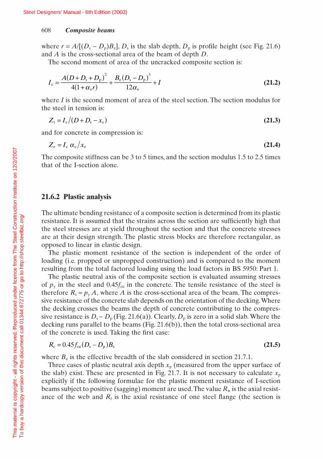
The plastic neutral axis of the composite section is evaluated assuming stressesof py in the steel and 0.45fcu in the concrete. The tensile resistance of the steel istherefore Rs = py A, where A is the cross-sectional area of the beam. The compres-sive resistance of the concrete slab depends on the orientation of the decking.Wherethe decking crosses the beams the depth of concrete contributing to the compres-sive resistance is Ds - Dp (Fig. 21.6(a)). Clearly, Dp is zero in a solid slab. Where thedecking runs parallel to the beams (Fig. 21.6(b)), then the total cross-sectional areaof the concrete is used. Taking the first case:
(21.5)
where Be is the effective breadth of the slab considered in section 21.7.1.Three cases of plastic neutral axis depth xp (measured from the upper surface of
the slab) exist. These are presented in Fig. 21.7. It is not necessary to calculate xp
explicitly if the following formulae for the plastic moment resistance of I-sectionbeams subject to positive (sagging) moment are used.The value Rw is the axial resist-ance of the web and Rf is the axial resistance of one steel flange (the section is
R f D D Bc cu s p e= -( )0 45.
Z I xe c e e= a
Z I D D xt c s e= + -( )
IA D D D
rB D D
Ics p
e
e s p
e=
+ +( )+( ) +
-( )+
2 3
4 1 12a a
608 Composite beams
Steel Designers' Manual - 6th Edition (2003)
Thi
s m
ater
ial i
s co
pyrig
ht -
all
right
s re
serv
ed. R
epro
duce
d un
der
licen
ce fr
om T
he S
teel
Con
stru
ctio
n In
stitu
te o
n 12
/2/2
007
T
o bu
y a
hard
copy
ver
sion
of t
his
docu
men
t cal
l 013
44 8
7277
5 or
go
to h
ttp://
shop
.ste
elbi
z.or
g/
py
O•451cu
assumed to be symmetrical). The top flange is considered to be fully restrained bythe concrete slab.
The moment resistance, Mpc, of the composite beam is given by:
Case 1: Rc > Rs (plastic neutral axis lies in concrete slab):
(21.6)
Case 2: Rs > Rc > Rw (plastic neutral axis lies in steel flange):
(21.7)
NB the last term in this expression is generally small (T is the flange thickness).
Case 3: Rc < Rw (plastic neutral axis lies in web):
(21.8)
where Ms is the plastic moment resistance of the steel section alone. This formulaassumes that the web is compact i.e. not subject to the effects of local buckling. Forthis to be true the depth of the web in compression should not exceed 78te, wheret is the web thickness (e is defined in BS 5950: Part 1). If the web is non-compact, amethod of determining the moment resistance of the section is given in BS 5950:Part 3, Appendix B.1
21.6.3 Continuous beams
Bending moments in continuous composite beams can be evaluated from elasticglobal analysis. However, these result in an overestimate of moments at the sup-ports because cracking of the concrete reduces the stiffness of the section and
M M RD D D R
RD
pc s cs p c
2
w= +
+ +ÊËÁ
ˆ¯̃ -
2 4
M RD
RD D R R
Rpc s cs p s c
f
T4
= ++Ê
ËÁˆ¯̃ -
-( )2 2
2
M RD
DRR
D Dpc s s
s
c
s p
2= + -
-ÊËÁ
ˆ¯̃
ÈÎÍ
˘˚̇2
Analysis of composite section 609
Fig. 21.7 Plastic analysis of composite section under positive (sagging) moment (PNA:plastic neutral axis)
Steel Designers' Manual - 6th Edition (2003)
Thi
s m
ater
ial i
s co
pyrig
ht -
all
right
s re
serv
ed. R
epro
duce
d un
der
licen
ce fr
om T
he S
teel
Con
stru
ctio
n In
stitu
te o
n 12
/2/2
007
T
o bu
y a
hard
copy
ver
sion
of t
his
docu
men
t cal
l 013
44 8
7277
5 or
go
to h
ttp://
shop
.ste
elbi
z.or
g/

permits a relaxation of bending moment. A simplified approach is to redistributethe support moment based on gross (uncracked) section properties by the amountsgiven in Table 21.1. Alternatively, moments can be determined using the appropri-ate cracked and uncracked stiffnesses in a frame analysis. In this case, the permit-ted redistribution of moment is less.
610 Composite beams
Table 21.1 Maximum redistribution of support moment based on elastic design of continuousbeams at the ultimate limit state
Classification of compression flange at supports
Assumed sectionPlastic
properties at Slender Semi-compact Compact Generally Beams (with nominalsupports slab reinforcement)
Gross uncracked 10% 20% 30% 40% 50%Cracked 0% 10% 20% 30% 30%
Table 21.2 Moment coefficients (multiplied by free moment of WL/8) for elastic design ofcontinuous beams
Classification of compression flange at supports
Plastic
Location Slender Semi-compact Compact Generally Beams (withnominal slab
reinforcement)
Middle 2 spans 0.71 0.71 0.71 0.75 0.79of end 3 or 0.80 0.80 0.80 0.80 0.82span more
spans
First 2 spans 0.91 0.81 0.71 0.61 0.50internal 3 or 0.86 0.76 0.67 0.57 0.48support more
spans
Middle of 0.65 0.65 0.65 0.65 0.67internal spansInternal supports 0.75 0.67 0.58 0.50 0.42(except first)
Redistribution 10% 20% 30% 40% 50%
The section classification is expressed in terms of the proportions of the com-pression (lower) flange at internal supports. This determines the permitted redistri-bution of moment. A special category of plastic section is introduced where thesection is of uniform shape throughout and nominal reinforcement is placed in theslab which does not contribute to the bending resistance of the beam. In this casethe maximum redistribution of moment under uniform loading is increased to 50%.A simplified elastic approach is to use the design moments in Table 21.2 assumingthat:
Steel Designers' Manual - 6th Edition (2003)
Thi
s m
ater
ial i
s co
pyrig
ht -
all
right
s re
serv
ed. R
epro
duce
d un
der
licen
ce fr
om T
he S
teel
Con
stru
ctio
n In
stitu
te o
n 12
/2/2
007
T
o bu
y a
hard
copy
ver
sion
of t
his
docu
men
t cal
l 013
44 8
7277
5 or
go
to h
ttp://
shop
.ste
elbi
z.or
g/

(1) the unfactored imposed load does not exceed twice the unfactored dead load;(2) the load is uniformly distributed;(3) end spans do not exceed 115% of the length of the adjacent span;(4) adjacent spans do not differ in length by more than 25% of the longer span.
An alternative to the elastic approach is plastic hinge analysis of plastic sections.Conditions on the use of plastic hinge analysis are presented in BS 5950: Part 31 andEurocode 4 (draft).8 However, large redistributions of moment may adversely affectserviceability behaviour (see section 21.7.8).
The ultimate load resistance of a continuous beam under positive (sagging)moment is determined as for a simply-supported beam. The effective breadth of theslab is based on the effective span of the beam under positive moment (see section21.7.1).The number of shear-connectors contributing to the positive moment capac-ity is ascertained knowing the point of contraflexure.
The negative (hogging) moment resistance of a continuous beam or cantilevershould be based on the steel section together with any properly anchored tensionreinforcement within the effective breadth of the slab. This poses problems at edgecolumns, where it may be prudent to neglect the effect of the reinforcement unlessparticular measures are taken to provide this anchorage. The behaviour of a con-tinuous beam is represented in Fig. 21.5.
The negative moment resistance is evaluated from plastic analysis of the section:
Case 1: Rr < Rw (plastic neutral axis lies in web):
(21.9)
where Rr is the tensile resistance of the reinforcement over width Be, Rq is the capac-ity of the shear-connectors between the point of contraflexure and the point ofmaximum negative moment (see section 21.7.3), and Dr is the height of the re-inforcement above the top of the beam.
Case 2: Rr > Rw (plastic neutral axis lies in flange):
(21.10)
NB the last term in this expression is generally small.The formulae assume that the web and lower flange are compact i.e. not subject
to the effects of local buckling. The limiting depth of the web in compression is 78te(where e is defined in Chapter 2) and the limiting breath : thickness ratio of theflange is defined in Table 11 of BS 5950: Part 1.
If these limiting slendernesses are exceeded then the section is designed elasti-cally – often the situation in bridge design.The appropriate effective breadth of slabis used because of the sensitivity of the position of the elastic neutral axis and hencethe zone of the web in compression to the tensile force transferred by the rein-forcement.The elastic section properties are determined on the assumption that theconcrete is cracked and does not contribute to the resistance of the section.
M RD
R DR R
RT
snc r rs r
f= + -
-( )2 4
2
M M RD
DRR
Dnc s s r
q2
w= + +Ê
ˈ¯ -
2 4
Analysis of composite section 611
Steel Designers' Manual - 6th Edition (2003)
Thi
s m
ater
ial i
s co
pyrig
ht -
all
right
s re
serv
ed. R
epro
duce
d un
der
licen
ce fr
om T
he S
teel
Con
stru
ctio
n In
stitu
te o
n 12
/2/2
007
T
o bu
y a
hard
copy
ver
sion
of t
his
docu
men
t cal
l 013
44 8
7277
5 or
go
to h
ttp://
shop
.ste
elbi
z.or
g/

point loadudi
B/L
0.8
0.2
0.3
0.6 _B
0.40.4
0.6
0.2— — 0.8
support mid—span support
21.7 Basic design
21.7.1 Effective breadths
The structural system of a composite floor or bridge deck is essentially a series ofparallel T beams with wide thin flanges. In such a system the contribution of theconcrete flange in compression is limited because of the influence of ‘shear lag’. Thechange in longitudinal stress is associated with in-plane shear strains in the flanges.
The ratio of the effective breadth of the slab to the actual breadth (Be/B) is afunction of the type of loading, the support conditions and the cross-section underconsideration as illustrated in Fig. 21.8.The effective breadth of slab is therefore nota precise figure but approximations are justified. A common approach in plasticdesign is to consider the effective breadth as a proportion (typically 20%–33%) ofthe beam span.This is because the conditions at failure are different from the elasticconditions used in determining the data in Fig. 21.8, and the plastic bending capac-ity of a composite section is relatively insensitive to the precise value of effectivebreadth used.
Eurocode 4 (in its ENV or pre-norm version)8 and BS 5950: Part 31 define theeffective breadth as (span/4) (half on each side of the beam) but not exceeding theactual slab breadth considered to act with each beam. Where profiled decking spansin the same direction as the beams, as in Fig. 21.3(b), allowance is made for the com-bined flexural action of the composite slab and the composite beam by limiting theeffective breadth to 80% of the actual breadth.
In building design, the same effective breadth is used for section analysis at boththe ultimate and serviceability limit states. In bridge design to BS 5400: Part 5,5
tabular data of effective breadths are given for elastic design at the serviceability
612 Composite beams
Fig. 21.8 Variation of effective breadth along beam and with loading
Steel Designers' Manual - 6th Edition (2003)
Thi
s m
ater
ial i
s co
pyrig
ht -
all
right
s re
serv
ed. R
epro
duce
d un
der
licen
ce fr
om T
he S
teel
Con
stru
ctio
n In
stitu
te o
n 12
/2/2
007
T
o bu
y a
hard
copy
ver
sion
of t
his
docu
men
t cal
l 013
44 8
7277
5 or
go
to h
ttp://
shop
.ste
elbi
z.or
g/
limit state. If plastic design is appropriate, the effective breadth is modified to(span/3).5
In the design of continuous beams, the effective breadth of the slab may be basedconservatively on the effective span of the beam subject to positive or negativemoment. For positive moment, the effective breadth is 0.25 times 0.7 span, and fornegative moment, the effective breadth is 0.25 times 0.25 times the sum of the adja-cent spans. These effective breadths reduce to 0.175 span and 0.125 span respec-tively for positive and negative moment regions of equal-span beams.
21.7.2 Modular ratio
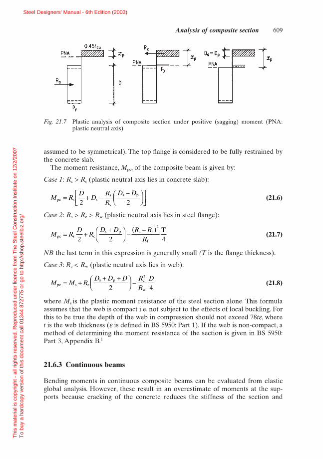
The modular ratio is the ratio of the elastic modulus of steel to the creep-modifiedmodulus of concrete, which depends on the duration of the load. The short- andlong-term modular ratios given in Table 21.3 may be used for all grades of concrete.The effective modular ratio used in design should be related to the proportions ofthe loading that are considered to be of short- and long-term duration. Typicalvalues used for office buildings are 10 for normal weight and 15 for lightweight con-crete.
21.7.3 Shear connection
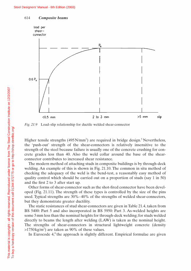
The shear resistance of shear-connectors is established by the push-out test, a stan-dard test using a solid slab. A typical load–slip curve for a welded stud is shown inFig. 21.9. The loading portion can be assumed to follow an empirical curve.9 Thestrength plateau is reached at a slip of 2–3mm.
The shear resistance of shear-connectors is a function of the concrete strength,connector type and the weld, related to the diameter of the connector. The purposeof the head of the stud is to prevent uplift. The common diameter of stud which canbe welded easily on site is 19mm, supplied in 75mm, 100mm or 125mm heights.Thematerial properties, before forming, are typically:
Ultimate tensile strength 450N/mm2
Elongation at failure 15%
Basic design 613
Table 21.3 Modular ratios (ae) of steel of concrete
Duration of loading
Type of concrete Short-term Long-term ‘Office’ loading
Normal weight 6 18 10
Lightweight 10 25 15(density > 1750kg/m3)
Steel Designers' Manual - 6th Edition (2003)
Thi
s m
ater
ial i
s co
pyrig
ht -
all
right
s re
serv
ed. R
epro
duce
d un
der
licen
ce fr
om T
he S
teel
Con
stru
ctio
n In
stitu
te o
n 12
/2/2
007
T
o bu
y a
hard
copy
ver
sion
of t
his
docu
men
t cal
l 013
44 8
7277
5 or
go
to h
ttp://
shop
.ste
elbi
z.or
g/
load pershear—
connector
0.6 u
<0.5 mm 2 to 3 mm >5 mm slip
Higher tensile strengths (495N/mm2) are required in bridge design.5 Nevertheless,the ‘push-out’ strength of the shear-connectors is relatively insensitive to thestrength of the steel because failure is usually one of the concrete crushing for con-crete grades less than 40. Also the weld collar around the base of the shear-connector contributes to increased shear resistance.
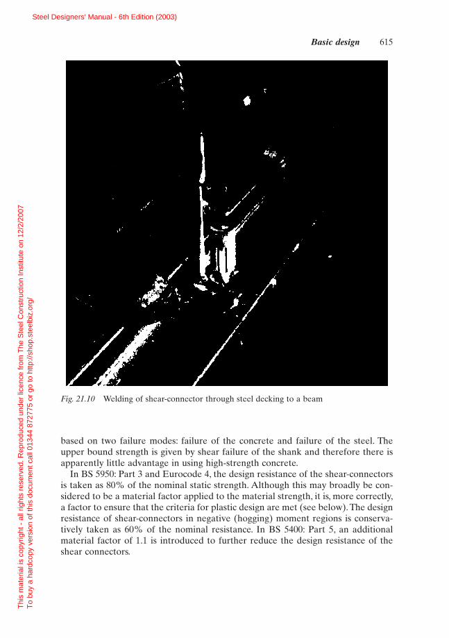
The modern method of attaching studs in composite buildings is by through-deckwelding. An example of this is shown in Fig. 21.10. The common in situ method ofchecking the adequacy of the weld is the bend-test, a reasonably easy method ofquality control which should be carried out on a proportion of studs (say 1 in 50)and the first 2 to 3 after start up.
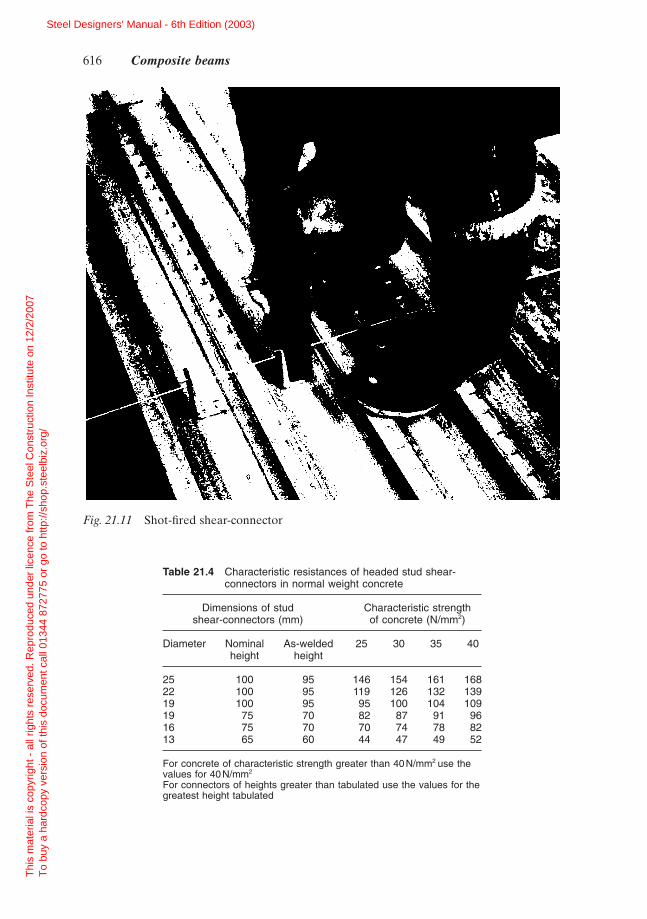
Other forms of shear-connector such as the shot-fired connector have been devel-oped (Fig. 21.11). The strength of these types is controlled by the size of the pinsused. Typical strengths are 30%–40% of the strengths of welded shear-connectors,but they demonstrate greater ductility.
The static resistances of stud shear-connectors are given in Table 21.4, taken fromBS 5400: Part 5 and also incorporated in BS 5950: Part 3. As-welded heights aresome 5mm less than the nominal heights for through-deck welding; for studs weldeddirectly to beams the length after welding (LAW) is taken as the nominal height.The strengths of shear-connectors in structural lightweight concrete (density >1750kg/m2) are taken as 90% of these values.
In Eurocode 4,8 the approach is slightly different. Empirical formulae are given
614 Composite beams
Fig. 21.9 Load–slip relationship for ductile welded shear-connector
Steel Designers' Manual - 6th Edition (2003)
Thi
s m
ater
ial i
s co
pyrig
ht -
all
right
s re
serv
ed. R
epro
duce
d un
der
licen
ce fr
om T
he S
teel
Con
stru
ctio
n In
stitu
te o
n 12
/2/2
007
T
o bu
y a
hard
copy
ver
sion
of t
his
docu
men
t cal
l 013
44 8
7277
5 or
go
to h
ttp://
shop
.ste
elbi
z.or
g/
based on two failure modes: failure of the concrete and failure of the steel. Theupper bound strength is given by shear failure of the shank and therefore there isapparently little advantage in using high-strength concrete.
In BS 5950: Part 3 and Eurocode 4, the design resistance of the shear-connectorsis taken as 80% of the nominal static strength. Although this may broadly be con-sidered to be a material factor applied to the material strength, it is, more correctly,a factor to ensure that the criteria for plastic design are met (see below). The designresistance of shear-connectors in negative (hogging) moment regions is conserva-tively taken as 60% of the nominal resistance. In BS 5400: Part 5, an additionalmaterial factor of 1.1 is introduced to further reduce the design resistance of theshear connectors.
Basic design 615
Fig. 21.10 Welding of shear-connector through steel decking to a beam
Steel Designers' Manual - 6th Edition (2003)
Thi
s m
ater
ial i
s co
pyrig
ht -
all
right
s re
serv
ed. R
epro
duce
d un
der
licen
ce fr
om T
he S
teel
Con
stru
ctio
n In
stitu
te o
n 12
/2/2
007
T
o bu
y a
hard
copy
ver
sion
of t
his
docu
men
t cal
l 013
44 8
7277
5 or
go
to h
ttp://
shop
.ste
elbi
z.or
g/
616 Composite beams
Fig. 21.11 Shot-fired shear-connector
Table 21.4 Characteristic resistances of headed stud shear-connectors in normal weight concrete
Dimensions of stud Characteristic strengthshear-connectors (mm) of concrete (N/mm2)
Diameter Nominal As-welded 25 30 35 40height height
25 100 95 146 154 161 16822 100 95 119 126 132 13919 100 95 95 100 104 10919 75 70 82 87 91 9616 75 70 70 74 78 8213 65 60 44 47 49 52
For concrete of characteristic strength greater than 40N/mm2 use thevalues for 40N/mm2
For connectors of heights greater than tabulated use the values for thegreatest height tabulated
Steel Designers' Manual - 6th Edition (2003)
Thi
s m
ater
ial i
s co
pyrig
ht -
all
right
s re
serv
ed. R
epro
duce
d un
der
licen
ce fr
om T
he S
teel
Con
stru
ctio
n In
stitu
te o
n 12
/2/2
007
T
o bu
y a
hard
copy
ver
sion
of t
his
docu
men
t cal
l 013
44 8
7277
5 or
go
to h
ttp://
shop
.ste
elbi
z.or
g/
loading
shear—connector
elastic shear flow
actual shear flow at failure
idealized plastic shear flow
slip
In plastic design, it is important to ensure that the shear-connectors display adequate ductility. It may be expected that shear-connectors maintain their designresistances at displacements of up to 5mm. A possible exception is where concretestrengths exceed C 40, as the form of failure may be more brittle.
For beams subject to uniform load, the degree of shear connection that is pro-vided by uniformly-spaced shear-connectors (defined in section 21.7.4) reducesmore rapidly than the applied moment away from the point of maximum moment.To ensure that the shear connection is adequate at all points along the beam, thedesign resistance of the shear-connectors is taken as 80% of their static resistance.This also partly ensures that flexural failure will occur before shear failure. Forbeams subject to point loads, it is necessary to design for the appropriate shear con-nection at each major load point.
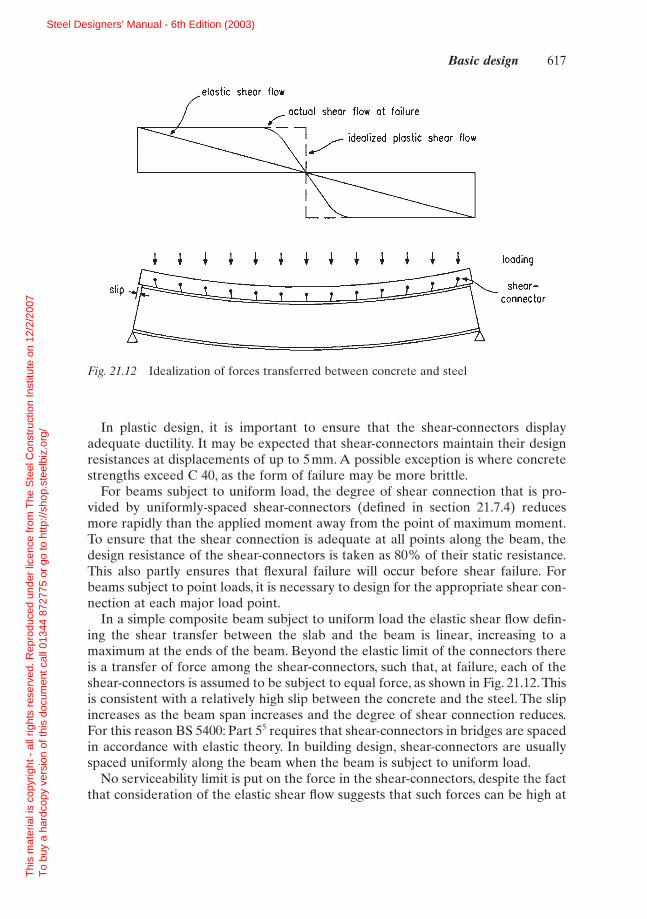
In a simple composite beam subject to uniform load the elastic shear flow defin-ing the shear transfer between the slab and the beam is linear, increasing to amaximum at the ends of the beam. Beyond the elastic limit of the connectors thereis a transfer of force among the shear-connectors, such that, at failure, each of theshear-connectors is assumed to be subject to equal force, as shown in Fig. 21.12. Thisis consistent with a relatively high slip between the concrete and the steel. The slipincreases as the beam span increases and the degree of shear connection reduces.For this reason BS 5400: Part 55 requires that shear-connectors in bridges are spacedin accordance with elastic theory. In building design, shear-connectors are usuallyspaced uniformly along the beam when the beam is subject to uniform load.
No serviceability limit is put on the force in the shear-connectors, despite the factthat consideration of the elastic shear flow suggests that such forces can be high at
Basic design 617
Fig. 21.12 Idealization of forces transferred between concrete and steel
Steel Designers' Manual - 6th Edition (2003)
Thi
s m
ater
ial i
s co
pyrig
ht -
all
right
s re
serv
ed. R
epro
duce
d un
der
licen
ce fr
om T
he S
teel
Con
stru
ctio
n In
stitu
te o
n 12
/2/2
007
T
o bu
y a
hard
copy
ver
sion
of t
his
docu
men
t cal
l 013
44 8
7277
5 or
go
to h
ttp://
shop
.ste
elbi
z.or
g/
working load.This is reflected in the effect of slip on deflection in cases where partialshear connection is used. When designing bridges5 or structures subject to fatigueloading, a limit of 55% of the design resistance of the shear-connectors is appro-priate for design at the serviceability limit state.
21.7.4 Partial shear connection
In plastic design of composite beams the longitudinal shear force to be transferredbetween the concrete and the steel is the lesser of Rc and Rs. The number of shear-connectors placed along the beam between the points of zero and maximum posi-tive moment should be sufficient to transfer this force.
In cases where fewer shear-connectors are provided than the number requiredfor full shear connection it is not possible to develop Mpc. If the total capacity of theshear-connectors between the points of zero and maximum moment is Rq (less thanthe smaller of Rs and Rc), then the stress block method in section 21.6.2 is modifiedas follows, to determine the moment resistance, Mc:
Case 4: Rq > Rw (plastic neutral axis lies in flange):
(21.11)
NB the last term in this expression is generally small.
Case 5: Rq < Rw (plastic neutral axis lies in web):
(21.12)
The formulae are obtained by replacing Rc by Rq and re-evaluating the neutral axisposition. The method is similar to that used in the American method of plasticdesign,10 which predicts a non-linear increase of moment capacity with degree ofshear connection K defined as:
An alternative approach, which has proved attractive, is to define the moment resist-ance in terms of a simple linear interaction of the form:
(21.13)
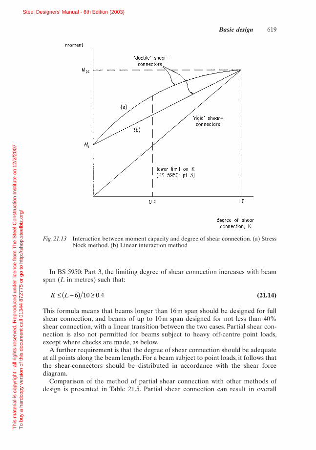
The stress block and linear interaction methods are presented in Fig. 21.13 for atypical beam. It can be seen that there is a significant benefit in the stress blockmethod in the important range of K = 0.5 to 0.7.
In using methods based on partial shear connection a lower limit for K of 0.4 isspecified. This is to overcome any adverse effects arising from the limited defor-mation capacity of the shear-connectors.
M M K M Mc s pc s= + -( )
K R R R R
K R R R R
= <= <
q s s c
q c c s
for
or for
M M RD
DRR
D D RR
Dc s q s
q
c
s p q2
w= + + -
-ÊËÁ
ˆ¯̃
ÈÎÍ
˘˚̇
-2 2 4
M RD
R DRR
D D R RR
Tc s q s
q
c
s p s q
f= + -
-ÊËÁ
ˆ¯̃
ÈÎÍ
˘˚̇
--( )
2 2 4
2
618 Composite beams
Steel Designers' Manual - 6th Edition (2003)
Thi
s m
ater
ial i
s co
pyrig
ht -
all
right
s re
serv
ed. R
epro
duce
d un
der
licen
ce fr
om T
he S
teel
Con
stru
ctio
n In
stitu
te o
n 12
/2/2
007
T
o bu
y a
hard
copy
ver
sion
of t
his
docu
men
t cal
l 013
44 8
7277
5 or
go
to h
ttp://
shop
.ste
elbi
z.or
g/
moment
'ductile shear—
rigid shear—connectors
K
3)
0.4 1.0
degree of shearconnection, K
In BS 5950: Part 3, the limiting degree of shear connection increases with beamspan (L in metres) such that:
(21.14)
This formula means that beams longer than 16m span should be designed for fullshear connection, and beams of up to 10m span designed for not less than 40%shear connection, with a linear transition between the two cases. Partial shear con-nection is also not permitted for beams subject to heavy off-centre point loads,except where checks are made, as below.
A further requirement is that the degree of shear connection should be adequateat all points along the beam length. For a beam subject to point loads, it follows thatthe shear-connectors should be distributed in accordance with the shear forcediagram.
Comparison of the method of partial shear connection with other methods ofdesign is presented in Table 21.5. Partial shear connection can result in overall
K L£ -( ) ≥6 10 0 4.
Basic design 619
Fig. 21.13 Interaction between moment capacity and degree of shear connection. (a) Stressblock method. (b) Linear interaction method
Steel Designers' Manual - 6th Edition (2003)
Thi
s m
ater
ial i
s co
pyrig
ht -
all
right
s re
serv
ed. R
epro
duce
d un
der
licen
ce fr
om T
he S
teel
Con
stru
ctio
n In
stitu
te o
n 12
/2/2
007
T
o bu
y a
hard
copy
ver
sion
of t
his
docu
men
t cal
l 013
44 8
7277
5 or
go
to h
ttp://
shop
.ste
elbi
z.or
g/
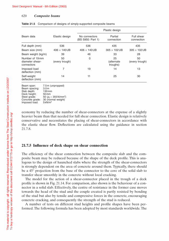
economy by reducing the number of shear-connectors at the expense of a slightlyheavier beam than that needed for full shear connection. Elastic design is relativelyconservative and necessitates the placing of shear-connectors in accordance with the elastic shear flow. Deflections are calculated using the guidance in section 21.7.8.
21.7.5 Influence of deck shape on shear connection
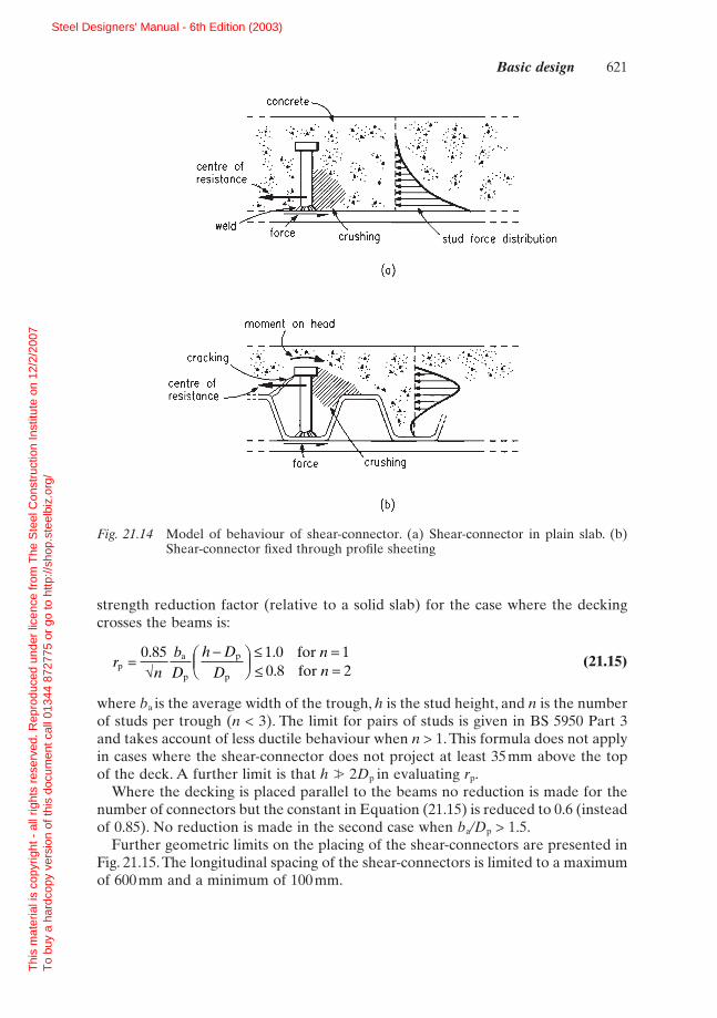
The efficiency of the shear connection between the composite slab and the com-posite beam may be reduced because of the shape of the deck profile. This is ana-logous to the design of haunched slabs where the strength of the shear-connectorsis strongly dependent on the area of concrete around them. Typically, there shouldbe a 45° projection from the base of the connector to the core of the solid slab totransfer shear smoothly in the concrete without local cracking.
The model for the action of a shear-connector placed in the trough of a deckprofile is shown in Fig. 21.14. For comparison, also shown is the behaviour of a con-nector in a solid slab. Effectively, the centre of resistance in the former case movestowards the head of the stud and the couple created is partly resisted by bendingof the stud but also by tensile and compressive forces in the concrete, encouragingconcrete cracking, and consequently the strength of the stud is reduced.
A number of tests on different stud heights and profile shapes have been per-formed. The following formula has been adopted by most standards worldwide. The
620 Composite beams
Table 21.5 Comparison of designs of simply-supported composite beams
Plastic design
Beam data Elastic design No connectors Partial Full shear(BS 5950: Part 1) connection connection
Full depth (mm) 536 536 435 435
Beam size (mm) 406 ¥ 140UB 406 ¥ 140UB 305 ¥ 102UB 305 ¥ 102UB
Beam weight (kg/m) 39 46 33 28
Number of 19mm 50 0 25 50diameter shear- (every trough) (alternate (every trough)connectors troughs)
Imposed load 7 19 14 13deflection (mm)
Self-weight 14 11 25 30deflection (mm)
Beam span: 7.5m (unpropped)Beam spacing: 3.0mSlab depth: 130mmDeck height: 50mmSteel grade: 50 (py = 355N/mm2)Concrete grade: 30 (normal weight)Imposed load: 5kN/m2
Steel Designers' Manual - 6th Edition (2003)
Thi
s m
ater
ial i
s co
pyrig
ht -
all
right
s re
serv
ed. R
epro
duce
d un
der
licen
ce fr
om T
he S
teel
Con
stru
ctio
n In
stitu
te o
n 12
/2/2
007
T
o bu
y a
hard
copy
ver
sion
of t
his
docu
men
t cal
l 013
44 8
7277
5 or
go
to h
ttp://
shop
.ste
elbi
z.or
g/
a
C
a.
0 Cb
II gI
I ;:
. C
- C
0
- av
a.
strength reduction factor (relative to a solid slab) for the case where the deckingcrosses the beams is:
(21.15)
where ba is the average width of the trough, h is the stud height, and n is the numberof studs per trough (n < 3). The limit for pairs of studs is given in BS 5950 Part 3and takes account of less ductile behaviour when n > 1. This formula does not applyin cases where the shear-connector does not project at least 35 mm above the topof the deck. A further limit is that h � 2Dp in evaluating rp.
Where the decking is placed parallel to the beams no reduction is made for thenumber of connectors but the constant in Equation (21.15) is reduced to 0.6 (insteadof 0.85). No reduction is made in the second case when ba/Dp > 1.5.
Further geometric limits on the placing of the shear-connectors are presented inFig. 21.15. The longitudinal spacing of the shear-connectors is limited to a maximumof 600mm and a minimum of 100mm.
rn
bD
h DD
nnp
a
p
p
p
for for
=-Ê
ËÁˆ¯̃
£ =£ =
0 85 1 0 10 8 2
. ..÷
Basic design 621
Fig. 21.14 Model of behaviour of shear-connector. (a) Shear-connector in plain slab. (b)Shear-connector fixed through profile sheeting
Steel Designers' Manual - 6th Edition (2003)
Thi
s m
ater
ial i
s co
pyrig
ht -
all
right
s re
serv
ed. R
epro
duce
d un
der
licen
ce fr
om T
he S
teel
Con
stru
ctio
n In
stitu
te o
n 12
/2/2
007
T
o bu
y a
hard
copy
ver
sion
of t
his
docu
men
t cal
l 013
44 8
7277
5 or
go
to h
ttp://
shop
.ste
elbi
z.or
g/
minimumdimensionsunless stated
100 mmII 1
• loopedbars:
slabedge
25 mm or 1.250.
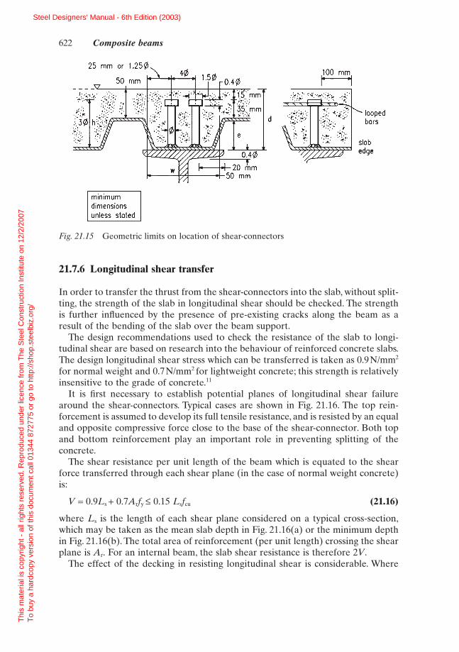
21.7.6 Longitudinal shear transfer
In order to transfer the thrust from the shear-connectors into the slab, without split-ting, the strength of the slab in longitudinal shear should be checked. The strengthis further influenced by the presence of pre-existing cracks along the beam as aresult of the bending of the slab over the beam support.
The design recommendations used to check the resistance of the slab to longi-tudinal shear are based on research into the behaviour of reinforced concrete slabs.The design longitudinal shear stress which can be transferred is taken as 0.9N/mm2
for normal weight and 0.7N/mm2 for lightweight concrete; this strength is relativelyinsensitive to the grade of concrete.11
It is first necessary to establish potential planes of longitudinal shear failurearound the shear-connectors. Typical cases are shown in Fig. 21.16. The top rein-forcement is assumed to develop its full tensile resistance, and is resisted by an equaland opposite compressive force close to the base of the shear-connector. Both topand bottom reinforcement play an important role in preventing splitting of the concrete.
The shear resistance per unit length of the beam which is equated to the shearforce transferred through each shear plane (in the case of normal weight concrete)is:
V = 0.9Ls + 0.7Arfy £ 0.15 Lsfcu (21.16)
where Ls is the length of each shear plane considered on a typical cross-section,which may be taken as the mean slab depth in Fig. 21.16(a) or the minimum depthin Fig. 21.16(b). The total area of reinforcement (per unit length) crossing the shearplane is Ar. For an internal beam, the slab shear resistance is therefore 2V.
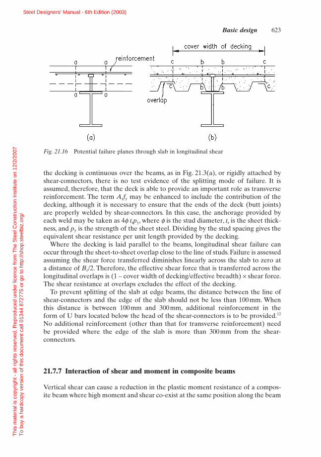
The effect of the decking in resisting longitudinal shear is considerable. Where
622 Composite beams
Fig. 21.15 Geometric limits on location of shear-connectors
Steel Designers' Manual - 6th Edition (2003)
Thi
s m
ater
ial i
s co
pyrig
ht -
all
right
s re
serv
ed. R
epro
duce
d un
der
licen
ce fr
om T
he S
teel
Con
stru
ctio
n In
stitu
te o
n 12
/2/2
007
T
o bu
y a
hard
copy
ver
sion
of t
his
docu
men
t cal
l 013
44 8
7277
5 or
go
to h
ttp://
shop
.ste
elbi
z.or
g/
cover width of decking
C b b_______
aoverlap
(a) (b)
a a
a
the decking is continuous over the beams, as in Fig. 21.3(a), or rigidly attached byshear-connectors, there is no test evidence of the splitting mode of failure. It isassumed, therefore, that the deck is able to provide an important role as transversereinforcement. The term Arfy may be enhanced to include the contribution of thedecking, although it is necessary to ensure that the ends of the deck (butt joints)are properly welded by shear-connectors. In this case, the anchorage provided byeach weld may be taken as 4f tspy, where f is the stud diameter, ts is the sheet thick-ness, and py is the strength of the sheet steel. Dividing by the stud spacing gives theequivalent shear resistance per unit length provided by the decking.
Where the decking is laid parallel to the beams, longitudinal shear failure canoccur through the sheet-to-sheet overlap close to the line of studs. Failure is assessedassuming the shear force transferred diminishes linearly across the slab to zero ata distance of Bc/2. Therefore, the effective shear force that is transferred across thelongitudinal overlaps is (1 – cover width of decking/effective breadth) ¥ shear force.The shear resistance at overlaps excludes the effect of the decking.
To prevent splitting of the slab at edge beams, the distance between the line ofshear-connectors and the edge of the slab should not be less than 100mm. Whenthis distance is between 100mm and 300mm, additional reinforcement in the form of U bars located below the head of the shear-connectors is to be provided.12
No additional reinforcement (other than that for transverse reinforcement) needbe provided where the edge of the slab is more than 300mm from the shear-connectors.
21.7.7 Interaction of shear and moment in composite beams
Vertical shear can cause a reduction in the plastic moment resistance of a compos-ite beam where high moment and shear co-exist at the same position along the beam
Basic design 623
Fig. 21.16 Potential failure planes through slab in longitudinal shear
Steel Designers' Manual - 6th Edition (2003)
Thi
s m
ater
ial i
s co
pyrig
ht -
all
right
s re
serv
ed. R
epro
duce
d un
der
licen
ce fr
om T
he S
teel
Con
stru
ctio
n In
stitu
te o
n 12
/2/2
007
T
o bu
y a
hard
copy
ver
sion
of t
his
docu
men
t cal
l 013
44 8
7277
5 or
go
to h
ttp://
shop
.ste
elbi
z.or
g/

shearforce
moment
O5P
(i.e. the beam is subject to one or two point loads).Where the shear force Fv exceeds0.5Pv (where Pv is the lesser of the shear resistance and the shear buckling resist-ance, determined from Part 1 of BS 5950), the reduced moment resistance is deter-mined from:
(21.17)
where Mc is the plastic moment resistance of the composite section, and Mf is theplastic moment resistance of the composite section having deducted the shear area(i.e. the web of the section).
The interaction is presented diagrammatically in Fig. 21.17. A quadratic relation-ship has been used, as opposed to the linear relationship in BS 5950: Part 1, becauseof its better agreement with test data, and because of the need for greater economyin composite sections which are often more highly stressed in shear than non-composite beams.
21.7.8 Deflections
Deflection limits for beams are specified in BS 5950: Part 1. Composite beams are,by their nature, shallower than non-composite beams and often are used in struc-tures where long spans would otherwise be uneconomic. As spans increase, so tra-
M M M M F Pccv c f v v= - -( ) -( )2 12
624 Composite beams
Fig. 21.17 Interaction between moment and shear
Steel Designers' Manual - 6th Edition (2003)
Thi
s m
ater
ial i
s co
pyrig
ht -
all
right
s re
serv
ed. R
epro
duce
d un
der
licen
ce fr
om T
he S
teel
Con
stru
ctio
n In
stitu
te o
n 12
/2/2
007
T
o bu
y a
hard
copy
ver
sion
of t
his
docu
men
t cal
l 013
44 8
7277
5 or
go
to h
ttp://
shop
.ste
elbi
z.or
g/
ditional deflection limits based on a proportion of the beam span may not be appro-priate. The absolute deflection may also be important and pre-cambering may needto be considered for beams longer than 10m.
Elastic section properties, as described in section 21.6.1, are used in establishingthe deflection of composite beams. Uncracked section properties are considered tobe appropriate for deflection calculations. The appropriate modular ratio is used,but it is usually found that the section properties are relatively insensitive to theprecise value of modular ratio. The effective breadth of the slab is the same as thatused in evaluating the bending resistance of the beam.
The deflection of a simple composite beam at working load, where partial shearconnection is used, can be calculated from:13
(21.18)
where dc and ds are the deflections of the composite and steel beam respectively atthe appropriate serviceability load; K is the degree of shear connection used in thedetermining of the plastic strength of the beam (section 21.7.4). The differencebetween the coefficients in these two formulae arises from the different shear-connector forces and hence slip at serviceability loads in the two cases. These for-mulae are conservative with respect to other guidance.10
The effect of continuity in composite beams may be considered as follows. Theimposed load deflection at mid-span of a continuous beam under uniform load orsymmetric point loads may be determined from the approximate formula:
(1.19)
where d ¢c is the deflection of the simply-supported composite beam for the sameloading conditions; M0 is the maximum moment in a simply-supported beam subjectto the same loads; M1 and M2 are the end moments at the adjacent supports of thespan of the continuous beam under consideration.
To determine appropriate values of M1 and M2, an elastic global analysis is carriedout using the flexural stiffness of the uncracked section.
For buildings of normal usage, these support moments are reduced to take intoaccount the effect of pattern loading and concrete cracking. The redistribution ofsupport moment under imposed load should be taken as the same as that used atthe ultimate limit state (see Table 21.1), but not less than 30%.
For buildings subject to semi-permanent or variable loads (e.g. warehouses), thereis a possibility of alternating plasticity under repeated loading leading to greaterimposed load deflections. This also affects the design of continuous beams designedby plastic hinge analysis, where the effective redistribution of support momentexceeds 50%. In such cases a more detailed analysis should be carried out consid-ering these effects (commonly referred to as ‘shakedown’) as follows:
(1) evaluate the support moments based on elastic analysis of the continuous beamunder a first loading cycle of dead load and 80% imposed load (or 100% forsemi-permanent load);
d dcc c 1 0= ¢ - +( )( )1 0 6 2. M M M
d d d dd d d d
¢ = + -( ) -( )¢ = + -( ) -( )
¸˝˛
c c s c
c c s c
for propped beams
for unpropped beams
0 5 1
0 3 1
.
.
K
K
Basic design 625
Steel Designers' Manual - 6th Edition (2003)
Thi
s m
ater
ial i
s co
pyrig
ht -
all
right
s re
serv
ed. R
epro
duce
d un
der
licen
ce fr
om T
he S
teel
Con
stru
ctio
n In
stitu
te o
n 12
/2/2
007
T
o bu
y a
hard
copy
ver
sion
of t
his
docu
men
t cal
l 013
44 8
7277
5 or
go
to h
ttp://
shop
.ste
elbi
z.or
g/

(2) evaluate the excess moment where the above support moment exceeds theplastic resistance of the section under negative moment;
(3) the net support moments based on elastic analysis of the continuous beamunder imposed load are to be reduced by 30% (or 50% for semi-permanentloads) and further reduced by the above excess moment;
(4) these support moments are input into Equation (21.19) to determine theimposed load deflection.
21.7.9 Vibration
Shallower beams imply greater flexibility, and although the in-service performanceof composite beams and floors in existing buildings is good, the designer may beconcerned about the susceptibility of the structure to vibration-induced oscillations.The parameter commonly associated with this effect is the natural frequency of thefloor or beams. The damping of the vibration by a bare steel–composite structure isoften low. However, when the building is occupied, damping increases considerably.
The lower the natural frequency, the more the structure may respond dynami-cally to occupant-induced vibration. A limit of 4Hz (cycles per second) is a com-monly accepted lower bound to the natural frequency of each element of thestructure. Clearly, vibrating machinery or external vibration effects pose particularproblems and in such cases it is often necessary to isolate the source of the vibration.
In practice, the mass of the structure is normally such that the exciting force isvery small in comparison, leading to the conclusion that long-span structures mayrespond less than light short-span structures. Guidance is given in Reference 14 andChapter 12.
21.7.10 Shrinkage, cracking and temperature
It is not normally necessary to check crack widths in composite floors in heatedbuildings, even where the beams are designed as simply-supported, provided thatthe slab is reinforced as recommended in BS 5950: Part 4 or BS 8110 as appropri-ate. In such cases crack widths may be outside the limits given in BS 8110, but ex-perience shows that no durability problems arise.
In other cases additional reinforcement over the beam supports may be requiredto control cracking, and the relevant clauses in BS 8110: Part 215 and BS 5400: Part55 should be followed. This is particularly important where hard finishes are used.
Questions of long-term shrinkage and temperature-induced effects often arise inlong-span continuous composite beams, as they cause additional negative (hogging)moments and deflections. In buildings these effects are generally neglected, but inbridges they can be important.5,7
626 Composite beams
Steel Designers' Manual - 6th Edition (2003)
Thi
s m
ater
ial i
s co
pyrig
ht -
all
right
s re
serv
ed. R
epro
duce
d un
der
licen
ce fr
om T
he S
teel
Con
stru
ctio
n In
stitu
te o
n 12
/2/2
007
T
o bu
y a
hard
copy
ver
sion
of t
his
docu
men
t cal
l 013
44 8
7277
5 or
go
to h
ttp://
shop
.ste
elbi
z.or
g/
The curvature of a composite section resulting from a free shrinkage (or tem-perature induced) strain es in the slab is:
(21.20)
where Ic and r are defined in section 21.6.1 and ae is the appropriate modular ratiofor the duration of the action considered. The free shrinkage strain may be takento vary between 100 ¥ 10-6 in external applications and 300 ¥ 10-6 in dry heatedbuildings. A creep reduction factor is used in BS 5400: Part 55 when consideringshrinkage strains. This can reduce the effective strain by up to 50%. The centraldeflection of a simply-supported beam resulting from shrinkage strain is then0.125KsL2.
References to Chapter 21
1. British Standards Institution (1990) Structural use of steelwork in building. Part3, Section 3.1: Code of practice for design of composite beams. BS 5950, BSI,London.
2. The Steel Construction Institute (SCI) (1989) Design of Composite Slabs andBeams with Steel Decking. SCI, Ascot, Berks.
3. Chien E.Y.L. & Ritchie J.K. (1984) Design and Construction of Composite FloorSystems. Canadian Institute of Steel Construction.
4. Lawson R.M. (1988) Design for Openings in the Webs of Composite Beams. TheSteel Construction Institute, Ascot, Berks.
5. British Standards Institution (1979) Steel, concrete and composite bridges. Part5: Code of practice for design of composite bridges. BS 5400, BSI, London.
6. Brett P.R., Nethercot D.A. & Owens G.W. (1987) Continuous construction insteel for roofs and composite floors. The Structural Engineer, 65A, No. 10, Oct.
7. Johnson R.P. & Buckby R.J. (1986) Composite Structures of Steel and Concrete,Vol. 2: Bridges, 2nd edn. Collins.
8. British Standards Institution (1994) Eurocode 4: Design of Composite steel andconcrete structures. General rules and rules for buildings. DD ENV 1994-1-1,BSI, London.
9. Yam L.C.P. & Chapman J.C. (1968) The inelastic behaviour of simply supportedcomposite beams of steel and concrete. Proc. Instn Civ. Engrs, 41, Dec., 651–83.
10. American Institute of Steel Construction (1986) Manual of Steel Construction:Load and Resistance Factor Design. AISC, Chicago.
11. Johnson R.P. (1975 & 1986) Composite Structures of Steel and Concrete. Vol. 1:Beams. Vol. 2: Bridges, 2nd edn. Granada.
12. Johnson R.P. & Oehlers D.J. (1982) Design for longitudinal shear in compositeL beams. Proc. Instn Civ. Engrs, 73, Part 2, March, 147–70.
13. Johnson R.P. & May I.M. (1975) Partial interaction design of composite beams.The Structural Engineer, 53, No. 8, Aug., 305–11.
KD D D A
r Iss s p
e c=
+ +( )+( )
ea2 1
References 627
Steel Designers' Manual - 6th Edition (2003)
Thi
s m
ater
ial i
s co
pyrig
ht -
all
right
s re
serv
ed. R
epro
duce
d un
der
licen
ce fr
om T
he S
teel
Con
stru
ctio
n In
stitu
te o
n 12
/2/2
007
T
o bu
y a
hard
copy
ver
sion
of t
his
docu
men
t cal
l 013
44 8
7277
5 or
go
to h
ttp://
shop
.ste
elbi
z.or
g/

14. Wyatt T.A. (1989) Design Guide on the Vibration of Floors. The Steel Construction Institute (SCI)/CIRIA.
15. British Standards Institution (1985) Structural use of concrete. Part 2: Code ofpractice for special circumstances. BS 8110, BSI, London.
16. Lawson R.M., Mullet D.L. & Rackham J.W. (1997) Design of Asymmetric Slimflor® Beams Using Deep Composite Decking. The Steel Construction Institute, Ascot, Berks.
A series of worked examples follows which are relevant to Chapter 21.
628 Composite beams
Steel Designers' Manual - 6th Edition (2003)
Thi
s m
ater
ial i
s co
pyrig
ht -
all
right
s re
serv
ed. R
epro
duce
d un
der
licen
ce fr
om T
he S
teel
Con
stru
ctio
n In
stitu
te o
n 12
/2/2
007
T
o bu
y a
hard
copy
ver
sion
of t
his
docu
men
t cal
l 013
44 8
7277
5 or
go
to h
ttp://
shop
.ste
elbi
z.or
g/