composite application Intermittent sizing on carbon … sizing on carbon fiber for ... 1.2.3 Carbon...
16
ORNL/TM-2017/396 CRADA/NFE-15-05900 Intermittent sizing on carbon fiber for composite application Dr. Soydan Ozcan August 3, 2017 CRADA FINAL REPORT NFE-15-05900 Approved for Public Release. Distribution is Unlimited.
Transcript of composite application Intermittent sizing on carbon … sizing on carbon fiber for ... 1.2.3 Carbon...

ORNL/TM-2017/396CRADA/NFE-15-05900
Intermittent sizing on carbon fiber for composite application
Dr. Soydan Ozcan
August 3, 2017
CRADA FINAL REPORT NFE-15-05900
Approved for Public Release. Distribution is Unlimited.
ii
DOCUMENT AVAILABILITY
Reports produced after January 1, 1996, are generally available free via US Department of Energy (DOE) SciTech Connect.
Website http://www.osti.gov/scitech/
Reports produced before January 1, 1996, may be purchased by members of the public from the following source:
National Technical Information Service5285 Port Royal RoadSpringfield, VA 22161Telephone 703-605-6000 (1-800-553-6847)TDD 703-487-4639Fax 703-605-6900E-mail [email protected] http://www.ntis.gov/help/ordermethods.aspx
Reports are available to DOE employees, DOE contractors, Energy Technology Data Exchange representatives, and International Nuclear Information System representatives from the following source:
Office of Scientific and Technical InformationPO Box 62Oak Ridge, TN 37831Telephone 865-576-8401Fax 865-576-5728E-mail [email protected] http://www.osti.gov/contact.html
This report was prepared as an account of work sponsored by an agency of the United States Government. Neither the United States Government nor any agency thereof, nor any of their employees, makes any warranty, express or implied, or assumes any legal liability or responsibility for the accuracy, completeness, or usefulness of any information, apparatus, product, or process disclosed, or represents that its use would not infringe privately owned rights. Reference herein to any specific commercial product, process, or service by trade name, trademark, manufacturer, or otherwise, does not necessarily constitute or imply its endorsement, recommendation, or favoring by the United States Government or any agency thereof. The views and opinions of authors expressed herein do not necessarily state or reflect those of the United States Government or any agency thereof.
iii
ORNL/TM-2017/396CRADA/ NFE-15-05900
Material Science and Technology Division (MSTD)Advanced Manufacturing Office
Solution for Carbon fiber Wet-Out Issue for Low Cost Sheet Molding Carbon Fiber Composite Production
Authors
P.GrappeF.L. Paulauskas
R.NorrisF.XiongS. Ozcan
Date Published:August 3, 2017
Prepared byOAK RIDGE NATIONAL LABORATORY
Oak Ridge, Tennessee 37831-6283managed by
UT-BATTELLE, LLCfor the
US DEPARTMENT OF ENERGYunder contract DE-AC05-00OR22725
Approved For Public Release

iv
v
CONTENTS
PageCONTENTS ............................................................................................................................................vLIST OF FIGURES................................................................................................................................viACKNOWLEDGEMENTS ..................................................................................................................viiABSTRACT ............................................................................................................................................11. INTERMITTENT SIZING ON FIBER FOR SHEET MOLDING COMPOSITE APPLICATION 1
1.1 BACKGROUND.....................................................................................................................11.2 TECHNICAL RESULTS........................................................................................................2
1.2.1 Intermittent spray sizing and surface treatment: description of the setup .............................21.2.2 The chopping of the fiber with the SMC line at the CSP facility..........................................31.2.3 Carbon Fiber Chopping and Handebility Study ....................................................................41.2.4 Panel Construction.................................................................................................................51.2.5 Results ...................................................................................................................................5
1.3 IMPACTS................................................................................................................................71.4 CONCLUSIONS.....................................................................................................................7
2. PARTNER BACKGROUND.............................................................................................................8

vi
LIST OF FIGURES
Figure 1: Point sizing of carbon fiber provides fiber bundle integrity. Subsequent surface treatment highly activates the bare carbon fiber surface between point sizing sites for wetting. ...........................2Figure 2: Carbon fibers are sized in spots using spraying technique. The intervals between the points are carbon fiber without sizing. After surface treatment, these intervals will have high surface energy ready to interact with the resin matrix in composite manufacturing. ......................................................2Figure 3: [Right] the spray sizing unit seen from the side. It can treat up to three tows at a time (only one is visible in this picture). The tows travel from left to right. [Left] The surface treatment is a long tubular unit with 4 heat zones..................................................................................................................3Figure 4: Comparison between an unsized (top) and a partially sized tow using intermittent sprays (bottom): without sizing, the filaments of a tow naturally tend to scatter, creating opportunities for damage. By applying dots of sizing, this drawback is circumvented and the tow can be used in large equipment. ...............................................................................................................................................3Figure 5: With the SMC process, the spray sized tows were undamaged and experienced clean cuts. However, they remained attracted on the surface of the final roller, preventing a normal release of the chopped material. This issue can be solved by changing the surface material of the line rollers...........4Figure 6: The P4 system at ORNL is an industrial robot manufactured by ABB designed to chop and glass fiber and shape composites. This setup was used to shop the fully and partially sized tows. .......4Figure 7: Example of bundle of a 12k tow with a point of sizing at its center. Both ends scatter due to static generated at the time of the cut. Thousands of identical bundles are collected and preserved in nitrogen up to the creation of the composites..........................................................................................5Figure 8: [Left] The aluminum mold of 12in x 12in filed with fully sized industrial fiber chopped at 2.5in. In this photo the resin had not yet been added. [Right] The aluminum mold, with the fiber and the resin, closed and under the press (25t) for curing at 150°C ..............................................................5Figure 9: Both pictures show the same specimens, one from each panel, from front and side view (after mechanical tests). On the top, the “CONTROLw/IndSzg” specimen shows clearer tow strands from the front view (left) and more pores from the side view (right) than the specimen from the panel “SAMPLE”, shown in the bottom position on both pictures. .................................................................6Figure 10: The panels were cut into specimens and tested according to the recommendation of ASTM 790-92......................................................................................................................................................6Table 1: Mechanical test results ..............................................................................................................6

vii
ACKNOWLEDGEMENTS
This CRADA NFE-15-05900 was conducted as a Technical Collaboration project within the Oak Ridge National Laboratory (ORNL) Manufacturing Demonstration Facility (MDF) sponsored by the US Department of Energy Advanced Manufacturing Office (CPS Agreement Number 24761). Opportunities for MDF technical collaborations are listed in the announcement “Manufacturing Demonstration Facility Technology Collaborations for US Manufacturers in Advanced Manufacturing and Materials Technologies” posted at http://web.ornl.gov/sci/manufacturing/docs/FBO-ORNL-MDF-2013-2.pdf. The goal of technical collaborations is to engage industry partners to participate in short-term, collaborative projects within the Manufacturing Demonstration Facility (MDF) to assess applicability of new energy-efficient manufacturing technologies. Research sponsored by the U.S. Department of Energy, Office of Energy Efficiency and Renewable Energy, Advanced Manufacturing Office, under contract DE-AC05-00OR22725 with UT-Battelle, LLC.

viii
1
ABSTRACT
Intermittent sizing is a technique designed to improve the bonding of carbon fiber to a resin when manufacturing composite parts. The purpose of this technique is to improve Sheet Molding Composites (SMC) made of non-continuous carbon fibers while using regular material.
At the end of the project, tests showed that improved mechanical properties have been achieved using this technique compared to conventional process. Mechanical properties have been improved by 110% for the peak tensile stress and by 60% for the modulus at the laboratory scale. In this project, Continental Structural Plastics and ORNL have worked to demonstrate the scalability and viability of commercialization of this technique.
1. INTERMITTENT SIZING ON FIBER FOR SHEET MOLDING COMPOSITE APPLICATION
This phase 2 technical collaboration project (MDF-TC-2013-022) was begun on August, 14 2013 and was completed on month August 3, 2017. This project was accomplished with the collaboration of the industrial partner Continental Structural Plastic (a large business). The samples produced using the spray sizing technique achieved improved processing and mechanical properties versus the conventional processing.
1.1 BACKGROUND
Continental Structural Plastics (CSP) is a leading manufacturer and molder of composite materials. It is the largest compounder and molder of SMC (Sheet Molding Composite) and LFT-D (Direct Long Fiber Thermoplastic) in North America, their primary focus being on the automotive/transportation and industrial sectors. The development of lightweight composite materials is an area of active growth, driven by the need to reduce the weight of transportation vehicles for improved fuel efficiency and reduced oil consumption [1,2]. The conventional technique of SMC requires a combination of sized fiber and resin to form the composite [3,4]. Sizing is applied to fibers to improve material handling in the manufacturing process and for chemical affinity [5-12]. However, while making handling possible, the sizing on the fiber prevents the tow from scattering (individual fibers opening up for resin wetting). Thus the sizing process impedes an efficient diffusion of the resin between filaments. Also, Carbon Fiber (CF) has a low surface energy, and shows poor wet-through, which is a limitation to the SMC process. These two phenomena, the scattering of the fiber and poor wetting of carbon fiber reinforcements, contribute to the resulting underperformance of composites, and have been a major obstacle in the implementation of low cost CF in SMC parts.
For this project the ORNL-CSP team proposed a carbon fiber surface modification technique as well as a coating technique that provides efficient wet-through. This combination of features can result in improved composite mechanical properties at industrial scale. By reducing the amount of sizing to periodical dots along the fiber tow, while increasing the surface energy of the fiber by adding polar groups at its surface, this project can allow SMC parts to be manufactured using lower cost carbon fiber (CF). The high surface energy of non-sized carbon fibers promotes wetting of the carbon fiber bundle by the matrix polymer. Highly energetic surfaces can be achieved using a gas phase surface treatment technique developed by ORNL to create polar groups that produce a hydrophilic surface. However, non-sized fibers typically produce fuzz and generate blockages and/or breakages in the SMC process. The approach taken in this feasibility project is the Point Sizing

2
(coating) or intermittent spray sizing of carbon fiber filaments and subsequent surface treatment. The resulting filament is depicted in Fig 1.
Figure 1: Point sizing of carbon fiber provides fiber bundle integrity. Subsequent surface treatment highly activates the bare carbon fiber surface between point sizing sites for wetting.
The project team utilized the spraying methodology. The next step, shown in Fig 2., was the development and optimization of the point-sizing technique. In this approach, the sizing material is sprayed in spots in predefined intervals. Proper selection of materials and equipment was necessary at the initial stage of the project.
Figure 2: Carbon fibers are sized in spots using spraying technique. The intervals between the points are carbon fiber without sizing. After surface treatment, these intervals will have high surface energy ready
to interact with the resin matrix in composite manufacturing.
1.2 TECHNICAL RESULTS
The results discussed here are based on the manufacturing and characterization of two composite panels, a test sample made using the spray sizing technique and a control sample made conventionally. The panels were built following the same materials and technique of fabrication (50% fiber, 50% matrix) with AS4 carbon fiber from Hexcel, Derakane 480 resin from Ashland, and ter-butyl-peroxybenzoate (TBPB) activator from Sigma-Aldrich. The only difference was the surface of the carbon fiber. In the first panel (designated as “SAMPLE” in this report), the fiber was processed using the intermittent spray sizing technique with a surface treatment to improve its wet-through properties. The second panel was made of the industrial fiber with its regular sizing, an “of-the-shelf” product (this panel was designated as “CONTROLw/IndSzg”, standing for with industrial sizing). After their fabrication, the two panels were cut into specimens and were tested according to the ASTM 790-92 for flexural tests.
1.2.1 Intermittent spray sizing and surface treatment: description of the setup
The Carbon Fiber (CF) used in this test is an unsized commercial fiber. A fully-sized variant of the fiber (an off-the-shelf product) was used as a control. The sample fiber was heat-treated to
3
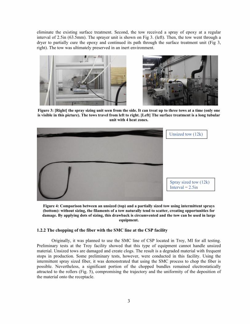
eliminate the existing surface treatment. Second, the tow received a spray of epoxy at a regular interval of 2.5in (63.5mm). The sprayer unit is shown on Fig 3. (left). Then, the tow went through a dryer to partially cure the epoxy and continued its path through the surface treatment unit (Fig 3, right). The tow was ultimately preserved in an inert environment.
Figure 3: [Right] the spray sizing unit seen from the side. It can treat up to three tows at a time (only one is visible in this picture). The tows travel from left to right. [Left] The surface treatment is a long tubular
unit with 4 heat zones.
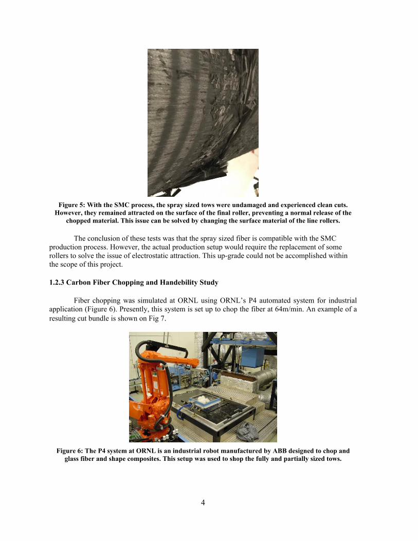
Figure 4: Comparison between an unsized (top) and a partially sized tow using intermittent sprays (bottom): without sizing, the filaments of a tow naturally tend to scatter, creating opportunities for damage. By applying dots of sizing, this drawback is circumvented and the tow can be used in large
equipment.
1.2.2 The chopping of the fiber with the SMC line at the CSP facility
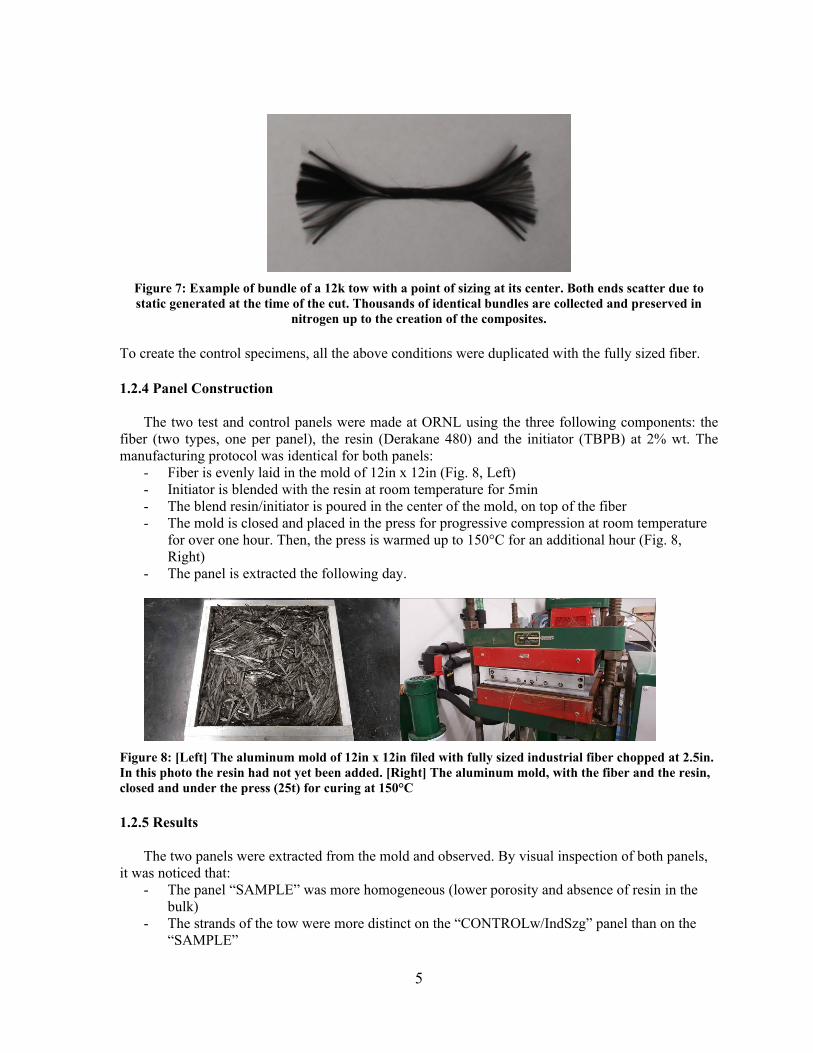
Originally, it was planned to use the SMC line of CSP located in Troy, MI for all testing. Preliminary tests at the Troy facility showed that this type of equipment cannot handle unsized material. Unsized tows are damaged and create clogs. The result is a degraded material with frequent stops in production. Some preliminary tests, however, were conducted in this facility. Using the intermittent spray sized fiber, it was demonstrated that using the SMC process to chop the fiber is possible. Nevertheless, a significant portion of the chopped bundles remained electrostatically attracted to the rollers (Fig. 5), compromising the trajectory and the uniformity of the deposition of the material onto the receptacle.
Unsized tow (12k)
Spray sized tow (12k)Interval = 2.5in
4
Figure 5: With the SMC process, the spray sized tows were undamaged and experienced clean cuts. However, they remained attracted on the surface of the final roller, preventing a normal release of the
chopped material. This issue can be solved by changing the surface material of the line rollers.
The conclusion of these tests was that the spray sized fiber is compatible with the SMC production process. However, the actual production setup would require the replacement of some rollers to solve the issue of electrostatic attraction. This up-grade could not be accomplished within the scope of this project.
1.2.3 Carbon Fiber Chopping and Handebility Study
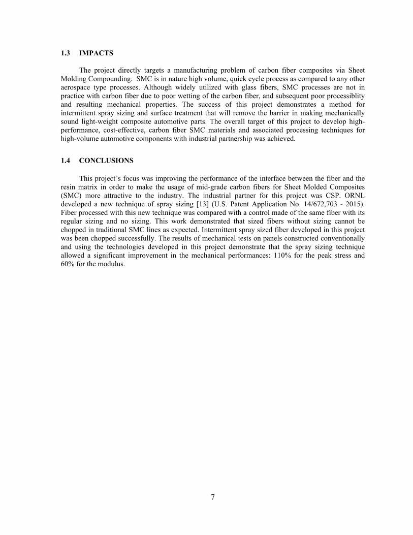
Fiber chopping was simulated at ORNL using ORNL’s P4 automated system for industrial application (Figure 6). Presently, this system is set up to chop the fiber at 64m/min. An example of a resulting cut bundle is shown on Fig 7.
Figure 6: The P4 system at ORNL is an industrial robot manufactured by ABB designed to chop and glass fiber and shape composites. This setup was used to shop the fully and partially sized tows.
5
Figure 7: Example of bundle of a 12k tow with a point of sizing at its center. Both ends scatter due to static generated at the time of the cut. Thousands of identical bundles are collected and preserved in
nitrogen up to the creation of the composites.
To create the control specimens, all the above conditions were duplicated with the fully sized fiber.
1.2.4 Panel Construction
The two test and control panels were made at ORNL using the three following components: the fiber (two types, one per panel), the resin (Derakane 480) and the initiator (TBPB) at 2% wt. The manufacturing protocol was identical for both panels:
- Fiber is evenly laid in the mold of 12in x 12in (Fig. 8, Left)- Initiator is blended with the resin at room temperature for 5min- The blend resin/initiator is poured in the center of the mold, on top of the fiber- The mold is closed and placed in the press for progressive compression at room temperature
for over one hour. Then, the press is warmed up to 150°C for an additional hour (Fig. 8, Right)
- The panel is extracted the following day.
Figure 8: [Left] The aluminum mold of 12in x 12in filed with fully sized industrial fiber chopped at 2.5in. In this photo the resin had not yet been added. [Right] The aluminum mold, with the fiber and the resin, closed and under the press (25t) for curing at 150°C
1.2.5 Results
The two panels were extracted from the mold and observed. By visual inspection of both panels, it was noticed that:
- The panel “SAMPLE” was more homogeneous (lower porosity and absence of resin in the bulk)
- The strands of the tow were more distinct on the “CONTROLw/IndSzg” panel than on the “SAMPLE”

6
These two observations indicate that the fiber in the panel “SAMPLE” has a better wet-through property compared to the fiber used in the panel “CONTROLw/IndSzg” (Figure ).
The two panels were cut into specimens and were tested using the recommendation of ASTM 790-92. The best part of each panel was selected to be cut. For each panel, twelve specimens were tested (Figs. 9 and 10). Results are shown in Table 1.
The mechanical results confirm the visual inspection: the panel “SAMPLE” shows a peak stress about twice as high as the values reported for the panel “CONTROLw/IndSzg”. In addition, the modulus increased by 60% (Table 1). This significant improvement in mechanical properties is a consequence of the fiber surface and is evidence of the efficacy of the spray sizing approach.
Figure 9: Both pictures show the same specimens, one from each panel, from front and side view (after mechanical tests). On the top, the “CONTROLw/IndSzg” specimen shows clearer tow strands from the
front view (left) and more pores from the side view (right) than the specimen from the panel “SAMPLE”, shown in the bottom position on both pictures.
Figure 10: The panels were cut into specimens and tested according to the recommendation of ASTM 790-92.
Table 1: Mechanical test resultsSAMPLE CONTROL w/Sizing
Peak stress (ksi)
Modulus (Mpsi)
Peak stress (ksi)
Modulus (Mpsi)
Mean 44.59 4.87 21.15 3.01Std. Dev 15.38 2.04 10.98 1.65
7
1.3 IMPACTS
The project directly targets a manufacturing problem of carbon fiber composites via Sheet Molding Compounding. SMC is in nature high volume, quick cycle process as compared to any other aerospace type processes. Although widely utilized with glass fibers, SMC processes are not in practice with carbon fiber due to poor wetting of the carbon fiber, and subsequent poor processiblity and resulting mechanical properties. The success of this project demonstrates a method for intermittent spray sizing and surface treatment that will remove the barrier in making mechanically sound light-weight composite automotive parts. The overall target of this project to develop high-performance, cost-effective, carbon fiber SMC materials and associated processing techniques for high-volume automotive components with industrial partnership was achieved.
1.4 CONCLUSIONS
This project’s focus was improving the performance of the interface between the fiber and the resin matrix in order to make the usage of mid-grade carbon fibers for Sheet Molded Composites (SMC) more attractive to the industry. The industrial partner for this project was CSP. ORNL developed a new technique of spray sizing [13] (U.S. Patent Application No. 14/672,703 - 2015). Fiber processed with this new technique was compared with a control made of the same fiber with its regular sizing and no sizing. This work demonstrated that sized fibers without sizing cannot be chopped in traditional SMC lines as expected. Intermittent spray sized fiber developed in this project was been chopped successfully. The results of mechanical tests on panels constructed conventionally and using the technologies developed in this project demonstrate that the spray sizing technique allowed a significant improvement in the mechanical performances: 110% for the peak stress and 60% for the modulus.

8
2. PARTNER BACKGROUND
Continental Structural Plastics (CSP) is a leading manufacturer and molder of composite materials. It is the largest compounder and molder of SMC (Sheet Molding Composite) and LFT-D (Direct Long Fiber Thermoplastic) in North America, their primary focus being on the automotive/transportation and industrial sectors. Their main product lines are Class A exterior body panels, molded structural components (thermoset and thermoplastic), and pick-up boxes.
CSP has operated since 1969. It currently employs 3,200 people in seven plants across North America. CSP works with large automotive companies such as Ford, GM, Chrysler, and Toyota. Its annual sales are currently in excess of $400 million
References:1. S. Ozcan, P. Filip, Wear of carbon fiber reinforced carbon matrix composites: Study of abrasive, oxidative wear and
influence of humidity, Carbon, 62: 240-247 (2013)2. A. Morris, M. Weisenberger, M. Abdallah, F. Vautard, H. Grappe, FL. Paulauskas, C. Eberle, D. Jackson, S. Mecham, AK.
Naskar, S. Ozcan, High Performance Carbon Fibers from Very High Molecular Weight Polyacrylonitrile Precursors, Carbon, 101: 245–252 (2016)
3. F. Vautard, H. Grappe, S. Ozcan, Engineered Interface Chemistry to Improve the Strength of Carbon Fiber Composites cured by electron beam. ACS Ind & Engr Chem Res. 53:12729-36 (2014)
4. F. Vautard, S. Ozcan, F. Paulauskas, J. Spruiell, H. Meyer, M Lance, “Influence of the carbon fiber surface microstructure on the surface chemistry generated by a thermo-chemical surface treatment” Applied Surface Science, 261: 473-480 (2012)
5. F. Vautard, S. Ozcan, H. Meyer, “Properties of thermo-chemically surface treated carbon fibers and of their epoxy and vinyl ester composites” Composite Part A, 43: 1120-1133 (2012)
6. F. Vautard, H. Grappe, S. Ozcan, Engineered Interface Chemistry to Improve the Strength of Carbon Fiber Composites cured by electron beam. ACS Ind & Engr Chem Res. 53:12729-36 (2014)
7. Y. Lu, MC. Cueva, E. Lara-Curzio, S. Ozcan, Improved mechanical properties of polylactide nanocomposites-reinforced with cellulose nanofibrils through interfacial engineering via amine-functionalization, Carbohydrate Polymers 131: 208-17 (2015)
8. Y. Lu, H. L. Tekinalp, C. Eberle, W. Peter, A. K. Naskar, S. Ozcan, Nanocellulose in Polymer Composites and Biomedical: Research and Applications, Tappi Journal, 13-6: 47-54 (2014)
9. F. Vautard, P. Grappe, S. Ozcan, Stability of carbon fiber surface functionality at elevated temperatures and its influence on interfacial adhesion, Applied Surface Science, 268: 61-72 (2013)
10. F. Vautard, S. Ozcan, FL. Paulasukas, "Method of improving adhesion of carbon fibers with a polymeric matrix". U.S. Patent No. 9,365,685 (2016)
11. F. Vautard, S. Ozcan, "Multifunctional curing agents and their use in improving strength of composites containing carbon fibers embedded in a polymeric matrix", U.S. Patent No. 9,617,398 (2017)
12. FL Paulasukas, S. Ozcan, A. Naskar, “Apparatus and process for surface treatment of carbon fibers”, U.S. Patent No. 9,340,677 (2016)
13. S.Ozcan, FL. Paulauskas, "Carbon Fiber Reinforcements for Sheet Molding Composites", U.S. Patent Application No. 14/672,703 (2015)