Composing architectures based on architectural patterns for … · 2018-03-21 · Composing...
32
Composing architectures based on architectural patterns for problem frames Christine Choppy 1 , Denis Hatebur 2,3 , and Maritta Heisel 2 1 LIPN, Institut Galil´ ee - Universit´ e Paris XIII, France, email: [email protected] 2 Universit¨ at Duisburg-Essen, Fachbereich Ingenieurwissenschaften, Institut f¨ ur Medientechnik und Software-Engineering, Germany, email: [email protected] 3 Institut f ¨ ur technische Systeme GmbH, Germany, email: [email protected] Abstract. The use of patterns is a promising way of developing high-quality software in a systematic way. Patterns can be used in different phases of the soft- ware lifecycle. Problem frames are patterns for representing simple software de- velopment problems, and architectural patterns are patterns for representing the coarse-grained structure of a piece of software. In a recent paper, we have defined architectural patterns corresponding to Jackson’s problem frames. To make use of problem frames, complex problems have to be decomposed into simple ones. The corresponding architectural patterns then provide solution struc- tures for these simple problems. Now the question arises how to combine the so- lutions structures of the simple subproblems to obtain a solution structure for the complex problem. The present paper addresses this question. Different subproblems of a complex problem can be related in various ways. They can be independent of each other, they can exclude each other, or they may have to be solved in a specific order. Such information can be used to combine the so- lutions structures of the subproblem to a solution structure of the overall problem. In this paper, we present a pattern-based software development process using problem frames and the corresponding architectural patterns. In decomposing a complex problem into simple subproblems, the relationships between the sub- problems are recorded explicitly. Based on this information, we give guidelines how to derive the software architecture for the overall problem from the software architectures of the simple subproblems. 1 Introduction Pattern-orientation is a promising approach to software development. Patterns provide structuring concepts that are of invaluable help for problem understanding and system design, and are a means to reuse software development knowledge on different levels of abstraction. They classify sets of software development problems or solutions that share the same structure. Patterns were introduced on the level of detailed object oriented design [10], and are now defined for different activities. Problem Frames [13] are patterns that classify software development problems. Architectural styles (or “architectural patterns”) are patterns that characterize software architectures [19]. Patterns for further development
Transcript of Composing architectures based on architectural patterns for … · 2018-03-21 · Composing...

Composing architectures based on architecturalpatterns for problem frames
Christine Choppy1, Denis Hatebur2,3, and Maritta Heisel2
1 LIPN, Institut Galilee - Universite Paris XIII, France, email:[email protected]
2 Universitat Duisburg-Essen, Fachbereich Ingenieurwissenschaften, Institut fur Medientechnikund Software-Engineering, Germany, email: [email protected]
3 Institut fur technische Systeme GmbH, Germany, email: [email protected]
Abstract. The use of patterns is a promising way of developing high-qualitysoftware in a systematic way. Patterns can be used in different phases of the soft-ware lifecycle. Problem frames are patterns for representing simple software de-velopment problems, and architectural patterns are patterns for representing thecoarse-grained structure of a piece of software. In a recent paper, we have definedarchitectural patterns corresponding to Jackson’s problem frames.To make use of problem frames, complex problems have to be decomposed intosimple ones. The corresponding architectural patterns then provide solution struc-tures for these simple problems. Now the question arises how to combine the so-lutions structures of the simple subproblems to obtain a solution structure for thecomplex problem. The present paper addresses this question.Different subproblems of a complex problem can be related in various ways. Theycan be independent of each other, they can exclude each other, or they may haveto be solved in a specific order. Such information can be used to combine the so-lutions structures of the subproblem to a solution structure of the overall problem.In this paper, we present a pattern-based software development process usingproblem frames and the corresponding architectural patterns. In decomposing acomplex problem into simple subproblems, the relationships between the sub-problems are recorded explicitly. Based on this information, we give guidelineshow to derive the software architecture for the overall problem from the softwarearchitectures of the simple subproblems.
1 Introduction
Pattern-orientation is a promising approach to software development. Patterns providestructuring concepts that are of invaluable help for problem understanding and systemdesign, and are a means to reuse software development knowledge on different levelsof abstraction. They classify sets of software development problems or solutions thatshare the same structure.
Patterns were introduced on the level of detailed object oriented design [10], andare now defined for different activities.Problem Frames[13] are patterns that classifysoftware developmentproblems. Architectural styles(or “architectural patterns”) arepatterns that characterize software architectures [19]. Patterns for further development

phases includedesign patterns, frameworks, andidiomsor “code patterns”. Using pat-terns, we can hope to construct software in a systematic way, making use of a body ofaccumulated knowledge, rather than starting from scratch.
It is acknowledged that the first steps of software development are essential to reachthe best possible match between the expressed requirements and the proposed softwareproduct, and to eliminate any source of error as early as possible. Therefore, we proposeto use patterns starting from the requirements elicitation phase of the software develop-ment life-cycle, as advocated by Fowler [9] or Sutcliffe et al. [20, 21]. M. Jackson [13]proposes the concept ofproblem framesfor presenting, classifying and understandingsoftware development problems. A problem frame is a characterization of a class ofproblems in terms of their main components and the connections between these com-ponents. Once a problem is successfully fitted to a problem frame, its most importantcharacteristics are known.
Gaining a thorough understanding of the problem to be solved is a necessary pre-requisite for solving it. However, when using problem frames, one can even hope formore than just a full comprehension of the problem at hand. Since problem frames arepatterns, they represent problem structures that occur repeatedly in practice. Hence, it isworthwhile to look for solution structures that match the problem structures representedby problem frames.
The construction of the solution of a software development problem should beginwith the decision on the main structure of the solution, i.e., a decision on the softwarearchitecture. We exploit the knowledge gained in representing a problem as an instanceof a problem frame in taking that decision. In [5], we define architectural patterns cor-responding to Jackson’s problem frames, taking into account the characteristics of theproblems fitting to the given problem frame. The structure provided by an architecturalpattern constitutes a concrete starting point for the process of constructing a solution toa problem that is represented as an instance of a problem frame.
Different subproblems of a complex problem can be related in various ways. Theycan be related sequentially, by alternative or they can be independent (parallel). Suchinformation can be used to combine the solutions structures of the subproblem to asolution structure of the overall problem.
In this paper, we present a pattern-based software development process using prob-lem frames and the corresponding architectural patterns. In decomposing a complexproblem into simple subproblems, the relationships between the subproblems are recor-ded explicitly. Based on this information, we give guidelines on how to derive thesoftware architecture for the overall problem from the software architectures and thecomponent specifications of the simple subproblems.
Throughout this work, we use object-oriented notations, mostly from UML 2.0 [23].Although our pattern-based software development process does not strictly depend onobject-orientation, it works particularly well in an object-oriented setting.
The rest of the paper is organized as follows: after introducing the basic conceptsof our work in Section 2, we briefly introduce the architectural patterns we developedfor the various problem frames in Section 3. Then, we discuss related work in Section4. Our pattern-based software development process is presented in Section 5 and illus-
2

trated by a case study in Section 6. In Section 7, we conclude with a discussion of ourapproach and directions for future research.
2 Basic Concepts
The patterns used in our development process are problem frames and architectural pat-terns. As a notation for our architectural patterns, we use composite structure diagramsof UML 2.0. In the following, we give brief descriptions of these three ingredients ofour work.1
2.1 Problem Frames
Jackson [13] describes problem frames as follows:
“A problem frame is a kind of pattern. It defines an intuitively identifiable prob-lem class in terms of its context and the characteristics of its domains, interfacesand requirement.”
Solving a problem is accomplished by constructing a “machine” and integrating itinto the environment whose behavior is to be enhanced.
For each problem frame a diagram is set up (see left-hand side of Fig. 1). Plain rect-angles denote application domains (that already exist), rectangles with a double verticalstripe denote the machine domains to be developed, and requirements are denoted witha dashed oval. They are linked together by lines that represent interfaces, also calledshared phenomena.
The following problems fit to theRequired Behaviourproblem frame:
‘There is some part of the physical world whose behaviour is to be controlledso that it satisfies certain conditions. The problem is to build a machine thatwill impose that control.’
The corresponding frame diagram is shown on the left-hand side of Figure 1. The “C” inthe frame diagram indicates that theControlled domainmust be causal. The machine isalways a causal domain (so an explicit “C” is not needed). The notation “CM!C1” meansthat the causal phenomenaC1 are controlled by the Control machineCM. The dashedline represents a requirements reference, and the arrow shows that it is aconstrainingreference.
This problem frame is appropriate forembedded systems, where the machine to bedeveloped is embedded in a physical environment that must be controlled. The commu-nication between the machine and the physical environment takes place viasensorsandactuators. Thus, only by virtue of sensors and actuators can there be shared phenom-ena between the machine and its environment. Sensors realize the phenomenaC2 ofthe frame diagram, i.e., the phenomena controlled by the environment but observable
1 In the following, we will also use sequence diagrams and state machines. However, these no-tations are well-known and intuitive, and we will not explain them here.
3

ControlCD!C2
CM!C1
domainControlled
C
C3
machine behaviourRequired
Controlled ControlledDomain (C2) Domain (C1)
C2’
C2’’
C1’
C1’’
Application
Sensor IAL
Sensor HAL
Actuator IAL
Actuator HAL
Control Machine
Fig. 1.Required Behaviour Frame Diagram and Architecture
by the machine. Actuators realize the phenomenaC1 of the frame diagram, i.e., thephenomena controlled by the machine and observable by the environment.
For example, we might want to build a machine that keeps the temperature of someliquid between given bounds. Then, the temperature of the liquid would be a sharedphenomenon controlled by the environment. The corresponding sensor would be a ther-mometer. Another shared phenomenon would be the state of a burner. That state wouldbe controlled by the machine, i.e., the machine is able to switch the burner on or off.
Jackson defines five basic problem frames, namelyRequired Behaviour, CommandedBehaviour, Information Display, WorkpiecesandTransformation. In order to use a prob-lem frame, one must instantiate it, i.e., provide instances for its domains, interfaces andrequirements.
2.2 Architectural Styles
According to Bass, Clements, and Kazman [2],
“the software architecture of a program or computing system is the structure orstructures of the system, which comprise software components, the externallyvisible properties of those components, and the relationships among them.”
Architectural styles are patterns for software architectures. A style is characterizedby [2] (i) a set of component types (e.g., data repository, process, procedure) that per-form some function at runtime, (ii) a topological layout of these components indicatingtheir runtime interrelationships, (iii) a set of semantic constraints (for example, a datarepository is not allowed to change the values stored in it), and (iv) a set of connec-tors (e.g., subroutine call, remote procedure call, data streams, sockets) that mediatecommunication, coordination, or cooperation among components.
When choosing an architecture for a system, usually several architectural stylesare possible, which means that all of them could be used to implement the functionalrequirements. We use UML 2.0 composite structure diagrams (see Section 2.3) to rep-resent architectural patterns as well as concrete architectures.
4
2.3 Composite Structure Diagrams
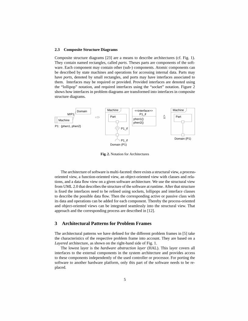
Composite structure diagrams [23] are a means to describe architectures (cf. Fig. 1).They contain named rectangles, calledparts. Theses parts are components of the soft-ware. Each component may contain other (sub-) components. Atomic components canbe described by state machines and operations for accessing internal data. Parts mayhaveports, denoted by small rectangles, and ports may have interfaces associated tothem. Interfaces may be required or provided. Provided interfaces are denoted usingthe “lollipop” notation, and required interfaces using the “socket” notation. Figure 2shows how interfaces in problem diagrams are transformed into interfaces in compositestructure diagrams.
P1: {phen1, phen2}
Machine
DomainM!P1
Machine
Part
Domain (P1)
<<interface>>P1_if
phen1()phen2()
Machine
Part
P1_if
=
Domain (P1)P1_if
Fig. 2.Notation for Architectures
The architecture of software is multi-faceted: there exists a structural view, a process-oriented view, a function-oriented view, an object-oriented view with classes and rela-tions, and a data flow view on a given software architecture. We use the structural viewfrom UML 2.0 that describes the structure of the software at runtime. After that structureis fixed the interfaces need to be refined using sockets, lollipops and interface classesto describe the possible data flow. Then the corresponding active or passive class withits data and operations can be added for each component. Thereby the process-orientedand object-oriented views can be integrated seamlessly into the structural view. Thatapproach and the corresponding process are described in [12].
3 Architectural Patterns for Problem Frames
The architectural patterns we have defined for the different problem frames in [5] takethe characteristics of the respective problem frame into account. They are based on aLayeredarchitecture, as shown on the right-hand side of Fig. 1.
The lowest layer is thehardware abstraction layer(HAL). This layer covers allinterfaces to the external components in the system architecture and provides accessto these components independently of the used controller or processor. For porting thesoftware to another hardware platform, only this part of the software needs to be re-placed.
5

The hardware abstraction layer is used by theinterface abstraction layer(IAL).This layer provides an abstraction of the (low-level) values yielded by the sensors andactuators. For example, a frequency of wheel pulses could be transformed into a speedvalue. Thus, in the interface abstraction layer, values for the monitored and controlledvariables (see [17]) of the system are computed. It is possible that these variables haveto be computed from the values of several hardware interfaces. For safety-critical soft-ware components, the interface abstraction layer will usually make use of redundantarrangements of sensors and actuators.
The highest layer of the architecture is theApplicationlayer. This layer only has todeal with variables from the problem diagram. Therefore, the system requirements canbe directly mapped to the software requirements of the application layer, as describedby Bharadwaj and Heitmeyer [3].
Note that the phenomenaC3 do not occur in the architecture2, because they do notbelong to the interface of the machine domain.
Thus, the architecture shown on the right-hand side of Fig. 1 represents an adequatestructure for theControl machine of the left-hand side of Fig. 1. The interfaces ofthe architectural patterns correspond exactly to the interfaces of the machine domainsas defined in the different frame diagrams. Hence, the architecture refines exactly themachine to build; it neither adds nor leaves out any shared phenomena as compared tothe problem description.
Of course, our architectural patterns are not the only possible way to structure themachine domain solving the problem that fits to a given problem frame. However, thekind of (layered) architecture we propose has proven useful in practice (see for example[4, 12, 22]), and allows for combining solutions to different subproblems of complexproblems in a systematic way. It is also flexible enough to be combined with otherarchitectural styles. We have validated this kind of architecture in several industrialprojects, dealing for example with smart cards, protocol converters, web/mail-servers,and real-time operating systems.
4 Related Work
A number of research activities deal with the use of patterns in the software develop-ment process. We consider here mainly those related with the use of problem frames,also in relationship with architectural styles.
Aiming to integrate problem frames in a formal development process, Choppy andReggio [8] show how a formal specification skeleton may be associated with some prob-lem frames. Choppy and Heisel show in [6, 7] that this idea is independent of concretespecification languages. In that work, they also give heuristics for the transition fromproblem frames to architectural styles. In [6], they give criteria for (i) helping to selectan appropriate basic problem frame, and (ii) choosing between architectural styles thatcould be associated with a given problem frame.
2 In the following, we use the word “architecture” instead of “architectural pattern” for reasonsof readability. It is clear, however, that the components shown in the architectural diagramshave to be instantiated in order to obtain a concrete software architecture.
6

In [7], a proposal for the development of information systems is given using updateor query problem frames. A component-based architecture reflecting the repository ar-chitectural style is used for the design and integration of the different system parts.
The approach developed by Hall, Rapanotti et al. [11, 18] is quite complementary toours, since the idea developed there is to introduce architectural concepts into problemframes (introducing “AFrames”) so as to benefit from existing architectures. In [11], theapplicability of problem frames is extended to include domains with existing architec-tural support, and to allow both for an annotated machine domain, and for annotationsto discharge the frame concern. In [18], “AFrames” are presented corresponding to thearchitectural styles Pipe-and-Filter and Model-View-Controller (MVC), and applied totransformation and control problems.
Let us also mention Lavazza and Del Bianco [15] who do not use architectures, butprovide a description of commanded and required behavior problem frames in UML-RT, focusing on active objects or “capsules” communicating through ports (defined byprotocols). Moreover, they provide a real time version of OCL, called OTL.
Barroca et al. [1] extend the problem frame approach withcoordinationconcepts.This leads to a description ofcoordination interfacesin terms ofservicesandevents(referred to respectively here as actuators and sensors) together with required properties,and the use ofcoordination rulesto describe the machine behavior.
5 Software Development Process
In the following, we describe a pattern-based software development process. That pro-cess is based on problem frames [13] and the corresponding architectural patterns thatwe propose in [5]. We mostly use concrete object-oriented notations (often taken fromUML [23]) to express the results of the different steps of the process. In principle, theprocess could be carried out using other notations, but the procedures we give below onhow to execute the steps would have to be adjusted in that case.
The novelty of the process is that the relationships between the subproblems areexpressed explicitly, and that these relationships are exploited when generating a globalsoftware architecture for the overall problem. Although Jackson [13] gives some hintson how to decompose problems into subproblems, there is no general procedure forconstructing the solution of the overall problem from the solutions of the subproblems.The current paper proposes an approach on how to achieve that composition.
Our pattern-based software development process using problem frames and archi-tectural patterns proceeds as follows: first, a context diagram showing the problem con-text is set up (for an example, see Figure 3). Then, the overall problem is decomposedinto subproblems that should fit to existing problem frames. This decomposition canbe achieved in various ways, for example by use-case decomposition, or by projection,as proposed by Jackson [13]. The decomposition results in a set of problem diagrams(that should be instantiated frame diagrams whenever possible) and the informationhow the different subproblems are related, expressed e.g. as a grammar. For each sub-problem, a specification for the machine domain must be derived, thus addressing theframe concern. Each machine domain corresponding to a subproblem is then structuredby instantiating the architectural patterns we have proposed in [5]. The instantiated pat-
7

terns must afterwards be merged to obtain the architecture of the machine solving theoverall problem. It ts the main contribution of the present paper to show how that com-position can be performed in a systematic way, making use of the relations betweenthe subproblems that were expressed during problem decomposition. Finally, the com-ponents of the combined architecture must be specified in more detail, and it must beshown that the combined architecture fulfils the specifications of all subproblems.
The process consists of twelve steps that we explain one by one. The steps that arethe most important for the task of constructing the overall solution structure from thesubproblem solution structures are Steps 3, 9, and 10.
1. Collect requirements and domain knowledge.Input An informal description of the task.Procedure The requirements (optative statements) have to be expressed, as well
as knowledge about the environment in which the machine (i.e. the softwaresystem to be developed) has to operate (indicative statements). Whereas therequirements have to be achieved by constructing the machine, the domainknowledge expresses facts that are true no matter how the machine is built.(For a more details, see [24].)
Output A set R of requirements, and a setD of domain knowledge statements.These can be expressed in natural language, or in semi-formal or formal nota-tions.
Validation The statements contained inR andD must be non-contradictory.2. Draw a context diagram.
Input An informal description of the task.Procedure We must identify all domains that are relevant to the problem at hand,
and the phenomena that are shared by different domains.Output A context diagram containing all relevant domains and shared phenomena.
(For a more details, see [13].)Validation The results of Steps 1 and 2 must be consistent, i.e., all domains and
phenomena mentioned inR andD must be contained in the context diagram,and all domains and phenomena of the context diagram must be related to someelement ofR or D.
3. Decompose the problem into simple subproblems, and express the relations be-tween the different subproblems. If possible, the subproblems should fit to knownproblem frames (or variants).
Input Results of Steps 1 and 2.Procedure There are different possibilities to decompose a complex problem into
subproblems. Jackson [13] proposes a parallel decomposition using projection,but a decomposition by use-cases (for an example, see [7]) or a top-down de-composition are also possible. Subproblems refer to related sets of require-ments, and they should only constrain a single domain (otherwise, the sub-problem is not simple but needs further decomposition).The following relationships between subproblems are possible:parallel sub-problems are largely independent of one another, and the composed machinewill have to treat the problems in parallel.Sequentialsubproblems have to be
8

treated one after the other.Alternativeproblems are exclusive. Only one ofthem will have to be treated at a given time.However, composing the solution of the overall problem from the solutions ofthe subproblems doesnot mean to develop an independent program for eachsubproblem and then compose these programs. Instead, the solutions to thesubproblems will contain common components that have to be identified andthen merged accordingly (cf. Steps 9 and 10). This is the challenge of the com-position problem.
Output A set of problem diagrams, being mostly instantiated frame diagrams,and an expression of the subproblem relationships. To express subproblem re-lationships, different means of expression are appropriate, for example pro-cess algebra-like notations, grammars, high-level sequence charts, or sequencecharts using combined fragments (the latter two introduced in UML 2.0).
Validation All requirements have to be captured, and each requirement must beassigned exactly to one subproblem, otherwise the requirement must be split.The problem diagrams must be consistent with the context diagram of Step 2.The following operations preserve consistency:
– leave out domains (with corresponding interfaces)– combine several domains into one domain– divide one domain– reduce an interface between domains– refine phenomena– combine (i.e., abstract) phenomena
4. Derive a specification for each subproblem.Input Results of Steps 1–3.Procedure Whereas requirements describe how the environment should behave
once the machine is integrated in it, the specification describes the machine andforms the basis for its construction. Specifications are implementable require-ments, and they are derived from the requirements using domain knowledge.For more details, see [14].
Output A specification for each subproblem, expressed as a set of sequence dia-grams. State invariants should be annotated for the domains in the environmentof the machine.
Validation Specification and domain knowledge must be non-contradictory. Thespecification, together with the domain knowledge, must imply that the require-ments are fulfilled. In performing that proof, the frame concern is addressed.The frame concern provides a structure for the correctness proof.Additionally, the phenomena of the machine domain must be consistent withthe signals in the sequence diagrams, i.e., they must have the same name, or amapping must be created. All phenomena at the interfaces of the machine mustbe used in at least one sequence diagram. The annotated state invariants mustallow to combine the sequence diagrams in the same way as the relationshipsof Step 3 describe.
5. Define an architecture for each subproblem.Input Problem diagrams resulting from Step 3.
9

Procedure If a subproblem fits to a known problem frame, then a simple instanti-ation of the pattern we gave in [5] will suffice. If a subproblem is not an exactinstance of a problem frame but a variant, then modifications of our architec-tural patterns will be necessary. If a subproblem is unrelated to any problemframe, then an appropriate architecture has to be developed from scratch.
Output A subproblem architecture for each subproblem, expressed as a compositestructure diagram.
Validation If the architectural diagrams are instantiations of the given patterns, novalidation is necessary. Otherwise, it must be checked that all domains of theproblem diagram are captured in the architecture and that the external inter-face of the architecture coincides with the machine interface of the problemdiagram.
6. Specify the interface classes for all interfaces of all subproblem architectures.Input Results of Steps 3 and 5.Procedure For each interface contained in a subproblem architecture, the corre-
sponding operations or signals, respectively, have to be defined, and providedand required interfaces must be distinguished.
Output A set of interface classes.Validation All interfaces must be covered. The signals or operations in the in-
terfaces classes must be the same as the signals in the sequence diagrams ofStep 4.
7. Specify all components of all subproblem architectures.Input Results of Steps 4–6.Procedure For each component, its external behavior is expressed using sequence
diagrams. For the application layer (cf. Fig. 1), it should be possible to re-usethe specifications developed in Step 4. To reuse the specifications, the interfacephenomena have to be adjusted according to the functionality of the IAL andthe HAL. Moreover, to prepare for the next step, the sequence diagrams shouldbe annotated with state invariants, as in Step 4.
Output A set of sequence diagrams, annotated with state information.Validation All components must be covered. The signals in specification must be
defined in the interfaces classes. The sequence diagrams for the componentstogether must describe the same behavior as described in Step 4.
8. Define a state machine and the used data for each architectural component.Input Result of Step 7.Procedure Use the state information contained in the sequence diagrams to con-
struct a state machine specifying the behavior of each architectural component.This step may seem redundant, because we have already developed a specifi-cation for each component using sequence diagrams. However, the sequencediagrams only show specific scenarios and are possibly incomplete. A statemachine and the used data specify the overall behavior of the component inquestion and will later serve as the basis for the specification of the composedarchitecture and for the implementation. An approach to construct state ma-chines from sequence diagram is described in [16]. The sequence diagrams, onthe other hand, can be used for testing.The local data for each component can be defined using class diagrams.
10

Output A set of state machines and class diagrams.Validation Each architectural component is covered, and each state machine is
complete, i.e., each possible input signal (as specified in Step 6) is taken intoaccount. Each state machine must behave as described in its correspondingsequence diagrams.Moreover, all referenced interface classes must be the same as the interfaceclasses of the subproblem architecture of the respective component (Step 6).
9. Develop the global architecture of the machine to be developed by combination ofthe subproblem architectures.Input Relationships between subproblems as specified in Step 3, results of Steps
5 and 6.Procedure The crucial point of this step is to decide if two components contained
in different subproblem architectures should occur only once in the global ar-chitecture, i.e., they should be merged. To decide this question, we make useof the information gathered when decomposing the overall problem into sub-problems. We distinguish the following cases, where all cases but the first oneconcern application components:(a) The components are hardware (HAL) or interface abstraction layers (IAL),
establishing the connection to some hardware device.Such components should be merged if and only if they are associated tothe same hardware device.
(b) Two application components belong to subproblems being related sequen-tially or by alternative.Such components should be merged into one application component.
(c) Two application components belong to parallel subproblems and sharesome output phenomena.Such components should be merged, because the output must be generatedin a way satisfying both subproblems.
(d) Two application components belong to parallel subproblems and sharesome input phenomena.If the components do not share any output phenomena, both alternatives(merging the components, or keeping them separate) are possible. If thecomponents are not merged, then the common input must be duplicated.
(e) Two application components belong to parallel subproblems and do notshare any interface phenomena.Such components should be kept separately.
Output A composite structure diagram for the global architecture, i.e. the architec-ture of the machine solving the original problem, and a set of interface classesfor the global architecture.
Validation The global architecture must contain all components and interfaces ofall subproblem architectures. It must be possible to map all signals in the ex-ternal interfaces to the phenomena at the machine interfaces of the contextdiagram developed in Step 2.
10. Define state machines for all components of the global architecture that were mergedfrom components of different subproblem architectures by merging their respectivestate machines.
11

Input Results of Steps 8 and 9.Procedure According to the case distinction we made in Step 9, we proceed as
follows:– Case 9a. Often, the state machines will already be equal, because they de-
scribe the same device. If not, the state machines must be merged manually.In many cases, we only need to add the additional signals to the appropriatestates.
– Case 9b. The composition can be achieved by using composite states. Theconnecting arcs between the sub-automata depend on the problem.
– Case 9c. Here, the merge depends on the problem to be solved. Often, therewill be a priority between the different subproblems that has to be takeninto account when defining the common state machines. As a heuristic, wecan note that priorities between subproblems will be necessary when thetwo subproblems constrain the same domain.
– Case 9d. The merge has to be performed manually.Output A set of state machines.Validation Each composed state machine is complete and covers all input events
that can be sent by the components with an interface to the composed state ma-chine. All sequence diagrams of all subproblems for the component specifiedin Step 7 describe the same behavior as the corresponding state machine.
11. Specify operations and private data types.12. Implement and test the software system.
As the last two steps are beyond the scope of this paper, we do not describe themhere.
6 Case Study
We now illustrate the process by the case study of an automatic teller machine (ATM).
6.1 Requirements, Domain Knowledge – Step 1
The mission of an ATM is to provide customers with money, provided that they areentitled to withdraw the desired amount.
R1 To use the ATM a valid pin and a bank card is required.R2 The withdrawal should be refused when the request is bigger than the balance.R3 The card should be retracted if the customer does not take the ejected card.R4 The account is updated when the customer takes the money.R5 After the withdrawal was granted and the card ejected, the money should be taken
from the supply, put to the money case, and the case should be opened. After thecustomer took the money, the money case should close, otherwise the money shouldbe retracted.
R6 All input phenomena should be logged.R7 The logged input phenomena can be queried by the administrator.
An example of domain knowledge is that theMoney Casesendsbanknotes removedwhen theCustomertakes the banknotes.
12

Card reader
Accountdata
take_banknotes_from supplyput_banknote_to_case
retract_banknotes_from_caseopen_case, close_case
banknotes_removed
*
Admin
Case Money supply /
ATMaccount_balancewithdraw_money
Customer
insert_card, remove_cardretract_card, eject_card
ask_pin, granted_OKrefuse_withdrawalenter_requestenter_pin
take_banknotes
card_insideno_card_inside
insert_money
*request_logdisplay_log
Fig. 3.Context Diagram for ATM Problem
6.2 Context Diagram - Step 2
Figure 3 shows the structure of the ATM problem context, where several domains andthe corresponding shared phenomena are identified.
6.3 Subproblems - Step 3
The ATM consists of the subproblemsAuthenticate, Request, Update Account, TakeMoney, Take Card, Log, andDisplay Log. The following figures provide the problemframe instances for these subproblems.
Figure 4 shows the problem diagram forAuthenticate. It is an instantiation of thecommanded behavior frame with an additional feedback phenomenonAM!E6. Require-mentR1 can be assigned to this problem diagram.
Customer
Card reader
C!E5
Authen−ticationmachine
AM!C2CR!C1
C3
C!E4AM!E6
E4,E5,E6
Authentication
C1: {card inside}C2: {retract card}C3: {card control}
E4: {enter pin}E5: {insert card}E6: {ask pin}
Fig. 4.Problem Diagram for Authenticate (commanded behavior variant)
13

The problem diagram forRequest(shown in Figure 5) describes requirementR2.It is a variant of the commanded information frame. This variant is called informationdisplay and described in [7].
Requestmachine Display
Accountdata
AD!C7 C8
RM!E9 Y10
Customer E11C!E11
Requestmoney
C7: {account balance}C8: {account data}E9: {granted OK,
refuse withdrawal}
Y10: {withdrawal possible}E11: {enter request}
Fig. 5.Problem Diagram for Request (commanded information variant, information display)
Figure 6 shows the problem diagram forTake Card. It is an instantiation of therequired behavior frame. TheCustomeris additionally included to show all relevantactions in the environment. RequirementR3 can be assigned to this problem diagram.
Customer
Card reader
Takecardmachine
CR!C12TCM!C13 C14
C!E15
E15
Takecard
C12: {card inside}C13: {eject card, retract card}
C14: {eject, retract}E15: {take card}
Fig. 6.Problem Diagram for Take Card (required behavior)
Figure 7 shows the problem diagram forUpdate Account, which is a variant of theWorkpiecesframe. The requirementR4 is described with this problem frame.
The problem diagram forTake Money(Figure 8) is a variant of theRequired Be-haviour problem frame (Figure 1), where we added theCustomerand his/her connec-tion with theMoney Case. The requirementR5 is described with this problem frame.
14

Updateaccount
accountUpdate
machine
Customer
C!E18
Money Case
dataAccount
MC!C19
Y17
E18
UAM!Y16
Y16: {update account}Y17: {account data}
E18: {take banknotes}C19: {banknotes removed}
Fig. 7.Problem Diagram for Update Account (Workpieces variant)
Customer
Takemoneymachine
Money Supply /Case
MCC!C19TMM!C20 C21
E18
C!E18 Take money
E18: {take banknotes}C19: {banknotes removed}C20: {take banknotes from supply, put banknote to case, open case, close case, re-
tract banknotes from case}C21: {control money supply, control money case}
Fig. 8.Problem Diagram for Take Money (required behavior variant)
The problem diagram forLog (cf. requirementR6) is shown in Figure 9. The work-pieces problem frame is instantiated. The domainsCard reader, Money case, andCus-tomerin the problem diagram represents theUser in the problem frame.
The problem diagram forDisplay Log (shown in Figure 10) describes requirementR7. It is a variant of the commanded information frame. This variant is called informa-tion display and described in [7].
The dependencies between the subproblems can be summarized using a context-freegrammar describing the possible sequences. In the following grammar, “||” denotes par-allel problems and “|” denotes an alternative.
< start >::= (< idle > ||Log||DisplayLog)< idle >::= (Authenticate < authenticated > |Authenticate < idle >)< authenticated >::= (Request < granted > |Request < refused >)< granted >::= (TakeCard < granted no card > |TakeCard < idle >)< refused >::= TakeCardRefused < idle >
15

(Logs)
machineLog
Data storage Y23LM!Y23
Customer
Money caseCard reader,
C!E5,E15,E18C!E4,E11
CRMC!C1,C12, C19 Log inputphenomena
C22
E4,E11
Y22: {card reader money case input phenomena}E23: {log data}
C1, C12 . . . as given in the other figures
Fig. 9.Problem Diagram for Log (Workpieces)
Admin
Admin Displaylogdisplay
Display
machinelog
Datastorage(Log) Y25
E27
DS!Y24
A!E27
DLM!C26 C26
Y24: {log data}Y25: {logged input phenomena}C26: {log}E27: {request log}
Fig. 10.Problem Diagram for Display Log commanded information variant, information display)
16

< granted no card >::= (UpdateAccount||TakeMoney) < idle >
The last line means that, once the card is removed and withdrawal is granted, bothUpdateAccountand TakeMoneywill take place in parallel, and then the idle state isreached.
6.4 Specification – Step 4
For each problem diagram, the specification is expressed by sequence diagrams that aregiven in the following figures.
The sequence diagram for the subproblemAuthenticateis shown in Figure 11. Thisdiagram expresses that the card is retracted after 3 unsuccessful attempts. TheCustomeris authenticated if the valid PIN is entered.
The sequence diagram for the subproblemRequestis shown in Figure 12. When anauthenticated customer enters a request, his/her balance is checked and the access forthe customer is granted or refused.
Fig. 11.Sequence Diagram for Authenticate
Fig. 12.Sequence Diagram for Request
The sequence diagrams for the subproblemTake Cardare shown in Figures 13 and14. The sequence is different depending on the state of the customer. If the access isgranted, the ejected card might be retracted after a certain time period, or the customertakes the card and he/she can continue with the withdrawal process.
17

If the access is refused, the ejected card is retracted or the customer takes it. In bothcases the access is not granted, as shown in Fig. 14.
Fig. 13.1st Sequence Diagram for Take CardFig. 14.2nd Sequence Diagram for Take Card
The sequence diagram for the subproblemUpdate Accountis shown in Figure 15.The sequence diagram expresses that the account data are updated when the banknotesare removed.
The sequence diagram expresses the specificationS5 for the subproblemTake Moneyis shown in Figure 16. It also contains the domainCustomerto illustrate the interrelationbetween the requirement, the domain knowledge and the specification:
R5 ... After the customer took the money, theMoney Caseshould close, otherwise themoney should be retracted.
D1 TheMoney Casesendsbanknotes removed after theCustomertook the banknotes.S5 ... After the signalbanknotes removed occurs, theMoney Caseshould close, oth-
erwise the money should be retracted.
Therefore the implicationD1 ∧ S5 ⇒ R5 is fulfilled. This sequence occurs in parallelto to the sequence shown in Fig. 15. This is possible, because both diagrams start withthe same state invariantgrantedno card and only in Fig. 15 the state of the customerafter this sequence is constraint.
The sequence diagram for the subproblemLog is shown in Figure 17. It shows thatall input signals are logged in a data storage. This sequence is not constraint by a stateinvariant and is parallel to all other sequence diagrams.
The sequence diagram for the subproblemDisplay Logis shown in Figure 17. Itshows that the stored logs can be queried by the administrator. This sequence also is notconstraint by a state invariant and is parallel to all other sequence diagrams.
6.5 Instantiated Architectural Patterns – Step 5
For each problem diagram, an architectural pattern from [5] is instantiated.
18

Fig. 15.Sequence Diagram for Update Account
Fig. 16.Sequence Diagram for Take Money
Fig. 17.Sequence Diagram for Log
Fig. 18.Sequence Diagram for Display Log
The architecture for the subproblemAuthenticateis shown in Fig. 19. It consistsof an Authentication Application, a Card In IAL, a Card Out IAL, the correspondingHAL components, and aUser Interface. The architecture for the subproblemRequestis shown in Fig. 20. It consists of aRequest Application, a User Interfaceand aData
19

Card In IAL
Card In HALCard Out HAL
Card Out IAL
UserInterface
from Customer (E5)Card Reader (C2) Card Reader (C1)Customer (E4, E6)
E4’’ E6’’
C2’
C2’’
C1’
C1’’
Authentication Application
Fig. 19.Architecture for Authenticate
DataStorage(Account Data)
UserInterface
Request Application
E9’’, E11’’ C7
Customer (E9, E11)
Fig. 20.Architecture for Request
Storage. The architecture for the subproblemTake Card(see Fig. 21) consists of thehardware abstraction layer and the interface abstraction layer for the Card, and aTakeCard Application. The architecture for the subproblemsUpdate Accountis shown in
Card In IAL
Card In HALCard Out HAL
Card Out IAL
Card Reader (C13) Card Reader (C12) from Customer (E15)
Take Card Application
C13’
C13’’ C12’’
C12’
Fig. 21.Architecture for Take Card
DataStorage(Account Data)
Update Account Application
Money Se.HAL
Money Se.IAL
Case (C19)Sensor from
Customer (E18)
Money Supply/
C19’
C19’’Y16
Fig. 22.Architecture for Update Account
Fig. 22. The architecture for the subproblemsTake Moneyis shown in Fig. 23. Thearchitecture for the subproblemLog consists of aLog Applicationand all componentsthat handle input phenomena. It is shown in Fig.25. The architecture for the subproblemDisplay Logconsists of aDisplay Log Application, aUser Interfacefor the administra-tor, and aData Storagecontaining the logs. (see Fig. 24).
6.6 Interface Classes – Step 6
As we use very abstract phenomena for the case study, the IAL and the HAL are triv-ial, and we obtain their interface phenomena simply by renaming the external phe-nomena. Phenomena controlled by the machine become provided interfaces, and phe-nomena controlled by the environment become required interfaces of the complete ma-chine. A provided interface class is e.g.C19 (see Figs. 7 and 22) with the method
20

Money Se.HAL
Money Se.IAL Money Ac.IAL
Money Ac.HAL
Money Supply/
ActuatorCase (C19) Case (C20)Sensor from
Customer (E18)
Money Supply/
Take Money Application
C19’ C20’
C19’’ C20’’
Fig. 23.Architecture for Take Money
DataUserStorage(Logs)
Interface(Admin)
Admin (E27)Admin Display (C26)/
Display Log Application
C26’’ E27’’ Y24
Fig. 24.Architecture for Display Log
DataStorage(Logs)
Card In IAL
Card In HAL
UserInterface
Money Se.HAL
Money Se.IAL
Card ReaderCase (C19)
Money Supply/(C1, C12)
Log Application
Customer (E4, E6, E11)
E4’’, E6’’, E11’’Y23
C1’, C12’ C19’
C19’’C1’’, C12’’
Fig. 25.Architecture for Log
banknotes removed(). The interfaces of the application components are e.g.C19” withthe methodbanknotes removed”() or e.g.Y16 with the methodupdate account(amount:Integer).
In the following tables some interface classes for the subproblem architectures arespecified.
〈〈interface〉〉 C13retract card()eject card()
〈〈interface〉〉 C13’retract card’()eject card’()
〈〈interface〉〉 C13”retract card”()eject card”()
21

〈〈interface〉〉 E9”granted OK”()
refuse withdrawal”()
〈〈interface〉〉 E11”enter request”(amount: Integer)
〈〈interface〉〉 C7select account”(): Integer
6.7 Sequence Diagrams for Components – Step 7
Because of the trivial HAL and IAL, the sequence diagrams for theTake Money Appli-cationcan be constructed just by replacing e.g.eject card() with eject card”().
6.8 State Machines for Components – Step 8
For each component, the required and the provided interfaces are specified. Addition-ally, the local data of the components is defined using class diagrams. These class di-agrams support the reuse of the specified components. As examples the class diagramfor the Request Applicationand theUpdate Account Applicationare provided in theFigures 26 and 27.
Request_Application
account_balance: Integer;amount: Integer
E9’’ E11’’ C7
Fig. 26.Class Diagram for Request Application
amount: Integer
Update_Account_Application
C19’’Y16
Fig. 27.Class Diagram for Update Account Application
22

Each sequence diagram constructed in Step 7 can be transformed into a state ma-chine that is associated to one class diagram. These state machines cover all signals thatcan occur in their environment.
The state machine for theAuthenticate Applicationterminates if the valid pin isentered and exits withfailed after 3 unsuccessful attempts (cf. Fig. 28) as specified inFig. 11.
���������
���������
���������
���������
Authentication Application
idle
card_inside’’() / ask_pin’’()
wait for pin 1
wait for pin 2
wait for pin 3
enter_pin’’(invalid) / ask_pin’’()
enter_pin’’(invalid) / ask_pin’’()
enter_pin’’(invalid) / ask_pin’’()
enter_pin’’(valid)
enter_pin’’(valid)
enter_pin’’(valid)
Fig. 28.State Machine for Authenticate Application
The state machine for theRequest Applicationis shown in Fig. 29. It is consistentwith the sequence diagrams in the Figures 12 and 14.
������
������
������
������
Request Application
authenticated
[ELSE] / refused_withdrawal’’()refused
enter_request’’(amount) / account_balance:=select_account()
[amount <= account_balance] / granted_OK’’()
Fig. 29.State Machine for Request Application
23

The state machine shown in Fig. 30 requires a timer as defined in [12].
���������
���������
���������
���������
Take Card Application
granted / refused
/ eject_card’’(), start_timer(LIMIT)
no_card_inside’’()
c_retractedtimeout()
Fig. 30.State Machine for Take Card Application
The sequence diagram of Fig. 15 can be transformed into the state machine shownin Fig. 31.
������
������
������
������
granted_ no_card
update_account( − amount)banknotes_removed’’() /
Update Account Application
Fig. 31.State Machine for Update Account Application
The state machine for ejecting the requested amount of money and retracting thismoney if it was not taken within a certain time limit is shown in Fig. 32.
������
������
������
������
granted_ no_card
Take Money Application
open_case’’(), start_timer(LIMIT) put_banknotes_to_case’’()/take_banknotes_from_supply’’(),
retract_banknotes_from_case’’()timeout’’() /
banknotes_removed’’() /close_case’’()
Fig. 32.State Machine for Take Money Application
24

Additionally there is a state machine that logs all input phenomena. This statemachine consists of one state. In the transition, for each input signal (enter pin, en-ter request, no card inside, card inside, andbanknotes removed) the signallog withan appropriate parameter (e.g.enter pin) is sent (cf. 33
������
������
Log Application
wait_for_i_change log(enter_request, amount)enter_request’’(amount) /
log(no_card_inside)log(card_inside)
removed’’() /
card_inside’’ () / no_card_inside’’() /
enter_pin’’(valid_or_invalid)log(enter_pin, valid_or_invalid)
banknotes_
log (banknotes_removed)
Fig. 33.State Machine for Log Application
The logged data can be requested by theAdmin. This functionality is implementedin the state machine forDisplay Log Application(cf. 34).
������
������
request_log’’() /
requestwait for
log_data:=select_log(),display_log’’(log_data)
Display Log Application
Fig. 34.State Machine for Display Log Application
Also the other components must be specified with state machines. As an examplethe statemachines for theUser Interfacecomponents are presented in Figures 35, 36,and 37.
25

���������
���������
wait_for_change
User Interface (Authentication)
enter_pin(valid_or_invalid) /enter_pin’’(valid_or_invalid)
ask_pin’’() /ask_pin()
Fig. 35.State Machine for Authenticate User Interface
���������
���������
wait_for_change
User Interface (Request)
enter_request(amount) /enter_request’’(amount)
granted_ok’’() /granted_ok()
refuse_withdrawal’’() /refuse_withdrawal()
Fig. 36.State Machine for Request User Interface
���������
���������
wait_for_change
User Interface (Log)
enter_pin(valid_or_invalid) /enter_pin’’(valid_or_invalid)
enter_request(amount) /enter_request’’(amount)
Fig. 37.State Machine for Log User Interface
26

6.9 Global Architecture – Step 9
The composed architecture for the ATM is shown in Figure 38. It shows that our patternsyield appropriate architectures for subproblems fitting to problem frames, and that thesearchitectures can be combined in a modular way to obtain an architecture of the overallsystem according to the rules of Step 9. The following merges have been done:
The problemTake Moneyand the problemUpdate Accountare parallel and sharesome input phenomena (cf. case 9d). We decided to merge the corresponding applica-tion components. The problemLog is related parallel to all other subproblems, sharinginput phenomena (cf. case 9d). We decided to merge theLog Applicationcomponentwith Authenticate Application, Request Application, Update Account Applicationandthe merged application forTake Money/Update Account. The problemsAuthenticate,Request, Update Accountand the merged problemTake Money/Update Accountare re-lated sequentially or by alternative (cf. case 9b). Therefore the corresponding applica-tions are also merged. We call the resulting componentMain Application. The problemDisplay Logis parallel and do not share any interface phenomena (cf. case 9e). Hence,the componentDisplay Log Applicationis not merged. All components that are IALsor HALs (cf. case 9a) are merged with the components of the same name in the othersubproblem architectures.
DataStorage(Account Data) Money Se.HAL
Money Se.IAL
Case (C19)Sensor from
Customer (E18)
Money Supply/
Money Ac.IAL
Money Ac.HAL
Money Supply/
ActuatorCase (C20)
Card In IAL
Card In HAL
Card Reader
(E5, E15)
(C1, C12) from Customer
UserInterface(Admin)
Admin (E27)Admin Display (C26)/
Display Log Application
DataStorage(Logs)
Main Application
UserInterface
Customer (E4, E6, E9, E11)
Y24 Y23
Card Out HAL
Card Reader (C2, C13)
C2’’ C13’’E4’’,E6’’ E9’’,E11’’C26’’ E27’’ C19’’C1’’ C12’’ C20’’
C20’C19’C2’ C13’ C1’ C12’
Card Out IA
C7 Y16
Fig. 38.Composed Architecture
27

6.10 Complete State Machines for all components – Step 10
To create the complete state machines we start with the application components.
The application component state machines forTake MoneyandUpdate Accountaremerged by adding the output signalupdate account(-amount) to the transition in thestate machineTake Moneyactivated bybanknotes removed() (cf. Fig. 39).
������
������
������
������
Take Money / Update Account
granted_ no_card
/take_banknotes_from_supply’’(), put_banknotes_to_case’’() open_case’’(), start_timer(LIMIT)
retract_banknotes_from_case’’()timeout’’() /
close_case’’(),banknotes_removed’’() /
update_account( − amount)
Fig. 39.Merged State Machine for Take Money and Update Account Application
The state machines forAuthentication Application, Request Application, andTakeMoney/Update Accountmust then be merged with the state machine for theLog Ap-plication using the same technique. This merge is presented exemplarily for the statemachineTake Money Update Account. Figure 40 shows the result of the merge.
������
������
������
������
granted_ no_card
/take_banknotes_from_supply’’(), put_banknotes_to_case’’() open_case’’(), start_timer(LIMIT)
retract_banknotes_from_case’’()timeout’’() /
close_case’’(),update_account( − amount),log(banknotes_removed)
banknotes_removed’’() /
Take Money / Update Account / Log Application
Fig. 40.Merged State Machine for Take Money, Update Account, and Log Application
28

After merging the necessary state machines for the parallel subproblems in the ap-plication component, the state machines for the sequential and the alternative subprob-lems can be combined using composite states (see Fig. 41). The resulting state machineexactly reflects the grammar describing the dependencies of the subproblems.
������
������
Authentication / Log Application
Request / LogApplication
Take Card / LogApplication
Take Card / LogApplication
Update Account /Log Application
Take Money /
c_retracted
refused c_retracted
failed
Main Application
Fig. 41.State Machine for all Sequential and Alternative Problems
Then the state machines for the IALs, the HALs and theUser Interfaces must bemerged. The merged state machine for theUser Interfaceis shown in Figure 42.
7 Conclusions
In this paper we presented a (partial) development process from requirements elicitationto detailed design. This process is based on patterns provided by problem frames andarchitectural styles. The expression of the relationships between the subproblems isused to guide the composition of the designed components. The contributions of ourapproach are the following:
– Our process gives concrete guidance of how to use problem frames and architec-tural patterns, in connection with a model-based approach to software development,using various UML notations.
– We provide a systematic way of exploiting information on how a problem wasdecomposed into subproblems for constructing the overall solution to a problem
29

���������
���������
User Interface (merged)
wait_for_change
enter_pin(valid_or_invalid) /enter_pin’’(valid_or_invalid)
enter_request(amount) /enter_request’’(amount)
ask_pin’’() /ask_pin()
granted_ok’’() /granted_ok()
refuse_withdrawal’’() /refuse_withdrawal()
Fig. 42.Merged State Machine for the User Interface
from the solutions of its subproblems. For top-down decomposition, this may besimple; for use-case or parallel problem decomposition, however, it is not obvioushow to obtain the overall solution from the solutions of the subproblems.
– The process results in detailed descriptions of the software components to be im-plemented and tested. The state machines (and data descriptions) are an appropriatebasis for implementation, whereas the sequence diagrams provide scenarios againstwhich the implemented software can be tested.
– Because of the extensive validation contained in our process, inconsistencies arefound before starting the implementation.
– Because of the systematic problem decomposition and solution composition, ourprocess can be used for large, realistic systems.
Although the work presented here is independent of any formal specification lan-guage, if desired, it would be possible to accompany the architectural descriptions witha formal specification development along the ideas of [6–8], and also to take into ac-count properties as in [1] (cf. Section 4).
In the future, we intend to extend this work in several directions. First, we wantto treat complex data structures in more detail. Second, since our approach aims at aguided and integrated use of several techniques and several patterns, we would like toexplore how to integrate the use of design patterns in this development. Third, we intendto elaborate more on the later phases of software development. For example, we wantto investigate how to generate code from the outputs of our process. Finally, we aim attool support for our process, preferably integrating existing UML tools. Our long-termgoal is to apply our process in industrial applications.
References
1. L. Barroca, J. L. Fiadeiro, M. Jackson, R. C. Laney, and B. Nuseibeh. Problem frames: Acase for coordination. In R. D. Nicola, G. L. Ferrari, and G. Meredith, editors,CoordinationModels and Languages, 6th International Conference, COORDINATION 2004, Pisa, Italy,February 24-27, 2004, Proceedings, pages 5–19, 2004.
30

2. L. Bass, P. Clements, and R. Kazman.Software Architecture in Practice. Addison-Wesley,1998.
3. R. Bharadwaj and C. Heitmeyer. Hardware/Software Co-Design and Co-Validation usingthe SCR Method. InProceedings IEEE International High-Level Design Validation and TestWorkshop (HLDV 99), 1999.
4. J. Cheesman and J. Daniels.UML Components – A Simple Process for SpecifyingComponent-Based Software. Addison-Wesley, 2001.
5. C. Choppy, D. Hatebur, and M. Heisel. Architectural patterns for problem frames.IEEProceedings – Software, Special issue on Relating Software Requirements and Architecture,152(4):198–208, 2005.
6. C. Choppy and M. Heisel. Use of patterns in formal development: Systematic transition fromproblems to architectural designs. In M. Wirsing, R. Hennicker, and D. Pattinson, editors,Recent Trends in Algebraic Development Techniques, 16th WADT, Selected Papers, LNCS2755, pages 205–220. Springer Verlag, 2003.
7. C. Choppy and M. Heisel. Une approachea base de ”patrons” pour la specification etle developpement de systemes d’information. InProceedings Approches Formelles dansl’Assistance au Developpement de Logiciels - AFADL’2004, pages 61–76, 2004.
8. C. Choppy and G. Reggio. Using CASL to Specify the Requirements and the De-sign: A Problem Specific Approach. In D. Bert, C. Choppy, and P. D. Mosses, edi-tors, Recent Trends in Algebraic Development Techniques, 14th WADT, Selected Papers,LNCS 1827, pages 104–123. Springer Verlag, 2000. A complete version is available atftp://ftp.disi.unige.it/person/ReggioG/ChoppyReggio99a.ps .
9. M. Fowler.Analysis Patterns: Reusable Object Models. Addison Wesley, 1997.10. E. Gamma, R. Helm, R. Johnson, and J. Vlissides.Design Patterns – Elements of Reusable
Object-Oriented Software. Addison Wesley, Reading, 1995.11. J. G. Hall, M. Jackson, R. C. Laney, B. Nuseibeh, and L. Rapanotti. Relating Software Re-
quirements and Architectures using Problem Frames. InProceedings of IEEE InternationalRequirements Engineering Conference (RE’02), Essen, Germany, 9-13 September 2002.
12. M. Heisel and D. Hatebur. A model-based development process for embed-ded systems. In T. Klein, B. Rumpe, and B. Schatz, editors, Proc. Work-shop on Model-Based Development of Embedded Systems, number TUBS-SSE-2005-01. Technical University of Braunschweig, 2005. Available athttp://www.sse.cs.tu-bs.de/publications/MBEES-Tagungsband.pdf .
13. M. Jackson.Problem Frames. Analyzing and structuring software development problems.Addison-Wesley, 2001.
14. M. Jackson and P. Zave. Deriving specifications from requirements: an example. InPro-ceedings 17th Int. Conf. on Software Engineering, Seattle, USA, pages 15–24. ACM Press,1995.
15. L. Lavazza and V. D. Bianco. A UML-Based Approach for Representing Problem Frames.In K.Cox, J. Hall, and L. Rapanotti, editors,Proc. 1st International Workshop on Advancesand Applications of Problem Frames (IWAAPF). IEE Press, 2004.
16. N. Mansurov. Automatic synthesis of sdl from msc. Technical report, klocwork, Inc., 2003.http://www.klocwork.com/company/downloads/WP SDL from MSC.pdf .
17. D. L. Parnas and J. Madey. Functional documents for computer systems. InScience ofComputer programming, volume 25, pages 41–61, 1995.
18. L. Rapanotti, J. G. Hall, M. Jackson, and B. Nuseibeh. Architecture Driven Problem Decom-position. InProceedings of 12th IEEE International Requirements Engineering Conference(RE’04), Kyoto, Japan, 6-10 September 2004.
19. M. Shaw and D. Garlan.Software Architecture. Perspectives on an Emerging Discipline.Prentice-Hall, 1996.
31

20. A. Sutcliffe. The Domain Theory, Patterns for Knowledge and Software Reuse. AddisonWesley, 2002.
21. A. Sutcliffe and N. Maiden. The Domain Theory for Requirements Engineering.IEEETransactions on Software Engineering, 24(3):174–196, 1998.
22. A. S. Tanenbaum.Modern Operating Systems. Prentice Hall, 1992. TAN a 92:1 2.Ex.23. UML Revision Task Force.OMG UML Specification. http://www.uml.org .24. P. Zave and M. Jackson. Four dark corners for requirements engineering.ACM Transactions
on Software Engineering and Methodology, 6(1):1–30, January 1997. Also available underhttp://www.research.att.com/˜ pamela/ori.html#fre.
32