
Components for Medium Voltage cubicles - Partner · to build your Medium Voltage cubicle, from...
44
“The widest range of components to meet all your requirements” Components for Medium Voltage cubicles Panorama for PanelBuilders - 2011
Transcript of Components for Medium Voltage cubicles - Partner · to build your Medium Voltage cubicle, from...

“The widest range of components to meet all your requirements”
Components for Medium Voltage cubiclesPanorama for PanelBuilders - 2011

The true Peace of Mind!
Easy to source, continuous and worldwide availabilityThanks to Schneider Electric’s direct presence in more than 100 countries, you can be sure of finding the range of products and devices meeting your needs and complying perfectly with local standards.
Easy to integrateBenefit from our tools and training package to increase your product knowledge and ensure easy integration, allowing you to be more efficient in your business.All necessary information on mounting and assembly is supplied with each component.
Fully type-tested products
Compliance with the latest international and local standards
Tools for your business performance:• Drawings• Configurators• Technical manuals (user guides, installation manuals...)• Products catalogues• Maintenance guides & End of life manuals
Schneider Electric commitments
High Quality componentsBased on our expertise in building Medium Voltage cubicles, all the proposed components are designed to be fully consistent with the others.This gives an assurance of complete interoperability, which has been tested in our own Medium Voltage cubicles equipped with these components.
Moreover, our industrialized processes and quality controls guarantee the highest level of component quality to meet your most demanding expectations.
Compatible with
Smart Grid applicationGiven the demand for an increasing number of energy production sources and the increasingly significant obligations of network adaptability, operators have to know, understand and act correctly:• Know the switchboards’ status at all times.• Act with full knowledge of the facts.
Medium-voltage switchboards thus demand more and more remote measurement and control capabilities.
You will therefore find a whole range of latest-generation monitoring and control devices acting in full complementarity with the Medium Voltage switching devices.


Benefit from Schneider Electric’s image and know-how
Schneider Electric a brand you can trust
Our common values :
• Quality• Safety• Professionalism
5% of sales devoted to R & D
Schneider Electric’s policy has always been to provide its customers with very close support in their daily activities to enable them to achieve operational excellence.In this overview, Schneider Electric presents to you all the components that you may need to build your Medium Voltage cubicle, from Medium Voltage to Low Voltage components, under Schneider Electric brand.
The experience of
a world leader in Medium Voltage Schneider Electric has been manufacturing MV cubicles for more than 50 years and its installed base amounts to millions products and devices.
The Schneider Electric brand is known worldwide and recognized by the most demanding customers.
A long history of innovation for a global offerBased on this experience as world leader, Schneider Electric has developed a large and comprehensive range of innovative Medium Voltage devices employing vacuum, air and SF6 technology. With the first multi-functional digital protection relay created in 1982, you take benefit of a global leader experience and know-how in electric distribution, automation and Power & control.
All the devices included in this overview have been designed and manufactured to incorporate the benefits of this extensive experience.
Quality certification: ISO 9001 and ISO 14001In each of its units, Schneider Electric has an operating organization whose main role is to verify quality and ensure compliance with standards. This procedure is:• uniform for all departments;• recognized by numerous customers and official organizations. The quality system for design and manufacturing is certified in compliance with the requirements of the ISO 9001 Quality Assurance model.
There are always Schneider Electric people close to you:
100000 people in more than
100 countries!
Local support all over the world.

The widest range of components to meet all your requirements!
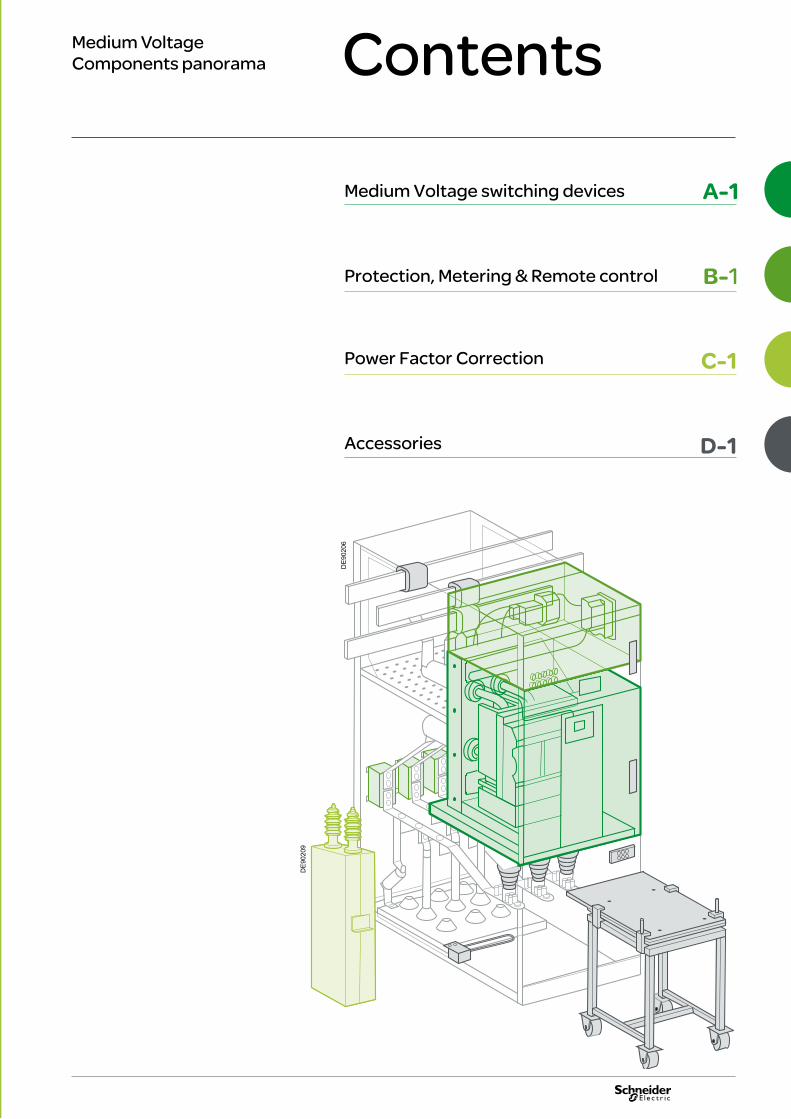
ContentsMedium Voltage Components panorama
Medium Voltage switching devices A-1
Protection, Metering & Remote control B-1
Power Factor Correction C-1
Accessories D-1
DE
9020
6
DE
9020
9

A-0

Medium Voltage switching devices
Circuit-Breakers
Contactors
Switches & Disconnectors
Fuses
Medium VoltageComponents panorama
DE
9020
6_1
Circ
uit-
Brea
kers
- Co
ntac
tors
- Sw
itche
s & D
isco
nnec
tors
- Fu
ses -
Pro
tect
ion
rela
ys -
Arc
faul
t det
ecto
rs -
MV
inst
rum
ent t
rans
form
ers -
Ene
rgy
man
agem
ent &
con
trol
- LV
pro
tect
ion
- Dire
ct C
urre
nt P
ower
supp
ly
- LV
rela
ys -
LV C
ontr
ol &
Sig
nalli
ng -
Subs
tatio
n re
mot
e co
ntro
l and
mon
itorin
g &
Fau
lt in
dica
tors
-
Subs
tati
on p
ower
sup
ply
- Cap
acito
rs &
Pow
er F
acto
r con
trol
ler -
Rel
ay &
Sw
itchi
ng d
evic
es -
Acc
esso
ries
A-1
A-2A-6A-8A-9

Medium Voltage switching devices
Circuit-Breakers
Vacuum Circuit-BreakersHVX HVX - Embedded pole Evolis Evolis VAH VXA/VXB VXC
Functions Functions
Protection and operation of network Protection and operation of network
Rated voltage Rated voltage
40.5 kV36 kV 38 kV
27,5 kV24 kV 24 kV 24 kV
17.5 kV 17.5 kV 17.5 kV 17.5 kV
12 kV 12 kV 12 kV 12 kV 12 kV
Max. rated short-circuit current Max. rated short-circuit current
50 kA 50 kA 31,5 kA 31.5 kA 31.5 kA 50 kA 31.5 kA 31.5 kA 31.5 kA 31.5 kA 31.5 kA 31.5 kA 25 kA 63 kA* / 160 kA
63 kA* / 160 kA
40 kA / 100 kA 40 kA
Max. rated current Max. rated current
3150 A 3150 A 2500 A 2500 A 2500 A 3150 A 3150 A 2500 A 2500 A 2500 A 2500 A 2500 A 1250 A 8000 A 8000 A 2500 A 2500 A
Versions Versions• Fixed • Withdrawable
• Fixed • Withdrawable• Roll on floor
• Fixed • Withdrawable
• Fixed • Withdrawable
• Fixed • Withdrawable
• Fixed • Withdrawable
• Fixed • Fixed • Withdrawable
• Fixed • Roll on floor
• Fixed • Withdrawable
Number of poles Number of poles
3p 3p 3p 3p 3p 3p 3p 1p & 2p 3p
Mechanical switching cycles (ON/OFF) Mechanical switching cycles (ON/OFF)
10000 10000 10000 10000 10000 10000 10000 10000 10000 10000 10000/25000
Mounting Mounting
Front Front Front Front Front Front Side Front Front Front
Mechanism Mechanism
Conventional spring Conventional spring Conventional spring Conventional spring Conventional spring Conventional spring Conventional spring Conventional spring Conventional spring
IEC, ANSI, GB (chinese) standards
IEC standards IEC, GB (chinese) standards
IEC, GB (chinese), GOST standards
IEC standards IEC standards IEC & ANSI standards*ANSI / IEEE C37.013 Generator Switching 63 kA, 4000 & 5000 A
IEC standards IEC standards
Benefits• Suited for Oil & Gas and nuclear powerplant application• Cradle with integrated earthing switch available for withdrawable version
• Compact dimensions• Marine solutions certified
Embedded pole for better dielectric & environmental pollution withstand
Embedded pole for better dielectric & environmental pollution withstand
Marine solutions certified VIP integrated trip unit for side version
For generator applications up to 130 MVA
For railways applications The arc furnace circuit breaker with high switching numbers, maintenance free up to 25,000 / 75,000 cycles
PE
9023
6
PE
9053
3
PE
9053
0
DE
9021
7
PE
5799
4
A-2

Vacuum Circuit-BreakersHVX HVX - Embedded pole Evolis Evolis VAH VXA/VXB VXC
Functions Functions
Protection and operation of network Protection and operation of network
Rated voltage Rated voltage
40.5 kV36 kV 38 kV
27,5 kV24 kV 24 kV 24 kV
17.5 kV 17.5 kV 17.5 kV 17.5 kV
12 kV 12 kV 12 kV 12 kV 12 kV
Max. rated short-circuit current Max. rated short-circuit current
50 kA 50 kA 31,5 kA 31.5 kA 31.5 kA 50 kA 31.5 kA 31.5 kA 31.5 kA 31.5 kA 31.5 kA 31.5 kA 25 kA 63 kA* / 160 kA
63 kA* / 160 kA
40 kA / 100 kA 40 kA
Max. rated current Max. rated current
3150 A 3150 A 2500 A 2500 A 2500 A 3150 A 3150 A 2500 A 2500 A 2500 A 2500 A 2500 A 1250 A 8000 A 8000 A 2500 A 2500 A
Versions Versions• Fixed • Withdrawable
• Fixed • Withdrawable• Roll on floor
• Fixed • Withdrawable
• Fixed • Withdrawable
• Fixed • Withdrawable
• Fixed • Withdrawable
• Fixed • Fixed • Withdrawable
• Fixed • Roll on floor
• Fixed • Withdrawable
Number of poles Number of poles
3p 3p 3p 3p 3p 3p 3p 1p & 2p 3p
Mechanical switching cycles (ON/OFF) Mechanical switching cycles (ON/OFF)
10000 10000 10000 10000 10000 10000 10000 10000 10000 10000 10000/25000
Mounting Mounting
Front Front Front Front Front Front Side Front Front Front
Mechanism Mechanism
Conventional spring Conventional spring Conventional spring Conventional spring Conventional spring Conventional spring Conventional spring Conventional spring Conventional spring
IEC, ANSI, GB (chinese) standards
IEC standards IEC, GB (chinese) standards
IEC, GB (chinese), GOST standards
IEC standards IEC standards IEC & ANSI standards*ANSI / IEEE C37.013 Generator Switching 63 kA, 4000 & 5000 A
IEC standards IEC standards
Benefits• Suited for Oil & Gas and nuclear powerplant application• Cradle with integrated earthing switch available for withdrawable version
• Compact dimensions• Marine solutions certified
Embedded pole for better dielectric & environmental pollution withstand
Embedded pole for better dielectric & environmental pollution withstand
Marine solutions certified VIP integrated trip unit for side version
For generator applications up to 130 MVA
For railways applications The arc furnace circuit breaker with high switching numbers, maintenance free up to 25,000 / 75,000 cycles
PE
9023
9
PE
9028
4
PE
9023
8
PE
5800
1
A-3
Medium Voltage switching devices
Circuit-Breakers
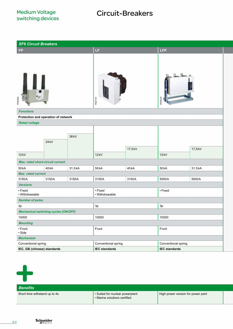
SF6 Circuit BreakersFP LF LFP SF1 SF2
Functions Functions
Protection and operation of network Protection and operation of network
Rated voltage Rated voltage
40,5 kV36 kV 36 kV 36 kV
24 kV 24 kV
17,5 kV 17,5 kV 17,5 kV
12 kV 12 kV 12 kV 12 kV
Max. rated short-circuit current Max. rated short-circuit current
50 kA 40 kA 31.5 kA 50 kA 40 kA 50 kA 31.5 kA 25 kA 25 kA 25 kA 25 kA 40 kA 31.5 kA
Max. rated current Max. rated current3150 A 3150 A 3150 A 3150 A 3150 A 5000 A 5000 A 1250 A 1250 A 1250 A 1250 A 3150 A 2500 A
Versions Versions
• Fixed • Withdrawable
• Fixed • Withdrawable
• Fixed • Fixed • Fixed• Withdrawable
Number of poles Number of poles
3p 3p 3p 3p 3p
Mechanical switching cycles (ON/OFF) Mechanical switching cycles (ON/OFF)
10000 10000 10000 10000 10000
Mounting Mounting
• Front • Side
Front Front • Front • Side
Front
Mechanism MechanismConventional spring Conventional spring Conventional spring Conventional spring Conventional spring
IEC, GB (chinese) standards IEC standards IEC standards IEC standards IEC standards
PE
9050
8
PE
5719
1
PE
9023
0
BenefitsShort time withstand up to 4s • Suited for nuclear powerplant
• Marine solutions certifiedHigh power version for power pant • Integrated VIP trip unit (without auxiliary power supply) in SFset up to
24 kV (for side mounted)• Suited for capacitor bank application
High energy mechanism (230 J) to open at high voltage ratings
A-4

SF6 Circuit BreakersFP LF LFP SF1 SF2
Functions Functions
Protection and operation of network Protection and operation of network
Rated voltage Rated voltage
40,5 kV36 kV 36 kV 36 kV
24 kV 24 kV
17,5 kV 17,5 kV 17,5 kV
12 kV 12 kV 12 kV 12 kV
Max. rated short-circuit current Max. rated short-circuit current
50 kA 40 kA 31.5 kA 50 kA 40 kA 50 kA 31.5 kA 25 kA 25 kA 25 kA 25 kA 40 kA 31.5 kA
Max. rated current Max. rated current3150 A 3150 A 3150 A 3150 A 3150 A 5000 A 5000 A 1250 A 1250 A 1250 A 1250 A 3150 A 2500 A
Versions Versions
• Fixed • Withdrawable
• Fixed • Withdrawable
• Fixed • Fixed • Fixed• Withdrawable
Number of poles Number of poles
3p 3p 3p 3p 3p
Mechanical switching cycles (ON/OFF) Mechanical switching cycles (ON/OFF)
10000 10000 10000 10000 10000
Mounting Mounting
• Front • Side
Front Front • Front • Side
Front
Mechanism MechanismConventional spring Conventional spring Conventional spring Conventional spring Conventional spring
IEC, GB (chinese) standards IEC standards IEC standards IEC standards IEC standards
PE
9023
2
PE
5650
1
BenefitsShort time withstand up to 4s • Suited for nuclear powerplant
• Marine solutions certifiedHigh power version for power pant • Integrated VIP trip unit (without auxiliary power supply) in SFset up to
24 kV (for side mounted)• Suited for capacitor bank application
High energy mechanism (230 J) to open at high voltage ratings
A-5
Medium Voltage switching devices
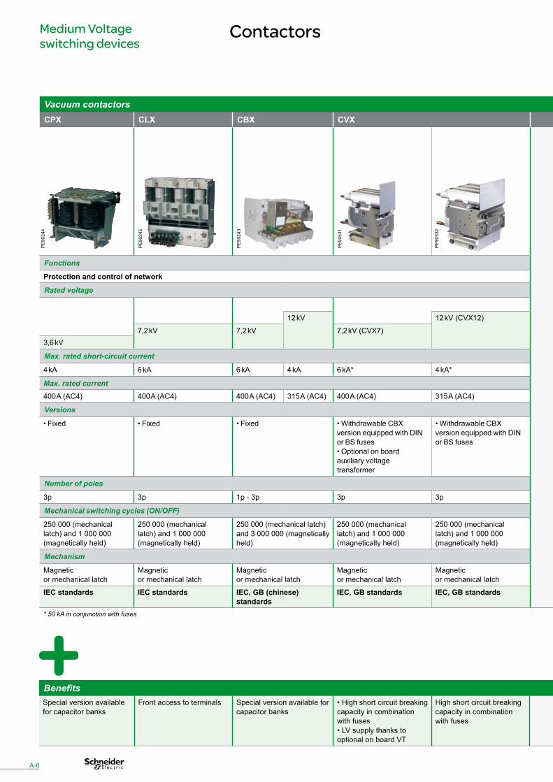
Contactors
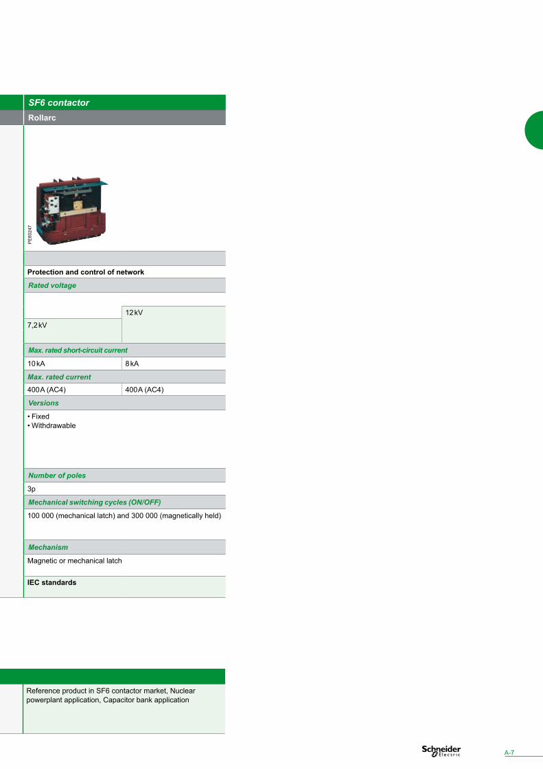
Vacuum contactors SF6 contactorCPX CLX CBX CVX Rollarc
Functions
Protection and control of network Protection and control of network
Rated voltage Rated voltage
12 kV 12 kV (CVX12) 12 kV
7,2 kV 7,2 kV 7,2 kV (CVX7) 7,2 kV3,6 kV
Max. rated short-circuit current Max. rated short-circuit current
4 kA 6 kA 6 kA 4 kA 6 kA* 4 kA* 10 kA 8 kA
Max. rated current Max. rated current400 A (AC4) 400 A (AC4) 400 A (AC4) 315 A (AC4) 400 A (AC4) 315 A (AC4) 400 A (AC4) 400 A (AC4)
Versions Versions
• Fixed • Fixed • Fixed • Withdrawable CBX version equipped with DIN or BS fuses• Optional on board auxiliary voltage transformer
• Withdrawable CBX version equipped with DIN or BS fuses
• Fixed • Withdrawable
Number of poles Number of poles
3p 3p 1p - 3p 3p 3p 3p
Mechanical switching cycles (ON/OFF) Mechanical switching cycles (ON/OFF)
250 000 (mechanical latch) and 1 000 000 (magnetically held)
250 000 (mechanical latch) and 1 000 000 (magnetically held)
250 000 (mechanical latch) and 3 000 000 (magnetically held)
250 000 (mechanical latch) and 1 000 000 (magnetically held)
250 000 (mechanical latch) and 1 000 000 (magnetically held)
100 000 (mechanical latch) and 300 000 (magnetically held)
Mechanism Mechanism
Magnetic or mechanical latch
Magnetic or mechanical latch
Magnetic or mechanical latch
Magnetic or mechanical latch
Magnetic or mechanical latch
Magnetic or mechanical latch
IEC standards IEC standards IEC, GB (chinese) standards
IEC, GB standards IEC, GB standards IEC standards
* 50 kA in conjunction with fuses
PE
9053
1
PE
9024
4
PE
9024
3
BenefitsSpecial version available for capacitor banks
Front access to terminals Special version available for capacitor banks
• High short circuit breaking capacity in combination with fuses• LV supply thanks to optional on board VT
High short circuit breaking capacity in combination with fuses
Reference product in SF6 contactor market, Nuclear powerplant application, Capacitor bank application
PE
9053
2
PE
9024
5
A-6
Vacuum contactors SF6 contactorCPX CLX CBX CVX Rollarc
Functions
Protection and control of network Protection and control of network
Rated voltage Rated voltage
12 kV 12 kV (CVX12) 12 kV
7,2 kV 7,2 kV 7,2 kV (CVX7) 7,2 kV3,6 kV
Max. rated short-circuit current Max. rated short-circuit current
4 kA 6 kA 6 kA 4 kA 6 kA* 4 kA* 10 kA 8 kA
Max. rated current Max. rated current400 A (AC4) 400 A (AC4) 400 A (AC4) 315 A (AC4) 400 A (AC4) 315 A (AC4) 400 A (AC4) 400 A (AC4)
Versions Versions
• Fixed • Fixed • Fixed • Withdrawable CBX version equipped with DIN or BS fuses• Optional on board auxiliary voltage transformer
• Withdrawable CBX version equipped with DIN or BS fuses
• Fixed • Withdrawable
Number of poles Number of poles
3p 3p 1p - 3p 3p 3p 3p
Mechanical switching cycles (ON/OFF) Mechanical switching cycles (ON/OFF)
250 000 (mechanical latch) and 1 000 000 (magnetically held)
250 000 (mechanical latch) and 1 000 000 (magnetically held)
250 000 (mechanical latch) and 3 000 000 (magnetically held)
250 000 (mechanical latch) and 1 000 000 (magnetically held)
250 000 (mechanical latch) and 1 000 000 (magnetically held)
100 000 (mechanical latch) and 300 000 (magnetically held)
Mechanism Mechanism
Magnetic or mechanical latch
Magnetic or mechanical latch
Magnetic or mechanical latch
Magnetic or mechanical latch
Magnetic or mechanical latch
Magnetic or mechanical latch
IEC standards IEC standards IEC, GB (chinese) standards
IEC, GB standards IEC, GB standards IEC standards
* 50 kA in conjunction with fuses
PE
6024
7
BenefitsSpecial version available for capacitor banks
Front access to terminals Special version available for capacitor banks
• High short circuit breaking capacity in combination with fuses• LV supply thanks to optional on board VT
High short circuit breaking capacity in combination with fuses
Reference product in SF6 contactor market, Nuclear powerplant application, Capacitor bank application
A-7
Medium Voltage switching devices
Switches & Disconnectors
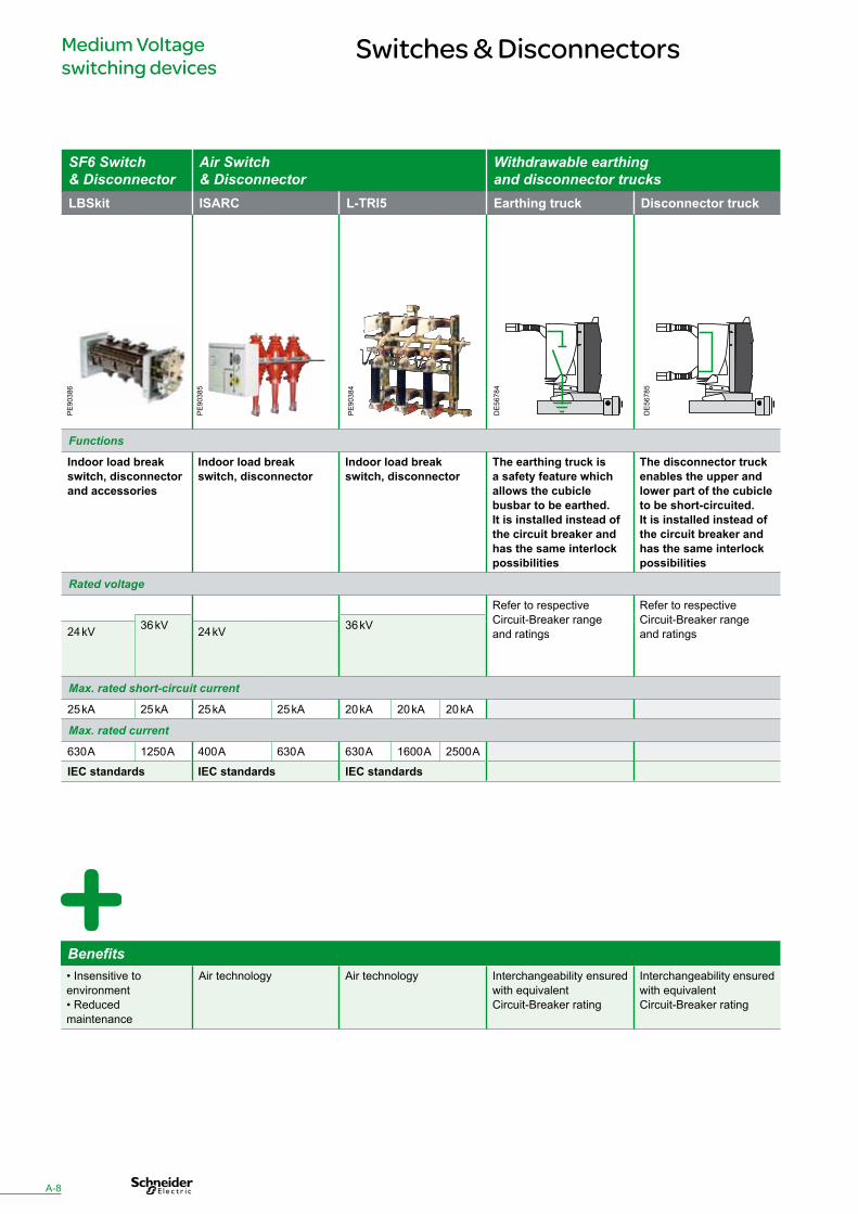
SF6 Switch & Disconnector
Air Switch & Disconnector
Withdrawable earthing and disconnector trucks
LBSkit ISARC L-TRI5 Earthing truck Disconnector truck
Functions
Indoor load break switch, disconnector and accessories
Indoor load break switch, disconnector
Indoor load break switch, disconnector
The earthing truck is a safety feature which allows the cubicle busbar to be earthed.It is installed instead of the circuit breaker and has the same interlock possibilities
The disconnector truck enables the upper and lower part of the cubicleto be short-circuited. It is installed instead of the circuit breaker andhas the same interlock possibilities
Rated voltage
Refer to respective Circuit-Breaker range and ratings
Refer to respective Circuit-Breaker range and ratings
36 kV 36 kV24 kV 24 kV
Max. rated short-circuit current
25 kA 25 kA 25 kA 25 kA 20 kA 20 kA 20 kA
Max. rated current
630 A 1250 A 400 A 630 A 630 A 1600 A 2500 A
IEC standards IEC standards IEC standards
DE
5678
4
PE
9038
4
PE
9038
5
PE
9038
6
DE
5678
5
Benefits• Insensitive to environment• Reduced maintenance
Air technology Air technology Interchangeability ensured with equivalent Circuit-Breaker rating
Interchangeability ensured with equivalent Circuit-Breaker rating
A-8
Medium Voltage switching devices
Fuses
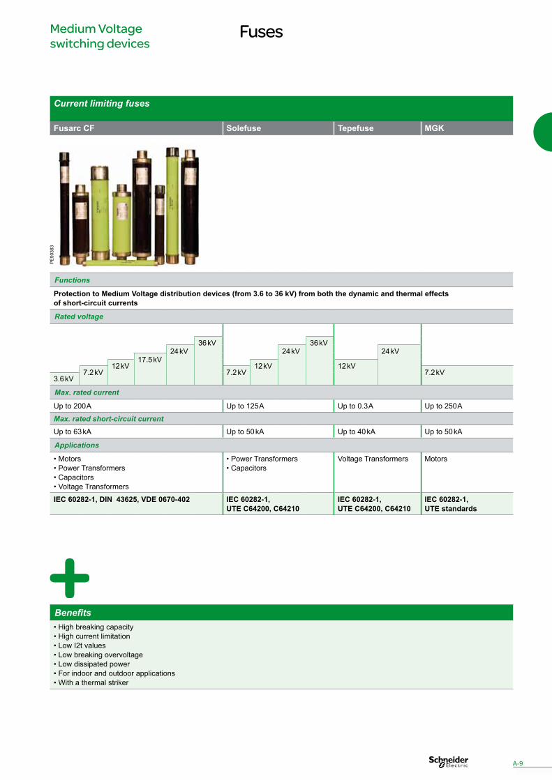
Current limiting fuses
Fusarc CF Solefuse Tepefuse MGK
Functions
Protection to Medium Voltage distribution devices (from 3.6 to 36 kV) from both the dynamic and thermal effects of short-circuit currents
Rated voltage
36 kV 36 kV24 kV 24 kV 24 kV
17.5 kV12 kV 12 kV 12 kV
7.2 kV 7.2 kV 7.2 kV3.6 kV
Max. rated current
Up to 200 A Up to 125 A Up to 0.3 A Up to 250 A
Max. rated short-circuit currentUp to 63 kA Up to 50 kA Up to 40 kA Up to 50 kA
Applications
• Motors• Power Transformers• Capacitors• Voltage Transformers
• Power Transformers• Capacitors
Voltage Transformers Motors
IEC 60282-1, DIN 43625, VDE 0670-402 IEC 60282-1, UTE C64200, C64210
IEC 60282-1, UTE C64200, C64210
IEC 60282-1, UTE standards
PE
9038
3
Benefits• High breaking capacity• High current limitation• Low I2t values• Low breaking overvoltage• Low dissipated power• For indoor and outdoor applications• With a thermal striker
A-9
B-0

Protection, Metering & Remote control
Protection relays
Arc fault detectors
Medium Voltage instrument transformers
Energy management & control
Low Voltage protection
Direct Current Power Supply
Low Voltage relays
Low Voltage Control & Signalling
Substation remote control and monitoring & Fault indicators
Substation power supply
Medium VoltageComponents panorama
DE
9020
6_2
Circ
uit-
Brea
kers
- Co
ntac
tors
- Sw
itche
s & D
isco
nnec
tors
- Fu
ses -
Pro
tect
ion
rela
ys -
Arc
faul
t det
ecto
rs -
MV
inst
rum
ent t
rans
form
ers -
Ene
rgy
man
agem
ent &
con
trol
- LV
pro
tect
ion
- Dire
ct C
urre
nt P
ower
supp
ly
- LV
rela
ys -
LV C
ontr
ol &
Sig
nalli
ng -
Subs
tatio
n re
mot
e co
ntro
l and
mon
itorin
g &
Fau
lt in
dica
tors
-
Subs
tati
on p
ower
sup
ply
- Ca
paci
tors
& P
ower
Fac
tor c
ontr
olle
r - R
elay
& S
witc
hing
dev
ices
- A
cces
sorie
s
B-1
B-2B-4B-5B-6B-9B-10B-11B-12
B-16B-17
Protection, Metering & Remote control
Protection relays
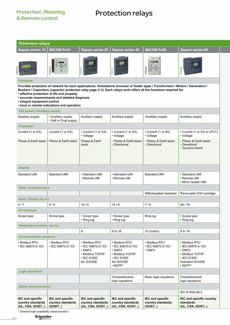
Protection relaysSepam series 10 MiCOM Px10 Sepam series 20 Sepam series 40 MiCOM Px20 Sepam series 60 Sepam series 80 MiCOM Px30 MiCOM Px40
Functions FunctionsProvides protection of network for each applications: Substations (incomer or feeder type) / Transformers / Motors / Generators / Busbars / Capacitors (capacitor protection relay page C-3). Each relays serie offers all the functions required for:• effective protection of life and property• accurate measurements and detailed diagnosis• integral equipment control• local or remote indications and operation
Self power / Auxiliary supply Self power / Auxiliary supply
Auxiliary supply • Auxiliary supply• Self or Dual supply
Auxiliary supply Auxiliary supply Auxiliary supply Auxiliary supply Auxiliary supply Auxiliary supply Auxiliary supply
Protection Protection
Current (1 or 5 A) Current (1 or 5 A) • Current (1 or 5 A)• Voltage
• Current (1 or 5 A)• Voltage
• Current (1 or 5A)• Voltage
• Current (1 or 5 A or LPCT)• Voltage
• Current (1 or 5 A or LPCT)• Voltage
• Current (1 or 5A)• Voltage
• Current (1 or 5A)• Voltage
Phase & Earth basic Phase & Earth basic Phase & Earth basic
- Phase & Earth basic- Directional
- Phase & Earth basic- Directional
- Phase & Earth basic- Directional- Synchro-check
- Phase & Earth basic- Directional- Synchro-check- Differential
- Phase & Earth basic- Directional- Synchro-check- Differential- Line differential- Distance
- Phase & Earth basic- Directional- Synchro-check- Differential- Line differential- Distance- Busbar differential
Display Display
Standard UMI Standard UMI • Standard UMI• Remote UM
• Standard UMI• Remote UM
Standard UMI • Standard UMI• Remote UM• Mimic based UMI
• Standard UMI• Remote UM• Mimic based UMI
• Standard UMI• Remote UM• Mimic based UMI
• Standard UMI
Other characteristics Other characteristics
Withdrawable hardware Removable S/W cartridge Removable S/W cartridge
Input / Output (up to) Input / Output (up to)
4 / 7 6 / 6 10 / 8 10 / 8 7 / 8 28 / 16 42 / 23 50 / 26 32 / 32
I/O terminals I/O terminals
Screw type Screw type • Screw type• Ring lug
• Screw type• Ring lug
Ring lug • Screw type• Ring lug
• Screw type• Ring lug
• Screw type• Ring lug
Ring lug
Temperature sensor (up to) Temperature sensor (up to)
8 8 to 16 10 (motor) 8 to 16 8 to 16 1 / 9 / 10 10
Communication protocol Communication protocol
• Modbus RTU• IEC 60870-5-103
• Modbus RTU• IEC 60870-5-103
• Modbus RTU• IEC 60870-5-103• DNP3• Modbus TCP/IP• IEC 61850 No GOOSE
• Modbus RTU• IEC 60870-5-103• DNP3• Modbus TCP/IP• IEC 61850 No GOOSE• RSTP*
• Modbus RTU• IEC 60870-5-103• DNP3
• Modbus RTU• IEC 60870-5-103• DNP3• Modbus TCP/IP• IEC 61850 Standard GOOSE• RSTP*
• Modbus RTU• IEC 60870-5-103• DNP3• Modbus TCP/IP• IEC 61850 Customized GOOSE• RSTP*
• Modbus RTU• IEC 60870-5-103• DNP3• IEC 61850 with GOOSE• RSTP / SHP / DHP*
• Modbus RTU• IEC 60870-5-103• DNP3• IEC 61850 with GOOSE• RSTP / SHP / DHP*
Logic equations Logic equations
Comprehensive logic equations
Basic logic equations Comprehensive logic equations
Control logic by ladder diagram
Comprehensive logic equations
Comprehensive logic equations
Safety characteristics Safety characteristics
IEC 61508-SIL2 IEC 61508 - SIL2
IEC and specific country standards(UL, CSA, GOST...)
IEC and specific country standards(GOST...)
IEC and specific country standards(UL, CSA, GOST...)
IEC and specific country standards(UL, CSA, GOST...)
IEC and specific country standards(GOST...)
IEC and specific country standards(UL, CSA, GOST...)
IEC and specific country standards(UL, CSA, GOST...)
IEC and specific country standards (GOST...)
IEC and specific country standards (GOST...)
* Ethernet high availability communication
PE
9036
6
PE
9043
8
PE
9051
0
B-2
PE
9048
8
PE
9051
1
PE
9051
1

Protection relaysSepam series 10 MiCOM Px10 Sepam series 20 Sepam series 40 MiCOM Px20 Sepam series 60 Sepam series 80 MiCOM Px30 MiCOM Px40
Functions FunctionsProvides protection of network for each applications: Substations (incomer or feeder type) / Transformers / Motors / Generators / Busbars / Capacitors (capacitor protection relay page C-3). Each relays serie offers all the functions required for:• effective protection of life and property• accurate measurements and detailed diagnosis• integral equipment control• local or remote indications and operation
Self power / Auxiliary supply Self power / Auxiliary supply
Auxiliary supply • Auxiliary supply• Self or Dual supply
Auxiliary supply Auxiliary supply Auxiliary supply Auxiliary supply Auxiliary supply Auxiliary supply Auxiliary supply
Protection Protection
Current (1 or 5 A) Current (1 or 5 A) • Current (1 or 5 A)• Voltage
• Current (1 or 5 A)• Voltage
• Current (1 or 5A)• Voltage
• Current (1 or 5 A or LPCT)• Voltage
• Current (1 or 5 A or LPCT)• Voltage
• Current (1 or 5A)• Voltage
• Current (1 or 5A)• Voltage
Phase & Earth basic Phase & Earth basic Phase & Earth basic
- Phase & Earth basic- Directional
- Phase & Earth basic- Directional
- Phase & Earth basic- Directional- Synchro-check
- Phase & Earth basic- Directional- Synchro-check- Differential
- Phase & Earth basic- Directional- Synchro-check- Differential- Line differential- Distance
- Phase & Earth basic- Directional- Synchro-check- Differential- Line differential- Distance- Busbar differential
Display Display
Standard UMI Standard UMI • Standard UMI• Remote UM
• Standard UMI• Remote UM
Standard UMI • Standard UMI• Remote UM• Mimic based UMI
• Standard UMI• Remote UM• Mimic based UMI
• Standard UMI• Remote UM• Mimic based UMI
• Standard UMI
Other characteristics Other characteristics
Withdrawable hardware Removable S/W cartridge Removable S/W cartridge
Input / Output (up to) Input / Output (up to)
4 / 7 6 / 6 10 / 8 10 / 8 7 / 8 28 / 16 42 / 23 50 / 26 32 / 32
I/O terminals I/O terminals
Screw type Screw type • Screw type• Ring lug
• Screw type• Ring lug
Ring lug • Screw type• Ring lug
• Screw type• Ring lug
• Screw type• Ring lug
Ring lug
Temperature sensor (up to) Temperature sensor (up to)
8 8 to 16 10 (motor) 8 to 16 8 to 16 1 / 9 / 10 10
Communication protocol Communication protocol
• Modbus RTU• IEC 60870-5-103
• Modbus RTU• IEC 60870-5-103
• Modbus RTU• IEC 60870-5-103• DNP3• Modbus TCP/IP• IEC 61850 No GOOSE
• Modbus RTU• IEC 60870-5-103• DNP3• Modbus TCP/IP• IEC 61850 No GOOSE• RSTP*
• Modbus RTU• IEC 60870-5-103• DNP3
• Modbus RTU• IEC 60870-5-103• DNP3• Modbus TCP/IP• IEC 61850 Standard GOOSE• RSTP*
• Modbus RTU• IEC 60870-5-103• DNP3• Modbus TCP/IP• IEC 61850 Customized GOOSE• RSTP*
• Modbus RTU• IEC 60870-5-103• DNP3• IEC 61850 with GOOSE• RSTP / SHP / DHP*
• Modbus RTU• IEC 60870-5-103• DNP3• IEC 61850 with GOOSE• RSTP / SHP / DHP*
Logic equations Logic equations
Comprehensive logic equations
Basic logic equations Comprehensive logic equations
Control logic by ladder diagram
Comprehensive logic equations
Comprehensive logic equations
Safety characteristics Safety characteristics
IEC 61508-SIL2 IEC 61508 - SIL2
IEC and specific country standards(UL, CSA, GOST...)
IEC and specific country standards(GOST...)
IEC and specific country standards(UL, CSA, GOST...)
IEC and specific country standards(UL, CSA, GOST...)
IEC and specific country standards(GOST...)
IEC and specific country standards(UL, CSA, GOST...)
IEC and specific country standards(UL, CSA, GOST...)
IEC and specific country standards (GOST...)
IEC and specific country standards (GOST...)
* Ethernet high availability communication
PE
9043
7
PE
9043
6
BenefitsSepam• Hardware modularity and common Hardware modules• Large range of auxiliary power• Full range ROHS and conformal coated
MiCOM• Complete and Comprehensive product offer• Full IEC 61850 solution with goose• All in the box solution
B-3
PE
9051
2
Protection, Metering & Remote control
Arc fault detectors
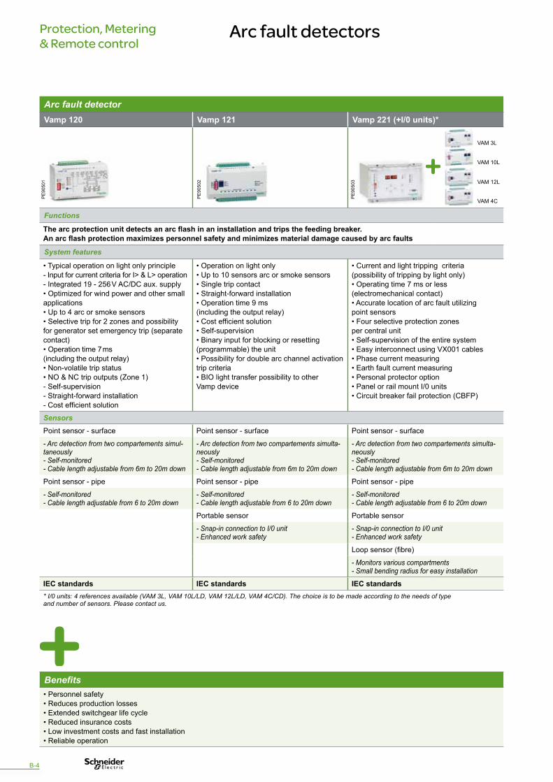
Benefits• Personnel safety• Reduces production losses• Extended switchgear life cycle• Reduced insurance costs• Low investment costs and fast installation• Reliable operation
B-4
Arc fault detectorVamp 120 Vamp 121 Vamp 221 (+I/0 units)*
Functions
The arc protection unit detects an arc flash in an installation and trips the feeding breaker.An arc flash protection maximizes personnel safety and minimizes material damage caused by arc faults
System features
• Typical operation on light only principle - Input for current criteria for I> & L> operation - Integrated 19 - 256 V AC/DC aux. supply • Optimized for wind power and other small applications • Up to 4 arc or smoke sensors • Selective trip for 2 zones and possibility for generator set emergency trip (separate contact) • Operation time 7 ms (including the output relay) • Non-volatile trip status • NO & NC trip outputs (Zone 1) - Self-supervision - Straight-forward installation - Cost efficient solution
• Operation on light only • Up to 10 sensors arc or smoke sensors • Single trip contact • Straight-forward installation • Operation time 9 ms (including the output relay) • Cost efficient solution • Self-supervision • Binary input for blocking or resetting (programmable) the unit • Possibility for double arc channel activation trip criteria • BIO light transfer possibility to other Vamp device
• Current and light tripping criteria (possibility of tripping by light only)• Operating time 7 ms or less (electromechanical contact)• Accurate location of arc fault utilizing point sensors• Four selective protection zones per central unit• Self-supervision of the entire system• Easy interconnect using VX001 cables• Phase current measuring• Earth fault current measuring• Personal protector option• Panel or rail mount I/0 units• Circuit breaker fail protection (CBFP)
SensorsPoint sensor - surface Point sensor - surface Point sensor - surface
- Arc detection from two compartements simul-taneously- Self-monitored- Cable length adjustable from 6m to 20m down
- Arc detection from two compartements simulta-neously- Self-monitored- Cable length adjustable from 6m to 20m down
- Arc detection from two compartements simulta-neously- Self-monitored- Cable length adjustable from 6m to 20m down
Point sensor - pipe Point sensor - pipe Point sensor - pipe
- Self-monitored- Cable length adjustable from 6 to 20m down
- Self-monitored- Cable length adjustable from 6 to 20m down
- Self-monitored- Cable length adjustable from 6 to 20m down
Portable sensor Portable sensor
- Snap-in connection to I/0 unit- Enhanced work safety
- Snap-in connection to I/0 unit- Enhanced work safety
Loop sensor (fibre)
- Monitors various compartments- Small bending radius for easy installation
IEC standards IEC standards IEC standards* I/0 units: 4 references available (VAM 3L, VAM 10L/LD, VAM 12L/LD, VAM 4C/CD). The choice is to be made according to the needs of type and number of sensors. Please contact us.
PE
9050
1
PE
9050
2
PE
9050
3
VAM 3L
VAM 10L
VAM 12L
VAM 4C
B-5
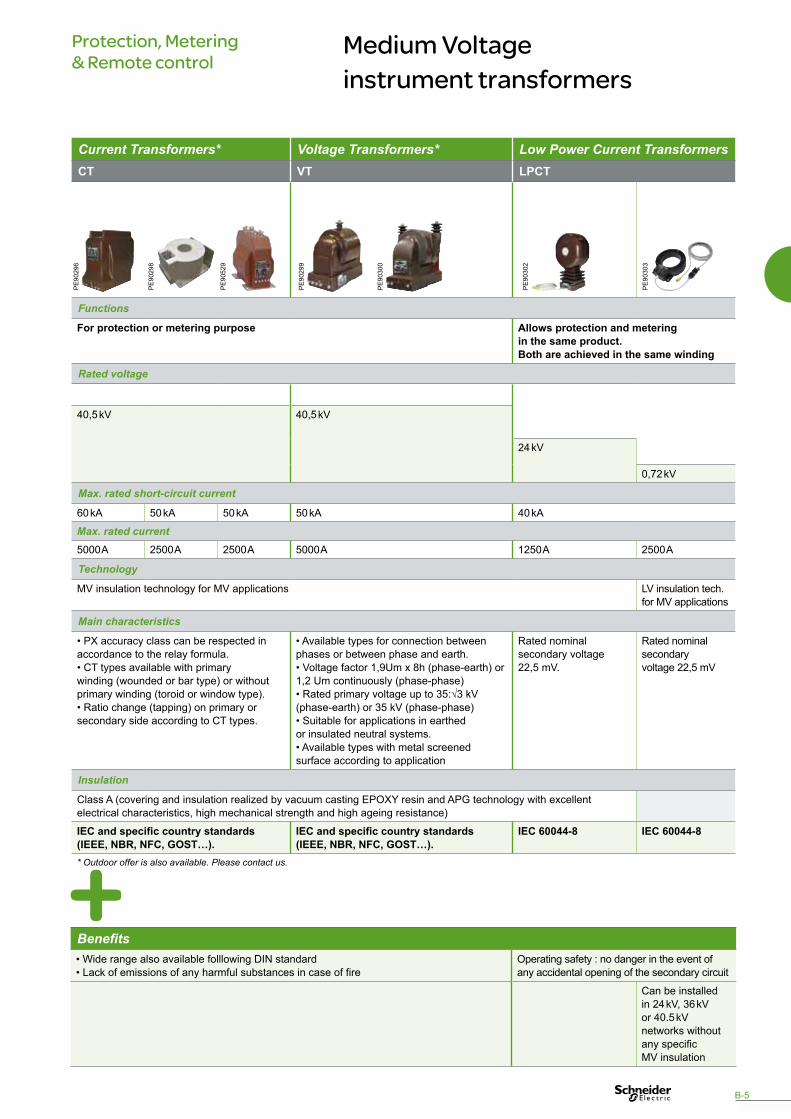
Current Transformers* Voltage Transformers* Low Power Current TransformersCT VT LPCT
Functions
For protection or metering purpose Allows protection and metering in the same product. Both are achieved in the same winding
Rated voltage
40,5 kV 40,5 kV
24 kV
0,72 kV
Max. rated short-circuit current
60 kA 50 kA 50 kA 50 kA 40 kA
Max. rated current5000 A 2500 A 2500 A 5000 A 1250 A 2500 A
Technology
MV insulation technology for MV applications LV insulation tech. for MV applications
Main characteristics
• PX accuracy class can be respected in accordance to the relay formula.• CT types available with primary winding (wounded or bar type) or without primary winding (toroid or window type).• Ratio change (tapping) on primary or secondary side according to CT types.
• Available types for connection between phases or between phase and earth.• Voltage factor 1,9Um x 8h (phase-earth) or 1,2 Um continuously (phase-phase)• Rated primary voltage up to 35:√3 kV (phase-earth) or 35 kV (phase-phase) • Suitable for applications in earthed or insulated neutral systems.• Available types with metal screened surface according to application
Rated nominalsecondary voltage22,5 mV.
Rated nominalsecondary voltage 22,5 mV
Insulation
Class A (covering and insulation realized by vacuum casting EPOXY resin and APG technology with excellent electrical characteristics, high mechanical strength and high ageing resistance)
IEC and specific country standards(IEEE, NBR, NFC, GOST…).
IEC and specific country standards(IEEE, NBR, NFC, GOST…).
IEC 60044-8 IEC 60044-8
* Outdoor offer is also available. Please contact us.
Protection, Metering & Remote control
Medium Voltage instrument transformers
PE
9029
6
PE
9029
8
PE
9052
9
PE
9030
2
PE
9030
3
Benefits• Wide range also available folllowing DIN standard• Lack of emissions of any harmful substances in case of fire
Operating safety : no danger in the event of any accidental opening of the secondary circuit
Can be installed in 24 kV, 36 kV or 40.5 kV networks without any specific MV insulation
PE
9029
9
PE
9030
0

Protection, Metering & Remote control
Energy management and control
Energy metering Power & Energy monitoringAMP - ammeter VLT - voltmeter PM9C PM710 PM750
Functions
Measures in amps the current flowing through an electrical circuit
Measures in volts the potential difference (voltage) of an electrical circuit
Offers the basic measurement capabilities required to monitor an electrical installation
Offers all the measurement capabilities required to monitor an electrical installation
• Flush mounted 72x72 - 96x96• 10 A direct currentmeasurement orvia external CT• Accuracy: class 1.5
• Flush mounted 72x72 - 96x96• 600 V AC directvoltage measurementor via external VT• Accuracy: class 1.5
• 4-module case (18 mm modules)• Energy accuracy: IEC 62053-21 class 1
• Panel front mounted 96x96• Energy accuracy: - PM710: IEC 62053-21 class 1- PM750: IEC 62053-22 class 0.5S
Instantaneous rms values
• Current, per phase & Neutral• Voltage: total, phase-to-neutral and phase-to-phase• Frequency• Power factor: Total • Active, reactive, partial active energy
• Current: Total, Phases & Neutral• Voltage: Total, Phase-to-neutral and phase-to-phase• Frequency• Power factor: Total - Signed• Active, reactive, partial active energy: Signed
Power quality measurements
Total harmonic distortion: Current, voltage, per phase
Data recording
• Min/max of instantaneous values• Alarms
CommunicationModbus RS485 protocol Modbus RS485 protocol • Modbus RS485 protocol
• 2 digital inputs• 1 digital output
Display
LCD LCD (features large 11 mm high characters and powerful backlighting for easy reading even in extreme lighting conditions viewing angles)
IEC 60051-1, IEC 61013-1, IEC 61000-4 IEC 61557-12, IEC 62053-21 class1
IEC 62053-21 class 1IEC 61557-12 PMD/S/K55/1
IEC 62053-22 class 0,5SIEC 61557-12 PMD/S/K55/0.5
BenefitsLocal measurements • Panel instrumentation
• Sub-billing / cost allocation• Remote monitoring of an electrical installation
• Panel instrumentation• Sub-billing / cost allocation• Remote monitoring of an electrical installation• Harmonic monitoring (THD)
PB
1011
18
PE
9049
1
PB
1006
46
PE
8615
7
B-6
B-7
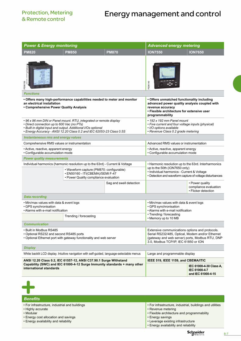
Power & Energy monitoring Advanced energy meteringPM820 PM850 PM870 ION7550 ION7650
Functions
• Offers many high-performance capabilities needed to meter and monitor an electrical installation• Comprehensive Power Quality Analysis
• Offers unmatched functionality including advanced power quality analysis coupled with revenue accuracy• Flexible architecture for extensive user programmability
• 96 x 96 mm DIN or Panel mount. RTU, integrated or remote display• Direct connection up to 600 Vac (no PTs)• Built in digital input and output. Additional I/Os optional• Energy Accuracy - ANSI 12.20 Class 0.2 and IEC 62053-23 Class 0.5S
• 192 x 192 mm Panel mount• Five current and four voltage inputs (physical)• I/O options available• Revenue Class 0.2 grade metering
Instantaneous rms and energy values
Comprehensive RMS values or instrumentation Advanced RMS values or instrumentation
• Active, reactive, apparent energy• Configurable accumulation mode
• Active, reactive, apparent energy• Configurable accumulation mode
Power quality measurementsIndividual harmonics (harmonic resolution up to the 63rd) - Current & Voltage • Harmonic resolution up to the 63rd. Interharmonics
up to the 50th (ION7650 only)• Individual harmonics - Current & Voltage• Detection and waveform capture of voltage disturbances
• Waveform capture (PM870: configurable)• EN50160 - ITI(CBEMA)/SEMI F-47• Power Quality compliance evaluation
Sag and swell detection • Power quality compliance evaluation • Flicker detection
Data recording
• Min/max values with data & event logs• GPS synchronisation• Alarms with e-mail notification
• Min/max values with data & event logs• GPS synchronisation• Alarms with e-mail notification• Trending / forecasting• Memory up to 10 MB
Trending / forecasting
Communication
• Built in Modbus RS485• Optional RS232 and second RS485 ports• Optional Ethernet port with gateway functionality and web server
Extensive communications options and protocols.Serial RS232/485, Optical, Modem and/or Ethernet (gateway and web server) ports, Modbus RTU, DNP 3.0, Modbus TCP/IP, IEC 61850 or ION
Display
White backlit LCD display. Intuitive navigation with self-guided, language-selectable menus Large and programmable display
ANSI 12.20 Class 0.2, IEC 61557-12, ANSI C37.90.1 Surge Withstand Capability (SWC) and IEC 61000-4-12 Surge Immunity standards + many other international standards
IEEE 519, IEEE 1159, and CBEMA/ITICIEC 61000-4-30 Class A, IEC 61000-4-7 and IEC 61000-4-15
PE
8614
9
PE
8615
8
Protection, Metering & Remote control
Energy management and control
Benefits• For infrastructure, industrial and buildings • Highly accurate• Modular • Energy cost allocation and savings• Energy availability and reliability
• For infrastructure, industrial, buildings and utilities • Revenue metering• Flexible architecture and programmability• Energy savings• Leverage existing infrastructure• Energy availability and reliability
Protection, Metering & Remote control
Energy management and control
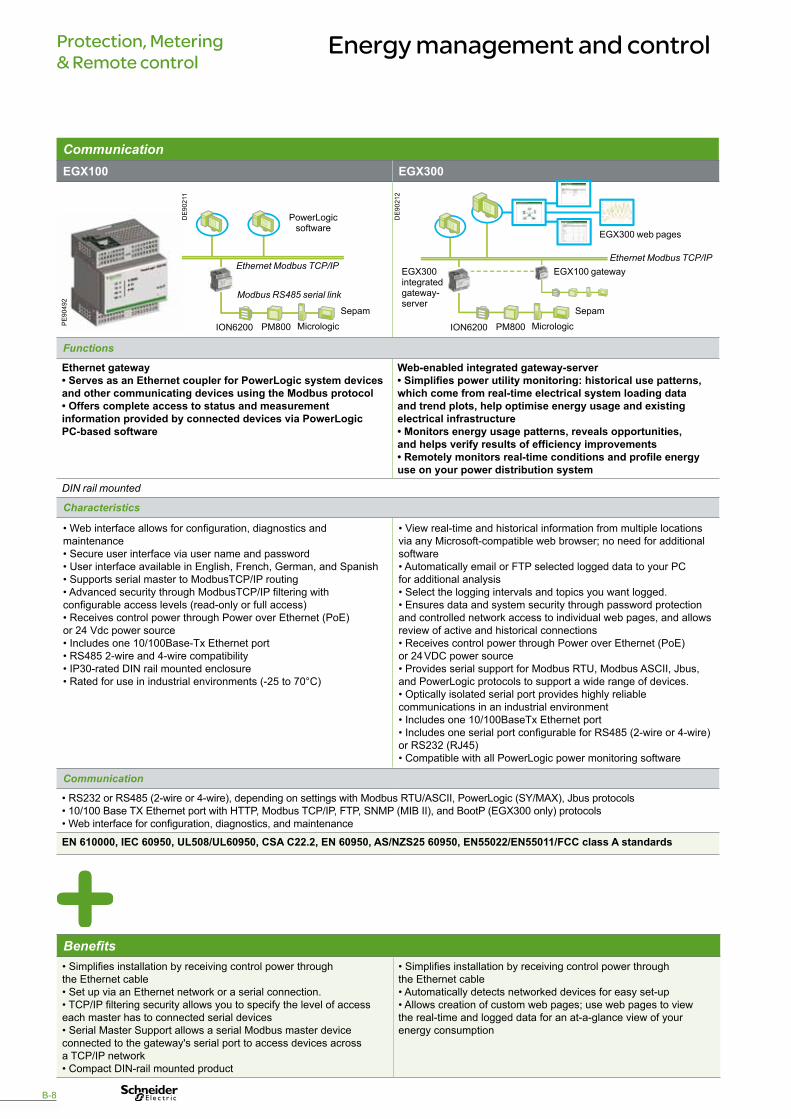
CommunicationEGX100 EGX300
Functions
Ethernet gateway• Serves as an Ethernet coupler for PowerLogic system devices and other communicating devices using the Modbus protocol• Offers complete access to status and measurement information provided by connected devices via PowerLogic PC-based software
Web-enabled integrated gateway-server• Simplifies power utility monitoring: historical use patterns, which come from real-time electrical system loading data and trend plots, help optimise energy usage and existing electrical infrastructure• Monitors energy usage patterns, reveals opportunities, and helps verify results of efficiency improvements• Remotely monitors real-time conditions and profile energy use on your power distribution system
DIN rail mounted
Characteristics
• Web interface allows for configuration, diagnostics and maintenance• Secure user interface via user name and password• User interface available in English, French, German, and Spanish• Supports serial master to ModbusTCP/IP routing• Advanced security through ModbusTCP/IP filtering with configurable access levels (read-only or full access)• Receives control power through Power over Ethernet (PoE) or 24 Vdc power source• Includes one 10/100Base-Tx Ethernet port• RS485 2-wire and 4-wire compatibility• IP30-rated DIN rail mounted enclosure• Rated for use in industrial environments (-25 to 70°C)
• View real-time and historical information from multiple locations via any Microsoft-compatible web browser; no need for additional software• Automatically email or FTP selected logged data to your PC for additional analysis• Select the logging intervals and topics you want logged.• Ensures data and system security through password protection and controlled network access to individual web pages, and allows review of active and historical connections• Receives control power through Power over Ethernet (PoE) or 24 VDC power source• Provides serial support for Modbus RTU, Modbus ASCII, Jbus, and PowerLogic protocols to support a wide range of devices.• Optically isolated serial port provides highly reliable communications in an industrial environment• Includes one 10/100BaseTx Ethernet port• Includes one serial port configurable for RS485 (2-wire or 4-wire) or RS232 (RJ45)• Compatible with all PowerLogic power monitoring software
Communication
• RS232 or RS485 (2-wire or 4-wire), depending on settings with Modbus RTU/ASCII, PowerLogic (SY/MAX), Jbus protocols• 10/100 Base TX Ethernet port with HTTP, Modbus TCP/IP, FTP, SNMP (MIB II), and BootP (EGX300 only) protocols• Web interface for configuration, diagnostics, and maintenance
EN 610000, IEC 60950, UL508/UL60950, CSA C22.2, EN 60950, AS/NZS25 60950, EN55022/EN55011/FCC class A standards
PowerLogicsoftware
Ethernet Modbus TCP/IPEthernet Modbus TCP/IP
Modbus RS485 serial link
ION6200 ION6200PM800 PM800Micrologic MicrologicSepam Sepam
EGX100 gatewayEGX300 integrated gateway- server
EGX300 web pages
Benefits• Simplifies installation by receiving control power through the Ethernet cable• Set up via an Ethernet network or a serial connection.• TCP/IP filtering security allows you to specify the level of access each master has to connected serial devices• Serial Master Support allows a serial Modbus master device connected to the gateway's serial port to access devices across a TCP/IP network• Compact DIN-rail mounted product
• Simplifies installation by receiving control power through the Ethernet cable• Automatically detects networked devices for easy set-up• Allows creation of custom web pages; use web pages to view the real-time and logged data for an at-a-glance view of your energy consumption
PE
9049
2
DE
9021
1
DE
9021
2
B-8

B-9
Protection, Metering & Remote control
Low Voltage protection
Low Voltage protectionC60N C60HDC C60 Electrical auxiliairies
OF SD
Functions
DIN rail miniature circuit-breakers. Circuit-Breaker used in auxiliary power supply circuits providing overload and short circuit protection
Open/closed contact Fault signalisation contact
Rated voltage
12 to 240 VAC (Ph/N) 250 VDC/pole • 24...415 VAC• 24...130 VDC
Number of poles
1, 2, 3, 4 1 or 2
Breaking capacity
10 kA at 240 VAC 6 kA at 250 VDC
Nominal current Maximum operating current
0.5 to 63 A • 6 A at U ≤ 240 VAC & 3 A at U ≤ 415 VAC• 6 A at U = 24 VDC, 2 A at U ≤ 48 VDC, 1 A at U ≤ 130 VDC
Type ol loads/ Tripping curve*
B, C, D C
ConnectionScrewIEC 947-2
* Tripping Curve Type of loads C (5In<Im<10In) Standard D (10In<Im<14In) Inrush current B (3In<Im<5In Electronics or high cable length
BenefitsThe Multi9 circuit-breaker is recognised in over 100 countries for its quality and the breadth of its range, making it an indispensable component for your Low Voltage cabinet with complete peace of mind
PB
1040
14
PE
9050
5
PE
9050
4
PB
1002
21
0540
47_S
E
Protection, Metering & Remote control
Direct Current Power Supply
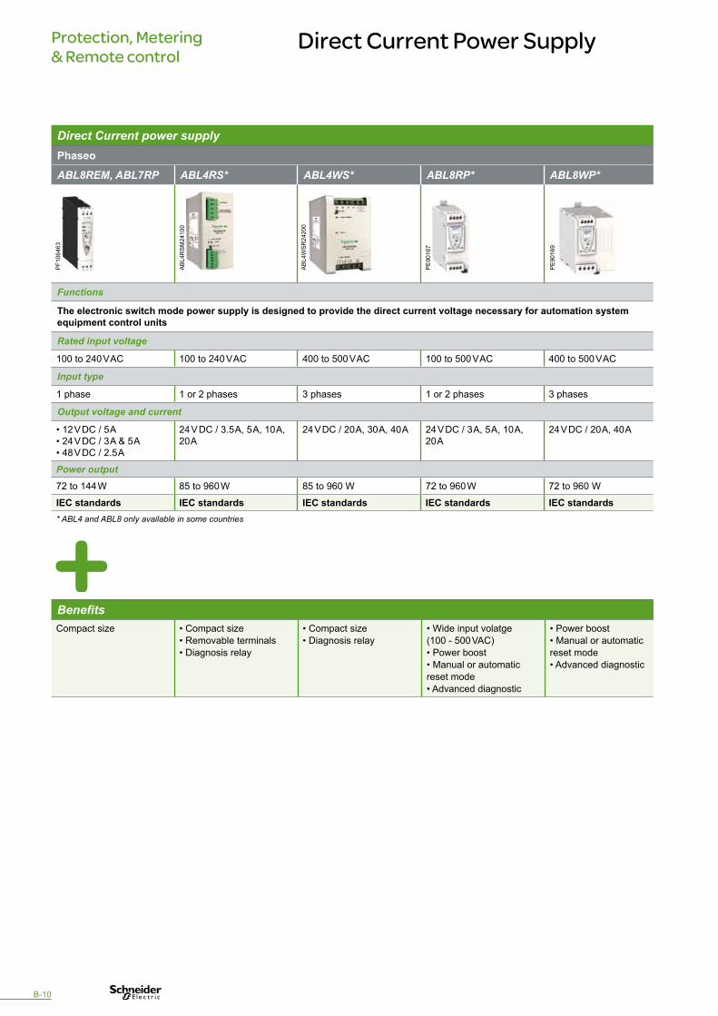
Direct Current power supplyPhaseo
ABL8REM, ABL7RP ABL4RS* ABL4WS* ABL8RP* ABL8WP*
Functions
The electronic switch mode power supply is designed to provide the direct current voltage necessary for automation system equipment control units
Rated input voltage
100 to 240 V AC 100 to 240 V AC 400 to 500 V AC 100 to 500 V AC 400 to 500 V AC
Input type
1 phase 1 or 2 phases 3 phases 1 or 2 phases 3 phases
Output voltage and current
• 12 V DC / 5 A• 24 V DC / 3 A & 5 A• 48 V DC / 2.5 A
24 V DC / 3.5 A, 5 A, 10 A, 20 A
24 V DC / 20 A, 30 A, 40 A 24 V DC / 3 A, 5 A, 10 A, 20 A
24 V DC / 20 A, 40 A
Power output72 to 144 W 85 to 960 W 85 to 960 W 72 to 960 W 72 to 960 W
IEC standards IEC standards IEC standards IEC standards IEC standards* ABL4 and ABL8 only available in some countries
BenefitsCompact size • Compact size
• Removable terminals• Diagnosis relay
• Compact size• Diagnosis relay
• Wide input volatge (100 - 500 VAC)• Power boost• Manual or automatic reset mode• Advanced diagnostic
• Power boost• Manual or automatic reset mode• Advanced diagnostic
PF1
0646
3
AB
L4R
SM
2410
0
AB
L4W
SR
2420
0
PE
9016
7
PE
9016
9
B-10

Protection, Metering & Remote control
Low Voltage relays
Electromechanical plug-in relaysZelio relays
Miniature relays RXM Universal relays RUM
Functions
Designed for the adaptation, amplification, multiplication and processing of information in automated system
Switching voltage
12/250 VAC/DC
Number of contacts
2, 3 or 4 CO 2 or 3 CO
Current
6 - 10 - 12 A 10 A
Mounting
Plugs into socket (DIN rail)
IEC 61984-1
PE
9019
9
PE
9020
0
Benefits• Wide choice of number of contacts (up to 4)• Simplicity of installation and maintenance• Standardisation of relay pin arrangement on its socket.• “Test” button for checking the relay functions, even in a remote enclosure• Clear indication: contact status mechanical indicator and “Relay On” @LED indicator• Suitable input/output currents and switching voltages
B-11

Protection, Metering & Remote control
Low Voltage Control & Signalling
Pushbuttons & SwitchesZB6/XB6 XB7 ZB5/XB5 ZB4/XB4 K1/K2
Functions
Enables operation of the Low Voltage circuits of the Medium Voltage cubicle
Mounting hole (mm)
16 22 16/22
Material
Plastic Metallic Plastic or metallic
Head shape
Composition type
Modular Unibody Modular
Panel fixing with
Plastic nut 3 points metal Plastic nut or 4 screws
Degree of protection
IP 65 IP 65 IP 66 IP 66 IP 40 / IP 65
Rated insulation voltage250 V 250 V 600 V 600 V 690 V
UL/CSA, IEC UL/CSA, IEC UL/CSA, IEC, CCC, GOST
UL/CSA, IEC, CCC, GOST
UL/CSA, IEC
1098
65
PF0
9440
0
1077
56
1030
60
1074
35
1077
47
PF5
6914
1
1074
39
1074
06
1073
95
1074
26
1035
15
1014
49
1074
33
1076
00
1035
02
Benefits• Easy to select and to install• A wide choice of functions• Robustness & mechanical durability• High protection degree• Excellent aesthetics and ergonomics
B-12

Illuminated Pushbuttons, Pilot lights & SwitchesXVL ZB6/XB6 XB7 ZB5/XB5 ZB4/XB4
Functions
Provides status information and enable control of Low Voltage circuits
Mounting hole (mm)
8/10/12 16 22
Material
Plastic Metallic
Head shape
Composition type
Unibody Modular Unibody Modular
Panel fixing with
Plastic nut 3 points metal
Degree of protection
IP 40 / IP 65 IP 65 IP 65 IP 66 IP 66
Rated insulation voltage50 V 250 V 250 V 600 V max 600 V max
UL/CSA, IEC UL/CSA, IEC UL/CSA, IEC UL/CSA, IEC, CCC, GOST
UL/CSA, IEC, CCC, GOST
1074
1710
7416
1074
18
1074
36
PF1
0040
0
PF5
6914
110
7751
1074
32
1074
2911
0030
PF5
6915
0P
F106
192
Benefits• Long life resistance (LED technology)• True colours and excellent brightness• A wide choice of voltages• High protection degree• Easy mounting
B-13

Protection, Metering & Remote control
Low Voltage Control & Signalling
Selector switchesCMA CMV
Functions
CMA uses a single ammeter (by means of Current Transformers) for successive measurement of the currents of a three-phase circuit
CMV uses a single voltmeter for successive measurement of voltages (phase-to-phase and phase-to-neutral) of a three-phase circuit
48 x 48 Flush mounted 48 x 48 Flush mounted
Mechanical switching cycles
2 000 000
Electrical switching cycles
100 000
Max. rated voltage
500 V
Max. rated current
20 A
IEC 60947-3
N 1 2 3
4 3
A
CMA
S1
S2 S1
S2 S1
S24 10 2
3 9
1 3
O
L3-1
L2-3
L1-2
L3-N
L2-N
L1-N
1 2 3 4
230 V
N L
V
L3L2L1N
12 10 6 2
Benefits• AgNi contact ensuring mechanical durability• IP65 on front face
PE
9049
3
PE
9049
4
B-14

Protection, Metering & Remote control
Low Voltage Control & Signalling
Terminal Blocks Cable EndsAB1 VV AB 1RRN AB1 AA DZ5 / AZ5
Functions
Ensures connection of Low Voltage cables or wires • Facilitates the insertion of wires into the terminals and assures the insulation between adjacent connection• Allows the identification of the wires
Technology
Screw clamp technology Spring clamp technology Insulation displacement technology
Insulated cable ends
Connection functions
• Passthrough (2.5 - 240 mm²)• Protective earth• Disconnect type (blade or fuse)• Double deck, multi-pole• Multifunction• Neutral disconnect
• Passthrough (2.5 - 35 mm²)• Protective earth• Disconnect type (blade or fuse)• Double deck, multi-pole
• Passthrough (1 - 2.5 mm²)• Protective earth• Disconnect type (blade or fuse)• Double deck, multi-pole
Three available versions:• Single conductor cable ends• Single conductor markable cable ends• Twin conductor cable ends
Conductor nominal c.s.a. (cross section area)
2.5 mm² to 240 mm² 2.5 mm² to 35 mm² 1 mm² and 2.5 mm² 0.25 mm² to 50 mm²
Number of poles
1 - 1 x 1 / 1 - 2 x 2 2 - 1 x 1 / 3 - 1 x 1
1 - 1 x 1 / 1 - 1 x 2 / 1 - 2 x 22 - 1 x 1 / 2 - 1 x 2 / 3 - 1 x 1
1 - 1 x 1 / 1 - 1 x 2 / 1 - 2 x 22 - 1 x 1
Clip-on mounting on rail type
IEC 60947-7-1, UL, CSA, VDE, ATEX
IEC 60947-7-1, UL, CSA, VDE IEC 60947-7-1, UL, CSA, ATEX NFC 63-023, DIN 46228, UL, CSA
BenefitsRugged and reliable.This technology not only provides quality, safety and availability of equipment but optimizes installation setup and operation with their simple integrated functions
Cost effective (quick and reliable)Spring technology is a maintenance-free connection method assuring separation of mechanical and electrical functions. It also eliminates the need for regular re-tightening
Quick and innovative.Simply cut the wire to the desired length, insert a screwdriver into the wire guide and contact is established when the screwdriver is moved towards the center of the terminal block. This eliminates the need for stripping the wire.
Fast and reliable wiring.Don’t forget the AZ5 and DZ5 ranges of cable ends to simplify wiring and provide optimum electrical continuity between wire and terminal block.
8174
08
PF1
0656
7
1067
11
8174
49_2
8174
49_1
PE
9049
5
8174
14
PF1
0657
26
1066
91
B-15

Substation remote control and monitoring unitsEasergy
T200I Flair 200C
Functions
• Provides switch remote monitoring and control• Option for Automatic Trans-fer System (ATS) using Voltage Presence Information from VD23 (see D-2)
Provides remote access to fault detection and data monitoring of the substation
• Capacity: 1-16 switches• Battery autonomy: 16 h• Fault indicator: phase and earth fault• Uninterruptible power supply: 24 or 48 Vcc
• One or two Fault Indicators:phase and earth fault for all types of neutral arrangement• Integrated functions of measurement and monitoring of the substation and data transmission
Protocols
IEC 870-5-101 and 104, DNP3/DNP3 IP, Modbus/Modbus TCP and various customer owned protocols
Transmission systems
• Ethernet, RS232/485, radio, PSTN, GSM, GPRS• Periodic call management• Concentration of Modbus slave devices• Embedded web server• Local and remote configuration
IEC standards IEC standards
Protection, Metering & Remote control
Substation remote control and monitoring & Fault indicators
PE
9051
3
PE
9044
3
PE
9044
4
PE
9044
5
BenefitsAll-In-One device:- reliability- single configuration and diagnostic tool
• All-In-One device:- reliability- single configuration and diagnostic tool• Opens the door to the most advanced Smart grid monitoring needs
• Easy commissioning • Highly configurable• Long life time• Measurement functions included• Advanced fault detection features
• Configurable fault detection settings• Ten years life time battery
B-16
Fault Passage Indicators (FPI)Easergy
Flair 21D-22D-23DV Flair 219-279
Functions
Provides phase and earth fault local indicationAmmetric FPI, self powered by measurement sensors, integrated in MV switchgear or in wall-mounted box
Ammetric FPI, powered by LV supply and/or battery, wall-mounted installation
Detection
Phase and earth fault
Setting
By dip switches or menu on LCD display
By dip switches
Installation
Embedded in the switchgear Wall mounted
Earthing system
Direct, impedant, compensated, isolated
Supply
Self powered by current sensor (+ Li battery on Flair 22D)
• Flair 279: 230V AC + Li battery• Flair 219: Li battery
Measurement
• Ammeter• Maxmeter
Communication
Dry output contact Dry output contact
IEC standards IEC standards
Protection, Metering & Remote control
Substation power supply
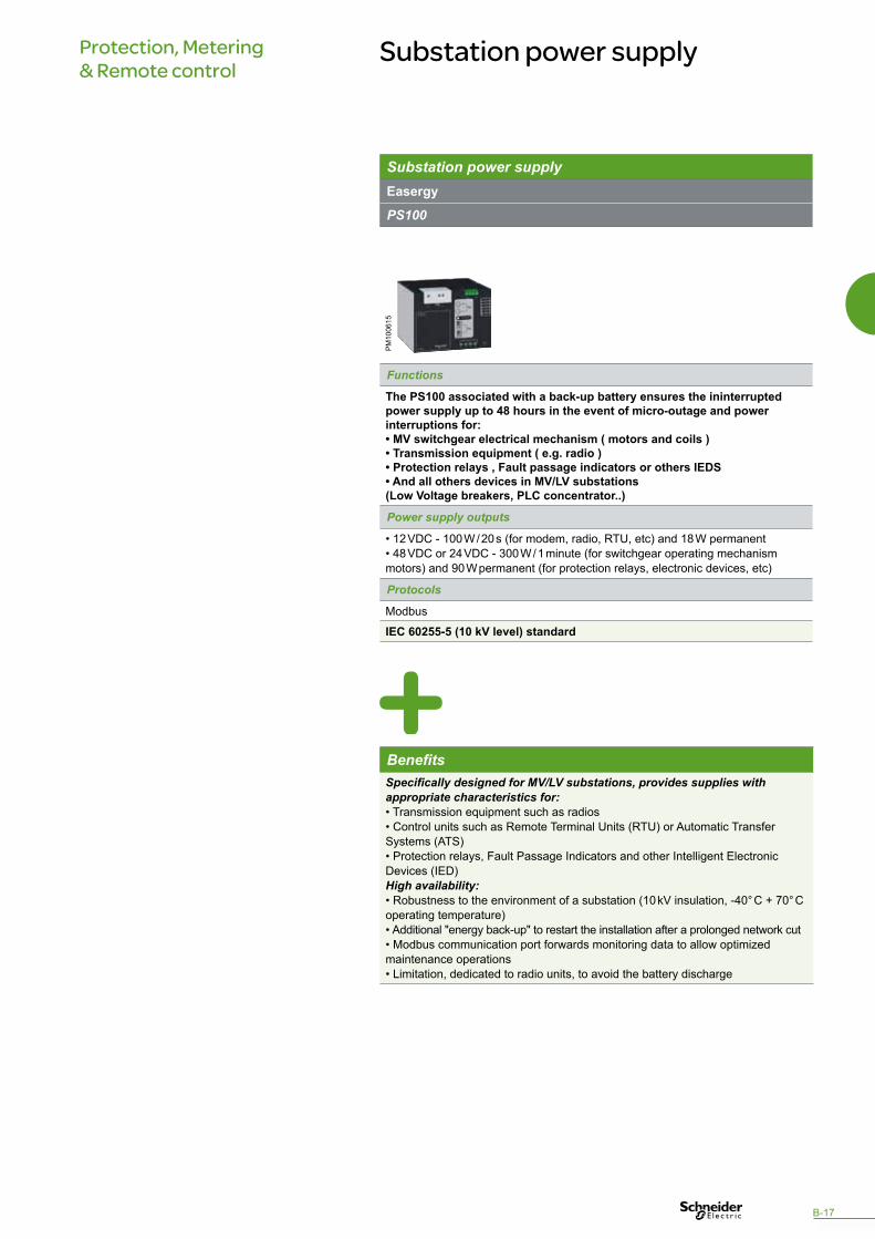
Substation power supplyEasergy
PS100
Functions
The PS100 associated with a back-up battery ensures the ininterrupted power supply up to 48 hours in the event of micro-outage and power interruptions for: • MV switchgear electrical mechanism ( motors and coils ) • Transmission equipment ( e.g. radio ) • Protection relays , Fault passage indicators or others IEDS • And all others devices in MV/LV substations (Low Voltage breakers, PLC concentrator..)
Power supply outputs
• 12 VDC - 100 W / 20 s (for modem, radio, RTU, etc) and 18 W permanent• 48 VDC or 24 VDC - 300 W / 1 minute (for switchgear operating mechanism motors) and 90 W permanent (for protection relays, electronic devices, etc)
Protocols
Modbus
IEC 60255-5 (10 kV level) standard
PM
1006
15
BenefitsSpecifically designed for MV/LV substations, provides supplies with appropriate characteristics for:• Transmission equipment such as radios• Control units such as Remote Terminal Units (RTU) or Automatic Transfer Systems (ATS)• Protection relays, Fault Passage Indicators and other Intelligent Electronic Devices (IED)High availability:• Robustness to the environment of a substation (10 kV insulation, -40° C + 70° C operating temperature)• Additional "energy back-up" to restart the installation after a prolonged network cut• Modbus communication port forwards monitoring data to allow optimized maintenance operations• Limitation, dedicated to radio units, to avoid the battery discharge
B-17

Energy efficiency with Power FactorCorrection
Most utilities have specific policies for billing reactive energy. Price penalties are applied if the active power / apparent power ratio is not within the guidelines.
Power Factor Correction solutions modify and control the reactive power to avoid utility penalties, and reduce overall kVA demand. These solutions result in lowering utility power bills by 5 to 10%.
C-0
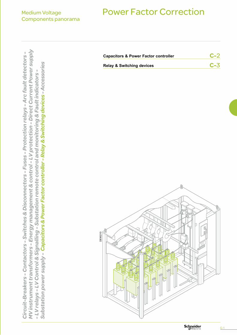
Power Factor Correction
Capacitors & Power Factor controller
Relay & Switching devices
Medium VoltageComponents panorama
Circ
uit-
Brea
kers
- Co
ntac
tors
- Sw
itche
s & D
isco
nnec
tors
- Fu
ses -
Pro
tect
ion
rela
ys -
Arc
faul
t det
ecto
rs -
MV
inst
rum
ent t
rans
form
ers -
Ene
rgy
man
agem
ent &
con
trol
- LV
pro
tect
ion
- Dire
ct C
urre
nt P
ower
supp
ly
- LV
rela
ys -
LV C
ontr
ol &
Sig
nalli
ng -
Subs
tatio
n re
mot
e co
ntro
l and
mon
itorin
g &
Fau
lt in
dica
tors
-
Subs
tatio
n po
wer
supp
ly -
Cap
acito
rs &
Pow
er F
acto
r con
trol
ler -
Rel
ay &
Sw
itchi
ng d
evic
es -
Acce
ssor
ies
DE
9021
0
C-1
C-2C-3
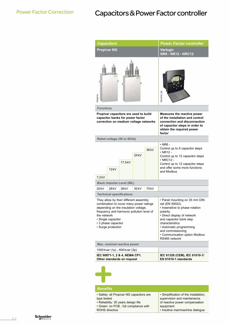
Power Factor Correction Capacitors & Power Factor controller
Capacitors Power Factor controllerPropivar NG Varlogic
NR6 - NR12 - NRC12
Functions
Propivar capacitors are used to build capacitor banks for power factor correction on medium voltage networks
Measures the reactive power of the installation and controlconnection and disconnectionof capacitor steps in order toobtain the required power factor
Rated voltage (50 or 60 Hz)
• NR6 - Control up to 6 capacitor steps• NR12 - Control up to 12 capacitor steps• NRC12 - Control up to 12 capacitor stepsand offer some more functionsand Modbus
36 kV
24 kV
17,5 kV
12 kV
7,2 kV
Basic Impulse Level (BIL)
20 kV 28 kV 38 kV 50 kV 70 kV
Technical specifications
They allow by their different assembly combination to cover many power ratings depending on the insulation voltage, frequency and harmonic pollution level of the network• Single capacitor• 3 phase capacitor• Surge protection
• Panel mounting on 35 mm DINrail (EN 50022).• Insensitive to phase rotationpolarity.• Direct display of networkand capacitor bank stepcharacteristics• Automatic programmingand commissioning• Communication option Modbus RS485 network
Max. nominal reactive power
1000 kvar (1p) - 600 kvar (3p)
IEC 60871-1, 2 & 4, NEMA CP1.Other standards on request
IEC 61326 (CEM), IEC 61010-1/EN 61010-1 standards
PE
9051
6
PB
1003
2_S
E
Benefits• Safety: all Propivar NG capacitors are type tested• Reliability: 30 years design life• Green: no PCB ; full compliance with ROHS directive
• Simplification of the installation,supervision and maintenanceof reactive power compensationequipment• Intuitive man/machine dialogue
C-2

Power Factor CorrectionCapacitors & Power Factor controller Relay & Switching devices
Benefits• Compliance with RoHS European directive • Low Energy consumption
C-3
Protection relaysSepam series C86
Fonction
Protection relay dedicated to capacitor application
Self power / Auxiliary supply
Auxiliary supply
Protection
• Current (1 or 5 A or LPCT)• Voltage
- Phase & Earth basic- Directional- Synchro-check- Differential
Display
• Standard UMI• Remote UM• Mimic based UMI
Other characteristics
Removable S/W cartridge
Input / Output (up to)
42 / 23
I/O terminals
• Screw type• Ring lug
Temperature sensor (up to)
8 to 16
Communication protocol
• Modbus RTU• IEC 60870-5-103• DNP3• Modbus TCP/IP• IEC 61850 Customized GOOSE• RSTP*
Logic equations
Control logic by ladder diagram
Safety characteristics
IEC 61508 - SIL2
IEC standards* Ethernet high availability communication
Switching devices adapted to capacitor applicationsCircuit - Breakers• SF1 & SF2• HVX
Contactors• Rollarc• CBX (specific version)• CPX (specific version up to 3.6 kV)
PE
9051
2
D-0

AccessoriesMedium VoltageComponents panorama
DE
9020
6_3
Circ
uit-
Brea
kers
- Co
ntac
tors
- Sw
itche
s & D
isco
nnec
tors
- Fu
ses -
Pro
tect
ion
rela
ys -
Arc
faul
t det
ecto
rs -
MV
inst
rum
ent t
rans
form
ers -
Ene
rgy
man
agem
ent &
con
trol
- LV
pro
tect
ion
- Dire
ct C
urre
nt P
ower
supp
ly
- LV
rela
ys -
LV C
ontr
ol &
Sig
nalli
ng -
Subs
tatio
n re
mot
e co
ntro
l and
mon
itorin
g &
Fau
lt in
dica
tors
-
Subs
tatio
n po
wer
supp
ly -
Capa
cito
rs &
Pow
er F
acto
r con
trol
ler -
Rel
ay &
Sw
itchi
ng d
evic
es -
Acce
ssor
ies
D-1

Accessories
AccessoriesSepam 100MI VPIS V2
and phase concordance unitVD23 Insulating holder w or
w/o capacitive divider
Functions
Module with animated mimic diagram and selector switch / pushbutton for local or remote control, showing the cubicle single line diagram with devices symbolized
• Self-powered Voltage Presence Indicating System• Including voltage output version (VPIS-VO) for connection to a VD23 Voltage presence relay• Needs Phase Concordance Unit for Phase concordance checking
• Indicates presence or absence of voltage through 1 or 2 relays• For MV networks from 3 kV to 36 kV• Associated with VPIS-VO
• Without capacitive divider: provides mechanical support and insulation through their rigid fin arrangement; used to support busbars and cable ends• With capacitive divider:provides mechanical support and insulation. The embedded capacitors in this insulating holder provide voltage output to indicate the voltage presence, up to 24 kV
Technical specifications
• Available in 14 standards types• 21-pin connector on the back for the connection of - supply voltage-device position indication output-circuit breaker control (open/close and disconnect) outputs.• Power supply: 24 to 127V AC/DC
• Connectors on the front panel allowing to use a Phase Concordance Unit • Light indication using LEDs• Made in 2 parts: surge protection part, always connected and Voltage presence indication part, replaceable for maintenance
• Self-adapted to network Voltage• Displays the voltage in % of nominal• Output contacts behaviour configurable according to various combinations of phase and unbalance voltage status• DIN format• Allows to address various applications: - Automatic transfer systems- Alarms on voltage loss- Automation on voltage loss- Earth locking on voltage presence- Alarms on voltage presence
• Height: 175 mm• Capacitive divider: ISO 35 pf
Reference numbers
Each module is suited to a particular indication and local control application chosen according to:• Cubicle single-line diagram• Devices whose positions are to be indicated• Required local control functions
• 4 versions according to voltage ranges:- VPI624x3 (2 kV-4 kV)- VPI624x4 (3 kV-6,3 kV)- VPI624x7 (9 kV-17 kV)- VPI624x8 (13 kV-25 kV)with 2 ref. for each version: - x=0 for VPIS- x=1 for VPIS-VO• Phase concordance unit: VPI62421
• Voltage presence relay (VD23): ref. EMS58421• Combined voltage presence relay + Fault Passage Indicator (Flair 23DV): ref. EMS58353
• 3 isolateurs standards :- 17.5 kV ref. 59431 - 24 kV ref. AAA10075• 3 isolateurs avec diviseurs capacitifs : - 17.5 kV ref. 59430 - 24 kV ref. AAA10074
IEC standards IEC 61958 IEC standards IEC standards
PE
9050
0
PE
9051
4
PE
9051
5
PE
5683
0
Benefits• Includes all the animated mimic elements for viewing, breaking and disconnection devices status• Compact size and easy installation• Reduced cabling• Stand-alone or with Sepam
High reliability thanks to:• Harsh environment design• LED indication: extended life time
• Fits all MV network neutral systems• Compact (DIN format)• Output contact behaviour highly configurable according to configuration needs
• Dielectric withstand• Mechanical robustness
D-2
PE
5814
1

AccessoriesAnti-condensation Heating element
Insulation busbar cover
High resistance plastic window
Cubicle compartment handle
Extraction table
Functions
Heating the inside of the cubicle when the ambient temperature is too low
Set of 3 insulating covers which enables improved dielectric withstand at the busbars connections in the cubicle
Located on the panel or the door, allows you to see inside a cubicle
Enables the front panel door of the cubicle to be closed.
Enables the circuit-breaker to be taken out of the cubicle and handled during maintenance operations or cubicle manufacturing
Technical specifications
• 220 V AC• 150 W• Length: 432 mm • Supplied with its support without thermostat
For 1 to 4 busbars (100 m x 800 mm each)
• 3 mm thick transparent Polycarbonate window• Dimensions:138 mm x 85 mm
• Material: Zamak• A version with key is available
• Height adjustment up to 250 mm• A latching device is provided between the extraction table and the cradle
Reference numbers
59280 59420 59105 • 59270 (handle)• 59271 (handle with key)
Available for respective circuit-breakers ranges.• For Evolis:- 59130 (full extraction table)- 59129 (top tray of the table + full device drawings for local manufacturing)• For other circuit-breakers, please contact us
DE
9020
7
DE
9021
3
DE
9021
4
DE
9021
6
DE
5692
7
BenefitsAvoid condensation in the cubicle
Can be adjusted according to number of busbars
Internal arc withstand up to 31.5 kA
Robustness Possibility to manufacture locally the table support frame
D-3
All useful documents are available throughwww.schneider-electric.com
Components for Medium Voltage cubicles
Schneider Electric Industries SAS35, rue Joseph MonierCS 30323F-92505 Rueil-Malmaison cedex (France)Tel.: +33(0)1 41 29 70 00RCS Nanterre 954 503 439Capital social 896 313 776 Ewww.schneider-electric.com
NRJED111211EN
As standards, specifications and designs change from time to time, please ask for confirmationof the information given in this publication.
Published by: Schneider ElectricProduced by: SYNTHESE ECA
09/2011 AR
T. 8
3876
5 - ©
2011
- S
chne
ider
Ele
ctric
Indu
strie
s S
AS
- A
ll rig
hts
rese
rved
.
This document has beenprinted on ecological paper.
“The widest range of components to meet all your requirements”
Panorama for PanelBuilders