Component Carriers and Housings - Invalid Request
20
292 Component Carriers and Housings
Transcript of Component Carriers and Housings - Invalid Request
292
Component Carriers and Housings
293
Component Carriers and Housings
Ho
usin
gs
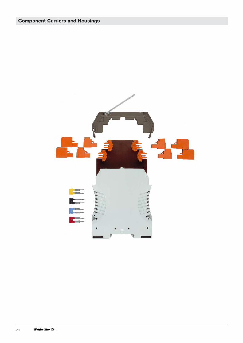
Weidmüller DK 4 and DKT 4 terminals
are suitable for the installation of electroniccomponents with a maximum diameter orwidth of 4.5 mm. Four independent clamp-ing yoke screw connections are available.A snap-on frame expands the installationspace in the DK4 by 6 mm respectively.Depending on type, these modular termi-nals are suitable for mounting on TS 32,TS 35 x 7.5 or TS 35 x 15 mounting railsaccording to European standards EN 50035 and EN 50 022.
Weidmüller WDK 2.5 terminals
are suitable for the installation of electricalcomponents with a maximum width of 4mm. As many as four independent clamp-ing yoke screw connections or 4 6.3 x 0.8tab connections are available. These termi-nals are suitable for mounting on TS 35 x7.5 or TS 35 x 15 mounting rails.
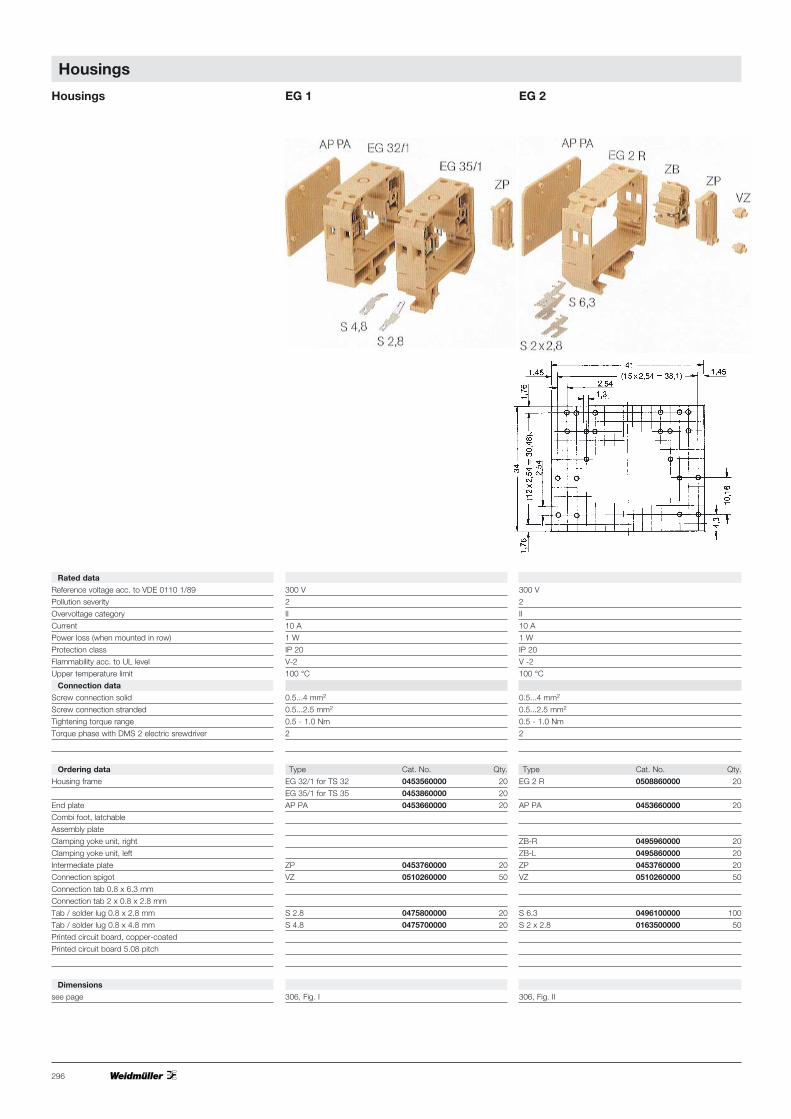
Weidmüller EG 1 housings
offer 4 screw connections and, as acces-sories, up to 4 0.8 x 4.8 mm solder/tabconnections on a width of 18 mm. Thescrew clamp busbar ends with a solderring inside the housing. Two end platesseal the module. Depending on type, themodules are mounted on TS 32, TS 35 x7.5 or TS 35 x 15 mounting rails.
Weidmüller EG 2 housings
The external shape of these housings cor-responds to Type EG 1. Four screw con-nections or up to 8 0.8 x 6.6 mm/0.8 x2.8 mm tab connectors are connectedwith a printed circuit board in the housing.They can be mounted on TS 32, TS 35 x7.5 or TS 35 x 15 mounting rails.
Weidmüller EG 3 housings
provides 6 screw connections or 12 0.8 x 6.3 mm/0.8 x 2.8 mm tab connec-tions on a width of 22.5 mm. As an acces-sory, Weidmüller offers a shaped printedcircuit board with a 2.54 mm hole grid or fully copper-coated. The engagablecombination foot allows the terminal to be mounted on TS 32, TS 35 x 7.5 or TS 35 x 15 mounting rails. The MPL mounting plate is used to mountthe housing directly (without mounting rail).Due to the sliding foot construction, theEG 3 can be turned through 180° in alltypes of assembly (e.g. exchanging inputand output).
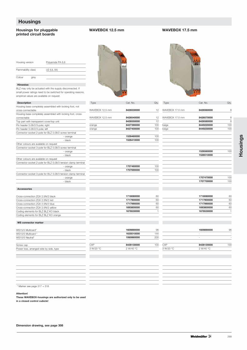
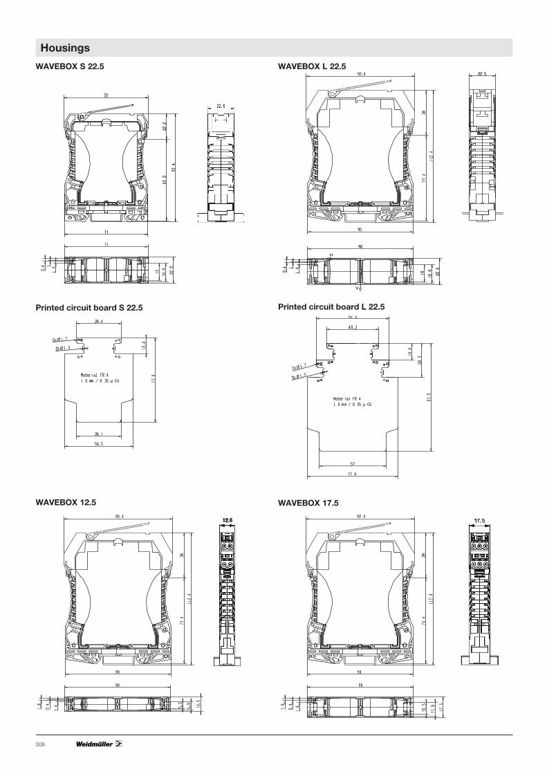
Weidmüller housings type WAVEBOX
It is essential to provide fit-for-use housingsfor modern electronic components. Settingand control functions must be easily car-ried out and technical requirements withrespect to heat dissipation and EMV prop-erties should be supported.An ideal design saves space and wiringcosts in the switchgear cabinet.In addition, ergonomics and design arebecoming increasingly important for high-quality electronic products.These are the criteria that led to the devel-opment of WAVEBOX. Simplified produc-tion methods (shaft soldering, SMD) ensurecost-savings for the customer. The WAVEBOX is characterised by:• Optimum width for any application
(12.5 mm, 17.5 mm, 22.5 mm)• Large component assembly surface;
SMDs can be mounted on the solderside
• UL94 flammability class V2• No tools required for assembly• Plug-in printed circuit board• Plug-in cross-connection via ZQV 2.5 N• Hinged, transparent cover• BLZ 5.08 screw/plug and socket con-
nector• BLFZ 5.08 optional tension clamp/plug
and socket connector• Marking option with WS tags• Mounts onto TS 35Weidmüller individual parts for RS 70locking socketlatch together to form units from 20 mm inwidth. Any desired intermediate parts orfeet can be connected between two sidepieces (locking feet) at intervals of 5 mm. Inthis way, a carrier module is constructedfor PCB, on which various componentscan be soldered. The assembly snaps ontoTS 32, TS 35 x 7.5 or TS 35 x 15 mount-ing rails.
The Weidmüller RSX custom circuitmoduleis a largely prefabricated unit wich acceptsup to 5 components such as resistors,diodes, varistors or capacitors via solderingterminals. The components are connectedvia screw clamps or tab connections. Thismodule is also suitable for mounting on TS32, TS 35 x 7.5 or TS 35 x 15 mountingrails.Weidmüller locking socket profiles
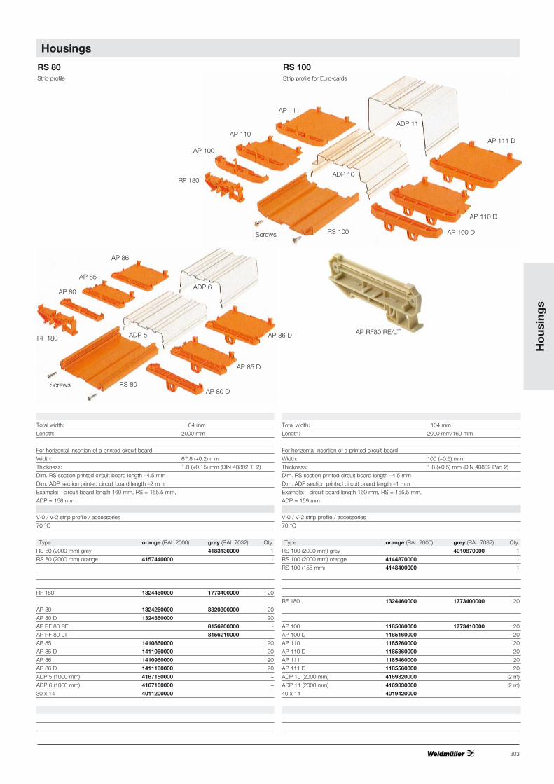
The RS 45, RS 80 and RS 100 profiles areavailable as 2 m long strips. The extrudedprofiles can be easily cut to any length witha saw. In this way, a carrier module is con-structed for a printed circuit board onwhich various components can be solder-ed. Locking feet can be slid into these pro-files for mounting on TS 32, TS 35 x 7.5 or TS 35 x 15 mounting rails. Thesliding foot construction of the RS 80 alsoallows the fixing foot be turned through 180°.
Weidmüller EG 4 housing
as type EG 3, offers the same width of22.5 mm. However, the greater installationdepth (75 mm) and height (109 mm) allowthe installation of more complex circuitconfigurations. The built-in installation canbe connected via 6 screw connections.The snap-on combination foot allows theterminal to be mounted on TS 32, TS 35 x7.5 or TS 35 x 15 mounting rails. Due tothe sliding foot construction, the EG 4 canbe slid forwards or backwards on thelocking foot, and can be turned through180° (e.g. exchanging of input and out-put).
Weidmüller EG 5 housings
correspond to type EG 4. The EG 5 has12 screw connections, which can be wiredwith solder lugs inside the housing. Thesnap-on combination foot allows the ter-minal to be mounted on TS 32, TS 35 x7.5 or TS 35 x 15 mounting rails. Due tothe sliding foot construction, the EG 4 canbe slid 6 mm forwards or backwards onthe engaging foot and can be turnedthrough 180° (e.g. exchanging input andoutput).
Weidmüller EG 6 housings
have a bus-suitable contact carrier. Thebus connection is created by directlymounting several housings in a row. 32connections are available on both sides ofthe housing as crimp connector blockcontacts. The housing accepts printed cir-cuit boards with dimensions of 100 x120mm. The printed circuit board is adaptedwith a VG 64 DIN strip. The front panel isscrewed onto the circuit board similar tothe 19" technology. The locking footallows easy mounting onto the TS 35mounting rail.
Weidmüller SEG/U housing
enable the plug-in module assembly of a70 x 52 x 1 mm printed circuit board. Thecircuit board is attached to the accessorycover plate via snap-in hooks. The housingcontains a 13-pole socket block for instal-lation of the module; 6 screw connectionsare available for connection. The permissi-ble power loss in the housing during con-tinuous operation of terminals in rowsamounts to 1.5W, depending on the sur-face temperature of the soldered compo-nents. The snap-on combination footallows the housings to be mounted on TS32, TS 35 x 7.5 or TS 35 x 15 mountingrails.

6 mm
9 mm
0.5…4 mm2
0.5…4 mm2
AWG 22…12
0.5-1.0 Nm
1
4 mm2
380 V~
10 A
0.5 W
DK 4 PA DK 4 PA
1537960000 1115460000
DK 4/35 PA DK 4/35 PA
8203490000 1115560000
DK 4 RA DK 4 RA
0690960000 0690960000
DK 4 RA/35 DK 4 RA/35
0691060000 0691060000
Type Cat. No. Qty.
TS 32 0122800000 2 m
TS 35 x 7.5 0383400000 2 m
TS 35 x 15 0498000000 2 m
EWK 1 (8.5) 0206160000 50
EW 35 (8.5) 0383560000 50
AP PA (1.5) 0359260000 20
TSch 4 0363360000 100
StB 8.5 0215700000 50
PS (ø 2.3) 0180400000 20
Q 2 0336400000 50
Q 3 0336500000 50
Q 4 0336600000 50
Q 10 0368600000 20
VL 2 0446700000 –
VH 10 0446600000 100
BS M 2.5 x 14 0266800000 100
AD 4 0303400000 50
BSK M 2.5 x 18 0303300000 100
QB 2* 0482700000 100
QB 3* 0482800000 50
QB 4* 0482900000 50
QB 75 blank* 0526400000 10
Insulation profile 0526700000 –
* Accessories see terminals catalogue
294
Dimensions
Terminal width
(+fitting tolerance 0.2)
Insulating stripping length
Connection data
Screw connection, solid
Screw connection, stranded
Conductor cross-section
Tightening torque range
Torque phase with
DMS 2 electric screwdriver
Rated data acc. to VDE
Rated cross-section
Rated voltage
Rated current
Power loss
Connection diagram
Ordering data
Terminal
for TS 32 Y Type
Cat. No.
for TS 35 W Type
Cat. No.
Matching contour frame
for TS 32 Y Type
Cat. No.
for TS 35 W Type
Cat. No.
Accessories
Mounting rail (2 m lenghts)
End bracket for TS 32
(thickness mm) for TS 35
End plate (thickness mm)
Partition
Socket for test plug
Test plug (pin diameter)
Cross-connection 2-pole
(preassembled) 3-pole
4-pole
10-pole
Switchable cross-connection bracket
Connection sleeve
Fixing screw
Cover plate (4 terminals)
Fixing screw (plastic)
Cross connection bridge
Terminals DK 4 DKT 4
6 mm
9 mm
0.5…4 mm2
0.5…4 mm2
AWG 22…17
0.5 - 1.0 Nm
1
4 mm2
380 V~
10 A
0.5 W
DKT 4 PA DKT 4 PA
1686940000 1115660000
DKT 4 /35PA DKT 4/35 PA
0687460000 1115760000
Type Cat. No. Qty.
TS 32 0122800000 2 m
TS 35 x 7.5 0383400000 2 m
TS 35 x 15 0498000000 2 m
EWK 1 (8.5) 0206160000 50
EW 35 (8.5) 0383560000 50
AP PA (1.5) 0687560000 20
TSch 4 0363360000 100
QB 2* 0482700000 100
QB 3* 0482800000 50
QB 4* 0482900000 50
QB 75 blank* 0526400000 10
Insulation profile 0526700000 –
Housings

295
Ho
usin
gs
Dimensions
Terminal width
(+fitting tolerance 0.2)
Insulating stripping length
Connection data
Screw connection, solid
Screw connection, stranded
Conductor cross-section
Tightening torque range
Torque phase with
DMS 2 electric screwdriver
Rated data acc. to VDE
Rated cross-section
Rated voltage
Rated current
Power loss
Connection diagram
Ordering data
Terminal
for TS 32 Y Type
Cat. No.
for TS 35 W Type
Cat. No.
Matching contour frame
for TS 32 Y Type
Cat. No.
for TS 35 W Type
Cat. No.
Accessories
Mounting rail (2 m lenghts)
End bracket
(thickness mm) for TS 35
End plate (thickness mm)
Cross-connection 2-pole
(preassembled) 3-pole
4-pole
10-pole
Terminals WDK 2.5 WDK 2.5 F WDK 2.5 FF
5 mm 5 mm
10 mm 10 mm
0.5…4 mm2 0.5…4 mm2
0.5…2.5 mm2 0.5…2.5 mm2
AWG 26…4 AWG 26…4
0.4 - 0.7 Nm
1
2.5 mm2
380 V~
26 A
0.5 W
WDK 2.5 WDK 2.5
1023200000 1023100000
WZR WDK 2.5
1074000000
Type Cat. No. Qty.
TS 35 x 7.5 0383400000 2m
slotted 0514500000 2m
TS 35 x 15 0498000000 2m
EW 35 (8.5) 0383560000 50
WAP 1059100000100
WQV 2.5 1053660000 50
WQV 2.5 1053760000 50
WQV 2.5 1053860000 50
WQV 2.5 1054460000 50
5 mm
10 mm
0.5…4 mm2
0.5…2.5 mm2
AWG 26…4
0.4 - 0.7 Nm
1
2.5 mm2
380 V~
12 A (2 x 6 A)
0.5 W
WDK 2.5 F
1021600000
WZR WDK 2.5
1074000000
Type Cat. No. Qty.
TS 35 x 7.5 0383400000 2m
slotted 0514500000 2m
TS 35 x 15 0498000000 2m
EW 35 (8.5) 0383560000 50
WAP 1059100000100
WQV 2.5 1053660000 50
WQV 2.5 1053760000 50
WQV 2.5 1053860000 50
WQV 2.5 1054460000 50
5 mm
–
1 mm2
380 V~
12 A (2 x 6 A)
0.5 W
WDK 2.5 FF
1021700000
WZR WDK 2.5
1074000000
Type Cat. No. Qty.
TS 35 x 7.5 0383400000 2m
slotted 0514500000 2m
TS 35 x 15 0498000000 2m
EW 35 (8.5) 0383560000 50
WAP 1059100000100
WQV 2.5 1053660000 50
WQV 2.5 1053760000 50
WQV 2.5 1053860000 50
WQV 2.5 1054460000 50
Housings
296
Housings EG 1 EG 2
Rated data
Reference voltage acc. to VDE 0110 1/89
Pollution severity
Overvoltage category
Current
Power loss (when mounted in row)
Protection class
Flammability acc. to UL level
Upper temperature limit
Connection data
Screw connection solid
Screw connection stranded
Tightening torque range
Torque phase with DMS 2 electric srewdriver
Ordering data
Housing frame
End plate
Combi foot, latchable
Assembly plate
Clamping yoke unit, right
Clamping yoke unit, left
Intermediate plate
Connection spigot
Connection tab 0.8 x 6.3 mm
Connection tab 2 x 0.8 x 2.8 mm
Tab / solder lug 0.8 x 2.8 mm
Tab / solder lug 0.8 x 4.8 mm
Printed circuit board, copper-coated
Printed circuit board 5.08 pitch
Dimensions
see page
300 V
2
II
10 A
1 W
IP 20
V-2
100 °C
0.5...4 mm2
0.5...2.5 mm2
0.5 - 1.0 Nm
2
Type Cat. No. Qty.
EG 32/1 for TS 32 0453560000 20
EG 35/1 for TS 35 0453860000 20
AP PA 0453660000 20
ZP 0453760000 20
VZ 0510260000 50
S 2.8 0475800000 20
S 4.8 0475700000 20
306, Fig. I
300 V
2
II
10 A
1 W
IP 20
V -2
100 °C
0.5...4 mm2
0.5...2.5 mm2
0.5 - 1.0 Nm
2
Type Cat. No. Qty.
EG 2 R 0508860000 20
AP PA 0453660000 20
ZB-R 0495960000 20
ZB-L 0495860000 20
ZP 0453760000 20
VZ 0510260000 50
S 6.3 0496100000 100
S 2 x 2.8 0163500000 50
306, Fig. II
Housings

297
EG 3 EG 4 EG 5
300 V
2
II
10 A
1.5 W
IP 20
V - 2
100 °C
0.5...4 mm2
0.5...2.5 mm2
0.4 - 0.8 Nm
1
Type Cat. No. Qty.
EG 3 R 0163960000 15
AP PA 0133760000 20
RKF 0163860000 20
MPL 0158560000 50
ZBE 0138360000 50
ZBE 0138360000 50
VZ 0510260000 50
S 6.3 0496100000 100
S 2 x 2.8 0163500000 50
LP-CU 0167300000 –
LP-LR 0167400000 –
307, Fig. V
300 V
2
III
10 A
1.6 W
IP 20
V - 2
100 °C
0.5...4 mm2
0.5...2.5 mm2
0.4 - 0.8 Nm
1
Type Cat. No. Qty.
EG 4 R 1116560000 –
AP PA 1116060000 20
RKF 1116260000 20
MPL 1116360000 50
ZBE 0138360000 50
ZBE 0138360000 50
VZ 0510260000 50
ZP 0453760000 –
307, Fig. VI
300 V
2
III
1 A
1.6 W
IP 20
V - 2
100 °C
0.5...4 mm2
0.5...2.5 mm2
0.5 - 0.8 Nm
1
Type Cat. No. Qty.
EG 5 R 1116860000 –
AP PA 1116160000 20
RKF 1116260000 20
MPL 1116360000 50
ZBE 0138360000 50
ZBE 0138360000 50
VZ 0510260000 50
ZP 0453760000 –
307, Fig. VII
Ho
usin
gs
Housings

298
Housing version Polyamide PA 6.6
Flammability class U2 (UL 94)
Colour grey
Notes:
BLZ may only be actuated with the supply disconnected. If
small power ratings need to be switched for operating reasons,
empirical values are available on request.
Description
Housing base completely assembled with locking foot, not
cross-connectable
Housing base completely assembled with locking foot, cross-
connectable
Top part with transparent cover/top unit
Pin header 5.08/3-pole orange; right
Pin header 5.08/3-pole orange; left
Connector socket 2-pole for BLZ 5.08/2 screw terminal
- orange
- black
Other colours are available on request
Connector socket 3-pole for BLZ 5.08/3 terminal
- orange
- black
Other colours are available on request
Connector socket 2-pole for BLZ 5.08/3 tension clamp terminal
- orange
- black
Connector socket 3-pole for BLZ 5.08/3 tension clamp terminal
- orange
- black
Accessories
Cross-connection ZQV 2.5N/2 black
Cross-connection ZQV 2.5N/2 red
Cross-connection ZQV 2.5N/2 blue
Cross-connection ZQV 2.5N/2 yellow
Coding elements for BLZ BLZ KO black
Coding elements for BLZ BLZ KO orange
WS connector marker
WS15/5 Multicard*
WS10/5 Multicard *
WS10/5 Neutral*
Screw cap
Power loss, arranged side by side, type
Ordering example WAVEBOX S 22.5
Housing base completely assembled with locking foot, not
cross-connectable
Top part with transparent cover/top unit
Pin header 5,08/3-pole orange; right
Pin header 5.08/3-pole orange; left
Connector socket 3-pole for BLZ 5.08/3 screw terminal, orange
* Marker see page 317 + 318
Attention!
These WAVEBOX-housings are authorized only to be used
in a closed control cubicle!
Type Cat. No. Qty.
WAVEBOX S 22.5 8426440000 10
WAVEBOX S 22.5 QV 8426450000 10
Head 8426460000 10
Pin header 8426620000 10
Pin header 8426630000 10
Connector socket 1526560000 100
Connector socket 1526510000 100
Connector socket 1707470000 100
Connector socket 1707700000 100
ZQV 2.5N/2 black 1718080000 60
ZQV 2.5N/2 red 1717900000 60
ZQV 2.5N/2 blue 1717990000 60
ZQV 2.5N/2 yellow 1693800000 60
Coding element 1545710000 100
Coding element 1573010000 100
- -
- -
2.2 W/40 °C
Type Cat. No.
8426440000 1x
8426460000 1x
8426620000 1x
8426630000 1x
1526560000 2x
Type Cat. No. Qty.
WAVEBOX L 22.5 8426470000 10
WAVEBOX L 22.5 QV 8426480000 10
8426490000 10
8426620000 10
8426630000 10
1526560000 100
1526510000 100
1707470000 100
1707700000 100
1718080000 60
1717900000 60
1717990000 60
1693800000 60
1545710000 100
1573010000 100
- -
- -
CAP 8428120000 -
3 W/20 °C 2.2 W/40 °C
Dimension drawing, see page 308
WAVEBOX S 22.5 WAVEBOX L 22.5Housings for pluggable printed circuit boards
Housings
299
Ho
usin
gs
Type Cat. No. Qty.
WAVEBOX 12.5 mm 8426530000 12
WAVEBOX 12.5 mm 8426540000 12
8426550000 12
orange 8427390000 100
orange 8427400000 100
1526460000 100
1526410000 100
1707460000 100
1707690000 100
1718080000 60
1717900000 60
1717990000 60
1693800000 60
1678530000 1
1609890000 96
1635010000 144
1060860000 200
CAP 8428130000 100
3 W/20 °C 2 W/40 °C
Type Cat. No. Qty.
WAVEBOX 17.5 mm 8426560000 8
WAVEBOX 17.5 mm 8426570000 8
8426580000 8
beige 8449220000 100
beige 8449230000 100
1526560000 100
1526510000
1707470000 100
1707700000 100
1718080000 60
1717900000 60
1717990000 60
1693800000 60
1678530000 1
1609890000 96
- -
- -
CAP 8428120000 100
3 W/20 °C 2 W/40 °C
Dimension drawing, see page 308
WAVEBOX 12.5 mm WAVEBOX 17.5 mm
Housing version Polyamide PA 6.6
Flammability class U2 (UL 94)
Colour grey
Hinweise:
BLZ may only be actuated with the supply disconnected. If
small power ratings need to be switched for operating reasons,
empirical values are available on request.
Description
Housing base completely assembled with locking foot, not
cross-connectable
Housing base completely assembled with locking foot, cross-
connectable
Top part with transparent cover/top unit
Pin header 5.08/2/3-pole; right
Pin header 5.08/2/3-pole; left
Connector socket 2-pole for BLZ 5.08/2 screw terminal
- orange
- black
Other colours are available on request
Connector socket 3-pole for BLZ 5.08/3 screw terminal
- orange
- black
Other colours are available on request
Connector socket 2-pole for BLZ 5.08/3 tension clamp terminal
- orange
- black
Connector socket 3-pole for BLZ 5.08/3 tension clamp terminal
- orange
- black
Accessories
Cross-connection ZQV 2.5N/2 black
Cross-connection ZQV 2.5N/2 red
Cross-connection ZQV 2.5N/2 blue
Cross-connection ZQV 2.5N/2 yellow
Coding elements for BLZ BLZ KO black
Coding elements for BLZ BLZ KO orange
WS connector marker
WS15/5 Multicard*
WS10/5 Multicard *
WS10/5 Neutral*
Screw cap
Power loss, arranged side by side, type
* Marker see page 317 + 318
Attention!
These WAVEBOX-housings are authorized only to be used
in a closed control cubicle!
Housings for pluggable printed circuit boards
Housings

300
Housings SEG-U/LPU EG 6
32 V nach VDE 0110/1.89
2
III
1 A/δU 50 0C
12 mΩ
100 x 120 x 1.8 mm
IP 00
V - 2
100 °C
Type Cat. No.
EG 6 (incl. front plate) 8095840000
307
50 V
2
III
1 A
1.5 W
IP 20
V -2
100 °C
0.5...4 mm2
0.5...2.5 mm2
0.5 Nm
1
Type Cat. No. Qty.
Housing SEG/U 8007870000 –
Cover plate 8066100000 –
307
Rated data
Reference voltage acc. to VDE 0110 1/89
Pollution severity
Overvoltage category
Current
Current-carrying capacity of bus contacts
Volume resistance of bus contacts
Printed circuit board dimensions
Power loss (when mounted in row)
Protection class
Flammability acc. to UL level
Upper temperature limit
Connection data
Screw connection solid
Screw connection stranded
Tightening torque range
Torque phase with electric screwdriver DMS 2
Ordering data
Housing frame
End plate
Combi foot, latchable
Assembly plate
Clamping yoke unit, right
Clamping yoke unit, left
Intermediate plate
Connection spigot
Connection tab 0.8 x 6.3 mm
Connection tab 2 x 0.8 x 2.8 mm
Tab / solder lug 0.8 x 2.8 mm
Tab / solder lug 0.8 x 4.8 mm
Printed circuit board, copper-coated
Printed circuit board 2.54 pitch
Dimensions
See page
Housings
301
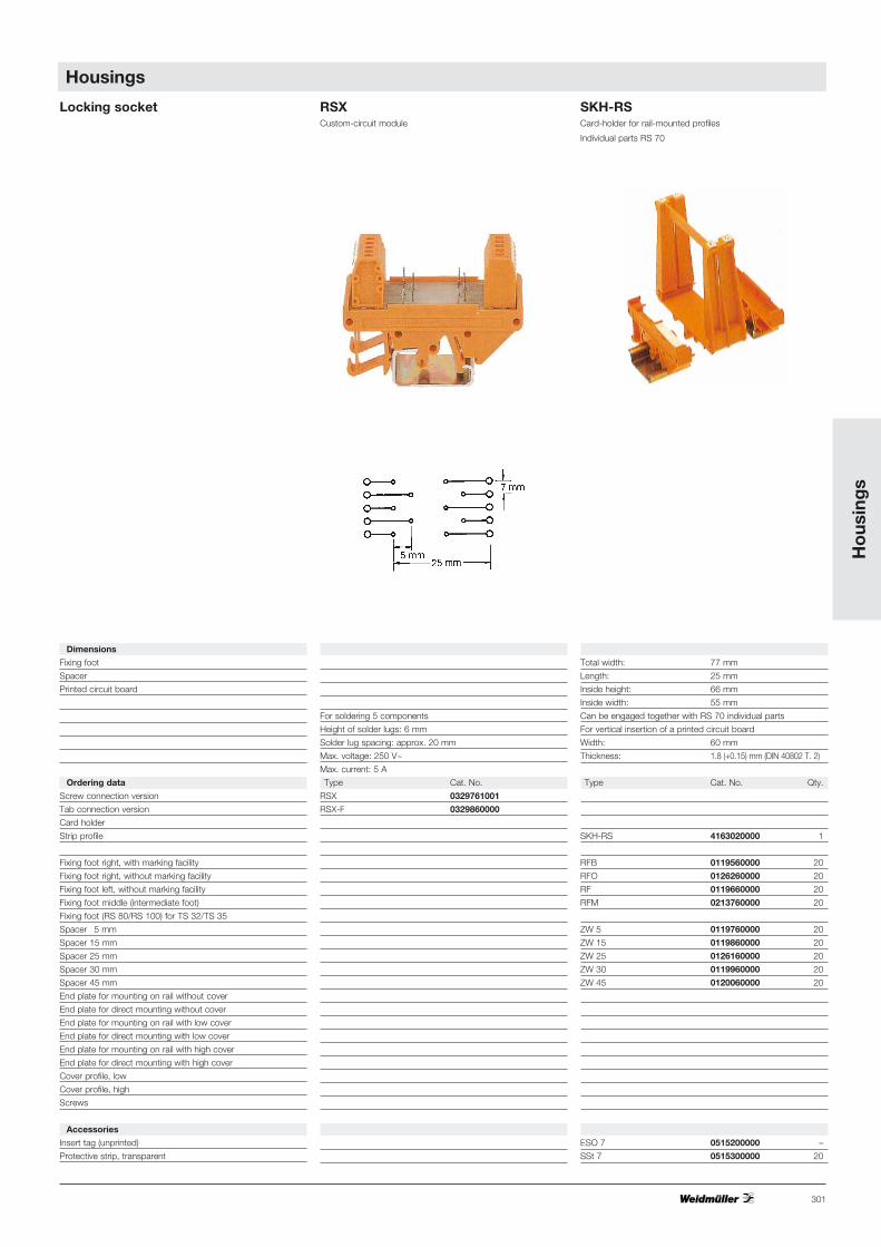
Locking socket RSXCustom-circuit module
SKH-RSCard-holder for rail-mounted profiles
Individual parts RS 70
Dimensions
Fixing foot
Spacer
Printed circuit board
Ordering data
Screw connection version
Tab connection version
Card holder
Strip profile
Fixing foot right, with marking facility
Fixing foot right, without marking facility
Fixing foot left, without marking facility
Fixing foot middle (intermediate foot)
Fixing foot (RS 80/RS 100) for TS 32/TS 35
Spacer 5 mm
Spacer 15 mm
Spacer 25 mm
Spacer 30 mm
Spacer 45 mm
End plate for mounting on rail without cover
End plate for direct mounting without cover
End plate for mounting on rail with low cover
End plate for direct mounting with low cover
End plate for mounting on rail with high cover
End plate for direct mounting with high cover
Cover profile, low
Cover profile, high
Screws
Accessories
Insert tag (unprinted)
Protective strip, transparent
For soldering 5 components
Height of solder lugs: 6 mm
Solder lug spacing: approx. 20 mm
Max. voltage: 250 V~
Max. current: 5 A
Type Cat. No.
RSX 0329761001
RSX-F 0329860000
Total width: 77 mm
Length: 25 mm
Inside height: 66 mm
Inside width: 55 mm
Can be engaged together with RS 70 individual parts
For vertical insertion of a printed circuit board
Width: 60 mm
Thickness: 1.8 (+0.15) mm (DIN 40802 T. 2)
Type Cat. No. Qty.
SKH-RS 4163020000 1
RFB 0119560000 20
RFO 0126260000 20
RF 0119660000 20
RFM 0213760000 20
ZW 5 0119760000 20
ZW 15 0119860000 20
ZW 25 0126160000 20
ZW 30 0119960000 20
ZW 45 0120060000 20
ESO 7 0515200000 –
SSt 7 0515300000 20
Ho
usin
gs
Housings
302
Locking socket RS 45Strip profile
RS 70Locking socket
Individual parts
Dimensions)
Fixing foot
Spacer
Printed circuit board
Rated data
Flammability acc. to UL level
Upper temperature limit
Ordering data
String profile
Fixing foot right, with marking facility
Fixing foot right, without marking facility
Fixing foot left, without marking facility
Fixing foot middle (intermediate foot)
Fixing foot (RS 80/RS 100) for TS 32/TS 35
Spacer 5 mm
Spacer 15 mm
Spacer 25 mm
Spacer 30 mm
Spacer 45 mm
End plate for mounting on rail without cover
End plate for direct mounting without cover
End plate for mounting on rail with low cover
End plate for direct mounting with low cover
End plate for mounting on rail with high cover
End plate for direct mounting with high cover
Cover profile, low
Cover profile, high
Screws
Accessories
Insert tag (unprinted)
Protective strip, transparent
Total width: 45 mm
Length: 1000 mm/2000 mm
For horizontal insertion of a printed circuit board
Width: 42 (+0.5) mm
Thickness: 1.8 (+0.15) mm (DIN 40802 T. 2)
Length: optional/60…2000 mm
Dim. of RS section: printed circuit board length – 4.5 mm
Dim. of ADP section: printed circuit board length – 1 mm
Example: circuit board length 160 mm, RS = 155.5 mm,
ADP = 159 mm
V-0 / V-2 strip profile / accessories
70 °C
Type Cat. No. Qty.
RS 45 (up to 2000 mm) 4027750000 1
RS 45 (up to 1000 mm) 8140880000 1
AP 45/LI AP 45/RE 8143910000 8143900000 20
AP 45/LI Di AP 45/RE Di 8140870000 8140860000 20
30 x 14 4011200000 –
Width: 10 mm Maß RF
Width: 5 mm/15 mm/25 mm/30 mm/45 mm Dim. ZW
Width: RS-Br.–2 mm (Ex.: RS=45 mm, LP=43 mm) Dim. A
Length: 67.8 (–0.2 ) mm Dim. L
Thickness: 1.6 (±0.2) mm (DIN 40802 Part 2)
V-2
100 °C
Type Cat. No. Qty.
RFB 0119560000
RFO 0126260000 20
RF 0119660000 20
RFM 0213760000 20
ZW 5 0119760000 20
ZW 15 0119860000 20
ZW 25 0126160000 20
ZW 30 0119960000 20
ZW 45 0120060000 20
ESO 7 0515200000 –
SSt 7 0515300000 100
AP 45 / LI
AP 45 / LI Di
AP 45/RE Di
AP 45/RE
Housings
303
Ho
usin
gs
RS 80Strip profile
RS 100Strip profile for Euro-cards
Total width: 84 mm
Length: 2000 mm
For horizontal insertion of a printed circuit board
Width: 67.8 (+0.2) mm
Thickness: 1.8 (+0.15) mm (DIN 40802 T. 2)
Dim. RS section printed circuit board length –4.5 mm
Dim. ADP section printed circuit board length –2 mm
Example: circuit board length 160 mm, RS = 155.5 mm,
ADP = 158 mm
V-0 / V-2 strip profile / accessories
70 °C
Type orange (RAL 2000) grey (RAL 7032) Qty.
RS 80 (2000 mm) grey 4183130000 1
RS 80 (2000 mm) orange 4157440000 1
RF 180 1324460000 1773400000 20
AP 80 1324260000 8320300000 20
AP 80 D 1324360000 20
AP RF 80 RE 8156200000 -
AP RF 80 LT 8156210000 -
AP 85 1410860000 20
AP 85 D 1411060000 20
AP 86 1410960000 20
AP 86 D 1411160000 20
ADP 5 (1000 mm) 4167150000 –
ADP 6 (1000 mm) 4167160000 –
30 x 14 4011200000 –
Total width: 104 mm
Length: 2000 mm/160 mm
For horizontal insertion of a printed circuit board
Width: 100 (+0.5) mm
Thickness: 1.8 (+0.5) mm (DIN 40802 Part 2)
Dim. RS section printed circuit board length –4.5 mm
Dim. ADP section printed circuit board length –1 mm
Example: circuit board length 160 mm, RS = 155.5 mm,
ADP = 159 mm
V-0 / V-2 strip profile / accessories
70 °C
Type orange (RAL 2000) grey (RAL 7032) Qty.
RS 100 (2000 mm) grey 4010870000 1
RS 100 (2000 mm) orange 4144870000 1
RS 100 (155 mm) 4148400000 1
RF 180 1324460000 1773400000 20
AP 100 1185060000 1773410000 20
AP 100 D 1185160000 20
AP 110 1185260000 20
AP 110 D 1185360000 20
AP 111 1185460000 20
AP 111 D 1185560000 20
ADP 10 (2000 mm) 4169320000 (2 m)
ADP 11 (2000 mm) 4169330000 (2 m)
40 x 14 4019420000 –
RS 80Screws
Screws
RF 180
AP 80
AP 85
AP 86
ADP 5
ADP 6
AP 80 D
AP 85 D
AP 86 D
AP 110
AP 111
RS 100
ADP 10
ADP 11
AP 100 D
AP 110 D
AP 111 D
AP 100
RF 180
AP RF80 RE/LT
Housings
304
Housings
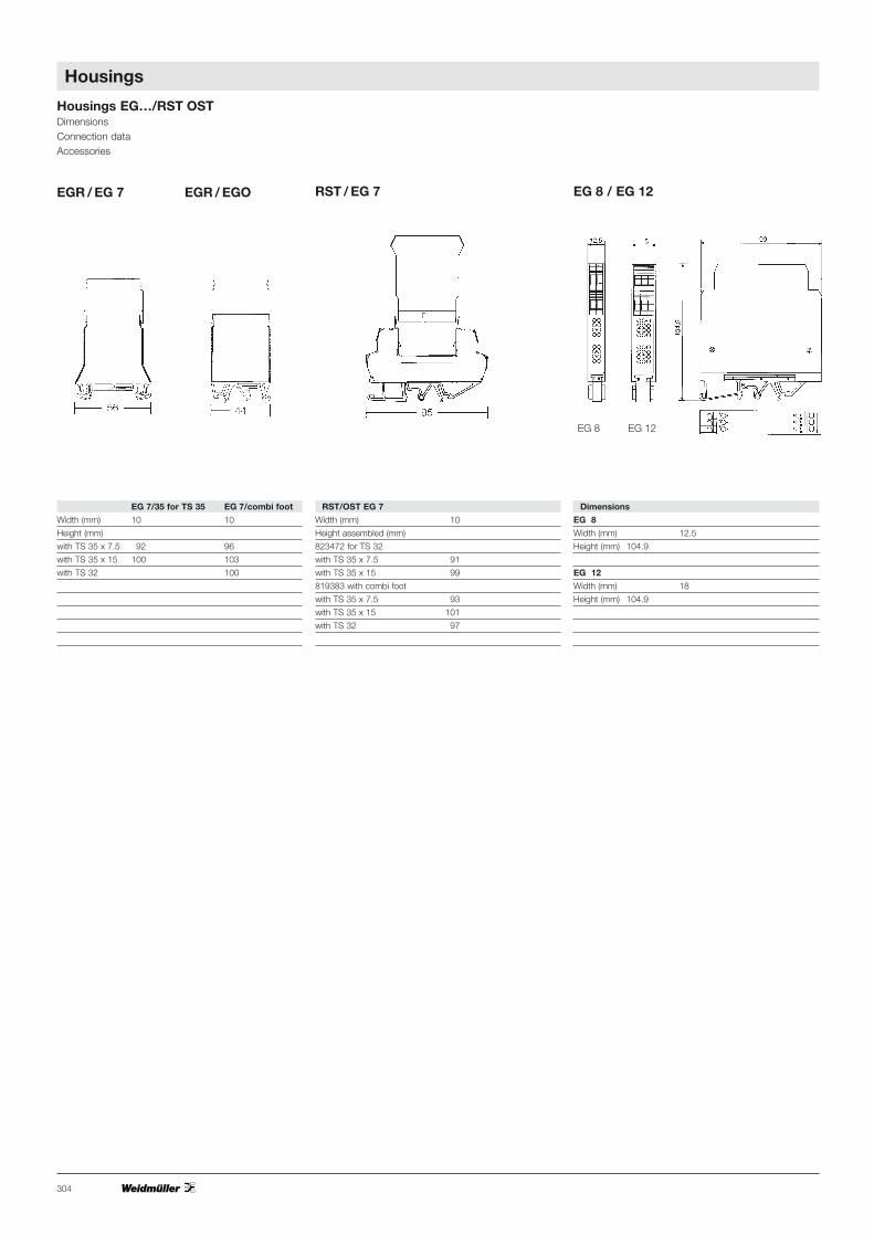
Housings EG…/RST OSTDimensionsConnection dataAccessories
EGR / EG 7 EGR / EGO
EG 7/35 for TS 35 EG 7/combi foot
Width (mm) 10 10
Height (mm)
with TS 35 x 7.5 92 96
with TS 35 x 15 100 103
with TS 32 100
RST/OST EG 7
Width (mm) 10
Height assembled (mm)
823472 for TS 32
with TS 35 x 7.5 91
with TS 35 x 15 99
819383 with combi foot
with TS 35 x 7.5 93
with TS 35 x 15 101
with TS 32 97
Dimensions
EG 8
Width (mm) 12.5
Height (mm) 104.9
EG 12
Width (mm) 18
Height (mm) 104.9
EG 8 EG 12
RST / EG 7 EG 8 / EG 12
Ho
usin
gs
305
Housings
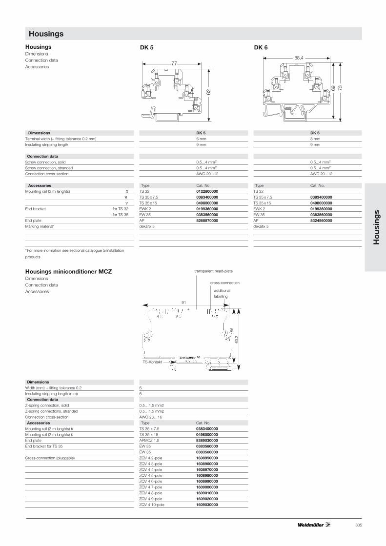
Housings miniconditioner MCZDimensionsConnection dataAccessories
Dimensions
Width (mm) + fitting tolerance 0.2
Insulating stripping length (mm)
Connection data
Z-spring connection, solid
Z-spring connections, stranded
Connection cross-section
Accessories
Mounting rail (2 m lenghts) W
Mounting rail (2 m lenghts) U
End plate
End bracket for TS 35
Cross-connection (pluggable)
6
6
0.5…1.5 mm2
0.5…1.5 mm2
AWG 26…16
Type Cat. No.
TS 35 x 7.5 0383400000
TS 35 x 15 0498000000
APMCZ 1.5 8389030000
EW 35 0383560000
EW 35 0383560000
ZQV 4 2-pole 1608950000
ZQV 4 3-pole 1608960000
ZQV 4 4-pole 1608970000
ZQV 4 5-pole 1608980000
ZQV 4 6-pole 1608990000
ZQV 4 7-pole 1609000000
ZQV 4 8-pole 1609010000
ZQV 4 9-pole 1609020000
ZQV 4 10-pole 1609030000
91
additional
labelling
transparent head-plate
TS-Kontakt
cross-connection
63.2
56
88,4
7369
77
62
Housings DimensionsConnection dataAccessories
DK 5
6 mm
9 mm
0.5...4 mm2
0.5...4 mm2
AWG 20...12
Type Cat. No.
TS 32 0122800000
TS 35 x 7.5 0383400000
TS 35 x 15 0498000000
EWK 2 0199360000
EW 35 0383560000
AP 8268870000
dekafix 5
DK 6
8 mm
9 mm
0.5...4 mm2
0.5...4 mm2
AWG 20...12
Type Cat. No.
TS 32
TS 35 x 7.5 0383400000
TS 35 x 15 0498000000
EWK 2 0199360000
EW 35 0383560000
AP 8324560000
dekafix 5
Dimensions
Terminal width (+ fitting tolerance 0.2 mm)
Insulating stripping length
Connection data
Screw connection, solid
Screw connection, stranded
Connection cross-section
Accessories
Mounting rail (2 m lenghts) Y
W
V
End bracket for TS 32
for TS 35
End plate
Marking material*
*For more inormation see sectional catalogue 5/installation
products
DK 6 DK 5

306
Housings
HousingsEG…/EG-U/LPUDimensionsConnection dataAccessories
EG 1 - Fig. I EG 2 - Fig. II
Dimensions
Terminal width (+fitting tolerance 0.2 mm)
Insulating stripping length
Connection data
Screw connection, solid
Screw connection, stranded
Connection cross-section
Accessories
Mounting rail (2 m lenghts) Y
W
U
End bracket for TS 32
for TS 35
Cross connection wire: 80 mm long, 50-pole/1 mm2
Marking material*
Dimensions
Terminal width (+fitting tolerance 0.2 mm)
Insulating stripping length
Connection data
Screw connection, solid
Screw connection, stranded
Tab connection (DIN 46247)
Connection cross-section
Accessories
Mounting rail (2 m lenghts) Y
W
U
End bracket for TS 32
for TS 35
Cross connection wire: 80 mm long, 50-pole/1 mm2
Marking material*
* see sectional catalogue 7
18 mm
12 mm
0.5…6 mm2
0.5…4 mm2
AWG 20…12
Type Cat. No.
TS 32 0122800000
TS 35 x 7.5 0383400000
TS 35 x 15 0498000000
EKW 2 0199360000
EW 35 0383560000
QD 50/grey 0238700000
dekafix 5
EG 2 – Fig. III
18 mm
2x 0.8 x 2.8 mm or 1x 0.8 x 6.3 mm
Type Cat. No.
TS 32 0122800000
TS 35 x 7.5 0383400000
TS 35 x 15 0498000000
EKW 2 0199360000
EW 35 0383560000
QD 50/grey 0238700000
dekafix 5
20 mm
12 mm
0.5…6 mm2
0.5…4 mm2
AWG 20…12
Type Cat. No.
TS 32 0122800000
TS 35 x 7.5 0383400000
TS 35 x 15 0498000000
EKW 2 0199360000
EW 35 0383560000
QD 50/grey 0238700000
dekafix 5
EG 2 – Fig. IV
18 mm
2x 0.8 x 2.8 mm
Type Cat. No.
TS 32 0122800000
TS 35 x 7.5 0383400000
TS 35 x 15 0498000000
EKW 2 0199360000
EW 35 0383560000
QD 50/grey 0238700000
dekafix 5

Ho
usin
gs
307
Housings
SEG-U/LPU
22.5 mm
17 mm
0.5…4 mm2
0.5…2.5 mm2
Type Cat. No.
TS 32 0122800000
TS 35 x 7.5 0383400000
TS 35 x 15 0498000000
EKW 2 0199360000
EW 35 0383560000
QD 50/grey 0238700000
dekafix 6.5
EG 4 – Fig. VI
22.5 mm
17 mm
0.5…4 mm2
0.5…2.5 mm2
AWG 22…12
Type Cat. No.
TS 32 0122800000
TS 35 x 7.5 0383400000
TS 35 x 15 0498000000
EKW 2 0199360000
EW 35 0383560000
QD 50/grey 0238700000
dekafix 6.5
dekafix 6.5
EG 5 – Fig. VII
22.5 mm
17 mm
0.5…4 mm2
0.5…2.5 mm2
AWG 22…12
Type Cat. No.
TS 32 0122800000
TS 35 x 7.5 0383400000
TS 35 x 15 0498000000
EKW 2 0199360000
EW 35 0383560000
QD 50/grey 0238700000
dekafix 6.5
20 mm
17 mm
0.5…4 mm2
0.5…2.5 mm2
AWG 26…14
Type Cat. No.
TS 32 0122800000
TS 35 x 7.5 0383400000
TS 35 x 15 0498000000
EKW 2 0199360000
EW 35 0383560000
QD 50/grey 0238700000
dekafix 5
EG 6
Type Cat. No.
TS 35 x 7.5 0383400000
TS 35 x 15 0498000000
EW 35 0383560000
dekafix 6.5
with assembly plate MPL with assembly plate MPL
Anreihmaß
EG 3 - Fig. V
308
Housings
Printed circuit board S 22.5 Printed circuit board L 22.5
WAVEBOX S 22.5 WAVEBOX L 22.5
WAVEBOX 17.5WAVEBOX 12.5
Ho
usin
gs
309
Housings
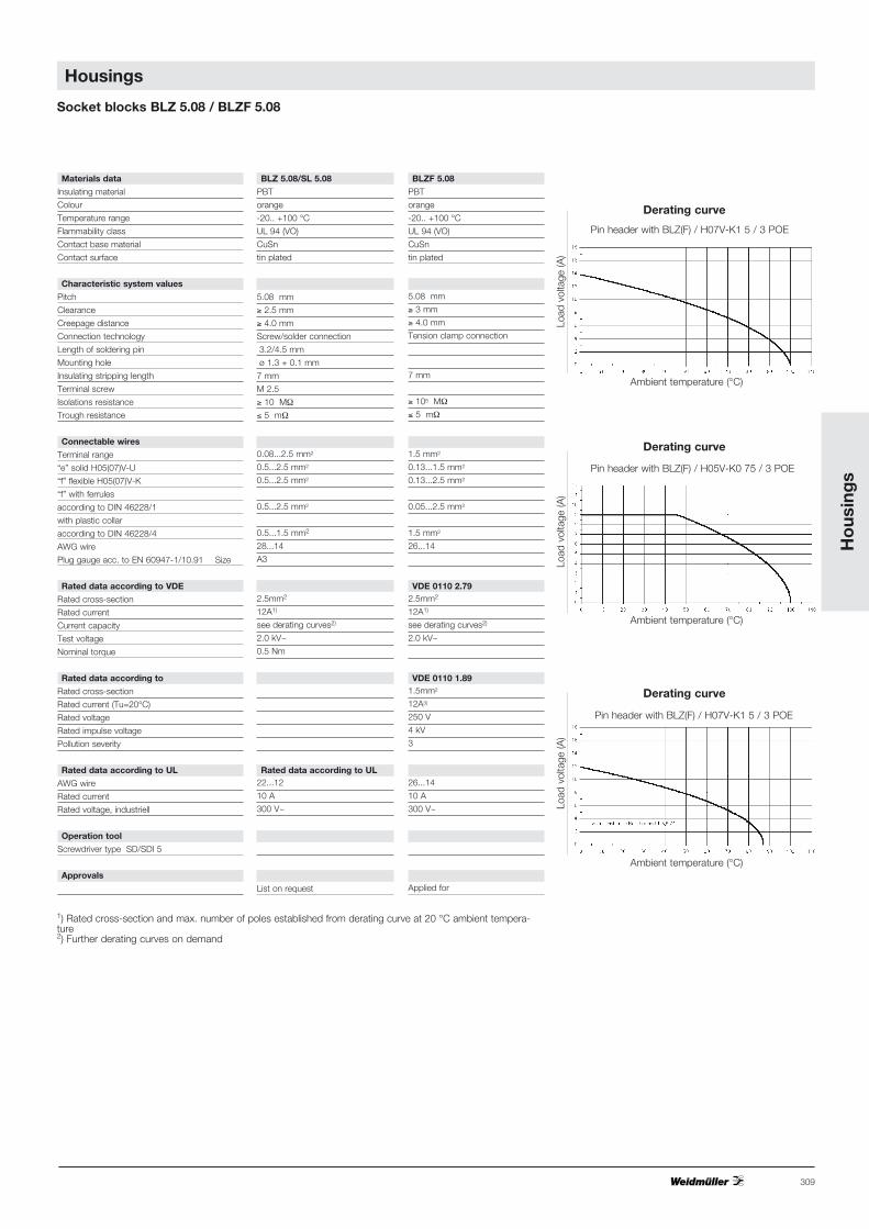
Socket blocks BLZ 5.08 / BLZF 5.08
Materials data
Insulating material
Colour
Temperature range
Flammability class
Contact base material
Contact surface
Characteristic system values
Pitch
Clearance
Creepage distance
Connection technology
Length of soldering pin
Mounting hole
Insulating stripping length
Terminal screw
Isolations resistance
Trough resistance
Connectable wires
Terminal range
“e” solid H05(07)V-U
“f” flexible H05(07)V-K
“f” with ferrules
according to DIN 46228/1
with plastic collar
according to DIN 46228/4
AWG wire
Plug gauge acc. to EN 60947-1/10.91 Size
Rated data according to VDE
Rated cross-section
Rated current
Current capacity
Test voltage
Nominal torque
Rated data according to
Rated cross-section
Rated current (Tu=20°C)
Rated voltage
Rated impulse voltage
Pollution severity
Rated data according to UL
AWG wire
Rated current
Rated voltage, industriell
Operation tool
Screwdriver type SD/SDI 5
Approvals
BLZ 5.08/SL 5.08
PBT
orange
-20.. +100 °C
UL 94 (VO)
CuSn
tin plated
5.08 mm
≥ 2.5 mm
≥ 4.0 mm
Screw/solder connection
3.2/4.5 mm
ø 1.3 + 0.1 mm
7 mm
M 2.5
≥ 10 MΩ
≤ 5 mΩ
0.08...2.5 mm2
0.5...2.5 mm2
0.5...2.5 mm2
0.5...2.5 mm2
0.5...1.5 mm2
28...14
A3
2.5mm2
12A1)
see derating curves2)
2.0 kV~
0.5 Nm
Rated data according to UL22...12
10 A
300 V~
List on request
BLZF 5.08
PBT
orange
-20.. +100 °C
UL 94 (VO)
CuSn
tin plated
5.08 mm
≥ 3 mm
≥ 4.0 mm
Tension clamp connection
7 mm
≥ 105 MΩ
≤ 5 mΩ
1.5 mm2
0.13...1.5 mm2
0.13...2.5 mm2
0.05...2.5 mm2
1.5 mm2
26...14
VDE 0110 2.792.5mm2
12A1)
see derating curves2)
2.0 kV~
VDE 0110 1.891.5mm2
12A3)
250 V
4 kV
3
26...14
10 A
300 V~
Applied for
1) Rated cross-section and max. number of poles established from derating curve at 20 °C ambient tempera-ture2) Further derating curves on demand
Ambient temperature (°C)
Ambient temperature (°C)
Ambient temperature (°C)
Bel
astu
ngss
trom
(A)
Bel
astu
ngss
trom
(A)
(A)
Ambient temperature (°C)
Ambient temperature (°C)
Ambient temperature (°C)
Load
vol
tage
(A)
Load
vol
tage
(A)
Load
vol
tage
(A)
Derating curve
Derating curve
Derating curve
Pin header with BLZ(F) / H07V-K1 5 / 3 POE
Pin header with BLZ(F) / H05V-K0 75 / 3 POE
Pin header with BLZ(F) / H07V-K1 5 / 3 POE
310
Housings
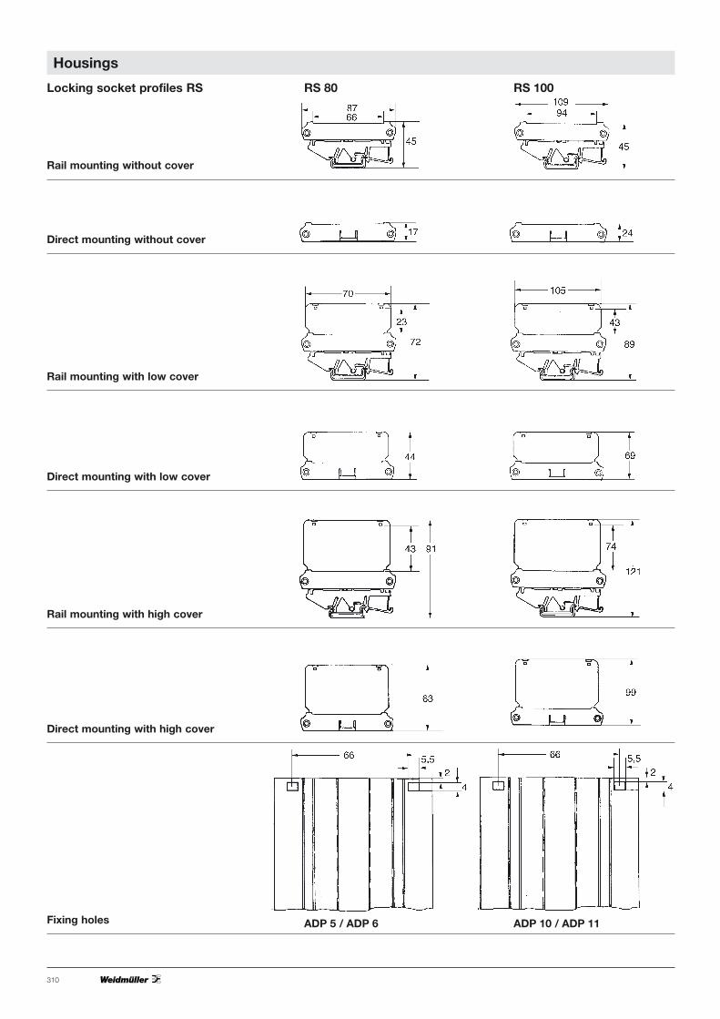
Rail mounting without cover
Locking socket profiles RS RS 80 RS 100
ADP 5 / ADP 6 ADP 10 / ADP 11
Direct mounting without cover
Rail mounting with low cover
Direct mounting with low cover
Rail mounting with high cover
Direct mounting with high cover
Fixing holes
Ho
usin
gs
311
Housings
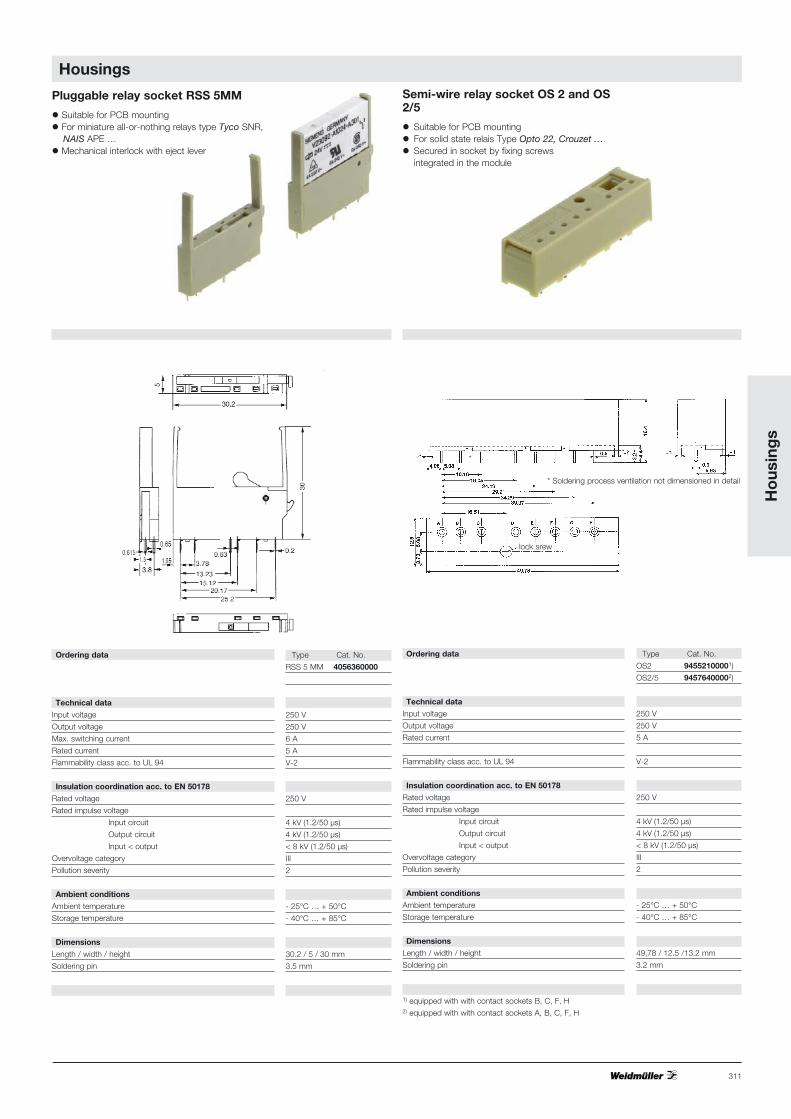
Ordering data
Technical data
Input voltage
Output voltage
Rated current
Flammability class acc. to UL 94
Insulation coordination acc. to EN 50178
Rated voltage
Rated impulse voltage
Input circuit
Output circuit
Input < output
Overvoltage category
Pollution severity
Ambient conditions
Ambient temperature
Storage temperature
Dimensions
Length / width / height
Soldering pin
1) equipped with with contact sockets B, C, F, H2) equipped with with contact sockets A, B, C, F, H
Type Cat. No.
OS2 94552100001)
OS2/5 94576400002)
250 V
250 V
5 A
V-2
250 V
4 kV (1.2/50 µs)
4 kV (1.2/50 µs)
< 8 kV (1.2/50 µs)
III
2
- 25°C … + 50°C
- 40°C … + 85°C
49,78 / 12.5 /13.2 mm
3.2 mm
* Soldering process ventilation not dimensioned in detail
Pluggable relay socket RSS 5MM
Suitable for PCB mountingFor miniature all-or-nothing relays type Tyco SNR,NAIS APE …Mechanical interlock with eject lever
Ordering data
Technical data
Input voltage
Output voltage
Max. switching current
Rated current
Flammability class acc. to UL 94
Insulation coordination acc. to EN 50178
Rated voltage
Rated impulse voltage
Input circuit
Output circuit
Input < output
Overvoltage category
Pollution severity
Ambient conditions
Ambient temperature
Storage temperature
Dimensions
Length / width / height
Soldering pin
Type Cat. No.
RSS 5 MM 4056360000
250 V
250 V
6 A
5 A
V-2
250 V
4 kV (1.2/50 µs)
4 kV (1.2/50 µs)
< 8 kV (1.2/50 µs)
III
2
- 25°C … + 50°C
- 40°C … + 85°C
30.2 / 5 / 30 mm
3.5 mm
*
Semi-wire relay socket OS 2 and OS2/5
Suitable for PCB mountingFor solid state relais Type Opto 22, Crouzet …Secured in socket by fixing screwsintegrated in the module
lock srew