ANSI/ASHRAE/IESNA Standard 90.1-2010 Final Determination ...

1
1 © 2016 ASHRAE Learning Institute
Complying with Standard 90.1-2013:
HVAC/Mechanical
McHenry Wallace Jr., PE, LEED-AP
2016 Fall Online
Monday, September 26, 2016
2 © 2016 ASHRAE Learning Institute
Copyright Materials
• Copyright 2016 by ASHRAE. All rights reserved. No part of this presentation may be reproduced without written permission from ASHRAE, nor may any part of this presentation be reproduced, stored in a retrieval system or transmitted in any form or by any means (electronic, photocopying, recording or other) without written permission from ASHRAE.
• ASHRAE has compiled this presentation with care, but ASHRAE has not investigated and ASHRAE expressly disclaims any duty to investigate any product, service, process, procedure, design or the like, that may be described herein. The appearance of any technical data or editorial material in this presentation does not constitute endorsement, warranty or guaranty by ASHRAE of any product, service, process, procedure, design or the like. ASHRAE does not warrant that the information in this publication is free of errors. The user assumes the entire risk of the use of the use of any information in this presentation.

2
3 © 2016 ASHRAE Learning Institute
About the Instructor
McHenry Wallace Jr., PE, Member ASHRAE, LEED® AP, has been a mechanical contractor, consulting engineer and a registered engineer in Texas for over 30 years. Mack is heavily involved on the front lines of the energy conservation industry, having served for the past 18 years on the ASHRAE Standard 90.1 Committee. He was the engineer of record for many award-winning projects, including the Historic Preservation of the Texas State Capitol Building. Mack was director of design/build services for TXU Energy and responsible for developing and guaranteeing the energy savings on many projects. He has trained hundreds of engineers and architects, world-wide, on ASHRAE 90.1 and is the co-author of the new publication Significant Changes to International Energy Conservation Code and ANSI/ASHRAE/IES Standard 90.1. Currently, Mack splits his time between Jacobs Engineering Group and his own company, WiseWattLLP.
4 © 2016 ASHRAE Learning Institute
AIA/CES Registered Provider
• ASHRAE is a Registered Provider with The American Institute of Architects Continuing Education Systems. Credit earned on completion of this program will be reported to CES Records for AIA members. Certificates of Attendance for non-AIA members are available on request.
• This program is registered with the AIA/CES for continuing professional education. As such, it does not include content that may be deemed or construed to be an approval or endorsement by the AIA of any material of construction or any method or manner of handling, using, distributing, or dealing in any material or product. Questions related to specific materials, methods, and services will be addressed at the conclusion of this presentation.
3
5 © 2016 ASHRAE Learning Institute
GBCI cannot guarantee that course sessions will be delivered to you as submitted to GBCI. However, any course found to be in violation of the standards of the program, or otherwise contrary to the mission of GBCI, shall be removed. Your course evaluations will help us uphold these standards.
Course ID: 920000581
Complying withStandard 90.1-2013:HVAC/MechanicalBy ASHRAE
Approved for:
3General CE hours
0LEED-specific hours
6 © 2016 ASHRAE Learning Institute
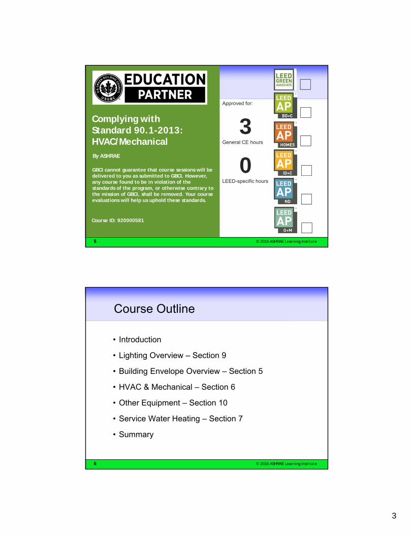
Course Outline
• Introduction
• Lighting Overview – Section 9
• Building Envelope Overview – Section 5
• HVAC & Mechanical – Section 6
• Other Equipment – Section 10
• Service Water Heating – Section 7
• Summary

4
7 © 2016 ASHRAE Learning Institute
Learning Objectives
• Participants will learn of several updates to the Lighting and Building Envelope sections of the 2013 Standard.
• Participants will identify the HVAC portion of the more than 100 updated requirements from previous versions of the standard.
• Participants will practice techniques for achieving 30% or more energy savings from Std 90.1-2004 requirements.
• Participants will explore ways to improve system energy performance in buildings.
8 © 2016 ASHRAE Learning Institute
From National Geographic – Big Idea
…the importance of energy to modern life—it is rightly called the “master resource” that makes all other economic activity possible—Steven F. Hayward

5
9 © 2016 ASHRAE Learning Institute
US Building Energy
• In 2010, the US consumed 19% of global energy consumption
• US buildings:– Use 65% of the nation’s electricity
– Account for over 41% of total primary energy usage
– Space heating, space cooling and lighting use almost half of all energy by buildings
• Total building primary energy in 2009 was 48% higher than in 1980
• A 30% improvement in energy efficiency would generate net positive annual cash flow of $65 billion for buildings
– This would produce a cash flow 4 times better than the average yield for corporate bonds
Source: 2011 Building Energy Data Book, Unlocking American Efficiency (UTC)
10 © 2016 ASHRAE Learning Institute
Historical Efficiency ImprovementsSignificant progress has been made in improving
the energy efficiency of buildings and HVAC equipment

6
11 © 2016 ASHRAE Learning Institute
High Performance for Energy
Source: © ASHRAE, from seminars on Standards 90.1 and 189.1, as modified by Joseph Deringer
Standard 90.1-201054.8 (622)
(90.1-2013?)
12 © 2016 ASHRAE Learning Institute
First-Cost DOE 90.1-2013

7
13 © 2016 ASHRAE Learning Institute
Savings DOE 90.1-2013
https://www.federalregister.gov/articles/2015/11/06/2015-28078/energy-efficiency-standards-for-new-federal-commercial-and-multi-family-high-rise-residential#t-2
14 © 2016 ASHRAE Learning Institute
90.1-2010 – Purpose & Scope
PurposeTo establish the minimum energy efficiency requirements of buildings, other than low-rise residential buildings, for:
1. Design, construction, and a plan for operation and maintenance, and
2. Utilization of on-site, renewable energy resources
ScopeThis standard provides:
a) minimum energy-efficient requirements for the design, construction and a plan for operation and maintenance of:
a) New buildings and their systems
b) New portions of buildings and their systems
c) New systems and equipment in existing buildings
d) New equipment or building systems specifically identified in the standard that are part of industrial or manufacturing processes
b) Criteria for determining compliance with these requirements.

8
15 © 2016 ASHRAE Learning Institute
Organization of Standard 90.1
1 Purpose
2 Scope
3 Definitions, Abbreviations and Acronyms
4 Administration and Enforcement
5 Building Envelope
6 Heating, Ventilating and Air-Conditioning (HVAC)
7 Service Water Heating
8 Power
9 Lighting
10 Other Equipment
11 Energy Cost Budget (ECB) Method
12 Normative References
16 © 2016 ASHRAE Learning Institute
Appendices – 90.1
NORMATIVE (part of standard)A Assembly U-, C- and F-Factor
Determination
B Building Envelope Climate Criteria
C Envelope Trade-Off Methodology
D Climate Data– In 1999 & 2001, envelope
criteria in 26 tables in Appendix B
– In 2004/2007, only 8 tables, now included in text of Envelope section
– Appendix B now contains only climate criteria
INFORMATIVE (not part of standard)E Informative References
F Addenda Description Information (2007/2004/2001)
G Performance Rating Method (2007/2004)

9
17 © 2016 ASHRAE Learning Institute
Alternate Compliance Paths: 4TH Generation 90.1
Energy CostBudget (ECB)
Approach
ENVELOPE
Compliance Performance
Start
EnvelopeMandatory
Requirements
HVACMandatory
Requirements
LightingMandatory
Requirements
HVAC
LIGHTING
PrescriptiveOption
Trade-offOption
Simple SystemOption
PrescriptiveOption
Building AreaOption
Space FunctionOption
Prescriptive
Adapted from S.Taylor/ASHRAE
Appendix G:Performance
RatingSystem
Compliance Performance
Complies Exceeds
18 © 2016 ASHRAE Learning Institute
Integrated Building Design
Lighting
Envelope
Plug Load
HVAC
Outside Air
People
Service Water
Heating
Parking Garage
ExteriorLighting
MINIMIZETHE HVAC LOAD

10
19 © 2016 ASHRAE Learning Institute
LIGHTING OVERVIEW2013
20 © 2016 ASHRAE Learning Institute
Space-by-Space MethodTable 9.6.1, Part 4
Revised2013

11
21 © 2016 ASHRAE Learning Institute
Lighting Controls
22 © 2016 ASHRAE Learning Institute
Climate Zones – Standards 90.1 and 169

12
23 © 2016 ASHRAE Learning Institute
New Climate Zones – Standard 169-2013
90.1-2016
24 © 2016 ASHRAE Learning Institute
World Climate Zones for Standard 169-2013

13
25 © 2016 ASHRAE Learning Institute
Locations Outside the US
Use Either:• Table B-2 (Canada)
• Table B-3 (Selected countries & locations)
• Table B-4 (Definitions of International Climate Zones)
Plus Use:• Appendix B, Section
B2 Major Climate Type Definitions
26 © 2016 ASHRAE Learning Institute
ENVELOPE IMPROVEMENT2013

14
27 © 2016 ASHRAE Learning Institute
Opaque Stringency IncreasesFrom 2004 to 2013 – RoofsBuilding Opaque Envelope Nonresidential Insulation Minimum R-Value Requirements
Climate Zones (CZ)Roofs CZ 1 CZ 2 CZ 3 CZ 4 CZ 5 CZ 6 CZ 7 CZ 8
Insulation Entirely above Deck 90.1-2004 R-15.0 ci R-15.0 ci R-15.0 ci R-15.0 ci R-15.0 ci R-15.0 ci R-15.0 ci R-20.0 ci
90.1-2007 R-15.0 ci R-20.0 ci R-20.0 ci R-20.0 ci R-20.0 ci R-20.0 ci R-20.0 ci R-20.0 ci
90.1-2010 R-15.0 ci R-20.0 ci R-20.0 ci R-20.0 ci R-20.0 ci R-20.0 ci R-20.0 ci R-20.0 ci
90.1-2013 R-20.0 ci R-25.0 ci R-25.0 ci R-30.0 ci R-30.0 ci R-30.0 ci R-35.0 ci R-35.0 ci
Metal Building 90.1-2004 R-19.0 R-19.0 R-19.0 R-19.0 R-19.0 R-19.0 R-19.0R-13.0 + R-
19.0
90.1-2007 R-19.0 R-19.0 R-19.0 R-19.0 R-19.0 R-19.0 R-19.0R-13.0 + R-
19.0
90.1-2010 R-19.0R-13.0 + R-
13.0R-13.0 + R-
13.0R-13.0 + R-
13.0R-13.0 + R-
13.0R-13.0 + R-
19.0R-13.0 + R-
19.0R-13.0 + R-
19.0 Ls
90.1-2013R-10.0 + R-19 FC
R-10.0 + R-19 FC
R-10.0 + R-19 FC
R-19 + R-11 Ls or R-25 + R-8 Ls
R-19 + R-11 Ls or R-25 + R-8 Ls
R-25 + R-11 Ls
R-30 + R-11 Ls
R-25 + R-11 + R-11
Ls
Attic and Other 90.1-2004 R-30.0 R-30.0 R-30.0 R-30.0 R-30.0 R-38.0 R-38.0 R-38.0
90.1-2007 R-30.0 R-38.0 R-38.0 R-38.0 R-38.0 R-38.0 R-38.0 R-49.0
90.1-2010 R-30.0 R-38.0 R-38.0 R-38.0 R-38.0 R-38.0 R-38.0 R-49.0
90.1-2013 R-38.0 R-38.0 R-38.0 R-49.0 R-49.0 R-49.0 R-60.0 R-60.0
28 © 2016 ASHRAE Learning Institute
Glazing Types
• Spectral control – transmit light, reject near-IR heat
• Equal daylight with only 50% of solar gain
• IG to minimize SHGC
Technology:• Selective absorbers
– Blue-green tints
• Selective reflectors– Modified low-E coatings– Coated glass and plastic– Multi-layer dielectric Transmittance -vs- Wavelength
Source: LBNL, Building Technology

15
29 © 2016 ASHRAE Learning Institute
Table 5.5-1:Climate Zone 1A, Fenestration Elements only
Categories of Construction
Space Conditioning Categories
New
30 © 2016 ASHRAE Learning Institute
Light-to-Solar Gain Ratio for insulating glass units for all glasses in LBNL International Glazing Data Base (IGDB)
Light-to-Solar Gain RatioLSG = 2.0
Tvis
SHGC
CZ 1-3 CZ 4-6CZ 7-8 non-res.
New VT/SHGC ≥ 1.10 Req. in 2013
LSG = 1.0
LSG: Light-to-Solar Gain Ratio = VT / SHGC

16
31 © 2016 ASHRAE Learning Institute
Fenestration Prescriptive Req.:90.1-2004 thru 90.1-2013
Max. U, of Fenestration Assembly
Max. SHGC, of Fenestration Assembly
Vertical Fenestration, ≤ 40% of Wall CZ 1 CZ 2 CZ 3 CZ 3C CZ 4 CZ 5 CZ 6 CZ 7 CZ 8 CZ 1 CZ 2 CZ 3CZ 3C
CZ 4 CZ 5 CZ 6 CZ 7 CZ 8
90.1-2004 Fixed, all, <= 40%1.2 1.2 0.6 1.22 0.6 0.6 0.6 0.6 0.5
All at 20%
0.25 0.25 0.25 0.39 0.39 0.39 0.39 0.49 NR
Fixed, north, <= 40% N at 20% 0.61 0.61 0.49 0.61 0.49 0.49 0.49 0.64 NR
Operable, all, <= 40%1.3 1.3 0.7 1.27 0.7 0.7 0.7 0.7 0.5
All at 40%
0.25 0.25 0.25 0.34 0.39 0.39 0.39 0.49 NR
Operable, north, <= 40% N at 40% 0.44 0.61 0.39 0.61 0.49 0.49 0.49 0.64 NR
90.1-2007 Nonmetal framing, all 1.20 0.75 0.65 0.40 0.35 0.35 0.35 0.35
0.25 0.25 0.25 0.40 0.40 0.40 0.45 0.45
Metal framing, curtainwalletc.
1.20 0.70 0.60 0.50 0.45 0.45 0.40 0.40
Metal framing, all other 1.20 0.75 0.65 0.55 0.55 0.55 0.45 0.45
Metal framing, entrance door
1.20 1.10 0.90 0.85 0.80 0.80 0.80 0.80
90.1-2010 Nonmetal framing, all 1.20 0.75 0.65 0.40 0.35 0.35 0.35 0.35
0.25 0.25 0.25 0.40 0.40 0.40 0.45 0.45
Metal framing, curtainwalletc.
1.20 0.70 0.60 0.50 0.45 0.45 0.40 0.40
Metal framing, all other 1.20 0.75 0.65 0.55 0.55 0.55 0.45 0.45
Metal framing, entrance door
1.20 1.10 0.90 0.85 0.80 0.80 0.80 0.80
90.1-2013 Nonmetal framing, all 0.5 0.4 0.35 0.35 0.32 0.32 0.32 0.32
0.25 0.25 0.25 0.40 0.40 0.40 0.45 0.45Metal framing, fixed 0.57 0.57 0.50 0.42 0.42 0.42 0.38 0.38
Metal framing, operable 0.65 0.65 0.60 0.50 0.50 0.50 0.40 0.40
Metal framing, entrance door
1.10 0.83 0.77 0.77 0.77 0.77 0.77 0.77
32 © 2016 ASHRAE Learning Institute
If Glass Cannot Be Avoided — Shade It
Shaded – 88oF
Not shaded – 121oF

17
33 © 2016 ASHRAE Learning Institute
Fenestration & Doors
NFRC shall be used to determine compliance for:• U-Factor
– NFRC 100
• Solar Heat Gain Coefficient– NFRC 200
• Visible Light Transmittance– NFRC 200
• Air Leakage– NFRC 400
References to updated NFRC test procedures were updated via Addendum q to 90.1-2010.
34 © 2016 ASHRAE Learning Institute
Comfort Chart

18
35 © 2016 ASHRAE Learning Institute
BLUE BOX IS COMFORT ZONE 0.5% HOURS NATURALLY COMFORTABLE
36 © 2016 ASHRAE Learning Institute
BLUE BOX IS COMFORT ZONE 0.9% HOURS NATURALLY COMFORTABLE

19
37 © 2016 ASHRAE Learning Institute
Dew Point – When Things Sweat
38 © 2016 ASHRAE Learning Institute
Climate Consultant: Temperature and Dew Point

20
39 © 2016 ASHRAE Learning Institute
40 © 2016 ASHRAE Learning Institute

21
41 © 2016 ASHRAE Learning Institute
HVAC & MECHANICALSection 6
42 © 2016 ASHRAE Learning Institute
Refrigeration New for 2013 (see 6.5.11-6.4.5-6.4.6)
• 6.1.1.1 New Buildings. Mechanical equipment and systems serving the heating, cooling, ventilating or refrigeration needs of new buildings shall comply with the requirements of this section as described in Section 6.2.
• 6.1.1.2 Additions to Existing Buildings. Mechanical equipment and systems serving the heating, cooling, ventilating or refrigeration needs of additions to existing buildings shall comply with the requirements of this section as described in Section 6.2.
• 6.1.1.3.1 New HVACR equipment as a direct replacement of existing HVACR equipment shall comply with the specific minimum efficiency requirements applicable to that equipment.

22
43 © 2016 ASHRAE Learning Institute
New Definition for Piping
piping: the pipes or tubes interconnecting the various parts of a fluid distribution system, including all elements that are in series with the fluid flow, such as pumps, valves, strainers and air separators, but not including elements that are not in series with the fluid flow, such as expansion tanks, fill lines, chemical feeders, and drains
44 © 2016 ASHRAE Learning Institute
The Requirement Number is a Guide

23
45 © 2016 ASHRAE Learning Institute
6.4.2 Load Calculations
HVAC
Outside Air
People
6.4.2.2 Pump Head must be calculated along with pressure drop in critical circuit
Lighting
Envelope
Plug Load
46 © 2016 ASHRAE Learning Institute
HVAC as a System
HVAC
Cooling/
Heating
Heat
Rejection
Equipment Efficiency
Fans
Pumps
System
Controls Sizing
Air Side Sensible Load:Q = (1.08)*CFM*(MixedAirT –
SupplyAirT)
Water Side Load:Q=500*∆T*GPM

24
47 © 2016 ASHRAE Learning Institute
6.4.1 Minimum Equipment Efficiency
Tables 6.8.1-1 through 6.8.1-13 –List mandatory minimum
equipment efficiency requirements
When more than one requirement
is listed, you must comply
with both requirements
If the equipment is not listed or if it
is operated outside the listed range, it can be
used without requirements
Added • Commercial
Refrigeration 2 tables
• Changed the water to air heat pumps
• Changes to 6.8.1-1, 2, 3 & 4
• Changes to 6.8.1-6• Changes to 6.8.1-7
48 © 2016 ASHRAE Learning Institute
Chiller Requirements1.25 KW/Ton

25
49 © 2016 ASHRAE Learning Institute
Unitary Systems New Rating in 2010 Part-Load Rating
11.2 EER11.4 IEER
50 © 2016 ASHRAE Learning Institute
Variable Refrigerant Flow – Covered in 2010
26
51 © 2016 ASHRAE Learning Institute
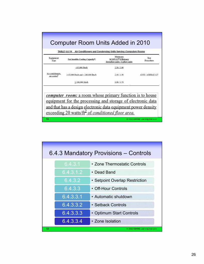
Computer Room Units Added in 2010
52 © 2016 ASHRAE Learning Institute
6.4.3 Mandatory Provisions – Controls
• Zone Thermostatic Controls6.4.3.1
• Dead Band6.4.3.1.2
• Setpoint Overlap Restriction6.4.3.2
• Off-Hour Controls6.4.3.3
• Automatic shutdown6.4.3.3.1
• Setback Controls6.4.3.3.2
• Optimum Start Controls6.4.3.3.3
• Zone Isolation6.4.3.3.4

27
53 © 2016 ASHRAE Learning Institute
6.4.3.1 Zone Thermostatic Controls
zone, HVAC: a space or group of spaces within a building with heating and cooling requirements that are sufficiently similar so that desired conditions (e.g., temperature) can be maintained throughout using a single sensor (e.g., thermostat or temperature sensor).
6.4.3.1.1 General. The supply of heating and cooling energy to each zone shall be individually controlled by thermostatic controls responding to temperature within the zone. For the purposes of Section 6.4.3.1, a dwelling unit shall be permitted to be considered a single zone.
54 © 2016 ASHRAE Learning Institute
HVAC Mandatory Section –Perimeter System Controls
Single zone OK for these small exposures
Separate zone required for each of these long exposures
Building Plan - HVAC Zones

28
55 © 2016 ASHRAE Learning Institute
HVAC Mandatory Section 6.4.3 Controls
• 5ºF Deadband minimum – Cooling: 73ºF– Heating: 68ºF
• Setpoint overlap
• Off-hour controls– Automatic shutdown– Setback– Optimum start– Shutoff dampers– Zone isolation
56 © 2016 ASHRAE Learning Institute
HVAC Mandatory Provisions 6.4.3.3.4 Zone Isolation
Fan with variable speed drive
Areas no larger than 1 story nor >25,000 ft2

29
57 © 2016 ASHRAE Learning Institute
6.4.3.4 HVAC Mandatory Section Ventilation System Controls
6.4.3.4.1 Stair and shaft vents: Motorized dampers required to shut off air
except during life safety event
6.4.3.4.2 Outdoor air intakes, vents, etc., must have motorized dampers:
6.4.3.4.3 Damper Leakage per table
6.4.3.4.4 Ventilation Fan Controls for fans larger than 0.75 hp to shut off fans when not required
58 © 2016 ASHRAE Learning Institute
Where dampers are required by the standard,they shall meet the following leakage limits:
Table 6.4.3.4.3 Maximum Damper Leakage (HVAC Mandatory Section)
30
59 © 2016 ASHRAE Learning Institute
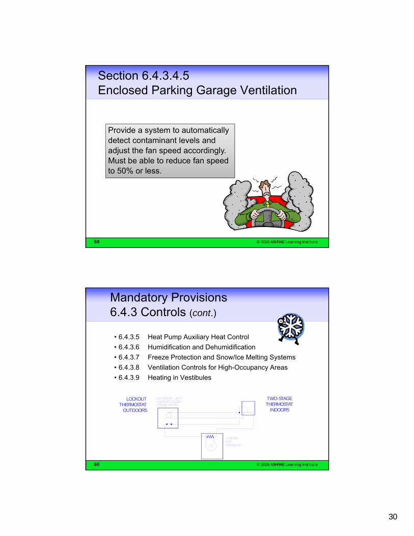
Section 6.4.3.4.5Enclosed Parking Garage Ventilation
Provide a system to automatically detect contaminant levels and adjust the fan speed accordingly. Must be able to reduce fan speed to 50% or less.
60 © 2016 ASHRAE Learning Institute
Mandatory Provisions 6.4.3 Controls (cont.)
• 6.4.3.5 Heat Pump Auxiliary Heat Control
• 6.4.3.6 Humidification and Dehumidification
• 6.4.3.7 Freeze Protection and Snow/Ice Melting Systems
• 6.4.3.8 Ventilation Controls for High-Occupancy Areas
• 6.4.3.9 Heating in Vestibules
LOCKOUT THERMOSTAT
OUTDOORS
TWO-STAGE THERMOSTAT
INDOORS

31
61 © 2016 ASHRAE Learning Institute
6.4.3.8 Ventilation Controls
Demand control ventilation (DCV): A ventilation system capability that provides for the automatic reduction of outdoor air intake below design rates when the actual occupancy of spaces served by the system is less than design occupancy.
62 © 2016 ASHRAE Learning Institute
DCV Control
6.4.3.9 Ventilation Controls for High-Occupancy Areas. Demand control ventilation (DCV) is required for spaces larger than 500 ft2 and with a design occupancy for ventilation of greater than 25 people per 1000 ft2 of floor area.

32
63 © 2016 ASHRAE Learning Institute
CO2 TracksOccupancy
The metabolic rate of people is predictable, so that as people enter a space, the total CO2
production can be predicted
64 © 2016 ASHRAE Learning Institute
6.4.3.9 Heating in Vestibules
Heating allowed only when the outdoor temperature is below 45ºF and with a maximum setpointtemperature of 60ºF.Good exception for using transfer air.

33
65 © 2016 ASHRAE Learning Institute
6.4.3.10 Direct Digital Control (DDC) Requirements (Shall be Provided)
66 © 2016 ASHRAE Learning Institute
6.4.3.10.2 DDC Controls
The DDC system shall be capable of all of
the following, as required, to provide
the control logic required in Section 6.5:
Monitoring zone and system
demand for fan pressure, pump
pressure, heating and cooling
Transferring zone and system
demand information from
zones to air distribution system
controllers and from air distribution
systems to heating and cooling plant
controllers
Automatically detecting those
zones and systems that may be
excessively driving the reset logic and generate an alarm or other indication
to the system operator
Readily allowing operator removal of
zone(s) from the reset algorithm
34
67 © 2016 ASHRAE Learning Institute
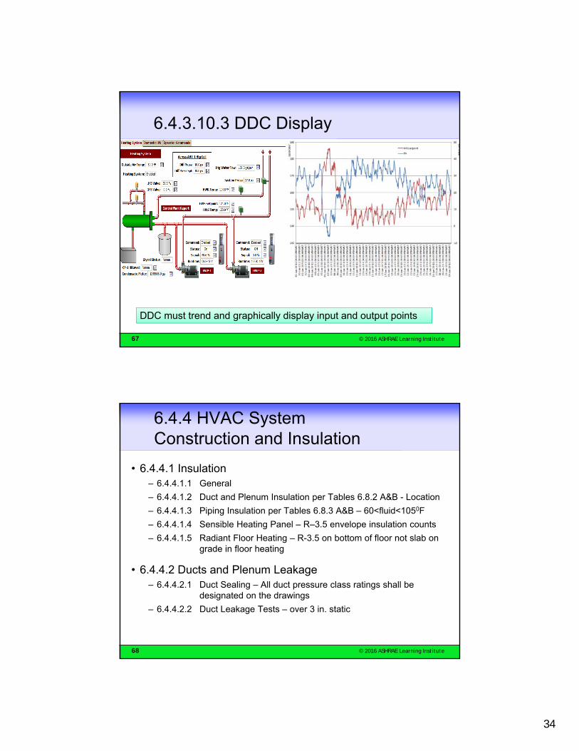
6.4.3.10.3 DDC Display
DDC must trend and graphically display input and output points
68 © 2016 ASHRAE Learning Institute
6.4.4 HVAC SystemConstruction and Insulation
• 6.4.4.1 Insulation– 6.4.4.1.1 General
– 6.4.4.1.2 Duct and Plenum Insulation per Tables 6.8.2 A&B - Location
– 6.4.4.1.3 Piping Insulation per Tables 6.8.3 A&B – 60<fluid<1050F
– 6.4.4.1.4 Sensible Heating Panel – R–3.5 envelope insulation counts
– 6.4.4.1.5 Radiant Floor Heating – R-3.5 on bottom of floor not slab on grade in floor heating
• 6.4.4.2 Ducts and Plenum Leakage– 6.4.4.2.1 Duct Sealing – All duct pressure class ratings shall be
designated on the drawings
– 6.4.4.2.2 Duct Leakage Tests – over 3 in. static

35
69 © 2016 ASHRAE Learning Institute
HVAC Mandatory Section 6.4.4.1.3 Piping Insulation
A chilled water system is designed for a chilled water supply temperature of 440F with a 160F range. Is insulation required on the return piping?
No, the return piping design temperature is 600F. This is a minimum code; watch out for part-load conditions.
70 © 2016 ASHRAE Learning Institute
6.4.5 Walk-in Coolers and Freezers
Automatic door closers
Curtains or other methods to minimize infiltration
Minimum Insulation Coolers R-25 and Freezers R-32 & Freezer Floor R-28
ECMs for fan motors ≤ 1 HP condenser and evaporator
Light efficacy minimum 40 lm/watt or timer to shut off in 15 min
Freezer Glass: triple-pane gas filled or heat-reflective
Cooler Glass: double pane and heat-reflective or triple-pane gas filled or heat-reflective
Freezers anti-sweat heaters WO control power draw ≤ 7.1 W/ft2 of door opening
Coolers anti-sweat heaters WO control power draw ≤ 3.0 W/ft2 of door opening
Freezers use temperature-based defrost termination control

36
71 © 2016 ASHRAE Learning Institute
6.4.6 Refrigerated Display Case
Lighting shall have one of the following:
Low temperature display case
Anti-sweat heater controls
• Automatic time switch
• Motion sensors with minimum 50% reduction
• Temperature-based defrost termination control
• Control terminates on upper temperature then time limit
• RH of air outside glass, OR
• Condensation on inner glass
72 © 2016 ASHRAE Learning Institute
HVAC Prescriptive Section 6.5.1 Economizers – Can be traded off Economizers
– Every system with a fan shall have either air- or water-side economizers
– Climate-dependent requirements based on DOE-2 analysis and bin analysis
6.5.1.1.1 Sized to provide 100% of the design CFM as Outdoor Air for cooling
6.5.1.1.2 Control off supply air temperature (not mixed air temperature)
6.4.3.3.4 Both outdoor air and return air dampers shall meet leakage requirements of Table 6.4.3.3.4
6.5.1.1.5 Means must be provided to relieve excess outdoor air to prevent over-pressurization
6.5.1.1.5 Relief air outlet located to avoid recirculation

37
73 © 2016 ASHRAE Learning Institute
Economizers
No Econ 1b
74 © 2016 ASHRAE Learning Institute
HVAC Prescriptive Section 6.5.1(i) Economizer Exception
38
75 © 2016 ASHRAE Learning Institute
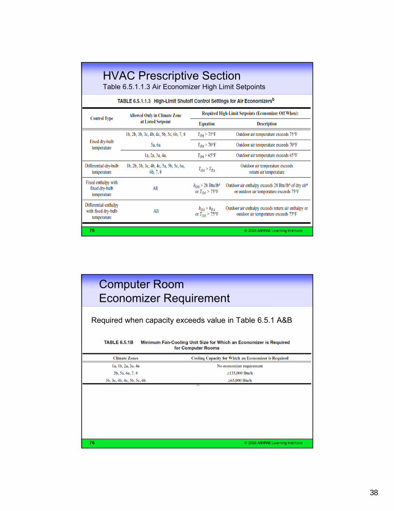
HVAC Prescriptive Section Table 6.5.1.1.3 Air Economizer High Limit Setpoints
76 © 2016 ASHRAE Learning Institute
Computer RoomEconomizer Requirement
Required when capacity exceeds value in Table 6.5.1 A&B
39
77 © 2016 ASHRAE Learning Institute
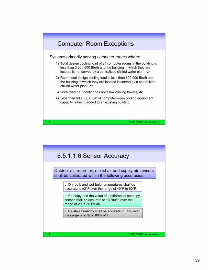
Computer Room Exceptions
Systems primarily serving computer rooms where:
1) Total design cooling load of all computer rooms in the building is less than 3,000,000 Btu/h and the building in which they are located is not served by a centralized chilled water plant, or
2) Room total design cooling load is less than 600,000 Btu/h and the building in which they are located is served by a centralized chilled water plant, or
3) Local water authority does not allow cooling towers, or
4) Less than 600,000 Btu/h of computer room cooling equipment capacity is being added to an existing building.
78 © 2016 ASHRAE Learning Institute
6.5.1.1.6 Sensor Accuracy
Outdoor air, return air, mixed air and supply air sensors shall be calibrated within the following accuracies:
a. Dry-bulb and wet-bulb temperatures shall be accurate to ±2°F over the range of 40°F to 80°F.
b. Enthalpy and the value of a differential enthalpy sensor shall be accurate to ±3 Btu/lb over the range of 20 to 36 Btu/lb.
c. Relative humidity shall be accurate to ±5% over the range of 20% to 80% RH.

40
79 © 2016 ASHRAE Learning Institute
How to Recognize Integrated Economizers – 6.5.1.3
Basic control sequence:• When the outdoor air condition is below the lock-out setpoint, upon
a call for cooling, the economizer outdoor air damper is modulated to maintain a supply air temperature of 53oF to 57oF.
If outdoor air alone cannot satisfy the cooling requirement:
• Integrated control sequence• The economizer outdoor air damper is maintained at 100% open and the
compressor is cycled as the second stage of cooling.
• Non-integrated control sequence• The compressor is energized. The economizer outdoor air damper position will
be determined by the resulting supply air temperature.
80 © 2016 ASHRAE Learning Institute
6.5.1.3 – Added Requirement b.
Units that include an air economizer shall comply with the following:
b. DX units that control the capacity of the mechanical cooling directly based on occupied space temperature shall have a minimum of two stages of mechanical cooling capacity per the following effective dates:
75,000 Btu/h Rated Capacity—Effective 1/1/2014
65,000 Btu/h Rated Capacity—Effective 1/1/2016

41
81 © 2016 ASHRAE Learning Institute
6.5.1.4 DX Cooling Stage Requirements
Effective 1/1/2014, all other DX units, including those that control space temperature by modulating the airflow to the space, shall comply with the requirements of Table 6.5.1.4.
82 © 2016 ASHRAE Learning Institute
HVAC Prescriptive Section 6.5.1.2.1 Water-Side Economizers
• Shall provide 100% of expected cooling load at outdoor air conditions less than 50oF drybulb / 45oF wetbulb
• Procedure:–Recalculate cooling loads assuming normal design assumptions
except with outdoor air set to 50oF / 45oF
–Determine what supply air temperature is required based on system type and controls
–Use coil selection program to determine required condenser water temperature to meet load
–Use tower selection program to determine if tower can provide required CW temp at 45oF wetbulb
42
83 © 2016 ASHRAE Learning Institute
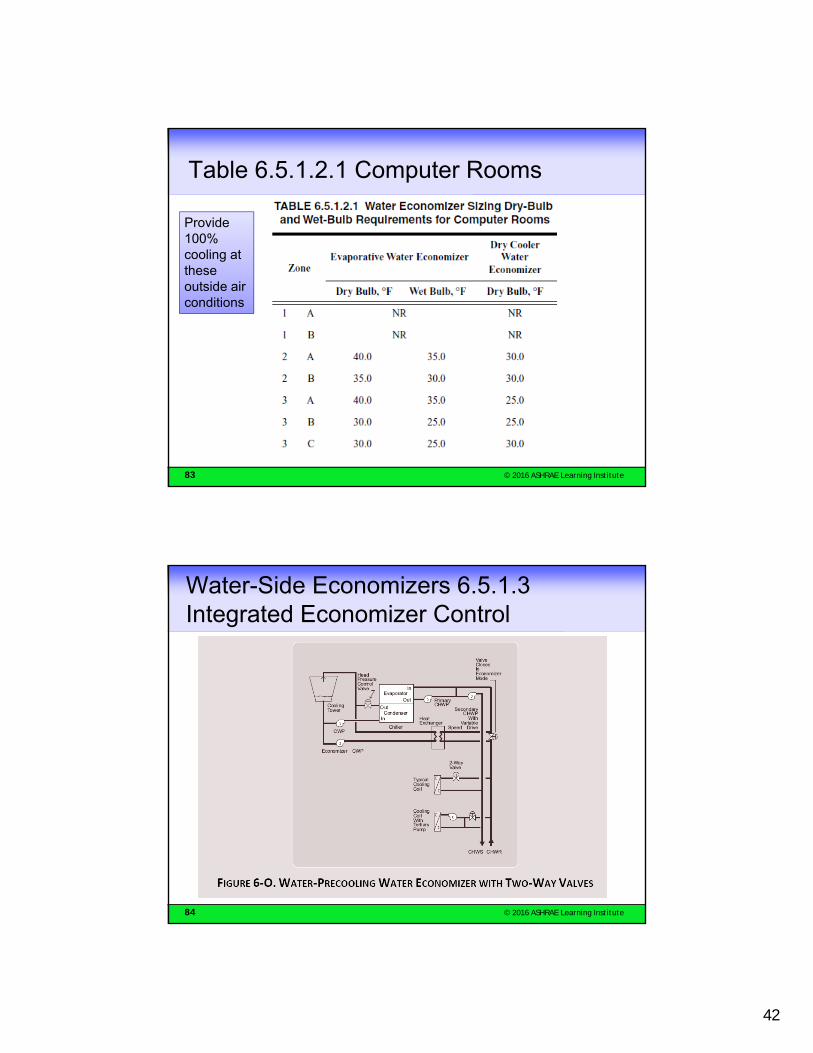
Table 6.5.1.2.1 Computer Rooms
Provide 100% cooling at these outside air conditions
84 © 2016 ASHRAE Learning Institute
Water-Side Economizers 6.5.1.3 Integrated Economizer Control

43
85 © 2016 ASHRAE Learning Institute
HVAC Prescriptive Requirements Economizer Heating Impact
Single-Fan Dual Duct system:
not allowed with air economizer
86 © 2016 ASHRAE Learning Institute
6.5.2 Simultaneous Heating and Cooling Limitation
6.5.2.1 Zone Controls• No reheating
• No recooling
• No mixing hot and cold
• No simultaneous heating and cooling of same zone
6.5.2.2 HydronicSystem Controls• 6.5.2.2.1 Three-Pipe
System (Not Allowed)
• 6.5.2.2.2 Two-Pipe Changeover System (Allowed With Limitations)
• 6.5.2.2.3 Hydronic(Water Loop) Heat Pump Systems
6.5.2.3 Dehumidification –Some allowed• Reduce supply air by
50%
• Lower than 40,000 Btu/h capacity
• Special spaces
• 75% of site recovered heat (including condenser heat)
• 90% recovered energy used to reheat
• Desiccant systems
6.5.2.4
.1 Humidification –Water-side economizer for humidity control with dewpoint above 35ºF
.2 preheating jacket shut-off valve
.3 insulate humidifier dispersion tube if used with cooling

44
87 © 2016 ASHRAE Learning Institute
HVAC Prescriptive Requirements6.5.2.1 Zone Reheat Limitation (No DDC)
Minimum Setpoint no larger than the larger of:
• 30% of peak
• 0.4 cfm/ft2
• Min. OA vent. rate
• 300 cfm
• Approved alternate
• Required by other codes
HOT WATER
Reheat Energy
VAV Reheat Zone
88 © 2016 ASHRAE Learning Institute
HVAC Prescriptive Requirements 6.5.2.1 Zone Reheat Limitation (with DDC)
• 20% of design peak airflow
• Reheated air can be 50% of design peak airflow
• Air between dead band and full heating or cooling is modulated

45
89 © 2016 ASHRAE Learning Institute
EXCEPTIONS: • WARM-UP OR SETBACK• LABS
6.5.2.1.1 Overhead Supply Air Temperatures Limited
90 © 2016 ASHRAE Learning Institute
6.5.3 Air System Design and Control
6.5.3.1 Fan System Power and Efficiency
6.5.3.1.1 Allowable Fan HP
6.5.3.1.2 Motor Nameplate Horsepower
6.5.3.2 Fan Control
6.5.3.2.1 Fan Airflow Control
6.5.3.2.2 VAV Static Pressure Sensor Location
6.5.3.2.3 VAV Setpoint Reset
6.5.3.3 Multiple-Zone VAV System Ventilation Optimization Control
6.5.3.4 Supply Air Temperature Reset Controls
6.5.3.5 Fractional Horsepower Fan Motors

46
91 © 2016 ASHRAE Learning Institute
Fan Power Table
92 © 2016 ASHRAE Learning Institute
Included and Excluded Fans

47
93 © 2016 ASHRAE Learning Institute
Pressure Drop Table 6.5.3.1-2
94 © 2016 ASHRAE Learning Institute
Motor Selection
• 6.5.3.1.2 Motor Nameplate Horsepower: For each fan, the selected fan motor shall be no larger than the first available motor size greater than the brake horsepower. The fan brake horsepower must be indicated on the design documents to allow for compliance verification by the code official.
• Exceptions to 6.5.3.1.2:
a. For fans less than 6 bhp, where the first available motor larger than the
brake horsepower has a nameplate rating within 50% of the brake
horsepower, the next larger nameplate motor size may be selected.
b. For fans 6 bhp and larger, where the first available motor larger than the
brake horsepower has a nameplate rating within 30% of the brake
horsepower, the next larger nameplate motor size may be selected.

48
95 © 2016 ASHRAE Learning Institute
6.5.3.1.3 Fan Efficiency
FEG (fan efficiency grade) ≥ 67
Design total efficiency ≥ maximum fan total efficiency -15%-points
From amca.org website
96 © 2016 ASHRAE Learning Institute
6.5.3.2.1 Fan Airflow Control
DX and chilled water units controlled directly by space temperature shall have:• Min of 2 speed with low ≤ 66%• At low speed, the power ≤ 40%
DX and chilled water units controlling space temperature by varying airflow shall have:• Modulate fan speed low ≤ 50%• At low speed, the power ≤ 30%

49
97 © 2016 ASHRAE Learning Institute
6.5.3.2 Fan Control Effective Dates
98 © 2016 ASHRAE Learning Institute
HVAC Prescriptive Section 6.5.3.2.2Static Pressure Sensor Location
• 6.5.3.2.3 VAV Setpoint Reset– For systems with digital control at zone level, setpoint must
be reset based on zone requiring greatest pressure.
– The setpoint is reset lower until one zone damper is nearly wide open.
• 6.5.3.2.2 VAV Sensor controlling fan must be located such that its setpoint ≤ 1.2 in. wc
– If this results in the sensor being located downstream of major duct splits, multiple sensors shall be installed in each major branch. Exception: Systems using 6.5.3.2.3

50
99 © 2016 ASHRAE Learning Institute
6.5.3.3 VAV Ventilation OptimizationMulti-zone systems with DDC box control must use ASHRAE 62.1 Appendix A - Vent Op
100 © 2016 ASHRAE Learning Institute
Temperature Reset Controls
-SA
X
0.25
51
101 © 2016 ASHRAE Learning Institute
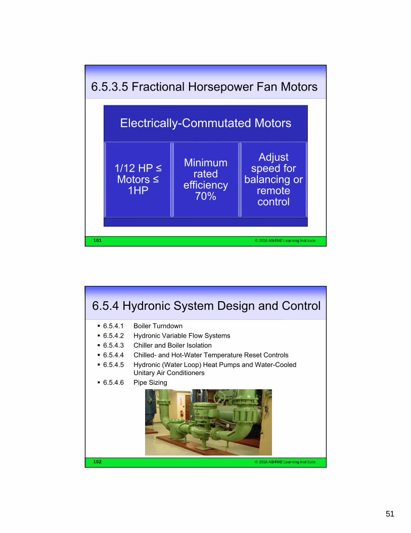
6.5.3.5 Fractional Horsepower Fan Motors
Electrically-Commutated Motors
1/12 HP ≤ Motors ≤
1HP
Minimum rated
efficiency 70%
Adjust speed for
balancing or remote control
102 © 2016 ASHRAE Learning Institute
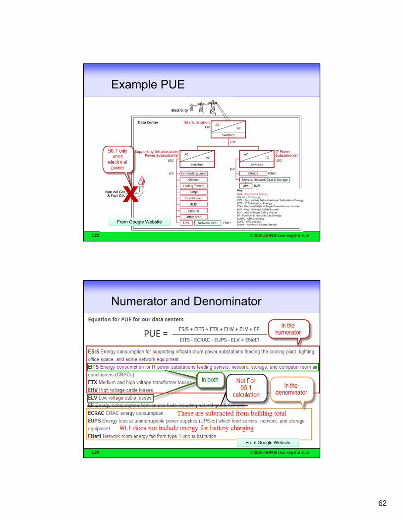
6.5.4 Hydronic System Design and Control
6.5.4.1 Boiler Turndown
6.5.4.2 Hydronic Variable Flow Systems
6.5.4.3 Chiller and Boiler Isolation
6.5.4.4 Chilled- and Hot-Water Temperature Reset Controls
6.5.4.5 Hydronic (Water Loop) Heat Pumps and Water-Cooled Unitary Air Conditioners
6.5.4.6 Pipe Sizing

52
103 © 2016 ASHRAE Learning Institute
6.5.4.1 Boiler Turndown
The system turndown requirement shall be met through the use of multiple single-input boilers, one or more modulating boilers, or a combination of single-input and modulating boilers.
104 © 2016 ASHRAE Learning Institute
HVAC Prescriptive Section 6.5.4Hydronic System Design and Control
• 6.5.4.2 Variable flow required for systems• >10 total hp• More than 3 control valves• Modulate to <50% design flow• Except systems requiring constant flow that have pump system power
<75 hp• Requires an auto shut-off valve at each heat pump on a loop with total
system pump power over 10 hp
• Individual chilled water pumps• 5 hp motor
• 30% design wattage at 50% flow
• Controlled as a function of flow or pressure differential at end of system with setpoint not more than 110% of critical circuit pressure drop
• Or with DDC a function of Valve position

53
105 © 2016 ASHRAE Learning Institute
HVAC Prescriptive Section 6.5.4Hydronic System Design and Control
• 6.5.4.3 Pump isolation– Corresponding flow reduction must occur when chiller or
boiler is shut down
– Series chillers considered as one chiller
– Chillers and boilers with constant speed pumps on headers shall have no less than same number pumps as the chillers
• 6.5.4.4 Chilled and hot water reset based on load indicator
– Exceptions:
• <300,000 Btu/h
• Result in improper operation
• Variable flow systems
106 © 2016 ASHRAE Learning Institute
6.5.4.5 Hydronic (Water Loop) Heat Pumps and Water-Cooled Unitary
• Water source heat pumps and unitary water cooled equipment shall have a 2-position valve to shut off water flow when the compressor is off• Exception: Units with water economizers
6.5.4.5.1
• Pumps >5 HP shall be controlled to have no more than 30% wattage at 50% flow6.5.4.5.2

54
107 © 2016 ASHRAE Learning Institute
6.5.4.6 Pipe Sizing
108 © 2016 ASHRAE Learning Institute
6.5.5 Heat Rejection Equipment
Fans over 7.5 HP Reduce to 2/3speed or less
Automatically change speeds to
control leaving temperature
Above not required in Climate Zones 1
& 2, or for some condenser systems
Multi-cell towers run all the fans you can and all at the same
speed
Do not use centrifugal fans on open towers over 1100 GPM unless
ducted
Towers must turn down to handle the smallest pump or 50% design flow

55
109 © 2016 ASHRAE Learning Institute
6.5.6 Energy Recovery
Many Exceptions, including heating in Zones 1 and 2; cooling in Zones 3c, 4c, 5b, 5c, 6b, 7 and 8; and any system that has less than 75% of the exhaust at a single location
110 © 2016 ASHRAE Learning Institute
6.5.6 Energy Recovery
Many Exceptions, including heating in Zones 1 and 2; cooling in Zones 3c, 4c, 5b, 5c, 6b, 7 and 8; and any system that has less than 75% of the exhaust at a single location

56
111 © 2016 ASHRAE Learning Institute
HVAC Prescriptive Section 6.5.6 Energy Recovery
6.5.6.2 Condenser Heat Recovery for Service Water Heating– 24 hrs per day
– Heat rejection >6 MMBtu/h
– SWH load >1 MMBtu/h
– Must provide smaller of 60% of heat rejection or preheat peak service hot water to 850F
– Exceptions for heat recovery and solar energy
112 © 2016 ASHRAE Learning Institute
HVAC Prescriptive Section 6.5.7 Exhaust Hoods

57
113 © 2016 ASHRAE Learning Institute
6.5.7.1.4 Kitchen Dining facility
Total kitchen hood exhaust airflow rate greater than 5000 cfm, then it shall be option 1: At least 50% of all replacement air is transfer air that would otherwise be exhausted.
114 © 2016 ASHRAE Learning Institute
Maximum Exhaust of Kitchen Hoods
6.5.7.1.5 Performance Testing. An approved field test method shall be used to evaluate design airflow rates and demonstrate proper capture and containment performance of installed commercial kitchen exhaust systems. Where demand ventilation systems are utilized to meet Section 6.5.7.1.4, additional performance testing shall be required to demonstrate proper capture and containment at minimum airflow.

58
115 © 2016 ASHRAE Learning Institute
Laboratory Exhaust Systems
116 © 2016 ASHRAE Learning Institute
HVAC Prescriptive Section 6.5.8 Radiant Heat• 6.5.8.1 Radiant Heating required for heating
unenclosed spaces– Except loading docks with air curtains
• 6.5.8.2 Radiant Heating in enclosed spaces must comply with the standard

59
117 © 2016 ASHRAE Learning Institute
HVAC Prescriptive Section 6.5.9 Hot Gas Bypass Limitation
– Table for VAV and single zone VAV units, hot gas bypass is not allowed on constant-volume units
– Multiple steps or continuous unloading with hot gas initiated only after unloading to:
Rated Capacity Maximum Hot Gas Bypass Capacity (% of Total Capacity)
240,000 Btu/h (70 kW) 15%
> 240,000 Btu/h (70 kW) 10%
Total Unit Capacity Unloaded down to before bypass
118 © 2016 ASHRAE Learning Institute
6.5.10 Door Switches
Any conditioned space with a door
Cooling: Reset setpoint to ≥ 90ºF≤ 5 min of opening or disable cooling
Heating: Reset setpoint to ≤ 55ºF≤ 5 min of opening or disable heating

60
119 © 2016 ASHRAE Learning Institute
6.5.11 Refrigeration Systems
Condensers
• Condensing tempera-ture tied to design DB temperature
• ECM motors• Variable setpoint control• Control fans in unison• Minimum condensing
temperature ≤ 70ºF
Compressors
• Floating suction pressure control
• Liquid subcooling• Cycle off crankcase
heaters
Refrigeration Systems
120 © 2016 ASHRAE Learning Institute
6.6 Alternate Compliance Path
6.6.1 Computer Room Systems: New Metric
• power usage effectiveness (PUE): computer room energy divided by IT equipment energy calculated in accordance with industry-accepted standards (see Informative Appendix E).
• power usage effectiveness—category 0 (PUE0): peak electric demand (kW) for the entire computer room, including IT equipment and supporting infrastructure, divided by peak electric demand (kW) of the IT equipment.
• power usage effectiveness—category 1 (PUE1): annual energy consumption (kWh) for the entire computer room, including IT equipment and supporting infrastructure, divided by annual energy consumption (kWh) of the IT equipment.

61
121 © 2016 ASHRAE Learning Institute
Table 6.6.1 – PUE
122 © 2016 ASHRAE Learning Institute
6.6.1.1 Alternate Path
• Computer rooms must comply with 6.4 – mandatory
• Show that the annual kWh use PUE1 is below the maximum in Table 6.6.1
• Show that the 50% design kW PUE0 is below the maximum in Table 6.6.1
• Show that the 100% design kW PUE0 is below the maximum in Table 6.6.1
62
123 © 2016 ASHRAE Learning Institute
Example PUE
From Google Website
124 © 2016 ASHRAE Learning Institute
Numerator and Denominator
From Google Website

63
125 © 2016 ASHRAE Learning Institute
6.7 Submittals
• 6.7.1 AHJ may require compliance documentation 4.2.2
• Completion Requirements are mandatory
• 6.7.2 Completion Requirements– 6.7.2.1 Drawings
– 6.7.2.2 Manuals
– 6.7.2.3 System Balancing• 6.7.2.3.1 General
• 6.7.2.3.2 Air System Balancing
• 6.7.2.3.3 Hydronic System Balancing
• 6.7.2.4 System Commissioning
Trim impellers or change speed on pumps larger than 10 hp when throttling of pump is greater than 5% of nameplate hp or 3 hp
126 © 2016 ASHRAE Learning Institute
OTHER EQUIPMENTSection 10
64
127 © 2016 ASHRAE Learning Institute
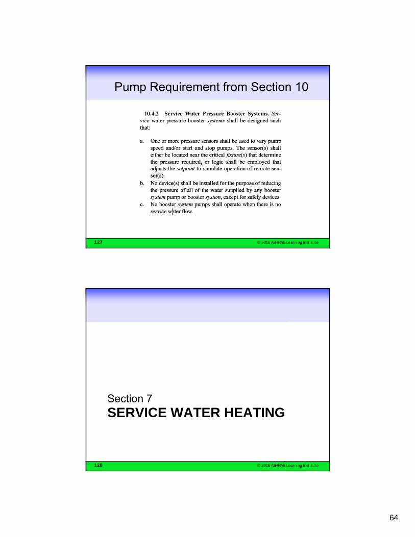
Pump Requirement from Section 10
128 © 2016 ASHRAE Learning Institute
SERVICE WATER HEATINGSection 7

65
129 © 2016 ASHRAE Learning Institute
SWH Section 7Compliance Path
130 © 2016 ASHRAE Learning Institute
Requirements for RecirculationSystems and Remote Heaters

66
131 © 2016 ASHRAE Learning Institute
SWH Mandatory Section 7.4.1 SWH Load Calculations
• Must be performed
• Manufacturer’s published methods or generally acceptable design practice in publications (e.g., ASHRAE Handbook-Applications)
132 © 2016 ASHRAE Learning Institute
SWH Mandatory Section 7.4.2SWH Equipment Efficiency Table 7.8
Equipment Type Size Category Sub-Category or Rating Condition
Performance Required 9/1/2001c
Test Procedurea
Electric Water Heaters
12 kW Resistance 0.93-0.00132V EF DOE 10 CFR Part 430
> 12 kW Resistance 20 + 35V SL, Btu/h ANSI Z21.10.3 24 Amps and
250 Volts Heat Pump 0.93-0.00132V EF DOE 10 CFR
Part 430
Gas Storage Water Heaters
75,000 Btu/h 20 gal 0.62-0.0019V EF DOE 10 CFR Part 430
> 75,000 Btu/h and 155,000 Btu/h
< 4,000 Btu/h/gal 80% Et (Q/800 + 110V)
SL, Btu/h
ANSI Z21.10.3
Gas Instantaneous Water Heaters
50,000 Btu/h and 200,000 Btu/h
4,000 Btu/h/gal and 2 gal
0.62-0.0019V EF DOE 10 CFR Part 430
> 200,000 Btu/hd 4,000 Btu/h/gal and < 10 gal
80% Et ANSI Z21.10.3
> 200,000 Btu/hd 4,000 Btu/h/gal and 10 gal
80% Et (Q/800 + 110V)
SL, Btu/h

67
133 © 2016 ASHRAE Learning Institute
SWH Mandatory Section 7.4.2SWH Equipment Efficiency
• Hot water supply boilers and water heaters must meet standby loss requirements
• Except where they have 140 gal of storage and all of the following:
– Tank insulation to R-12.5
– No standing pilot
– Fuel-fired heaters have flue damper or fan-assisted combustion
134 © 2016 ASHRAE Learning Institute
SWH Mandatory Section 7.4.3SWH Insulation
Insulation to the Table 6.8.3 (HVAC table) required for the following:
– Recirculation system piping including the pipe between a tank and separate heater
– 8 ft of outlet piping from the tank of a storage type non-recirculating system
– Inlet piping between the tank and heat trap on a storage type non-recirculating system
– Externally heated pipes (e.g., heat trace)
68
135 © 2016 ASHRAE Learning Institute
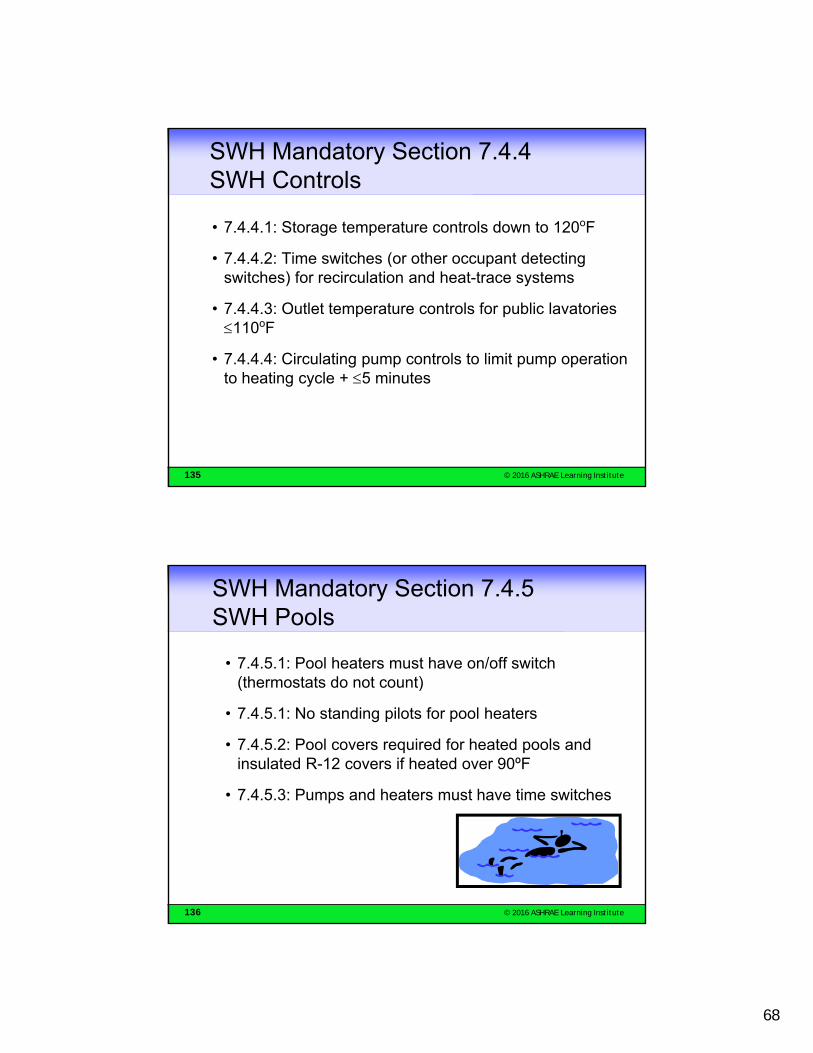
SWH Mandatory Section 7.4.4 SWH Controls
• 7.4.4.1: Storage temperature controls down to 120oF
• 7.4.4.2: Time switches (or other occupant detecting switches) for recirculation and heat-trace systems
• 7.4.4.3: Outlet temperature controls for public lavatories 110oF
• 7.4.4.4: Circulating pump controls to limit pump operation to heating cycle + 5 minutes
136 © 2016 ASHRAE Learning Institute
SWH Mandatory Section 7.4.5 SWH Pools
• 7.4.5.1: Pool heaters must have on/off switch (thermostats do not count)
• 7.4.5.1: No standing pilots for pool heaters
• 7.4.5.2: Pool covers required for heated pools and insulated R-12 covers if heated over 90ºF
• 7.4.5.3: Pumps and heaters must have time switches
69
137 © 2016 ASHRAE Learning Institute
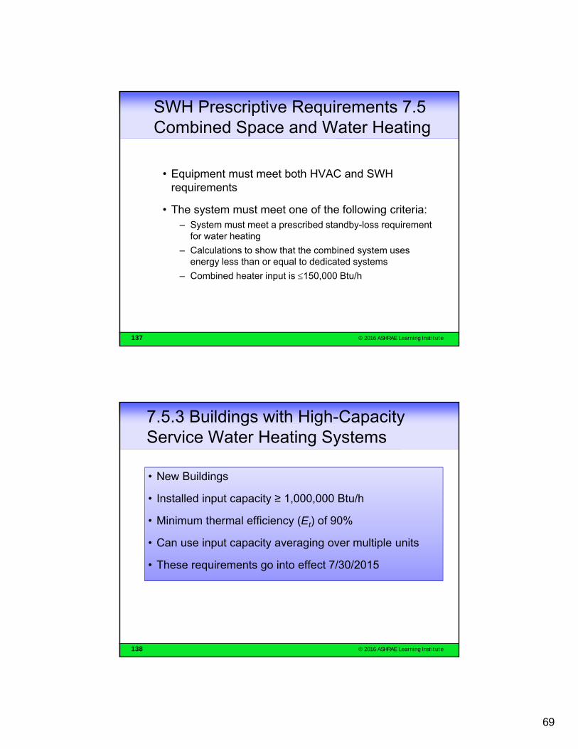
SWH Prescriptive Requirements 7.5 Combined Space and Water Heating
• Equipment must meet both HVAC and SWH requirements
• The system must meet one of the following criteria:– System must meet a prescribed standby-loss requirement
for water heating
– Calculations to show that the combined system uses energy less than or equal to dedicated systems
– Combined heater input is 150,000 Btu/h
138 © 2016 ASHRAE Learning Institute
7.5.3 Buildings with High-Capacity Service Water Heating Systems
• New Buildings
• Installed input capacity ≥ 1,000,000 Btu/h
• Minimum thermal efficiency (Et) of 90%
• Can use input capacity averaging over multiple units
• These requirements go into effect 7/30/2015

70
139 © 2016 ASHRAE Learning Institute
HVAC Section 6.3 Simplified Approach
• Purpose– To ease complexity and compliance burden for 80% of building
permits
• Consistent with prescriptive requirements
• Fits on two pages– Compliance form is 1 page
• 6.3.1 Limited to …– Buildings with 1 or 2 stories
– Buildings less than 25,000 ft2
– Single-zone systems
– Air-cooled or evaporatively-cooled condenser
140 © 2016 ASHRAE Learning Institute
Simple Building Example
• Existing warehouse/office
• Warehouse unconditioned (no heat or cool)
• Office has gas-electric AC unit
• Modified to expand offices and to convert warehouse into a training room, storage and office

71
141 © 2016 ASHRAE Learning Institute
Existing Conditions
142 © 2016 ASHRAE Learning Institute
Proposed Retrofit

72
143 © 2016 ASHRAE Learning Institute
Mechanical Systems
144 © 2016 ASHRAE Learning Institute
Do the New HVAC Systems & Equipment Have to Comply?
“4.1.1.5 Changes in Space Conditioning. Whenever unconditioned or semi-heated spaces in a building are converted to conditioned spaces, such conditioned spaces shall be brought into compliance with all applicable requirements of this standard that would apply to the building envelope, heating, ventilating, air-conditioning, service water heating, power, lighting, and other systems and equipment of the space as if the building were new.”
Conclusion: New systems and equipment must comply.

73
145 © 2016 ASHRAE Learning Institute
Does the Existing HVAC SystemHave to be Upgraded?
“Compliance shall not be required for equipment that is being modified or repaired but not replaced, provided that such modifications and/or repairs will not result in an increase in the annual energy consumption of the equipment…” (6.1.1.3 Exception a)
Conclusion: Existing unit, including thermostat and other controls, need not be upgraded and may be repaired without invoking full compliance provided the repairs do not increase energy use.
146 © 2016 ASHRAE Learning Institute
Can the Existing System Be Used to Condition Newly Conditioned Space?
When HVAC or service water heating to an addition is provided by existing HVAC or service water heating systems and equipment:
–Such existing systems and equipment shall not be required to comply with this standard.
–However, any new systems or equipment installed must comply with specific requirements applicable to those systems and equipment. (6.1.1.3)
Conclusion: Existing system may be used to condition new space, but any new equipment must meet the Standard (for example, new duct must be insulated)

74
147 © 2016 ASHRAE Learning Institute
New Systems & Equipment Must Comply
148 © 2016 ASHRAE Learning Institute
HVAC Equipment Efficiency
• HP-1: Split Heat Pump <65,000 Btu/h Cooling: 13 SEERHeating: 7.7 HSPF
• AC-2: Gas/Electric AC >65,000 <135,000 Btu/hCooling: 11 EER – 11.2 IEERHeating: <225,000 Btu/h
78% AFUE or 80% Et
• EWH-1: Electric resistance wall heaterNo requirement

75
149 © 2016 ASHRAE Learning Institute
Simplified Approach 6.3.1 Economizer Requirements
• Not required for existing AC unit (AC-1); existing equipment need not be upgraded
• Not required for split system heat pump for office (HP-1); less than 54,000 Btu/h
• Required for training room AC system (AC-2); larger than 90,000 >54,000 Btu/h
150 © 2016 ASHRAE Learning Institute
Simplified Approach 6.3.2
6.3.2 Criteria. The HVAC system must meet all of the following criteria:
a. The system serves a single HVAC zone.
b. The equipment must meet the variable flow requirements of Section 6.5.3.2.1.
c. Cooling (if any) shall be provided by a unitary packaged or split-system air conditioner that is either air cooled or evaporatively cooled, with efficiency meeting the requirements shown in Table 6.8.1-1 (air conditioners), Table 6.8.1-2 (heat pumps), or Table 6.8.1-4 (packaged terminal and room air conditioners and heat pumps) for the applicable equipment category.

76
151 © 2016 ASHRAE Learning Institute
Simplified Approach 6.3.2
d. The system shall have an air economizer meeting the requirements of Section 6.5.1.
e. Heating (if any) shall be provided by a unitary packaged or split-system heat pump that meets the applicable efficiency requirements shown in Table 6.8.1-2 (heat pumps) or Table 6.8.1-4 (packaged terminal and room air conditioners and heat pumps), a fuel-fired furnace that meets the applicable efficiency requirements shown in Table 6.8.1-5 (furnaces, duct furnaces, and unit heaters), an electric resistance heater, or a baseboard system connected to a boiler that meets the applicable efficiency requirements shown in Table 6.8.1-6 (boilers).
f. The system shall meet the exhaust air energy recovery requirements of Section 6.5.6.1
g. The system shall be controlled by a manual changeover or dual setpoint thermostat.
152 © 2016 ASHRAE Learning Institute
Simplified Approach 6.3.2
h. If a heat pump equipped with auxiliary internal electric resistance heaters is installed, controls shall be provided that prevent supplemental heater operation when the heating load can be met by the heat pump alone during both steady-state operation and setback recovery. Supplemental heater operation is permitted during outdoor coil defrost cycles. The heat pump must be controlled by either: (1) a digital or electronic thermostat designed for heat-pump use that energizes auxiliary heat only when the heat pump has insufficient capacity to maintain setpoint or to warm up the space at a sufficient rate; or (2) a multi-stage space thermostat and an outdoor air thermostat wired to energize auxiliary heat only on the last stage of the space thermostat and when outdoor air temperature is less than 40oF.
i. The system controls shall not permit reheat or any other form of simultaneous heating and cooling for humidity control.
77
153 © 2016 ASHRAE Learning Institute
Simplified Approach 6.3.2
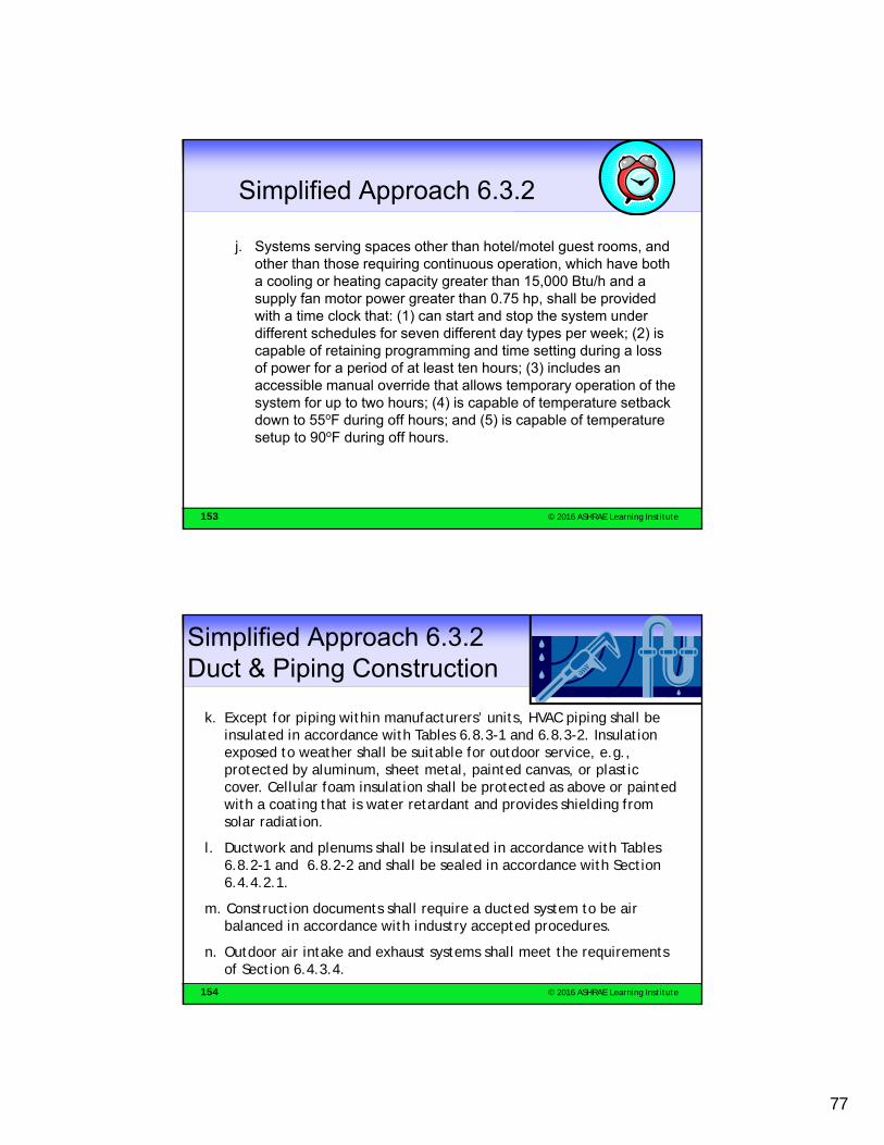
j. Systems serving spaces other than hotel/motel guest rooms, and other than those requiring continuous operation, which have both a cooling or heating capacity greater than 15,000 Btu/h and a supply fan motor power greater than 0.75 hp, shall be provided with a time clock that: (1) can start and stop the system under different schedules for seven different day types per week; (2) is capable of retaining programming and time setting during a loss of power for a period of at least ten hours; (3) includes an accessible manual override that allows temporary operation of the system for up to two hours; (4) is capable of temperature setback down to 55oF during off hours; and (5) is capable of temperature setup to 90oF during off hours.
154 © 2016 ASHRAE Learning Institute
Simplified Approach 6.3.2Duct & Piping Construction
k. Except for piping within manufacturers’ units, HVAC piping shall be insulated in accordance with Tables 6.8.3-1 and 6.8.3-2. Insulation exposed to weather shall be suitable for outdoor service, e.g., protected by aluminum, sheet metal, painted canvas, or plastic cover. Cellular foam insulation shall be protected as above or painted with a coating that is water retardant and provides shielding from solar radiation.
l. Ductwork and plenums shall be insulated in accordance with Tables 6.8.2-1 and 6.8.2-2 and shall be sealed in accordance with Section 6.4.4.2.1.
m. Construction documents shall require a ducted system to be air balanced in accordance with industry accepted procedures.
n. Outdoor air intake and exhaust systems shall meet the requirements of Section 6.4.3.4.

78
155 © 2016 ASHRAE Learning Institute
Simplified Approach 6.3.2
o. Where separate heating and cooling equipment serves the same temperature zone, thermostats shall be interlocked to prevent simultaneous heating and cooling.
p. Systems with a design supply air capacity greater than 10,000 cfm shall have optimum start controls.
q. The system shall comply with the demand control ventilation requirements in Section 6.4.3.8.
r. The system complies with the door switch requirements in Section 6.5.10.
156 © 2016 ASHRAE Learning Institute
THANK YOU!
ANY QUESTIONS?Mack Wallace

79
157 © 2016 ASHRAE Learning Institute
Evaluation & Certificate
• ASHRAE values your comments about this course. You will receive your Certificate of Attendance when you complete the online course evaluation at this URL: http://ali.ashrae.biz/2016fallonline/Access code: h6w2Be sure to add your appropriate license numbers.
• If you have questions about ASHRAE Certificates, please contact Kelly Arnold, Administrative Assistant, at [email protected]
• If you have questions about ASHRAE courses, please contact Martin Kraft, Managing Editor, at [email protected]
158 © 2016 ASHRAE Learning Institute
ASHRAE Career Enhancement Curriculum Program
Expand your knowledge of IAQ and Energy Savings Practices through a select series of ASHRAE Learning Institute courses
• Receive up-to-date instruction on new technology from industry experts
• Gain valuable HVAC knowledge
• Accelerate your career growth
• Receive a certificate for successful completion of the course series
Visit www.ashrae.org/careerpath to learn more.

80
159 © 2016 ASHRAE Learning Institute
ASHRAE Professional Certification
ASHRAE has certified more than 2,200 professionals Gain a competitive edge by earning an ASHRAE certification
Demonstrate competency in critical job knowledge, skills and abilities
Elevate your reputation among peers, in the workplace and among clients
Comply with local, state and federal requirements
Visit www.ashrae.org/certification to learn more about these 6 programs: Building Energy Assessment Professional (BEAP)
Building Energy Modeling Professional (BEMP)
Commissioning Process Management Professional (CPMP)
Healthcare Facility Design Professional (HFDP)
High-Performance Building Design Professional (HBDP)
Operations & Performance Management Professional (OPMP)