Compliant Culture Platforms with Independently Tunable ...
86
University of New Mexico UNM Digital Repository Electrical and Computer Engineering ETDs Engineering ETDs Fall 12-10-2016 Compliant Culture Platforms with Independently Tunable Stiffness and Electrical/Optical Functionality Nadeem Abdul University of New Mexico - Main Campus Follow this and additional works at: hps://digitalrepository.unm.edu/ece_etds Part of the Electrical and Computer Engineering Commons is esis is brought to you for free and open access by the Engineering ETDs at UNM Digital Repository. It has been accepted for inclusion in Electrical and Computer Engineering ETDs by an authorized administrator of UNM Digital Repository. For more information, please contact [email protected]. Recommended Citation Abdul, Nadeem. "Compliant Culture Platforms with Independently Tunable Stiffness and Electrical/Optical Functionality." (2016). hps://digitalrepository.unm.edu/ece_etds/297
Transcript of Compliant Culture Platforms with Independently Tunable ...

University of New MexicoUNM Digital Repository
Electrical and Computer Engineering ETDs Engineering ETDs
Fall 12-10-2016
Compliant Culture Platforms with IndependentlyTunable Stiffness and Electrical/OpticalFunctionalityNadeem AbdulUniversity of New Mexico - Main Campus
Follow this and additional works at: https://digitalrepository.unm.edu/ece_etds
Part of the Electrical and Computer Engineering Commons
This Thesis is brought to you for free and open access by the Engineering ETDs at UNM Digital Repository. It has been accepted for inclusion inElectrical and Computer Engineering ETDs by an authorized administrator of UNM Digital Repository. For more information, please [email protected].
Recommended CitationAbdul, Nadeem. "Compliant Culture Platforms with Independently Tunable Stiffness and Electrical/Optical Functionality." (2016).https://digitalrepository.unm.edu/ece_etds/297

i
NADEEM ABDUL
Candidate
Electrical and Computer Engineering (ECE)
Department
This thesis is approved, and it is acceptable in quality and form for publication:
Approved by the Thesis Committee
Dr. Francesca Cavallo, Chairperson
Dr. Andrew P. Shreve
Dr. Mani Hossein-Zadeh
ii
Compliant Culture Platforms with Independently
Tunable Stiffness and Electrical/Optical Functionality
by
Nadeem Abdul
B.E., Electrical Engineering, Osmania University, 2013
THESIS
Submitted in partial fulfilment of
Requirements for the Degree of
Master of Science
Electrical Engineering
at
The University of New Mexico
Albuquerque, New Mexico
December, 2016

iii
Dedicated to Dr. Francesca Cavallo.

iv
Compliant Culture Platforms with Independently
Tunable Stiffness and Electrical/Optical Functionality
by
Nadeem Abdul.
B.E., Electrical Engineering, Osmania University, 2013
M.S., Electrical Engineering, University of New Mexico, 2016
ABSTRACT
Interfacing biological cells and solid-state devices is crucial in many applications,
ranging from well-established fields, such as electrophisiology, to the newly
developed areas of optogenetics and mechanobiology. Most biological cells are
anchored to substrates with elastic modulus, E, in the range of ~1 to 100 kPa, the
moduli of brain-tissue and osteoid, respectively. On the other hand, bulk
semiconductor substrates have ~6 orders of magnitude higher elastic modulus. This
large elastic mismatch between devices and cells natural microenvironments is an
issue for bio-devices integration, as cells are highly sensitive to mechanical cues.
Specifically, cells exert traction forces on their surroundings and adjust their
adhesion mechanism, cytoskeleton, locomotion and overall state according to the
stiffness of the substrate they are anchored to. This type of behavior makes it a
significant challenge to integrate semiconductor devices with biological cells
without altering the cell state.
I demonstrate a new family of culture platforms to successfully integrate
biological cells and electronic/photonic devices from a mechanical perspective.
The proposed platforms are referred to as effectively compliant layered substrates
(ECLS). ECLS are based on inorganic nanomembranes (NMs) partially suspended

v
or bonded to compliant substrates. The unique attribute of ECLS is that, the
constitutive material of the NM provides the electrical and optical functionality
necessary to a device operation, while the NM geometry and the nature of the
supporting substrate can be tailored to match the mechanical response of biological
tissues. Specifically, I present fabrication and bio-interfacing of ECLS comprising
of device-grade, single-crystal Si NMs on a compliant PDMS substrate with
tunable elastic modulus from ~kPa to ~MPa. NMs with thickness in the range of
~20-220 nm and ~ 1x1 cm2 lateral areas are used in this study. ECLS are obtained
using a two-step process, including synthesis of the compliant supporting substrate
and fabrication, release and transfer of the NM onto the compliant host.
Characterization of the mechanical properties of the ECLS and of the bare
compliant substrate is performed by nanoindentation.
Finally, I access a 3T3 fibroblast cell culture on the fabricated ECLS, as well as on
bulk silicon and bare soft substrates to investigate cell response to mechanical
cues. Specifically, I investigate cytotoxicity of ECLS substrate and conduct a
comparative analysis of cell proliferation, morphology, and adhesion mechanisms
between bulk Si, and Si-based ECLS with different elastic moduli. Flow-
cytometry, bright-field and confocal fluorescence microscopy are used for this
study. The proposed ECLS approach has successfully allowed fabrication of
device-graded platforms with varying elastic modulus over three orders of
magnitude and matching the mechanical properties of a wide range of biological
tissues. Fabricated ECLS allowed healthy bioactivity of 3T3 fibroblast with no
toxic behavior. 3T3 fibroblast cultured on ECLS with different elastic modulus
displayed a drastic change in cytoskeleton (size and shape) and adhesion
mechanisms (stress fiber organization and focal adhesions) compared to that of
bulk Si.

vi
Acknowledgements
I would like to thank my advisor Prof. Francesca Cavallo for providing me with the
opportunity to join in her research group. I also would like to thank Francesca for
giving me the freedom to make mistakes, explore, learn and become a more
complete and mature researcher/individual. Experience with you will be one of the
biggest contributions to my career and life in general. You have been an excellent
teacher and the challenge of living up to your standards of excellence was a
rewarding experience. I have benefited greatly from my association with all past
and present members of the Dr. Cavallo’s lab and Grad students at CHTM, in
particular Vijay Saradhi Mangu, Mahmoud Behzadirad, Sami Adnan Nazib, Noel
Dawson, Denies Torres, Aneesha Kondapi, Farhana Anwar, Marziyeh Zamiri
Corey Carlos, and Kenneth Opheim. Interactions with you guys made me a more
complete individual.
I would also like to thank Ali Nematollahisarvestani and Prof. Mehran Tehrani
from mechanical engineering department for their valuable contribution in this
work. A simple thank you is insufficient for Matthew Rush, as he was my mentor
in an unknown realm of tissue culture study, without him I would not have
accomplished nearly as much in this thesis. I am grateful to Dr. Andrew P. Shreve
for providing us with his brightest student and also for his timely critical
assessment of proof of plan in tissue culture study.
Last but not least, I would like to thank all staff of CHTM cleanroom and students
from CBME, who saved me tremendous amount of time in many experiment by
providing timely troubleshoots, tweaks and tricks. Finally, I would like to thank
my family and friends for their unconditional support and love.

vii
Table of Content
ABSTACT ............................................................................................................ IV
ACKNOWLEDGEMENTS ............................................................................... VI
TABLE OF CONTENTS .................................................................................... VII
LIST OF TABLES ............................................................................................ VIII
LIST OF FIGURES ............................................................................................. IX
1. Introduction .................................................................................................... 1
2. Experimental Methods ................................................................................. 7
2.1. Fabrication of the effectively compliant layered substrates (ECLS) .... 7
2.1.1. Compliant substrate: Polydimethylsiloxane (PDMS) ....................... 7
2.1.2. PDMS modification ................................................................................... 10
2.1.3. Nano membrane (NM) fabrication and integration with the
compliant host .............................................................................................. 13
2.2. Characterization of the effectively compliant layered substrates ...... 21
2.2.1. Contact angle measurements ................................................................... 21
2.2.2. Nano indentation ......................................................................................... 22
2.3. In vitro study: cell culture and cell characterization methods ............. 25
2.3.1. Cell culture .................................................................................................. 25
2.3.2. Cell characterization: Flow cytometry ................................................. 27
2.3.3. Cell characterization: Immunofluorescent staining .......................... 28
3. Results: ECLS fabrication and characterizations ................................... 30
3.1. Rationale for ECLS approach. ............................................................ 30
3.2. Compliant substrates: with tunable mechanical properties: ............. 34
3.2.1. Elastic modulus of various formulations ......................................... 38
3.2.2. Modified PDMS ............................................................................. 40
3.3. Various ECLS and rational ................................................................ 44
3.3.1. Elastic modulus of ECLS ............................................................... 48
4. In vitro study of cell response on ECLS ................................................... 52
4.1. Introduction: 3T3 Fibroblasts .............................................................. 52
4.2. In vitro study ...................................................................................... 55
Results: Cell viability and cell proliferation using flow cytometry
Results: Actin Cytoskeleton and Focal Adhesion:
5. Summary and Future directions ................................................................ 64
Reference ...................................................................................................................................... 68

viii
LIST OF TABLES
Table 2.1: Photolithographic process used to transfer a pattern on to the photoresist
surface. .................................................................................................................................................. 15
Table 3.1: Formulations of different PDMS investigated in this study. ..................... 36
Table 3.2: Elastic modulus of various Formulations PDMS investigated in this
study. ...................................................................................................................................................... 39
Table 3.3: Near surface mechanical properties of ECLS samples from low load
indentation with a conospherical probe with a 5μm tip radius. ..................................... 49
Table 4.1: Summary of various response of 3T3 fibroblast to substrate with
decreasing elastic modulus. .......................................................................................................... 54
Table 4.2: Summary of substrates used in In vitro study ................................................... 55

ix
LIST OF FIGURES
Figure 1.1: Shows several examples of electronic devices for in vivo applications.
...................................................................................................................................................................... 1
Figure.1.2: Schematic illustrates change in cell behavior due microenvironment
stimuli. ...................................................................................................................................................... 3
Figure 1.3: Capture substrate anchored cell behavior studied in literature. ................. 3
Figure 1.4: a) biological cells anchoring elastic modulus in their native
environment b) highlights the existing mismatch between cell-device mechanical
environments. ........................................................................................................................................ 4
Figure 2.1: Process steps to obtain hybrid PDMS substrates. ............................................ 8
Figure 2.2: Setup for soxhlet extraction. ................................................................................. 11
Figure 2.3: Surface termination of PDMS before (left) and after UVO treatment
(right) ..................................................................................................................................................... 12
Figure 2.4: SOI multilayered structure. ................................................................................... 13
Figure 2.5: Schematic illustration of Si thinning via thermal oxidation and
subsequent oxide removal. ............................................................................................................ 14
Figure 2.6: Schematic illustration of photolithography and RIE. ................................. 16
Figure 2.7: Schematic illustration of silicon nanomembrane release from SOI
wafer. ..................................................................................................................................................... 17
Figure 2.8: Schematic illustration of release and wet transfer of a NM onto a host
substrate ................................................................................................................................................. 19
Figure 2.9: Wet transfer of NM using a wire formed into a loop. ................................ 19
Figure 2.10: Schematic illustration of the release and dry transfer of a NM using a
stamp ....................................................................................................................................................... 21
x
Figure 2.11: Schematic illustration of a hydrophobic surface, θ ≥ 90° (left) and a
hydrophilic surface, θ ≤ 90° (right) ........................................................................................... 21
Figure 2.12: Schematic illustration of indentation technique .......................................... 22
Figure 2.13: Schematic illustration of indentation load–displacement data showing
important measured parameters.................................................................................................... 23
Figure 3.1: Stiffness of a plate with rectangular cross-section (k). The relationship
between k, the geometry of the plate and its elastic constants (E, Elastic modulus
and, Poisson’s ratio) is summarized for three different modes of deformation. ..... 31
Figure 3.2: Proposed approach to tune the stiffness of the ECLS. From left to right,
bulk materials are made into NMs and transferred to a compliant host. (NMs are
exceptionally compliant to bending and axial deformation due to their nanoscale
thickness). In addition, NMs are patterned into lateral dimensions matching the
diameter of biological cells and perforated to further reduce their stiffness .............. 32
Figure 3.3: Effective stiffness vs. contact radius as determined by FEA for a rigid,
cylindrical flat punch indenting into three bulk materials with elastic modulus of
10 kPa (Substrate A, red dashed line corresponding roughly to PAAG), 1 MPa
(Substrate B, blue dashed line, corresponding roughly to PDMS), 148 GPa (black
dashed line, corresponding to bulk Si); 25 nm and 100nm SiNMs on substrate A
(red solid diamonds and red open diamonds, respectively); and 25 nm and 100nm
SiNMs on substrate B (blue solid squares and blue open squares, respectively). The
contact radius, a, is the radius of the cylindrical indenter, and the SiNM is assumed
to be perfectly bonded to the PDMS substrate ....................................................................... 33
Figure 3.4: Photographs show a standard 184 PDMS and pure 527 (1:1) fabricated
as per manufacture direction, holding by a tweezer ............................................................. 36
Figure 3.5: Shows force vs displacement plot for a 184(1:10) PDMS; Red curve
indicates loading of AFM tip into PDMS; Blue curve indicates unloading of tip
from the substrate. Bouncy retraction of tip from substrate indicated adhesiveness
of PDMS ................................................................................................................................................ 39
xi
Figure 3.6: Hybrid 1:20 PDMS (12mm diameter) undergoing accelerated solvent
extraction for 3hrs a) swollen PDMS (left) immediately after treatment, b) samples
overnight air dried in fume hood to allow solvent evaporation(right).......................... 40
Figure 3.7: a) Contact angle before solvent extraction on hybrid (1:20), b) Contact
angle after solvent extraction ........................................................................................................ 41
Figure 3.8: UV ozone treatment: exposure time vs hydrophilicity ................................ 42
Figure 3.9: Hydrophobic recovery test a) Contact angle before UV-ozone treatment
on hybrid (1:20), b) Contact angle immediately after UVO treatment, c) Contact
angle after 48hrs in water ................................................................................................................ 43
Figure 3.10: Schematic illustration of ECLS fabrication. ................................................ 44
Figure 3.11: Illustrates schematic and optical microscopic images of a) Large area
supported ECLS (i.e. 1cm2x1cm2 SiNM 220nm on hybrid PDMS (1:10), b) Small
area supported ECLS (3x3 array of SiNM 220nm pixel of size 100μm on standard
PDMS 184 (10:1)) ............................................................................................................................. 45
Figure 3.12: Schematic illustration of edge tethered ECLS fabrication process. ... 46
Figure 3.13: Illustrates schematic and optical microscopic images of a) Large –
area edge tethered ECLS, SiNM 220nm (1cm2 x 1cm2) on standard PDMS 184
(10:1) with 2mm x2mm suspension of 20nm. b) Edge tethered with 100μm
suspension of 20nm array on standard PDMS 184(10:1) .................................................. 47
Figure 3.14: (a) shows an image of 220 nm failed transfer causing wrinkle (b)
20nm SiNM failed transferred with lots of wrinkle, due to lesser thickness (c)
cracks and delamination of 220 nm NM on a PDMS(<100kPa)). ................................ 48
Figure 3.15: Storage modulus with respect to contact depth on 220nm SiNm on
standard (1:10) PDMS and 220nm SiNM on Hybrid (1:10) PDMS with a
conospherical probe with a 5μm tip radius. ........................................................................... 50
Figure 3.16: Overlap of load vs displacement curve of PDMS; 49nm SiNM on
PDMS and 220nm SiNM on PDMS. ........................................................................................ 51

xii
Figure 4.1: Typical 3T3 change in shape and size due to substrates elastic modulus
................................................................................................................................................................... 53
Figure 4.2: Typical 3T3 fibroblast focal adhesion points on a soft and hard
substrate ................................................................................................................................................. 53
Figure 4.3: Bright field optical images of 3T3 fibroblast cultured in vitro on a
fabricated specimen including a 220 nm Si NM/PDMS. The Si NM is perforated
with an array of 2D holes. The images were acquired using an inverted microscope
over (1-5) days in vitro (DIV). The images clearly show a healthy proliferation of
the cells on investigated surfaces over the course of study, thereby confirming the
viability of 3T3 fibroblasts on the fabricated specimens. .................................................. 56
Figure 4.4: Living cell population of 3T3 fibroblast at four specific time periods; if
a substrate reads 70% or more living cells, substrate is considered to be
biocompatible ...................................................................................................................................... 58
Figure 4.5: Growth curve associated with three different samples with drastic
change in elastic modulus; SiNM/PDMS (approx. 160kpa); bare PDMS (approx.
80kPa) and bare silicon (approx. 164 Gpa). Number of viable cells stained with
CyQuant Direct Cell Proliferation assay measured with flow cytometer ................... 59
Figure 4.6: Illustrate 3T3 fibroblast change in size, shape and orientation with
respective mechanical properties of substrate. a) bulk silicon (in Gpa range). b)
hard ECLS composed of SiNM 220nm on PDMS hybrid (1:20), elastic modulus
approx. 160kPa c) soft ECLS with Si NM 20nm on hybrid PDMS (1:10) elastic
modulus approx. 80kpa. ................................................................................................................. 61
Figure 4.7: Single cell focal attachment points and F- actin fiber organization on
substrates with different mechanical properties. a) 3T3 fibroblast on bare silicon
wafer (Elastic modulus approx. 15Gpa) b) hard ECLS composed of SiNM 220nm
on PDMS hybrid (1:20), elastic modulus approx. 160kPa c) At the boundary of Si
220nm and hybrid PDMS (1:20), elastic modulus approx. 160kpa and 80kPa,
respectively d) soft ECLS with Si NM 20nm on hybrid PDMS (1:10) elastic
modulus approx. 80kpa. ................................................................................................................. 62

xiii
Figure 5.1: Hall bar fabrication, release and transfer on the compliant substrate.
Hall bars are fabricated on the unreleased NM by conventional top-down
processing techniques (a)-(b). A support layer is spun onto the fabricate device (c)
to provide mechanical stability during release and transfer to the compliant host
(d). The support layer is finally cleaned by solvents (e). .................................................. 66
Figure 5.2: a) Groove like 3D microstructure on ECLS. b) Buckle like 3D
microstructure on ECLS .................................................................................................................. 67
1
Chapter 1: Introduction
Bio-device integration
Interfacing solid-state devices and biological entities has enabled a great deal of
progress in biomedical science and healthcare since Galvani's first discovery that
nerves and muscles could be electrically stimulated (1760s). Pacemakers,
neuromodulators, electrophysiology, and cochlear implants are only a few
examples signifying the tremendous impact of bio-device integration on our
quality of life. Miniaturization of inorganic materials and solid-state devices has
further extended the scope of electronics, opto-electronics, and photonics towards
bio-applications. As a result, a variety of micro- and nanoscale devices are
increasingly being used for therapy-delivery, diagnostics, prosthetics, fundamental
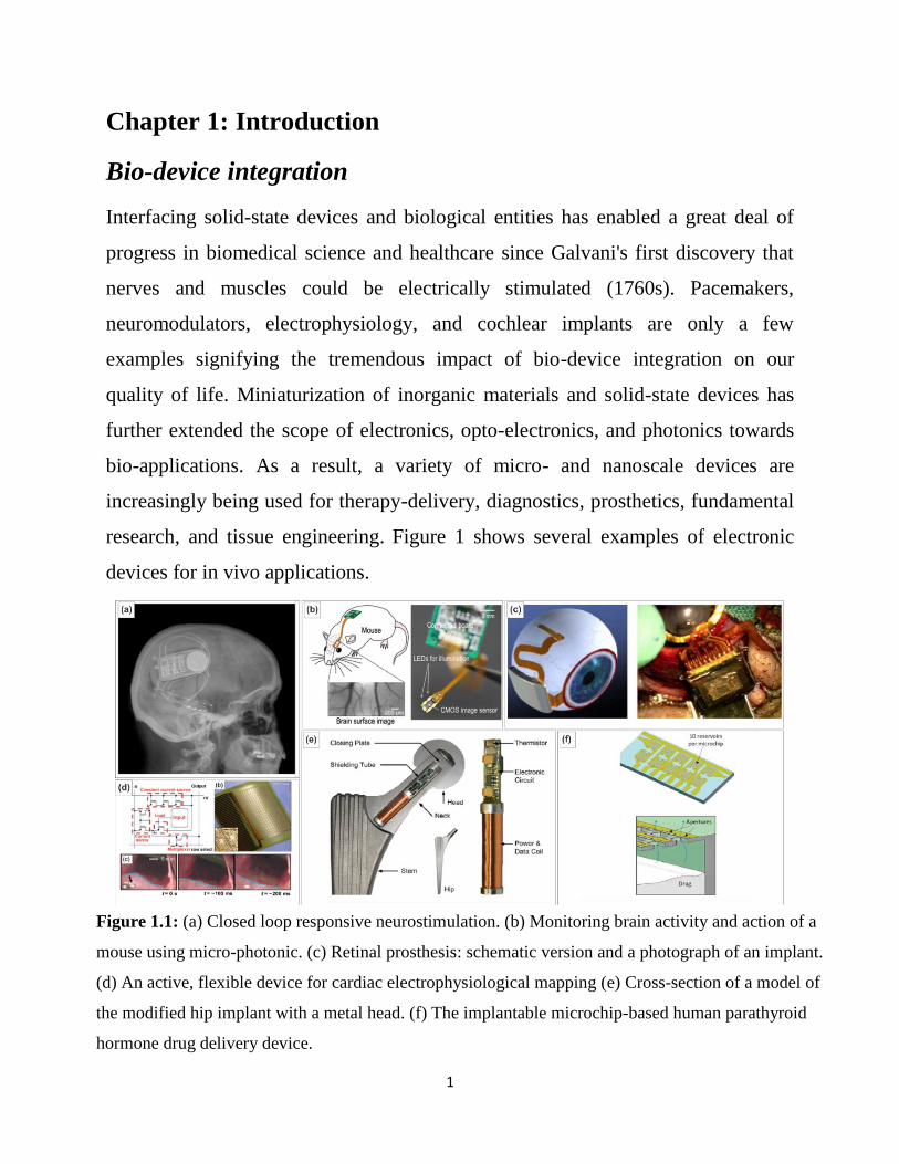
research, and tissue engineering. Figure 1 shows several examples of electronic
devices for in vivo applications.
Figure 1.1: (a) Closed loop responsive neurostimulation. (b) Monitoring brain activity and action of a
mouse using micro-photonic. (c) Retinal prosthesis: schematic version and a photograph of an implant.
(d) An active, flexible device for cardiac electrophysiological mapping (e) Cross-section of a model of
the modified hip implant with a metal head. (f) The implantable microchip-based human parathyroid
hormone drug delivery device.

2
Despite the recent advancement in Micro-electro-mechanical systems (MEMS) and
microfluidic lab-on-chip biomedical systems for development of devices for rapid
diagnostics, and precisely controlled delivery of drugs and complex therapeutics, a
successful bio-device integration still face various challenges related to interfacing
biological entities and device designs. Biological cells are extremely sensitive to
their microenvironment; an implanted device with chemically harsh environment
can result in change in growth factors and cell state. On the other end of spectrum,
the bio degradation of implanted device and its by-products may stimulate
activation of a range of immune mechanisms, leading to inflammation, toxic leach
out which further hinder the recovery of damaged tissues. Surface fouling and
infections are also of great concern. Biological cells not only respond to chemical
microenvironment, but they are also capable of detecting dissimilar mechanical
surrounding from that of their own. By process of mechanotransduction, the
mechanical stimuli are detected and transferred as chemical signals that cells can
process and respond to. Mechanical mismatch between biological tissue and device
material has shown to affect the inflammatory response of biological tissues. In an
attempt to remove the foreign body, cells release a host of chemical and biological
factors that contribute to localized cell degeneration and cell death. One of the
mechanical properties of a substrate that can affect cellular behavior is known to be
stiffness, mostly measured by elastic modulus. Biological cells modulate their
behavior, express by changing cell shape, adhesion to substrate, proliferation, and
differentiation in response to mechanical stimuli, knowledge of which is essential
for adequate device design.
3
Conventional electronic/ optical devices implanted in human body are made out of
silicon based technology, bulk semiconductor substrates have 6order of magnitude
higher elastic modulus compared to that of a typical biological cells environment.
For most biological cells, silicon based device can turn out to be highly
unfavorable microenvironment owing to their mechanical rigidity. Most biological
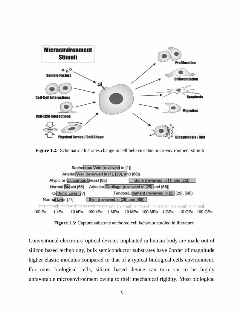
Figure 1.2: Schematic illustrates change in cell behavior due microenvironment stimuli
Figure 1.3: Capture substrate anchored cell behavior studied in literature

4
cells are anchored to substrates with elastic modulus, E, in the range of ~1 to 100
kPa, the moduli of brain-tissue and osteoid, respectively. On the other hand, bulk
semiconductor substrates have ~6 orders of magnitude higher elastic modulus. This
large elastic mismatch between devices and cells natural microenvironments is an
issue for bio-devices integration, as cells are highly sensitive to mechanical cues.
Specifically, cells exert traction forces on their surroundings and adjust their
adhesion mechanism, cytoskeleton, locomotion and overall state according to the
stiffness of the substrate they are anchored to.
Current study is a major step forward in the direction of developing
electronic/photonic devices in biological environment from a mechanical
perspective. In this thesis, I demonstrate a new family of culture platforms to
successfully integrate biological cells and electronic/photonic device material. The
proposed platforms are referred to as effectively compliant layered substrates
(ECLS). ECLS are based on inorganic nanomembranes (NMs) partially suspended
or bonded to compliant substrates. The unique attribute of ECLS is that, the
constitutive material of the NM is an electrically/optically active functional layer
Figure 1.4: a) biological cells anchoring elastic modulus in their native environment b) highlights the
existing mismatch between cell-device mechanical environments.

5
necessary for a device operation, while the NM geometry and the nature of the
supporting substrate are designed to match the mechanical response of biological
tissues
ECLS approaches were developed to control substrate rigidity in three orders of
magnitude. With the underlying premise that device graded compliant platforms
could be used to control cell behavior, the objective of this thesis was to rationalize
the impact of mechanical properties of bulk silicon and establish the merit for
silicon nanomembrane in combination with soft polymers as a platform to achieve
control of substrate rigidity in semiconductor materials. The thesis is divided into
four chapters (excluding introduction). Chapter 2 provides the detailed methods
and characterization techniques employed in this work. It is divided into three
sections, Section 1 introduces fabrication of the effectively compliant layered
substrates (ECLS); containing fabrication of compliant substrate:
Polydimethylsiloxane (PDMS), PDMS modification for biocompatibility, and
Silicon Nano membrane (Si NM) fabrication and integration with the compliant
host. Section 2 provides details on characterization of the effectively compliant
layered substrates (ECLS) using techniques like contact angle measurements for
wettability; and Nano indentation/ Atomic-force microscopy (AFM) for
mechanical characterization of compliant base and ECLS substrates. Section 3
introduces In vitro study: cell culture protocol and cell characterization methods
like flow cytometry for cell viability and cell proliferation and confocal
microscopy for Immunofluorescent staining of cytoskeleton structure. Chapter 3
presents the rationale for ECLS approach derived from previous theoretical study.
Presents results of various formulations of Polydimethylsiloxane (PDMS)
investigated. Results include approach implemented in synthesis of PDMS as a
novel polymer that maximizes the power of mechanical tunablity with simple

6
modifications in the process. Wettability of PDMS formulation and elastic
modulus of substrates is presented. In section 2, I present various ECLS fabricated
by implementing different configuration of Si NM. Chapter 4 starts with
introduction of 3T3 fibroblast in In vitro study. I present results on cell viability;
cell proliferation on Si-based ECLS platform in comparison with bulk silicon. In
final section cell expression such as cell shape, focal adhesion, fiber organizations
associated with substrate rigidity studied on ECLS and bulk silicon are presented.

7
Chapter 2: Experimental Methods
In this chapter, I discuss various experimental techniques employed in my research
study. The first part of chapter 2 deals with, fabrication and characterization
methods of effectively compliant layered substrates. Synthesis of the compliant
substrate of choice is described. Various approached to integrate thin
semiconductor layers are presented. Methods to characterize the structural
properties, as well as the mechanical response and the surface wettability of ECLS
and compliant substrates are elucidated. The second part of chapter 2 illustrates
methods to evaluate cell response on the fabricated substrates, including sample
preparation for in vitro studies, the protocol utilized for cell culture, and cell
characterization techniques (e.g., flow-cytometry and fluorescence microscopy)
2.1. Fabrication of the effectively compliant layered substrates (ECLS)
ECLS fabrication is a two-step process, involving synthesis of the compliant
supporting substrate and fabrication, release and transfer of a thin Si film or
nanomembrane (NM) onto the compliant host.
2.1.1. Compliant substrate: Polydimethylsiloxane (PDMS)
Polydimethylsiloxane (PDMS) belongs to the family of polymeric organo-silicone
compounds. Its chemical formula is CH3[Si(CH3)2O]nSi(CH3)3 where n is the
number of repeating monomer [SiO(CH3)2] units. In my research work I have used
an elastomer-like PDMS, namely Sylgard 184, and a gel-like PDMS or soft
silicone, namely Sylgard 527.

8
PDMS 184 is a two-part elastomer kit with a base and a curing agent. The ratio
between the curing agent and the base defines the degree of cross-linking and the
elastic modulus of the material. Syglard 527 is a two-part gel kit, used as
attenuation to create low stiffness gels of the combined blend. Sylgard 527 gel
consists of Part A and Part B dielectric kit. I have used a blend-
of both 184 and 527 to create hybrid chemically stable PDMS substrates with
tunable mechanical properties. The two blends of PDMS (Syglard 527 and Sylgard
184) are mixed in various mass-to-mass ratios. Reference PDMS substrates are
prepared using Sylgard 527 only and Sylgard 184 only. Manufacturer’s
specifications were used in this process. Manufacturer’s directions for a Sylgard
184 are
(i) Mixing the base and the curing agent in 10:1 ratio;
(ii) twenty minutes degassing (or defoaming) into a vacuum dessicator;
(iii) Curing at 850C for 4 hours.
Figure 2.1: Process steps to obtain hybrid PDMS substrates

9
Manufacturer’s directions for a Sylgard 527 are
(i) Mixing part A and part B in a 1:1 ratio;
(ii) twenty minutes degassing (or defoaming) into a vacuum dessicator;
(iii) Curing at 650C for 12 hours.
Hybrid 527:184 PDMS are fabricated for four different formulations of mass
ratios, as reported in detail in Chapter3. The process steps followed to obtain
hybrid PDMS substrates is summarized in Figure 2.1. Each blend is made by first
preparing pure Sylgard 184 and pure Sylgard 527. Sylgard 527 is prepared by
mixing selected weights of part A and part B, followed by a 10 min defoaming
cycle. Similarly, pure Sylgard 184 is prepared by mixing selected weights of base
and curing agent. The mixture is then placed in a vacuum dessicator for a 20 min
defoaming cycle to remove any air bubbles that arise during mixing of the base and
curing agent. In the final stage, the two mixtures are blended in the selected mass
ratios, followed by an additional defoaming cycle. In each case, once mixed, the
PDMS is poured into 150 mm diameter petri dishes to create 1 mm thick films. All
hybrid PDMS blends are cured at 65oC for 12 hours. Previous studies have
reported that this curing conditions yield a PDMS substrate with stable mechanical
properties over time.

10
2.1.2. PDMS modification
A post-synthesis modification of the PDMS substrates is required to enable
fabrication of ECSL and successful in vitro studies. Specifically, I utilized Soxhlet
solvent extraction to remove uncrosslinked chain in PDMS which may leach out
during in vitro studies, thereby creating a toxic environment for biological cells.
Uncrosslinked chains are also responsible of the tackiness and hydrophobic nature
of the PDMS surface. After Soxhlet solvent extraction, PDMS substrates undergo
Ultraviolet (UV)/ ozone treatments to increase wettability of the surface, and hence
create a more favorable template for NM transfer and cell culture.
Soxhlet Solvent Extraction
PDMS curing is a time- and temperature-dependent process that does not achieve
100% crosslinking. It has been previously demonstrated that even after extensive
curing, as much as 5% (wt/wt %) of the PDMS remains uncrosslinked. Soxhlet
solvent extraction removes unreacted molecules in the polymerized PDMS. In my
experiments cured PDMS substrates are cut into 20 mm PDMS samples using a
punch.
Each PDMS specimen is carefully peeled from the petri dish. Next, PDMS is
washed in de-ionized water (DIW) and sandwiched between a filter paper and a
non-sticky wipe. Several PDMS samples are piled up and mounted into a glass
filter which is then placed in a soxhlet thimble (see Fig. 2.2). This configuration is
used to provide support as well as to facilitate handling of the soft materials. My
selected extraction solvent (acetone/ n-hexane in 1:1 ratio) is placed in a
distillation flask, which is sitting on a hot plate. A reflux condenser is placed atop

11
the extractor. The solvent is heated to its boiling point (i.e., 130oC). Condensation
of the vapor causes the solvent to drip in the thimble containing the PDMS
specimens thereby extracting any uncured oligomers from the material. When the
thimble or soxhlet chamber is almost full, the chamber is emptied by the siphon.
The solvent is returned to the distillation flask. The
thimble ensures that the rapid motion of the
solvent does not transport any solid material to the
distillation flask. Then another extraction cycle
starts. After a 3 h long soxhlet extraction I separate
the various PDMS specimens, remove the wet
filter paper and non-sticky wipe and gently transfer
the swollen PDMS to a new set of non-sticky wipe
and filter paper. After an overnight air dry under
an exhaust hood, samples shrink back to their pre-
Soxhlet dimensions and are then transferred on to a
15mm glass coverslip before further processing.
Ultraviolet/Ozone (UVO) Treatment
The ultraviolet/ozone (UVO) treatment of the PDMS surface is used to convert the
hydrophobic surface of PDMS into hydrophilic. UVO treatment is a
photosensitized oxidation process in which the molecules of the treated material
are excited and/or dissociated by the absorption of short-wavelength UV radiation.
The surface modification of polymers is accomplished by – functional group
implantation. Energetic photons, electrons or ions found in plasma break bonds
within the polymer backbone. Carbon-containing fragments leave the surface in the
form of volatile organic species, while low-molecular weight polymer chains and
Figure 2.2: Setup for
soxhlet extraction

12
Stable radicals remain on the polymer’s surface. The effect of exposing a PDMS
surface to UVO is schematically illustrated in Fig. 2.3. In my experiment the
process is carried out in a commercial UVO chamber (Jelight Company, Inc.,
Model 144AX). In this tool, PDMS specimens are placed into the UVO cleaner
tray at a distance of about 5 mm from the UV source and they are exposed to the
radiation for a controlled period of time. Different amount of treatment times is
tested and are reported in detail in Chapter3. It is to be noted that, samples after
UVO treatment are stored in water before any further use.
Figure 2.3: Surface termination of PDMS before (left) and after UVO
treatment (right)

13
2.1.3. Nano membrane (NM) fabrication and integration with the compliant
host
In this section I discuss the fabrication, release, and transfer of nanomembranes
(NMs). Typically, NMs are fabricated from multi-layer stacked substrates
comprising a functional layer (i.e., the NM) and a sacrificial layer (SL) on a bulk
substrate. In this work, we isolate single-crystalline Si NMs from commercially
available Si-On-Insulator (SOI) substrates. SOI comprises a Si NM, a SiO2
sacrificial and a bulk Si substrate (see Fig. 2.4).
Sample Cleaning
Before any processing, SOI wafers undergo a standard cleaning procedure follows
the concept of Shiraki et al and comprising the following steps:
1. 1 min dip in 5% vol HF solution;
2. 3 min rinse in de-ionized water (DIW);
3. 8 min H2SO4 (66%):H2O2 (33%) dip;
4. 3 min rinse in DIW.
Figure 2.4: SOI multilayered structure.

14
Thermal Oxidation
Thinning of the silicon NM is accomplished by thermal oxidation of the SOI
wafer. During thermal oxidation an oxidizing agent is forced to diffuse into the
wafer at high temperature and react with silicon, thereby creating a high
temperature oxide layer (HTO) on the surface of the SOI wafer (see Fig. 2.5). The
rate of oxide growth is predicted by the Deal-Grove model. Next, the SiO2 is
removed from the surface using a HF solution. In this study, thermal oxidation is
performed in a horizontal tube furnace operated in 1100oC temperature range under
ultra-pure (99.9%) O2 and N2 flow.
Photolithography
Conventional photolithography is used to pattern outline of the membranes onto
SOI wafer. The outline of the membrane is imprinted from a custom designed
chrome etched mask deposited on quartz glass. Here I have used both a positive
(AZ 4330) and an image reversal (AZ5214E) photoresist as per experimental need.
Figure 2.5: Schematic illustration of Si thinning via thermal oxidation and subsequent
oxide removal.

15
The photoresist-covered sample surface is brought into contact with chrome mask
and is exposed for a predefined time under UV lamp using a contact lithography
mask aligning system (Karl Suess MJB-3). The pattern is later developed under
AZ400k base developer solution. A detailed description of the photolithographic
processes used in my work is reported in Table 2.1.
Photolithography Positive Negative
Photoresist AZ4330 AZ5214IR
Sample cleaning 3x Acetone - 1x IPA- N2 blow dry
Surface preparation
Hexamethyldisilane (HMDS) spun at 5000rpm.
Bake at 150◦ C for 1 min
Photoresist spin coating 30 sec at 4500 rpm 30 sec at 5000 rpm
Soft-baking 2 min at 90◦ C 90 sec at 90◦ C
UV light exposure 8-10 sec
Post-exposure baking - 60 sec at 112◦ C
Flood exposure (No mask) - 30 sec
Developer Dip in AZ400K for ~50 sec;
Sample finishing Rinse with water and N2 blow dry
Table 2.1: Photolithographic process used to transfer a pattern on to the photoresist surface

16
The pattern impressed on the photoresist by lithography is transferred to the silicon
template by reactive-ion etching. In this process a reactive chemical gas interacts
with the surface by using a combination of chemical and physical etching
processes. Etch gas atoms are accelerated toward the substrate by a large radio
frequency (RF) voltage, and upon contact chemically react with the surface while
also physically removing material due to their high kinetic energy. In this work,
CF4/O2 is used to etch the silicon down to the sacrificial layer (see Fig. 2.6). RIE
was performed in a Plasmalab μP system at 100 W and chamber pressure of 15
mTorr. The etching rate of Si was estimated to be 30 nm/ min in these conditions.
After RIE photoresist was removed by a dip in acetone cleaning, followed by a 10
min treatment in a nano-stripper solution at 80°C. Additional treatments like
oxygen plasma or conventional 1:3 piranha solution are performed if necessary.
Figure 2.6: Schematic illustration of photolithography and RIE.

17
Membrane release
Release of the membrane is accomplished by selective etching of the SiO2
sacrificial layer in hydrofluoric acid (HF). The release time depends on the
geometry and lateral size of the NM. In this study, we have used perforated
membranes to enhance the access of the etching solution to the sacrificial layer,
which results in a faster membrane release.
To successfully release a membrane employing selective etching process one needs
to understand that the etching process is diffusion-limited, not only by the HF
reaching the SiO2 etch front, but by the out-diffusion of hydrogen gas, a by-product
of the etching reaction. When the undercut channel increases in length, the etch
rate slows down as it is more likely that the hydrogen gas become supersaturated
and form bubbles that may block etchant access to the oxide. In addition to that, if
a membrane is extremely thin (<100nm), the membrane may deflect towards and
reattach to the substrate.
Complete under etching of the membrane is difficult to ascertain visually. The
Teflon containers needed for handling HF are opaque. HF solutions are extremely
hazardous and prevent convenient examination outside of a ventilation hood. If
removed prematurely from solution, membranes will re-attach to the substrate.
Figure 2.7: Schematic illustration of silicon nanomembrane release from SOI wafer.

18
Placing the substrate back into solution rarely reopens the access holes. It is
advised to set a minimum time before checking for membrane release. As a general
rule of thumb, if the membrane is visible, the etching of the sacrificial layer may
not be complete. When membrane is not in direct contact with the substrate, one
can see a reflection of color -gold, cyan, magenta, or blue, depending on membrane
thickness due to the water, oxide, or bubbles between the membrane and the
substrate. If the membrane is completely underetched and hence it is in direct
contact with the substrate, it will be much less visible. After complete removal of
the sacrificial layer the membrane may float off the bulk Si substrate and become
freestanding or it may remain loosely bound to it, a condition called “released in
place”.
Transfer of membranes
Once a membrane is free-standing or released in place, the goal is to place and
strongly adhere the released NM onto the designated new host. The challenge is to
maintain the NM planar geometry and structural integrity during the transfer
process while promoting a strong adhesion at the NM-substrate interface. Transfer
of membranes is one of the trickiest steps by far in fabrication of ECLS, especially
as this is done manually. Membranes are fragile; any applied loads due to poor
handling may easily tear them off. Also, membranes have a tendency to stick to
almost any surface, even Teflon. Once they adhere to a surface, they rarely detach
in one piece. Membrane transfer can be accomplished by following two well
established techniques i.e. Wet and Dry transfer. Essentially, the transfer process
chosen depends on the new host substrate and on the thickness and lateral
dimensions of the membrane.
19
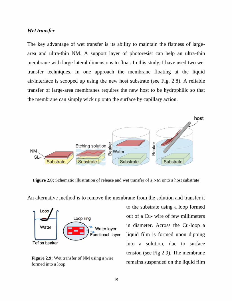
Wet transfer
The key advantage of wet transfer is its ability to maintain the flatness of large-
area and ultra-thin NM. A support layer of photoresist can help an ultra-thin
membrane with large lateral dimensions to float. In this study, I have used two wet
transfer techniques. In one approach the membrane floating at the liquid
air/interface is scooped up using the new host substrate (see Fig. 2.8). A reliable
transfer of large-area membranes requires the new host to be hydrophilic so that
the membrane can simply wick up onto the surface by capillary action.
An alternative method is to remove the membrane from the solution and transfer it
to the substrate using a loop formed
out of a Cu- wire of few millimeters
in diameter. Across the Cu-loop a
liquid film is formed upon dipping
into a solution, due to surface
tension (see Fig 2.9). The membrane
remains suspended on the liquid film
Figure 2.8: Schematic illustration of release and wet transfer of a NM onto a host substrate
Figure 2.9: Wet transfer of NM using a wire
formed into a loop.

20
within the loop until it is placed on the new substrate, and the liquid film is dried
out using a tissue. Although wet processes are reliable to transfer ultra-thin and
large area NMs, they have several disadvantages. Membrane placement on a
substrate by wet transfer is gross at best, and interfacial contamination with any
solutes is more than likely to occur.
Dry transfer
Dry transfer technique helps mitigate some of the above-mentioned problems from
wet transfer. In this study, ECLS are mostly fabricated using dry transfer. A dry
transfer simply is a pick-up process that moves the membrane from one substrate
to another using a stamp. Specifically, once the sacrificial layer is partly removed,
a stamp is used to literally peel-off the NM from the original substrate and transfer
it onto the new host. A stamp needs to establish a strong bond with the membrane
during pick-up, i.e., greater than the adhesion to the original substrate. It is
advantageous to partially underetch a membrane. In this case the unetched portion
of the sacrificial layer oxide will support the membrane and cause it to remain flat.
Depending on the thickness of the membrane, peeling of growth substrate can
generate wrinkles and cracks. The best peeling technique is to pry upward a corner
of the substrate to initiate peeling. This technique prevents sharp bending of the
stamp and membrane. Once peeling is initiated, the growth substrate can be
debonded by holding the substrate with a tweezers and carefully holding the stamp
on a flat surface (see Fig. 2.10).

21
2.2. Characterization of the effectively compliant layered substrates (ECLS)
This section describes the methods employed to characterize the wettability of the
compliant substrates. The technique employed to estimate the elastic moduli of the
bare PDMS and the ECLS is also reported here.
2.2.1. Contact angle measurements
Surface wettability is determined by contact angle measurements. The contact
angle forms when a liquid meets a solid, as the liquid becomes rounded due to its
own surface tension. The contact angle is an angle of straight lines tangent to the
outline of the droplet, at the liquid/solid interface or endpoint of the droplet.
Hydrophobic surfaces have a contact angle with water greater than 90o. On the
other hand, when the contact angle is less than 90o, the surfaces are considered to
be hydrophilic (see Fig. 2.11).
Figure 2.10: Schematic illustration of the release and dry transfer of a NM using a stamp
Figure 2.11: Schematic illustration of a hydrophobic surface, ≥ 90° (left) and a
hydrophilic surface, ≤ 90° (right)

22
Contact angle measurements were performed using a model 100 manual
goniometer (Rame-Hart). Briefly, 5.0 µL drops of deionized water were pipetted
onto the center of the sample surface. The contact angle between the water droplet
and the sample surface was determined using the DROPimage Standard program
(ramé-hart). The contact angles were measured after few sec to obtain the static
contact angle. Each measurement was taken at least 5 times and the results were
averaged out.
2.2.2. Nano indentation/ Atomic-force microscopy (AFM)
Indentation testing is a simple and convenient way to measure the elastic properties
of a material. It involves pushing an indenter tip into a material and measuring the
load versus displacement curve (see Fig. 2.12). In this study, a TI 950
TriboIndenter (Hysitron, Inc.) and an Atomic Force Microscope (Asylum MFP-
3D-BIOTM) are used as nano mechanical testing tool to perform controlled
experiments on compliant base substrate and the effectively compliant layered
substrates.
Figure 2.12: Schematic illustration of indentation technique

23
I use a spherical titanium nitide (TiN) tip with radius 20 nm as an AFM probe for
nanoindentation. Initially, to determine spring constant of the probe a sample with
known stiffness like glass is used. All samples were indented at a constant force.
Five indentations per sample were performed. A schematic representation of a
typical data set obtained with indentation is presented in Fig. 2.13. Parameter P
defines the load and h is the displacement relative to the initial undeformed
surface. The linear range of the unloading curve is analyzed with the Oliver-Pharr
method to calculate the elastic modulus of the sample. The Oliver Pharr method
uses the plot of applied load, P, and penetration depth, h, to find the slope of
material upon unloading, dP/dh. Using slope, I calculated the effective elastic
modulus (Eeff) of the material from Equation 2-1. The deformation height (hf) is
assumed to be zero for elastic body. Displacement (h) in the equation is replaced
with that of max displacement (hmax).
Figure 2.13: Schematic illustration of indentation load–displacement data showing important
measured parameters.

24
𝑆 =𝑑𝑃
𝑑ℎ= 2√𝑅𝐸𝑒𝑓𝑓(h − ℎ𝑓)
1/2 – (2.1)
ℎ = ℎ𝑚𝑎𝑥 & ℎ𝑓 = 0 (Elastic material)
1
𝐸𝑒𝑓𝑓=
1−𝜈2
𝐸+
1−𝜈𝑖2
𝐸𝑖 – (2.2)
The effective elastic modulus (Eeff) includes elastic displacements arising in both
the sample material, with a Young’s modulus (E) and Poisson’s ratio (υ), and the
indenter with elastic constants (Ei) and (υi). Using equation 2-2, The actual elastic
modulus for sample material is determined. Different formulations of PDMS are
characterized for elastic modulus using this technique. PDMS is known to exhibit
essentially elastic behavior in the deformation range applied in this study. Samples
are indent at multiple places to record the homogeneity of the surface. Results for
various PDMS formulation are presented in Chapter 3.
2.3. In vitro study: cell culture protocol and cell characterization methods
In this section I report the methods used in in vitro study to evaluate response of
biological cells on the fabricated substrates. A comparative analysis of cultured
cells on various ECLS platforms and reference substrates is conducted through,
standard studies like cell viability, cell proliferation, cell cytoskeleton and focal
adhesion; characterization techniques like, flow-cytometry, bright-field and
confocal fluorescence microscopy are used for this study.
2.3.1. Cell Culture
All chemicals, culture media and reagents used in this cell culture study are
purchased from Thermo Fisher Scientific, unless otherwise mentioned.
25
Cell Type. Mouse extracted 3T3 fibroblast were used in this study. NIH-3T3
fibroblasts are cultured with Hyclone Classic Liquid Media: Mimimum Essentail
Medium (MEM) Alpha MEM supplemented with 10% (v/v) fetal bovine serum
(Hyclone, Logan, UT), 1% (v/v) penicillin/streptomycin (P/S), and 1% (v/v)
fungizone at 37°C and 5.0% carbon dioxide.
Cells Starting. 3T3 fibroblast cells stored in liquid nitrogen and cell culture media
and any assays stored in refrigerators are warmed up in a water bath before use.
Cell culture workplace has the common requirement of being free from bacteria.
The hood is prepared by cleaning off the surface, containers, flasks, and pipettes
with 70% ethanol to kill off any residing bacteria before used in a hood. Once
3T3s are defrosted and media is warmed up, 15mL of media is added to cover the
surface of 75 cm2 (standard 75T flask) tissue culture polystyrene (TCPS).
Defrosted cells are then added to the flask and are left to grow till 80% confluence
in an incubator at 37°C with 5% CO2. Every two days’ culture media is replaced
by vacuuming off the old media making sure not to scratch cell surface. It is to be
noted that, culture medium is one of the most important components of the culture
environment, because it provides the necessary nutrients, growth factors and
hormones for cell growth, as well as regulating the pH and osmatic pressure of
culture.
Cells Splitting Once cells reach confluence of 80% or greater, cells are split into
new flasks to further continue growing. Split procedure include, pipetting off
media, rinsing cells with 5 mL Dulbecco’s phosphate buffered solution (DPBS),
then use 2 mL of 0.25% (w/v) trypsin which helps cells to pop off from the
surface. 75T flask is then placed in an incubator for ≈ 2-5 mins. After incubation to

26
separate the cells, rock the flask rigorously. Finally, cells floating in trypsin
solution are transferred into two or three new flasks with fresh media.
Cells seeding. Before cell seeding, samples are sterilized for tissue culture use via
a 45 minutes long standard autoclave procedure. Once sterilized, samples are
loaded into a flat bottom non-tissue culture polystyrene 24 well plates (3370,
Corning, Lowell, MA). 24well plate flask has well of size 15 mm diameters each.
All samples studied in this thesis are sized to fit the well. 2ml of media is added to
each well to cover the samples. Cell seeding follows similar procedure to that of
cell splitting up until we have floating cells in trypsin solution. The trypsin solution
is then transferred to a micro centrifuge tubes and centrifuged at 2000 rpm for 5
minutes. Trypsin is pipetted off carefully and the pelleted cells are resuspended in
2 mL of fresh culture media. Cell concentration is determined using a
hemocytometer (1483, Hausser Scientific, Horsham, PA). Samples are seeded with
20,000cells/well by adding corresponding amount of cell solution to each well. As
per experiment, cells are allowed to grow on a particular sample for designated
times in an incubator with standard cell culture environment
2.3.2. Cell characterization: Flow cytometry
Cell growth and viability were quantified using a flow cytometry study. Briefly,
flow cytometry is a laser-based, biophysical technology employed in cell counting,
cell sorting, and biomarker detection. Cells are first stained with antibodies and
visualized by the excitement of fluorescent antibody labels. Stained cells
suspended in a stream of fluid are passed through an electronic detection apparatus,
which allows analysis of the physical and chemical characteristics of particle and
actively separate and isolate particles having specified properties. The Instruments
has multiple lasers and fluorescence detectors allowing for multiple antibodies

27
labeling, and precisely identifying a target population by their respective markers.
For cell viability and proliferation, four samples of each type are cultured with
3T3s fibroblast cells at 20,000cells/well. Cultured cells on samples are assessed at
four time points, i.e., after 12 hrs, 3, 5 and 7 days in vitro (DIV). At each time
point, cells are popped off by 0.25% trypsin, the solution is centrifuged; I carefully
remove the trypsin leaving the cell pellet at the bottom of the tube. Cell pellet is
then resuspended in a 1x annexin binding buffer. Cell proliferation was determined
using AlexaFluor 488 Annexin V/Dead cell apoptosis kit (V13241, Life
Technologies) according to manufacturer’s instructions. All samples are incubated
with 100 ul staining solution [5 uL Annexin V and 1 uL propidium iodide @ 100
lg/mL in 1 annexin binding buffer] for 15 min. Samples are read on Accuri C6
flow cytometer (BD Bio.). For all experiments, media is replaced after every two
days.
Analysis of flow cytometry data involves displaying the data on a sequence of plots
and estimating the percentages of various subpopulations identified from the plot.
The method used for this analysis is a progressive reduction of the raw data into
subsets using gates. The gated cell population is tested for increased annexin
V/Alexafluor 488 and propidium iodine, using quadrant gates. Necrotic controls
are achieved by incubating cells with 70% (v/v) ethanol. Apoptotic controls are
achieved by leaving cultures at room temperature overnight. An unstained cell gate
is established to remove debris.
Optical microscopy
Both inverted and top-down optical microscopes were used to image ECLS
microstructure platforms and to perform cell imaging. In tissue culture, during
time-lapse imaging, the optical microscope was equipped with a micro-incubator
28
(Biosciences Tools,CA, USA), so that the temperature was kept at 37C (Also CO2
(5%) and humidity (95%) were controlled to ensure the appropriate environment
for cells.
2.3.3. Cell characterization: Immunofluorescent staining of cytoskeleton
structure
Cytoskeleton and adhesion mechanisms of the cells on substrate are investigated
through Immunofluorescent staining of cytoskeleton structure and imaging using
confocal fluorescence microscopy. Immunofluorescent staining makes use of
specific antibodies to locate and identify various cell expressions. Primary
antibody is intended to bind to a particular element, while a secondary antibody
conjugated to a fluorochrome is intended to bind to the primary antibody. Upon
absorption of high energy light, the fluorochrome emits light at its own
characteristic wavelength (fluorescence) and thus allows detection of complex cell
expressions
Staining procedure is as follows, I start with fixing 3T3 fibroblast using 10%
formalin for one hour followed by a DPBS wash (2x). Cells are then permeabilized
with 0.01% (v/v) Tween20 in DPBS (PSBT) for 15 min followed by reactive ion
removal using 10% (m/v) sodium azide and 10 M H2O2 in PBST. Sample were
then washed twice with PSBT and placed in Blocking solution (BSA) at room
temp incubated for 30 min. Primary antibodies (MT FITC phalloidin, vinculin)
diluted 1:75 in a 3% (w/v) BSA solution is stained for 60 min at room temp.
Primary antibodies after staining are washed twice with PBST followed by similar
staining procedure for secondary antibodies goat anti-mouse AlexaFluor 488
(A11001, Invitrogen) 1:400 dilution in 3% (w/v) BSA solution for 60 min at room
temperature, followed by a final wash in PBST(2x). In the end, samples were

29
mounted using Fluoromount, F4680–25ML on glass slides and sealed with clear
nail polish.
Confocal microscopy
The confocal microscopy employed specifically captures the emitted fluorescent
light, and allows it to pass through a confocal aperature (pinhole) to reduce the
“out of focus” light. Focused light is then passed through emission filters and
photo multipliers to generate a very high resolution image of the specimen’s
internal expressions.
Images of fluorescently labeled cells are performed on an inverted laser scanning
confocal microscope (Zeiss LSM 510 META microscope) with oil immersed
objectives. Analysis of data involves displaying the data on similar intensities in
respect with gain and set point for F-actin fiber organization and focal adhesion
staining on different substrates.

30
Chapter 3. Results: ECLS fabrication and characterizations
In this chapter, I present effectively compliant layered substrates based on silicon
nanomembranes and PDMS substrates. This chapter is organized in the following
way: in section 3.1 the rationale for ECLS systems in regards with NM for
mechanical matching is elaborated. Section 3.2 shows synthesis, modification and
systematic selection of compliant base from various formulations of PDMS.
Results from characterization of various PDMS for hydrophobicity and mechanical
properties are presented. In section 5.3 the fabrication of various ECLS like, large
area supported, small area supported, and edge thundered are presented with the
help of schematics and optical microscope images. Results from mechanical
characterization of ECLS are reported and discussed in this section.
The key aspects that are involved in development of ECLSs are
1) to define the most suitable NM geometry in order to reduce stiffness;
2) to select an ultra-compliant substrate with mechanical and chemical stability;
3) to fabricate ECLS with a good chemical and mechanical stability;
3.1. Rationale for ECLS approach.
Stiffness (k) is an extensive property of an elastic body and it’s strongly dependent
on 1) the mode of deformation (e.g. stretching, bending, and shear); 2) the elastic
modulus and Poisson ratio of the material; 3) the geometry of the elastic body (see
Fig. 2).
31
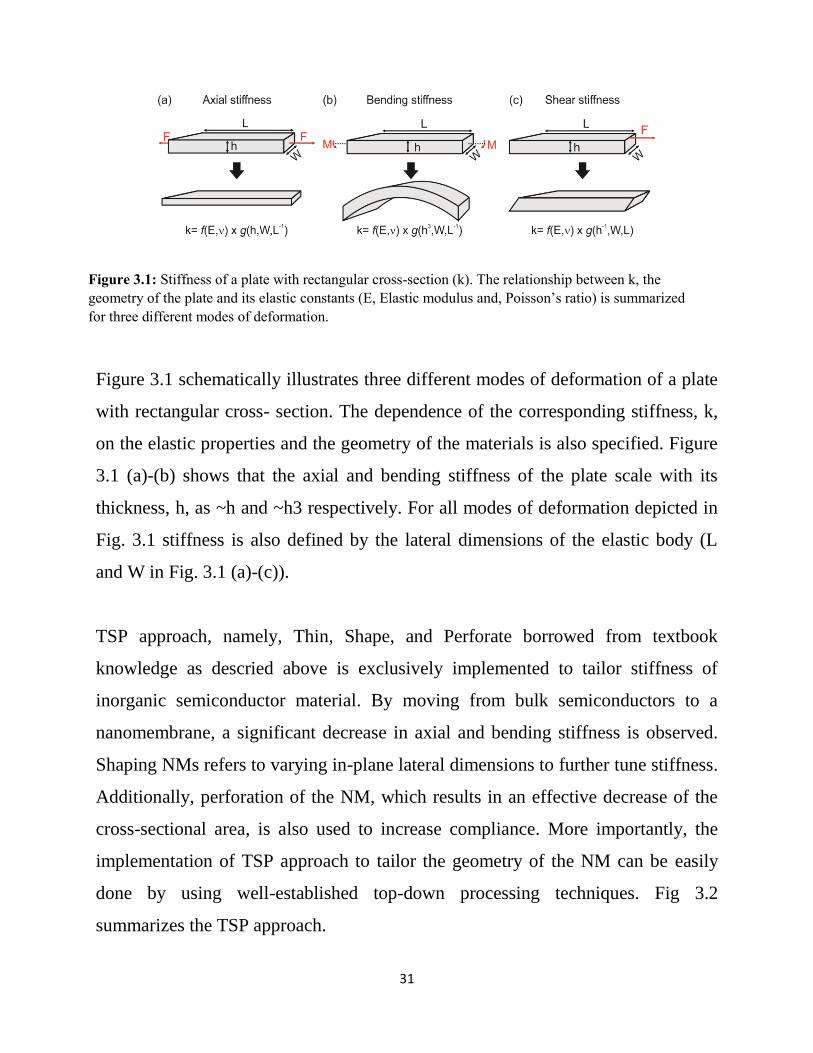
Figure 3.1 schematically illustrates three different modes of deformation of a plate
with rectangular cross- section. The dependence of the corresponding stiffness, k,
on the elastic properties and the geometry of the materials is also specified. Figure
3.1 (a)-(b) shows that the axial and bending stiffness of the plate scale with its
thickness, h, as ~h and ~h3 respectively. For all modes of deformation depicted in
Fig. 3.1 stiffness is also defined by the lateral dimensions of the elastic body (L
and W in Fig. 3.1 (a)-(c)).
TSP approach, namely, Thin, Shape, and Perforate borrowed from textbook
knowledge as descried above is exclusively implemented to tailor stiffness of
inorganic semiconductor material. By moving from bulk semiconductors to a
nanomembrane, a significant decrease in axial and bending stiffness is observed.
Shaping NMs refers to varying in-plane lateral dimensions to further tune stiffness.
Additionally, perforation of the NM, which results in an effective decrease of the
cross-sectional area, is also used to increase compliance. More importantly, the
implementation of TSP approach to tailor the geometry of the NM can be easily
done by using well-established top-down processing techniques. Fig 3.2
summarizes the TSP approach.
Figure 3.1: Stiffness of a plate with rectangular cross-section (k). The relationship between k, the
geometry of the plate and its elastic constants (E, Elastic modulus and, Poisson’s ratio) is summarized
for three different modes of deformation.

32
The rationale for current study for the most part is derived from a recent work, in
which finite-element modeling (FEM) was employed to investigate the effective
mechanical response of ECLS to contact loading. The study demonstrated that the
effective stiffness of a single-crystal (high-modulus) semiconductor sheet on a
low-modulus substrate, with a high mismatch in their elastic moduli (>105), is
defined by the elastic moduli of the constitutive materials, the thickness of the
sheet, and by the extent of the loaded area. In addition, a key relationship was
established between material properties and probe dimensions (i.e., indenter radii)
that define the load deformation response and effective stiffness.
Simulations performed with indenters of various sizes have shown that the
response of SiNMs on compliant substrates approaches that of the bare substrate
when the indenter radius is larger than tens of micrometers. Typical diameters of
biological cells are ~ 100s of micron. Figure 3.3 (Reprinted from F. Cavallo, D. S.
Grierson, K. T. Turner, and M. G. Lagally, ACS Nano, 5, 5400 (2011)) shows that
for such a contact radius matching the lateral dimensions of biological cells the
mechanical response of thin semiconductor films on compliant hosts is determined
by that of the host. As stated earlier, the other major drive in current work is the
availability of techniques to harness intrinsically stiff, electrically and optically
active function material like silicon, in the form of large-area, thin (5 - 100 nm)
Figure 3.2 Proposed approach to tune the stiffness of the ECLS. From left to right, bulk materials
are made into NMs and transferred to a compliant host. (NMs are exceptionally compliant to
bending and axial deformation due to their nanoscale thickness). In addition, NMs are patterned into
lateral dimensions matching the diameter of biological cells and perforated to further reduce their
stiffness.

33
membranes. Fusion of these two ideas suggested that appropriate selection of the
compliant host and NM geometry allows creating inorganic device graded
platforms with stiffness matching the one of a typical cellular environment.
Figure 3.3: Effective stiffness vs. contact radius as determined by FEA for a rigid, cylindrical flat punch
indenting into three bulk materials with elastic modulus of 10 kPa (Substrate A, red dashed line
corresponding roughly to PAAG), 1 MPa (Substrate B, blue dashed line, corresponding roughly to
PDMS), 148 GPa (black dashed line, corresponding to bulk Si); 25 nm and 100nm SiNMs on substrate A
(red solid diamonds and red open diamonds, respectively); and 25 nm and 100nm SiNMs on substrate B
(blue solid squares and blue open squares, respectively). The contact radius, a, is the radius of the
cylindrical indenter, and the SiNM is assumed to be perfectly bonded to the PDMS substrate. Reprinted
from F. Cavallo, D. S. Grierson, K. T. Turner, and M. G. Lagally, ACS Nano, 5, 5400 (2011)
34
3.2. Compliant substrates with tunable mechanical properties:
In this study, the goal is to have a compliant substrate with elastic modulus tunable
between ~0.001 and 1 MPa to match the wide range of elastic properties of
biological tissues. In principle, compliant base substrate for ECLS can be any of
the various commercially available elastomers, such as poly(methylmethacrylate)
(PMMA), polyvinylchloride (PVC), polycarbonate (PC), polystyrene,
polyurethane, and poly(dimethylsiloxane) (PDMS) and etc.
I have chosen poly(dimethylsiloxane) (PDMS) as our base substrate, because
PDMS is inexpensive, easy to fabricate, biologically inert, and optically
transparent, allowing for both optical and fluorescent microscopies. In addition,
PDMS is nontoxic, autoclavable and does not swell or dissolve in culture medium.
For all the reasons listed above, PDMS is widely used as cell culture substrate in in
vitro studies. An additional value is that PDMS elastic modulus can be controlled
in a wide range (~kPa-10s MPa) independently of other materials properties, the
tunable stiffness range from values matching brain-tissue to bones.
As detailed in chapter 2, PDMS is an assembled network of polymer chains which
cross-linked to a certain degree, depending on its composition and fabrication
process. Briefly, commonly used PDMS (Sylgard 184) constitute of a two-part kit,
the base and the curing agent. The kit is to be mixed prior to use and to be cured at
a given temperature/time. In general, the ratio between the curing agent to base
defines the degree of cross-linking and the elastic modulus of the material. The
higher ratios between base and curing agent yield materials with lower elastic
moduli, due to a lower degree of cross-linking in the polymer network. However,
having higher ratios i.e. lesser degree of crosslinking leads in free polymer chains

35
which can leach out over time, thereby creating a toxic environment for biological
cells. In this thesis, instead of just a Sylgard 184 kit, I have used Sylgard 184 in
conjuncture with commercially available elastomer namely Sylgard 527. It is
reported elsewhere, that having a blend of 527 and 184 allows us to fabricate
PDMS in ranges of kPa without any problem of free polymer chains. To attain
lower elastic modulus instead of increasing the ratio between the base and curing
agent, here I increase the ratio between two PDMS kits,
Figure 3.4 shows, Sylgard 184 and Sylgard 527 made as per manufacturer’s
direction in their standard form i.e. Sylgard 184 in 1part curing agent to 10part
base, and Sylgard 527 in 1:1 ratio of PartA and PartB, which allows them to
maintain their stoichiometric stability. Accordingly, we see a standard PDMS
made out of 184 to be a very rigid rubber-like substrate, and on the other hand
standard Sylgard 527 is more like a semi-liquid gel. For a successful ECLS
fabrication the goal is to find a chemically and mechanically stable compliant
substrate. Chemical stability is essential to avoid any toxic behavior which may
influence bioactivity of ECLS in tissue culture. Inadequate mechanical stability of
compliant substrate would cause handling issues during ECLS fabrication process.
Moreover, the objective is to seamlessly vary elastic modulus in wide range
without change in material properties. To do so, various mass-to-mass ratios
between the two kits are varied to tune stiffness of PDMS without any major
change in chemical and mechanical stability. The different formulations of mass
ratios investigated in this thesis are reported in Table 3.1.

36
184: 527 184 (Base: Curing agent):
527 (Part A : Part B)
1:0 (10:1) : (0:0)
1:10 (10:1) : (1:1)
1:20 (10:1) : (1:1)
0:1 (0:0) : (1:1)
1. PDMS 184(10:1) is a standard PDMS with both chemical and mechanical
stability. It is easy to handle and can seamlessly translate into ECLS. Elastic
modulus of PDMS 184(10:1) is reported to be in the range of Mpa. In this
study, as proposed ECLS are specifically aimed at soft cell such as neuronal
cell, brain cells and etc. Elastic modulus in range of Mpa is considered to be
relatively hard. On the other hand, if ECLS are fabricated for a bone-like cell
which prefers a hard substrate, PDMS 184(10:1) is an ideal base substrate for a
Figure 3.4: photographs show a standard 184 (10:1) PDMS and pure 527 (1:1) fabricated as
per manufacture direction, holding by a tweezer
Table 3.1: Formulations of different PDMS investigated in this study
37
Hard ECLS. Nevertheless, for the most part of the study, I use PDMS 184(10:1)
as a bench mark for chemical and mechanical stability for low-elastic gels.
2. PDMS 184(50:1) is a variation of standard PDMS 184 (10:1), it is fabricated by
lowering the crosslinking agent. Here I have reduced PDMS to 50 part of base
to curing agent. It is reported to have elastic modulus in the range of 10’s of
kPa. The reduced elastic modulus in this case is ideal for fabrication of a soft
ECLS platform. Nonetheless, it is argued in the literature that, uncrosslinked
chain can leach out in culture media making it toxic, thus undesirable for cell
study. Moreover, PDMS (50:1) was difficult to handle, extremely adhesive
because of open chains on surface and very gel-like, which makes it
problematic to translate into an ECLS.
3. PDMS hybrid 184:527(1:10) is a blend of 527 (1:1) and 184 (10:1) in 10part to
1part. Here, I am able to maintain stoichiometry of PDMS 184, by fabricated in
its standard ratio, and addition of PDMS 527 kit lower the elastic modulus of
the combined blend. Both pure 527 and pure 184 are independently made and
blended into 10:1 ratio, which yields a PDMS without leasing out chains.
Elastic modulus of hybrid PDMS (1:10) is reported to be in range of 50’s of
kPa. It is exceptionally stable, easy to handle, and can easy be translate into
ECLS.
4. PDMS hybrid 527:184 (1:20) formulation is a blend of 527 (1:1) and 184 (10:1)
in 20parts to 1part. It is fabricated similar to that of hybrid (1:10) instead in
1:20 ratio. The elastic modulus for this formulation is not reported, I expect it to
be in range of 10kPa. Hybrid (1:20) is significantly stable, easy to handle, and
easy to fabricate ECLS.

38
5. PDMS hybrid 527:184 (1:0) is a pure 527 (1:1) ratio. The pure 527 is a
complete gel, claimed to have elastic modulus in the range of 5Kpa. The PDMS
didn’t polymerize, it is a pure semi-liquid gel and fabricating of ECLS out of it
is extremely difficult.
For further processing in ECLS fabrication and In Vito cell culture study, I have
used Hybrid (1:10) and Hybrid (1:20) PDMS as my compliant base substrate based
on their chemical and mechanical stability with elastic modulus in ranges of kPa.
3.2.1. Elastic modulus of different PDMS formulation
The elastic moduli of the different formulations of PDMS discussed above are
measured via nanoindentation technique using an atomic force microscope. A
representative force vs displacement plot generated by indenting standard PDMS
184(10:1) using a TiN coated AFM probe of tip radius 20nm is shown in figure
3.5. The figure displays a red loading curve, a blue unloading curve and a bouncy
retraction of tip at the end which is due to adhesiveness of polymer. I approximate
stiffness(S) of the substrate by measuring the slope of linear region in unloading
curve. Elastic modulus is calculated using standard Oliver-Pharr method defined
for elastic bodies. 5 indentations are done on each sample. Details on indentation
procedure and analysis using Oliver-Pharr method are described in Ch. 2. The
measured elastic moduli for each formulation are presented in Table 3.2.

39
Elastic modulus decreased from 1.87± 0.13 MPa to 78± 0.83 kPa, as expected with
increase in mass ratio of Sylgard 527 relative to Sylgard 184. Evaluation by
nanoindentation displayed discrepancy in elastic modulus for what is reported.
Hybrid (1:10) - 184(10:1) and 527(1:1) is reported to have elastic modulus of
50kPa; however, I measure it to be approx. 140.2 kPa. I assume the variance in
measurement is due to the difference in technique used, as reference measures
elastic modulus using a tensile tester and I expect measurements of AFM used in
this study to be localized then that of a tensile tester. Unreported Hybrid (1:20) -
184(10:1) and 527(1:1) is measured to be approx. 80kPa. Differences between
formulations are found to be significant and the standard deviation of elastic
modulus of samples is found to be within the signal noise and displayed as zero.
Further in this thesis, to fabricate various ECLS platforms and access biological
cells to study mechanical response on fabricated substrate (dedicate cht.4). I have
used hybrid (1:10) -184(10:1)/527(1:1) and hybrid (1:20) -184(10:1)/527(10:1),
because of their respective elastic modulus and mechanical/chemical stability.
PDMS 184:527
Elastic modulus
Standard (10:1) : (0:0)
1.87 ± 0.13 MPa
1:10 (10:1) : (1:1)
138 ± 3.83 kPa
1:20 (10:1) : (1:1)
78 ± 0.83 kPa
Figure 3.5: shows Force vs displacement plot for a 184(10:1) PDMS; Red curve indicates loading
of AFM tip into PDMS; Blue curve indicates unloading of tip from the substrate. Bouncy
retraction of tip from substrate indicated adhesiveness of PDMS.
Table 3.2: Elastic modulus of various Formulations PDMS investigated in this study

40
3.2.2. Modified PDMS
The biocompatibility of a material is determined by its chemical structure, surface
property and surface chemistry, which includes surface functional group, surface
charge, and hydrophilicity/hydrophobicity. PDMS intrinsically is very hydrophobic
in nature, and when diluted to reach lower elastic modulus, it is also observed to be
highly adhesive, which results in difficult handling and low yield during
fabrication of the ECLS.
Accelerated solvent extraction (ASE) n-hexane/acetone (1:1v/v) is used as a
cleaning method to reduce adhesive nature of low-elastic modulus PDMS
formulations in this study. The solvent mixture helps in release of small polymers
from silicone rubber called oligomers, which are potentially causing PDMS to be
adhesive in nature and any loose oligomers leashing out in culture media might
also lead in toxic behavior. An optimized time and temperature (Temp 120-130 for
6-12hrs) was selected to extraction oligomers with highest release rate. The step by
step procedure to undertake cleaning process is presented in Chapter 2.
Figure 3.6: Hybrid 1:20 PDMS (12mm dimeter) undergoing accelerated solvent extraction for
3hrs a) swollen PDMS (left) immediately after treatment, b) samples overnight air dried in fume
hood to allow solvent evaporation(right).
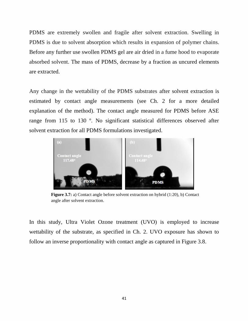
41
PDMS are extremely swollen and fragile after solvent extraction. Swelling in
PDMS is due to solvent absorption which results in expansion of polymer chains.
Before any further use swollen PDMS gel are air dried in a fume hood to evaporate
absorbed solvent. The mass of PDMS, decrease by a fraction as uncured elements
are extracted.
Any change in the wettability of the PDMS substrates after solvent extraction is
estimated by contact angle measurements (see Ch. 2 for a more detailed
explanation of the method). The contact angle measured for PDMS before ASE
range from 115 to 130 º. No significant statistical differences observed after
solvent extraction for all PDMS formulations investigated.
In this study, Ultra Violet Ozone treatment (UVO) is employed to increase
wettability of the substrate, as specified in Ch. 2. UVO exposure has shown to
follow an inverse proportionality with contact angle as captured in Figure 3.8.
Figure 3.7: a) Contact angle before solvent extraction on hybrid (1:20), b) Contact
angle after solvent extraction.

42
PDMS are tested for immediate wettability after fabrication and immediately after
UVO treatment. PDMS are stored in water to avoid any hydrophobic recovery; I
have examined the wettability of stored PDMS after 48 hrs time point, to see if any
hydrophobic recovery happens. Results for different formulation of PDMS are
summarized in Figure 3.9.
Figure 3.8: UV ozone treatment: exposure time vs hydrophilicity.

43
PDMS Type
184:527
(Part A: Part B):
(Base curing : agent
UV-Ozone treatment
(Wettability)
Untreated
(Avg. OC)
0 hours
(Avg. OC)
48 hrs.
in water
(Avg.)
1:0
(10:1) : (0:0)
123 ± 5 54 ± 6 56 ± 5
1:0
(50:1) : (0:0)
121 ± 3 61 ± 2 58 ± 7
1:10
(10:1) : (1:1)
118 ± 4 56 ± 8 54 ± 4
1:20
(10:1) : (1:1)
119 ± 2 54 ± 5 56 ± 6
From the wettability results obtained, it is safe to conclude that UV ozone treated
PDMS do not under go any hydrophobic recovery. Wettability test was conducted
on all formulation of PDMS stored in water. It is seen that PDMS contact angle
measured immediately after UVO treatment remained same after long period of
Figure 3.9: Hydrophobic recovery test a) Contact angle before UV-ozone treatment on hybrid (20:1), b)
Contact angle immediately after UVO treatment, c) Contact angle after 48hrs in water.

44
storage in water. By this point, I have a hydrophilic PDMS, with improved
biocompatibility ready for further processing.
3.3. Various ECLS platforms fabricated
In this section, I describe a variety of planar ECLS platforms fabricated as part of
the study. ECLS simply put are, NMs transferred on to soft substrate (see figure).
Various fabricated planar ECLS include large-area supported NMs on compliant
substrate, small area –pixel NM on compliant substrate, and edge-tethered NMs,
which are partly suspended over the compliant substrate. To realize each ECLS, I
have exclusively used dry transfer technique (detailed in Ch. 2). Schematic and
optical micrographs are used to illustrate ECLS in this section.
Generally, a dry transfer technique employs adhesive stamp to facilitate NM
transfer from growth substrate to a new host substrate. Luckily, PDMS, the
compliant base substrate that I wish to bond my active functional layer to, is one of
the most effective stamps commonly used for dry transfer. PDMS surface energy is
just enough to establish a strong bond with the membrane during pick-up.
Figure 3.10: Schematic illustration of ECLS fabrication.

45
Different types of ECLS are fabricated in this study to achieve varying mechanical
properties by a combination of different configurations of NM and various blends
of PDMS as ECLS. NM configurations implemented are derived from TSP
approach (detailed in section 3.1) TSP stand for, thinning, shaping and perforation.
Here, a large area supported configuration shown in figure is essentially a 1 cm2 x1
cm2 lateral size NM with perforation of 5μm holes spaced 60μm apart, transferred
on a hybrid (1:20) -184(10:1)/527(1:1). Similarly, a small area supported ECLS is
an array of pixel (size: 100μm) transformed on a compliant base. Very minimal to
no change in approach is needed to outline different shapes of membranes on Si-
layer by optical lithography and RIE etch. However, at release stage geometry and
size of NM, i.e. access area provided for the etchant, matters the most. (Detail on
release process is specified in Ch. 3).
Figure 3.11: Illustrates schematic and optical microscopic images of a) Large area supported
ECLS (i.e. 1 cm2 x1 cm2 SiNM 220nm on hybrid PDMS (1:10), b) Small area supported ECLS
(3x3 array of SiNM 220nm pixel of size 100μm on PDMS (1:10)).

46
As mentioned earlier, edge-tethered membranes are partly suspended NM on a
compliant substrate. It is fabricated through a two-step patterning technique.
Firstly, in a conventional way a large area membrane with perforation is fabricated.
After RIE etch and PR removal, the sample undergoes a second step lithography to
define a suspension pattern. Here I have patterned a suspension of 2mm x 2mm
(See figure 3.13) and an array of 100μm pixel (See figure 3.13). Once suspension
is defined using lithography, the pattern is selectively etched on to the membrane
till a desired thickness using RIE (Etch rate and RIE recipe included in Cht2).
Figure shows SINM of 220nm with suspension region of thickness 40nm for both
large area suspension (2mm x 2mm) and pixel (100μm). Schematic illustration of
edge tethered ECLS fabrication process is shown in figure 3.11. Edge tethered
ECLS is realized in final step of peeling SiNM from growth substrate. Result of
suspension in an edge tethered membrane on PDMS is shown in figure 3.11.
Figure 3.11: Schematic illustration of edge tethered ECLS fabrication process.

47
Lastly, figure 3.14 shows, NM with failed transfers (wrinkle and cracks) due to
lack of flatness of membranes during pick-up, improper initial contact, NM with
thickness < 100nm, extremely soft PDMS and also impatient peeling of growth
substrate. All the above mentioned problems and respective solution are explained
in detail in chapter 2.
Figure 3.13: Illustrates schematic and optical microscopic images of a) Large – area edge tethered
ECLS, SiNM 220nm (1cm x 1cm) on standard PDMS (10:1) with 2mm x2mm suspension of 20nm.
b) Edge tethered with 100um suspension of 20nm array on standard PDMS (10:1).

48
3.3.1. Elastic modulus of ECLS
The effective elastic modulus of the ECLS was characterized by a commercial
nanoindentation; specifics are included in chapter 2. The near surface mechanical
properties of ECLS platforms consisting of a 220 nm SiNM with 600μm x800μm
lateral dimensions patterned in checkerboard fashion, with silicon islands of size
80μm x 50μm, transferred onto two different PDMS substrates namely, a hybrid
(1:10) -184:527, a blend of 527 (1:1) and 184 (10:1), with elastic modulus approx.
150kpa, and a standard 184(1:10) 10part base to 1part curing agent, with elastic
modulus of approx. 2Mpa. SiNM/PDMSs are indented using a displacement
controlled quasi static indent to 1500 nm using a conospherical probe with a 5μm
tip radius. 15 indentations are done on each sample. Table 3.3 shows the measured
mechanical properties for each sample at comparable depths.
Figure 3.14: (a) shows an image of 220 nm failed transfer causing wrinkle (b) 20nm SiNM failed
transferred with lots of wrinkle, due to lesser thickness (c) cracks and delamination of 220 nm NM
on a PDMS(<100kPa))

49
SiNM 220nm on
hybrid PDMS (1:10)
SiNM on standard
(10:1) PDMS
Contact Depth (nm) 1138 ± 172 835 ± 53
Storage Modulus (MPa) 0.372 ± 0.019 3.835 ± 0.285
Stiffness (N/m) 2.35 ± 0.17 21.2 ± 1.7
Storage modulus of SINM (220nm) on hybrid (1:10) measured approx. 372 kPa,
and SINM (220nm) on standard (10:1) measured approx. 3.8MPa. SiNM 220nm is
expected to be stiff, the two order of magnitude difference in elastic properties of
ECLS compared to that of its base can be attributed to the thickness of SiNM. The
experimental results fall in agreement with theoretical postulates. Furthermore, this
result clearly shows that by tuning in base material from a hard PDMS to a soft
PDMS, we see a seamless translation of effective elastic modulus in ECLS
structure. One need to acknowledge the fact that, silicon material with ECLS
approach has able to change its intrinsic mechanical property in two orders of
magnitude compared to that of Bulk silicon (140GPa).
Additionally, to determine the relevance of indentation depth with storage
modulus, a probe with 50μm tip radius is indent with a controlled force. 15
indentations are done on each sample. It was observed that with increase in indent
depth effective elastic modulus of ECLS decreased. This result highlights the
impact of base substrate’s elastic properties in determining effective elastic
modulus of hard skin – soft base bilayer system (Shown in figure 3.15).
Table 3.3: Near surface mechanical properties of ECLS samples from low
load indentation with a conospherical probe with a 5μm tip radius

50
Also, as second part of the tests, two ECLS with SiNM of lateral dimension 1cm2
x 1cm2 of two different thickness, specifically SiNM 220nm and SiNM 40nm
transferred onto compliant hybrid (1:10) PDMS were indented using a nano-
indenters. A flat Al probe with 2mm tip radius was indent with controlled force
similar to as stated earlier. Figure 3.16 shows an overlap of loading and unloading
curve of a force vs displacement plot of dissimilar ECLSs and bare PDMS to
compare slope i.e. the change in stiffness, it is observed that SiNM with thickness
in 10’s of nm manages to replicate the slope i.e. stiffness of compliant base
fluently, compared to that of a 220nm SiNM on same base.
Figure 3.15: Storage modulus with respect to contact depth on 220nm SiNM
on standard (10:1) PDMS and 220nm SiNM on Hybrid (1:10) PDMS with a
conospherical probe with a 50μm tip radius

51
In summary, by moving from bulk semiconductors to NMs the stiffness of single-
crystalline silicon is reduced by at least three orders of magnitude, and in addition
if we compose an ECLS with an ultra-compliant base and an extremely thin silicon
film in 10’s of nanometer range, we have an ECLS with elastic properties
matching to that of their base substrate. By way of explanation, effective elastic
properties of ECLS are defined by the elastic moduli of the constitutive materials
and the thickness of the top sheet.
Figure 3.16: Overlap of load vs displacement curve of PDMS; 40nm SiNM
on PDMS and 220nm SiNM on PDMS.

52
Chapter 4: In vitro study of cell response on effectively
compliant layered substrates
In this chapter I access a well characterized in vitro model, such as 3T3 fibroblasts
to evaluate cell response on effectively compliant layered substrates (ECLS).
Specifically, I used flow-cytometry to investigate cell viability and cell
proliferation on Si-based ECLS, as well as on bulk Si and bare PDMS.
Proliferation results presented here focus on evaluating acceptance of ECLS in
tissue culture, and are used to estimate the impact of substrate rigidity on cell
growth; In addition, fluorescence microscopy is employed to capture change in
cellular properties attributed to substrate mechanics, such as shape, spreading, and
adhesion mechanisms.
4.1. 3T3 Fibroblasts
To study cells on fabricated substrates, I have selected 3T3 cell line which is a
standard non-human fibroblast cell line extracted from primary mouse embryonic
fibroblast. 3T3 cells are very stable, easy to clone and maintain in vitro.3T3s can
be bipolar or multipolar and have elongated shapes. I have used these cell lines
primarily because 3T3s are well-characterized for studies related to mechanical
response of cells on substrates. Previous studies have concluded that 3T3
fibroblasts exercises an increase in proliferation; spreading behavior and exhibits
more features of stress fibers and large focal adhesion at increasing substrate
stiffness. Figure 4.1: shown a typical 3T3 change in shape and size due to
substrates elastic modulus.
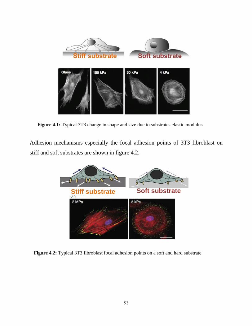
53
Adhesion mechanisms especially the focal adhesion points of 3T3 fibroblast on
stiff and soft substrates are shown in figure 4.2.
Stiff substrate Soft substrate
Figure 4.1: Typical 3T3 change in shape and size due to substrates elastic modulus
Figure 4.2: Typical 3T3 fibroblast focal adhesion points on a soft and hard substrate

54
Several groups noted cell growth and apoptosis are also influenced by substrate
rigidity. Cells on softer gels maintained a 30–35% apoptosis rate compared to less
than 5% on stiffer gels. Thus, increases in cell numbers on substrates of higher
elastic moduli can be attributed to both increased cell proliferation and decreased
apoptosis. Fibroblast responses to changes in substrate rigidity are summarized in
Table 4.1.
Factor Response
Spread area Decrease
Focal adhesion
formation
Decrease
Stress fiber
formation
Decrease
Apoptosis Increase
Proliferation
(cell growth)
Decrease
Migration speed Increase
Traction forces Decrease
Table 4.1: Summary of various response of 3t3 fibroblast to substrate with decreasing elastic
modulus

55
4.2. In vitro study
3T3 fibroblasts are cultured In vitro on four types of substrates, namely tissue-
culture polystyrene (TCPS), bulk silicon, bare PDMS, and ECLS. A detailed
description of the samples structures used in the vitro study is reported in Table
4.2.
Substrate
Tissue
culture
Poly-
sterene
(TCPS)
PDMS
184:527
1:10
PDMS
184:527
1:20
Bulk Si
PDMS
184:527
1:10
PDMS
184:527
1:20
Skin None None None 40 nm
SiNM
220 nm
SiNM
<20 nm
SiNM
220 nm
SiNM
The samples structures specifically TCPS and bulk
silicon serve the purpose as reference rigid culture
substrate for cell response, whereas bare PDMS serves
as a soft substrate with elastic modulus in the range of
kPa.
In a preliminary study, ECLS consisting of hybrid
PDMS (1:10) and SiNM of thickness 220nm and 40nm
were studied using optical microscopy for 12hour time
point to access cell attachment and over 7days to access
cell proliferation shown in figure 4.3.
Table 4.2: Summary of all the substrate used for In vitro study

56
bottom-up bright field images of 3T3 fibroblasts cultured on TCPS, hard PDMS
and ECLS, namely 220 nm Si/hybrid PDMS (1:10) and 40 nm Si/hybrid PDMS
(1:10). Images were taken 12 hours after seeding, seeded at a density of ~18,000
cells/well. No data are available for bulk Si due to the lack of transparency of this
substrate in the visible range. This highlights one more advantage of using ECLS,
namely the possibility of interfacing cells with a device grade semiconductor, and
still being able to assess cell status via bottom-up bright filed microscopy. All this
is enabled by the extreme thinness of Si NM, which allows electromagnetic
radiation to be transmitted through the film. Imaging and analysis is performed
manual in 6 different regions of the investigated substrates.
Results obtained by optical microscopy have shown reasonable cell attachment in
all four samples type presented. However, due to low sample size and inability of
imaging bulk Si, I have used a commercially available assay to quantify cell
viability and proliferation, discussed in detail in following section. Figure 4.3
shows bottom-up bright field imaging of 3T3 fibroblasts cultured on,220 nm
Si/Hybrid PDMS (1:10) was performed at 3, 5 days in vitro.
Figure 4.3: Bright field optical images of 3T3 fibroblast cultured in vitro on a fabricated specimen
including a 220 nm Si NM/PDMS. The Si NM is perforated with an array of 2D holes. The images
were acquired using an inverted microscope over (1-5) days in vitro (DIV). The images clearly show a
healthy proliferation of the cells on investigated surfaces over the course of study, thereby confirming
the viability of 3T3 fibroblasts on the fabricated specimens.

57
Results: Cell viability and cell proliferation using flow cytometry
All samples studied using flow cytometry are sterilized by autoclave and
functionalized using UV ozone plasma facilitating similar surface functional
groups; eliminating effects of surface chemistry (see Ch. 2 for additional details on
UV ozone plasma). 3T3s are seeded at a density of ~25,000 cells/well on various
samples namely, bulk Si, bare PDMS/hybrid (1:20) and SiNM 220nm on hybrid
(1:20). Samples are placed in a 24-well plate flask with 1.5 cm diameter well.
Fabricated ECLS is a 1 cm2 x1 cm2 lateral size NM with perforation of 5μm holes
spaced 60μm apart, transferred on a hybrid (1:20) PDMS. ECLS, bulk silicon and
bare PDMS are tailored to fit the culture well. The Alexa Fluor® 488 annexin
V/Dead Cell Apoptosis Kit with Alexa® Fluor 488 annexin V and PI for flow
cytometry is employed to classify cultured cell population into live and dead cells;
specifically, apoptotic cells are labeled with green fluorescence; dead cells with red
fluorescence, and live cells with little or no fluorescence. Cell population is then
distinguished using a 488 nm line of an argon-ion laser for excitation. Control
experiment determines gates used to exclude debris. Detailed experimental
procedures are described in chapter 2. Figure 4.3, shows proliferation of 3T3
fibroblast on ECLS platform (220nm/hybrid (1:20)). The graph in figure 4.4 shows
the viability values (i.e. the number of living cells in percentage on a particular
sample for a definite time point) of 3T3 fibroblast on three different substrates. For
a material to be considered safe and biologically acceptable there should be little to
no apoptosis which implies the living cell population on a substrate should be over
70%. From the graph, we can see that the viability values for days 0-7 range from
75% – 92%, well beyond the safe range. Bulk silicon and ECLS (220nm/hybrid
(1:20)) have promoted more initial cell attachment and viability then that of
PDMS. Owing to UVO treatment of all samples, I assume same function group at
the surface of PDMS, bulk silicon and SiNM/PDMS, in which case the lesser

58
initial attachment of 3T3 fibroblast on PDMS can be solely attributed to stiffness
of substrate. The most important take away from this result is, ECLS have
promoted heathy cell growth over the course of experiment; the specific stiffness
impact on 3T3 fibroblast on Si substrate with varying mechanical properties is
studied in next section using ICC staining of cells.
Figure 4.5 is a graph referred to as growth curve or cell proliferation curve, with
time in culture media on X-axis and cell count on Y-axis. Essentially, living cell
population for each time point obtained from flow cytometry is plotted with
respect to culture time. In general, a healthy cell growth on a substrate is expected
to have a generic trend of exponential growth over time. Here, 3T3 fibroblast are
initially seeded at 25,000 cells/well cultured on three different substrates namely;
ECLS (SiNM 220nm on PDMS), bulk silicon and hybrid (1:20) PDMS. I consider
Figure 4.4: Living cell population of 3T3 fibroblast at four specific time periods; if a substrate reads
70% or more living cells, substrate is considered to be biocompatible

59
performance of bulk silicon to be similar to that of standard tissue culture substrate
i.e. polystyrene TCPS. 3T3 fibroblasts had shown statistically significant impact on
the cell growth on substrate with elastic modulus less than 10 kPa gels after 24 and
48 h, respectively. Here, the stiffness of the ECLS is in range of more than
100kpa. Therefore, stiffness influence on rate of the proliferation suggests cells
experience relatively similar stiffness on ECLS (220nm/hybrid (1:20) PDMS)
compared to that of rigid silicon wafer which is understandable as SiNM 220nm is
stiff (Refer section on Nanoindentation). Graph shows all the substrate attains
confluent culture at day 7. All three substrates used to analyze the number of cells
on the substrates resulted in observation of the standard trends throughout the
study. The standard deviation for all substrate increases with culture time. The bulk
silicon substrate by the end had greatest standard deviation. The large standard
deviation is associated with the clustering of cells as cell density increased.
4.2.2 Actin Cytoskeleton and Focal Adhesion:
Figure.4.5. Growth curve associated with three different samples with drastic change in elastic modulus;
SiNM/PDMS (approx. 160kPa); bare PDMS (approx. 80kPa) and bare silicon (approx. 164 GPa).
Number of viable cells stained with CyQuant Direct Cell Proliferation assay measured with flow
cytometer.

60
Results: Actin Cytoskeleton and Focal Adhesion
3T3 fibroblast cell structure is reported to show evident effects of substrate
rigidity, particularly, F-actin fibers and focal adhesions points. To study change in
cell structure on fabricated substrates, I have used immunofluorescent staining of
cytoskeleton containing specific fluorescent-label to map local orientation of actin
filaments within cell and a monoclonal antibody to stain focal contacts in cells.
Confocal fluorescence microscopy was used to detect any alteration in shape and
size of 3T3 fibroblast with respect to substrates with dissimilar mechanical
properties. Specifically, the isolated cell response is evaluated from stress fiber
organization and focal adhesions.
Results presented in Figure 4.6 show 3T3 fibroblast on bulk Si, 220 nm Si/Soft
PDMS (i.e. hybrid (1:20) PDMS) and <20 nm Si/Soft PDMS. The surface
chemistry of the selected culture platforms is identical. On the other hand, the
effective elastic moduli of the three substrates are dramatically different; as a
result, change in cells response is solely attributed to mechanical cues of culture
substrate. In each figure, the representative cell shape, size and orientation of 3T3
on different substrates is captured. Figure 4.6.a shows 3T3 fibroblasts on bulk Si,
3T3s on silicon were observed to have a large cell size and wide spread which is
expected of 3T3s cultured on stiff substrates (see section on 3T3s fibroblast typical
behavior). Fig 4.6.b shows cells on ECLS comprising 220 nm Si on soft PDMS
(i.e. hybrid (1:20). We can see reduction in cell spread area on this substrate. Fig
4.6.c has ECLS with silicon < 20nm on hybrid (1:20) PDMS, approx. 80kPa elastic
modulus. Here we see a significant change in cell shape and spread area of 3T3s,
which is expected of 3T3s cultured on soft substrate.

61
I have also investigated stress fiber organization and focal adhesion of isolated
cells on bulk Si, 220 nm Si/Soft PDMS, and <20 Si/soft PDMS. Confocal
microscopy images are shown in Fig. 4.7 displays cells stained for cytoskeleton.
3T3 fibroblasts culture on bulk Si and 220nm Si/PDMS have distinct stress fiber
organization and elongated stable focal adhesion points as shown in fig 4.7.a. and
4.7.b. Figure 4.7.c shows 3T3 fibroblast on <Si 20 nm/PDMS. Fiber organization
on this substrate was barely in detectable levels and also diffused adhesion points
were observed. We see significant change in structure definition between a bare Si
and a soft ECLS substrate. The 3T3 behavior observed here on ECLS (<20nm)
with elastic modulus of 80 kPa is in line with what is expected from 3T3 fibroblast
response on soft substrates.
Figure.4.6. illustrate 3T3 fibroblast change in size, shape and orientation with
respective mechanical properties of substrate. a) Bulk silicon (in Gpa range). b) Hard
ECLS composed of SiNM 220nm on PDMS hybrid (1:20), elastic modulus approx.
160kPa c) soft ECLS with Si NM 20nm on hybrid PDMS (1:10) elastic modulus approx.
80kpa.

62
A significant difference in fiber organization between bulk Si and soft ECLS can
be seen, unorganized and unstable fiber organization in 3T3 fibroblast are
characteristic of its behavior on soft substrate. The 3T3 on the Hard ECLS had
Figure 4.7: Single cell focal attachment points and F- actin fiber organization on substrates
with different mechanical properties. a) 3T3 fibroblast on bare silicon wafer (Elastic
modulus approx. 140Gpa). b) hard ECLS comprised of SiNM 220nm on PDMS hybrid
(1:20), elastic modulus approx. 160kPa. c) soft ECLS with Si NM 20nm on hybrid PDMS
(1:20) elastic modulus approx. 80kpa.

63
little stress fiber organization compared to that of soft ECLS. However, on softest
ECLS never to no stress fiber organization was observed which is similar to that of
bare PDMS.

64
Chapter 5: Summary and Future directions
Summary
In this thesis, an Effectively Compliant Layered Substrate (ECLS) approach was
proposed to address the issue of mechanical mismatch between cell-device
microenvironment. I have successfully implemented the technique to engineer
various Si-based ECLS platform with dissimilar mechanical properties using nano-
fabrication technology. Ideological reasoning for using such approaches and length
scales essentially was to acknowledge the drastic change in mechanical properties
of an intrinsically rigid substrate in the range of three orders of magnitude
accomplished just by moving from bulk material to nanomembrane. This thesis
was divided into three main sections, each of which focused on a particular aspect
of the ECLS.
The first section of the thesis aimed at synthesis of a biocompatible, chemically
and mechanically stable compliant substrate as support base for ECLS platform. In
order to achieve this, various PDMS formulations were developed to fabricate
compliant base with elastic modulus in the ranges of kPa. Wetting properties of the
polymer stamp were improved by UVO treatment to promote healthy bioactivity.
In final stage, the compliant substrates created by this method were seamlessly
translated into various ECLS platforms.
In the second portion of this thesis various configurations of SiNM were realized
using a technique called TSP approach namely, thinning, shaping, and perforating.
The idea was to see the extent to which mechanical properties of silicon in
nanoscale can be tailored. In order to do so, SiNM of various thicknesses were
transferred on to a compliant base with similar mechanical properties. Bilayers
were characterized using nano-indentation to meausure effective elastic modulus of

65
substrates. It was demonstrated that SiNM in tens of nanometer thickness
replicates mechanical properties similar to that of its compliant base
In the third portion of this thesis, In-vitro cell study was conducted using 3T3
fibroblast cell line to test cell viability and cell growth on ECLS platforms.
Additionally, cell expressions like fiber organization and focal adhesion were used
as indication of change in mechanical properties of fabricated platforms. The
results show a significant difference in cell behavior at different levels. 3T3s were
observed to change shape, size, and expression corresponding to change in
mechanical properties.
In conclusion, by implementing proposed techniques, I was able to fabricate a
combination of robust and reliable non-biodegradable silicon electronics material
based compliant platforms which offers both the flexibility of the device and
sufficient bulk degradation that the immune response to the remaining material is
minimal. Proposed ECLS have offered exceptional biocompatibility and
mechanical sensitivity. In addition, ECLS approach makes non transparent bulk
silicon into an optical transparent platform allowing bright field imaging in tissue
culture environment. The next generation of ECLS promises more efficient and
comprehensive bio-device integration. Proposed compliant culture platforms can
find immediate application in clinical research for therapeutic strategies in wound
healing and tissue engineering.

66
Future directions
As it can be seen from this chapter, much progress has been made in
controlling mechanical properties of ECLS by tailoring compliant base and
functional layer. One direction for future work can be study of different type
of cells; especially study of neuronal cell on fabricated substrates with
device functionality may revolutionize in vitro study of neuronal cells.
The next obvious step is the characterization of electronic and photonic
response of ECLS platforms in tissue culture. Figure 5.1 shows a schematic
of proposed process flow to facilitate device functionality.
Another direction for future work is to investigate stable compliant base in
the range of approx. 20kPa or less, such that it facilitates easy ECLS
fabrication. Despite significant progress presented in this thesis, to
distinguish drastic cell expressions, common studies in mechanobiology
employ hydrogels for a wide variety of biological tissue. Compliant base
elastic modulus used in this study can be further decreased by varying the
Figure 5.1: Hall bar fabrication, release and transfer on the compliant substrate.
Hall bars are fabricated on the unreleased NM by conventional top-down
processing techniques (a)-(b). A support layer is spun onto the fabricate device (c)
to provide mechanical stability during release and transfer to the compliant host
(d). The support layer is finally cleaned by solvents (e).

67
ratio of 184 kits in the hybrid blend of 184:527 from standard 10parts base
to 1part curing agent to (20:1); (30:1) and (50:1). However, this might
increase the possibility of more loose oligomers with increased dilution,
extra time in solvent extraction should help.
Lastly, in the view of creating more relevant biological condition on-chip,
device graded substrates should be investigated as a platform for 3D cell
culture by facilitating 3D microstructures on ECLS platforms. The work
would include realization of 3D scaffolds on ECLS and their integration in
tissue culture with device functionality. Figure 5.2 shows fabricated 3D
microstructures on ECLS. Out of plane microstructures on ECLS were
realized by following the process of guided-self-assembly procedure.
Primarily, NM is designed with organized stress concentrators. The adhesion
energies between the bi-layers are manipulated. Finally, by controlled
compressive stress induction and eventual stress relaxation I realize 3D
microstructures on ECLS.
Figure 5.2: a) Groove like 3D microstructure on ECLS. b) Buckle like
3D microstructure on ECLS
68
Reference
1) Fissell, W.H.; Fleischman, A.J.; Humes, H.D.; Roy, S. Development of continuous
implantable renal replacement: past and future. Transl. Res. 2007, 150, 327–336.
2) Fissell, W.H.; Manley, S.; Westover, A.; Humes, H.D.; Fleischman, A.J.; Roy, S.
Differentiated growth of human renal tubule cells on thin-film and nanostructured
materials. ASAIO J. 2006, 52, 221–227.
3) Salonen, J.; Kaukonen, A.M.; Hirvonen, J.; Lehto, V.P. Mesoporous silicon in drug
delivery applications. J. Pharm. Sci. 2008, 97, 632–653.
4) Anglin, E.J.; Cheng, L.; Freeman, W.R.; Sailor, M.J. Porous silicon in drug delivery
devices and materials. Adv. Drug. Deliv. Rev. 2008, 60, 1266–1277.
5) Canham, L.T. Bioactive silicon structure fabrication through nanoetching techniques.
Adv. Mater. 1995, 7, 1033–1037.
6) Whitesides, G.M.; Ostuni, E.; Takayama, S.; Jiang, X.; Ingber, D.E. Soft lithography
in biology and biochemistry. Annu. Rev. Biomed. Eng. 2001, 3, 335–373.
7) Xia, Y.N.; Whitesides, G.M. Soft lithography. Annu. Rev. Mater. Sci. 1998, 28, 153–
184.
8) Makamba, H.; Kim, J.H.; Lim, K.; Park, N.; Hahn, J.H. Surface modification of
poly(dimethylsiloxane) microchannels. Electrophoresis 2003, 24, 3607–3619.
9) Mirzadeh, H.; Shokrolahi, F.; Daliri, M. Effect of silicon rubber crosslink density on
fibroblast cell behavior in vitro. J. Biomed. Mater. Res. A 2003, 67, 727–732.
10) Ali Khademhosseini. Nanoscale and Microscale Approaches for Engineering the in
vitro Cellular Microenvironment
11) Leclerc, E.; Sakai, Y.; Fujii, T. Perfusion culture of fetal human hepatocytes in
microfluidic environments. Biochem. Eng. J. 2004, 20, 143–148.
12) Ostrovidov, S.; Jiang, J.L.; Sakai, Y.; Fujii, T. Membrane-based PDMS
microbioreactor for perfused 3D primary rat hepatocyte cultures. Biomed. Microdev.
2004, 6, 279–287.
13) Berit Brockmeyer1 & Uta R. Kraus1 & Norbert Theobald1. Accelerated solvent
extraction (ASE)for purification and extraction of silicone passive samples.
14) Irena Barbulovic-Nad New Microfludic Platform for Cell studies.
15) Chetan Bhuwania. Substrate Stiffness Adustable PDMS Device/Array for
Understanding Its Effects onCell Growth, Differencationand Migration
16) Ming Ni 1, Wen Hao Tong 1,2, Deepak Choudhury 1,2, Nur Aida Abdul Rahim 3,
Ciprian Iliescu 1,* and Hanry Yu 1,2,3,4,5- Cell Culture on MEMS Platforms: A
Review
17) Chun-Min Lo,* Hong-Bei Wang,* Micah Dembo,† and Yu-li Wang* Cell Movement Is
Guided by the Rigidity of the Substrate
18) Anna M Clausen. Using Silicon Nanomembranes to Evaluate Stress in Deposited Thin
Films
19) Arnold Melvin Kiefer. Silicon/Germanium Junctions Formed by Membrane bonding.
20) Tony Yeung,1 Penelope C. Georges,1 Lisa A. Flanagan,2 Beatrice Marg,2 Miguelina
Ortiz,1 Makoto Funaki,1 Nastaran Zahir,1 Wenyu Ming,1 Valerie Weaver,1 and Paul
A. Janmey1,2* Effects of Substrate Stiffness on Cell Morphology, Cytoskeletal
Structure, and Adhesion

69
21) Nan Sun¶,*, Yong Liu#, Ling Qin§, Guangyu Xu§, and Donhee Ham§,* Solid-State
and Biological Systems Interface
22) Francesca Cavallo and Max G Lagally* Semiconductor nanomembranes: a platform
for new properties via strain engineering
23) Francesca Cavallo* and Max G. Lagally Semiconductors turn soft: inorganic
nanomembranes
24) Je ́roˆme Solon,*y Ilya Levental,*z Kheya Sengupta,*{ Penelope C. Georges,*z and
Paul A. Janmey*§ Fibroblast Adaptation and Stiffness Matching to Soft Elastic
Substrates
25) Masha Prager-Khoutorsky1,4,5, Alexandra Lichtenstein1,4, Ramaswamy
Krishnan2,5, Kavitha Rajendran2,5, Avi Mayo1, Zvi Kam1, Benjamin Geiger1,6 and
Alexander D. Bershadsky1,3,6 Fibroblast polarization is a matrix-rigidity-dependent
process controlled by focal adhesion mechanosensing
26) W.C. Oliver G.M. Pharra Measurement of hardness and elastic modulus by
instrumented indentation: Advances in understanding and refinements to methodology
27) Michelle M. Kelly Elastic Strain Sharing in Silicon/Silicon Germanium
Nanomembrane.
28) Sara Molladavoodi Investigating Mechanical Interactions of Cells with Their
Environment
29) Minghuang Huang,*a Francesca Cavallo,a Feng Liub and Max G. Lagallya
Nanomechanical architecture of semiconductor nanomembranes
30) Deborah Marie Paskiewicz Elastic Strain Engineering in Silicon and Silicon-
Germanium Nanomembranes
31) Zhixin Wang Polydimethylsiloxane Mechanical Properties Measured by Macroscopic
Compression and Nanoindentation Techniques
32) Kirill Efimenko,∗ William E. Wallace,† and Jan Genzer∗, 1Surface Modification of
Sylgard-184 Poly(dimethyl siloxane) Networks by Ultraviolet and Ultraviolet/Ozone
Treatment
33) J. A. Rogers1, M. G. Lagally2 & R. G. Nuzzo3 Synthesis, assembly and applications
of semiconductor nanomembranes
34) Matthew N. Rush1,2, Kent E. Coombs1,3, and Elizabeth L. Hedberg-Dirk1,2,4*.
Surface Chemistry Regulates Valvular Interstitial Cell Differentiation In Vitro
35) Fut K. Yang, Wei Zhang, Yougun Han, Serge Yoffe, Yungchi Cho, and Boxin Zhao*
“Contact” of Nanoscale Stiff Films
36) Li-Heng Cai, Thomas E. Kodger, Rodrigo E. Guerra, Adrian F. Pegoraro, Michael
Rubinstein,* and David A. Weitz* Soft Poly(dimethylsiloxane) Elastomers from
Architecture- Driven Entanglement Free Design
37) Jessica M. Dechene Surface Modi cations of Poly(dimethylsiloxane) for Biological
Application of Micro uidic Devices
38) Qian Wang Elastomer-based Cellular Micromechanical Stimulators for
Mechanobiological Study
39) Dennis E. Discher,1* Paul Janmey,1 Yu-li Wang2 Tissue Cells Feel and Respond to
the Stiffness of Their Substrate
40) Christine E. Schmidt1 and Jennie Baier Leach2 NEURAL TISSUE ENGINEERING:
Strategies for Repair and Regeneration
70
41) A. Evren Özçam 1, Kirill Efimenko, Jan Genzer*Effect of ultraviolet/ozone treatment
on the surface and bulk properties of poly(dimethyl siloxane) and poly(vinylmethyl
siloxane) networks
42) Francesca Cavallo,* Kevin T Turner1, and Max G Lagally Facile Fabrication of
Ordered Crystalline-Semiconductor Microstructures on Compliant Substrates
43) [W. P. Dumke, J. M. Woodall, and V. L. Rideout “GaAs-GaAlAs Heterojunction
Transistor for High Frequency Operation” Solid-State Electronics 15 (1972)
1339─1343
44) B. A. Irving “The Preparation of Thin Films of Germanium and Silicon” British
Journal of Applied Physics 12 (1961) 92─93
45) M. Bruel “Silicon on Insulator Material Technology” Electronics Letters 31 (1995)
1201─1202
46) O. Moutanabbir and U. Gösele “Heterogeneous Integration of Compound
Semiconductors” Annual Review of Materials Research 40 (2010) 469—500.
47) D. J. Monk, D. S. Soane, and R. T. Howe “Hydrofluoric Acid Etching of Silicon
Dioxide Sacrificial Layers: II. Modeling” Journal of the Electrochemical Society 141
(1994) 270 – 274
48) J. Bühler, F.-P. Steiner, and H. Baltes “Silicon Dioxide Sacrificial Layer Etching in
Surface Micromachining” Journal of Micromechanical Machining 7 (1997) R1 – R13
49) K. R. Williams, K. Gupta, and M. Wasilik “Etch Rates for Micromachining
Processing—Part II” Journal of Microelectromechanical Systems 12 (2003) 761 – 778
50) in Ge and Associated Defect Control” Journal of Electrochemical Society 153 (2006)
G229 – G233 Adams CL, Nelson WJ. 1998. Cytomechanics of cadherin-mediated cell-
cell adhesion. Curr Opin Cell Biol 10:572–577.
51) Balaban NQ, Schwarz US, Riveline D, Goichberg P, Tzur G, Sabanay I, Mahalu D,
Safran S, Bershadsky A, Addadi L, Geiger B. 2001. Force and focal adhesion
assembly: a close relationship studied using elastic micropatterned substrates. Nat Cell
Biol 3:466 – 472.
52) Bao G, Suresh S. 2003. Cell and molecular mechanics of biological materials. Nat
Mater 2:715–725.
53) Bard JB, Hay ED. 1975. The behavior of fibroblasts from the devel- oping avian
cornea. Morphology and movement in situ and in vitro. J Cell Biol 67:400–418.
54) Cunningham CC, Vegners R, Bucki R, Funaki M, Korde N, Hartwig JH, Stossel TP,
Janmey PA. 2001. Cell permeant polyphosphoi- nositide-binding peptides that block
cell motility and actin assembly. J Biol Chem 276:43390–43399.
55) Danjo Y, Gipson IK. 1998. Actin “purse string” filaments are anchored by E-cadherin-
mediated adherens junctions at the leading edge of the epithelial wound, providing
coordinated cell movement. J Cell Sci 111:3323–3332.
56) Rogers JA, Lagally MG, Nuzzo RG: Semiconductor nanomembranes: synthesis,
assembly, and applications. Nature 2011, 477:45.
57) Ahn JH, Kim HS, Lee KJ, Jeon S, Kang SJ, Sun Y, Nuzzo RG, Rogers JA:
58) Heterogeneous three-dimensional electronics by use of printed
59) Semiconductor nanomaterials. Science 2006, 314:1754.3. Khang DY, Jiang HQ,
Huang Y, Rogers JA: A stretchable form of single- crystal silicon for high-
performance electronics on rubber substrates.
71
60) Science 2006, 311:208.4. Roberts MM, Klein LJ, Savage DE, Slinker KA, Friesen M,
Celler GK, Eriksson
61) MA, Lagally MG: Elastically relaxed free-standing strained-silicon
62) nanomembranes. Nat Mater 2006, 5:388.
63) D. Tabor, Review of Physics in Technology, 1970, 1, 145–179.
64) Membrane Handbook, ed. W. S. W. Ho and K. K. Sikar, Chapman and Hall, New
York, 1992.
65) J. Li, M. Gershow, D. Stein, E. Brandin and J. A. Golovchenko, Nat. Mater., 2003, 2,
611–615.
66) M. G. N. Fertig, M. Klau, R. H. Blick and J. C. Behrends, Appl. Phys. Lett., 2002, 81,
4865–4867.
67) M. M. Roberts, L. J. Klein, D. E. Savage, K. A. Slinker, M. Friesen, G. K. Celler, M.
A. Eriksson and M. G. Lagally, Nat. Mater., 2006, 5, 388–393.
68) S. A. Scott and M. G. Lagally, J. Phys. D: Appl. Phys., 2007, 40, R75– R92.
69) N. Bowden, S. Brittain, A. G. Evans, J. W. Hutchinson and G. M. Whitesides,
Nature, 1998, 393, 146–149.
70) J. Huang, M. Juszkiewicz, W. H. de Jeu, E. Cerda, T. Emrick, N. Menon and T. P.
Russell, Science, 2007, 317, 650–653.
71) F. Liu, P. Rugheimer, E. Mateeva, D. E. Savage and M. G. Lagally, Nature, 2002,
416, 498.
72) Y. Mei, D. J. Thurmer, F. Cavallo, S. Kiravittaya and O. G. Schmidt, Adv. Mater.,
2007, 19, 2124–2128.
73) M. Huang, C. Boone, M. M. Roberts, D. E. Savage, M. G. Lagally, N. Shaji, H. Qin,
R. Blick, J. A. Nairn and F. Liu, Adv. Mater., 2005, 17, 2860–2864.
74) Levental, I., P. C. Georges, and P. A. Janmey. 2007. Soft biological materials and their
impact on cell function. Soft Matter. 1:299–306.
75) Engler, A. J., S. Sen, H. L. Sweeney, and D. E. Discher. 2006. Matrix elasticity directs
stem cell lineage specification. Cell. 126:677–689.
76) Pelham, R. J., Jr., and Y. Wang. 1997. Cell locomotion and focal adhe- sions are
regulated by substrate flexibility. Proc. Natl. Acad. Sci. USA. 94:13661–13665.
77) Discher, D. E., P. Janmey, and Y. L. Wang. 2005. Tissue cells feel and respond to the
stiffness of their substrate. Science. 310:1139–1143.
78) Georges, P. C., and P. A. Janmey. 2005. Cell type-specific response to growth on soft
materials. J. Appl. Physiol. 98:1547–1553.
79) Yeung, T., P. C. Georges, L. A. Flanagan, B. Marg, M. Ortiz, M. Funaki, N. Zahir, W.
Ming, V. Weaver, and P. A. Janmey. 2005. Effects of substrate stiffness on cell
morphology, cytoskeletal structure, and adhesion. Cell Motil. Cytoskeleton. 60:24–34.
80) Paszek, M. J., N. Zahir, K. R. Johnson, J. N. Lakins, G. I. Rozenberg, A. Gefen, C. A.
Reinhart-King, S. S. Margulies, M. Dembo, D. Boettiger, D. A. Hammer, and V. M.
Weaver. 2005. Tensional homeostasis and the malignant phenotype. Cancer Cell.
8:241–254.

72
81) Engler, A., L. Bacakova, C. Newman, A. Hategan, M. Griffin, and D. Discher. 2004.
Substrate compliance versus ligand density in cell on gel responses. Biophys. J.
86:617–628.
82) Pourati, J., A. Maniotis, D. Spiegel, J. L. Schaffer, J. P. Butler, J. J. Fredberg, D. E.
Ingber, D. Stamenovic, and N. Wang. 1998. Is cytoskeletal tension a major
determinant of cell deformability in adherent endothelial cells? Am. J. Physiol. Cell
Physiol. 274:C1283– 1289.
83) Chrzanowska-Wodnicka, M., and K. Burridge. 1996. Rho-stimulated contractility
drives the formation of stress fibers and focal adhesions. J. Cell Biol. 133:1403–1415.
84) Engler AJ, Sen S, Sweeney HL, Discher DE (2006) Matrix elasticity directs stem cell
lineage specification. Cell 126: 677–689.
85) Pelham RJ Jr, Wang Y (1997) Cell locomotion and focal adhesions are regulated by
substrate flexibility. Proc Natl Acad Sci U S A 94: 13661–13665.
86) Discher DE, Janmey P, Wang YL (2005) Tissue cells feel and respond to the stiffness
of their substrate. Science 310: 1139–1143.
87) Discher DE, Engler A, Carag C, Rehfeldt F (2008) Matrix elasticity effects on
cardiomyocytes and stem cells: Similarities, differences and therapeutic implications.
Biorheology 45: 54–54.
88) Engler AJ, Carag-Krieger C, Johnson CP, Raab M, Tang HY, et al. (2008) Embryonic
cardiomyocytes beat best on a matrix with heart-like elasticity: scar- like rigidity
inhibits beating. Journal of Cell Science 121: 3794–3802.
89) Chowdhury F, Li Y, Poh Y-C, Yokohama-Tamaki T, Wang N, et al. (2010) Soft
Substrates Promote Homogeneous Self-Renewal of Embryonic Stem Cells via
Downregulating Cell-Matrix Tractions. PLoS One 5: e15655.
90) Zoldan J, Karagiannis ED, Lee CY, Anderson DG, Langer R, et al. (2011) The
influence of scaffold elasticity on germ layer specification of human embryonic stem
cells. Biomaterials 32: 9612–9621.
91) 1. W.C. Oliver and G.M. Pharr, J. Mater. Res. 7, 1564 (1992).
92) G.M. Pharr, W.C. Oliver, and F.R. Brotzen, J. Mater. Res. 7, 613 (1992).
93) J.B. Pethica, R. Hutchings., and W.C. Oliver, Philos. Mag. A 48, 593 (1983).
94) F. Frolich, P. Grau, and W. Grellmann, Phys. Status Solidi 42, 79 (1977).
95) D. Newey, M.A. Wilkins, and H.M. Pollock, J. Phys. E: Sci. In- strum. 15, 119 (1982).
96) G.M. Pharr and W.C. Oliver, MRS Bull. 17, 28 (1992).
97) G.M. Pharr, Mater. Sci. Eng. A 253, 151 (1998).
98) T.D. Shen, C.C. Koch, T.Y. Tsui, and G.M. Pharr, J. Mater. Res. 10, 2892 (1995).
D. Stone, W.R. LaFontaine, P. Alexopoulos, T.W. Wu, and C-Y. Li, J. Mater. Res. 3,
141 (1988).