Complex Analysis Calculations for Electrical Design Engineers
22
220 30 20 220 20 10 220 50 6600 0.809930407 6600 4400 7023.573298 4467.877092
description
A quick calculation sheet for an electrical engineer to calculate the short circuit currents, voltage drops and PF etc.
Transcript of Complex Analysis Calculations for Electrical Design Engineers
220 30 20
220 20 10
220 50 6600
0.809930407
6600
4400
7023.573298
4467.877092

55
4003.672577
0.939692621
775.8387151
-42.29986201
0.984807753
4779.511292
35.91086744
4138.443734
775.8387151
6600
4400

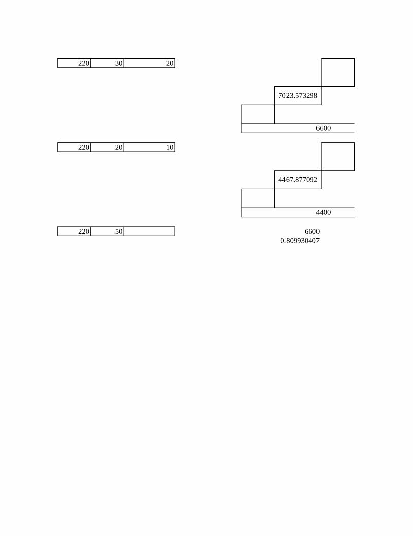
Lower limit kV -10% 360 198 99 29.7
Voltage kV 0% 400 220 110 33
Higher limit kV 10% 440 242 121 36.3
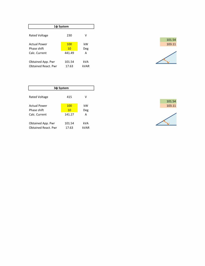
9.9 0.3735 0.216 0.099
11 0.415 0.24 0.11
12.1 0.4565 0.264 0.121
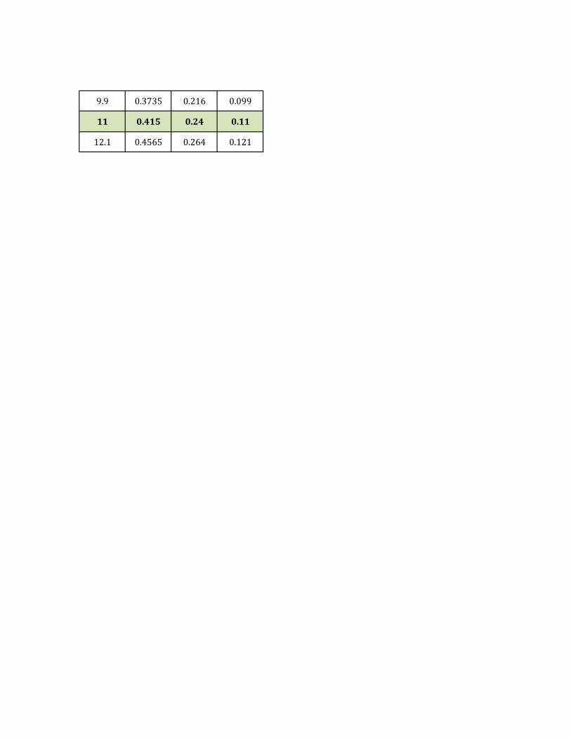
Rated Voltage 230 V
101.54
Actual Power 100 kW 103.11
Phase shift 10 Deg
Calc. Current 441.49 A
Obtained App. Pwr 101.54 kVA
Obtained React. Pwr 17.63 kVAR
Rated Voltage 415 V
101.54
Actual Power 100 kW 103.11
Phase shift 10 Deg
Calc. Current 141.27 A
Obtained App. Pwr 101.54 kVA
Obtained React. Pwr 17.63 kVAR
1φ System
3φ System

kVAR
17.63
17.63 kW
100.00
101.54 Cos (pi) 0.98 0.98
Tan (pi) 0.17 0.18
Sin (pi) 0.17 0.17
kVAR
17.63
17.63 kW
100.00
101.54 Cos (pi) 0.98 0.98
Tan (pi) 0.17 0.18
Sin (pi) 0.17 0.17
kVA
kVA
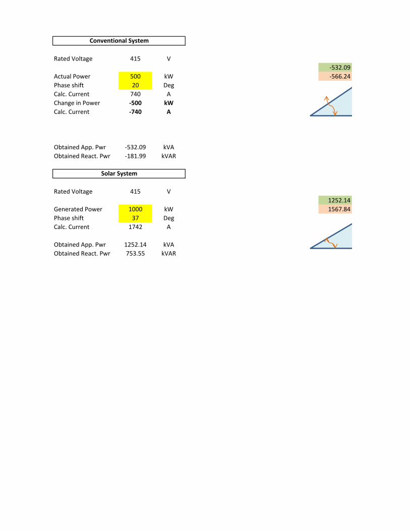
Rated Voltage 415 V
-532.09
Actual Power 500 kW -566.24
Phase shift 20 Deg
Calc. Current 740 A
Change in Power -500 kW
Calc. Current -740 A
Obtained App. Pwr -532.09 kVA
Obtained React. Pwr -181.99 kVAR
Rated Voltage 415 V
1252.14
Generated Power 1000 kW 1567.84
Phase shift 37 Deg
Calc. Current 1742 A
Obtained App. Pwr 1252.14 kVA
Obtained React. Pwr 753.55 kVAR
Conventional System
Solar System
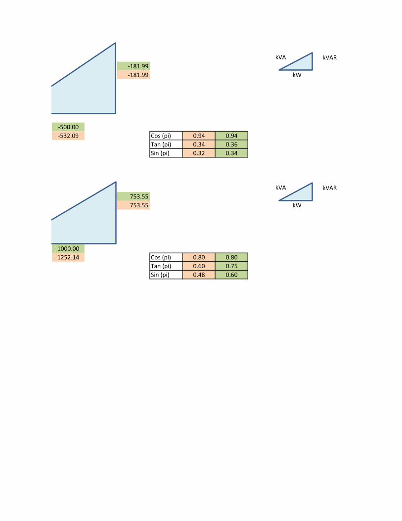
kVAR
-181.99
-181.99 kW
-500.00
-532.09 Cos (pi) 0.94 0.94
Tan (pi) 0.34 0.36
Sin (pi) 0.32 0.34
kVAR
753.55
753.55 kW
1000.00
1252.14 Cos (pi) 0.80 0.80
Tan (pi) 0.60 0.75
Sin (pi) 0.48 0.60
kVA
kVA
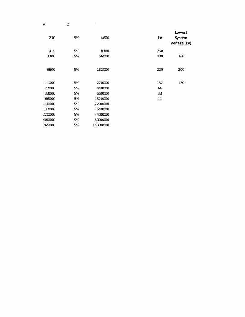
V Z I
230 5% 4600 kV
Lowest
System
Voltage (kV)
415 5% 8300 750
3300 5% 66000 400 360
6600 5% 132000 220 200
11000 5% 220000 132 120
22000 5% 440000 66
33000 5% 660000 33
66000 5% 1320000 11
110000 5% 2200000
132000 5% 2640000
220000 5% 4400000
400000 5% 8000000
765000 5% 15300000

Highest
System
Voltage (kV)
Variation of
Voltage (+-
%)
S/s Area
(Acre)
S/s Size
(m x m)Capacity (kVA) Bus Bar Scheme
800 Breaker and Half
420 Breaker and Half
245 12 -16 200 x 200
Double bus scheme
or Double main and
Transfer bus scheme
145 6 - 8 150 x 200 Double bus scheme
72.5 2 - 4 80 x 120
36 10
12 10
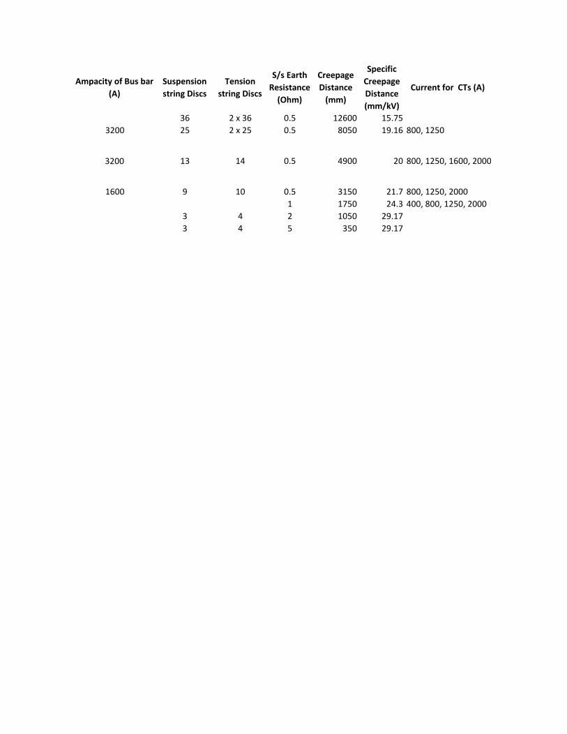
Ampacity of Bus bar
(A)
Suspension
string Discs
Tension
string Discs
S/s Earth
Resistance
(Ohm)
Creepage
Distance
(mm)
Specific
Creepage
Distance
(mm/kV)
Current for CTs (A)
36 2 x 36 0.5 12600 15.75
3200 25 2 x 25 0.5 8050 19.16 800, 1250
3200 13 14 0.5 4900 20 800, 1250, 1600, 2000
1600 9 10 0.5 3150 21.7 800, 1250, 2000
1 1750 24.3 400, 800, 1250, 2000
3 4 2 1050 29.17
3 4 5 350 29.17

Current for
CTs (A)
800, 1250, 1600, 2000

kV 750 400 220
Lowest System Voltage (kV) 360 200
Highest System Voltage (kV) 800 420 245
Variation of Voltage (+- %)
S/s Area (Acre) 12 -16
S/s Size (m x m) 200 x 200
Standard Bay Width (m) 27 17
Capacity (kVA)
Bus Bar Scheme Breaker and Half Breaker and Half
Double bus scheme or
Double main and
Transfer bus scheme
Bus Bar Material Moose (Quadraple)Moose (Single / Twin /
Quadraple)
Ampacity of Bus bar (A) 3200 3200
Suspension string Discs 36 25 13
Tension string Discs 2 x 36 2 x 25 14
S/s Earth Resistance (Ohm) 0.5 0.5 0.5
Full Wave Impulse Withstand Voltage
(1.2 / 50 micro sec.) kVp
1425 kVp for
substation 1550 kVp
for lines
900 - 1050
Switching impulse Withstand Voltage
(250 / 2500 ms) kVp1050 -
One minute Power Freq. withstand
voltage (rms) dry & wet (kV)
630 kV for substation
680 kVp for lines460
Corona Extinction Voltage (kV) 320 156
Max. Radio Interference Votage (RIV)
Betn 0.5 to 2 MHz at 267, 156 & 105
kVrms for 400, 220 & 132 kV
1000 micro volt 1000 micro volt
Min. Creepage Distance (mm) 12600 8050 4900
Total Creepage Distance (mm) 3800
Specific Creepage Distance (mm/kV) 15.75 19.16 20
Current for CTs (A) 800, 1250 800, 1250, 1600, 2000
Min. Clearances:
Phase to Phase (mm)
4200 mm for Rod
Type Conductor /
4000 mm for Cond to
Cond
2100
Phase to Earth (Sub station) (mm) 3500 2100
Sectional clearance (mm) 6500 5000
Equipment live terminal elevation (m) 8 4.9 - 5.5
Take-Off line elevation (m) 23 15 - 18.5
Live part to Tower Body under nil swing 3050 2130
Rated Short Ckt. Current for 1 Sec. (kA) 40 40
System Neutral EarthingEffectively
EarthedEffectively Earthed Effectively Earthed
Max. rated break time of CB's (ms) 40 60
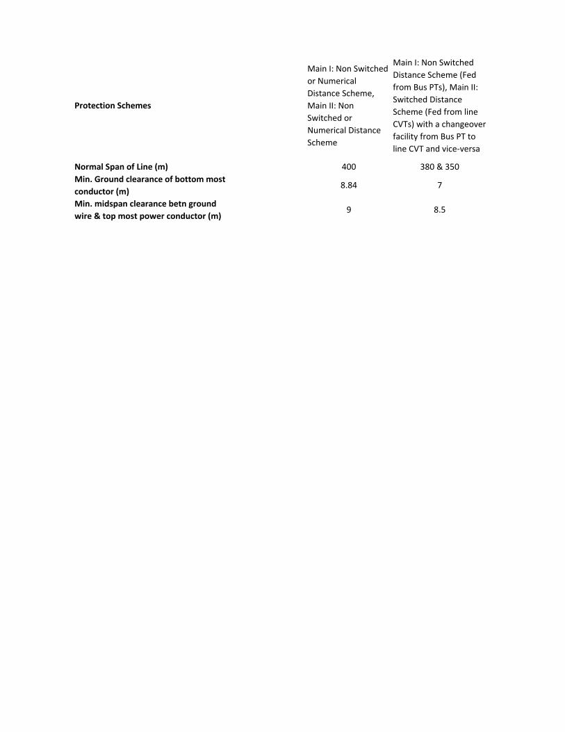
Protection Schemes
Main I: Non Switched
or Numerical
Distance Scheme,
Main II: Non
Switched or
Numerical Distance
Scheme
Main I: Non Switched
Distance Scheme (Fed
from Bus PTs), Main II:
Switched Distance
Scheme (Fed from line
CVTs) with a changeover
facility from Bus PT to
line CVT and vice-versa
Normal Span of Line (m) 400 380 & 350
Min. Ground clearance of bottom most
conductor (m)8.84 7
Min. midspan clearance betn ground
wire & top most power conductor (m)9 8.5
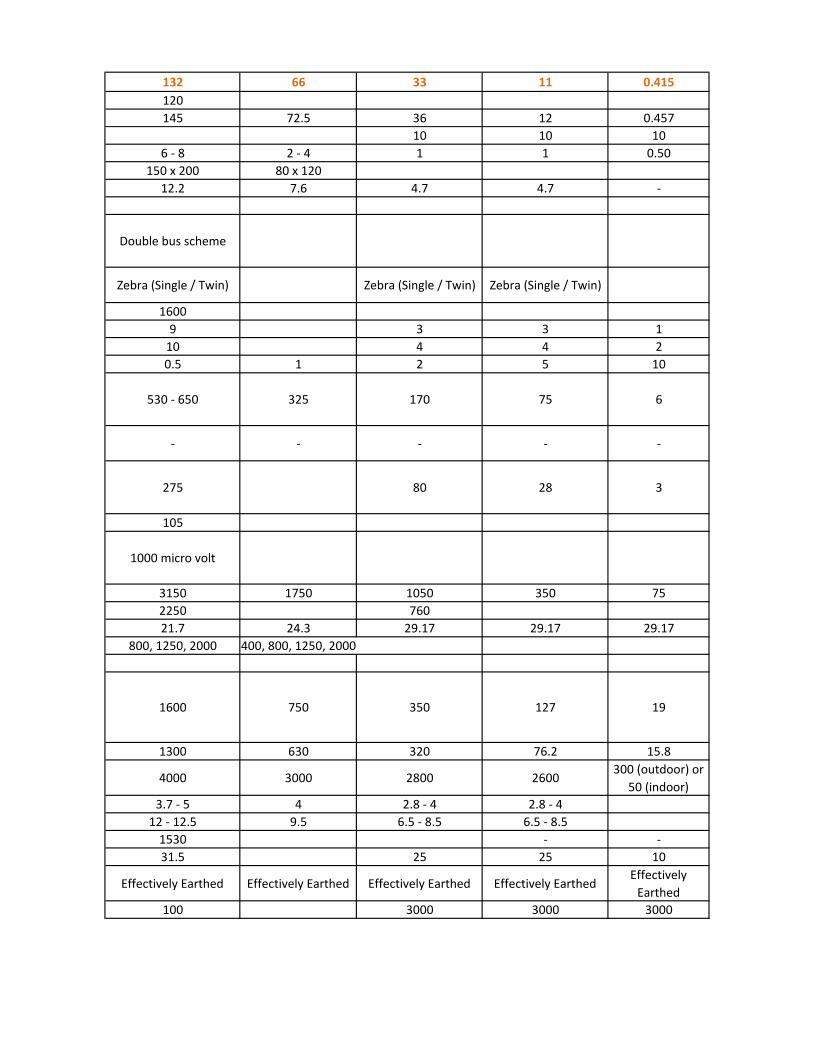
132 66 33 11 0.415
120
145 72.5 36 12 0.457
10 10 10
6 - 8 2 - 4 1 1 0.50
150 x 200 80 x 120
12.2 7.6 4.7 4.7 -
Double bus scheme
Zebra (Single / Twin) Zebra (Single / Twin) Zebra (Single / Twin)
1600
9 3 3 1
10 4 4 2
0.5 1 2 5 10
530 - 650 325 170 75 6
- - - - -
275 80 28 3
105
1000 micro volt
3150 1750 1050 350 75
2250 760
21.7 24.3 29.17 29.17 29.17
800, 1250, 2000 400, 800, 1250, 2000
1600 750 350 127 19
1300 630 320 76.2 15.8
4000 3000 2800 2600300 (outdoor) or
50 (indoor)
3.7 - 5 4 2.8 - 4 2.8 - 4
12 - 12.5 9.5 6.5 - 8.5 6.5 - 8.5
1530 - -
31.5 25 25 10
Effectively Earthed Effectively Earthed Effectively Earthed Effectively EarthedEffectively
Earthed
100 3000 3000 3000
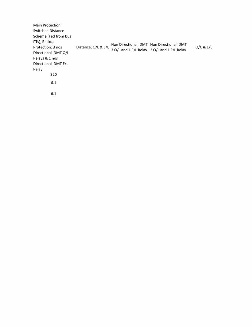
Main Protection:
Switched Distance
Scheme (Fed from Bus
PTs), Backup
Protection: 3 nos
Directional IDMT O/L
Relays & 1 nos
Directional IDMT E/L
Relay
Distance, O/L & E/LNon Directional IDMT
3 O/L and 1 E/L Relay
Non Directional IDMT
2 O/L and 1 E/L RelayO/C & E/L
320
6.1
6.1
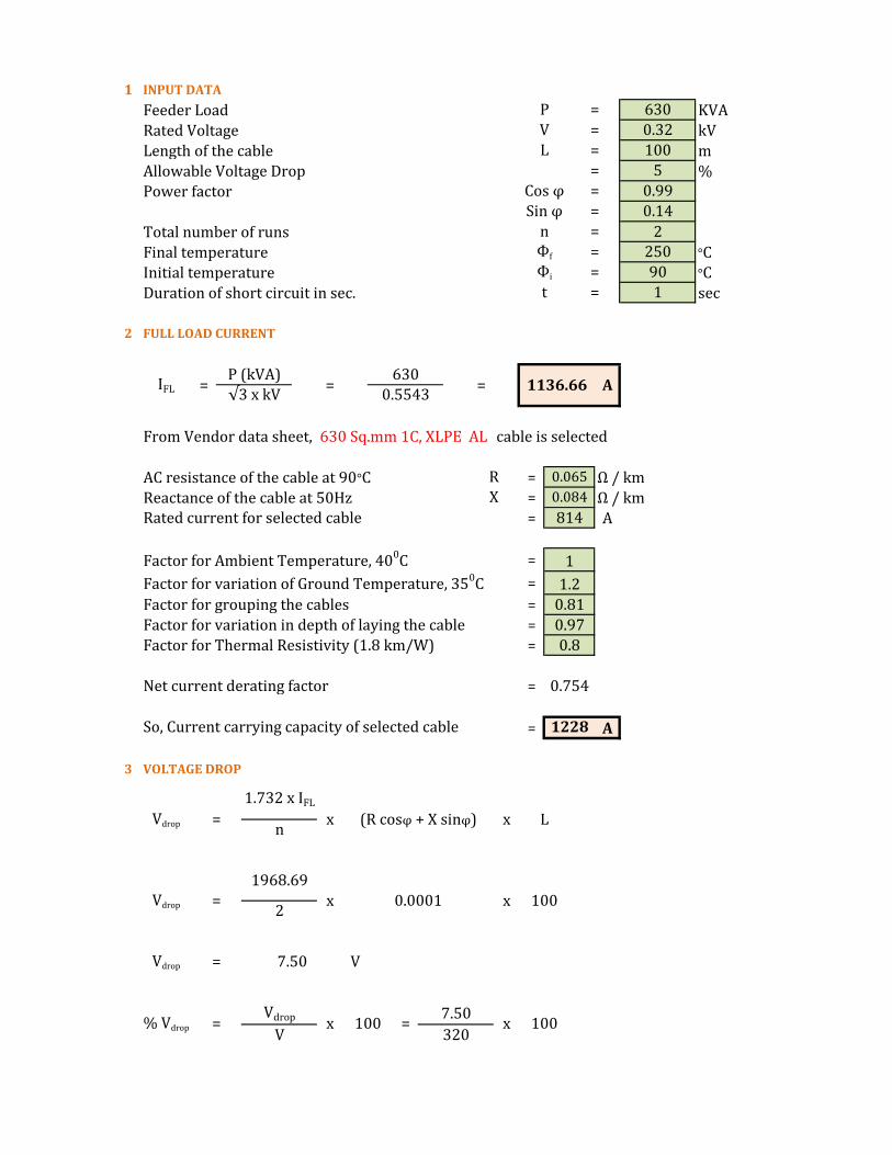
1 INPUT DATA
Feeder Load KVA
Rated Voltage kV
Length of the cable m
Allowable Voltage Drop %
Power factor
Total number of runs
Final temperature °C
Initial temperature °C
Duration of short circuit in sec. sec
2 FULL LOAD CURRENT
From Vendor data sheet, 630 Sq.mm 1C, XLPE AL cable is selected
AC resistance of the cable at 90°C = Ω / km
Reactance of the cable at 50Hz = Ω / kmRated current for selected cable = A
Factor for Ambient Temperature, 400C =
Factor for variation of Ground Temperature, 350C =
Factor for grouping the cables =
Factor for variation in depth of laying the cable =
Factor for Thermal Resistivity (1.8 km/W) =
Net current derating factor =
So, Current carrying capacity of selected cable = A
3 VOLTAGE DROP
t = 1
0.065
0.084
= 250Фi = 90
IFL =P (kVA)√3 x kV
=630
P = 630
V = 0.32
= 100
R
X
=Sin φ
= 5
=
L
n
0.5543= 1136.66
0.8
Cos φ =
1228
1.732 x IFL
Vdrop = x
814
1
1.2
0.81
0.97
0.99
0.14
2Фf
A
Vdrop = 7.50 V
n
1968.69
x 100
(R cosφ + X sinφ) x L
0.754
x 100320
Vdrop = x 0.0001
=Vdrop
V% Vdrop
1002
x
=7.50

The selected cable is in Permissible Voltage Drop
4 SHORT CIRCUIT CURRENT RATING OF CABLE Isc
(β + Фf)
(β + Фi)
5 REVERSE CALCULATION FOR C.S.A OF CABLE
6 EARTH FAULT CURRENT
A
Ief =134.4
1
Ief = 134.4
Sq.mm
Ief =A x K
√t
C.S.A =57960.00
92
C.S.A = 630
C.S.A =Isc x √t
Isc = 57960 A
Isc =57960
K
478
318ln
1
Isc =A x K x є
√tln
% Vdrop = 2.35 %
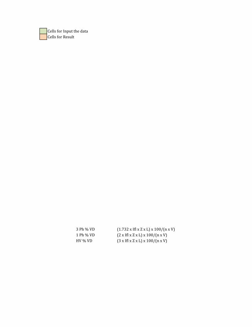
Cells for Input the data
Cells for Result
3 Ph % VD (1.732 x Ifl x Z x L) x 100/(n x V)
1 Ph % VD (2 x Ifl x Z x L) x 100/(n x V)
HV % VD (3 x Ifl x Z x L) x 100/(n x V)
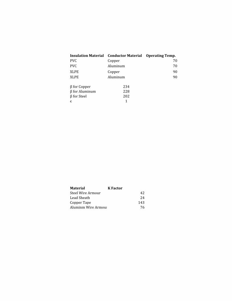
Insulation Material Conductor Material Operating Temp.
PVC Copper 70
PVC Aluminum 70
XLPE Copper 90
XLPE Aluminum 90
β for Copper 234β for Aluminum 228
β for Steel 202
є 1
Material K Factor
Steel Wire Armour 42
Lead Sheath 24Copper Tape 143
Aluminm Wire Armour 76


Short Ckt Temp. K Factor K Factor
160 115
160 76
250 143 226
250 92 148