Complete Equalization & Loudspeaker Management System Completo …… · Complete Equalization &...
69
User Manual/Manual de Instrucciones Complete Equalization & Loudspeaker Management System Completo sistema de ecualización y gestión de altavoces 240 241 ® ®
Transcript of Complete Equalization & Loudspeaker Management System Completo …… · Complete Equalization &...
User Manual/Manual de Instrucciones
Complete Equalization & Loudspeaker Management SystemCompleto sistema de ecualización y gestión de altavoces
240241
®
®
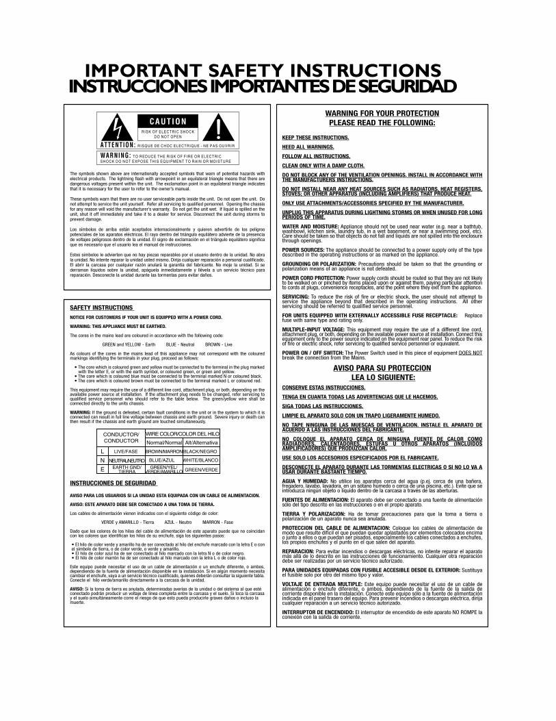
WARNING FOR YOUR PROTECTIONPLEASE READ THE FOLLOWING:
KEEP THESE INSTRUCTIONS.
HEED ALL WARNINGS.
FOLLOW ALL INSTRUCTIONS.
CLEAN ONLY WITH A DAMP CLOTH.
DO NOT BLOCK ANY OF THE VENTILATION OPENINGS. INSTALL IN ACCORDANCE WITHTHE MANUFACTURERS INSTRUCTIONS.
DO NOT INSTALL NEAR ANY HEAT SOURCES SUCH AS RADIATORS, HEAT REGISTERS,STOVES; OR OTHER APPARATUS (INCLUDING AMPLIFIERS) THAT PRODUCE HEAT.
ONLY USE ATTACHMENTS/ACCESSORIES SPECIFIED BY THE MANUFACTURER.
UNPLUG THIS APPARATUS DURING LIGHTNING STORMS OR WHEN UNUSED FOR LONGPERIODS OF TIME.
WATER AND MOISTURE: Appliance should not be used near water (e.g. near a bathtub,washbowl, kitchen sink, laundry tub, in a wet basement, or near a swimming pool, etc).Care should be taken so that objects do not fall and liquids are not spilled into the enclosurethrough openings.
POWER SOURCES: The appliance should be connected to a power supply only of the typedescribed in the operating instructions or as marked on the appliance.
GROUNDING OR POLARIZATION: Precautions should be taken so that the grounding orpolarization means of an appliance is not defeated.
POWER CORD PROTECTION: Power supply cords should be routed so that they are not likelyto be walked on or pinched by items placed upon or against them, paying particular attentionto cords at plugs, convenience receptacles, and the point where they exit from the appliance.
SERVICING: To reduce the risk of fire or electric shock, the user should not attempt toservice the appliance beyond that described in the operating instructions. All otherservicing should be referred to qualified service personnel.
FOR UNITS EQUIPPED WITH EXTERNALLY ACCESSIBLE FUSE RECEPTACLE: Replacefuse with same type and rating only.
MULTIPLE-INPUT VOLTAGE: This equipment may require the use of a different line cord,attachment plug, or both, depending on the available power source at installation. Connect thisequipment only to the power source indicated on the equipment rear panel. To reduce the riskof fire or electric shock, refer servicing to qualified service personnel or equivalent.
POWER ON / OFF SWITCH: The Power Switch used in this piece of equipment DOES NOTbreak the connection from the Mains.
AVISO PARA SU PROTECCION LEA LO SIGUIENTE:
CONSERVE ESTAS INSTRUCCIONES.
TENGA EN CUANTA TODAS LAS ADVERTENCIAS QUE LE HACEMOS.
SIGA TODAS LAS INSTRUCCIONES.
LIMPIE EL APARATO SOLO CON UN TRAPO LIGERAMENTE HUMEDO.
NO TAPE NINGUNA DE LAS MUESCAS DE VENTILACION. INSTALE EL APARATO DEACUERDO A LAS INSTRUCCIONES DEL FABRICANTE.
NO COLOQUE EL APARATO CERCA DE NINGUNA FUENTE DE CALOR COMORADIADORES, CALENTADORES, ESTUFAS U OTROS APARATOS (INCLUIDOSAMPLIFICADORES) QUE PRODUZCAN CALOR.
USE SOLO LOS ACCESORIOS ESPECIFICADOS POR EL FABRICANTE.
DESCONECTE EL APARATO DURANTE LAS TORMENTAS ELECTRICAS O SI NO LO VA AUSAR DURANTE BASTANTE TIEMPO.
AGUA Y HUMEDAD: No utilice los aparatos cerca del agua (p.ej. cerca de una bañera,fregadero, lavabo, lavadora, en un sótano húmedo o cerca de una piscina, etc.). Evite que seintroduzca ningún objeto o líquido dentro de la carcasa a través de las aberturas.
FUENTES DE ALIMENTACION: El aparato debe ser conectado a una fuente de alimentaciónsólo del tipo descrito en las instrucciones o en el propio aparato.
TIERRA Y POLARIZACION: Ha de tomar precauciones para que la toma a tierra opolarización de un aparato nunca sea anulada.
PROTECCION DEL CABLE DE ALIMENTACION: Coloque los cables de alimentación demodo que resulte difícil el que puedan quedar aplastados por elementos colocados encimao junto a ellos o que puedan ser pisados, especialmente los cables conectados a enchufes,los propios enchufes y el punto en el que salen del aparato.
REPARACION: Para evitar incendios o descargas eléctricas, no intente reparar el aparatomás allá de lo descrito en las instrucciones de funcionamiento. Cualquier otra reparacióndebe ser realizadas por un servicio técnico autorizado.
PARA UNIDADES EQUIPADAS CON FUSIBLE ACCESIBLE DESDE EL EXTERIOR: Sustituyael fusible solo por otro del mismo tipo y valor.
VOLTAJE DE ENTRADA MULTIPLE: Este equipo puede necesitar el uso de un cable dealimentación o enchufe diferente, o ambos, dependiendo de la fuente de la salida decorriente disponible en la instalación. Conecte este equipo sólo a la fuente de alimentaciónindicada en el panel trasero del equipo. Para prevenir incendios o descargas eléctrica, dirijacualquier reparación a un servicio técnico autorizado.
INTERRUPTOR DE ENCENDIDO: El interruptor de encendido de este aparato NO ROMPE laconexión con la salida de corriente.
SAFETY INSTRUCTIONSNOTICE FOR CUSTOMERS IF YOUR UNIT IS EQUIPPED WITH A POWER CORD.
WARNING: THIS APPLIANCE MUST BE EARTHED.
The cores in the mains lead are coloured in accordance with the following code:
GREEN and YELLOW - Earth BLUE - Neutral BROWN - Live
As colours of the cores in the mains lead of this appliance may not correspond with the colouredmarkings identifying the terminals in your plug, proceed as follows:
• The core which is coloured green and yellow must be connected to the terminal in the plug markedwith the letter E, or with the earth symbol, or coloured green, or green and yellow.
• The core which is coloured blue must be connected to the terminal marked N or coloured black.• The core which is coloured brown must be connected to the terminal marked L or coloured red.
This equipment may require the use of a different line cord, attachment plug, or both, depending on theavailable power source at installation. If the attachment plug needs to be changed, refer servicing toqualified service personnel who should refer to the table below. The green/yellow wire shall beconnected directly to the units chassis.
WARNING: If the ground is defeated, certain fault conditions in the unit or in the system to which it isconnected can result in full line voltage between chassis and earth ground. Severe injury or death canthen result if the chassis and earth ground are touched simultaneously.
INSTRUCCIONES DE SEGURIDAD
AVISO PARA LOS USUARIOS SI LA UNIDAD ESTA EQUIPADA CON UN CABLE DE ALIMENTACION.
AVISO: ESTE APARATO DEBE SER CONECTADO A UNA TOMA DE TIERRA.
Los cables de alimentación vienen indicados con el siguiente código de color:
VERDE y AMARILLO - Tierra AZUL - Neutro MARRON - Fase
Dado que los colores de los hilos del cable de alimentación de este aparato puede que no coincidancon los colores que identifican los hilos de su enchufe, siga los siguientes pasos:
• El hilo de color verde y amarillo ha de ser conectado al hilo del enchufe marcado con la letra E o conel símbolo de tierra, o de color verde, o verde y amarillo.• El hilo de color azul ha de ser conectado al hilo marcado con la letra N o de color negro.• El hilo de color marrón ha de ser conectado al hilo marcado con la letra L o de color rojo.
Este equipo puede necesitar el uso de un cable de alimentación o un enchufe diferente, o ambos,dependiendo de la fuente de alimentación disponible en la instalación. Si en algún momento necesitacambiar el enchufe, vaya a un servicio técnico cualificado, quienes deberán consultar la siguiente tabla.Conecte el hilo verde/amarillo directamente a la carcasa de la unidad.
AVISO: Si la toma de tierra es anulada, determinadas averías de la unidad o del sistema al que estéconectado podrán producir un voltaje de línea completa entre la carcasa y el suelo. Si toca la carcasay el suelo simultáneamente corre el riesgo de que esto pueda producirle graves daños o incluso lamuerte.
LIVE/FASE
E
NEUTRAL/NEUTROEARTH GND/
TIERRA
CONDUCTOR/CONDUCTOR
L
N
BROWN/MARRON
BLUE/AZUL
GREEN/YEL/VERDE/AMARILLO
BLACK/NEGRO
Normal/Normal Alt/Alternativa
WIRE COLOR/COLOR DEL HILO
WHITE/BLANCO
GREEN/VERDE
The symbols shown above are internationally accepted symbols that warn of potential hazards withelectrical products. The lightning flash with arrowpoint in an equilateral triangle means that there aredangerous voltages present within the unit. The exclamation point in an equilateral triangle indicatesthat it is necessary for the user to refer to the owner’s manual.
These symbols warn that there are no user serviceable parts inside the unit. Do not open the unit. Donot attempt to service the unit yourself. Refer all servicing to qualified personnel. Opening the chassisfor any reason will void the manufacturer’s warranty. Do not get the unit wet. If liquid is spilled on theunit, shut it off immediately and take it to a dealer for service. Disconnect the unit during storms toprevent damage.
Los símbolos de arriba están aceptados internacionalmente y quieren advertirle de los peligrospotenciales de los aparatos eléctricos. El rayo dentro del triángulo equilátero advierte de la presenciade voltajes peligrosos dentro de la unidad. El signo de exclamación en el triángulo equilátero significaque es necesario que el usuario lea el manual de instrucciones.
Estos símbolos le advierten que no hay piezas reparables por el usuario dentro de la unidad. No abrala unidad. No intente reparar la unidad usted mismo. Dirija cualquier reparación a personal cualificado.El abrir la carcasa por cualquier razón anulará la garantía del fabricante. No moje la unidad. Si sederraman líquidos sobre la unidad, apáguela inmediatamente y llévela a un servicio técnico parareparación. Desconecte la unidad durante las tormentas para evitar daños.
C A U T IO N
ATTENT ION: RISQUE DE CHOC ELECTRIQUE - NE PAS OUVRIR
WARNING: TO REDUCE THE R ISK OF F IRE OR ELECTRICSHOCK DO NOT EXPOSE TH IS EQUIPMENT TO RA IN OR MOISTURE
RISK OF ELECTRIC SHOCKDO NOT OPEN
IMPORTANT SAFETY INSTRUCTIONSINSTRUCCIONES IMPORTANTES DE SEGURIDAD
U.K. MAINS PLUG WARNING
A molded mains plug that has been cut off from the cord isunsafe. Discard the mains plug at a suitable disposal facility.NEVER UNDER ANY CIRCUMSTANCES SHOULD YOU INSERTA DAMAGED OR CUT MAINS PLUG INTO A 13 AMP POWERSOCKET. Do not use the mains plug without the fuse cover inplace. Replacement fuse covers can be obtained from yourlocal retailer. Replacement fuses are 13 amps and MUST beASTA approved to BS1362.
ADVERTENCIA PARA LOS USUARIOS DEL REINOUNIDO
Un enchufe de alimentación que haya sido cortado del cablees inseguro. Nunca utilice cables montados de esta forma pormedio de distintos enchufes y cables no originales. BAJONINGUNA CIRCUNSTANCIA INTRODUZCA UN CONECTOR OCABLE DAÑADO O CORTADO EN UN ENCHUFE DE 13AMPERIOS. No use el conector de alimentación sin la tapa delfusible en su lugar. Puede adquirir tapas de fusible derecambio en su tienda de electricidad más próxima. Losfusibles son de 13 amperios y DEBEN de estar aprobados porla ASTA a BS1362.
LITHIUM BATTERYWARNING
CAUTION!This product may contain a lithium battery.There is danger ofexplosion if the battery is incorrectly replaced. Replace onlywith an Eveready CR 2032 or equivalent. Make sure thebattery is installed with the correct polarity. Discard usedbatteries according to manufacturer’s instructions.ADVARSEL!Lithiumbatteri - Eksplosjonsfare.Ved utskifting benyttes kunbatteri som anbefalt av apparatfabrikanten. Brukt batterireturneres apparatleverandøren.ADVARSEL!Lithiumbatteri - Eksplosionsfare ved fejlagtig håndtering.Udskiftning må kun ske med batteri av samme fabrikat ogtype. Levér det brugte batteri tilbage til leverandøren.VAROITUS!Paristo voi räjähtää, jos se on virheellisesti asennettu.Vaihdaparisto ainoastaan laitevalmistajan suosittelemaan tyyppin.Hävitä käytetty paristo valmistajan ohjeiden mukaisesti.VARNING!Explosionsfara vid felaktigt batteribyte.Använd sammabatterityp eller en ekvivalent typ som rekommenderas avapparattillverkaren. Kassera använt batteri enligt fabrikantensinstruktion.
IMPORTANT SAFETY INSTRUCTIONSINSTRUCCIONES IMPORTANTES DE SEGURIDAD
ELECTROMAGNETICCOMPATIBILITY
This unit conforms to the Product Specifications noted on the
Declaration of Conformity. Operation is subject to the following two
conditions:• this device may not cause harmful interference, and • this device must accept any interference received, including
interference that may cause undesired operation.Operation of this unit within significant electromagnetic fields should beavoided.
• use only shielded interconnecting cables.
COMPATIBILIDADELECTROMAGNETICA
Esta unidad cumple las Especificaciones de Producto indicadas en la
Declaración de Conformidad. Su funcionamiento está sujeto a las dos
condiciones siguientes:
• este aparato no puede causar interferencias dañinas, y
• este aparato debe aceptar cualquier interferencia recibida,
incluyendo interferencias que puedan provocar un funcionamiento
no deseado.
Evite el funcionamiento de esta unidad dentro de campos
electromagnéticos potentes.
• use sólo cables de interconexión blindados.
DECLARATION OF
CONFORMITY
Manufacturer’s Name: dbx Professional Products
Manufacturer’s Address: 8760 S. Sandy Parkway
Sandy, Utah 84070, USA
declares that the product:
Product name: dbx DriveRack™ 240 and 241
Note: product may be suffixed by the letters EU.
Product option: None
conforms to the following Product Specifications:
Safety: EN 60065 (1993)
IEC65 (1985) with
Amendments 1,2,3
CAN/CSA E65-94
EMC: EN 55013 (1990)
EN 55020 (1991)
Supplementary Information:
The product herewith complies with the
requirements of the Low Voltage Directive
73/23/EEC and the EMC Directive 89/336/EEC as
amended by Directive 93/68/EEC.
dbx Professional Products
Vice-President of Engineering
8760 S. Sandy Parkway
Sandy, Utah 84070, USA
February 8, 2001
European Contact: Your Local dbx Sales and Service Office or
Harman Music Group
8760 South Sandy Parkway Sandy, Utah 84070
USA
PH: (801) 566-8800 FX: (801) 568-7583
CONFORMIDAD
Nombre del fabricante: dbx Professional Products
Dirección del fabricante: 8760 S. Sandy Parkway
Sandy, Utah 84070, USA
Declara que el producto:
Nombre del producto: dbx DriveRack™ 240 and 241
Nota: product may be suffixed by the letters EU.
Opción del producto: None
Cumple las siguientes Especificaciones de Producto:
Seguridad: EN 60065 (1993)
IEC65 (1985) with
Amendments 1,2,3
CAN/CSA E65-94
EMC: EN 55013 (1990)
EN 55020 (1991)
Información complementaria:
El producto cumple con los requisitos de la
Directiva de Baja Tensión 73/23/EEC y la
Directiva EMC 89/336/EEC enmendada por la
Directiva 93/68/EEC.
dbx Professional Products
Vicepresidente técnico
8760 S. Sandy Parkway
Sandy, Utah 84070, USA
February 8, 2001
Contacto en Europa: Su vendedor local dbx y servicio técnico oficial o
Harman Music Group
8760 South Sandy Parkway Sandy, Utah 84070
USA
Tfno: (801) 566-8800 FX: (801) 568-7583
Table of Contents/IndiceDriveRack™
Introduction/Introducción
0.1 Defining the 240/241DriveRack™/Definición del Sistema 240/241DriveRack™..ii
0.2 Service Contact Info/Información de contacto para reparaciones ..iii
0.3 Warranty/Garantía ...............................................................................iv
0.4 Quick Start/Arranque rápido...............................................................v
Section 1 - Getting Started/Sección 1 - Inicio
1.1 Rear Panel Connections (240)/Conexiones del panel trasero (240) 2
1.2 Front Panel (240)/Panel frontal (240) ...............................................2
1.3 Rear Panel Connections (241)/Conexiones del panel trasero (241) 3
1.4 Front Panel (241)/Panel frontal (241) ...............................................4
Section 2 - Editing Functions/Sección 2 - Funciones de Edición
2.1 Basic Navigation Modes/Modos básicos de navegación...................6
2.2 Button Array Overview/Disposición de los botones.........................6
2.3 Navigating the Pre-EQ Section/Navegación por la sección pre-ecualizador.8
2.4 Navigating the Post-EQ Section/Navegación por la sección post-ecualizador.8
2.5 Navigating the Xover Sections/Navegación por las secciones de crossover.9
2.6 Navigating the Delay Section/Navegación por la sección de retardo..........9
2.7 Navigating the Dynamics Section/Navegación por la sección de dinamismo10
2.8 Navigating the I/O Section/Navegación por la sección de E/S......10
2.9 Navigating the Utility Section/Navegación por la sección de utilidades10
Section 3- Configuring the DriveRack/Sección3- Configuración del DriveRack
3.1 Program Definition/Definición de programa ...................................12
3.2 Navigating Factory Programs/Navegación por los programas de fábrica...12
3.3 Editing Factory Programs/Edición de los programas de fábrica ....13
3.4 Saving Factory Program Changes/Almacenamiento de los cambios sobre
los programas de fábrica .................................................................................14
3.5 Creating a User Configuration/Creación de una configuración de usuario15
3.6 Saving Configuration Changes/Almacenamiento de cambios de configuración18
Section 4 - Detailed Parameters/Sección 4 - Parámetros detallados
4.1 Input Routing/Direccionamiento de entrada ...................................20
4.2. Pre-Crossover EQ/Pre-Crossover (ecualización).................................................................20
4.3 Delay (Pre-Crossover)/Retardo (Pre-Crossover) ..............................21
4.4 Crossover (XOVER)/Crossovers (XOVER)........................................22
4.5 Post-Crossover Parametric EQ/Ecualizador paramétrico post-crossover.....26
4.6 Compressor/Limiter (Dynamics)/Compresor / limitador (dinamismo)26
4.7 Speaker Alignment Delay/Retardo de alineación de altavoces ......28
4.8 OutputRouting/Salida.........................................................................28
Section 5 - Utilities/Sección 5 - Utilidades
5.1 Security Levels/Niveles de seguridad ...............................................30
5.2 Security Passwords/Contraseña de seguridad..................................31
5.3 Entering Security Password/Introducción de la contraseña de seguridad..31
5.4 Program Change/Program list/Lista de programas / cambio de programa32
5.5 Contrast Adjustment/Ajuste de contraste..........................................33
5.6 Power-up (Mutes/Saved)/Encendido (anulación / grabación) .......34
5.7 Load Stored/Carga almacenada.........................................................34
5.8 Switch Closure option/Opción de cierre de interruptor .................35
Section 6 - DriveWare™ GUI/Sección 6 - DriveWare™ GUI
6.1 PC GUI Installation/Instalación GUI.................................................38
System Requirements/Requisitos del sistema.........................................38
Install/Instalación .....................................................................................38
Basic operation/Funcionamiento básico.................................................38
Cable specs/Especificaciones de los cables ...........................................40
Section 7 - Application Guide/Sección 7 - Guía de aplicación
7.1 2-Way FOH/FOH de dos vías ...........................................................42
7.2 2x4 Delay Cabinets/Recintos 2x4 con retardo.................................43
7.3 L-C-R w/Sub/Izquierdo-central-derecho + subwoofer ....................44
7.4 Multi-Zone Controller/Controlador multizonas................................45
7.5 Time Delay/Retardo de tiempo ........................................................46
7.6 Programmable Insert/Inserción programable...................................47
7.7 Single Room Multi-Zone/Multizonas en sala única .........................48
Appendix/Apéndices
A.1 Factory Reset/Reinicialización a los valores de fábrica ..................50
A.2 Power up Quick Key Options/Opciones de teclas rápidas para el encendido50
A.3 Flash Downloads/Volcados rápidos .................................................51
A.4 Program List/Lista de programas......................................................51
A.5 Specifications/Especificaciones.........................................................52
A.6 Crossover Diagrams/Diagramas de crossover .................................55
A.7 Gain Level Jumpers/Puentes de nivel de ganacia ..........................56
A.8 Input and Output Section Diagrams/Diagramas de sección de entrada y salida57
®
DriveRack™ User Manual/ Manual de InstruccionesTable of Contents/Table of Contents
INTROCUSTOMER SERVICE INFO
Defining the DriveRackWARRANTY INFO
INTROINFORMACION DE CONTACTO
PARA REPARACIONESDefinición del DriveRack
GARANTIA
®
INTRODUCTION/INTRODUCCIONDriveRack™
Section i/Sección i
Introduction/Introducción
®
DriveRack™ User Manual/Manual de Instruccionesii
DriveRack™
Congratulations on your purchase of the dbx 240/241DriveRack™Complete Equalization and Loudspeaker Management System! For over 25years, dbx has been the industry leader in dynamics processing. With theintroduction of the DriveRack™, dbx Professional Products has redefinedthe standard by which all other loudspeaker management systems will bebased.
This manual will be your guide to understanding the full functionality ofthe powerful 240 and 241 DriveRack™ units. By combining the differentcomponents, the configuration possibilities are limitless. After you havebecome familiar with the unit, we encourage you to experiment and findthe most effective and efficient way to run your system by utilizing thepowerful processing of the DriveRack™.
The dbx 240/241 DriveRack™ is the most effective way to manage allaspects of post mixer processing and signal routing. The 240/241DriveRack essentially becomes the only device that you will needbetween the mixer and the power amps. The following are just some of
the features of the 240 and 241 DriveRack™ units.
240 DriveRack™ features:• 2 Inputs and 4 Outputs
• Fully functional user interface
• Balanced XLR and Euroblock Connectors
• 31-band graphic or 9-band parametric equalizer on every input
• Multiple Crossover Configurations including Butterworth,
Bessel or Linkwitz-Riley filter topologies
• Loudspeaker Cluster and Transducer Alignment Delays
• 4-band Parametric EQ Post crossover per output. Selectable
shelves or bell curves. 1/12 octave centers, Q selectable from
0.20 to 16.
• dbx®
Compression/Limiting
• Multi-level Security System
• Patented dbx®
TYPE IV® Analog to Digital Conversion System
• PC DriveWare Interface
• Remote Switch Closure Interface
241 DriveRack™ features:• 2 Inputs and 4 Outputs
• Balanced XLR and Euroblock Connectors
• 31-band graphic or 9-band parametric equalizer on every input
• Multiple Crossover Configurations including Butterworth,
Bessel or Linkwitz-Riley filter topologies
• Loudspeaker Cluster and Transducer Alignment Delays
• 4-band Parametric EQ Post crossover per output. Selectable
shelves or bell curves. 1/12 octave centers, Q selectable from
0.20 to 16.
¡Felicidades por la compra del sistema completo de ecualización y gestiónde altavoces dbx DriveRack™ 240/241! Desde hace 25 años, dbx ha sidola empresa líder en el campo del procesado dinámico. Con lapresentación del DriveRack™, dbx Professional Products ha redefinido elstandard de referencia para los sistemas de gestión de altavoces.
Este manual le ayudará a comprender toda la funcionalidad de laspotentes unidades 240 y 241 DriveRack™. Combinando los distintoscomponentes, las posibilidades de configuración son infinitas. Una vezque se haya familiarizado con la unidad, le recomendamos que haga suspropias pruebas y encuentre la forma más efectiva y directa de hacerfuncionar su sistema utilizando el potente procesado del DriveRack™.
El dbx DriveRack™ es la forma más eficaz de gestionar todos los aspectosdel procesado post-mezcla y del direccionamiento de señal. El DriveRack240/241 se convierte esencialmente en el único aparato que necesitaráentre la mesa de mezclas y sus etapas de potencia. A continuación le
indicamos algunas de las funciones de las unidades DriveRack™ 240 y 241.
Características del 240 DriveRack™ :• 2 entradas and 4 salidas
• Interface de usuario completamente funcional
• Conectores XLR y Euroblock balanceados
• Ecualizador gráfico de 31bandas o paramétrico de 9 bandas en
cada entrada
• Múltiples configuraciones de crossover incluyendo tipologías
de filtro Butterworth, Bessel o Linkwitz-Riley
• Retardos de alineación de transductor y bloque central de altavoces
• EQ paramétrico de 4 bandas post-crossover por salida. Curvas
de estantería o de tipo campana seleccionables con centros en
1/12 de octava, Q seleccionable desde 0.20 a 16
• Compresor/Limitador dbx®
• Sistema de seguridad multinivel
• Sistema de conversión analógico a digital TYPE IV™ patentado por dbx
• Interface DriveWare PC
• Interface de cierre de interruptor a distancia
Características del 241 DriveRack™:• 2 entradas and 4 salidas
• Conectores XLR y euroblock balanceados
• Ecualizador gráfico de 31bandas o paramétrico de 9 bandas en
cada entrada
• Múltiples configuraciones de crossover incluyendo tipologías
de filtro Butterworth, Bessel o Linkwitz-Riley
• Retardos de alineación de transductor y bloque central de
altavoces
• EQ paramétrico de 4 bandas post-crossover por salida. Curvas
de estantería o de tipo campana seleccionables con centros en
1/12 de octava, Q seleccionable desde 0.20 a 16
INTRODUCTION
0.1 Defining the 240/241 DriveRack™ System 0.1 0.1 Definición del Sistema DriveRack™ 240/241
INTRODUCCION
Section i/Sección i
®
Introduction/IntroducciónDriveRack™
DriveRack™ User Manual/Manual de Instrucciones
• dbx®
Compression/Limiting
• Multi-level Security System
• Patented dbx®
TYPE IV™ Analog to Digital Conversion System
• PC DriveWare Interface
• Remote Switch Closure Interface
By including every form of processing necessary to drive the signal fromthe mixer to the power amp, the 240/241 DriveRack™ allows you toeliminate all other processing devices that are normally found in large andcumbersome traditional drive rack systems of the past.
The 240/241 DriveRack™ Loud Speaker Management System includes twobalanced XLR and Euroblock inputs, as well as four balanced XLR andEuroblock output connectors, which can be routed for any configuration.The 241 DriveRack™ features the identical processing power of the 240DriveRack, but only offers limited editing functionality from the front
panel.
If you require technical support, contact dbx Customer Service. Beprepared to accurately describe the problem. Know the serial number ofyour unit - this is printed on a sticker attached to the top panel. If youhave not already taken the time to fill out your warranty registration cardand send it in, please do so now.
Before you return a product to the factory for service, we recommend yourefer to the manual. Make sure you have correctly followed installationsteps and operation procedures. If you are still unable to solve a problem,contact our Customer Service Department at (801) 568-7660 forconsultation. If you need to return a product to the factory for service,you MUST contact Customer Service to obtain a Return AuthorizationNumber.
No returned products will be accepted at the factory without a ReturnAuthorization Number.
Please refer to the Warranty information on the following page, whichextends to the first end-user. After expiration of the warranty, areasonable charge will be made for parts, labor, and packing if youchoose to use the factory service facility. In all cases, you are responsiblefor transportation charges to the factory. dbx will pay return shipping ifthe unit is still under warranty.
Use the original packing material if it is available. Mark the package withthe name of the shipper and with these words in red: DELICATEINSTRUMENT, FRAGILE! Insure the package properly. Ship prepaid, notcollect. Do not ship parcel post.
• Compresor/Limitador dbx®
• Sistema de seguridad multinivel
• Sistema de conversión analógico a digital TYPE IV™ patentado por dbx
• Interface DriveWare PC
• Interface de cierre de interruptor a distancia
Al incluir todas las formas de procesado necesarias para el control de laseñal desde el mezclador hasta la etapa de potencia, los DriveRack™240/241 le permiten prescindir del resto de unidades de procesado quese encontraban normalmente en uno de esos gigantescos e incómodossistemas de unidades de control en rack tradicionales hace algunos años.
El sistema de gestión de altavoces DriveRack™ 240/241 incluye dosentradas balanceadas XLR y euroblock, así como cuatro salidasbalanceadas XLR y euroblock, que pueden ser direccionadas en cualquierconfiguración. El DriveRack™ 241 disponen del mismo potencial deprocesado que el del 240, pero le ofrece unas funciones de edición algomás limitadas desde su panel frontal.
Si necesita asistencia técnica, contacte con el Servicio de Atención alCliente dbx. Esté preparado para describir con precisión el problema.Debe saber el número de serie de su unidad – está impreso en unapegatina colocada en el panel trasero. Si todavía no ha rellenado su tarjetade registro de garantía y no la ha enviado, hágalo ahora.
Antes de devolver un aparato a fábrica para su reparación, lerecomendamos que consulte este manual. Asegúrese de haber seguidocorrectamente los pasos de instalación y los procesos operativos. Si aunasí es incapaz de solucionar el problema, contacte con nuestroDepartamento de Servicio de Atención al Cliente en el (801) 568-7660. Sinecesita devolver un aparato a fábrica para su reparación, DEBERAcontactar con nuestro Servicio de Atención al Cliente para que le asignenun Número de autorización de devolución.
En fábrica no aceptaremos ningún aparato sin su correspondiente númerode autorización de devolución.
Consulte la garantía siguiente, que cubre al primer usuario final. Tras elvencimiento de esta garantía, en cualquier reparación que hagamos enfábrica tendremos que cobrarle las piezas, mano de obra y el embalaje.Sea cual sea el caso, deberá enviar el aparato a fábrica a portes pagados.dbx se lo devolverá también a portes pagados si la unidad está todavíaen garantía.
Utilice el embalaje original siempre que sea posible. Marque el embalajecon el nombre del transportista y con estas palabras en rojo:INSTRUMENTO DELICADO ¡FRAGIL!. Es recomendable que contrate unseguro de transporte. Envíe el paquete a portes pagados, no debidos. No
lo envíe por correo.
iii
0.2 Service Contact Info 0.2 Información de contacto para reparaciones
Section i/Sección i
Introduction/Introducción
®
DriveRack™ User Manual/Manual de Instruccionesiv
DriveRack™
This warranty is valid only for the original purchaser and only in theUnited States.
1. The warranty registration card that accompanies this product must bemailed within 30 days after purchase date to validate this warranty.Proof-of-purchase is considered to be the burden of the consumer.
2. dbx warrants this product, when bought and used solely within theU.S., to be free from defects in materials and workmanship undernormal use and service.
3. dbx liability under this warranty is limited to repairing or, at ourdiscretion, replacing defective materials that show evidence of defect,provided the product is returned to dbx WITH RETURNAUTHORIZATION from the factory, where all parts and labor will becovered up to a period of two years. A Return Authorization numbermust be obtained from dbx by telephone. The company shall not beliable for any consequential damage as a result of the product's use inany circuit or assembly.
4. dbx reserves the right to make changes in design or make additions toor improvements upon this product without incurring any obligation toinstall the same additions or improvements on products previouslymanufactured.
5. The foregoing is in lieu of all other warranties, expressed or implied,and dbx neither assumes nor authorizes any person to assume on itsbehalf any obligation or liability in connection with the sale of thisproduct. In no event shall dbx or its dealers be liable for special orconsequential damages or from any delay in the performance of thiswarranty due to causes beyond their control.
Todos los aparatos dbx son fabricados con el máximo cuidado. Lascondiciones de la garantía varían desde el momento en que losdistribuidores son distintos en cada país.Si necesita cualquier información relacionada con las condiciones de lagarantía en su país, le rogamos que se ponga en contacto con sudistribuidor o comercio local
dbx es una marca registrada.
NOTA: La información contenida en este manual está sujeta a cambios encualquier momento sin previo aviso. Algunas de las informacionescontenidas en este manual pueden incluso ser inexactadas debido amodificaciones no documentadas en el aparato o en el sistema operativodesde el momento de finalizar esta versión del manual. La informacióncontenida en este manual de instrucciones sustituye a la de versionesanteriores.
0.3 Warranty 0.3 Garantía
Section i/Sección i
®
For those of you that wish to jump right in, the following information has
been provided to act as a quick start guide for optimizing performance of
the 240/241 DriveRack units.
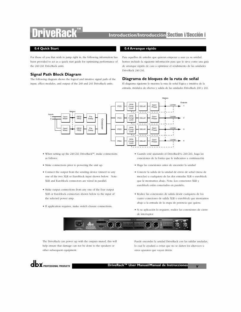
Signal Path Block DiagramThe following diagram shows the logical and intuitive signal path of the
input, effect modules, and output of the 240 and 241 DriveRack units.
• When setting up the 240/241 DriveRack™, make connections
as follows:
• Make connections prior to powering the unit up.
• Connect the output from the sending device (mixer) to any
one of the two XLR or Euroblock input shown below. Note:
XLR and Euroblock connectors are wired in parallel.
• Make output connections from any one of the four output
XLR or Euroblock connectors shown below to the input of
the selected power amp.
• If application requires, make switch closure connections.
The DriveRack can power up with the outputs muted, this will
help ensure that damage can not be done to the speakers or
other subsequent equipment.
Para aquellos de ustedes que quieran empezar a usar ya su unidad,
hemos incluido la siguiente información para que le sirva como una guía
de arranque rápido de cara a optimizar el rendimiento de las unidades
DriveRack 240/241.
Diagrama de bloques de la ruta de señalEl diagrama siguiente le muestra la ruta de señal lógica e intuitiva de la
entrada, módulos de efectos y salida de las unidades DriveRack 240 y 241.
• Cuando esté ajustando el DriveRack‰ 240/241, haga las
conexiones de la forma que le indicamos a continuación
• Haga las conexiones antes de encender la unidad
• Conecte la salida de la unidad de envío de señal (mesa de
mezclas) a cualquiera de las dos entradas XLR o euroblock
que le mostramos abajo. Nota: Los conectores XLR y
euroblock están conectados en paralelo.
• Realice las conexiones de salida desde cualquiera de los
cuatro conectores de salida XLR o euroblock que mostramos
abajo a la entrada de la etapa de potencia que quiera.
• Si su aplicación lo requiere, realice las conexiones de cierre
de interruptor
Puede encender la unidad DriveRack con las salidas anuladas,
lo cual le ayudará a evitar que no se dañen los altavoces u
otros aparatos que vayan detrás.
Introduction/Introducción Section i/Sección iDriveRack™
DriveRack™ User Manual/Manual de Instrucciones v
0.4 Quick Start 0.4 Arranque rápido
InputMixer
InputMixer
GEQ/PEQ
GEQ/PEQ
PreDelay
PreDelay
PEQ
Meters
Inputs12
Outputs
1
2
3
4
Gain/Phase
Gain/Phase
Gain/Phase
Gain/Phase
Cro
ssove
r
PEQ
PEQ
PEQ
DYNComp/Limit
DYNComp/Limit
DYNComp/Limit
DYNComp/Limit
DELAY
DELAY
DELAY
DELAY
Meters
Limiter
Limiter
Limiter
Limiter
Introduction/Introducción
®
DriveRack™ User Manual/Manual de Instruccionesvi
Section i/Sección i DriveRack™
Front Panel Navigation of the 240DriveRack
• Once all of the connections have been made and the unit is
powered up you can navigate through the entire signal path
of the 240 DriveRack from the front panel of the unit. The
display provides you with a clear and concise overview of
each aspect of the signal path from the input to the output
section.
The features of the front panel of the 240 DriveRack are as
follows from left to right. LCD Display- all operational
information of the DriveRack is displayed here. The display
will also notify the user if any internal clipping is taking place
within the unit. The following messages will appear: CLIP:
Pre Xover (clipping prior to the crossover section), CLIP:
Post Xover (clipping past the crossover section), and CLIP:
Pre/Post (clipping in both sections).
Data Wheel - The data wheel is used to scroll through the
program menu of the 240 DriveRack™. The Data Wheel is also
used to perform editing functions to effects and utility menu
features. Button Array - Operational editing is done using this
12 button array. A complete description of each button’s
functionality is listed on the following page. Input meters-These two 6-segment LED meters monitor the input level of
the 240 DriveRack directly after the input mixer. Outputmeters - These four 6-segment meters monitor the output
levels of the 240 DriveRack directly after the output gain stage.
Mute buttons - These four mute buttons are used to instantly
mute the output signal of the selected channel.
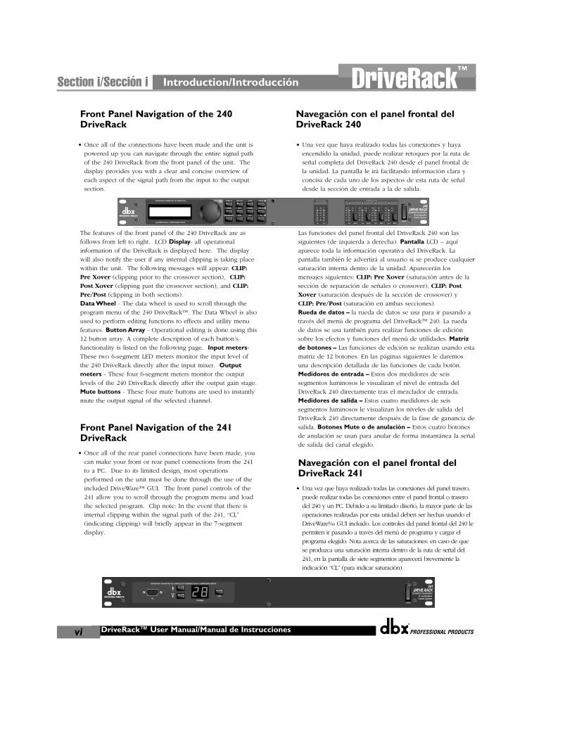
Front Panel Navigation of the 241DriveRack
• Once all of the rear panel connections have been made, you
can make your front or rear panel connections from the 241
to a PC. Due to its limited design, most operations
performed on the unit must be done through the use of the
included DriveWare™ GUI. The front panel controls of the
241 allow you to scroll through the program menu and load
the selected program. Clip note: In the event that there is
internal clipping within the signal path of the 241, “CL”
(indicating clipping) will briefly appear in the 7-segment
display.
Navegación con el panel frontal delDriveRack 240
• Una vez que haya realizado todas las conexiones y haya
encendido la unidad, puede realizar retoques por la ruta de
señal completa del DriveRack 240 desde el panel frontal de
la unidad. La pantalla le irá facilitando información clara y
concisa de cada uno de los aspectos de esta ruta de señal
desde la sección de entrada a la de salida.
Las funciones del panel frontal del DriveRack 240 son las
siguientes (de izquierda a derecha). Pantalla LCD – aquí
aparece toda la información operativa del DriveRack. La
pantalla también le advertirá al usuario si se produce cualquiersaturación interna dentro de la unidad. Aparecerán los
mensajes siguientes: CLIP: Pre Xover (saturación antes de la
sección de separación de señales o crossover), CLIP: Post
Xover (saturación después de la sección de crossover) y
CLIP: Pre/Post (saturación en ambas secciones).
Rueda de datos – la rueda de datos se usa para ir pasando a
través del menú de programa del DriveRack™ 240. La rueda
de datos se usa también para realizar funciones de edición
sobre los efectos y funciones del menú de utilidades. Matrizde botones – Las funciones de edición se realizan usando esta
matriz de 12 botones. En las páginas siguientes le daremos
una descripción detallada de las funciones de cada botón.
Medidores de entrada – Estos dos medidores de seis
segmentos luminosos le visualizan el nivel de entrada del
DriveRack 240 directamente tras el mezclador de entrada.
Medidores de salida – Estos cuatro medidores de seis
segmentos luminosos le visualizan los niveles de salida del
DriveRack 240 directamente después de la fase de ganancia de
salida. Botones Mute o de anulación – Estos cuatro botones
de anulación se usan para anular de forma instantánea la señal
de salida del canal elegido.
Navegación con el panel frontal delDriveRack 241
• Una vez que haya realizado todas las conexiones del panel trasero,
puede realizar todas las conexiones entre el panel frontal o trasero
del 240 y un PC. Debido a su limitado diseño, la mayor parte de las
operaciones realizadas por esta unidad deben ser hechas usando el
DriveWare‰ GUI incluido. Los controles del panel frontal del 240 le
permiten ir pasando a través del menú de programa y cargar el
programa elegido. Nota acerca de las saturaciones: en caso de que
se produzca una saturación interna dentro de la ruta de señal del
241, en la pantalla de siete segmentos aparecerá brevemente la
indicación “CL” (para indicar saturación).

®
Getting Started/InicioSection 1/Sección 1DriveRack™
Getting Started/Inicio
®
DriveRack™ User Manual/Manual de Instrucciones2
Section 1/Sección 1 DriveRack™
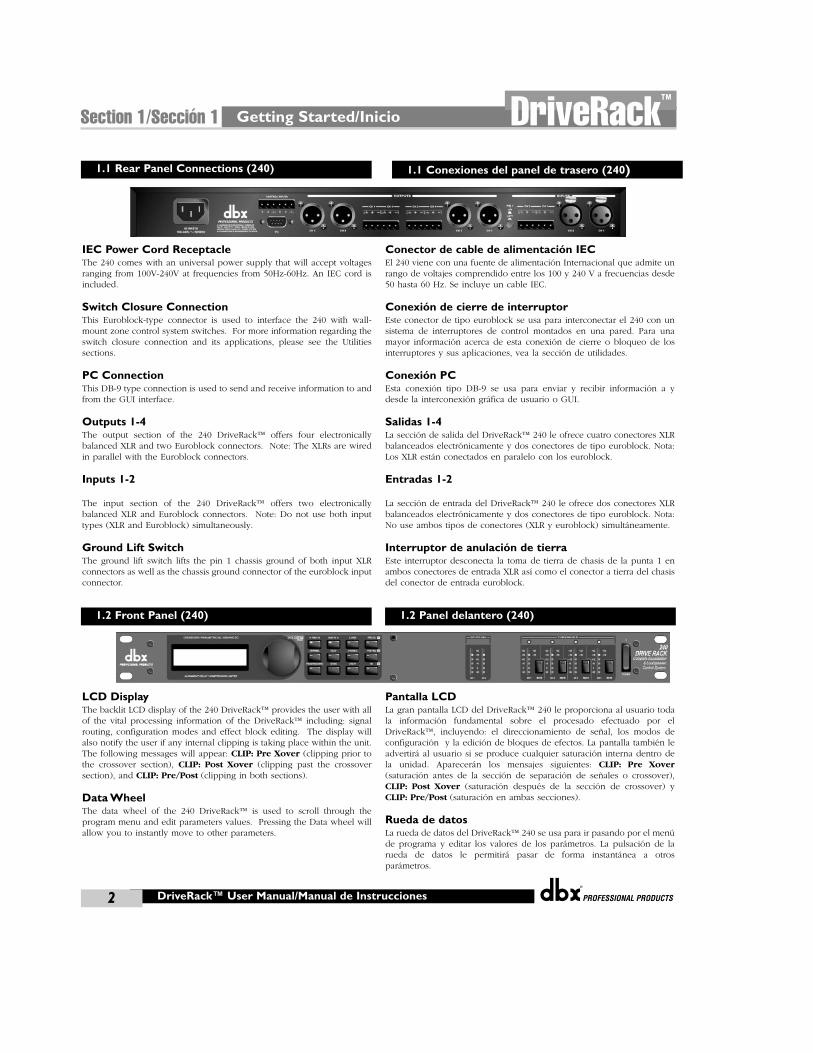
IEC Power Cord ReceptacleThe 240 comes with an universal power supply that will accept voltagesranging from 100V-240V at frequencies from 50Hz-60Hz. An IEC cord isincluded.
Switch Closure ConnectionThis Euroblock-type connector is used to interface the 240 with wall-mount zone control system switches. For more information regarding theswitch closure connection and its applications, please see the Utilitiessections.
PC ConnectionThis DB-9 type connection is used to send and receive information to andfrom the GUI interface.
Outputs 1-4The output section of the 240 DriveRack™ offers four electronicallybalanced XLR and two Euroblock connectors. Note: The XLRs are wiredin parallel with the Euroblock connectors.
Inputs 1-2
The input section of the 240 DriveRack™ offers two electronicallybalanced XLR and Euroblock connectors. Note: Do not use both inputtypes (XLR and Euroblock) simultaneously.
Ground Lift SwitchThe ground lift switch lifts the pin 1 chassis ground of both input XLRconnectors as well as the chassis ground connector of the euroblock inputconnector.
LCD DisplayThe backlit LCD display of the 240 DriveRack™ provides the user with allof the vital processing information of the DriveRack™ including: signalrouting, configuration modes and effect block editing. The display willalso notify the user if any internal clipping is taking place within the unit.The following messages will appear: CLIP: Pre Xover (clipping prior tothe crossover section), CLIP: Post Xover (clipping past the crossoversection), and CLIP: Pre/Post (clipping in both sections).
Data WheelThe data wheel of the 240 DriveRack™ is used to scroll through theprogram menu and edit parameters values. Pressing the Data wheel willallow you to instantly move to other parameters.
Conector de cable de alimentación IECEl 240 viene con una fuente de alimentación Internacional que admite unrango de voltajes comprendido entre los 100 y 240 V a frecuencias desde50 hasta 60 Hz. Se incluye un cable IEC.
Conexión de cierre de interruptorEste conector de tipo euroblock se usa para interconectar el 240 con unsistema de interruptores de control montados en una pared. Para unamayor información acerca de esta conexión de cierre o bloqueo de losinterruptores y sus aplicaciones, vea la sección de utilidades.
Conexión PCEsta conexión tipo DB-9 se usa para enviar y recibir información a ydesde la interconexión gráfica de usuario o GUI.
Salidas 1-4La sección de salida del DriveRack™ 240 le ofrece cuatro conectores XLRbalanceados electrónicamente y dos conectores de tipo euroblock. Nota:Los XLR están conectados en paralelo con los euroblock.
Entradas 1-2
La sección de entrada del DriveRack™ 240 le ofrece dos conectores XLRbalanceados electrónicamente y dos conectores de tipo euroblock. Nota:No use ambos tipos de conectores (XLR y euroblock) simultáneamente.
Interruptor de anulación de tierraEste interruptor desconecta la toma de tierra de chasis de la punta 1 enambos conectores de entrada XLR así como el conector a tierra del chasisdel conector de entrada euroblock.
Pantalla LCDLa gran pantalla LCD del DriveRack™ 240 le proporciona al usuario todala información fundamental sobre el procesado efectuado por elDriveRack™, incluyendo: el direccionamiento de señal, los modos deconfiguración y la edición de bloques de efectos. La pantalla también leadvertirá al usuario si se produce cualquier saturación interna dentro dela unidad. Aparecerán los mensajes siguientes: CLIP: Pre Xover(saturación antes de la sección de separación de señales o crossover),CLIP: Post Xover (saturación después de la sección de crossover) yCLIP: Pre/Post (saturación en ambas secciones).
Rueda de datosLa rueda de datos del DriveRack™ 240 se usa para ir pasando por el menúde programa y editar los valores de los parámetros. La pulsación de larueda de datos le permitirá pasar de forma instantánea a otrosparámetros.
1.1 Rear Panel Connections (240)
1.2 Front Panel (240)
1.1 Conexiones del panel de trasero (240)
1.2 Panel delantero (240)
®
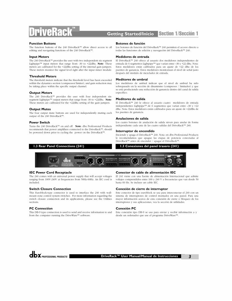
Function ButtonsThe function buttons of the 240 DriveRack™ allow direct access to allediting and navigating functions of the 240 DriveRack™.
Input MetersThe 240 DriveRack™ provides the user with two independent six segmentLightpipe™ input meters that range from -30 to +22dBu. Note: Thesemeters are calibrated for the +22dBu setting of the internal gain jumpers.These meters monitor the signal level right after the input mixer module.
Threshold MetersThe threshold meters indicate that the threshold level has been exceededwithin the dynamics section (compressor/limiter), and gain reduction maybe taking place within the specific output channel.
Output MetersThe 240 DriveRack™ provides the user with four independent six-segment Lightpipe™ output meters that range from -30 to +22dBu. Note:These meters are calibrated for the +22dBu setting of the gain jumpers.
Output MutesThe four output mute buttons are used for independently muting eachoutput of the 240 DriveRack™.
Power SwitchTurns the 240 DriveRack™ on and off. Note: dbx Professional Productsrecommends that power amplifiers connected to the DriveRack™, shouldbe powered down prior to cycling the power on the DriveRack™.
IEC Power Cord ReceptacleThe 240 comes with an universal power supply that will accept voltagesranging from 100V-240V at frequencies from 50Hz-60Hz. An IEC cord isincluded.
Switch Closure ConnectionThis Euroblock-type connector is used to interface the 240 with wall-mount zone control system switches. For more information regarding theswitch closure connection and its applications, please see the Utilitiessections.
PC ConnectionThis DB-9 type connection is used to send and receive information to andfrom the computer running the DriveWare™ software.
Botones de funciónLos botones de función del DriveRack™ 240 permiten el acceso directo atodas las funciones de edición y navegación del DriveRack™ 240.
Medidores de entradaEl DriveRack™ 240 ofrece al usuario dos medidores independientes deentrada de 6 segmentos Lightpipe™ que varían entre –30 y +22 dBu. Nota:Estos medidores están calibrados para un ajuste de +22 dBu de lospuentes de ganancia. Estos medidores monitorizan el nivel de señal justodespués del módulo de mezclador de entrada.
Meditores de umbralLos medidores de umbral indican que el nivel de umbral ha sidosobrepasado en la sección de dinamismo (compresor / limitador) y quese está produciendo una reducción de ganancia dentro del canal de salidaespecífico.
Meditores de salidaEl DriveRack™ 240 le ofrece al usuario cuatro medidores de entradaindependientes Lightpipe™ de 6 segmentos que varían entre –30 y +22dBu. Nota: Estos medidores están calibrados para un ajuste de +22dBu delos puentes de ganancia.
Anulaciones de salidaLos cuatro botones de anulación de salida sirven para anular de formaindependiente cada una de las cuatro salidas del DriveRack™ 240.
Interruptor de encendidoEnciende y apaga el DriveRack™ 240. Nota: en dbx Professional Productsle recomendamos que apague las etapas de potencia conectadas alDriveRack™ antes de encender / apagar el DriveRack™.
Conector de cable de alimentación IECEl 241 viene con una fuente de alimentación Internacional que admitevoltajes comprendidos entre 100 y 240 V a frecuencias que van desde 50hasta 60 Hz. Se incluye un cable IEC.
Conexión de cierre de interruptorEste conector de tipo euroblock se usa para interconectar el 240 con unsistema de interruptores de control montados en una pared. Para unamayor información acerca de esta conexión de cierre o bloqueo de losinterruptores y sus aplicaciones, vea la sección de utilidades.
Conexión PCEsta conexión tipo DB-9 se usa para enviar y recibir información a ydesde un ordenador que use el programa DriveWare™.
Getting Started/Inicio Section 1/Sección 1DriveRack™
DriveRack™ User Manual/Manual de Instrucciones 3
1.3 Rear Panel Connections (241) 1.3 Conexiones del panel trasero (241)
®
DriveRack™ User Manual/Manual de Instrucciones4
Section 1/Sección 1
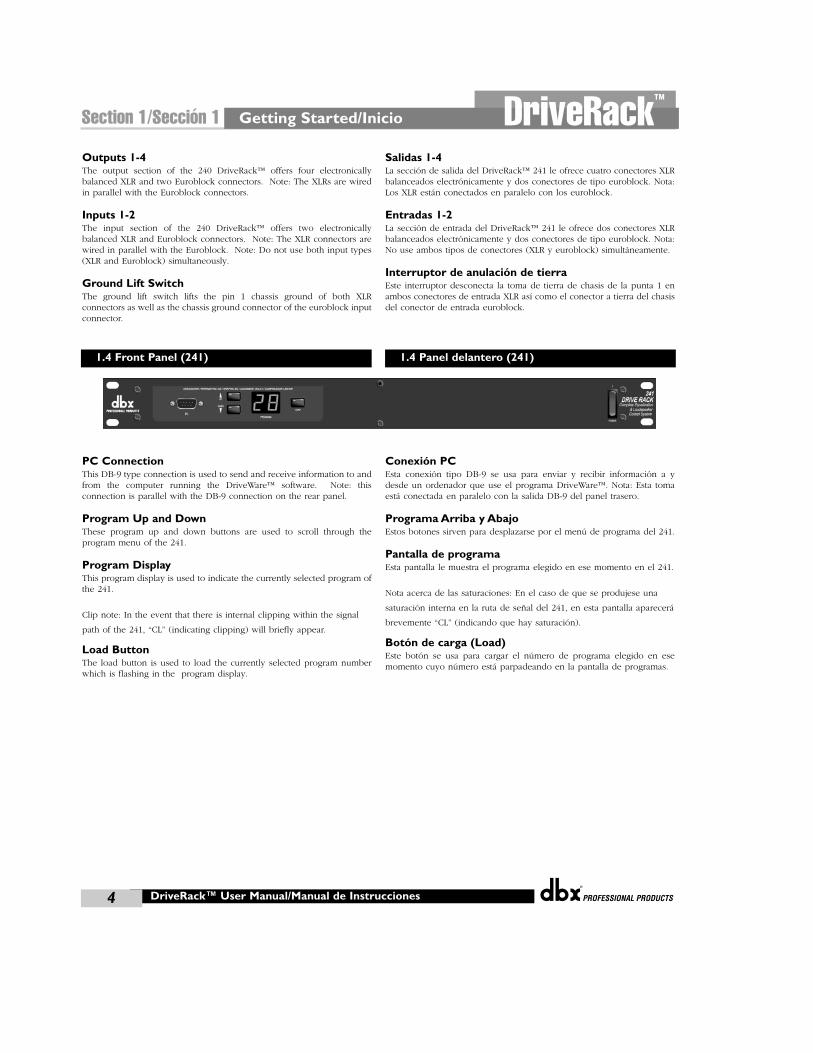
Outputs 1-4The output section of the 240 DriveRack™ offers four electronicallybalanced XLR and two Euroblock connectors. Note: The XLRs are wiredin parallel with the Euroblock connectors.
Inputs 1-2The input section of the 240 DriveRack™ offers two electronicallybalanced XLR and Euroblock connectors. Note: The XLR connectors arewired in parallel with the Euroblock. Note: Do not use both input types(XLR and Euroblock) simultaneously.
Ground Lift SwitchThe ground lift switch lifts the pin 1 chassis ground of both XLRconnectors as well as the chassis ground connector of the euroblock inputconnector.
PC ConnectionThis DB-9 type connection is used to send and receive information to andfrom the computer running the DriveWare™ software. Note: thisconnection is parallel with the DB-9 connection on the rear panel.
Program Up and DownThese program up and down buttons are used to scroll through theprogram menu of the 241.
Program DisplayThis program display is used to indicate the currently selected program ofthe 241.
Clip note: In the event that there is internal clipping within the signal
path of the 241, “CL” (indicating clipping) will briefly appear.
Load ButtonThe load button is used to load the currently selected program numberwhich is flashing in the program display.
Salidas 1-4La sección de salida del DriveRack™ 241 le ofrece cuatro conectores XLRbalanceados electrónicamente y dos conectores de tipo euroblock. Nota:Los XLR están conectados en paralelo con los euroblock.
Entradas 1-2La sección de entrada del DriveRack™ 241 le ofrece dos conectores XLRbalanceados electrónicamente y dos conectores de tipo euroblock. Nota:No use ambos tipos de conectores (XLR y euroblock) simultáneamente.
Interruptor de anulación de tierraEste interruptor desconecta la toma de tierra de chasis de la punta 1 enambos conectores de entrada XLR así como el conector a tierra del chasisdel conector de entrada euroblock.
Conexión PCEsta conexión tipo DB-9 se usa para enviar y recibir información a ydesde un ordenador que use el programa DriveWare™. Nota: Esta tomaestá conectada en paralelo con la salida DB-9 del panel trasero.
Programa Arriba y AbajoEstos botones sirven para desplazarse por el menú de programa del 241.
Pantalla de programaEsta pantalla le muestra el programa elegido en ese momento en el 241.
Nota acerca de las saturaciones: En el caso de que se produjese una
saturación interna en la ruta de señal del 241, en esta pantalla aparecerá
brevemente “CL” (indicando que hay saturación).
Botón de carga (Load)Este botón se usa para cargar el número de programa elegido en esemomento cuyo número está parpadeando en la pantalla de programas.
Getting Started/Inicio DriveRack™
1.4 Front Panel (241) 1.4 Panel delantero (241)

EDITINGFUNCTIONS
FUNCIONES DE EDICIÓN
®
Editing Functions/Funciones de edición
Section 2/Sección 2DriveRack™
Editing Functions/Funciones de Edición
®
6
Section 2/Sección 2 DriveRack™
The 240 DriveRack™ has been carefully designed and engineered toensure that all aspects of operation are intuitive and logical. Simplystated, the 240 DriveRack™ operating system was designed with user’sbest interest in mind. Editing the 240 DriveRack™ can be done byutilizing key functions and tools. This section will provide you withdetailed information on all of the tools used to optimize the editingperformance of your 240 DriveRack™ via the front panel.
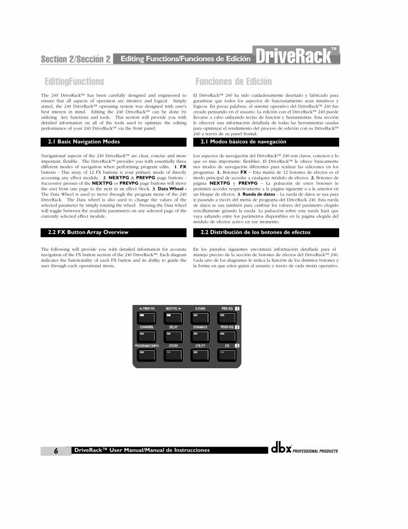
Navigational aspects of the 240 DriveRack™ are clear, concise and moreimportant: flexible. The DriveRack™ provides you with essentially threedifferent modes of navigation when performing program edits. 1. FXbuttons - This array of 12 FX buttons is your primary mode of directlyaccessing any effect module. 2. NEXTPG & PREVPG page buttons -Successive presses of the NEXTPG or PREVPG page buttons will movethe user from one page to the next in an effect block. 3. Data Wheel -The Data Wheel is used to move through the program menu of the 240DriveRack. The Data wheel is also used to change the values of theselected parameter by simply rotating the wheel. Pressing the Data wheelwill toggle between the available parameters on any selected page of thecurrently selected effect module.
The following will provide you with detailed information for accuratenavigation of the FX button section of the 240 DriveRack™. Each diagramindicates the functionality of each FX button and its ability to guide theuser through each operational menu.
El DriveRack™ 240 ha sido cuidadosamente diseñado y fabricado paragarantizar que todos los aspectos de funcionamiento sean intuitivos ylógicos. En pocas palabras, el sistema operativo del DriveRack™ 240 fuecreado pensando en el usuario. La edición con el DriveRack™ 240 puedellevarse a cabo utilizando teclas de función y herramientas. Esta secciónle ofrecerá una información detallada de todas las herramientas usadaspara optimizar el rendimiento del proceso de edición con su DriveRack™240 a través de su panel frontal.
Los aspectos de navegación del DriveRack™ 240 son claros, concisos y loque es más importante: flexibles. El DriveRack™ le ofrece básicamentetres modos de navegación diferentes para realizar las ediciones en losprogramas. 1. Botones FX – Esta matriz de 12 botones de efectos es elmodo principal de acceder a cualquier módulo de efectos. 2. Botones depágina NEXTPG y PREVPG – La pulsación de estos botones lepermitirá acceder respectivamente a la página siguiente o a la anterior enun bloque de efectos. 3. Rueda de datos – La rueda de datos se usa parair pasando a través del menú de programa del DriveRack 240. Esta ruedade datos se usa también para cambiar los valores del parámetro elegidosencillamente girando la rueda. La pulsación sobre esta rueda hará quevaya saltando entre los parámetros disponibles en la página elegida delmódulo de efectos activo en ese momento.
En los párrafos siguientes encontrará información detallada para elmanejo preciso de la sección de botones de efectos del DriveRack™ 240.Cada uno de los diagramas le indica la función de los distintos botones yla forma en que estos guían al usuario a través de cada menú operativo.
EditingFunctions
DriveRack™ User Manual/Manual de Instrucciones
2.1 Basic Navigation Modes
2.2 FX Button Array Overview
Funciones de Edición
2.1 Modos básicos de navegación
2.2 Distribución de los botones de efectos
®
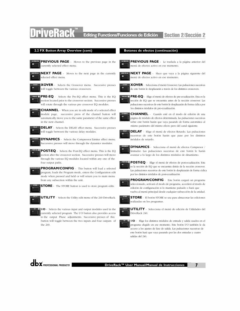
PREVIOUS PAGE - Moves to the previous page in the
currently selected effect menu.
NEXT PAGE - Moves to the next page in the currently
selected effect menu.
XOVER - Selects the Crossover menu. Successive presses
will toggle between the various crossovers.
PRE-EQ - Selects the Pre-EQ effect menu. This is the EQ
section located prior to the crossover section. Successive presses
will rotate through the various pre crossover EQ modules.
CHANNEL - When you are in edit mode of a selected effect
module page, successive press of the channel button will
automatically move you to the same parameter of the same effect
in the next channel.
DELAY - Selects the DELAY effect menu. Successive presses
will toggle between the various delay modules.
DYNAMICS - Selects the Compressor/Limiter effect menu.
Successive presses will move through the dynamics modules.
POST-EQ - Selects the Post-EQ effect menu. This is the EQ
section after the crossover section. Successive presses will move
through the various EQ modules located within any one of the
four output paths.
PROGRAM/CONFIG - This button will load a selected
program, loads the Program mode, enters the Configuration edit
mode when pressed and held or will return you to main menu
from any subsection within the unit.
STORE - The STORE button is used to store program edits.
UTILITY - Selects the Utility edit menu of the 240 DriveRack.
1/O - Selects the various input and output modules used in the
currently selected program The I/O button also provides access
to the output Phase adjustments. Successive presses of this
button will toggle between the two inputs and four outputs of
the 240.
PREVIOUS PAGE - Le traslada a la página anterior del
menú de efectos activo en ese momento.
NEXT PAGE - Hace que vaya a la página siguiente del
menú de efectos activo en ese momento.
XOVER - Selecciona el menú Crossover. Las pulsaciones sucesivas
de este botón le desplazarán a través de los distintos crossovers.
PRE-EQ - Elige el menú de efectos de pre-ecualización. Esta es la
sección de EQ que se encuentra antes de la sección crossover. Las
pulsaciones sucesivas de este botón le desplazarán de forma cíclica por
los distintos módulos de pre-ecualización.
CHANNEL - Cuando esté en el modo de edición de una
página de módulo de efectos determinada, las pulsaciones sucesivas
sobre este botón harán que vaya pasando de forma automática al
mismo parámetro del mismo efecto pero del canal siguiente.
DELAY - Elige el menú de efectos Retardo. Las pulsaciones
sucesivas de este botón harán que pase por los distintos
módulos de retardo.
DYNAMICS - Selecciona el menú de efectos Compresor /
limitador. Las pulsaciones sucesivas de este botón le harán
avanzar a lo largo de los distintos módulos de dinamismo.
POST-EQ - Elige el menú de efectos de post-ecualización. Esta
es la sección de EQ que se encuentra detrás de la sección crossover.
Las pulsaciones sucesivas de este botón le desplazarán de forma cíclica
por los distintos módulos de post-ecualización
PROGRAM/CONFIG - Este botón cargará un programa
seleccionado, activará el modo de programa, accederá al modo de
edición de configuración si lo mantiene pulsado o hará que
vuelva al menú principal desde cualquier subsección de la unidad.
STORE - El botón STORE se usa para almacenar las ediciones
realizadas en los programas.
UTILITY - Selecciona el menú de edición de Utilidades del
DriveRack 240.
1/O - Elige los distintos módulos de entrada y salida usados en el
programa elegido en ese momento. Este botón I/O también le da
acceso a los ajustes de fase de salida. Las pulsaciones sucesivas de
este botón hará que vaya pasando por las dos entradas y cuatro
salidas del 240.
Editing Functions/Funciones de Edición Section 2/Sección 2DriveRack™
7DriveRack™ User Manual/Manual de Instrucciones
2.2 FX Button Array Overview (cont) Botones de efectos (continuación)
Editing Functions/Funciones de Edición
®
8
Section 2/Sección 2 DriveRack™
DriveRack™ User Manual/Manual de Instrucciones
2.3 Navigating the Pre-crossover EQ Section
2.4 Navigating the Post-crossover EQ Section
2.3 Navegación por las secciones del ecualizador
The EQ button toggles through
the EQs used in each channel of
the selected program
menu.
PEQ
GEQ
or
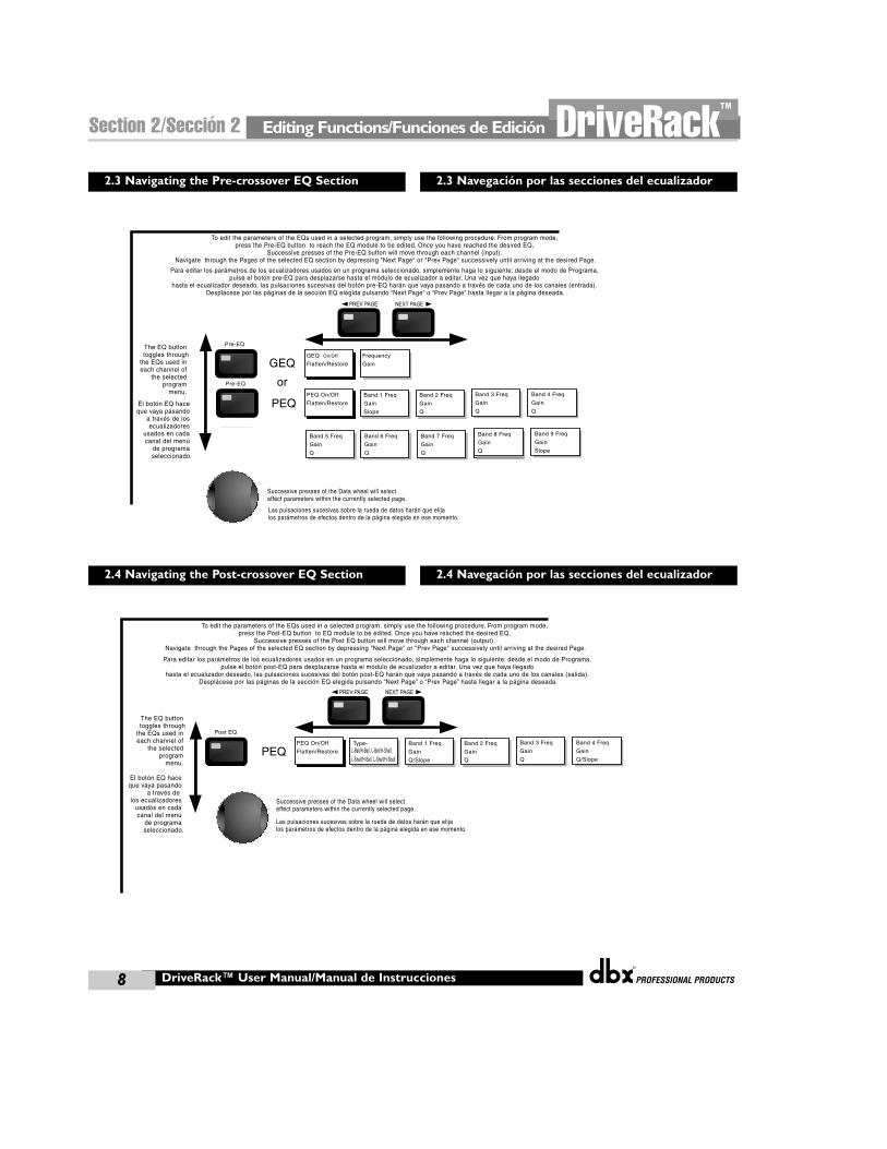
To edit the parameters of the EQs used in a selected program, simply use the following procedure. From program mode, press the Pre-EQ button to reach the EQ module to be edited. Once you have reached the desired EQ,
Successive presses of the Pre-EQ button will move through each channel (input). Navigate through the Pages of the selected EQ section by depressing "Next Page" or "Prev Page" successively until arriving at the desired Page.
GEQ On/Off
Flatten/Restore
Pre-EQ
Pre-EQ
Frequency
Gain
PEQ On/Off
Flatten/Restore
Band 1 Freq
Gain
Slope
Band 2 Freq
Gain
Q
Band 3 Freq
Gain
Q
Band 4 Freq
Gain
Q
Band 5 Freq
Gain
Q
Band 6 Freq
Gain
Q
Band 7 Freq
Gain
Q
Band 9 Freq
Slope
Level
Band 8 Freq
Gain
Q
Band 9 Freq
Gain
Slope
Successive presses of the Data wheel will select effect parameters within the currently selected page.
Para editar los parámetros de los ecualizadores usados en un programa seleccionado, simplemente haga lo siguiente: desde el modo de Programa, pulse el botón pre-EQ para desplazarse hasta el módulo de ecualizador a editar. Una vez que haya llegado
hasta el ecualizador deseado, las pulsaciones sucesivas del botón pre-EQ harán que vaya pasando a través de cada uno de los canales (entrada). Desplácese por las páginas de la sección EQ elegida pulsando “Next Page” o “Prev Page” hasta llegar a la página deseada.
El botón EQ hace que vaya pasando
a través de los ecualizadores
usados en cada canal del menú
de programa seleccionado.
Las pulsaciones sucesivas sobre la rueda de datos harán que elija los parámetros de efectos dentro de la página elegida en ese momento.
2.4 Navegación por las secciones del ecualizador
The EQ button toggles through
the EQs used in each channel of
the selected program
menu.
PEQ
To edit the parameters of the EQs used in a selected program, simply use the following procedure. From program mode, press the Post-EQ button to EQ module to be edited. Once you have reached the desired EQ,
Successive presses of the Post EQ button will move through each channel (output). Navigate through the Pages of the selected EQ section by depressing "Next Page" or "Prev Page" successively until arriving at the desired Page.
Post EQ
PEQ On/Off
Flatten/Restore
Band 1 Freq
Gain
Q/Slope
Type- L-Bell/H-Bell, L-Bell/H-Shelf, L-Shelf/H-Bell, L-Shelf/H-Shelf,
Band 2 Freq
Gain
Q
Band 3 Freq
Gain
Q
Band 4 Freq
Gain
Q/Slope
Successive presses of the Data wheel will select effect parameters within the currently selected page.
Para editar los parámetros de los ecualizadores usados en un programa seleccionado, simplemente haga lo siguiente: desde el modo de Programa, pulse el botón post-EQ para desplazarse hasta el módulo de ecualizador a editar. Una vez que haya llegado
hasta el ecualizador deseado, las pulsaciones sucesivas del botón post-EQ harán que vaya pasando a través de cada uno de los canales (salida). Desplácese por las páginas de la sección EQ elegida pulsando “Next Page” o “Prev Page” hasta llegar a la página deseada.
El botón EQ hace que vaya pasando
a través delos ecualizadores
usados en cada canal del menú
de programa seleccionado.
Las pulsaciones sucesivas sobre la rueda de datos harán que elija los parámetros de efectos dentro de la página elegida en ese momento.
®
Editing Functions/Funciones de Edición Section 2/Sección 2DriveRack™
9DriveRack™ User Manual/Manual de Instrucciones
2.5 Navigating the XOVER Sections
2.6 Navigating the Delay Section
2.5 Navegación por las secciones X-OVER
2.6 Navegación por la sección de retardo
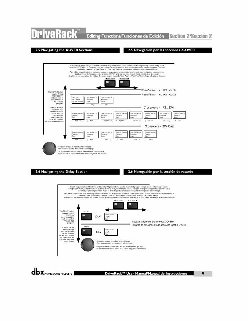
The X-OVER button toggles through the Crossover
modules used in each channel of
the selected program.
Crossovers - 1X2...2X4
Type (BS,BW,L-R)FrequencySlope
High
To edit the parameters of the Crossover used in a selected program, simply use the following procedure. From program mode, press the X-OVER button. Once you have reached the Crossover module, Navigate through the Pages of the selected Crossover
module by pressing the "Next Page" or "Prev Page" buttons successively until arriving at the desired Page.
Type (BS,BW,L-R)FrequencySlope
High
Type (BS,BW,L-R)FrequencySlope
High Mid
Type (BS,BW,L-R)FrequencySlope
High Mid
Type (BS,BW,L-R)FrequencySlope
Low Mid
Type (BS,BW,L-R)FrequencySlope
Low Mid
Type (BS,BW,L-R)FrequencySlope
Low
Type (BS,BW,L-R)FrequencySlope
Low
Crossovers - 2X4 Dual
Type (BS,BW,L-R)FrequencySlope
High
Type (BS,BW,L-R)FrequencySlope
High
Type (BS,BW,L-R)FrequencySlope
Sub
Type (BS,BW,L-R)FrequencySlope
Sub
Type (BS,BW,L-R)FrequencySlope
SSub
Type (BS,BW,L-R)FrequencySlope
S Sub
Wires/Cables - 1X1, 1X2,1X3,1X4
Filters/Filtros - 1X1, 1X2,1X3,1X4Filter Type:Wire, Low Pass,High Pass, Band Pass
Type (BS,BW,L-R)FrequencySlope
Type (BS,BW,L-R)FrequencySlope
Successive presses of the Data wheel will select effect parameters within the currently selected page.
Para editar los parámetros de crossover usados en un programa seleccionado, simplemente siga el siguiente procedimiento. Desde el modo de Programa, pulse el botón X-OVER. Una vez que haya llegado hasta el módulo de Crossover,
desplácese por las páginas del módulo Crossover elegido pulsando “Next Page” o “Prev Page” hasta llegar a la página deseada.
El botón X-OVER hace que vaya
pasando a travésde los módulos
de Crossover usados en cada
canal del menú de programa seleccionado.
Las pulsaciones sucesivas sobre la rueda de datos harán que elija los parámetros de efectos dentro de la página elegida en ese momento..
The DELAY button toggles through
the Delay modules used in each channel of
the selected program.
DLY
DLY
Speaker Alignment Delay (Post X-OVER)
To edit the parameters of the Delay and Speaker Alignment Delay used in a selected program, simply use the following procedure.From program mode, press the DELAY button to move to Delay module to be edited. Navigate through the Pages of the selected Delay
module by depressing the "Next Page" or "Prev Page" buttons successively until arriving at the desired Page.
Delay On/Off
Length
Type
DELAY
DELAY
Delay On/Off
Length
Type
Successive presses of the Data wheel will select effect parameters within the currently selected page.
Para editar los parámetros de Retardo y Retardo de alineación de altavoces usados en un programa seleccionado, simplemente haga lo siguiente: desde el modo de Programa, pulse el botón DELAY para desplazarse hasta el módulo de retardo a editar.
Muévase por las distintas páginas del módulo de retardo elegido pulsando los botones “Next Page” o “Prev Page” hasta llegar a la página deseada.
El botón DELAY hace que vaya
pasando a travésde los módulos
de Retardo usados en cada canal del
menú de programa seleccionado.
Las pulsaciones sucesivas sobre la rueda de datos harán que elija los parámetros de efectos dentro de la página elegida en ese momento.
Retardo de alineamiento de altavoces (post X-OVER)
Editing Functions/Funciones de Edición
®
10
Section 2/Sección 2 DriveRack™
DriveRack™ User Manual/Manual de Instrucciones
2.7 Navigating the Dynamics Section
2.8 Navigating the I/O Section
2.9 Navigating the Utility Section
2.7 Navegación por la sección de dinamismo
Navegación por la sección de Entrada y Salida
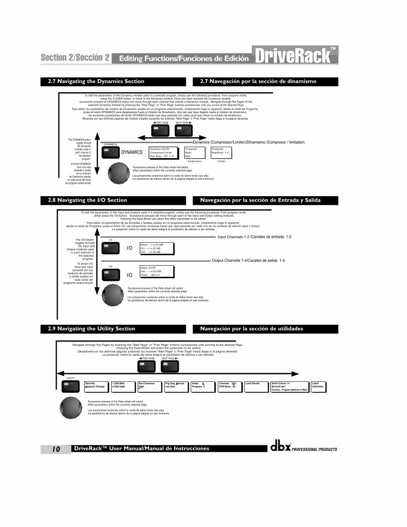
The DYNAMICS button toggles through the Dynamics
modules used in each channel of
the selected program.
DYNAMICSDynamics On/Off
Compressor/Limiter
Over Easy Off, 1-10
DYNAMICS
Compressor
Threshold
Ratio
Gain
Limiter
Threshold
PeakStop+ 1-6
Dynamics (Compressor/Limiter)/Dinamismo (Compresor / limitador)
To edit the parameters of the Dynamics module used in a selected program, simply use the following procedure. From program mode,press the X-OVER button to move to the Dynamics module. Once you have reached the Crossover module,
successive presses of DYNAMICS button will move through each channel that utilizes a Dynamics module. Navigate through the Pages of the selected Dynamics module by pressing the "Next Page" or "Prev Page" buttons successively until you arrive at the desired Page.
Successive presses of the Data wheel will select effect parameters within the currently selected page.
Para editar los parámetros del módulo de Dinamismo usados en un programa seleccionado, simplemente haga lo siguiente: desde el modo de Programa, pulse el botón DYNAMICS para desplazarse hasta el módulo de Dinamismo. Una vez que haya llegado hasta el módulo de dinamismo,
las sucesivas pulsaciones del botón DYNAMICS harán que vaya pasando por cada canal que utilice un módulo de dinamismo. Muévase por las distintas páginas del módulo elegido pulsando los botones “Next Page” o “Prev Page” hasta llegar a la página deseada.
El botón DYNAMICS hace que vaya
pasando a travésde los módulos
de Dinamismo usados en cada canal del menú
de programa seleccionado.
Las pulsaciones sucesivas sobre la rueda de datos harán que elija los parámetros de efectos dentro de la página elegida en ese momento.
The I/O button toggles through
the Input andOutput modules used
in each channel of the selected
program.
I/O
I/O
MGain - -∞ to 20.0dB
Ch1 - -∞ to 20.0dB
Ch2 - -∞ to 20.0dB
I/O
I/O Adjust On/Off
Gain - -∞ to 20.0dB
Phase - -360 to 0
Input Channels 1-2
Output Channels 1-4/Canales de salida 1-4
To edit the parameters of the Input and Ouptuts used in a selected program, simply use the following procedure. From program mode, either press the I/O button. Successive presses will move through each of the Input and Output editing modules.
Pressing the Data Wheel will select the effect parameter to be edited.
Successive presses of the Data wheel will select effect parameters within the currently selected page.
Para editar los parámetros de las Entradas y Salidas usados en un programa seleccionado, simplemente haga lo siguiente: desde el modo de Programa, pulse el botón I/O. Las pulsaciones sucesivas harán que vaya pasando por cada uno de los módulos de edición Input y Output.
La pulsación sobre la rueda de datos elegirá el parámetro de efectos a ser editado.
El botón I/O hace que vaya
pasando por los módulos de entrada y salida usados en
cada canal del programa seleccionado.
Las pulsaciones sucesivas sobre la rueda de datos harán que elija los parámetros de efectos dentro de la página elegida en ese momento.
/Canales de entrada 1-2
Navegación por la sección de utilidades
Navigate through the Pages by pressing the "Next Page" or "Prev Page" buttons successively until arriving at the desired Page. Pressing the Data Wheel will select the parameter to be edited.
LimiterSecurityProgram Change
Limiter1 Edit Med 2 Edit High
LimiterSet ClearanceHigh
LimiterPrg Chg NormalList Size
LimiterIndex 0Program 5
LimiterContrast 53%PUP Mute All
LimiterLatchDefinition
LimiterLoad Stored LimiterSwitch Closure 1-4Moment/LatchFunction - Program Up/Down or Mute
Successive presses of the Data wheel will select effect parameters within the currently selected page.
Desplácese por las distintas páginas pulsando los botones “Next Page” o “Prev Page” hasta llegar a la página deseada. La pulsación sobre la rueda de datos elegirá el parámetro de efectos a ser editado.
Las pulsaciones sucesivas sobre la rueda de datos harán que elija los parámetros de efectos dentro de la página elegida en ese momento.

CONFIGURATIONFUNCTIONS
FUNCIONES DECONFIGURACION
®
SOFTWARE/SOFTWARESection 3/Sección 3DriveRack™
Configuring the DriveRack™/Configuración del DriveRack™
®
12
Section 3/Sección 3 DriveRack™
DriveRack™ User Manual/Manual de Instrucciones
The Configuring section of the 240 and 241 DriveRack™ units will be yourkey to successful navigation of the configuration functions of theDriveRack™. The following information provides, descriptions aboutprogram functions and in depth configuration options of the 240 and 241DriveRack™ units.
The first step in understanding the thorough programming capabilities ofthe DriveRack™ is to understand the elements involved that combined,define a complete “program.” Within an individual program, there areseveral levels of editing that make up the complete program. Wheninitially entering a program, you will be at the “program” mode level.This level supplies the user with current program information such as:current signal path, effect usage, and program name. From this point, the240 or 241 DriveRack™ units give you the option of entering subsequentlevels of operation that are dedicated to program editing. These levelsinclude Configuration mode and Effect Edit mode. The key element toremember is that all of these components combined, make up theconventional “program”, and that they are all unique to each individualprogram. The Utility menu mode is accessed via the utility menu, and isnot part of a single program.
From the factory, the 240 and 241 DriveRack™ units are shipped with 20factory programs that utilize carefully constructed routing configurationsthat have been designed to accommodate virtually any soundreinforcement and installation application. The factory programs offer aclear an concise explanatory title to help you up and running in a timelymanner. These programs can also be used as templates or starting pointsfor the user to create custom programs.
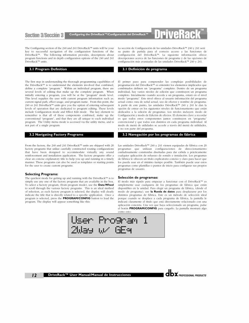
Selecting Programs:The quickest mode for getting up and running with the DriveRack™ is tosimply use any one of the factory programs that are available in the box.To select a factory program, (from program mode), use the Data Wheelto scroll through the various factory programs. This is an ideal methodof selection, as each factory program is selected, the display will clearlyindicate the title that is directly related to a specific application. Once aprogram is selected, press the PROGRAM/CONFIG button to load theprogram. The display will appear something like this:
La sección de Configuración de las unidades DriveRack™ 240 y 241 serásu punto de partida para el correcto acceso a las funciones deconfiguración del DriveRack™. La siguiente información ofrecedescripciones acerca de las funciones de programa y de las opciones deconfiguración más avanzadas de las unidades DriveRack™ 240 y 241.
El primer paso para comprender las complejas posibilidades deprogramación del DriveRack™ es entender los elementos implicados quecombinados definen un “programa” completo. Dentro de un programaindividual, hay varios niveles de edición que constituyen un programacompleto. Inicialmente cuando acceda a un programa, estará en el nivelmodo “programa”. Este nivel ofrece al usuario información del programaactual como: ruta de señal actual, uso de efectos y nombre de programa.A partir de este punto, las unidades DriveRack™ 240 y 241 le dan laopción de entrar en los siguientes niveles de funcionamiento que estándedicados a la edición de programas. Los niveles incluyen: modo deConfiguración y modo de Edición de efectos. El elemento clave a recordares que todos estos componentes juntos constituyen en “programa”convencional y que todos son distintos en cada programa individual. Almodo de menú de utilidades se accede a través del menú de utilidades,y no son parte del programa.
Las unidades DriveRack™ 240 y 241 vienen equipadas de fábrica con 20programas que utilizan configuraciones de direccionamientocuidadosamente construidas diseñadas para dar cabida a prácticamentecualquier aplicación de refuerzo de sonido e instalación. Los programasde fábrica le ofrecen un título explicatorio conciso y claro para hacer quelos pueda usar en el mínimo tiempo posible. También puede usar estosprogramas como plantillas o puntos de inicio para configurar sus propiosprogramas de usuario.
Selección de programas:El modo más rápido para empezar a funcionar con el DriveRack™ essimplemente usar cualquiera de los programas de fábrica que estándisponibles en la unidad. Para elegir un programa de fábrica, (desde elmodo de programa), use la Rueda de datos para desplazarse por losdistintos programas de fábrica. Este es un método de selección idealporque cuando se desplace a cada programa de fábrica, la pantalla leindicará claramente el título que está directamente relacionado con unaaplicación concreta. Una vez que haya seleccionado un programa, pulseel botón PROGRAM/CONFIG para cargarlo. La pantalla mostrará algocomo esto:
3.1 Program Definition
3.2 Navigating Factory Programs
3.1 Definición de programa
3.2 Navegación por los programas de fábrica
User Program 12Way w/ GEq
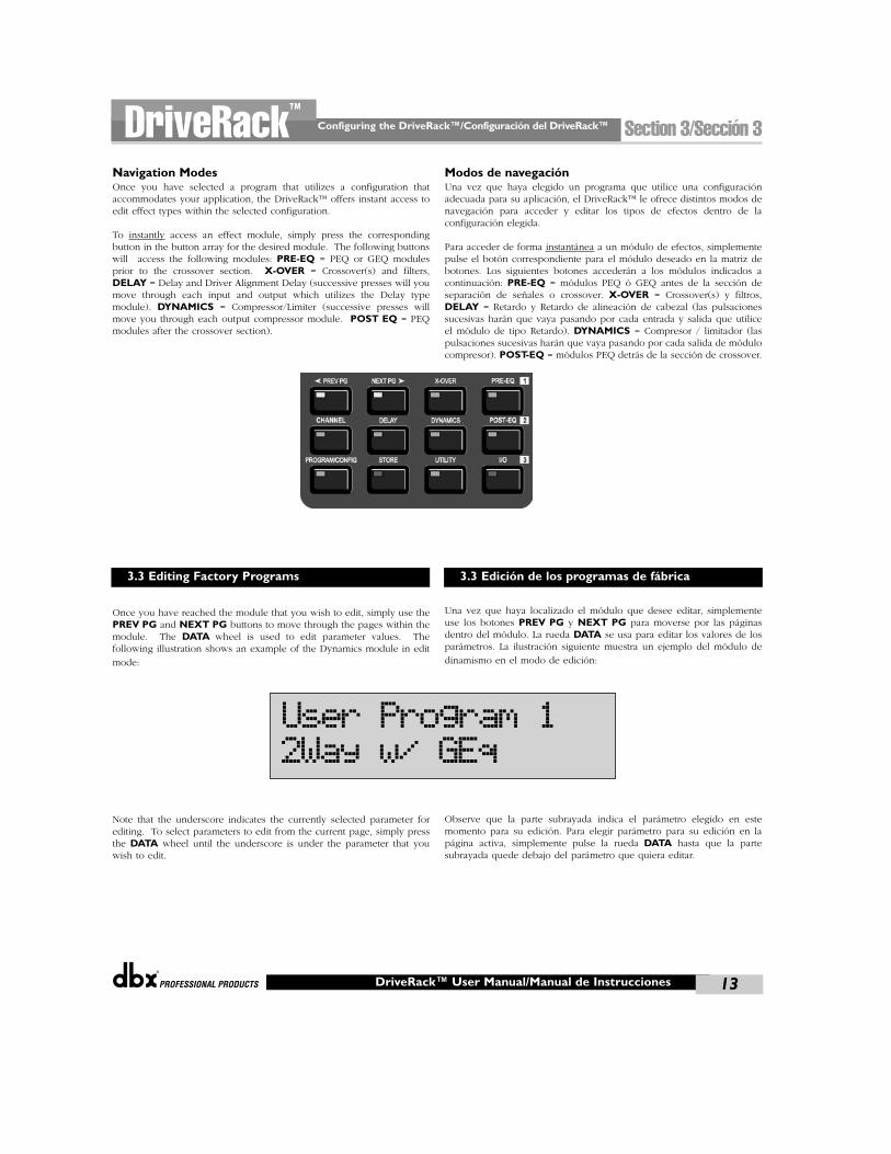
®
Configuring the DriveRack™/Configuración del DriveRack™ Section 3/Sección 3DriveRack™
13DriveRack™ User Manual/Manual de Instrucciones
Navigation ModesOnce you have selected a program that utilizes a configuration thataccommodates your application, the DriveRack™ offers instant access toedit effect types within the selected configuration.
To instantly access an effect module, simply press the correspondingbutton in the button array for the desired module. The following buttonswill access the following modules: PRE-EQ = PEQ or GEQ modulesprior to the crossover section. X-OVER = Crossover(s) and filters,DELAY = Delay and Driver Alignment Delay (successive presses will youmove through each input and output which utilizes the Delay typemodule). DYNAMICS = Compressor/Limiter (successive presses willmove you through each output compressor module. POST EQ = PEQmodules after the crossover section).
Once you have reached the module that you wish to edit, simply use the PREV PG and NEXT PG buttons to move through the pages within themodule. The DATA wheel is used to edit parameter values. Thefollowing illustration shows an example of the Dynamics module in edit
mode:
Note that the underscore indicates the currently selected parameter forediting. To select parameters to edit from the current page, simply pressthe DATA wheel until the underscore is under the parameter that youwish to edit.
Modos de navegaciónUna vez que haya elegido un programa que utilice una configuraciónadecuada para su aplicación, el DriveRack™ le ofrece distintos modos denavegación para acceder y editar los tipos de efectos dentro de laconfiguración elegida.
Para acceder de forma instantánea a un módulo de efectos, simplementepulse el botón correspondiente para el módulo deseado en la matriz debotones. Los siguientes botones accederán a los módulos indicados acontinuación: PRE-EQ = módulos PEQ ó GEQ antes de la sección deseparación de señales o crossover. X-OVER = Crossover(s) y filtros,DELAY = Retardo y Retardo de alineación de cabezal (las pulsacionessucesivas harán que vaya pasando por cada entrada y salida que utiliceel módulo de tipo Retardo). DYNAMICS = Compresor / limitador (laspulsaciones sucesivas harán que vaya pasando por cada salida de módulocompresor). POST-EQ = módulos PEQ detrás de la sección de crossover.
Una vez que haya localizado el módulo que desee editar, simplementeuse los botones PREV PG y NEXT PG para moverse por las páginasdentro del módulo. La rueda DATA se usa para editar los valores de losparámetros. La ilustración siguiente muestra un ejemplo del módulo de
dinamismo en el modo de edición:
Observe que la parte subrayada indica el parámetro elegido en estemomento para su edición. Para elegir parámetro para su edición en lapágina activa, simplemente pulse la rueda DATA hasta que la partesubrayada quede debajo del parámetro que quiera editar.
3.3 Editing Factory Programs 3.3 Edición de los programas de fábrica
User Program 12Way w/ GEq
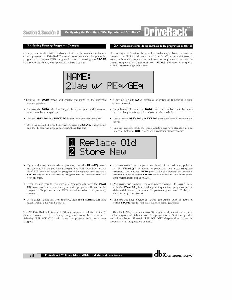
Configuring the DriveRack™/Configuración del DriveRack™
®
14
Section 3/Sección 3 DriveRack™
DriveRack™ User Manual/Manual de Instrucciones
Once you are satisfied with the changes that have been made to a factoryor user program, the DriveRack™ allows you to save these changes to theprogram as a custom USER program by simply pressing the STOREbutton and the display will appear something like this:
• Rotating the DATA wheel will change the icons on the currentlyselected position.
• Pressing the DATA wheel will toggle between upper and lowercaseletters, numbers or symbols.
• Use the PREV PG and NEXT PG button to move icon positions.
• Once the desired title has been written, press the STORE button againand the display will now appear something like this:
• If you wish to replace an existing program, press the 1/Pre-EQ buttonand the unit will ask you which program you wish to replace. Rotatethe DATA wheel to select the program to be replaced and press theSTORE button and the existing program will be replaced with thenew program.
• If you wish to store the program as a new program, press the 2/PostEQ button and the unit will ask you which program will precede theprogram. Simply rotate the DATA wheel to select the precedingprogram.
• Once either method has been selected, press the STORE button onceagain, and all edits will be saved.
The 240 DriveRack will store up to 50 user programs in addition to the 20factory programs. Note: Factory programs cannot be over-written.Selecting “REPLACE OLD” will move the program index to a userprogram.
Una vez que esté satisfecho con los cambios que haya realizado alprograma de fábrica o de usuario, el DriveRack™ le permitirá guardarestos cambios del programa en la forma de un programa personal deusuario simplemente pulsando el botón STORE, momento en el que lapantalla mostrará algo como esto:
• El giro de la rueda DATA cambiará los iconos de la posición elegidaen ese momento.
• La pulsación de la rueda DATA hará que cambie entre las letrasmayúsculas y minúsculas, los números o los símbolos.
• Use el botón PREV PG y NEXT PG para desplazar la posición delicono.
• Una vez que esté satisfecho con el nombre que haya elegido pulse denuevo el botón STORE y la pantalla mostrará algo como esto:
• Si desea reemplazar un programa de usuario ya existente, pulse elmando 1/Pre-EQ y la unidad le preguntará qué programa quieresustituir; Gire la rueda DATA para elegir el programa de usuario asustituir y pulse le botón STORE de nuevo, tras lo cual el programaserá reemplazado por el nuevo.
• Para guardar un programa como un nuevo programa de usuario, pulseel botón 2/Post EQ y la unidad le pedirá que elija el programa que irádelante del que va a almacenar. Simplemente gire la rueda DATA paraelegir el programa anterior.
• Una vez que haya elegido el método que quiera, pulse de nuevo elbotón STORE, tras lo cual sus ediciones serán guardadas.
El DriveRack 240 puede almacenar 50 programas de usuario además delos 20 programas de fábrica. Nota: Los programas de fábrica no puedenser sobregrabados. El elegir “REPLACE OLD” desplazará el índice delprograma a un programa de usuario.
3.4 Saving Factory Programs Changes 3.4 Almacenamiento de los cambios de los programas de fábrica
NAME:2Way w/ PEq/GEq
1 Replace Old2 Store New
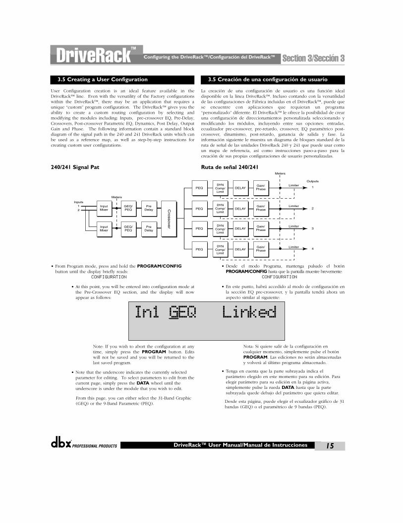
®
Configuring the DriveRack™/Configuración del DriveRack™ Section 3/Sección 3DriveRack™
15DriveRack™ User Manual/Manual de Instrucciones
User Configuration creation is an ideal feature available in theDriveRack™ line. Even with the versatility of the Factory configurationswithin the DriveRack™, there may be an application that requires aunique “custom” program configuration. The DriveRack™ gives you theability to create a custom routing configuration by selecting andmodifying the modules including: Inputs, pre-crossover EQ, Pre-Delay,Crossovers, Post-crossover Parametric EQ, Dynamics, Post Delay, OutputGain and Phase. The following information contain a standard blockdiagram of the signal path in the 240 and 241 DriveRack units which canbe used as a reference map, as well as step-by-step instructions forcreating custom user configurations.
240/241 Signal Pat
• From Program mode, press and hold the PROGRAM/CONFIGbutton until the display briefly reads:
CONFIGURATION
• At this point, you will be entered into configuration mode atthe Pre-Crossover EQ section, and the display will nowappear as follows:
Note: If you wish to abort the configuration at anytime, simply press the PROGRAM button. Editswill not be saved and you will be returned to thelast saved program.
• Note that the underscore indicates the currently selectedparameter for editing. To select parameters to edit from thecurrent page, simply press the DATA wheel until theunderscore is under the module that you wish to edit.
From this page, you can either select the 31-Band Graphic(GEQ) or the 9-Band Parametric (PEQ).
La creación de una configuración de usuario es una función idealdisponible en la línea DriveRack™. Incluso contando con la versatilidadde las configuraciones de Fábrica incluidas en el DriveRack™, puede quese encuentre con aplicaciones que requieran un programa“personalizado” diferente. El DriveRack™ le ofrece la posibilidad de crearuna configuración de direccionamientos personalizada seleccionando ymodificando los módulos, incluyendo entre sus opciones: entradas,ecualizador pre-crossover, pre-retardo, crossover, EQ paramétrico post-crossover, dinamismo, post-retardo, ganancia de salida y fase. Lainformación siguiente le muestra un diagrama de bloques standard de laruta de señal de las unidades DriveRack 240 y 241 que puede usar comoun mapa de referencia, así como instrucciones paso-a-paso para lacreación de sus propias configuraciones de usuario personalizadas.
Ruta de señal 240/241
• Desde el modo Programa, mantenga pulsado el botónPROGRAM/CONFIG hasta que la pantalla muestre brevemente:
CONFIGURATION
• En este punto, habrá accedido al modo de configuración enla sección EQ pre-crossover, y la pantalla tendrá ahora unaspecto similar al siguiente:
Nota: Si quiere salir de la configuración encualquier momento, simplemente pulse el botónPROGRAM. Las ediciones no serán almacenadasy volverá al último programa almacenado.
• Tenga en cuenta que la parte subrayada indica elparámetro elegido en este momento para su edición. Paraelegir parámetro para su edición en la página activa,simplemente pulse la rueda DATA hasta que la partesubrayada quede debajo del parámetro que quiera editar.
Desde esta página, puede elegir el ecualizador gráfico de 31bandas (GEQ) o el paramétrico de 9 bandas (PEQ).
3.5 Creating a User Configuration 3.5 Creación de una configuración de usuario
InputMixer
InputMixer
GEQ/PEQ
GEQ/PEQ
PreDelay
PreDelay
PEQ
Meters
Inputs12
Outputs
1
2
3
4
Gain/Phase
Gain/Phase
Gain/Phase
Gain/Phase
Cro
ssove
r
PEQ
PEQ
PEQ
DYNComp/Limit
DYNComp/Limit
DYNComp/Limit
DYNComp/Limit
DELAY
DELAY
DELAY
DELAY
Meters
Limiter
Limiter
Limiter
Limiter
In1 GEQ Linked
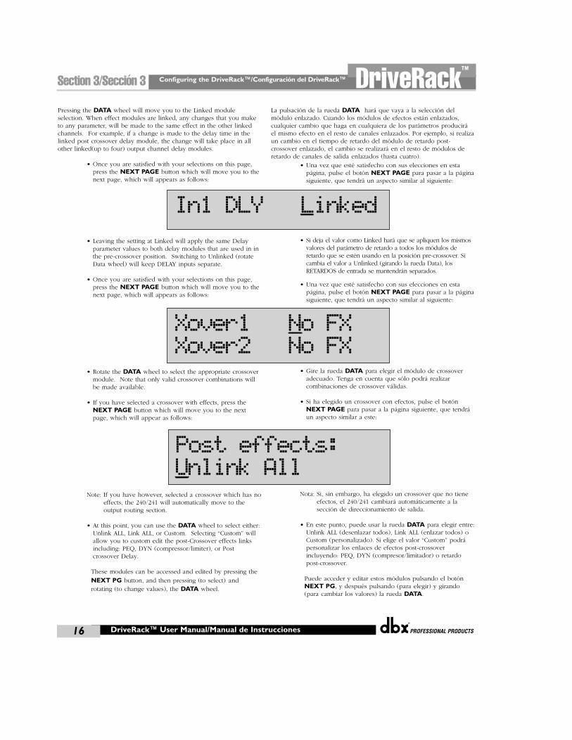
Configuring the DriveRack™/Configuración del DriveRack™
®
16
Section 3/Sección 3 DriveRack™
Pressing the DATA wheel will move you to the Linked moduleselection. When effect modules are linked, any changes that you maketo any parameter, will be made to the same effect in the other linkedchannels. For example, if a change is made to the delay time in thelinked post crossover delay module, the change will take place in allother linked(up to four) output channel delay modules.
• Once you are satisfied with your selections on this page,press the NEXT PAGE button which will move you to thenext page, which will appears as follows:
• Leaving the setting at Linked will apply the same Delayparameter values to both delay modules that are used in inthe pre-crossover position. Switching to Unlinked (rotateData wheel) will keep DELAY inputs separate.
• Once you are satisfied with your selections on this page,press the NEXT PAGE button which will move you to thenext page, which will appears as follows:
• Rotate the DATA wheel to select the appropriate crossovermodule. Note that only valid crossover combinations willbe made available.
• If you have selected a crossover with effects, press theNEXT PAGE button which will move you to the nextpage, which will appear as follows:
Note: If you have however, selected a crossover which has noeffects, the 240/241 will automatically move to theoutput routing section.
• At this point, you can use the DATA wheel to select either:Unlink ALL, Link ALL, or Custom. Selecting “Custom” willallow you to custom edit the post-Crossover effects linksincluding: PEQ, DYN (compressor/limiter), or Postcrossover Delay.
These modules can be accessed and edited by pressing the
NEXT PG button, and then pressing (to select) androtating (to change values), the DATA wheel.
La pulsación de la rueda DATA hará que vaya a la selección delmódulo enlazado. Cuando los módulos de efectos están enlazados,cualquier cambio que haga en cualquiera de los parámetros produciráel mismo efecto en el resto de canales enlazados. Por ejemplo, si realizaun cambio en el tiempo de retardo del módulo de retardo post-crossover enlazado, el cambio se realizará en el resto de módulos deretardo de canales de salida enlazados (hasta cuatro).
• Una vez que esté satisfecho con sus elecciones en estapágina, pulse el botón NEXT PAGE para pasar a la páginasiguiente, que tendrá un aspecto similar al siguiente:
• Si deja el valor como Linked hará que se apliquen los mismosvalores del parámetro de retardo a todos los módulos deretardo que se estén usando en la posición pre-crossover. Sicambia el valor a Unlinked (girando la rueda Data), losRETARDOS de entrada se mantendrán separados.
• Una vez que esté satisfecho con sus elecciones en estapágina, pulse el botón NEXT PAGE para pasar a la páginasiguiente, que tendrá un aspecto similar al siguiente:
• Gire la rueda DATA para elegir el módulo de crossoveradecuado. Tenga en cuenta que sólo podrá realizarcombinaciones de crossover válidas.
• Si ha elegido un crossover con efectos, pulse el botónNEXT PAGE para pasar a la página siguiente, que tendráun aspecto similar a este:
Nota: Si, sin embargo, ha elegido un crossover que no tieneefectos, el 240/241 cambiará automáticamente a lasección de direccionamiento de salida.
• En este punto, puede usar la rueda DATA para elegir entre:Unlink ALL (desenlazar todos), Link ALL (enlazar todos) oCustom (personalizado). Si elige el valor “Custom” podrápersonalizar los enlaces de efectos post-crossoverincluyendo: PEQ, DYN (compresor/limitador) o retardopost-crossover.
Puede acceder y editar estos módulos pulsando el botónNEXT PG, y después pulsando (para elegir) y girando(para cambiar los valores) la rueda DATA.
DriveRack™ User Manual/Manual de Instrucciones
In1 DLY Linked
Xover1 No FXXover2 No FX
Post effects:Unlink All
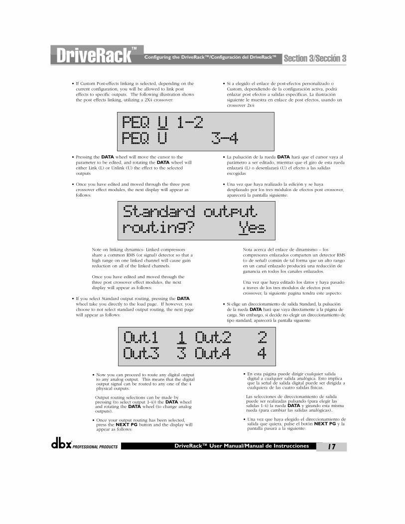
®
Configuring the DriveRack™/Configuración del DriveRack™ Section 3/Sección 3DriveRack™
17
• If Custom Post-effects linking is selected, depending on thecurrent configuration, you will be allowed to link posteffects to specific outputs. The following illustration showsthe post effects linking, utilizing a 2X4 crossover:
• Pressing the DATA wheel will move the cursor to theparameter to be edited, and rotating the DATA wheel willeither Link (L) or Unlink (U) the effect to the selectedoutputs
• Once you have edited and moved through the three postcrossover effect modules, the next display will appear asfollows:
Note on linking dynamics- Linked compressorsshare a common RMS (or signal) detector so that ahigh range on one linked channel will cause gainreduction on all of the linked channels.
Once you have edited and moved through thethree post crossover effect modules, the nextdisplay will appear as follows:
• If you select Standard output routing, pressing the DATAwheel take you directly to the load page. If however, youchoose to not select standard output routing, the next pagewill appear as follows:
• Now you can proceed to route any digital outputto any analog output. This means that the digitaloutput signal can be routed to any one of the 4physical outputs.
Output routing selections can be made bypressing (to select output 1-4)) the DATA wheeland rotating the DATA wheel (to change analogoutputs).
• Once your output routing has been selected,press the NEXT PG button and the display willappear as follows:
• Si a elegido el enlace de post-efectos personalizado oCustom, dependiendo de la configuración activa, podráenlazar post efectos a salidas específicas. La ilustraciónsiguiente le muestra en enlace de post efectos, usando uncrossover 2x4:
• La pulsación de la rueda DATA hará que el cursor vaya alparámetro a ser editado, mientras que el giro de esta ruedaenlazará (L) o desenlazará (U) el efecto a las salidasescogidas
• Una vez que haya realizado la edición y se hayadesplazado por los tres módulos de efectos post crossover,aparecerá la pantalla siguiente:
Nota acerca del enlace de dinamismo – loscompresores enlazados comparten un detector RMS(o de señal) común de tal forma que un alto rangoen un canal enlazado producirá una reducción deganancia en todos los canales enlazados.
Una vez que haya editado los datos y haya pasadoa traves de los tres modulos de efectos postcrossover, la siguiente pagina tendra este aspecto:
• Si elige un direccionamiento de salida Standard, la pulsaciónde la rueda DATA hará que vaya directamente a la página decarga. Sin embargo, si decide no elegir un direccionamiento detipo standard, aparecerá la pantalla siguiente:
• En esta página puede dirigir cualquier salidadigital a cualquier salida analógica. Esto implicaque la señal de salida digital puede ser dirigida acualquiera de las cuatro salidas físicas.
Las selecciones de direccionamiento de salidapuede ser realizadas pulsando (para elegir lassalidas 1-4) la rueda DATA y girando esta mismarueda (para cambiar las salidas analógicas)..
• Una vez que haya elegido el direccionamiento desalida que quiera, pulse el botón NEXT PG y lapantalla pasará a la siguiente:
DriveRack™ User Manual/Manual de Instrucciones
PEQ U 1-2PEQ U 3-4
Standard outputrouting? Yes
Out1 1 Out2 2Out3 3 Out4 4
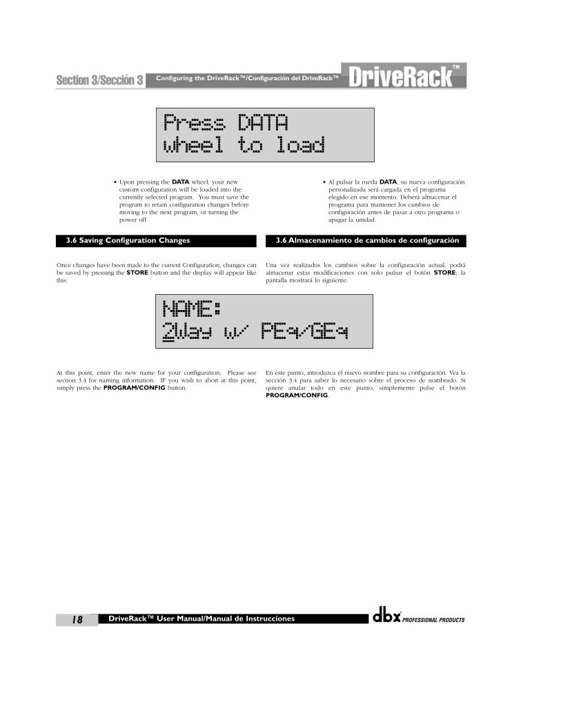
Configuring the DriveRack™/Configuración del DriveRack™
®
18
Section 3/Sección 3 DriveRack™
• Upon pressing the DATA wheel, your newcustom configuration will be loaded into thecurrently selected program. You must save theprogram to retain configuration changes beforemoving to the next program, or turning thepower off.
Once changes have been made to the current Configuration, changes canbe saved by pressing the STORE button and the display will appear likethis:
At this point, enter the new name for your configuration. Please seesection 3.4 for naming information. IF you wish to abort at this point,simply press the PROGRAM/CONFIG button.
• Al pulsar la rueda DATA, su nueva configuraciónpersonalizada será cargada en el programaelegido en ese momento. Deberá almacenar elprograma para mantener los cambios deconfiguración antes de pasar a otro programa oapagar la unidad.
Una vez realizados los cambios sobre la configuración actual, podráalmacenar estas modificaciones con solo pulsar el botón STORE; lapantalla mostrará lo siguiente:
En este punto, introduzca el nuevo nombre para su configuración. Vea lasección 3.4 para saber lo necesario sobre el proceso de nombrado. Siquiere anular todo en este punto, simplemente pulse el botónPROGRAM/CONFIG.
DriveRack™ User Manual/Manual de Instrucciones
3.6 Saving Configuration Changes 3.6 Almacenamiento de cambios de configuración
Press DATAwheel to load
NAME:2Way w/ PEq/GEq

DETAILED
PARAMETERS
PARAMETROS
DETALLADOS
®
PARAMETERS/PARAMETROSSection 4/Sección 4DriveRack™
Detailed Parameters/Parametros Detallados
®
20
DriveRack™
DriveRack™ User Manual/Manual de Instrucciones
Section 4/Sección 4The DriveRack™ units (240 and 241) offer complete editing flexibility, byoffering in-depth control over every parameter within each effect module.The following section will provide you with descriptions and explanationsof all parameters within the DriveRack™ units.
The signal routing begins at the INPUT ROUTING block of theDriveRack™ units. The input is configured as a mixer. These parametersare user adjustable on all programs. Please see section A.9 of theAppendix section for a complete input signal routing diagram.
InputThis parameter is used to select the input channel. Notice that bothchannel 1 and channel 2 are available for editing when the inputmodule is selected.
Level -Inf to 20dB This parameter is used to adjust the level for the selected channel.
Master level -Inf to 20dB This parameter is used to control the overall output level of the mixedinput signals.
The 240 and 241 DriveRack™ Pre-Crossover EQ sections may beconfigured as a single 31 band graphic or 9 band parametric. For moreinformation on these configuration options, please see section 3.5B.
4.2.1 - 31 BAND GRAPHIC EQ (G)EQ On/OffTurns the GEQ on and off.
Flatten/RestoreThis parameter either flattens the GEQ or restores the GEQ to the lastsaved shape. The DriveRack unit allows you to leave the EQ edit windowand return without losing the edited EQ settings.
Frequency (F) 20Hz to 20kHzThis parameter allows you to select any one the 31 available frequencies.
Gain (G) -12 to +12 dBThis parameter allows you to adjust the level of any one of the 31 bandsof the GEQ in .5 dB increments.
4.2.2 - PARAMETRIC EQ (P)EQ On/OffTurns the PEQ on and off.
Type Const Q Const Q operates similar to an analog graphic EQ where the Q is constantregardless of cut or boost.
Las unidades DriveRack™ (240 y 241) le ofrecen una total flexibilidad deedición, permitiéndole un control completo de cada uno de losparámetros dentro de cada módulo de efectos. En la sección siguiente leofrecemos descripciones y explicaciones de todos los parámetros quepuede encontrar en las unidades DriveRack™.
El direccionamiento de señal empieza en el bloque INPUT ROUTING de lasunidades DriveRack™. La entrada puede ser configurada como un router deseñal o un mezclador. Estos parámetros son ajustables por el usuario entodos los programas. Vaya a la sección A.9 del Apéndice si quiere ver undiagrama completo del direccionamiento de la señal de entrada.
EntradaEste parámetro se usa para seleccionar el canal de entrada. Tenga encuenta que cuando elija el módulo de entrada tendrá disponibles parasu edición tanto el canal 1 como el 2.
Nivel -Infinito hasta 20 dBEste parámetro se usa para ajustar el nivel del canal elegido.
Nivel principal -Infinito hasta 20 dB This parameter is used to control the overall output level of the mixedinput signals.
Las secciones de ecualización del DriveRack™ 240 y 241 pueden serconfiguradas como un ecualizador gráfico de 31 bandas sencillo o unoparamétrico de 9 bandas. Para más información sobre estas opciones deconfiguración, vea la sección 3.5B.
4.2.1 - ECUALIZADOR GRÁFICO DE 31 BANDAS (G)EQ On/OffActiva y desactiva el GEQ
Plano / RestaurarEste parámetro ajusta a plano el GEQ o restaura el GEQ a la última formaalmacenada. La unidad DriveRack le permite salir de la ventana deedición de EQ y volver a ella sin perder los ajustes EQ editados.
Frecuencia (F) 20 Hz hasta 20 kHzEste parámetro le permite elegir cualquiera de las 31 frecuenciasdisponibles.
Ganancia –12 hasta +12 dBEste parámetro le permite ajustar el nivel de cualquiera de las 31 bandasdel GEQ en incrementos de .5dB
4.2.2 - ECUALIZADOR PARAMETRICO (P)EQ On/OffActiva y desactiva el PEQ.
Tipo Const QConst Q funciona de forma similar a un ecualizador gráfico analógico en
el que Q es constante independientemente del corte o realce.
4.1 Input Routing
4.2 Pre-Crossover (EQ)
4.1 Direccionamiento de entrada
4.2 Pre-Crossover (ecualizador)
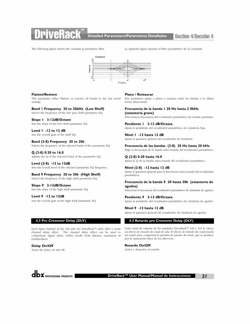
®
Detailed Parameters/Parametros Detallados Section 4/Sección 4DriveRack™
21DriveRack™ User Manual/Manual de Instrucciones
The following figure shows the constant Q parametric filter.
Flatten/RestoreThis parameter either flattens or restores all bands to the last savedsettings.
Band 1 Frequency 20 to 20kHz (Low Shelf)Selects the frequency of the low pass shelf parametric EQ.
Slope 1 3-12dB/OctaveSets the slope of the low shelf parametric EQ.
Level 1 -12 to 12 dBSets the overall gain of the shelf EQ.
Band (2-8) Frequency 20 to 20kSelects the frequency of the selected band of the parametric EQ.
Q (2-8) 0.20 to 16.0Adjusts the Q of the selected band of the parametric EQ.
Level (2-8) -12 to 12dBSets the overall level of the selected parametric EQ frequency.
Band 9 Frequency 20 to 20k (High Shelf)Selects the frequency of the high shelf parametric EQ.
Slope 9 3-12dB/OctaveSets the slope of the high shelf parametric EQ.
Level 9 -12 to 12dBSets the overall gain of the high shelf parametric EQ.
Each input channel of the 240 and 241 DriveRack™ units offer a roomchannel delay effect. The channel delay effect can be used tocompensate signal delay, which results from distance separation ofloudspeakers.
Delay On/OffTurns the delay on and off.
La siguiente figura muestra el filtro paramétrico de Q constante.
Plano / RestaurarEste parámetro ajusta a plano o restaura todas las bandas a la últimaforma almacenada.
Frecuencia de la banda 1 20 Hz hasta 2 0kHz(estantería grave)Selecciona la frecuencia del ecualizador paramétrico de estante pasabajos.
Pendiente 1 3-12 dB/OctavaAjusta la pendiente del ecualizador paramétrico de estantería baja.
Nivel 1 -12 hasta 12 dBAjusta la ganancia general del ecualizador de estantería.
Frecuencia de las bandas (2-8) 20 Hz hasta 20 kHzElige la frecuencia de la banda seleccionada del ecualizador paramétrico.
Q (2-8) 0.20 hasta 16.0Ajusta la Q de la banda seleccionada del ecualizador paramétrico.
Nivel (2-8) -12 hasta 12 dBAjusta la ganancia general para la frecuencia seleccionada del ecualizadorparamétrico.
Frecuencia de la banda 9 20 hasta 20k (estantería deagudos)Selecciona la frecuencia del ecualizador paramétrico de estantería de agudos.
Pendiente 9 3-12 dB/OctavaAjusta la pendiente del ecualizador paramétrico de estantería de agudos.
Nivel 9 -12 hasta 12 dBAjusta la ganancia general del ecualizador de estantería de agudos.
Cada canal de entrada de las unidades DriveRack™ 240 y 241 le ofreceun efecto de retardo de canal de sala. El efecto de retardo de canal puedeser usado para compensar la pérdida de retardo de señal, que se producepor la separación física de los altavoces.
Retardo On/OffActiva y desactiva el retardo.
4.3 Pre Crossover Delay (DLY) 4.3 Retardo pre Crossover Delay (DLY)
Detailed Parameters/Parametros Detallados
®
22
DriveRack™
DriveRack™ User Manual/Manual de Instrucciones
Section 4/Sección 4
Units - MilliSeconds, Feet or MetersSelects the unit of measurement for the delay.
LengthSelects the amount of delay. Delay length will correspond directly withthe selected unit of measurement. Max Delay lengths are: 1.0 second,1127 feet or 343 meters. Adjustments are in approximately 20 micro-second increments. Note:When using a 2x4 crossover, the predelay for the subs is taken fromchannel 1.
To accommodate any audio application, the 240 and 241 DriveRack™units offer numerous crossover options. There are three main types ofconfigurations found in the crossover section. They are: Wires, Filters andCrossovers. The Wire modules simply route the signal to the appropriateoutput with no processing. The filter module allows the user to select aWire and a high or low band pass filter with adjustable frequency andslope. The Dual filter is a case that splits the signal with the same filteron each output channel. The Crossover options are grouped into 2, 3 or4 band categories. Each Crossover gives control of 1, 2 or 3 crossoverpoints respectively. A crossover point is where the Lowpass andHighpass filter meet. The user may control the Lowpass edge, orHighpass edge. The Crossover type allows selection of Butterworth,Bessel or Linkwitz-Riley filter types with roll-off or slopes of 6-24dB/Octave (Butterworth and Bessel) or 12-24dB/Octave (Linkwitz-Riley). In traditional analog Crossovers using Linkwitz-Riley filters, thelow and high frequencies and slopes are set equal. Within the Crossovermenu, the following parameters are available with various Crossovers.
A complete diagram of each crossover used in the 240 and 241DriveRack™ units can be found in section A.7 of the Appendix.
4.4.1 MONO, DUAL TRI AND QUAD FILTERSFilter Type - Wire, Lowpass, Highpass and BandpassSelects the desired filter type.
Lowpass - 20Hz to 20kHz, or OutSelects the desired Lowpass crossover frequency, or allows you tocompletely remove the rolloff point.
Highpass - 20Hz to 20kHz, or OutSelects the desired Lowpass crossover frequency, or allows you tocompletely remove the rolloff point.
Low Slope - 6-24dB/Octave (filter type dependent) Sets the Lowpass slope of the crossover filter.
High Slope - 6-24dB/Octave Sets the Highpass slope of the crossover filter.
Type - Butterworth (BW), Bessel (BS) and Linkwitz-Riley(L-R)Selects the desired crossover filter type.
Unidades - Milisegundos, Mies o MetrosElige la unidad de medida del retardo.
LongitudElige la cantidad de retardo. La longitud del retardo se corresponderádirectamente con la unidad de medida elegida. Las longitudes de retardomáximas son: 1.0 segundos, 1127 pies o 343 metros.Los ajustes pueden ser realizados en incrementos de aproximadamente 20microsegundos cada uno. Nota: Cuando esté usando un crossover 2x4, elpre-retardo para los subs viene del canal 1.
Para adaptarse a cualquier aplicación de audio, las unidades DriveRack™disponen de diversas opciones de crossover o separadores defrecuencias. Hay tres tipos principales de configuraciones que seencuentran en la sección de crossover. Son: wires, filters y crossovers. Losmódulos wires (cables) simplemente dirigen la señal a la salida adecuadasin procesarla. El módulo filter (filtro) permite que el usuario elija un“cable” y un filtro pasa-alto o pasabajos con frecuencia y pendienteajustables. El filtro dual es un caso que divide la señal con un filtro encada canal. Las opciones de crossover están agrupadas en 2, 3 o 4categorías de bandas. Cada crossover da control de 1, 2 ó 3 puntos decrossover respectivamente. Un punto de crossover es el lugar en el quecoinciden los filtros pasabajos y pasa-altos. El usuario puede controlar elextremo pasabajos, o el extremo pasa-altos. El tipo de crossover permitela selección de filtros de tipos Butterworth, Bessel o Linkwitz-Riley consupresiones o pendientes de 6-24 dB/octava (Butterworth y Bessel) o 12-24 dB/Octava (Linkwitz-Riley). En los crossover analógicos tradicionalesque usan filtros Linkwitz-Riley, las frecuencias graves y agudas y laspendientes son ajustadas al mismo valor. Con el menú Crossover, disponede los siguientes parámetros con los distintos crossovers.
En la sección A.7 del Apéndice puede encontrar un diagrama completode cada crossover usado en las unidades DriveRack™ 240 y 241.
4.4.1 FILTROS MONO, DUAL,TRIY QUADTipo de filtro - Cable, Pasabajos, Pasa-altos, PasabandaElige el tipo deseado de filtro.
Pasabajos - 20 Hz a 20 kHz, o FueraElige la frecuencia de crossover pasabajo deseada, o le permite eliminarcompletamente el punto de supresión.
Pasa-altos - 20 Hz a 20 kHz, o FueraElige la frecuencia de crossover pasa-altos deseada, o le permite eliminarcompletamente el punto de supresión.
Pendiente graves - 6-24 dB/Octava (depende del tipode filtro) Ajusta la pendiente pasabajo del filtro crossover.
Pendiente agudos - 6-24 dB/Octava Ajusta la pendiente pasa-altos del filtro crossover.
Tipo - Butterworth (BW), Bessel (BS) and Linkwitz-Riley(L-R)Elige el tipo de filtro de crossover que quiera.
4.4 CROSSOVER (XOVER) 4.4 CROSSOVER (XOVER)
®
Detailed Parameters/Parametros Detallados Section 4/Sección 4DriveRack™
23DriveRack™ User Manual/Manual de Instrucciones
4.4.2 LINKED STEREO FILTERFilter Type 1 - Wire, Lowpass, Highpass and BandpassSelects the desired filter type.
Lowpass 1 - 20Hz to 20kHzSelects the desired Lowpass crossover frequency.
Highpass 1 - 20Hz to 20kHzSelects the desired Highpass crossover frequency.
Low Slope 1 - 6-24dB/Octave (filter type dependent) Sets the Lowpass slope of the crossover filter.
High Slope 1 - 6-24dB/Octave Sets the High pass slope of the crossover filter.
Type - Butterworth (BW), Bessel (BS) and Linkwitz-Riley(L-R)Selects the desired crossover filter type.
4.4.3 2-BAND CROSSOVERS - 1X2, 2X4Low Frequency rolloff 1 - 20Hz to 20kHzSelects the desired Lowpass crossover frequency.
High Frequency rolloff 1 - 20Hz to 20kHzSelects the desired Highpass crossover frequency.
Type 1 - Butterworth (BW), Bessel (BS) and Linkwitz-Riley(L-R)Selects the desired crossover filter type.
Low Slope 1 - 6-24dB/Octave (BW, Bessel) 12-48dB/Octave (L-R) Sets the Lowpass slope of the crossover filter.
High Slope 1 - 6-24dB/Octave (BW, Bessel) 12-48dB/Octave (L-R) Sets the Highpass slope of the crossover filter.
Low Frequency rolloff 2 - 20Hz to 20kHzSelects the desired Lowpass crossover frequency.
High Frequency rolloff 2 - 20Hz to 20kHzSelects the desired Highpass crossover frequency.
Type 2 - Butterworth (BW), Bessel (BS) and Linkwitz-Riley(L-R)Selects the desired crossover filter type.
Low Slope 2 - 6-24dB/Octave (BW, Bessel) 12-48dB/Octave (L-R) Sets the Lowpass slope of the crossover filter.
High Slope 2 - 6-24dB/Octave (BW, Bessel) 12-48dB/Octave (L-R) Sets the Highpass slope of the crossover filter.
4.4.2 FILTRO STEREO ENLAZADOTipo de filtro 1 - Cable, Pasabajo, Pasa-altos, PasabandaElige el tipo de filtro deseado.
Pasabajo 1 - 20 Hz a 20 kHzElige la frecuencia de crossover pasabajo deseada.
Pasa-altos 1 - 20 Hz a 20 kHzElige la frecuencia de crossover pasa-altos deseada.
Pendiente graves 1 - 6-24 dB/Octava (depende deltipo de filtro) Ajusta la pendiente pasabajo del filtro crossover.
Pendiente agudos 1 - 6-24 dB/Octava Ajusta la pendiente pasa-altos del filtro crossover.
Tipo - Butterworth (BW), Bessel (BS) and Linkwitz-Riley(L-R)Elige el tipo de filtro de crossover que quiera.
4.4.3 CROSSOVERS DE 2 BANDAS - 1X2, 2X4Frecuencia supresión graves 1 - 20 Hz hasta 20 kHzElige la frecuencia de crossover de pasabajos deseada.
Frecuencia supresión agudos 1 - 20 Hz hasta 20 kHzElige la frecuencia de crossover de pasa-altos deseada.
Tipo 1 - Butterworth (BW), Bessel (BS) and Linkwitz-Riley(L-R)Elige el tipo de filtro crossover deseado.
Pendiente graves 1 - 6-24 dB/Octava (BW, Bessel) 12-48 dB/Octava (L-R) Ajusta la pendiente de pasabajo del filtro crossover.
Pendiente agudos 1 - 6-24 dB/Octava (BW, Bessel) 12-48 dB/Octava (L-R) Ajusta la pendiente de pasa-alto del filtro crossover
Frecuencia supresión graves 2 - 20 Hz hasta 20 kHzElige la frecuencia de crossover de pasabajos deseada.
Frecuencia supresión agudos 2 - 20 Hz hasta 20 kHzElige la frecuencia de crossover de pasa-altos deseada.
Tipo 2 - Butterworth (BW), Bessel (BS) and Linkwitz-Riley(L-R)Elige el tipo de filtro crossover deseado.
Pendiente graves 2 - 6-24 dB/Octava (BW, Bessel) 12-48 dB/Octava(L-R) Ajusta la pendiente de pasabajo del filtro crossover.
Pendiente agudos 2 - 6-24 dB/Octava (BW, Bessel) 12-48 dB/Octava (L-R) Ajusta la pendiente de pasa-alto del filtro crossover.
Detailed Parameters/Parametros Detallados
®
24
DriveRack™
DriveRack™ User Manual/Manual de Instrucciones
Section 4/Sección 4
4.4.4 3-BAND CROSSOVERS - 1X3Low Frequency rolloff 1 - 20Hz to 20kHzSelects the desired Lowpass crossover frequency.
High Frequency rolloff 1 - 20Hz to 20kHzSelects the desired Highpass crossover frequency.
Type 1 - Butterworth (BW), Bessel and Linkwitz-Riley(L-R)Selects the desired cross-over filter type.
Low Slope 1 - 6-24dB/Octave (BW, Bessel) 12-24dB/Octave (L-R) Sets the slope of the crossover filter.
High Slope 1 - 6-24dB/Octave (BW, Bessel) 12-24dB/Octave (L-R) Sets the Highpass slope of the crossover filter.
Low Frequency rolloff 2 - 20Hz to 20kHzSelects the desired Lowpass crossover frequency.
High Frequency rolloff 2 - 20Hz to 20kHzSelects the desired Highpass crossover frequency.
Type 2 - Butterworth (BW), Bessel (BS) and Linkwitz-Riley(L-R)Selects the desired crossover filter type.
Low Slope 2 - 6-24dB/Octave (BW, Bessel) 12-24dB/Octave (L-R) Sets the Lowpass slope of the crossover filter.
High Slope 2 - 6-24dB/Octave (BW, Bessel) 12-24dB/Octave (L-R) Sets the Highpass slope of the crossover filter.
Low Frequency rolloff 3 - 20Hz to 20kHzSelects the desired Lowpass crossover frequency.
High Frequency rolloff 3 - 20Hz to 20kHzSelects the desired Highpass crossover frequency.
Type 3 - Butterworth (BW), Bessel (BS) and Linkwitz-Riley(L-R)Selects the desired crossover filter type.
Low Slope 3 - 6-24dB/Octave (BW, Bessel) 12-24dB/Octave (L-R) Sets the Lowpass slope of the crossover filter.
High Slope 3 - 6-24dB/Octave (BW, Bessel) 12-24dB/Octave (L-R) Sets the Highpass slope of the crossover filter.
4.4.5 4-BAND CROSSOVERS - 1X4Low Frequency rolloff 1 - 20Hz to 20kHzSelects the desired Lowpass crossover frequency.
4.4.4 CROSSOVERS DE 3 BANDAS - 1X3Frecuencia supresión graves 1 - 20 Hz hasta 20 kHzElige la frecuencia de crossover de pasabajos deseada.
Frecuencia supresión agudos 1 - 20 Hz hasta 20 kHzElige la frecuencia de crossover de pasa-altos deseada.
Tipo 1 - Butterworth (BW), Bessel and Linkwitz-Riley(L-R)Elige el tipo de filtro crossover deseado.
Pendiente graves 1 - 6-24 dB/Octava (BW, Bessel) 12-24 dB/Octava (L-R) Ajusta la pendiente de pasabajo del filtro crossover.
Pendiente agudos 1 - 6-24 dB/Octava (BW, Bessel) 12-24 dB/Octava (L-R) Ajusta la pendiente de pasa-alto del filtro crossover.
Frecuencia supresión graves 2 - 20 Hz hasta 20 kHzElige la frecuencia de crossover de pasabajos deseada.
Frecuencia supresión agudos 2 - 20 Hz hasta 20 kHzElige la frecuencia de crossover de pasa-altos deseada..
Tipo 2 - Butterworth (BW), Bessel (BS) and Linkwitz-Riley(L-R)Elige el tipo de filtro crossover deseado.
Pendiente graves 2 - 6-24 dB/Octava (BW, Bessel) 12-24 dB/Octava (L-R) Ajusta la pendiente de pasabajo del filtro crossover.
Pendiente agudos 2 - 6-24 dB/Octava (BW, Bessel) 12-24 dB/Octava (L-R) Ajusta la pendiente de pasa-alto del filtro crossover.
Frecuencia supresión graves 3 - 20 Hz hasta 20 kHzElige la frecuencia de crossover de pasabajos deseada.
Frecuencia supresión graves 3 - 20 Hz hasta 20 kHzElige la frecuencia de crossover de pasa-altos deseada.
Tipo 3 - Butterworth (BW), Bessel (BS) and Linkwitz-Riley(L-R)Elige el tipo de filtro crossover deseado.
Pendiente graves 3 - 6-24 dB/Octava (BW, Bessel) 12-24 dB/Octava (L-R) Ajusta la pendiente de pasabajo del filtro crossover.
Pendiente agudos 3 - 6-24 dB/Octava (BW, Bessel) 12-24 dB/Octava (L-R) Ajusta la pendiente de pasa-alto del filtro crossover.
4.4.5 CROSSOVERS DE 4 BANDAS - 1X4Frecuencia supresión gravesf 1 - 20 Hz hasta 20 kHzElige la frecuencia de crossover de pasabajos deseada.
®
Detailed Parameters/Parametros Detallados Section 4/Sección 4DriveRack™
25DriveRack™ User Manual/Manual de Instrucciones
High Frequency rolloff 1 - 20Hz to 20kHzSelects the desired Highpass crossover frequency.
Type 1 - Butterworth (BW), Bessel and Linkwitz-Riley(L-R)Selects the desired crossover filter type.
Low Slope 1 - 6-24dB/Octave (BW, Bessel) 12-24dB/Octave (L-R) Sets the Lowpass slope of the crossover filter.
High Slope 1 - 6-24dB/Octave (BW, Bessel) 12-24dB/Octave (L-R) Sets the Highpass slope of the crossover filter.
Low Frequency 2 - 20Hz to 20kHzSelects the desired Lowpass crossover frequency.
High Frequency 2 - 20Hz to 20kHzSelects the desired Highpass crossover frequency.
Type 2 - Butterworth (BW), Bessel and Linkwitz-Riley(L-R)Selects the desired crossover filter type.
Low Slope 2 - 6-24dB/Octave (BW, Bessel) 12-48dB/Octave (L-R) Sets the Lowpass slope of the crossover filter.
High Slope 2 - 6-24dB/Octave (BW, Bessel) 12-48dB/Octave (L-R) Sets the Highpass slope of the crossover filter.
Low Frequency rolloff 3 - 20Hz to 20kHzSelects the desired Lowpass crossover frequency.
High Frequency rolloff 3 - 20Hz to 20kHzSelects the desired Highpass crossover frequency.
Type 3 - Butterworth (BW), Bessel and Linkwitz-Riley(L-R)Selects the desired crossover filter type.
Low Slope 3 - 6-24dB/Octave (BW, Bessel) 12-24dB/Octave (L-R) Sets the Lowpass slope of the crossover filter.
High Slope 3 - 6-24dB/Octave (BW, Bessel) 12-24dB/Octave (L-R) Sets the Highpass slope of the crossover filter.
Low Frequency rolloff 4 - 20Hz to 20kHzSelects the desired Lowpass crossover frequency.
High Frequency rolloff 4 - 20Hz to 20kHzSelects the desired Highpass crossover frequency.
Frecuencia supresión agudos 1 - 20 Hz hasta 20 kHzElige la frecuencia de crossover de pasa-altos deseada.
Tipo 1 - Butterworth (BW), Bessel and Linkwitz-Riley(L-R)Elige el tipo de filtro crossover deseado.
Pendiente graves 1 - 6-24 dB/Octava (BW, Bessel) 12-24 dB/Octava (L-R) Ajusta la pendiente de pasabajo del filtro crossover.
Pendiente agudos 1 - 6-24 dB/Octava (BW, Bessel) 12-24 dB/Octava (L-R) Ajusta la pendiente de pasa-alto del filtro crossover.
Frecuencia supresión graves 2 - 20 Hz hasta 20 kHzElige la frecuencia de crossover de pasabajos deseada.
Frecuencia supresión agudos 2 - 20 Hz hasta 20 kHzElige la frecuencia de crossover de pasa-altos deseada.
Tipo 2 - Butterworth (BW), Bessel and Linkwitz-Riley(L-R)SElige el tipo de filtro crossover deseado.
Pendiente graves 2 - 6-24 dB/Octava (BW, Bessel) 12-48 dB/Octava (L-R) Ajusta la pendiente de pasabajo del filtro crossover.
Pendiente agudos 2 - 6-24 dB/Octava (BW, Bessel) 12-48 dB/Octava (L-R) Ajusta la pendiente de pasa-alto del filtro crossover.
Frecuencia supresión graves 3 - 20 Hz hasta 20 kHzElige la frecuencia de crossover de pasabajos deseada.
Frecuencia supresión agudos 3 - 20 Hz hasta 20 kHzElige la frecuencia de crossover de pasa-altos deseada.
Tipo 3 - Butterworth (BW), Bessel and Linkwitz-Riley(L-R)Elige el tipo de filtro crossover deseado.
Pendiente graves 3 - 6-24 dB/Octava (BW, Bessel) 12-24 dB/Octava (L-R) Ajusta la pendiente de pasabajo del filtro crossover.
Pendiente agudos 3 - 6-24 dB/Octava (BW, Bessel) 12-24 dB/Octava (L-R) Ajusta la pendiente de pasa-alto del filtro crossover.
Frecuencia supresión graves 4 - 20 Hz hasta 20 kHzElige la frecuencia de crossover de pasabajos deseada.
Frecuencia supresión agudos 4 - 20 Hz hasta 20 kHzElige la frecuencia de crossover de pasa-altos deseada.
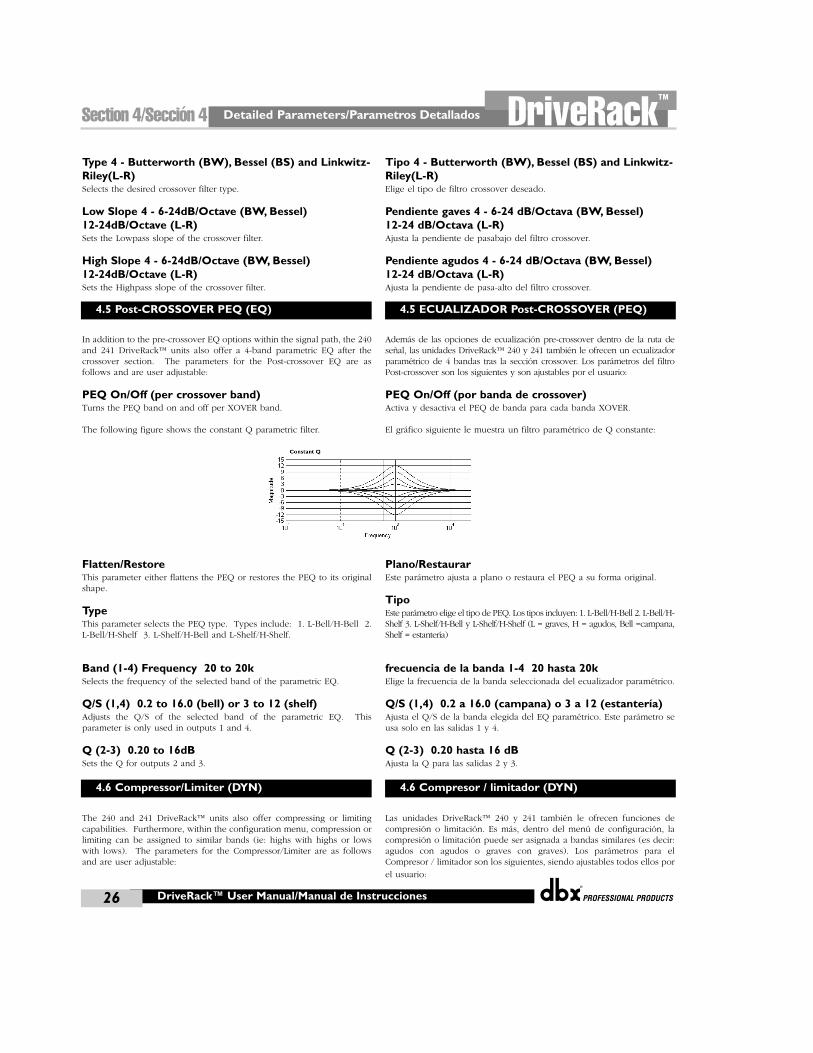
Detailed Parameters/Parametros Detallados
®
26
DriveRack™
DriveRack™ User Manual/Manual de Instrucciones
Section 4/Sección 4
Type 4 - Butterworth (BW), Bessel (BS) and Linkwitz-Riley(L-R)Selects the desired crossover filter type.
Low Slope 4 - 6-24dB/Octave (BW, Bessel) 12-24dB/Octave (L-R) Sets the Lowpass slope of the crossover filter.
High Slope 4 - 6-24dB/Octave (BW, Bessel) 12-24dB/Octave (L-R) Sets the Highpass slope of the crossover filter.
In addition to the pre-crossover EQ options within the signal path, the 240and 241 DriveRack™ units also offer a 4-band parametric EQ after thecrossover section. The parameters for the Post-crossover EQ are asfollows and are user adjustable:
PEQ On/Off (per crossover band)Turns the PEQ band on and off per XOVER band.
The following figure shows the constant Q parametric filter.
Flatten/RestoreThis parameter either flattens the PEQ or restores the PEQ to its originalshape.
TypeThis parameter selects the PEQ type. Types include: 1. L-Bell/H-Bell 2.L-Bell/H-Shelf 3. L-Shelf/H-Bell and L-Shelf/H-Shelf.
Band (1-4) Frequency 20 to 20kSelects the frequency of the selected band of the parametric EQ.
Q/S (1,4) 0.2 to 16.0 (bell) or 3 to 12 (shelf)Adjusts the Q/S of the selected band of the parametric EQ. Thisparameter is only used in outputs 1 and 4.
Q (2-3) 0.20 to 16dBSets the Q for outputs 2 and 3.
The 240 and 241 DriveRack™ units also offer compressing or limitingcapabilities. Furthermore, within the configuration menu, compression orlimiting can be assigned to similar bands (ie: highs with highs or lowswith lows). The parameters for the Compressor/Limiter are as followsand are user adjustable:
Tipo 4 - Butterworth (BW), Bessel (BS) and Linkwitz-Riley(L-R)Elige el tipo de filtro crossover deseado.
Pendiente gaves 4 - 6-24 dB/Octava (BW, Bessel) 12-24 dB/Octava (L-R) Ajusta la pendiente de pasabajo del filtro crossover.
Pendiente agudos 4 - 6-24 dB/Octava (BW, Bessel) 12-24 dB/Octava (L-R) Ajusta la pendiente de pasa-alto del filtro crossover.
Además de las opciones de ecualización pre-crossover dentro de la ruta deseñal, las unidades DriveRack™ 240 y 241 también le ofrecen un ecualizadorparamétrico de 4 bandas tras la sección crossover. Los parámetros del filtroPost-crossover son los siguientes y son ajustables por el usuario:
PEQ On/Off (por banda de crossover)Activa y desactiva el PEQ de banda para cada banda XOVER.
El gráfico siguiente le muestra un filtro paramétrico de Q constante:
Plano/RestaurarEste parámetro ajusta a plano o restaura el PEQ a su forma original.
TipoEste parámetro elige el tipo de PEQ. Los tipos incluyen: 1. L-Bell/H-Bell 2. L-Bell/H-Shelf 3. L-Shelf/H-Bell y L-Shelf/H-Shelf (L = graves, H = agudos, Bell =campana,Shelf = estantería)
frecuencia de la banda 1-4 20 hasta 20kElige la frecuencia de la banda seleccionada del ecualizador paramétrico.
Q/S (1,4) 0.2 a 16.0 (campana) o 3 a 12 (estantería)Ajusta el Q/S de la banda elegida del EQ paramétrico. Este parámetro seusa solo en las salidas 1 y 4.
Q (2-3) 0.20 hasta 16 dBAjusta la Q para las salidas 2 y 3.
Las unidades DriveRack™ 240 y 241 también le ofrecen funciones decompresión o limitación. Es más, dentro del menú de configuración, lacompresión o limitación puede ser asignada a bandas similares (es decir:agudos con agudos o graves con graves). Los parámetros para elCompresor / limitador son los siguientes, siendo ajustables todos ellos por
el usuario:
4.5 Post-CROSSOVER PEQ (EQ)
4.6 Compressor/Limiter (DYN)
4.5 ECUALIZADOR Post-CROSSOVER (PEQ)
4.6 Compresor / limitador (DYN)
®
Detailed Parameters/Parametros Detallados Section 4/Sección 4DriveRack™
27DriveRack™ User Manual/Manual de Instrucciones
Dynamics On/OffTurns the compressor/limiter module on and off.
Dynamics Select Compressor/LimiterWhen set to “comp,” the compressor is active. When set to “Lim,” thelimiter is active.
OverEasy Off to 10There are ten levels of OverEasy® that can be used for the limiters. Thepoint when the compressor starts to compress is the "knee." When thecompressor starts to reduce the level of a signal abruptly right as it passesover the threshold this is called "hard knee" compression. OverEasy®(soft knee as it is sometimes called) is when the volume of the sound iscompressed gradually. OverEasy® compression starts to compress beforethe level of the signal reaches the threshold and reaches full compressionafter the level has gone above the threshold. This OverEasy®compression, by its very nature sounds much smoother and more naturaland will be used for most applications. When it is gentle (naturalsounding or light) compression that you are looking for, the compressoroffers VariKnee™. VariKnee™ gives you ten levels of OverEasy®compression to choose from (1 being almost hard knee and 10 being themost OverEasy®). This lets you choose the exact knee that is needed forthe dynamic effect you are looking for.
Threshold -40 to +20dBuThreshold is the signal level at which the 240 and 241 DriveRack™ unitsstart to compress the signal. If the level is set to -10dBu, than any signallarger than -10dBu is compressed while any signal that has a level that islower than -10dBu is left at the same signal level. Light compression iswhere only the loudest parts of the signal go over the threshold. Veryheavy compression can be achieved by setting the threshold low enoughthat almost the entire signal content is over the threshold. For most signalsthe most natural compression is achieved when most of the signal contentremains just below the threshold and only the peaks cross the threshold.
Peakstop+ On/Off and 1-6This parameter turns the peakstop limiting on and off. Peakstop+ is onlyin effect when the ratio is set to INF:1 (Limiter). PeakStop+ is onlyavailable when the limiter is selected.
PeakStop+ involves a two-stage process of dynamic limiting. The firststage of PeakStop+ is the Instantaneous Transient Clamp™ which clampsthe signal with a soft logarithmic clamp function. This logarithmicfunction ensures that the signal will not exceed the level set by thePeakStop+™ LEVEL control by more than 2dB typically, and that it willnot introduce harsh artifacts. The second stage is a unique program limiterfeaturing Intelligent Predictive Limiting™. Its function is to monitor theinput signal and intelligently predict the amount of gain reduction neededto keep the output signal below the ceiling set by the InstantaneousTransient Clamp™. Note that since the PeakStop+™ limiter is a fail-safelimiter, it must come after the OUTPUT GAIN control.
Dynamics On/OffActiva y desactiva el módulo compresor / limitador
Dynamics Select Compressor/LimiterCuando lo ajusta a “comp”, el compresor está activo. Cuando lo ajuste a“Lim”, estará activo el limitador.
OverEasy Off hasta 10Hay diez niveles de OverEasy® que se pueden usar con los limitadores.El punto en el que el compresor empieza a comprimir es el “codo”. Almodo en el que el compresor empieza a reducir el nivel de una señal deforma abrupta justo cuando pasa por encima del umbral se le llamacompresión de “codo duro”. El modo OverEasy® (o de “codo suave”como se le suele llamar a veces) es cuando el volumen del sonido escomprimido de forma gradual. La compresión OverEasy® comienza antesde que el nivel de la señal alcance el umbral, llegando hasta lacompresión completa después de que el nivel haya sobrepasado elumbral. Esta compresión OverEasy®, por su propia naturaleza, produceun sonido mucho más suave y natural y será la que utilizará en la mayoríade aplicaciones. Cuando lo que busque sea una compresión suave(sonido natural o ligero), el compresor le ofrece la opción VariKnee™.Este VariKnee™ le ofrece diez niveles de compresión OverEasy® entre losque elegir (el valor 1 es casi de “codo duro” mientras que el 10 es casiOverEasy®). Esto le permite elegir el tipo de codo o punto de inflexiónexacto que necesite para el efecto de dinamismo que está buscando.
Umbral -40 hasta +20 dBuEl umbral es el nivel de señal en el que las unidades DriveRack™ 240 y241 comienzan a comprimir la señal. Si el nivel es ajustado a –10 dBu,entonces cualquier señal mayor de –10 dBu será comprimida mientrasque cualquier señal que tenga un nivel inferior a –10 dBu permanecerácon el mismo nivel de señal. La compresión ligera es aquella en la quesólo las partes más fuertes de la señal pasan por encima del umbral. Sepuede conseguir una compresión muy fuerte ajustando el umbral losuficientemente bajo como para que casi todo el contenido de la señalesté por encima del umbral. Para la mayoría de señales la compresiónmás natural se obtiene cuando la mayor parte del contenido de la señalpermanece justo por debajo del umbral y sólo los picos lo sobrepasan.
Tope de picos+ On/Off y 1-6Este parámetro activa y desactiva el limitador con tope de picos. Estaopción es el único efecto disponible cuando la relación o ratio es fijadoa INF:1 (limitador).
El Peakstop+ implica un proceso de limitación dinámica de dos fases. Laprimera fase de este Peakstop+ la Sujeción instantánea de transitorios‰que se ocupa de “sujetar” la señal con una suave función logarítmica detipo abrazadera. Esta función logarítmica asegura que la señal nosobrepasará el nivel ajustado por el control Peakstop+‰ LEVEL en másde 2 dB de forma típica, y que a la vez no se introducirá ningún tipo deruido. La segunda fase es una función de limitador de programarealmente única llamada Limitación de anticipación inteligente‰. Estafunción se ocupa de monitorizar la señal de entrada y predecir de formainteligente la cantidad de reducción de ganancia necesaria para mantenerla señal de salida por debajo del techo ajustado en la fase anterior. Tengaen cuenta que dado que el limitador Peakstop+‰ es un limitador seguro,debe ir detrás del control OUTPUT GAIN de ganancia de salida.

Detailed Parameters/Parametros Detallados
®
28
DriveRack™
DriveRack™ User Manual/Manual de Instrucciones
Section 4/Sección 4
Ratio 1.0 to Inf:1Ratio is the amount the 240 and 241 DriveRack™ units reduce the signallevel of the sound that is above the threshold. A 2:1 ratio means that ifthe incoming signal is 2dB over the threshold the 240 and 241DriveRack™ units will compress the signal, and outputs a signal that onlygoes 1dB over the threshold. For light compression choose a lower ratio,while a heavy compression requires a higher ratio. A setting of Inf:1 setsthe compressor act as a limiter.
Gain -20 to +20dBThis parameter is used to compensate for the gain lost duringcompression. By using heavy compression on a signal and then boostingthe signal with the output gain, the user can create a signal that soundsmuch louder than it actually is.
The 240 and 241 DriveRack™ units also offer a speaker alignment delaywhich is located after the crossover section. This delay is ideal to use forcompensating signal delay that occurs between speaker drivercomponents such as speaker clusters or between internal speakercomponents such as high frequency, mid frequency and low frequencydrivers within a speaker cabinet.
Delay On/Off Turns the Speaker Alignment delay on and off.
Units - MS (milliseconds), Feet or MetersSelects the unit of measurement for the delay.
LengthSets the amount of Speaker Alignment delay time. Delay times include:Seconds- 0-365.32 ms, Feet- 0-411.72 and Meters - 0.0-125.31. Fineadjustments are made in 10 microsecond increments.
The output section 240 and 241DriveRack™ units provide the user withthe ability to control output levels of the unit and adjust phasecompensation of loudspeakers within the signal path. The parameters forthe Phase Compensation effect are as follows and are user adjustable.Please refer to section A.9 of the Appendix for a complete output signalrouting diagram.
Output Adjust On/OffThis parameter is used to turn the selected output level and shiftparameters on or off. When level/shift is off, level is set to 0dB and phaseshift is 00.
Gain -Inf to 20.0dBThis parameter is used to set the overall output level of the selectedoutput.
Phase Off, 0 to -3600
Sets the amount of phase within the selected output path. The phase isreferenced to the upper frequency of the selected output crossover band.
Ratio 1.0 hasta Inf:1El Ratio o relación es la cantidad en que las unidades DriveRack™reducen el nivel de señal del sonido que está por encima del umbral. Unarelación 2:1 significa que si la señal entrante está 2 dB por encima delumbral, las unidades DriveRack™ 240 y 241 comprimirán la señal, yemitirán una señal con sólo 1dB por encima del umbral. Para unacompresión ligera elija un ratio menor, mientras que las compresionesfuertes obligarán a valores altos. Un ajuste Inf:1 hace que el compresoractúe como un limitador.
Gain -20 hasta +20 dBEste parámetro se usa para compensar la ganancia perdida durante lacompresión. Usando una compresión fuerte en una señal y despuésrealzándola con la ganancia de salida, el usuario puede crear una señalque suene mucho más fuerte de lo que realmente era.
Las unidades DriveRack™ 240 y 241 también disponen de un retardo dealineación de altavoces situado tras la sección de crossover. Este retardoes ideal para su uso en la compensación del retardo de señal que seproduce entre las distintas unidades que forman un bloque de recintos oentre los componentes internos de los recintos acústicos como lastrompetas, altavoces y subwoofers que se encuentran dentro de la caja orecinto.
Retardo On/Off Activa y desactiva el retardo de alineación de altavoces.
Unidades - MS (milisegundos), Pies o MetrosSelects the unit of measurement for the delay.
LongitudElige la cantidad de tiempo de retardo de alineación de altavoces.Segundos: 0-365.32ms, Pies: 0-411.72 y Metros: 0.0-125.31. Los ajustes másprecisos se realizan en incrementos de 10 microsegundos.
La sección de salida de las unidades DriveRack™ 240 y 241 le ofrecen alusuario la capacidad de controlar los niveles de salida de la unidad yajustar la compensación de fase de altavoces dentro de la ruta de señal.Los parámetros para el efecto de compensación de fase son los que leindicamos a continuación, siendo todos ajustables por el usuario. Vaya ala sección A.9 del apéndice para ver un completo diagrama de ruta deseñal de salida.
Ajuste de salida On/OffEste parámetro se usa para activar o desactivar los parámetros de cambioy el nivel de salida elegido. Cuando el nivel / cambio está en off, el niveles ajustado a 0 dB y el cambio de fase es 0º.
Ganancia -Infinito a 20.0 dBEste parámetro se usa para ajustar el nivel de salida global de la salidaelegida.
Fase Off, 0 a -3600
Ajusta la cantidad de fase dentro de la ruta de salida elegida. La fase tomasu referencia de la frecuencia superior de la banda de crossover de salidaelegida.
4.7 Speaker Alignment Delay (DLY)
4.8 Output Routing
4.7 Retardo de alineación de altavoces (DLY)
4.8 Direccionamiento de salida
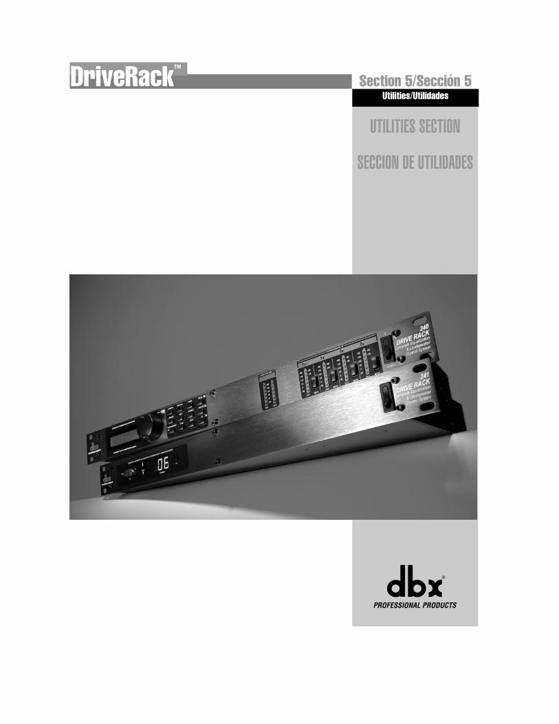
UTILITIES SECTION
SECCION DE UTILIDADES
®
Utilities/UtilidadesSection 5/Sección 5DriveRack™
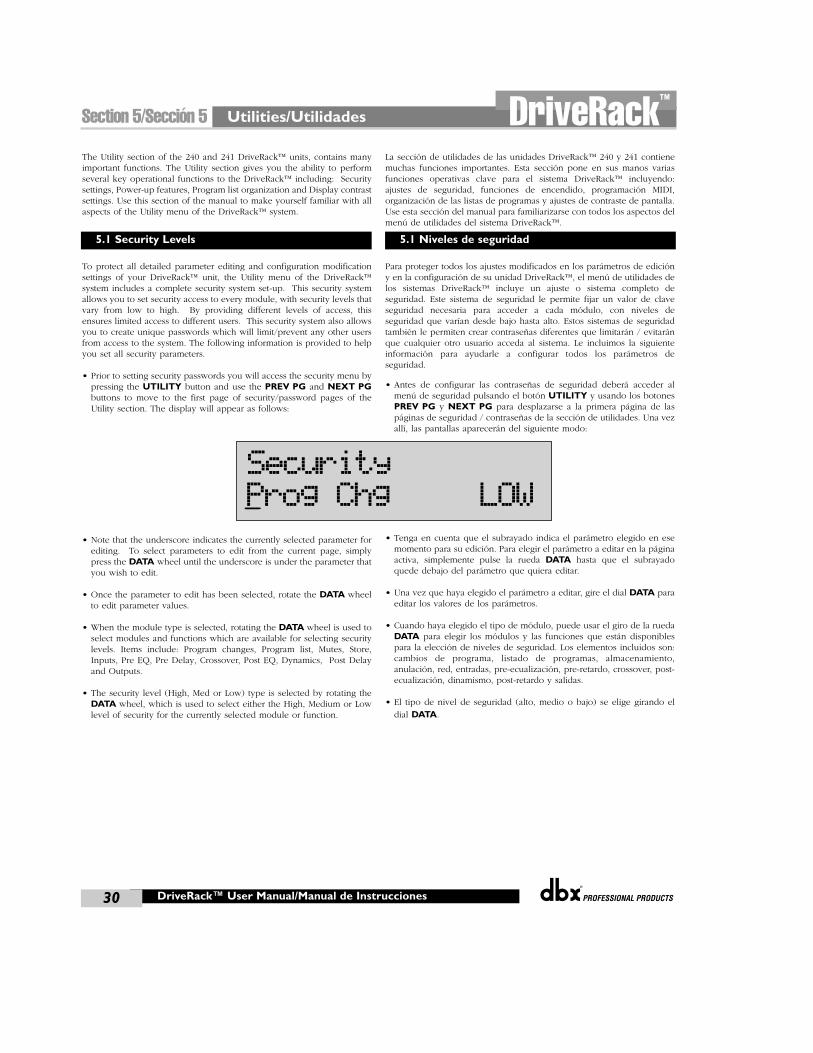
Utilities/Utilidades
®
30
Section 5/Sección 5 DriveRack™
®
DriveRack™ User Manual/Manual de Instrucciones
The Utility section of the 240 and 241 DriveRack™ units, contains manyimportant functions. The Utility section gives you the ability to performseveral key operational functions to the DriveRack™ including: Securitysettings, Power-up features, Program list organization and Display contrastsettings. Use this section of the manual to make yourself familiar with allaspects of the Utility menu of the DriveRack™ system.
To protect all detailed parameter editing and configuration modificationsettings of your DriveRack™ unit, the Utility menu of the DriveRack™system includes a complete security system set-up. This security systemallows you to set security access to every module, with security levels thatvary from low to high. By providing different levels of access, thisensures limited access to different users. This security system also allowsyou to create unique passwords which will limit/prevent any other usersfrom access to the system. The following information is provided to helpyou set all security parameters.
• Prior to setting security passwords you will access the security menu bypressing the UTILITY button and use the PREV PG and NEXT PGbuttons to move to the first page of security/password pages of theUtility section. The display will appear as follows:
• Note that the underscore indicates the currently selected parameter forediting. To select parameters to edit from the current page, simplypress the DATA wheel until the underscore is under the parameter thatyou wish to edit.
• Once the parameter to edit has been selected, rotate the DATA wheelto edit parameter values.
• When the module type is selected, rotating the DATA wheel is used toselect modules and functions which are available for selecting securitylevels. Items include: Program changes, Program list, Mutes, Store,Inputs, Pre EQ, Pre Delay, Crossover, Post EQ, Dynamics, Post Delayand Outputs.
• The security level (High, Med or Low) type is selected by rotating theDATA wheel, which is used to select either the High, Medium or Lowlevel of security for the currently selected module or function.
La sección de utilidades de las unidades DriveRack™ 240 y 241 contienemuchas funciones importantes. Esta sección pone en sus manos variasfunciones operativas clave para el sistema DriveRack™ incluyendo:ajustes de seguridad, funciones de encendido, programación MIDI,organización de las listas de programas y ajustes de contraste de pantalla.Use esta sección del manual para familiarizarse con todos los aspectos delmenú de utilidades del sistema DriveRack™.
Para proteger todos los ajustes modificados en los parámetros de edicióny en la configuración de su unidad DriveRack™, el menú de utilidades delos sistemas DriveRack™ incluye un ajuste o sistema completo deseguridad. Este sistema de seguridad le permite fijar un valor de claveseguridad necesaria para acceder a cada módulo, con niveles deseguridad que varían desde bajo hasta alto. Estos sistemas de seguridadtambién le permiten crear contraseñas diferentes que limitarán / evitaránque cualquier otro usuario acceda al sistema. Le incluimos la siguienteinformación para ayudarle a configurar todos los parámetros deseguridad.
• Antes de configurar las contraseñas de seguridad deberá acceder almenú de seguridad pulsando el botón UTILITY y usando los botonesPREV PG y NEXT PG para desplazarse a la primera página de laspáginas de seguridad / contraseñas de la sección de utilidades. Una vezallí, las pantallas aparecerán del siguiente modo:
• Tenga en cuenta que el subrayado indica el parámetro elegido en esemomento para su edición. Para elegir el parámetro a editar en la páginaactiva, simplemente pulse la rueda DATA hasta que el subrayadoquede debajo del parámetro que quiera editar.
• Una vez que haya elegido el parámetro a editar, gire el dial DATA paraeditar los valores de los parámetros.
• Cuando haya elegido el tipo de módulo, puede usar el giro de la ruedaDATA para elegir los módulos y las funciones que están disponiblespara la elección de niveles de seguridad. Los elementos incluidos son:cambios de programa, listado de programas, almacenamiento,anulación, red, entradas, pre-ecualización, pre-retardo, crossover, post-ecualización, dinamismo, post-retardo y salidas.
• El tipo de nivel de seguridad (alto, medio o bajo) se elige girando el
dial DATA.
5.1 Security Levels 5.1 Niveles de seguridad
SecurityProg Chg LOW
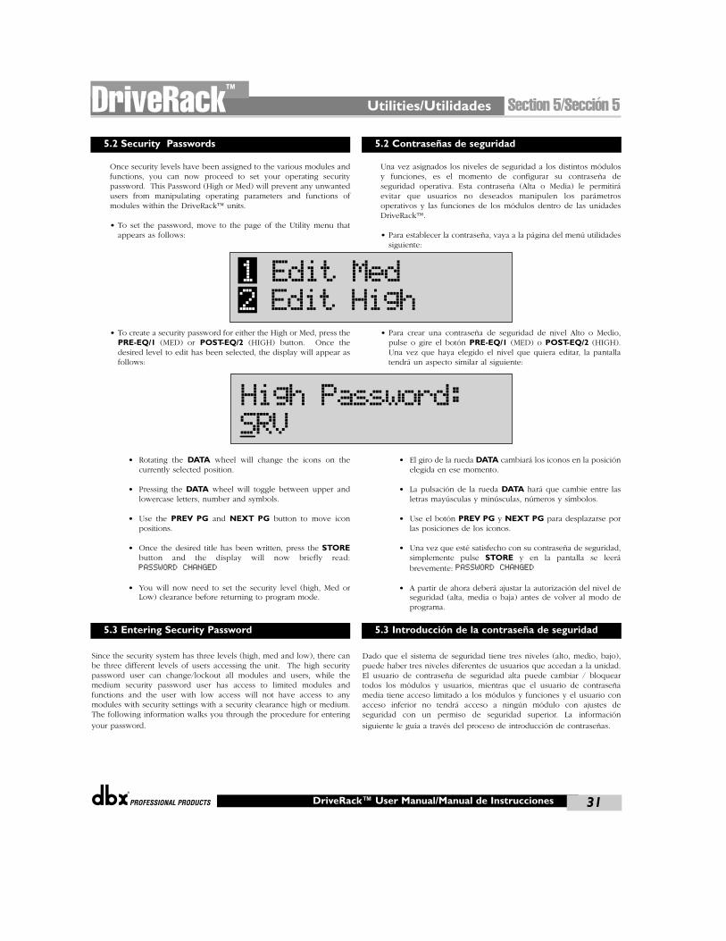
®
Utilities/Utilidades Section 5/Sección 5DriveRack™
31®
DriveRack™ User Manual/Manual de Instrucciones
Once security levels have been assigned to the various modules andfunctions, you can now proceed to set your operating securitypassword. This Password (High or Med) will prevent any unwantedusers from manipulating operating parameters and functions ofmodules within the DriveRack™ units.
• To set the password, move to the page of the Utility menu thatappears as follows:
• To create a security password for either the High or Med, press thePRE-EQ/1 (MED) or POST-EQ/2 (HIGH) button. Once thedesired level to edit has been selected, the display will appear asfollows:
• Rotating the DATA wheel will change the icons on thecurrently selected position.
• Pressing the DATA wheel will toggle between upper andlowercase letters, number and symbols.
• Use the PREV PG and NEXT PG button to move iconpositions.
• Once the desired title has been written, press the STOREbutton and the display will now briefly read:PASSWORD CHANGED
• You will now need to set the security level (high, Med orLow) clearance before returning to program mode.
Since the security system has three levels (high, med and low), there canbe three different levels of users accessing the unit. The high securitypassword user can change/lockout all modules and users, while themedium security password user has access to limited modules andfunctions and the user with low access will not have access to anymodules with security settings with a security clearance high or medium.The following information walks you through the procedure for entering
your password.
Una vez asignados los niveles de seguridad a los distintos módulosy funciones, es el momento de configurar su contraseña deseguridad operativa. Esta contraseña (Alta o Media) le permitiráevitar que usuarios no deseados manipulen los parámetrosoperativos y las funciones de los módulos dentro de las unidadesDriveRack™.
• Para establecer la contraseña, vaya a la página del menú utilidadessiguiente:
• Para crear una contraseña de seguridad de nivel Alto o Medio,pulse o gire el botón PRE-EQ/1 (MED) o POST-EQ/2 (HIGH).Una vez que haya elegido el nivel que quiera editar, la pantallatendrá un aspecto similar al siguiente:
• El giro de la rueda DATA cambiará los iconos en la posiciónelegida en ese momento.
• La pulsación de la rueda DATA hará que cambie entre lasletras mayúsculas y minúsculas, números y símbolos.
• Use el botón PREV PG y NEXT PG para desplazarse porlas posiciones de los iconos.
• Una vez que esté satisfecho con su contraseña de seguridad,simplemente pulse STORE y en la pantalla se leerábrevemente: PASSWORD CHANGED
• A partir de ahora deberá ajustar la autorización del nivel deseguridad (alta, media o baja) antes de volver al modo deprograma.
Dado que el sistema de seguridad tiene tres niveles (alto, medio, bajo),puede haber tres niveles diferentes de usuarios que accedan a la unidad.El usuario de contraseña de seguridad alta puede cambiar / bloqueartodos los módulos y usuarios, mientras que el usuario de contraseñamedia tiene acceso limitado a los módulos y funciones y el usuario conacceso inferior no tendrá acceso a ningún módulo con ajustes deseguridad con un permiso de seguridad superior. La información
siguiente le guía a través del proceso de introducción de contraseñas.
5.2 Security Passwords
5.3 Entering Security Password
5.2 Contraseñas de seguridad
5.3 Introducción de la contraseña de seguridad
1 Edit Med2 Edit High
High Password:SRV
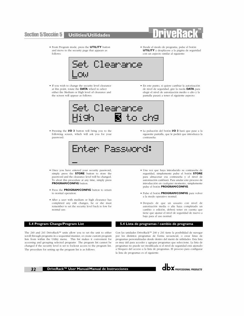
Utilities/Utilidades
®
32
Section 5/Sección 5 DriveRack™
®
DriveRack™ User Manual/Manual de Instrucciones
• From Program mode, press the UTILITY buttonand move to the security page that appears asfollows:
• If you wish to change the security level clearanceat this point, rotate the DATA wheel to selecteither the Medium or High level of clearance andthe screen will appear as follows:
• Pressing the I/O 3 button will bring you to thefollowing screen, which will ask you for yourpassword:
• Once you have entered your security password,simply press the STORE button to store thepassword and the clearance level will be changed.To abort this procedure at any time, simply pressPROGRAM/CONFIG button.
• Press the PROGRAM/CONFIG button to returnto normal operation.
• After a user with medium or high clearance hascompleted any edit changes, he or she mustremember to set the security level back to low fornormal use.
The 240 and 241 DriveRack™ units allow you to set the unit to eitherscroll through programs in a sequential manner, or create custom programlists from within the Utility menu. This list makes it convenient foraccessing and grouping selected programs The program list cannot bechanged if the security level is set to lockout access to the program list.
The procedure for setting up the program list is as follows.
• Desde el modo de programa, pulse el botónUTILITY y desplácese a la página de seguridadcon un aspecto similar al siguiente:
• En este punto, si quiere cambiar la autorizaciónde nivel de seguridad, gire la rueda DATA paraelegir el nivel de autorización medio o alto y lapantalla pasará a tener el siguiente aspecto:
• La pulsación del botón I/O 3 hará que pase a lasiguiente pantalla, que le pedirá que introduzca lacontraseña:
• Una vez que haya introducido su contraseña deseguridad, simplemente pulse el botón STOREpara almacenar esa contraseña y el nivel deautorización cambiará. Para anular este proceso deintroducción en cualquier momento, simplementepulse el botón PROGRAM/CONFIG.
• Pulse el botón PROGRAM/CONFIG para volvera la modo operativo normal.
• Después de que un usuario con nivel deautorización media o alta haya completado uncambio o edición, deberá tener en cuenta quetiene que ajustar el nivel de seguridad de nuevo abajo para el uso normal.
Con las unidades DriveRack™ 240 y 241 tiene la posibilidad de navegarpor los distintos programas de forma secuencial, o crear listas deprogramas personalizadas desde dentro del menú de utilidades. Esta listaes muy útil para acceder y agrupar programas que seleccione. La lista deprogramas no puede ser modificada si el nivel de seguridad está ajustadoa bloqueo del acceso a la lista de programas. El proceso para configurar
la lista de programas es el siguiente.
5.4 Program Change/Program List 5.4 Lista de programas / cambio de programa
Set ClearanceLow
Set ClearanceHigh 3 to chg
Enter Password:
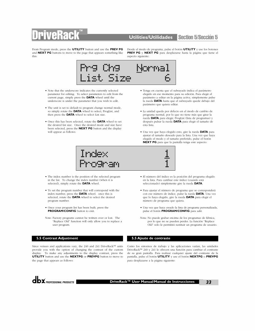
®
Utilities/Utilidades Section 5/Sección 5DriveRack™
33®
DriveRack™ User Manual/Manual de Instrucciones
From Program mode, press the UTILITY button and use the PREV PGand NEXT PG buttons to move to the page that appears something likethis:
• Note that the underscore indicates the currently selectedparameter for editing. To select parameters to edit from thecurrent page, simply press the DATA wheel until theunderscore is under the parameter that you wish to edit.
• The unit is set to default to program change normal mode,so simply rotate the DATA wheel to select; ProgList, andthen press the DATA wheel to select List size.
• Once this has been selected, rotate the DATA wheel to setthe desired list size. Once the desired mode and size havebeen selected, press the NEXT PG button and the displaywill appear as follows:
• The index number is the position of the selected programin the list. To change the index number (when it isselected), simply rotate the DATA wheel.
• To set the program number that will correspond with theindex number, press the DATA wheel. once this isselected, rotate the DATA wheel to select the desiredprogram number.
• Once your program list has been built, press thePROGRAM/CONFIG button to exit.
Note: Factory programs cannot be written over or lost. The“Replace Old” function will only allow you to replace auser program.
Since venues and applications vary, the 240 and 241 DriveRack™ unitsprovide you with the option of changing the contrast of the customdisplay. To make any adjustments to the display contrast, press theUTILITY button and use the NEXTPG or PREVPG button to move to
the page that appears as follows:
Desde el modo de programa, pulse el botón UTILITY y use los botonesPREV PG y NEXT PG para desplazarse hasta la página que tiene elaspecto siguiente:
• Tenga en cuenta que el subrayado indica el parámetroelegido en ese momento para su edición. Para elegir elparámetro a editar en la página activa, simplemente pulsela rueda DATA hasta que el subrayado quede debajo delparámetro que quiera editar.
• La unidad queda por defecto en el modo de cambio deprograma normal, por lo que no tiene más que girar larueda DATA para elegir; ProgList (lista de programas) ydespués pulsar la rueda DATA para elegir el tamaño deesta lista.
• Una vez que haya elegido esto, gire la rueda DATA paraajustar el tamaño deseado para la lista. Una vez que hayaelegido el modo y el tamaño preferido, pulse el botónNEXT PG para que la pantalla tenga este aspecto:
• El número del índice es la posición del programa elegidoen la lista. Para cambiar este índice (cuando estáseleccionado) simplemente gire la rueda DATA.
• Para ajustar el número de programa que se corresponderácon ese número de índice, pulse la rueda DATA. Una vezque lo haya elegido, gire la rueda DATA para elegir elnúmero de programa que quiera.
• Una vez que haya creado la lista de programa personalizada,pulse el botón PROGRAM/CONFIG para salir.
Nota: No puede grabar encima de los programas de fábrica,por lo que no se pueden perder. La función “ReplaceOld” solo le permitirá sustituir un programa de usuario.
Como los entornos de trabajo y las aplicaciones varían, las unidadesDriveRack™ 240 y 241 le ofrecen una función para cambiar el contrastede su gran pantalla. Para realizar cualquier ajuste del contraste de lapantalla, pulse el botón UTILITY y use el botón NEXTPG o PREVPGpara desplazarse a la página siguiente:
5.5 Contrast Adjustment 5.5 Ajsute de contraste
Prg Chg NormalList Size 6
Index 1Program 1
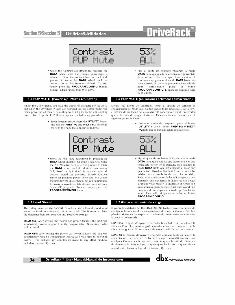
Utilities/Utilidades
®
34
Section 5/Sección 5 DriveRack™
®
• Select the Contrast adjustment by pressing theDATA wheel until the contrast percentage isselected. Once the contrast has been selected,proceed to rotate the DATA wheel until thedesired contrast has been established. To exit,simply press the PROGRAM/CONFIG button.Contrast adjust ranges from 0 to 100%.
Within the Utility menu, you have the option of changing the set up sothat when the DriveRack™ units are powered up, the output mutes willeither power up all muted, or as they were set prior to the unit shuttingdown. To change the PUP Mute setup, use the following procedure.
• From Program mode, press the UTILITY buttonand use the PREV PG and NEXT PG button tomove to the page that appears as follows:
• Select the PUP mute adjustment by pressing theDATA wheel until the PUP mute is selected. Oncethe PUP Mute has been selected, proceed to rotatethe DATA wheel until the desired mute setting(All, Saved or SyS Mute) is selected. All= Alloutputs muted on powerup, Saved= Outputsmutes on previous power down and SYS Mute=the unit powers up all muted, but can be unmutedby using a remote switch closure program as a“mute all” program. To exit, simply press thePROGRAM/CONFIG button.
The Utility menu of the 240/241 DriveRack also offers the option ofsetting the Load stored feature to either on or off. The following explainsthe difference between Load On and Load OFF settings.
LOAD On: After cycling the power (or power failure), the unit willautomatically load a program from the program table. No unstored editswill be saved.
LOAD OFF: After cycling the power (or power failure), the unit willautomatically reload a configuration exactly as it was prior to poweringdown. This includes any adjustments made to any effect modulesincluding: delays, EQs... etc.
• Elija el ajuste de contraste pulsando la ruedaDATA hasta que quede seleccionado el porcentajede contraste. Una vez que haya elegido elcontraste, vaya girando el mando DATA hasta quehaya ajustado el contraste que quiera. Para salir deaquí, simplemente pulse el botónPROGRAM/CONFIG. El ajuste de contraste varíade 0 a 100%.
Dentro del menú de utilidades, tiene la opción de cambiar laconfiguración de modo que cuando encienda las unidades DriveRack™,el sistema de anulación de las salidas esté conectado o quede en el valorque tenía antes de apagar el sistema. Para cambiar esta función, use elsiguiente procedimiento.
• Desde el modo de programa, pulse el botónUTILITY y use el botón PREV PG y NEXTPGhasta que la pantalla tenga este aspecto:
• Elija el ajuste de anulación PUP pulsando la ruedaDATA hasta que aparezca este ajuste. Una vez quetenga esta opción en la pantalla, vaya girando larueda DATA hasta que haya elegido el valor quequiera (All, Saved o Sys Mute). All = todas lassalidas quedan anuladas durante el encendido,Saved = las anulaciones de las salidas quedan conel mismo valor que tenían la última vez que apagóla unidad y Sys Mute = la unidad se enciende contodo anulado, pero puede ser activado usando unprograma de interruptor remoto de tipo “anulacióntotal”. Para salir, simplemente pulse el botónPROGRAM/CONFIG.
El menú de utilidades del DriveRack 240/241 también ofrece la opción deconfigurar la función de almacenamiento de carga a On o a Off. Lospárrafos siguientes le explican la diferencia entre tener esta funciónactivada o desactivada.
LOAD On: Después de apagar y encender la unidad (o de un fallo en laalimentación), el aparato cargará automáticamente un programa de latabla de programas. No será guardada ninguna edición no almacenada.
LOAD OFF: Después de apagar y encender la unidad (o de un fallo en laalimentación), el aparato volverá a cargar automáticamente unaconfiguración exacta a la que tenía antes de apagar la unidad o del cortede alimentación. Esto incluye cualquier ajuste hecho en cualquiera de los
módulos de efectos incluyendo: retardos, EQ, .... etc.
DriveRack™ User Manual/Manual de Instrucciones
5.6 PUP MUTE (Power Up Mutes On/Saved)
5.7 Load Stored
5.6 PUP MUTE (anulaciones activadas / almacenado)
5.7 Almacenamiento de carga
Contrast 53%PUP Mute ALL
Contrast 53%PUP Mute ALL
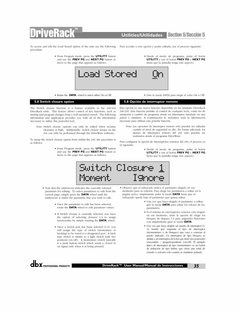
®
Utilities/Utilidades Section 5/Sección 5DriveRack™
35®
DriveRack™ User Manual/Manual de Instrucciones
To access and edit the Load Stored option of the unit, use the followingprocedure.
• From Program mode, press the UTILITY buttonand use the PREV PG and NEXT PG button tomove to the page that appears as follows:
• Rotate the DATA wheel to select either On or Off..
The Switch closure function is a feature available in the 240/241DriveRack units. This feature allows control of key functions, such asmuting and program changes from a wall mounted switch. The followinginformation and application provides you with all of the informationnecessary to utilize this powerful tool.
Note: Switch closure options can only be edited when securityclearance is high. Additionally, switch closure setups on the241 can only be performed through the DriveWare software.
To setup the switch closure option from within the 240, the procedure isas follows:
• From Program mode, press the UTILITY buttonand use the PREV PG and NEXT PG button tomove to the page that appears as follows:
• Note that the underscore indicates the currently selectedparameter for editing. To select parameters to edit from thecurrent page, simply press the DATA wheel until theunderscore is under the parameter that you wish to edit.
• Once the parameter to edit has been selected,rotate the DATA wheel to edit parameter values.
• If Switch closure is currently selected, you havethe option of selecting closures 1-4 to assignfunctionality by simply rotating the DATA wheel.
• Once a switch port has been selected (1-4), youwill assign the type of switch (momentary orlatching) to be wired to a designated port. A latchtype switch is similar to a light switch with twopositions (on/off). A momentary switch typicallyis a push button switch which sends a closed oron signal only when it is being pressed.
Para acceder a esta opción y poder editarla, use el proceso siguiente:
• Desde el modo de programa, pulse el botónUTILITY y use el botón PREV PG y NEXT PGhasta que la pantalla tenga este aspecto:
• Gire la rueda DATA para elegir el valor On u Off.
Esta opción es una nueva función disponible en las unidades DriveRack240/241. Esta función permite el control de cualquier tecla, como las deanulación y cambio de programa desde un interruptor instalado en unapared o similares. A continuación le incluimos toda la informaciónnecesaria para utilizar esta potente función.
Nota: Las opciones de interruptor remoto solo pueden ser editadascuando el nivel de seguridad es alto. De forma adicional, losajustes de interruptor remoto del 241 solo pueden serrealizados desde el programa DriveWare.
Para configurar la opción de interruptores remotos del 240, el proceso esel siguiente:
• Desde el modo de programa, pulse el botónUTILITY y use el botón PREV PG y NEXT PGhasta que la pantalla tenga este aspecto:
• Observe que el subrayado indica el parámetro elegido en esemomento para su edición. Para elegir los parámetros a editar en lapágina activa, simplemente pulse la rueda DATA hasta que elsubrayado quede bajo el parámetro que quiera editar.
• Una vez que haya elegido el parámetro a editar,gire la rueda DATA para editar los valores de losparámetros.
• Si el sistema de interruptores remotos está elegidoen ese momento, tiene la opción de elegir losbloques de disparo 1-4 para asignarles funcionescon simplemente girar la rueda DATA.
• Una vez que haya elegido un puerto de interruptor (1-4), tendrá que asignarle el tipo de interruptor(momentáneo o de bloqueo) que vaya a conectar alpuerto indicado. Un interruptor de tipo bloqueo essimilar a un interruptor de la luz que tiene dos posiciones(encendido / apagado)positions (on/off). El ejemplotípico de interruptor de tipo momentáneo es un botónde pulsación de tipo timbre que envía una señal de
cerrado o activado solo cuando se mantiene pulsado.
5.8 Switch closure option 5.8 Opción de interruptor remoto
Load Stored On
Switch Closure 1
Moment Ignore
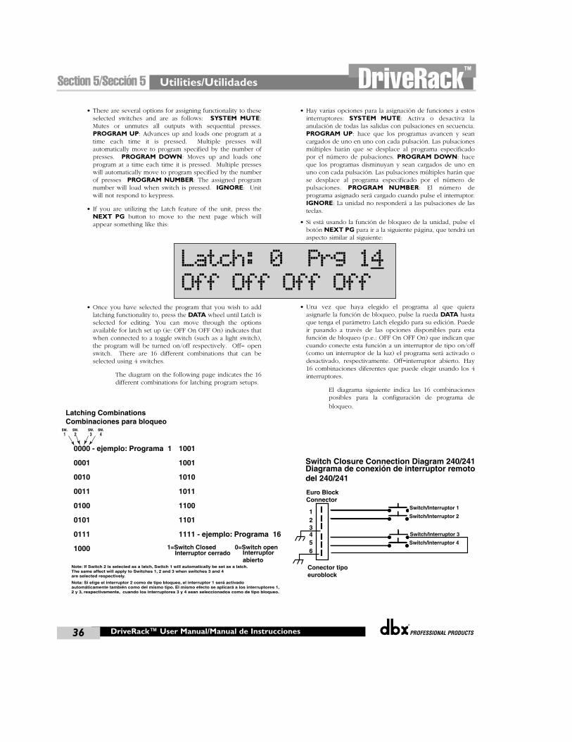
Utilities/Utilidades
®
36
Section 5/Sección 5 DriveRack™
®
DriveRack™ User Manual/Manual de Instrucciones
• There are several options for assigning functionality to theseselected switches and are as follows: SYSTEM MUTE:Mutes or unmutes all outputs with sequential presses.PROGRAM UP: Advances up and loads one program at atime each time it is pressed. Multiple presses willautomatically move to program specified by the number ofpresses. PROGRAM DOWN: Moves up and loads oneprogram at a time each time it is pressed. Multiple presseswill automatically move to program specified by the numberof presses PROGRAM NUMBER: The assigned programnumber will load when switch is pressed. IGNORE: Unitwill not respond to keypress.
• If you are utilizing the Latch feature of the unit, press theNEXT PG button to move to the next page which willappear something like this:
• Once you have selected the program that you wish to addlatching functionality to, press the DATA wheel until Latch isselected for editing. You can move through the optionsavailable for latch set up (ie: OFF On OFF On) indicates thatwhen connected to a toggle switch (such as a light switch),the program will be turned on/off respectively. Off= openswitch. There are 16 different combinations that can beselected using 4 switches.
The diagram on the following page indicates the 16different combinations for latching program setups.
• Hay varias opciones para la asignación de funciones a estosinterruptores: SYSTEM MUTE: Activa o desactiva laanulación de todas las salidas con pulsaciones en secuencia.PROGRAM UP: hace que los programas avancen y seancargados de uno en uno con cada pulsación. Las pulsacionesmúltiples harán que se desplace al programa especificadopor el número de pulsaciones. PROGRAM DOWN: haceque los programas disminuyan y sean cargados de uno enuno con cada pulsación. Las pulsaciones múltiples harán quese desplace al programa especificado por el número depulsaciones. PROGRAM NUMBER: El número deprograma asignado será cargado cuando pulse el interruptor.IGNORE: La unidad no responderá a las pulsaciones de lasteclas.
• Si está usando la función de bloqueo de la unidad, pulse elbotón NEXT PG para ir a la siguiente página, que tendrá unaspecto similar al siguiente:
• Una vez que haya elegido el programa al que quieraasignarle la función de bloqueo, pulse la rueda DATA hastaque tenga el parámetro Latch elegido para su edición. Puedeir pasando a través de las opciones disponibles para estafunción de bloqueo (p.e.: OFF On OFF On) que indican quecuando conecte esta función a un interruptor de tipo on/off(como un interruptor de la luz) el programa será activado odesactivado, respectivamente. Off=interruptor abierto. Hay16 combinaciones diferentes que puede elegir usando los 4interruptores.
El diagrama siguiente indica las 16 combinacionesposibles para la configuración de programa de
bloqueo.
Latch: 0 Prg 14
Off Off Off Off
Latching Combinations
0000 - ejemplo: Programa 1 1001
1=Switch Closed 0=Switch open
0001
sw.1
sw.2
sw.3
sw.4
1001
0010 1010
0011 1011
0100 1100
0101 1101
0111 1111 - ejemplo: Programa 16
1000
Note: If Switch 2 is selected as a latch, Switch 1 will automatically be set as a latch.The same affect will apply to Switches 1, 2 and 3 when switches 3 and 4 are selected respectively.
Combinaciones para bloqueo
Interruptor cerrado Interruptorabierto
Nota: Si elige el interruptor 2 como de tipo bloqueo, el interruptor 1 será activado automáticamente también como del mismo tipo. El mismo efecto se aplicará a los interruptores 1, 2 y 3, respectivamente, cuando los interruptores 3 y 4 sean seleccionados como de tipo bloqueo.
Euro BlockConnector
Switch Closure Connection Diagram 240/241
1Switch/Interruptor 1
Switch/Interruptor 223456
Switch/Interruptor 3
Switch/Interruptor 4
Diagrama de conexión de interruptor remoto del 240/241
Conector tipo euroblock
DriveWareGUI
GUI DriveWare
®
Section 6/Sección 6DriveRack™
GUI Install/Instalación GUI
®
38
Section 6/Sección 6 DriveRack™
DriveRack™ User Manual/Manual de Instrucciones
To make operation of the DriveWare™ units even more convenient, dbxprofessional products includes the DriveRack™ PC GUI software withevery unit shipped. The GUI interface will allow you to control allaspects of the DriveRack™ units.
The following section contains some basic information regarding theutilization of the DriveWare™ software including: install, systemrequirements, cable specifications and basic operation.
SYSTEM REQUIREMENTSMin. system- 166mhz PC processor - 16 bit color monitor - 32 megRAM - Windows™ 95 OS R2 or newer - Windows™ NT 4.0 or newer -Baud rate (fixed) 38.4 kbaudNote- COMM port setting must be consistent. This means that when theGUI is in use, any other device that uses the RS232 COMM port must beturned off.
INSTALL• Install the DriveRack™ GUI interface from either the dbx Professional
Products website at: www.dbxpro.com or from the CD ROM ontoyour your PC or laptop.
• Once the software is downloaded or CD is loaded, simply doubleclick on the file named: DriveRack™ setup.
• The application will proceed to ask you where you want theprogram installed.
• Once the software installation has been completed, it isrecommended that you restart your computer.
• Make all network device connections prior to running the GUIinterface.
The following information offers basic operation information of theDriveRack™ GUI interface
BASIC OPERATIONOnce the unit has been connected, boot up the GUI Interface bydouble-clicking on the application icon. When the program opens, thefirst view you will see will be the UNIT view if the unit is notconnected to the PC. This view has icon representations of the unitbeing used. Simply double-click on the unit to access and edit.
If the unit is connected to the PC, the program will boot up with ablock diagram of the unit. To edit modules, simply double-click on thedesired module block.
• To adjust the utility menu, Right-Click-hold on the top bar of thewindow to pull down the utility menu.
Para facilitar el funcionamiento con las unidades DriveRack™, dbxProfessional Products incluye con cada unidad un programa de softwareDriveRack™ PC GUI. El interface GUI le permitirá controlar todos losaspectos de las unidades DriveRack™.
Esta sección le ofrece información básica acerca del uso del programaDriveWare™ incluyendo: instalación, requisitos del sistema,especificaciones del cable y funcionamiento básico.
REQUISITOS DEL SISTEMASistema mínimo – Procesador PC 166 MHz – monitor color de 16 bits –32 MB de RAM – Windows™ 95 OS R2 o posterior – Windows™ NT 4.0o posterior – Velocidad en baudios (fija) 38.4 KbaudiosNota – La configuración del puerto COMM ha de ser constante. Estoquiere decir que cuando la GUI esté en uso, cualquier otra unidad queuse el puerto COMM RS232 deberá estar desactivada.
INSTALACION• Instale el interface DriveRack™ GUI o bien bajándoselo desde la
página web de dbx Professional Products en www.dbxpro.com ocon el CD ROM que incluimos en su PC o portátil.
• Una vez que haya descargado el software o haya introducido el CD,simplemente haga doble clic en el archivo llamado: DriveRack™setup.
• La aplicación le preguntará dónde quiere instalar el programa.
• Una vez completada la instalación del software, recomendamos quereinicie su ordenador.
• Haga todas las conexiones de la red antes de poner en marcha elinterface GUI.
En los párrafos siguientes le ofrecemos información básica acerca delfuncionamiento del interface DriveRack™ GUI.
FUNCIONAMIENTO BASICOUna vez que estén conectadas todas las unidades, ponga en marcha elinterface GUI haciendo doble clic en el icono de la aplicación. Cuandose abra el programa, la primera vista que aparecerá será la vista UNITsi la unidad no está conectada al PC. Esta vista tiene representacionesen forma de iconos de la unidad que esté usando. Simplemente hagadoble clic en la unidad a la que quiera acceder y editar.
Si la unidad está conectada a su ordenador, el programa arrancará conuna vista de diagrama de bloques de la unidad. Para editar los módulos,simplemente haga doble clic sobre el módulo que quiera editar.
• Para ajustar el menú de utilidades, haga clic con el botón derecho delratón y manténgalo pulsado sobre la barra superior de la ventanapara desplegar el menú de utilidades.
6.1 PC GUI Installation 6.1 Instalación del interface gráfico de usuario de PC
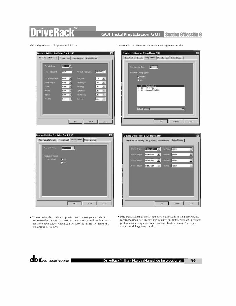
®
The utility menus will appear as follows:
• To customize the mode of operation to best suit your needs, it isrecommended that at this point, you set your desired preferences inthe preference folder, which can be accessed in the file menu andwill appear as follows:
Los menús de utilidades aparecerán del siguiente modo:
• Para personalizar el modo operativo y adecuarlo a sus necesidades,recomendamos que en este punto ajuste su preferencias en la carpetapreferences, a la que se puede acceder desde el menú File y queaparecerá del siguiente modo:
GUI Install/Instalación GUI Section 6/Sección 6DriveRack™
39DriveRack™ User Manual/Manual de Instrucciones
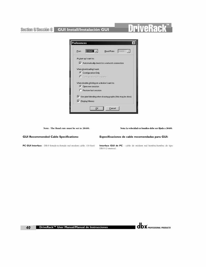
GUI Install/Instalación GUI
®
40
Section 6/Sección 6 DriveRack™
DriveRack™ User Manual/Manual de Instrucciones
Note: The Baud rate must be set to 38400.
GUI Recommended Cable Specifications:
PC GUI Interface - DB-9 female-to-female nul modem cable. (10 feet)
Nota: La velocidad en baudios debe ser fijada a 38400.
Especificaciones de cable recomendadas para GUI:
Interface GUI de PC - cable de módem nul hembra-hembra de tipoDB-9 (3 metros).

APPLICATION
GUIDE
GUÍA DE APLICACIÓN
®
Section 7/Sección 7DriveRack™
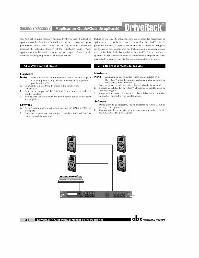
Application Guide/Guía de aplicación
®
42
Section 7/Sección 7 DriveRack™
This Application guide section is provided to offer suggested installation
applications of the DriveRack™ units that will allow you to optimize peak
performance of the units. Note that the six included applications
represent the extensive flexibility of the DriveRack™ units. These
applications can be used verbatim, or as sample reference guide
templates for designing countless audio applications.
HardwareNote Make sure that all outputs are muted on the DriveRack™ prior
to adding power to any devices in the signal path (pre and post DriveRack™).
1. Connect the outputs from the mixer to the inputs of theDriveRack™.
2. Connect the outputs of the DriveRack™ and run to the selectedspeaker amplifier.
3. Making sure that all outputs are muted, apply power to the mixerand amplifiers.
Software1. From Program mode, select factory program #21 (2Way w/GEQ) as
a template.2. Once the program has been chosen, press the PROGRAM/CONFIG
button to load the program.
Incluimos esta guía de aplicación para que conozca las sugerencias de
aplicaciones de instalación para las unidades DriveRack™ que le
permitirán optimizar a tope el rendimiento de las unidades. Tenga en
cuenta que las siete aplicaciones que incluimos aquí quieren representar
toda la flexibilidad de las unidades DriveRack™. Puede usar estos
ejemplos de aplicaciones tal como los describimos o simplemente como
una guía de referencia para diseñar sus propias aplicaciones audio.
HardwareNota Asegúrese de que todas las salidas están anuladas en el
DriveRack™ antes de encender cualquier unidad de la ruta deseñal (pre y post DriveRack™).
1. Conecte las salidas del mezclador a las entradas del DriveRack™.2. Conecte las salidas del DriveRack™ al sistema de amplificación de
altavoces elegido.3. Asegurándose antes de que todas las salidas están anuladas,
encienda el mezclador y los amplificadores.
Software1. Desde el modo de Programa, elija el programa de fábrica 21 (2Way
w/GEQ) como plantilla.2. Una vez que haya escogido el programa anterior, pulse el botón
PROGRAM/CONFIG para cargarlo.
DriveRack™ User Manual/Manual de Instrucciones
7.1 2-Way Front of House 7.1 2-Recintos directos de dos vías
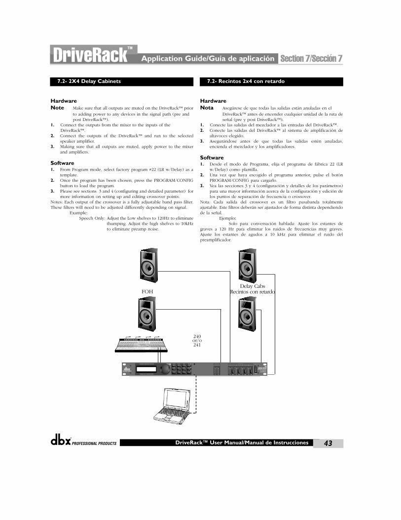
®
HardwareNote Make sure that all outputs are muted on the DriveRack™ prior
to adding power to any devices in the signal path (pre and post DriveRack™).
1. Connect the outputs from the mixer to the inputs of theDriveRack™.
2. Connect the outputs of the DriveRack™ and run to the selectedspeaker amplifier.
3. Making sure that all outputs are muted, apply power to the mixerand amplifiers.
Software1. From Program mode, select factory program #22 (LR w/Delay) as a
template.2. Once the program has been chosen, press the PROGRAM/CONFIG
button to load the program.3. Please see sections 3 and 4 (configuring and detailed parameter) for
more information on setting up and editing crossover points.Notes: Each output of the crossover is a fully adjustable band pass filter.These filters will need to be adjusted differently depending on signal.
Example:Speech Only: Adjust the Low shelves to 120Hz to eliminate
thumping. Adjust the high shelves to 10kHzto eliminate preamp noise.
HardwareNota Asegúrese de que todas las salidas están anuladas en el
DriveRack™ antes de encender cualquier unidad de la ruta deseñal (pre y post DriveRack™).
1. Conecte las salidas del mezclador a las entradas del DriveRack™.2. Conecte las salidas del DriveRack™ al sistema de amplificación de
altavoces elegido.3. Asegurándose antes de que todas las salidas estén anuladas,
encienda el mezclador y los amplificadores.
Software1. Desde el modo de Programa, elija el programa de fábrica 22 (LR
w/Delay) como plantilla.2. Una vez que haya escogido el programa anterior, pulse el botón
PROGRAM/CONFIG para cargarlo.3. Vea las secciones 3 y 4 (configuración y detalles de los parámetros)
para una mayor información acerca de la configuración y edición delos puntos de separación de frecuencia o crossover.
Nota: Cada salida del crossover es un filtro pasabanda totalmenteajustable. Este filtros deberán ser ajustados de forma distinta dependiendode la señal.
Ejemplo:Solo para conversación hablada: Ajuste los estantes de
graves a 120 Hz para eliminar los ruidos de frecuencias muy graves.Ajuste los estantes de agudos a 10 kHz para eliminar el ruido delpreamplificador.
Application Guide/Guía de aplicación Section 7/Sección 7DriveRack™
43DriveRack™ User Manual/Manual de Instrucciones
7.2- 2X4 Delay Cabinets 7.2- Recintos 2x4 con retardo
FOHDelay Cabs
Recintos con retardo
240or/o241
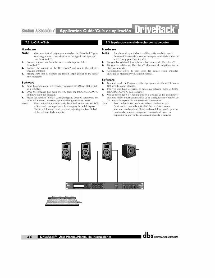
Application Guide/Guía de aplicación
®
44
Section 7/Sección 7 DriveRack™
HardwareNote Make sure that all outputs are muted on the DriveRack™ prior
to adding power to any devices in the signal path (pre and post DriveRack™).
1. Connect the outputs from the mixer to the inputs of theDriveRack™.
2. Connect the outputs of the DriveRack™ and run to the selectedspeaker amplifier.
3. Making sure that all outputs are muted, apply power to the mixerand amplifiers.
Software1. From Program mode, select factory program #23 (Mono LCR w/Sub)
as a template.2. Once the program has been chosen, press the PROGRAM/CONFIG
button to load the program.3. Please see sections 3 and 4 (configuring and detailed parameter) for
more information on setting up and editing crossover points.Notes: This configuration can be easily be edited to function in a LCR
w/Surround rear application by changing the sub lowpass filter to a full range band pass and adjusting the Low Rolloff of the Left and Right outputs.
HardwareNota Asegúrese de que todas las salidas están anuladas en el
DriveRack™ antes de encender cualquier unidad de la ruta deseñal (pre y post DriveRack™).
1. Conecte las salidas del mezclador a las entradas del DriveRack™.2. Conecte las salidas del DriveRack™ al sistema de amplificación de
altavoces elegido.3. Asegurándose antes de que todas las salidas estén anuladas,
encienda el mezclador y los amplificadores.
Software1. Desde el modo de Programa, elija el programa de fábrica 23 (Mono
LCR w/Sub) como plantilla.2. Una vez que haya escogido el programa anterior, pulse el botón
PROGRAM/CONFIG para cargarlo.3. Vea las secciones 3 y 4 (configuración y detalles de los parámetros)
para una mayor información acerca de la configuración y edición delos puntos de separación de frecuencia o crossover.
Nota: Esta configuración puede ser editada fácilmente para funcionar en una aplicación I+C+D con altavoz trasero surround cambiando el filtro pasabajo del subwoofer por un pasabanda de rango completo y ajustando el punto de supresión de graves de las salidas izquierda y derecha.
DriveRack™ User Manual/Manual de Instrucciones
7.3 L-C-R w/Sub 7.3 Izquierdo-central-derecho con subwoofer
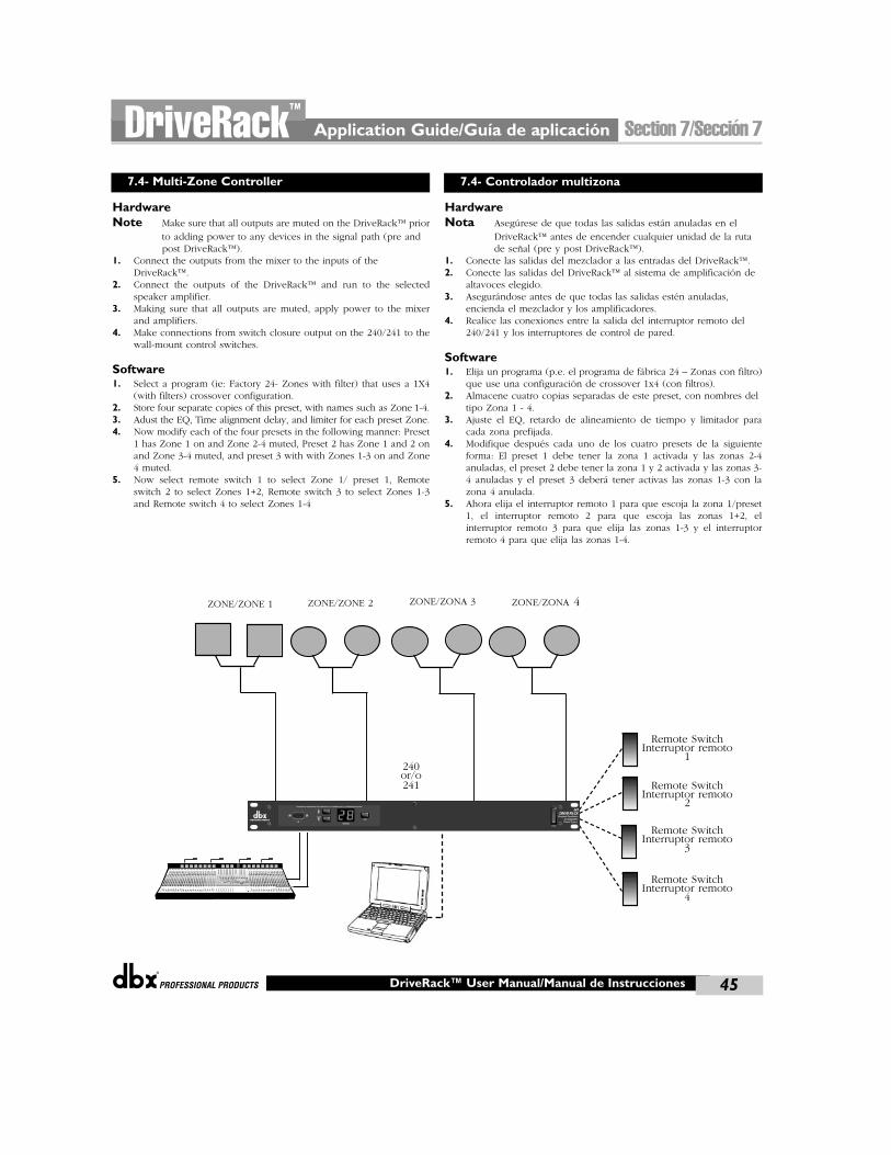
®
Application Guide/Guía de aplicación Section 7/Sección 7DriveRack™
45DriveRack™ User Manual/Manual de Instrucciones
ZONE/ZONE 1 ZONE/ZONE 2 ZONE/ZONA 3 ZONE/ZONA 4
Remote SwitchInterruptor remoto
1240or/o241
7.4- Multi-Zone Controller
HardwareNote Make sure that all outputs are muted on the DriveRack™ prior
to adding power to any devices in the signal path (pre and post DriveRack™).
1. Connect the outputs from the mixer to the inputs of theDriveRack™.
2. Connect the outputs of the DriveRack™ and run to the selectedspeaker amplifier.
3. Making sure that all outputs are muted, apply power to the mixerand amplifiers.
4. Make connections from switch closure output on the 240/241 to thewall-mount control switches.
Software1. Select a program (ie: Factory 24- Zones with filter) that uses a 1X4
(with filters) crossover configuration.2. Store four separate copies of this preset, with names such as Zone 1-4.3. Adust the EQ, Time alignment delay, and limiter for each preset Zone.4. Now modify each of the four presets in the following manner: Preset
1 has Zone 1 on and Zone 2-4 muted, Preset 2 has Zone 1 and 2 onand Zone 3-4 muted, and preset 3 with with Zones 1-3 on and Zone4 muted.
5. Now select remote switch 1 to select Zone 1/ preset 1, Remoteswitch 2 to select Zones 1+2, Remote switch 3 to select Zones 1-3and Remote switch 4 to select Zones 1-4
HardwareNota Asegúrese de que todas las salidas están anuladas en el
DriveRack™ antes de encender cualquier unidad de la ruta de señal (pre y post DriveRack™).
1. Conecte las salidas del mezclador a las entradas del DriveRack™.2. Conecte las salidas del DriveRack™ al sistema de amplificación de
altavoces elegido.3. Asegurándose antes de que todas las salidas estén anuladas,
encienda el mezclador y los amplificadores.4. Realice las conexiones entre la salida del interruptor remoto del
240/241 y los interruptores de control de pared.
Software1. Elija un programa (p.e. el programa de fábrica 24 – Zonas con filtro)
que use una configuración de crossover 1x4 (con filtros).2. Almacene cuatro copias separadas de este preset, con nombres del
tipo Zona 1 - 4.3. Ajuste el EQ, retardo de alineamiento de tiempo y limitador para
cada zona prefijada.4. Modifique después cada uno de los cuatro presets de la siguiente
forma: El preset 1 debe tener la zona 1 activada y las zonas 2-4anuladas, el preset 2 debe tener la zona 1 y 2 activada y las zonas 3-4 anuladas y el preset 3 deberá tener activas las zonas 1-3 con lazona 4 anulada.
5. Ahora elija el interruptor remoto 1 para que escoja la zona 1/preset1, el interruptor remoto 2 para que escoja las zonas 1+2, elinterruptor remoto 3 para que elija las zonas 1-3 y el interruptorremoto 4 para que elija las zonas 1-4.
7.4- Controlador multizona
Remote SwitchInterruptor remoto
2
Remote SwitchInterruptor remoto
3
Remote SwitchInterruptor remoto
4
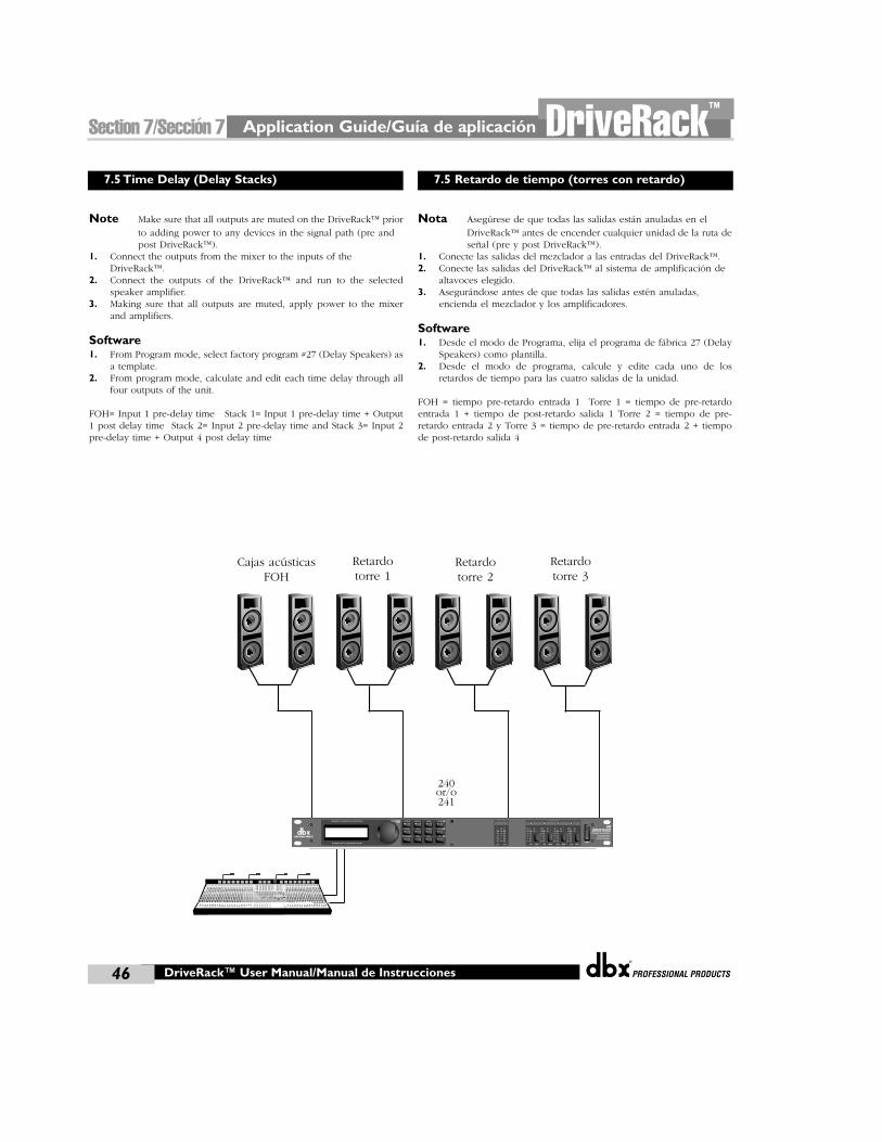
Application Guide/Guía de aplicación
®
46
Section 7/Sección 7 DriveRack™
DriveRack™ User Manual/Manual de Instrucciones
7.5 Time Delay (Delay Stacks) 7.5 Retardo de tiempo (torres con retardo)
Cajas acústicas FOH
Retardotorre 1
Retardotorre 2
Retardotorre 3
240or/o241
Note Make sure that all outputs are muted on the DriveRack™ priorto adding power to any devices in the signal path (pre and post DriveRack™).
1. Connect the outputs from the mixer to the inputs of theDriveRack™.
2. Connect the outputs of the DriveRack™ and run to the selectedspeaker amplifier.
3. Making sure that all outputs are muted, apply power to the mixerand amplifiers.
Software1. From Program mode, select factory program #27 (Delay Speakers) as
a template.2. From program mode, calculate and edit each time delay through all
four outputs of the unit.
FOH= Input 1 pre-delay time Stack 1= Input 1 pre-delay time + Output1 post delay time Stack 2= Input 2 pre-delay time and Stack 3= Input 2pre-delay time + Output 4 post delay time
Nota Asegúrese de que todas las salidas están anuladas en el DriveRack™ antes de encender cualquier unidad de la ruta deseñal (pre y post DriveRack™).
1. Conecte las salidas del mezclador a las entradas del DriveRack™.2. Conecte las salidas del DriveRack™ al sistema de amplificación de
altavoces elegido.3. Asegurándose antes de que todas las salidas estén anuladas,
encienda el mezclador y los amplificadores.
Software1. Desde el modo de Programa, elija el programa de fábrica 27 (Delay
Speakers) como plantilla.2. Desde el modo de programa, calcule y edite cada uno de los
retardos de tiempo para las cuatro salidas de la unidad.
FOH = tiempo pre-retardo entrada 1 Torre 1 = tiempo de pre-retardoentrada 1 + tiempo de post-retardo salida 1 Torre 2 = tiempo de pre-retardo entrada 2 y Torre 3 = tiempo de pre-retardo entrada 2 + tiempode post-retardo salida 4
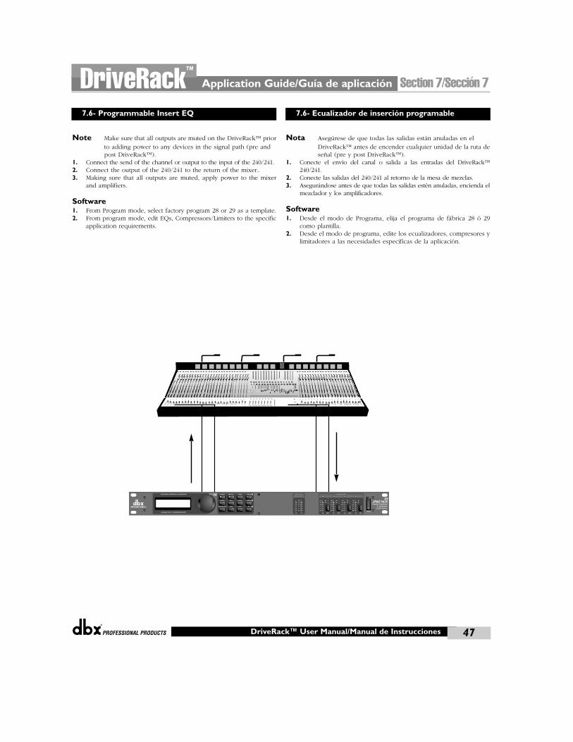
®
Application Guide/Guía de aplicación Section 7/Sección 7DriveRack™
47DriveRack™ User Manual/Manual de Instrucciones
7.6- Programmable Insert EQ 7.6- Ecualizador de inserción programable
Note Make sure that all outputs are muted on the DriveRack™ priorto adding power to any devices in the signal path (pre and post DriveRack™).
1. Connect the send of the channel or output to the input of the 240/241. 2. Connect the output of the 240/241 to the return of the mixer..3. Making sure that all outputs are muted, apply power to the mixer
and amplifiers.
Software1. From Program mode, select factory program 28 or 29 as a template.2. From program mode, edit EQs, Compressors/Limiters to the specific
application requirements.
Nota Asegúrese de que todas las salidas están anuladas en el DriveRack™ antes de encender cualquier unidad de la ruta deseñal (pre y post DriveRack™).
1. Conecte el envío del canal o salida a las entradas del DriveRack™240/241.
2. Conecte las salidas del 240/241 al retorno de la mesa de mezclas.3. Asegurándose antes de que todas las salidas estén anuladas, encienda el
mezclador y los amplificadores.
Software1. Desde el modo de Programa, elija el programa de fábrica 28 ó 29
como plantilla.2. Desde el modo de programa, edite los ecualizadores, compresores y
limitadores a las necesidades específicas de la aplicación.
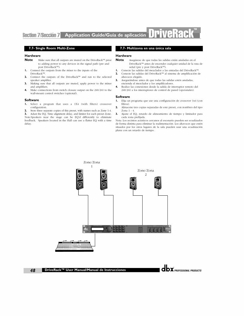
Zone/Zona1
Zone/Zona2
Application Guide/Guía de aplicaciónSection 7/Sección 7 DriveRack™
®
48 DriveRack™ User Manual/Manual de Instrucciones
7.7- Single Room Multi-Zone 7.7- Multizona en una única sala
HardwareNote Make sure that all outputs are muted on the DriveRack™ prior
to adding power to any devices in the signal path (pre and post DriveRack™).
1. Connect the outputs from the mixer to the inputs of theDriveRack™.
2. Connect the outputs of the DriveRack™ and run to the selectedspeaker amplifier.
3. Making sure that all outputs are muted, apply power to the mixerand amplifiers.
4. Make connections from switch closure output on the 240/241 to thewall-mount control switches (optional).
Software1. Select a program that uses a 1X4 (with filters) crossover
configuration.2. Store three separate copies of this preset, with names such as Zone 1-4.3. Adust the EQ, Time alignment delay, and limiter for each preset Zone.Note:Speakers near the stage can be EQ’d differently to eliminatefeedback. Speakers located in the Hall can use a flatter EQ with a timedelay.
HardwareNota Asegúrese de que todas las salidas están anuladas en el
DriveRack™ antes de encender cualquier unidad de la ruta deseñal (pre y post DriveRack™).
1. Conecte las salidas del mezclador a las entradas del DriveRack™.2. Conecte las salidas del DriveRack™ al sistema de amplificación de
altavoces elegido.3. Asegurándose antes de que todas las salidas estén anuladas,
encienda el mezclador y los amplificadores.4. Realice las conexiones desde la salida de interruptor remoto del
240/241 a los interruptores de control de pared (opcionales).
Software1. Elija un programa que use una configuración de crossover 1x4 (con
filtros).2. Almacene tres copias separadas de este preset, con nombres del tipo
Zona 1 - 4.3. Ajuste el EQ, retardo de alineamiento de tiempo y limitador para
cada zona prefijada.Nota: Los recintos acústicos cercanos al escenario pueden ser ecualizadosde forma distinta para eliminar la realimentación. Los altavoces que esténsituados por los otros lugares de la sala pueden usar una ecualizaciónplana con un retardo de tiempo.
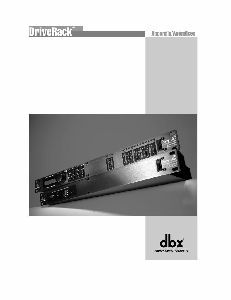
®
Appendix/ApéndicesDriveRack™
®
DriveRack™ User Manual/Manual de Instrucciones50
Appendix A/Apéndices A DriveRack™
In the event that a reset is required, the 240/241 DriveRack™ units offer youthe option of performing a “Soft” or “Hard” reset. The Soft Reset resets alloperating parameters except user programs. The Hard Reset Procedure willreset all programmable information back to the factory defaults.
240 Factory ("Hard") Reset• Press and Hold the STORE button on power-up until the following
message appears: "! HARD RESET?"
• Pressing the PREV PAGE button will start a Factory Reset (All UserPrograms will become copies of the Factory Programs, all Utilitysettings will be defaulted, and all Security settings will be defaulted)
Pressing the PROGRAM button will abort the Factory Reset sequenceand the unit will reset normally.
240 Factory ("Soft") Reset.Press and Hold the POST-EQ button at power-up until the followingmessage appears:
"! SOFT RESET?"
• Pressing the PREVPAGE button will start a System Reset (All Utilitysettings will be defaulted.)
• Pressing the PROGRAM button will abort the System Reset sequenceand the unit will reset normally.
241 Factory ("Hard") Reset• Press and hold the PROGRAM DOWN button on power-up until
the following message appears in the 7-Seg Display: "HD"
• Pressing the PROGRAM DOWN button will start a Factory Reset(All User Programs will become copies of the Factory Programs, all Utilitysettings will be defaulted, and all Security settings will be defaulted)
Pressing any other button will abort the Factory Reset sequence and theunit will reset normally.
241 Factory ("Soft") Reset.• Press and Hold the PROGRAM UP button on power-up until the
following message appears in the 7-Seg Display: "ST "
• Pressing the PROGRAM UP button will start a System Reset (AllUtility settings will be defaulted.)
Pressing any other button will abort the System Reset sequence and theunit will reset normally.
The DriveRack™ units offer several “Quick Key” options for initialpower up and are as follow:
240 Power-Up Output MutePress and hold any of the mute buttons at power-up. All of the outputswill be muted when the program loads.
240 Change Initial Program NumberPress and hold PROGRAM button at power-up until the followingmessage appears:
Chg Restart Prog Number
Press the PROGRAM button again when the selection is complete.Normal resetting will continue.
241 Power Up Quick Key options
PROGRAM CHANGE - Press and hold LOAD button on power-up:goes to program power up change mode.FLASH SCREEN - Press and hold LOAD and UP buttons on power up:goes to flash screen.
Para el caso de que sea necesaria una reinicialización, las unidadesDriveRack™ 240/241 le ofrecen la posibilidad de realizar una reinicialización“suave” o “dura”. La reinicialización suave restaura todos los datos excepto losprogramas de usuario. El proceso de reinicialización dura restaurará todos losdatos programables de nuevo a los valores que vienen de fábrica por defecto.
Reinicialización (“dura”) a valores de fábrica del 240• Mantenga pulsado el botón STORE mientras enciende la unidad
hasta que aparezca el siguiente mensaje:"! HARD RESET?"
• Al pulsar el botón PREV PAGE iniciará un reset a los valores de fábrica(todos los programas de usuario se convertirán en copias de los programasde fábrica, todos lo ajustes de las utilidades pasarán a sus valores pordefecto y todos los ajustes de seguridad pasarán a sus valores por defecto).
La pulsación del botón PROGRAMcancelará la secuencia dereinicialización y hará que la unidad se reinicie con normalidad.
Reinicialización (“blanda”) a valores de fábrica del 240Mantenga pulsado el botón POST-EQ durante el encendido hasta queaparezca el siguiente mensaje:
"! SOFT RESET?"
• Al pulsar el botón PREVPAGE se producirá una reinicialización del sistema(todos los valores de las utilidades pasarán a sus valores por defecto).
• La pulsación del botón PROGRAM cancelará la secuencia de reinicia-lización del sistema y hará que la unidad se reinicie con normalidad.
Reinicialización (“dura”) a valores de fábrica del 241• Mantenga pulsado el botón PROGRAM UP al encender la unidad
hasta que aparezca el siguiente mensaje en la pantalla de 7 segmentos:"HD"
• Cuando pulse el botón PROGRAM UP iniciará un reset a los valores defábrica (todos los programas de usuario se convertirán en copias de losprogramas de fábrica, todos los ajustes de las utilidades pasarán a sus valorespor defecto y todos los ajustes de seguridad pasarán a sus valores por defecto).
La pulsación de cualquier otro botón cancelará la secuencia dereinicialización y hará que la unidad se reinicie con normalidad.
Reinicialización (“blanda”) a valores de fábrica del 241• Mantenga pulsado el botón PROGRAM UP durante el encendido hasta
que aparezca el siguiente mensaje en la pantalla de 7 segmentos: "ST "
• Al pulsar el botón PROGRAM UP se producirá una reinicialización desistema (todos los valores de las utilidades pasarán a sus valores por defecto).
La pulsación de cualquier otro botón cancelará la secuencia dereinicialización de sistema y hará que la unidad se reinicie con normalidad.
Las unidades DriveRack™ ofrecen varias opciones de “teclas rápidas”que actuarán en el encendido inicial; son las siguientes:
Anulación de salida durante el encendido del 240Mantenga pulsado cualquiera de los botones de anulación durante elencendido. Todas las salidas estarán anuladas cuando cargue el programa.
Cambio de número de programa inicial del 240Mantenga pulsado PROGRAM durante el encendido hasta queaparezca el siguiente mensaje:
Chg Restart Prog Number
Pulse de nuevo el botón PROGRAM cuando haya terminado laselección. La reinicialización normal continuará.
Opciones de teclas rápidas en el encendido del 241
CAMBIO DE PROGRAMA - Mantenga pulsado el botón LOAD durante elencendido; esto hace que vaya al modo de cambio de programa en el encendido.
PANTALLA FLASH - Mantenga pulsados los botones LOAD y UPdurante el encendido; esto hace que vaya a la pantalla flash.
A.1 Factory Reset
A.2 Power Up Quick Key Options
A.1 Reset a valores de fábrica
A.2 Opciones de teclas rápidas en el encendido
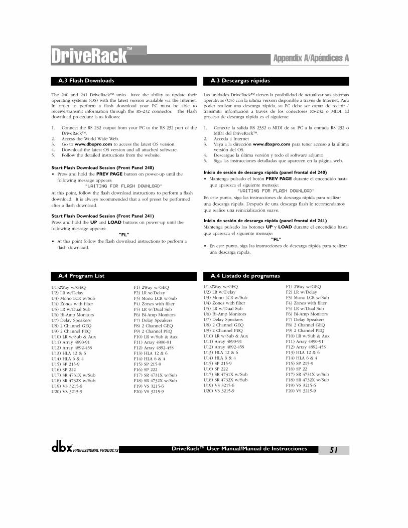
®
The 240 and 241 DriveRack™ units have the ability to update theiroperating systems (OS) with the latest version available via the Internet.In order to perform a flash download your PC must be able toreceive/transmit information through the RS-232 connector. The Flashdownload procedure is as follows:
1. Connect the RS 232 output from your PC to the RS 232 port of theDriveRack™.
2. Access the World Wide Web.3. Go to www.dbxpro.com to access the latest OS version.4. Download the latest OS version and all attached software.5. Follow the detailed instructions from the website.
Start Flash Download Session (Front Panel 240)• Press and hold the PREV PAGE button on power-up until the
following message appears:
"WAITING FOR FLASH DOWNLOAD"
At this point, follow the flash download instructions to perform a flash
download. It is always recommended that a sof preset be performed
after a flash download.
Start Flash Download Session (Front Panel 241)Press and hold the UP and LOAD buttons on power-up until the
following message appears:
"FL"• At this point follow the flash download instructions to perform a
flash download.
U1)2Way w/GEQ F1) 2Way w/GEQU2) LR w/Delay F2) LR w/DelayU3) Mono LCR w/Sub F3) Mono LCR w/SubU4) Zones with filter F4) Zones with filterU5) LR w/Dual Sub F5) LR w/Dual SubU6) Bi-Amp Monitors F6) Bi-Amp MonitorsU7) Delay Speakers F7) Delay SpeakersU8) 2 Channel GEQ F8) 2 Channel GEQU9) 2 Channel PEQ F9) 2 Channel PEQU10) LR w/Sub & Aux F10) LR w/Sub & AuxU11) Array 4890-91 F11) Array 4890-91U12) Array 4892-45S F12) Array 4892-45SU13) HLA 12 & 6 F13) HLA 12 & 6U14) HLA 6 & 4 F14) HLA 6 & 4U15) SP 215-9 F15) SP 215-9U16) SP 222 F16) SP 222U17) SR 4731X w/Sub F17) SR 4731X w/SubU18) SR 4732X w/Sub F18) SR 4732X w/SubU19) VS 3215-6 F19) VS 3215-6U20) VS 3215-9 F20) VS 3215-9
Las unidades DriveRack™ tienen la posibilidad de actualizar sus sistemasoperativos (OS) con la última versión disponible a través de Internet. Parapoder realizar una descarga rápida, su PC debe ser capaz de recibir /transmitir información a través de los conectores RS-232 o MIDI. Elproceso de descarga rápida es el siguiente:
1. Conecte la salida RS 2332 o MIDI de su PC a la entrada RS 232 oMIDI del DriveRack™.
2. Acceda a Internet3. Vaya a la dirección www.dbxpro.com para tener acceso a la última
versión del OS.4. Descargue la última versión y todo el software adjunto.5. Siga las instrucciones detalladas que aparecen en la página web.
Inicio de sesión de descarga rápida (panel frontal del 240)• Mantenga pulsado el botón PREV PAGE durante el encendido hasta
que aparezca el siguiente mensaje:
"WAITING FOR FLASH DOWNLOAD"
En este punto, siga las instrucciones de descarga rápida para realizar
una descarga rápida. Después de una descarga flash le recomendamos
que realice una reinicialización suave.
Inicio de sesión de descarga rápida (panel frontal del 241)Mantenga pulsado los botones UP y LOAD durante el encendido hasta
que aparezca el siguiente mensaje:
"FL"• En este punto, siga las instrucciones de descarga rápida para realizar
una descarga rápida.
U1)2Way w/GEQ F1) 2Way w/GEQU2) LR w/Delay F2) LR w/DelayU3) Mono LCR w/Sub F3) Mono LCR w/SubU4) Zones with filter F4) Zones with filterU5) LR w/Dual Sub F5) LR w/Dual SubU6) Bi-Amp Monitors F6) Bi-Amp MonitorsU7) Delay Speakers F7) Delay SpeakersU8) 2 Channel GEQ F8) 2 Channel GEQU9) 2 Channel PEQ F9) 2 Channel PEQU10) LR w/Sub & Aux F10) LR w/Sub & AuxU11) Array 4890-91 F11) Array 4890-91U12) Array 4892-45S F12) Array 4892-45SU13) HLA 12 & 6 F13) HLA 12 & 6U14) HLA 6 & 4 F14) HLA 6 & 4U15) SP 215-9 F15) SP 215-9U16) SP 222 F16) SP 22U17) SR 4731X w/Sub F17) SR 4731X w/SubU18) SR 4732X w/Sub F18) SR 4732X w/SubU19) VS 3215-6 F19) VS 3215-6U20) VS 3215-9 F20) VS 3215-9
Appendix A/Apéndices ADriveRack™
DriveRack™ User Manual/Manual de Instrucciones 51
A.3 Flash Downloads
A.4 Program List
A.3 Descargas rápidas
A.4 Listado de programas
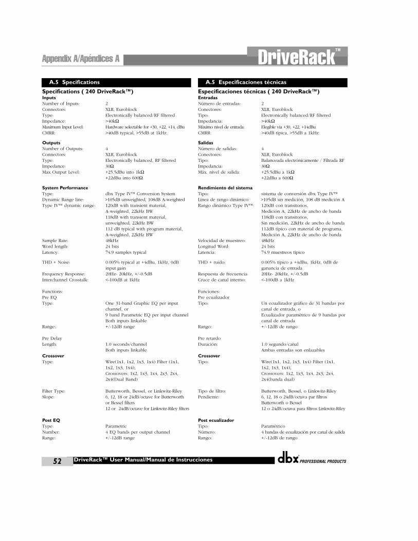
®
DriveRack™ User Manual/Manual de Instrucciones52
Appendix A/Apéndices A DriveRack™
Specifications ( 240 DriveRack™)InputsNumber of Inputs: 2 Connectors: XLR, EuroblockType: Electronically balanced/RF filteredImpedance: >40kΩMaximum Input Level: Hardware selectable for +30, +22, +14, dBuCMRR: >40dB typical, >55dB at 1kHz
OutputsNumber of Outputs: 4Connectors: XLR, EuroblockType: Electronically balanced, RF filteredImpedance: 30ΩMax Output Level: +25.5dBu into 1kΩ
+22dBu into 600Ω
System PerformanceType: dbx Type IV™ Conversion SystemDynamic Range line: >105dB unweighted, 108dB A-weightedType IV™ dynamic range: 120dB with transient material,
A-weighted, 22kHz BW118dB with transient material,unweighted, 22kHz BW112 dB typical with program material,A-weighted, 22kHz BW
Sample Rate: 48kHzWord length: 24 bitsLatency: 74.9 samples typical
THD + Noise: 0.005% typical at +4dBu, 1kHz, 0dB input gain
Frequency Response: 20Hz- 20kHz, +/-0.5dBInterchannel Crosstalk: <-100dB at 1kHz
Functions:Pre EQType: One 31-band Graphic EQ per input
channel, or9 band Parametric EQ per input channelBoth inputs linkable
Range: +/-12dB range
Pre DelayLength: 1.0 seconds/channel
Both inputs linkableCrossoverType: Wire(1x1, 1x2, 1x3, 1x4) Filter (1x1,
1x2, 1x3, 1x4),Crossovers: 1x2, 1x3, 1x4, 2x3, 2x4, 2x4(Dual Band)
Filter Type: Butterworth, Bessel, or Linkwitz-RileySlope: 6, 12, 18 or 24dB/octave for Butterworth
or Bessel filters12 or 24dB/octave for Linkwitz-Riley filters
Post EQType: ParametricNumber: 4 EQ bands per output channelRange: +/-12dB range
Especificaciones técnicas ( 240 DriveRack™)EntradasNúmero de entradas: 2 Conectores: XLR, EuroblockTipo: Electronically balanced/RF filteredImpedancia: >40kΩMáximo nivel de entrada: Elegible vía +30, +22, +14dBuCMRR: >40dB típica, >55dB a 1kHz
SalidasNúmero de salidas: 4Conectores: XLR, EuroblockTipo: Balanceada electrónicamente / Filtrada RFImpedancia: 30ΩMáx. nivel de salida: +25.5dBu a 1kΩ
+22dBu a 600Ω
Rendimiento del sistemaTipo: sistema de conversión dbx Type IV™ Línea de rango dinámico: >105dB sin medición, 108 dB medición ARango dinámico Type IV™: 120dB con transitorios,
Medición A, 22kHz de ancho de banda118dB con transitorios,Sin medición, 22kHz de ancho de banda112dB típico con material de programa,Medición A, 22kHz de ancho de banda
Velocidad de muestreo: 48kHzLongitud Word: 24 bitsLatencia: 74.9 muestreos típico
THD + ruido: 0.005% típico a +4dBu, 1kHz, 0dB de ganancia de entrada
Respuesta de frecuencia: 20Hz- 20kHz, +/-0.5dBCruce de canal interno: <-100dB a 1kHz
Funciones:Pre ecualizadorTipo: Un ecualizador gráfico de 31 bandas por
canal de entrada, oEcualizador paramétrico de 9 bandas porcanal de entrada
Rango: +/-12dB de rango
Pre retardoDuración: 1.0 segundo/canal
Ambas entradas son enlazablesCrossoverTipo: Wire(1x1, 1x2, 1x3, 1x4) Filter (1x1,
1x2, 1x3, 1x4),Crossovers: 1x2, 1x3, 1x4, 2x3, 2x4, 2x4(banda dual)
Tipo de filtro: Butterworth, Bessel, o Linkwitz-RileyPendiente: 6, 12, 18 o 24dB/octava par filtros
Butterworth o Bessel 12 o 24dB/octava para filtros Linkwitz-Riley
Post ecualizadorTipo: ParamétricoNúmero: 4 bandas de ecualización por canal de salidaRango: +/-12dB de rango
A.5 Specifications A.5 Especificaciones técnicas
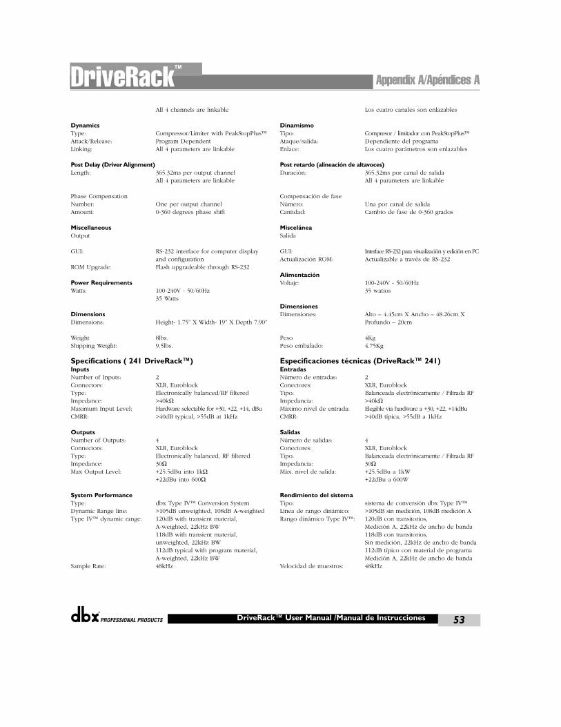
®
All 4 channels are linkable
DynamicsType: Compressor/Limiter with PeakStopPlus™Attack/Release: Program DependentLinking: All 4 parameters are linkable
Post Delay (Driver Alignment)Length: 365.32ms per output channel
All 4 parameters are linkable
Phase CompensationNumber: One per output channelAmount: 0-360 degrees phase shift
MiscellaneousOutput
GUI: RS-232 interface for computer display and configuration
ROM Upgrade: Flash upgradeable through RS-232
Power RequirementsWatts: 100-240V - 50/60Hz
35 Watts
DimensionsDimensions: Height- 1.75” X Width- 19” X Depth 7.90”
Weight 8lbs.Shipping Weight: 9.5lbs.
Specifications ( 241 DriveRack™)InputsNumber of Inputs: 2 Connectors: XLR, EuroblockType: Electronically balanced/RF filteredImpedance: >40kΩMaximum Input Level: Hardware selectable for +30, +22, +14, dBuCMRR: >40dB typical, >55dB at 1kHz
OutputsNumber of Outputs: 4Connectors: XLR, EuroblockType: Electronically balanced, RF filteredImpedance: 30ΩMax Output Level: +25.5dBu into 1kΩ
+22dBu into 600Ω
System PerformanceType: dbx Type IV™ Conversion SystemDynamic Range line: >105dB unweighted, 108dB A-weightedType IV™ dynamic range: 120dB with transient material,
A-weighted, 22kHz BW118dB with transient material,unweighted, 22kHz BW112dB typical with program material,A-weighted, 22kHz BW
Sample Rate: 48kHz
Los cuatro canales son enlazables
DinamismoTipo: Compresor / limitador con PeakStopPlus™Ataque/salida: Dependiente del programaEnlace: Los cuatro parámetros son enlazables
Post retardo (alineación de altavoces)Duración: 365.32ms por canal de salida
All 4 parameters are linkable
Compensación de faseNúmero: Una por canal de salidaCantidad: Cambio de fase de 0-360 grados
MisceláneaSalida
GUI: Interface RS-232 para visualización y edición en PCActualización ROM: Actualizable a través de RS-232
AlimentaciónVoltaje: 100-240V - 50/60Hz
35 watios
DimensionesDimensiones: Alto – 4.45cm X Ancho – 48.26cm X
Profundo – 20cm
Peso 4KgPeso embalado: 4.75Kg
Especificaciones técnicas (DriveRack™ 241)EntradasNúmero de entradas: 2 Conectores: XLR, EuroblockTipo: Balanceada electrónicamente / Filtrada RFImpedancia: >40kΩMáximo nivel de entrada: Elegible vía hardware a +30, +22, +14dBuCMRR: >40dB típica, >55dB a 1kHz
SalidasNúmero de salidas: 4Conectores: XLR, EuroblockTipo: Balanceada electrónicamente / Filtrada RFImpedancia: 30ΩMáx. nivel de salida: +25.5dBu a 1kW
+22dBu a 600W
Rendimiento del sistemaTipo: sistema de conversión dbx Type IV™ Línea de rango dinámico: >105dB sin medición, 108dB medición ARango dinámico Type IV™: 120dB con transitorios,
Medición A, 22kHz de ancho de banda118dB con transitorios,Sin medición, 22kHz de ancho de banda112dB típico con material de programaMedición A, 22kHz de ancho de banda
Velocidad de muestros: 48kHz
Appendix A/Apéndices ADriveRack™
DriveRack™ User Manual /Manual de Instrucciones 53
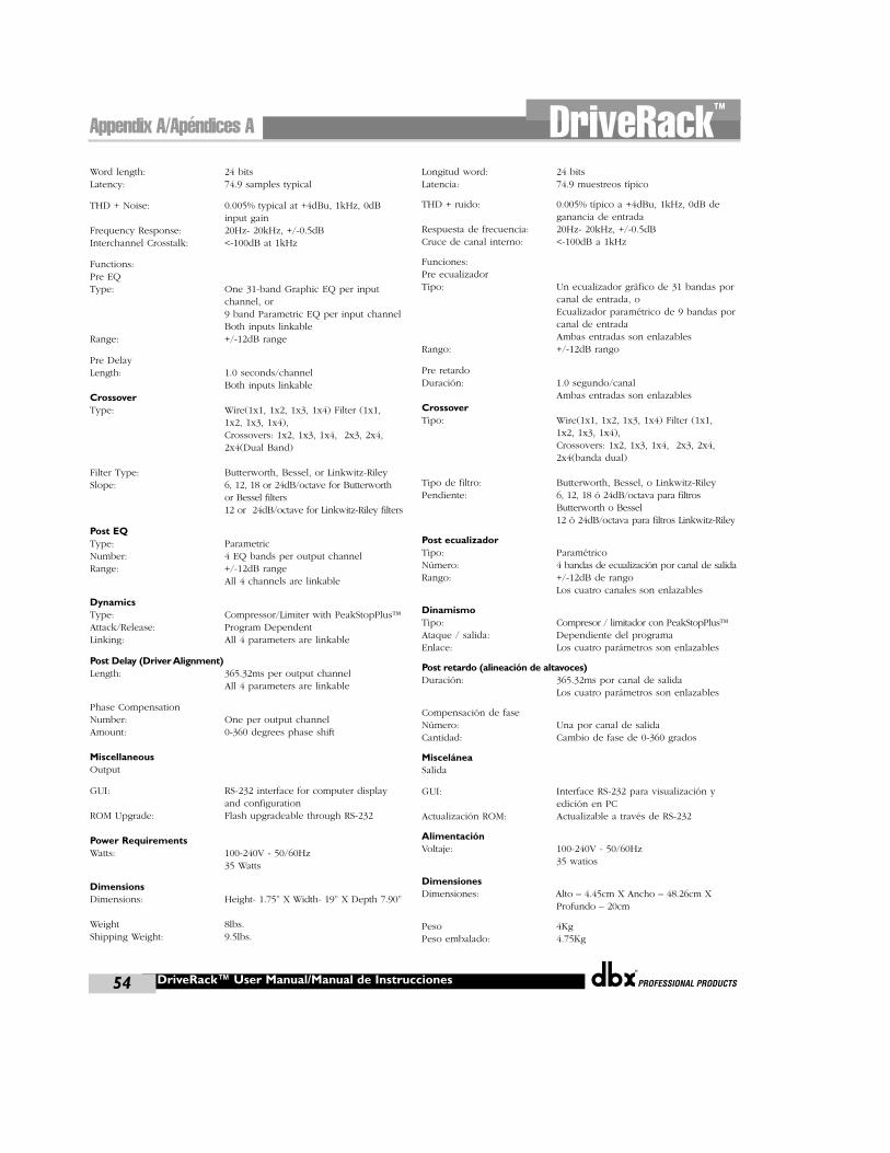
®
DriveRack™ User Manual/Manual de Instrucciones54
Appendix A/Apéndices A DriveRack™
Word length: 24 bitsLatency: 74.9 samples typical
THD + Noise: 0.005% typical at +4dBu, 1kHz, 0dB input gain
Frequency Response: 20Hz- 20kHz, +/-0.5dBInterchannel Crosstalk: <-100dB at 1kHz
Functions:Pre EQType: One 31-band Graphic EQ per input
channel, or9 band Parametric EQ per input channelBoth inputs linkable
Range: +/-12dB range
Pre DelayLength: 1.0 seconds/channel
Both inputs linkableCrossoverType: Wire(1x1, 1x2, 1x3, 1x4) Filter (1x1,
1x2, 1x3, 1x4), Crossovers: 1x2, 1x3, 1x4, 2x3, 2x4, 2x4(Dual Band)
Filter Type: Butterworth, Bessel, or Linkwitz-RileySlope: 6, 12, 18 or 24dB/octave for Butterworth
or Bessel filters12 or 24dB/octave for Linkwitz-Riley filters
Post EQType: ParametricNumber: 4 EQ bands per output channelRange: +/-12dB range
All 4 channels are linkable
DynamicsType: Compressor/Limiter with PeakStopPlus™Attack/Release: Program DependentLinking: All 4 parameters are linkable
Post Delay (Driver Alignment)Length: 365.32ms per output channel
All 4 parameters are linkable
Phase CompensationNumber: One per output channelAmount: 0-360 degrees phase shift
MiscellaneousOutput
GUI: RS-232 interface for computer display and configuration
ROM Upgrade: Flash upgradeable through RS-232
Power RequirementsWatts: 100-240V - 50/60Hz
35 Watts
DimensionsDimensions: Height- 1.75” X Width- 19” X Depth 7.90”
Weight 8lbs.Shipping Weight: 9.5lbs.
Longitud word: 24 bitsLatencia: 74.9 muestreos típico
THD + ruido: 0.005% típico a +4dBu, 1kHz, 0dB de ganancia de entrada
Respuesta de frecuencia: 20Hz- 20kHz, +/-0.5dBCruce de canal interno: <-100dB a 1kHz
Funciones:Pre ecualizadorTipo: Un ecualizador gráfico de 31 bandas por
canal de entrada, oEcualizador paramétrico de 9 bandas porcanal de entradaAmbas entradas son enlazables
Rango: +/-12dB rango
Pre retardoDuración: 1.0 segundo/canal
Ambas entradas son enlazablesCrossoverTipo: Wire(1x1, 1x2, 1x3, 1x4) Filter (1x1,
1x2, 1x3, 1x4), Crossovers: 1x2, 1x3, 1x4, 2x3, 2x4, 2x4(banda dual)
Tipo de filtro: Butterworth, Bessel, o Linkwitz-RileyPendiente: 6, 12, 18 ó 24dB/octava para filtros
Butterworth o Bessel12 ó 24dB/octava para filtros Linkwitz-Riley
Post ecualizadorTipo: ParamétricoNúmero: 4 bandas de ecualización por canal de salidaRango: +/-12dB de rango
Los cuatro canales son enlazables
DinamismoTipo: Compresor / limitador con PeakStopPlus™Ataque / salida: Dependiente del programaEnlace: Los cuatro parámetros son enlazables
Post retardo (alineación de altavoces)Duración: 365.32ms por canal de salida
Los cuatro parámetros son enlazables
Compensación de faseNúmero: Una por canal de salidaCantidad: Cambio de fase de 0-360 grados
MisceláneaSalida
GUI: Interface RS-232 para visualización y edición en PC
Actualización ROM: Actualizable a través de RS-232
AlimentaciónVoltaje: 100-240V - 50/60Hz
35 watios
DimensionesDimensiones: Alto – 4.45cm X Ancho – 48.26cm X
Profundo – 20cm
Peso 4KgPeso embalado: 4.75Kg
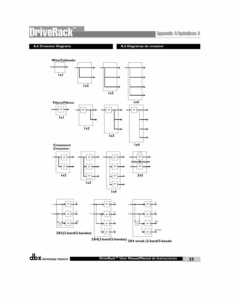
®
Wire/Caldeado:
1x1
1x2
1x3
1x4
Linked/Enlazado
1x1
1x2
1x3
1x4
2X3(2-band/2-bandas)
BPH
BP
BP
H
+Sub
L
R
L
R
L
R
Filters/Filtros:
2X4(2-band/2-bandas)
BPH
BP
BP
H
L
BPL
+
2X4 w/sub (3-band/3-bandas
BPH
BP
BP
H
Sub
BPSub-Sub
BP BP BP BP
1x2
1x3
1x4
Crossovers/Crossover:
BP
BP
BP
BP
BP
BP
BP
BP
BP
2x2
BP
BP
Appendix A/Apéndices ADriveRack™
DriveRack™ User Manual/Manual de Instrucciones 55
A.6 Crossover Diagrams A.6 Diagramas de crossover
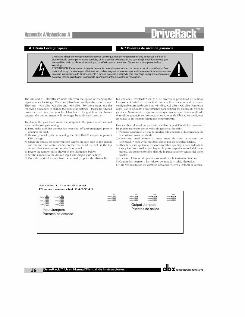
®
DriveRack™ User Manual/Manual de Instrucciones56
Appendix A/Apéndices A DriveRack™
A.7 Gain Level Jumpers A.7 Puentes de nivel de ganancia
CAUTION: These servicing instructions are for use by qualified service personnel only. To reduce the risk of electric shock, do not perform any servicing other than that contained in the operating instructions unless you are qualified to do so. Refer all servicing to qualified service personnel. Disconnect mains power before servicing.PRECAUCION: Estas instrucciones de reparación son sólo para su uso por personal técnico cualificado. Para reducir el riesgo de descargas eléctricas, no realice ninguna reparación aparte de las específicamente incluidas en estas instrucciones de funcionamiento a menos que esté cualificado para ello. Dirija cualquier reparación a personal técnico cualificado. Desconecte la corriente antes de cualquier reparación.
240/241 Main Board
Output JumpersPuentes de salidaInput Jumpers
Puentes de entrada
+22dBu
Ch1
+30dBu
+14dBu
+22dBu
Ch2
+30dBu
+14dBu+22dBu
Ch1
+30dBu
+14dBu+22dBu
Ch2
+30dBu
+14dBu+22dBu
Ch3
+30dBu
+14dBu+22dBu
Ch4
+30dBu
+14dBu
Placa base del 240/241
The 240 and 241 DriveRack™ units offer you the option of changing theinput gain level settings. There are 3 hardware configurable gain settings.They are: +14 dBu, +22 dBu and +30 dBu. For these cases, use thefollowing procedure to change the gain level settings. Please be advisedhowever, that once the gain level has been changed from the factorysettings, the output meters will no longer be calibrated correctly.
To change the gain level, move the jumpers to the pins that are markedwith the desired gain setting1) First, make sure that the unit has been shut off and unplugged prior to
opening the unit.2) Ground yourself prior to opening the DriveRack™ chassis to prevent
ESD damage.3) Open the chassis by removing five screws on each side of the chassis
and the top two center screws on the rear panel, as well as the topcenter allen screw located on the front panel
4) Locate the jumper block shown in the illustration below:5) Set the jumpers to the desired input and output gain settings. 6) Once the desired settings have been made, replace the chassis lid.
Las unidades DriveRack™ 240 y 241le ofrecen la posibilidad de cambiarlos ajustes del nivel de ganancia de entrada. Hay tres valores de gananciaconfigurables en hardware. Son: +14 dBu, +22 dBu y +30 dBu. Para estoscasos, use el siguiente procedimiento para cambiar los valores de nivel deganancia. No obstante, tenga en cuenta que una vez que haya modificadoel nivel de ganancia con respecto a los valores de fábrica, los medidoresde salida ya no estarán calibrados correctamente.
Para cambiar el nivel de ganancia, cambie la posición de los puentes alas puntas marcadas con el valor de ganancia deseado.1) Primero, asegúrese de que la unidad está apagada y desconectada de
la corriente antes de abrirla2) Conéctese usted mismo a tierra antes de abrir la carcasa del
DriveRack™ para evitar posibles daños por electricidad estática.3) Abra la carcasa quitando los cinco tornillos que hay a cada lado de la
caja y los dos tornillos que hay en la parte superior central del paneltrasero, así como el tornillo allen de la parte superior central del panelfrontal.
4) Localice el bloque de puentes mostrado en la ilustración inferior.5) Cambie los puentes a los valores de entrada y salida deseados.6) Una vez realizados los cambios deseados, vuelva a colocar la carcasa.
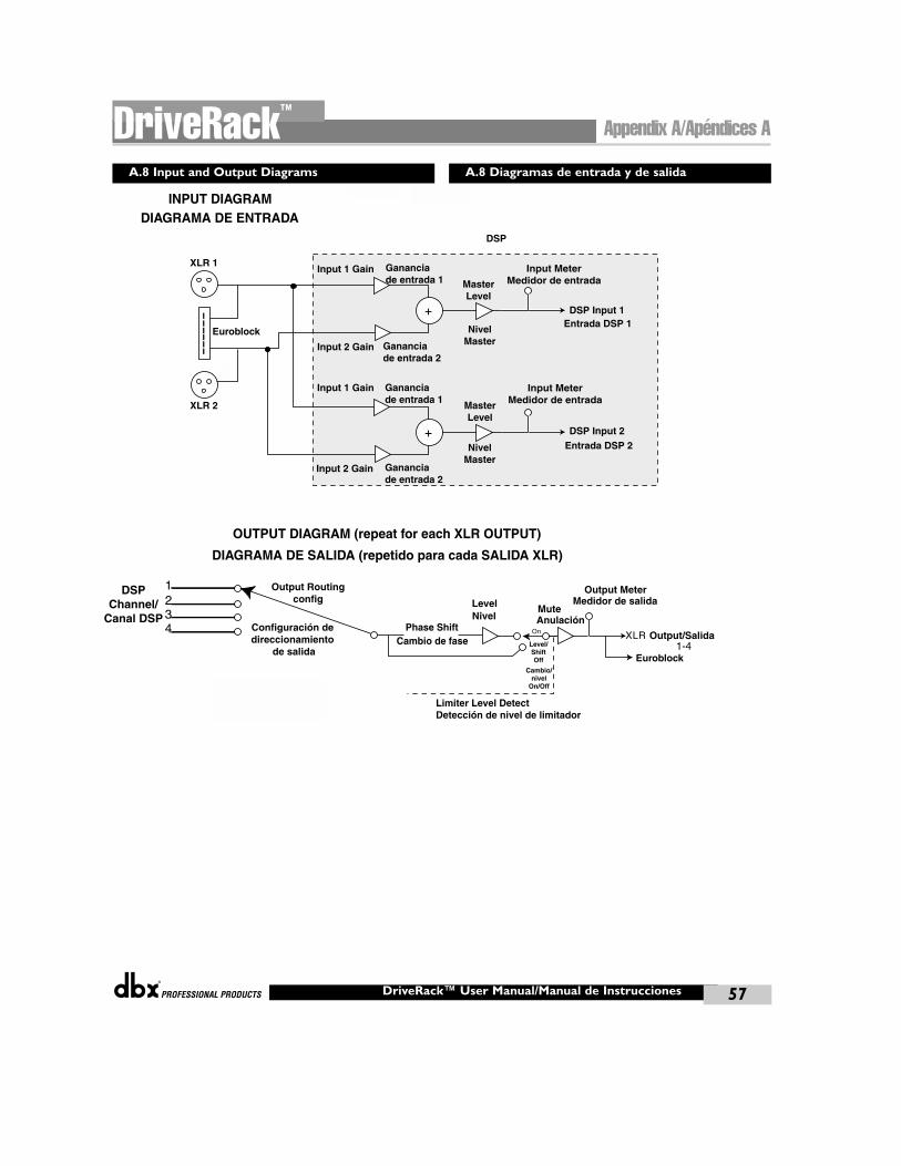
®
1-4
Input 1 Gain
DSP
Limiter Level DetectDetección de nivel de limitador
DSP Input 1
Euroblock
DSP Input 2
XLR 1
XLR 2
Euroblock
Input 2 Gain
MasterLevel
NivelMaster
Entrada DSP 1
MasterLevel
NivelMaster
Input MeterMedidor de entrada
Entrada DSP 2
OUTPUT DIAGRAM (repeat for each XLR OUTPUT)
INPUT DIAGRAMDIAGRAMA DE ENTRADA
DIAGRAMA DE SALIDA (repetido para cada SALIDA XLR)
Phase ShiftCambio de fase Level/
ShiftOff
Cambio/nivel
On/Off
LevelNivel
MuteAnulación
Output MeterMedidor de salida
Output/Salida
Output Routingconfig
Configuración de direccionamiento
de salida
DSPChannel/
Canal DSP
Input MeterMedidor de entrada
Gananciade entrada 1
Gananciade entrada 2
Input 1 Gain Gananciade entrada 1
Input 2 Gain Gananciade entrada 2
Appendix A/Apéndices ADriveRack™
DriveRack™ User Manual/Manual de Instrucciones 57
A.8 Input and Output Diagrams A.8 Diagramas de entrada y de salida

®
DriveRack™ User Manual/Manual de Instrucciones58
Appendix A/Apéndices A DriveRack™
USER NOTES: NOTAS DEL USUARIO:

8760 South SandyParkway • Sandy, Utah
84070Phone: (801) 568-7660
Fax (801) 568-7662 Int’l Fax: (801) 568-7583Questions or comments?
E-mail us at:[email protected] visit our World Wide
Web home page at:www.dbxpro.com
8760 South SandyParkway • Sandy, Utah
84070Teléfono: (801) 568-7660
Fax (801) 568-7662 Fax internacional: (801)
568-7583¿Tiene alguna pregunta o
comentario?Envíenos un correo
electrónico a:[email protected] visite nuestra página
web en Web home pageat: www.dbxpro.com
A Harman International Company
18-6386-A
®