Complete Custom Metal Building Design and Pricing …metalbuildingdepot.com/pdf/iqs.pdfComplete...
39
Complete Custom Metal Building Design and Pricing Software The most advanced metal building design and pricing system on the planet!
Transcript of Complete Custom Metal Building Design and Pricing …metalbuildingdepot.com/pdf/iqs.pdfComplete...

Complete Custom Metal Building Design and Pricing Software
The most advanced metal building design and pricing system on the planet!

�
Ladies and Gentlemen, we have arrived! Welcome to IQS – the most advanced metal building
design and pricing system on the planet! I would like to personally thank you for your interest
in our products and services!
With IQS, the power is in your hands. You are at the command of the world’s first and only “real-time” design
system, giving you the power to create an almost endless array of pre-engineered buildings in seconds. You will not
find another system that gives you the flexibility to create structures for Add-On buildings, Lean-To buildings, Open
Walled, Non-symmetrical shapes, Single Slopes, Gables, Modular
buildings to 150,000 square feet and an almost endless array of
aircraft hangar buildings can be created using IQS – including
modular hangar structures with multiple hangar door openings.
All of this is available to you in a fully-rendered 3D graphical
interface with the power to produce a set of approval drawings,
literally in seconds.
If you’re thinking it sounds too good to be true, we are not
surprised. Not a single company in the pre-engineered building
business has accomplished this feat… until now. An enormous effort
has been made to provide you with this revolutionary system.
Not only do we have plans to continue the further development of
IQS, it is our core focus. As an IQS user, you will have the power
of design, but more importantly you will be able to use business
logic built into the system. What this means to you is that you will
be able to search jobs by customer name, city, zip, phone number or any other customer related data. In today’s fast
paced world you need complete flexibility in your system, and we are bringing it all to you.
Our future plans include a host of enhancements and by late 2008 we should be on track to release a new design
add-on to IQS. This plug-in will allow you to combine projects together, like high-low roof step downs, or combining
2 to 10 different buildings together. It will produce Foundation Plans and specs on-the-fly by December of 2008
– bringing a force of value unmatched in our industry.
Sincerely,
Mark Moore
Founder & Chairman
ICON Building Systems
IQS Introduction
�
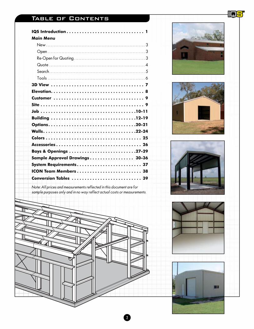
Table of Contents
IQS Introduction . . . . . . . . . . . . . . . . . . . . . . . . . . . . . . 1
Main Menu
New . . . . . . . . . . . . . . . . . . . . . . . . . . . . . . . . . . . . . . . . . . . . . . . . . . . . . . . . . . . . . . . . 3
Open . . . . . . . . . . . . . . . . . . . . . . . . . . . . . . . . . . . . . . . . . . . . . . . . . . . . . . . . . . . . . . . 3
Re-Open for Quoting . . . . . . . . . . . . . . . . . . . . . . . . . . . . . . . . . . . . . . . . . . . . . . 3
Quote . . . . . . . . . . . . . . . . . . . . . . . . . . . . . . . . . . . . . . . . . . . . . . . . . . . . . . . . . . . . . . 4
Search . . . . . . . . . . . . . . . . . . . . . . . . . . . . . . . . . . . . . . . . . . . . . . . . . . . . . . . . . . . . . . 5
Tools . . . . . . . . . . . . . . . . . . . . . . . . . . . . . . . . . . . . . . . . . . . . . . . . . . . . . . . . . . . . . . . 6
3D View . . . . . . . . . . . . . . . . . . . . . . . . . . . . . . . . . . . . 7
Elevation . . . . . . . . . . . . . . . . . . . . . . . . . . . . . . . . . . . . 8
Customer . . . . . . . . . . . . . . . . . . . . . . . . . . . . . . . . . . . 9
Site . . . . . . . . . . . . . . . . . . . . . . . . . . . . . . . . . . . . . . . . 9
Job . . . . . . . . . . . . . . . . . . . . . . . . . . . . . . . . . . . . .10-11
Building . . . . . . . . . . . . . . . . . . . . . . . . . . . . . . . . .12-19
Options . . . . . . . . . . . . . . . . . . . . . . . . . . . . . . . . . .20-21
Walls . . . . . . . . . . . . . . . . . . . . . . . . . . . . . . . . . . . .22-24
Colors . . . . . . . . . . . . . . . . . . . . . . . . . . . . . . . . . . . . . 25
Accessories . . . . . . . . . . . . . . . . . . . . . . . . . . . . . . . . . 26
Bays & Openings . . . . . . . . . . . . . . . . . . . . . . . . . .27-29
Sample Approval Drawings . . . . . . . . . . . . . . . . . 30-36
System Requirements . . . . . . . . . . . . . . . . . . . . . . . . . 37
ICON Team Members . . . . . . . . . . . . . . . . . . . . . . . . . 38
Conversion Tables . . . . . . . . . . . . . . . . . . . . . . . . . . . 39
Note: All prices and measurements reflected in this document are for sample purposes only and in no way reflect actual costs or measurements.

�
Main Menu - Open
Opens an existing job based on the established job number.
Use the check box to automatically retrieve the latest revision of the job number entered.
Open an older version on the job number entered by selecting from the drop down menu.
Bay Left wallDoor opening Window opening Wide opening
Quote 391644 - 40 x 60 x 14 8:12 - IQSQuote 391644 - 40 x 60 x 14 8:12 - IQS
12.0
16.0
12.0
0.0
0.0
0.0
Distance unit: Imperial Revision: 9 Status: Waiting for approval Sales person: Mark Moore Dealer: ICON
Find duplicate customer
width
width
width
Bay 1:
Bay 2:
Bay 3:
elevation
elevation
elevation
open
open
open
Elevation3D view
Bays & Openings
8.012
d1 d2 d3 d4 d5
2' 3' 1' 6
"3' 6' 6
"
8' 6' 6
"
3' 1' 6
"3' 2'
4' 4'40'
14' 14'
20'
12' 12'16'
20'
Open Quote Search ToolsRe-open for quotingNew Help
AccessoriesColorsWallsOptionsBuildingJobSiteCustomer
Customer
Cell ( ) -Fax( ) -
Phone 1&2 ( ) - x ( ) - x
Address
Company
Name F/L
City Seguin State Texas
Lead source Lead status NonePhone
Zip 78155 County Guadalupe
Main Menu - Re-Open For Quoting
Once a purchase order is created for a job, IQS does not allow further modifications to the job. This is necessary because the purchase order should reflect the job’s current state, and if changes are made, the purchase order is no longer up to date.
If changes are necessary, click the Re-open for quoting menu item and the job is unlocked. Any changes to the job effectively invalidate all prior purchase order documents for that job. Any revision of a job can be re-opened at any time.
Main Menu - New
The New menu item opens a new window with a new job with a default building configuration.

�
Click to generate a price list or to save changes to your currently open job.Note: a quote must be run in order to save any changes to your job to ensure all data related to this job is current
In the quote window, you will have the following selections:
Save - saves the current job with revisions
Create a Purchase Order - generates a multi-page purchase order document in PDF format for the customer to review and sign, including approval drawings of the building. Once the purchase order is created it can still be downloaded later using the Download purchase order buttonNote: Once a PO is created, the job cannot be revised unless it is re-opened for quoting. This option will appear in the main menu as an “open lock” if available to a job. The entire job will not need to be started over.
Print - sends the pricing overview to the printer
Print Preview - Preview the document as it will be printed prior to actually printing
Main Menu - Quote
Bay Left wallDoor opening Window opening Wide opening
Quote 391644 - 40 x 60 x 14 8:12 - IQSQuote 391644 - 40 x 60 x 14 8:12 - IQS
12.0
16.0
12.0
0.0
0.0
0.0
Distance unit: Imperial Revision: 9 Status: Waiting for approval Sales person: Mark Moore Dealer: ICON
width
width
width
Bay 1:
Bay 2:
Bay 3:
elevation
elevation
elevation
open
open
open
Elevation3D view
Bays & Openings
8.012
d1 d2 d3 d4 d5
2' 3' 1' 6
"3' 6' 6
"
8' 6' 6
"
3' 1' 6
"3' 2'
4' 4'40'
14' 14'
20'
12' 12'16'
20'
Open Quote Search ToolsNew Help
AccessoriesColorsWallsOptionsBuildingJobSiteCustomer
Building
Loads
Roof Pitch : 12 W L Hb Hf
Type ProfileFully sheeted
Angle Bypass
TaperedTapered
Gable
RF Rafter RF Column
Base Cond. SW Girt
Insets right Interior column editorInsets left
Dead Live Ground Snow Collateral
0
14.014.060.040.0
2.5 20.0 12.0 0.5
8.0
0

�
Main Menu - Search
Search for existing jobs using any of the information fields provided. Go directly to a specific job(s) by entering the customer’s name, or search all jobs from a certain sales person from within a designated zip code.
Select from the options retrieved from your search and open the latest version or a previously saved revision.Note: Click on the column headers to organize the search results in ascending or descending order (ex: dates modified, city, state, etc.)
Bay Left wallDoor opening Window opening Wide opening
Quote 391644 - 40 x 60 x 14 8:12 - IQSQuote 391644 - 40 x 60 x 14 8:12 - IQS
12.0
16.0
12.0
0.0
0.0
0.0
Distance unit: Imperial Revision: 9 Status: Waiting for approval Sales person: Mark Moore Dealer: ICON
width
width
width
Bay 1:
Bay 2:
Bay 3:
elevation
elevation
elevation
open
open
open
Elevation3D view
Bays & Openings
8.012
d1 d2 d3 d4 d5
2' 3' 1' 6
"3' 6' 6
"
8' 6' 6
"
3' 1' 6
"3' 2'
4' 4'40'
14' 14'
20'
12' 12'16'
20'
Open Quote Search ToolsNew Help
AccessoriesColorsWallsOptionsBuildingJobSiteCustomer
Job
IBC 00 B90.0Code Wind MPH: Exp.
Standard Package (No Cert.) ($0.00)Eng. Pkg.
0.197Seismic Coef. Seismic Zone ImperialMeasurements system
Notes
0.00Extra Items Price 0.00Fees discountFoundation plans

�
Settings - In the settings, the 3D rendering type can be changed. By default the rendering type is DirectX, which is supported by most machines.
Alternatively, OpenGL and GDI can be used. GDI rendering displays the building as a wire frame
Save 3D screenshot - saves a PNG image file of the 3D rendering as it appears in the 3D view frame of the IQS interfaceNote: Save multiple images at different angles to email to clients.
Note: PNG image files utilize RGB color format with a 72 dpi image resolution.
Print 3D screenshot - sends the 3D rendering to your specified printer. The rendering prints as it appears in the 3D view frame of the IQS interfaceNote: The dark gray background of the 3D view will be omitted from the actual printout. Only the building will print.
Main Menu - Tools
Bay Left wallDoor opening Window opening Wide opening
Quote 391644 - 40 x 60 x 14 8:12 - IQSQuote 391644 - 40 x 60 x 14 8:12 - IQS
12.0
16.0
12.0
0.0
0.0
0.0
Distance unit: Imperial Revision: 9 Status: Waiting for approval Sales person: Mark Moore Dealer: ICON
width
width
width
Bay 1:
Bay 2:
Bay 3:
elevation
elevation
elevation
open
open
open
Elevation3D view
Bays & Openings
8.012
d1 d2 d3 d4 d5
2' 3' 1' 6
"3' 6' 6
"
8' 6' 6
"
3' 1' 6
"3' 2'
4' 4'40'
14' 14'
20'
12' 12'16'
20'
Open Quote SearchNew Help
AccessoriesColorsWallsOptionsBuildingJobSiteCustomer
Building
Loads
Roof Pitch : 12 W L Hb Hf
Type ProfileFully sheeted
Angle Bypass
TaperedTapered
Gable
RF Rafter RF Column
Base Cond. SW Girt
Insets right Interior column editorInsets left
Dead Live Ground Snow Collateral
0
14.014.060.040.0
2.5 20.0 12.0 0.5
8.0
0
Tools
Settings
Save 3D screenshot
Print 3D screenshot
Disable internal interface
Sample building rendered using GDI wire frame.

�
3D View
Bay Left wallDoor opening Window opening Wide opening
Quote 391644 - 40 x 60 x 14 8:12 - IQSQuote 391644 - 40 x 60 x 14 8:12 - IQS
12.0
16.0
12.0
0.0
0.0
0.0
Distance unit: Imperial Revision: 9 Status: Waiting for approval Sales person: Mark Moore Dealer: ICON
width
width
width
Bay 1:
Bay 2:
Bay 3:
elevation
elevation
elevation
open
open
open
Elevation3D view
Bays & Openings
8.012
d1 d2 d3 d4 d5
2' 3' 1' 6
"3' 6' 6
"
8' 6' 6
"
3' 1' 6
"3' 2'
4' 4'40'
14' 14'
20'
12' 12'16'
20'
Open Quote Search ToolsNew Help
AccessoriesColorsWallsOptionsBuildingJobSiteCustomer
Options
NoneWall
NoneRoof
Insulation
NoneWall
NoneRoof
Liner
0.197Base trim
Miscelaneous
Gutter
Sheet notch Wainscot height
Cover trim
Click, hold and drag anywhere within this frame to reposition the 3D rendering.
Rotate the rendering by using the slider arrow directly underneath.
Zoom in and out of the 3D rendering using the scroll-wheel on your mouse.Note: View a 3D elevation and the corresponding elevation drawing by selecting one of the four elevation views represented in the lower right corner of the 3D view frame.
Note: To print or save an image file of the 3D rendering, select “Tools” from the main menu.Quote 391644 - 40 x 60 x 14 8:12 - IQSQuote 391644 - 40 x 60 x 14 8:12 - IQSOpen Quote Search Tools
12.0
16.0
12.0
12.0
16.0
12.0
Distance unit: Imperial Revision: 9 Status: Waiting for approval Sales person: Mark Moore Dealer: ICON
Bay Left wallDoor opening Window opening Wide opening
width
width
width
Bay 1:
Bay 2:
Bay 3:
elevation
elevation
elevation
Elevation3D view
Bays & OpeningsAccessoriesColorsWallsOptionsJobSiteCustomer Building
d1 d2 d3
2' 3' 1' 6
"3' 6' 6
"
8' 6' 6
"
4' 40'
14'
Loads
Roof Pitch : 12 W L Hb Hf
Type ProfileFully sheeted
Angle Bypass
TaperedTapered
Gable
RF Rafter RF Column
Base Cond. SW Girt
Insets right Interior column editorInsets left
Dead Live Ground Snow Collateral
0
14.014.060.040.0
2.5 20.0 12.0 0.5
8.0
0

�
Bay Left wallDoor opening Window opening Wide opening
Quote 391644 - 40 x 60 x 14 8:12 - IQSQuote 391644 - 40 x 60 x 14 8:12 - IQS
12.0
16.0
12.0
0.0
0.0
0.0
Distance unit: Imperial Revision: 9 Status: Waiting for approval Sales person: Mark Moore Dealer: ICON
width
width
width
Bay 1:
Bay 2:
Bay 3:
elevation
elevation
elevation
open
open
open
Elevation3D view
Bays & Openings
8.012
d1 d2 d3 d4 d5
2' 3' 1' 6
"3' 6' 6
"
8' 6' 6
"
3' 1' 6
"3' 2'
4' 4'40'
14' 14'
20'
12' 12'16'
20'
Open Quote Search ToolsNew Help
AccessoriesColorsWallsOptionsBuildingJobSiteCustomer
Building
Loads
Roof Pitch : 12 W L Hb Hf
Type ProfileFully sheeted
Angle Bypass
TaperedTapered
Gable
RF Rafter RF Column
Base Cond. SW Girt
Insets right Interior column editorInsets left
Dead Live Ground Snow Collateral
0
14.014.060.040.0
2.5 20.0 12.0 0.5
8.0
0
Click, hold and drag anywhere within this frame to reposition the elevation drawing.
Zoom in and out of the elevation drawing using the scroll-wheel on your mouse.Note: View an elevation drawing and the corresponding 3D elevation by selecting one of the four elevation views represented in the lower right corner of the 3D view frame.Quote 391644 - 40 x 60 x 14 8:12 - IQSQuote 391644 - 40 x 60 x 14 8:12 - IQS
Open Quote Search Tools
12.0
16.0
12.0
12.0
16.0
12.0
Distance unit: Imperial Revision: 9 Status: Waiting for approval Sales person: Mark Moore Dealer: ICON
Bay Left wallDoor opening Window opening Wide opening
width
width
width
Bay 1:
Bay 2:
Bay 3:
elevation
elevation
elevation
Elevation3D view
Bays & OpeningsAccessoriesColorsWallsOptionsJobSiteCustomer Building
d1 d2 d3
2' 3' 1' 6
"3' 6' 6
"
8' 6' 6
"4' 40'
14'
Loads
Roof Pitch : 12 W L Hb Hf
Type ProfileFully sheeted
Angle Bypass
TaperedTapered
Gable
RF Rafter RF Column
Base Cond. SW Girt
Insets right Interior column editorInsets left
Dead Live Ground Snow Collateral
0
14.014.060.040.0
2.5 20.0 12.0 0.5
8.0
0
Elevation

�
Bay Left wallDoor opening Window opening Wide opening
Quote 391644 - 40 x 60 x 14 8:12 - IQSQuote 391644 - 40 x 60 x 14 8:12 - IQS
12.0
16.0
12.0
0.0
0.0
0.0
Distance unit: Imperial Revision: 9 Status: Waiting for approval Sales person: Mark Moore Dealer: ICON
Find duplicate customer
width
width
width
Bay 1:
Bay 2:
Bay 3:
elevation
elevation
elevation
open
open
open
Elevation3D view
Bays & Openings
8.012
d1 d2 d3 d4 d5
2' 3' 1' 6
"3' 6' 6
"
8' 6' 6
"
3' 1' 6
"3' 2'
4' 4'40'
14' 14'
20'
12' 12'16'
20'
Open Quote Search ToolsNew Help
AccessoriesColorsWallsOptionsBuildingJobSiteCustomer
Customer
Cell ( ) -Fax( ) -
Phone 1&2 ( ) - x ( ) - x
Address
Company
Name F/L
City Seguin State Texas
Lead source Lead status NonePhone
Zip 78155 County Guadalupe
Quote 391644 - 40 x 60 x 14 8:12 - IQSQuote 391644 - 40 x 60 x 14 8:12 - IQSOpen Quote Search Tools
12.0
16.0
12.0
12.0
16.0
12.0
Distance unit: Imperial Revision: 9 Status: Waiting for approval Sales person: Mark Moore Dealer: ICON
Bay Left wallDoor opening Window opening Wide opening
width
width
width
Bay 1:
Bay 2:
Bay 3:
elevation
elevation
elevation
Elevation3D view
Bays & OpeningsAccessoriesColorsWallsOptionsBuildingJobCustomer Site
8.012
d1 d2 d3 d4 d5
2' 3' 1' 6
"3' 6' 6
"
8' 6' 6
"
3' 1' 6
"3' 2'
4' 4'40'
14' 14'
20'
12' 12'16'
20'
Use customer data
City: Seguin State:
Contact F/L:
( ) -Fax:Phone: ( ) - x
Zip: 78155 County: Guadalupe
Address:
Project:
Texas
Customer
Site
Input all relevant customer information in this window. If this project pertains to an existing customer, select “Find Duplicate Customer” to import the contact information from a previous or existing job.
Entering the zip code will automatically populate the City, State and County fields. Also the building code, seismic zone, seismic coefficient, wind speed and ground snow load are set based on the zip code. These can be found in the job and building tabs.
To quote a job, at least the zip code and lead source have to be filled in.
Select “Use Customer Data” to apply the same information from the Customer Tab to the Site Tab. If the job site information is different, input all relevant data in this window.

�0
Job
Much of this data will be automatically populated based on the Site information provided. The Measurement system by default is “Imperial”, which is standard for continental U.S. measurements.
Building Code Building codes are intended to provide for the safe use of buildings and structures under “normal” conditions. The code describes exactly how each part of the building should be loaded and designed. These loads are based on Snow load, Wind Speed, Seismic Coefficient (earthquake), Collateral load and Exposure. These loads will be applied in various “Design Combination” to determine the most critical loading. From these combinations all member sizes and spacing will be determined.
IQS determines the building code based on the job site’s zip code. The most common building code is IBC.
For a more detailed explanation of building codes see topic Building Codes Explained.
Wind Speed As wind blows it places pressure and suction on the building surfaced. The exact pressure/load is based not only on the formulas and tables contained in the specific building code chosen, but also the size and shape of your building. By entering the Wind Speed, IQS designs the optimum structural member sizes and their spacing.
Wind Exposure The characteristics of ground surface irregularities (natural topography and vegetation as well as constructed features) for the site at which the building is to be constructed.
Bay Left wallDoor opening Window opening Wide opening
Quote 391644 - 40 x 60 x 14 8:12 - IQSQuote 391644 - 40 x 60 x 14 8:12 - IQS
12.0
16.0
12.0
0.0
0.0
0.0
Distance unit: Imperial Revision: 9 Status: Waiting for approval Sales person: Mark Moore Dealer: ICON
width
width
width
Bay 1:
Bay 2:
Bay 3:
elevation
elevation
elevation
open
open
open
Elevation3D view
Bays & Openings
8.012
d1 d2 d3 d4 d5
2' 3' 1' 6
"3' 6' 6
"
8' 6' 6
"
3' 1' 6
"3' 2'
4' 4'40'
14' 14'
20'
12' 12'16'
20'
Open Quote Search ToolsNew Help
AccessoriesColorsWallsOptionsBuildingJobSiteCustomer
Job
IBC 00 B90.0Code Wind MPH: Exp.
Standard Package (No Cert.) ($0.00)Eng. Pkg.
0.197Seismic Coef. Seismic Zone ImperialMeasurements system
Notes
0.00Extra Items Price 0.00Fees discountFoundation plans

��
Job
Wind Exposure (cont .) Exposure A: Large city centers with at least 50% of the buildings having a height in excess of 70 feet.
Exposure B: Urban and suburban areas, wooded areas, or other terrain with numerous closely spaced obstructions having the size of single-family dwellings or larger.
Exposure C: Open terrain with scattered obstructions.
Exposure D: Flat, unobstructed areas exposed to wind flowing over open water (excluding shorelines in hurricane prone regions) for a distance of at least 1 mile.
Seismic Coefficient This is the influence of earthquake activity on your steel building. The higher this number the more influence seismic has or the greater the seismic loading. Some building codes such as the Uniform Building Code (UBC) or the California Building Code (CBC) also use seismic zone. These also influence seismic design; Zone 0 having the least influence and Zone 4 having the greatest.
Seismic Zone / Site Classification The seismic zone/site classification is a gauge of your soil’s capacity to transmit activity from the lower soil to the upper surface. Usually this data is provided by a local Geotechnical Engineer or the Local Project Engineer. If site soil conditions are not identified to establish the site class, IBC allows you to use site class “D”. Zone/Site Classification as follows:
Soil Description
A = Hard Rock
B = Rock
C = Very dense soil and hard rock
D = Stiff Soil
E = Soft Soil
F = Weak Soil
“E” and “F” are unique soil conditions and require special design considerations, which may result in increased engineering design and/or foundation cost. Contact a local Professional Engineer for foundation requirements and soil testing.
Engineering Package You should determine if your building requires certified/stamped drawings and/or design calculations from a registered structural engineer licensed in your state. Please contact your local building official for this information prior to ordering a building.
Load Reduction Allowed Determine the correct roof live load, if your local code stipulates that load reduction is not allowed un-check the “Load Reduction Allowed” checkbox.
Foundation Plans Check this if you are required to have Engineer Stamped plans to satisfy your local permit office, or if you prefer to build your foundation according to specified plans.
Notes to Customer A place to input Additional Notes about the job is available here.
•
•
•
•
•
•

��
Building
Enter all data relating to size, dimension and overall building information.
Width - Overall width of the building
Length - Overall length of the building
Hb - Eave height to the back of the building
Hf - Eave height to the front of the building
Type - Roof only to remain open, Roof only to be enclosed, Partially sheeted to remain open, Partially sheeted to be enclosed
Interior Column Editor - See pgs. 18-19
Loads Dead - The dead load is the weight of the building itself, and is comprised of the roof panels, trim, mastic, screws, purlins, eave struts, bolts and the structural frame.
Live - The roof live loads are produced (1) during maintenance by workers, equipment, and materials, and (2) during the life of the structure by movable objects such as planters and by people, but do not include wind, snow, seismic or dead loads. A clear distinction is made between “live” and “snow” loads. It is important that these two loads be treated separately because the probabilities of occurrence for snow loads are very different from those for roof live loads. Roof live load defined by the model codes is a reducible 20 pounds per square foot.
Ground Snow - In the northern US, design of a building to withstand snow loading is critical. Snow loading is dependent on several factors. These factors include roof slope, if the structure is heated, if the structure is insulated, if the roof slope is slippery or if it contains high friction that will “hold” the snow on the roof.
Collateral - Collateral loads are additional dead loads hung from the building, such as sprinkler systems; drop ceilings, HVAC equipment, lighting etc.
Bay Left wallDoor opening Window opening Wide opening
Quote 391644 - 40 x 60 x 14 8:12 - IQSQuote 391644 - 40 x 60 x 14 8:12 - IQS
12.0
16.0
12.0
0.0
0.0
0.0
Distance unit: Imperial Revision: 9 Status: Waiting for approval Sales person: Mark Moore Dealer: ICON
width
width
width
Bay 1:
Bay 2:
Bay 3:
elevation
elevation
elevation
open
open
open
Elevation3D view
Bays & Openings
8.012
d1 d2 d3 d4 d5
2' 3' 1' 6
"3' 6' 6
"
8' 6' 6
"
3' 1' 6
"3' 2'
4' 4'40'
14' 14'
20'
12' 12'16'
20'
Open Quote Search ToolsNew Help
AccessoriesColorsWallsOptionsBuildingJobSiteCustomer
Building
Loads
Roof Pitch : 12 W L Hb Hf
Type ProfileFully sheeted
Angle Bypass
TaperedTapered
Gable
RF Rafter RF Column
Base Cond. SW Girt
Insets right Interior column editorInsets left
Dead Live Ground Snow Collateral
0
14.014.060.040.0
2.5 20.0 12.0 0.5
8.0
0

��
Building (continued)
Roof Pitch ProfilesIQS allow users to set a roof pitch value infinitely between 0.5:12 and 8:12 (provided the eave limits are not exceeded) IQS constrains the wall heights.Note: Currently wall heights up to 30 feet are supported.
1:12 Roof Pitch 2:12 Roof Pitch
3:12 Roof Pitch 4:12 Roof Pitch
5:12 Roof Pitch 6:12 Roof Pitch
7:12 Roof Pitch 8:12 Roof Pitch

��
20'
20'
20'
60'
20' 20' 20'
24'
Building
Sheeting Condition
Choices are:Fully sheeted (default).Roof only to remain openRoof only to be enclosedPartially sheeted to remain open
Partially sheeted to be enclosed
Choose the proper building sheeting condition. “Enclosed” means the building is completely enclosed in some material. That material can vary from sheets, masonry, or even another enclosed building. “Partially Enclosed” means either the building is completely open to a given elevation, or that part of the building is open and part is enclosed. “Open” means that the building is completely open to remain open.
Back Eave Height
Eave height to the back of the building.
Front Eave Height
Eave height to the front of the building.
InsetDefines the number of inset roof bays. At least one bay must remain not being inset.
••••
•
Illustration of Roof Only To Remain Open
Asymmetrical Frame Profile Demonstrates Different Front and Back Eave Heights
Elevation Drawing of an Inset
3D Rendering of an Inset

��
Building (continued)
Straight Rafter, Straight Column
Straight Rafter, Tapered Column
Tapered Rafter, Straight Column
Tapered Rafter, Tapered Column
Rigid Frame Types
Rafters Choices are tapered and straight (tapered is default). Choosing a straight rafter over a tapered is typically to achieve a particular design style. There is little to no benefit of having a straight (constant depth) over tapered outside of architectural design considerations. Buildings utilizing constant depth rafter members usually have the rafters exposed and are a part of a design finish and allow a more consistent look throughout the roof system.
Constant depth rafters are usually more costly than tapered.
Columns Column types are straight and tapered (tapered is default). Some projects may require the use of straight columns for a particular finish result.
Tapered columns are the industry standard and are usually the optimum choice, and less costly than straight columns. The larger the building is the more economical tapered members become.
Large spans utilizing straight rafters will be more costly than with tapered members.

��
Building (continued)
Rigid Frame ProfilesThe following profiles are supported:
Gable (default): This is a symmetrical building with equal eave heights and the peak in the center of the end wall. This the most common type of frame profile.
Single slope: Here the peak or high point of the building is at one end. Side wall eave heights will not be at the same height.
Asymmetrical: This building either has sidewalls that are not the same height or a peak that is not in the center of the end wall or both.
Lean-to: the building is a single slope building that will be attached to a large building. It will be connected on its front side.
Multi-surface roofs are available via special quote.Note: Future plans for IQS development include Gambrel and Raised Center Aisle Buildings.
•
•
•
•
Single Slope Frame Profile
Asymmetrical Frame Profile
Lean-To Frame Profile
Double Slope (Gable) Frame Profile

��
Base ConditionsCurrently IQS provides 3 framing conditions, standard angle, base channel and base girt. Every metal building has some type of base connection along the building perimeter, allowing the connection of sheeting. This “base condition” determines exactly how the panels connect to the foundation. To prevent water and pests from entering the building at the base, panels extend below the finished floor of the building.
Base girt elevation default is 6 inches above grade.Note: For partial wall conditions the default member is CEE.
Building (continued)
Base Condition - Angle (default) Base Condition - GirtBase Condition - Channel
Side Wall GirtBypass sidewall girts are the most economical choice. However, applications require more clearance between columns. Choosing flush sidewall girts will inset the rigid frame into the girt cavity, thus creating a slightly larger clearance between the rigid frames. Many schools and retail applications utilize flush sidewall systems.
Bypass Flush
Note: Illustrations are shown with optional base trim and NO concrete notch in the foundation.

��
Building (continued)
Interior column editorWhen the building width is 165’ or higher, then the frames need to be supported by interior columns. The building is then referred to as a so-called modular building, whereas without interior columns it would be a clear span building. IQS warns the user when interior columns are not defined while they should be. Press the Interior column editor link in the Building tab to pop up the Frames editor dialog. IQS allows 4 different frames to be defined. By default only one frame is defined. To add a frame, press the Add frame button in the top menu.
Each frame can have its own column spacing settings. To change the column spacing for a frame, press the Edit button for that frame, and the Frame Editor dialog will pop up.
A frame can be assigned to a frame line. A frame line is a physical frame in the building, whereas a frame is a template for a frame line. To assign a frame to one or more frame lines, take the following steps:
Select the frame you want to assign in the Frames list.
Select the frame lines you want to assign the selected frame to in the bottom list. Multiple frame lines can be selected simultaneously by holding the Ctrl key while mouse clicking on a row to toggle a single frame line, or by holding the Shift key while mouse clicking on a row to select a range.
Click the Assign selected frame to selected frame lines button in the top menu
•
•
•
An example of a 150 ft wide clear span building
An example of a 200 ft wide modular building (with 2 interior columns per frame line)

��
Building (continued)
Interior column editor
The frame editor allows the user to define interior column spacings for a frame. It allows two ways of defining these spacings:
• Equally spacing columns by specifying the number of interior columns. This is the easiest way, since the real column spacings will change automatically as the building width changes while designing the building. Click the Equally spaced columns radio button to use this type of spacing.
• If the user chooses the User defined column spacing option, then he can specify exactly where the interior columns need to be placed. In the example below the spacings are 60’ and 70’, meaning that they are placed 60’ and 130’ from the back wall.

�0
Options
Bay Left wallDoor opening Window opening Wide opening
Quote 391644 - 40 x 60 x 14 8:12 - IQSQuote 391644 - 40 x 60 x 14 8:12 - IQS
12.0
16.0
12.0
0.0
0.0
0.0
Distance unit: Imperial Revision: 9 Status: Waiting for approval Sales person: Mark Moore Dealer: ICON
width
width
width
Bay 1:
Bay 2:
Bay 3:
elevation
elevation
elevation
open
open
open
Elevation3D view
Bays & Openings
8.012
d1 d2 d3 d4 d5
2' 3' 1' 6
"3' 6' 6
"
8' 6' 6
"
3' 1' 6
"3' 2'
4' 4'40'
14' 14'
20'
12' 12'16'
20'
Open Quote Search ToolsNew Help
AccessoriesColorsWallsOptionsBuildingJobSiteCustomer
Options
NoneWall
NoneRoof
Insulation
NoneWall
NoneRoof
Liner
0.197Base trim
Miscelaneous
Gutter
Sheet notch Wainscot height
Cover trim
Select additional options for your building including wall and roof insulation thickness as well as full or 8 foot lining. Other options available include:
Insulation
The metal building is rapidly becoming more popular for a variety of reasons. They can be built very quickly and are extremely low in cost. They can easily adapt to any number of external architectural treatments without restricting their interior floor planning. A primary reason for this flexibility is the development of insulation specifically designed for metal buildings. The development of advanced insulation systems with more efficient thermal performance is so advanced that it has enabled metal buildings everywhere to evolve into many of the showrooms, retail outlets, schools, offices and shopping centers we see today.
Today’s high-energy costs have made insulation a critical consideration during any construction planning. An insulation system that is properly selected and professionally installed will return more on its investment than any other building component. Insulation provides many benefits:• Improved appearance• Greater comfort• Substantial reductions in fuel and electricity costs• Condensation and noise control• Reduction of the amount of investment dollars and space needed for heating and cooling equipment.
INSULATION WILL RETURN MORE ON ITS INVESTMENT THAN ANY OTHER BUILDING COMPONENT .
Note: when insulation is added to a building, it is shipped separately and extra shipping costs are involved.
IQS allows choosing the wall and roof insulation independently:

��
Options (continued)
Gutter
Cover Trim - Window
Sheet Notch
Wainscot Height
• Wall: no wall insulation or three, four or six inch of insulation can be chosen (default is none).
• Roof: no roof insulation or three, four or six inch of insulation can be chosen (default is none).
Liner
• Wall: choices for wall liner are none, eight foot or full (default is none).
• Roof: choices for wall liner are none or full (default is none).
Miscellaneous
• Base Trim: specify whether base trim is included (by default not included).
• Gutter: specify whether gutter is included (by default not included). Gutters and downspouts are an optional accessory that serves as trim. Gutters dramatically improve the appearance of buildings, and we recommend them for most building applications. Downspouts control the water falling from the roof, preventing the water from splashing up on the sides of the building.
• Sheet Notch: specify whether sheet notch is included (included by default).
• Cover Trim: specify whether cover trim is included (included by default). Though common, the red-iron jamb and header around a door opening are normally exposed. Using jamb cover trim is an inexpensive way to improve the appearance of your steel building.
• Wainscot Height: specify the wainscot height (default the building has no wainscot).
Sheet Metal Thickness Gauges
By default a the sheet metal thickness gauge for wall and roof is 26. Optionally, the thicker 24 gauge can be chosen.
Base Trim without Sheet Notch Base Trim with Sheet Notch

��
Walls
Wall Conditions
The walls tab allows the user to add or modify a host of building features with just a few mouse clicks. Select from a variety of end wall frame conditions including bearing frame (default), hot-rolled rafter, non-expandable rigid frame or expandable rigid frame.
A standard box building generally has bearing frame end walls. The bearing frame end wall consists of vertical columns that support the rafters. This type of end wall is also known as “post and beam” or non-expandable end wall.
A hot-rolled rafter end wall utilizes a standard wide flange beam (I-beam) section as the rafter; this allows more headroom above the door. By setting directly on top of the end wall columns, instead of fastened to the back of the columns as would occur with a cold formed CEE rafter, the hot-rolled rafter allows for unobstructed clearance from the door header to the underside of the roof purlins. Note: If a lean-to building is attaching to the building we require a minimum of hot-rolled rafter for end wall frame that will have attaching lean-to building(s). We will NOT design a lean-to building using a cold-formed rafter (standard bearing frame).
A non-expandable rigid frame is normally used when large or multiple doors or windows are placed in an end wall. IQS calculates the capacity of the end wall frame types and designs the appropriate end wall frame type required. If there are specific requirements that you desire you may input them, but please remember that if IQS detects that the end wall condition fails structurally, the program will automatically design an end wall to ensure proper design. Roof only buildings will have a non-expandable rigid frame unless the user specifies fully loaded. We suggest using a non-expandable rigid frame if there is a lean-to building attaching at the corner of the side/end wall.
An expandable rigid frame is used primarily when future expansion is desired. All hangar door buildings are designed utilizing a properly loaded rigid frame. In the case of the hangar door, the rigid frame is not considered expandable unless the hangar door system is removed, allowing the building to be expanded.
Bay Left wallDoor opening Window opening Wide opening
Quote 391644 - 40 x 60 x 14 8:12 - IQSQuote 391644 - 40 x 60 x 14 8:12 - IQS
12.0
16.0
12.0
0.0
0.0
0.0
Distance unit: Imperial Revision: 9 Status: Waiting for approval Sales person: Mark Moore Dealer: ICON
width
width
width
Bay 1:
Bay 2:
Bay 3:
elevation
elevation
elevation
open
open
open
Elevation3D view
Bays & Openings
8.012
d1 d2 d3 d4 d5
2' 3' 1' 6
"3' 6' 6
"
8' 6' 6
"
3' 1' 6
"3' 2'
4' 4'40'
14' 14'
20'
12' 12'16'
20'
Open Quote Search ToolsNew Help
AccessoriesColorsWallsOptionsBuildingJobSiteCustomer
Walls
Include soffitMiscelaneous
Roof purlinsAutomatic spacing 4.00Spacing1.64Peak space
Wall Wall Conditions Roofextensions Open? Options
Bearing FrameLeft 4.0 ...
Bearing FrameRight 4.0 ...
Wall Bracing Type Roofextensions Open? Options
Panel ShearFront 4.0 ...
Back Panel Shear 4.0 ...

��
Roof Extension
Users can add side wall and gable roof extensions to one or all sides of a building by mouse clicking or entering the desired size in the “Roof Extension” box. Sizes can vary per wall and soffit can be excluded by un-checking the “Include Soffit” checkbox. Note: Buildings have no roof extension by default. If desired, they will need to be added. The sample building below has 4 foot roof extensions on all sides. Maximum extensions are 8 ft for left and right end wall, and 5 ft for front and back sidewall.
The “Open” feature allows for complete removal of any wall of the building. If the wall is to remain open permanently you must select “Partially Sheeted To Remain Open” under the “Type” option of the Building tab. If the wall is designed to be enclosed “By Others” IQS assumes that the wall system will be self supporting and NO lateral support of the wall is allowed. If the wall system being added by others requires lateral support please contact your salesperson for a special quote. Note: Future plans for IQS will allow the user to design a Spandrel Beam that will carry the entire or partial wall load.
Options
Users can use the option button to specify girt specific individual girt locations in all walls. When specifying one or more girt locations IQS will consider the specified locations as part of the design and optimize the balance
of required framing members. Users can specify an Interval distance of girt spacing for use with alternate wall materials. Front and Back side wall eave extensions can be added per bay by clicking the Options button, otherwise the entire wall can be specified to have eave extensions by changing the dimensions in the Roof Extension box.
Walls (continued)

��
Walls (continued)
Bracing Type
Select from bracing types including Panel Shear (default), Diagonal Bracing, Wind Column or Portal Framing. Users can specify the type of bracing desired, or the minimum they desire. However if IQS detects there is not sufficient bracing, the program will add bracing to satisfy the requirement.Example, if a user specifies cable bracing, and there is not a sufficient number of bays that can be braced the program will attempt to place any number of combinations of bracing until the bracing requirement is met. If a user chooses diagonal bracing and a door opening is placed in every side wall bay the program will attempt to use one or more portal frames. In the event there is not enough room above the doors to ensure proper headroom clearance, the program will utilize one or more wind columns to meet the bracing requirement.
End wall bracing is seldom used. There are many reasons IQS will not design using diagonal bracing in an end wall. Slots are required in the secondary framing to allow for diagonal bracing, thus weakening the girts and it is our interpretation that the end wall typically suffers the most from wind loading, and we do not use diagonal bracing in end walls with a flush girt condition. If IQS detects that there is not sufficient available panel shear, the program will select the minimum sized Rigid Frame to satisfy the design requirement.
Roof Purlins
IQS will design the roof system (secondary framing) in the most optimized manner. Roof Purlins are automatically sized and spaced; however, they can be manually spaced as necessary. If alternate roofing material is desired, i.e. shingles over plywood, then select the required spacing and add the material weight to the Dead Load on the Building Tab.
Note: Peak spacing should be set to a minimum distance if wood sheeting is used for the roof material.
To remove Roof Panels check Remove Sheeting on the under the Sheeting heading. To specify a specific panel shear capacity for materials supplied by others please contact your salesperson.
Miscellaneous
Options available are to include the soffit; the exterior panel applied to the underside of roof

��
Colors
Our online system includes both Galvalume Plus® and SMP Colors. For a small price increase you can add a colored roof. Our standard colored panels consist of a Galvalume® sheet that has been primed and coated with Silicon Modified Polyester (SMP) paint.
Both panel types of panel are very tough, and both our Galvalume Plus® warranty and our paint warranty run for 25 and 30 years respectively. The Galvalume Plus® panels cost less, but the painted panels give your steel building a more refined look.
Bay Left wallDoor opening Window opening Wide opening
Quote 391644 - 40 x 60 x 14 8:12 - IQSQuote 391644 - 40 x 60 x 14 8:12 - IQS
12.0
16.0
12.0
0.0
0.0
0.0
Distance unit: Imperial Revision: 9 Status: Waiting for approval Sales person: Mark Moore Dealer: ICON
width
width
width
Bay 1:
Bay 2:
Bay 3:
elevation
elevation
elevation
open
open
open
Elevation3D view
Bays & Openings
8.012
d1 d2 d3 d4 d5
2' 3' 1' 6
"3' 6' 6
"
8' 6' 6
"
3' 1' 6
"3' 2'
4' 4'40'
14' 14'
20'
12' 12'16'
20'
Open Quote Search ToolsNew Help
AccessoriesColorsWallsOptionsBuildingJobSiteCustomer
Colors
galvanizedPrimary frames color
Roof color Wall color
Secondary frames color galvanized
Corner trim color Cover trim color Gutters colorRoof trim color
Wainscot color Wainscot trim color
Fern Green Light Stone
Charcoal GrayHawaiian Blue
Colony Green
Burnished Slate
Saddle Tan
Ash Gray
Desert Sand
Galvalume
Rustic Red
Polar White
Actual Colors May Vary Slightly From Printed Samples.
Additional Colors Available.

��
Accessories
Choose from a wide array of doors, windows and other accessories for your building. Click the green “plus sign” to add accessories or the red “X” to remove previously selected accessories.
Prices displayed will vary depending on proposed building location, shipping charges and initial sizes of door and window openings.Note: All prices will vary depending on individual Dealer mark-up and location based on Zip Code.
Adding an Accessory
By clicking the + button in the menu a dialog pops up offering a choice of accessories.
Multiple accessories can be added simultaneously.
Bay Left wallDoor opening Window opening Wide opening
Quote 391644 - 40 x 60 x 14 8:12 - IQSQuote 391644 - 40 x 60 x 14 8:12 - IQS
12.0
16.0
12.0
0.0
0.0
0.0
Distance unit: Imperial Revision: 9 Status: Waiting for approval Sales person: Mark Moore Dealer: ICON
width
width
width
Bay 1:
Bay 2:
Bay 3:
elevation
elevation
elevation
open
open
open
Elevation3D view
Bays & Openings
8.012
d1 d2 d3 d4 d5
2' 3' 1' 6
"3' 6' 6
"
8' 6' 6
"
3' 1' 6
"3' 2'
4' 4'40'
14' 14'
20'
12' 12'16'
20'
Open Quote Search ToolsNew Help
AccessoriesColorsWallsOptionsBuildingJobSiteCustomer
Accessories
Piece PriceQuantityDescription

��
Bay Left wallDoor opening Window opening Wide opening
Quote 391644 - 40 x 60 x 14 8:12 - IQSQuote 391644 - 40 x 60 x 14 8:12 - IQS
12.0
16.0
12.0
0.0
0.0
0.0
Distance unit: Imperial Revision: 9 Status: Waiting for approval Sales person: Mark Moore Dealer: ICON
width
width
width
Bay 1:
Bay 2:
Bay 3:
elevation
elevation
elevation
open
open
open
Elevation3D view
Bays & Openings
8.012
d1 d2 d3 d4 d5
2' 3' 1' 6
"3' 6' 6
"
8' 6' 6
"
3' 1' 6
"3' 2'
4' 4'40'
14' 14'
20'
12' 12'16'
20'
Open Quote Search ToolsNew Help
AccessoriesColorsWallsOptionsBuildingJobSiteCustomer
Building
Loads
Roof Pitch : 12 W L Hb Hf
Type ProfileFully sheeted
Angle Bypass
TaperedTapered
Gable
RF Rafter RF Column
Base Cond. SW Girt
Insets right Interior column editorInsets left
Dead Live Ground Snow Collateral
0
14.014.060.040.0
2.5 20.0 12.0 0.5
8.0
0
By default the IQS Software will break up the span of the building into Bays (ex: a 60 ft. building will have three 20 ft. bays). The default bay spacing will usually be optimized, please keep end wall bays to a maximum of 20 feet. Creating end wall bays larger than 20 feet can result in improper design. Please contact your salesperson if you require end wall bays over 20 feet wide.
Select a Bay to edit by clicking on the blue label. The Bay will become highlighted with a gray box. To adjust the size of the Bay, use the arrows or key in the requested dimensions. The elevation measurement of a Bay allows for a permanent opening within that bay area.Note: Bay elevation must be set to “0” for the addition of doors and windows.
To add a Bay, click the green “plus sign” next to the word “Bay” located in the blue bar directly above the Bay measurements.
To add a door or window opening, first select the Bay for which the opening will be applied. The opening information will appear below the selected bay. Here you can select the type of door to be installed; type of opening required and edit the opening dimensions.
Bays & Openings

��
Door Type (Door Opening)
Currently there are 3 choices:
1. NONE: No door type is considered
2. ROLL-UP: Standard Roll-Up Door specifications are considered.
3. SECTIONAL: Standard Sectional Door specifications are considered.Note: IQS typically designs around common headroom constraints per door type. If you are unsure about your headroom requirements please check with your salesperson or consult the door manufacturer and headroom requirements.
Opening Type (Door Opening)
Currently there are 4 choices:
1. FACTORY LOCATE: Choose this option when you are sure of the framed openings location in the building. Selecting this will result in the door frame being designed into the wall chosen. All secondary framing (i.e. wall girts) will be cut to fit the opening. Installing the door frame with this selection will be much easier than a field located door.
2. FIELD LOCATE: Choose this option when you are unsure of the exact door location. This option will require the cutting of secondary framing members. Please note that you must never remove a column to place a door.
!!! -REMOVING A COLUMN MAY RESULT IN A DANGEROUS SITUATION . PLEASE CONSULT THE MANUFACTURER PRIOR TO REMOVING A COLUMN OR VERTICAL FRAMING MEMBER . -!!!
3. SHEETED FOR FUTURE USE: Use this option when you would like the option of having a factory located framed opening in your building, but are not currently ready for its installation. Girts and sheeting will be provided to completely cover the opening.Note: trim will not normally come with this option.
4. INCLUDE SHEETING (no girts): Use this option when you require additional sheeting for a door that is to be built by others utilizing the same wall panel material.Note: Please confirm that the area of the actual opening will be sufficient to cover the door. If the door is oversized there will not be enough material to cover.
Offset
You can specify the location of the door by changing the offset location in the offset control.
Bays & Openings (continued)

��
Width (Applies to all)
You are able to specify the door width by adjusting the dimension in the WIDTH tab. Though it is not recommended, IQS will allow columns to be used for door jambs in the event the bay spacing is set properly to allow this. Normally a door can be placed in a bay and take up the entire width of that bay. Adjacent bays will have a minimum of 1 foot offset from the door edge. End wall corner columns will have 2 foot minimum edge clearance. See OFFSET for more details on end wall corner minimum spacing.
Top (Applies to all)
You are able to specify the door or window height by adjusting the TOP dimension. Constraints are place on framed openings to accommodate most door types. Currently IQS requires a 2 foot minimum distance ABOVE the door. This distance is calculated to the nearest roof edge on sidewalls and to the underside of roof purlins on end walls. Normally slide doors located on end walls are no higher than the side wall eave height unless there is sufficient space to accommodate a horizontal path wide enough to create clearance to the nearest roof line. Note: please call your sales rep if you are unsure about slide door requirements.
Sill (Window)
You are able to specify the sill height of a window opening by adjusting the dimension in the SILL tab. Note: adjusting the sill height will not adjust the TOP height.
Wide Opening (Large Door)
To place a wide opening in an END WALL (only) you must first adjust the end wall bay spacing to accommodate the door opening. Multiple wide openings can exist in each end wall, however we typically suggest a maximum of 3 wide openings per end wall with a collective opening width (per wall) of no more than 180 feet.
We will use a single opening for our example of properly placing a wide opening in the end wall of a building. We will use a 60 foot wide building with a 50 foot wide (hangar) opening. There are 3 bays by default, therefore there is no need to remove any bays. If there were more than 3 bays, we would delete all but 3 for this example.
FIRST we set the bays to (bay 1) 10 feet, 50 feet (bay 2) and 10 feet (bay 3) from left to right.
SECOND we then highlight BAY 2 and mouse click the wide opening button. The wide opening fills the entire bay. The wide opening will always fill the bay selected
unless there are adjacent doors restricting or enforcing an offset.
THIRD Select the Wide Opening DOOR TYPE and adjust any accompanying
requirements to suit your specific needs. All end wall doors (including wide openings) are restricted to default
clearances. If your application requires a lesser clearance, you may need to get a special quotation.
Bays & Openings (continued)

�0
DE
SIG
N P
AR
AM
ETE
RS
BU
ILD
ING
DE
SC
RIP
TIO
N:
NO
MIN
AL
WID
TH:
NO
MIN
AL
LEN
GTH
:
EA
VE
HE
IGH
T, B
AC
K S
.W:
EA
VE
HE
IGH
T, F
RO
NT
S.W
:
RO
OF
SLO
PE
:
FRA
ME
SE
LF W
EIG
HT:
RO
OF
DE
AD
LO
AD
:
CO
LLA
TER
AL
LOA
D:
LIV
E L
OA
D:
WIN
D S
PE
ED
:
SN
OW
LO
AD
:
BU
ILD
ING
CO
DE
:DE
SIG
N L
OA
DS
WIN
D E
XP
OS
UR
E:
IMP
. FA
CTO
R, W
IND
:
IMP
. FA
CTO
R, S
EIS
MIC
:
SE
ISM
IC C
OE
FFIC
IEN
T:
40'
60'
14'
14'
8.0
: 12
INC
LUD
ED
3 1 20 12 90IBC
00
B 1 0.19
7
See
quo
te
BY
OTH
ER
S
BA
SE
CO
ND
ITIO
N
See
quo
te
TRIM
26 G
A.
26 G
A.
26 G
A.
26 G
A.
26 G
A.
26 G
A.
TRIM
IF S
HO
WN
IF S
HO
WN
IF S
HO
WN
IF S
HO
WN
IF S
HO
WN
IF S
HO
WN
AC
CE
SS
.
EA
VE
CO
RN
ER
AN
GLE
RA
KE
DO
WN
S
GU
TTE
R
NO
.
26 G
A.
26 G
A
See
quo
te
See
quo
teSH
EE
TIN
G
WA
LL
RO
OF
NO
.
See
quo
te
See
quo
te
DE
SC
RIP
TIO
N
DO
OR
S/W
IND
OW
S
FL-C
EE
NO
NE
NO
TCH
SP
C T
RIM
WA
LL-L
IGH
TS
DE
SC
RIP
TIO
N
N/A
WH
ITE
CO
LOR
NO
.
PA
INT:
RE
D O
XID
E
BLA
NK
ET
TYP
E IN
SU
LATI
ON
RO
OF
NO
NE
WA
LLS
: STD
RO
OF:
STD
SC
RE
WS
:
WA
LL
BY
MFG
SP
EC
IAL
FRA
ME
D O
PE
NIN
GS
SK
YLI
GH
TS
DE
SC
RIP
TIO
N
WH
ITE
CO
LOR
See
quo
te
SIZ
EN
O.
VE
NTI
LATO
RS
See
quo
te
DE
SC
RIP
TIO
NN
O.
DE
SC
RIP
TIO
N
DE
SC
RIP
TIO
N
MIS
C. A
CC
ES
SO
RIE
S
N/ANO
.
B.S
.W.
R.E
.W.
26 G
A.
26 G
A.
N/A
"R"
"R"
PW
PW
LIN
ER
PA
NE
LS
F.S
.W.
L.E
.W.
WA
LL
26 G
A.
26 G
A.
THIC
K
"R"
"R"
TYP
EH
eigh
t
PW
PWCO
LOR
1
SE
ISM
IC Z
ON
E:
0
BLD
G C
AT:
Fully
she
eted
NO
TES
:
FIE
LD L
OC
ATE
ITE
MS
WIL
L N
OT
SH
OW
UP
ON
DR
AW
ING
S:
PE
RS
ON
NE
L D
OO
RS
, WIN
DO
WS
, WA
LLA
ND
SK
Y L
IGH
TS A
LON
G W
ITH
RID
GE
VE
NTS
AN
DO
THE
R IT
EM
S M
AY
NO
T S
HO
W U
P O
N D
RA
WIN
GS
.P
LEA
SE
CH
EC
K Y
OU
R P
UR
CH
AS
E O
RD
ER
FO
RTH
ES
E IT
EM
S.
CA
LCU
LATI
ON
S
Mac
hine
Bol
ts &
Nut
s
HS
Bol
ts >
1" to
1-1
/2"
HS
Bol
ts 1
" & L
ess
Anc
hor B
olts
(if s
uppl
ied)
A30
7A
325
- Typ
e 1
A32
5 - T
ype
1A
36/A
307/
F155
4
Fu =
120
KS
I
Fu =
60
KS
IFu
= 1
05 K
SI
Fu =
60
KS
I
FAB
RIC
ATI
ON
NO
TES
Roo
f and
Wal
l She
ets
Col
d Fo
rm L
ight
Gau
geS
truct
ural
Fla
nge
Pla
tes
Stru
ctur
al W
eb P
late
Hot
rolle
d S
teel
Sha
pes
Cab
le B
race
Mill
Sec
tions
Rod
Bra
ce
Stru
ctur
al T
ubin
gS
teel
Pip
es
MA
TER
IALS
A57
2A
500
A50
0
A36
A36
AS
TM D
ES
IGN
ATI
ON
A65
3/A
1011
A79
2/A
653
A47
5 - T
ype
1
A57
2/A
1011
A52
9/A
572
MIN
. TE
NS
ILE
MIN
. YIE
LD
Fy =
36
KS
IFy
= 3
6 K
SI
Fy =
50,
55
KS
IFy
= 5
0, 8
0 K
SI
EX
Hig
h S
treng
th
Fy =
42
KS
IFy
= 4
6 K
SI
Fy =
50
KS
IFy
= 5
5 K
SI
Fy =
50
KS
I
Fabr
icat
ion
shal
l be
in a
ccor
danc
e w
ith M
FG's
sta
ndar
dpr
actic
es a
nd in
com
plia
nce
with
the
appl
icab
lese
ctio
ns, r
elat
ing
to d
esig
n re
quire
men
ts a
nd a
llow
able
stre
sses
of t
he la
test
edi
tion
of th
e "A
WS
Stru
ctur
alW
eldi
ng C
ode
D 1
.1 a
nd D
1.3
JOB
AD
DR
:
CIT
Y:
CO
UN
TY:
STA
TE:
ZIP
:
3916
44
7815
5
Texa
s
Gua
dalu
pe
Seg
uin
CU
STO
ME
R:
JOB
NU
M.:
CO
MP
AN
Y:
DA
TE:
CU
ST.
#:
PH
ON
E:
FAX
:
CE
LL:
EM
AIL
: 888-
372-
4266
ww
w.m
etal
build
ingd
epot
.com
Seg
uin
FAX
ICO
N B
uild
ing
Sys
tem
s43
40 I-
10 W
est
TX 7
8155
BU
ILD
FR
OM
DR
AW
ING
S M
AR
KE
D "F
OR
CO
NS
TRU
CTI
ON
" ON
LY!!!
THIS
BU
ILD
ING
ME
ETS
OR
AP
PR
OV
AL
PLE
AS
E P
UT
SA
FTE
Y F
IRS
T! W
E H
AV
E A
CO
MM
ITM
EN
T TO
MA
NU
FAC
TUR
E Q
UA
LITY
BU
ILD
ING
S T
HA
T C
AN
BE
SA
FELY
ER
EC
TED
. H
OW
EV
ER
, TH
E S
AFE
TY C
OM
MIT
ME
NT
AN
D J
OB
SIT
E P
RA
CTI
CE
S O
F TH
E E
RE
CTO
RA
RE
BE
YO
ND
OU
R C
ON
TRO
L. I
T IS
STR
ON
GLY
RE
CO
MM
EN
DE
D T
HA
T S
AFE
WO
RK
ING
CO
ND
ITIO
NS
AN
D A
CC
IDE
NT
PR
EV
EN
TIO
N P
RA
CTI
CE
S A
RE
TH
E T
OP
PR
IOR
ITY
OF
AN
Y J
OB
SIT
E.
LOC
AL,
STA
TE, A
ND
FE
DE
RAL
SA
FETY
AN
D H
EA
LTH
STA
ND
AR
DS
SH
OU
LD A
LWA
YS
BE
FO
LLO
WE
D T
O H
ELP
INS
UR
E W
OR
KE
RS
SA
FETY
. M
AK
E C
ER
TAIN
ALL
EM
PLO
YE
ES
KN
OW
TH
E S
AFE
ST A
ND
MO
ST
PR
OD
UC
TIV
E W
AY
OF
ER
EC
TIN
G A
BU
ILD
ING
. A
LL E
MP
LOY
EE
S S
HO
ULD
KN
OW
EM
ER
GE
NC
Y P
RO
CE
DU
RE
S.
DA
ILY
ME
ETI
NG
S H
IGH
LIG
HTI
NG
SA
FETY
PR
OC
ED
UR
ES
AR
E A
LSO
RE
CO
MM
EN
DE
D.
THE
US
E O
F H
AR
D H
ATS
, RU
BB
ER
SO
LE S
HO
ES
FO
RR
OO
F W
OR
K, P
RO
PE
R E
QU
IPM
EN
T FO
R H
AN
DLI
NG
MA
TER
IAL,
AN
D S
AFE
TY N
ETS
WH
ER
E A
PP
LIC
AB
LE, A
RE
RE
CO
MM
EN
DE
D.
App
rova
l/per
mit
CS
-1
S2S1
CO
VE
R S
HE
ET
SID
EW
ALL
ELE
VA
TIO
N -
BA
CK
SID
EW
ALL
ELE
VA
TIO
N -
FRO
NT
D-
E1
E2
EN
DW
ALL
ELE
VA
TIO
N -
RIG
HT
FLO
OR
PLA
N
EN
DW
ALL
ELE
VA
TIO
N -
LEFT
N1
GE
NE
RA
L N
OTE
S
DA
TE: N
/A
RE
V. N
O.:
0D
WG
BY
:C
K'D
BY
DR
AW
ING
IND
EX
DR
AW
ING
PA
CK
AG
EE
XC
EE
DS
CO
DE
/CLA
SS
:
Che
ck P
.O.
IBC
00
830-
372-
4267
Pag
e:1/
7R
evis
ion:
11

��
BU
YE
R/E
ND
US
E C
US
TOM
ER
RE
SP
ON
SIB
ILIT
IES
MA
NU
FAC
TUR
ER
HE
RE
INA
FTE
R R
EFE
RR
ED
TO
AS
MFG
IT IS
TH
E R
ES
PO
NS
IBIL
ITY
OF
THE
BU
YE
R/E
ND
US
E C
US
TOM
ER
TO
OB
TAIN
AP
PR
OP
RIA
TEA
PP
RO
VA
LS A
ND
SE
CU
RE
NE
CE
SS
AR
Y P
ER
MIT
S F
RO
M C
ITY
, CO
UN
TY, S
TATE
, OR
FED
ER
AL
AG
EN
CIE
S A
S R
EQ
UIR
ED
, AN
D T
O A
DV
ISE
/RE
LEA
SE
MFG
TO
FA
BR
ICA
TE U
PO
NR
EC
EIV
ING
SU
CH
.
MFG
STA
ND
AR
D S
PE
CIF
ICA
TIO
NS
AP
PLY
UN
LES
S S
TIP
ULA
TED
OTH
ER
WIS
E IN
TH
EC
ON
TRA
CT
DO
CU
ME
NTS
. MFG
DE
SIG
N, F
AB
RIC
ATI
ON
, QU
ALI
TY C
RIT
ER
IA, S
TAN
DA
RD
S,
PR
AC
TIC
E, M
ETH
OD
S A
ND
TO
LER
AN
CE
S S
HA
LL G
OV
ER
N T
HE
WO
RK
WIT
H A
NY
OTH
ER
INTE
RP
RE
TATI
ON
S T
O T
HE
CO
NTR
AR
Y N
OTW
ITH
STA
ND
ING
. IT
IS U
ND
ER
STO
OD
BY
BO
THP
AR
TIE
S T
HA
T TH
E B
UY
ER
/EN
D U
SE
CU
STO
ME
R IS
RE
SP
ON
SIB
LE F
OR
CLA
RIF
ICA
TIO
N O
FIN
CLU
SIO
NS
OR
EX
CLU
SIO
NS
FR
OM
TH
E A
RC
HIT
EC
TUR
AL
PLA
NS
AN
D/O
RS
PE
CIF
ICA
TIO
NS
. IN
CA
SE
OF
DIS
CR
EP
AN
CIE
S B
ETW
EE
N M
FG S
TRU
CTU
RA
L S
TEE
L P
LAN
SA
ND
PLA
NS
FO
R O
THE
R T
RA
DE
S, M
FG P
LAN
S S
HA
LL G
OV
ER
N.
(SE
CTI
ON
. 3 A
ISC
CO
DE
OF
STA
ND
AR
D P
RA
CTI
CE
S, 9
TH E
DIT
ION
)
AP
PR
OV
AL
OF
MFG
DR
AW
ING
S A
ND
CA
LCU
LATI
ON
S IN
DIC
ATE
S T
HA
T M
FG H
AS
CO
RR
EC
TLY
INTE
RP
RE
TED
AN
D A
PP
LIE
D T
HE
CO
NTR
AC
T D
OC
UM
EN
TS.
THIS
AP
PR
OV
AL
CO
NS
TITU
TES
TH
E B
UY
ER
/EN
D U
SE
CU
STO
ME
R A
CC
EP
TAN
CE
OF
THE
MFG
DE
SIG
NC
ON
CE
PTS
, AS
SU
MP
TIO
NS
, AN
D L
OA
DIN
G. (
SE
CTI
ON
4 A
ISC
CO
DE
AN
D M
BM
A 3
.3.3
)
ON
CE
TH
E B
UY
ER
/EN
D U
SE
CU
STO
ME
R H
AS
SIG
NE
D M
FG A
PP
RO
VA
L P
AC
KA
GE
TH
EP
RO
JEC
T IS
RE
LEA
SE
D F
OR
FA
BR
ICA
TIO
N, A
ND
CH
AN
GE
S S
HA
LL B
E B
ILLE
D T
O T
HE
BU
YE
R/E
ND
US
E C
US
TOM
ER
INC
LUD
ING
MA
TER
IAL,
EN
GIN
EE
RIN
G A
ND
OTH
ER
CO
STS
. A
NA
DD
ITIO
NA
L FE
E M
AY
BE
CH
AR
GE
D IF
TH
E P
RO
JEC
T M
US
T B
E M
OV
ED
FR
OM
TH
EFA
BR
ICA
TIO
N A
ND
SH
IPP
ING
SC
HE
DU
LE.
THE
BU
YE
R/E
ND
US
E C
US
TOM
ER
IS R
ES
PO
NS
IBLE
FO
R O
VE
RA
LL P
RO
JEC
TC
OO
RD
INA
TIO
N.
ALL
INTE
RFA
CE
, CO
MP
ATI
BIL
ITY
, AN
D D
ES
IGN
CO
NS
IDE
RA
TIO
NS
CO
NC
ER
NIN
G A
NY
MA
TER
IALS
NO
T FU
RN
ISH
ED
BY
MFG
AN
D M
FG S
TEE
L S
YS
TEM
S A
RE
TO B
E C
ON
SID
ER
ED
AN
D C
OO
RD
INA
TED
BY
TH
E B
UY
ER
/EN
D U
SE
CU
STO
ME
R.
SP
EC
IFIC
DE
SIG
N C
RIT
ER
IA C
ON
CE
RN
ING
TH
IS IN
TER
FAC
E B
ETW
EE
N M
ATE
RIA
LS M
US
T B
EFU
RN
ISH
ED
BE
FOR
E R
ELE
AS
E F
OR
FA
BR
ICA
TIO
N O
R M
FG A
SS
UM
PTI
ON
S W
ILL
GO
VE
RN
(SE
CTI
ON
4 A
ND
CO
MM
EN
TAR
Y, A
ISC
CO
DE
OF
STA
ND
AR
D P
RA
CTI
CE
9TH
ED
ITIO
N)
IT IS
TH
E R
ES
PO
NS
IBIL
ITY
OF
THE
BU
YE
R/E
ND
US
E C
US
TOM
ER
TO
INS
UR
E T
HA
T M
FGP
LAN
S C
OM
PLI
ES
WIT
H T
HE
AP
PLI
CA
BLE
RE
QU
IRE
ME
NTS
OF
AN
Y G
OV
ER
NIN
G B
UIL
DIN
GA
UTH
OR
ITIE
S.
THE
SU
PP
LYIN
G O
F S
EA
LED
EN
GIN
EE
RIN
G D
ATA
AN
D D
RA
WIN
GS
FO
R T
HE
ME
TAL
BU
ILD
ING
SY
STE
M D
OE
S N
OT
IMP
LY O
R C
ON
STI
TUTE
AN
AG
RE
EM
EN
T TH
AT
MFG
OR
ITS
DE
SIG
N E
NG
INE
ER
S A
RE
AC
TIN
G A
S T
HE
EN
GIN
EE
R O
F R
EC
OR
D O
R D
ES
IGN
PR
OFE
SS
ION
AL
FOR
A C
ON
STR
UC
TIO
N P
RO
JEC
T. T
HE
SE
DR
AW
ING
S A
RE
SE
ALE
D O
NLY
TO C
ER
TIFY
TH
E D
ES
IGN
OF
THE
STR
UC
TUR
AL
CO
MP
ON
EN
TS F
UR
NIS
HE
D B
Y M
FG.
THE
BU
YE
R/E
ND
US
E C
US
TOM
ER
IS R
ES
PO
NS
IBLE
FO
R S
ETT
ING
OF
AN
CH
OR
BO
LTS
AN
DE
RE
CTI
ON
OF
STE
EL
IN A
CC
OR
DA
NC
E W
ITH
MFG
"FO
R C
ON
STR
UC
TIO
N" D
RA
WIN
GS
ON
LY.
TEM
PO
RA
RY
SU
PP
OR
TS S
UC
H A
S G
UY
S, B
RA
CE
S, F
ALS
E W
OR
K, C
RIB
BIN
G O
R O
THE
RE
LEM
EN
TS R
EQ
UIR
ED
FO
R T
HE
ER
EC
TIO
N O
PE
RA
TIO
N S
HA
LL B
E D
ETE
RM
INE
DFU
RN
ISH
ED
AN
D IN
STA
LLE
D B
Y T
HE
ER
EC
TOR
. N
O IT
EM
S S
HO
ULD
BE
PU
RC
HA
SE
D F
RO
MA
PR
ELI
MIN
AR
Y S
ET
OF
DR
AW
ING
S, I
NC
LUD
ING
AN
CH
OR
BO
LTS
. U
SE
ON
LY F
INA
L "F
OR
CO
NS
TRU
CTI
ON
DR
AW
ING
S" F
OR
TH
E U
SE
. (S
EC
TIO
N 7
AIS
C C
OD
E O
F S
TAN
DA
RD
PR
AC
TIC
E, 9
TH E
DIT
ION
)
MFG
IS R
ES
PO
NS
IBLE
FO
R T
HE
DE
SIG
N O
F TH
E A
NC
HO
R B
OLT
TO
PE
RM
IT T
HE
TR
AN
SFE
RO
F FO
RC
ES
BE
TWE
EN
TH
E B
AS
E P
LATE
AN
D T
HE
AN
CH
OR
BO
LT IN
SH
EA
R, B
EA
RIN
G A
ND
TEN
SIO
N, B
UT
IS N
OT
RE
SP
ON
SIB
LE F
OR
TH
E T
RA
NS
FER
OF
AN
CH
OR
BO
LT F
OR
CE
S T
OTH
E C
ON
CR
ETE
OR
TH
E A
DE
QU
AC
Y O
F TH
E A
NC
HO
R B
OLT
IN R
ELA
TIO
N T
O T
HE
CO
NC
RE
TE.
UN
LES
S O
THE
RW
ISE
PR
OV
IDE
D IN
TH
E O
RD
ER
DO
CU
ME
NTS
, MFG
DO
ES
NO
T D
ES
IGN
AN
DIS
NO
T R
ES
PO
NS
IBLE
FO
R T
HE
DE
SIG
N, M
ATE
RIA
L A
ND
CO
NS
TRU
CTI
ON
OF
THE
FOU
ND
ATI
ON
OR
FO
UN
DA
TIO
N E
MB
ED
ME
NT.
TH
E E
ND
US
E C
US
TOM
ER
SH
OU
LD A
SS
UR
EH
IMS
ELF
TH
AT
AD
EQ
UA
TE P
RO
VIS
ION
S A
RE
MA
DE
IN T
HE
FO
UN
DA
TIO
N D
ES
IGN
FO
RLO
AD
S IM
PO
SE
D B
Y C
OLU
MN
RE
AC
TIO
NS
OF
THE
BU
ILD
ING
, OTH
ER
IMP
OS
ED
LO
AD
S, A
ND
BE
AR
ING
CA
PA
CIT
Y O
F TH
E S
OIL
AN
D O
THE
R C
ON
DIT
ION
S O
F TH
E B
UIL
DIN
G S
ITE.
IT IS
RE
CO
MM
EN
DE
D T
HA
T A
PR
OFE
SS
ION
AL
EN
GIN
EE
R E
XP
ER
IEN
CE
D IN
TH
E D
ES
IGN
OF
SU
CH
STR
UC
TUR
ES
DE
SIG
N T
HE
AN
CH
OR
AG
E A
ND
FO
UN
DA
TIO
N O
F TH
E B
UIL
DIN
G.
(SE
CTI
ON
A10
199
6 M
BM
A L
OW
RIS
E B
UIL
DIN
G S
YS
TEM
S M
AN
UA
L)
NO
RM
AL
ER
EC
TIO
N O
PE
RA
TIO
NS
INC
LUD
E T
HE
CO
RR
EC
TIO
NS
OF
MIN
OR
MIS
FITS
BY
MO
DE
RA
TE A
MO
UN
TS O
F R
EA
MIN
G, C
HIP
PIN
G, W
ELD
ING
OR
CU
TTIN
G, A
ND
TH
E D
RA
WIN
GO
F E
LEM
EN
TS IN
TO L
INE
TH
RO
UG
H T
HE
US
E O
F D
RIF
T P
INS
. E
RR
OR
S W
HIC
H C
AN
NO
T B
EC
OR
RE
CTE
D B
Y T
HE
FO
RE
GO
ING
ME
AN
S O
R W
HIC
H R
EQ
UIR
E M
AJO
R C
HA
NG
ES
INM
EM
BE
R C
ON
FIG
UR
ATI
ON
AR
E T
O B
E R
EP
OR
TED
IMM
ED
IATE
LY T
O M
FG B
Y T
HE
BU
YE
R/E
ND
US
E C
US
TOM
ER
, TO
EN
AB
LE W
HO
EV
ER
IS R
ES
PO
NS
IBLE
EIT
HE
R T
OC
OR
RE
CT
THE
ER
RO
R O
R T
HE
AP
PR
OV
E T
HE
MO
ST
EFF
ICIE
NT
AN
D E
CO
NO
MIC
ME
THO
DO
F C
OR
RE
CTI
ON
TO
BE
US
ED
BY
OTH
ER
S. (
SE
CTI
ON
7 A
ISC
CO
DE
OF
STA
ND
AR
DP
RA
CTI
CE
, 9TH
ED
ITIO
N) N
EIT
HE
R T
HE
FA
BR
ICA
TOR
NO
R T
HE
BU
YE
R/E
ND
US
EC
US
TOM
ER
WIL
L C
UT,
DR
ILL
OR
OTH
ER
WIS
E A
LTE
R H
IS W
OR
K, O
R T
HE
WO
RK
OF
OTH
ER
TRA
DE
S, T
O A
CC
OM
MO
DA
TE O
THE
R T
RA
DE
S, U
NLE
SS
SU
CH
WO
RK
IS C
LEA
RLY
SP
EC
IFIE
D, T
HE
BU
YE
R/E
ND
US
E C
US
TOM
ER
IS R
ES
PO
NS
IBLE
FO
R F
UR
NIS
HIN
GC
OM
PLE
TE IN
FOR
MA
TIO
N A
S T
O M
ATE
RIA
LS, S
IZE
LO
CA
TIO
N A
ND
NU
MB
ER
OF
ALT
ER
ATI
ON
S P
RIO
R T
O P
RE
PA
RA
TIO
N O
F S
HO
P D
RA
WIN
GS
. (S
EC
TIO
N 7
AIS
C C
OD
E O
FS
TAN
DA
RD
PR
AC
TIC
E, 9
TH E
DIT
ION
)
PR
IME
RS
HO
P P
RIM
ER
PA
INT
IS A
RU
ST
INH
IBIT
IVE
PR
IME
R, W
HIC
H M
EE
TS T
HE
EN
DP
ER
FOR
MA
NC
E O
F FE
DE
RA
L S
PE
CIF
ICA
TIO
N T
T-P
-636
AN
D IS
MFG
RE
D O
XID
EC
OLO
R.
TH
IS P
AIN
T IS
NO
T IN
TEN
DE
D F
OR
LO
NG
-TE
RM
EX
PO
SU
RE
TO
TH
EE
LEM
EN
TS.
MFG
IS N
OT
RE
SP
ON
SIB
LE F
OR
AN
Y D
ETE
RIO
RA
TIO
N O
F TH
ES
HO
P P
RIM
ER
PA
INT
AS
A R
ES
ULT
OF
IMP
RO
PE
R H
AN
DLI
NG
AN
D/O
R S
TOR
AG
E.
MFG
SH
ALL
NO
T B
E R
ES
PO
NS
IBLE
FO
R A
NY
FIE
LD A
PP
LIE
D P
AIN
T A
ND
/OR
CO
ATI
NG
S.
(SE
CTI
ON
6.5
AIS
C C
OD
E O
F S
TAN
DA
RD
PR
AC
TIC
E 9
TH E
DIT
ION
)N
OR
MA
L TH
ICK
NE
SS
OF
PR
IME
R S
HA
LL B
E 1
MIL
UN
LES
S O
THE
RW
ISE
SP
EC
IFIE
D IN
CO
NTR
AC
T D
OC
UM
EN
TS.
GA
LVA
NIZ
ED
OR
SP
EC
IAL
CO
ATI
NG
SS
EE
CO
NTR
AC
T D
OC
UM
EN
TS.
ALL
BO
LTS
AR
E 0
' 0-1
/2" D
IA. X
0'-1
" A30
7 E
XC
EP
T:
A) E
AV
E S
TRU
T C
ON
NE
CTI
ON
- 1/
2" X
0'-1
-1/2
" A30
7B
) B) E
ND
WA
LL R
AFT
ER
SP
LIC
E -
5/8"
X 0
'-1-3
/4" A
325-
NC
) C) E
ND
WA
LL C
OL.
/RA
FT. C
ON
NE
CTI
ON
- -1
/2" X
0' -
1-1
/4" A
325N
D) D
) MA
IN F
RA
ME
CO
NN
EC
TIO
NS
- S
EE
CR
OS
S S
EC
TIO
N
A32
5 B
OLT
TIG
HTE
NIN
G R
EQ
UIR
EM
EN
TSA
LL H
IGH
STR
EN
GTH
BO
LTS
AR
E A
325-
N U
NLE
SS
NO
TED
OTH
ER
WIS
E.
STR
UC
TUR
AL
BO
LTS
SH
ALL
BE
TIG
HTE
NE
D B
Y T
HE
TU
RN
-OF-
THE
-NU
T M
ETH
OD
IN A
CC
OR
DA
NC
E W
ITH
TH
E 9
TH E
DIT
ION
AIS
C "S
PE
CIF
ICA
TIO
N F
OR
STR
UC
TUR
AL
JOIN
TS" U
SIN
G A
STM
A 3
25 O
R A
490
BO
LTS
, WH
EN
SP
EC
IFIC
ALL
YR
EQ
UIR
ED
. A
325-
N B
OLT
S A
RE
SU
PP
LIE
D W
ITH
OU
T W
AS
HE
R U
NLE
SS
NO
TED
ON
TH
E D
RA
WIN
GS
AS
PR
OV
IDE
D B
Y M
FG.
ALL
BO
LTE
D C
ON
NE
CTI
ON
S U
NLE
SS
NO
TED
AR
E D
ES
IGN
ED
AS
BE
AR
ING
TY
PE
CO
NN
EC
TIO
NS
WIT
H T
HR
EA
DS
NO
T E
XC
LUD
ED
FR
OM
TH
E S
HE
AR
PLA
NE
.
CLO
SU
RE
STR
IPS
AR
E F
UR
NIS
HE
D O
NLY
IF N
OTE
D O
N S
HIP
PIN
G D
OC
UM
EN
TS
INS
IDE
- U
ND
ER
RO
OF
PA
NE
LS A
T E
AV
EO
UTS
IDE
- B
ETW
EE
N E
ND
WA
LL P
AN
ELS
AN
D R
AK
E T
RIM
UN
DE
R C
ON
TIN
UO
US
RID
GE
VE
NT
SK
IRTS
ER
EC
TIO
N N
OTE
:A
LL B
RA
CIN
G, S
TRA
PP
ING
, & B
RID
GIN
G S
HO
WN
AN
D P
RO
VID
ED
BY
MFG
FO
RTH
IS B
UIL
DIN
G IS
RE
QU
IRE
D A
ND
SH
ALL
BE
INS
TALL
ED
BY
TH
E E
RE
CTO
R A
S A
PE
RM
AN
EN
T P
AR
T O
F TH
E S
TRU
CTU
RE
. IF
AD
DIT
ION
AL
BR
AC
ING
IS R
EQ
UIR
ED
FOR
STA
BIL
ITY
DU
RIN
G E
RE
CTI
ON
, IT
SH
ALL
BE
TH
E E
RE
CTO
R'S
RE
SP
ON
SIB
ILIT
Y T
O D
ETE
RM
INE
TH
E A
MO
UN
T O
F S
UC
H B
RA
CIN
G A
ND
TO
PR
OC
UR
E A
ND
INS
TALL
AS
NE
ED
ED
.
ER
EC
TIO
N A
ND
UN
LOA
DIN
G N
OT
BY
MFG
SH
OR
TAG
ES
AN
Y C
LAIM
S O
R S
HO
RTA
GE
S B
Y B
UY
ER
MU
ST
BE
MA
DE
TO
MFG
WIT
HIN
SE
VE
N(7
) DA
YS
AFT
ER
DE
LIV
ER
Y, O
R S
UC
H C
LAIM
S S
HA
LL B
E C
ON
SID
ER
ED
WA
IVE
DB
Y T
HE
CU
STO
ME
R A
ND
DIS
ALL
OW
ED
.
CO
RR
EC
TIO
NS
OF
ER
RO
RS
AN
D R
EP
AIR
S (M
BM
A 6
.10)
CLA
IMS
FO
R C
OR
RE
CTI
ON
OF
ALL
EG
ED
MIS
FITS
WIL
L B
E D
ISA
LLO
WE
D U
NLE
SS
MFG
SH
ALL
HA
VE
RE
CE
IVE
D P
RIO
R N
OTI
CE
TH
ER
EO
F A
ND
ALL
OW
ED
RE
AS
ON
AB
LE IN
SP
EC
TIO
N O
F S
UC
H M
ISFI
TS.
THE
CO
RR
EC
TIO
N O
F M
INO
RM
ISFI
TS B
Y T
HE
US
E O
F D
RIF
T P
INS
TO
DR
AW
TH
E C
OM
PO
NE
NTS
INTO
LIN
E,
MO
DE
RA
TE A
MO
UN
TS O
F R
EA
MIN
G, C
HIP
PIN
G, S
HIM
MIN
G A
ND
CU
TTIN
G, A
ND
THE
RE
PLA
CE
ME
NT
OF
MIN
OR
SH
OR
TAG
ES
OF
MA
TER
IAL
AR
E A
NO
RM
AL
PA
RT
OF
ER
EC
TIO
N A
ND
AR
E N
OT
SU
BJE
CT
TO C
LAIM
. N
O P
AR
T O
F TH
E B
UIL
DIN
GM
AY
BE
RE
TUR
NE
D F
OR
ALL
EG
ED
MIS
FITS
WIT
HO
UT
THE
PR
IOR
AP
PR
OV
AL
OF
MFG
.
BU
ILD
ING
SP
EC
IFIC
ATI
ON
STH
E S
TRU
CTU
RE
UN
DE
R T
HIS
CO
NTR
AC
T H
AS
BE
EN
DE
SIG
NE
D A
ND
DE
TAIL
ED
FOR
TH
E L
OA
DS
AN
D C
ON
DIT
ION
S S
TIP
ULA
TED
IN T
HE
CO
NTR
AC
T A
ND
SH
OW
NO
N T
HE
SE
DR
AW
ING
S.
AN
Y A
LTE
RA
TIO
NS
TO
TH
E S
TRU
CTU
RA
L S
YS
TEM
OR
RE
MO
VA
L O
F A
NY
CO
MP
ON
EN
T P
AR
TS O
R T
HE
AD
DIT
ION
OF
OTH
ER
CO
NS
TRU
CTI
ON
MA
TER
IALS
OR
LO
AD
S M
US
T B
E D
ON
E U
ND
ER
TH
E A
DV
ICE
OF
A R
EG
ISTE
RE
D A
RC
HIT
EC
T, C
IVIL
OR
STR
UC
TUR
AL
EN
GIN
EE
R. M
FG W
ILL
NO
TA
SS
UM
E R
ES
PO
NS
IBIL
ITY
FO
R A
NY
LO
AD
S N
OT
IND
ICA
TED
.
WA
RN
ING
INS
TALL
TH
IS B
UIL
DIN
G A
ND
ALL
ITS
PA
RTS
PE
R T
HE
SE
DR
AW
ING
S.
NO
CH
AN
GE
S S
HO
ULD
BE
MA
DE
TO
TH
IS B
UIL
DIN
G S
YS
TEM
UN
LES
S A
PP
RO
VE
D IN
WR
ITIN
G B
Y T
HE
MA
NU
FAC
TUR
ER
'S E
NG
INE
ER
S.
UN
AP
PR
OV
ED
CH
AN
GE
SC
OU
LD R
ES
ULT
IN U
NS
AFE
BU
ILD
ING
DE
SIG
N A
ND
CO
ULD
EN
DA
NG
ER
PU
BLI
CS
AFE
TY.
IN N
O C
AS
E S
HO
ULD
GA
LVA
LUM
E S
TEE
L P
AN
ELS
BE
US
ED
IN C
ON
JUN
CTI
ON
WIT
H L
EA
D O
R C
OP
PE
R.
BO
TH L
EA
D A
ND
CO
PP
ER
HA
VE
HA
RM
FUL
CO
RR
OS
IVE
EFF
EC
TS O
N T
HE
GA
LVA
LUM
E A
LLO
Y C
OA
TIN
G W
HE
N T
HE
Y A
RE
IN C
ON
TAC
T W
ITH
GA
LVA
LUM
E S
TEE
L P
AN
ELS
. E
VE
N R
UN
-OFF
FR
OM
CO
PP
ER
FLA
SH
ING
, WIR
ING
, OR
TU
BIN
G O
NTO
GA
LVA
LUM
E S
HO
ULD
BE
AV
OID
ED
.
SA
FETY
CO
MM
ITM
EN
T M
FG H
AS
A C
OM
MIT
ME
NT
TO M
AN
UFA
CTU
RE
QU
ALI
TY B
UIL
DIN
GS
TH
AT
CA
N B
ES
AFE
LY E
RE
CTE
D.
HO
WE
VE
R, T
HE
SA
FETY
CO
MM
ITM
EN
T A
ND
JO
B S
ITE
PR
AC
TIC
ES
OF
THE
ER
EC
TOR
AR
E B
EY
ON
D T
HE
CO
NTR
OL
OF
MFG
. IT
IS S
TRO
NG
LYR
EC
OM
ME
ND
ED
TH
AT
SA
FE W
OR
KIN
G C
ON
DIT
ION
S A
ND
AC
CID
EN
T P
RE
VE
NTI
ON
PR
AC
TIC
ES
AR
E T
HE
TO
P P
RIO
RIT
Y O
F A
NY
JO
B S
ITE
. LO
CA
L, S
TATE
, AN
D F
ED
ER
AL
SA
FETY
AN
D H
EA
LTH
STA
ND
AR
DS
SH
OU
LD A
LWA
YS
BE
FO
LLO
WE
D T
O H
ELP
INS
UR
EW
OR
KE
RS
SA
FETY
. M
AK
E C
ER
TAIN
ALL
EM
PLO
YE
ES
KN
OW
TH
E S
AFE
ST
AN
D M
OS
TP
RO
DU
CTI
VE
WA
Y O
F E
RE
CTI
NG
A B
UIL
DIN
G.
ALL
EM
PLO
YE
ES
SH
OU
LD K
NO
WE
ME
RG
EN
CY
PR
OC
ED
UR
ES
. D
AIL
Y M
EE
TIN
GS
HIG
HLI
GH
TIN
G S
AFE
TY P
RO
CE
DU
RE
SA
RE
ALS
O R
EC
OM
ME
ND
ED
. TH
E U
SE
OF
HA
RD
HA
TS, R
UB
BE
R S
OLE
SH
OE
S F
OR
RO
OF
WO
RK
, PR
OP
ER
EQ
UIP
ME
NT
FOR
HA
ND
LIN
G M
ATE
RIA
L, A
ND
SA
FETY
NE
TSW
HE
RE
AP
PLI
CA
BLE
, AR
E R
EC
OM
ME
ND
ED
.
NO
TES
: AP
PLI
ES
TO
ALL
ELE
VA
TIO
NS
1.D
O N
OT
CU
T, R
EM
OV
E O
R R
ELO
CA
TE G
IRTS
OR
X-B
RA
CIN
G.
NO
AD
DIT
ION
AL
OP
EN
ING
S A
LLO
WE
D W
ITH
OU
T W
RIT
TEN
AP
PR
OV
AL
FRO
M T
HE
STE
EL
BU
ILD
ING
MA
NU
FAC
TUR
ER
.
2. H
AR
DW
AR
E S
UC
H A
S W
IND
OW
S, O
VE
RH
EA
D D
OO
RS
, AN
D A
SS
OC
IATE
DA
TTA
CH
ME
NTS
TH
AT
AR
E A
ND
AS
SO
CIA
TED
ATT
AC
HM
EN
TS T
HA
T A
RE
SU
PP
LIE
D B
YO
THE
RS
MU
ST
HA
VE
TH
E S
AM
E L
EV
EL
OF
WIN
D R
ES
ISTA
NC
E A
S W
ALL
PA
NE
LS.
3. W
OR
KE
RS
SH
ALL
NO
T H
AV
E T
HE
IR W
EIG
HT
ON
FR
AM
ES
OR
IND
IVID
UA
L C
OLU
MN
SU
NTI
L TH
EY
HA
VE
BE
EN
SE
CU
RE
D W
ITH
GIR
TS A
ND
CR
OS
S B
RA
CIN
G.
NO
TES
: AP
PR
OV
AL
DR
AW
ING
S: *
AP
PR
OV
AL
OR
DE
RS
MU
ST
BE
RE
LEA
SE
D F
OR
FAB
RIC
ATI
ON
WIT
HIN
FIV
E (5
) CA
LEN
DA
R D
AY
S A
FTE
R T
HE
SU
BM
ITTA
L D
RA
WIN
GS
AR
E IS
SU
ED
OR
TH
EY
WIL
L B
E S
UB
JEC
T TO
AN
Y C
UR
RE
NT
PR
ICE
INC
RE
AS
ES
.S
PE
CIA
L A
TTE
NTI
ON
SH
OU
LD B
E G
IVE
N IN
AP
PR
OV
ING
DIM
EN
SIO
NS
AN
D/O
R D
ETA
ILS
.
BU
ILD
ER
S R
ES
PO
NS
IBIL
ITIE
STH
E B
UY
ER
/ E
ND
US
ER
/ B
UIL
DE
R M
US
T S
EC
UR
E A
LL R
EQ
UIR
ED
AP
PR
OV
ALS
AN
DP
ER
MIT
S F
RO
M T
HE
AP
PR
OP
RIA
TE A
GE
NC
Y A
S R
EQ
UIR
ED
. A
PP
RO
VA
L O
F M
FGD
RA
WIN
GS
AN
D C
ALC
ULA
TIO
NS
IND
ICA
TES
TH
AT
MFG
HA
S C
OR
RE
CTL
YIN
TER
PR
ETE
D A
ND
AP
PLI
ED
TH
E R
EQ
UIR
EM
EN
TS O
F TH
E C
ON
TRA
CT
DR
AW
ING
S A
ND
SP
EC
IFIC
ATI
ON
S. (
SE
CT.
4.2
.1 A
ISC
CO
DE
OF
STA
ND
AR
D P
RA
CTI
CE
, 9TH
ED
ITIO
N)
WH
ER
E D
ISC
RE
PA
NC
IES
EX
IST
BE
TWE
EN
MFG
STR
UC
TUR
AL
STE
EL
PLA
NS
AN
D T
HE
PLA
NS
OF
OTH
ER
TR
AD
ES
, TH
E S
TRU
CTU
RA
L S
TEE
L P
LAN
S W
ILL
GO
VE
RN
. (S
EC
T. 3
3A
ISC
CO
DE
OF
STA
ND
AR
D P
RA
CTI
CE
, 9TH
ED
ITIO
N).
DE
SIG
N C
ON
SID
ER
ATI
ON
S O
FA
NY
MA
TER
IALS
IN T
HE
STR
UC
TUR
E W
HIC
H A
RE
NO
T FU
RN
ISH
ED
BY
MFG
AR
E T
HE
RE
SP
ON
SIB
ILIT
Y O
F TH
E B
UIL
DE
R A
ND
EN
GIN
EE
RS
OTH
ER
TH
AN
MFG
EN
GIN
EE
RIN
GU
NLE
SS
SP
EC
IFIC
ALL
Y IN
DIC
ATE
D.
THE
BU
YE
R/E
ND
US
E C
US
TOM
ER
IS R
ES
PO
NS
IBLE
FOR
ALL
ER
EC
TIO
N O
F S
TEE
L A
ND
AS
SO
CIA
TED
WO
RK
IN C
OM
PLI
AN
CE
WIT
H M
FG"C
ON
STR
UC
TIO
N D
RA
WIN
GS
".
MFG
'S S
TAN
DA
RD
PR
OD
UC
T S
PE
CIF
ICA
TIO
NS
AP
PLY
AN
D U
NLE
SS
STI
PU
LATE
DO
THE
RW
ISE
IN T
HE
CO
NTR
AC
T D
OC
UM
EN
TS, M
FG 'S
DE
SIG
N, F
AB
RIC
ATI
ON
, QU
ALI
TYC
RIT
ER
IA S
TAN
DA
RD
S A
ND
TO
LER
AN
CE
S W
ILL
GO
VE
RN
TH
E W
OR
K.
IN C
AS
E O
FD
ISC
RE
PA
NC
IES
BE
TWE
EN
MFG
'S S
TRU
CTU
RA
L P
LAN
S A
ND
PLA
NS
FO
R O
THE
RTR
AD
ES
MFG
'S P
LAN
S S
HA
LL G
OV
ER
N.
IT IS
TH
E R
ES
PO
NS
IBIL
ITY
OF
THE
BU
YE
R/E
ND
US
E C
US
TOM
ER
TO
OB
TAIN
AP
PR
OP
RIA
TE A
PP
RO
VA
LS A
ND
NE
CE
SS
AR
Y P
ER
MIT
S F
RO
M C
ITY
, CO
UN
TY, S
TATE
,O
R F
ED
ER
AL
AG
EN
CIE
S, A
S R
EQ
UIR
ED
. AP
PR
OV
AL
OF
ME
TAL
MFG
'S D
RA
WIN
GS
CO
NS
TITU
TES
TH
E B
UY
ER
/EN
D U
SE
CU
STO
ME
R'S
AC
CE
PTA
NC
E O
F M
FG 'S
INTE
RP
RE
TATI
ON
OF
THE
CO
NTR
AC
T P
UR
CH
AS
E O
RD
ER
.
ON
CE
TH
E B
UY
ER
/EN
D U
SE
CU
STO
ME
R O
R A
/E F
IRM
HA
S S
IGN
ED
MFG
'S A
PP
RO
VA
LP
AC
KA
GE
, CH
AN
GE
S F
RO
M T
HE
PU
RC
HA
SE
OR
DE
R B
Y T
HE
BU
ILD
ER
WIL
L B
E B
ILLE
DTO
TH
E B
UY
ER
/EN
D U
SE
CU
STO
ME
R F
OR
MA
TER
IAL,
EN
GIN
EE
RIN
G A
ND
HA
ND
LIN
GFE
ES
. SU
CH
CH
AN
GE
S M
AY
CA
US
E T
HE
PR
OJE
CT
TO B
E M
OV
ED
FR
OM
TH
EFA
BR
ICA
TIO
N A
ND
/ O
R S
HIP
PIN
G S
CH
ED
ULE
. A P
EN
ALT
Y F
EE
MA
Y B
E C
HA
RG
ED
IFTH
E P
RO
JEC
T M
US
T B
E M
OV
ED
FR
OM
TH
E F
AB
RIC
ATI
ON
AN
D /
OR
SH
IPP
ING
SC
HE
DU
LE.
THE
BU
YE
R/E
ND
US
E C
US
TOM
ER
OR
A/E
FIR
M IS
RE
SP
ON
SIB
LE F
OR
TH
E O
VE
RA
LLP
RO
JEC
T C
ON
DIT
ION
. ALL
INTE
RFA
CE
AN
D C
OM
PA
TIB
ILIT
Y C
ON
CE
RN
ING
AN
YM
ATE
RIA
LS N
OT
FUR
NIS
HE
D B
Y M
FG A
RE
TO
BE
CO
NS
IDE
RE
D A
ND
CO
OR
DIN
ATE
D B
YTH
E B
UY
ER
/EN
D U
SE
CU
STO
ME
R O
R A
/E F
IRM
. MFG
AS
SU
MP
TIO
NS
SH
ALL
ALW
AY
SG
OV
ER
N.
THE
BU
YE
R/E
ND
US
E C
US
TOM
ER
IS R
ES
PO
NS
IBLE
TO
INS
UR
E T
HA
T A
LL O
THE
RP
RO
JEC
T P
LAN
S A
ND
SP
EC
IFIC
ATI
ON
S C
OM
PLY
WIT
H T
HE
AP
PLI
CA
BLE
RE
QU
IRE
ME
NTS
OF
AN
Y G
OV
ER
NIN
G B
UIL
DIN
G A
UTH
OR
ITY
. SU
PP
LYIN
G D
RA
WIN
GS
BY
MFG
DO
ES
NO
T IM
PLY
OR
CO
NS
TITU
TE A
N A
GR
EE
ME
NT
THA
T M
FG O
R IT
S D
ES
IGN
EN
GIN
EE
R IS
AC
TIN
G A
S T
HE
EN
GIN
EE
R O
F R
EC
OR
D O
R D
ES
IGN
PR
OFE
SS
ION
AL
FOR
THE
CO
NS
TRU
CTI
ON
PR
OJE
CT.
TH
ES
E D
RA
WIN
GS
AN
D D
ES
IGN
DA
TA A
RE
FU
RN
ISH
EDB
Y M
FG IN
CO
MP
LIA
NC
E W
ITH
ALL
RE
QU
IRE
ME
NTS
OF
THE
PU
RC
HA
SE
OR
DE
R.
THE
BU
YE
R/E
ND
US
E C
US
TOM
ER
IS R
ES
PO
NS
IBLE
FO
R S
ETT
ING
OF
AN
CH
OR
BO
LTS
AN
D E
RE
CTI
ON
OF
STE
EL
BU
ILD
ING
CO
MP
ON
EN
TS IN
AC
CO
RD
AN
CE
WIT
H M
FG 'S
"FO
R C
ON
STR
UC
TIO
N" D
RA
WIN
GS
. TE
MP
OR
AR
Y S
UP
PO
RTS
OR
BR
AC
ING
RE
QU
IRE
DFO
R T
HE
BU
ILD
ING
ER
EC
TIO
N W
ILL
BE
TH
E R
ES
PO
NS
IBIL
ITY
OF
THE
ER
EC
TOR
TO
DE
TER
MIN
E, F
UR
NIS
H, A
ND
INS
TALL
. MFG
DO
ES
NO
T W
AR
RA
NT
STR
UC
TUR
AL
INTE
GR
ITY
OF
AN
Y C
OM
PO
NE
NTS
FIE
LD M
OD
IFIE
D O
R D
ES
IGN
ED
AN
D F
AB
RIC
ATE
DB
Y O
THE
RS
. NE
ITH
ER
DO
WE
AC
CE
PT
DE
SIG
N R
ES
PO
NS
IBIL
TY F
OR
TH
E E
FFE
CTS
NO
N S
TAN
DA
RD
CO
MP
ON
EN
TS D
ES
IGN
ED
BY
OTH
ER
S M
AY
HA
VE
ON
TH
E S
YS
TEM
ING
EN
ER
AL.
SA
FETY
FIR
ST!
WE
HA
VE
A C
OM
MIT
ME
NT
TO M
AN
UFA
CTU
RE
QU
ALI
TY B
UIL
DIN
GS
TH
AT
CA
N B
E S
AFE
LY E
RE
CTE
D.
HO
WE
VE
R, T
HE
SA
FETY
CO
MM
ITM
EN
T A
ND
JO
B S
ITE
PR
AC
TIC
ES
OF
THE
ER
EC
TOR
AR
E B
EY
ON
D O
UR
CO
NTR
OL.
IT
IS S
TRO
NG
LY R
EC
OM
ME
ND
ED
THA
T S
AFE
WO
RK
ING
CO
ND
ITIO
NS
AN
D A
CC
IDE
NT
PR
EV
EN
TIO
N P
RA
CTI
CE
S A
RE
TH
E T
OP
PR
IOR
ITY
OF
AN
Y J
OB
SIT
E.
LOC
AL,
STA
TE, A
ND
FE
DE
RA
L S
AFE
TY A
ND
HE
ALT
H S
TAN
DA
RD
S S
HO
ULD
ALW
AY
S B
E F
OLL
OW
ED
TO
HE
LP IN
SU
RE
WO
RK
ER
SS
AFE
TY.
MA
KE
CE
RTA
IN A
LL E
MP
LOY
EE
S K
NO
W T
HE
SA
FES
T A
ND
MO
ST
PR
OD
UC
TIV
E W
AY
OF
ER
EC
TIN
G A
BU
ILD
ING
. A
LL E
MP
LOY
EE
S S
HO
ULD
KN
OW
EM
ER
GE
NC
Y P
RO
CE
DU
RE
S.
DA
ILY
ME
ETI
NG
S H
IGH
LIG
HTI
NG
SA
FETY
PR
OC
ED
UR
ES
AR
E A
LSO
RE
CO
MM
EN
DE
D.
THE
US
E O
F H
AR
D H
ATS
, RU
BB
ER
SO
LE S
HO
ES
FO
R R
OO
F W
OR
K, P
RO
PE
R E
QU
IPM
EN
T FO
R H
AN
DLI
NG
MA
TER
IAL,
AN
D S
AFE
TY N
ETS
WH
ER
E A
PP
LIC
AB
LE, A
RE
RE
CO
MM
EN
DE
D.
2/7

��
JOB
NO
.
PR
OJE
CT:
CU
STO
ME
R:
CK
'D B
YD
RN
. BY
LOC
ATI
ON
:
SC
ALE
8/27
/200
7N
one
DA
TE
Left
end
wal
l40
' x 6
0' x
eav
e he
ight
: 14'
, pea
k he
ight
: 27'
4"
DE
SC
RIP
TIO
N:
SIZ
E:
SH
EE
T N
O.
3/7
Seg
uin,
781
55
3916
44A
ppro
ved
by:
Bui
ldin
g S
yste
ms
RE
VIS
ION
11
8.0
12
4'4'
40'
14'
14'
20'
20'

��
JOB
NO
.
PR
OJE
CT:
CU
STO
ME
R:
CK
'D B
YD
RN
. BY
LOC
ATI
ON
:
SC
ALE
8/27
/200
7N
one
DA
TE
Rig
ht e
nd w
all
40' x
60'
x e
ave
heig
ht: 1
4', p
eak
heig
ht: 2
7' 4
"D
ES
CR
IPTI
ON
:
SIZ
E:
SH
EE
T N
O.
4/7
Seg
uin,
781
55
3916
44A
ppro
ved
by:
Bui
ldin
g S
yste
ms
RE
VIS
ION
11
8.0
12
d1d2
d3d4
d5
2'3'
1' 6"
3'6'
6"8'
6'6"
3'
1' 6"
3'2'
4'4'
40'
14'
14'
20'
12'
12'
16'
20'
IDD
escr
iptio
nd1
3’ x
6’
d23’
x 6
’d3
8’ x
8’
d43’
x 6
’d5
3’ x
6’

��
JOB
NO
.
PR
OJE
CT:
CU
STO
ME
R:
CK
'D B
YD
RN
. BY
LOC
ATI
ON
:
SC
ALE
8/27
/200
7N
one
DA
TE
Fron
t sid
e w
all
40' x
60'
x e
ave
heig
ht: 1
4', p
eak
heig
ht: 2
7' 4
"D
ES
CR
IPTI
ON
:
SIZ
E:
SH
EE
T N
O.
5/7
Seg
uin,
781
55
3916
44A
ppro
ved
by:
Bui
ldin
g S
yste
ms
RE
VIS
ION
11
d1d2
d3d4
d5d6
d7d8
2'2'
3'
1' 6"
3'
1' 6"
3'
1' 6"
1' 6"
1' 6"
1' 6"
1' 6"
1' 6"
3'3'
3'3'
3'20
'
60'
4'4'
14'
20'
20'
20'
IDD
escr
iptio
nd1
3’ x
6’
d23’
x 6
’d3
3’ x
6’
d43’
x 6
’d5
3’ x
6’
d63’
x 6
’d7
3’ x
6’
d83’
x 6
’

��
60'
4'4'
20'
20'
20'
14'
20'
20'
20'
JOB
NO
.
PR
OJE
CT:
CU
STO
ME
R:
CK
'D B
YD
RN
. BY
LOC
ATI
ON
:
SC
ALE
8/27
/200
7N
one
DA
TE
Bac
k si
de w
all
40' x
60'
x e
ave
heig
ht: 1
4', p
eak
heig
ht: 2
7' 4
"D
ES
CR
IPTI
ON
:
SIZ
E:
SH
EE
T N
O.
6/7
Seg
uin,
781
55
3916
44A
ppro
ved
by:
Bui
ldin
g S
yste
ms
RE
VIS
ION
11

��
JOB
NO
.
PR
OJE
CT:
CU
STO
ME
R:
CK
'D B
YD
RN
. BY
LOC
ATI
ON
:
SC
ALE
8/27
/200
7N
one
DA
TE
Floo
r pla
n40
' x 6
0' x
eav
e he
ight
: 14'
, pea
k he
ight
: 27'
4"
DE
SC
RIP
TIO
N:
SIZ
E:
SH
EE
T N
O.
7/7
Seg
uin,
781
55
3916
44A
ppro
ved
by:
Bui
ldin
g S
yste
ms
RE
VIS
ION
11
40'
60'
4'4'
4' 4'
Left end wall
Right end wall
Bac
k si
de w
all
Fron
t sid
e w
all
d1d2d3d4
d5d6d7d8
d9d10
d11
d12
d13
IDD
escr
iptio
nd1
3’ x
6’
d23’
x 6
’d3
3’ x
6’
d43’
x 6
’d5
3’ x
6’
d63’
x 6
’d7
3’ x
6’
d83’
x 6
’d9
3’ x
6’
d10
3’ x
6’
d11
8’ x
8’
d12
3’ x
6’
d13
3’ x
6’

��
Processor: Pentium 4, 1 Ghz
Windows XP
Hard Drive Space: 50 Megabytes
RAM: 256 Megabytes
Graphics Card: Direct X9, OpenGL or GDI Rendering Compatible
Internet Connection
•
•
•
•
•
•
System Requirements
IQS Software CD ROM
IQS Overview Manual
•
•
Package Contents*
* IQS is primarily distributed as a software download from our website. However, should you require an actual CD containing the software, please contact our Dealer Specialists at 888.798.8794.

Copyright © 2008 ICON Building Systems - All rights reserved.
Phone: 830.372.4266 Toll Free: 888.798.8794 Fax: 888.377.4267
Corporate Office P.O. Box 1079 Seguin, TX 78156
Physical Address 4340 I-10 West Seguin, TX 78155