Complete Catalogue
67
A MAGNUMDISK™
-
Upload
chasingdollars -
Category
Documents
-
view
316 -
download
1
Transcript of Complete Catalogue
A MAGNUMDISK™
“DUAL MAGNUMDISK™” BOX X PIN
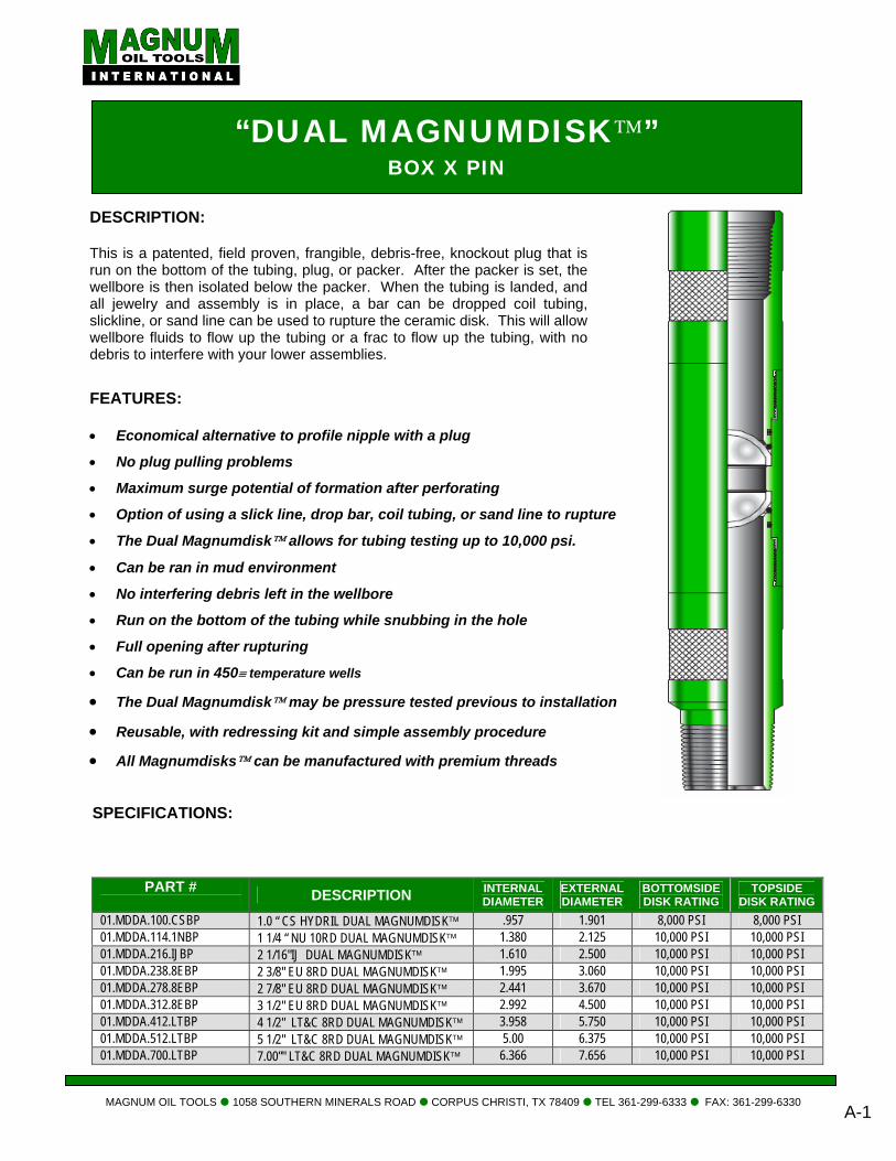
DESCRIPTION: This is a patented, field proven, frangible, debris-free, knockout plug that is run on the bottom of the tubing, plug, or packer. After the packer is set, the wellbore is then isolated below the packer. When the tubing is landed, and all jewelry and assembly is in place, a bar can be dropped coil tubing, slickline, or sand line can be used to rupture the ceramic disk. This will allow wellbore fluids to flow up the tubing or a frac to flow up the tubing, with no debris to interfere with your lower assemblies.
MAGNUM OIL TOOLS 1058 SOUTHERN MINERALS ROAD CORPUS CHRISTI, TX 78409 TEL 361-299-6333 FAX: 361-299-6330 A-1
SPECIFICATIONS:
FEATURES: • Economical alternative to profile nipple with a plug
• No plug pulling problems
• Maximum surge potential of formation after perforating
• Option of using a slick line, drop bar, coil tubing, or sand line to rupture
• The Dual Magnumdisk™ allows for tubing testing up to 10,000 psi.
• Can be ran in mud environment
• No interfering debris left in the wellbore
• Run on the bottom of the tubing while snubbing in the hole
• Full opening after rupturing
• Can be run in 450≡ temperature wells
• The Dual Magnumdisk™ may be pressure tested previous to installation
• Reusable, with redressing kit and simple assembly procedure
• All Magnumdisks™ can be manufactured with premium threads
PART # DESCRIPTION INTERNAL
DIAMETER EXTERNAL DIAMETER
BOTTOMSIDE DISK RATING
TOPSIDE DISK RATING
01.MDDA.100.CSBP 1.0 “ CS HYDRIL DUAL MAGNUMDISK™ .957 1.901 8,000 PSI 8,000 PSI 01.MDDA.114.1NBP 1 1/4 “ NU 10RD DUAL MAGNUMDISK™ 1.380 2.125 10,000 PSI 10,000 PSI 01.MDDA.216.IJBP 2 1/16"IJ DUAL MAGNUMDISK™ 1.610 2.500 10,000 PSI 10,000 PSI 01.MDDA.238.8EBP 2 3/8" EU 8RD DUAL MAGNUMDISK™ 1.995 3.060 10,000 PSI 10,000 PSI 01.MDDA.278.8EBP 2 7/8" EU 8RD DUAL MAGNUMDISK™ 2.441 3.670 10,000 PSI 10,000 PSI 01.MDDA.312.8EBP 3 1/2" EU 8RD DUAL MAGNUMDISK™ 2.992 4.500 10,000 PSI 10,000 PSI 01.MDDA.412.LTBP 4 1/2" LT&C 8RD DUAL MAGNUMDISK™ 3.958 5.750 10,000 PSI 10,000 PSI 01.MDDA.512.LTBP 5 1/2" LT&C 8RD DUAL MAGNUMDISK™ 5.00 6.375 10,000 PSI 10,000 PSI 01.MDDA.700.LTBP 7.00”" LT&C 8RD DUAL MAGNUMDISK™ 6.366 7.656 10,000 PSI 10,000 PSI
“DUAL MAGNUMDISK™” BOX X WIRELINE RE-ENTRY W/MULE SHOE
S
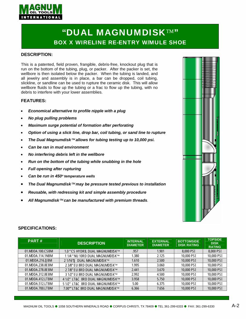
DESCRIPTION: This is a patented, field proven, frangible, debris-free, knockout plug that is run on the bottom of the tubing, plug, or packer. After the packer is set, the wellbore is then isolated below the packer. When the tubing is landed, and all jewelry and assembly is in place, a bar can be dropped, coil tubing, slickline, or sandline can be used to rupture the ceramic disk. This will allow wellbore fluids to flow up the tubing or a frac to flow up the tubing, with no debris to interfere with your lower assemblies.
MAGNUM OIL TOOLS 1058 SOUTHERN MINERALS ROAD CORPUS CHRISTI, TX 78409 TEL 361-299-6333 FAX: 361-299-6330
A-2
FEATURES: • Economical alternative to profile nipple with a plug
• No plug pulling problems
• Maximum surge potential of formation after perforating
• Option of using a slick line, drop bar, coil tubing, or sand line to rupture
• The Dual Magnumdisk™ allows for tubing testing up to 10,000 psi.
• Can be ran in mud environment
• No interfering debris left in the wellbore
• Run on the bottom of the tubing while snubbing in the hole
• Full opening after rupturing
• Can be run in 450º temperature wells
• The Dual Magnumdisk™ may be pressure tested previous to installation
• Reusable, with redressing kit and simple assembly procedure
• All Magnumdisk™ can be manufactured with premium threads.
PECIFICATIONS:
PART # DESCRIPTION INTERNAL
DIAMETER EXTERNAL DIAMETER
BOTTOMSIDE DISK RATING
TOPSIDE DISK
RATING 01.MDDA.100.CSBM 1.0 “ CS HYDRIL DUAL MAGNUMDISK™ .957 1.901 8,000 PSI 8,000 PSI 01.MDDA.114.1NBM 1 1/4 “ NU 10RD DUAL MAGNUMDISK™ 1.380 2.125 10,000 PSI 10,000 PSI 01.MDDA.216.IJBM 2 1/16"IJ DUAL MAGNUMDISK™ 1.610 2.500 10,000 PSI 10,000 PSI 01.MDDA.238.8EBM 2 3/8" EU 8RD DUAL MAGNUMDISK™ 1.995 3.060 10,000 PSI 10,000 PSI 01.MDDA.278.8EBM 2 7/8" EU 8RD DUAL MAGNUMDISK™ 2.441 3.670 10,000 PSI 10,000 PSI 01.MDDA.312.8EBM 3 1/2" EU 8RD DUAL MAGNUMDISK™ 2.992 4.500 10,000 PSI 10,000 PSI 01.MDDA.412.LTBM 4 1/2" LT&C 8RD DUAL MAGNUMDISK™ 3.958 5.750 10,000 PSI 10,000 PSI 01.MDDA.512.LTBM 5 1/2" LT&C 8RD DUAL MAGNUMDISK™ 5.00 6.375 10,000 PSI 10,000 PSI 01.MDDA.700.LTBM 7.00”" LT&C 8RD DUAL MAGNUMDISK™ 6.366 7.656 10,000 PSI 10,000 PSI
“SINGLE MAGNUMDISK™” BOX X PIN
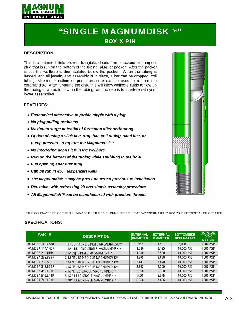
DESCRIPTION: This is a patented, field proven, frangible, debris-free, knockout or pumpout plug that is run on the bottom of the tubing, plug, or packer. After the packer is set, the wellbore is then isolated below the packer. When the tubing is landed, and all jewelry and assembly is in place, a bar can be dropped, coil tubing, slickline, sandline or pump pressure can be used to rupture the ceramic disk. After rupturing the disk, this will allow wellbore fluids to flow up the tubing or a frac to flow up the tubing, with no debris to interfere with your lower assemblies.
MAGNUM OIL TOOLS 1058 SOUTHERN MINERALS ROAD CORPUS CHRISTI, TX 78409 TEL 361-299-6333 FAX: 361-299-6330
A-3
*THE CONCAVE SIDE OF THE DISK MAY BE RUPTURED BY PUMP PRESSURE AT “APPROXIMATELY” 1000 PSI DIFFERENTIAL OR GREATER
SPECIFICATIONS:
PART # DESCRIPTION INTERNAL
DIAMETER EXTERNAL DIAMETER
BOTTOMSIDE DISK RATING
TOPSIDE DISK
RATING 01.MDSA.100.CSBP 1.0 “ CS HYDRIL SINGLE MAGNUMDISK™ .957 1.901 8,000 PSI 1,000 PSI* 01.MDSA.114.1NBP 1 1/4 “ NU 10RD SINGLE MAGNUMDISK™ 1.380 2.125 10,000 PSI 1,000 PSI* 01.MDSA.216.IJBP 2 1/16"IJ SINGLE MAGNUMDISK™ 1.610 2.500 10,000 PSI 1,000 PSI* 01.MDSA.238.8EBP 2 3/8" EU 8RD SINGLE MAGNUMDISK™ 1.995 3.060 10,000 PSI 1,000 PSI* 01.MDSA.278.8EBP 2 7/8" EU 8RD SINGLE MAGNUMDISK™ 2.441 3.670 10,000 PSI 1,000 PSI* 01.MDSA.312.8EBP 3 1/2" EU 8RD SINGLE MAGNUMDISK™ 2.992 4.500 10,000 PSI 1,000 PSI* 01.MDSA.412.LTBP 4 1/2" LT&C SINGLE MAGNUMDISK™ 3.958 5.750 10,000 PSI 1,000 PSI* 01.MDSA.512.LTBP 5 1/2" LT&C SINGLE MAGNUMDISK™ 5.00 6.375 10,000 PSI 1,000 PSI* 01.MDSA.700.LTBP 7.00”" LT&C SINGLE MAGNUMDISK™ 6.366 7.656 10,000 PSI 1,000 PSI*
FEATURES: • Economical alternative to profile nipple with a plug
• No plug pulling problems
• Maximum surge potential of formation after perforating
• Option of using a slick line, drop bar, coil tubing, sand line, or
pump pressure to rupture the Magnumdisk™
• No interfering debris left in the wellbore
• Run on the bottom of the tubing while snubbing in the hole
• Full opening after rupturing
• Can be run in 450º temperature wells
• The Magnumdisk™ may be pressure tested previous to installation
• Reusable, with redressing kit and simple assembly procedure
• All Magnumdisk™ can be manufactured with premium threads.
.
“SINGLE MAGNUMDISK™” BOX X WIRELINE RE-ENTRY W/MULE SHOE
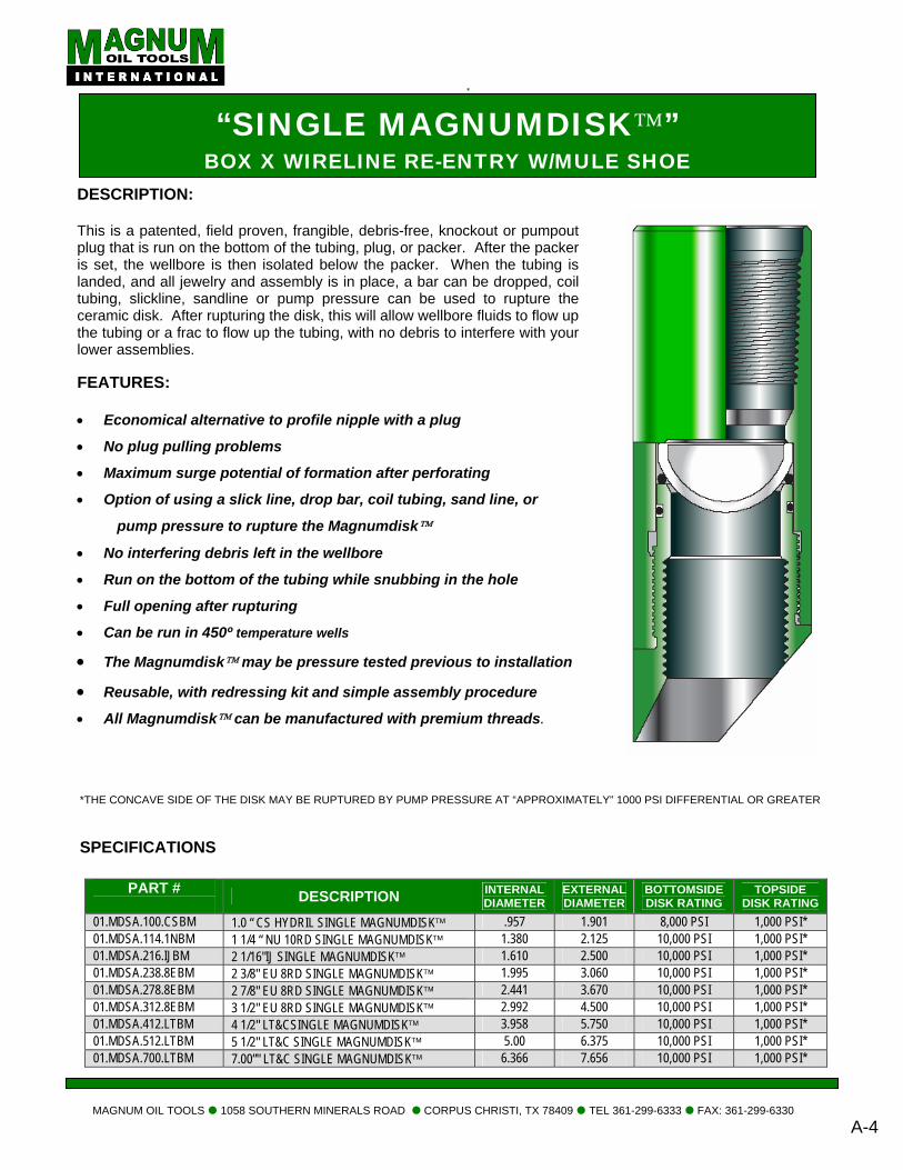
DESCRIPTION: This is a patented, field proven, frangible, debris-free, knockout or pumpout plug that is run on the bottom of the tubing, plug, or packer. After the packer is set, the wellbore is then isolated below the packer. When the tubing is landed, and all jewelry and assembly is in place, a bar can be dropped, coil tubing, slickline, sandline or pump pressure can be used to rupture the ceramic disk. After rupturing the disk, this will allow wellbore fluids to flow up the tubing or a frac to flow up the tubing, with no debris to interfere with your lower assemblies.
FEATURES: • Economical alternative to profile nipple with a plug
• No plug pulling problems
• Maximum surge potential of formation after perforating
• Option of using a slick line, drop bar, coil tubing, sand line, or
pump pressure to rupture the Magnumdisk™
• No interfering debris left in the wellbore
• Run on the bottom of the tubing while snubbing in the hole
• Full opening after rupturing
• Can be run in 450º temperature wells
• The Magnumdisk™ may be pressure tested previous to installation
• Reusable, with redressing kit and simple assembly procedure • All Magnumdisk™ can be manufactured with premium threads.
MAGNUM OIL TOOLS 1058 SOUTHERN MINERALS ROAD CORPUS CHRISTI, TX 78409 TEL 361-299-6333 FAX: 361-299-6330 A-4
*THE CONCAVE SIDE OF THE DISK MAY BE RUPTURED BY PUMP PRESSURE AT “APPROXIMATELY” 1000 PSI DIFFERENTIAL OR GREATER
SPECIFICATIONS
PART # DESCRIPTION INTERNAL
DIAMETER EXTERNAL DIAMETER
BOTTOMSIDE DISK RATING
TOPSIDE DISK RATING
01.MDSA.100.CSBM 1.0 “ CS HYDRIL SINGLE MAGNUMDISK™ .957 1.901 8,000 PSI 1,000 PSI* 01.MDSA.114.1NBM 1 1/4 “ NU 10RD SINGLE MAGNUMDISK™ 1.380 2.125 10,000 PSI 1,000 PSI* 01.MDSA.216.IJBM 2 1/16"IJ SINGLE MAGNUMDISK™ 1.610 2.500 10,000 PSI 1,000 PSI* 01.MDSA.238.8EBM 2 3/8" EU 8RD SINGLE MAGNUMDISK™ 1.995 3.060 10,000 PSI 1,000 PSI* 01.MDSA.278.8EBM 2 7/8" EU 8RD SINGLE MAGNUMDISK™ 2.441 3.670 10,000 PSI 1,000 PSI* 01.MDSA.312.8EBM 3 1/2" EU 8RD SINGLE MAGNUMDISK™ 2.992 4.500 10,000 PSI 1,000 PSI* 01.MDSA.412.LTBM 4 1/2" LT&CSINGLE MAGNUMDISK™ 3.958 5.750 10,000 PSI 1,000 PSI* 01.MDSA.512.LTBM 5 1/2" LT&C SINGLE MAGNUMDISK™ 5.00 6.375 10,000 PSI 1,000 PSI* 01.MDSA.700.LTBM 7.00”" LT&C SINGLE MAGNUMDISK™ 6.366 7.656 10,000 PSI 1,000 PSI*

“MAGNUMDISK™ REDRESS KIT” CERAMIC DISK REDRESS FOR SINGLE AND DUAL
DESCRIPTION: The Magnumdisk™ can be redressed after usage by utilizing the redress kit. The tool must be thoughly cleaned after retrieving from the well. The high impact ceramic disk can then be replaced in the housing and the o-ring greased and placed in the crush seal (spherical radius) area of the disk. Place the other o-ring on the nose of the body and tighten the tool.
FEATURES: • High impact ceramic construction
• Patented spherical design for maximum pressure rating
• Thin wall thickness
• Shatters into small crushable fragments
• Easily ruptured by impact
• Can be run in any environment and depth
• Can be run at any temperature up to 450º
• Full opening of Magnumdisk™ after rupturing
• Utilized with Single or Dual Magnumdisk™
• Pointed impact tool for more efficient rupturing
• Economical alternative to plugs in profile nipples
MAGNUM OIL TOOLS 1058 SOUTHERN MINERALS ROAD CORPUS CHRISTI, TX 78409 TEL 361-299-6333 FAX: 361-299-6330
A-5
*THE CONCAVE SIDE OF THE DISK MAY BE RUPTURED BY PUMP PRESSURE AT “APPROXIMATELY” 1000 PSI DIFFERENTIAL OR GREATER SPECIFICATIONS:
PART # DESCRIPTION INTERNAL
DIAMETER EXTERNAL DIAMETER
CONVEX SIDE DISK RATING
CONCAVE SIDE DISK RATING
01.MDRK.100.9999 MAGNUMDISK, REDRESS KIT, 1.00 “ .957 1.901 8,000 PSI 1,000 PSI* 01.MDRK.114.9999 MAGNUMDISK, REDRESS KIT, 1 ¼ “ 1.380 2.125 10,000 PSI 1,000 PSI* 01.MDRK.216.9999 MAGNUMDISK, REDRESS KIT, 2 1/16“ 1.610 2.500 10,000 PSI 1,000 PSI* 01.MDRK.238.9999 MAGNUMDISK, REDRESS KIT, 2 3/8“ 1.995 3.060 10,000 PSI 1,000 PSI* 01.MDRK.278.9999 MAGNUMDISK, REDRESS KIT, 2 7/8“ 2.441 3.670 10,000 PSI 1,000 PSI* 01.MDRK.312.9999 MAGNUMDISK, REDRESS KIT, 3 ½“ 2.992 4.500 10,000 PSI 1,000 PSI* 01.MDRK.412.9999 MAGNUMDISK, REDRESS KIT, 4 ½“ 3.958 5.750 10,000 PSI 1,000 PSI* 01.MDRK.512.9999 MAGNUMDISK, REDRESS KIT, 5 ½“ 5.00 6.375 10,000 PSI 1,000 PSI* 01.MDRK.700.9999 MAGNUMDISK, REDRESS KIT, 7“ 6.366 7.656 10,000 PSI 1,000 PSI*
“MAGNUMDISK™ TEST PLUG” FOR TESTING WIRELINE RE-ENTRY W/MULE SHOE
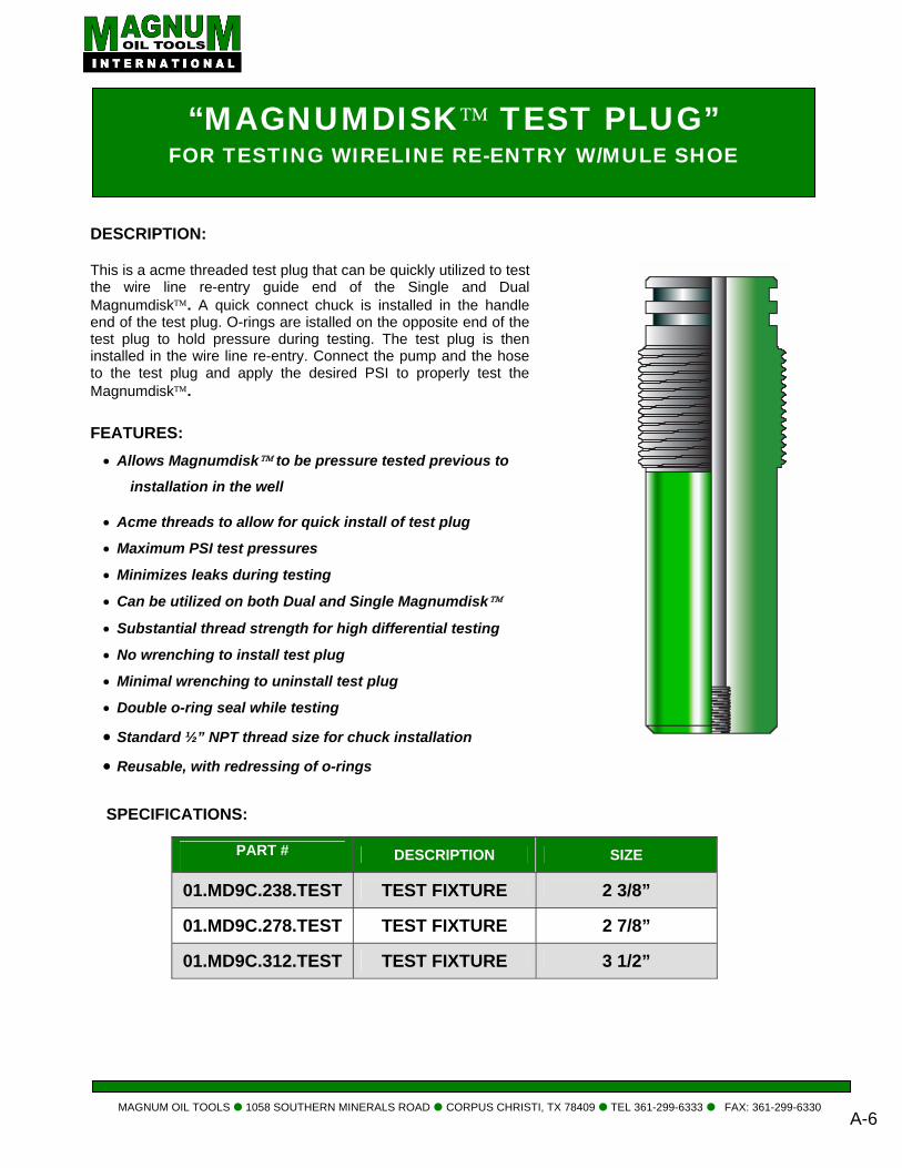
DESCRIPTION: This is a acme threaded test plug that can be quickly utilized to test the wire line re-entry guide end of the Single and Dual Magnumdisk™. A quick connect chuck is installed in the handle end of the test plug. O-rings are istalled on the opposite end of the test plug to hold pressure during testing. The test plug is then installed in the wire line re-entry. Connect the pump and the hose to the test plug and apply the desired PSI to properly test the Magnumdisk™.
MAGNUM OIL TOOLS 1058 SOUTHERN MINERALS ROAD CORPUS CHRISTI, TX 78409 TEL 361-299-6333 FAX: 361-299-6330
A-6
SPECIFICATIONS:
FEATURES: • Allows Magnumdisk™ to be pressure tested previous to
installation in the well
• Acme threads to allow for quick install of test plug
• Maximum PSI test pressures
• Minimizes leaks during testing
• Can be utilized on both Dual and Single Magnumdisk™
• Substantial thread strength for high differential testing
• No wrenching to install test plug
• Minimal wrenching to uninstall test plug
• Double o-ring seal while testing
• Standard ½” NPT thread size for chuck installation
• Reusable, with redressing of o-rings
PART #
DESCRIPTION SIZE
01.MD9C.238.TEST TEST FIXTURE 2 3/8”
01.MD9C.278.TEST TEST FIXTURE 2 7/8”
01.MD9C.312.TEST TEST FIXTURE 3 1/2”
“MAGNUMDISK™ GO-DEVIL” DROP BAR
DD
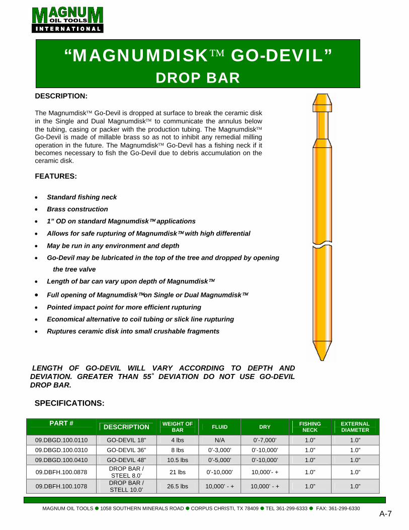
DESCRIPTION: The Magnumdisk™ Go-Devil is dropped at surface to break the ceramic disk in the Single and Dual Magnumdisk™ to communicate the annulus below the tubing, casing or packer with the production tubing. The Magnumdisk™ Go-Devil is made of millable brass so as not to inhibit any remedial milling operation in the future. The Magnumdisk™ Go-Devil has a fishing neck if it becomes necessary to fish the Go-Devil due to debris accumulation on the ceramic disk.
MAGNUM OIL TOOLS 1058 SOUTHERN MINERALS ROAD CORPUS CHRISTI, TX 78409 TEL 361-299-6333 FAX: 361-299-6330 A-7
LENGTH OF GO-DEVIL WILL VARY ACCORDING TO DEPTH AND EVIATION. GREATER THAN 55˚ DEVIATION DO NOT USE GO-DEVIL ROP BAR.
SPECIFICATIONS:
PART # DESCRIPTION WEIGHT OF
BAR FLUID DRY FISHING NECK
EXTERNAL DIAMETER
09.DBGD.100.0110 GO-DEVIL 18” 4 lbs N/A 0’-7,000’ 1.0” 1.0” 09.DBGD.100.0310 GO-DEVIL 36” 8 lbs 0’-3,000’ 0’-10,000’ 1.0” 1.0” 09.DBGD.100.0410 GO-DEVIL 48” 10.5 lbs 0’-5,000’ 0’-10,000’ 1.0” 1.0”
09.DBFH.100.0878 DROP BAR / STEEL 8.0’ 21 lbs 0’-10,000’ 10,000’- + 1.0” 1.0”
09.DBFH.100.1078 DROP BAR / STELL 10.0’ 26.5 lbs 10,000’ - + 10,000’ - + 1.0” 1.0”
FEATURES: • Standard fishing neck
• Brass construction
• 1” OD on standard Magnumdisk™ applications
• Allows for safe rupturing of Magnumdisk™ with high differential
• May be run in any environment and depth
• Go-Devil may be lubricated in the top of the tree and dropped by opening
the tree valve
• Length of bar can vary upon depth of Magnumdisk™
• Full opening of Magnumdisk™on Single or Dual Magnumdisk™ • Pointed impact point for more efficient rupturing
• Economical alternative to coil tubing or slick line rupturing
• Ruptures ceramic disk into small crushable fragments
“MX & MXN Nipple” PIN X PIN
DESCRIPTION: This is a universal landing nipple to achieve a degree of downhole selectivity. An operator can position as many nipples as desired to accomplish an unlimilted number of positions to optimize subsurface flow controls. This gives the operator options to manipulate the flow control up or down the well wherever another nipple is located, all by wireline under pressure without killing the well.
MAGNUM OIL TOOLS 1058 SOUTHERN MINERALS ROAD CORPUS CHRISTI, TX 78409 TEL 361-299-6333 FAX: 361-299-6330 A-8
SPECIFICATIONS:
MX & MXN PROFILE SIZE PART # TUBING O.D. MX MXN NO-GO ID
MX NIPPLE 08.MXXC.238.8EPP MXN NIPPLE 08.MXNC.238.8EPP
2.375 1.875 1.791
MX NIPPLE 08.MXXC.278.8EPP MXN NIPPLE 08.MXNC.278.8EPP
2.875 2.313 2.205
MX NIPPLE 08.MXXC.312.8EPP 2.875 N/A 2.760 MXN NIPPLE 08.MXNC.312.8EPP N/A 2.813 2.666 MXN NIPPLE 08.MXNC.313.8EPP
3.500 N/A 2.750 2.635
FEATURES: • Maximum versatility to reduce completion and production
maintenance costs
• Run in the tubing while snubbing in the hole
• Full opening after pulling locking mandrel
• All nipples can be manufactured with premium threads
• A large bore to permit maximum flow capacity
• Reusable universal nipples with one internal profile
B
PERFXTENDER PROPELLANT
PERFXTENDER™ DESCRIPTION: PerfXtender™ treatments utilize the deflagration of solid propellant to generate large volumes of high-pressure. The pressurized gas induces multiple fractures in the formation and increases formation permeability for improved reservoir communication and flow of hydrocarbons to the wellbore. The PerfXtender™ system provides a cost-effective, versatile, and efficient means of stimulating oil and gas wells by offering four sizes of propellant and tools for a large variety of applications. Magnum also offers an optional computer-modeling program that can be accessed by service company personnel to aid in the proper design of propellant stimulation treatments. APPLICATIONS: • Cleanout of casing perforations and mitigation of near-wellbore damage from
drilling, cementing, and perforating operations.
• Stimulation of mature wells where migration of fines, scaling, wax buildup, or other conditions have reduced near-wellbore permeability and well productivity.
• Formation breakdown treatments prior to hydraulic fracturing.
• Treatment of targeted intervals in vertical and horizontal wells to increase the effectiveness of subsequent fracturing operations.
• Increased injectivity in water injection wells to lower pumping costs in secondary recovery and water disposal applications.
• Stimulation of wells with productive formations in close proximity to potential water production.
OPERATION: The PerfXtender™ system can be conveyed into the wellbore on either wireline or tubing. It can be run in tandem with a perforating gun or as propellant alone for open holes or in wellbores where perforations already exist. The system comes in a variety of sizes and configurations for both through-tubing applications or for use in wells where the tubing has been pulled. Magnum’s modularized system allows the combination of multiple propellant grains for the effective treatment of virtually any productive interval thickness. The PerfXtender™ system has been designed for high reliability and ease of assembly by service company personnel.
MAGNUM OIL TOOLS 1058 SOUTHERN MINERALS ROAD CORPUS CHRISTI, TX 78409 TEL: 361-299-6333 FAX: 361-299-6330 B-1
PerfXtender™ Propellant System Introduction Magnum Oil Tools International, LLC is the manufacturer and patent holder of the PerfXtender™ line of solid propellant stimulation products. Magnum has applied its extensive experience in the design and manufacture of down-hole oilfield tools and systems to the creation of a safe and economic line of propellant products for the oil industry. PerfXtender™ products have been shown to be effective for use in the cleanout of casing perforations and mitigation of near-wellbore damage from drilling, cementing, and perforating operations. Our products have been extensively tested and utilized successfully in numerous well applications to date. Magnum and its distributors are offering the PerfXtender™ line of products to oilfield service companies as an addition to the current services that they provide, as well as an enhancement in the level of demand for their wireline and related services. The PerfXtender™ system can be conveyed into the wellbore on either wireline or tubing, and can be run in tandem with a perforating gun or as propellant alone for open holes or in wellbores where perforations already exist. The system comes in a variety of sizes and configurations for both through-tubing applications or in wells where the tubing has been pulled. Propellant Technology PerfXtender™ treatments employ the deflagration of solid propellant adjacent to a well’s productive interval. The resultant generation of large volumes of high-pressure gas over a short period of time induces fractures in the formation and increases formation permeability for improved communication and flow of hydrocarbons to the wellbore. Propellants that are suitable for use in formation stimulation must first exhibit physical properties that allow them to remain stable at the extreme temperatures and confining pressures encountered in many wellbores. Secondly, a suitable propellant must have a burn rate that accelerates predictably under these conditions and results in a pressure rise time that falls within defined limits for stimulation treatments to be effective. The peak pressures that are generated during the propellant event must exceed the tensile strength of the adjacent rock to initiate fracturing, yet remain below those pressures that will cause a failure of the rock in compression or possibly damage the wellbore. Lastly, produced gas volumes must also be sufficient to propagate fractures to a distance beyond the wellbore that is effective in improving a well’s production.
MAGNUM OIL TOOLS 1058 SOUTHERN MINERALS ROAD CORPUS CHRISTI, TX 78409 TEL: 361-299-6333 FAX: 361-299-6330
B-2
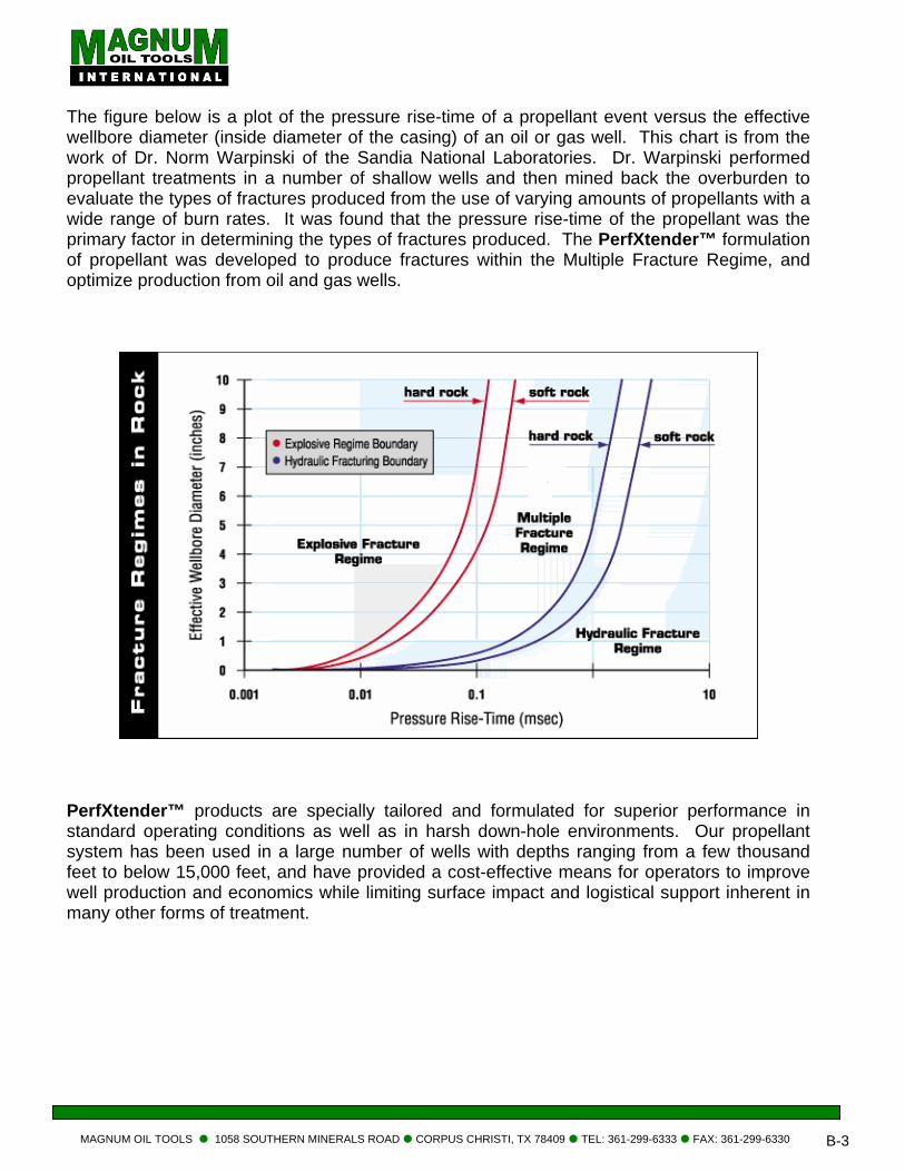
The figure below is a plot of the pressure rise-time of a propellant event versus the effective wellbore diameter (inside diameter of the casing) of an oil or gas well. This chart is from the work of Dr. Norm Warpinski of the Sandia National Laboratories. Dr. Warpinski performed propellant treatments in a number of shallow wells and then mined back the overburden to evaluate the types of fractures produced from the use of varying amounts of propellants with a wide range of burn rates. It was found that the pressure rise-time of the propellant was the primary factor in determining the types of fractures produced. The PerfXtender™ formulation of propellant was developed to produce fractures within the Multiple Fracture Regime, and optimize production from oil and gas wells.
PerfXtender™ products are specially tailored and formulated for superior performance in standard operating conditions as well as in harsh down-hole environments. Our propellant system has been used in a large number of wells with depths ranging from a few thousand feet to below 15,000 feet, and have provided a cost-effective means for operators to improve well production and economics while limiting surface impact and logistical support inherent in many other forms of treatment.
MAGNUM OIL TOOLS 1058 SOUTHERN MINERALS ROAD CORPUS CHRISTI, TX 78409 TEL: 361-299-6333 FAX: 361-299-6330
B-3
C
MILL-EZ™ COMPOSITEBRIDGE PLUGS
MAGNUM OIL TOOLS
DESCRIPTION: The “MAGNUM MBridge Plug. This Because of its low be quickly and easpatented bottom allwell bore. This madrilling with a rig an FEATURES: • Can be set on w • Utilizes convent • Multiple plugs in • Mill or drill mult • Can be milled or • Utilizes convent • Extremely fast m • High differential • Patented wash-t SPECIFICATION PART NUMBER
(“X” DENOTES PRESSURE AND TEMP
OF PLUG G,Y, OR B)
05.CBPA.238.175B
05.CBPA.278.220X
05.CBPA.278.220X
05.CBPA.312.273X
05.CBPA.31H.250X
05.CBPA.400.325X
05.CBPA.412.360X
05.CBPA.500.400X
05.CBPA.512.440X
05.CBPA.700.575X
05.CFBA.70L.595X
05.CBPA.758.640B
05.CBPA.858.713Y
05.CBPA.958.825Y
“MAGNUM MILL-EZ™”COMPOSITE BRIDGE PLUG
1058 SOUTHERN MINERALS ROAD CORPUS CHRISTI, TX 78409 TEL: 361-299-6333 FAX: 361-299-6330 C-1
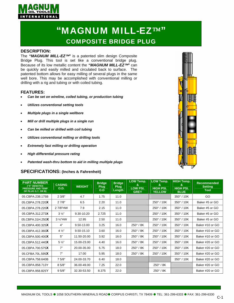
ILL-EZ™” is a patented slim design Composite tool is set like a conventional bridge plug.
metallic content the “MAGNUM MILL-EZ™” can ily milled and circulated back to surface. The
ows for easy milling of several plugs in the same y be accomplished with conventional milling or d tubing or with coiled tubing.
ireline, coiled tubing, or production tubing
ional setting tools
a single wellbore
iple plugs in a single run
drilled with coil tubing
ional milling or drilling tools
illing or drilling operation
pressure rating
hru bottom to aid in milling multiple plugs
S: (Inches & Fahrenheit)
CASING O.D. WEIGHT
Bridge Plug O.D
Bridge Plug
Length
LOW Temp. &
LOW PSI. GREY
LOW Temp. &
HIGH PSI. YELLOW
HIGH Temp. &
HIGH PSI. BLUE
Recommended Setting
Tool
2 3/8” 4.7 1.75 11.0 350° / 10K GO
2 7/8” 6.5 2.20 11.0 250° / 10K 350° / 10K Baker #5 or GO
2 7/8”HW 7.9 2.15 11.0 250° / 10K 350° / 10K Baker #5 or GO
3 ½” 9.30-10.20 2.725 11.0 250° / 10K 350° / 10K Baker #5 or GO
3 ½”HW 12.95 2.50 11.0 250° / 10K 350° / 10K Baker #5 or GO
4” 9.50-13.00 3.25 16.0 250° / 8K 250° / 10K 350° / 10K Baker #10 or GO
4 ½” 9.50-15.10 3.60 16.0 250° / 8K 250° / 10K 350° / 10K Baker #10 or GO 5” 11.50-20.00 3.92 16.0 250° / 8K 250° / 10K 350° / 10K Baker #10 or GO
5 ½” 15.00-23.00 4.40 16.0 250° / 8K 250° / 10K 350° / 10K Baker #20 or GO 7” 20.00-35.00 5.75 18.0 250° / 8K 250° / 10K 350° / 10K Baker #20 or GO 7” 17.00 5.95 18.0 250° / 8K 250° / 10K 350° / 10K Baker #20 or GO
7 5/8” 24.00-33.70 6.40 18.0 350° / 10K Baker #20 or GO
8 5/8” 36.00-49.00 7.25 22.0 250° / 8K Baker #20 or GO
9 5/8” 32.30-53.50 8.375 22.0 250° / 8K Baker #20 or GO
MAGNUM OIL TOOLS 1058 SOUTHERN MINERALS ROAD CORPUS CHRISTI, TX 78409 TEL: 361-299-6333 FAX: 361-299-6330 C-2
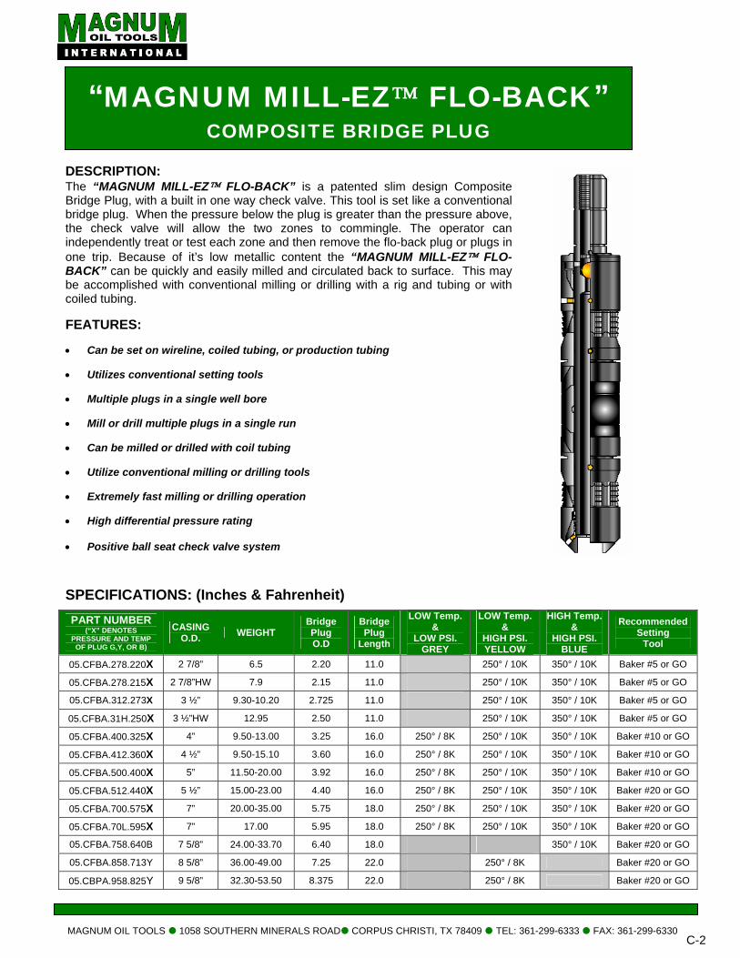
DESCRIPTION: The “MAGNUM MILL-EZ™ FLO-BACK” is a patented slim design Composite Bridge Plug, with a built in one way check valve. This tool is set like a conventional bridge plug. When the pressure below the plug is greater than the pressure above, the check valve will allow the two zones to commingle. The operator can independently treat or test each zone and then remove the flo-back plug or plugs in one trip. Because of it’s low metallic content the “MAGNUM MILL-EZ™ FLO-BACK” can be quickly and easily milled and circulated back to surface. This may be accomplished with conventional milling or drilling with a rig and tubing or with coiled tubing. FEATURES: • Can be set on wireline, coiled tubing, or production tubing • Utilizes conventional setting tools • Multiple plugs in a single well bore • Mill or drill multiple plugs in a single run • Can be milled or drilled with coil tubing • Utilize conventional milling or drilling tools • Extremely fast milling or drilling operation • High differential pressure rating • Positive ball seat check valve system SPECIFICATIONS: (Inches & Fahrenheit) PART NUMBER
(“X” DENOTES PRESSURE AND TEMP
OF PLUG G,Y, OR B)
CASING O.D. WEIGHT
Bridge Plug O.D
Bridge Plug
Length
LOW Temp. &
LOW PSI. GREY
LOW Temp. &
HIGH PSI. YELLOW
HIGH Temp. &
HIGH PSI. BLUE
Recommended Setting
Tool
05.CFBA.278.220X 2 7/8” 6.5 2.20 11.0 250° / 10K 350° / 10K Baker #5 or GO
05.CFBA.278.215X 2 7/8”HW 7.9 2.15 11.0 250° / 10K 350° / 10K Baker #5 or GO
05.CFBA.312.273X 3 ½” 9.30-10.20 2.725 11.0 250° / 10K 350° / 10K Baker #5 or GO
05.CFBA.31H.250X 3 ½”HW 12.95 2.50 11.0 250° / 10K 350° / 10K Baker #5 or GO
05.CFBA.400.325X 4” 9.50-13.00 3.25 16.0 250° / 8K 250° / 10K 350° / 10K Baker #10 or GO
05.CFBA.412.360X 4 ½” 9.50-15.10 3.60 16.0 250° / 8K 250° / 10K 350° / 10K Baker #10 or GO 05.CFBA.500.400X 5” 11.50-20.00 3.92 16.0 250° / 8K 250° / 10K 350° / 10K Baker #10 or GO 05.CFBA.512.440X 5 ½” 15.00-23.00 4.40 16.0 250° / 8K 250° / 10K 350° / 10K Baker #20 or GO 05.CFBA.700.575X 7” 20.00-35.00 5.75 18.0 250° / 8K 250° / 10K 350° / 10K Baker #20 or GO 05.CFBA.70L.595X 7” 17.00 5.95 18.0 250° / 8K 250° / 10K 350° / 10K Baker #20 or GO 05.CFBA.758.640B 7 5/8” 24.00-33.70 6.40 18.0 350° / 10K Baker #20 or GO
05.CFBA.858.713Y 8 5/8” 36.00-49.00 7.25 22.0 250° / 8K Baker #20 or GO
05.CBPA.958.825Y 9 5/8” 32.30-53.50 8.375 22.0 250° / 8K Baker #20 or GO
“MAGNUM MILL-EZ™ FLO-BACK” COMPOSITE BRIDGE PLUG
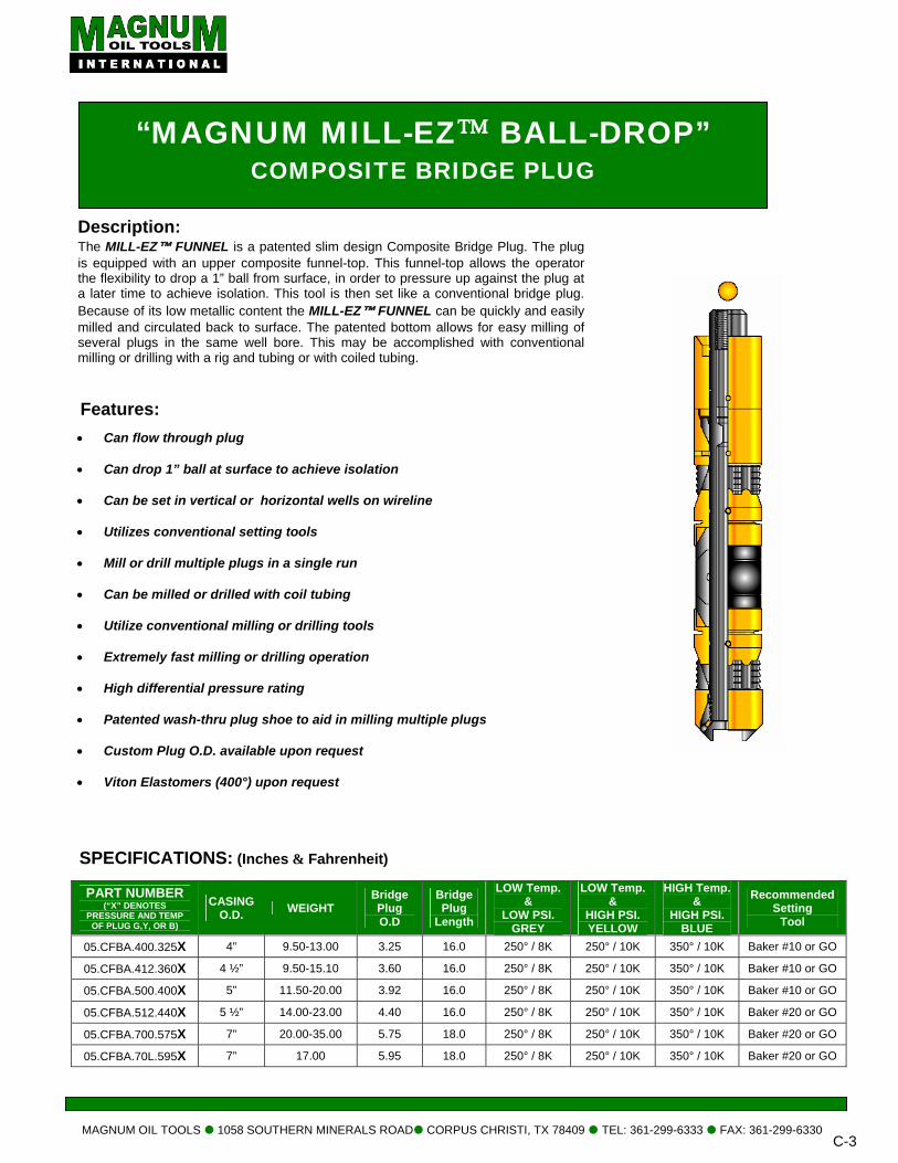
Description: The MILL-EZ™ FUNNEL is a patented slim design Composite Bridge Plug. The plug is equipped with an upper composite funnel-top. This funnel-top allows the operator the flexibility to drop a 1” ball from surface, in order to pressure up against the plug at a later time to achieve isolation. This tool is then set like a conventional bridge plug. Because of its low metallic content the MILL-EZ™ FUNNEL can be quickly and easily milled and circulated back to surface. The patented bottom allows for easy milling of several plugs in the same well bore. This may be accomplished with conventional milling or drilling with a rig and tubing or with coiled tubing.
“MAGNUM MILL-EZ™ BALL-DROP” COMPOSITE BRIDGE PLUG
Features: • Can flow through plug
• Can drop 1” ball at surface to achieve isolation
• Can be set in vertical or horizontal wells on wireline
• Utilizes conventional setting tools
• Mill or drill multiple plugs in a single run
• Can be milled or drilled with coil tubing
• Utilize conventional milling or drilling tools
• Extremely fast milling or drilling operation
• High differential pressure rating
• Patented wash-thru plug shoe to aid in milling multiple plugs
• Custom Plug O.D. available upon request
• Viton Elastomers (400°) upon request
MAGNUM OIL TOOLS 1058 SOUTHERN MINERALS ROAD CORPUS CHRISTI, TX 78409 TEL: 361-299-6333 FAX: 361-299-6330 C-3
SPECIFICATIONS: (Inches & Fahrenheit)
PART NUMBER (“X” DENOTES
PRESSURE AND TEMP OF PLUG G,Y, OR B)
CASING O.D. WEIGHT
Bridge Plug O.D
Bridge Plug
Length
LOW Temp. &
LOW PSI. GREY
LOW Temp. &
HIGH PSI. YELLOW
HIGH Temp. &
HIGH PSI. BLUE
Recommended Setting
Tool
05.CFBA.400.325X 4” 9.50-13.00 3.25 16.0 250° / 8K 250° / 10K 350° / 10K Baker #10 or GO
05.CFBA.412.360X 4 ½” 9.50-15.10 3.60 16.0 250° / 8K 250° / 10K 350° / 10K Baker #10 or GO 05.CFBA.500.400X 5” 11.50-20.00 3.92 16.0 250° / 8K 250° / 10K 350° / 10K Baker #10 or GO 05.CFBA.512.440X 5 ½” 14.00-23.00 4.40 16.0 250° / 8K 250° / 10K 350° / 10K Baker #20 or GO 05.CFBA.700.575X 7” 20.00-35.00 5.75 18.0 250° / 8K 250° / 10K 350° / 10K Baker #20 or GO 05.CFBA.70L.595X 7” 17.00 5.95 18.0 250° / 8K 250° / 10K 350° / 10K Baker #20 or GO
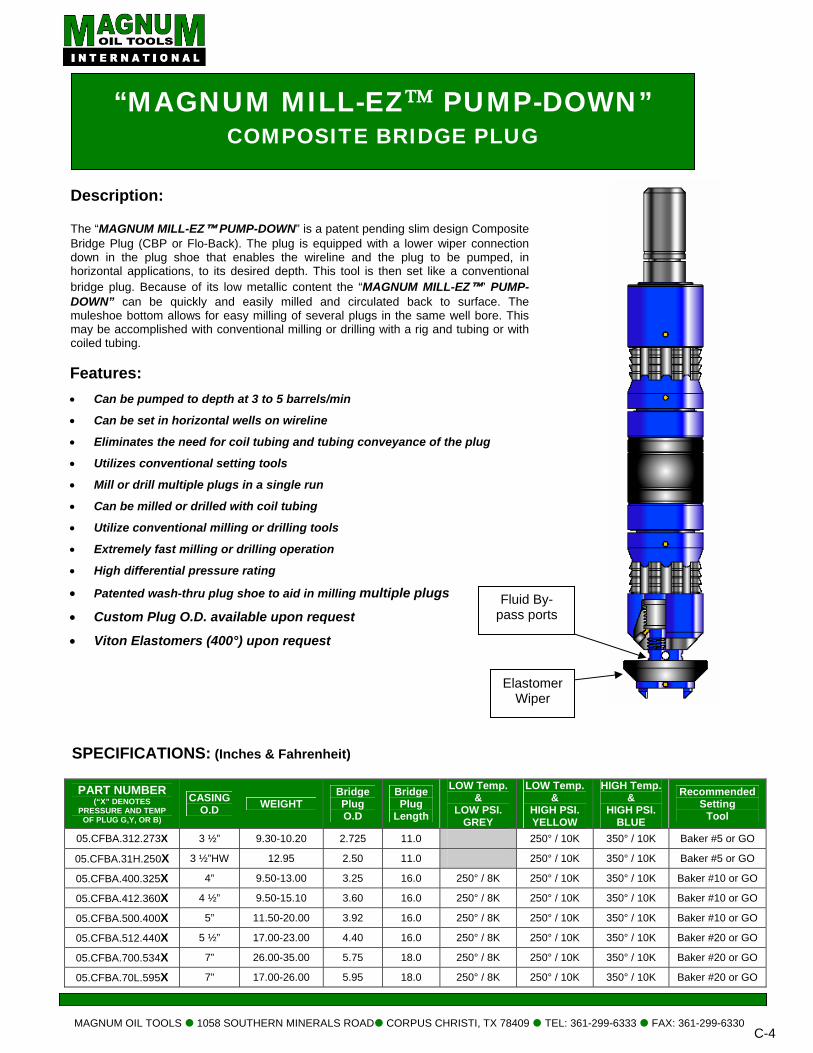
“MAGNUM MILL-EZ™ PUMP-DOWN” COMPOSITE BRIDGE PLUG
Description: The “MAGNUM MILL-EZ™ PUMP-DOWN” is a patent pending slim design Composite Bridge Plug (CBP or Flo-Back). The plug is equipped with a lower wiper connection down in the plug shoe that enables the wireline and the plug to be pumped, in horizontal applications, to its desired depth. This tool is then set like a conventional
PUMP-e. The e. This or with
Fluid By-pass ports
Features: • Can be pumped to depth at 3 to 5 barrels/min
• Can be set in horizontal wells on wireline
• Eliminates the need for coil tubing and tubing conveyance of the plug
• Utilizes conventional setting tools
• Mill or drill multiple plugs in a single run
• Can be milled or drilled with coil tubing
• Utilize conventional milling or drilling tools
• Extremely fast milling or drilling operation
• High differential pressure rating
• Patented wash-thru plug shoe to aid in milling multiple plugs
• Custom Plug O.D. available upon request
• Viton Elastomers (400°) upon request
bridge plug. Because of its low metallic content the “MAGNUM MILL-EZ™” DOWN” can be quickly and easily milled and circulated back to surfacmuleshoe bottom allows for easy milling of several plugs in the same well bormay be accomplished with conventional milling or drilling with a rig and tubing coiled tubing.
MAGNUM OIL TOOLS 1058 SOUTHERN MINERALS ROAD CORPUS CHRISTI, TX 78409 TEL: 361-299-6333 FAX: 361-299-6330 C-4
SPECIFICATIONS: (Inches & Fahrenheit)
PART NUMBER (“X” DENOTES
PRESSURE AND TEMP OF PLUG G,Y, OR B)
CASING O.D WEIGHT
Bridge Plug O.D
Bridge Plug
Length
LOW Temp. &
LOW PSI. GREY
LOW Temp. &
HIGH PSI. YELLOW
HIGH Temp. &
HIGH PSI. BLUE
Recommended Setting
Tool
05.CFBA.312.273X 3 ½” 9.30-10.20 2.725 11.0 250° / 10K 350° / 10K Baker #5 or GO
05.CFBA.31H.250X 3 ½”HW 12.95 2.50 11.0 250° / 10K 350° / 10K Baker #5 or GO
05.CFBA.400.325X 4” 9.50-13.00 3.25 16.0 250° / 8K 250° / 10K 350° / 10K Baker #10 or GO
05.CFBA.412.360X 4 ½” 9.50-15.10 3.60 16.0 250° / 8K 250° / 10K 350° / 10K Baker #10 or GO 05.CFBA.500.400X 5” 11.50-20.00 3.92 16.0 250° / 8K 250° / 10K 350° / 10K Baker #10 or GO 05.CFBA.512.440X 5 ½” 17.00-23.00 4.40 16.0 250° / 8K 250° / 10K 350° / 10K Baker #20 or GO 05.CFBA.700.534X 7” 26.00-35.00 5.75 18.0 250° / 8K 250° / 10K 350° / 10K Baker #20 or GO 05.CFBA.70L.595X 7” 17.00-26.00 5.95 18.0 250° / 8K 250° / 10K 350° / 10K Baker #20 or GO
Elastomer Wiper
MAGNUM OIL TOOLS 1058 SOUTHERN MINERALS ROAD CORPUS CHRISTI, TX 78409 TEL: 361-299-6333 FAX: 361-299-6330 C-5
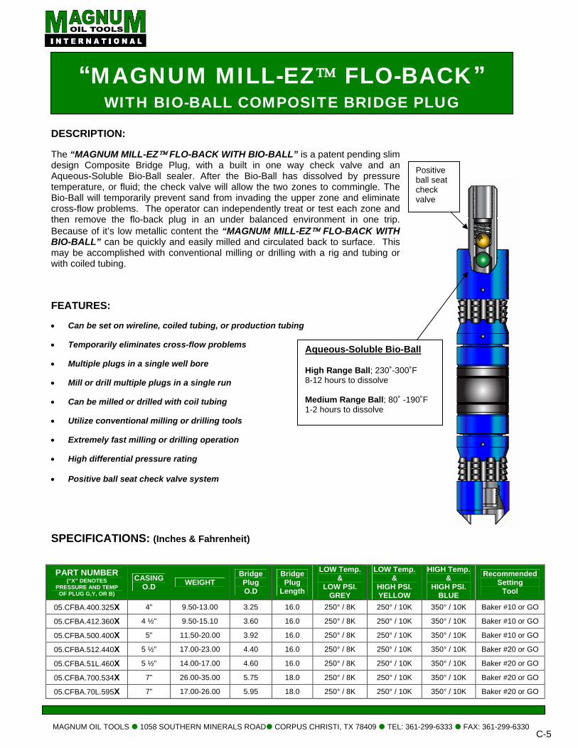
DESCRIPTION: The “MAGNUM MILL-EZ™ FLO-BACK WITH BIO-BALL” is a patent pending slim design Composite Bridge Plug, with a built in one way check valve and an Aqueous-Soluble Bio-Ball sealer. After the Bio-Ball has dissolved by pressure temperature, or fluid; the check valve will allow the two zones to commingle. The Bio-Ball will temporarily prevent sand from invading the upper zone and eliminate cross-flow problems. The operator can independently treat or test each zone and then remove the flo-back plug in an under balanced environment in one trip. Because of it’s low metallic content the “MAGNUM MILL-EZ™ FLO-BACK WITH BIO-BALL” can be quickly and easily milled and circulated back to surface. This may be accomplished with conventional milling or drilling with a rig and tubing or with coiled tubing. FEATURES: • Can be set on wireline, coiled tubing, or production tubing • Temporarily eliminates cross-flow problems • Multiple plugs in a single well bore • Mill or drill multiple plugs in a single run • Can be milled or drilled with coil tubing • Utilize conventional milling or drilling tools • Extremely fast milling or drilling operation • High differential pressure rating • Positive ball seat check valve system
SPECIFICATIONS: (Inches & Fahrenheit)
PART NUMBER (“X” DENOTES
PRESSURE AND TEMP OF PLUG G,Y, OR B)
CASING O.D WEIGHT
Bridge Plug O.D
Bridge Plug
Length
LOW Temp. &
LOW PSI. GREY
LOW Temp. &
HIGH PSI. YELLOW
HIGH Temp. &
HIGH PSI. BLUE
Recommended Setting
Tool
05.CFBA.400.325X 4” 9.50-13.00 3.25 16.0 250° / 8K 250° / 10K 350° / 10K Baker #10 or GO
05.CFBA.412.360X 4 ½” 9.50-15.10 3.60 16.0 250° / 8K 250° / 10K 350° / 10K Baker #10 or GO 05.CFBA.500.400X 5” 11.50-20.00 3.92 16.0 250° / 8K 250° / 10K 350° / 10K Baker #10 or GO 05.CFBA.512.440X 5 ½” 17.00-23.00 4.40 16.0 250° / 8K 250° / 10K 350° / 10K Baker #20 or GO 05.CFBA.51L.460X 5 ½” 14.00-17.00 4.60 16.0 250° / 8K 250° / 10K 350° / 10K Baker #20 or GO 05.CFBA.700.534X 7” 26.00-35.00 5.75 18.0 250° / 8K 250° / 10K 350° / 10K Baker #20 or GO 05.CFBA.70L.595X 7” 17.00-26.00 5.95 18.0 250° / 8K 250° / 10K 350° / 10K Baker #20 or GO
Positive ball seat check valve
Aqueous-Soluble Bio-Ball High Range Ball; 230˚-300˚F 8-12 hours to dissolve Medium Range Ball; 80˚ -190˚F 1-2 hours to dissolve
“MAGNUM MILL-EZ™ FLO-BACK” WITH BIO-BALL COMPOSITE BRIDGE PLUG
MAGNUM OIL TOOLS 1058 SOUTHERN MINERALS ROAD CORPUS CHRISTI, TX 78409 TEL: 361-299-6333 FAX: 361-299-6330 C-6
Installation of the Mill-EZ™ 2 3/8”, 2 7/8”, 3 ½” MILL-EZ™ Composite Bridge Plug Prior to running a Mill-EZ™ 2 3/8”, 2 7/8”, or 3 ½” Mill-EZ™ Composite Bridge Plug on wireline, a wireline gauge ring larger than the OD of the plug and less than the drift of the casing should be ran. A depth of greater than the setting depth of the bridge plug is desired. If any obstruction is encountered in the casing, additional gauge ring runs should be made to recover obstruction or an alternate casing cleanup process considered. Load the Baker wireline setting tool with the appropriate amount of oil according to the temperature at the Plug’s setting depth. Always use a Baker Slow Set Power Charge in the setting tool. Make sure all connections on the setting tool are tight. Next, screw the adapter mandrel into the setting tool inner mandrel. Use a small pipe wrench when tightening the adapter mandrel into the inner mandrel. Slightly more than hand tightened is sufficient. This will prevent the adapter mandrel from falling into the well bore if the adapter mandrel should back out while coming out of the hole. Tighten the 2 3/8”, 2 7/8”, or 3 ½” Mill-EZ™ setting sleeve onto the setting tool to the jam nut, while holding the setting tool. Guide the bridge plug mandrel into the setting sleeve and onto the adapter mandrel. Rotate clockwise until the mandrel threads are fully engage. It is not necessary to use a pipe wrench when tightening the adapter mandrel onto the plug. Firmly hand tightened is sufficient. Rotate the setting sleeve toward the plug until it has come into contact with the push ring on the top of the bridge plug; continue to rotate the assembly to the right until any air gap on the setting tools sleeve is eliminated. If the air gap cannot be eliminated without using a pipe wrench on the plug, the setting tool should be disassembled and inspected. Then rotate the jam nut down to the setting sleeve and tighten the jam nut to the setting sleeve with a pipe wrench. NOTE: hand tight is sufficient. Running the 2 3/8”, 2 7/8”, 3 ½” MILL–EZ Bridge Plug in the well Once the length of the CCL to the top of the plug has been determined. Pick up the setting tool and 2 3/8”, 2 7/8”, or 3 ½” Mill-EZ™ Bridge plug assembly with wire line. NOTE: For best results, DO NOT support the weight of the setting tool, CCL, and bridge plug by the bridge plug. Support the weight by handling the setting tool itself. Precaution should be used once the assembly is suspended as to not let the plug swing into valves or pressure lines thus causing damage or injury to the plug and employees. When running the plug in the well, a line speed of 200’ to 250’ per minute is desirable. Certain conditions may warrant a less rapid descent or an increased rate of speed. NOTE: Hitting fluid level or a sand bridge at a rapid speed will prematurely set the bridge plug! Once the setting depth is achieved, set the plug and note any weight loss of the assembly on the wire line trucks weight indicator. In some cases there may not be a positive indication that the plug is set. Pick up the setting assembly approx. 20’ to 30’. Lower the assembly onto the plug noting any weight loss or CCL movement. Pull the setting assembly out of the hole. If the fluid level is anything other than full, a slow line speed is desired when leaving fluid to air. Lay down the setting assembly and bleed of the trapped pressure in the setting tool. *Ample cement or sand should be used on the top of the plug to absorb the percussion generated by the perforating guns. *Do not perforate within 75’ of the plug after it is set. Disassembling the setting equipment from the setting tool. Holding back-ups on the setting tool rotate the setting sleeve and remove. Remove the adapter mandrel from the setting tool mandrel. CAUTION: When testing the plug slowly fill hole with fluid so as not to hammer the plug down the hole with the column of fluid. Recommended pump rate is ¼ to ½ bbl/min for the first 30 minutes to ensure a sufficient fluid cushion.
MAGNUM OIL TOOLS 1058 SOUTHERN MINERALS ROAD CORPUS CHRISTI, TX 78409 TEL: 361-299-6333 FAX: 361-299-6330 C-7
Installation of the Mill-EZ™ 4”, 4 ½”, 5” MILL-EZ™ Composite Bridge Plug Prior to running a Mill-EZ™ Model 4”, 4 ½”, 5”, MILL-EZ™ Composite Bridge Plug on wireline, a wireline gauge ring larger than the OD of the plug and less than the drift of the casing should be ran. A depth of greater than the setting depth of the bridge plug is desired. If any obstruction is encountered in the casing, additional gauge ring runs should be made to recover obstruction or an alternate casing cleanup process considered. Load the Baker wireline setting tool with the appropriate amount of oil according to the temperature at the Plug’s setting depth. Always use a Baker Slow Set Power Charge in the setting tool. Make sure all connections on the setting tool are tight. Tighten the 4”, 4 ½”, or 5” Mill-EZ™ setting sleeve onto the setting tool with a pipe wrench, while holding a backup on the setting tool. With the plug upright, screw the adapter mandrel onto the upper threads of the plug mandrel. NOTE: It is necessary to use a small pipe wrench with light pressure, when tightening the adapter mandrel onto the plug. Back the plug up above the shear area, close to the end of the plug, so as not to turn thru the shear point. Install the Lock Spring provided with each plug, onto the upper portion of the adapter mandrel until the spring is flush with the top of the threads. Align the slot on the setting tool with the tattletale of the spring. Holding the plug from the bottom sub, rotate the entire assembly to the right. Once the setting sleeve has come into contact with the push ring of the plug, continue to rotate the assembly to the right until any air gap on the setting tools sleeve is eliminated. If the air gap cannot be eliminated without using a pipe wrench on the plug, the setting tool should be disassembled and inspected. NOTE: hand tight is sufficient, the lock spring will eliminate the possibility of the plug backing off during the run-in and setting process. Running the 4”, 4 ½”, 5” MILL–EZ Bridge Plug in the well Once the length of the CCL to the top of the plug has been determined. (Approx. 8 feet)
Pick up the setting tool and Model 4”, 4 ½”, 5” Mill-EZ™ Bridge plug assembly with wireline. NOTE: For best results, do not support the weight of the setting tool, CCL and bridge plug by the bridge plug. Support the weight by handling the setting tool itself. Precaution should be used once the assembly is suspended as to not let the plug swing into valves or pressure lines thus causing damage or injury to the plug and employees. When running the plug in the well, a line speed of 250’ to 300’ per minute is desirable. Certain conditions may warrant a less rapid descent or an increased rate of speed. NOTE: Hitting fluid level or sand bridge at a rapid speed will prematurely set the bridge plug! Once the setting depth is achieved, set the plug and note any weight loss of the assembly on the wireline trucks weight indicator. In some cases there may not be a positive indication that the plug is set. Pick up the setting assembly approx. 20’ to 30’. Lower the assembly onto the plug noting any weight loss or CCL movement. Pull the setting assembly out of the hole. If the fluid level is anything other than full, a slow line speed is desired when leaving fluid to air. Lay down the setting assembly and bleed of the trapped pressure in the setting tool. *Ample cement or sand should be used on the top of the plug to absorb the percussion generated by the perforating guns. *Do not perforate within 75’ of the plug after it is set. Disassembling the setting equipment from the setting tool. Holding back-ups on the setting tool rotate the setting sleeve loose. Insert a rod through the setting sleeve and the adapter mandrel. Rotate both at the same time to unscrew the adapter mandrel from the setting tool. Remove the adapter mandrel from the inside of the setting sleeve. CAUTION: When testing the plug slowly fill hole with fluid so as not to hammer the plug down the hole with the column of fluid. Recommended pump rate is ¼ to ½ bbl/min for the first 30 minutes to ensure a sufficient fluid cushion.
MAGNUM OIL TOOLS 1058 SOUTHERN MINERALS ROAD CORPUS CHRISTI, TX 78409 TEL: 361-299-6333 FAX: 361-299-6330 C-8
Installation of the Mill-EZ™ 5 ½”, 7”, 7 5/8”, 8 5/8” or 9 5/8” MILL-EZ™ Composite Bridge Plug Prior to running a Mill-EZ™ 5 ½”, 7”, 7 5/8” or 9 5/8” Mill-EZ™ Composite Bridge Plug on wireline, a wireline gauge ring larger than the OD of the plug and less than the drift of the casing should be ran. A depth of greater than the setting depth of the bridge plug is desired. If any obstruction is encountered in the casing, additional gauge ring runs should be made to recover obstruction or an alternate casing cleanup process considered. Load the Baker wireline setting tool with the appropriate amount of oil according to the temperature at the Plug’s setting depth. Always use a Baker Slow Set Power Charge in the setting tool. Make sure all connections on the setting tool are tight. Tighten the 5 ½”, 7”, 7 5/8” or 9 5/8” Mill-EZ™ setting sleeve onto the setting tool with a pipe wrench, while holding a backup on the setting tool. With the plug upright, screw the adapter mandrel onto the upper threads of the plug mandrel. NOTE: It is necessary to use a small pipe wrench with light pressure, when tightening the adapter mandrel onto the plug. Back the plug up above the shear area, close to the end of the plug, so as not to turn thru the shear point. Install the Lock Spring provided with each plug onto the upper portion of the adapter mandrel until the spring is flush with the top of the threads. Align the slot on the setting tool with the tattletale of the spring. Holding the plug from the bottom sub, rotate the entire assembly to the right. Once the setting sleeve has come into contact with the top of the plug, continue to rotate the assembly to the right until any air gap on the setting tools sleeve is eliminated. If the air gap cannot be eliminated without using a pipe wrench on the plug, the setting tool should be disassembled and inspected. NOTE: Hand tight is sufficient, the lock spring will eliminate the possibility of the plug backing off during the run-in and setting process. Running the 5 ½”, 7”, 7 5/8”, 8 5/8” or 9 5/8” MILL–EZ™ Bridge Plug in the well Once the length of the CCL to the top of the plug has been determined. (Approx. 8 feet) Pick up the setting tool and Model 5 ½”, 7”, 7 5/8” or 9 5/8” Mill-EZ™ Bridge plug assembly with wireline. NOTE: For best results, do not support the weight of the setting tool, CCL and bridge plug by the bridge plug. Support the weight by handling the setting tool itself. Precaution should be used once the assembly is suspended as to not let the plug swing into valves or pressure lines thus causing damage or injury to the plug and employees. When running the plug in the well, a line speed of 250’ to 300’ per minute is desirable. Certain conditions may warrant a less rapid descent or an increased rate of speed. NOTE: Hitting fluid level or sand bridge at a rapid speed will prematurely set the bridge plug. Once the setting depth is achieved, set the plug and note any weight loss of the assembly on the wireline truck weight indicator. In some cases there may not be a positive indication that the plug is set. Pick up the setting assembly approx. 20’ to 30’. Lower the assembly onto the plug noting any weight loss or CCL movement. Pull the setting assembly out of the hole. Lay down the setting assembly and bleed of the trapped pressure in the setting tool. *Ample cement or sand should be used on the top of the plug to absorb the percussion generated by the perforating guns. *Do not perforate within 75’ of the plug after it is set. Disassembling the setting equipment from the setting tool. Holding back-ups on the setting tool rotate the setting sleeve loose. Unscrew the adapter mandrel from the setting tool. Remove the spring from the adapter mandrel. CAUTION: When testing the plug slowly fill the hole with fluid so as not to hammer the plug down the hole with the column of fluid. Recommended pump rate is ¼ to ½ bbl/min for the first 30 minutes to ensure a sufficient fluid cushion.
MAGNUM OIL TOOLS 1058 SOUTHERN MINERALS ROAD CORPUS CHRISTI, TX 78409 TEL: 361-299-6333 FAX: 361-299-6330 C-9
Recommended Coiled Tubing Drilling/Milling Procedures For The Mill-EZ™ Composite Plugs
The following Bottom Hole Assembly is recommended to remove the Mill-EZ™ Composite Bridge Plug/Flow-Back Plug. There are multiple variables to consider when drilling out composite plugs and the following procedures have produced the best results.
• 6 Bladed Magnum Mill (95-98% of Drift Diameter) • Hi Torque Mud Motor • Hydraulic Disconnect • Dual Back Pressure Valve • Coiled Tubing Connector • Enough Coil Tubing to reach bottom of well
The following is a recommended drilling/milling procedure for removing and eliminating one or multiple Mill-EZ™ Composite Bridge Plugs from the well bore. Check to ensure all equipment is compatible and all running procedures are well within manufactures recommended guidelines.
1. Move in Coiled Tubing Equipment (It is recommended to have a Double Pump Truck spot the equipment.
2. Have a safety briefing to cover the rig up procedures 3. Rig up Coiled Tubing Equipment and enough lubricator to cover the bottom hole assembly, motor and
the Magnum Mill. 4. Function test the BOP’s with the coiled tubing crew. 5. Run Coil Tubing through the coiled tubing stack until pipe comes out of the lubricator. 6. Mic the coiled tubing to ensure the correct O.D. and no egg-shaping of the coiled tubing. 7. Straighten the coil and cut the bottom of the coil off. File the flared end of the coil to bevel the end of
it. (This helps from cutting o-rings and damaging slips when making up the coil). 8. Make up the coil connector with a pull tester plate. Pull test the coil connector to manufactures
recommended pull weight. NOTE: When pull testing the coil connector measure off the hydraulics, then compare it to the weight indicator to adjust the weight indicator if it is off.
9. Run the coil out of the lubricator and check the make on the coil. Retighten the coil connector and make up the set screws.
10. Load and circulate the coiled tubing with fluid until the fluid comes out clean. NOTE: Recommended to run in line filter with a screen.
11. Make up the dual back pressure valve, hydraulic release, and hi-torque motor with the Magnum Mill. Test the motor at surface by drilling a test hole.
12. Rig up on the well and test. 13. Run in the hole, pumping through the motor at the minimum rate checking pick up and run in weights. 14. Approximately 1,000’ before the perfs bring the pump rate up on the motor to the manufactures
recommended rate (approx 400 to 600 rpm). 15. Pump a dyed gel sweep. 16. Approximately 100’ before the perfs depth establish the flow rate in the return tank. The optimum rate
is bbl in bbl out. NOTE: The bbl for bbl rate will also depend on the pressures below the plug from the pressures from the open perfs. This will determine on how much back pressure to hold. If there is a possibility of drilling through higher a differential (after running the coil through the perfs, while staying off the plug) it would be necessary to clean out the well bore before drilling out the plug, this will eliminate the possibilities of sticking the coil.
MAGNUM OIL TOOLS 1058 SOUTHERN MINERALS ROAD CORPUS CHRISTI, TX 78409 TEL: 361-299-6333 FAX: 361-299-6330 C-10
17. After the rates and wellbore differentials are stable, run in the hole no more than 5 ft/min. watching
the weight indicator. When you see about 200lbs to 500lbs of weight loss, let the coiled unit creep in the hole about .1 to .3 ft/min. watching for any pump pressure increases or continuation of weight loss. (No more than 1,000lbs). Once you see the pump pressure increase 100lbs to 300lbs differential, set the brake to gain weight back to normal pump pressure. Release brake continuing the milling operations until string weight and pump pressure is regained (if you are taking a gas kick, it is recommended to pick up above the perfs and circulate the well until the pump rate and wellhead pressure is maintained and the weight on the coil is ok).
18. After the plug has been milled through, pump 10bbl gel sweep with dye pumping 5bbl gel and 5bbl KCL water, then 5bbl gel and continue to the desired depth.
19. For multiple plugs, continue drill-out procedures form step 14 NOTE: Each stage will have different bottom hole pressures which will determine on what needs to be held on the backside. Pumping gel sweeps before and after drilling the plug and circulating well clean before each stage will help from sticking the coiled tubing.
NOTE: It is preferred to take a less aggressive approach and mill or grind the plug into small
pieces to minimize debris size for particle managing reason.
MAGNUM OIL TOOLS 1058 SOUTHERN MINERALS ROAD CORPUS CHRISTI, TX 78409 TEL: 361-299-6333 FAX: 361-299-6330 C-11
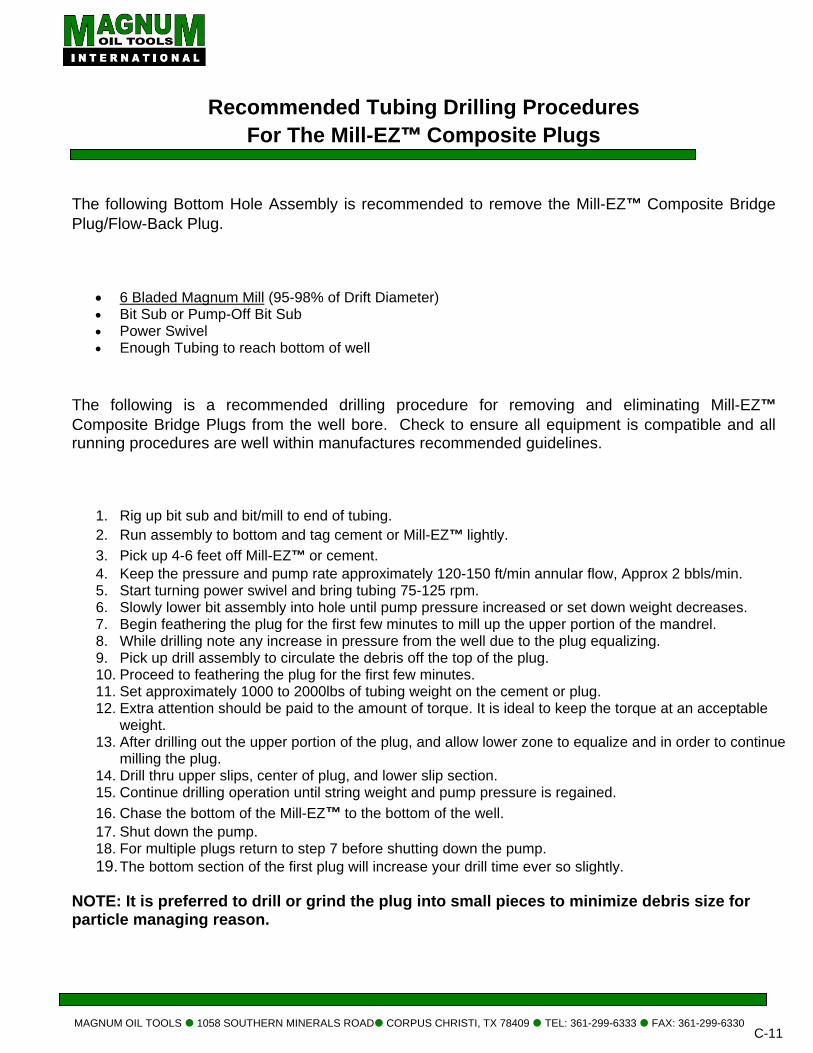
Recommended Tubing Drilling Procedures
For The Mill-EZ™ Composite Plugs
The following Bottom Hole Assembly is recommended to remove the Mill-EZ™ Composite Bridge Plug/Flow-Back Plug.
• 6 Bladed Magnum Mill (95-98% of Drift Diameter) • Bit Sub or Pump-Off Bit Sub • Power Swivel • Enough Tubing to reach bottom of well
The following is a recommended drilling procedure for removing and eliminating Mill-EZ™ Composite Bridge Plugs from the well bore. Check to ensure all equipment is compatible and all running procedures are well within manufactures recommended guidelines.
1. Rig up bit sub and bit/mill to end of tubing. 2. Run assembly to bottom and tag cement or Mill-EZ™ lightly. 3. Pick up 4-6 feet off Mill-EZ™ or cement. 4. Keep the pressure and pump rate approximately 120-150 ft/min annular flow, Approx 2 bbls/min. 5. Start turning power swivel and bring tubing 75-125 rpm. 6. Slowly lower bit assembly into hole until pump pressure increased or set down weight decreases. 7. Begin feathering the plug for the first few minutes to mill up the upper portion of the mandrel. 8. While drilling note any increase in pressure from the well due to the plug equalizing. 9. Pick up drill assembly to circulate the debris off the top of the plug. 10. Proceed to feathering the plug for the first few minutes. 11. Set approximately 1000 to 2000lbs of tubing weight on the cement or plug. 12. Extra attention should be paid to the amount of torque. It is ideal to keep the torque at an acceptable
weight. 13. After drilling out the upper portion of the plug, and allow lower zone to equalize and in order to continue
milling the plug. 14. Drill thru upper slips, center of plug, and lower slip section. 15. Continue drilling operation until string weight and pump pressure is regained. 16. Chase the bottom of the Mill-EZ™ to the bottom of the well. 17. Shut down the pump. 18. For multiple plugs return to step 7 before shutting down the pump. 19. The bottom section of the first plug will increase your drill time ever so slightly.
NOTE: It is preferred to drill or grind the plug into small pieces to minimize debris size for particle managing reason.
MAGNUM OIL TOOLS 1058 SOUTHERN MINERALS ROAD CORPUS CHRISTI, TX 78409 TEL: 361-299-6333 FAX: 361-299-6330 C-12
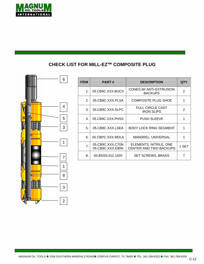
CHECK LIST FOR MILL-EZ™ COMPOSITE PLUG
ITEM PART # DESCRIPTION QTY
1. 05.CB9C.XXX.BUCX CONES,W/ ANTI-EXTRUSION BACKUPS 2
2. 05.CB9C.XXX.PLSA COMPOSITE PLUG SHOE 1
3. 05.CB9C.XXX.SLPC FULL CIRCLE CAST IRON SLIPS 2
4. 05.CB9C.XXX.PHSX PUSH SLEEVE 1
5. 05.CB9C.XXX.LSEA BODY LOCK RING SEGMENT 1
6. 05.CBPC.XXX.MDLA MANDREL, UNIVERSAL 1
7. 05.CB9C.XXX.C70N 05.CB9C.XXX.E90N
ELEMENTS, NITRILE, ONE CENTER AND TWO BACKUPS 1 SET
8. 50.BSSS.012.1420 SET SCREWS, BRASS 7
5
4
7
1
3
6
1
8
3
2
MAGNUM OIL TOOLS 1058 SOUTHERN MINERALS ROAD CORPUS CHRISTI, TX 78409 TEL: 361-299-6333 FAX: 361-299-6330 C-13
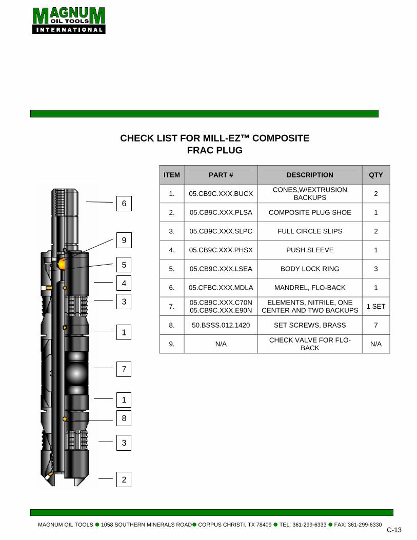
CHECK LIST FOR MILL-EZ™ COMPOSITE FRAC PLUG
ITEM PART # DESCRIPTION QTY
1. 05.CB9C.XXX.BUCX CONES,W/EXTRUSION BACKUPS 2
2. 05.CB9C.XXX.PLSA COMPOSITE PLUG SHOE 1
3. 05.CB9C.XXX.SLPC FULL CIRCLE SLIPS 2
4. 05.CB9C.XXX.PHSX PUSH SLEEVE 1
5. 05.CB9C.XXX.LSEA BODY LOCK RING 3
6. 05.CFBC.XXX.MDLA MANDREL, FLO-BACK 1
7. 05.CB9C.XXX.C70N 05.CB9C.XXX.E90N
ELEMENTS, NITRILE, ONE CENTER AND TWO BACKUPS 1 SET
8. 50.BSSS.012.1420 SET SCREWS, BRASS 7
9. N/A CHECK VALVE FOR FLO-BACK N/A
8
7
1
1
3
6
5
9
4
3
2


MAGNUM OIL TOOLS 10
DESCRIPTION: The Magnum Mill-EZ Cement Retainer, withconventional bridge abandonment. The slid“SSA” from the surfaceach zone and then remin one trip. Because oCement Retainer can This may be accomplisor with coiled tubing. FEATURES: • Wireline set
• Standard Setting To
• Mechanical setting
• Coil tubing set
• Positive seal after s
• Simple valve contro
• Minimum metal con
• Drill out with conven
• Fast drill out time
• Reduced rig time
OPERATION: Once the Magnum Milto the tubing string thenRetainer. The SSA ismandrel I.D. to isolate the stinger opens the sthe Composite Cemenpumping, hydraulic forallow for tubing movemor shorten the tubing an SPECIFICATIONS:
CASING
O.D. WEIGHT
CR
4.0” 9.50-13.00
4-1/2” 10.50-15.10
5.0” 11.50-20.00
5 ½” 15.50-23.00
“MAGNUM MILL-EZ™” COMPOSITE CEMENT RETAINER
58 SOUTHERN MINERALS ROAD CORPUS CHRISTI, TX 78409 TEL: 361-299-6333 FAX: 361-299-6330 C-15
Composite Cement Retainer is a slim design Composite a built in sliding sleeve check valve. This tool is set like a plug and is used for remedial cementing or zone e sleeve check valve is operated by a stinger seal assembly e. The operator can independently treat, squeeze, or test
ove the cement retainer in an under balanced environment f it’s low metallic content the Magnum Mill-EZ Composite be quickly and easily milled and circulated back to surface. hed with conventional milling or drilling with a rig and tubing
ols
tools
etting
l by surface manipulation
tent
tional milling operations
l-EZ Composite Cement Retainer is set, the SSA is attached the SSA is run to a depth just above the Composite Cement inserted into the plug bore. The stinger seals against the the tubing from the annulus. Slowly set down the tubing until lide collet, allowing communication to the well bore beneath t Retainer set 3,000-5,000lbs of weight on the plug. While
ce can vary. Before pumping use the proper calculations to ent, so as not to overload the Composite Cement Retainer d close the slide collet valve.
ement etainer O.D
Cement Retainer Length
LOW TEMP. &
Low PSI.
LOW TEMP. &
High PSI.
HIGH TEMP.
& High PSI.
Recommended Setting
Tool
3.25 16.0 250° / 8K 250° / 10K 350° / 10K Baker #10 or GO
3.60 16.0 250° / 8K 250° / 10K 350° / 10K Baker #10 or GO 3.92 16.0 250° / 8K 250° / 10K 350° / 10K Baker #10 or GO 4.40 16.0 250° / 8K 250° / 10K 350° / 10K Baker #20 or GO
MAGNUM OIL TOOLS 1058 SOUTHERN MINERALS ROAD CORPUS CHRISTI, TX 78409 TEL: 361-299-6333 FAX: 361-299-6330
C-16
Hydraulics Hydraulics of Cementing Operations: Various forces created by pressures applied to the casing and to the work string act on the Stinger Sub Assembly (“SSA”) and work string during cementing operations. These forces and their effects are governed by the size of the Stinger Sub Assembly, the size, weight per foot and length of the tubing or drill pipe, the mud weight, the annulus pressure and the work string pressure. Annulus Pressure When Tubing OD is greater than the Retainer Bore, the annulus pressure tends to lift the Stinger Sub Assembly upward trying to pull it out of the retainer. This force is equal to the annulus pressure (at the Cement Retainer) times the difference between the area of the tubing OD and the area of the Cement Retainer Bore. When the Tubing OD is less than the Retainer Bore, annulus pressure tends to push the Stinger Sub Assembly downward holding it in the retainer. This force is equal to the annulus pressure (at the Cement Retainer) times the difference between the area of the Cement Retainer Bore and the area of the tubing OD. Tubing Pressure When the Tubing ID is greater than the Retainer Bore, the tubing pressure tends to push the Stinger Sub Assembly downward holding it in the retainer. This force is equal to the tubing pressure (at the Cement Retainer) times the difference between the area of the tubing ID and the area of the Cement Retainer Bore. Also any pressure applied to the tubing string equal to the tubing pressure times the area of the tubing ID. This upward force reduces hook load but does not reduce the original slack off weight
on the Stinger Sub Assembly until the hook load is reduced to zero. When Tubing ID is less than the Retainer Bore, the tubing pressure tends to lift the Stinger Sub Assembly upward trying to pull it out of the retainer. This force is equal to the tubing pressure (at the Cement Retainer) times the difference between the area of the Cement Retainer Bore and the area of the tubing ID. Also, any pressure applied to the tubing exerts an upward force on the top of the tubing string equal to the tubing pressure times the area of the tubing ID. This upward force reduces hook load but does not reduce the original slack off weight on the Stinger Sub Assembly until the hook load is reduced to zero. The amount of weight that must be set on the Cement Retainer to keep the Stinger Sub Assembly in place and the Sliding Valve open depends on both the pressure in the annulus and in the work string. The amount of work string and annulus pressure that can be applied will therefore be limited for any size and length of work string. Use the “Area (in sq. in.) Acted Upon by Tubing and Annulus Pressures” table and the calculations in the next section to determine if the Stinger Sub will be lifted out of the retainer bore and the Cement Retainer Sliding Valve will be closed. Additional set down weight or changes in work string and annulus pressures will then be needed to keep the Stinger Sub Assembly in the retainer and hold the Sliding Valve open. How to Use Area Pressure Chart for the Mill-EZ Composite Cement Retainer The values given in the chart on the following page “Areas (in sq. in.) Acted Upon by Tubing and Annulus Pressures” are printed shaded and unshaded. These values are not only the number of square inches acted upon by the pressure change, but also the direction of the
MAGNUM OIL TOOLS 1058 SOUTHERN MINERALS ROAD CORPUS CHRISTI, TX 78409 TEL: 361-299-6333 FAX: 361-299-6330
C-17
resultant force. The areas shown unshaded will cause, with a pressure increase, and downward force tending to keep the Sliding Valve open. The areas shown shaded will result in an upward force, or a force tending to close the Sliding Valve. When the net force is upward additional setdown weight or altered annulus pressure must be used to keep the Valve open. Note: columns 1, 2, 4, 5, 6 and 7 must be multiplied by the change in pressure at the tool. Column 3 must be multiplied by the tubing gage pressure
1. Multiply the change in tubing pressure at the tool by Columns 1, 4, or 6, whichever is applicable.
2. Multiply the change in annulus pressure at the tool by Columns 2, 5 or 7, whichever is applicable. If the total of these two forces is tending to close the Sliding Valve additional set-down weight is required to overcome the new upward forces.
3. Multiply the tubing gage pressure by Column 3. Since Column 3 is always shaded, the resulting force tends to close the Sliding Valve by lifting the work string at the surface, This force is restricted to reducing the hook load until the hook load is reduced to zero. Any additional force will then act to lift the tubing string and Stinger Sub.
Add all three forces. If the result is a force tending to lift the Stinger Sub the Sliding Valve will be closed. Since hook load is the limiting factor, high pressures at relatively shallow depths might be prohibitive.
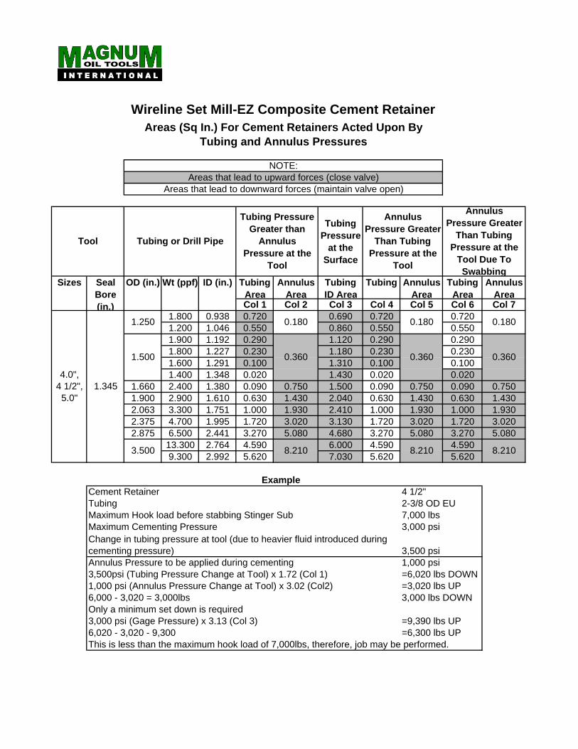
Wireline Set Mill-EZ Composite Cement RetainerAreas (Sq In.) For Cement Retainers Acted Upon By
Tubing and Annulus Pressures
NOTE:Areas that lead to upward forces (close valve)
Areas that lead to downward forces (maintain valve open)
Tool Tubing or Drill Pipe
Tubing Pressure Greater than
Annulus Pressure at the
Tool
Tubing Pressure
at the Surface
Annulus Pressure Greater
Than Tubing Pressure at the
Tool
Annulus Pressure Greater
Than Tubing Pressure at the
Tool Due To Swabbing
Sizes Seal Bore (in.)
OD (in.) Wt (ppf) ID (in.) Tubing Area
Annulus Area
Tubing ID Area
Tubing AnnulusArea
Tubing Area
Annulus Area
Col 1 Col 2 Col 3 Col 4 Col 5 Col 6 Col 7
4.0", 4 1/2", 5.0"
1.345
1.250 1.800 0.938 0.720 0.180 0.690 0.720 0.180 0.720 0.1801.200 1.046 0.550 0.860 0.550 0.550
1.500
1.900 1.192 0.290
0.360
1.120 0.290
0.360
0.290
0.3601.800 1.227 0.230 1.180 0.230 0.2301.600 1.291 0.100 1.310 0.100 0.1001.400 1.348 0.020 1.430 0.020 0.020
1.660 2.400 1.380 0.090 0.750 1.500 0.090 0.750 0.090 0.7501.900 2.900 1.610 0.630 1.430 2.040 0.630 1.430 0.630 1.4302.063 3.300 1.751 1.000 1.930 2.410 1.000 1.930 1.000 1.9302.375 4.700 1.995 1.720 3.020 3.130 1.720 3.020 1.720 3.0202.875 6.500 2.441 3.270 5.080 4.680 3.270 5.080 3.270 5.080
3.500 13.300 2.764 4.590 8.210 6.000 4.590 8.210 4.590 8.2109.300 2.992 5.620 7.030 5.620 5.620
ExampleCement Retainer 4 1/2"Tubing 2-3/8 OD EUMaximum Hook load before stabbing Stinger Sub 7,000 lbsMaximum Cementing Pressure 3,000 psiChange in tubing pressure at tool (due to heavier fluid introduced during cementing pressure) 3,500 psiAnnulus Pressure to be applied during cementing 1,000 psi3,500psi (Tubing Pressure Change at Tool) x 1.72 (Col 1) =6,020 lbs DOWN1,000 psi (Annulus Pressure Change at Tool) x 3.02 (Col2) =3,020 lbs UP6,000 - 3,020 = 3,000lbs 3,000 lbs DOWNOnly a minimum set down is required3,000 psi (Gage Pressure) x 3.13 (Col 3) =9,390 lbs UP6,020 - 3,020 - 9,300 =6,300 lbs UPThis is less than the maximum hook load of 7,000lbs, therefore, job may be performed.
D TUBING CONVEYED
PERFORATING SYSTEMS

FIRING HEADS
MA
MAGNUM HYDRAULIC ABSOLUTE FIRING HEAD ASSEMBLY
SPE
TOP BOTTOOMAXMAXLENGWEIGPARRED
* OTH
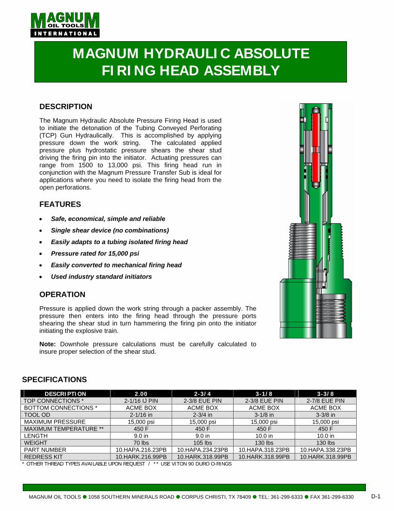
DESCRIPTION The Magnum Hydraulic Absolute Pressure Firing Head is used to initiate the detonation of the Tubing Conveyed Perforating (TCP) Gun Hydraulically. This is accomplished by applying pressure down the work string. The calculated applied pressure plus hydrostatic pressure shears the shear stud driving the firing pin into the initiator. Actuating pressures can range from 1500 to 13,000 psi. This firing head run in conjunction with the Magnum Pressure Transfer Sub is ideal for applications where you need to isolate the firing head from the open perforations.
GNUM OIL TOOLS 1058 SOUTHERN MINERALS ROAD CORPUS CHRISTI, TX 78409 TEL: 361-299-6333 FAX 361-299-6330 D-1
FEATURES • Safe, economical, simple and reliable
• Single shear device (no combinations)
• Easily adapts to a tubing isolated firing head
• Pressure rated for 15,000 psi
• Easily converted to mechanical firing head
• Used industry standard initiators OPERATION Pressure is applied down the work string through a packer assembly. The pressure then enters into the firing head through the pressure ports shearing the shear stud in turn hammering the firing pin onto the initiator initiating the explosive train. Note: Downhole pressure calculations must be carefully calculated to insure proper selection of the shear stud.
CIFICATIONS
DESCRIPTION 2.00 2-3/4 3-1/8 3-3/8 CONNECTIONS * 2-1/16 IJ PIN 2-3/8 EUE PIN 2-3/8 EUE PIN 2-7/8 EUE PIN TOM CONNECTIONS * ACME BOX ACME BOX ACME BOX ACME BOX L OD 2-1/16 in 2-3/4 in 3-1/8 in 3-3/8 in IMUM PRESSURE 15,000 psi 15,000 psi 15,000 psi 15,000 psi IMUM TEMPERATURE ** 450 F 450 F 450 F 450 F
TH 9.0 in 9.0 in 10.0 in 10.0 in HT 70 lbs 105 lbs 130 lbs 130 lbs
T NUMBER 10.HAPA.216.23PB 10.HAPA.234.23PB 10.HAPA.318.23PB 10.HAPA.338.23PB RESS KIT 10.HARK.216.99PB 10.HARK.318.99PB 10.HARK.318.99PB 10.HARK.318.99PB ER THREAD TYPES AVAILABLE UPON REQUEST / ** USE VITON 90 DURO O-RINGS
MAGNUM OIL TOOLS 1058 SOUTHERN MINERALS ROAD CORPUS CHRISTI, TX 78409 TEL: 361-299-6333 FAX 361-299-6330 D-2
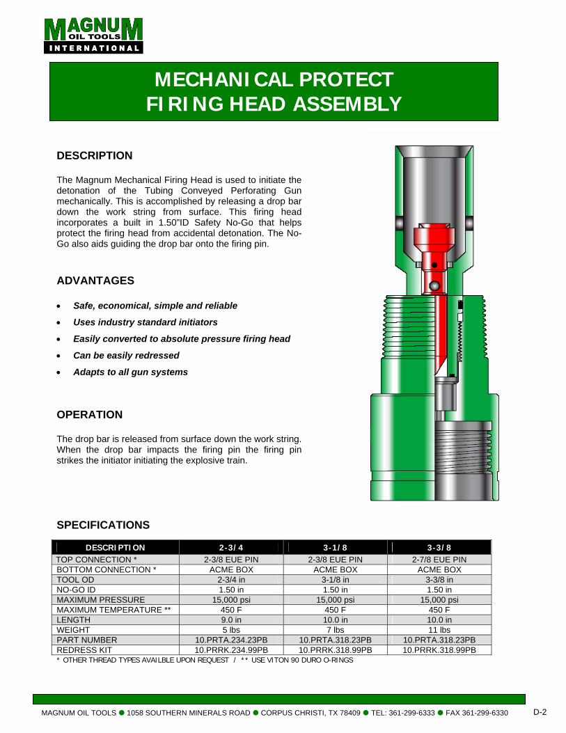
MECHANICAL PROTECT FIRING HEAD ASSEMBLY
DESCRIPTION The Magnum Mechanical Firing Head is used to initiate the detonation of the Tubing Conveyed Perforating Gun mechanically. This is accomplished by releasing a drop bar down the work string from surface. This firing head incorporates a built in 1.50”ID Safety No-Go that helps protect the firing head from accidental detonation. The No-Go also aids guiding the drop bar onto the firing pin.
• Can be easily redressed
• Adapts to all gun systems
OPERATION The drop bar is released from surface down the work string. When the drop bar impacts the firing pin the firing pin strikes the initiator initiating the explosive train.
ADVANTAGES • Safe, economical, simple and reliable
• Uses industry standard initiators
• Easily converted to absolute pressure firing head
SPECIFICATIONS
DESCRIPTION 2-3/4 3-1/8 3-3/8 TOP CONNECTION * 2-3/8 EUE PIN 2-3/8 EUE PIN 2-7/8 EUE PIN BOTTOM CONNECTION * ACME BOX ACME BOX ACME BOX TOOL OD 2-3/4 in 3-1/8 in 3-3/8 in NO-GO ID 1.50 in 1.50 in 1.50 in MAXIMUM PRESSURE 15,000 psi 15,000 psi 15,000 psi MAXIMUM TEMPERATURE ** 450 F 450 F 450 F LENGTH 9.0 in 10.0 in 10.0 in WEIGHT 5 lbs 7 lbs 11 lbs PART NUMBER 10.PRTA.234.23PB 10.PRTA.318.23PB 10.PRTA.318.23PB REDRESS KIT 10.PRRK.234.99PB 10.PRRK.318.99PB 10.PRRK.318.99PB * OTHER THREAD TYPES AVAILBLE UPON REQUEST / ** USE VITON 90 DURO O-RINGS
MAGNUM OIL T
DESCR The Magnto initiate(TCP) guimmediateby a presscord. Aftestring to abuilt in 1.from accidbar onto t
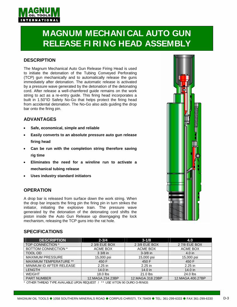
MAGNUM MECHANICAL AUTO GUN RELEASE FIRING HEAD ASSEMBLY
IPTION
um Mechanical Auto Gun Release Firing Head is used the detonation of the Tubing Conveyed Perforating n mechanically and to automatically release the guns ly after detonation. The automatic release is activated ure wave generated by the detonation of the detonating r release a well-chamfered guide remains on the work ct as a re-entry guide. This firing head incorporates a
50”ID Safety No-Go that helps protect the firing head ental detonation. The No-Go also aids guiding the drop
he firing pin.
ADVANTAGES • Safe, economical, simple and reliable
• Easily converts to an absolute pressure auto gun release firing head
• Can be run with the completion string therefore saving rig time
• Eliminates the need for a wireline run to activate a mechanical tubing release
• Uses industry standard initiators OPERATION A drop bar is released from surface down the work string. When the drop bar impacts the firing pin the firing pin in turn strikes the initiator, initiating the explosive train. The pressure wave generated by the detonation of the detonating cord shifts the piston inside the Auto Gun Release up disengaging the lock mechanism, releasing the TCP guns into the rat hole.
SPECIFICATIONS
DESCRIPTION 2-3/4 3-1/8 4.0 TOP CONNECTION * 2 3/8 EUE BOX 2 3/8 EUE BOX 2 7/8 EUE BOX BOTTOM CONNECTION * ACME BOX ACME BOX ACME BOX TOOL OD 3 3/8 in 3-3/8 in 4.0 in MAXIMUM PRESSURE 15,000 psi 15,000 psi 15,000 psi MAXIMUM TEMPERATURE ** 450 F 450 F 450 F MINIMUM ID AFTER RELEASE 2.25 in 2.25 in 2.25 in LENGTH 14.0 in 14.0 in 14.0 in WEIGHT 18.0 lbs 21.0 lbs 24.0 lbs PART NUMBER 12.MAGA.234.23BP 12.MAGA.318.23BP 12.MAGA.400.27BP
* OTHER THREAD TYPE AVAILABLE UPON REQUEST / ** USE VITON 90 DURO O-RINGS
OOLS 1058 SOUTHERN MINERALS ROAD CORPUS CHRISTI, TX 78409 TEL: 361-299-6333 FAX 361-299-6330 D-3
MAGNUM OIL TOOLS 1058 SOUTHERN MINERALS ROAD CORPUS CHRISTI, TX 78409 TEL: 361-299-6333 FAX 361-299-6330 D-4
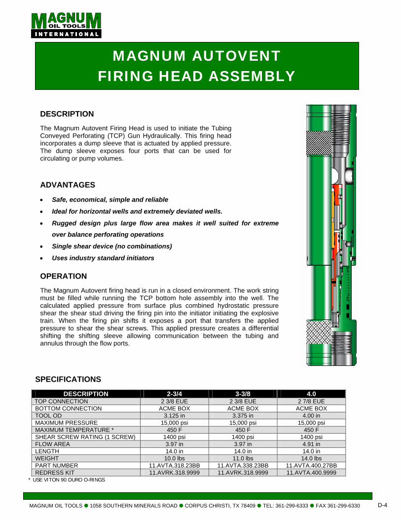
MAGNUM AUTOVENT FIRING HEAD ASSEMBLY
DESCRIPTION The Magnum Autovent Firing Head is used to initiate the Tubing Conveyed Perforating (TCP) Gun Hydraulically. This firing head incorporates a dump sleeve that is actuated by applied pressure. The dump sleeve exposes four ports that can be used for circulating or pump volumes.
ADVANTAGES • Safe, economical, simple and reliable
• Ideal for horizontal wells and extremely deviated wells.
• Rugged design plus large flow area makes it well suited for extreme over balance perforating operations
• Single shear device (no combinations)
• Uses industry standard initiators OPERATION The Magnum Autovent firing head is run in a closed environment. The work string must be filled while running the TCP bottom hole assembly into the well. The calculated applied pressure from surface plus combined hydrostatic pressure shear the shear stud driving the firing pin into the initiator initiating the explosive train. When the firing pin shifts it exposes a port that transfers the applied pressure to shear the shear screws. This applied pressure creates a differential shifting the shifting sleeve allowing communication between the tubing and annulus through the flow ports.
SPECIFICATIONS
DESCRIPTION 2-3/4 3-3/8 4.0 TOP CONNECTION 2 3/8 EUE 2 3/8 EUE 2 7/8 EUE BOTTOM CONNECTION ACME BOX ACME BOX ACME BOX TOOL OD 3.125 in 3.375 in 4.00 in MAXIMUM PRESSURE 15,000 psi 15,000 psi 15,000 psi MAXIMUM TEMPERATURE * 450 F 450 F 450 F SHEAR SCREW RATING (1 SCREW) 1400 psi 1400 psi 1400 psi FLOW AREA 3.97 in 3.97 in 4.91 in LENGTH 14.0 in 14.0 in 14.0 in WEIGHT 10.0 lbs 11.0 lbs 14.0 lbs PART NUMBER 11.AVTA.318.23BB 11.AVTA.338.23BB 11.AVTA.400.27BB REDRESS KIT 11.AVRK.318.9999 11.AVRK.318.9999 11.AVTA.400.9999
* USE VITON 90 DURO O-RINGS
MAGNUM OIL TOOLS 1058 SOUTHERN MINERALS ROAD CORPUS CHRISTI, TX 78409 TEL: 361-299-6333 FAX 361-299-6330 D-5
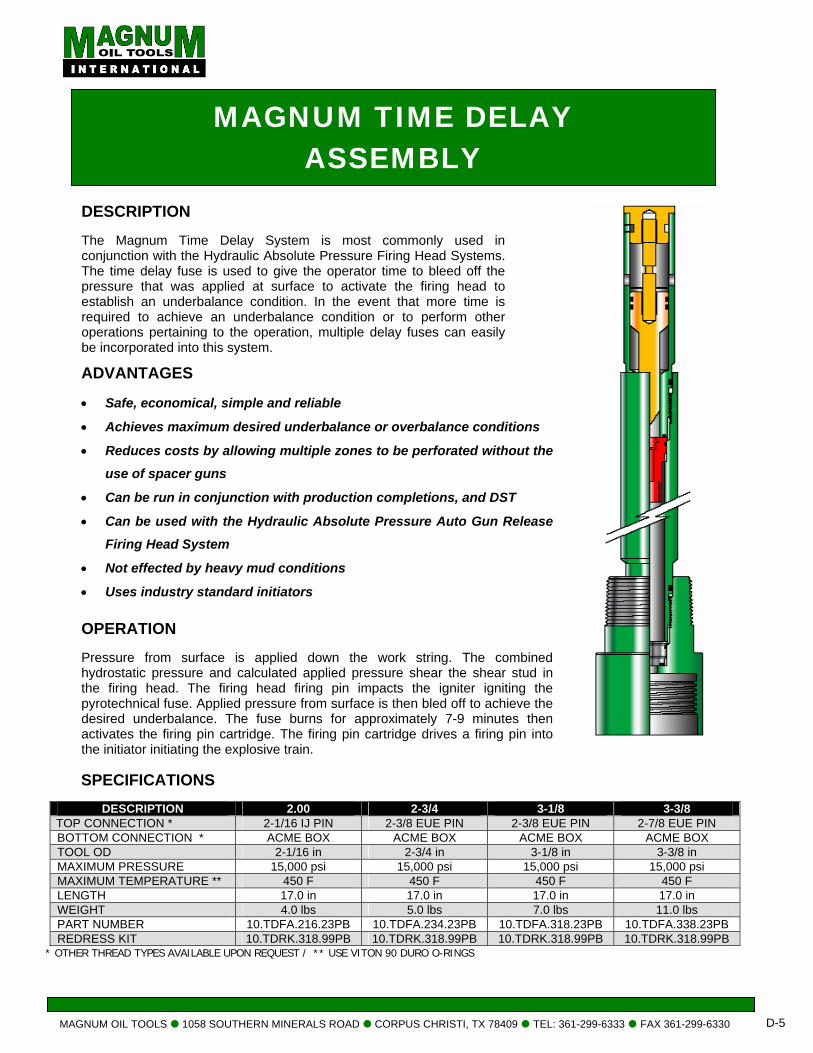
MAGNUM TIME DELAY ASSEMBLY
DESCRIPTION The Magnum Time Delay System is most commonly used in conjunction with the Hydraulic Absolute Pressure Firing Head Systems. The time delay fuse is used to give the operator time to bleed off the pressure that was applied at surface to activate the firing head to establish an underbalance condition. In the event that more time is required to achieve an underbalance condition or to perform other operations pertaining to the operation, multiple delay fuses can easily be incorporated into this system.
ADVANTAGES • Safe, economical, simple and reliable
• Achieves maximum desired underbalance or overbalance conditions
• Reduces costs by allowing multiple zones to be perforated without the use of spacer guns
• Can be run in conjunction with production completions, and DST
• Can be used with the Hydraulic Absolute Pressure Auto Gun Release Firing Head System
• Not effected by heavy mud conditions
• Uses industry standard initiators OPERATION Pressure from surface is applied down the work string. The combined hydrostatic pressure and calculated applied pressure shear the shear stud in the firing head. The firing head firing pin impacts the igniter igniting the pyrotechnical fuse. Applied pressure from surface is then bled off to achieve the desired underbalance. The fuse burns for approximately 7-9 minutes then activates the firing pin cartridge. The firing pin cartridge drives a firing pin into the initiator initiating the explosive train.
SPECIFICATIONS
DESCRIPTION 2.00 2-3/4 3-1/8 3-3/8 TOP CONNECTION * 2-1/16 IJ PIN 2-3/8 EUE PIN 2-3/8 EUE PIN 2-7/8 EUE PIN BOTTOM CONNECTION * ACME BOX ACME BOX ACME BOX ACME BOX TOOL OD 2-1/16 in 2-3/4 in 3-1/8 in 3-3/8 in MAXIMUM PRESSURE 15,000 psi 15,000 psi 15,000 psi 15,000 psi MAXIMUM TEMPERATURE ** 450 F 450 F 450 F 450 F LENGTH 17.0 in 17.0 in 17.0 in 17.0 in WEIGHT 4.0 lbs 5.0 lbs 7.0 lbs 11.0 lbs PART NUMBER 10.TDFA.216.23PB 10.TDFA.234.23PB 10.TDFA.318.23PB 10.TDFA.338.23PB REDRESS KIT 10.TDRK.318.99PB 10.TDRK.318.99PB 10.TDRK.318.99PB 10.TDRK.318.99PB
* OTHER THREAD TYPES AVAILABLE UPON REQUEST / ** USE VITON 90 DURO O-RINGS
MAGNUM OIL TOOLS 1058 SOUTHERN MINERALS ROAD CORPUS CHRISTI, TX 78409 TEL: 361-299-6333 FAX 361-299-6330 D-6
HYDRO-MECHANICAL FIRING HEAD ASSEMBLY
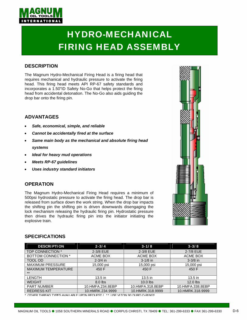
DESCRIPTION The Magnum Hydro-Mechanical Firing Head is a firing head that requires mechanical and hydraulic pressure to activate the firing head. This firing head meets API RP-67 safety standards and incorporates a 1.50”ID Safety No-Go that helps protect the firing head from accidental detonation. The No-Go also aids guiding the drop bar onto the firing pin.
ADVANTAGES • Safe, economical, simple, and reliable
• Cannot be accidentally fired at the surface
• Same main body as the mechanical and absolute firing head systems
• Ideal for heavy mud operations
• Meets RP-67 guidelines
• Uses industry standard initiators OPERATION The Magnum Hydro-Mechanical Firing Head requires a minimum of 500psi hydrostatic pressure to activate the firing head. The drop bar is released from surface down the work string. When the drop bar impacts the shifting pin the shifting pin is driven downwards disengaging the lock mechanism releasing the hydraulic firing pin. Hydrostatic pressure then drives the hydraulic firing pin into the initiator initiating the explosive train.
SPECIFICATIONS
DESCRIPTION 2-3/4 3-1/8 3-3/8 TOP CONNECTION * 2-3/8 EUE 2-3/8 EUE 2-7/8 EUE BOTTOM CONNECTION * ACME BOX ACME BOX ACME BOX TOOL OD 2-3/4 in 3-1/8 in 3-3/8 in MAXIMUM PRESSURE 15,000 psi 15,000 psi 15,000 psi MAXIMUM TEMPERATURE **
450 F 450 F 450 F
LENGTH 13.5 in 13.5 in 13.5 in WEIGHT 8.0 lbs 10.0 lbs 12.0 lbs PART NUMBER 10.HMFA.234.8EBP 10.HMFA.318.8EBP 10.HMFA.338.8EBP REDRESS KIT 10.HMRK.234.9999 10.HMRK.318.9999 10.HMRK.318.9999
* OTHER THREAD TYPES AVAILABLE UPON REQUEST / ** USE VITON 90 DURO O-RINGS
MAGNUM OIL TOOLS 1058 SOUTHERN MINERALS ROAD CORPUS CHRISTI, TX 78409 TEL: 361-299-6333 FAX 361-299-6330 D-7
1-11/16 DIFFERENTIAL PRESSURECOIL TUBING FIRING HEAD ASSEMBLY
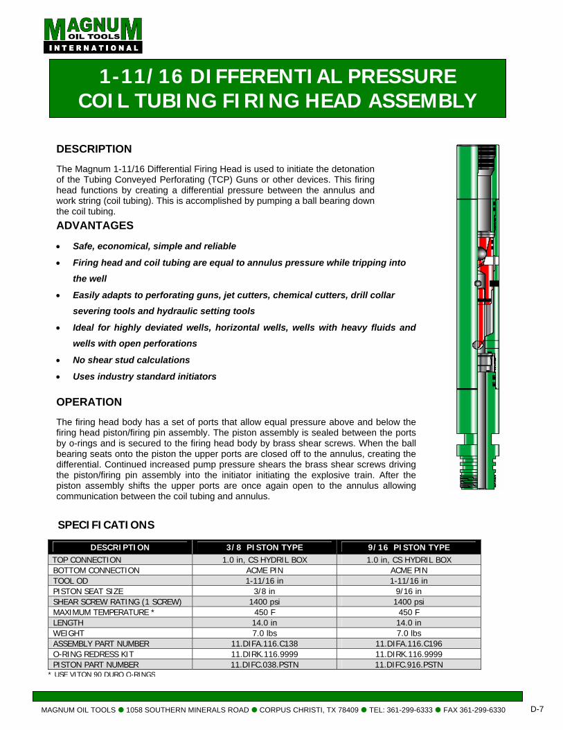
DESCRIPTION The Magnum 1-11/16 Differential Firing Head is used to initiate the detonation of the Tubing Conveyed Perforating (TCP) Guns or other devices. This firing head functions by creating a differential pressure between the annulus and work string (coil tubing). This is accomplished by pumping a ball bearing down the coil tubing.
SPECIFICATIONS
DESCRIPTION 3/8 PISTON TYPE 9/16 PISTON TYPE TOP CONNECTION 1.0 in, CS HYDRIL BOX 1.0 in, CS HYDRIL BOX BOTTOM CONNECTION ACME PIN ACME PIN TOOL OD 1-11/16 in 1-11/16 in PISTON SEAT SIZE 3/8 in 9/16 in SHEAR SCREW RATING (1 SCREW) 1400 psi 1400 psi MAXIMUM TEMPERATURE * 450 F 450 F LENGTH 14.0 in 14.0 in WEIGHT 7.0 lbs 7.0 lbs ASSEMBLY PART NUMBER 11.DIFA.116.C138 11.DIFA.116.C196 O-RING REDRESS KIT 11.DIRK.116.9999 11.DIRK.116.9999 PISTON PART NUMBER 11.DIFC.038.PSTN 11.DIFC.916.PSTN
* USE VITON 90 DURO O-RINGS
ADVANTAGES • Safe, economical, simple and reliable
• Firing head and coil tubing are equal to annulus pressure while tripping into
the well
• Easily adapts to perforating guns, jet cutters, chemical cutters, drill collar
severing tools and hydraulic setting tools
• Ideal for highly deviated wells, horizontal wells, wells with heavy fluids and
wells with open perforations
• No shear stud calculations
• Uses industry standard initiators OPERATION The firing head body has a set of ports that allow equal pressure above and below the firing head piston/firing pin assembly. The piston assembly is sealed between the ports by o-rings and is secured to the firing head body by brass shear screws. When the ball bearing seats onto the piston the upper ports are closed off to the annulus, creating the differential. Continued increased pump pressure shears the brass shear screws driving the piston/firing pin assembly into the initiator initiating the explosive train. After the piston assembly shifts the upper ports are once again open to the annulus allowing communication between the coil tubing and annulus.
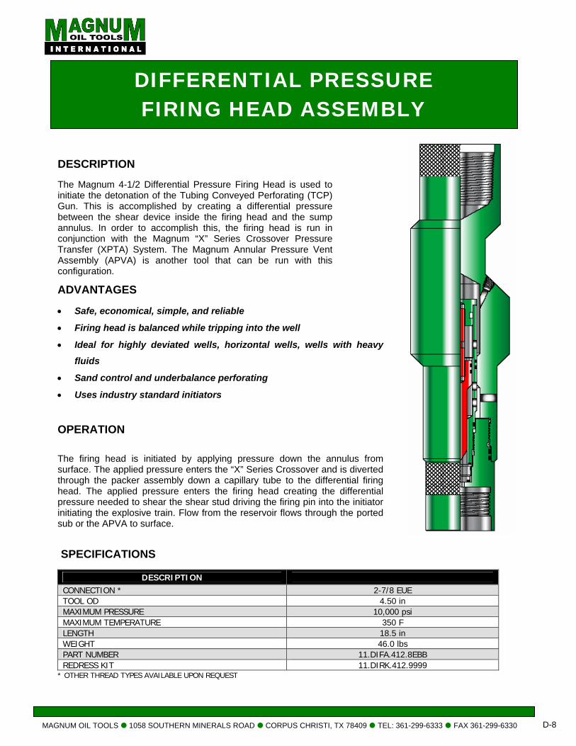
MAGNUM OIL TOOLS 1058 SOUTHERN MINERALS ROAD CORPUS CHRISTI, TX 78409 TEL: 361-299-6333 FAX 361-299-6330 D-8
DIFFERENTIAL PRESSURE FIRING HEAD ASSEMBLY
DESCRIPTION The Magnum 4-1/2 Differential Pressure Firing Head is used to initiate the detonation of the Tubing Conveyed Perforating (TCP) Gun. This is accomplished by creating a differential pressure between the shear device inside the firing head and the sump annulus. In order to accomplish this, the firing head is run in conjunction with the Magnum “X” Series Crossover Pressure Transfer (XPTA) System. The Magnum Annular Pressure Vent Assembly (APVA) is another tool that can be run with this configuration. ADVANTAGES • Safe, economical, simple, and reliable
• Firing head is balanced while tripping into the well
• Ideal for highly deviated wells, horizontal wells, wells with heavy fluids
• Sand control and underbalance perforating
• Uses industry standard initiators OPERATION The firing head is initiated by applying pressure down the annulus from surface. The applied pressure enters the “X” Series Crossover and is diverted through the packer assembly down a capillary tube to the differential firing head. The applied pressure enters the firing head creating the differential pressure needed to shear the shear stud driving the firing pin into the initiator initiating the explosive train. Flow from the reservoir flows through the ported sub or the APVA to surface.
SPECIFICATIONS
DESCRIPTION CONNECTION * 2-7/8 EUE TOOL OD 4.50 in MAXIMUM PRESSURE 10,000 psi MAXIMUM TEMPERATURE 350 F LENGTH 18.5 in WEIGHT 46.0 lbs PART NUMBER 11.DIFA.412.8EBB REDRESS KIT 11.DIRK.412.9999
* OTHER THREAD TYPES AVAILABLE UPON REQUEST

VENT SUBS
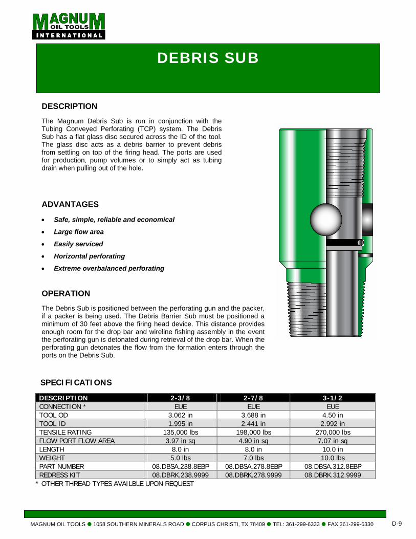
MAGNUM OIL TOOLS 1058 SOUTHERN MINERALS ROAD CORPUS CHRISTI, TX 78409 TEL: 361-299-6333 FAX 361-299-6330 D-9
DESCRIPTION The Magnum Debris Sub is run in conjunction with the Tubing Conveyed Perforating (TCP) system. The Debris Sub has a flat glass disc secured across the ID of the tool. The glass disc acts as a debris barrier to prevent debris from settling on top of the firing head. The ports are used for production, pump volumes or to simply act as tubing drain when pulling out of the hole.
ADVANTAGES • Safe, simple, reliable and economical
• Large flow area
• Easily serviced
• Horizontal perforating
• Extreme overbalanced perforating OPERATION The Debris Sub is positioned between the perforating gun and the packer, if a packer is being used. The Debris Barrier Sub must be positioned a minimum of 30 feet above the firing head device. This distance provides enough room for the drop bar and wireline fishing assembly in the event the perforating gun is detonated during retrieval of the drop bar. When the perforating gun detonates the flow from the formation enters through the ports on the Debris Sub.
SPECIFICATIONS DESCRIPTION 2-3/8 2-7/8 3-1/2 CONNECTION * EUE EUE EUE TOOL OD 3.062 in 3.688 in 4.50 in TOOL ID 1.995 in 2.441 in 2.992 in TENSILE RATING 135,000 lbs 198,000 lbs 270,000 lbs FLOW PORT FLOW AREA 3.97 in sq 4.90 in sq 7.07 in sq LENGTH 8.0 in 8.0 in 10.0 in WEIGHT 5.0 lbs 7.0 lbs 10.0 lbs PART NUMBER 08.DBSA.238.8EBP 08.DBSA.278.8EBP 08.DBSA.312.8EBP REDRESS KIT 08.DBRK.238.9999 08.DBRK.278.9999 08.DBRK.312.9999
* OTHER THREAD TYPES AVAILBLE UPON REQUEST
DEBRIS SUB
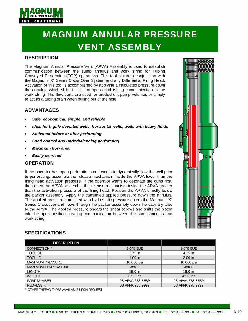
MAGNUM OIL TOOLS 1058 SOUTHERN MINERALS ROAD CORPUS CHRISTI, TX 78409 TEL: 361-299-6333 FAX 361-299-6330 D-10
MAGNUM ANNULAR PRESSURE VENT ASSEMBLY
DESCRIPTION The Magnum Annular Pressure Vent (APVA) Assembly is used to establish communication between the sump annulus and work string for Tubing Conveyed Perforating (TCP) operations. This tool is run in conjunction with the Magnum “X” Series Cross Over System and any Differential Firing Head. Activation of this tool is accomplished by applying a calculated pressure down the annulus, which shifts the piston open establishing communication to the work string. The flow ports are used for production, pump volumes or simply to act as a tubing drain when pulling out of the hole.
ADVANTAGES • Safe, economical, simple, and reliable
• Ideal for highly deviated wells, horizontal wells, wells with heavy fluids
• Activated before or after perforating
• Sand control and underbalancing perforating
• Maximum flow area
• Easily serviced
OPERATION If the operator has open perforations and wants to dynamically flow the well prior to perforating, assemble the release mechanism inside the APVA lower than the firing head activation pressure. If the operator wants to detonate the guns first, then open the APVA; assemble the release mechanism inside the APVA greater than the activation pressure of the firing head. Position the APVA directly below the packer assembly. Apply the calculated applied pressure down the annulus. The applied pressure combined with hydrostatic pressure enters the Magnum “X” Series Crossover and flows through the packer assembly down the capillary tube to the APVA. The applied pressure shears the shear screws and shifts the piston into the open position creating communication between the sump annulus and work string.
SPECIFICATIONS
DESCRIPTION CONNECTION * 2-3/8 EUE 2-7/8 EUE TOOL OD 3.75 in 4.25 in TOOL ID 1.00 in 2.00 in MAXIMUM PRESSURE 10,000 psi 10,000 psi MAXIMUM TEMPERATURE 350 F 350 F LENGTH 16.0 in 16.0 in WEIGHT 37.0 lbs 42.0 lbs PART NUMBER 08.APVA.238.8EBP 08.APVA.278.8EBP REDRESS KIT 08.APRK.238.9999 08.APRK.278.9999
* OTHER THREAD TYPES AVAILABLE UPON REQUEST
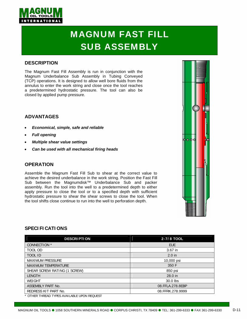
MAGNUM OIL TOOLS 1058 SOUTHERN MINERALS ROAD CORPUS CHRISTI, TX 78409 TEL: 361-299-6333 FAX 361-299-6330 D-11
MAGNUM FAST FILL SUB ASSEMBLY
DESCRIPTION The Magnum Fast Fill Assembly is run in conjunction with the Magnum Underbalance Sub Assembly in Tubing Conveyed (TCP) operations. It is designed to allow well bore fluids from the annulus to enter the work string and close once the tool reaches a predetermined hydrostatic pressure. The tool can also be closed by applied pump pressure.
ADVANTAGES
• Economical, simple, safe and reliable
• Full opening
• Multiple shear value settings
• Can be used with all mechanical firing heads OPERATION Assemble the Magnum Fast Fill Sub to shear at the correct value to achieve the desired underbalance in the work string. Position the Fast Fill Sub between the Magnumdisk™ Underbalance Sub and packer assembly. Run the tool into the well to a predetermined depth to either apply pressure to close the tool or to a specified depth with sufficient hydrostatic pressure to shear the shear screws to close the tool. When the tool shifts close continue to run into the well to perforation depth.
SPECIFICATIONS
DESCRIPTION 2-7/8 TOOL
CONNECTION * EUE TOOL OD 3.67 in TOOL ID 2.0 in MAXIMUM PRESSURE 10,000 psi MAXIMUM TEMPERATURE 350 F SHEAR SCREW RATING (1 SCREW) 850 psi LENGTH 28.0 in WEIGHT 30.0 lbs ASSEMBLY PART No. 08.FFLA.278.8EBP REDRESS KIT PART No. 08.FFRK.278.9999
* OTHER THREAD TYPES AVAILABLE UPON REQUEST
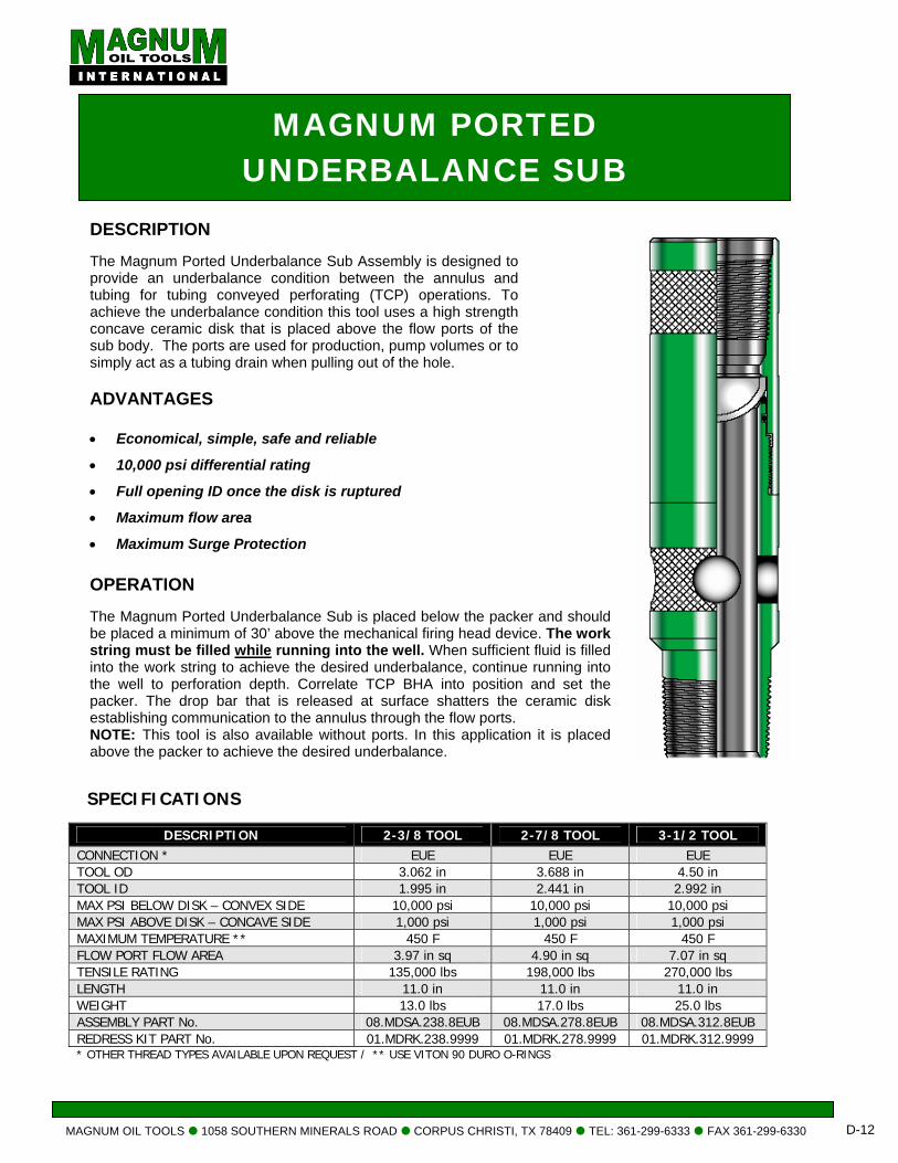
MAGNUM OIL TOOLS 1058 SOUTHERN MINERALS ROAD CORPUS CHRISTI, TX 78409 TEL: 361-299-6333 FAX 361-299-6330 D-12
MAGNUM PORTED UNDERBALANCE SUB
ADVANTAGES
• Economical, simple, safe and reliable
• 10,000 psi differential rating
• Full opening ID once the disk is ruptured
• Maximum flow area
• Maximum Surge Protection OPERATION The Magnum Ported Underbalance Sub is placed below the packer and should be placed a minimum of 30’ above the mechanical firing head device. The work string must be filled while running into the well. When sufficient fluid is filled into the work string to achieve the desired underbalance, continue running into the well to perforation depth. Correlate TCP BHA into position and set the packer. The drop bar that is released at surface shatters the ceramic disk establishing communication to the annulus through the flow ports. NOTE: This tool is also available without ports. In this application it is placed above the packer to achieve the desired underbalance.
DESCRIPTION The Magnum Ported Underbalance Sub Assembly is designed to provide an underbalance condition between the annulus and tubing for tubing conveyed perforating (TCP) operations. To achieve the underbalance condition this tool uses a high strength concave ceramic disk that is placed above the flow ports of the sub body. The ports are used for production, pump volumes or to simply act as a tubing drain when pulling out of the hole.
SPECIFICATIONS
DESCRIPTION 2-3/8 TOOL 2-7/8 TOOL 3-1/2 TOOL CONNECTION * EUE EUE EUE TOOL OD 3.062 in 3.688 in 4.50 in TOOL ID 1.995 in 2.441 in 2.992 in MAX PSI BELOW DISK – CONVEX SIDE 10,000 psi 10,000 psi 10,000 psi MAX PSI ABOVE DISK – CONCAVE SIDE 1,000 psi 1,000 psi 1,000 psi MAXIMUM TEMPERATURE ** 450 F 450 F 450 F FLOW PORT FLOW AREA 3.97 in sq 4.90 in sq 7.07 in sq TENSILE RATING 135,000 lbs 198,000 lbs 270,000 lbs LENGTH 11.0 in 11.0 in 11.0 in WEIGHT 13.0 lbs 17.0 lbs 25.0 lbs ASSEMBLY PART No. 08.MDSA.238.8EUB 08.MDSA.278.8EUB 08.MDSA.312.8EUB REDRESS KIT PART No. 01.MDRK.238.9999 01.MDRK.278.9999 01.MDRK.312.9999 * OTHER THREAD TYPES AVAILABLE UPON REQUEST / ** USE VITON 90 DURO O-RINGS
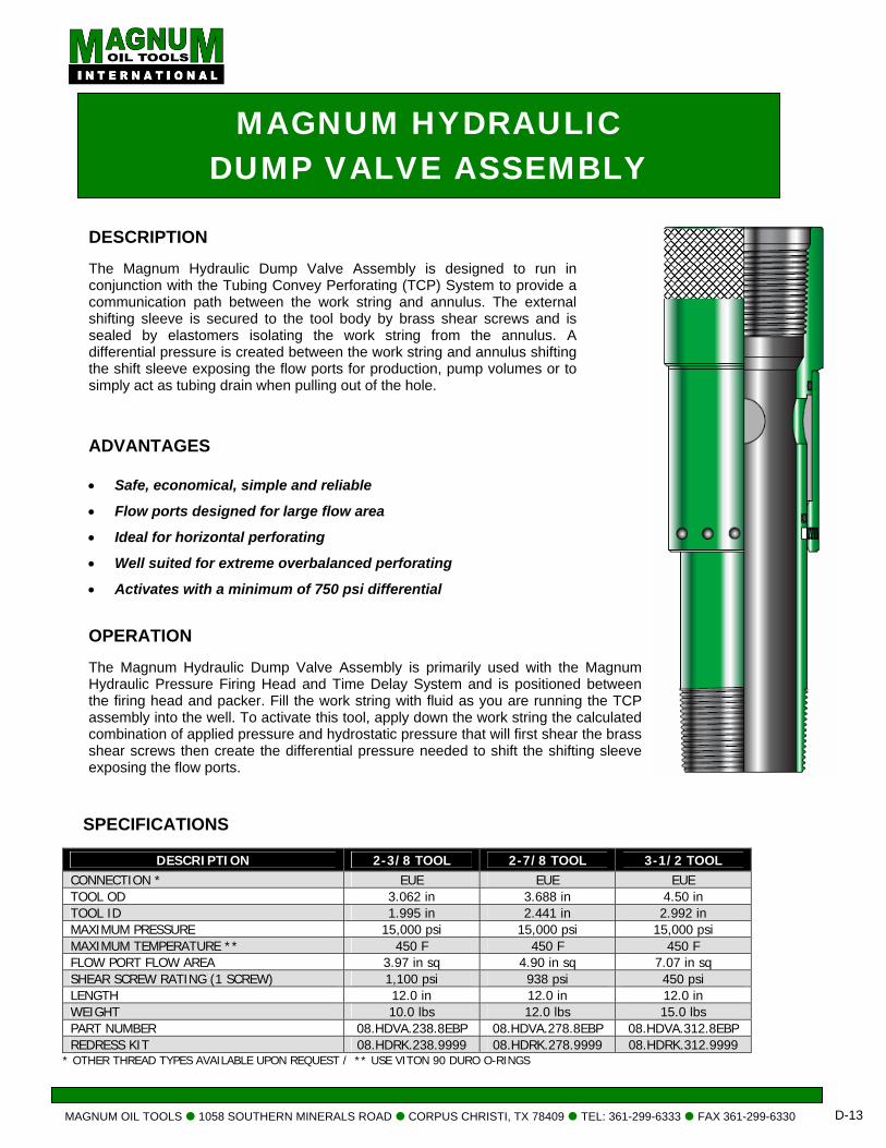
MAGNUM OIL TOOLS 1058 SOUTHERN MINERALS ROAD CORPUS CHRISTI, TX 78409 TEL: 361-299-6333 FAX 361-299-6330 D-13
MAGNUM HYDRAULIC DUMP VALVE ASSEMBLY
DESCRIPTION The Magnum Hydraulic Dump Valve Assembly is designed to run in conjunction with the Tubing Convey Perforating (TCP) System to provide a communication path between the work string and annulus. The external shifting sleeve is secured to the tool body by brass shear screws and is sealed by elastomers isolating the work string from the annulus. A differential pressure is created between the work string and annulus shifting the shift sleeve exposing the flow ports for production, pump volumes or to simply act as tubing drain when pulling out of the hole.
ADVANTAGES
• Safe, economical, simple and reliable
• Flow ports designed for large flow area
• Ideal for horizontal perforating
• Well suited for extreme overbalanced perforating
• Activates with a minimum of 750 psi differential
OPERATION The Magnum Hydraulic Dump Valve Assembly is primarily used with the Magnum Hydraulic Pressure Firing Head and Time Delay System and is positioned between the firing head and packer. Fill the work string with fluid as you are running the TCP assembly into the well. To activate this tool, apply down the work string the calculated combination of applied pressure and hydrostatic pressure that will first shear the brass shear screws then create the differential pressure needed to shift the shifting sleeve exposing the flow ports.
SPECIFICATIONS
DESCRIPTION 2-3/8 TOOL 2-7/8 TOOL 3-1/2 TOOL CONNECTION * EUE EUE EUE TOOL OD 3.062 in 3.688 in 4.50 in TOOL ID 1.995 in 2.441 in 2.992 in MAXIMUM PRESSURE 15,000 psi 15,000 psi 15,000 psi MAXIMUM TEMPERATURE ** 450 F 450 F 450 F FLOW PORT FLOW AREA 3.97 in sq 4.90 in sq 7.07 in sq SHEAR SCREW RATING (1 SCREW) 1,100 psi 938 psi 450 psi LENGTH 12.0 in 12.0 in 12.0 in WEIGHT 10.0 lbs 12.0 lbs 15.0 lbs PART NUMBER 08.HDVA.238.8EBP 08.HDVA.278.8EBP 08.HDVA.312.8EBP REDRESS KIT 08.HDRK.238.9999 08.HDRK.278.9999 08.HDRK.312.9999
* OTHER THREAD TYPES AVAILABLE UPON REQUEST / ** USE VITON 90 DURO O-RINGS
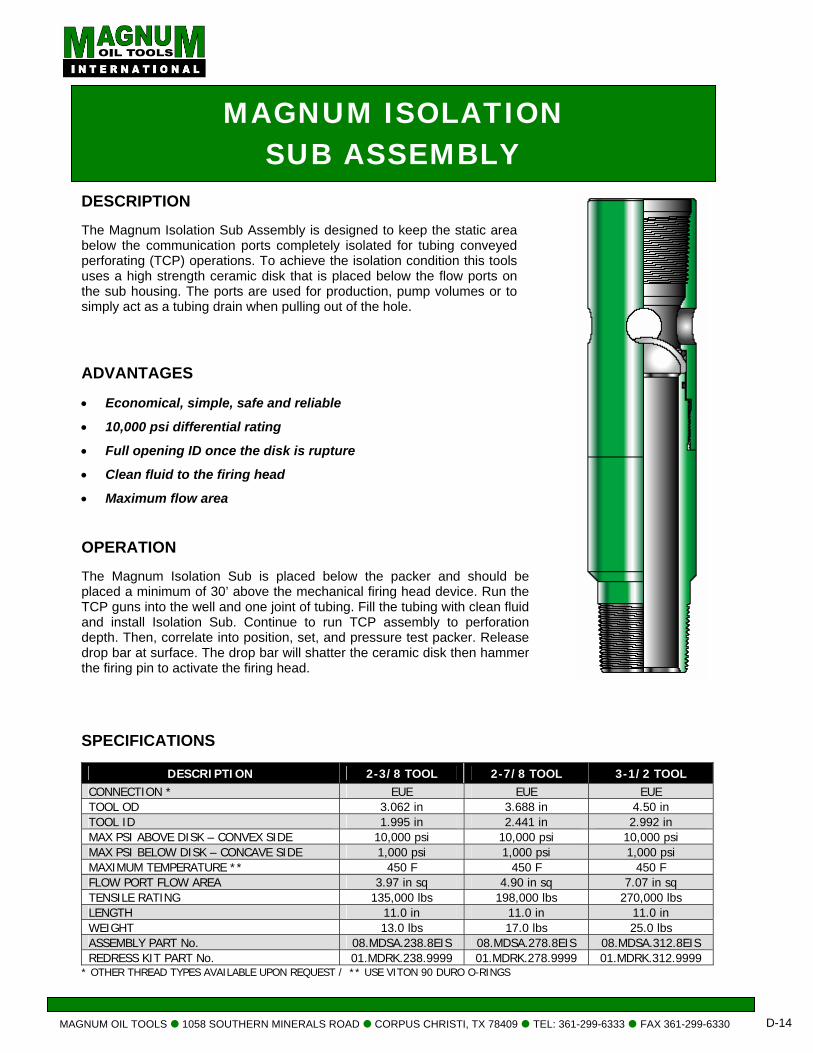
MAGNUM OIL TOOLS 1058 SOUTHERN MINERALS ROAD CORPUS CHRISTI, TX 78409 TEL: 361-299-6333 FAX 361-299-6330 D-14
MAGNUM ISOLATION SUB ASSEMBLY
DESCRIPTION The Magnum Isolation Sub Assembly is designed to keep the static area below the communication ports completely isolated for tubing conveyed perforating (TCP) operations. To achieve the isolation condition this tools uses a high strength ceramic disk that is placed below the flow ports on the sub housing. The ports are used for production, pump volumes or to simply act as a tubing drain when pulling out of the hole.
ADVANTAGES • Economical, simple, safe and reliable
• 10,000 psi differential rating
• Full opening ID once the disk is rupture
• Clean fluid to the firing head
• Maximum flow area OPERATION The Magnum Isolation Sub is placed below the packer and should be placed a minimum of 30’ above the mechanical firing head device. Run the TCP guns into the well and one joint of tubing. Fill the tubing with clean fluid and install Isolation Sub. Continue to run TCP assembly to perforation depth. Then, correlate into position, set, and pressure test packer. Release drop bar at surface. The drop bar will shatter the ceramic disk then hammer the firing pin to activate the firing head.
SPECIFICATIONS
DESCRIPTION 2-3/8 TOOL 2-7/8 TOOL 3-1/2 TOOL CONNECTION * EUE EUE EUE TOOL OD 3.062 in 3.688 in 4.50 in TOOL ID 1.995 in 2.441 in 2.992 in MAX PSI ABOVE DISK – CONVEX SIDE 10,000 psi 10,000 psi 10,000 psi MAX PSI BELOW DISK – CONCAVE SIDE 1,000 psi 1,000 psi 1,000 psi MAXIMUM TEMPERATURE ** 450 F 450 F 450 F FLOW PORT FLOW AREA 3.97 in sq 4.90 in sq 7.07 in sq TENSILE RATING 135,000 lbs 198,000 lbs 270,000 lbs LENGTH 11.0 in 11.0 in 11.0 in WEIGHT 13.0 lbs 17.0 lbs 25.0 lbs ASSEMBLY PART No. 08.MDSA.238.8EIS 08.MDSA.278.8EIS 08.MDSA.312.8EIS REDRESS KIT PART No. 01.MDRK.238.9999 01.MDRK.278.9999 01.MDRK.312.9999
* OTHER THREAD TYPES AVAILABLE UPON REQUEST / ** USE VITON 90 DURO O-RINGS
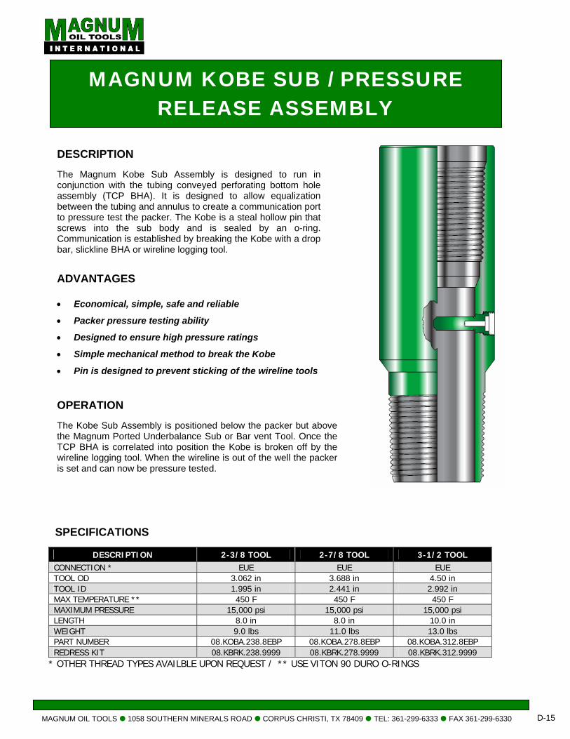
MAGNUM OIL TOOLS 1058 SOUTHERN MINERALS ROAD CORPUS CHRISTI, TX 78409 TEL: 361-299-6333 FAX 361-299-6330 D-15
MAGNUM KOBE SUB / PRESSURE RELEASE ASSEMBLY
DESCRIPTION The Magnum Kobe Sub Assembly is designed to run in conjunction with the tubing conveyed perforating bottom hole assembly (TCP BHA). It is designed to allow equalization between the tubing and annulus to create a communication port to pressure test the packer. The Kobe is a steal hollow pin that screws into the sub body and is sealed by an o-ring. Communication is established by breaking the Kobe with a drop bar, slickline BHA or wireline logging tool.
ADVANTAGES
• Economical, simple, safe and reliable
• Packer pressure testing ability
• Designed to ensure high pressure ratings
• Simple mechanical method to break the Kobe
• Pin is designed to prevent sticking of the wireline tools OPERATION The Kobe Sub Assembly is positioned below the packer but above the Magnum Ported Underbalance Sub or Bar vent Tool. Once the TCP BHA is correlated into position the Kobe is broken off by the wireline logging tool. When the wireline is out of the well the packer is set and can now be pressure tested.
SPECIFICATIONS
DESCRIPTION 2-3/8 TOOL 2-7/8 TOOL 3-1/2 TOOL CONNECTION * EUE EUE EUE TOOL OD 3.062 in 3.688 in 4.50 in TOOL ID 1.995 in 2.441 in 2.992 in MAX TEMPERATURE ** 450 F 450 F 450 F MAXIMUM PRESSURE 15,000 psi 15,000 psi 15,000 psi LENGTH 8.0 in 8.0 in 10.0 in WEIGHT 9.0 lbs 11.0 lbs 13.0 lbs PART NUMBER 08.KOBA.238.8EBP 08.KOBA.278.8EBP 08.KOBA.312.8EBP REDRESS KIT 08.KBRK.238.9999 08.KBRK.278.9999 08.KBRK.312.9999
* OTHER THREAD TYPES AVAILBLE UPON REQUEST / ** USE VITON 90 DURO O-RINGS

RELEASE TOOLS
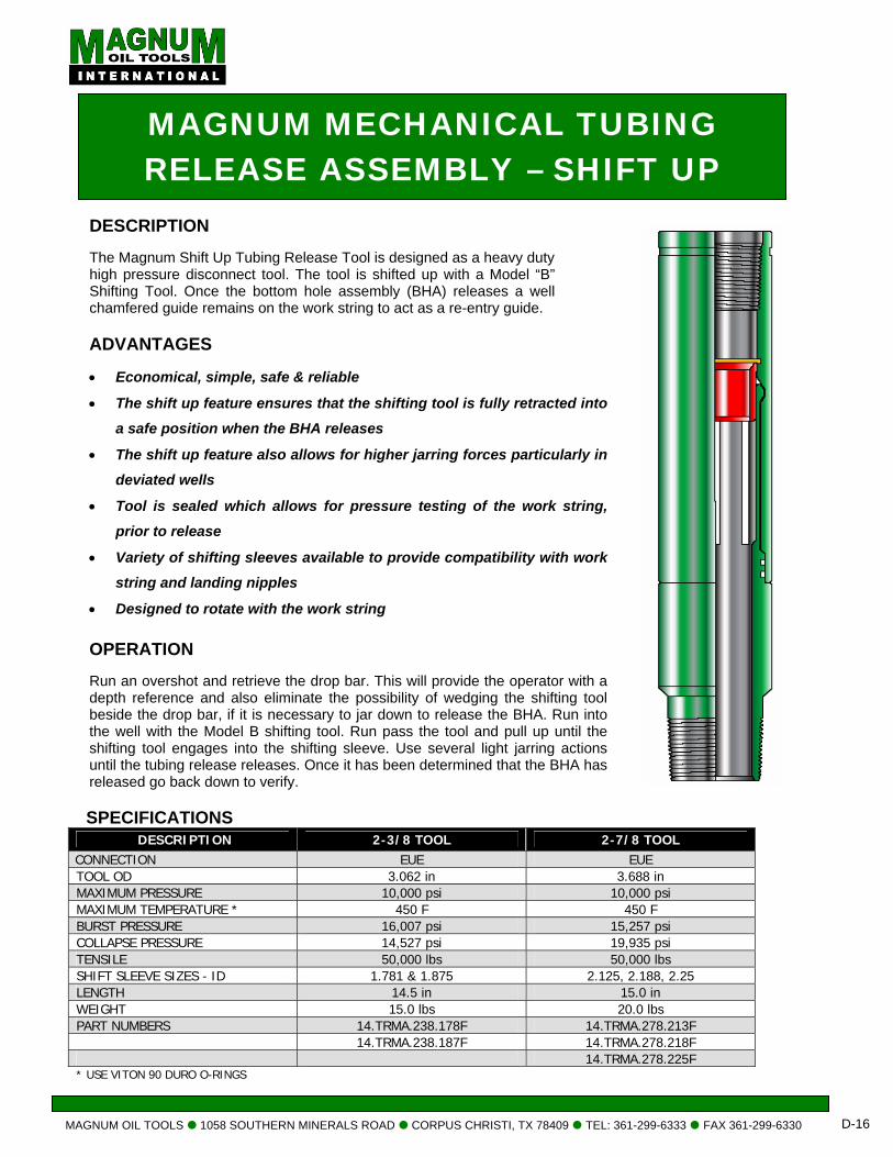
MAGNUM OIL TOOLS 1058 SOUTHERN MINERALS ROAD CORPUS CHRISTI, TX 78409 TEL: 361-299-6333 FAX 361-299-6330 D-16
MAGNUM MECHANICAL TUBING RELEASE ASSEMBLY – SHIFT UP
DESCRIPTION The Magnum Shift Up Tubing Release Tool is designed as a heavy duty high pressure disconnect tool. The tool is shifted up with a Model “B” Shifting Tool. Once the bottom hole assembly (BHA) releases a well chamfered guide remains on the work string to act as a re-entry guide.
ADVANTAGES • Economical, simple, safe & reliable
• The shift up feature ensures that the shifting tool is fully retracted into
a safe position when the BHA releases
• The shift up feature also allows for higher jarring forces particularly in
deviated wells
• Tool is sealed which allows for pressure testing of the work string,
prior to release
• Variety of shifting sleeves available to provide compatibility with work string and landing nipples
• Designed to rotate with the work string OPERATION Run an overshot and retrieve the drop bar. This will provide the operator with a depth reference and also eliminate the possibility of wedging the shifting tool beside the drop bar, if it is necessary to jar down to release the BHA. Run into the well with the Model B shifting tool. Run pass the tool and pull up until the shifting tool engages into the shifting sleeve. Use several light jarring actions until the tubing release releases. Once it has been determined that the BHA has released go back down to verify.
SPECIFICATIONS DESCRIPTION 2-3/8 TOOL 2-7/8 TOOL
CONNECTION EUE EUE TOOL OD 3.062 in 3.688 in MAXIMUM PRESSURE 10,000 psi 10,000 psi MAXIMUM TEMPERATURE * 450 F 450 F BURST PRESSURE 16,007 psi 15,257 psi COLLAPSE PRESSURE 14,527 psi 19,935 psi TENSILE 50,000 lbs 50,000 lbs SHIFT SLEEVE SIZES - ID 1.781 & 1.875 2.125, 2.188, 2.25 LENGTH 14.5 in 15.0 in WEIGHT 15.0 lbs 20.0 lbs PART NUMBERS 14.TRMA.238.178F 14.TRMA.278.213F 14.TRMA.238.187F 14.TRMA.278.218F 14.TRMA.278.225F * USE VITON 90 DURO O-RINGS
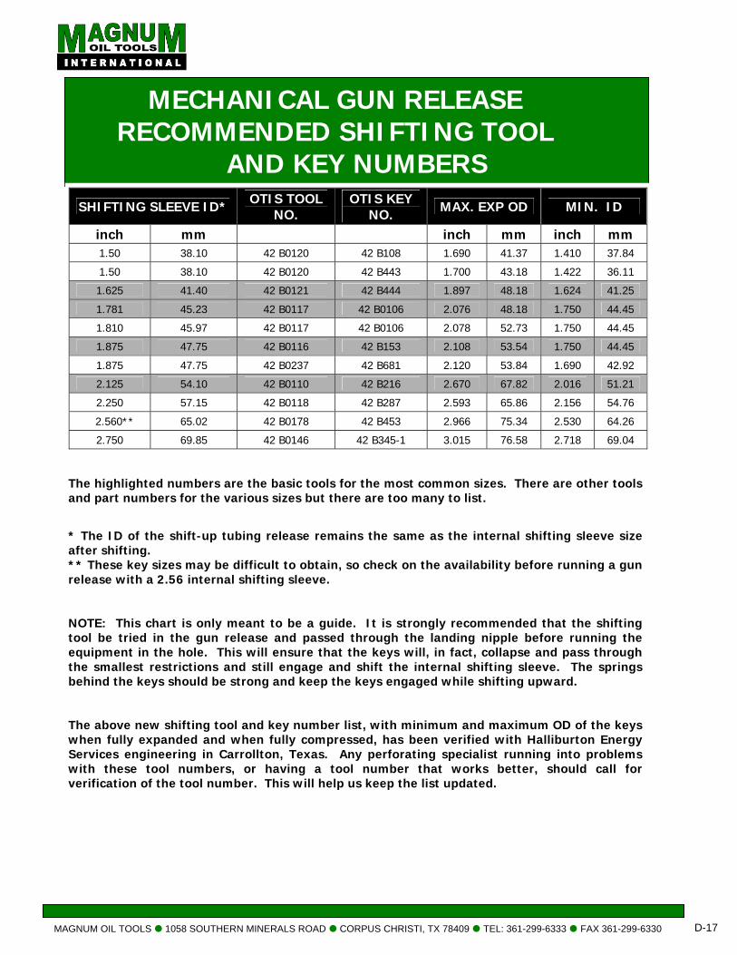
MAGNUM OIL TOOLS 1058 SOUTHERN MINERALS ROAD CORPUS CHRISTI, TX 78409 TEL: 361-299-6333 FAX 361-299-6330 D-17
MECHANICAL GUN RELEASE RECOMMENDED SHIFTING TOOL
AND KEY NUMBERS SHIFTING SLEEVE ID* OTIS TOOL
NO. OTIS KEY
NO. MAX. EXP OD MIN. ID
inch mm inch mm inch mm 1.50 38.10 42 B0120 42 B108 1.690 41.37 1.410 37.84
1.50 38.10 42 B0120 42 B443 1.700 43.18 1.422 36.11
1.625 41.40 42 B0121 42 B444 1.897 48.18 1.624 41.25
1.781 45.23 42 B0117 42 B0106 2.076 48.18 1.750 44.45
1.810 45.97 42 B0117 42 B0106 2.078 52.73 1.750 44.45
1.875 47.75 42 B0116 42 B153 2.108 53.54 1.750 44.45
1.875 47.75 42 B0237 42 B681 2.120 53.84 1.690 42.92
2.125 54.10 42 B0110 42 B216 2.670 67.82 2.016 51.21
2.250 57.15 42 B0118 42 B287 2.593 65.86 2.156 54.76
2.560** 65.02 42 B0178 42 B453 2.966 75.34 2.530 64.26
2.750 69.85 42 B0146 42 B345-1 3.015 76.58 2.718 69.04 The highlighted numbers are the basic tools for the most common sizes. There are other tools and part numbers for the various sizes but there are too many to list. * The ID of the shift-up tubing release remains the same as the internal shifting sleeve size after shifting. ** These key sizes may be difficult to obtain, so check on the availability before running a gun release with a 2.56 internal shifting sleeve. NOTE: This chart is only meant to be a guide. It is strongly recommended that the shifting tool be tried in the gun release and passed through the landing nipple before running the equipment in the hole. This will ensure that the keys will, in fact, collapse and pass through the smallest restrictions and still engage and shift the internal shifting sleeve. The springs behind the keys should be strong and keep the keys engaged while shifting upward. The above new shifting tool and key number list, with minimum and maximum OD of the keys when fully expanded and when fully compressed, has been verified with Halliburton Energy Services engineering in Carrollton, Texas. Any perforating specialist running into problems with these tool numbers, or having a tool number that works better, should call for verification of the tool number. This will help us keep the list updated.
MAGNUM OIL TOOLS 1058 SOUTHERN MINERALS ROAD CORPUS CHRISTI, TX TEL: 361-299-6333 FAX 361-299-6330 D-18
SET SCREW
SKIRT
SHEAR PIN
COLLET
ENGAGEMENT SHOULDER
KEY RETAINER
KEY SPRING
KEY RETAINER
BODY
INTERNAL SHIFTING SLEEVE
BRONZE SHEAR RING
BRONZE SHEAR RING
INTERNAL SHIFTING SLEEVE
STEAL RETAINING RING
FINGER LATCH
BALL BEARING
1. Run an over shot or pulling tool and retrieve the TCP drop bar.
NOTE: Fishing the drop bar is optional; however, fishing the drop bar will provide the operator with an exact depth reference. It will also eliminate the possibility of wedging the shifting tool beside the drop bar, if it is necessary to jar down to help release the bottom hole assembly.
2. Run in hole with the shifting tool and key for the ID size of the mechanical tubing release internal shifting sleeve.
3. Run the shifting tool through the tubing release and pick up to engage the internal shifting sleeve. 4. Jar up to shift the internal shifting sleeve. Several light jarring hits are better than a hard jarring
action. The hard jarring action can result in the shear pin shearing before the internal shifting sleeve shifts.
NOTE: Steel shear pins should be run in the place of a brass shear pin.
5. After jarring up on the internal shifting sleeve several times, go back down to verify that the tubing
release has disengaged. When it has been determined that the mechanical tubing release has released the operator can now shear the shear pin in the shifting tool.
NOTE: The keys should lock into the internal shifting sleeve. The tools cannot be removed without shearing the pin.
6. If the bottom hole assembly has not released, jar down sharply on it to help it release. If the bottom hole assembly remains intact, repeat steps 5 thru 6 until the assembly releases.
MAGNUM MECHANICAL TUBING RELEASE PROCEDURES
78409
OTIS B SHIFTING TOOL
MECH. TUBING RELEASE BALL BEARING TYPE
MECH. TUBING RELEASE FINGER TYPE
MAGNUM OIL TOOLS 1058 SOUTHERN MINERALS ROAD CORPUS CHRISTI, TX 78409 TEL: 361-299-6333 FAX 361-299-6330 D-19
NIPPLE TYPE
TUBING OD
NIPPLE BORE
PACKING BORE
NO-GO ID
SHIFTING SLEEVE ID
inch mm inch mm inch mm inch mm RECOMMENDED SIZE
OTIS “X” 2.375 60.33 1.875 47.63 1.875 47.63 NONE 1.781 OR LESS
2.875 73.02 2.313 58.75 2.313 58.75 NONE 2.250 OR LESS
OTIS “XN” 2.375 60.33 1.875 47.63 1.875 47.63 1.791 45.49 1.781 OR LESS
2.875 73.02 2.313 58.75 2.313 58.75 2.205 56.00 2.125 OR LESS
OTIS “R” 2.375 60.33 1.781 45.24 1.781 45.24 NONE 1.781 OR LESS
2.875 73.02 2.188 55.57 2.188 55.57 NONE 2.125 OR LESS
OTIS “RN” 2.375 60.33 1.781 45.24 1.781 45.24 1.640 41.65 1.640 OR LESS
2.875 73.02 2.188 55.57 2.188 55.57 2.010 51.05 1.875 OR LESS
BAKER “R” 2.375 60.33 1.781 45.24 1.781 45.24 1.728 43.89 1.640 OR LESS
2.375 60.33 1.812 46.02 1.812 46.02 1.760 44.70 1.640 OR LESS
2.375 60.33 1.875 47.63 1.875 47.63 1.822 46.28 1.781 OR LESS
2.875 73.02 2.062 52.37 2.062 52.37 1.978 50.24 1.875 OR LESS
2.875 73.02 2.250 57.15 2.250 57.15 2.197 55.80 2.125 OR LESS
BAKER “F” 2.375 60.33 1.781 45.24 1.781 45.24 NONE 1.781 OR LESS
2.375 60.33 1.812 46.02 1.812 46.02 NONE 1.812 OR LESS
2.375 60.33 1.875 47.63 1.875 47.63 NONE 1.875 OR LESS
2.875 73.02 2.062 52.37 2.062 52.37 NONE 1.875 OR LESS
2.875 73.02 2.250 57.15 2.250 57.15 NONE 2.250 OR LESS
2.875 73.02 2.312 58.72 2.312 58.72 NONE 2.250 OR LESS
REFERENCE GUIDE TO STANDARD SIZE NIPPLES
BE SURE THE WELL INSTALLATION RESTRICTIONS
“TAPER” DOWN, HAVING THE LARGEST RESTRICTION AT THE TOP AND THE SMALLEST RESTRICTION AT
THE BOTTOM OF THE WELL. -----------------------------------------------------------------------------------------------------------------------------------------------
NOTE
IF A LARGER SIZE MECHANICAL TUBING RELEASE IS ACCIDENTALLY RUN, YOU MUST USE A SLIM HOLE TOOL OR TURNED DOWN KEYS TO SHIFT THE COLLET. PLEASE CONSULT YOUR SLICKLINE
OPERATOR FOR INFORMATION AND OPERATION.

MISCELLANEOUS
TCP
MAGNUM OIL TOOLS 1058 SOUTHERN MINERALS ROAD CORPUS CHRISTI, TX 78409 TEL: 361-299-6333 FAX 361-299-6330 D-20
MAGNUM RADIOACTIVE MAKER (RA) SUB ASSEMBLY
DESCRIPTION The Magnum Radioactive Marker (RA) Sub accepts a radioactive pellet for use in depth correlation of the tubing conveyed perforating (TCP BHA). A 1.0 micro curie cobalt 60 source is used as the radioactive source.
• The RA source is easily detected by the gamma ray or gamma
ray neutron tool
• RA source is safely contained inside of a cavity on the sub
housing by a steel set screw, ensuring full recovery of the RA
source
• Full opening
OPERATION At the well site insure proper procedures and personal protective equipment (PPE) is used when installing the source into the RA Sub. Assemble the RA Sub Assembly onto the work string and record the measured depth from the top shot of the top perforating gun to the RA Sub. Trip the TCP BHA into the well. Run the gamma ray or gamma ray neutron tool and locate the RA Sub. Continue correlation log and correlate this log with the open hole gamma ray log. Make the necessary adjusts to accurately position the TCP BHA over the zone of interest. If necessary, run a confirmation correlation log.
ADVANTAGES • Economical, Simple, Safe, and Reliable
• Can be run in conjunction with all Magnum TCP firing heads
SPECIFICATIONS
DESCRIPTION 2-3/8 2-7/8 3-1/2 CONNECTION * EUE EUE EUE TOOL OD 3.062 in 3.688 in 4.50 in MINIMUM ID 1.995 in 2.441 in 2.992 in MAXIMUM PRESSURE 15,000 psi 15,000 psi 15,000 psi LENGTH 9.0 in 10.0 in 10.0 in WEIGHT 8.0 lbs 11.0 lbs 16.0 lbs PART NUMBER 10.RASC.238.8EBP 10.RASC.278.8EBP 10.RASC.312.8EBP
* OTHER THREAD TYPES AVAILABLE UPON REQUEST
MAGNUM OIL TOOLS 1058 SOUTHERN MINERALS ROAD CORPUS CHRISTI, TX 78409 TEL: 361-299-6333 FAX 361-299-6330 D-21
MAGNUMSHEAR STUD
DESCRIPTION
The Magnum Shear Stud is used in all pressure activated tubing conveyed perforating (TCP) tools. It is precisely machined to shear within +/- 5% of its rating.
ADVANTAGES • Safe, economical, simple and reliable
• Accurate to within 5%
• Single shear stud pressure setting
• Easily adapts to all pressure activated firing systems OPERATION The Shear Stud is fastened to the firing pin and positioned above the initiator. A calculated predetermined pressure is applied at surface down the work string. This pressure acts on the surface area of the firing pin. When sufficient pressure is applied the shear stud will shear and the applied pressure will hammer the firing pin into the initiator, initiating the explosive train. If tubular specifications allow, exceed the applied pressure to the shear stud rating by 10%.
SPECIFICATIONS
PART NUMBER PRESSURE RATING PART NUMBER PRESSURE RATING 11.SSTC.999.1000 1000 PSI 11.SSTC.999.7500 7500 PSI11.SSTC.999.1500 1500 PSI 11.SSTC.999.8000 8000 PSI11.SSTC.999.2000 2000 PSI 11.SSTC.999.8500 8500 PSI11.SSTC.999.2500 2500 PSI 11.SSTC.999.9000 9000 PSI11.SSTC.999.3000 3000 PSI 11.SSTC.999.9500 9500 PSI11.SSTC.999.3500 3500 PSI 11.SSTC.999.X100 10,000 PSI11.SSTC.999.4000 4000 PSI 11.SSTC.999.X105 10,500 PSI11.SSTC.999.4500 4500 PSI 11.SSTC.999.X110 11,000 PSI11.SSTC.999.5000 5000 PSI 11.SSTC.999.X115 11,500 PSI11.SSTC.999.5500 5500 PSI 11.SSTC.999.X120 12,000 PSI11.SSTC.999.6000 6000 PSI 11.SSTC.999.X125 12,500 PSI11.SSTC.999.6500 6500 PSI 11.SSTC.999.X130 13,000 PSI11.SSTC.999.7000 7000 PSI 11.SSTC.999.*
*CUSTOM RATED SHEAR STUDS CAN BE MANUFACTURED UPON REQUEST
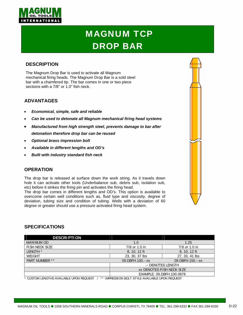
MAGNUM OIL TOOLS 1058 SOUTHERN MINERALS ROAD CORPUS CHRISTI, TX 78409 TEL: 361-299-6333 FAX 361-299-6330 D-22
MAGNUM TCP DROP BAR
DESCRIPTION
The Magnum Drop Bar is used to activate all Magnum
mechanical firing heads. The Magnum Drop Bar is a sold steel bar with a chamfered tip. The bar comes in one or two piece sections with a 7/8” or 1.0” fish neck.
ADVANTAGES
• Economical, simple, safe and reliable
• Can be used to detonate all Magnum mechanical firing head systems
• Manufactured from high strength steel, prevents damage to bar after detonation therefore drop bar can be reused
• Optional brass impression bolt
• Available in different lengths and OD’s
• Built with industry standard fish neck OPERATION The drop bar is released at surface down the work string. As it travels down hole it can activate other tools (Underbalance sub, debris sub, isolation sub, etc) before it strikes the firing pin and activates the firing head. The drop bar comes in different lengths and OD’s. This option is available to overcome certain well conditions such as, fluid type and viscosity, degree of deviation, tubing size and condition of tubing. Wells with a deviation of 60 degree or greater should use a pressure activated firing head system.
SPECIFICATIONS
DESCRIPTION MAXIMUM OD 1.0 1.25 FISH NECK SIZE 7/8 or 1.0 in 7/8 or 1.0 in LENGTH * 8, 10, 12 ft 8, 10, 12 ft WEIGHT 23, 30, 37 lbs 27, 33, 41 lbs PART NUMBER ** 09.DBFH.100.--xx 09.DBFH.150.--xx -- DENOTES LENGTH xx DENOTES FISH NECK SIZE EXAMPLE: 09.DBFH.100.0878
* CUSTOM LENGTHS AVAILABLE UPON REQUEST / ** IMPRESSION BOLT STYLE AVAILABLE UPON REQUEST
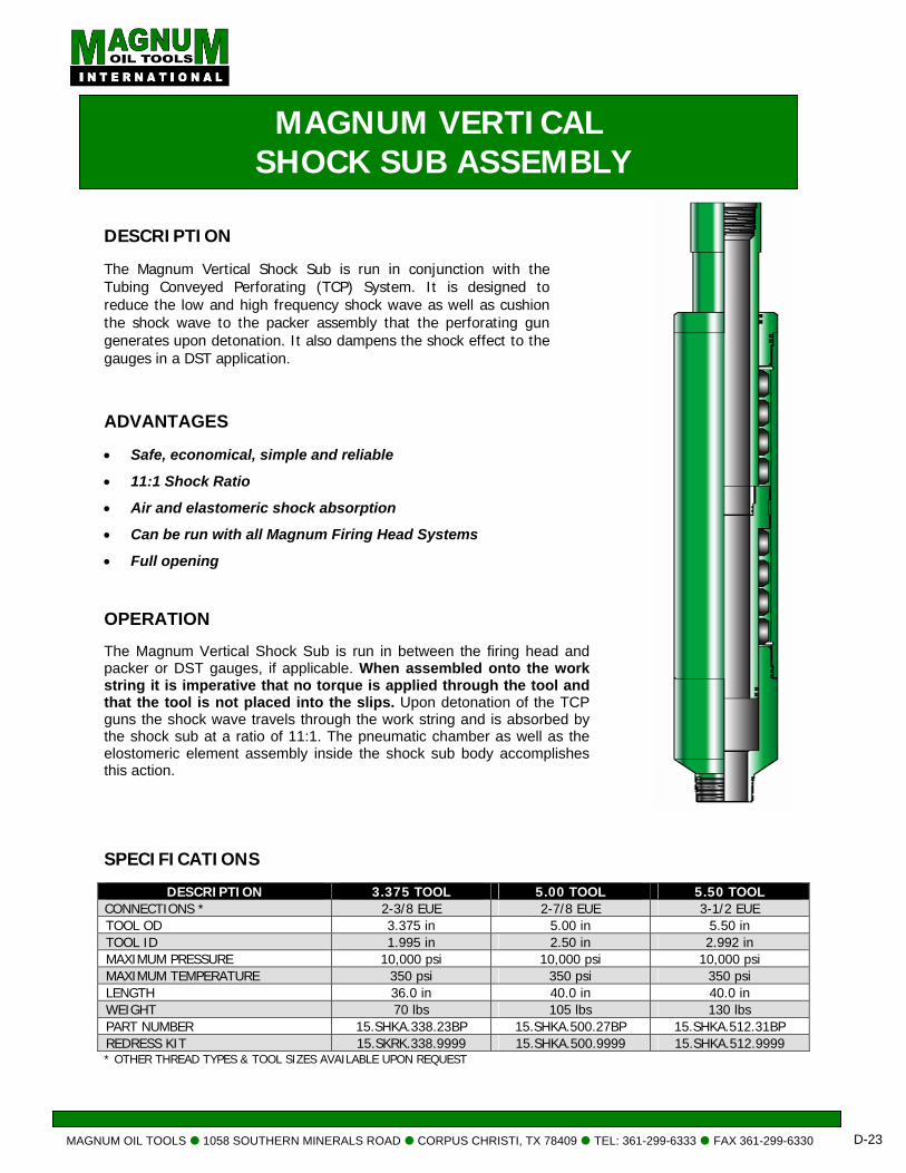
MAGNUM OIL TOOLS 1058 SOUTHERN MINERALS ROAD CORPUS CHRISTI, TX 78409 TEL: 361-299-6333 FAX 361-299-6330 D-23
MAGNUM VERTICAL SHOCK SUB ASSEMBLY
DESCRIPTION The Magnum Vertical Shock Sub is run in conjunction with the Tubing Conveyed Perforating (TCP) System. It is designed to reduce the low and high frequency shock wave as well as cushion the shock wave to the packer assembly that the perforating gun generates upon detonation. It also dampens the shock effect to the gauges in a DST application.
ADVANTAGES • Safe, economical, simple and reliable
• 11:1 Shock Ratio
• Air and elastomeric shock absorption
• Can be run with all Magnum Firing Head Systems
• Full opening OPERATION The Magnum Vertical Shock Sub is run in between the firing head and packer or DST gauges, if applicable. When assembled onto the work string it is imperative that no torque is applied through the tool and that the tool is not placed into the slips. Upon detonation of the TCP guns the shock wave travels through the work string and is absorbed by the shock sub at a ratio of 11:1. The pneumatic chamber as well as the elostomeric element assembly inside the shock sub body accomplishes this action.
SPECIFICATIONS
DESCRIPTION 3.375 TOOL 5.00 TOOL 5.50 TOOL CONNECTIONS * 2-3/8 EUE 2-7/8 EUE 3-1/2 EUE TOOL OD 3.375 in 5.00 in 5.50 in TOOL ID 1.995 in 2.50 in 2.992 in MAXIMUM PRESSURE 10,000 psi 10,000 psi 10,000 psi MAXIMUM TEMPERATURE 350 psi 350 psi 350 psi LENGTH 36.0 in 40.0 in 40.0 in WEIGHT 70 lbs 105 lbs 130 lbs PART NUMBER 15.SHKA.338.23BP 15.SHKA.500.27BP 15.SHKA.512.31BP REDRESS KIT 15.SKRK.338.9999 15.SHKA.500.9999 15.SHKA.512.9999 * OTHER THREAD TYPES & TOOL SIZES AVAILABLE UPON REQUEST
E MAGNUM A-1 HYDRAULIC
SETTING TOOLS
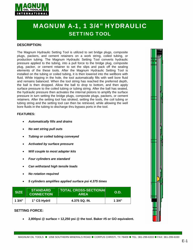
MAGNUM OIL TOOLS 1058 SOUTHERN MINERALS ROAD CORPUS CHRISTI, TX 78409 TEL: 361-
MAGNUM A-1, 1 3/4” HYDRAULIC SETTING TOOL
DESCRIPTION:
The Magnum Hydraulic Setting Tool is utilized to set bridge plugs, composite plugs, packers, and cement retainers on a work string, coiled tubing, or production tubing. The Magnum Hydraulic Setting Tool converts hydraulic pressure applied to the tubing, into a pull force to the bridge plug, composite plug, packer, or cement retainer to set the slips and pack off the sealing elements of the these tools. After the Magnum Hydraulic Setting Tool is installed on the tubing or coiled tubing, it is then lowered into the wellbore with fluid. While tripping in the hole, the tool automatically fills with well bore fluid and remains balanced. When the tool string has reached the preferred depth, the ball is then dropped. Allow the ball to drop to bottom, and then apply surface pressure to the coiled tubing or tubing string. After the ball has seated, the hydraulic pressure then activates the internal pistons to amplify the surface pressure in turn setting the bridge plugs, composite plugs, packers, or cement retainers. After the setting tool has stroked, setting the tools, the coil tubing or tubing string and the setting tool can then be retrieved, while allowing the well bore fluids in the tubing to discharge thru bypass ports in the tool.
FEATURES:
• Automatically fills and drains
• No wet string pull outs
• Tubing or coiled tubing conveyed
• Activated by surface pressure
• Will couple to most adapter kits
• Four cylinders are standard
• Can withstand high tensile loads
• No rotation required
• 5 cylinders amplifies applied surface psi 4.375 times
SETTING FORCE:
• 2,800psi @ surface = 12,250 psi @ the tool. Baker #5 or GO equivalent.
SIZE STANDARD CONNECTION
TOTAL CROSS-SECTIONALAREA O.D.
1 3/4” 1” CS Hydril 4.375 SQ. IN. 1 3/4”
299-6333 FAX: 361-299-6330 E-1

ASSEMBLY: 1. Place all parts on clean and uncluttered surface for
ease of inspection and assembly.
2. Check all parts for defects and damage. Clean all threads and seal surfaces of rust, dirt, and burrs. If a part cannot be cleaned or repaired satisfactorily, replace it and set defective part aside for rework.
3. Pre-assemble parts excluding
O-Rings to insure proper machine work. 4. Set aside proper O-Rings;
(16) 123 VITON 90 DURO for the internal sealing surface for the pistons.
(8) 118 VITON, 90 DURO for the cylinder rod.
5. High temp grease should be used during assembly.
6. Always check all sealing surfaces (pistons, o-ring grooves, and threads) are clean, free of debris and in good working condition.
7. Upper Hydraulic Mandrel (Top Sub) Part #: 40.HSTC.134.0100 Place (2) 123 O-rings on the Upper Mandrel Grease liberally with high temp assembly lube.
8. Upper Cylinder (Shear Sleeve) Part#: 40.HSTC.134.0200
Apply a thin layer of assembly lube on the inside of the Upper Cylinder to ensure o-ring damage does not occur.
Slide Upper Cylinder over the o-ring on the Upper Mandrel and continue until the Sheer screw holes align with the sheer groove.
Once in place install the four 3/8” – 16 x 3/8” brass sheer screws.
9. Piston Part #: 40.HSTC.134.0300
Install the internal (2) (118) o-rings and apply a small amount of assembly lube. Next install the exterior (2) (123) o-rings and apply assembly lube. Once the piston is properly lubricated, it can be threaded into the Upper Cylinder.
Note: The piston should be installed with the external o-rings going into the upper cylinder.
10. Cylinder Rod
Part #: 40.HSTC.134.0400 Install the (2) (123) o-rings into groove located at the bottom of the rod. Apply assembly lube Apply a generous amount of assy. lube to the sealing (polished) surface of the rod. Careful not to damage the internal o-ring of the piston, slide the rod through and thread into the Upper Hydraulic Mandrel.
11. Rod Chamber Part #: 40.HSTC.134.0500 The Rod Chamber slides over the o-rings of the Cylinder Rod and thread onto the lower portion of the piston. Apply assembly lube to the internal sealing surface to prevent o-ring damage. Once completed gently push the Rod Chamber over the Cylinder Rod, and thread onto the piston.
12. Piston Part #: 40.HSTC.134.0300 Install the internal (2) (118) o-rings and apply a small amount of assy. lube. Next install the exterior (2) (123) o-rings and apply assy. lube. Once the piston is properly lubricated, it can be threaded into the Upper Cylinder. Note: The piston should be installed with the
external o-ring going into the Upper Rod Chamber.
13. Lower Cylinder Rod
Part #: 40.HSTC.134.0400 Install the (2) (123) o-rings into groove located at the bottom of the rod. Apply assy. lube Apply a generous amount of assembly lube to the sealing (polished) surface of the rod. Careful not to damage the internal o-ring, slide the rod through the piston and thread into the Upper Cylinder Rod.
14. Lower Rod Chamber Part #: 40.HSTC.134.0500 The Rod Chamber slides over the o-rings of the Cylinder Rod and thread onto the lower portion of the piston.
MAGNUM OIL TOOLS 1058 SOUTHERN MINERALS ROAD CORPUS CHRISTI, TX 78409 TEL: 361-299-6333 FAX: 361-299-6330
E-2
Apply assembly lube to the internal sealing surface to prevent o-ring damage. Once completed gently push the Rod Chamber over the Cylinder Rod, and thread onto the piston.
15. Setting Sleeve Adapter Part#: 40.HSTC.134.0600 Install the external (2) (123) o-rings and the internal (2) (118) o-rings. Apply assembly lube to both. Thread the Setting Sleeve Adapter into the Lower Rod Chamber.
16. Connector Rod Part #: 40.HSTC.134.0700
Apply a light layer of assy. lube to the sealing (polished) surface. Slide Connector Rod through the Setting Sleeve Adapter. Then thread the Connector Rod into the Lower Cylinder Rod.
17. Tension Rod Adapter Part #: 40.HSTC.134.0800
Thread the Tension Rod Adapter into the connector
rod.
MAGNUM OIL TOOLS 1058 SOUTHERN MINERALS ROAD CORPUS CHRISTI, TX 78409 TEL: 361-299-6333 FAX: 361-299-6330
E-3
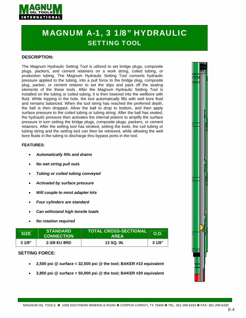
MAGNUM OIL TOOLS 1058 SOUTHERN MINERALS ROAD CORPUS CHRISTI, TX 78409 TEL: 361-
MAGNUM A-1, 3 1/8” HYDRAULIC SETTING TOOL
DESCRIPTION:
The Magnum Hydraulic Setting Tool is utilized to set bridge plugs, composite plugs, packers, and cement retainers on a work string, coiled tubing, or production tubing. The Magnum Hydraulic Setting Tool converts hydraulic pressure applied to the tubing, into a pull force to the bridge plug, composite plug, packer, or cement retainer to set the slips and pack off the sealing elements of the these tools. After the Magnum Hydraulic Setting Tool is installed on the tubing or coiled tubing, it is then lowered into the wellbore with fluid. While tripping in the hole, the tool automatically fills with well bore fluid and remains balanced. When the tool string has reached the preferred depth, the ball is then dropped. Allow the ball to drop to bottom, and then apply surface pressure to the coiled tubing or tubing string. After the ball has seated, the hydraulic pressure then activates the internal pistons to amplify the surface pressure in turn setting the bridge plugs, composite plugs, packers, or cement retainers. After the setting tool has stroked, setting the tools, the coil tubing or tubing string and the setting tool can then be retrieved, while allowing the well bore fluids in the tubing to discharge thru bypass ports in the tool.
FEATURES:
• Automatically fills and drains
• No wet string pull outs
• Tubing or coiled tubing conveyed
• Activated by surface pressure
• Will couple to most adapter kits
• Four cylinders are standard
• Can withstand high tensile loads
• No rotation required
SETTING FORCE:
• 2,500 psi @ surface = 32,500 psi @ the tool; BAKER #10 equivalent
• 3,850 psi @ surface = 50,000 psi @ the tool; BAKER #20 equivalent
SIZE STANDARD CONNECTION
TOTAL CROSS-SECTIONAL AREA O.D.
3 1/8” 2-3/8 EU 8RD 13 SQ. IN. 3 1/8”
299-6333 FAX: 361-299-6330 E-4
• 4
ASSEMBLY: 1. Place all parts on clean and uncluttered surface for
ease of inspection and assembly.
2. Check all parts for defects and damage. Clean all threads and seal surfaces of rust, dirt, and burrs. If a part cannot be cleaned or repaired satisfactorily, replace it and set defective part aside for rework.
3. Pre-assemble parts excluding
O-Rings to insure proper machine work. 4. Set aside proper O-Rings;
(3) 224 VITON for the internal sealing surface for the pistons. (6) 229 VITON for the subs
5. High temp grease should be used during assembly.
6. Always check all sealing surfaces (pistons, o-ring grooves, and threads) are clean, free of debris and in good working condition.
7. Upper Hydraulic Mandrel (Top Sub) Part #: 40.HSTC.238.0100 Place (1) 229 O-ring on the Upper Mandrel Grease liberally with high temp assembly lube.
8. Upper Cylinder (Shear Sleeve) Part#: 40.HSTC.238.0200
Apply a thin layer of assembly lube on the inside of the Upper Cylinder to ensure o-ring damage does not occur.
Slide Upper Cylinder over the o-ring on the Upper Mandrel and continue until the Sheer screw holes align with the sheer groove.
Once in place install the four 3/8” – 16 x 3/8” brass sheer screws.
9. Piston Part #: 40.HSTC.238.0300
Install the internal (224) o-ring and apply a small amount of assembly lube. Next install the exterior (229) o-ring and apply assembly lube. Once the piston is properly lubricated, it can be threaded into the Upper Cylinder. Note: The piston should be installed with the
external o-ring going into the upper cylinder.
10. Cylinder Rod
Part #: 40.HSTC.238.0400 Install the (229) o-ring into groove located at the bottom of the rod. Apply assembly lube Apply a generous amount of assembly lube to the sealing (polished) surface of the rod. Careful not to damage the internal o-ring of the piston, slide the rod through and thread into the Upper Hydraulic Mandrel.
11. Rod Chamber Part #: 40.HSTC.238.0500 The Rod Chamber slides over the o-ring of the Cylinder Rod and thread onto the lower portion of the piston. Apply assembly lube to the internal sealing surface to prevent o-ring damage. Once completed gently push the Rod Chamber over the Cylinder Rod, and thread onto the piston.
12. Piston Part #: 40.HSTC.238.0300 Install the internal (224) o-ring and apply a small amount of assembly lube. Next install the exterior (229) o-ring and apply assembly lube. Once the piston is properly lubricated, it can be threaded into the Upper Cylinder. Note: The piston should be installed with the
external o-ring going into the Upper Rod Chamber.
13. Lower Cylinder Rod
Part #: 40.HSTC.238.0400 Install the (229) o-ring into groove located at the bottom of the rod. Apply assembly lube Apply a generous amount of assembly lube to the sealing (polished) surface of the rod. Careful not to damage the internal o-ring, slide the rod through the piston and thread into the Upper Cylinder Rod.
14. Lower Rod Chamber Part #: 40.HSTC.238.0500 The Rod Chamber slides over the o-ring of the Cylinder Rod and thread onto the lower portion of the piston. Apply assembly lube to the internal sealing surface to prevent o-ring damage.
MAGNUM OIL TOOLS 1058 SOUTHERN MINERALS ROAD CORPUS CHRISTI, TX 78409 TEL: 361-299-6333 FAX: 361-299-6330 E-5
Once completed gently push the Rod Chamber over the Cylinder Rod, and thread onto the piston.
15. Setting Sleeve Adapter Part#: 40.HSTC.238.0600 Install the external (229) o-ring and the internal (224) o-ring. Apply assembly lube to both. Thread the Setting Sleeve Adapter into the Lower Rod Chamber.
16. Connector Rod Part #: 40.HSTC.238.0700
Apply a light layer of assembly lube to the sealing (polished) surface. Slide Connector Rod through the Setting Sleeve Adapter. Then thread the Connector Rod into the Lower Cylinder Rod.
17. Tension Rod Adapter Part #: 40.HSTC.238.0800
Thread the Tension Rod Adapter into the connector
rod.
MAGNUM OIL TOOLS 1058 SOUTHERN MINERALS ROAD CORPUS CHRISTI, TX 78409 TEL: 361-299-6333 FAX: 361-299-6330 E-6