Compiling from Haste to CDFG: a front end for an ... · a front end for an asynchronous circuit...
97
Compiling from Haste to CDFG: a front end for an asynchronous circuit synthesis system Jonas Braband Jensen Johan Sebastian Rosenkilde Nielsen Supervisors: Sune F. Nielsen, Christian W. Probst, Jens Sparsø Kongens Lyngby 2007 IMM-BSC-2007-08
Transcript of Compiling from Haste to CDFG: a front end for an ... · a front end for an asynchronous circuit...

Compiling from Haste to CDFG:a front end for an asynchronous circuit
synthesis system
Jonas Braband Jensen
Johan Sebastian Rosenkilde Nielsen
Supervisors: Sune F. Nielsen, Christian W. Probst, Jens Sparsø
Kongens Lyngby 2007
IMM-BSC-2007-08

Technical University of Denmark
Informatics and Mathematical Modelling
Building 321, DK-2800 Kongens Lyngby, Denmark
Phone +45 45253351, Fax +45 45882673
www.imm.dtu.dk
iii
Abstract
We have implemented a compiler from the high-level asynchronous hardware pro-gramming language Haste into a control-data flow graph, or CDFG. The CDFG rep-resentation is used in the literature for scheduling and resource sharing optimisationsin hardware synthesis.
There exists a multitude of CDFG dialects in the literature, none of them directlysuitable for representing Haste, which has CSP-like parallel processes and channelcommunication. Therefore we have designed our own dialect, and we compare it tothree prominent dialects from the literature.
The compiler translates a non-trivial subset of Haste into this dialect using the in-termediate language Hurry as a stepping stone. In designing Hurry, our goal was tosimplify Haste to the greatest extent possible without losing descriptive power or in-troducing inefficiencies. The resulting reduction in complexity makes Hurry suitablenot just for this project, but any system analysing Haste code should consider usingHurry as an intermediate representation.
We have implemented a simulator for our CDFG dialect, and therefore a simulatorfor Haste. This enabled us to test the compiler with both real-world programs andunit tests that exercise corner cases of the language.
We have looked the possibility of performing optimisations on a CDFG, and wedescribe problems that arise when we impose no well-formedness restrictions on it.
iv
Resume
Vi har implementeret en compiler, der oversætter fra det høj-niveau, asynkronehardware-programmeringssprog Haste til en control-data flow graph, eller CDFG.CDFG-repræsentationen er i litteraturen ofte brugt til schedulerings- og ressourcede-lingsoptimeringer for hardwaresyntese.
Der er en mængde af CDFG-dialekter i litteraturen, men ingen af dem er direktebrugbare til at beskrive Haste, der har CSP-lignende parallelle processer og kanal-kommunikation. Derfor har vi designet vores egen dialekt, og vi sammenligner dennemed tre prominente dialekter fra litteraturen.
Compileren oversætter en signifikant del af Haste til denne dialekt ved hjælp af etmellemliggende sprog Hurry. Under designet af Hurry var malet at simplificere Hastemest muligt uden at miste udtrykskraft eller introducere ineffektive konstruktioner.Den endelige reduktion i kompleksitet betyder, at Hurry ikke blot er passende fordette projekt, men at ethvert projekt, der analyserer Haste kode, bør overveje atbruge Hurry som et mellemliggende sprog.
Vi har implementeret en simulator for vores CDFG-dialekt og dermed en simulatorfor Haste. Dette har gjort os i stand til at teste vores compiler med bade virkeligeprogrammer og med komponent-tests, der afprøver sprogets randtilfælde.
Vi har undersøgt muligheden for at optimere pa CDFG’er, og vi beskriver problemerder opstar, nar de ikke er underlagt noget krav om velformethed.

v
Preface
This thesis was prepared at the institute of Informatics and Mathematical Modellingat the Technical University of Denmark in the period of January through June 2007.It was part of the requirements for acquiring the B.Sc. degree in engineering.
We would like to thank our three supervisors Sune F. Nielsen, Christian W. Probst,and Jens Sparsø for their guidance and advice during the project. We would also liketo thank the people of the Language Based Technology and System-on-Chip groupsfor their advice and for generously making room, computers, and coffee available.
Kongens Lyngby, June 2007
Jonas Braband JensenJohan Sebastian Rosenkilde Nielsen

vi CONTENTS
Contents
1 Introduction 11.1 Organisation of this report . . . . . . . . . . . . . . . . . . . . . . . . . 31.2 Related work . . . . . . . . . . . . . . . . . . . . . . . . . . . . . . . . 3
2 Introduction to Haste 52.1 Factorial in Haste . . . . . . . . . . . . . . . . . . . . . . . . . . . . . . 62.2 Internal Representation . . . . . . . . . . . . . . . . . . . . . . . . . . 7
3 Compiler design 8
4 The intermediate language Hurry 134.1 Factorial in Hurry . . . . . . . . . . . . . . . . . . . . . . . . . . . . . 144.2 Internal representation . . . . . . . . . . . . . . . . . . . . . . . . . . . 164.3 Translation from Haste to Hurry . . . . . . . . . . . . . . . . . . . . . 174.4 Limitations in Hurry and the translation . . . . . . . . . . . . . . . . . 18
5 Control-data flow graphs 205.1 CDFG nodes . . . . . . . . . . . . . . . . . . . . . . . . . . . . . . . . 215.2 Factorial in CDFG . . . . . . . . . . . . . . . . . . . . . . . . . . . . . 275.3 Observable behaviour . . . . . . . . . . . . . . . . . . . . . . . . . . . 295.4 Internal representation . . . . . . . . . . . . . . . . . . . . . . . . . . . 32
6 Translation from Hurry to CDFG 336.1 Base language . . . . . . . . . . . . . . . . . . . . . . . . . . . . . . . . 346.2 I/O statements . . . . . . . . . . . . . . . . . . . . . . . . . . . . . . . 416.3 Subroutines . . . . . . . . . . . . . . . . . . . . . . . . . . . . . . . . . 42
7 Design choices 457.1 Forking of values . . . . . . . . . . . . . . . . . . . . . . . . . . . . . . 457.2 Constants . . . . . . . . . . . . . . . . . . . . . . . . . . . . . . . . . . 467.3 Complexity of nodes . . . . . . . . . . . . . . . . . . . . . . . . . . . . 467.4 Representing channel communication . . . . . . . . . . . . . . . . . . . 477.5 Representing procedures . . . . . . . . . . . . . . . . . . . . . . . . . . 487.6 Representing parallel read/write . . . . . . . . . . . . . . . . . . . . . 50
8 Transformations on the CDFG 528.1 Well-formedness . . . . . . . . . . . . . . . . . . . . . . . . . . . . . . 528.2 Implemented optimisations . . . . . . . . . . . . . . . . . . . . . . . . 56
9 Tests 609.1 Larger programs . . . . . . . . . . . . . . . . . . . . . . . . . . . . . . 629.2 CDFG simulator . . . . . . . . . . . . . . . . . . . . . . . . . . . . . . 62

CONTENTS vii
10 Future work 64
11 Conclusion 66
A Malformed CDFGs 67
B Further details on MapStructure 75B.1 Explaining the VoidForks specification . . . . . . . . . . . . . . . . . . 75B.2 Explaining the SimplifySlice specification . . . . . . . . . . . . . . . . 77B.3 Calling MapStructure . . . . . . . . . . . . . . . . . . . . . . . . . . . 78
C Guide to the source code 80C.1 Running the compiler . . . . . . . . . . . . . . . . . . . . . . . . . . . 80C.2 Exploring the source files . . . . . . . . . . . . . . . . . . . . . . . . . 82
D Limitations in the compiler 86D.1 Limitations in the translation from Haste to Hurry . . . . . . . . . . . 86D.2 Limitations in the translation from Hurry to CDFG . . . . . . . . . . 87
E Details on Hurry 88
References 89


1
1 Introduction
The purpose of this project is to compile source code written in the high-level hard-ware programming language Haste into a control-data flow graph, or CDFG. This canbe used as the first step in a hardware synthesis system that produces an integratedcircuit from Haste source code.
Unlike traditional software compilers, much potential optimisation for a hardwarecompiler lies in making the code more parallel. One approach to this is to transformthe code into some CDFG dialect because dependencies between operations becomevery clear in this form. The CDFG can then be scheduled as described in Sune F.Nielsen’s research [Nielsen05] and [Nielsen07] and synthesised into a hardware circuit.The main contribution of this project is to allow generation of large CDFGs in orderto benchmark that scheduling. Until now, the scheduling algorithms have only beenbenchmarked with CDFGs that were small enough to construct by hand, but ourcompiler will allow large and complex CDFGs to be generated from readable andmaintainable Haste source code.
x
BR0 1
b
0 1ME
+
x’
1
Figure 1.1: Simple example of a CDFG.

2 Introduction
A fragment of a CDFG is shown in figure 1.1 on the preceding page. That examplecorresponds to the code:
if b then
x := x + 1
fi
Execution starts by placing the initial values of x and b on the top edges. The valueswill flow in the direction of the arrows until they reach one of the nodes. Unlikea traditional data flow graph, a CDFG also models control flow. The branch (BR)node will move the data from the topmost input to either the left or right output,depending on the value of the control input on the left. The merge (ME) node willmove data from either the left or right input to the bottom output, depending on thevalue of its control input. Eventually there will be data on the bottom edge, whichwill represent the new value of x.
Haste is special among hardware programming languages in that it compiles to asyn-chronous circuits. While most microprocessors and other complex integrated circuitsin widespread use are synchronised globally by a clock signal that ticks millions orbillions of times per second, an asynchronous circuit attempts to start operations assoon as possible rather than waiting for the clock signal. In exchange for the clock,it uses two-way handshakes between components (such as arithmetic operators) sothat components can let each other know when they are ready to exchange data.
Although asynchronous circuits have been around since the fifties, they quickly fellout of practical use after synchronous circuits surpassed them in terms of speed andchip area [Sparsø01]. However, as clock frequencies are increasing increasing, chipdesigners are experiencing difficulties distributing the clock over the entire chip areawithout destroying its shape and level [Sparsø01]. This is spurring a renewed interestin asynchronous chip design, creating a demand for better synthesis tools.
The Haste programming language by Handshake Solutions is the current state ofthe art in high-level programming of asynchronous circuits. Their Haste compiler issyntax-directed, which is another way of saying that it does not optimise the code.Rather than viewing this as a shortcoming, they consider it a feature, as the pro-grammer can predict almost exactly how his code will be compiled and does not haveto fear that the compiler is working against his own optimisations. This can be im-portant when writing the performance-critical inner loops, but the programmer maynot have time to optimise the rest of the program so meticulously. Even if he coulddo that, the code would become unreadable and unmaintainable. These are the samereasons why modern software compilers are optimising.
More information about asynchronous circuits can be found in [Sparsø01] and theywill not be discussed further in this report.
The aim of this project is to develop a working compiler from a non-trivial subset ofHaste to a CDFG. As CDFG is a class of computation representations, it is necessary

1.1 Organisation of this report 3
to define a sensible dialect that is similar to what is generally found in the literature,along with any necessary extensions for special Haste constructs. The dialect shouldbe kept small and the semantics simple. The aim of the CDFG is to reveal possibleparallelisms in the computation; the dialect of CDFG and the compilation of theHaste constructs should reflect this. The resulting CDFG is to be used for schedulingfollowed by some compilation to hardware, so it is also important to not introduceinefficiencies with regard to area, speed, and energy consumption, which cannot beeasily removed. Finally, we wish to look at the prospects of optimising the CDFGbefore scheduling.
1.1 Organisation of this report
Section 2 introduces the most important features of Haste. This is followed by section3, which gives an overview of what we have implemented and what it can be usedfor. Sections 4 and 5 describe two languages that we have designed for this project:Hurry is our simplified internal representation of Haste, and CDFG is our outputlanguage. Section 6 details how we translate from Hurry to CDFG, followed by adiscussion on the choices we made as we designed CDFG in section 7. The designsection follows the translation because it is important to understand how our designis used when comparing with alternatives.
Section 8 discusses what can be done to transform a CDFG into one with identicalbehaviour but better performance. It turns out that even the most intuitively correcttransformations can only be done under certain restrictions. The rest of the sectiondescribes a number of optimisations that we have implemented, that should work un-der those restrictions. Section 9 describes how we have tested our code and describesa simulator for CDFG that we have written for testing purposes. We end the reportwith a discussion of possibilities for future work building on this project in section10 and a conclusion in section 11.
Appendix A shows CDFGs that each violate one of the well-formedness rules intro-duced in section 8.1. Appendix B thoroughly describes a sophisticated transformationfunction that we have implemented and used for several optimisations as describedin section 8.2.3. Appendix C is a guide to compiling and running the programs wehave produced in this project. Appendix D summarises all the Haste language fea-tures that we do not support. Appendix E contains details on Hurry that were notnecessary for understanding the rest of this report.
1.2 Related work
The control-data flow graph, or CDFG, is a model of computation that has beenused for a variety purposes since the seventies. It can model hardware, software ormathematics on both high and low levels of abstraction, and it can be extended with

4 Introduction
concepts such as recursive function calls or infinite queues. A summary of variousCDFG models can be found in [Dennis84].
The idea of scheduling a hardware description for higher performance using a CDFGhas been explored many times for synchronous circuits [DeMicheli94]. [Stok91] brieflyoutlines how to extract a CDFG from a behavioural language, then develops algo-rithms for assigning and scheduling in order to share the hardware for arithmeticoperators. Starting from a subset of VHDL, [Brage93] describes a complete imple-mentation of a high-level synthesis system, which uses CDFGs as an intermediatelanguage but does not exploit the scheduling possibilities offered by the CDFG.
In his Ph.D. thesis [Nielsen05] and a subsequent paper [Nielsen07], Sune F. Nielsenhas developed a scheduler for asynchronous circuits based on heuristic techniquesknown from Operations Research. This tool inputs an acyclic CDFG and producesoutput in the Balsa [Bardsley98] hardware description language. The Balsa codecan then be synthesised with the available syntax-directed tools, thereby producing ahardware circuit. The main purpose of our project is to generate such a CDFG froma program written in the Haste language [Peeters05], enabling direct comparison ofthe syntax-directed translation of the Haste source with the scheduled circuit.
When Balsa was developed, the most widespread high-level asynchronous hardwaredescription language was Tangram, developed by Philips Research. Balsa attemptedto be an open source and improved version of Tangram, extending it in some areasand simplifying it in others. The Tangram language has since gained many of thefeatures that were introduced in Balsa, and its name has been changed to Haste.Haste is currently the most popular language for asynchronous hardware description,and future versions of the tool described in [Nielsen07] will output to Haste. Usingthe tool produced in this project, it will also be able to input from Haste.

5
2 Introduction to Haste
This section introduces the parts of Haste that are required for understanding therest of this report, and how we represent Haste in our compiler. Further details aboutthe language can be found in [Peeters05]. If you already know Haste, you may skipto section 2.2.
Haste has very low-level constructs for writing optimal code when performing syntax-directed compilation. Still, its constructs are well-behaved, which makes it suitablefor optimisations performed by an automated tool.
It is a structured imperative language that can be programmed much like C or Pascal.Because it targets hardware, it is fundamentally different from software languages;for example, function calls cannot be recursive because there is no stack. There arealso benefits, particularly in describing parallel processes and communication betweenthem.
Two statements S1 and S2 can be composed as S1;S2, which will wait for S1 to finishbefore executing S2. Alternatively, one may write S1||S2 to execute both statementsin parallel. Taking its inspiration from CSP, the principal way of communicatingbetween processes is over channels via the send statement (channel ! expression)and receive statement (channel ? variable). The statement (c!x || c?y) is thusequivalent to (y := x)
The send and receive statements are also used for synchronisation because they willwait until there is a process ready to communicate at the other end of the channel. Forapplications where the only purpose of the channel communication is to synchronise,the special value ~ is used to denote “no data”. When there are several pending sendstatements on a channel, it is arbitrary which of them communicates with a pendingreceive and likewise if there are several pending receive statements.
In most programming languages, integer types are specified by their bit width. Hastebreaks with this tradition by defining them by their range instead. An 8-bit unsignedinteger thus has the type [0..255], but it is possible to restrict the types to unalignedranges such as [100..103]. Although the four values in that range could be representedwith only two bits, Haste still allocates seven bits for that type. The advantage ofhaving range types is that the code can be checked for integer overflows at compile-time in many cases.
The concept of tuples is also important. They are known from functional program-ming languages and are comparable to a struct from C. For example, <<2,3>> is atuple expression. It has the type <<[2..2], [3..3]>> and is represented by thelittle-endian concatenation of the bits representing 2 and 3; i.e. 1011. Tuple ele-ments can themselves be tuples, and variables can have tuple types. Channels orvariable references can also be tuples, as in <<a,b>> ! <<2,3>>, which is equivalentto a!2 || b!3 as we will see later.

6 Introduction to Haste
Because the compiler from Handshake Solutions is syntax-directed, a statement suchas
x := x+1 ; y := y+1
will generate quite inefficient code. It will implement two adders on the physicalchip even though these are never used at the same time. Changing the sequentialcomposition to parallel composition would increase speed.
Alternatively, we could optimise for a smaller area by only implementing the incre-mentation once and then calling it in sequence. Haste lets us do this by declaring aprocedure as in:
begin
inc :proc(v :var int ff).
v := v+1
|
inc(x) ; inc(y)
end
This saves the cost of implementing incrementation twice, but it adds the cost of aprocedure call. A procedure in Haste is compiled only once and can then be calledfrom many places, but only from one place at a time. Procedure arguments can beboth variables, channels, or even references to other procedures. Haste also has theconcept of a function, which is like a procedure with a single return value and no sideeffects.
A Haste program is a collection of files, each exporting exactly one procedure orfunction. A program can have exactly one main procedure or function.
2.1 Factorial in Haste
Figure 2.1 on the next page shows a typical Haste program implementing a loopcalculating the factorial function.
It starts by defining int to be a shorthand for the 32-bit unsigned integer type. Line3 declares the main procedure named fact. It takes two channel parameters, wherethe first is restricted to receiving, and the second is restricted to sending. Note thatthe parameters are not values, but instead they are channels that can be used toexchange values with the caller.
The forever do loop that encapsulates the rest of the procedure will never terminate.Instead it will wait to receive a number on the input channel in line 7, calculate thefactorial function in the loops in lines 9 through 12, send the result to the outputchannel in line 13 and then start over.

2.2 Internal Representation 7
1 int = type [0..2^32-1] &
2
3 fact : main proc (in?chan int & out!chan int).
4 begin x,y :var int ff
5 |
6 forever do
7 in ? x
8 ; y := 1
9 ; do x > 1 then
10 y := y * x
11 ; x := x - 1
12 od
13 ; out ! y
14 od
15 end
Figure 2.1: The factorial function in Haste
2.2 Internal Representation
As described in [Appel98], the first step in a compiler is to build an in-memory syntaxtree from the source file. Our compiler follows the standard practice of using lexerand parser generators for this. After being parsed to a syntax tree, the source file isno longer used; all further work is done on internal representations.
A snippet of Haste source code with the corresponding syntax tree is shown in fig-ure 2.2 on the following page. The style of the lines of the tree show which syntaxgroup the sub-elements must belong to; e.g. the sub-elements of the binary operator+ must be expressions.
We can parse the entire Haste language except for the compiler directives describedin [Peeters05, section 3.6], which are only used for optimisation and debugging. Pre-processor support, as described in [Peeters05, section 3.5], can be enabled by filteringthe input file with the C preprocessor before compiling.
All Haste syntax can thus be converted into a syntax tree. This does not mean thatour compiler supports the entire Haste language, because the stages after parsingonly supports a subset of Haste. An overview of the limitations is given in section 3and summarised in appendix D.

8 Compiler design
forever do
in ? x;
x := x + 1;
out ! x
od
=⇒
Figure 2.2: An example of a syntax tree used to represent Haste internally.
3 Compiler design
This section explains our overall approach to compiling a Haste program into a CDFG.We also outline how this CDFG could be translated back into hopefully more efficientHaste code.
First of all, we have limited ourselves to supporting a subset of Haste. This is mostlybecause we want to stay within the time frame of the project and because someconstructs are not very naturally expressed in CDFG form. Specifically, input/outputcode in a CDFG does not enjoy the same increase in parallelism that data processingdoes, as we discuss in section 5.3. The major language features missing in our compilerare arrays, non-handshaking I/O (wires), and simultaneous read/write of variables.A complete list can be found in appendix D.
Since we are implementing a subset of Haste that cannot do I/O directly to wires,it cannot usefully implement the main procedure. Instead, we envision that userswill write the main procedure in syntax-directed Haste and from there call into oneor more procedures of optimised Haste that has been generated with our compiler’sCDFG output as an intermediate step. The syntax-directed program is then anexternal actor from our programs point of view, that interface with the optimisedprogram by calling a procedure and waiting for it to return, or by calling a procedureand communicating on the channels passed to it. This is illustrated in figure 3.1 onthe next page.
Figure 3.2 on the facing page shows how we envision that the optimised code from fig-ure 3.1 will be compiled from regular Haste code. Each step in the figure is explainedhere:
1. Because the Haste language contains a great amount of syntactic sugar and

9
Figure 3.1: The encapsulation of our optimised code inside the main program. Theoptimised code does not interact with the surrounding environment.
Figure 3.2: Overview of the steps in compilation from Haste to optimised Haste.

10 Compiler design
redundant constructions, our compiler translates the Haste source code into anintermediate language that we have dubbed Hurry. This language is similar toHaste, but it also has some features in common with CDFG. The next sectiondescribes Hurry in greater detail.
2. The Hurry code is translated into a CDFG in a syntax-directed manner. Thisstep does not attempt to generate very efficient code when that goal conflictswith the simplicity of its implementation.
3. The CDFG is optimised by a series of transformations that each turn a CDFGinto a more efficient one. This includes removal of nodes that have no influenceon the CDFG semantics and substitution of simple nodes for complex ones.This step repairs most inefficiencies introduced by the translation to CDFG,and it also catches inefficiencies that were already present in the original Hastesource.
4. The CDFG can now be given to the tool described in [Nielsen05] and [Nielsen07],whose purpose is to determine which operations should be executed on sharedhardware in order to optimise for a desired trade-off between speed and circuitarea. It analyses the information about data dependencies and parallelisminherent in the CDFG, then performs the scheduling based on heuristic guesses.
5. After scheduling, the code needs to be turned back into a form that can becompiled to hardware. The tool from [Nielsen07] currently outputs to Balsa[Bardsley98], but future versions will output to Haste or Hurry. Using Hasteagain as output language may seem strange, but is possible because of Haste’slow-level constructs, suitable for syntax-directed compilation. It would also bepossible to transform the CDFG directly into a circuit of handshake compo-nents.
Figure 3.3 on the next page shows what we have actually implemented. In additionto the path from Haste source code to CDFG source code we have added severalother output formats to aid in debugging and visualising the code:
• We have written a simulator that inputs a CDFG program and a list of inputdata. When the simulation has either terminated or deadlocked, it returnsthe program’s output. By comparing this output to the Handshake Solutionssimulator we can test the correctness of our translation to CDFG.
• A CDFG can be dumped to Graphviz format, which is an annotated descriptionof a directed graph that can be rendered as a PDF document. CDFG imagesin this report, though in most cases rearranged by hand for demoting detailsirrelevant to the respective discussion, have been generated in this manner. Oursource archive also contains a PDF for each of our unit tests.
• The CDFG program can be deparsed to or parsed from a simple text format.To aid users of this compiler in parsing such text files, we have also implemented

11
Haste source
In-memory Haste
In-memory Hurry
In-memory CDFG Hurry source
CDFG source Graphviz sourceSimulation
output
CDFGC data
structurePDF drawing
Figure 3.3: Overview of the data forms used in our compiler. The arrows indicatewhich translations we have implemented.

12 Compiler design
a parser in the C programming language. By using or imitating one of theseparsers, our CDFG source format can easily be parsed from other programminglanguages.
• Haste code can be deparsed from our in-memory representation back to a sourcefile. We use this to test the correctness of our parser.
• Hurry can be turned back into Haste. We use this to test the correctness of thetranslation to Hurry.
• Hurry can be deparsed to a text file, which we have used in debugging thetranslation to Hurry. If a CDFG scheduler used Hurry as its output language,we would also need to implement a Hurry parser.
We have also written a unit test framework that ties the above-mentioned toolstogether with a collection of Haste files. These tools are discussed further in section9.

13
4 The intermediate language Hurry
The Haste language offers the programmer a great deal of syntactic sugar and compile-time type checking. Although these features make Haste code more readable andmaintainable, it complicates the compiler to have to support many ways of writingwhat is essentially the same code. For example, the following expressions all givethe result <<8,0,8>> if a = 5 and is of type [0..7] and s = 8 and is of some rangetype:
• s * (a cast << [0..1], [0..1], [0..1] >>)
• s * bitvec(a)
• << s, s, s >> * (a cast << [0..1], [0..1], [0..1] >>)
• << s, s, s >> * bitvec(a)
• << s*bitvec(a).0, s*bitvec(a).1, s*bitvec(a).2 >>
Rather than restricting our compiler to a subset of Haste without these redundan-cies, we chose to support most of the language but translate it to an intermediaterepresentation that we have dubbed Hurry. In doing this translation, we simplify thelanguage to the greatest extent possible without losing descriptive power or introduc-ing inefficiencies. The examples above would all be translated into the same Hurryexpression:s*(a slice 1) :: s*(a slice 1@1) :: s*(a slice 1@2)
The slice and :: operators are explained later in this section.
It is standard practice in compilers to use an intermediate language, and they oftenuse several. The popular GCC compiler currently uses three intermediate languages[Stallman07, chapter 10], of which the first one resembles Hurry. Hurry is more high-level than the intermediate languages suggested in both [Dragon] and [Appel98], butthis reflects the fact that our target language, CDFG, is more high level than themachine languages conventionally targeted by compilers.
The most significant difference between Haste and Hurry is the type system. In Haste,we have integer ranges, booleans, and arbitrarily nested tuples of these. In Hurry,the type of a value is simply the number of bits used to represent it. In this way, thetype system of Hurry is closer to the actual wiring of the final circuit, while that ofHaste is similar to most software programming languages. An important consequenceof this choice is that most Hurry integer operators, such as multiplication, come inboth signed and unsigned flavours. We have thus shifted the consideration of typesfrom values to operations.
Especially when unusual range types are declared, this results in some loss of infor-mation. If for example x were of type [0..5], the expression x+1 would have the type[1..6]. If we only looked at the bit-widths, we would see that x was three bits wide,

14 The intermediate language Hurry
and with one added we would need four bits, although three bits were actually stillsufficient. We solve this problem in the translation to Hurry by slicing off the excessbits whenever we can. The example would be translated into x+1 slice 3 meaningthat the adder in x+1 would output four bits, and we then discard the highest.
The type simplification means that the types of parameters in procedures and func-tions will change, altering the signature of the subroutines. As internal calls will bechanged accordingly, this is only a problem for the export procedure that should bevisible to the outside. Therefore the translation to Hurry creates a Haste wrapperprocedure with the original signature, which simply calls the new procedure with ap-propriate type casting. If the code should be translated back into Haste, this wrappershould then be used as the export procedure.
With these types, the fit and cast operators of Haste are meaningless, but we mustpreserve their behaviour in Hurry. Consider the following Haste expression, where x
is of type [0..3]:x cast <<[0..1], [0..1]>> fit <<[0..3], [0..3]>>
The result is that the bits in x are interleaved with bits with value 0. Hurry uses theunary operators slice and pad to achieve the same effect, where pad will expand anumber to a wider bit-width. We end up with the following Hurry code:
(x slice 1 upad 2) :: (x slice 1@1 upad 2)
The upad 2 means to pad without sign extension so that the result is two bits wide;i.e. pad one zero. The x slice 1@1 means one bit wide from offset one in x; i.e. thesecond bit in x.The binary operator :: concatenates the bits of its operands.
A number of implicit behaviours in Haste have become explicit in Hurry. For example,Haste has implicit fits most places where two types meet. So if x is of type [-8..7],the assignment x := -1 actually means x := (-1) fit [-8..7]. As -1 is one bitwide, the assignment would then in Hurry be x := (-1) spad 4 to indicate that thevalue should be sign extended to be four bits wide.
Identifiers used for variables, functions, etc. in Hurry are integers rather than strings.The reason is that after having been translated to a CDFG and back to Hurry, theprogram will have become so unrecognisable that the old identifiers have lost theirmeaning and may as well be replaced with numbers.
4.1 Factorial in Hurry
To familiarise the reader with Hurry, figure 4.1 on the facing page shows the Hurrycode that results from translating the Haste program implementing the factorialfunction shown in figure 2.1 on page 7.
The name of the procedure has changed to __HurryMain, which is the name of theprocedure the Haste wrapper procedure will call for preserving the original Hastesignature.

4.1 Factorial in Hurry 15
1 __HurryMain = proc (in ?chan t32 & out !chan t32).
2 begin y :var t32 ff narb!
3 |
4 begin x :var t32 ff narb!
5 |
6 forever do
7 (
8 (
9 (
10 in cast <<u32>> ? x cast <<u32>> ;
11 y := (1 upad t32)
12 ) ;
13 do (1 <U< x) then
14 (
15 y := (((y *U* x) slice t64) slice t32) ;
16 x := (((x -U- 1) slice t33) slice t32)
17 )
18 od
19 ) ;
20 out ! y
21 )
22 od
23 end
24 end
Figure 4.1: Factorial function from figure 2.1 on page 7 after translation to the Hurryintermediate language. The variables and channels are just numbers in Hurry, buthave been renamed for easy comparison with the Haste code.

16 The intermediate language Hurry
The variable declarations look like verbose versions of those in Haste. This is causedby the syntax being simpler and not allowing the abbreviated form of declaringmultiple variables of the same type.
The types in Hurry are just bit-widths, so they are simply printed as t followed bythe width.
At the receive on lines 10 we notice the casts on both sides. We need to supportthe elaborate casts allowed in receive statements in Haste, and as receives are notexpressions, we cannot use pad and slice on the input value from the channel di-rectly. We parameterise the receive with specifications on as what type the inputfrom the channel should be interpreted and as what type it should be placed in thevariables. As described in appendix E, it is sufficient that the types are both tuplesof bit-widths, each bit-width specified as either signed or unsigned. In this case, thesame type <<u32>>, meaning the tuple consisting of one unsigned 32 bit, is on bothsides, which results in the input from the channel being put unaltered into the vari-ables. Thus, this is not actually cast operators as the ones in Haste, but parametersof the receive statement.
The condition in the do loop are unchanged, except that it is explicit that the valuesof x and 1 should be compared unsigned, denoted by the U. Likewise, it is explicitthat the multiplication and the subtraction in the body is unsigned. The slicings totype t64 are unnecessary here, but are inserted automatically because the type ofthe multiplication is [0..2^64-1]. Had the ranges of x or y not been powers of twoin Haste, the slice might have removed an excess bit. The slice to type t32 is thefitting of the expression to the target variable’s type, which is implicit in assignmentsin Haste.
This introduction should be sufficient to understand the rest of the report. Theinterested reader can find more details on the specification in appendix E.
4.2 Internal representation
We represent Hurry as a syntax tree that resembles the one we used for Haste, butis much simpler. Figure 4.2 on the facing page shows the Hurry syntax tree resultingfrom translating the Haste snippet in figure 2.2 on page 8.
The send and receive statements’ channels are no longer represented by a sub-tree,as they are simply lists of channel identifiers, as opposed to the complex channelreferences that can be specified in Haste. The same simplification has been performedon the variables in the receive and the assign statements.

4.3 Translation from Haste to Hurry 17
Figure 4.2: An example of a syntax tree used to represent Hurry internally.
4.3 Translation from Haste to Hurry
In this section we describe the approach and algorithm used to translate the Hastesyntax tree to Hurry.
The overall approach is to divide the translation into the syntactical elements of Hasteand translate each part by translating its constituents and collecting the results.For example, we have a function fromStmt that translates a single statement andanother function fromExpr that translates a single expression. fromExpr given aninput expression like e1 + e2 will first call itself on the expressions e1 and e2 and thenmerge their returned Hurry expressions in the correct translation of the addition.Because Haste and Hurry are structurally quite close, most of the from-functionssimply return the Hurry counterpart of the syntax element, sometimes with somenecessary additional information. The entire translation is initiated with fromProgram
that will then descend into the syntax tree.
How a syntax sub-tree should be translated is not only defined by its constituentsbut also by the context in which it is present; e.g. the type of variable x depends onthe declaration of that variable further up in the tree. Therefore, the from-functionsneed this context information. We supply this by giving the functions an environmentthat contains all the information needed to carry out the translation.
The well-structured way in which Haste is organised means that the only informationneeded in the environment is the identifiers that are in scope and some of theirdeclared properties. For example, to translate function calls we need to know theparameters and return type of the function in question, but not the entire body. Theinformation we need is neither Haste nor Hurry, so we use a custom description thatis the minimum necessary to perform the translation. The environment is simplified

18 The intermediate language Hurry
by Haste having only one name space; thus an identifier can point to at most onedeclaration or definition at a time, rendering the environment a simple mapping fromidentifiers in scope to their respective properties.
The types contained in the environment are also custom. We have dubbed themITypes (internal types), and they are like Haste types but with aliases expanded.There are several reasons for using ITypes instead of Hurry types during the trans-lation. As described at the beginning of section 4, with exact ranges in the types wecan determine the minimum bit-width that each expression can be sliced down to.Another use is for getting the right result of a fit-expression, as we need to knowthe entire nesting of tuples in the type; consider the example from earlier, where x isof type [0..3]:
x cast <<[0..1], [0..1]>> fit <<[0..3], [0..3]>>
If we only used Hurry types during the translation, we would not know where inthe two-bit expression we should pad zeros when we reached the fit. Only becausewe remember the entire tuple structure we can determine the correct way to sliceand pad. For this to work, we have let fromExpr return the IType of the expressiontranslated as well as the Hurry expression.
As the scope of local definitions and declarations ends whenever their encapsulatedbodies do, they only affect the environment needed to translate their bodies andnot outside. This tree-descending behaviour means that, e.g., the fromExpr mighthave to change the environment before passing it to recursive calls for sub-expressiontranslation, but this change will not need to propagate to any other translations.This holds true for all syntax elements but top-level declarations and definitions,which means that only the functions doing these translations return an updatedenvironment. This makes the code cleaner and easier to follow.
The conversion to Hurry is rather clean and mostly does not introduce inefficienciesin the code. The exception is perhaps the introduction of a number of unnecessaryslice operators, as seen in the factorial example in figure 4.1 on page 15. However,if the Hurry code were to be translated back to Haste code with our translationtool, a slice would be translating to a cast and a tuple selection, which should notintroduce inefficiencies in the actual hardware, as it is just wiring. If the Hurry codewere to be translated to CDFG, we have implemented an optimisation to removeunnecessary slices in CDFGs, as described in section 8.2.3.
As mentioned in section 3, we have also implemented the translation from Hurry toHaste. This was done very early in the project, which helped us be confident that noinformation was lost in the translation to Hurry.
4.4 Limitations in Hurry and the translation
To limit the scope of the project, we do not support the entire Haste language inHurry. As already mentioned in section 3, we decided not to support arrays. There

4.4 Limitations in Hurry and the translation 19
are possible solutions on how to support arrays in CDFG, e.g. the one describedin [Stok91], but it would be very time-consuming to implement so we chose not tosupport them in Hurry either. Also direct I/O with wires is unsupported, as theyare not naturally represented in CDFG. Apart from these, the unsupported featuresare all relatively minor and supporting them would add little or no expressive powerto the language. Most of them could be implemented rather easily, but all in all itwould be time-consuming.
All the limitations are listed in appendix D.1 for the interested reader.

20 Control-data flow graphs
Figure 5.1: Example showing the steps of how (x + y)2 is computed by a CDFG.
5 Control-data flow graphs
This section introduces the CDFG representation of a program. After describing howa CDFG performs computations, we introduce every node in our CDFG language inisolation. Section 5.2 will follow up on this with an example that shows the nodesconnected to form a complete program. Section 5.3 contains an important discussionon how to correctly implement the feature that separates our CDFG dialect frommost others: channel communication. The translation of Hurry into CDFG form isnot discussed until section 6.
A CDFG is an abstract description of a computation. It is a directed graph wherethe edges carry data, and the nodes perform operations on the data. We call theincoming edges of a node its inputs and the outgoing edges its outputs. We say thatan edge has a token if it currently has data on it, and when a node performs itsoperation it fires. When fired, a node atomically removes a token on some or all ofits inputs and puts a token on some or all of its outputs. Each node has well-definedsemantics and can fire only when enough of its inputs have tokens on them. Theedges then explicitly specify the order in which the computations must be carriedout, as the tokens will only be present at a node, when that node may perform itsoperation on the value of the token.
The CDFG is initialised by putting tokens on some global input edges and lettingthe nodes fire one by one until the computation has flowed through the entire CDFGto some global output edges. At that time, these global output edges hold the resultof the computation.
Figure 5.1 demonstrates how tokens propagate in a CDFG as the nodes fire. In thebeginning state at the left no edges hold any tokens, so none of the displayed nodescan fire. At some point, tokens carrying the value of x and y arrive on the top edges,allowing the three nodes to fire in turn. Referring to the variables as x and y is only

5.1 CDFG nodes 21
for convenience – the CDFG contains no mention of variable names.
A CDFG can be described as a coloured Petri net where the edges are places andthe nodes are transitions. Like in Petri nets, once a node may fire, there is nopromise as to when this will occur and which other nodes might fire beforehand.CDFGs are therefore well-suited to describe parallel computations which have suchnon-determinism.
One of the great advantages of CDFG is that when two nodes are not ordered byedges, it means that they can in most cases fire in any order. This explicitly revealsthe parallelisms in a program.
This is the extent to which the literature can agree on the term CDFG. Which nodesare defined and their exact semantics are either abstracted away or defined anew eachtime. The rest of this section therefore contains the details of our CDFG, which ismostly based on [Brage93] but with significant alterations and extensions. In section7 we discuss our designs and alternatives to our choices.
We restrict the edges of our CDFG to be 1-bounded; i.e., they can only contain onetoken at a time. Thus, a node cannot fire if there is a token on one of the outputs itwould put tokens on. It is argued in [Stok91] that this does not restrict the CDFGas opposed to being k-bounded, where there can be up to k tokens on an edge.Unbounded edges are not an option, as that would be impossible to implement inpractice.
The type of an edge is simply a bit-width, and the data carried is a binary numberof that width. How the value on an edge is interpreted depends on the node thatreceives the value and not on the edge; e.g. a node that performs addition can eitherinterpret both inputs as signed or both as unsigned numbers.
Edges carrying 0 bits play an important role in synchronising I/O, as we will seelater. The value of such an edge always reads as zero, but it behaves like any otheredge. The existence of 0-bit edges implies that an n-bit edge does not corresponddirectly to n wires in hardware; in a hardware realisation of a CDFG, edges wouldhave extra wires for signalling data availability and finalisation.
5.1 CDFG nodes
This section introduces all of the nodes in our CDFG language. It should be readcasually at first to get the intuition behind the different nodes. It can then be usedas a reference when reading later sections.
Unless stated otherwise, our nodes can fire only if all of their outputs are empty andall of their inputs have a token. Also, unless otherwise stated, a node’s inputs canhave any type and the output’s type corresponds to the minimum bit-width necessaryto contain the result.

22 Control-data flow graphs
5.1.1 Basic nodes
Our CDFG language resembles at its core what is often found in the literature. Thesebasic nodes behave almost exactly like in [Stok91]. The biggest difference is that in[Stok91], most nodes have multiple outputs which all receive the same value. Wehave instead added a Fork node that duplicates a value if it is used more than once.This gives simpler, cleaner node semantics and avoids a special case that [Stok91] hasto cater for with regard to branchings.
BinOp is the node we use for all binary operators. Theactual operator is a parameter of the node, and is oneof {∗, +, −, =, 6=, <, ≤, ∧, ∨, ::}. All except ∧, ∨,and :: are parameterised by a flag indicating whetherthe input values are both signed or both unsigned. Themeaning of the operators should be clear, apart from ::,which is simply concatenation of the input edges’ bits.The ∧ and ∨ operators accept only one-bit inputs andhave a one-bit output, while the rest can have arbitraryinputs and corresponding output.
+
out
left right
UnOp is the node we use for all unary operators. Againthe actual operator is a parameter of the node, and isone of {−,¬, pad, slice, nop}. The − operator negates itsinput, and the ¬ operator performs logical not on a one-bit input. pad pads the input to an output type with orwithout sign extension according to a parameter, and ac-cepts only input shorter than (or equal to) the specifiedoutput type. slice removes bits from the input and hasan offset parameter. Thus slice 2 on an UnOp node withoutput type 4 outputs the third through sixth bit of theinput. It accepts only input of a type that can containthe slice to be outputted. nop forwards the input un-altered. We introduce it because it is practical duringtranslation and various optimisations, and it is trivialto remove. As opposed to the other unary UnOps, it isdrawn simply as a dot because of its relative insignifi-cance.
upad:8
out
in
out
in
Const simply outputs a specific constant value and isone of the few nodes with no input. The semantics ofthe node is that it fires whenever it can; i.e. when notokens are on its output edge.
16
out

5.1 CDFG nodes 23
Fork is used when a value is needed more than once. Ithas one input and two outputs, left and right, and whenit fires it puts the value of the input on both outputs.
left right
in
Branch is used as an entrance node ina branching control flow correspondingto if or case. It has two inputs, controland data, and a list of outputs. Eachoutput has a list of numbers associatedwith them. If the value on the controledge matches one of these, the data edge’svalue is forwarded to the correspondingoutput; otherwise it is forwarded to an“else” output. Only the selected outputneeds to be empty in order for the node tofire.
Merge is used as the exit node in abranching control flow, and is the coun-terpart of Branch. It has a list of datainputs, a control input, and one output.As with the Branch’s outputs, the inputseach have a list of numbers associatedwith them, and the control edge selectswhich of the inputs’ value is forwardedto the output. Like the Branch, it has an“else” for numbers not otherwise matched.It can fire whenever the control edge andthe selected input edge has a token andthe output is empty. All the data inputsmust have the same type.
Note that when the Branch and Merge
nodes only branch between 0 and 1,corresponding to an if-statement, theyare drawn as in figure 1.1 on page 1.
BR
0, 1 2, 3 *
in
0, 1 2, 3 *
ME
out
control

24 Control-data flow graphs
Void is used to remove a value that is of no further use.It has only one input and simply removes all tokens puton this edge.
in
Entry is used as the entrance nodein a looping control flow. It resemblesthe Merge but always chooses betweentwo input edges, 0 and 1. Thus, thecontrol edge must always be exactly 1bit wide. Otherwise, it acts as Merge.It is initialised, though, with a token onthe control edge with the value 0, thusselecting the left branch the first time.The reason for that will become clearlater. Entry is the only node that hastokens on the edges initially.
Exit is used as the exit node in alooping control flow. It is a special caseof Branch with only two outputs, 0 and1. Following the conventions in theliterature, we specify it as a special nodeto easily discern branchings and loopingconstructs.
5.1.2 I/O nodes
Channel communication in Haste is essentially transfer of data, which is otherwiserepresented by edges in the CDFG. However, it turns out that edges are not pow-erful enough to replace channel communication, as there could be multiple readersand writers on the same channel in parallel. In such cases it will not generally bedeterminable at compile time which pair of sender and receiver will exchange data.
We therefore introduce the two nodes Send and Recv which are inspired by the com-munication nodes in [Brage93]. They represent any channel communication, externalas well as internal. Alternative representations of channel communication are dis-cussed in section 7.4.
As will be motivated and described in section 5.3, we introduce an I/O path to

5.1 CDFG nodes 25
maintain the order of channel communication. Therefore Recv and Send both havean incoming and an outgoing I/O path, and we need the Sync node synchronisingafter parallel actions. For now, it is sufficient to know that they are there, and theirmeaning will be apparent later.
Recv is used for retrieving a value from a specific channel.It has a data output as well as I/O path input and output.Whenever there is a token on the input and none on theoutputs, it may fire if there is either a Send node elsewherein the graph that is ready to send a value, or there is ex-ternally someone ready to send a value on that channel.The latter can only occur if the channel is declared as anexternal channel. When it fires, the input token is removedand a token is put on both output edges. The value on thedata output is the value retrieved from the channel.
recv(4)
data io out
io in
Send is used for sending a value via a specific channel.It has a data input as well as I/O path input and output.It may fire whenever there is a token on both inputs, notoken on the output, and someone is ready to receive onthe channel, as described under Recv.
send(4)
io out
io in data
Sync is used for synchronisation of two I/O paths, so chan-nel communication will be done in the right order. It hasa left and right I/O path input and one I/O path output.When fired, it simply removes the input tokens and put atoken on its output.
io out
io left io right
5.1.3 Procedure call nodes
Each procedure and function in the Haste source code will be represented by its ownCDFG and the entire program is simply the list of these CDFGs, each annotatedwith an id. The CDFGs all “run” simultaneously, and a procedure call is simplya Call node that triggers the firing of a node in another CDFG. The CDFGs canshare values by passing an argument, returning a value at the end of the call, and bychannel communication.

26 Control-data flow graphs
Haste supports channel parameters for procedures, and each CDFG therefore has alist specifying which channels used in its body are parameters. For the main CDFGthis amounts to the external channels. When calling a procedure in Haste, the callermust specify which of his local channels should be passed, or aliased, to the calledprocedure. For each call, the aliased channels are static so we simply specify this inthe Call node.
If channel communication is used in a procedure, an I/O path must be present, whichis why all of the nodes introduced here support one. This is described in section 5.3and for now it is sufficient to know that they exist.
Call is used for calling a specified CDFG to do acomputation. The node has a parameter for whichCDFG is called, and which channels are aliased inthe call. It can input one argument value and anI/O path, and can output a return value from theCDFG and an I/O path. Either of the inputs maybe omitted, and the return value as well. The outputI/O path must be present if the input I/O path is,and omitted otherwise.As soon as all inputs have tokens on them and thereare no tokens on the output, the Call node fires theParam node of the called CDFG with the argumentvalue. This can only be done if the called CDFGis not currently called elsewhere; i.e. pipelining andrecursion are not supported.Once the called CDFG finishes, the Call node fires,and its input tokens are removed, and tokens areplaced on the output edges. The returned value fromthe called CDFG is placed on the return edge.The Call node on the figure to the right calls CDFG 3with channels 8 and 9 aliased to the first and secondchannel parameter of CDFG 3 respectively.
call 3 (8, 9)
return io out
arg io in
Param is used for activating the computation in theCDFG when it is called. There is only one Param
node in each CDFG, and it fires exactly once when-ever the CDFG is called. It can have an I/O pathoutput and a parameter output, either one of whichmay be omitted. If the I/O path is present, a tokenis put on it when the CDFG is called. If the param-eter output is present, an argument value must bepassed when the CDFG is called, and this value isthen put on the parameter edge.
Param for CDFG 1
param io

5.2 Factorial in CDFG 27
Return is used for ending the computation of theCDFG and there is exactly one Return node on eachCDFG. It can have an input for a return value andfor an I/O path, either one of which may be omitted.It fires whenever all inputs have tokens. If the returninput is present, the value on this edge is returnedto the caller when the node fires.
Return for CDFG 1
return io
The Param and Return of a CDFG must both have the I/O edge or both omit it.In either case, all Call nodes calling this CDFG must correspond to its Param andReturn nodes; e.g. if the invoked CDFG’s Param takes an argument all Call nodesmust supply it.
5.1.4 Exotic nodes
For completeness, we also need to add two exotic nodes, which are more rarely used.
Undef is like a Const node, except that it outputs an un-specified value. It is used to represent an uninitialised vari-able. out
Stop is used to stop a value from propagating any further.It removes any tokens on its sole input, but never puts atoken on its output. The reason for having this and notjust using Void is described in section 8.1.
stop
out
in
5.2 Factorial in CDFG
We here go through the factorial function from section 4.1 on page 15 translated toCDFG. The CDFG is shown in figure 5.2 on the following page.
We notice the Param and Return node which are present in all CDFGs. The dashedpath leaving the former is the I/O path whose purpose is roughly to control the orderof channel communication; it will be thoroughly described in the next section. TheEntry/Exit pair that directly follows is the forever do loop. This can be seen from itscondition, the nodes in area A, that always calculates 1; therefore, the Exit will never

28 Control-data flow graphs
Figure 5.2: The factorial function from figure 4.1 on page 15 after translation toCDFG. This CDFG has been slightly optimised by hand and marked with areas forlegibility.

5.3 Observable behaviour 29
output a token on the left to the Return node, which corresponds to the procedure inHurry never terminating.
The body of the forever loop is the nodes in area B; the first thing is to receive onchannel 2 (channel in). The value received flows into the do loop, while the I/O pathflows to the Send node that will await the value resulting from the loop.
The do loop has two Entry/Exit pairs; one for each variable used inside it. The leftcorresponds to y and the right to x. The initial input to y is 1 padded to fit into thebit-width of the variable.
The condition of the do loop is what is calculated in area C and is given to all fourloop nodes via forks. We see here an edge from the right Entry to the left and likewisefor the Exits; this is simply an abbreviated form of forking the condition’s value yetagain and inserting it into all Entrys and Exits, used to avoid cluttering.
The body of the loop is in area D. x is used twice, so it is forked. We also see two32-bit slices from Hurry. As can be seen, the unnecessary slice to 64 bit has beenremoved by our optimisations as described in 8.2.3.
The variables’ results are put back into their Entry nodes, ready for another iterationin the loop. As soon as the condition evaluates to 0, the left output of the Exits willbe used, and the value of y will be given to the awaiting Send, which will fire as soonas the external actor is ready. The Entry nodes will not fire after the last iteration,so there will remain a 0 on their control inputs, ready for the next iteration. Whenthe Send has fired, the I/O path returns to the Entry, and the forever loop performsanother iteration.
5.3 Observable behaviour
It is important that the observable behaviour of the CDFG is exactly as the speci-fication in the original Haste code. There are three different observable behavioursthat we maintain in our model of the CDFG: External channel communication, finalreturn value of the CDFG, and deadlocks. Calculating the correct values is of courseessential, and the entirety of section 6 argues that our approach has this property.This section discusses how we uphold constraints in the order of external channelcommunication and how we conserve deadlocks in the Haste code.
It is not only the values we send to the external channels that are important, butalso the order in which all channel communication occurs. An external actor maynot only count on our system to be able to cope with a certain ordering of channelcommunication, but may even act according to the order in which our system iscommunicating. This makes it necessary to retain the restrictions that the Hastecode imposes on the order of channel communication when translating to CDFG.

30 Control-data flow graphs
send(a) send(b)
1 2
send(a) send(b)
1 2
Figure 5.3: CDFGs of a!1 ; b!2. The left is the naıve approach where no orderingis specified, and the right CDFG is our approach, which includes the I/O path.
Consider this example with external channels a and b:b?~ ; a?x
After synchronising on b, the code receives a value from a and stores it in x.
Now consider the following external actor running in parallel with the above code:(a?y || a!1) ; b!~ ; a!2
The parallel statement in parenthesis is equivalent to assigning y := 1, and it can besafely done because no other thread is using a. The b!~ statement will synchronisewith b?~ from above, and finally they will communicate on a to exchange the value2.
If we allowed parallel execution of the channel communication on a and b, the externalactor might deadlock. This is because a?x in our code might handshake with the a!1in the distributed assignment, and the a?y would then wait forever. Therefore, weneed to conserve the order of the communication.
Consider the following channel communication on external channels a and b:a!1 ; b!2
Clearly, the only possible behaviour of this code is to first try sending on a and onlywhen this is finished, we can try sending on b. Imagine that the snippet would berepresented as the left CDFG in figure 5.3. As Const nodes have no input and firewhenever there are no tokens on their output, the value input on the Send will alwaysbe available. Therefore, the two Send nodes could fire in any order, thus changingthe observable behaviour of the program. To maintain the order of firing, we use anI/O path of edges connecting the various channel communication nodes. All Recv
and Send nodes have an input from the I/O path, and only when there is a token onthis edge they may fire. When fired, they put a token on their output I/O path, thuscontinuing the path of channel communication. The edges will never carry values, sothey will always be of bit-width 0. The right of figure 5.3 shows the correct translationof the code, with an explicit I/O path from the Send a to the Send b to preserve theorder of communication. Notice that the I/O path is always drawn dashed to easily

5.3 Observable behaviour 31
separate it from data-carrying edges.
We also need to represent parallel communication, where it is important that anyordering is acceptable. Consider for example the four external channels a, b, c, andd:
(a!1 ; b!2) || (c!1 ; d!2)
In this example there are six acceptable orderings of channel communications: abcd,acbd, cabd, acdb, cadb, and cdab. The only constraint is that b come after a and d
after c. A solution is that each side of the parallel composition has its own I/O path,so the I/O path is forked into two before the parallel. To make sure that no furtherchannel communication occurs before both sides are finished, the two I/O paths mustbe synchronised afterwards. This is the purpose of the Sync node, which collects twoI/O paths and outputs one. It puts a token on the output only when it has receiveda token on all the inputs, thus securing the constraint.
Preserving the behaviour of deadlocking is also important. When some process dead-locks, no behaviour later in that process must be visible. Consider the followingexample with external channel out:
forever do skip od; out!(1+1)
Clearly, 2 should never be output, but whether or not 2 is calculated from 1+1 isnot observable. To preserve this behaviour, we simply need to make sure that theI/O input edge on the Send node will never receive a token, but this can only beknown from considering the loop. In this case it is easy to see that the loop willnever terminate, but this cannot be determined in the general case of the do loop inHaste. Therefore, we need to make sure that for every loop, the I/O path is onlycontinued if the loop terminates. This is done by letting the I/O path loop aroundlike the other values in the loop – exactly how this is done is described in section6.1.4. We could then imagine an optimisation that removed the I/O path in caseswhere it was actually not needed; e.g. if the loop always terminated.
The semantics of the stop statement in Haste are the same as forever do skip od,so as with loops we need to stop the I/O path from propagating. In CDFG we haveonly flow of values, so stop must be translated to something that affects the flow ofall the variables in scope at this point. We have included the Stop node that simplydiscards all tokens given to it and never outputs anything. All variables in scope atthe point when the stop command is met in Haste will have their own Stop nodein the CDFG, which makes sure the value will not flow any further. This includesthe I/O path, thus enforcing the constraint on external channel communication. Thereason for not just discarding the I/O path with a Void node will become clear insection 8.1.
The solution of having an I/O path is not a novel idea and was used in both [Stok91,Brage93]. In the first, however, each separate channel has its own I/O path, whichis not sufficient as demonstrated in the first example of this section. Our use of theI/O path is similar to that of [Brage93]. Sections 7.4 and 8.1 also discuss the I/Opath and some of the implications of having it.

32 Control-data flow graphs
5.4 Internal representation
Although the CDFG can be considered a graph, it is not natural to represent theconnections between nodes as a simple relation; i.e. Edges ⊆ Vertices × Vertices asusually done for graphs. This is because we may have multiple edges between thesame two nodes, as we saw in figure 5.1 on page 20. To solve this, and to makethe order of operands more clear for non-commutative nodes, we let Edges ⊂ N.The nodes then contain information about which edge ids connect to which of theirinputs/outputs.
Consider the CDFG fragment from figure 5.1. During translation this will be repre-sented by the nodes:
BinOp {binop = +, left = 1, right = 2, out = 3 , type = 9}
Fork {in = 3 , left = 4 , right = 5 , type = 9}
BinOp {binop = ∗, left = 4 , right = 5 , out = 6, type = 18}
The edge numbers in boxes are referred to twice: from their source node and fromtheir destination node. The remaining edge numbers are referred to once from some-where outside of this CDFG fragment. Also notice that each node is annotated withthe type (bit width) of its output(s), which makes it easy to find the type of anygiven edge.
To represent a complete program, we need a bit more information. As we shalldiscuss later, a program is a list of CDFGs, each identified by a number. EachCDFG is annotated with the list of channels that it takes as parameters.
After translation, the CDFG is represented by data structures that facilitate fasttraversal of the graph at the cost of containing more redundant information.

33
edge map =
{
x → 1
y → 2
edge map =
{
x → 3
y → 4
Figure 6.1: A CDFG under construction before and after the assignment x:= y
6 Translation from Hurry to CDFG
This section describes how we translate Hurry code into a CDFG. There is no singlecorrect way to perform this translation, and we have made many choices along theway. The compiler resulting from these choices is discussed here, and we discussalternative solutions to some of them in section 7.
We first give an overview of our general approach, describing the data structures usedduring translation. The following three subsections detail how each of the interestingstatements is translated to the CDFG nodes we saw in section 5.1.
During translation, the partially complete CDFG has an unconnected edge for eachvariable in scope. These edges are tracked in a map of Variables → Edges that wecall the edge map. A statement such as x:= y will attach a Void node to the edgecurrently associated with x, then fork the edge associated with y and update the edgemap so that x and y are associated with the left and right output of that Fork node.This is illustrated in figure 6.1.
In general, every time we need the value of a variable we fork it, and one of theresulting edges will be left unconnected so that this process can be repeated. Whena variable goes out of scope, its unconnected edge will be terminated by a Void node.
We value simplicity in the translating code over efficiency in the generated CDFGbecause complex compiler code tends to have bugs. This approach results in somestatements being translated into inefficient and/or dead code – an example is theterminating Void node for every variable described above. Later optimisation passeswill then attempt to remove dead code and optimise inefficient code so that thesetranslation artefacts will not be seen in the final result. As a real-life compiler would

34 Translation from Hurry to CDFG
normally include these optimisations anyway for improving what the programmeroriginally wrote, it is actually a natural choice.
6.1 Base language
We will here describe the most basic of the Hurry constructs: unary and binary ex-pressions and the statements found in all structured programming languages: assign-ment, conditionals, loops, sequencing, etc. Translation of most of these are describedin both [Stok91] and [Brage93], although Haste introduces a few constructs that gobeyond these.
Treatment of the I/O path has some effect on these statements, but we defer thatdiscussion until section 6.2.
6.1.1 Expressions
Translation of an expression will yield a list of the nodes created for it, a result edgecarrying its value, and an updated edge map. Although expressions have no sideeffects, they still need to update the edge map when they read variables. This isbecause reading a variable introduces a Fork on that variable’s edge, and subsequentreads need to use the new edge coming out of that fork.
When translating e.g. e1 + e2, we simply recursively translate e1 and e2 and combinetheir result edges in a BinOp node with a + operator.
A literal integer expression is translated to a Const node, which has no inputs andfires as often as possible; thus its value is always ready, even inside a loop.
6.1.2 Assignment
After conversion to Hurry, the general Haste assignment statement has been simplifiedto the form (x1, . . . , xn) := expr where the left and right hand sides are equal inbit width. It is translated by first translating expr, then splitting the resulting edgeinto n edges, associating each left hand side variables with one of those edges. Theedges previously associated with the left hand side variables are then voided; i.e.terminated with a Void node.
To split an edge into n edges, we fork it by attaching n−1 Fork nodes, then adding anappropriate slice node to each of the resulting n leaf edges. This may seem inefficient,but we have chosen not to optimise it further because the unneeded wires may beremoved at lower levels of the subsequent synthesis of the CDFG anyway.
Figure 6.2 on the facing page shows the result of translating (x, y):= y + z. They variable has a redundant Fork to Void because when we needed its value for the

6.1 Base language 35
x y z
x’ y’ z’
+
slice 8 slice 1@8
Figure 6.2: The CDFG translation of the statement (x, y):=y+z where (x, y, z) havebit widths (8, 1, 8). This leaves the 8-bit sum in x and the carry bit in y.

36 Translation from Hurry to CDFG
addition we did not know that it was for the last time. Later optimisations removesthose two nodes.
6.1.3 Conditionals
Translation of the if statement is a good illustration of our general approach totranslating nested Hurry code to CDFG nodes. Starting with the boolean variablesx, y, and b in scope, we walk through the translation of the Hurry code:
if b then
y := y & x
fi
Figure 6.3 on the next page shows the CDFG under construction for each of the stepsbelow. The variable names on the ends of arrows reflect the contents of the edge map.
1. The are three variables in scope when we reach the if statement.
2. Variables that may be read but not written in the bodies (then/else) areforked.
3. We create a pair of Branch/Merge nodes for each variable that may be read orwritten in the bodies. The test (i.e. b) is connected to each of their controledges. The edge map is updated so that all variables referred to are associatedwith the 1 edges coming out of each Branch.
4. We translate the then statement; i.e. the assignment. The else statement istranslated similarly, but in this example it is empty.
5. We must now connect the output edges of the bodies to the Merge nodes, buttheir inputs were already connected in step 3 and cannot be changed. We solvethis by connecting the edges with a nop node. Finally we need to update theedge map. Variables that may have been written to will be associated with theedges coming out of their Merge nodes, while the remaining Merge nodes willjust have their output voided.
6. After the rest of the program has been translated, an optimisation pass removesthe unneeded Merge and nop nodes. This is described in section 8.2.
The case statement is a generalisation of if and is translated similarly.
6.1.4 Loops
Simple loops are translated as in both [Stok91] and [Brage93]. A template for trans-lation of a loop over three variables is shown in figure 6.4 on page 38. Recall that thecontrol edges entering Entry nodes are initialised to hold a token with value 0 when
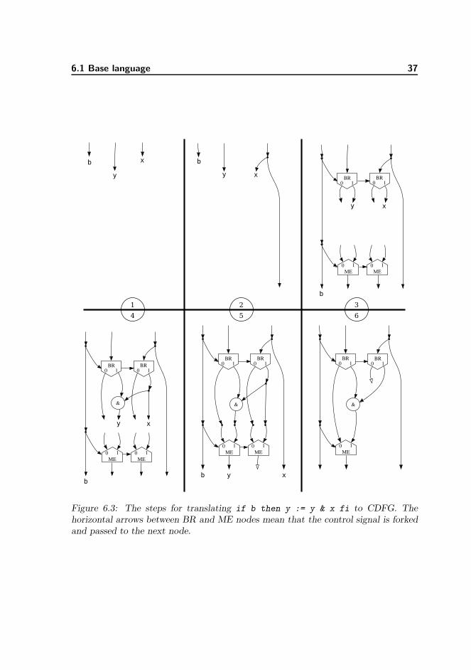
6.1 Base language 37
Figure 6.3: The steps for translating if b then y := y & x fi to CDFG. Thehorizontal arrows between BR and ME nodes mean that the control signal is forkedand passed to the next node.

38 Translation from Hurry to CDFG
Figure 6.4: Translation of a loop when three variables x, y, and z are in scope. Thisfigure is a redrawing of [Brage93, Figure 1-2].
computation begins. Without this, the loop could never start iterating because thetest is only executed after the initial tokens have passed through the Entry nodes. Inthe final iteration, the test will give 0, and this will cause the values being computedto escape the loop through the 0-output of the Exit nodes rather than passing throughthe body again. The control token will also reach the Entry nodes, so they will beleft with a 0-token on their control inputs just as they began.
In translation, we first create a pair of Entry/Exit nodes for each variable in scope.This introduces more nodes than needed, but dead code elimination removes theunneeded pairs later. A loop of the form do test then body od is translated to theform shown in figure 6.4. Being an expression, test can have no side effects, so thevariables pass through it as shown by the dotted lines.
As with conditionals, the edge map is updated so that variables which may be modi-fied in the loop are associated with the edges coming out of their Exit nodes, and therest are forked before entering the loop.
We are not finished, though. Haste has a generalised loop statement of the form
do t1 then b1
or t2 then b2
...
od

6.1 Base language 39
do x > 0 then
x := x - 1
or x < 0 then
x := x + 1
od
=⇒
Figure 6.5: Translation of a loop with two guards. This example is basically a veryinefficient way of writing x:= 0. The arithmetic nodes have been simplified to avoidcluttering the graph.
The loop executes the body of the first condition that evaluates to true. If all arefalse, the loop terminates.
Such a loop is translated by nesting the topmost test/body pairs inside the test ofthe lower ones. This is illustrated in figure 6.5, showing a loop with two tests usingone variable. When a token enters the outer loop, it will immediately flow into innerloop and test t1 first. Only if that fails will the data flow continue to test t2. If bothtests fail, the outer loop terminates. If any test succeeds, the data flow will againvisit t1 first after executing the correct body.

40 Translation from Hurry to CDFG
6.1.5 Statement composition
The sequence operator (S1; S2) is particularly easy to implement: we first translateS1 and then translate S2 in the resulting environment. This is because all necessarysequencing is already explicit by the flow of data and the I/O path.
The parallel operator (S1 || S2) requires a bit more work. We fork the variables usedin either S1 or S2, and the edge map used in translating S1 will use the Forks’ leftoutputs, and the map for S2 will use the right outputs. We must also fork the I/Opath and join it with a Sync node after translation of the two statements as explainedin section 5.3. At last, we merge the edge maps resulting from translating each side;for the variables not written to, we can take the edge from either side. Variableswritten to from exactly one side can be taken from that side. Unused edges arevoided as usual.
There is a problem if a variable is written to in both branches, or if it is read in oneand written in the other. Consider this code:
(x:=1 || x:=2); out ! x
It is not clear whether 1 or 2 will be the output. One could argue that since bothbehaviours are valid, we could just make the choice at compile time, which is equiva-lent to changing the || operator to ;. This is not good enough when we have channelcommunication, however. Consider the following code with external channels in andout:
x := 1; (in?x || out!x)
By sequencing his channel communication statements, an external actor controllingboth in and out should be able to dictate whether out is given 1 or whatever wasreceived on in, but this is only possible if the operations are truly parallel.
Because of this problem, we require that if a variable may be written to in one ofthe parallel branches, it may not be referenced in the other. A compiler error will begenerated for programs violating this. An alternative solution is explored in section7.6.
6.1.6 Arbitration keywords
Haste has arbitration keywords for variables, functions, and procedures for instructingthe compiler on whether arbitration is needed for controlling the access. These arepractical for situations where it might seem that arbitration would be needed, but theprogrammer can guarantee that it is not. Variables need arbitration only for writing,as parallel reading is always allowed. Arbitrated writing means parallel writing, whichwe disallow in CDFG as described in the previous section.
For functions and procedures we ignore arbitration flags, because upholding theminhibits parallelism. Consider the following example of a call to function f:
v := f(x); w := f(y)

6.2 I/O statements 41
The programmer guarantees that arbitration is not needed for f, because the secondcall does not begin until the first call is finished. In CDFG however, the two callswill share no flow and will therefore be implicitly parallel. If we wished to keep thenon-arbitration, we should impose an explicit ordering restriction. One of the aimsof the project is to uncover as much parallelism as possible for giving the schedulingalgorithm better conditions, so we have chosen to ignore all arbitration. If we were toreturn to Haste or realise the CDFG in hardware at a later time, we could use staticanalysis to determine which functions and procedures surely did not need arbitration,and put arbitration on the rest.
Haste also support arbitration flags for channels, but we also discard those. Internalchannels are implicit in CDFG and never declared, so an explicit declaration shouldbe added for supporting arbitration. For reasons of time constraints we have notimplemented that.
6.2 I/O statements
Our modelling of channel communication in a CDFG with Send and Recv nodeshas mandated the introduction of an I/O path as described in section 5.3. Duringtranslation, the I/O path is treated as a special variable, because it behaves like avariable in many ways. Like variables, it is present in the edge map whenever it maybe needed.
The I/O path is pulled through all loops via a pair of Entry/Exit nodes even if it is notused in the loop body. This ensures that tokens on the I/O path do not propagatebeyond the loop in case it never terminates, possibly allowing I/O that was notintended. This is unnecessary in many cases, but we leave it to later optimisationsto remove it.
6.2.1 Send statement
While the general send statement in Hurry can output to multiple channels, the Send
node in CDFG can only output to one channel, so we translate the send statementas if it were rewritten with temporary variables x1 through xn:
(c1, . . . , cn) ! expr =⇒(x1, . . . , xn):= expr ;
( c1 ! x1 || . . . || cn ! xn )
It is not at all obvious that this translation is correct. Introducing parallel compo-sition means that some of the sends can finish before all n channels are ready tocommunicate. The Haste manual says nothing about how communication on a tu-ple of channels is parallelised, so we designed an experiment that reveals what theHandshake Solutions compiler does. The code snippet:

42 Translation from Hurry to CDFG
<<a,b>> ! <<~,~>> || (a?~ ; b?~)
will deadlock if and only if sending on a tuple of channels must wait for all channelsin the tuple to be matched up with a receiver before sending on any of them. It didnot deadlock in our tests, so we assume that our rewrite of the send statement iscorrect.
After rewriting, each send statement uses only one channel and can be translateddirectly to a Send node. The edge carrying the value to be sent is connected to thedata input on this node, and the edge currently carrying the I/O path is connectedto its sync input. The edge map is then updated so the I/O path is associated withits sync output.
6.2.2 Receive statement
In our tests with the above snippet, we noticed that if we swap ? and !, it willdeadlock. This shows that the Handshake Solutions compiler does not parallelisereceive statements as it does send statements. We consider this behaviour to beinconsistent, and since the language manual says nothing about what is correct, weparallelise a receive on multiple channels as we did for the send.
The receive statement in Hurry is more complicated than the send statement due toa strange design choice of Haste: the received value can be sliced up and padded withor without sign extension in arbitrary places, but no other expressions can be appliedto it before storing it in a variable. We translate it to CDFG as if it were rewrittenwith temporary variables y1 through yn:
(c1, . . . cn) cast (t1, . . . , tk) ? (x1, . . . , xm) cast (T1, . . . , Tk)
⇓
( c1 ? y1 || . . . || cn ? yn ) ;
(x1, . . . , xm):= f(y1 :: . . . :: yn)
where the expression f contains the slices and pads that are equivalent to fitting eachti to Ti.
Each rewritten receive statement can now be modelled with a Recv node, whosesync input and output is connected like we did with the send statement. The Recvs’data outputs are concatenated and the assignment is translated like a normal Hurryassignment.
6.3 Subroutines
Both Haste and Hurry have a sharp distinction between functions and procedures.The body of a function can contain only an expression, and it can only be called from

6.3 Subroutines 43
an expression. The body of a procedure can contain only a statement, and it canonly be called from a statement.
A CDFG program is a list of CDFGs, each identified by a number, and each containingexactly one Param and one Return node. Each CDFG corresponds to a function ora procedure in the original Haste code, but the distinction between functions andprocedures is lost after translation to CDFG.
Unlike a CDFG, procedures in Haste and Hurry have no return value. Instead theycan have output parameters, which can be used for the same purpose; these aretranslated to having a return value in CDFG.
Figure 6.6 on the following page shows the signature of a procedure with every pa-rameter type included, and how a call to it is translated.
Because a CDFG only takes a single argument, the arguments are concatenatedbefore the call. Likewise, the return value is split up. Channel arguments cannot beexpressed as data flow, so the call node is annotated with those directly.
A fundamental difference between Haste/Hurry and CDFG is that CDFGs cannotbe nested like functions and procedures can be. A nested procedure can access thevariables in its scope just as in traditional high-level languages. This is equivalent toaugmenting the procedure’s parameter list with the variables and channels accessedfrom its scope, then passing those with every call. Figure 6.7 on page 45 shows anexample of how a nested procedure can be flattened. Our translation of proceduredeclarations performs similar flattening.
Finally, Haste has special rules for parameterless functions declared inside expres-sions. Because expressions have no side effects, the function will compute the samevalue in its entire scope, so it needs only be calculated once. We translate this bytreating the function declaration just like a variable assignment. In retrospect, itwould have been more general to handle this in a subsequent optimisation step thatinlines calls where all callers give the same argument.

44 Translation from Hurry to CDFG
P :proc( in ?var byte // input variable
& out !var byte // output variable
& inout :var byte // input/output variable
& c1 ?chan byte // input channel
& c2 !chan byte // output channel
).
...
will be called as
call P (c1, c2)
io path’
inoutinout
::
io path
in’out’inout’
slice 8slice 8@8
Figure 6.6: Example of how a call to a procedure using all supported parameter typesis translated.
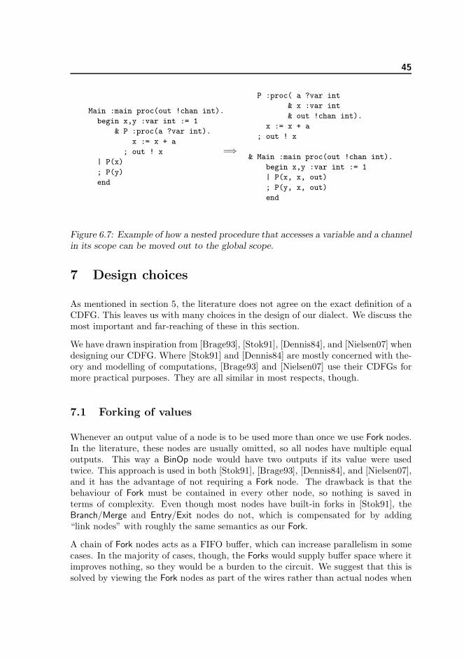
45
Main :main proc(out !chan int).
begin x,y :var int := 1
& P :proc(a ?var int).
x := x + a
; out ! x
| P(x)
; P(y)
end
=⇒
P :proc( a ?var int
& x :var int
& out !chan int).
x := x + a
; out ! x
& Main :main proc(out !chan int).
begin x,y :var int := 1
| P(x, x, out)
; P(y, x, out)
end
Figure 6.7: Example of how a nested procedure that accesses a variable and a channelin its scope can be moved out to the global scope.
7 Design choices
As mentioned in section 5, the literature does not agree on the exact definition of aCDFG. This leaves us with many choices in the design of our dialect. We discuss themost important and far-reaching of these in this section.
We have drawn inspiration from [Brage93], [Stok91], [Dennis84], and [Nielsen07] whendesigning our CDFG. Where [Stok91] and [Dennis84] are mostly concerned with the-ory and modelling of computations, [Brage93] and [Nielsen07] use their CDFGs formore practical purposes. They are all similar in most respects, though.
7.1 Forking of values
Whenever an output value of a node is to be used more than once we use Fork nodes.In the literature, these nodes are usually omitted, so all nodes have multiple equaloutputs. This way a BinOp node would have two outputs if its value were usedtwice. This approach is used in both [Stok91], [Brage93], [Dennis84], and [Nielsen07],and it has the advantage of not requiring a Fork node. The drawback is that thebehaviour of Fork must be contained in every other node, so nothing is saved interms of complexity. Even though most nodes have built-in forks in [Stok91], theBranch/Merge and Entry/Exit nodes do not, which is compensated for by adding“link nodes” with roughly the same semantics as our Fork.
A chain of Fork nodes acts as a FIFO buffer, which can increase parallelism in somecases. In the majority of cases, though, the Forks would supply buffer space where itimproves nothing, so they would be a burden to the circuit. We suggest that this issolved by viewing the Fork nodes as part of the wires rather than actual nodes when

46 Design choices
synthesising a CDFG into hardware. This retains the simplicity of our representationfor the high-level optimisation steps while still allowing later steps to have a moreconcrete view of the CDFG. It is only generally correct to remove buffer space inthat manner if the CDFG adheres to certain well-formedness criteria as section 8.1discuss.
7.2 Constants
Constants in [Stok91] fire exactly once at the beginning of the program. To use theirvalue more than once, they must therefore be carried into loops and conditionals likeregular variables. This would result in many more Entry/Exit and Branch/Merge pairsthan needed, which is not desirable in a practical implementation.
Constants in [Brage93] only fire when triggered by the I/O path, which makes dataflow follow control flow more strictly than necessary. [Brage93] concludes that itwould give better performance to trigger the constants locally.
We use the Const node from [Nielsen07], which has no inputs and fires as often aspossible. This ensures that its value is always available when needed.
An obvious concern is whether the constants might fire so often that it seriouslyincreases the power consumption of the circuit. This turns out not to be a problembecause the flow of tokens from a Const eventually reaches a node where it must waitfor some non-constant value. For example, in the translation of x + 1, the Const canonly fire once before it must wait for x. There may be a significant amount of wastedcomputation if the constant goes through a loop, but the overhead is still bounded andthus acceptable for a long-running program. The overhead is unbounded if a Const
node is connected directly or indirectly to Void, but such constructs are removed bydead code elimination.
7.3 Complexity of nodes
Most of the nodes in our CDFG are rather simple, which gives them a certain eleganceat the expense of larger CDFGs. We have already talked about how our Fork nodemakes the other nodes simpler. The slice node is also simpler than it could be, as itlacks support for multiple outputs; this made our translation of (x, y, z):= e requiretwo Fork nodes and three slice nodes rather than just one “multi-slice”.
Semantically simple nodes make it easier to automate analysis and optimisation ofthe CDFG in many cases. However, it also makes the CDFG look very different fromits Haste source code, making it very hard to translate the CDFG back to Hastecode in a form that looks anything like the original source. In particular, a do loopcan now only be recognised by finding all of its Entry/Exit nodes, then followingtheir edges to learn which nodes correspond to its test and body. The problem is

7.4 Representing channel communication 47
now that an optimisation may have drawn edges between the loop’s body and itssurroundings, making it impossible to define where exactly it ends. This could besolved by disallowing such optimisations, which is a rule we consider in section 8.1.
Translating loops and conditionals into many small nodes rather than one complexnode will potentially increase parallelism because they can operate independently ofeach other. This independence carries a cost in synthesised circuit area, so it is adisadvantage if it cannot be successfully exploited. In the case of loops, all Entry/Exit
components must wait for the same test, whose result is then copied out to all of theircontrol inputs. The independence can benefit parallelism here because Entry/Exit
pairs are allowed to lag behind the rest of the loop if they do not contribute to itstest, as long as there is sufficient buffer space to hold their control tokens. However,as with the Fork nodes treated above, we expect that this is seldom utilised, meaningthat the independence is a most often a disadvantage. We could therefore imaginethat a synthesis tool would try to deduce where each loop’s body and condition wereand synthesise as if the Entrys and Exits were synchronised.
Despite the potential problems, we have stuck with the small-node representation ofloops and conditionals traditionally found in the literature, hoping that the benefitof simplicity would outweigh their disadvantages.
7.4 Representing channel communication
Translation of Haste code requires some way of representing channel communication.In the previous works on CDFGs we could find, the closest thing to channel commu-nication is [Brage93], who has a node for sampling the level of a wire and for writinga value to an output latch, enabling data exchange with the external environment.Our Send and Recv nodes behave like these, except that they wait for the other partyto handshake before they can fire.
Our representation of channel communication is a layer of semantic rules “above”the data flow defined by the CDFG’s edges. By this we mean that due to channelcommunication it is not possible to follow the data flow in a CDFG simply by followingthe edges. We would have liked to model channel communication with edges only,but there are a number of problems with that approach:
• Channels for exchanging data with the external environment still need to bemodelled somehow. This means that we must have Send and Recv nodes, so ourdata structure would not become simpler even if we could do internal channelcommunication over edges with the nodes we have currently.
• A naıve translation of internal channel communication would be to just drawa data edge from the sender to the receiver along with synchronising their I/Opaths. This turns out to be inadequate because Haste allows multiple sendersand multiple receivers on the same channel in parallel. It will not be determined

48 Design choices
until run-time which pair of sender and receiver will exchange data, so we wouldneed special components to perform this arbitration.
• If we draw edges from senders to receivers, there is no restriction on where theymay go. They could run from the body of one loop into the body of another,or they could run from the left branch of a conditional into the right one. Onemay see this as an advantage of the CDFG representation over traditional tree-like representations, but we see in section 8.1 that it becomes very hard to dooptimisations if we have no restrictions on where edges may go.
• It would become more complicated to pass around channels as procedure pa-rameters, and we would have to put all procedures in the same CDFG to enableinter-procedural channel communication.
Having decided against channel communication over edges, we also needed to decideupon the role of the I/O path. Our nodes for channel communication (Recv, Send,Sync) and procedure calls (Call, Param, Return) give special treatment to the I/O pathand keep it completely isolated from the data edges just as it is done in [Brage93].This is not truly necessary; one could create an I/O path from a data edge by slicingit to a width of 0 bits, or one could synchronise an I/O path with a data edge byconcatenating them with the BinOp node for concatenation. Such techniques couldremove the special I/O path output edges from Recv and Param as well as the specialI/O path input edges in Send and Return.
The Sync node would be entirely redundant because it is a special case of concatena-tion, since concatenation of two 0-bit edges produce a 0-bit result after waiting for atoken on them both. The Stop node is redundant as well, or at least it does not needan input edge because discarding input can be done by Void just as well.
Despite the simplifications we could get by mixing the I/O path with data, we optedto keep them isolated by convention, although our data structures do not preventmixing them. This choice comes from a desire to be able to recognise the I/O pathin optimisations coming after translation to CDFG. At the same time, we wanted toleave open the possibility of mixing them in case we changed our mind later. Section8.1 points out other potential problems with mixing I/O path and data edges. Section8.2.4 describes an optimisation we have implemented as a proof of concept that mixingthe I/O path with data can be advantageous.
7.5 Representing procedures
Procedure calls in our CDFG dialect is modelled in roughly the same manner as in[Stok91]: each procedure has its own CDFG, and calls are modelled in a semanticlayer independent of the data flow defined by edges. This adds more complexityto our CDFG dialect, which we generally want to avoid. This section will explorealternative implementations of procedure calls.

7.5 Representing procedures 49
Procedure calls are not possible in [Brage93] or in the static data flow graphs of[Dennis84]. They are also absent from the Balsa language, and [Bardsley98] seems toindicate that they were not originally present in Tangram, the predecessor of Haste.Instead of real procedure calls, they have defined procedures, which are conceptuallyequivalent to macros in C. At each “call” they are simply copied at compile time,and their arguments are substituted for their parameters. This language feature isalso present in Haste; although useful for many purposes, it is not interesting for thisdiscussion because it is invisible after translation to Hurry.
The purpose of procedure calls is to access a shared resource from more than one placeso it does not have to be copied on the circuit. An alternative to procedure calls –and the only option in Balsa – is to use channel communication. The equivalent ofa procedure would then be a process that runs in an infinite loop, taking input fromone channel and placing output on another after doing some computation. This isthe behaviour of our running example of the factorial function that we first saw onpage 7.
If the users of the procedure can guarantee that they will never use it in parallel, thenthis works. Otherwise there must be some way of arbitrating between contendingusers. This could be modelled by letting each user send an id value along with thedata for his call. When it is time to return the result, the id value will decide onthe channel to return the value to, thus choosing the correct recipient. The sharedprocedure would then look like:
forever do
in ? <<id,parameter>>
; result := ... // perform some computation on parameter
; case id
is 0 then caller0 ! result
or 1 then caller1 ! result
...
si
od
It gets more complicated though, because Haste procedures can take channels asarguments besides data. This creates a temporary run-time aliasing of those channelsfor the duration of the procedure call. To emulate this behaviour in the channel-callmodel, the caller would have to send channel parameters along as arguments in thesame manner as the id value. Because channel parameters may be referenced multipletimes during the call, as opposed to a return value, this could create a large numberof case statements. This can be worked around by creating yet another process foreach aliased channel whose only purpose is to send a value to the right place, givena value and an id.
The reason why we did not implement procedure calls as channels is that it may ruinperformance. Channel aliasing in Haste is most likely implemented very efficiently by

50 Design choices
flipping a simple switch on the circuit to re-route the wires during the call. Replacingthis with case statements could destroy the very performance that we are aiming tooptimise.
7.6 Representing parallel read/write
As described in section 6.1.5, our compiler will exit with an error if it sees a write to avariable that may occur in parallel with a read or a write to the same variable. Usingan idea similar to the one we saw for procedure calls above, this could have beenemulated with channel communication to a process running in parallel with the mainprogram. This process first reads a command from a control channel, then eithersends or receives the variable over a data channel, depending on the command.
Figure 7.1 on the facing page shows an example of how this could be implemented. Itworks because the users of x follow the protocol of only communicating over x_dataafter having successfully communicated over x_ctl. This allows us to declare x_dataas not using arbitration for send (narb!) or receive (narb?), while x_ctl must arbi-trate between contending senders (arb!).
The code should convey the impression that this would not be an efficient solution.It is therefore more interesting conceptually than practically, so our compiler doesnot implement it.

7.6 Representing parallel read/write 51
begin x_ctl :chan [0..1] arb!
& x_data :chan int narb! narb? narrow
|
// Process running in parallel with main program
begin x :var int
& command :var [0..1]
| forever do
x_ctl ? command
; case command
is 0 then x_data ! x
or 1 then x_data ? x
si
od
end
||
... the rest of the program goes here ...
// Transformation of: (x := 2 || x := 3) ; out ! x
(
(x_ctl!1; x_data!2) || (x_ctl!1; x_data!3)
; begin tmp :var int
| (x_ctl!0; x_data?tmp)
; out ! tmp
end
)
...
end
Figure 7.1: A transformation of the statement (x := 2 || x := 3) ; out ! x
that makes it acceptable for our compiler.

52 Transformations on the CDFG
8 Transformations on the CDFG
When the Haste code has been successfully translated into a CDFG it is obvious toask whether we can apply optimising transformations on it. We have many traditionaloptimisations, such as dead code elimination and common subexpression elimination[Dragon]. On top of this, we might be able to utilise the CDFG representation,and come up with optimisations that would be hard to do with conventional coderepresentation.
In both [Stok91] and [Brage93] several of the classical optimisations from [Dragon]are suggested, though only informally described. It turns out that it is dangerous touse these informal descriptions as basis for implementations as the complexity of theCDFG behaviour makes it hard to predict when a transformation is correct. Thisproblem can be partially solved by restricting the CDFGs to adhere to some well-formedness requirement. In section 8.1 we give an example of why such a restrictioncould be helpful, what it could look like, and which issues must be addressed in futurework before it could be safely applied.
In the section that follows it, we describe a series of small optimisations that wehave implemented. These optimisations assume that the CDFGs given abide to thewell-formedness described in section 8.1. We have not proven the optimisations tobe correct, but with informal arguments and testing, we are fairly certain that theyare. Thus, they are solely a practical addition to our compiler.
8.1 Well-formedness
When our translation is done, the resulting CDFG has certain nice properties; e.g. apath leaving a loop must always go through an Exit node. A potential strength of theCDFG formalism, however, is that CDFGs can break those properties and still havewell-defined behaviour. An example of this is the right CDFG in figure 8.1 on the nextpage where a Const 0 node outputs the I/O path. We could imagine optimisationsthat transformed our original CDFG obeying the properties into one that did not,thus making it necessary for later optimisations to cope with non-restricted CDFGs.
However, having such a liberal view on valid CDFGs makes it hard to predict theconsequences of even simple transformations. A clear example of this is the removalof nop nodes. We insert nop nodes during conversion and during certain optimisationsbecause it is an easy way to tie edges together. As they just forward all values givenon the input, removing them after compilation should be easy.
A problem with nop-removal is evident on the right CDFG in figure 8.1. Whencompiling the Haste program snippet with our compiler, the result is the CDFG inthe middle. By following the flow of tokens systematically, one can see that the CDFGon the right has the same behaviour, and therefore one could imagine optimisationsthat transformed the middle CDFG into this.

8.1 Well-formedness 53
forever do
a?~ ;
b?~
od
=⇒⋆=⇒
⋆
⋆
0
recv(a)
recv(b)
Figure 8.1: An example of a Haste program snippet that can be translated to themiddle CDFG and magically optimised into the left CDFG where we cannot add anop without changing the behaviour.
The problem is that adding a nop node in between the two Recv nodes in the CDFGon the right changes the behaviour of the program: without the nop, the CDFG isforced to interleave the communications on the channels, as there can be only onetoken on an edge at a time. Having a nop node on the edge between the Recvs wouldmake it act like a one-place FIFO buffer, making it able to receive twice on a beforehaving to send the first time on b. When adding a nop can change the behaviour, wecannot in the general case remove nops without changing the behaviour.
The nop removal is such a simple and seemingly correct transformation that if weneed advanced analyses to determine where it can be applied safely, the more complextransformations seem well out of reach. A nop only provides a buffer on the edgesit connects, so all optimisations removing nodes or re-routing edges always have totake some measure of buffer sizes into account, if nops cannot be safely removed.An example of this is when we view the Fork nodes as just wiring instead of actualnodes when synthesising, as described in section 7.1. If we cannot in the general caseremove nops, we cannot do this simplification.
There is a natural objection to the example however: The I/O path is initiated froma node other than a Param node, which is outside its intended use. This, in turn,implies that we have a concept of well-formedness of the I/O path which we adhereto. In the CDFGs we produce from the translation, the I/O path has a list of niceproperties, like being initiated in Param nodes. If we were to specify these properties

54 Transformations on the CDFG
1
0 1EN
0
EX0 1
+
(nop)
Figure 8.2: When the nop is present on the edge going out of the loop, the add nodewill fire once, but if the nop is omitted, the add will never fire.
and require all CDFGs to obey them in order to be well-formed, we might be able tosave the intuition that the removal of nop nodes is legal on well-formed CDFGs.
Unfortunately, it is not enough to require well-formedness on the I/O path alone forsuch a guarantee. In the example in figure 8.2, there is no I/O path, but the presenceof a nop node still changes the behaviour. The loop will iterate twice, the first timewith the value 1 and the second with 0. If the edge leaving the loop from inside thebody had no nop, then after the first iteration the edge would have a token waitingfor the add node to fire. Therefore, when the token in the next iteration reached theFork node, it would not be able to fire, deadlocking the loop. If there was a nop,however, the Fork node could fire the second time, and in turn letting both the Exit
node and add node fire once.
This example breaks an intuitive requirement that has nothing to do with the I/Opath: edges may not begin inside a loop and end outside it. It also leaves a tokenstranded on the left input of the add node, which disallows re-entrance of the CDFG.
This example relies on nodes whose semantics are quite standard in the literature,and it even works with the constant nodes of [Brage93], which only fires when it

8.1 Well-formedness 55
receives a token from the I/O path.
It seems then, that this is not simply a problem that we have because of channelcommunication or rash node definitions, but something that any definition of CDFGsemantics should consider. Neither [Brage93] nor [Stok91] do that, but from theirtranslation algorithm and from the loose descriptions of suggested optimisations, itseems that they silently assume the CDFGs to obey certain rules of well-formedness:
• An edge may not begin inside a loop’s body and end outside it.
• An edge may not begin inside a loop’s condition and end outside it.
• An edge may not cross between different branches of a branching.
• An edge may not begin inside a branching and end outside it.
• The I/O path may only be initiated by a Param node and only be terminatedby a Return node
• If the I/O path has been forked, it may only be merged by a Sync node.
To back up this list, we have constructed a number of unorthodox CDFGs wherenop nodes cannot be removed safely. These are shown along with a short descriptionin appendix A. They are written in our own CDFG dialect, but only relying onbehaviour readily expressed in the dialects of [Brage93, Stok91, Dennis84].
There are obvious questions that need to be answered before these requirements canbe used, e.g. “what is the inside and outside of a loop’s body?”, “what defines aloop and can two loops with different conditions be intertwined?”, “what exactlydefines the I/O path”, etc. The answer is in most particular cases intuitive, but toanswer them in general we need a precise formal definition of the well-formednessrequirements.
Having formal requirements that the CDFGs should adhere to, we would like to provethat the transformations we come up with are correct. To do this, we would needa formalisation of the CDFG semantics, a formal definition of semantic equivalencebetween two CDFGs, and a framework in which we can prove these equivalencesunder a transformation. Formalising the semantics has been done several times;in [Brage93, Stok91, Kavi86, Bojsen93] different formal semantics are specified buttheir aims are all different from ours, so it is unclear if any of their solutions wouldbe expedient for our purposes. In particular [Bojsen93] shows correctness of a CDFGwith regard to a high-level specification, but the problem of specifying semanticequivalence between CDFGs without such prior specifications is not dealt with. Thus,this is a very interesting field of future work that should be examined properly.
It should be noted that without well-formedness we might still be able to come upwith optimisations that could be proven correct. However, it seems that it is then

56 Transformations on the CDFG
hard to find advanced optimisations that are correct, and proving them might beeven harder.
The CDFGs produced by our compiler adhere to all the well-formedness rules above.The Stop node was actually introduced instead of using Void nodes so the fifth rulewould be obeyed when translating a stop statement. Channel communication canemulate the transfer of data done by edges, and could thus emulate edges that wouldviolate the first four requirements. This appears not to be a problem, though, as longas the I/O path obeys the last two requirements.
Returning to the removal of nop nodes, we have not been able to construct a CDFGadhering to the list of well-formedness requirements where it cannot be safely applied.This is of course far from a proof of correctness, but combined with a number of loosearguments, we are rather certain that it is a safe transformation on the well-formedCDFGs our compiler produces.
8.2 Implemented optimisations
After this discussion on the need for well-formedness, we now describe some optimisa-tions that we have implemented. They assume that the input program only consistsof well-formed CDFGs according to the requirements listed in section 8.1, and ex-cept for Channel merging, they all return well-formed CDFGs. Channel mergingis included for proof of concept that useful optimisations violating well-formednessexists.
We do not have proofs for the correctness of these, but are rather confident thatthey are safe under the well-formedness restrictions, based on informal argumentsand on testing we have done. These optimisations should therefore not be seen as acontribution to theory, but rather to the practicality of our compiler.
8.2.1 RemoveNop
We have not been able to construct a CDFG that adhered to the well-formednessrequirements in section 8.1 and where nops could not be safely removed. As Hasteuses explicit variables or channels for buffering values, we are fairly certain that thecompilation from Haste to CDFG will never introduce CDFGs that depend on nodesfor buffering, and therefore not on nops. We have therefore implemented RemoveNop.Several of the other optimisation do not remove nodes themselves, but translate themto nop nodes and let them be removed by RemoveNop.

8.2 Implemented optimisations 57
8.2.2 Dead code elimination
Dead code elimination is the classic transformation of removing code that certainlydoes not affect the result and side effects of the computation [Dragon]. In CDFG itamounts to removing unnecessary nodes. Under the restriction of well-formedness,dead code elimination becomes exceedingly simple to implement.
Nodes only affect the computation of nodes that depend on them, except for channelcommunication nodes. The only side effects of running a CDFG is the channel com-munication and the possible value returned by the Return node. Therefore, nodesthat are not a predecessor of a channel communication or the Return node can neveraffect any observable behaviour and can be removed. As well-formedness requiresthat the I/O path is only terminated by the Return node, all channel communicationnodes are predecessors of the Return node. Thus, we need only begin from the Return
node and traverse backwards via the edges, marking all nodes in the process. Allunmarked nodes must be dead and can be removed.
8.2.3 MapStructure
When performing transformations on graphs, it is a recurring task to find some setof nodes connected in a certain way and replacing it with another set of nodes. Forthis purpose, we have implemented MapStructure, which provide a flexible way ofspecifying which structure to be matched upon and what transformation that shouldbe performed. With it, we have implemented three optimisations:
VoidForks finds all occurrences of a Fork where one of the outputs ends in a Void;this can be simplified by removing these two nodes. To ease the actual imple-mentation they are instead replaced by a nop, which is itself removed later.
SimplifySlice finds occurrences of a chain of slice or nop nodes with at least oneslice; they can be simplified to just one slice.
RemoveTrivialSlice finds occurrences of slice nodes that has the same input andoutput type; they can just be removed. As with VoidForks they are reduced tonops which are removed later.
When called, MapStructure will replace every occurrence of some structure in asingle CDFG with new nodes. The pattern language used to specify what structureMapStructure should match upon is quite powerful and supports matching arbitrarynodes, logical and and or matching on sub-structures, and recursive matching onstructures. Though general, it has keywords and flags for securing good performance,and the three optimisations above have the same asymptotic running-time as if theyhad been implemented by hand.

58 Transformations on the CDFG
recv(4)
data r io out
send(4)
s io out
data s io inr io in
=⇒
::
slice:0 data
s io out r io out
data
s io in r io in
Figure 8.3: Channel communication that can be merge. It requires that there are noother Sends or Recvs on channel 4.
Though these optimisations are simple, MapStructure supports matching on complexstructures, and should make it much easier to implement later optimisations. Seeappendix B for further details on this language and how to specify SimplifySlice andVoidForks in it.
8.2.4 Channel merging
To demonstrate that useful optimisations that break the well-formedness require-ments exist, we have implemented the channel merging optimisation. We are confi-dent that requiring well-formedness is the most advantageous approach to optimisa-tions, so channel merging is included for proof of concept and not due to a change ofheart.
The optimisation finds instances of channels that are not parameters in a CDFG,that are never aliased in calls, and where there is only one Send and Recv and theyare in the same CDFG. Then the transfer of data is always deterministic and can beexchanged with edges. It can be transformed as shown on figure 8.3. We must makesure that tokens on the two incoming I/O paths and the incoming data path are all

8.2 Implemented optimisations 59
present before we output on any of the outgoing edges, because this is the behaviourof the Send/Recv. This is ensured by first synchronising the I/O paths with a Sync,and then synchronising the result with the incoming data path. This clearly violatesthe well-formedness requirement that an I/O path may only terminate in a Return
node, but its behaviour is still well-defined. We then create a new I/O path from theresult by forking it and slicing it to 0 bits.
Apart from breaking well-formedness when concatenating data with the I/O path,the channel merging can introduce edges that exit bodies and conditions of loopsand bodies of branches. In the general case, then, channel merging breaks all well-formedness requirements but the last.
We are reasonably confident that this optimisation is correct if the incoming CDFGis well-formed. It will, however, output a non-well-formed CDFG, and we thereforeapply it as the next to last optimisation. The last is ClearCDFG described in thenext section, which will not be affected by it.
8.2.5 ClearCDFG
Simply because it was very easy to implement and convenient for several of our tests,we have implement ClearCDFG that removes CDFGs that will never be called. Webegin from the main CDFG and simply marking all CDFGs that may be called fromthat, marking CDFGs maybe called from them, etc. Unmarked CDFGs can never becalled and are removed.
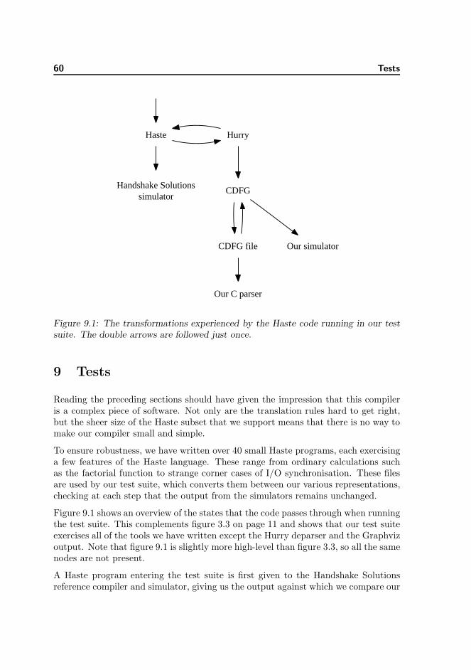
60 Tests
Haste Hurry
Handshake Solutionssimulator
CDFG
CDFG file Our simulator
Our C parser
Figure 9.1: The transformations experienced by the Haste code running in our testsuite. The double arrows are followed just once.
9 Tests
Reading the preceding sections should have given the impression that this compileris a complex piece of software. Not only are the translation rules hard to get right,but the sheer size of the Haste subset that we support means that there is no way tomake our compiler small and simple.
To ensure robustness, we have written over 40 small Haste programs, each exercisinga few features of the Haste language. These range from ordinary calculations suchas the factorial function to strange corner cases of I/O synchronisation. These filesare used by our test suite, which converts them between our various representations,checking at each step that the output from the simulators remains unchanged.
Figure 9.1 shows an overview of the states that the code passes through when runningthe test suite. This complements figure 3.3 on page 11 and shows that our test suiteexercises all of the tools we have written except the Hurry deparser and the Graphvizoutput. Note that figure 9.1 is slightly more high-level than figure 3.3, so all the samenodes are not present.
A Haste program entering the test suite is first given to the Handshake Solutionsreference compiler and simulator, giving us the output against which we compare our

61
$ time ./test
t/arithmetic_types.ht ... OK
t/arithmetic_types.ht (through Hurry) ... OK
t/assign.ht ... OK
t/assign.ht (through Hurry) ... OK
[cut 72 lines]
t/tupleIO.ht ... OK
t/tupleIO.ht (through Hurry) ... OK
t/wrapper.ht ... OK
t/wrapper.ht (through Hurry) ... OK
All tests OK
./test 0.85s user 0.41s system 82% cpu 1.515 total
Figure 9.2: The output of running our test suite. The timing statistics at the bottomshow that it takes 1.5 seconds to run all 40 tests on a Pentium M 1.86 GHz laptop.This does not include the time spent in the Handshake Solutions compiler.
own tools. The Haste code will then be translated to Hurry. We can translate backand forth between Haste and Hurry any number of times, and the code resultingfrom these translations can be subjected to the entire test suite again. Our test suitedoes this just once. The Hurry code will be compiled to CDFG, then deparsed to afile. This file is fed to our C parser to check that it is not rejected. It is also readback into our CDFG simulator, and the test suite verifies that it produces the sameoutput as the Handshake Solutions simulator.
Figure 9.2 shows what it looks like to invoke the test suite. Each file is simulatedfour times in total: with both the Handshake Solutions simulator and our own, andboth directly from the Haste source and after being translated back from Hurry.
The test suite employs a few tricks for practical reasons. Because the HandshakeSolutions tools are commercial, we cannot install them on our own machines. Wetherefore invoke them remotely by copying the Haste files over the network andrunning the tools on the machines on which they are installed. Because the HandshakeSolutions tools spend several seconds on each file, we maintain a cache of their output,as it should not change when given a file with the same contents. This speeds up atypical test run by an order of magnitude.

62 Tests
9.1 Larger programs
We were fortunate enough to obtain copies of two programs that were written bystudents attending DTU course 02204 “Design of Asynchronous Circuits”. The firstis a division algorithm using the Newton-Raphson method, and the second is a “Mini-MIPS” processor as introduced in the DTU course 02151. This gave us an opportunityto test our tools on larger programs than our unit tests.
The division program only used the subset of Haste supported by our compiler, so itcould be compiled and simulated with no changes except for the correction of a smallsyntax error that was tolerated by the Handshake Solutions compiler.
The MIPS uses arrays for storing its program, data memory, and registers, so wehad to modify it heavily to make our compiler accept it. We tried emulating arraysin two ways, both of them applying some semi-manual transformation on the sourcecode before compiling. The first approach is to store the array as one huge variableholding all of its contents. The second is to have many small variables, each holdingone array element. In both approaches there are large auto-generated case statementsto translate index numbers to data.
To test the MIPS, we output the addresses and values for each write to registers ordata memory. In the approach where the memory is one huge variable, our simulatoroutputs the same numbers as the Handshake Solutions simulator. In the approachwith many small variables there appears to be a bug in our compiler or simulator, assome of the numbers are different. We have not had time to investigate this further,and we fear that such a bug may be hard to isolate due to the size of the MIPSprogram.
9.2 CDFG simulator
Our CDFG simulator starts by performing some consistency checks to be reasonablyconfident that the CDFG is a valid instance of the data structure described in section5.4. This is primarily a check that each edge connects exactly two nodes along witha type check of each node’s outputs compared to its inputs.
The CDFG simulator works by maintaining a map of Edges → Z ∪ {empty} to keeptrack of the token on each edge. It also maintains a work-list containing all nodesthat may fire at any given time. For performance this list should be small, but forcorrectness it must be a valid over-approximation. Nodes are added to that list whentokens are placed on their inputs or removed from their outputs. In the main loopof the simulator, each node on the work-list is checked to see if it can fire, whichis determined in a node-specific way. Regardless of whether it fires, it is removedfrom the list. If the work-list becomes empty at some point, the program must bedead-locked, and simulation ends.

9.2 CDFG simulator 63
Because the program is not guaranteed to terminate, we have to apply some principleof fairness to the simulation. Consider a program that contains an infinite loop:forever do skip od || out ! 1
Some node in the infinite loop will always be ready to fire, so it would be seman-tically correct to never fire the Send node. It would not be a realistic simulation,though, because if this program were compiled into a circuit it would surely output1 immediately. Our work-list implementation resembles a FIFO, ensuring that nodesare never starved in this manner.
The simulator is further complicated by the support for channel communication andprocedure calls. Channels are supported by maintaining queues of the nodes thatmay be ready to send or receive on each channel. For procedure calls, we maintain amap of Channels → Channels used to resolve the channel aliases that are created atrun-time when a CDFG is called with channel parameters. We must also rememberwhich node called a given CDFG in order to send the return value back to the rightplace, and we must maintain a queue of nodes that are pending to call a given CDFGafter it returns its current call.

64 Future work
10 Future work
The project has ended with a working compiler with good performance, but thereare many areas, practical as well as theoretical, that would be interesting to explorefurther.
Seen from the perspective of a professional Haste programmer, it is imperative thatthe compiler supports arrays of the types in Haste. A quick-fix solution like the onewe mentioned in 9.1 would yield terrible performance if it were to be synthesised, andis not realistic. A possible solution is described in [Stok91], though it is uncertain ifthe addition of procedure calls and internal channel communication imposes problemson that solution.
The compiler is thought of as a front end for an optimising synthesis tool, and aswith all optimising compilers, it is not expected that it will perform better thanhand-optimised code compiled syntax-directedly. As the transformation to CDFGremoves much optimisation done by the programmer, it would be an advantage for aprogrammer to be able to use compiler directives to toggle when to compile syntax-directedly and when to optimise. This could most easily be done if the back end ofcompiler were to output in optimised Haste code. We could then collect the untouchedand the optimised Haste code in one, and compile it syntax-directedly by HandshakeSolutions’ compiler in the end.
It is, as we have seen in section 8.1, very easy to overlook unwanted behaviour in agiven CDFG. It is therefore important that the translation we perform from Hurryto CDFG is proven to be correct with regards to semantics. This, of course, requiresformal semantics for both Hurry and CDFG and a framework in which to performsemantic equivalence. In [Bojsen93], a framework for proving correctness of a CDFGwith regard to a behavioural specification is set up, and it might be possible to utilisethe methods described there. This would require the translation of Hurry into thelogic that is used as the specification language, which might be as difficult to provecorrect as the translation from Hurry to CDFG, however.
There is much potential in performing optimisations on the CDFG, but doing thiswould probably require that we limit ourselves to some notion of well-formed CDFGs.To find a well-formedness definition, it should first be examined what properties wewish our well-formed CDFGs to abide, just as we sought to make nop-removal legalin 8.1. We should then find a set of requirements, formalise them, and then provethat under those requirements CDFGs do indeed abide to the properties.
With a formalisation in hand, we can think of many optimisations that could be in-teresting to prove correct and implement afterwards: Common sub-expression elim-ination, invariant code motion, loop unrolling, inlining, etc [Dragon]. To prove anoptimisation correct, however, we would need the formalisation of the CDFG seman-tics and a notion of semantic equivalence. These can be expressed in a multitude ofways, many of which might prove to be unhandy when trying to perform correctness

65
proofs, so it should be done with care. On this field, we have a promising approachthat we would have liked to examine further, but because of time constraints, wehave not come to any concrete results.
When working under a well-formedness restriction, it would be convenient if the datastructure representing the CDFG guaranteed well-formedness was upheld; e.g. byencapsulating the bodies and conditionals of loops. This might simplify optimisationsand analyses considerably. If it were reflected in a formalisation of the CDFG, it mightalso simplify the proofs performed with it.
As an ending note, the CDFG representation might not only be an advantage withhardware languages, but also for software. As computers are becoming increasinglyparallel, extracting parallelism from a sequential program becomes an attractive wayto increase performance.

66 Conclusion
11 Conclusion
The main result of this project is a working compiler from a subset of Haste to aCDFG. The compiler is envisioned to be used as a first step in an optimising synthesistool for Haste.
To perform this task we first designed an intermediate language Hurry that simplifiesHaste to a great extent, but without losing descriptive power or introducing ineffi-ciencies. Using an intermediate language as a stepping stone in a compiler is standardpractice, and it simplified the actual translation to CDFG immensely.
None of the dialects of CDFG described in the literature directly supports the Hastefeatures of CSP-like parallel processes and channel communication. We thereforedesigned our own CDFG dialect, which was based upon [Brage93], but with significantalterations and extensions. We have compared our dialect with prominent dialectsfrom the literature, and generally remain satisfied with our design. The approachand actual translation from Hurry to CDFG was described in detail.
To test the correctness of the compiler, we have implemented a simulator for ourCDFG dialect, which also means that we have a simulator for our source languageHaste. We have implemented a testing framework that revolves around comparingsimulation results with the simulator from Handshake Solutions, which stresses everypart of our compiler.
We have examined the possibility of optimising the resulting CDFG using the classicalcompiler optimisations. Our results show that without a well-formedness requirementon its structure, it is difficult to safely perform even simple optimisations. With thestarting point being the intuition that the nop node, CDFG’s counterpart of the skipstatement, can be safely removed from any well-formed CDFG, we propose a list ofwell-formedness requirements. There is still a long way to go, as this list should beformalised and the starting point shown to actually hold under the requirements.However, it is an important problem that we have not seen discussed elsewhere inthe literature and has great perspective for future work.
The compiler is accompanied by a number of tools for translating between variousrepresentations. There are programs for executing the simulator, a parser and adeparser for a format describing the CDFG, another parser for this written in C, anda deparser for producing Graphviz files to visualise the CDFG.
As a conclusive remark, we believe that our compiler and associated tools can behelpful in advancing the state of asynchronous hardware synthesis.

67
A Malformed CDFGs
In section 8.1 we introduced a list of well-formedness requirements for CDFG. Thislist was based upon a number of unorthodox CDFGs that we have constructed suchthat the presence of a nop node change their behaviour. In this section we presentand shortly describe those CDFGs.
It should be noted that no Haste code could be compiled with our compiler and resultin these CDFGs, as our compiler only produces CDFGs that are well-formed underthe restrictions in section 8.1. However, they have all been written manually in theCDFG language that we can parse, and have been tested with the CDFG simulatorto have the specified behaviour.
An edge may not begin inside a loop’s body and end outside it
The CDFG is shown in figure A.1 on the next page. The loop will iterate twice,each time decrementing the number that runs through. With the nop present,the path from the Fork after the Exit to the add node can hold two tokens, andeach of the two first iterations will put one there. Then the condition will runa third time, yielding a 0 which causes a token on the left output of the Exit.Then the add node can fire once, letting a token leave the CDFG.
Without the nop node, the second iteration will have a token stuck on the edgeafter the Exit and before the Fork node, because the token on the edge beforethe add node will disallow it to fire. The CDFG will deadlock there and notoken will ever leave the add node.
An edge may not begin inside a loop’s condition and end outside it
An example of this was shown in figure 8.2 on page 54.
An edge may not cross between different branches of a branching
The CDFG is shown in figure A.2 on page 69. The principle is that theBranch/Merge pair will only let tokens through once it has got a token oneach branch because of the add node. The right Entry/Exit pair make it possi-ble to get this. The loop will iterate twice, and in both iterations a token willbe input on the Branch. In the first iteration, the condition will be 1 and in thesecond it will be 0. The first token will be stuck in between the Branch/Merge
pair, so the left Entry/Exit pair will not begin its second iteration. The rightone will, though, as its input is independent from the Branch/Merge, and thiswill cause a second token to pass down to the Branch.
Now, if the nop is present, the control edge for the Merge will have room for thesecond token, meaning that the Fork just before can fire. This in turn makesthe Branch fire, giving the add node the second token. Then the Merge willfire twice, letting the left Entry/Exit pair perform its two iterations, and in theend, a token will escape on the left output of the left Exit. Had the nop not

68 Malformed CDFGs
2
0 1EN
0
<
-
EX0 1
+
(nop)
1
Figure A.1: An edge may not begin inside a loop’s body and end outside it.

69
Figure A.2: An edge may not cross between different branches of a branching.

70 Malformed CDFGs
BR0 1
(nop)
0 1ME
+
Figure A.3: An edge may not begin inside a branching and end outside it.
been there, the Fork before the control edges of the Branch and Merge wouldnot have had room to fire, deadlocking the CDFG.
An edge may not begin inside a branching and end outside it
Because of the complexity of this example, we have extracted the essentialpart of it, shown in figure A.3. The surrounding looping construction that isnecessary for the example to work is shown on figure A.4 on the next page, andresembles that of the last example. That will not be described in further detail.
The surrounding construction makes sure that the branching will get threetokens with value 0, 0 and 1 before having to output anything. If the nop ispresent, the branching will then output a single token with value 1, and if it isomitted, it will deadlock.
The first token will go through the left branch and get stuck just before theadd node. The second token will also go through the left branch, but becauseof the first token, the Merge cannot fire. Therefore, a token will be stuck onits control edge. The third token will reach the Branch and the Fork beforeits control. Now, if the nop is omitted, the token from the second iterationwill disallow the Fork to fire, hence preventing the Branch from ever receiving a

71
Figure A.4: An edge may not begin inside a branching and end outside it.

72 Malformed CDFGs
token on the control edge, deadlocking the CDFG. Had the nop been there, onthe other hand, the Fork could fire, letting the Branch fire in turn. This wouldoutput a token on the right edge, which would give the add node its secondinput. This would cause it to fire, causing it to output a token.
The I/O path may only be initiated by a Param node and only be termi-nated by a Return node
In the CDFG in figure A.5 on the facing page, the channels a and b are exter-nal channels, and the I/O path has been voided after the Recv on channel b.The CDFG will loop forever and receive on the channels. The CDFG mightin the first iteration receive on channel a and not on b, leaving a token on theinput edge to b’s Recv. The loop will continue to next iteration, and if thenop is omitted, the Fork in the body cannot fire because of the stranded token,freezing the CDFG until the external actor sends on b. If, however, the nop
was there, the Fork could fire, making the Recv on a capable of firing. This isdifferent externally visible behaviour, as explained in section 5.3.
This requirement is why we have Stop node instead of terminating the I/O pathwith a Void node when translating a stop statement.
If the I/O path has been forked, it may only be merged by a Sync node.
This example is similar to the CDFG in figure 8.1 on page 53, as the problemwith the nop arises from a pipelining effect on the I/O path. In figure A.6 onpage 74, channels a and b are external. The I/O path is forked and the tworesulting paths meet again in each of the Entry nodes, which violates the rule.
When the Param node fires, a token will arrive on each Entry node. The lefttoken will propagate freely until the Recv on channel a, which may fire, leavinga token before the Recv on b. The token on the right will propagate throughthe Entry/Exit pair, through the left Entry node’s right input and end up beforethe Recv on channel a. We would now have a token before each Recv. Now, ifthe nop was omitted, the Recv on a would not be allowed to fire because of thetoken on its output edge, freezing the CDFG until the external actor sends onb. If the nop was there, however, there would be room for it to fire, and as withthe last example, this changes the externally visible behaviour.

73
Param for CDFG 1
0 1EN
Return for CDFG 1
EX0 1
recv(a)
recv(b)
(nop)
1
Figure A.5: The I/O path may only be initiated by a Param node and only beterminated by a Return node.

74 Malformed CDFGs
Figure A.6: If the I/O path has been forked, it may only be merged by a Sync node.

75
B Further details on MapStructure
This section will follow up on the description of MapStructure begun in section 8.2.3.
When called, MapStructure will replace every occurrence of some structure in a singleCDFG with new nodes. Which constructs to match upon are defined by providingMapStructure a list of structures that each has the following definition:
structure ::= (id, interface, element)
element ::= element ∨ element
| element ∧ element
| edge = edge
| node(hint, f)
| struct(id, interface)
The grammar will be described by explaining VoidForks and SimplifySlice.
The structures are identified by ids, and when calling MapStructure an id is givenwhich is the main structure to match upon. MapStructure matches on both edgesand nodes, and a matching is a specification of which edges and nodes that hasbeen matched upon. The matching maps match-ids to the edges and nodes, where amatch-id is a number specified by the caller, so he can easily extract specific elementsof his match.
B.1 Explaining the VoidForks specification
A simple structure is the one used by VoidForks:
(
s, [ ], node(none, fvoid) ∧ node(output(e), ffork))
s is simply the id of the only structure used. The interface is only used with multiplestructures so it is an empty list here, but we discuss it in the SimplifySlice example.The structure matches on two nodes, which are matched upon by two functions fvoid
and ffork respectively. These functions are from M → N → (M ∪ none), whereM is a matching, N is the set of nodes, and none here denotes that no match waspossible. The first argument is the partial match that has been performed so far andthe second is the node which is to be tested to match. If the node was satisfying withregard to the partial matching, the function returns the original matching along withany necessary updates, and otherwise it returns none. The fvoid will only accept aVoid node and the ffork will only accept a Fork node whose left or right output is theVoid just matched.

76 Further details on MapStructure
There are three ways of specifying the relationship between the nodes to be matchedupon:
• The node function can compare the edges of the node given, to the edges andnodes already matched upon in the partial matching.
• A hint can be given as in the example where the Fork match has the hintoutput(e).
• Two match-ids to edges can be set equal, which means that if only one of thematch-ids maps to an edge, the other will be set to map to it as well, and ifthey both map to an edge, it must be the same edge.
The first can always be used and can be arbitrarily complex, as any function can begiven. However, it is slow as MapStructure will in the worst case try all nodes in theCDFG.
When it is possible, using hints is much more efficient. Apart from none that justmeans no hint, there are two possibilities, input(e) and output(e). The former meansthat the match-id e maps to an input edge to the node to look for, and the lattermeans the e maps to an output edge. This is of course only sensible if e maps tosomething in the partial matching, so in VoidForks, the fvoid must be sure to updatethe matching with a mapping for e before we try matching on ffork. We are lookingfor a Fork with an output into a Void, so when fvoid is given a Void node, it will mape to the input of that node. MapStructure will therefore only try to give the node atthe other end of e to ffork, and only if this is a Fork, the matching is a success. Thismeans that the possible nodes to try is limited to just one.
The third option is mostly used with recursive structures and we will get back to thatin the SimplifySlice example.
When MapStructure finds a matching, it will exchange the matched nodes with newnodes. The new structure is found by calling a function given when MapStructurewas called, that takes the matching and returns a list of new nodes. The point of thisis that the replacement nodes often depends on what was matched; e.g. in VoidForks,the input, output, and type of the nop to replace the nodes with depends on theFork and Void matched upon. The function can easily extract these input and outputedges because the ffork function added mappings from specific match-ids to them.The type can be easily extracted as well, because MapStructure supports that somearbitrary auxiliary data is collected during the matching. So when ffork matches aFork, it adds the type to the matching as auxiliary data.

B.2 Explaining the SimplifySlice specification 77
smain =⇒ sback
eenter → nil eenter → nilemid → 3 eexit → 3
sback =⇒ smain
eenter → 1eexit → 3
eenter → 1emid → 3
Figure B.1: The left is an example of how smain can transfer mappings to edges tosback when the latter is called, and the right is how the former receives mappingswhen sback has found a successful match.
B.2 Explaining the SimplifySlice specification
A more complex example is the three structures for the SimplifySlice:(
smain, [ ], node(none, fmain)
∧ struct(sback, [eenter , emid]) ∧ struct(sforth, [emid2, eexit]))
(
sback, [eenter , eexit], node(output(eexit), fback)
∧ (struct(sback, [eenter , emid]) ∨ eenter = emid))
(
sforth, [eenter , eexit], (node(input(eenter), fforth) ∧ struct(sforth, [emid, eexit]))
∨ emid = eexit))
The purpose of the main structure smain is to match a chain of slice and nop nodes,with at least one slice in it. This is done by matching a single slice node n withfmain, and then “calling” the structure sback followed by the structure sforth. Theformer will go backwards from n and match at least one slice or nop, but as many aspossible. The latter will go forwards from n, doing the same, but may match none.
Each called instance of a structure will have its own matching. This way we can sup-port recursive structures, as each instance of a structure will have its own mappingsfrom match-ids to matched elements. To traverse the matchings, each also contains amapping from struct-ids to sub-structures; e.g. the matching from smain will containa mapping from sback to that structure’s matching.
The interface of a struct or a call to a struct, is simply a list of match-ids and is usedto share mappings to edges between calling and called structures. The concept of theinterface resembles the way parameters in Prolog functions can both be argumentsand return values.
When a structure is called it starts with an empty matching but for a few match-idsmapped to edges; these are the match-ids given in the interface of a structure. Thecalling structure has a list of match-ids and will transfer their mappings pairwise tothe called structure’s list of match-ids, as depicted on the left part of figure B.2.
The interface is also used for transferring mappings back. When the called structurehas found a successful match, the calling structure will receive those of the mappings

78 Further details on MapStructure
from match-ids that are in the interface. This is depicted on the right side of figureB.2.
The structure sback finds the entire chain of slices and nops whose last output waseexit. This is done by first matching on a node whose output is eexit with the functionfback. It will match on a slice or a nop, and when successful it maps emid to thatnode’s input. Then it tries to call itself recursively with an interface that makes thecalled version find the chain of slices and nops whose last output was emid. If thisfails it is because we are already at the chain’s end, and we specify that eexit shouldmap to what emid maps to. This way, we find the other end of the chain which istransferred back via the interfaces to the original smain caller.
The structure sforth is almost the same, except that it will succeed even though nonodes are matched; i.e. its eenter was already at the end of the chain. This is becausewe wish to find all chains of length two or more, and we are already guaranteed onein each of smain and sback.
When smain has been matched the mapping function is called, and it should exchangethe chain of nodes with a single slice whose input and output will be what eenter andeexit maps to in the smain’s matching. A slice is parameterised with a type andan offset, and to find these two values for the replacement slice, we have to lookat all the slices of the chain. As was utilised in VoidForks, MapStructure supportsarbitrary auxiliary data in the matchings, so we can collect this information whilematching, even when calling sub-structures. Therefore, we carry around type andoffset information in the matching and the functions fmain, fback, and fforth simplyupdate the auxiliary data when matching a slice. The mapping function then simplyextract these data.
B.3 Calling MapStructure
When called, MapStructure will replace every occurrence of the main structure in asingle CDFG with the output of the mapping function.
MapStructure differs between two cases of mappings: whether or not the mappinghas the property that the replacement structure can never be part of a later matching.Mappings with this property, of which all three of our optimisations belong, has theadvantage that MapStructure does not need to search from the beginning each time ithas performed a mapping. If the replacement structure might introduce nodes thatwere a part of later matching, this might not be true, and MapStructure, lackingmore advanced techniques, restarts the search every time it has performed a singlemapping.
As MapStructure supports arbitrary matching node functions, it cannot analysewhether the mapping has this time-saving property or not, so it is given as a flagwhen MapStructure is called. If MapStructure is told that the mapping has this

B.3 Calling MapStructure 79
property when it actually hasn’t, the mappings will still be applied but will only findmatchings that consists of nodes that were in the original CDFG.

80 Guide to the source code
C Guide to the source code
If you have not already received our code by email, please request a copy by emailingus at [email protected] and [email protected].
It is written in the Standard ML programming language and has been tested withthe SML/NJ and MLton compilers. This section first walks through the steps ofcompiling and running our source, then lists the purpose of every file in it.
C.1 Running the compiler
Although the compiler itself is written in portable SML, the build system and testsuite are written for UNIX only, so running them on Windows requires either Cygwinor a lot of work. We have tested it on Linux and Solaris. The Handshake Solutionscompiler only runs on Linux.
Our code has a fair number of dependencies, although most are optional:
• Either SML/NJ or MLton is required, although the source should be portable toany other Standard ML compiler that implements the SML/NJ utility library.Compiling with SML/NJ is faster, but the resulting code is much slower thanwith MLton. We have tested our code with SML/NJ versions 110.58 and 110.65and MLton version 20051202.
• Perl is required for interpreting the scripts for the automated test suite. If theHandshake Solutions compiler is invoked on a remote machine, Perl must alsobe installed there. We have tested on version 5.8.1 and 5.8.8.
• The Graphviz suite, specifically the dot program, is required for generatinggraphs to visualise the CDFGs. We have tested on version 2.12.
• The Ghostscript package, specifically the gs program, is needed to lay out theoutput of Graphviz as a multi-page PDF. If this is not installed, one can rundot manually after splitting the output of our tool hastedot into multiple files.We have tested on ESP Ghostscript 815.04.
• A C compiler is needed to compile the C parser, which is part of the test suite.We have tested on GCC 4.2.0.
• The Handshake Solutions toolchain “TiDE” is assumed to be present by ourtest script, but it can be disabled with the -o switch. We have tested on version5.1.0.
To get started running our compiler, extract our source code:unzip imm-bsc-2007-08.zip
Now change to our source directory:

C.1 Running the compiler 81
cd imm-bsc-2007-08/src
The Makefile is set up to compile with SML/NJ per default. If compiling with MLton,edit the Makefile and uncomment the appropriate three lines as per the instructions.Now the code can be compiled with:make
If there were no errors, try to run the test script in off-line mode:./runtests -o |perl
This should give output similar to that of figure 9.2 on page 61.
If you have access to the Handshake Solutions compiler, copy the example remoteinvocation script to htenv:cp htenv.example htenv
Now edit htenv to invoke the Perl interpreter on the machine where the HandshakeSolutions compiler is installed. If this is the local machine, the second line shouldsimply be exec perl. If it is a remote machine, ensure that the method of remoteinvocation does not require typing a password interactively; this can be done withssh-agent. Now the full test suite can be run with./test
Besides running the test suite, our various tools can also be invoked directly. Toinvoke a tool t, build it with make t, then invoke it as:./t <input file >output file
The following tools are available:
hastecdfg: Compiles a Haste source file to a CDFG source file.
hastesim: Compiles a Haste source file to a CDFG and simulates it. If the mainprocedure in that file has any input channels, hastesim takes an argumentfor each channel containing space-separated data. For example, the greatestcommon divisor program that is part of our test suite takes two arguments andis simulated as:./hastesim "111 123 42" "22 45 56" <t/gcd.ht
This should print1 3 14
hastepdf: Produces a PDF file from Haste code, where each page is the CDFG ofone procedure or function. Requires Graphviz and Ghostscript to be installed.
hastedot: Compiles a Haste source file to an input file for the Graphviz dot utility,except that a program with multiple procedures will become multiple digraphs,which dot cannot handle in one file. Splitting it into multiple files can be donemanually, or the supplied Perl script multidot.pl can be used. This shouldmostly be preferred over hastepdf if you do not have access to Ghostscript ordo not desire a PDF as output.
cdfgdot: Like hastedot, but takes a CDFG source file as input.

82 Guide to the source code
cdfgsim: Like hastesim, but takes a CDFG source file as input.
through-hurry: Translates a Haste source file into Hurry and back again, out-putting the resulting Haste code.
deparse: Parses a Haste source file and deparses it. It should give the exact sameprogram back except for minor details such as whitespace.
debug-hurry: Takes a Haste source file as input and gives three different outputs,concatenated: the same as deparse, the Hurry translation of the file, then thesame as through-hurry.
Note that the behaviour of all the tools is unspecified for invalid Haste programs.We assume that the user will check his program for validity with the official Hastecompiler before using ours. This choice was made because the focus in this projectis on the results and models rather than ease of use.
C.2 Exploring the source files
The source archive contains the following at the top level:
bugreport/: A copy of a bug report we sent to Handshake Solutions concerning threebugs in their compiler. Their reply confirming our findings is also in there.
c-parser/: The C parser along with two sample CDFG files. The make test targetverifies that parsing is successful on a sample CDFG. The parser produces nooutput except for an indication of success. See section 3.
src/: The source files for our compiler. The purpose of each file is briefly describedin the following sections.
report.pdf: This report.
C.2.1 SML sources
CDFG.sml: The data types defining CDFG along with utility functions acting onthose types. See section 5.4.
CDFGDot.sml: Main function for the cdfgdot tool.
CDFGSim.sml: Main function for the cdfgsim tool.
ClearCDFG.sml: Optimisation that removes CDFGs that are never called. See sec-tion 8.2.5.

C.2 Exploring the source files 83
Compile.sml: Utility function to compile the Haste program given on standard inputinto a CDFG.
DeadCode.sml: Optimisation for dead code elimination. See section 8.2.2.
DebugHurry.sml: Main function for the debug-hurry tool.
DeparseCDFG.sml: Turns an in-memory CDFG program into a string.
DeparseHaste.sml: Turns an in-memory Haste program into a string.
DeparseHurry.sml: Turns an in-memory Hurry program into a string.
DotCDFG.sml: Turns an in-memory CDFG program into a source file for Graphviz.The four booleans near the top can be changed to tune the output for debugging.
Globals.sml: Utility functions and aliases used from many of the other files.
Haste.sml: The data types defining the Haste concrete syntax tree. See section 2.2.
HasteCDFG.sml: Main function for the hastecdfg tool.
HasteDot.sml: Main function for the hastedot tool.
HastePDF.sml: Main function for the hastepdf tool.
HasteSim.sml: Main function for the hastesim tool.
Hurry.sml: The data types defining Hurry along with utility functions acting onthose types. See section 4 and appendix E.
Lexer.lex: Lexer for Haste to be compiled with the ml-lex lexer generator. Thenewer ml-ulex can also be used in compatibility mode.
LexerCDFG.lex: Lexer for CDFG to be compiled with the ml-lex lexer generator.The newer ml-ulex can also be used in compatibility mode.
MLtonRun.sml: Wrapper used for our programs when compiled with MLton.
MapStructure.sml: Generic utility for matching a pattern of nodes and edges, thenreplacing them. Used by optimisations. See appendix B.
MergeChannels.sml: Optimisation that removes channel communication when pos-sible, and substitute it with edges. See section 8.2.4.
NJRun.sml: Wrapper used for our programs when compiled with SML/NJ.
Optimise.sml: Applies all of our optimisations to a CDFG in the correct order.
Parse.sml: Contains a function that returns a Haste syntax tree when given an inputstream. This wraps the invocation of the lexer and parser together.

84 Guide to the source code
ParseCDFG.sml: Contains a function that returns a CDFG data structure when givenan input stream. This wraps the invocation of the CDFG lexer and parsertogether.
Parser.grm: Declarative specification of the Haste grammar. The ML-Yacc tool willgenerate a parser from this.
ParserCDFG.grm: Declarative specification of the CDFG source format. The ML-Yacc tool will generate a parser from this.
RemoveNop.sml: Optimisation that removes nop nodes from a CDFG. See section8.2.1.
RemoveTrivialSlice.sml: Optimisation to remove slice nodes that have no effect.See section 8.2.3.
SimCDFG.sml: CDFG simulator. Contains a function that takes a CDFG programand a list of integers for each of its input channels, then returns a list of integersfor each of its output channels.
SimplifySlice.sml: Simplifies a chain of slice nodes into a single slice node.
TestDeparseHaste.sml: Main function for the deparse tool.
ThroughHurry.sml: Main function for the through-hurry tool.
ToCDFG.sml: Translation from Hurry to CDFG. See section 6.
ToHaste.sml: Translation from Hurry to Haste. Used in testing Hurry as outlinedin section 9.
ToHurry.sml: Translation from Haste to Hurry. See section 4 and appendix E.
VoidForks.sml: Optimisations replacing Fork nodes with nop if one of their edgesleads into Void.
C.2.2 Other sources
diplom/: Directory containing student programs from course 02204.
malformed/: Directory containing the hand-written malformed CDFGs described inappendix A along with a short readme for how to use each of them and interpretthe output they give when simulated with cdfgsim.
pdfs/: Directory containing a PDF file for each of our unit tests, showing how itsCDFG looks.
t/: Directory containing all of our unit tests

C.2 Exploring the source files 85
Makefile: Rules for compiling our source code. Change the lines near the top toswitch between SML/NJ and MLton.
build-mlton.sh: Helper shell script for building a program with MLton.
build-nj.sh: Helper shell script for building a program with SML/NJ.
htenv.example: Template for remote invocation of Handshake Solutions compiler.Used by the test script as described in appendix C.1.
multidot.pl: Helper program for creating a multi-page PDF file from the output ofour hastedot tool. Use hastepdf instead of this.
recvtests: Perl script that runs on the (possibly) remote computer containing theHandshake Solutions toolchain. Do not invoke this directly.
runtests: Perl script that runs the test suite. It is usually not invoked directly, butthat can be done as ./runtests -o |perl. Usually it is called from test.
test: Small wrapper script for passing an argument to make tests. This is theentry point of the test suite when properly configured.

86 Limitations in the compiler
D Limitations in the compiler
This section will describe all Haste constructs that we do not support in our compiler.They are divided into the features we do not support in Hurry and the ones we donot support in CDFG.
D.1 Limitations in the translation from Haste to Hurry
Hurry was designed as the simplification of Haste before the actual translation toCDFG. This made it naturally suited to be the step where we left out the features ofHaste that we would not support. In the following we will give a complete list of allfeatures missing from Hurry.
We chose not to support direct I/O statements that deals with wires rather thanhandshake channels. They are not naturally represented in a CDFG. Besides, whenusing these, the Haste programmer most likely requires syntax-directed compilationin order to get the timing right. It is our intention that the timing-sensitive I/O partof a design is maintained in separate files that are not touched by our compiler, sowe do not support keywords such as wire, probe, wait, edge, and sel.
The sample expression is also not supported. Although sample can be used for otherpurposes than direct I/O, such use is discouraged by the Haste manual.
The import keyword used to spread the program over multiple files is unsupported.This does not add power to the language, and it is only useful for large designs.However, it is not troublesome to add to the compiler at a later time.
Haste has some special features that only apply to the top-level main procedure[Peeters05], and these are not supported in Hurry, simply because it would be time-consuming to support them.
Output parameters with tuple types are not fully supported in procedure calls. Aprocedure with the declaration p : proc (a !var <<int,int>>)where int is somerange type would normally be called with p(z) where z is of type <<int, int>>, butHaste also supports calls like p(<<x,y>>) where both x and y is of type int. Thislast call is unsupported due to the simplification of the type system.
Arrays of any kind are unsupported. There are possible solutions on how to supportarrays in CDFG, e.g. the one described in [Stok91], but it would be very time-consuming to implement so we chose to omit them. It should be possible to lateradd support for them within our compiler framework, although this would require anextension of Hurry and probably also CDFG.
Furthermore, the following list of features are not supported due to time-constraintsand would require an extension in Hurry to be supported:
• Conditional initialisation of variables as in x : var int := 0 if y.

D.2 Limitations in the translation from Hurry to CDFG 87
• func and proc parameters for procedures.
• Global variables
• Broadcast channels
• Haste supports that the export subroutine be a function or a procedure, butwe only support the latter.
Haste supports very complex manifest expressions; i.e. expressions whose value mustbe computed at compile time. To limit the scope of the project, we chose to fullysupport only the integer operations. Booleans are supported in the way that false
is regarded as 0 and true is 1. As manifest booleans are mostly used in case, thisworks for most cases, but e.g. the expression true + true, if evaluated at compiletime, will return 2, which is seldom what the programmer wanted. All other manifestexpressions are unsupported. Unfortunately, this means that we do not support casewith a tuple expression as condition. Supporting this would require a little reworkingin the conversion to Hurry, but it has no consequences for the design of Hurry.
Finally, the following list of features are not supported, simply due to time-constraints,but it would only require changes in the conversion to Hurry to support:
• Descending selection of tuples which reverses the order of elements as in x.7..0
• Calling a procedure and specifying parameters by name
• Enumerator types
D.2 Limitations in the translation from Hurry to CDFG
There are a few features that are supported in Hurry but unsupported in CDFG.
As discussed in section 6.1.5, parallel read/write and parallel write/write to a variableis not supported. In section 7.6 we discuss a possible solution to how this could besupported without extending our CDFG language or semantics.
Procedure parameters declared as I/O are converted into two: an In and an Out.This changes the signature of the procedure, but for all internal procedures it isnot a problem as calls are changed accordingly. However, for the export procedure,it is a problem. The CDFG data structures do not contain enough information toreconstruct the signature if a later tool could translate CDFG to Haste, so it wouldrequire an extension to CDFG to support.
All arbitration flags are discarded. This is discussed in section 6.1.6.

88 Details on Hurry
E Details on Hurry
This section contains some more details on the conversion to Hurry. It is not requiredfor the understanding of the report, but is interesting for a deeper understanding ofour conversion or the source code. It continues the description from section 4.
Haste discerns between declarations and definitions, while Hurry only has declara-tions. This is because a definition in Haste is comparable to a macro in C and similarlanguages: it only exists to save the programmer from typing the same text manytimes. In the translation to Hurry, we simply expand the definition whenever it isreferenced.
Although we do not have tuples in Hurry, we need the ability to group variablesand channels in assignments and channel communication statements. A location, i.e.something that can be assigned to, is represented as a tree of tuples and casts ofidentifiers in Haste, and the same is true for a channel reference. Because casts areallowed anywhere in channel references and locations, complicated statements like
a cast <<s4,s4>> ? <<x, <<y,z>> cast s16>>
are possible in Haste. If a is an 8-bit channel while x, y, and z are 8-bit signedvariables, the above is a valid receive statement. It performs a read on channel a,which is split into two 4-bit signed numbers. The first of those (the low bits) aresign-extended to 8 bits by the implicit fit around the ? sign and assigned to x. Thesecond number (the high bits) is sign-extended to 16 bits and then distributed withthe lower 8 bits in y and the upper 8 bits in z. Thus z will always be either all onesor all zeroes.
As the above example shows, Haste allows elaborate bit manipulations in receivestatements, and we need to support this in Hurry too. Fortunately, it is possibleto simplify the receive statement by flattening the trees on both sides into lists andmoving the resulting simple casts as far out as possible. The example then becomes:
<<a>> cast <<s4,s4>> ? <<x,y,z>> cast <<s8,s16>>
In general, it is possible to simplify every receive statement in Haste to the form<<a, b, . . .>> cast <<t1, . . . , tN>> ? <<x, y, . . .>> cast <<T1, . . . , TN>>
where all types t∗ are bit-widths that are either signed or unsigned, and T∗ are bit-widths. This is how we represent it in Hurry. The assignment and send statements canbe represented without casts on both sides because their right side is an expression,where we can insert an explicit fit rather than using the implicit one around theassignment or send operator.
The if and case statements of Haste have been simplified so that the else clause ismandatory rather than optional. An absent else clause is translated to else skip
or else stop respectively. The else clause of the case expression in Haste is alsooptional because it is not needed when all possible inputs are accounted for in thebranches. Hurry makes it mandatory. When translating a case expression with noelse clause, we replace the final branch with else.

89
References
[Peeters05] A. Peeters, M. de Wit. Haste Manual, Version 3.0. Handshake Solu-tions 2005http://handshakesolutions.com/Technology/Haste/Article-14902.html
[DeMicheli94] G. De Micheli. Synthesis and optimization of digital circuits. McGraw-Hill, 1994
[Brage93] J.P. Brage. Foundations of High-Level Synthesis System. Ph.D. thesis,Danmarks Tekniske Højskole, 1993
[Stok91] L. Stok. Architectural Synthesis and Optimization of Digital Systems.Ph.D. thesis, Technische Universiteit Eindhoven, 1991
[Nielsen05] S.F. Nielsen. Behavioral synthesis of asynchronous circuits. Ph.D. the-sis, Technical University of Denmark, 2005.
[Nielsen07] S.F.Nielsen, J.Sparsø and J.Madsen. Behavioral Synthesis of Asyn-chronous Circuits using Syntax Directed Translation as Backend. Sub-mitted to IEEE Transactions on Very Large Scale Integration, Nov2006.
[Dennis84] J.B. Dennis. Models of Data Flow Computation. IEEE Computer So-ciety CompCon 1984, pp. 346-354.
[Bardsley98] A. Bardsley. Balsa: An Asynchronous Circuit Synthesis System.M.Phil. thesis, University of Manchester, 1998
[Sparsø01] J. Sparsø and S. Furber (eds.). Principles of asynchronous circuit de-sign - A systems perspective. Kluwer Academic Publishers, 2001
[Bojsen93] P. Bojsen. Formalizing Data Flow Graphs. Ph.D. thesis, Technical Uni-versity of Denmark, 1994
[Dragon] A.V. Aho, R. Sethi, J.D. Ullman. Compilers: Principles, Techniques,and Tools. Addison-Wesley, 1986
[Appel98] A.W. Appel. Modern Compiler Implementation in ML. CambridgeUniversity Press, 1998
[Stallman07] R.M. Stallman and the GCC Developer Community. GNU CompilerCollection Internals. Free Software Foundation, 1988-2007http://gcc.gnu.org/onlinedocs/gccint.pdf
[Kavi86] K.M. Kavi, B.P. Buckles, U.N. Bhat. A Formal Definition of DataFlow Graph Models. IEEE Transactions on Computers, 1986, vol C-35no. 11, p. 940-948,