COMPETITION PREPARATION MANUAL - …. Cylinder Head Preparation. Porting and Combustion Chamber...
36
LEYLANC COMPETITION PREPARATION MANUAL MG MIDGET 1500 1st EDITION ___u l _
Transcript of COMPETITION PREPARATION MANUAL - …. Cylinder Head Preparation. Porting and Combustion Chamber...

LEYLANC
COMPETITIONPREPARATIONMANUAL
MGMIDGET 1500
1st EDITION
___ul BI::::;lI :r:le ~_.I ~ _
MG MIDGET 15001st Edition
COMPETITION PREPARATION
MANUAL
by
" MIK E" BARRATT
Competition T echnical Advi sorBritish Leyland Motors Inc.
© British Leyland Motors Inc.
1
EAST14th ST. AUTO WRECKERS16552 East 14th StreetSan Leandro, CA 94~n
2

CONTE NTS
PAGE
Introduction . . . . . . . . . . . . . . . . . . . . . . . . . . . . . . . . . . . . . . . . . . . 4
Foreword ' . . . . . . . . 5
Section I
Engine ModificationsPreparation of 'he Cylinder Block . . . . . . . . . . . . . . . . . . . . . . 5Crankshaft and Connecting Rods . . . . . . . . . . . . . . . . . . . . . .. 6Oil Pan. Oil Pump and Oil Cooler : : . 7Cylinder Head Preparation 12Valve Seats and alves : 13Camshafts 13Degreeing the Cam . . . . . . . . . . . . . . . . . . . . . . . . . . . . . . . . . . 14Push Rods . . . . . . . . . . . . . . . . . . . . . . . . . . . . . . . . . . . . . . . . 15Rocker Geometry 16Cooling System 16Carburetor and Fu el System . . . . . . . . . . . . . . . . . . . . . . . . . . . 19Fu el Cell . . . . . . . . . . . . . . . . . . . . . . . . . . . . . . . . . . . . . . . . . 19Exhaust He ader and Tail Pipe -. . . . . . . . . . 20Ignition System 20
Section II
Gearbox and Clutch 21
Section III
Suspension and SteeringFront Shock Absorbers and Suspension . . . . . . . . . . . . . . . . . . 22Rear Shock Absorbers . . . . . . . . . . . . . . . . . . . . . . . . . . . . . . . 24Rear Axle 27Brakes 31
Appendix A
Competition Parts List . . . . . . . . . . . . . . . . . . . . . . . . . . . . . . . . . 33
3

INTRODUCTION
Since 1929 when the first M.G. Midget was built, there has been adesire on the part of owners to make this unique breed of automobile gofaster and safer on race tracks around the world. The 1500 M.G . Midgetis no except ion, therefore, we have pr oduced this book to enable the amate urrace driver to modify his car to produce the best possible performanceconsistent with reliability and safety.
Do not attempt to follo w any of the procedures outlined in this book,however, without a copy of the Workshop Manual. Take particular noticeof the instructions regarding ord ering competition parts which appear at thehead of Appendix I and on our competition parts lists. All procedures andparts listed in this book are legal under the S.C.C.A. rules for 1976. Whenfurth er chan ges are made to the rules, amendments to this book will beavailable from the B.L.M.I. Competition Department.
Thi s Department will not knowingly advise any modifications contraryto the rules and regulations of the S.C.C.A., however, it is the responsibilityof each individual driver to ensure that his car conforms to the S.C.C.Aregulations . Neither British Leyland Motors Inc. , nor its Distributors andDealers, can be held responsible for any protests or dispute s resulting fromillegal modifications or parts.
Modifications of the type described -in this book are not suitable forvehicles licensed for street use, and it should be clearly understood thatvehicles modified accordingly would be illegal for street use under existingFederal and State laws, as they would not conform to emission and safetyregulations.
Modifications of the type described in this book or the use of yourvehicle for competition also render the manufacturer's warranty null andvoid.
If any technical assistance is ever required, do not hesitate to contactyour nearer BLMI Comp etition Department, as one letter or phone call maysave countless hours of frustration and/or save you from damaging anexpensive part.
MICHAEL J. R. B ARRATTCompetition Technical Advisor
East of the Mississippi , contact:Competition DepartmentBritish Leyland Motors Inc.600 Willow Tree RoadLeonia, NJ 07605
4
West of the Mississippi, contact:Competition DepartmentBritish Leyland Motors Inc.422 Valley DriveBrisbane, CA 94005

FOREWORD
The contents of this preparation manual are derived from several yearsof camp aigning the 1500 M.G. Midget sports car, and countless hours ofdynamometer testing and development work on the 1500 M.G . Midgetengine. I will endeavor to include all of the important steps and preparationof the winning M.G . Midget in the following text.
British Leyland Moto rs Inc. , its Distributors, Dealers, Group 44 Inc.and Huffaker Engineering will not be held responsible for damage or injurywhich may occur in the following of any procedure outlined in this book.
SECTION I
El\"GINE MODIFICATIONS1. Preparation of the Cylinder Block.
The M.G . Midget 1500 cylinder block is of a good quality close-graincast iron which, with good preparation, will stand up to racing stresses. Thefirst step is to de-grease and clean up the block. Next, deburr the interiorof the block, taking great care not to damage any machined surface. Thiscan be done with a porting tool and a deburring stone.
Radius the holes in the main bearing saddles, paying particular attentionto the tappet chests, as a great deal of casting flash may be found there.
Th e main bearing caps are shaped and polished to remove surfac estresses and get a more uniform cross section. If shot peening facilities areavailabl e, have the caps shot peened also. The oil feed holes to the end mainbearin gs are kep t stock, but since the center main oil hole feeds two rods,it is drilled out to 5116" . Drill out the oil feed hole from the gallery (behindthe VB" pipe plug) to %6" and remove all fazes from the intersectionsof the oil holes. Note: The distributor locating sleeve has to be removed togain access from the main oil gallery drilling to the center main bearing.Replace the cente r main cap bolts with Grade 8 bolts which are 1;4" longerthan stock. Bottom tap the holes to make sure the longer bolts don 't bottom.
Next, counterbore the first three thr eads from the center main capbolt holes, to put the load deeper into the block and prevent web cracking.
As S.C.C.A. rules allow a maximum overb ore of .047" , we use stockTR-6 pistons (Part # 148 118S), which are .040" larger than stock. Sincethe TR-6 piston s are shorter than the stock 1500, the block will have to bemilled .165" to achieve zero deck height. The holes in the block face(see drawing, pg. 32 ) are bushed using a piece of stock valve guide priorto milling the block. Counterbore the block 3.175" x .030" to accommodatethe sealing ring of the stock head gasket (# GEG373 ) . With this setup weuse 50 ft. Ibs. of torque on the head bolts . It will be necessary to remove'.020" from the O.D. of the piston above the top ring to prevent cont act withthe head gasket which protrudes slightly beyond the edge of the bore. R adiusthe edge of the piston crown to insure gasket clear ance arid eliminate hotspots. Note that the pistons are fitted backward s, i.e. arrow facing towardrear of engine, which gives a more advanta geous pin offset and raises thetorque peak 600-800 RPM.
5

The block should be bored to give .006" piston to bore clearancemeasured at the piston skirt. It is a good idea to leave the final .0005-.001 "for final honing to get the proper cross hatch finish. For good ring seatinguse a 200-250 grit stone with honin g oil.
Cleaning the cylinder block after return from the machine shop shouldbe carried out carefully. First wash out the block assembly and all oil wayswith kerosene then follo w up with a good scrubbing in hot soapy water. Themajor oil passages may be scoured using a percolator brush. The minorpassages should be clean ed with pip e cleaners and compressed air. Afterthoroughly cleaning the block, camshaft bearings (Part #142647 and142648) should be installed. Note that the cam bearing journals will haveto be ground if you plan on regrinding the stock camshaft.
2. Crankshaft and Connecting Rods.
Use stock factory main bearings with .0025" clearance and "Clevite
PULLEY: 2024 T4 ALUMINUM
DIMENSIONOF BACK OFSTOCK PULLEY
1500 FRONT PULLEY
6

77" MGB rod bearings, Part #Clevite CB792P, in .010" undersize. File theoutside edge of the locating tang on the bearings to fit the bearings to therods. Even though the bearings are quite a bit wider than stock, they onlyneed chamfering to fit. Grind the crankshaft to 1.8665" (about .009 ") toget the recommend ed .002" clearance . Pr epared in this way, bearing lifewill be indefinite. Since there is no harmonic crankshaft damper available,use a small crankshaft pulley made up out of aluminum. (See drawing fordetails.) The connecting rods are run virtually stock except for the removalof casting marks and balancing. If shot peening is available, have the rodsshot peened. Replace the rod bolts with %" socket head screws, Grade 8.
3. Oil Pan, Oil Pump and Oil Cooler.
The oil pan requires special attention as it is not possible to increasethe capacity of the stock pan . If you follow the follo wing drawings, you willproduce an oil pan which will prove very satisfactory under all race condition s. To save weight. the windage tray can be made of aluminum but thebaffle must be of .03Y mild steel as it has to be welded to the oil pan.
T o modify the oil pump to top and bottom feed, simply mill a slot acrossthe cap. The pump rotor and float should be reduc ed to almost zero bylapping the pump body on a surface plate. The oil pick up should be extendedby making a new pipe, but leave the pickup about % " off the bottom of thepan. Racing oil level is 31;2 " off the bottom of the pan or the bottom markon a stock dip stick. Th e oil cooler can be mounted behind the right headlampcut out, (Cooler # ARO 9809 ), with Aeroquip hoses to suit. A remote oilfilter will fit in the space behind the left hand headl amp cut out. See photos.A remote filter adaptor (Ford type) , will be required to take the coolersupply from the stock filter location on the engine. It is always a good planto moni tor oil temp erature at a point in the return line from the cooler. Asuitable T-connector can be obtained from E arl' s Supply or any aircraftsupply house. .
-. --1;---:J. II
~L f. J.. o~ _
7uTOFFO R IGINI"lL~NA1n".r
POIWT
Ol~ Pl."lJfrF'~OH'~'" f4~
-f- ----"I2. -i-~ " ------'···~-I
MG MIDGET 1500 OIL PAN
7

o o o o Ti '
I?-- - ---- - - - - - - - --- - - / /~ " - ------ _
'1."
1500 MIDGET WINDAGE TRAY
o ~/ ,,"OL£"TO ]~" ~"Os,,;' ST UO:' TO S\oJPPo QT $v., (>1P.!a,. lt tO:: ~O"'t TI ONO~t
WeNt) A~ f , rAY
~;' SP~er;.t .s B.5 T.,.,M\)AF~LF ANt) W ltol!>lJ6.( T~Al"
~f' -+.2./!N 711
.,(~:~~~;,rblC. AmP
~ . - ~j"S:"0:.), 0 7"
k 1;L3 "I-;'----------~ ~,,--------------~
1500 MIDGET OIL PAN BAFFLE
8

LUBRICAT/ON SYSTEM 1500 ENGINE
9

INSTALLATION OF OIL COOLER IN RIGHT FRONT HEADLAMP CUTOUT
10

OIL TEMP. GAUGE TAKE OFF IN COOLER RETURN LINE
RIGHT FRONT HEADLAMP OPENINGSHOWING OIL COOLER INSTALLATION
11

4. Cylinder Head Preparation.
Porting and Combustion Chamber Modifications. Starting with a stock1500 cylinder head, resurface .200". Remove valve guides to simplify portingoperations. Smooth intake ports at the outer face where production machining blends into the port. Intake pons should be opened up slightly, to 11;4 ",minimizing changes in cross section. The short turn radiu s should beflattened slightly, creating a 'D' shaped port, and blended into the pocket.The closer you get to the valve, the more critical changes in cross sectionbecome. It is very important to maintain smooth flow right up to the valveseat. The intake port should be left fairly rough , to create a boundary layerof turbulent flow to keep fuel in suspension.
Treatment of the exhaust por t is slightly different , as the objective hereis to enlarge and smooth the port as much as possible. The sides of theexhaust pocket should be ground straight down from the seat, with the turninto the port as gradu al as possible. Polish the port to reduce heat loss tothe cooling system.
---- }./7cf:-- - -
ExaM')" VALVE SEqT
EXHAUST VALVE SEAT
' N I B KE vR"'VE SCA!
INTAKE VALVE SEAT
1500 VALVE SEAT ANGLES
After finishing the ports , install new valve guides, making sure they don'tinterfere with the valve spring retainers at full lift.
The high areas in the combu stion chamber on either side of the sparkplug should be ground back to smooth the side of the chamber. On theoppo site side, grind back the edge of the squish area on an angle to createa gentle radius , thereby improving flow into the cylinder. At this time placea: head gasket on the face of the head and scribe lines to mark the edges ofthe cylinders. Open up the chambers on the intake valve side to the scribedline and radius the other side (on the exhaust valve side) to eliminate possiblehot spots. Fin ally, after completing valve seat preparation , cc the chambersto get equal volume in all chambers. Volumes should end up close to 30cc.
12

COMBUS TION CHAMB ER
5. Valve Seats and Val ves.
Grind (or cut) seats on a 45 degree angle to the outside diameter of thevalves. Next, bre ak the top edge with a 30 degree cut to brin g the outsideedge of the seat in .010 "-.020" from the edge of the valve. Fin ally, undercutthe seat at a 60 degree angle to narrow the seat (.050" intake, .075" exhaust).Carefully blend the seat into the port.
The valves should be undercut. on a 30 degree angle, out to the edgeof the narrowed seat. See drawing. Polish the underside of the valve headsto remove possible stress areas. The tops of the heads should be polishedto reduce carbon build-up .
Install valve sprin gs as per the instru ctions supplied with the springsets.
6. Camshafts .
There are currently 4 camshafts available for the 1500 Midget enginebut for serious comp etition we would suggest the A-8, which will only workwith the cylinder head modifications described in this book. The camshaf tjournals are the correct size to be used if the block ha s had the camshaftbearings installed.
Ex act timing of the camshaft can be assured by following the procedurein the following section on degreeing camshafts. Th ese camshafts are verycarefully checked after grinding for specification, and if it is found thattiming alters more than a couple of degrees from one lobe to anoth er, it willbe found invariably that one of the following problems exist; (1) the camshaftis bent (check bet ween centers on a lathe), (2) the cam bearings are worn
13

. (replace) , or (3) the block is warped (usually after an engine blow-up--.replace block). It goes without saying that the majority of mistakes blamedon the camshaft are in fact due to inaccurate readings or improper degreeingprocedures.
7. Degreeing the Cam.
Unless you are familiar with the techniques involved in camshaftindicating, it is suggested that you simply fit the camshaft to the originaltiming marks as camshaft indicating does take time, knowledge, and equipment.
All checking clearances are taken from the camshaft, not from thevalve. This is done to be certain that the camshaft is installed properly andthus we have eliminated such trouble spots as inaccurate rocker ratios, flexingpush rods, etc.
3/14,. ..T T.670" Y;'J. •
.3
_.
1500 DUMMY PUSH ROD
Above is a drawing of the dummy push rod that should be made upfor camshaft degreeing. This setup will provide sufficient weight to move thecam follower back to the cam after raising and will also provide a square endfor the stem of the dial indicator to rest upon . Th e photo shows the setupas used for checking the camshaft timing.
Install either a degreed flywheel or a degree wheel on the crankshaft .Install a strong pointer that will not bend if accidentally touched. Install thecamshaft, timing wheel and chain in the norm al manner. Mount a dialindicator that has a solid support for the base and does not wobble evenslightly in a position so that the indicator stem touches near the center of theNumber One piston. Rot ate the crankshaft until the indicator reaches itsmaximum reading. Continue rotating the crankshaft very carefully until thepoint is reached where the indicator starts to return.
Note the exact point that all movement stops and either move the degreewheel to coincide with the pointer on zero or move the pointer in the caseof a degreed flywheel. Note the exact place on the degree wheel that thedial indicator starts to fall. This may be as much as two degrees. Withoutmaking any changes in any of the checking instruments, rotate the crankshaft
14

again until you reach the point exactly halfway between the two points notedon the degree wheel. This is top dead center. Now move the degree wheelzero mark to line up exactly with the pointer. Install a dry clean cam followerin the Number One intake valve lifter bore. Insert the dumm y push rod .Move the dial indicator so that the stem of the indicator rests in the centerof the dummy pushrod. (The indicator used must have a face reading totalof at least the cam lift.) Rotate the crankshaft unti l the indicator shows thehighest point of cam lobe lift. Note the position of the degree wheel. Rotatethe crankshaft 360 degrees (one full turn) to the same degree previouslynoted. Set the indicator face to zero . Rotate the crankshaft until the indicatorreads .012 ". This is the checking clearance for an A-8 cam. See cam specifications for other checkin g clearances. It is at this point that the intake valvewould just be leaving its seat. Note the reading on the degree wheel. Thereading should coincide with the timing diagram for inlet opening. Continueto rotate the crankshaft until the indicator shows that full lift has beenachieved and that the indicator has returned to .010". Thi s is the point ofclosing for the intake valve and should coincide with the timing diagram.Twenty degrees off usua lly indicates you are off one tooth on the timingwheel. Ten degrees would indicate that you should rotate the timing wheelto the alternate set of bolt holes. Four or five degrees can be picked up byelongating the holes in the timing wheel. A new timing chain should beused as a worn chain can account for as much as four degrees of timing error.Worn sprockets can also account for timing differences. Be certain whendoing this check that you take up the timing chain slack with your hand oryou will not get the actual openin g point. If it is necessary that a choice bemade between having the opening or the closing poin t the most exact, givepreference to the opening point as the valve is not very far off its seat on theclosing side per degree and the engine will perform bett er. Plus or minusone and one-half degrees is acceptable on the opening point. When adjustingthe valves for operation at the recommended .017" follow this sequence ofadjustment:
With Number 1 Full Open Adju st Rocker Number 8With Number 2 Full Open Adjust Rocker Number 7
With Number 3 Full Open Adjust Rocker Number 6
With Number 4 Full Open Adju st Rocker Number 5
With Number 5 Full Open Adju st Rocker Number 4With Number 6 Full Open Adjust Rocker Number 3
With Number 7 Full Open Adju st Rocker Number 2
With Number 8 Full Open Adjust Rocker Number 1
8. Push Rods.
The standard push rods should not be fitted to 'a modified engine as theywill not be -the correct length and the geometry of the rocker system will beadversely affected. Special tubul ar push rods are available under Part
15
Number V.168. Th e steel ends of these push rods are an interference fit inthe tube and therefore the tube can be shortened sufficiently without removing the ends by turning off the tube material in a lathe using a parting tool.
Th e push rods should only be shortened if insufficient tappet adjustmentis found.
9. Rocker Geometry.
The rocker moves across the top of each valve with a wiping motion.This wiping leaves a witness mark on the valve stem. To be cert ain that thegeometry in your engine is correc t, apply die makers blue to the stem endof each valve, install the rocke rs and rot ate the engine one time 360 degrees.Remove the rocker assembly. You should now have a trace in the "blue"that will show exactly where the rocker is wiping. If the wipe is not equallyoffset from center line of the valve, that is, directly in the middle of the valvestem, the geometry is not correct. If the wipe is predominant towards theside of the stem away from the rocker pedestals, the push rod s must beshortened more and the height of the rocker pedestals must be reduced.If the wipe is predominate towards the rocker pedestals you need not bequite so concerned unless the wipe is obviou sly "way off". In this case youwould need to increase the rocker pedestal height and fit lon ger push rods .The pedestals can be increased in height by fitting aluminum or steel shimsunder each pedestal. Make certain if you fit shims that the rear pedestalshim has the additional hole drilled in it for the oiling system to the rockerassembly.
All tests for rocker geometry must be made with the rocker armadjustment exactly that used when runnin g the engine.
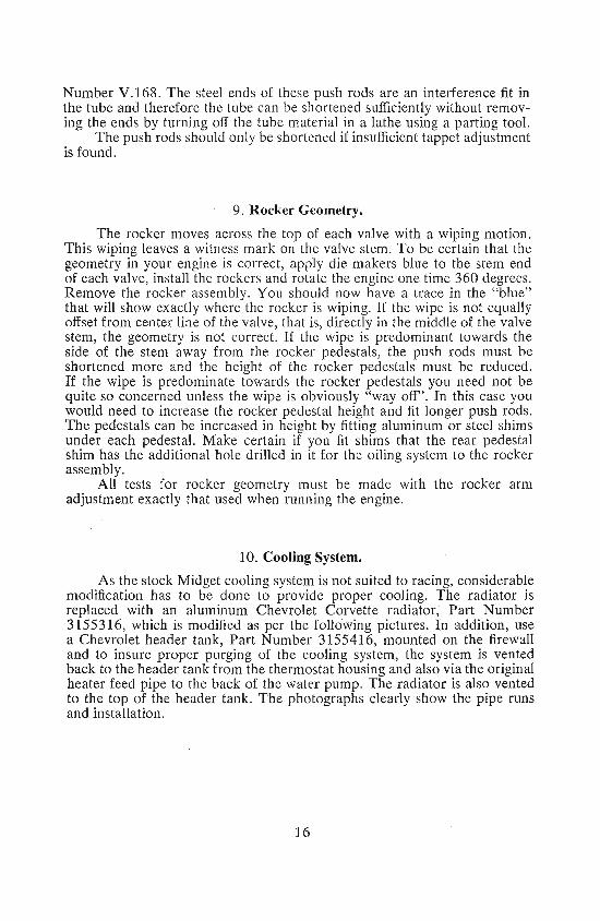
10. Cooling System.
As the stock Midget cooling system is not suited to racin g, considerablemodification has to be done to provide proper cooling. The radiator isreplaced with an aluminum Chevrolet Corvette radiator, Part Number315531 6, which is modified as per the following pictu res. In addition, usea Chevr olet header tank , Par t Number 3155416, mounted on the firewalland to insure proper purging of the cooling system, the system is ventedback to the header tank from the thermostat housing and also via the originalheater feed pipe to the back of the water pump. Th e radiator is also ventedto the top of the header tank. The photographs clearly show the pipe runsand installation.
16

MODIFIED RAD IATOR INLET
CLOSEUP OF RADIATOR HEADER TAN K
17

MODIFIED CORVETTE RADIATOR
RADIAT OR INSTALLATIONNOTE. TOP AIR BLEED HOSE ON THERMOSTAT HOUSING
18

11. Carburetor and Fuel System.
Th e carburetor modifica tions are qui te simple, i.e. all the elIDSSlOnpassages on the right hand side of the carburetor are blocked off either withaluminum plugs or epoxy. Fill the holes in the carburetor throat as smoothlyas possible thus reducing the amount of sanding and polishing afterwards .The throttle shaft is thinned down to approximately one-half its diameter byfiling flats on either side, pop-rivet the throttle in place, silver solder thewhole assembly, and afterwards lightly grind the pop-rivets flush with theshaft. Le ave the chok e assembly on the left side of the carbure tor intact asthis will assist starting. Th e fuel inlet valve is replaced with a 2.5 # 12855.Fuel pressures of 3.--: P .S.L can be used if the modified float spindle# B22561 and spring = B12 562 are fitted as in photo.
Th e needle holder in the piston can be rriodified to hold S.U. needlesby turning up a bush with a ~ 8" hole and pressing this into the piston bottom.Grind off the spring loaded plunger on the needle retainin g screw and solderin a piece of %2" rod to extend thro ugh the bush and lock the needle. Alternatively, S.U. needles can be modified to fit the Stromberg piston by forminga ball of silver solder on the needle shank to match the Stromberg design.The best needles to use are RC ='AUD 1287. Use velocity stack #V.619 .Remove the damper as embly from the top cap and use no oil in the piston .If the Stromberg needle holder is retained, turn it so as the slot does notline up with the set screw, or else it will move up or down on its own.Mixture is altered by moving the needle holder up to richen and down tolean . Initi al setting is with the needle holder up 1 ic" in the piston. Use thestock piston spring and fit the diaphragm with the vent hole to the rear.
The carburetor body is taper bor ed from stock size at the bridge to1.530" at the intake flange. Th e V. 619 velocity stack is altered to fit thenew intake dimension by cutt ing off the flare pipe at a point where itsinsidediam eter matches the 1.530" carbu retor dimension. The flange is then cutoff, bored out and rewelded to the flare pipe. The brid ge is lowered .100"by boring in the lathe. Smooth off the sharp edge of the br idge. The carburetor is mounted to the manifold with a o/lG" aluminum spacer plate withgrooves on either side to accept '0' r ings. The carburetor is held in placewith double coil spring washers and nylock nuts. Tigh ten only as much asnecessary to prevent air leaks.
12. Fuel Cell.
Use the A .T.L. 8 gallon economy fuel cell, obtainable from Aero TeeLabs Inc ., Hewson Avenue, Wald wick, New Jersey 07463 . Note: It isinstalled the right way up but the steel box supplied with it is inverted andthe flange is bolted to the trunk floor. This makes a neat and safe installation.The fuel pump is mounted on a bracket attached to the fuel cell flange andthe fuel lines are run through the car alongside the tunnel. This protects thelines in case of an off-course excurs ion. A fuel pressure regula tor should bemounted on the firewall to enable fuel pressure 'to be maintained at 3.5-5lbs. sq./in. We use a Holley Mod el P6145 fuel pu mp, which is a lowpressure high output type pump. This set up is imperative with a high
19

consumption single carbure tor. Mount the fuel pum p on a bracket attachedto the fuel cell flange.
13. Exhaust Header and Tail Pipe.
Use exhaust header, Part # V.616, and for maximum power make upa 2" diameter tail pipe to come level with the rear body panel. A slightimprovement at maximum speeds can be obtained by using a megaphoneto replace the last 13" of the tail pipe. The megaphone should measure4"x13"x2" and be made of 20 gauge mild steel.
Support the tail pipe on at least two flexible hangers and use two safetyloops around the pip e to hold it in the event of the flexible hangers letting go.Attach the tail pipe to the header with a slip joint welded to the tail pipe.Also weld two right angle brackets to the pipe and header, pre-drilled toaccommodate a securing bolt. This makes a very quickly detachable exhaustsystem.
14. Ignition System.
As the U.S. version of the Midget 1500 is fitted with Lucas electron icignition designed to meet emission requirements, for racing purposes it willbe necessary to change the distribu tor. Use distributor, Par t # 313232,which is a points type distribut or with the added advan tage of a mechan icaltachometer drive. This enables you to use a mechanical tachometer whichhas proven over the long run to be more reliable than its electro nic counterparts. To prepare the distributor , remove the top plat e and vacuum capsule,being careful not to rotate the top plate. Drill a hole through the top plate V8"in diameter at the point where the vacuum capsule push rod was located andcontinue to drill down thr ough the lower plate. Insert a V8" dia. x lI4 rr longpop rivet from the und erside of the lower plate to lock the top and lowerplates together. We are now left with mechanical advance only. Replace thepoints with a set of Mallory #100 points gapped at .015". We have foundthat these points give the best performance with very little point bounceat high RpMs. To seal the distributor where the vacuum capsule wasremoved, wrap the body with two turn s of good qu ality % tr wide plastic tape.Pierce the tape to allow installation of the t op plate/ cap lock retainingscrews. T he modified top plat e can now be re-installed. You will note wedo not recommend any modifications to the mechanical advance mechanismas the distributor is at full advance long before the RPM ran ge at which theengine will be operated is reached. Weare not, therefore, concerned withspecial advance curves. The only factor to consider is total adva nce. Withthe engine modifications previously described in the book, maximum powerwill be obtained with the ignition timed for 30 to 32 degrees at maximumadvance. It is a good idea to mark the front pulley with ignition timingmarks whilst you have the dial indicator and timing wheel set up to checkvalve timing. Accurately mark the T.D .C. point on the pulley and also markthe pulley at 30-32-34 degrees B.T.D.C. One word of caution: When installing the distributor, do not over-tighten the clamp bol t. Otherwise, you willdistort the distributor body.
20

Replace the stock resistor high tension wire with a good quality metalthread wire such as Packard 440 or Luc as Yellow Jacket and install "R ajah"straight type plug terminals on the high tensio n wire. Th ese plug terminalsare a high quality snap-on type which will stand a great deal of vibrationwithout falling off.
Th e choice of ignition coils is unlimited , however, we hav e used theMallory # 28675 with good success and this coil pro vides more than enoughfire for this engine.
SECTIONll
1. Gearbox and Clutch.
155206
15482 1
132292
To convert the gearbox to close-ratio gears for racing,parts are required:
216972 1st motion (input) shaft
213527 Laygear (cluster)
155207 3rd gear
the following
2nd gear
1st gear
Seal
To install these gears , follow the instruc tions in the Workshop Manualunde r the gearbox section. Before installing the 1st motion shaft, have alocal machine shop shorten it 1-. When assembling the 1st motion shaftdelete the shim washer between the snap ring and the bearing. T he sleeveon which the clutch release bearing assembly slides must be modified as perdrawing, to clear the larger diameter 1st mo tion shaft and to accept an oilseal, # 132292.
On late type Spitfire 1500 and Midget 1500 gearboxes, the mainshaftspigot bearing locat ion in the 1st motion shaft will have to be modifiedto accept the larger bearing, as per Fig. 2. On lat e Spitfire 1500 and Midget1500 it is also necessary to fit the earl y type main shaft thrust washer, whichis a select ive fit. See parts list for numbers. Also fit bush # 111423 and thrustwasher # 106262.
A suitable clutch plate with a bolt-in center can be obt ained fromMuell er Fabricators, 10872 Stanfor d Avenue, L ynwood, California 90262.Specify Spitfire conversion clutch 71/4 " with GT-6 center spline, whenordering.
Fig. 1
21
Fig. 2

SECTION III
SUSPENSION AND STEERING1. Front Shock Absorbers and Suspension.
In order to de-camber the front end, provide more advantageous movement of the shock absorber, and prevent piston bottoming with a loweredsupension, the comp etition shock arm has to be removed . This is a comparatively simple operation, pro vided you follow our instru ctions to thelett er.
Use a 'Snap -On' Pitman Arm Puller, # CJ89, to put a fairly heavy loadon the arm, then momentarily heat up the eye 180 degrees from the armwith a Heli-Arc tor ch. Thi s will expand the eye and allow you to removethe arm . Re-position the arm at 30 degrees from horizontal in the fullyraised position (stock position is 12 degrees). See photo for detailed view.Mark arm and shaft with an alignment mark then heat up the arm to expandit, pr ess it back on to the shaft and tighten the nut to 80 lbs. and refit thecotter pin. Whilst the arm is off the shock , it can be shortened % " andre-welded (Heli-Arc) as per photo.
The front suspension bushings are replaced with Derlin bushes whichat the time of writing are obtainable from Vari ous Imported Parts, 705Argonne Ave. , Sterling, VA. 22170. The front hubs should be conver ted totaper roller bearings, Timkin #30205 inner, and Timkin # 30303 oute r.Leave in the distance piece and shim to obtain zero preload or free play withthe nut torqued to 140 lbs. Check inner bearin g to make sure it bottomsagainst the spindle shoulder.
Th e steering column on the Group 44 car, is the stock inner columnsupported by a plain bearing on the dash panel, with the sliding joint weldedup and an MGB type universal joint , installed at the bottom. No modifications are made to the side steering arms or the rack assembly. Front Huffakersprings, Part # HAE 948 , are used with a free length of 7Y2" and have adiameter of 41h".
FRONT SWAY BAR MOUNT
22

RACE
RE-lOCATIO OF FRONT SHOCK ARMS
KING PIN OFFSET TOP BUSH.
23

RACING DASH ASSEMBLYNOTE. BEARING ATTACH MENT FOR STEERING COLUMN
2. Rear Shock Absorbers.
Group 44 cars use the MGB type fitted to adaptor plates made from% " aluminum plat e (see photo), or alternatively, the fact ory adjustableshocks can be used on the stock mount. Whichever meth od is chosen, theexisting links should be replaced with heim joints and adjustable links. Seephotos. As we also use the shock arm to trans mit sway bar reaction to theaxle, a fully adjustable rear sway bar can be made up from o/s " 304 stainlesssteel. See photo for details. The offset rear springs can be obtained fromthe suppliers listed in App endix II. Note that spacer bushes must be madeup to allow them to fit the stock spring mounts , and lowering blocks with alocating boss must also be made up. See photo for details.
The rear axle is located using a single adjustable link as per photo,equipped with heim joints. Sufficient adjustment must be allowed to enablethe axle to be adjusted to be parallel to the driveshaft position, in a loadedcondition, i.e, fuel and driver . Use BTA 940 axle shafts and Federal Mogul1207M bearings with the filling slot installed in the 12 o'clock position.
24

REAR SHOCK SHOWING MOUNTING PLATE
25

REAR SWAY BAR ASS Y. WITH SHOC K ASSE MBLERS ATTACHED
DRIVE SHAFT TUNNEL SHOWING AXLE LOCATOR MOUNTING
26

3. Rear Axle.
It has been found that most drivers today pr efer to drive with lockedrear ends as opposed to the rather expensive and sometimes unreliablelimited slip or locker types . Locking the Midget unit is quite simple. First .strip the unit and de-grease thoroughly. Remove the crown wheel andbearings from the dill box and cut two small wedges of scrap iron to wedgebetween the side gears and center pin. This insures that the side gears arehard up against the housing. Heat the whole assembly to cherry red andimmediately heli-arc the side gears to the housing (see photo). The assemblyshould now be allowed to air cool to prevent distortion. When re-assembling,stick to stock clearances as per the Workshop Manual. Use a 90W racinggear oil in both the rear axle and gear box which has an anti-foaming additive. The existing breather should be removed and a pipe fitting installedto enable a hose to be run up to a 1 pint catch tank in the trunk. To preventexcessive amounts of oil accumulating in the axle tubes, bailie the inside ofthe axle casing and provide flap drains. See photo.
REAR BRAKE BACK PLATE WITH VENT & LIGHTENING HOLES
27

REAR SPRING MOUNT WITH OFFSET SPACER
REAR AXLE LOWERING BLOCK & EXTENDED " U" BOLTS .
28

DETAI LS OF FRONT & REAR, REAR SPRING HANGERS,OFFSET SPACERS & SPRIN G CLAMP
DIFF. ASSY. SHOWING WELDED UP DIFF. BOX
29

LOWERING BLOCK TO AXLE LOCATION
REAR AXLE CASE WITH OIL BAFFLES
30
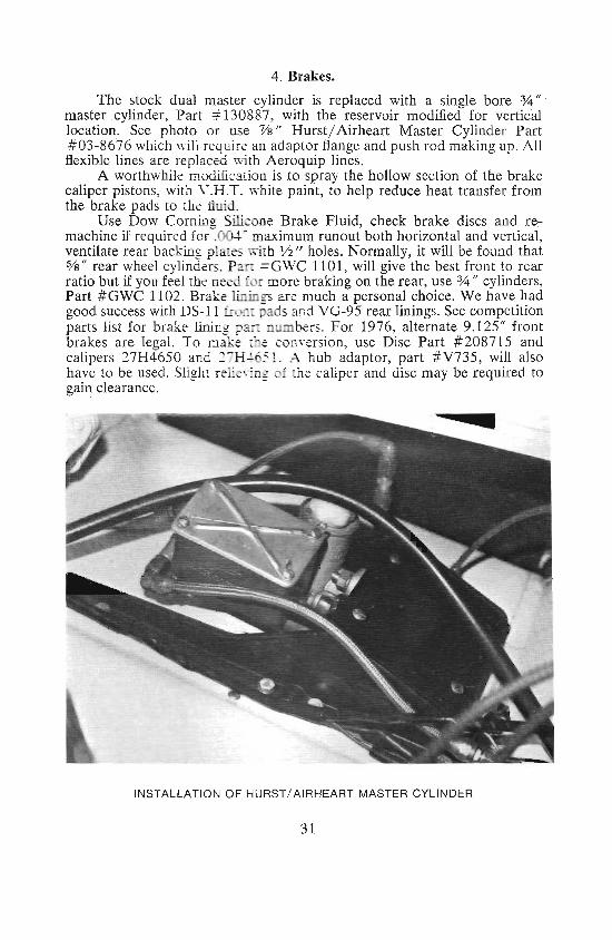
4. Brakes.
The stock du al master cylinder is replaced with a single bore %"master cylinder , Part # 130887, with the reservoir modified for verticallocation . See photo or use Ys" Hurst / Airheart Master Cylinder Part# 03-8676 wh ich will require an adaptor flange and push rod maki ng up. Allflexible lines are replaced with Aeroquip lin es.
A worthwhile modifi arion is to spr ay the hollow section of the brakecalip er pistons, with V.H.T. white paint, to help reduce he at tr ansfer fromthe brake pads to the fluid ,
Use Dow Comins Silicone Brake Fluid, check brake discs and re:ma chine if required for-:0 .-maximum runout both horizontal and vert ical,ventilate rear backing plates with Jh " hol es. Normally, it will be found tha t%" rear wheel cylin ders. Pan = GWC 1101 , will give th e best front to rearratio but if you feel the need for more braking on the rear, use % " cylinders,Par t #GWC 1102. Brake linin gs ar e much a person al cho ice . We have hadgood success with DS- i l front j ads and VG-95 rear linings. See competitionparts list for brake lining pa _ n mbers , For 1976, alternate 9.1 25 " frontbrakes are legal. To maxe " e conv ersion, use Disc Part #208715 andcalipers 27H 4650 and nH~ 5 . A hub adaptor, part # V735, will alsohave to be used. Slight elieving 0 the caliper and disc may be required togain cleara nce.
INSTA LLATION OF HURST/ AIRHEART MASTER CYLI NDER
31

Bu sh the Se ty,< o ClO\ e s
\ Se e tey:t)
CYLINDER BLOCK PREPARATION .BEFORE MACHINING S, EE TEXT PAGE 5.
32

APPENDIX A
Th e follo wing competition parts can be ordered through any Brit ish LeylandDealer. We regret that we cannot supply parts direc t from the Co mpetitionDepartment, however , we will be happ y to provide you with any techn ical information you may req uire.
P art No.
V. 175Y.1 IOV.624V. 687V. 549V. 731V.1 68V. 619148118S514082ARO 9875130148140987142647142648
BT A 535BT A 1223BTA 539BT A 940AHH 72 17AHH721 8AHT 56AHT57AJJ 3356AK M 326720 871527H 465027H 4651
V735
D~ption
"Carnshaft, B. 280 degrees, .409 " lift"Camshaft. --\.-6. 288 degrees, .391" lift"Camshaft. .'\-7. 298 degrees, .410" lift
''''Camshaft, .'\-8. 290 degrees, .465" liftCompetit ion valve springs & retainersCompetition valve springs & retainersPush rod set. alloy, (steel ends)Velocity stacksPistons fo r .o.ro- olsOil cooler kit (street use on ly )Oil coo ler. 16 row. competitionAdaptor (o il cooler installation )Unions fo r ada pto r ( 2 required)Camshaft bearing, outer (2 required)Camshaft bearing, inn er (2 required )Ge arbox-See Section II for convers ion to close-ratioRing gear/pinion , 3.727Ring gear/ pin ion, 3.9Ring gear! pinion , 4.22Competition axle shaftCompetition shock valve (front)Competition shoc k valve (rear)%" Anti-sway bar (front)lIJi(;" Anti-sway bar ( front )Installation kit for sway barsWorkshop Manu al9.125" Front brake discsBrake caliper, right handBrake caliper, left handHub adaptor (2 required)
" Use competition valve spring & retainer set , V. 549 .*"Use competition valve spring & retainer set, V. 731.
33

N OTE S
Li tho in U .S.A.Simax, N. Y.