Compatible High Definition receivers for the Italian …Compatible High Definition receivers for the...
188
HD Book DTT platform (Digital Terrestrial Television) Compatible High Definition receivers for the Italian market: baseline requirements Final 3.0 CONFINDUSTRIA RADIO TELEVISIONI
Transcript of Compatible High Definition receivers for the Italian …Compatible High Definition receivers for the...

HD Book
DTT platform (Digital Terrestrial Television) Compatible High Definition receivers for the Italian market: baseline requirements
Final 3.0
CONFINDUSTRIA RADIO TELEVISIONI


HD Book Collection


HD Book Final 3.0
DTT platform (Digital Terrestrial Television)
Compatible High Definition receivers for the Italian market:
baseline requirements
HD Book collection Volume 1
CONFINDUSTRIA RADIO TELEVISIONI

Important notice Individual copies of the present document can be downloaded from:
http://www.hdforumitalia.org The present document may be made available in more than one electronic version or in print. In any case of existing or
perceived difference in contents between such versions, the reference version is the Portable Document Format (PDF). In case of dispute, the reference shall be a printed copy provided by Associazione HD Forum Italia
Users of the present document should be aware that the document may be subject to revision or change of status. Information on the current status of this document is available at Associazione HD Forum Italia
If you find errors in the present document, please contact Associazione HD Forum Italia
Copyright Notification No part may be reproduced except as authorized by written permission.
The copyright and the foregoing restriction extend to reproduction in all media.
The content of this document takes on and refers to the Copyright law, as cited in article 70 and article 10 of Bern Treaty. For reproduction rights, Associazione HD Forum Italia remains at the disposal of the rights holders who could not be contacted.
All trademarks and logos mentioned herein belong to their respective owners. Associazione HD Forum Italia will not be held liable for any damages caused or alleged to be caused either directly or indirectly by this
document. Any eventual legal controversial will be disputed at Rome's Court of competent jurisdiction.
Front cover design by Marco Pellegrinato.
Editor copyright: © 2014 Associazione HD Forum Italia, on behalf of its founding members, and Confindustria Radio Televisioni, on
behalf of its founding members.
Published by Associazione HD Forum Italia. All rights reserved.

HD Book collection Volume 1 DTT platform - Final 3.0
HDBK01/HDFI/WG-T/TS/P/DTT/b3.0 - 3 -
Table of Contents 1. Foreword .......................................................................................................................13
1.1. Market outlook ...................................................................................................... 13 1.2. Technology outlook ............................................................................................... 14
1.2.1. HFR and HDR ...............................................................................................14 1.2.1.1. High Frame Rate (HFR) ............................................................................15 1.2.1.2. High Dynamic Range (HDR) ......................................................................15
1.2.2. HbbTV 2.0 .....................................................................................................15 1.2.3. Improvements in Audio Technologies ............................................................16
1.2.3.1. Audio Codec ETSI TS 103 190: AC-4 ........................................................16 1.2.3.2. Object-based audio ...................................................................................16
1.3. Compliance notation ............................................................................................. 17 1.4. Acknowledgments ................................................................................................. 17
2. Document History ..........................................................................................................19 3. References ....................................................................................................................25 4. Definitions and abbreviations ........................................................................................29
4.1. Definitions ............................................................................................................. 29 4.2. Abbreviations ........................................................................................................ 30
5. The HD-Books ...............................................................................................................35 5.1. Terminology and notation ...................................................................................... 36 5.2. Broadband Features ............................................................................................. 37
5.2.1. Broadband content and service protection ....................................................37 5.2.2. Broadband Application Security.....................................................................38
5.3. 3DTV Features ..................................................................................................... 38 5.4. Linkage with other organizations ........................................................................... 38 5.5. Graceful Degradation ............................................................................................ 38
6. Basic requirements ........................................................................................................39 6.1. Hardware requirements for the receiver ................................................................ 39
6.1.1. Terrestrial Front End & Signal Decoding .......................................................39 6.1.1.1. Mandatory features ...................................................................................39 6.1.1.2. Recommended features ............................................................................44 6.1.1.3. Optional features .......................................................................................45
6.1.2. Interaction Channel .......................................................................................45 6.1.2.1. Wireline interaction channel .......................................................................46 6.1.2.2. Mobile interaction channel .........................................................................49 6.1.2.3. Presentation of Interaction Channel Type to Applications ..........................50 6.1.2.4. User Instructions .......................................................................................50
6.1.3. Memory .........................................................................................................50 6.1.4. I/O Connectors ..............................................................................................51
6.1.4.1. Mandatory Connectors ..............................................................................51 6.1.4.2. Optional Connectors ..................................................................................53 6.1.4.3. Audio outputs matrix ..................................................................................55
6.2. Remote Control ..................................................................................................... 56 6.2.1. Introduction ...................................................................................................56 6.2.2. Overview .......................................................................................................57 6.2.3. Generic functional description of the remote control ......................................57 6.2.4. General Recommendations ...........................................................................57
6.2.4.1. The Main Remote ......................................................................................58 6.2.4.2. Single hand friendly ...................................................................................58 6.2.4.3. Clear structure ...........................................................................................58 6.2.4.4. Channel selection ......................................................................................58 6.2.4.5. TV controls ................................................................................................58 6.2.4.6. Now and Next ............................................................................................58

HD Book collection Volume 1 DTT platform - Final 3.0
HDBK01/HDFI/WG-T/TS/P/DTT/b3.0 - 4 -
6.2.4.7. Navigation keys .........................................................................................58 6.2.4.8. Dimensions ...............................................................................................58
6.2.5. The Numeric Pad ..........................................................................................58 6.2.5.1. Overall Function Description ......................................................................58 6.2.5.2. Requirements for the Numeric Pad ............................................................59
6.2.5.2.1 Time-out for channel selection ........................................................... 59 6.2.5.2.2 Labelling of Numeric Pad keys ........................................................... 59
6.2.6. Interactive Pad ..............................................................................................59 6.2.6.1. Overall Function Description ......................................................................59 6.2.6.2. Requirements for Interactive Pad ..............................................................59
6.2.7. The Navigation Pad .......................................................................................59 6.2.7.1. Overall Function Description ......................................................................59 6.2.7.2. Suggestions for Navigation Pad ................................................................60
6.2.8. The TV Pad ...................................................................................................60 6.2.8.1. Overall Function Description ......................................................................60 6.2.8.2. DGTVi Requirements ................................................................................60
6.2.9. The Player Pad .............................................................................................61 6.2.9.1. Overall Function Description ......................................................................61
6.3. Remote control keys detailed specifications .......................................................... 61 6.3.1. The Numeric Pad ..........................................................................................61 6.3.2. The Interactive Pad .......................................................................................61 6.3.3. The Navigation Pad .......................................................................................62 6.3.4. The TV Pad ...................................................................................................62 6.3.5. The Player Pad .............................................................................................63 6.3.6. Other Keys ....................................................................................................63
6.4. Interaction between (proprietary) receiver GUI and MHP applications .................. 64 6.5. Requirements for the “Undo” Function .................................................................. 64
6.5.1. Preface ..........................................................................................................64 6.5.2. General Requirements ..................................................................................64 6.5.3. States of the IRD ...........................................................................................64 6.5.4. Other groups’ proposals for key mapping ......................................................65 6.5.5. Keys and Labelling ........................................................................................65 6.5.6. Key mapping .................................................................................................65
6.6. Requirements for Text Entry Function ................................................................... 65 6.6.1. The present situation for text input in I-TV .....................................................65 6.6.2. Rules for « Request Focus » .........................................................................66 6.6.3. Text Entry General Requirements .................................................................66 6.6.4. Key Pad Suggested assignment for text entry ...............................................66
6.6.4.1. Standard Characters Subset .....................................................................67 6.6.4.2. Special Characters Subset ........................................................................67
6.6.5. Text Entry Functions .....................................................................................67 6.6.6. Text Entry Devices ........................................................................................68 6.6.7. Text Entry Layering .......................................................................................69 6.6.8. Text Entry Layering - Underlying Considerations ...........................................69 6.6.9. MHP applications and Text entry functionality ...............................................69
6.6.9.1. MHP applications and Text entry sample class ..........................................69 7. Service Information & Channel Selection ......................................................................71
7.1. DVB Locator ......................................................................................................... 71 7.2. SI and PSI Information .......................................................................................... 71
7.2.1. Notation .........................................................................................................71 7.2.2. Program Map Table (PMT) ............................................................................72
7.2.2.1. Multiple components of the same type ......................................................73 7.2.2.2. HD-specific elementary stream types ........................................................73 7.2.2.3. Supplementary Audio ................................................................................73
7.2.2.3.1 DVB solution ...................................................................................... 73

HD Book collection Volume 1 DTT platform - Final 3.0
HDBK01/HDFI/WG-T/TS/P/DTT/b3.0 - 5 -
7.2.2.3.2 Enhanced AC-3 solution ..................................................................... 73 7.2.2.4. AVC_video_descriptor ...............................................................................73
7.2.3. Network Information Table (NIT) ...................................................................74 7.2.3.1. Eacem Stream Identifier Descriptor (Eacem SD) .......................................74 7.2.3.2. Terrestrial delivery system descriptor ........................................................74
7.2.3.2.1 T2 Delivery System Descriptor ........................................................... 75 7.2.3.3. Other_frequency_flag ................................................................................75
7.2.4. Bouquet Association Table (BAT) ..................................................................75 7.2.5. Service Description Tables (SDT) .................................................................75
7.2.5.1. Service Types............................................................................................76 7.2.5.2. Running status ..........................................................................................77
7.2.6. Event Information Table (EIT) .......................................................................77 7.2.6.1. Event Information Descriptors ...................................................................77 7.2.6.2. Carriage of EIT ..........................................................................................78 7.2.6.3. Cross Carriage of EIT ................................................................................78 7.2.6.4. EIT schedule compression ........................................................................78
7.2.7. Summary of mandatory tables .......................................................................78 7.3. Private Data .......................................................................................................... 79
7.3.1. Logical Channel Descriptor ...........................................................................79 7.3.1.1. Descriptor_tag ...........................................................................................80 7.3.1.2. Service_id .................................................................................................80 7.3.1.3. Visible_service_flag ...................................................................................80 7.3.1.4. Reserved ...................................................................................................80 7.3.1.5. Logical_channel_number ..........................................................................80
7.3.2. The Logical Channel Numbers (LCN) ............................................................80 7.3.3. Network operator rules ..................................................................................81
7.3.3.1. Multiples LCNs for a single service ............................................................81 7.3.3.2. Invisible services .......................................................................................81 7.3.3.3. Service number zones ...............................................................................81
7.3.4. Receiver rules ...............................................................................................82 7.3.4.1. General rules .............................................................................................82 7.3.4.2. Definitions .................................................................................................82
7.3.4.2.1 Scan List ............................................................................................ 82 7.3.4.2.2 Service List ........................................................................................ 82 7.3.4.2.3 Master User List ................................................................................. 82 7.3.4.2.4 User Favourite List(s) ......................................................................... 83
7.3.4.3. Logical channel number zero .....................................................................83 7.3.4.4. Invisible services .......................................................................................83 7.3.4.5. Service List management ..........................................................................83
7.3.4.5.1 First initialisation................................................................................. 83 7.3.4.5.2 Adding new services .......................................................................... 84 7.3.4.5.3 Removing a service ............................................................................ 84
7.3.4.6. Master User List Management ...................................................................85 7.3.4.6.1 Creating the Master User List ............................................................. 85 7.3.4.6.2 Modifying the Master User List ........................................................... 85 7.3.4.6.3 Updating the Master User List ............................................................ 85 7.3.4.6.4 Renewing the Master User List .......................................................... 85
7.3.4.7. User Favourite List(s) ................................................................................85 7.3.4.8. The Preferences Zone ...............................................................................85 7.3.4.9. The Assignment Zone ...............................................................................85
7.3.5. Service variation options ...............................................................................86 7.3.5.1. Service regionalisation ..............................................................................86 7.3.5.2. Network re-configuration ...........................................................................86 7.3.5.3. Change of LCN numbering scheme ...........................................................86
7.3.6. HD Simulcast Logical Channel Descriptor .....................................................86

HD Book collection Volume 1 DTT platform - Final 3.0
HDBK01/HDFI/WG-T/TS/P/DTT/b3.0 - 6 -
7.3.6.1. Descriptor_tag ...........................................................................................87 7.3.6.2. Service_id .................................................................................................87 7.3.6.3. Visible_service_flag ...................................................................................87 7.3.6.4. Reserved ...................................................................................................87 7.3.6.5. Logical_channel_number ..........................................................................87 7.3.6.6. HD simulcast LCN operation .....................................................................87
7.4. Service-variation options ....................................................................................... 89 7.5. Receiver functions ................................................................................................ 89
7.5.1. Service Change .............................................................................................89 7.5.1.1. Audio language .........................................................................................89 7.5.1.2. CA controlled services ...............................................................................89
7.5.2. Service Not Available ....................................................................................89 7.5.3. Active Format Descriptor ...............................................................................89
7.5.3.1. Syntax and Semantics ...............................................................................90 7.5.3.2. Valid Values for Descriptor ........................................................................90 7.5.3.3. Behaviour of receiver in presence of AFD .................................................90 7.5.3.4. Analogue output of the receiver .................................................................90 7.5.3.5. AFD and HDMI ..........................................................................................90
7.6. Network Connection (Tuning) ................................................................................ 91 7.6.1. General Requirements ..................................................................................91 7.6.2. First Installation Procedure ............................................................................91 7.6.3. Manual Full Scan Procedure .........................................................................92
7.6.3.1. Update ......................................................................................................92 7.6.3.2. Re-install ...................................................................................................92
7.6.4. Manual Scan Procedure (Single Channel) .....................................................92 7.6.5. Automatic full scan (Automatic service list update) ........................................92
7.6.5.1. Default settings for automatic scan ............................................................93 7.6.5.2. Handling of duplicate services ...................................................................94 7.6.5.3. Automatic Ordering of Channels and Services in absence of LC descriptor acquisition ..................................................................................................................94
7.6.6. Network evolution ..........................................................................................94 7.6.7. Default channel numbering of services ..........................................................94
7.7. User interface to the SI carried data ...................................................................... 94 7.7.1. Timer .............................................................................................................95 7.7.2. Access to the Service list...............................................................................95 7.7.3. Access to the list of service-bound MHP applications ....................................96
8. Resident Software and API ...........................................................................................97 8.1. Services ................................................................................................................ 97
8.1.1. Video Dripping ...............................................................................................97 8.1.2. Teletext .........................................................................................................97 8.1.3. Subtitling .......................................................................................................97
8.1.3.1. DVB Subtitling ...........................................................................................97 8.1.3.2. Teletext Subtitling ......................................................................................98
8.2. Resident Software ................................................................................................. 98 8.2.1. Resident Manufacturer Specific Applications .................................................98
8.2.1.1. Navigator ...................................................................................................98 8.2.1.1.1 Handling of input events by the Navigator .......................................... 98
8.2.2. Parental Control ............................................................................................98 8.3. Multimedia Home Platform (MHP) ......................................................................... 99
8.3.1. MHP Profile ...................................................................................................99 8.3.2. Application Manager .................................................................................... 100
8.3.2.1. Autostart Applications .............................................................................. 100 8.3.2.2. Interaction between Resident and Downloaded Applications ................... 101
8.3.3. SDRAM Memory Management .................................................................... 101 8.3.4. Receiver properties ..................................................................................... 101

HD Book collection Volume 1 DTT platform - Final 3.0
HDBK01/HDFI/WG-T/TS/P/DTT/b3.0 - 7 -
8.3.5. Behaviour with mixed SD/HD applications ................................................... 102 8.3.6. Guidelines for AIT URL ............................................................................... 102 8.3.7. Inter-Xlet Communication (IXC) API ............................................................ 103 8.3.8. Advanced graphics API ............................................................................... 103
8.4. Application Environment(s) for broadband media delivery ................................... 103 8.4.1. Procedural Application Environment ............................................................ 103
8.4.1.1. APIs for Streamed CoD ........................................................................... 103 8.4.1.1.1 Player operations ............................................................................. 104 8.4.1.1.2 Time-setting operations .................................................................... 105 8.4.1.1.3 Audio language ................................................................................ 106 8.4.1.1.4 Streamed CoD control ...................................................................... 106 8.4.1.1.5 Subtitles control................................................................................ 106 8.4.1.1.6 Parental Control ............................................................................... 106
8.4.1.2. APIs for Download CoD ........................................................................... 106 8.4.1.3. DRM APIs ............................................................................................... 106 8.4.1.4. OTT content referencing API ................................................................... 107
8.4.2. Other Application Environments .................................................................. 107 8.5. Resident applications related to broadband media delivery ................................. 107
8.5.1. History ......................................................................................................... 107 8.5.2. Bookmarks .................................................................................................. 108
8.6. Maintenance and Upgrade .................................................................................. 108 8.6.1. Automatic software upgrade ........................................................................ 108 8.6.2. Over The Air Software Update .................................................................... 109
8.6.2.1. Recommendations for SSU operation ..................................................... 110 9. Smart cards, CAs, DRMs and Security ........................................................................ 111
9.1. Smart Cards ........................................................................................................ 111 9.1.1. Conditional Access ...................................................................................... 111 9.1.2. Embedded CA(s) ......................................................................................... 111 9.1.3. Common Interface ....................................................................................... 111
9.1.3.1. Physical engagement .............................................................................. 111 9.1.3.2. Backward compatibility ............................................................................ 111 9.1.3.3. CA-API .................................................................................................... 111 9.1.3.4. Implementation guidelines ....................................................................... 112
9.1.3.4.1 General ............................................................................................ 112 9.1.3.4.2 High Level MMI ................................................................................ 112
9.1.4. Non-CA Services ......................................................................................... 113 9.2. Common Encryption ........................................................................................... 113 9.3. Broadband Applications Security (BAS) .............................................................. 115
9.3.1. BAS requirements ....................................................................................... 115 9.3.2. BAS solution outline .................................................................................... 115 9.3.3. BAS signalling ............................................................................................. 116 9.3.4. BAS permissions ......................................................................................... 116
9.3.4.1. PRF Extensions ....................................................................................... 117 9.3.4.2. Request validation procedures ................................................................ 118
9.3.5. Impact of BAS on broadcast applications .................................................... 120 9.4. Certificate Management ...................................................................................... 121
9.4.1. Certificate Revocation ................................................................................. 121 9.4.2. Root certificate management ....................................................................... 121 9.4.3. Certificate store exposure............................................................................ 121 9.4.4. White list exposure ...................................................................................... 122
10. Accessories and Setup ............................................................................................ 123 10.1. Receiver Accessories.......................................................................................... 123 10.2. Power Supply / Voltage ....................................................................................... 123 10.3. Low-power mode ................................................................................................ 123
11. Default settings ........................................................................................................ 125

HD Book collection Volume 1 DTT platform - Final 3.0
HDBK01/HDFI/WG-T/TS/P/DTT/b3.0 - 8 -
A DVB-T2 Performance Tables ...................................................................................... 129 A.1 FEF and Auxiliary streams .................................................................................. 129 A.2 C/N Performance ................................................................................................ 130
A.2.1 Behavior in presence of echoes inside the guard interval ................................ 133 A.2.2 Behavior in presence of echoes outside the guard interval .............................. 133 A.2.3 Behavior in presence of co-channel interference ............................................. 134 A.2.4 Behavior in presence of digital signal in other channels .................................. 134 A.2.5 Behavior in presence of co-channel analogue signals ..................................... 134
A.3 List of some DVB-T2 modes for different types of networks and receiving conditions ....................................................................................................................... 135
B Remote control ............................................................................................................ 137 B.1 The need for specifications ................................................................................. 137 B.2 Keys and Key Events .......................................................................................... 137
B.2.1 The MHP minimum specification ..................................................................... 137 B.2.2 E-Book ver. 1 .................................................................................................. 138 B.2.3 DTG UK .......................................................................................................... 139 B.2.4 The CEI Specification ...................................................................................... 139 B.2.5 The NorDig Unified Specification ..................................................................... 140
B.2.5.1 The Remote Control and Remote Keyboard ............................................ 140 B.3 Summary of proposals for Undo/Exit keys ........................................................... 141 B.4 Easy TV .............................................................................................................. 141
B.4.1 Easy-TV: a research by the ITC, Methodology ................................................ 141 B.4.2 Easy-TV: Most common issues with the remote control .................................. 142
C DVB-T Minimum input level ......................................................................................... 143 D Void ............................................................................................................................. 145 E Text entry sample class ............................................................................................... 147 F Allocation and usage of SI codes in Italy ..................................................................... 149
F.1 Allocation of SI codes ......................................................................................... 149 F.2 Original_network_id ............................................................................................ 149 F.3 Transport_stream_id ........................................................................................... 150
F.3.1 Recommended allocation of codes ................................................................. 150 F.3.2 National Codes already in use......................................................................... 151
F.4 Service_id ........................................................................................................... 151 F.5 Network_id .......................................................................................................... 151 F.6 Network Name .................................................................................................... 152
G Void ............................................................................................................................. 153 H MHP CA API Implementation Guidelines for non CA smart cards ............................... 155
H.1 Purpose .............................................................................................................. 155 H.2 Package it.dtt.ca ................................................................................................. 155
H.2.1 CaManager ..................................................................................................... 155 H.2.1.1 Constructor .............................................................................................. 155 H.2.1.2 getCAProvider ......................................................................................... 155 H.2.1.3 getClient .................................................................................................. 155 H.2.1.4 getSlots ................................................................................................... 155
H.2.2 CaManagerFactory ......................................................................................... 155 H.2.2.1 closeSession ........................................................................................... 156 H.2.2.2 getInstance .............................................................................................. 156 H.2.2.3 openSession ........................................................................................... 156
H.2.3 CaObject ......................................................................................................... 156 H.2.3.1 Constructors ............................................................................................ 156 H.2.3.2 Methods .................................................................................................. 156
H.2.4 CaSession....................................................................................................... 156 H.2.4.1 Constructors ............................................................................................ 156 H.2.4.2 Methods .................................................................................................. 156
H.2.5 Slot ................................................................................................................. 156
HD Book collection Volume 1 DTT platform - Final 3.0
HDBK01/HDFI/WG-T/TS/P/DTT/b3.0 - 9 -
H.2.5.1 Constructors ............................................................................................ 156 H.2.5.2 addSlotListener ....................................................................................... 157 H.2.5.3 getSlotID ................................................................................................. 157 H.2.5.4 getSmartCard .......................................................................................... 157 H.2.5.5 getStatus ................................................................................................. 157 H.2.5.6 removeSlotListener ................................................................................. 157
H.3 Package it.dtt.ca.event ........................................................................................ 157 H.3.1 CaEvent .......................................................................................................... 157 H.3.2 SlotEvent ........................................................................................................ 157 H.3.3 SlotListener ..................................................................................................... 158 H.3.4 SlotEventReceived .......................................................................................... 158
H.4 Example .............................................................................................................. 158 I The new SATSA target ................................................................................................ 161
I.1 Introduction ......................................................................................................... 161 I.2 Proposed solution ............................................................................................... 161 I.3 Solution advantages ........................................................................................... 161 I.4 An example ......................................................................................................... 161
J EIT schedule compression .......................................................................................... 163 J.1 Introduction ......................................................................................................... 163 J.2 Compression algorithm ....................................................................................... 163
K Streaming monitoring API ............................................................................................ 165 L OTT content referencing API ....................................................................................... 167 M 2D service compatibility within 3DTV ........................................................................... 169
M.1 Introduction ......................................................................................................... 169 M.2 3DTV use cases.................................................................................................. 169 M.3 Implementation of 2D service compatibility ......................................................... 170
N PRF Example (Informative) ......................................................................................... 173 N.1 Introduction ......................................................................................................... 173 N.2 Example .............................................................................................................. 173
O DRM Agent as a system resource (Informative) .......................................................... 175 O.1 Introduction ......................................................................................................... 175 O.2 System resource declaration ............................................................................... 175 O.3 Verification phase ............................................................................................... 175
P XML schema and example for BAS white list .............................................................. 177 P.1 XML schema ....................................................................................................... 177 P.2 Example .............................................................................................................. 178
Q Special PAE provisions for DASH Live (Dynamic MPD) case ...................................... 181 Q.1 Definitions ........................................................................................................... 181 Q.2 Content duration ................................................................................................. 181 Q.3 Getting media presentation time ......................................................................... 181 Q.4 Setting media presentation time .......................................................................... 181 Q.5 Pausing and resuming a media presentation ...................................................... 182

HD Book collection Volume 1 DTT platform - Final 3.0
HDBK01/HDFI/WG-T/TS/P/DTT/b3.0 - 10 -
Tables Table 1: Mandatory features table ........................................................................................44 Table 2: Recommended features table .................................................................................44 Table 3: Optional features table ............................................................................................45 Table 4: Wireline interaction channel features ......................................................................47 Table 5: Container/media compatibility matrix ......................................................................48 Table 6: File extensions and MIME types for the various container formats ..........................49 Table 7: Interaction channels values ....................................................................................50 Table 8: Memory capacity requirements ...............................................................................50 Table 9: Mandatory connectors table ....................................................................................53 Table 10: Optional connectors table .....................................................................................55 Table 11: Audio channel mapping ........................................................................................56 Table 12: The Numeric Pad ..................................................................................................61 Table 13: The Interactive Pad...............................................................................................61 Table 14: The Navigation Pad ..............................................................................................62 Table 15: The TV Pad ..........................................................................................................63 Table 16: The Player Pad .....................................................................................................63 Table 17: Other keys ............................................................................................................63 Table 18 : Standard Character subset ..................................................................................67 Table 19: Special Character Subset .....................................................................................67 Table 20: Text Entry Rules ...................................................................................................68 Table 21: Symbols notation as per E-Book ...........................................................................72 Table 22: Program descriptors (PMT) ...................................................................................72 Table 23: Elementary stream descriptors (PMT)...................................................................72 Table 24: Network descriptors (NIT first loop) .......................................................................74 Table 25: Transport stream descriptors (NIT second loop) ...................................................74 Table 26: Service descriptors ...............................................................................................75 Table 27: Event Information Descriptors ...............................................................................77 Table 28: List of mandatory tables ........................................................................................79 Table 29: Private SI recognised in the E-Book .....................................................................79 Table 30: Syntax of the logical channel descriptor ................................................................80 Table 31: Logical channel number ........................................................................................80 Table 32: Syntax of the HD simulcast logical channel descriptor ..........................................87 Table 33: Default settings for automatic scan .......................................................................94 Table 34: Text Field Lengths ................................................................................................95 Table 35: Application Manager expected behaviour ........................................................... 100 Table 36: Default settings for auto software upgrade .......................................................... 109 Table 37: Protected format/media compatibility matrix........................................................ 114 Table 38: File extensions and MIME types for the various protected formats ..................... 114 Table 39: HTTPS applicability to BAS requirements ........................................................... 116 Table 40: Accessories ........................................................................................................ 123 Table 41: Default settings summary table ........................................................................... 126 Table 42: FEF test signal .................................................................................................... 129 Table 43: Auxiliary streams test signal ............................................................................... 130 Table 44: Example of maximum required C/N and sensitivity for QEF reception at TS output
(PP2 and FFT size 32KE) ............................................................................................ 131 Table 45: Example of maximum required C/N and sensitivity for QEF reception at TS output
(PP4 and FFT size 32KE) ............................................................................................ 131 Table 46: Example of maximum required C/N and sensitivity for QEF reception at TS output
(PP7 and FFT size 32KE) ............................................................................................ 132 Table 47: Ricean channel definition .................................................................................... 133 Table 48 QEF reception for echoes outside the guard interval for PP4 ............................... 133 Table 49 QEF reception for echoes outside the guard interval for PP2, GI 1/16, 7MHz ...... 134

HD Book collection Volume 1 DTT platform - Final 3.0
HDBK01/HDFI/WG-T/TS/P/DTT/b3.0 - 11 -
Table 50 QEF reception for echoes outside the guard interval for PP2, GI 1/8 ................... 134 Table 51: Test set-up (PP4) for pre-echoes and echoes outside the guard interval
(informative) ................................................................................................................ 134 Table 52: Test set-up (PP2) for pre-echoes and echoes outside the guard interval
(informative) ................................................................................................................ 134 Table 53 Carrier to Interference, C/I (dB) for QEF reception, when DVB-T2 signal is
interfered with by an analogue TV carrier. ................................................................... 135 Table 54: List of some DVB-T2 Modes ............................................................................... 135 Table 55: Minimum set of input events (G3) ....................................................................... 137 Table 56: E-Book v.1.9 ....................................................................................................... 138 Table 57: CEI Specification; CT 100, Progetto di Guida ..................................................... 139 Table 58: The NorDig Unified Specification; B.2.5. ............................................................. 140 Table 59: The NorDig IRD Key Events table (par 16,2,5: Mapping of Key Events) ............. 141 Table 60: Summary of proposals for Undo/Exit keys .......................................................... 141 Table 61: DVB-T minimum input levels (dBm) .................................................................... 143 Table 62: Text Entry Sample Class .................................................................................... 148 Table 63: Allocation of TS_IDs in Italy ................................................................................ 151 Table 64: National TS_IDs in use ....................................................................................... 151 Table 65: Network_ids of interest ....................................................................................... 152 Table 66: H.264/AVC signalling for service compatible modes of frame compatible plano-
stereoscopic 3DTV services ........................................................................................ 170 Table 67: Expected IRD behaviour for 2D service compatible 3DTV transmissions ............ 171

Page intentionally left blank

HD Book collection Volume 1 DTT platform - Final 3.0
HDBK01/HDFI/WG-T/TS/P/DTT/b3.0 - 13 -
1. Foreword Since 2005, the High Definition Television formats, 720p and 1080i, have entered the European satellite TV broadcasting market, with a wide offering of tens of HDTV channels provided by different Pay TV aggregators, such as Sky Italy with an offering of HDTV Sport channels. The Italian Analogue Switch-Off (ASO) process, which started during 2008 in Sardinia, has been completed on July the 4th 2012 in Sicily. Thanks to the new frequencies progressively made available in all-digital areas Italian broadcasters have experienced SD/HD simulcast services, both up-scaled SD contents already available on standard TV transmissions as well as using genuine HD contents. The vast majority of TV sets currently off the shelf are characterised by screen displays larger than 32 inches, with progressive scanning, panoramic view geometry (16/9) and compatible with HDTV formats and resolutions. New high-definition audio-visual sources such as media players for home video, BluRay disc players, HDTV and UHDTV cameras, video game consoles, as well as high-definition television programs, are designed to accurately reproduce high-quality contents, when connected to an HDTV display. In perspective, “today HDTV is moving to become the standard definition of tomorrow”. Based on this premise, it is important to continue and to evolve the migration route from SD to HD, aiming to promote the widespread diffusion of free to air HDTV programming. This matches the increased quality of large screen displays and TV sets as well as the increasing demand coming from new experienced customers. Production and transmission of HD contents has become a need for a successful competitive positioning of Italy in the worldwide digital television market. There is potentially a serious risk of losing relevant market quotes in the promotion of Italian culture, in an industrial context where large European and extra-European entities are rapidly progressing. Appealing hi-quality content productions, like those necessary for a successful offering of innovative technologies like HDTV, require huge investments. Broadcasters are considering SD/HD simulcasting a viable start towards the complete turnover of SD programmes into HD ones, but they know that a complete refurbishing and reengineering of the entire production, packaging and delivery platform has to occur for a broad diffusion of genuine HDTV services. In the meanwhile, on one hand new innovative technologies in content definition enhancement, notably the 4K format (UHDTV), are progressively emerging as the new Television benchmark, whilst on the other hand terrestrial spectrum resources devoted to television services are unavoidably going to shrink in the near/mid-term future.
1.1. Market outlook CE industry is particularly committed to boost sales of increasingly larger screen displays in order to maintain a steady cash flow thanks to a constant and rapid renewal cycle of TVs’ installed base. For this purpose they undertook, through their major category association in Europe, EICTA (European Industry Consumer Technical Association, now DIGITALEUROPE), the initiative of creating some licensed labels, corresponding to a precise set of technical requirements.

HD Book collection Volume 1 DTT platform - Final 3.0
HDBK01/HDFI/WG-T/TS/P/DTT/b3.0 - 14 -
First labels of this kind were launched back in 2005: HD Ready (for TVs) and HDTV (for TVs and STBs) and their counterparts in 1080p format. Displays or Video Projectors Receivers
More recently, in 2014, to inform consumers that the display device they are considering buying is compatible with all major sources of Ultra HD content and that it will be able to display this content in Ultra HD format, DIGITAL EUROPE has introduced a new label devoted to Ultra High Definition (3840x2160 pixels) display devices. The new label timely targets the first generation of UHD displays already available in retail shops. In fact, despite the current very limited availability of UHD contents and services, in the last year UHD displays have literally boomed, moving from niche to mass market products, with prices as low as €1,000.
1.2. Technology outlook HD Book 3.0 sets the requirements for the adoption of the new HEVC codec in compliant receivers that allows a further increase in efficiency compared to the previous compression techniques. By combining, in any given terrestrial receiver, the new HEVC compression techniques with the second generation terrestrial standard, DVB-T2, the efficiency improvement factor is about 3 times compared to the current distribution system (DVB-T and H.264/AVC). This dramatic increase in efficiency can be a formidable boost for quality improvement in television, making the introduction of the Full HDTV format (1080p50) feasible today and the Ultra HD format (UHDTV) in the near future. The technologies included in this volume represent the state-of-the-art available today in the market for television receivers. In the following a few other emerging technologies and standards are introduced that will likely become part of the HD-Books toolbox in future releases.
1.2.1. HFR and HDR The technological trend for the development of UDHTV format passes through the so-called “UHDTV Phase 2”, whose exact definition and standardization have just started in DVB. UHDTV Phase 2 calls for new technologies related to the improvement of television pictures quality not only increasing by 4 times the spatial resolution of HDTV format but also leveraging two additional techniques. Firstly, by increasing the temporal resolution, e.g. doubling the number of frames per second (HFR, High Frame Rate), so achieving better motion portrayal. Secondly, with the introduction of a significant increase in dynamic range of the luminance variations (HDR, High Dynamic Range).
HD Book collection Volume 1 DTT platform - Final 3.0
HDBK01/HDFI/WG-T/TS/P/DTT/b3.0 - 15 -
The use of HFR and HDR, together with the adoption of an extended colour gamut (BT2020 colorimetry), will enhance the TV experience far beyond the current user perception. A number of activities are taking place in various organizations (SMPTE, ITU, DVB, HDMI, EBU, MPEG) to enable a viable commercial launch of UHDTV Phase 2. It will require a number of changes to occur, involving not only manufacturers but also broadcasters and content providers, who will have to enhance accordingly their own production and delivery chains. Italian broadcasters and content providers are taking steps in this direction.
1.2.1.1. High Frame Rate (HFR) HDTV format is currently rated to 50/60 fps which is not ideal for satisfactory rendering of fast moving pictures (i.e. Sports). UHDTV resolution is 4 times larger than HDTV and consequently the definition of fast moving pictures become further penalized. HFR technology allows frame rates up to 100 fps (or 120 fps), reducing the “judder” and making pictures look like more real life.
1.2.1.2. High Dynamic Range (HDR) So far, the dynamic range of a normal TV display is about 100:1, while the peak luminance is between 200 and 400 cd/m2 in typical domestic environment. With HDR techniques and HDR capable displays, much higher dynamic range as up to 10000:1 and peak luminance of 4000 cd/m2 can be reached, with a more compelling user experience.
1.2.2. HbbTV 2.0 The Italian broadcasters have chosen MHP as interactive middleware back in 2003 for the introduction of digital terrestrial television (DTT) in Italy. After years of intense specification activity, the DVB standard middleware for interactivity in Europe was at that time enthusiastically supported by the Industry. In 2013, although a decline in total sales, the percentage of MHP products sold in Italy, nowadays mostly connectable TV sets, has increased. According to GfK data processed by Mediaset Lab, out of 73.1 million DTT receivers sold in Italy since 2004 (43.3M iDTVs, 29.8 STBs), the overall sell-out of MHP devices in Italy at the end of 2013 was as follows:
• Connectable HD STBs: 361.000 • Connectable TV sets: 2.242.000 • 256.000 connectable TV sets sold in 2010, without streaming capability • Over 10M first-generation SD STBs without broadband capability
Broadcast MHP applications have been on air in Italy since 2003, addressing almost any possible domain (T-Government, T-Banking, T-Betting, T-Tourism, ...). A dozen of MHP-based free, premium and free OTT Catch-up TV & VoD services have been available on the Italian horizontal platform (DTT and Tivùsat) since 2010 to a growing number of compatible devices. According to forecasts of Confindustria Radio Televisioni (CRTV) members, by the end of 2015 the overall sell-out of full-featured connectable MHP devices in Italy should exceed 6M units. At the same time HbbTV (Hybrid broadcast broadband TV) standard has been adopted in most other European countries. Following the recent announcements that the other large non-HbbTV country in Europe, UK, is considering to move to HbbTV, Italian broadcasters have decided to announce their own plans in the same direction. Italian broadcasters plan to adopt the new HTML5-based HbbTV 2.0 specification, defining a suitable migration path for the replacement of actual MHP middleware and related services. Earliest HbbTV 2.0 compliant receiver may become available in 2016, while mass adoption of such receivers is expected to occur presumably by 2017.

HD Book collection Volume 1 DTT platform - Final 3.0
HDBK01/HDFI/WG-T/TS/P/DTT/b3.0 - 16 -
1.2.3. Improvements in Audio Technologies HD-Book DTT 3.0 already includes a selection of audio codec possibilities together with some usage recommendations, in particular providing guidance for DVB-T2 services when deployed alongside advanced video codecs like H.264/AVC and HEVC. Having said the above it must be noted that the currently specified codecs are at best eight to ten years old and that there are some clear technological trends shaping up aimed to provide clear improvements in many areas with next generation audio codecs. Much improved compression efficiency, better accessibility, dialogue enhancement, intelligent loudness management and new experiences ensured by object-based audio should all be part of what modern audio codecs will deliver; audio encoding and reliability has to achieve comparable enhancements to what possible with H.264/AVC and HEVC for the cost effective rollout of enhanced experiences and services.
1.2.3.1. Audio Codec ETSI TS 103 190: AC-4 After the widespread diffusion of AC-3 format and of its EAC-3 successor, the AC-4 audio codec standard (ETSI TS 103 190) has been designed to go beyond providing simple compression efficiency. In fact AC-4 enables new, more immersive and personalized consumer audio experiences in the future. Users will be able to hear what the football match sounds like from the stands or the field and experience the kind of sound that transports them right to the centre of the action, whether they are playing a game or watching a movie. Solving several key issues currently facing the industry, the main benefits of AC-4 include: • Intelligent Loudness: Fully automated loudness management means more precise
control and eliminates problems with cascaded processing. It acts across a wide range of devices and applications (home theatre to mobile) and can be configured to align with numerous worldwide standards and/or recommendations.
• Advanced Dialogue Enhancement: End-users can have control of the dialogue level in relation to other sounds in the programme - suiting individual hearing needs and preferences.
• Advanced Accessibility: Service providers can easily and efficiently deliver secondary audio in 5.1 surround sound for the visually impaired without doubling the file size or bitrate.
• A/V Frame Alignment: AC-4 is the first emission audio format that allows the audio frame sizes to precisely match the video frame size. This allows the AC-4 data stream to be edited/spliced at video frame boundaries to maintain synchronization without the need to decode and re-encode the audio.
• Bandwidth Efficiency: AC-4 utilizes state-of-the-art compression techniques that provide significant bandwidth savings or higher quality in stereo and surround sound
AC-4 Part 1 has been already standardized in ETSI and is about to be included in the DVB reference specification for audio and video codecs (TS 101 154). AC-4 Part 1 is a channel-based codec which includes coded audio frame alignment with video framing, dialogue enhancement, seamless switching of bitrates and channel configurations, advanced loudness and dynamic range management, additional compression efficiency.
1.2.3.2. Object-based audio “Objects” in object-based audio could be compared with the individual elements in a conventional mix. On the other hand, the codecs offered for object-based audio include the ability, on the broadcaster’s or the viewer’s part, to put individual audio objects or elements, into specific speakers, to turn individual channels on and off, to change their volume levels

HD Book collection Volume 1 DTT platform - Final 3.0
HDBK01/HDFI/WG-T/TS/P/DTT/b3.0 - 17 -
relative to the other audio components, and, in some cases, to choose between alternate channels, such as multiple announcer streams. If object-based audio would catch on, it could change the technical topography of the living room in much the same way that 5.1 surround did a decade ago. It’s important to distinguish between dynamic object-based audio, where things are constantly moving around, and static object-based audio, where individual objects are in a specific place but can be turned on or off or have their volume varied by the viewer. Object-based audio side products are dialogue enhancement and better delivery efficiency through seamless switching of bitrates for different objects and single transmission with adaptation to the renderer, including evolved loudness and dynamic range management.
1.3. Compliance notation A word on the vocabulary: the use of shall, must, should, may is often baffling for non native English speakers. We have chosen to follow the IETF (Internet Engineering Task Force) which in its RFC 2119 states: 1. MUST: This word, or the terms "REQUIRED" or "SHALL", means that the definition is an absolute requirement of the specification. 2. MUST NOT: This phrase, or the phrase "SHALL NOT", mean that the definition is an absolute prohibition of the specification. 3. SHOULD: This word, or the adjective "RECOMMENDED", means that there may exist valid reasons in particular circumstances to ignore a particular item, but the full implications must be understood and carefully weighed before choosing a different course. 4. SHOULD NOT: This phrase, or the phrase "NOT RECOMMENDED" mean that there may exist valid reasons in particular circumstances when the particular behaviour is acceptable or even useful, but the full implications should be understood and the case carefully weighed before implementing any behaviour described with this label. 5. MAY: This word, or the adjective "OPTIONAL", means that an item is truly optional. One vendor may choose to include the item because a particular marketplace requires it or because the vendor feels that it enhances the product while another vendor may omit the same item. “ N.B. Throughout this document “MANDATORY” is also often used as a “REQUIRED” synonym.
1.4. Acknowledgments The persons that have contributed to the D-Book first and then to the HD-Book DTT are so numerous we would shortly run out of space if we tried to thank them individually. The HDFI / CRTV Joint Technical Group can only extend its gratitude to all of them and repeat that without them, this work could not have been completed. Of course, all errors and omissions are the sole responsibility of the editors and of the HD Forum Italia. Manufacturers, through their constructive remarks and questions have played a major role in helping us to clarify and improve many points of the specification. Let them be thanked here.
October 2014

Page intentionally left blank
HD Book collection Volume 1 DTT platform - Final 3.0
HDBK01/HDFI/WG-T/TS/P/DTT/b3.0 - 19 -
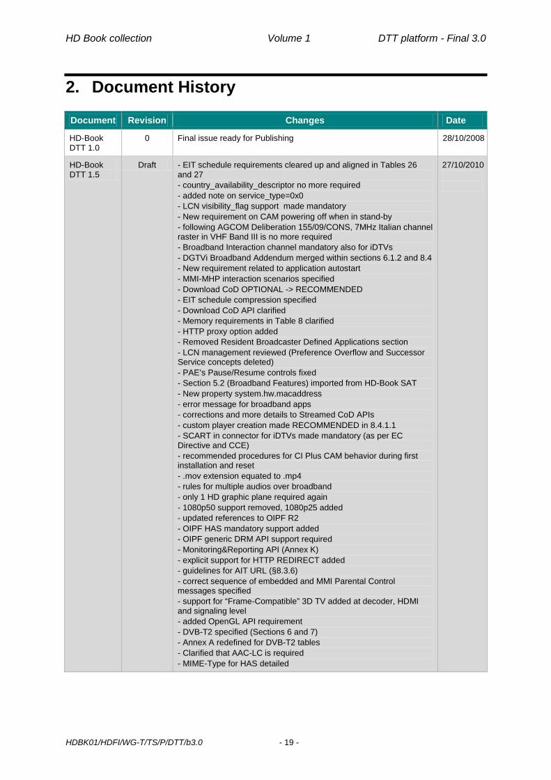
2. Document History Document Revision Changes Date
HD-Book DTT 1.0
0 Final issue ready for Publishing 28/10/2008
HD-Book DTT 1.5
Draft - EIT schedule requirements cleared up and aligned in Tables 26 and 27 - country_availability_descriptor no more required - added note on service_type=0x0 - LCN visibility_flag support made mandatory - New requirement on CAM powering off when in stand-by - following AGCOM Deliberation 155/09/CONS, 7MHz Italian channel raster in VHF Band III is no more required - Broadband Interaction channel mandatory also for iDTVs - DGTVi Broadband Addendum merged within sections 6.1.2 and 8.4 - New requirement related to application autostart - MMI-MHP interaction scenarios specified - Download CoD OPTIONAL -> RECOMMENDED - EIT schedule compression specified - Download CoD API clarified - Memory requirements in Table 8 clarified - HTTP proxy option added - Removed Resident Broadcaster Defined Applications section - LCN management reviewed (Preference Overflow and Successor Service concepts deleted) - PAE’s Pause/Resume controls fixed - Section 5.2 (Broadband Features) imported from HD-Book SAT - New property system.hw.macaddress - error message for broadband apps - corrections and more details to Streamed CoD APIs - custom player creation made RECOMMENDED in 8.4.1.1 - SCART in connector for iDTVs made mandatory (as per EC Directive and CCE) - recommended procedures for CI Plus CAM behavior during first installation and reset - .mov extension equated to .mp4 - rules for multiple audios over broadband - only 1 HD graphic plane required again - 1080p50 support removed, 1080p25 added - updated references to OIPF R2 - OIPF HAS mandatory support added - OIPF generic DRM API support required - Monitoring&Reporting API (Annex K) - explicit support for HTTP REDIRECT added - guidelines for AIT URL (§8.3.6) - correct sequence of embedded and MMI Parental Control messages specified - support for “Frame-Compatible” 3D TV added at decoder, HDMI and signaling level - added OpenGL API requirement - DVB-T2 specified (Sections 6 and 7) - Annex A redefined for DVB-T2 tables - Clarified that AAC-LC is required - MIME-Type for HAS detailed
27/10/2010
HD Book collection Volume 1 DTT platform - Final 3.0
HDBK01/HDFI/WG-T/TS/P/DTT/b3.0 - 20 -
Document Revision Changes Date
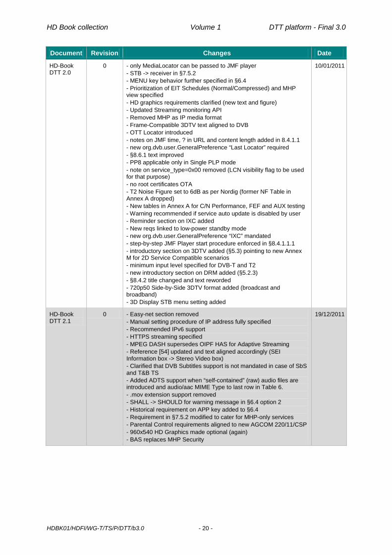
HD-Book DTT 2.0
0 - only MediaLocator can be passed to JMF player - STB -> receiver in §7.5.2 - MENU key behavior further specified in §6.4 - Prioritization of EIT Schedules (Normal/Compressed) and MHP view specified - HD graphics requirements clarified (new text and figure) - Updated Streaming monitoring API - Removed MHP as IP media format - Frame-Compatible 3DTV text aligned to DVB - OTT Locator introduced - notes on JMF time, ? in URL and content length added in 8.4.1.1 - new org.dvb.user.GeneralPreference “Last Locator” required - §8.6.1 text improved - PP8 applicable only in Single PLP mode - note on service_type=0x00 removed (LCN visibility flag to be used for that purpose) - no root certificates OTA - T2 Noise Figure set to 6dB as per Nordig (former NF Table in Annex A dropped) - New tables in Annex A for C/N Performance, FEF and AUX testing - Warning recommended if service auto update is disabled by user - Reminder section on IXC added - New reqs linked to low-power standby mode - new org.dvb.user.GeneralPreference “IXC” mandated - step-by-step JMF Player start procedure enforced in §8.4.1.1.1 - introductory section on 3DTV added (§5.3) pointing to new Annex M for 2D Service Compatible scenarios - minimum input level specified for DVB-T and T2 - new introductory section on DRM added (§5.2.3) - §8.4.2 title changed and text reworded - 720p50 Side-by-Side 3DTV format added (broadcast and broadband) - 3D Display STB menu setting added
10/01/2011
HD-Book DTT 2.1
0 - Easy-net section removed - Manual setting procedure of IP address fully specified - Recommended IPv6 support - HTTPS streaming specified - MPEG DASH supersedes OIPF HAS for Adaptive Streaming - Reference [54] updated and text aligned accordingly (SEI Information box -> Stereo Video box) - Clarified that DVB Subtitles support is not mandated in case of SbS and T&B TS - Added ADTS support when “self-contained” (raw) audio files are introduced and audio/aac MIME Type to last row in Table 6. - .mov extension support removed - SHALL -> SHOULD for warning message in §6.4 option 2 - Historical requirement on APP key added to §6.4 - Requirement in §7.5.2 modified to cater for MHP-only services - Parental Control requirements aligned to new AGCOM 220/11/CSP - 960x540 HD Graphics made optional (again) - BAS replaces MHP Security
19/12/2011

HD Book collection Volume 1 DTT platform - Final 3.0
HDBK01/HDFI/WG-T/TS/P/DTT/b3.0 - 21 -
Document Revision Changes Date
HD-Book DTT 2.1
1 - Clarified that LastLocator must refer only to conventional DVB services (no HTTPLocator or AIT file) - Clarified that HTTPLocator doesn’t apply to AIT file - Removed requirement on CI Plus Browser contrasting with CIplus C&RR - Optical connector made mandatory for SPDIF - Introduced optional HDMI ARC support - CI Plus reference updated to 1.3 - Clarifications and constraints on BAS certificate store added in §9.3.4.2 and §9.4.2 - Behavior in case of multiple <AdaptationSet> elements better specified - Reference to OIPF/DTG list of root certificates added in Table 3 - Annexes K and L now only reference GEM 1.3 (with clarification on MPEG-7 classification schemes) - Removed any reference to analogue tuner (optional by law since 1/1/2013) and channels - Enforcement for supporting at least 2 service contexts simultaneously active - Exposure of BAS white list requested (§9.4.4 and Annex P) - Linkage between RCMM and BAS white list made explicit - Clarifications on DASH live scenario (Dynamic MPD) added in Annex Q - Decoded PCM multichannel audio added to HDMI audio outputs with related system menu
30/09/2012
HD-Book DTT 2.2
0 - Provisions hard or impossible to be met removed in §7.3.4.5.3 (Service removal) - Automatic channel update (§7.6.5), previously only recommended, set as mandatory. Removed constraint “the receiver shall start the scanning procedure 1 hour after being put in standby mode”. Added clarifications on conflicts handling (pop-up timeout, stand-by case) - Table 34 added to clarify Application manager expected behavior - In case of multiple network interfaces (e.g. Ethernet and WiFi), system.hw.macaddress property shall expose the currently active one. - Clarified that In case of DASH contents, languages defined at MPD level must be taken into account for controls provided by org.davic.media.LanguageControl only if language information is missing at container level. - New section 9.3.5 dealing with impact of BAS on broadcast applications - Clarified in §9.3.4 that any GEM resource which is neither basic, nor system, nor private, shall be accessible by any BAS-compliant or non BAS-compliant application without the need of any PRF or certificate. - Option of certificates bound to one or more particular application introduced in §9.3.4 but left platform-dependent. - Sections A.2.1 and A.2.2 renamed - Ordering of representations returned by VideoStreamQualityInfo specified in Annex K

HD Book collection Volume 1 DTT platform - Final 3.0
HDBK01/HDFI/WG-T/TS/P/DTT/b3.0 - 22 -
Document Revision Changes Date
HD-Book DTT 2.3
0 - New sections 6.2.9 and 6.3.5, dealing with Player Pad added - Table 14 revised to include clarifications/requirements on certain keys’ behaviour during playback of broadband contents - Support for MPEG DASH MPEG2-TS Simple Profile removed. - Support for DVB-DASH Profile added. As a consequence previous profiling reqs in §6.1.2.1 have been marked as RECOMMENDED. - Support for EBU-TT-D Subtitles added in Table 4, §6.1.2.1 and §8.4.1.1.5 - iDTV SCART input and STB Output RF connectors downgraded to OPTIONAL - T2 reference updated to version 1.4.1 and reference to DIGITALEUROPE T2 white paper added - Updated rederence [8] to IEC 62216 - CAD support added (§6.1.2.1, §8.4.1.1, §8.4.1.1.5 and §8.4.1.2) for broadband parental control and playlists - T2 profile revised (PP8 support dropped, resistance to interference row added, NF revised and extended to multi tuner case, new C/N Performance table - Reference to CIPlus updated to version 1.3.1 - CICAM section (§9.1.3) extensively reviewed. - Historical Annex G dropped with still valid points moved to §9.1.3 - Historical Annexes C and D removed - Requirements for H.264/AVC broadcast and broadband profiles rewritten in terms of conformance points - HEVC support introduced:
- References [8][9] and [10] updated and [74] added - HEVC Main 10 Profile @ up to Level 4.1 support mandated for
broadcast and broadband profiles - HEVC Main 10 Profile @ up to Level 5.1 support recommended
for broadband profile on UHD receivers, with specific maximum bit rate values
- PSI and SI text added for HEVC in §7.2.2.2 and §7.2.5.1 - HEVC compatibility points added to Table 37 (CENC)
-
HD-Book DTT 2.4
0 - HEVC signalling in §7.2.5.1 aligned to final DVB version, specifying that service_type 0x01 is not allowed for HEVC services - Removed any reference to maximum bit rate for UHD contents streamed over HTTPS. - Added “UHD Receiver” definition in §4 - Same text as for SD -> HD graphics scaling added for SD/HD -> UHD graphics scaling in §8.3.5 - In order to maintain historical embedding of D-Book (SD) specs within HD-Book, MHP 1.0.3 and 1.1.3 are both mentioned and referenced - UHDTV DVB naming adopted instead of “UHD-1 Phase 1” - Delivery of EBU-TT-D subtitles as a separate document in a single file is not supported at this stage. - DIGITAL EUROPE HDMI/HDCP requirements for UHD receivers endorsed - Added notes in Table 1 on obsolesce of MPEG-1 L2 Audio and on EAC-3 embedding AC-3 - AC-3 removed from Table 5 and 37 - Added note in Table 5 on obsolesce of MPEG-1 L2 Audio - New references to Nordig, EBU and DIGITAL EUROPE documents on DVB-T/T2 front-end - DVB-T NF changed to 7dB (8dB for multiple tuners) - Minimum DVB-T input level updated with Annex C reused for new data - Table 1 rows on interference refined and extended to LTE case for both DVB-T and DVB-T2 - New note on FEF and Auxiliary Streams
-

HD Book collection Volume 1 DTT platform - Final 3.0
HDBK01/HDFI/WG-T/TS/P/DTT/b3.0 - 23 -
Document Revision Changes Date
- Handling of T2-Lite signal specified - Sections A.2 extensively revised with new tables on T2 C/N performance - Update of service name and LCN during automatic scan added in section 7.6.5 - Chapter 5 revised
HD-Book DTT 2.5
0 - Chapters 1 and 5 revised altogether
HD-Book DTT 3.0
0 - Forgotten “UHD-1 Phase 1” changed to “UHDTV” - References to HDMI 2.0 and HDCP 2.2 added for UHD receivers - SCART connector made OPTIONAL for UHD STB receivers - Clarifications on HDMI/HDCP output for UHD STBs added - Improved definition of “UHD Receiver” - Updated IEC references for RF connectors - 1080p50 set as new default HDMI output format for STBs - Section 1.1 revised and smoothed by HDFI Board
Credits: D-Book: Coordinator: M.Pellegrinato Editors: S.Vitale, E.Lambert, G.Venuti Contributors: G.Alberico, A.Bruno, G.Burzi, G.Gentile, E.Lambert, F.Lucidi,
E.O’Neill, C.Rosa, M.Visintin, D.Turi, R.Borroni, T.Tessarolo Translation: E.O’Neill HD-Book: Prj. Coordinator: M.Pellegrinato WorkGroup manager:
G.Alberico (formerly G.Ridolfi)
Editor: G.Venuti Joint HDFI/DGTVi/CRTV Experts Group:
D.Airola Gnota, V.Arrigoni, G.Asti, G.Ballocca, M.Bertolotti, A.Borgato, A.Bertella, R.Borroni, S.Bossi, S.Braghieri, G.Burzi, B.Buscema, P. Di Giacomo, D.Doldi, V.Drugeon, M.Frattolin, M.Fumagalli, M.Futagami M.Garganico, G.Gentile, D.Gibellino, A.Gioia, O.M.Grasso, F.Grilli, D.Hill-Jowett, I.Kain, M.Katri, V.Kostov, R.Iacoviello, A.Mapelli, V.Mignone, A.Morello, L.Noblet, M.Oriana, J.Outters, R.Paludo, B.Papini, N. Pawlowski, A.Pegoraro, A.Pettazzi, L.Piccarreta, F.Piolini, J.Rosenboom, S.Quesito, F.Rebucci, G.N.Resta, L.Rocchi, A.Roman, B.Sacco, G.Sammartano, S.Savage, L.Seccia, P.Sunna, M.Tabone, S.Trigila, M.Visintin, S.Waller, J.Wilson

Page intentionally left blank

HD Book collection Volume 1 DTT platform - Final 3.0
HDBK01/HDFI/WG-T/TS/P/DTT/b3.0 - 25 -
3. References For the purposes of this HD-Book, the following references apply:
[1] “Easy TV” Research Report, ITC 2003, and PsychNology Journal, 2003, Volume 1, Number 4, 355 – 377, “Helping Viewers Press the Right Buttons: Generating Intuitive Labels for Digital Terrestrial TV remote controls”, Jane Lessiter, Jonathan Freeman, Robert Davis and Andrew Dumbreck
[2] AGCOM Delibera n. 216/00/CONS: “Determinazione degli standard dei decodificatori e le norme per la ricezione dei programmi televisivi ad accesso condizionato”1
[3] CEI - Comitato Elettrotecnico Italiano, Comitato Tecnico 100, “Guida alla tecnologia e ai servizi dei ricevitori (Set Top Box e televisori digitali integrati) per la televisione digitale terrestre”, Progetto di Guida, 03/06/2003
[4] CENELEC EN 500 74 “Domestic and similar electronic equipment interconnection requirements: Peritelevision connector”
[5] Digital TV Group: “Baseline functional specification for DTT receivers for the UK” (D-Book)
[6] DVB BlueBook A016: “Digital Video Broadcasting (DVB); Interfaces for DVB Integrated Receiver Decoder (DVB-IRD)”
[7] EBU Recommendation R-110-2004 on “Subtitling on Digital TV Services
[8] IEC 62216:2009 “Digital terrestrial television receivers for the DVB-T system”
[9] ETSI TS 101 154 V1.12.1: Digital Video Broadcasting (DVB); Specification for the use of Video and Audio Coding in Broadcasting Applications based on the MPEG-2 Transport Stream
[10] ETSI EN 300 468 V1.15.1: “Digital Video Broadcasting (DVB); Specification for Service Information (SI) in DVB systems
[11] ETSI EN 300 472: Digital Video Broadcasting (DVB); Specification for conveying ITU-R System B Teletext in DVB bitstreams
[12] ETSI EN 300 706: Enhanced Teletext specification (analogue television)
[13] ETSI EN 300 744 V1.6.1 (2009-01): Digital Video Broadcasting (DVB); Framing structure, channel coding and modulation for digital terrestrial television
[14] ETSI EN 301 195: “Digital Video Broadcasting (DVB); Interaction channel through the Global System for Mobile communications (GSM)”
[15] ETSI EN 50221: “Common Interface Specification for Conditional Access and other Digital Video Broadcasting Decoder Applications”
[16] ETSI ES 202 130 V1.1.1 (2003-10): “Human Factors (HF); User Interfaces; Character repertoires, ordering rules and assignments to the 12-key telephone keypad”
[17] ETSI ES 202 218: “Digital Video Broadcasting (DVB); Interactive channel through the General Packet Radio System (GPRS)”
[18] ETSI ETS 300 743: “Digital Video Broadcasting (DVB); Subtitling systems”
[19] ETSI TR 101 162: “Digital Video Broadcasting (DVB); Allocation of Service Information (SI) codes for DVB systems”
1 A new deliberation meant to update Delibera n. 216/00/CONS, including also DVB-T2 requirements and a series of previous ancillary deliberations, should be published soon. A draft was sent out for public consultation at the end of 2013 inside Allegato B to Delibera n. 726/13/CONS

HD Book collection Volume 1 DTT platform - Final 3.0
HDBK01/HDFI/WG-T/TS/P/DTT/b3.0 - 26 -
[20] ETSI TR 101 211: “Digital Video Broadcasting (DVB); Guidelines on implementation and usage of Service Information (SI)”
[21] ETSI TR 102 308 V1.1.1 (2004-02):”User Group; User interoperability criteria”
[22] ETSI TS 201 812 V1.1.2: “Digital Video Broadcasting (DVB); Multimedia Home Platform (MHP) Specification 1.0.3”
[23] ETSI TS 102 006 1 V1.1.1 (2001-12): DVB Data Download Specification; Part 1: Simple Profile
[24] ETSI TS 102 006 V1.2.1 (2002-10): Specification for System Software Update in DVB Systems
[25] ETSI TS 102 812 v1.3.1: “Digital Video Broadcasting (DVB); Multimedia Home Platform (MHP) Specification 1.1.3”
[26] IEC 13818-1: “Information technology - Generic coding of moving pictures and associated audio information: systems”
[27] IEC 61937 Digital audio - Interface for non-linear PCM encoded audio bit streams applying IEC 60958
[28] DIGITALEUROPE: “White paper: Standardized DVB-T2 RF specifications” http://www.digitaleurope.org/Portals/0/Documents/TRPG/Broadcast/DIGITALEUROPE_White_Paper_DVB-T2_RF_27-04-2012.pdf
[29] IETF RFC 1334: “PPP Authentication Protocols”
[30] IETF RFC 1994: “PPP Challenge Handshake Authentication Protocol (CHAP)”
[31] ITU-R BT.653-2: “Teletext systems”
[32] AGCOM Delibera n. 155/09/CONS: “Integrazione della delibera 216/00/CON recante “Determinazione degli standard dei decodificatori e le norme per la ricezione dei programmi televisivi ad accesso condizionato” a seguito del nuovo piano nazionale di ripartizione delle frequenze”
[33] NorDig: “NorDig Unified Requirements for profiles Basic TV, Enhanced, Interactive and Internet for Digital Integrated Receiver Decoders and relevant parts of Integrated Digital TV sets”, ver 1.0
[34] Sun Microsystems Inc., “Security and Trust Services API for J2METM Specification”, June 1, 2004
[35] DTG Implementation and User Group, “Digital Receiver Implementation Guidelines and Recommended Receiver Reaction to Aspect Ratio Signalling in Digital Video Broadcasting”, Issue 1.2.1, Feb. 2001
[36] DGTVi D-Book, “Compatible DTTV receivers for the Italian market, September 2004
[37] CI Plus Forum LLP, “CI Plus Specification. Content Security Extensions to the Common Interface”, Version 1.3.1
[38] HDMI Licensing, LLC, “High-Definition Multimedia Interface”, rev.1.4a
[39] Digital Content Protection LLC, “High-Bandwidth Digital Content Protection System”, rev 1.3
[40] ETSI TS 102 757: “Digital Video Broadcasting (DVB); Content Purchasing API
[41] C.Poynton, “Digital Video and HDTV. Algorithms and Interfaces”, Morgan Kaufmann Publishers
[42] ISO/IEC 14496-14: “Coding of audio-visual objects -- Part 14: MP4 file format”
[43] Open IPTV Forum Release 2 Version 2.3 specification, “Volume 2: Media Formats”, January 2014, http://www.oipf.tv/specifications
[44] IETF, RFC 2616, “Hypertext Transfer Protocol – HTTP/1.1”, < http://www.rfc-editor.org/rfc/rfc2616.txt>
[45] Open IPTV Forum Release 2 Version 2.3 specification, “Volume 4: Protocols”, January 2014, http://www.oipf.tv/specifications

HD Book collection Volume 1 DTT platform - Final 3.0
HDBK01/HDFI/WG-T/TS/P/DTT/b3.0 - 27 -
[46] Open IPTV Forum Release 2 Version 2.1 specification, “Volume 6: Procedural Application Environment”, January 2014, http://www.oipf.tv/specifications
[47] ETSI EN 302 755 V1.4.1: Framing structure, channel coding and modulation for a second generation digital terrestrial television broadcasting system
[48] ETSI TS 102 831 V1.2.1 (2012/01): Implementation guidelines for a second generation digital terrestrial television broadcasting system (DVB-T2)
[49] IETF, RFC 1950, “ZLIB Compressed Data Format Specification version 3.3”, http://www.rfc-editor.org/rfc/rfc1950.txt>
[50] IETF, RFC 1951, “DEFLATE Compressed Data Format Specification version 1.3”, http://www.rfc-editor.org/rfc/rfc1951.txt
[51] DGTVi Broadband Addendum, “Compatible High Definition receivers for the Italian market: special requirements for broadband media delivery”, October 2009
[52] USB Implementers Forum, Inc. “Universal Serial Bus Specification Revision 2.0”, April 2000
[53] HDMI Licensing, LLC, “High-Definition Multimedia Interface – Specification Version 1.4a – Extraction of 3D Signalling Portion”, March 2010
[54] ISO/IEC 14496-12:2008 | 15444-12:2008 (3rd edition) / Amendment 2: “Support for sub-track selection & switching, post-decoder requirements, and colour information”, December 2011
[55] JSR 239: “Java™ Binding for the OpenGL® ES API, August 2007
[56] NorDig: “Requirements to NorDig-T2 compliant IRDs - Addendum to the NorDig Unified Requirements (ver 2.1) for Integrated Receiver Decoders for use in cable, satellite, terrestrial and IP-based networks” (ver 1.0.1)
[57] ETSI TS 101 547: “Frame Compatible Plano-stereoscopic 3DTV”, January 2011
[58] ITU-T Recommendation H.264 / ISO/IEC 14496-10:2010: “Information technology -- Coding of audio-visual objects -- Part 10: Advanced Video Coding”
[59] ISO/IEC 23001-7: Information technology – Common encryption in ISO base media file format files
[60] ISO/IEC 23009-1: Information technology – Dynamic adaptive streaming over HTTP (DASH), Part 1: Media presentation description and segment formats
[61] ISO/IEC 14496-12: Information technology – Coding of audio-visual objects – Part 12: ISO base media file format
[62] ETSI, TS 102 728 v1.2.1: “Digital Video Broadcasting (DVB); Globally Executable MHP (GEM) Specification 1.3 (including OTT and hybrid broadcast/broadband)”, September 2011
[63] IETF, RFC 2818, “HTTP Over TLS”, http://www.ietf.org/rfc/rfc2818.txt
[64] IETF, RFC 2459, Internet X.509 Public Key Infrastructure Certificate and CRL Profile, http://www.ietf.org/rfc/rfc2459.txt
[65] IETF, RFC 2560, X.509 Internet Public Key Infrastructure Online Certificate Status Protocol – OCSP, http://www.ietf.org/rfc/rfc2560.txt
[66] AGCOM Delibera n. 220/11/CSP: “Regolamento in materia di accorgimenti tecnici da adottare per l’esclusione della visione e dell’ascolto da parte dei minori di film ai quali sia stato negato il nulla osta per la proiezione o la rappresentazione in pubblico, di film vietati ai minori di diciotto anni e di programmi classificabili a visione per soli adulti ai sensi dell’articolo 34, commi 5 e 11, del Testo unico dei servizi di media audiovisivi e radiofonici” http://www.agcom.it/default.aspx?DocID=6866
[67] ISO/IEC 14496-3: “Coding of audio-visual objects -- Part 3: Audio”

HD Book collection Volume 1 DTT platform - Final 3.0
HDBK01/HDFI/WG-T/TS/P/DTT/b3.0 - 28 -
[68] Open IPTV Forum: “List of recommended TLS root certificates”, http://www.oipf.tv/images/site/DOCS/oipf-il-dae-693-tls_root_certificate_list.xls
[69] ETSI TS 103 285: “Digital Video Broadcasting (DVB); MPEG-DASH Profile for Transport of ISOBMFF Based DVB Services over IP Based Networks”, February 2014
[70] EBU, EBU TECH 3380 - EBU-TT-D Subtitling Distribution Format, Version 1.0, January 2014, https://tech.ebu.ch/docs/tech/tech3380.pdf
[71] EBU, EBU TECH 3381- Carriage of EBU-TT-D in ISOBMFF, Draft for comments, January 2014, https://tech.ebu.ch/docs/tech/tech3381.pdf
[72] ISO/IEC FDIS 14496-30 Information technology - Coding of audio-visual objects - Part 30: Timed text and other visual overlays in ISO base media file format
[73] Open IPTV Forum Release 2 Version 2.3 specification, “Volume 5: Declarative Application Environment”, January 2014, http://www.oipf.tv/specifications
[74] ITU-R Recommendation BT.2020-1: "Parameter values for ultra-high definition television systems for production and international programme exchange"
[75] ETSI TS 102 992 v1.1.1 (2010-09): “Digital Video Broadcasting (DVB); Structure and modulation of optional transmitter signatures (T2-TX-SIG) for use with the DVB-T2 second generation digital terrestrial television broadcasting system”
[76] EBU, EBU TECH 3348 – Frequency and Network planning aspects of DVB-T2, version 3.0 , November 2013, https://tech.ebu.ch/docs/tech/tech3348.pdf
[77] NorDig “Unified Test Plan for Integrated Receiver Decoders for use in cable, satellite, terrestrial and IP-based networks”, ver 2.4, October 2013, http://www.nordig.org/pdf/NorDig-Unified_Test_plan_ver_2.4.pdf
[78] NorDig: “Unified Requirements for IRDs for use in cable, satellite, terrestrial and IP based network”, version 2.5.1, August 2014, http://www.nordig.org/pdf/NorDig-Unified_ver_2.5.1.pdf
[79] HDMI Licensing, LLC, “High-Definition Multimedia Interface”, rev.2.0
[80] Digital Content Protection LLC, “High-Bandwidth Digital Content Protection System”, rev 2.2
[81] ITU-R Recommendation BT.709-5: " Parameter values for the HDTV standards for production and international programme exchange "
[82] IEC 61169-2:2007 “Radio-frequency connectors - Part 2: Sectional specification. Radio frequency coaxial connectors of type 9,52”

HD Book collection Volume 1 DTT platform - Final 3.0
HDBK01/HDFI/WG-T/TS/P/DTT/b3.0 - 29 -
4. Definitions and abbreviations 4.1. Definitions
3DTV “Frame-Compatible” Mode: a frame-compatible 3DTV format is one that carries separate left and right video signals within the video frame used to convey a conventional 2D high-definition signal by squeezing them to fit within the space of one picture.
3DTV “Service-Compatible” Mode: in service-compatible 3DTV transmissions a regular 2D high definition signal is broadcasted to all viewers, while additional data are sent to complete the picture for those homes with a 3D display.
Adaptive Streaming: a technique, used in the context of OTTV to cope with Open Internet varying throughput conditions, where more files corresponding to encodings at different bit rates of the same content which the receiver can seamlessly switch to are made available by the Service Provider.
Application Service Provider: an entity that manages and distributes applications and services for interactive television to customers (i.e. broadcasters and consumers) from a central data center. This entity may also provide interaction channel processing services.
Bound Application: A MHP application that is linked to another service and that is meant to be accessed only after tuning in to the other service.
Cross carriage: Carrying the data (typically EIT data) pertaining to one multiplex on a different multiplex. Cross carriage agreements usually imply reciprocity.
Domain of an Application: The domain of an Xlet characterizes the "space" within which the Xlet is able to execute. This includes both the "connection" where the Xlet is delivered and other "connections" where an already executing Xlet is allowed to continue executing. An application cannot run outside its domain. The maximum lifetime of an application extends from the moment the user navigates to its domain until the moment that the user navigates away from its domain. In the broadcast case a "connection" corresponds to a DVB-service. Broadcast signalling indicates which services can load an application and which services allow an already active application to continue.
Independent Application: A MHP service which is meant to be directly accessed by the end user (e.g. through a Channel number). An Independent Application may have bound applications linked to it. EPGs are an example of independent application. Also called Non Bound Application
Interaction Channel: a bi-directional link connecting the Receiver to a Server for providing extra functionality, such as personalized data, billing, e-commerce, etc. Often called return channel.
License: An object that governs the use of Content and specifies the conditions for allowing access to the Content Key used to encrypt the Content.
Locator: The unique identifier of a DVB service/event. Out of Box Experience: the first contact of the user with the product, as experienced when
taking it out of the packaging box and plugging it into the wall socket and antenna cable (without having to read tons of manuals…).
Over-The-Top Services: A general term for video services delivered over the Open Internet. It's referred to as "over-the-top" because these services ride on top of plain Internet access service and don't require any business or technology affiliations with the network operator.
Privileged application: A privileged application is an application which can legitimately access a certain resource according to the BAS model. A not privileged application is an application which does not satisfy the policies enforced by the BAS model to grant access to that resource.

HD Book collection Volume 1 DTT platform - Final 3.0
HDBK01/HDFI/WG-T/TS/P/DTT/b3.0 - 30 -
Receiver: a piece of equipment designed to receive (and decode) DTTV signal. It can be provided as a separate box – in this case it is often called Set Top Box (STB), and sometimes Integrated Receiver Decoder (IRD) – or can be incorporated into a TV set, which is then called an Integrated Digital TV set (iDTV).
Service: For TV and Radio, a sequence of programmes under the control of a broadcaster which can be broadcast as part of a schedule [10]. For Applications and Data, refers to a data stream in the MHP that can be used directly or be presented to an output interface, without having to tune into a TV or Radio service.
Service List: List of all autonomously accessible services (television, radio, application, and data) identified through a service number
Plano-stereoscopic TV: First Generation 3DTV systems are sometimes called ‘Plano-stereoscopic TV’ because the underlying characteristic of these systems is that they carry two channels, for viewing by the left and right eye (L and R). These systems usually require the viewer to wear glasses for large screen viewing.
T-Government Services: services of e-government provided on digital television receivers. Those services in many cases require the use of an interaction channel, and of a smart card (“citizen’s card”, e-ID card, etc.)
TV Viewing Mode or Viewing Mode: normal TV viewing condition, when less than 5% of the screen area is covered by any MHP, or receiver proprietary, GUI.
UHD Receiver: either a TV set with UHD resolution capable of decoding UHD signals specified in this document and used as receiver or a STB capable of decoding UHD signals specified in this document and of driving a display with UHD resolution.
4.2. Abbreviations 3DTV Plano-stereoscopic 3D TV AAC Advanced Audio Coding AAC-LC AAC Low Complexity AC-3 Audio Coding 3 ACE Active Constellation Extension ADSL Asymmetric Digital Subscriber Line ADTS Audio Data Transport Stream AES Advanced Encryption Standard AFD Active Format Descriptor AGCOM Autorità per le Garanzie nelle Comunicazioni AIT Application Information Table API Application Programming Interface AVC Advanced Video Coding BAS Broadband Application Security BAT Bouquet Association Table BER Bit Error Rate BW Band Width CA Certification Authority CA Conditional Access CAD Content Access Descriptor CAM Conditional Access Module CENC Common Encryption CHAP Challenge Handshake Authentication Protocol CI DVB Common Interface CICAM CI CAM CoD Content on Demand COFDM Coded Orthogonal Frequency Division Multiplexing CRL Certificate Revocation List CRTV Confindustria Radio TV CVBS Component Video Baseband Signal

HD Book collection Volume 1 DTT platform - Final 3.0
HDBK01/HDFI/WG-T/TS/P/DTT/b3.0 - 31 -
DAB Digital Audio Broadcasting DAE Declarative Application Environment DASH Dynamic Adaptive Streaming over HTTP DHCP Dynamic Host Configuration Protocol DRM Digital Rights Management DTS Digital Theater Systems DTTV Digital Terrestrial Television DTV Digital Television DVB Digital Video Broadcasting DVB-H DVB Handheld DVB-T DVB Terrestrial EACEM European Association of Consumer Electronics Manufacturer EDID Extended Display Identification Data EHDF European HD Forum EICTA European Information and Communication Technology Association EIT Event Information Table EPG Electronic Program Guide ETSI European Telecommunications Standards Institute EU European Union FEF Future Extension Frame FIFO First In First Out FFT Fast Fourier Transform FTTH Fiber To The Home GEM Globally Executable MHP GPRS General Packet Radio System GS Generic Stream GUI Graphic User Interface HD High Definition HDCP High bandwidth Digital Copy Protection HDFI HD Forum Italia HDMI High Definition Multimedia Interface HDSPA High-Speed Downlink Packet Access HDTV High Definition TV HE-AAC High Efficiency AAC HEVC High Efficiency Video Coding HTTP Hyper-Text Transfer Protocol HTTPS Hyper-Text Transfer Protocol Secure iDTV Integrated Digital TV Set IP Internet Protocol IPTV IP Television IRD Integrated Receiver Decoder ISO International Organization for Standardization ISOBMFF ISO Base Media File Format ISP Internet Service Provider IXC Inter-Xlet Communication i-TV Interactive Television JMF Java Media Framework LAN Local Access Network LTE Long Term Evolution MFN Multi Frequency Network MHP Multimedia Home Platform MIME Multipurpose Internet Mail Extensions MPD Media Presentation Description MPEG Moving Picture Experts Group MUG MHP Umbrella Group

HD Book collection Volume 1 DTT platform - Final 3.0
HDBK01/HDFI/WG-T/TS/P/DTT/b3.0 - 32 -
NID Network ID NIT Network Information Table NTS Network Time-Shift OCSP Online Certificate Status Protocol OFDM Orthogonal Frequency Division Multiplexing OIPF Open IPTV Forum OMA Open Mobile Alliance ONID Original Network ID OSD On-Screen Display OTA Over The Air OTT-TV Over The Top TV PAE Procedural Application Environment PAL Phase Alternate Lock PAP PPP Authentication Protocol PAPR Peak-to-Average Power Ratio PAT Program Association Table PCMCIA Personal Computer Memory Card International Association PDC Program Delivery Control PID Packet IDentifier PKI Public Key Infrastructure PLP Physical Layer Pipe PMT Program Map Table POP Point Of Presence PPP Point-to-Point Protocol PPPoE PPP over Ethernet PRF Permission Request File PSI Program Specific Information PSTN Public Switched Telephone Network QAM Quadrature Amplitude Modulation QEF Quasi Error-Free QPSK Quadrature Phase Shift Keying RCMM Root Certificate Management Message RRC Regional Radio Conference RSA Rivest, Shamir, Adleman SATSA Security And Trust Services API SCART Syndicat des Constructeurs d'Appareils Radiorécepteurs et Téléviseurs SD Standard Definition SDT Service Description Table SEI Supplemental Enhancement Information SFN Single Frequency Network SI Service Information SID Service ID SIM Security Identity Module SSU System Software Update STB Set Top Box T-DMB Terrestrial Digital Media Broadcasting T2-IRD DVB-T2 Integrated Receiver Decoder TLS Transport Layer Security TM DVB Technical Module TFS Time Frequency Slicing TR Tone Reservation TS Transport Stream TSID Transport Stream ID UHD(TV) Ultra High Definition (TV) UHF Ultra High Frequency
HD Book collection Volume 1 DTT platform - Final 3.0
HDBK01/HDFI/WG-T/TS/P/DTT/b3.0 - 33 -
UI User Interface UNT Update Notification Table URL Uniform Resource Locator USB Universal Serial Bus VHF Very High Frequency WAN Wide-area Access Network WLAN Wireless LAN WSS Wide-Screen Signalling

Page intentionally left blank

HD Book collection Volume 1 DTT platform - Final 3.0
HDBK01/HDFI/WG-T/TS/P/DTT/b3.0 - 35 -
5. The HD-Books HD-Books are a collection of technical specifications aimed to manufacturers of television receivers (STB and TV). It sets out the baseline requirements for the Italian digital television platform: open, horizontal, interoperable, hybrid. The HD-Book Collection, born in 2008, consists of specific HD-Book volumes, dedicated to the different distribution platforms: DTT (Digital Terrestrial Television), SAT (Open Satellite) and OTT (Over the Top). The HD-Book Collection is published by HD Forum Italia, in collaboration with the other stakeholders of the Italian digital television platform: CRTV (Confindustria Radio Televisioni) and Tivùsat. HD Forum Italia (HDFI) is an association constituted on September 19th. 2006, to represent the general interests of the industry and consumers towards high definition. HDFI is aimed to promote, support, illustrate and disseminate the utilization of multimedia contents and audiovisual programmes, productions and technology in high definition format (HD) and beyond (3DTV, UHDTV). The HDFI association members represent the major institution & companies in the audiovisual & telecommunication Industry in Italy. They cover most segments of the entire production chain, from the content creations to end users: Aeranti Corallo, Dolby, Eutelsat, Fastweb, Fondazione Ugo Bordoni, Fracarro, LG, Mediaset, Panasonic, RAI, Samsung, SES Astra, Sisvel Technology, Sky Italia, Sony, STMicroelectronics, Telecom Italia, Telecom Italia Media, TP Vision and Vestel. HDFI adheres, as Italian member organization, to FAME (Forum on Advanced Media in Europe, formerly known as EHDF, European HD Forum), promoted and jointly chaired by the international organizations EBU (European Broadcasting Union) and DIF (Digital Interoperability Forum. DGTVi has been the association which has represented the general interests of the Italian DTT industry until ASO completion on June 2012. Since June 2013 DGTVi role has been taken over and widened in scope by Confindustria Radio Televisioni (CRTV) which now represents the general interests of the whole Italian broadcasting industry (TV, Radio, DTT, SAT). This document describes the baseline requirements that are needed for a HDTV DTT receiver with broadband connectivity to claim compatibility with joint HDFI/CRTV specifications. The first baseline specification was finalized by DGTVi in September 2004 under the name of “D-Book, Compatible DTTV receivers for the Italian market” (v1.0). This specification was later updated with different stand-alone addenda. The “D-Book 1.2” merged all these addenda in a single clean document which took into account the comments received by the industry. The D-Book 1.2 has been the basis on which HD-Book DTT 1.0 was jointly developed in 2008 by HDFI and CRTV, by introducing all HD-specific features (formats, codecs, connectors, signalling, simulcasting). At the same time, latest developments in the areas of supplementary audio and of automatic channel ordering (LCN) to cope with cross-border conflicts were taken into account. Such developments were then incorporated in D-Book 1.3. Besides applying all the necessary corrigenda to HD-Book DTT 1.0, its 2.0 successor merged the so-called “Broadband Addendum” which had been developed by DGTVi in the second half of 2009, after HD-Book DTT 1.0 was published, to complement it in the area of media delivery over broadband (IP) lines.
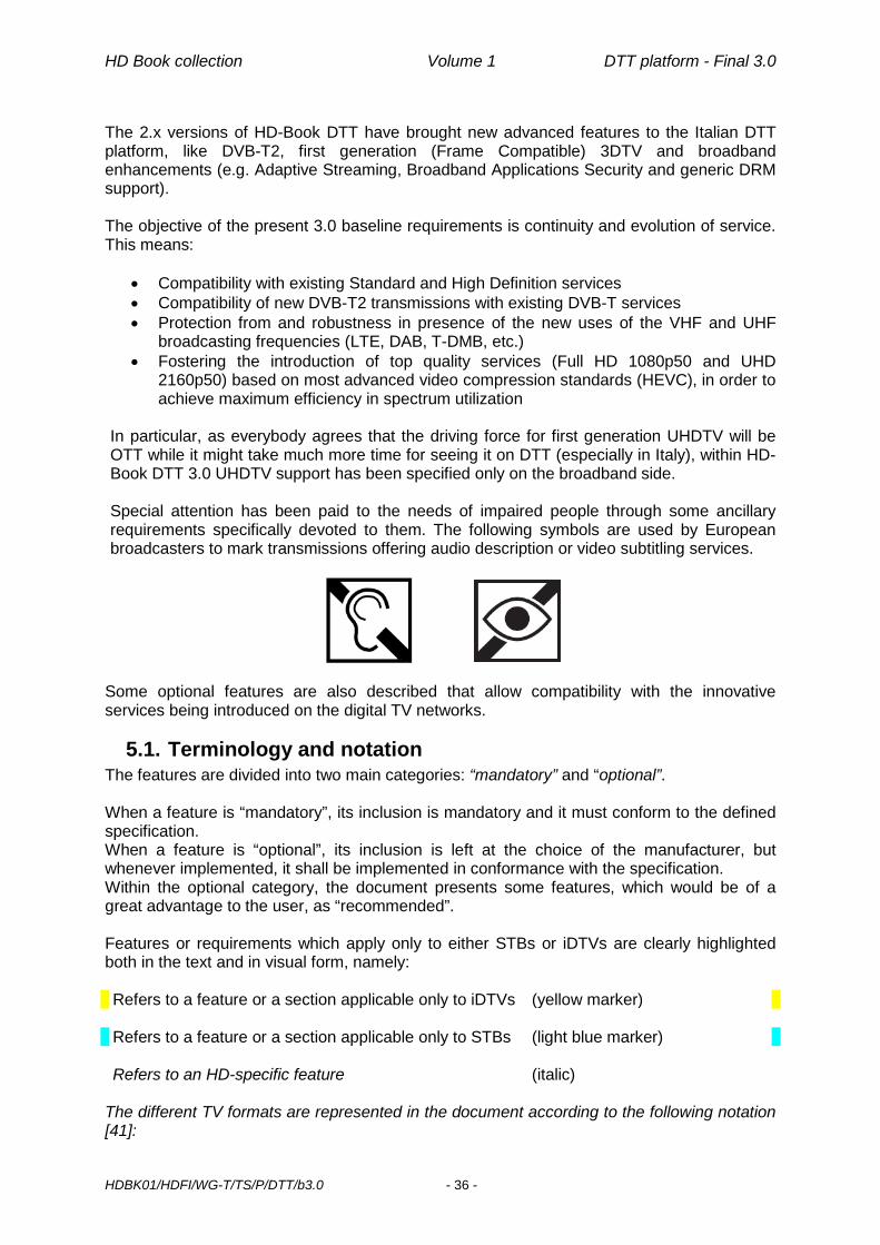
HD Book collection Volume 1 DTT platform - Final 3.0
HDBK01/HDFI/WG-T/TS/P/DTT/b3.0 - 36 -
The 2.x versions of HD-Book DTT have brought new advanced features to the Italian DTT platform, like DVB-T2, first generation (Frame Compatible) 3DTV and broadband enhancements (e.g. Adaptive Streaming, Broadband Applications Security and generic DRM support). The objective of the present 3.0 baseline requirements is continuity and evolution of service. This means:
• Compatibility with existing Standard and High Definition services • Compatibility of new DVB-T2 transmissions with existing DVB-T services • Protection from and robustness in presence of the new uses of the VHF and UHF
broadcasting frequencies (LTE, DAB, T-DMB, etc.) • Fostering the introduction of top quality services (Full HD 1080p50 and UHD
2160p50) based on most advanced video compression standards (HEVC), in order to achieve maximum efficiency in spectrum utilization
In particular, as everybody agrees that the driving force for first generation UHDTV will be OTT while it might take much more time for seeing it on DTT (especially in Italy), within HD-Book DTT 3.0 UHDTV support has been specified only on the broadband side. Special attention has been paid to the needs of impaired people through some ancillary requirements specifically devoted to them. The following symbols are used by European broadcasters to mark transmissions offering audio description or video subtitling services.
Some optional features are also described that allow compatibility with the innovative services being introduced on the digital TV networks.
5.1. Terminology and notation The features are divided into two main categories: “mandatory” and “optional”. When a feature is “mandatory”, its inclusion is mandatory and it must conform to the defined specification. When a feature is “optional”, its inclusion is left at the choice of the manufacturer, but whenever implemented, it shall be implemented in conformance with the specification. Within the optional category, the document presents some features, which would be of a great advantage to the user, as “recommended”. Features or requirements which apply only to either STBs or iDTVs are clearly highlighted both in the text and in visual form, namely: Refers to a feature or a section applicable only to iDTVs (yellow marker) Refers to a feature or a section applicable only to STBs (light blue marker) Refers to an HD-specific feature (italic)
The different TV formats are represented in the document according to the following notation [41]:

HD Book collection Volume 1 DTT platform - Final 3.0
HDBK01/HDFI/WG-T/TS/P/DTT/b3.0 - 37 -
<active lines> <scanning> <frames/s> For instance:
576i25 (aka 576@50i) represents the 720x576 interlaced format in 50Hz systems 720p50 (aka 720@50p) represents the 1280x720 progressive format in 50Hz systems 1080i25 (aka 1080@50i) represents the 1920x1080 interlaced format in 50Hz systems
5.2. Broadband Features Since version 2.0 the HD-Book DTT fully includes the so-called “Broadband Addendum” [51] specification, which was issued by DGTVi as a separate document on October 2009, mainly based on Open IPTV Forum specifications [43][45][46]. The aim of the Broadband Addendum was to complement HD Book DTT 1.0 specification in the area of media delivery, mostly on-demand but not necessarily restricted to, over broadband lines. In fact whilst usage of MHP interaction channel of the broadband port herein required had been fully specified, no clear provision had been made for accessing media contents over broadband (IP) lines. In the scope of this document “broadband (IP) lines” are best-effort internet connections offered by ISPs. In other words, the services enabled by the specification included don’t strictly require a connection to the (managed) network of an IPTV Service Provider. HD-Book DTT 2.1 has progressed Broadband Addendum specifications by addressing also adaptive streaming and, to a minimum extent, broadband content and service protection. HD-Book DTT 3.0 makes one further step forward in this area by:
• aligning adaptive streaming specs to a widely supported profile (DVB-DASH) [69] • introducing HEVC support, based on DVB profiling [9] • opening the door to first generation UHD OTT services, as defined by DVB [9]
Although the compatible receiver herein specified is provided with 2 different interoperable but independent front-ends, (broadcast DTT tuner and broadband IP port), both capable of supporting media Contents Delivery Services, the adjective “Hybrid” does not apply to this document. In fact core Broadcast-centric services, essentially treated in this HD-Book, are considered as prevalent with respect to other ancillary delivery services (OTT-TV CoD or NTS2) made available by broadband lines connectivity defined in this specification.
5.2.1. Broadband content and service protection Whilst DGTVi Broadband Addendum didn’t mention anything related to broadband content and service protection, HD-Book DTT 2.1 has provided a minimum level of interoperability for applications in this area by specifying 2 generic DRM components, where generic means not tied to any particular DRM system:
• a generic DRM API (§8.4.1.3) • a common encryption method for MP4 container (§9.2).
In fact, as done so far for CA systems, adoption of one or more specific DRM systems is outside the scope of CRTV/HDFI’s documents and it’s left up to interested operators and manufacturers instead.
2 OTT-TV Over the Top TV; CoD Content on demand; NTS: Network Time Shift

HD Book collection Volume 1 DTT platform - Final 3.0
HDBK01/HDFI/WG-T/TS/P/DTT/b3.0 - 38 -
5.2.2. Broadband Application Security A novel framework, named Broadband Application Security (BAS), has been introduced in HD-Book DTT 2.1 for securing broadband applications.
5.3. 3DTV Features Another new key area addressed since HD-Book DTT 2.0 is the so-called “Frame-Compatible Plano-stereoscopic 3DTV” [57]. A frame-compatible 3DTV format is one that carries separate left and right video signals within the video frame used to convey a conventional 2D high-definition signal by squeezing them to fit within the space of one picture. DVB standards on 3DTV formats and signalling have been endorsed since HD-Book DTT 2.0, including provisions for some degree of 2D service compatibility (see Annex M).
5.4. Linkage with other organizations Where available and compatible with the Italian situation, the specification contained in this document refers to standards developed by standards setting organisations (DVB, ETSI, DIGITALEUROPE, NorDig, MPEG, OIPF, ISO, CEI, CEN). Furthermore, it follows the Italian legislation in force concerning DTTV and reception equipment for Digital Terrestrial Television3. For the aspects of the receiver where nothing is indicated, the expectation is that manufacturers will follow the EICTA E-book. The version 2.0 is taken as a reference (with the exception of obvious editorial errors). However, the HD-Book DTT does not endorse the E-Book specifications concerning the transmitted signal (which principally concerns networks operators and not receiver manufacturers) and expects that receivers shall be compatible with all DVB legal configurations and signalling. This is to great extent due to the fact that the E-Book is not adapted to the specific structure of digital terrestrial broadcasting in Italy.
5.5. Graceful Degradation A receiver compliant with this specification shall implement a “graceful degradation” mechanism for specific unsupported (optional) features and shall behave as follows:
• the receiver shall not unexpectedly terminate the current runtime application • the receiver shall not hang up • the user shall be unaware of any exception thrown by the middleware (for
applications conforming to the MHP specification), but shall be informed of the unavailability of the requested service or functionality on the receiver.
3 Specifically the Italian Communication Authority Deliberation n° 216/00/CONS

HD Book collection Volume 1 DTT platform - Final 3.0
HDBK01/HDFI/WG-T/TS/P/DTT/b3.0 - 39 -
6. Basic requirements 6.1. Hardware requirements for the receiver
The Italian DTT network is still evolving. Receivers must support a range of transmission parameters and modes to allow for changes in the use of the allocated spectrum. Receivers MUST meet minimum performance criteria to maximise both network coverage and the reliability of receivers acquired by consumers in the retail market.
6.1.1. Terrestrial Front End & Signal Decoding The receiver SHALL support the signal characteristics specified in the following. A receiver capable of receiving DVB-T2 broadcasts [47] SHALL also be capable of receiving DVB-T broadcasts [13]. Such a receiver is in the following referred to as “T2-IRD”, when there is a need to differentiate such a receiver from a receiver supporting DVB-T only. The T2-IRD shall automatically detect whether DVB-T or DVB-T2 signal is being used in the specific channel.
6.1.1.1. Mandatory features Feature Specification Comment DVB-T
Channel Bandwidth - 7 MHz in Band III (European VHF channel allocation) - 8 MHz in Band IV-V (UHF)
Ref. : [2] Since July 2009, according to resolutions taken at Regional Radio Conference GE06, Italy has adopted 7MHz bandwidth in Band III with European channel allocation [32]
Digital demodulation COFDM DVB-T (EN 300 744) Ref. : [2]
Transmission mode 2k and 8k Ref.: [2]
Constellation Combinations QPSK, 16-QAM, 64-QAM, hierarchical 16-QAM, hierarchical 64-QAM)
Ref.: [2]
Code rates 1/2, 2/3,3/4, 5/6 or 7/8 Ref.: [2]
Guard Interval 1/4, 1/8, 1/16 or 1/32 Ref.: [2]
Hierarchical Modulation Alpha=1, 2 or 4 (where applicable) The receiver is required to demodulate and present all and only the services that it is able to handle among those possibly available in both high (HP) and low priority (LP) streams. Ref.: [13]
Noise Figure (NF) Better than 7 dB Note: for dual or multiple internal tuners a NF better than 8 dB is highly recommended for implementation.
Ref.: [56] [28] Same as §12.7.3 in E-Book [8]. 1 dB better than in [2].
Implementation Margin Better than 3 dB. Ref.: [2]

HD Book collection Volume 1 DTT platform - Final 3.0
HDBK01/HDFI/WG-T/TS/P/DTT/b3.0 - 40 -
Feature Specification Comment Minimum signal level The demodulator operates on Gaussian
channel at QEF performance (i.e. BER less than 2x10⁻⁴ after convolutional decoding and before Reed-Solomon decoding) with a minimum input signal of -78.2dBm across the whole UHF range (8k, 64 QAM mode, 2/3 code rate, Tg/Tu ¼, 8dB NF and 7.61MHz bandwidth).
Ref.: [2] [77], [78]. See Annex C, The value -78.2 dBm is the value mandated in [2], under the main hypothesis of NF=8 dB.
Maximum Signal Level Greater than -28 dBm (80 dBμV on 75 Ohm) without degrading the signal (Implementation Margin).
Even with a strong reduction in the power transmitted, in the hypothesis of an antenna gain of 12 dB and a cable loss of 4 dB there could be levels reaching the receiver of -35dBm (73 dBμV on 75 ohm) and of the order of -25, -30 dBm. The deliberation of AGCOM reports: “The front end must operate with an over-specified Implementation Margin (note of the editor: equivalent to 3dB) with maximum signal of -35dBm.” Ref.: [2]
Resistance to interference (analogue and digital) co-channel, on adjacent channel and from LTE signals in 800 MHz Band.
Reference values on resistance to interference (analogue and digital) from other channels are contained in Allegato A #1.m of AGCOM deliberation 216/00/CONS [2] Reference on resistance to interference from LTE signals in 800 MHz Band is the NorDig Unified ver. 2.5.1, chapter 3.4.10.6.2 “Immunity to 800 MHz LTE signals in other channels” [78].
It’s expected that the DVB-T receiver permits an interfering DVB-T/T2 signal with (minimum) interference to signal level ratio (I/C) of 38 dB when the interference is on +/-2 channels (Band IV and V UHF, 8MHz BW), while maintaining QEF reception for DVB-T modes 64QAM, GI 1/4, code 2/3 and 3/4. See also [78], paragraph 3.4.10.6.1 and Table 3.16.
Behaviour in the presence of two static (distant) echoes
The receiver correctly operates in the presence of two static echoes (i.e. 2 paths) with a relative delay in a range of 0,2 µs. and 0,9 times the duration of the guard interval, independently of the value of the amplitude and of the relative phases. This requirement applies to all possible modes.
This is the minimum requirement if one wants the receiver to also operate in a Single Frequency Network as well. The minimum performance and test profile are those presented in E-Book [8], §12.7.8.1
Behaviour in the presence of short echoes
In the presence of echoes of matching levels, the demodulator operates with an implementation margin of 3.5 dB when the channel profile corresponds to that reported in EN 300 744 [13] (Rice and Rayleigh profiles using the six strongest rays). In the presence of an echo at 0 dB, in the absence of noise, to the limit of the guard interval, and for any guard interval, the demodulator operates with QEF performance in the 64 QAM mode and with 2/3 code rate.
Ref: [13] [2] The minimum performance and test profile are those presented in E-Book [8], §12.7.8.2
Change of modulation parameters
At least code rate, time guard and constellation changes shall be automatically detected
Network(s) evolution shouldn’t impact existing services
Demultiplexing MPEG-2 System Transport Stream Ref.: [9]

HD Book collection Volume 1 DTT platform - Final 3.0
HDBK01/HDFI/WG-T/TS/P/DTT/b3.0 - 41 -
Feature Specification Comment DVB-T2
Channel Bandwidth
- 1.7 MHz (OPTIONAL) - 7 MHz (European VHF channel
allocation) in Band III - 8 MHz in Band IV-V (UHF)
Since July 2009, according to resolutions taken at Regional Radio Conference GE06, Italy has adopted 7MHz bandwidth in Band III with European cannel allocation [32]
Digital demodulation COFDM DVB-T2 Ref. : [47]
Transmission mode 1K, 2K, 4K, 8K normal and extended, 16K normal and extended, 32K normal and extended
Ref.: [47] - For 8 MHz DVB-T2 signal, a
normal carrier mode corresponds to a signal bandwidth of 7.61 MHz and an extended carrier mode corresponds to a signal bandwidth of 7.71 MHz for FFT size of 8K and 7.77 MHz for FFT size of 16K and 32K.
- For 7MHz DVB-T2 signal, a normal carrier mode corresponds to a signal bandwidth of 6.66 MHz and an extended carrier mode corresponds to a signal bandwidth of 6.80 MHz.
- For 1.7 MHz DVB-T2 signal, a normal carrier mode corresponds to a signal bandwidth 1.54 MHz and an extended carrier mode corresponds to a signal bandwidth of 1.57 MHz
Constellation Combinations QPSK, 16-QAM, 64-QAM, 256-QAM, both rotated and non-rotated
Ref.: [47]
FEC Frame length 64800, 16200 Ref.: [47]
Code rates 1/2, 3/5, 2/3, 3/4, 4/5, 5/6 Ref.: [47]
Pilot pattern
PP1, PP2, PP3, PP4, PP5, PP6, PP7 Ref.: [47]
Guard Interval 1/128, 1/32, 1/16, 19/256, 1/8, 19/128, 1/4
Ref.: [47]
Single/Multiple PLP Both The receiver is required to demodulate and present all and only the services that it is able to handle among those possibly available. Input Mode A (single PLP) or Input Mode B (Multiple PLPs – Common PLP, Type 1 and 2 up to the maximum allowed figure 255) Ref.: [47]
Time interleaving 219+215 OFDM cells for a data PLP and its common PLP together
Ref.: [47]

HD Book collection Volume 1 DTT platform - Final 3.0
HDBK01/HDFI/WG-T/TS/P/DTT/b3.0 - 42 -
Feature Specification Comment PAPR
All possible configurations: - No PAPR - ACE-PAPR only - TR-PAPR only - both ACE and TR
Ref.: [47]
SISO/MISO Both Ref.: [47]
Time Frequency Slicing (TFS) Not required Ref.: [47]
FEF parts and Auxiliary streams
The receivers are not required to demodulate or decode the content of FEF parts and auxiliary streams, but the existence of FEFs and/or auxiliary streams shall not cause receiver to malfunction. Receivers are required to ignore the possible presence of a T2-TX-SIG signal.
Ref.: [47] See Annex A. Note: The ‘auxiliary-stream” and the ‘FEF’ methods described in [75] are complementary and may, if desired, be used in combination.
T2-Lite The receivers are not required to demodulate or decode the content of T2-Lite signals, but the existence of T2-Lite signals shall not cause the receiver to malfunction. Receivers are required to ignore the possible contemporary presence of a T2-Lite and a T2-TX-SIG signal.
Optionally, the receiver can also demodulate and present the list of available T2-Lite services. For this feature: • The characteristic of the T2-Lite
signals shall comply with [47] and [48], including all the limitations in terms of Modulation, Mode, PLP data rate and T2-Lite receiver buffer model.
• Only the T2-Lite signals that use one of the T2-Base code-rates (1/2, 3/5, 2/3, 3/4, 4/5, 5/6) are considered. The case of T2-Lite signals that use the T2-Lite additional code-rate “1/3” or “2/5” is out of scope.
Ref.: [47][48][75] See Annex A. Note: • T2-Lite signals can be
transmitted as “stand alone” signals i.e. in a multiplex dedicated to T2-Lite.
• For the combination of T2-Lite and T2-Base in the same multiplex, T2-Lite is transmitted in the FEF of T2-Base and vice versa.
• Alternatively the content of the above “T2-Lite services” can be transmitted in a separate PLP to the above “T2-Base services” but this PLP is subject to the range and limitations of the range of modcod parameters available to the T2-base transmission. The same FFT size and guard interval must be used for both PLPs and the “1/3” and “2/5” T2-lite code rates cannot be used. In this case no FEF mechanism is required.
Resistance to interference (analogue and digital) co-channel,on adjacent channel and from LTE signals in 800 MHz Band.
See Annex A Ref.: [56][78]
Noise Figure (NF)
Better than 6dB Note: for dual or multiple internal tuners a NF better than 7 dB is highly recommended for implementation
[28] [78]
C/N Performance See Annex A

HD Book collection Volume 1 DTT platform - Final 3.0
HDBK01/HDFI/WG-T/TS/P/DTT/b3.0 - 43 -
Feature Specification Comment Minimum signal level The receiver SHALL provide QEF
reception for the following minimum signal levels (Pmin): For 7MHz Normal/Extended Bandwidth: Pmin = -105.7dBm + NF [dB] + C/N [dB] For 8MHz Normal Bandwidth: Pmin = -105.2dBm + NF [dB] + C/N [dB] For 8MHz Extended Bandwidth: Pmin = -105.1dBm + NF [dB] + C/N [dB]
[78] with C/N values given in Annex A
Demultiplexing MPEG-2 System Transport Stream Ref.: [9]
A/V Decoding
Audio Decoder (SD and HD modes)
The following standards SHALL be supported:
- MPEG-1 Audio Layer I & II4 - HE-AACv1 up to level 2 for
stereo and level 4 for multichannel (5.1)
- AC-3 (aka Dolby Digital) - Enhanced AC-3 (aka Dolby
Digital Plus) up to 5.1 channels5
Receivers are required to support audio description in the following formats as per [10]: - MPEG-1 L2 broadcaster mix - MPEG-1 L2 receiver mix - HE-AACv1 and Enhanced AC3 receiver mix
Receivers may support other modes of audio description. Receiver may support "clean-audio" in broadcaster-mix format.
Ref.: [9] Full decoding of stereo transmissions is mandatory for any of the standards listed aside. PCM Stereo downmix of 5.1HE-AACv1, AC-3 or Enhanced AC-3 transmissions is mandatory. Presentation of the downmixed analog signal on SCART and RCA outputs (if present) is mandatory. Transcoding of 5:1 HE-AACv1 transmissions to AC-3 or DTS and of Enhanced AC-3 transmissions to 5:1 AC-3 signal is mandatory unless the receiver provides a minimum 5 channel audio reproduction system capable of driving at least 5 speakers. Presentation of the transcoded or native AC-3 signal on SPDIF output (if present) is mandatory.
Audio Multi-Language Language shall be selectable. Behaviour as specified in [7.5.1.1 Audio Language]
Video Decoder (SD mode) MPEG-2 Video Main Profile @ Main Level and
H.264/AVC High Profile @ Level 3 (576i25) SHALL be supported. Video Aspect Ratio: 4:3; 16:9.
The support of a picture aspect-ratio conversion function to transform programmes broadcast in the format 16:9 to 4:3 (and vice-versa) is mandatory. The receiver shall follow indications given by the Active Format Descriptor, if present (see section 7.5.3)
Ref. : [9], [2]
4 It is expected that this old and inefficient audio codec will remain confined to legacy SD services on DVB-T and it will not be used on DVB-T2 alongside advanced video codecs like H.264/AVC and HEVC. 5 It is expected that the Enhanced AC-3 codec should be used for DVB-T2 services, alongside advanced video codecs like H.264/AVC and HEVC. Older and less efficient codecs such as AC-3 are not recommended for DVB-T2 services. It must be noted that any Enhanced AC3 receiver is also, by design, an AC-3 receiver

HD Book collection Volume 1 DTT platform - Final 3.0
HDBK01/HDFI/WG-T/TS/P/DTT/b3.0 - 44 -
Feature Specification Comment Video Decoder (HD mode) H.264/AVC High Profile @ up to Level 4
support is MANDATORY for the following conformance points: - 1080i25 - 1080p256 - 720p50 - 720p25 - 576p507 HEVC Main 10 Profile @ up to Level 4.1 support is MANDATORY8 for the following conformance points (16:9 aspect ratio): - 1080p50 - 720p50 - 540p509. Receivers SHALL also be capable of correctly rendering (3D iDTVs) or notifying through HDMI (STBs) at least the following “Frame-Compatible” 3DTV formats encoded using H.264/AVC: - 720p50 Top-and-Bottom - 720p50 Side-by-Side - 1080i25 Side-by-Side
Ref.: [8], [9], [53], [57] For Frame-Compatible 3DTV signalling at video level: H.264/AVC frame packing
arrangement Supplemental Enhancement Information (SEI) message is used
SEI message related to every video frame
SEI message in a separate Network Abstraction Layer (NAL) unit
frame_packing_arrangement_cancel_flag set to 1 indicates transition to 2D
According to [9] (section 5.7.1.2) H.264/AVC HDTV decoders SHALL support frame cropping and Sample Aspect Ratio (SAR) value as encoded within Video Usability Information. See Annex M for expected behaviour of 2D receivers against Frame-Compatible 3DTV signals.
Table 1: Mandatory features table
6.1.1.2. Recommended features Feature Recommended value Comment Graphic processing
16-bit colour palette The minimum envisaged in the MHP specification (8 bit: MHP palette giving 188 colours) is not sufficient for evolving graphical applications (e.g. photos).
Video sizing Arbitrary resizing In case of discrete resizing, the receiver shall select and use the value nearest to the requested value
Table 2: Recommended features table
6 Broadcasters might be interested into this format for certain applications 7 Broadcasters might consider this format (Enhanced Definition TV) for new H.264/AVC SD services. 8 Support for HEVC Tiles and WPP (Wavefront Parallel Processing) is OPTIONAL 9 720p50 and 540p50 (16:9 aspect ratio) are two formats which broadcasters might consider for new HEVC near-SD services.

HD Book collection Volume 1 DTT platform - Final 3.0
HDBK01/HDFI/WG-T/TS/P/DTT/b3.0 - 45 -
6.1.1.3. Optional features Feature Option value Comment RF Modulator Useful to distribute the digital (decoded)
signal from the principal TV to others present in the house. Also functional to connect receivers to TV Sets with no SCART connector plugs. In case of HD signal, the composite downsampled SD version has to be presented on this output, with the same user settings defined in the SCART menu page for connection to 4:3 or 16:9 TV sets. Teletext reinsertion on VBI is required.
Frequency of the output RF shall be selectable through a dedicated receiver menu, by indicating the UHF channel.
Table 3: Optional features table
6.1.2. Interaction Channel Support to interactive TV, with specific reference to true interactive services, including media delivery over broadband (IP) connections, is deemed of paramount importance for HD receivers. Therefore
• Both STB and iDTV receivers SHALL have at least one wireline interaction channel Two families of interaction channel implementations are in fact considered10:
• wireline interaction channel • mobile interaction channel.
It is up to the manufacturer to implement, as an option, a mobile interaction channel in addition to the wireline default one. In the scope of this document “broadband (IP) connections” are best-effort Internet connections offered by ISPs. In other words, the services enabled by this addendum don’t strictly require a connection to the (managed) network of an IPTV Service Provider. For delivering media contents over broadband (IP) lines, the scope of this document is restricted to Content on Demand (CoD) type of services. Content on Demand (CoD) service is a service where a user can select the individual content items they want to watch from the list of available content. Consumption of the content is started upon user request. 2 types of CoD services are addressed in the following:
- Streamed CoD services, where content is consumed while the content itself is being delivered (real-time streaming)
- Download CoD services, where the whole content has to be downloaded first to the local storage in the receiver before consuming it. Consumption is then independent of the delivery.
Support of Streamed CoD services is MANDATORY. Support of Download CoD services is RECOMMENDED in receivers with internal or external storage capabilities.
10 this classification refers to the technology used to access the public network: so for instance a receiver connected via a Wireless LAN to an ADSL modem/router fits into the wireline interaction channel family

HD Book collection Volume 1 DTT platform - Final 3.0
HDBK01/HDFI/WG-T/TS/P/DTT/b3.0 - 46 -
6.1.2.1. Wireline interaction channel A wired or wireless (IEEE 802.11 b/g/n) Ethernet port for connecting to broadband access services (e.g. ADSL, FTTH) through a residential gateway (e.g. ADSL modem, ADSL modem/router, FTTH termination) would offer the user the full potential of interactivity, through always-on and broadband capabilities. From the application viewpoint, Ethernet connections can be seen either as LAN (connectionless) or virtual dial-up connections. The former is mandatory, whereas the latter, which requires support for PPPoE by the receiver, is optional. Feature Specification Comment Ethernet IEEE 802.3
10/100 Mbit/s autosense
IP address IPv4 (MANDATORY) or IPv6 (RECOMMENDED) address obtained either:
• via DHCP or • manually
DCHP shall be the factory default. For manual configuration it shall be possible to insert from the resident menu:
static IP address Subnet Mask value Default Gateway’s IP
address Primary and Secondary
DNS Server’s IP address
Optional Supplementary Protocol
PPPoE For virtual dial up. The resident menu shall allow to introduce username and password
Basic communication protocol HTTP 1.1 [44] SHALL be supported. HTTP REDIRECT SHALL be supported.
Secure communication protocol HTTPS [63] SHALL be supported. Embedding of TLS root certificates listed in [68] is RECOMMENDED for purposes other than BAS (§9.3)
HTTP Proxy A resident menu for defining an HTTP proxy server is RECOMMENDED.
Protocols for streaming Unicast streaming using HTTP 1.1 [44] SHALL be supported as defined in clause 5.3.2.2 of the OIPF Protocols specification [45]. In order to reduce unnecessary network usage, by allowing partial retrieval for use in cases such as trick play or seek operations, the Range HTTP header in a GET request form SHALL be supported. Unicast streaming using HTTPS [63] SHALL be supported as well. HTTP REDIRECT SHALL be supported. Dynamic Adaptive Streaming over HTTP (DASH) solution specified by MPEG [60] SHALL be supported, both for free and DRM protected contents.
To optimize the streaming user experience over best-effort broadband lines when DASH is not used, the receiver SHALL implement proper buffering and playback strategies to cope with varying network conditions. The details of such strategies are implementation dependant. Maximum bit rate of video delivered over broadband (IP) lines that the receiver SHALL be able to correctly decode and present for Streamed CoD services is 8 Mbit/s (HTTP) and 5 Mbit/s (HTTPS). Receivers SHALL support the ISOBMFF Live and On Demand Profiles defined in MPEG-DASH, as further profiled by DVB in [69]
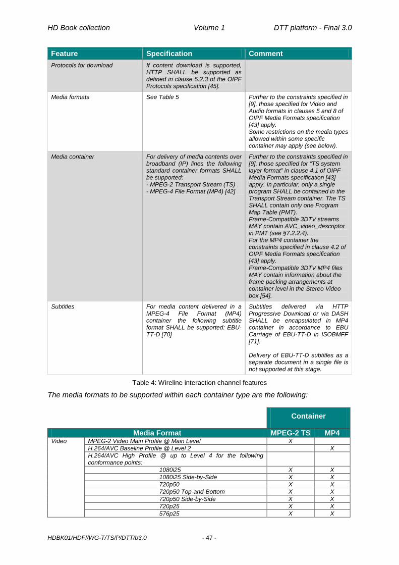
HD Book collection Volume 1 DTT platform - Final 3.0
HDBK01/HDFI/WG-T/TS/P/DTT/b3.0 - 47 -
Feature Specification Comment Protocols for download If content download is supported,
HTTP SHALL be supported as defined in clause 5.2.3 of the OIPF Protocols specification [45].
Media formats See Table 5 Further to the constraints specified in [9], those specified for Video and Audio formats in clauses 5 and 8 of OIPF Media Formats specification [43] apply. Some restrictions on the media types allowed within some specific container may apply (see below).
Media container For delivery of media contents over broadband (IP) lines the following standard container formats SHALL be supported: - MPEG-2 Transport Stream (TS) - MPEG-4 File Format (MP4) [42]
Further to the constraints specified in [9], those specified for “TS system layer format” in clause 4.1 of OIPF Media Formats specification [43] apply. In particular, only a single program SHALL be contained in the Transport Stream container. The TS SHALL contain only one Program Map Table (PMT). Frame-Compatible 3DTV streams MAY contain AVC_video_descriptor in PMT (see §7.2.2.4). For the MP4 container the constraints specified in clause 4.2 of OIPF Media Formats specification [43] apply. Frame-Compatible 3DTV MP4 files MAY contain information about the frame packing arrangements at container level in the Stereo Video box [54].
Subtitles For media content delivered in a MPEG-4 File Format (MP4) container the following subtitle format SHALL be supported: EBU-TT-D [70]
Subtitles delivered via HTTP Progressive Download or via DASH SHALL be encapsulated in MP4 container in accordance to EBU Carriage of EBU-TT-D in ISOBMFF [71]. Delivery of EBU-TT-D subtitles as a separate document in a single file is not supported at this stage.
Table 4: Wireline interaction channel features
The media formats to be supported within each container type are the following:
Container
Media Format MPEG-2 TS MP4 Video MPEG-2 Video Main Profile @ Main Level X
H.264/AVC Baseline Profile @ Level 2 X H.264/AVC High Profile @ up to Level 4 for the following conformance points:
1080i25 X X 1080i25 Side-by-Side X X 720p50 X X 720p50 Top-and-Bottom X X 720p50 Side-by-Side X X 720p25 X X 576p25 X X

HD Book collection Volume 1 DTT platform - Final 3.0
HDBK01/HDFI/WG-T/TS/P/DTT/b3.0 - 48 -
Container
Media Format MPEG-2 TS MP4 576i25 X X HEVC Main 10 Profile @ up to Level 4.1 for the following conformance points:
X X
1080p50 X X 1080p25 X X 720p50 X X 720p25 X X 540p5011 X X
Audio MPEG-1 Audio Layer I & II12 X AAC-LC up to level 2 for stereo and level 4 for multichannel (5.1) X X HE-AACv1 up to level 2 for stereo, level 4 for multichannel (5.1) X X Enhanced AC-3 (aka Dolby Digital Plus) up to 5.1 channels X X
Teletext EBU Teletext carried in DVB streams X Subtitles DVB Subtitles X
EBU-TT-D Subtitles X
Table 5: Container/media compatibility matrix
UHD receivers SHOULD also support DVB’s UHDTV contents, as defined in [9], delivered via IP (TS and MP4 container, including the DASH case), which call for HEVC Main 10 Profile @ Level 5.1 video decoding [9][74] for the following conformance points:
• 2160p50 • 2160p25.
Maximum bit rate of UHDTV video delivered over broadband (IP) lines that UHD receivers SHALL be able to correctly decode and present for Streamed CoD services is 25 Mbit/s (HTTP). In order to make video encoded with H.264/AVC Baseline Profile decodable also by a Main/High Profile decoder, support of AVC error resilience tools included in Baseline Profile is OPTIONAL (i.e. constraint_set1_flag is equal to “1” in case of Baseline Profile). Particular cases of “self-contained” contents which can be delivered over broadband (IP) lines are audio-only streams. The following formats SHALL be supported for such streams:
- MPEG-1 Audio Layer III - HE-AACv1 - AAC-LC
Audio-only streams based on the latter two formats can be carried either using Audio Data Transport Stream (ADTS) [67] or within the MPEG-2 TS and MP4 containers. Usage of MPEG-1 Audio Layer III is restricted to audio-only streams, i.e. it will not be used for audiovisual streams, either broadband or broadcast. Support of DVB Subtitles in conjunction with frame-compatible 3DTV formats is OPTIONAL. When EBU-TT-D subtitles are encapsulated in a MP4 fragmented file used in a DASH presentation, the following MIME type SHALL be used: application/mp4. 11 720p50 and 540p50 (16:9 aspect ratio) are two formats which broadcasters and/or OTT providers might consider for new HEVC near-SD services. 12 It is expected that this old and inefficient audio codec will not be used alongside advanced video codecs like H.264/AVC and HEVC.

HD Book collection Volume 1 DTT platform - Final 3.0
HDBK01/HDFI/WG-T/TS/P/DTT/b3.0 - 49 -
When EBU-TT-D subtitles are delivered as a separate xml document, the following MIME type SHALL be used: application/ttml+xml. The Content Access Streaming Descriptor structure with the syntax and MIME type defined in Annex E.2 of the OIPF DAE specification [73] SHALL be supported to describe content available for streaming. File extensions and MIME types used for the previously defined container formats and for DASH’s MPD manifest file are the following:
Format Extension(s) MIME Type Media Presentation Description (MPD) .mpd application/dash+xml MPEG-2 Transport Stream (TS) .ts, .trp, .mpg video/mpeg or video/mp2t MPEG-4 File Format (MP4) .mp4 video/mp4 MPEG-1 Audio Layer III .mp3 audio/mpeg AAC-LC or HE-AACv1 within MP4 .m4A audio/mp4 AAC-LC or HE-AACv1within ADTS .aac audio/aac Content Access Streaming Descriptor .cad application/vnd.oipf.ContentAccessStreaming+xml Content Access Download Descriptor .cad application/vnd.oipf.ContentAccessDownload+xml
Table 6: File extensions and MIME types for the various container formats
If Media Segments are protected, the corresponding <AdaptationSet> or <Representation> element in the MPD SHALL have at least one <ContentProtection> child element as described in MPEG-DASH [60]. In case of mismatch between DRM metadata provided in the MPD and DRM metadata embedded in the content, the latter (DRM metadata in the media content) has always precedence unless defined otherwise. For the sake of backward compatibility with DASH profile defined in previous HD-Book versions, implementations SHOULD comply with the following additional constraints: In case of ISOBMFF container each ‘moof’ box SHALL contain only one track
fragment box ‘traf’ and associated media data box ‘mdat’ SHALL contain only the media samples referenced from that track fragment box
The Movie Fragment, which consists of a ‘moof’ box and a ‘mdat’ box, SHALL correspond to a Segment element in a DASH MPD.
Representations described in a MPD MAY be organized in up to 16 different <AdaptationSet> elements for each Period
In each <AdaptationSet> element is possible to describe no more than 16 different representations for video/audio tracks
In case of multiple <AdaptationSet> elements containing different video representations the receiver can select the first one it is able to present
In case of multiple <AdaptationSet> elements for the same media component (e.g.: video) the receiver SHALL select by default the one with a Role element with a value of “main” according to urn:mpeg:dash:role:2011 scheme. If such a Role element is not defined the receiver can select the first <AdaptationSet> element it is able to present
Representations included in an <AdaptationSet> element MAY vary in terms of codec Profile@Level, Resolution, and Bitrate
Media Segments SHALL have a minimum duration of 2s, except for the last media segment which MAY be shorter.
6.1.2.2. Mobile interaction channel Any advanced packet-switched mobile connection (e.g. GPRS over EDGE, HSDPA, LTE, …) can be used as mobile interaction channel.

HD Book collection Volume 1 DTT platform - Final 3.0
HDBK01/HDFI/WG-T/TS/P/DTT/b3.0 - 50 -
6.1.2.3. Presentation of Interaction Channel Type to Applications The values returned by the getType() method of the org.dvb.net.rc.RCInterface class in the MHP specification [25] shall be as follows: Interaction Channel Type Value Returned Comment Wireline PSTN Modem interface TYPE_PSTN (value: 1)
Wireline Ethernet Interface TYPE_CATV (value: 4) For LAN and PPPoE
Mobile Interface TYPE_OTHER (value: 9)
Table 7: Interaction channels values
6.1.2.4. User Instructions Each receiver shall include instructions that clearly describe all the specific conditions to successfully execute connected interactive applications. Examples of such instructions are:
• receivers equipped with an Ethernet port 1. must be connected with a proper cable to a Residential Gateway 2. the customer must have a valid ISP subscription 3. specific interactive applications may not support the broadband interaction
channel. 4. for specific applications access agreements might be required between the
Application Service Provider and the user’s ISP. • receivers equipped with an internal HSDPA modem
1. may have to be connected to a high gain antenna 2. need a valid SIM, inserted in the proper slot, and an active subscription to a
HSDPA service 3. specific interactive application may not support the HSDPA interaction channel
(e.g. based on the speed of the interaction channel). 4. an interconnection agreement must be in place between the interactive
Application Service Provider and the mobile ISP and/or mobile operator of the user
6.1.3. Memory The receiver shall provide at least the following minimum memory sizes: Feature Minimum Value Comment Flash Memory 8 MByte of PMS (persistent non-
volatile memory) dedicated and shared between all the broadcasters
Memory space effectively available, net after an eventual MHP security system. At least further 8 Mbytes of PMS shall be reserved for MHP 1.1.3 stored applications.
SDRAM Memory 16 MByte not contiguous net (Java heap SDRAM memory), available on request for MHP application use.
Memory has to be freed up to the maximum amount of 16 Mbytes (RECOMMENDED 24 MByte) when an MHP application is loaded. This condition is testable by loading into RAM a specific MHP application with a 16/24 MByte footprint.
Table 8: Memory capacity requirements

HD Book collection Volume 1 DTT platform - Final 3.0
HDBK01/HDFI/WG-T/TS/P/DTT/b3.0 - 51 -
6.1.4. I/O Connectors The following requirements complement, modify or extend the requirements of the E-Book, which remain valid where nothing specific is said hereunder.
6.1.4.1. Mandatory Connectors The following connectors shall be present in any applicable receiver (see comments). Connector Specification Comment Input RF connector. Input: IEC 61169-2 Female, 75
Ohm [82]
Tuner input
SCART Connector (Primary) Peritelevision standard [4] • RGB • CVBS: PAL Out • Audio Output
A/V Control Pin 8
For connection to old TV sets. Only applicable to STBs. As an option, the user menu may offer the possibility to output a Y/C signal instead of the RGB signal. In case of HD or UHD signal, the downsampled SD version has to be presented on this output, both in composite and component mode, with the same user settings defined in the menu page for connection to 4:3 or 16:9 TV sets. Teletext reinsertion on VBI is required (see §8.1.2). The stereo output pins will carry one of the following: • a mono or stereo signal, in the case of the received audio component being mono or stereo; • a two channel downmixed signal, in the case of the received audio component being multi-channel. SCART Connector is OPTIONAL on UHD STBs.
Output SPDIF Connector
As per [27] with Optical connector. A second SPDIF output with Electrical (RCA) connector is OPTIONAL. This output may be omitted when the receiver provides a minimum 5 channel audio reproduction system capable of driving at least 5 speakers with a digital bitstream.

HD Book collection Volume 1 DTT platform - Final 3.0
HDBK01/HDFI/WG-T/TS/P/DTT/b3.0 - 52 -
Connector Specification Comment Output HDMI Connector with HDCP content protection
Type A (Female) [38] Automatic audio/video sync is required. HDCP [39] must be ON by default. 1080p50 is the recommended default output format. When Frame-Compatible 3DTV formats are decoded, receivers SHALL transmit an accurate HDMI Vendor Specific InfoFrame (as per section 8.2.3 of [53]) at least once every two video fields Receivers SHALL handle an HDMI Vendor-Specific Data Block (HDMI VSDB) in the E-EDID Data Structure as indicated in section 8.3.2 of [53]. HDMI output(s) on UHD STBs SHALL support HDMI version 2.0 [79] and HDCP version 2.2 Copy Protection [80] when they output with a resolution higher than 1920X1080 a UHD signal as specified in §6.1.2.1. NOTE: When HDCP2.2. is supported by the HDMI sink , it is highly recommended to keep HDCP 2.2 protection constant for all the services to avoid delays when switching channel.
For digital connection of STBs to HD Ready or HD Ready 1080p or UHD displays. According to DIGITALEUROPE HD TV and HD TV 1080p logos’ requirements, a “dynamic” output (unscaled) mode shall be available where the HD output format (720p50 or 1080i25) will match the HD transmission format (720p50 or 1080i25 respectively) based on EDID. By avoiding possible (even multiple) format conversions, such mode would in theory provide the best video quality. But due to limitations in early HDMI/HDCP implementations it would likely cause some substantial extra delay, with respect to a fixed 720p50 or 1080i25 output setting, when moving between services or events with different HD or SD transmission formats. For these reasons, the dynamic output mode shall be available in user menus but not necessarily as the default value. In order to possibly minimize the number of cascaded conversions, when dynamic output mode is selected SD output towards HD Ready or HD Ready 1080p displays SHALL be set to 576p50. To allow connection of UHD STBs to legacy HD displays it SHALL be possible setting output resolution via system menus to UHD (default) or HD (1920x1080). UHD capable STBs outputs UHD video signals, when set to do so: - with a resolution of 3840x2160 pixels - at frame rates 25p and 50p - with a minimum supported bit depth of 8 bits - at a chroma sub-sampling rate of 4:2:0 for 50p and 4:2:2 for 25p - with minimum supported colorimetry according to BT.709 [81]

HD Book collection Volume 1 DTT platform - Final 3.0
HDBK01/HDFI/WG-T/TS/P/DTT/b3.0 - 53 -
Connector Specification Comment Input HDMI Connector with HDCP content protection
Type A (Female) [38] E-EDID support, including HDMI VSDB (Vendor-Specific Data Block) Lipsync-related fields, is required. HDCP [39] must be ON by default. It’s highly RECOMMENDED that 3DTV capable iDTVs interpret HDMI Vendor Specific InfoFrame packet (as per section 8.2.3 of [53]). 3DTV capable iDTVs SHALL contain an HDMI Vendor-Specific Data Block (HDMI VSDB) in the E-EDID Data Structure as indicated in section 8.3.2 of [53].
For digital connection of STBs to HD Ready or HD Ready 1080p TV sets. Support of HDMI ARC (Audio Return Channel) specified in [38] is OPTIONAL. HDMI input(s) on UHD TV sets SHALL support HDMI version 2.0 [79] and HDCP version 2.2 Copy Protection [80]. UHD capable inputs accept UHD video signals: - with a resolution of 3840x2160 pixels - at frame rates 25p and 50p - with a minimum supported bit depth of 8 bits - at a chroma sub-sampling rate of 4:2:0 for 50p and 4:2:2 for 25p - with minimum supported colorimetry according to BT.709 [81]
Ethernet Port RJ 45 Connector Mandatory for receivers with wireline interaction channel also in case they provide (in-house) wireless access13.
Smart card slot ISO 7816 1,2,3 with T=0 and T=1 For CA and non-CA applications Common Interface (CI Plus) EN 50 221, as explained in section
9.1.3, with CI Plus extensions [37] Applicable and mandatory only for iDTVs with screen diagonal over 30cm (13”).
USB Port (Host) USB Type A Connector Compliant with USB 2.0 or later specification [52]. For user-managed software upgrade and/or for attaching external storage media
Table 9: Mandatory connectors table
6.1.4.2. Optional Connectors The following table includes a non-exhaustive list of connectors which might be present in some receivers. When present the specifications given therein do apply. Connector Specification Comment Output HDMI Connector with HDCP content protection
Type A (Female) [38] Automatic audio/video sync is required. HDCP [39] must be ON by default.
For digital connection to other external equipment (e.g. Home Theater, Video Projector).
13 An USB port could actually turn into an Ethernet (wired or wireless) or advanced mobile (GPRS, EDGE, UMTS, HDSPA) port through a suitable adapter but the sole presence of such a port doesn’t fulfil the requirement. A receiver with USB port will be considered compliant with this requirement only if the aforementioned adapter would come bundled with the receiver itself.

HD Book collection Volume 1 DTT platform - Final 3.0
HDBK01/HDFI/WG-T/TS/P/DTT/b3.0 - 54 -
Connector Specification Comment Output RF connector (pass-through)
IEC 61169-2 Male [82]
“Loop through” facility. Only applicable to STBs. Necessary to transmit the signal from the receiving antenna to a VCR, and/or to a TV set. In presence of the RF modulator, this output carries also, on a user selectable channel, the digital (decoded) signal
SCART In Connector (1) Peritelevision standard [4] • RGB In • CVBS: PAL In • Audio In • A/V Control Pin 8
Applicable only to iDTVs, for connecting legacy SD devices.
SCART Connector (Secondary) • CVBS: PAL Out • Audio: Output • Y-C (super VHS)
Useful to record Digital Channels on a VCR. Such output must not to be affected by OSD (On Screen Display) graphics. Applicable only to STBs. In case of HD signal, the downsampled SD version has to be presented on this output, either/both in composite or/and component mode (if present), with the same user settings defined in the menu page for connection to 4:3 or 16:9 TV sets. Teletext reinsertion on VBI is recommended (see §8.1.2). The stereo output pins will carry one of the following: • a mono or stereo signal, in the case of the received audio component being mono or stereo; • a two channel downmixed signal, in the case of the received audio component being multi-channel.
SCART Connector (Primary) Peritelevision standard [4] • RGB • CVBS: PAL Out • Audio Output
A/V Control Pin 8
For connection to external legacy SD equipment. As an option, the user menu may offer the possibility to output a Y/C signal instead of the RGB signal. In case of HD signal, the downsampled SD version has to be presented on this output, both in composite and component mode, with the same user settings defined in the menu page for connection to 4:3 or 16:9 TV sets. Teletext reinsertion on VBI is required (see §8.1.2). The stereo output pins will carry one of the following: • a mono or stereo signal, in the case of the received audio component being mono or stereo; • a two channel downmixed signal, in the case of the received audio component being multi-channel.

HD Book collection Volume 1 DTT platform - Final 3.0
HDBK01/HDFI/WG-T/TS/P/DTT/b3.0 - 55 -
Connector Specification Comment RCA Connectors (Composite) • 1 Video
• 2 Audio (left/ right)
In case of HD signal, the composite downsampled SD version has to be presented on the video output, with the same user settings defined in the SCART menu page for connection to 4:3 or 16:9 sets. Teletext reinsertion on VBI is required. The stereo output connector will carry one of the following: • a mono or stereo signal, in the case of the received audio component being mono or stereo; • a two channel downmixed signal, in the case of the received audio component being multi-channel.
RCA Connectors (Component) • 3 Video (YPbPr) as per CEA 770.3
• 2 Audio (left/ right)
In case of HD signal, the composite downsampled SD version has to be presented on the video output, with the same user settings defined in the SCART menu page for connection to 4:3 or 16:9 sets. The stereo output connector will carry one of the following: • a mono or stereo signal, in the case of the received audio component being mono or stereo; • a two channel downmixed signal, in the case of the received audio component being multi-channel.
Serial data port (RS-232) 9-pin D-sub connector Female SIM slot Receptacle for standard SIM.
Access to the SIM slot shall not need opening the case of the receiver.
For receivers with mobile interaction channel. The slot may be either inside the receiver box itself or in an external device.
Mobile high gain antenna connector
One of three possible standards • RP TNC female • RP MC Card female • RP SMA female
For receivers with mobile interaction channel.
Table 10: Optional connectors table
6.1.4.3. Audio outputs matrix The following matrix specifies which audio shall be presented on which output (if present) of a compliant receiver, based on the received signal, both for broadcast and broadband:
HDMI SCART RCA SPDIF Mono/stereo audio (any codec)
Decoded PCM mono/stereo audio
Decoded analog mono/stereo audio
Decoded analog mono/stereo audio
Decoded PCM mono/stereo audio
AC-3 5.1 audio
AC-3 5.1 audio or decoded PCM multichannel audio or stereo downmix of multichannel audio, in the given preference order, based on sink’s capabilities (as per EDID)
Analog stereo downmix of multichannel audio
Analog stereo downmix of multichannel audio
AC-3 stream

HD Book collection Volume 1 DTT platform - Final 3.0
HDBK01/HDFI/WG-T/TS/P/DTT/b3.0 - 56 -
HDMI SCART RCA SPDIF Enhanced AC-3 5.1 audio
Enhanced AC-3 5.1 audio or AC-3 5.1 transcoded stream or decoded PCM multichannel audio or stereo downmix of multichannel audio, in the given preference order, based on sink’s capabilities (as per EDID)
Analog stereo downmix of multichannel audio
Analog stereo downmix of multichannel audio
AC-3 5.1 transcoded stream
HE-AAC v1 5.1 audio
AC-3 or DTS 5.1 transcoded stream or decoded PCM multichannel audio or stereo downmix of multichannel audio, in the given preference order, based on sink’s capabilities (as per EDID)
Analog stereo downmix of multichannel audio
Analog stereo downmix of multichannel audio
AC-3 or DTS 5.1 transcoded stream
Table 11: Audio channel mapping
It SHALL be possible to change via system menus the default output on HDMI, amongst those notified by the sink via EDID.
6.2. Remote Control
6.2.1. Introduction To ensure a common and stable reference for application developers and consumers, it is necessary to specify a certain number of points concerning the remote control. This necessity has been identified and confirmed by different groups (e.g. ETSI STF228 on ”User interoperability criteria”, see Annex B and ref. [21]). The points taken into consideration cover aspects of:
• physical layout of the remote • labelling of the keys • behaviour on “undo” commands • interaction of output from the remote with the OSD • interaction with applications for alpha-numeric input
In all cases where possible, the requirements are based on specifications produced by other bodies (see Annex B). Lastly this chapter contains some advice on good remote control design, taken from extensive research conducted elsewhere (summarized in Annex B). It is highly recommended manufacturers follow this advice – for the benefit of the consumer.
Unlike vertically integrated digital platforms it is not possible to mandate a single remote control design. However, it is essential to have a common minimum of remote-control functionality to ensure that all broadcast services – and in particular interactive applications - are available to the viewer as intended by the broadcaster. In addition, any labelling used needs to be consistent, both to allow the inclusion of on-screen instructions in broadcast services and to enable an easy dialogue with any support staff, e.g. call-centres

HD Book collection Volume 1 DTT platform - Final 3.0
HDBK01/HDFI/WG-T/TS/P/DTT/b3.0 - 57 -
6.2.2. Overview The mandatory keys and key events available to the application are very limited, and thus keys and key event may vary from manufacturer to manufacturer. Even if all necessary (for the consumer and the applications) keys are present on the remote, there is no obligation to make the events available to the application (see Annex B). Events necessary to a smooth operation of interactive TV – such as « undo » - are not specified in the MHP standard and have been specified in different ways by different groups (see Annex B). They might not be treated in a uniform way by manufacturers and thus create inconsistencies for application providers and their communication with the consumer.
6.2.3. Generic functional description of the remote control The remote control is used for different purposes:
Figure 1: Typical Remote Control
- TV/receiver control - channel selection - accessing information about programs and services - interactivity
It is strongly recommended that the keys be grouped together by function, and the groupings should be clearly separated (see “Easy TV” [1] research summary in Annex B).
6.2.4. General Recommendations The following recommendations are based on international studies and on evidence coming out of qualitative research based on DTTV-MHP trials that took in place in Italy.
HD Book collection Volume 1 DTT platform - Final 3.0
HDBK01/HDFI/WG-T/TS/P/DTT/b3.0 - 58 -
6.2.4.1. The Main Remote Receiver remotes need to make possible controlling all the main functions of the TV Set. It has to replace the analogue remote by keeping the same simplicity and user friendliness (few & large keys are needed).
6.2.4.2. Single hand friendly The remote control needs to stay comfortably in one hand and be balanced in weight.
A rubber band can be useful if placed around the border of the remote. The remote will stay in one hand and the keys will be pressed with the thumb. All the
keys need to stay in “thumb range”.
6.2.4.3. Clear structure Keys for normal TV viewing and keys for interactivity and navigation need to be grouped in clearly separated sections of the remote
6.2.4.4. Channel selection Speed: channel selection (video-video switch) should take less than 0,8 seconds both
for an inband or an outband switch. For a channel switch implying a change of hierarchical mode, a maximum of 1 second is tolerable for switching. The switching time shall be calculated using the channel up/down button and will not consider the time for validating the channel number to switch to when using the numeric pad for channel selection..
AV source dedicated key for VCR or DVD (or other receiver) Led on the receiver to indicate the reception of signal coming from the remote.
6.2.4.5. TV controls STBs whose remote gives the opportunity of directly controlling volume on the TV-set were ranked at the top both in Easy-TV and Italian Broadcasters’ research.
6.2.4.6. Now and Next Need for a dedicated key for Now-and-Next information and for accessing on screen help for navigating channels and services.
6.2.4.7. Navigation keys • Navigation keys need to be near and consistently placed. • Colour keys need to be placed following on screen layout. • There has to be one only red key on the remote • Symbols: use well known metaphors.
6.2.4.8. Dimensions Large remote (hand size with large and clearly separated keys). Comfortable to handle (rubbery and rounded). Every key has to be pressed with thumb. Weight: quite consistent. Light means fragile.
6.2.5. The Numeric Pad
6.2.5.1. Overall Function Description The Numeric Pad is used:
• For channel selection • In MHP, for application specific purposes. • For various (manufacturer proprietary) purposes within the receiver’s menus

HD Book collection Volume 1 DTT platform - Final 3.0
HDBK01/HDFI/WG-T/TS/P/DTT/b3.0 - 59 -
6.2.5.2. Requirements for the Numeric Pad
6.2.5.2.1 Time-out for channel selection It is recommended that the time-out for channel selection/switching through numeric pad should be less or equal to 1 second for SD video and 2 seconds for HD video14. Longer time out length is perceived as misfunctional or annoying by users (see Easy-TV research findings in Annex B)
6.2.5.2.2 Labelling of Numeric Pad keys The labelling of the numeric pad keys shall be as shown in the picture. This labelling is fully compliant with standard ETSI ES 202 130 v. 1.1.1 (2003-10) [16]. Letter labels can be also printed on the numeric keys, if they are clearly visible.
6.2.6. Interactive Pad
6.2.6.1. Overall Function Description The Interactive Pad is used:
• For navigating within any receiver proprietary GUI • For navigating within any MHP application
6.2.6.2. Requirements for Interactive Pad No receiver proprietary function shall be assigned to the interactive pad when outside of a proprietary STB menu or sub-menu and, in general, when in TV viewing mode condition (see definition in § 4.1). As a consequence, the arrows should not be used neither for channel switching (Ch+ / Ch – should be used instead) nor for volume adjustments. These functions have to be performed by specific dedicated keys. No key that can bring to a sudden and unexpected killing of an MHP application should be placed near to the interactive pad keys.
Figure 2: The Interactive Pad
The order of the colour keys shall be strictly followed (Red, Green, Yellow, and Blue).
6.2.7. The Navigation Pad
6.2.7.1. Overall Function Description The Navigation Pad is used:
14 It is acknowledged that meeting such targets will depend also on broadcasted signal (e.g. MPEG GOP size) and HDMI/HDCP switching time (if dynamic output mode has been selected)

HD Book collection Volume 1 DTT platform - Final 3.0
HDBK01/HDFI/WG-T/TS/P/DTT/b3.0 - 60 -
• For accessing SI tables data (e.g.: EIT present/following, AIT) • For accessing the overall channel list • For selecting the alternative audio track (if any) • For accessing the EPG application (resident or on-air) • For accessing Subtitles (DVB or Teletext)
Not all the keys shown in the Navigation PAD are mandatory and have to be included on the remote control. Refer to following section in the Remote Control chapter for more detailed specifications.
6.2.7.2. Suggestions for Navigation Pad All the keys in this particular group are receiver proprietary and labels shown in the picture are to be taken as suggestions, but are completely up to the manufacturer for definition. Shape, disposition and order of such keys are up to the manufacturer. It is warmly suggested using keys with a clearly distinct shape for identifying these keys and distinguishing them from Interactive Pad keys.
Figure 3: The Navigation Pad
It is strongly suggested keeping these keys grouped together in order for the user to access them easily. Availability on remote controls, or at least on custom models, of a dedicated “hot” key for people who are blind and visually impaired to easily access Audio Description possibly associated to certain programs is RECOMMENDED.
6.2.8. The TV Pad
6.2.8.1. Overall Function Description The TV Pad is used:
• For accessing to receiver proprietary settings. • For controlling volume and for channel hopping. • For selecting alternative video sources (DVD, VHS, Gaming Consoles…). • To return to TV mode.
Not all the keys shown in the TV Pad are mandatory and have to be included on the remote control. Refer to following section in the Remote Control chapter for more detailed specifications.
6.2.8.2. DGTVi Requirements All the keys in this particular group are receiver proprietary and labels shown in the picture are to be taken as suggestions, but are completely up to the manufacturer for definition. Keys for volume adjustments and for channel up/down scrolling should be easy to identify and clearly separated from the Interactive Pad.

HD Book collection Volume 1 DTT platform - Final 3.0
HDBK01/HDFI/WG-T/TS/P/DTT/b3.0 - 61 -
Figure 4: The TV Pad
6.2.9. The Player Pad
6.2.9.1. Overall Function Description The Player Pad, if present, is used to give interactive applications the possibility to control in an intuitive manner playback of contents received via broadband network, that is:
• to start/pause/resume/stop playback • to skip forward/backward within the content being played back.
6.3. Remote control keys detailed specifications
6.3.1. The Numeric Pad item Keys Status Function Additional specs
1 .. Mandatory MHP standard The letter text labelling has to be followed
Table 12: The Numeric Pad
6.3.2. The Interactive Pad item Keys Status Function Additional specs 2 Mandatory VK_F9 has to be passed to
MHP applications Refer to chapter “Requirements for Undo function”.
3 Mandatory VK_ESC has to be passed to MHP app.
Refer to chapter “Requirements for Undo function”.
4 Mandatory MHP standard – Arrow Up / Down
5 Mandatory MHP standard – Arrow Left
/ Right
6 Mandatory MHP standard
7
Mandatory MHP standard – Red Key
8
Mandatory MHP standard – Green Key
9
Mandatory MHP standard – Yellow Key
10
Mandatory MHP standard – Blue Key
Table 13: The Interactive Pad
Back
Ok
Exit

HD Book collection Volume 1 DTT platform - Final 3.0
HDBK01/HDFI/WG-T/TS/P/DTT/b3.0 - 62 -
Menu
6.3.3. The Navigation Pad item Keys Status Function Additional specs
11
Mandatory
This key gives access to the receiver’s proprietary present and following SI information.
If such key is pressed while IP A/V content is playing and no broadcast A/V content is playing, it SHALL NOT display information related to the event on the broadcast channel. It SHALL either be made available to interactive applications with the code VK_INFO or it SHALL be inhibited.
12
Mandatory This key gives access to the Electronic Program Guide.
The labelling has to be decided by the manufacturer.
13
Optional
This receiver’s proprietary key gives access to the list of MHP application that is related to video services.
The labelling has to be decided by the manufacturer. If such physical key is not present, the same function SHALL be implemented through some other proprietary keys or menus.
14
Optional This key gives access to the receiver’s service list
Audio/video, audio only and stand alone interactive services (see § 7.2.5.1).
15
Optional This key allows the viewer to choose among different audio tracks/languages.
If such physical key is not present, the same function SHALL be implemented through some other proprietary keys or menus. If such key is present and it is pressed while IP A/V content is playing and no broadcast A/V content is playing, it SHALL NOT display information related to the event on the broadcast channel. It SHALL either be made available to interactive applications with the code VK_AUDIO or it SHALL be inhibited.
16
Optional
This key allows the viewer to activate/deactivate presentation of subtitles and to select among different languages, when available.
See Subtitling specs in §8.1.3 If such physical key is not present, the same function SHALL be implemented through some other proprietary keys or menus. If such key is such key is present and it is pressed while IP A/V content is playing and no broadcast A/V content is playing, it SHALL NOT display information related to the event on the broadcast channel. It SHALL either be made available to interactive applications with the code VK_SUB or it SHALL be inhibited.
Table 14: The Navigation Pad
6.3.4. The TV Pad Item Keys Status Function Additional specs
17
Mandatory Access to receiver’s proprietary menu. Labelling is up to the manufacturer.
EPG
List
Audio
Sub
App
Info

HD Book collection Volume 1 DTT platform - Final 3.0
HDBK01/HDFI/WG-T/TS/P/DTT/b3.0 - 63 -
Item Keys Status Function Additional specs
18
Mandatory Increase volume
19
Mandatory Decrease volume
20
Mandatory Switch channel up of one position according to the channel list
21 Mandatory
Switch channel down of one position according to the channel list
22
Optional Selection of external video sources such as DVD, VHS, Gaming Consoles
23
Optional This key allows the viewer to restore the “initial state” of MHP applications.
Refer to Requirements for the “Undo” function § 6.5
Table 15: The TV Pad
6.3.5. The Player Pad item Keys Status Function Additional specs
24 Optional Stop playback Associated to VK_STOP virtual key event
25 Optional Start playback Associated to VK_PLAY virtual key event
26 Optional Pause playback Associated to VK_PAUSE virtual key event
27 Optional Start/pause toggle Associated to VK_PLAY_PAUSE virtual key event
28 Optional Skip forward Associated to VK_FAST_FWD virtual key event
29 Optional Skip backward Associated to VK_REWIND virtual key event
Table 16: The Player Pad
6.3.6. Other Keys item Keys Status Function Additional specs 30 Mandatory Switch on/off the receiver This key SHOULD NOT be red.
31 Mandator
Teletext (see also §8.1.2. MHP standard otherwise. The labelling “Text” is recommended.
32
Optional Muting the volume
Pressing this key once will mute the volume. By pressing the same key again the volume level will be restored at the previous level
Table 17: Other keys
AV
TV
Vol-
Vol+
CH -
CH +
MUTE
TEXT

HD Book collection Volume 1 DTT platform - Final 3.0
HDBK01/HDFI/WG-T/TS/P/DTT/b3.0 - 64 -
6.4. Interaction between (proprietary) receiver GUI and MHP applications
• In case any proprietary receiver GUI is shown on screen while an MHP application is running, the MHP application shall be kept alive and not killed. (The MHP application can either be paused and re-started, or cached and then re-initiated, after the proprietary STB menu or GUI is closed/disappears.)
• In case the application is being loaded when the proprietary receiver GUI is shown, the MHP application shall continue being loaded in the background.
• These behaviours admit only one significant exception: the «MENU» key and the associated proprietary menu GUI. In that case, when MENU key is pressed 2 different behaviours are considered acceptable, namely either
o any running/loading MHP application SHALL be paused until resident menu application is exited, or
o any running/loading/paused MHP application MAY be killed, but a confirmation message SHOULD be presented first to the user and, as soon as the menu GUI disappears from the screen, any MHP autostart application SHALL be automatically re-loaded with no need of re-accessing the channel/mux.
• If MHP applications autostart is set to ON in receiver’s menu and there's at least 1 application in current service signaled to Autostart, APP key (or equivalent) SHALL be disabled.
6.5. Requirements for the “Undo” Function
6.5.1. Preface The areas covered hereafter include:
• General requirement • State of the IRD • Number of keys and labelling of keys • Key mapping and rules for applications
6.5.2. General Requirements To have a consistent man-machine interaction there is a need to have the possibility to
• « undo last » (cancelling the last action). • « undo all » (cancelling all actions, going back to the initial state or going back to the
top menu) Those functions shall be implemented by the applications (resident of downloaded). No « undo » action by the user should lead to an unexpected state, i.e. to a state different from where he started from.
6.5.3. States of the IRD For the user, the state of the receiver will determine how the receiver will behave at the next command (from the remote). As such, the state remains invisible to the user, but the behaviour has to remain consistent. List of possible states:
• (State ’’zero’’): ‘’full kill’’, zapper-like, no MHP capability (e.g. auto-start inactive) • (Initial state): as OoB default or as modified by user

HD Book collection Volume 1 DTT platform - Final 3.0
HDBK01/HDFI/WG-T/TS/P/DTT/b3.0 - 65 -
• (Basic state): Initial state + 1 OTA app (such as a launcher). If no broadcast application available or auto-start has been set to OFF by the user, is equivalent to (Initial state)
• (Top of tree): Home page or top of menu, within an application The out of box (OoB) default shall be MHP auto-start active (see §11) The receiver shall never go to state “zero” if it was not the initial state on accessing the channel.
6.5.4. Other groups’ proposals for key mapping Different specifications groups have addressed (or not) this issue. The main proposals are summarized in Annex B. As there is no coherence between the proposals, and some uniformity is necessary to ensure a consistent interface for the user, the DGTVi has established a set of recommendations:
6.5.5. Keys and Labelling 2 keys are required as a minimum and 3 keys are recommended with following labels: . - 3 Keys
- « Back » for cancel of last action (back) - « Exit » for go to (top of tree) or (basic state) - « TV » for go to (initial state)
-2 Keys - « Back », for cancel of last action (back)
- « Exit », for go to (top of tree) or (basic state)
6.5.6. Key mapping - 3 Keys
- « Back » passes VK_F9 to the application - « Exit » passes VK_ESC to the application - « TV » goes to (initial state), hardwired
- 2 Keys - « Back » passes VK_F9 to the application - « Exit » passes VK_ESC to the application
6.6. Requirements for Text Entry Function
6.6.1. The present situation for text input in I-TV Many remote controls only provide for the minimum set of codes envisioned in the MHP specification (cf. Annex G.5 to TS 101812) i.e. only provide numeric data entry. For alpha-numeric entries, application developers have had to create « helper applications » to create a virtual keyboard, typically through an intermediate sequence of keys, thus potentially contravening to Annex J.5 of the MHP standard. Furthermore key labelling is incomplete and/or different from manufacturer to manufacturer, making difficult communication about text entry with the end-user. The current terminals have different keyboard layout hence hindering easy use and service access. A standardised layout (same or “subset-compatible”) should be used for the same service when applicable, particularly for “special” characters, like “+, “*”, “#”, .….

HD Book collection Volume 1 DTT platform - Final 3.0
HDBK01/HDFI/WG-T/TS/P/DTT/b3.0 - 66 -
6.6.2. Rules for « Request Focus » To ensure consistent user experience, the following rules about requesting focus are defined in [25]:
– an application creating an HScene and placing components into it shall not by default get the input focus for these components
– the application may request to get the input focus by calling Component.requestFocus(). If this is granted and the focus moved to the requested component, this component shall receive input events as defined in J.1 (on page 367).
– the application may request to receive a subset of input events via the org.dvb.event API even when not having the AWT focus.
– On platforms where key events are generated from a sequence of other (intermediate) key events, the intermediate key events shall not be visible to MHP applications by any mechanism. Examples of these intermediate key events include;
o For multi-key press entry (as used in some mobile phones), the keys pressed before the final value is resolved.
o For eventual predictive text entry functionality (T9 or similar systems)
6.6.3. Text Entry General Requirements All receiver manufacturers shall implement text input following the DVB MHP Specification, Appendix A.7 HAVi [25]. In particular, the following classes shall be implemented:
– org.havi.ui.HSinglelineEntry – org.havi.ui.HMultilineEntry
When passing numerical and alphanumerical strings to MHP applications, the receiver shall use, at least, the “SMS like” mode (multi-key press entry) and the remote control as a text input device. This is to be intended as the minimum requirement. In case other text input devices and modes are used, they shall be in addition to the multi-key press entry and shall be implemented by the receiver manufacturer. In any case, and not withstanding which text input mode will be used (the minimum multi-key press entry or any other proprietary and additional mode), no proprietary receiver GUI will be shown on screen covering or overlapping MHP applications graphic layout, when inputting text. As a consequence, no resident virtual keyboard shall be used for inputting text into a MHP application. Labelling of numeric pad for text input shall follow specifications mentioned later in this document In assigning specific alphanumeric characters to single numeric pad keys, the manufacturers shall take ETSI ES 202 130 v. 1.1.1 (2003-10), page 103 table 48 "Keypad assignment for Italian“ as a guideline.
6.6.4. Key Pad Suggested assignment for text entry A subset of the mandatory characters is recommended to be implemented within the overall ETSI character list.

HD Book collection Volume 1 DTT platform - Final 3.0
HDBK01/HDFI/WG-T/TS/P/DTT/b3.0 - 67 -
6.6.4.1. Standard Characters Subset
Key Requirement Subset Character Sequence
Mandatory a b c 2 à A B C
Mandatory d e f 3 è D E F
Mandatory g h i 4 ì G H I
Mandatory j k l 5 J K L
Mandatory m n o 6 ò M N O
Mandatory p q r s 7 P Q R S
Mandatory t u v 8 ù T U V
Mandatory w x y z 9 W X Y Z
Mandatory 0 “space” “new line”
Table 18 : Standard Character subset
6.6.4.2. Special Characters Subset As per ETSI ES 202 130 v. 1.1.1 (2003-10), (page 103 table 48 "Keypad assignment for Italian“) all special characters have to be assigned to numeric key “1”.
Key Requirement Subset Character Sequence
Mandatory
Table 19: Special Character Subset
The subset of special characters listed in the previous table has to be considered as the minimum mandatory requirement for manufacturers. All receivers shall be compliant with the subject ETSI specification.
6.6.5. Text Entry Functions The “multi-key press entry” mechanism has to provide a user experience very similar to that of cell-phone SMS text input. As a consequence, some simple functions have to be implemented in order to improve overall user experience when entering text:
a b c
2d e f
3g h i
4j k l
5m n o
6p q r s
7t u v
8w x y z
9
0
,.;@
1 # 1 , ! . @ “ ; : + - / * ( ) % < > = € ? 1 , ! @ ; : ( % ?
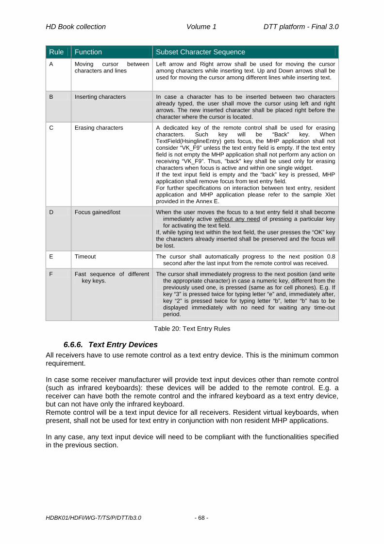
HD Book collection Volume 1 DTT platform - Final 3.0
HDBK01/HDFI/WG-T/TS/P/DTT/b3.0 - 68 -
Rule Function Subset Character Sequence A Moving cursor between
characters and lines Left arrow and Right arrow shall be used for moving the cursor among characters while inserting text. Up and Down arrows shall be used for moving the cursor among different lines while inserting text.
B Inserting characters In case a character has to be inserted between two characters already typed, the user shall move the cursor using left and right arrows. The new inserted character shall be placed right before the character where the cursor is located.
C Erasing characters A dedicated key of the remote control shall be used for erasing characters. Such key will be “Back” key. When TextField(HsinglineEntry) gets focus, the MHP application shall not consider “VK_F9” unless the text entry field is empty. If the text entry field is not empty the MHP application shall not perform any action on receiving “VK_F9”. Thus, "back" key shall be used only for erasing characters when focus is active and within one single widget. If the text input field is empty and the “back” key is pressed, MHP application shall remove focus from text entry field. For further specifications on interaction between text entry, resident application and MHP application please refer to the sample Xlet provided in the Annex E.
D Focus gained/lost When the user moves the focus to a text entry field it shall become immediately active without any need of pressing a particular key for activating the text field.
If, while typing text within the text field, the user presses the “OK” key the characters already inserted shall be preserved and the focus will be lost.
E Timeout The cursor shall automatically progress to the next position 0.8 second after the last input from the remote control was received.
F Fast sequence of different key keys.
The cursor shall immediately progress to the next position (and write the appropriate character) in case a numeric key, different from the previously used one, is pressed (same as for cell phones). E.g. If key “3” is pressed twice for typing letter “e” and, immediately after, key “2” is pressed twice for typing letter “b”, letter “b” has to be displayed immediately with no need for waiting any time-out period.
Table 20: Text Entry Rules
6.6.6. Text Entry Devices All receivers have to use remote control as a text entry device. This is the minimum common requirement. In case some receiver manufacturer will provide text input devices other than remote control (such as infrared keyboards): these devices will be added to the remote control. E.g. a receiver can have both the remote control and the infrared keyboard as a text entry device, but can not have only the infrared keyboard. Remote control will be a text input device for all receivers. Resident virtual keyboards, when present, shall not be used for text entry in conjunction with non resident MHP applications. In any case, any text input device will need to be compliant with the functionalities specified in the previous section.

HD Book collection Volume 1 DTT platform - Final 3.0
HDBK01/HDFI/WG-T/TS/P/DTT/b3.0 - 69 -
6.6.7. Text Entry Layering
Figure 5: Text Entry Layering Schematic
6.6.8. Text Entry Layering - Underlying Considerations • HSinglelineEntry and HMultilineEntry recognize only the MHP minimum set of events.
• HSinglelineEntry and HMultilineEntry shall handle multi-press key entries according
to the specified key pad assignments and behaviour.
• Specialized (proprietary) adapters are in charge of mapping more complex events coming from richer input devices (e.g. VK_A from an infrared keyboard) to the MHP minimum set (e.g. VK_2 VK_2 VK_2 VK_2 VK_2 VK_2).
Text processors, when available, shall act directly on HSinglelineEntry and HMultilineEntry visible output.
6.6.9. MHP applications and Text entry functionality • For objects referring to MHP classes HSinglelineEntry/HMultilineEntry, receiver shall
activate editing mode on method focusGained(FocusEvent e) and de-activate editing mode on method focusLost(FocusEvent e).
• Focus is lost:
1. When object is empty (0 characters) and the keyEvent.VK_F9 is pressed 2. When keyEvent.VK_Enter is pressed
• In order to have a standardized and harmonized behaviour when managing focus
(focusListener) and events (HkeyListener), MHP application shall be compliant with the following Java class.
6.6.9.1. MHP applications and Text entry sample class A comprehensive example is given in Annex E.

Page intentionally left blank

HD Book collection Volume 1 DTT platform - Final 3.0
HDBK01/HDFI/WG-T/TS/P/DTT/b3.0 - 71 -
7. Service Information & Channel Selection On installation, receivers must offer the viewer all services that may be received at the current location. Due to the distributed nature of DTTV transmissions, a receiver may be able to receive more than one instance of a particular service, which may include regional variants of a service, and must handle such an occurrence sensibly from a viewer perspective. The services being broadcast in the DTTV networks will change over time. To ensure that the viewer is always able to access every service being broadcast, the receiver must detect and reflect to the viewer any such changes with minimal viewer involvement. Services may have an associated Channel Number. Broadcasters may use this as a marketing tool for service promotion to the viewer. Consequently, when possible, receivers should present the channels so that a numeric entry will always select the service with the corresponding Channel Number. However, viewers shall also be free to re-order and/or filter the channel list as they require. Access to, and use of, accurate service information is essential if the viewer is to enjoy all of the content being broadcast. Receivers must offer a complete list of available services and information, if available, about the current and following programmes.
7.1. DVB Locator The DVB locator is the unique identifier of a DVB service. It is composed of three elements:
• Original_Network_ID • Transport_Stream_ID • Service_ID
Its format is dvb://<onID>.<tsID>.<sID>[.<ctag>[&<ctag>]][;<evID>][<path>]. (The optional parameter [;<evID>] allows to identify a single event within a service.) To ensure a harmonious use of the relevant codes, a coordinated allocation of codes and code ranges is recommended for the Italian Digital Terrestrial Television environment. The details of the scheme adopted by Italian broadcasters is given in Annex F.
7.2. SI and PSI Information When possible, Italian digital terrestrial operators will respect the rules suggested by the E-Book on service information. However, a receiver specification cannot put any constraints on the broadcast signal because the receiver must be robust against erroneous or incomplete signalling and present all services whenever they are present. Of course, receiver behaviour, in many cases will be dependent on the presence, in the signal, of supplementary signalling. In this sense support to the part of the E-Book which seeks to specify the broadcast signal is not guaranteed.
7.2.1. Notation The same symbols as in the E-book (# 9.1.4 [8]) are adopted for specifying the expected implementation for Broadcast or Receiver.
Meaning Specification applies to:
Broadcast Receiver Mandatory to broadcast – this shall be present in all broadcasts M

HD Book collection Volume 1 DTT platform - Final 3.0
HDBK01/HDFI/WG-T/TS/P/DTT/b3.0 - 72 -
Meaning Specification applies to:
Broadcast Receiver Mandatory to understand – receivers are required to understand and act on this item m
Conditional to broadcast – this shall be present if certain criteria are met (for example, certain signalling is required for CA controlled services) C
Recommended to broadcast – inclusion of this item improves the usefulness of broadcasts to receivers and allows them to provide better facilities to users. It is preferable for broadcasts to include this. However receivers shall be able to work correctly without this information
R
Optional to broadcast – this item is allowed in broadcasts and has a defined meaning. However, receivers shall be able to work correctly without it O
Undefined to broadcast – this item is allowed in broadcasts but has no defined use within this specification. Receivers should ignore this information unless they are designed with information from other specifications that define its use
U
Forbidden to broadcast – this item is not allowed in broadcasts as it may cause confusion to receivers that conform to this specification F
Table 21: Symbols notation as per E-Book
7.2.2. Program Map Table (PMT) The descriptors possibly carried by this table at Program level are the following: Descriptor Tag Status
Conditional access descriptor 0x09 C
Private data specifier descriptor 0x5F C
Table 22: Program descriptors (PMT)
The descriptors possibly carried by this table at Elementary Stream level are listed hereafter. Component Descriptor Tag Status
Any Stream identifier descriptor 0x52 C m
Conditional access descriptor 0x09 C
Private data specifier descriptor 0x5F O
Audio ISO 639 language descriptor 0x0A C m
Private data (AC-3) AC-3 descriptor 0x6A C m
Private data (EAC-3) Enhanced AC-3 descriptor 0x7A C m
Private data (AAC) AAC descriptor 0x7C C m
DVB Subtitles Subtitling descriptor 0x59 C m
Teletext Teletext descriptor 0x56 C m
SSU stream Databroadcast_id descriptor 0x66 O m
Video AVC_video_descriptor 0x28 O m
Table 23: Elementary stream descriptors (PMT)

HD Book collection Volume 1 DTT platform - Final 3.0
HDBK01/HDFI/WG-T/TS/P/DTT/b3.0 - 73 -
7.2.2.1. Multiple components of the same type The PMT may contain multiple instances of components with identical signalling. For example, multiple audio components with the same stream type, language and audio_type, or multiple video components in services providing multi-angle viewing (and single audio). In this case the receiver shall select as default component the one with the lowest PID among those of the same type. However, all the components shall be presented for manual selection when requested by the user. As another example, multiple interactive services listed inside an AIT table shall be presented in ascending order from the lowest application_ID, and if multiple AIT are referenced in one PMT, their order shall also be preserved.
7.2.2.2. HD-specific elementary stream types Further to the stream types
• 0x02 for MPEG-2 or MPEG-1 constrained parameter video streams • 0x03 for MPEG-1 audio streams • 0x05 for MPEG-2 TS private_sections • 0x06 for PES packets containing private data • 0x0B for MPEG-2 DSM-CC type B streams
whose support was already required for SD receivers by DGTVI’s D-Book [36], the following stream_type values SHALL also be supported in the scope of this HD-Book:
• 0x11 for MPEG-4 AAC and MPEG-4 HE AAC packetized elementary streams • 0x1B for H.264/AVC video streams • 0x24 for HEVC video streams
The value of stream_type for an Enhanced AC-3 elementary stream will be 0x06 (indicating PES packets containing private data), same as for AC-3.
7.2.2.3. Supplementary Audio For TV-broadcasting applications, noticeably public service broadcasting, there is often a requirement for commentary or narration audio services to provide for different languages or Visually Impaired or Hearing Impaired audiences.
7.2.2.3.1 DVB solution DVB solution encompasses both receiver-mixed and broadcast-mixed Supplementary Audio. Relevant signalling specifications are contained in new Annex to latest [9] revisions.
7.2.2.3.2 Enhanced AC-3 solution Compliance with the behaviour specified in [9] §6.2.2.2 is required.
7.2.2.4. AVC_video_descriptor This descriptor is used to signal the presence of the frame packing arrangement supplemental enhancement information (SEI) message in the AVC video stream. Thanks to this message the receiver will be able to recognize [57]: the frame-compatible video format used, or currently in use, for the 3DTV service; format switches within a running Frame-Compatible 3DTV service (between 2 3DTV
formats, to/from a 3DTV from/to a 2D HD format). The detailed usage of the frame packing arrangement SEI message for Frame-Compatible 3DTV services is specified normatively in Annex H of [9].

HD Book collection Volume 1 DTT platform - Final 3.0
HDBK01/HDFI/WG-T/TS/P/DTT/b3.0 - 74 -
7.2.3. Network Information Table (NIT) The descriptors possibly carried by this table in first loop are the following:
Descriptor Tag Status
Actual Other Network_name_descriptor 0x40 M m O m
Multilingual_network_name_descriptor 0x5B O m O m
Linkage_descriptor 0x4A C C
Private_data_specifier_descriptor 0x5F C C
Eacem_stream_identifier_descriptor 0x86 O O
Table 24: Network descriptors (NIT first loop)
The descriptors possibly carried by this table in second loop are the following:
Descriptor Tag Status
Actual Other Terrestrial_delivery_system_descriptor 0x5A M m* O
Frequency_list descriptor 0x62 R R
Service_list_descriptor 0x41 R R
Private_data_specifier_descriptor 0x5F C C
Logical_channel_descriptor 0x83 O m O
HD simulcast descriptor 0x88 O m O m
T2_delivery_system_descriptor ext(0x04) M m O
*Receiver shall ignore the majority of the fields of this descriptor, see below § 7.2.3.2
Table 25: Transport stream descriptors (NIT second loop)
7.2.3.1. Eacem Stream Identifier Descriptor (Eacem SD) It is expected that broadcasters in Italy will not use this descriptor.
7.2.3.2. Terrestrial delivery system descriptor Receivers may use the modulation parameters in the terrestrial_delivery_system_descriptor as a recommendation when trying to tune to a multiplex but the receiver shall always be able to detect the modulation from the transmission itself (e.g. assisted by TPS bits). MFN network may include repeaters (or channel translations can be performed in MATV systems): the receiver shall ignore the “centre_frequency” specified in the terrestrial delivery system descriptor. In other words the receiver shall select the service in a DVB-T channel according to the frequency used during the tuning procedure, ignoring the value contained in the NIT. The receiver should take into account the - other_frequency_flag (inside the terrestrial_delivery_system_descriptor) Receiver shall ignore the “bandwidth”, “priority”, “constellation”, “hierarchy_information”, “code_rate”, “guard_interval” and “transmission_mode” values in the terrestrial_delivery_system_descriptor of the NIT. If a change occurs in the “network_id” in the NIT, during transmission, the receiver shall ignore it and continue to present the services already in the list and not delete them.

HD Book collection Volume 1 DTT platform - Final 3.0
HDBK01/HDFI/WG-T/TS/P/DTT/b3.0 - 75 -
If a change occurs in the “network_name_descriptor” the receiver shall ignore it and continue to present the services already in the list and not delete them
7.2.3.2.1 T2 Delivery System Descriptor T2_delivery_system_descriptor is signalled in the extension_descriptor (Tag extension value 0x04). The T2-IRD SHALL uses the system parameters in the T2_delivery_system_descriptor to determine the mapping between original_network_id/network_id/transport_stream_id and T2_system_id/plp_id. The T2-IRD SHOULD uses the other system parameters in the T2_delivery_system_descriptor as a recommendation when trying to tune to a multiplex. The T2-IRD SHOULD, however, always be able to detect these system parameters from the transmission itself (i.e. assisted by L1 signalling). Operators can broadcast the same transport stream in the same network using different system parameter settings, reflected in a different T2_system_id. This allows for optimization of the network coverage in frequency planning involving SFN and MFN combination networks.
7.2.3.3. Other_frequency_flag The terrestrial_delivery_system_descriptor may signal the use of possible alternative frequencies through the other_frequency_flag. According to the SI Guidelines [25], this flag may be used (inter alia) to advise the receiver that an identical multiplex may be receivable on other centre frequencies. The receiver must always be able to receive all the available services in the RF channels. If the same service is available on two different RF channels, both were tuned (with the automatic or manual scan procedure), and both are available to the user. Support by receivers of this flag is OPTIONAL. It is expected that broadcasters in Italy will not use this flag.
7.2.4. Bouquet Association Table (BAT) Even though BAT has been experimentally used for some time in Italy for running applications with a domain defined across multiple services and/or multiple connections within a bouquet, receivers can ignore it.
7.2.5. Service Description Tables (SDT) The descriptors possibly carried by this table are the following:
Descriptor Tag Status
Actual Other Service_descriptor 0x48 M m O m
Component_descriptor 0x50 C m C m
CA_identifier_descriptor 0x53 C m C m
Private_data_specifier_descriptor 0x5F C C
Preferred_name_list_descriptor 0x84 O O
Table 26: Service descriptors
HD Book collection Volume 1 DTT platform - Final 3.0
HDBK01/HDFI/WG-T/TS/P/DTT/b3.0 - 76 -
In presence of a CA_Identifier_Descriptor, the receiver shall always try to present the service to the end user. In case the service is effectively scrambled, and the relevant CA system is not present, the receiver shall present an error message (see 7.5.1.2). The preferred_name_list_descriptor, as defined in [8], provides a list of alternative names, and name identifiers, for the service. This information is quasi-static. New component types have been defined for stream content_type 0x05 (AVC/H.264) to signal in the component_descriptor frame-compatible video component formats. Those required by this specification are: H.264/AVC plano-stereoscopic frame compatible high definition video, 16:9 aspect
ratio, 25 Hz, Side-by-Side (component_type code 0x80); H.264/AVC plano-stereoscopic frame compatible high definition video, 16:9 aspect
ratio, 25 Hz, Top-and-Bottom (component_type code 0x81);
7.2.5.1. Service Types Receivers shall only list a service in their service selection interfaces where the service is of a type, as declared in the service_type value in the Service Descriptor, which the receiver is able to present to the user or to a receiver interface. NB: Users may be confused or frustrated if the receiver presents for selection services that are not decodable by the receiver (such HD services on an SD receiver) or are not intended for user selection (such as receiver firmware update broadcasts). Receivers are required to support at least the following service types: service_type = 0x01, digital television service service_type = 0x02, digital radio sound service (MPEG-1 Layer 1 or 2 audio) service_type = 0x0A, advanced codec digital radio sound service service_type = 0x10, DVB MHP service service_type = 0x16, advanced codec SD digital television service service_type = 0x19, advanced codec HD digital television service service_type = 0x1C, advanced codec frame-compatible plano-stereoscopic HD digital
television service The following signalling SHALL be present for HEVC HD services in accordance with [10] service_type = 0x1F stream_content = 0x9 stream_content_ext = 0x0 component_type = 0x00 (HEVC Main Profile HD, 50 Hz) or 0x01 (HEVC Main 10 Profile HD, 50 Hz) Receivers supporting HEVC SHALL interpret and correctly react to the above signalling (service_type, stream_content, stream_content_ext, component_type).
NOTE: In the future, the same service_type may be used for future formats which may not be supported by the HEVC receiver described in this version of specification. For this reason, it is essential that receivers interpret the four fields described above.
According to DVB SI [10], service_type=0x01 should be used for MPEG-2 SD digital television service. However, it may also be used for services using other encodings, including encodings that have a specific entry, e.g. advanced codec HD digital television service. That doesn’t apply to services using HEVC video coding which SHALL be explicitly and unambiguously signalled as stated above.

HD Book collection Volume 1 DTT platform - Final 3.0
HDBK01/HDFI/WG-T/TS/P/DTT/b3.0 - 77 -
A service, as identified by its DVB triplet, will exclusively be either SD or HD. Support for other service types (for example service_type = 0x06, mosaic service) is optional.
7.2.5.2. Running status Receivers are required to support at least the following values and behaviours for the running_status in SDT: running_status = 1, not running -> display banner running_status = 4, running -> normal behaviour
7.2.6. Event Information Table (EIT)
7.2.6.1. Event Information Descriptors The EIT can carry the following descriptors to meet the requirements of EN 300 468 [10] and TR 101 211 [19]:
Descriptor Tag
Status
Present/Following Schedule
Actual Other Actual Other Linkage descriptor 0x4A O m O m C C
Short event descriptor 0x4D M m M m O m* O m*
Extended event descriptor 0x4E C m C m O O
Component descriptor 0x50 M M O O
CA identifier descriptor 0x53 C C C C
Content descriptor 0x54 R R R R
Multi lingual component descriptor 0x5E O O O O
Parental rating descriptor 0x55 O m O O O
Time shifted event descriptor 0x4F F F F F
Private data specifier descriptor 0x5F C C C C
PDC descriptor 0x69 C C C C
Preferred name identifier descriptor
0x85 O O O O
* Mandatory only if no other EPG than the one based on SI data is available on the receiver
Table 27: Event Information Descriptors
The preferred_name_identifier_descriptor, as defined in [8], may be used in the EIT to identify the preferred service name at the time of an event and so allows a schedule of service names. The “special characteristics” content class in the content_descriptor has been extended to include the following event characteristic for Frame-Compatible 3DTV events [57]:
• Stereoscopic (content_nibble_level_2 code 0x4).
Operators are thus able to highlight events broadcast in a Frame-Compatible 3DTV format in the EIT. Receivers may use this information to highlight such events in the EPG.

HD Book collection Volume 1 DTT platform - Final 3.0
HDBK01/HDFI/WG-T/TS/P/DTT/b3.0 - 78 -
7.2.6.2. Carriage of EIT It is expected that network operators carry data for current and next events concerning the services they are broadcasting, on a multiplex per multiplex basis. This will be done within the ability of the content providers to transfer the relevant data to the network operator.
7.2.6.3. Cross Carriage of EIT It is expected that national network operators will cross carry EIT data, at least for national services. Similar agreements may exist with regional/local network operators. The policy of allocation of TS_ID and S_ID on mixed national or regional networks may influence the carriage of cross-SI among a given number of operators. Therefore it is extremely important that network operator follow the DGTVi recommended procedures for ID allocation and use (see Annex F). A basic requirement when an operator carries EIT p/f of other operators in EIT_other tables is that such functionality shall not have excessive impact on bandwidth or complexity of operation. This can be achieved e.g. by limiting the number of variants when a national network partially splits into regional programming.
7.2.6.4. EIT schedule compression In order to allow efficient transmission of schedule data spanning more than just a couple of days, a private compressed version of EIT schedule tables is hereafter defined. For this purpose and for avoiding possible backwards compatibility issues, new EIT tables are introduced, using “user defined” table_ids in [10]. Namely:
- Table_ids from 0x80 to 0x8F are used for compressed event_information_section - actual_transport_stream, EIT schedule tables
- Table_ids from 0x90 to 0x9F are used for compressed event_information_section - other_transport_stream, EIT schedule tables
Compression algorithms and further details are given in Annex J. In case both raw (uncompressed) and compressed EIT schedule tables are transmitted, the receiver SHALL use the latter ones. In presence of compressed EIT schedule tables all MHP org.dvb.si classes and methods applicable to EIT schedule tables SHALL refer to the compressed ones.
7.2.7. Summary of mandatory tables Table Actual Other
Program association table M m N/A
Program map table M m N/A
Conditional access table C N/A
Network information table M m O m
Bouquet association table U N/A
Service description table M m M m
Event information table present/following M m M m
Event information table schedule O m* O m*
Event information table schedule (compressed) O m* O m*

HD Book collection Volume 1 DTT platform - Final 3.0
HDBK01/HDFI/WG-T/TS/P/DTT/b3.0 - 79 -
Table Actual Other
Time and date table M m N/A
Time offset table R m N/A
Running status table U N/A
* Mandatory only if no other EPG than the one based on SI data is available on the receiver
Table 28: List of mandatory tables
7.3. Private Data When private descriptors are present in a broadcast, a private data specifier descriptor SHOULD be used (cf. EN 300 468) to identify the definer of the private descriptor. For the Logical Channel Descriptor, the private data specifier value used in the E-Book, as registered in ETSI TR 101 162, shall be used; it is the one registered for EACEM (then EICTA, DIGITALEUROPE today). The following table lists this value and the other private SI items that are defined within its scope. Organisation/ specification PDSD Private SI information Value Type
EACEM 0x00000028 Eacem stream identifier descriptor 0x86 Descriptor tag
EACEM 0x00000028 Logical channel descriptor 0x83 Descriptor tag
EACEM 0x00000028 Preferred name list descriptor 0x84 Descriptor tag
EACEM 0x00000028 Preferred name identifier descriptor 0x85 Descriptor tag
EACEM 0x00000028 HD simulcast descriptor 0x88 Descriptor tag
Table 29: Private SI recognised in the E-Book
7.3.1. Logical Channel Descriptor The logical channel descriptor provides a default channel number label for services. This information is quasi-static. The logical channel descriptor may be inserted once in the second descriptor loop of the NIT. The logical channel number is not necessarily unique within the same original_network_id (except when its value is zero) but may be re-used for regional variants of a service or for local services with strictly not overlapping coverage. Hence the number is not unique within the original network. The logical channel number does not take into account the service type, i.e. all service types share the same number space. The logical channel number does not take into account the transmission standard, i.e. services transmitted on DVB-T and DVB-T2 share the same numbering space. Syntax No. of bits Type logical_channel_descriptor{
descriptor_tag 8 uimsbf
descriptor_length 8 uimsbf
for (i=0; i<N; i++){
service_id 16 uimsbf

HD Book collection Volume 1 DTT platform - Final 3.0
HDBK01/HDFI/WG-T/TS/P/DTT/b3.0 - 80 -
Syntax No. of bits Type visible_service_flag 1 bslbf
reserved 5 bslbf
logical_channel_number 10 uimsbf
}
}
Table 30: Syntax of the logical channel descriptor
7.3.1.1. Descriptor_tag This shall be assigned to be 0x83.
7.3.1.2. Service_id This is a 16 -bit field which serves as a label to identify this service from any other service within the network. The service_id is the same as the program_number in the corresponding program_map_section. Services shall be included irrespective of their running status.
7.3.1.3. Visible_service_flag When set to ‘1’, this 1-bit field indicates that the service is normally visible and selectable (subject to the service type being suitable, etc.) via the receiver service list. When set to ‘0’ this indicates that the receiver is not expected to offer the service to the user in normal navigation modes. However, the receiver should provide a mechanism to access these services (for example, by direct entry of the logical channel number). See also Receiver rules. Support by receivers of the visible_service_flag is MANDATORY.
7.3.1.4. Reserved All “reserved” bits shall be set to ‘1’.
7.3.1.5. Logical_channel_number This is a 10 -bit field which indicates the broadcaster preference for ordering services. Its use is defined in the following table: logical_channel_number Description
0 Service not suitable for selection by the user a) 1 - 999 logical_channel_number 1000 - 1023 rfu – not usable a ) For example, the value zero may be used for data services only intended for selection from interactive applications or for firmware download services, etc.
Table 31: Logical channel number
Any service with LCN=0 shall be ignored. See also Receiver rules.
7.3.2. The Logical Channel Numbers (LCN) The role of the LCN is to enable user presentation of service numbers in a convenient and familiar form.

HD Book collection Volume 1 DTT platform - Final 3.0
HDBK01/HDFI/WG-T/TS/P/DTT/b3.0 - 81 -
To avoid conflicting allocation of LCNs: • The logical_channel_number should be unique across all the networks that cover the
same geographical region. • The same logical channel number should be reused only in non-adjacent regions, • Regional variants of a service may nevertheless use the same logical channel
number. Receivers need to have a mechanism for handling conflicting LCN allocations either within the same country or on the borders of confining countries (see below).
7.3.3. Network operator rules Network operators and content providers operating within Italy have elected to choose a service numbering scheme between them, in collaboration with the appropriate coordinating authorities. This specification defines the logical channel number concept for conveying such service numbering information to receivers. Network operators should obey the following specification rules in order for receivers to be able to properly operate. Logical channel numbers allocated should be usable directly as service numbers in a receiver. Services with the same triplet (original_network_id/transport_stream_id/service_id) shall have the same logical_channel_number. Within the scope of one network (as defined by the network_id), logical channel numbers shall be allocated uniquely. When defining regional variants of a service, the same logical_channel_number may be used (for example in neighbouring networks). This facilitates defining a consistent and compact national/regional/local channel numbering scheme, as well as indicating to the receiver that services with the same logical_channel_number are similar (regional variants). Proper usage for their networks by Italian and confining broadcasters of NIT network_id values in the ranges officially assigned by DVB to the respective DTT networks (see Annex F) allows receivers to understand which LCNs belong to which country and then to give priority in case of conflicts to those from the country selected at first installation time.
7.3.3.1. Multiples LCNs for a single service Network operators and/or service providers MAY allocate up to four LCNs to a single service. This allows the service to be identified and associated with other services according to different criteria, such as local service, with pay elements, belonging to a specific bouquet and being of specific thematic content. Only handling first LCN per service is mandatory.
7.3.3.2. Invisible services It is recommended to allocate high service numbers to services marked as invisible to avoid accidental collision of service numbers with those of visible services when they are being automatically or manually reallocated.
7.3.3.3. Service number zones The service numbers are divided into two zones: 1- 99: the Preferences Zone 100-999: the Assignment Zone

HD Book collection Volume 1 DTT platform - Final 3.0
HDBK01/HDFI/WG-T/TS/P/DTT/b3.0 - 82 -
Service numbers (LCNs) may be pre-assigned in both zones. Furthermore, a specific range, the Main Overflow (or “Garbage Collector”), has been defined to host services without LCN and services which have lost LCN conflict for another position. The Main Overflow occupies service numbers 850 to 999. In case Main Overflow space would get filled up, free positions from 849 backwards SHALL be used.
7.3.4. Receiver rules Receivers SHALL provide an automatic service numbering facility on the basis of logical channel numbers with the rules set out below. It SHOULD be possible for the user to select, in the set up menu, the possibility to switch off and on this automatic ordering possibility. Default setting SHALL be ON.
7.3.4.1. General rules The receiver SHALL be able to associate with one service (i.e. with a unique triplet) at least the first logical channel number set by the broadcaster in the LC descriptor associated with that service. Support of other possible LCNs (up to 4) associated to the same service is OPTIONAL. When a viewer uses the channel up-down arrows, the receiver SHALL skip all service numbers which are not allocated or are allocated to “invisible” services. In the following sections a comprehensive specification for LCN handling by receivers is provided. This specification is meant to • Accommodate possible LCN conflicts while minimizing the risk of discarding potentially
useful services thanks to the reservation of a “safe” overflow range • Leave the user the ultimate freedom to override any broadcaster-defined LCN • Cope with network evolution (e.g. new services on-air; LCNs introduced later for services
already on-air) • Cope with possible (likely) cross-border LCN conflicts It is offered to manufacturer just as a reference implementation. Manufacturers are free to provide their own alternate implementations provided that the above principles are anyway met.
7.3.4.2. Definitions
7.3.4.2.1 Scan List This is the full list of services created on the basis of the services found by doing a frequency scan. It shall include the Logical Channel Number(s) requested by each service.
7.3.4.2.2 Service List This is the ordered list based on the requested LCNs and after the resolution of the eventual conflicts in the requests. The only user intervention allowed to this list is during resolution of conflicts.
7.3.4.2.3 Master User List Initially, if the user has chosen automatic channel ordering at (re)installation time, equal to the Service List (with maybe the exception of invisible services – see below), this list includes subsequent manual modifications by the user. This is the default list of services that is used by the user.

HD Book collection Volume 1 DTT platform - Final 3.0
HDBK01/HDFI/WG-T/TS/P/DTT/b3.0 - 83 -
7.3.4.2.4 User Favourite List(s) It is recommended that manufacturers implement some form of “favourite channel” list(s) in which the user has full control over channel adding, deleting, ordering and numbering, including the possibility to leave out services even when they have been allocated a valid service number.
7.3.4.3. Logical channel number zero Services associated to logical channel number 0 should be disregarded as part of the process below (irrespective of the value of the visible_service_flag). These services are not intended to be presented as part of the viewer’s service list. These services are not intended to be selectable by viewers.
7.3.4.4. Invisible services • Receivers shall support a “default” mode in which they will not show services marked
“invisible” in their user service list or selectable in normal P+/P - browsing. • The receiver shall ignore the presence of “invisible” services when (re-) allocating
services to service numbers requested by “invisible” services. • Receivers shall support a mode (for example as a service mode or as an installation
option) in which it will allow direct selection of all services (irrespective of being marked invisible) by the user. This mode may display all services also as part of the Service List in this mode.
• It is a manufacturer option to combine the two modes mentioned above, by allowing direct selection of “invisible” services while not showing them as part of the Master User List.
• Usually, “invisible” services should not be allocated a Logical Channel Number, and thus should be positioned in the Overflow Range.
7.3.4.5. Service List management
7.3.4.5.1 First initialisation When a receiver is first initialised or reinitialised (e.g. because the user applied for a factory reset), it is expected that user will be present in front of the receiver. The receiver shall perform in accordance with the following rules:
a) It should give the user the possibility to choose between automatic (LCN-driven) and manual (based on discovery) service numbering (see above). b) If automatic service numbering has been selected the receiver shall attempt to allocate in the Service List each service with associated LCN(s) to the service number(s) equal to the LCN(s) requested for that service. This rule implies that if there is only one service with a particular logical_channel_number request, it shall be allocated to that service number. c) In the case of the presence of the same service (identical DVB triplet - ON_id, TS_id & S_id) on two different frequencies, the conflict shall be resolved as described in §7.6.5.2. d) In presence of a conflict between different services that request the same logical channel number the receiver shall first check if the conflict would arise between a service from a network from the country selected at first installation time, i.e. from a network whose network_id comes from the range assigned to that country by DVB, and a service from another country. In that case the requested service number will be allocated to the former and the latter will be moved in the Main Overflow. Otherwise the receiver shall: - present the viewer with a menu allowing to select which channel to maintain at the requested position; automatic resolution of the conflict, either based on signal power

HD Book collection Volume 1 DTT platform - Final 3.0
HDBK01/HDFI/WG-T/TS/P/DTT/b3.0 - 84 -
or first/last found during scan, will be performed after expiration of a suitably long timeout - allocate the other service(s) to the next unallocated number(s) in the Main Overflow. e) If a service does not have an associated logical_channel_number, it shall be allocated an available number in the Main Overflow.
The detailed expected behavior for cross-border LCN conflicts resolution is the following: - if a particular LCN position is claimed by only 1 service, it will be granted that position
regardless of its network_id (NID) and of the position claimed (i.e. including LCNs in Main Overflow range)
- if more services are competing for the same LCN position o if only 1 service has its NID within the range 0x3001 - 0x3100 (if Italy has
been selected as Country at installation time,) it will automatically get the requested position
o if more services have their NIDs within the range 0x3001 - 0x3100, the conflict resolution amongst such services is left up to the customer. Possible competing services whose NIDs is outside the range 0x3001 - 0x3100 will be automatically moved to Main Overflow range (850-999)
o if all competing services have their NIDs outside the range 0x3001 - 0x3100, the conflict resolution is left up to the customer
o whatever the above case, all the other services which haven't got the requested position will be moved to Main Overflow range (850-999)
7.3.4.5.2 Adding new services When adding services to the Service List as a result of an update scan (whether manual or automatically, in stand-by or in operate mode), the receiver shall first try to allocate each new service to the number(s) indicated in the LC descriptor, if any. That applies also to each service which is already in the Service List but at a position different than the LCN itself. Should such position be actually free, the receiver will move the subject service there in the Service List, to cope with services which didn’t have an LCN at the time when they were first tuned. In case of conflict (i.e. the number is already occupied by a “non-invisible” service or is requested by several services), the receiver shall proceed with the same rules given above for first initialisation (§7.3.4.5.1). In particular, after signalling to the user that new services are available (as in the procedure described in 7.6.5), the receiver SHALL display a pop-up menu for each case of conflict, to allow the viewer to select which service to allocate to the requested service number. If there is already a service at the requested number, that service SHALL be the first in the list and the one selected by default (e.g. in case of timeout). If the update scan is performed while in stand-by, pop-up menus for conflict resolution SHALL be displayed immediately after leaving stand-by mode.
7.3.4.5.3 Removing a service If, during an automatic or a manual update scan, the receiver decides that a service can be removed from the Service List, it will exclude the service and its service number from the Service List and the Master User List. A service will be considered as removed in case it’s no longer present in the NIT actual and the SDT actual.
HD Book collection Volume 1 DTT platform - Final 3.0
HDBK01/HDFI/WG-T/TS/P/DTT/b3.0 - 85 -
7.3.4.6. Master User List Management
7.3.4.6.1 Creating the Master User List Once the Service List is created or rebuilt, the Master User List shall be created/rebuilt, equal to the Service List.
7.3.4.6.2 Modifying the Master User List The user is free to modify the names in the Master User List, to delete services, and to move services from one number to any another. If the requested number was unoccupied it will be attributed to the service being moved (the original service number becoming available). It the requested number is occupied, there shall be a switch of service numbers (whether determined by LCN requests, manually or automatically) between the services.
7.3.4.6.3 Updating the Master User List When new services are added to the Service List, they shall also be added to the Master User List, with the same service number as in the Service List, but with the following complementary rules:
- If a service number (as it appears in the Service List) is occupied in Master User List by a user modified service, the service shall be allocated the next available number in the Main
- User deleted services shall be reintroduced in the Master User List only when there has been a modification in the Service List due to the service being available on a new frequency.
7.3.4.6.4 Renewing the Master User List It is strongly recommend that the user shall have the possibility, at any time, to re-create the Master User List by importing the Service List.
7.3.4.7. User Favourite List(s) Those lists are created and modified at the request of the user. They are not automatically modified by the update of the Service List or of the Master User List.
7.3.4.8. The Preferences Zone In the Preferences Zone (service numbers 1-99), all services numbers (already occupied by a service or “empty”) are available for placing a preferred channel, by the user. When a service carrying a LC descriptor, requests an already occupied service number, the user shall be able to select which service to allocate to the requested number; the other service shall be assigned the first available position in the Main Overflow.
7.3.4.9. The Assignment Zone In the assignment zone, only occupied numbers need to be available to the user to modify the numbering scheme (pre-assigned or done by the receiver). The receiver SHALL manage a Main Overflow range, at the high end of the available numbers.
Overflow Range (“Garbage collector”): the service numbers in this range are assigned to services whose type cannot be identified or is patently erroneous, and to services which cannot find an available number in their category’s range.

HD Book collection Volume 1 DTT platform - Final 3.0
HDBK01/HDFI/WG-T/TS/P/DTT/b3.0 - 86 -
In the absence of a LC descriptor, a receiver shall not try to allocate automatically services to another zone than the Overflow Range, where the services need not be sorted by service type. In case the receiver implements separate lists for TV, radio and application services, a Main Overflow (with the same numbering range) should be included for each service type. In case of conflict in the Assignment Zone (a LCN carrying signal requesting an already used number), the user shall be given the possibility to choose which signal to allocate to the specified service number. The other service shall be redirected to the Main Overflow.
7.3.5. Service variation options
7.3.5.1. Service regionalisation When a service dynamically become regional (e.g. for regional news) it is recommended that the regional transmissions at all times be identified as separate services (different DVB triplets). In this case the service may have the same LCN descriptor: this allows the user in zones common to two or more regionalized services to select which one to allocate to the requested service number.
7.3.5.2. Network re-configuration For major network reconfigurations, it is recommended that the user proceed with a re-installation, even at the risk of losing his/her custom numbering, if any. When the receiver detects a service offer change, which includes the addition and deletion of multiple services and/or networks it shall first remove all services which it can determine positively (see Removing a service) to be removed permanently from the service list, and then add the new services.
7.3.5.3. Change of LCN numbering scheme Any re-arrangement by the broadcasters of LCN numbering of services will be treated as above under network re-configuration. This implies that user changes and non-default allocation of services to service numbers by the receiver should be preserved as much as possible unless a re-installation is done.
7.3.6. HD Simulcast Logical Channel Descriptor The HD Simulcast Logical Channel Descriptor provides a means to override the default channel number label of services for an HD receiver. This information is quasi-static. The HD simulcast logical channel descriptor may be inserted in the second descriptor loop of the NIT. The descriptor may appear more than once in this location. The constraints on uniqueness are the same as those for the logical channel descriptor. Syntax No. of bits Type HD_simulcast_descriptor{
descriptor_tag 8 uimsbf
descriptor_length 8 uimsbf
for (i=0; i<N; i++){
service_id 16 uimsbf
visible_service_flag 1 bslbf
reserved 5 bslbf

HD Book collection Volume 1 DTT platform - Final 3.0
HDBK01/HDFI/WG-T/TS/P/DTT/b3.0 - 87 -
Syntax No. of bits Type logical_channel_number 10 uimsbf
}
}
Table 32: Syntax of the HD simulcast logical channel descriptor
7.3.6.1. Descriptor_tag This shall be assigned to be 0x88.
7.3.6.2. Service_id This is a 16 -bit field which serves as a label to identify this service from any other service within the network. The service_id is the same as the program_number in the corresponding program_map_section. Services shall be included irrespective of their running status.
7.3.6.3. Visible_service_flag When set to ‘1’, this 1-bit field indicates that the service is normally visible and selectable (subject to the service type being suitable, etc.) via the receiver service list. When set to ‘0’ this indicates that the receiver is not expected to offer the service to the user in normal navigation modes. However, the receiver should provide a mechanism to access these services (for example, by direct entry of the logical channel number). See also Receiver rules. Support by receivers of the visible_service_flag is mandatory.
7.3.6.4. Reserved All “reserved” bits shall be set to ‘1’.
7.3.6.5. Logical_channel_number This is a 10-bit field which indicates the broadcaster preference for the ordering of services. This descriptor shall only be interpreted by receivers that are able to decode an advanced codec HD digital television service. The channel number label assignment defined by this descriptor overrides the channel number label assignment defined by the Logical Channel Descriptor that is located in the same network_id. The rules for the set of channel number labels used by this descriptor is the same as the rules for the set of channel number labels used by the Logical Channel Descriptor. In the case where this descriptor assigns to a service (service A) a channel number label which is already assigned to another service (service B) (perhaps by the Logical Channel Descriptor), the receiver shall treat the original service (service B) as having no assigned channel number label and assign one automatically in the normal manner. This descriptor is intended to be used for HD services broadcast in simulcast with the same service in SD so that the HD service appears at the primary channel number label on HD capable receivers while the SD service appears at that label for SD-only capable receivers.
7.3.6.6. HD simulcast LCN operation Expected receiver behaviour is outlined in the following flow chart.

HD Book collection Volume 1 DTT platform - Final 3.0
HDBK01/HDFI/WG-T/TS/P/DTT/b3.0 - 88 -
Process Logical Channel Descriptors whose NID matches the geographic
region and assign LCNs to services.
Start
Assign automatic LCNs to all services with an unassigned LCN and to those services whose NID does not match
the geographic region.
Finish
Search for an unprocessed service specified in the HD simulcast logical channel descriptor that matches the geographic NID and whichsatisfies one of the following conditions:(HD simulcast descriptor service type is HD) OR(service HD simulcast LCN < logical.c.d LCN) OR(HD simulcast service_id does not appear in thelogical channel descriptor)
Found unprocessedservice ?
Signal strength greater than BER threshold value ?
Yes
Yes
HD simulcast logical channel LCNallocated to existing
service ?
Yes
Assigned LCN displaces LCN of an
existing service ?
Find displaced service LCN assignment in the HD
simulcast logical channel descriptor with a valid NID
Alternative LCN allocation found for displaced service ?
Mark displaced service with unassigned LCN
Assign displaced service with LCN from the HD
simulcast logical channel descriptor.
No
Assign service the LCN from the HD simulcast logical
channel descriptor.
No
Yes
No
YesNo
No
Figure 6: HD_simulcast_LCN operation
HD Book collection Volume 1 DTT platform - Final 3.0
HDBK01/HDFI/WG-T/TS/P/DTT/b3.0 - 89 -
7.4. Service-variation options The receivers SHALL follow the rules presented above (§7.3.1).
7.5. Receiver functions
7.5.1. Service Change When changing service, parameters need to be set to deal with video formats, languages and unexpected failures in service selection. The minimum requirements for receiver behaviour during service change are outlined in the following paragraphs.
7.5.1.1. Audio language It is assumed that the user has entered one or more language preferences during the receiver installation process. If the selected service has audio tracks in more than one language, the language is selected according to the user preferences.
• If preferred languages do not match any of the available languages, then the receiver shall automatically select the “undefined” (“und” code of the ISO_639_Language_descriptor) audio stream.
• If “undefined” stream is absent, the stream with the lowest PID (lowest numerical value - unsigned integer) in the specified program shall be selected.
• In case no language descriptor is specified the audio stream with the lowest PID shall be selected.
In addition to this automatic soundtrack selection, it shall always possible for the user to manually select any of the available languages.
7.5.1.2. CA controlled services Where a component cannot be presented due to the presence of scrambling, an error message shall be displayed. Otherwise the receiver shall present the component, even in the presence of a CA descriptor.
7.5.2. Service Not Available If the video component within a video service, the audio component in a radio service or the data component in a data service can not be presented because it is no longer accessible on the registered parameters (PID, etc), an error message is shown to the user indicating that the service can not currently be accessed. In case secondary components are missing, the receiver shall present the main component of the service: e.g. a video service with no audio component shall be presented anyway with no error message. “Service not available” error message SHALL NOT be shown if the following conditions are all met:
- an autostart MHP application is associated to service - application autostart has not been disabled by the user - application's carousel does exist or application URL is reachable
The receiver SHALL present all the components of a service it can present.
7.5.3. Active Format Descriptor Transmission of this description by the broadcaster is OPTIONAL, but, when present, use of this description by the receiver is MANDATORY. As explained in Annex B of ETSI TS 101 154 [9] “The Active Format Description (AFD) describes the portion of the coded video frame that is "of interest". It is intended for use in

HD Book collection Volume 1 DTT platform - Final 3.0
HDBK01/HDFI/WG-T/TS/P/DTT/b3.0 - 90 -
networks that deliver mixed formats to a heterogeneous receiver population. The format descriptions are informative in nature and are provided to assist receiver systems to optimize their presentation of video. “[…] The AFD is intended for use where there are compatibility problems between the source format of a programme, the format used for the transmission of that programme, and the format of the target receiver population. For example, a wide-screen production may be transmitted as a 14:9 letter-box within a 4:3 coded frame, thus optimized for the viewer of a 4:3 TV, but causing problems to the viewer of a wide screen TV. The appropriate AFD may be transmitted with the video to indicate to the receiver the "area of interest" of the image, thereby enabling a receiver to present the image in an optimum fashion (which will depend on the format and functionality of the receiving equipment combined with the viewer's preferences). […] The AFD itself does not describe the aspect ratio of the coded frame (as this is described elsewhere in the MPEG-2 video syntax).” The use, by the broadcaster, of this description allows it to optimize the presentation of its program for both 4:3 and 16:9 displays. Therefore, by default, the receiver shall make use of this descriptor. However, the manufacturer may implement a manual override and/or a manual disable.
7.5.3.1. Syntax and Semantics For standard definition programs, the receiver SHALL recognize AFD transmitted according to [9] Annex B.2.2. In case of HDTV compatible receiver, the receiver SHALL recognize AFD transmitted according to [9] Annex B.3.2.
7.5.3.2. Valid Values for Descriptor All values referenced in [9] Annex B “table B.2 active_format” are valid in the broadcast signal.
7.5.3.3. Behaviour of receiver in presence of AFD The receiver SHALL behave in accordance with “The DTG Receiver Implementation Guidelines” [35]. NB: AFDs supplement and qualify - but do not replace - the aspect ratio flag carried in the MPEG sequence header of digital broadcasts. Receivers must interpret both the aspect ratio flag and the AFD in order to present the image in the correct manner.
7.5.3.4. Analogue output of the receiver The receiver should reinsert WSS data in analogue standard definition outputs according to what is specified in [35].
7.5.3.5. AFD and HDMI Receivers with HDMI output are recommended to provide at least one of the following methods to process aspect ratio and AFD information for video output on HDMI:
• Provide a reformatting function for the video to match the aspect ratio of the display based on AFD, aspect ratio and user preference as per section 6.4.3.5 in [35] (for 16:9 displays). Support for scaling to 4:3 aspect ratio for HDMI is optional (since consumer HD displays are 16:9). Aspect ratio signaling in the HDMI AVI Infoframebits R0..R3, M0, M1 (see CEA-861) shall be set in accordance with the properties of the video on the output.
• Pass the video to the HDMI output unprocessed with respect to AFD and aspect

HD Book collection Volume 1 DTT platform - Final 3.0
HDBK01/HDFI/WG-T/TS/P/DTT/b3.0 - 91 -
ratio scaling, and pass AFD and aspect-ratio signaling in the video to the HDMI output as part of the AVI Infoframe bits R0..R3, M0, M1 (see CEA-861)
7.6. Network Connection (Tuning) A general principle is that any scanning procedure shall make accessible to the user all the services available at a given location. New multiplexes or new channels inside already existing multiplexes will be started over the time both nationally and locally. It is important to make it very easy for the user to enjoy all the new channels and services that are broadcast in DTT, as soon as they are on air, without any need for a manual rescan of the spectrum. This will be the best and most effective way to inform the viewer that new channels and services are available. This will improve the viewer experience and, as a consequence, help the DTT platform to succeed. The receivers should be able to automatically and regularly update the channel and service list without the need of direct intervention by the viewer. This will make much easier for the final user to install the receiver and to keep the receiver updated with all the new channels and services that can be received in his coverage area. Obviously, the viewer has to be able to perform a complete scan at any moment, either manually or automatically. Furthermore, the viewer must have the possibility to disable the automatic channel and service list update procedure.
7.6.1. General Requirements In order to make receivers capable of managing the situations previously described, the following functions SHALL be implemented:
• manual full scan: the procedure, initiated by the user, performs a full (automatic) scan of the spectrum and can be used to update the channel and service lists or to re-install everything from scratch;
• manual scan (single channel): a manual tuning procedure allowing the user to manually select and tune a single VHF/UHF channel (giving for example the channel number)
• automatic full scan: the procedure is initiated automatically by the receiver and performs a full (automatic) scan of the spectrum with the only purpose being to update the lists;
T2-IRDs SHALL provide a single list containing both DVB-T and DVT-2 services. For all the described tuning procedures, receivers SHALL scan the following spectrum bands [2]:
• III-VHF (BW=7MHz with European channel raster), • IV-UHF and V-UHF (BW=8 MHz).
7.6.2. First Installation Procedure • At first installation the receiver SHALL perform an automatic scan over the entire
spectrum bands, as defined in §7.6.1, searching for all the digital services available. • At the end of the scan, all the channels and services found (audio/video/data) are
stored in the channel and service list • If automatic ordering of channels and services mechanism is active (based on a
logical channel numbering scheme) the resulting lists will be organised according to

HD Book collection Volume 1 DTT platform - Final 3.0
HDBK01/HDFI/WG-T/TS/P/DTT/b3.0 - 92 -
the criteria described in section 7.3.4.5. Otherwise the list will be organised according to frequency scan order.
• The receiver SHALL provide an interface allowing the user to access the list and move, rename, discard or restore services from the list.
• When the user discards a service from the list, the service is no longer visualized in the list. It is just stored in the “discarded service list” from which it can be retrieved in any moment by using the “service restore” function.
• When either the manual or automatic scan procedure is started for updating the service list, those services that are included in the discarded services list SHALL not be re-introduced in the main channel list. In case the service list is reinstalled, both the main service list and the discarded service list SHALL be re-initialized.
7.6.3. Manual Full Scan Procedure
7.6.3.1. Update The receiver SHALL:
• update (where necessary) in the list those services which were already existing; for example:
o the receiver shall detect a “service_name” change of a given service and update it unless it was manually edited by the end user;
o if automatic ordering is active, the receiver shall move, if possible based on the rules given in §7.3.4.5 for allocation and conflict resolution, an existing service to the new position indicated by the LCN;
• insert newly available channels or services (audio/video/data) in the relevant list: o if they carry an LCN and automatic ordering is active, the rules given in
§7.3.4.5 for allocation and conflict resolution apply; o if they don’t carry any LCN or if automatic ordering is not active, they will be
appended at the end of the list.
7.6.3.2. Re-install Same as §7.6.2.
7.6.4. Manual Scan Procedure (Single Channel) Same as §7.6.3.1 on single channel.
7.6.5. Automatic full scan (Automatic service list update) To maintain an up to date service list, the receivers SHALL implement an automatic service list update procedure, in accordance with the following requirements:
1. The receiver SHALL perform an automatic scan at regular intervals (at a specified hour and with a specified frequency) to search for new services.
2. The automatic scan can be performed both in standby mode (recommended) and in operate mode (optional). Refer to the following table for automatic channel scan default settings.
3. The automatic scan in either mode can be disabled – separately - by the user, but, as a default setting, it should be active only in stand-by mode. In case user would decide to disable automatic search for new channels in standby mode he/she should be warned that this way the capability of automatically tracking evolution of networks and services will be hindered. For this purpose a message like “Warning! After disabling this feature the receiver won’t be anymore able to keep your channel list automatically updated with respect to services on-air” (Italian translation: “Attenzione! Disabilitando questa funzione il ricevitore non sarà

HD Book collection Volume 1 DTT platform - Final 3.0
HDBK01/HDFI/WG-T/TS/P/DTT/b3.0 - 93 -
più in grado di aggiornare automaticamente la lista canali in base a quelli effettivamente trasmessi”) should be presented.
4. When the receiver performs the scan, looking for new channels, it compares any single service found with the list of services already registered. This comparison will be based on frequency, Ts_id, On_id and Service_id of the services. The comparison SHALL take into account all services including those that were discarded by the user from the channel/service list and are listed in the “discarded channel list”.
5. For those services already registered in the service list, the receiver SHALL: o detect a “service_name” change and update it unless it was manually edited
by the end user; o if automatic ordering is active, move an existing service, if possible based on
the rules given in §7.3.4.5 for LCN allocation and conflict resolution, to the new position indicated by the LCN;
6. If any service is found with frequency, Ts_id, On_id or Service_id different from those of the channels already registered, it will be added to the channel list (in its own category group) according to the following rules: o if new service carries an LCN and automatic ordering is active, the rules given
in §7.3.4.5 for allocation and conflict resolution apply o if new service doesn’t carry any LCN or if automatic ordering is not active, it
will be appended at the end of the list. 7. If any new service is found a message will be shown on screen when the receiver
is switched on (if it was in standby mode) and will be left on screen until the user presses the OK key. The message will be something like: “New channels were found and added to the channel list” (Italian Translation: “Sono stati trovati nuovi canali in onda. I nuovi canali sono stati aggiunti alla lista canali”).
8. In case both the “search for new channels in standby mode” and the “search for new channels in operate mode” options are set on “YES”, than the receiver must start the automatic scan at the time indicated for performing the channel search in operate mode.
9. In case the “search for new channels in operate mode” is available and set on “YES”, at the time specified for starting the procedure, a 30 seconds countdown will appear on screen with a message like the following: “The receiver will start looking for new channels in … seconds”. Italian translation: “Il Box Interattivo comincerà la ricerca di nuovi canali entro … secondi” (mutatis mutandis for IDTV sets). The user will be able to press “OK” for letting the procedure start immediately or “exit” for aborting the procedure. In case the user will choose “exit”, the procedure will be aborted and will not be performed again until the next scheduled time.
10. In case the “search for new channels in standby mode” option is set on “YES”, but the “search for new channels in operate mode” option is available and set on “NO” (or was aborted – refer to previous point), the receiver shall start the scanning procedure some time, implementation dependent, after being put in standby mode (in case the receiver is put in standby mode more than once a day, this procedure has to be performed only once daily).
7.6.5.1. Default settings for automatic scan N. Settings / Italian Translation Default settings
1 “Automatic search for new channels in standby mode” / “Ricerca automatica di nuovi canali in standby” YES / SI’ (MANDATORY)
2 “Automatic search for new channels in operate mode” / “Ricerca automatica di nuovi canali a decoder acceso” NO / NO (if available)

HD Book collection Volume 1 DTT platform - Final 3.0
HDBK01/HDFI/WG-T/TS/P/DTT/b3.0 - 94 -
N. Settings / Italian Translation Default settings 3 “Time” / “Ora” 04:30 AM
4 “Repetition” / “Frequenza” “Daily” / “Quotidiana” = default (“Weekly” / “Settimanale” – other options possible)
Table 33: Default settings for automatic scan
7.6.5.2. Handling of duplicate services In presence of the same service available on different frequencies/Transport Streams, the Receiver shall behave as follows: When identical services (i.e. with the same original_network_id, transport_stream_id and service_id triplet) are received on different frequencies (obtained from different transmitters or generated by the MATV system), the receiver should present to the user all of the instances of the service (i.e. including duplicates). In the channel list, the position associated with the lowest ordinal number should be given to the service with the best QoS. Extra instances of services should be regrouped at the end of the list. The minimum requirement is that only the instance with best C/N out of the services with the same DVB triplet found during scan shall be kept, provided that the situation is revisited at each automatic or manual rescan. In the context of interactive applications (e.g. an EPG) the (unique) DVB Locator of duplicate services shall refer to the one with the best QoS. (In case of equivalent QoS, it shall refer to the service first discovered).
7.6.5.3. Automatic Ordering of Channels and Services in absence of LC descriptor acquisition
If the off-the-air LC descriptor acquisition mechanism is not activated in the receiver, the services shall appear in the order they have been detected (taking into account the procedure described in 7.6.2) and grouped into three categories in the following order:
• TV channels • Radio channels • Channel independent Interactive Services (un-bound interactive services)
Interactive services linked to TV or Radio services shall not be shown.
7.6.6. Network evolution As specified in Table 33 on default settings for automatic scan, the receiver SHALL implement, by default, an automatic scanning procedure, to adapt the receiver to the evolution of the network. As specified in 6.1.1.1, changes in modulation parameters of existing services SHALL be automatically detected.
7.6.7. Default channel numbering of services No default service numbering shall be implemented by manufacturers.
7.7. User interface to the SI carried data This clause describes the minimum set of views of the SI information that receivers shall (M), should (R) or may (O) be able to present to the user.
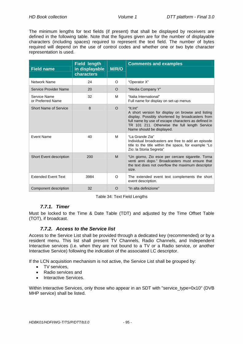
HD Book collection Volume 1 DTT platform - Final 3.0
HDBK01/HDFI/WG-T/TS/P/DTT/b3.0 - 95 -
The minimum lengths for text fields (if present) that shall be displayed by receivers are defined in the following table. Note that the figures given are for the number of displayable characters (including spaces) required to represent the text field. The number of bytes required will depend on the use of control codes and whether one or two byte character representation is used.
Field name Field length in displayable characters
M/R/O
Comments and examples
Network Name 24 O “Operator X”
Service Provider Name 20 O “Media Company Y”
Service Name or Preferred Name
32 M “Italia International” Full name for display on set-up menus
Short Name of Service 8 O “It.Int” A short version for display on browse and listing display. Possibly shortened by broadcasters from full name by use of escape characters as defined in TR 101 211. Otherwise the full length Service Name should be displayed.
Event Name 40 M “La Grande Zia” Individual broadcasters are free to add an episode title to the title within the space, for example “Lo Zio: la Storia Segreta”
Short Event description 200 M “Un giorno, Zio esce per cercare sigarette. Torna venti anni dopo.” Broadcasters must ensure that the text does not overflow the maximum descriptor size.
Extended Event Text 3984 O The extended event text complements the short event description.
Component description 32 O “In alta definizione”
Table 34: Text Field Lengths
7.7.1. Timer Must be locked to the Time & Date Table (TDT) and adjusted by the Time Offset Table (TOT), if broadcast.
7.7.2. Access to the Service list Access to the Service List shall be provided through a dedicated key (recommended) or by a resident menu. This list shall present TV Channels, Radio Channels, and Independent Interactive services (i.e. when they are not bound to a TV or a Radio service, or another Interactive Service) following the indication of the associated LC descriptor. If the LCN acquisition mechanism is not active, the Service List shall be grouped by:
• TV services, • Radio services and • Interactive Services.
Within Interactive Services, only those who appear in an SDT with "service_type=0x10" (DVB MHP service) shall be listed.

HD Book collection Volume 1 DTT platform - Final 3.0
HDBK01/HDFI/WG-T/TS/P/DTT/b3.0 - 96 -
7.7.3. Access to the list of service-bound MHP applications When tuned to a specific TV or Radio service or to an Independent Interactive Service, access to the list of MHP applications associated to that service (usable by the receiver) shall be provided through a dedicated key (recommended) or by a resident menu.

HD Book collection Volume 1 DTT platform - Final 3.0
HDBK01/HDFI/WG-T/TS/P/DTT/b3.0 - 97 -
8. Resident Software and API Enhanced and interactive television services are an essential part of the DTTV proposition. Receivers must fully support all specified functionality. The receiver shall access all Italian broadcast digital terrestrial television, radio and interactive services, based on MHP standard 1.0.3 [22] (1.1.3 [25] for HD receivers). Receivers shall implement the most current version of the specification, to take advantage of bug corrections. This shall include the capability to: efficiently handle Digital Text and Enhanced Broadcast elements of all services; display subtitles (where broadcast) if requested by the viewer; handle both widescreen and 4:3 picture formats as required for the connected display.
8.1. Services
8.1.1. Video Dripping The receiver shall support Video Dripping as specified in the MHP Standard [25]. This is used to visualise dynamic graphical applications (e.g. slide shows).
8.1.2. Teletext Teletext [12] is an important medium in Italy. Not all analogue Teletext services will immediately be converted to MHP applications. Thus there is a need to maintain compatibility with DVB Teletext [11]. The DVB Teletext signal shall be decoded and presented within the receiver and displayed using graphical functions (so-called Teletext Mode 2). That’s particularly true for STBs as (analogue) VBI Teletext signal cannot be carried across (digital) HDMI interface. At least level 1.5 Teletext, as defined in ETS 300 706 [12], shall be supported. One single remote control is then sufficient to view audiovisual services and Teletext using the “Text” key.
It is recommended that VBI data, including Teletext, be reinserted on the VCR SCART (including the Y/C signals) when present (see 6.1.4.2), even if many VCRs will not be able to replay this data. Insertion shall conform to ITU-R BT.653-2 [31]. Teletext data will be inserted from lines 6 to 22 and 320 to 335.
8.1.3. Subtitling Concerning subtitling it is expected that broadcasters will follow the EBU recommendation on subtitling in digital services [7]. However, compatibility must also be maintained with subtitling through Teletext. As a consequence, the receiver SHALL implement DVB Subtitling and Teletext subtitling.
8.1.3.1. DVB Subtitling DVB Subtitling [18] shall be implemented in conformance with the MHP Standard [25].
In order to preserve customers' investments in TV sets with advanced Teletext features, Teletext signal shall be anyway reinserted on the TV SCART and RCA (if present) VBI lines. Insertion shall conform to ITU-R BT.653-2 [31]. Teletext data will be inserted from lines 6 to 22 and 320 to 335.
HD Book collection Volume 1 DTT platform - Final 3.0
HDBK01/HDFI/WG-T/TS/P/DTT/b3.0 - 98 -
HD Subtitling shall be implemented according to [28]. A Display Definition Segment shall only be included in the subtitle stream when the video is HD. The maximum display_width shall be 1919 and the maximum display_height shall be 1079. It is recommended that receivers support Display Definition Segments.
8.1.3.2. Teletext Subtitling Teletext subtitling is part of both Teletext modes described above. Information about the presence of Teletext subtitles shall be obtained from the teletext descriptor and this information shall be made available to the user, at his request (e.g. when pressing the “Sub” key, or through a banner). It is acceptable to make the user select the relevant teletext page for viewing subtitles, as long as a clear message on the availability and modality of access to the subtitles is presented to the user (e.g. a channel banner). Where possible, receivers should be able to display both subtitles and interactive graphics simultaneously. However, not all receivers may be able to do this: in that case, when an application is activated, it shall be able to suspend the rendering of teletext (see also section §13.5.2 Relation to graphics in the MHP Specification [25]).
8.2. Resident Software
8.2.1. Resident Manufacturer Specific Applications
8.2.1.1. Navigator It shall be present. It is defined by the manufacturer (see [1]).
8.2.1.1.1 Handling of input events by the Navigator When the receiver is in TV Viewing Mode (see definition §4.1), it is expected that any running application shall release input keys VK_0 to VK_9. The Navigator shall always be able to handle those input events. The Navigator must also handle all the other keys used for TV viewing (e.g. channel list, volume, and channel up/down). Those keys are different from the keys of the “Interactive Pad” (see §6.2 on the Remote Control, in the D Book [36]).
8.2.2. Parental Control The receiver shall provide a PIN-controlled Parental Control menu to perform the following functions:
1) setting age thresholds (at least for 14 and 18 years) for viewing single events
2) changing the PIN value 3) activating/deactivating PIN checking on 1), 2), 3) above and on the
menu itself The PIN value SHALL be explicitly set by the user during installation procedure. In conformance with National Authority AGCOM Directive 220/11/CSP [66], manufacturers SHALL NOT provide a default value for such a PIN. Reset of the PIN, e.g. in case it was forgotten, can only be achieved through an overall receiver reset to the out-of-the-box status. User SHOULD be duly warned about this drawback during installation procedure.
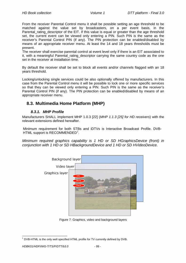
HD Book collection Volume 1 DTT platform - Final 3.0
HDBK01/HDFI/WG-T/TS/P/DTT/b3.0 - 99 -
From the receiver Parental Control menu it shall be possible setting an age threshold to be matched against the value set by broadcasters, on a per event basis, in the Parental_rating_descriptor of the EIT. If this value is equal or greater than the age threshold set, the current event can be viewed only entering a PIN. Such PIN is the same as the receiver’s Parental Control PIN (if any). The PIN protection can be enabled/disabled by means of an appropriate receiver menu. At least the 14 and 18 years thresholds must be present. The receiver shall exercise parental control at event level only if there is an EIT associated to it, with a meaningful Parental_rating_descriptor carrying the same country code as the one set in the receiver at installation time. By default the receiver shall be set to block all events and/or channels flagged with an 18 years threshold. Locking/unlocking single services could be also optionally offered by manufacturers. In this case from the Parental Control menu it will be possible to lock one or more specific services so that they can be viewed only entering a PIN. Such PIN is the same as the receiver’s Parental Control PIN (if any). The PIN protection can be enabled/disabled by means of an appropriate receiver menu.
8.3. Multimedia Home Platform (MHP)
8.3.1. MHP Profile Manufacturers SHALL implement MHP 1.0.3 [22] (MHP 1.1.3 [25] for HD receivers) with the relevant extensions defined hereafter. Minimum requirement for both STBs and iDTVs is Interactive Broadcast Profile. DVB-HTML support is RECOMMENDED1. Minimum required graphics capability is 1 HD or SD HGraphicsDevice (front) in conjunction with 1 HD or SD HBackgroundDevice and 1 HD or SD HVideoDevice.
Figure 7: Graphics, video and background layers
1 DVB-HTML is the only well specified HTML profile for TV currently defined by DVB.

HD Book collection Volume 1 DTT platform - Final 3.0
HDBK01/HDFI/WG-T/TS/P/DTT/b3.0 - 100 -
Support of 1280x720 HD graphics resolution is MANDATORY, as per MHP 1.1.3 Minimum Platform Capabilities ([25] §G.1). Support of 1920x1080 and 960x540 graphics resolutions is OPTIONAL. Implementations SHALL support at least 2 service contexts simultaneously active, e.g. one for broadcast and one for broadband applications running at the same time. The creation of a new service context through createServiceContext() SHALL be supported. If creation of a new service context or demand from an application inside it would exceed platform resources, the InsufficientResourcesException exception will be fired. Until a suitable MHP 1.1.3 test suite becomes available, manufacturers shall provide a self-declaration stating that all MHP 1.1.3 functionalities have been implemented.
8.3.2. Application Manager Application Manager is the resident software module in charge of interpreting AIT signalling, loading/offloading, starting, pausing, killing resident and downloaded applications. It is also responsible for presenting to the user information about applications which may be relevant to him/her, like the list of available applications and possible error messages. Only applications signalled by broadcasters as visible to users (visibility=’11’ in AIT’s Application descriptor) SHOULD be listed to users through APP key or the like. In particular, if Application Manager cannot download an application or an AIT file over the interaction channel because of network problems (e.g. Ethernet cable disconnected), a message like “Verificare la connessione di rete” (“Check network connection”) SHALL be displayed, regardless of receiver’s Application Autostart settings.
8.3.2.1. Autostart Applications In case an application is signalled as "auto-start", all the standard TV functions shall be accessible as normal, and their use shall not cause an interruption to the MHP application downloading. When application autostart is ON, progress loading bars or other icons SHALL NOT be displayed while applications signalled as “autostart” are being loaded or started. Such bars and icons, as well as possible error messages, SHALL instead be displayed in case applications are manually started (because autostart has been switched OFF by the customer or applications are signalled as “present”). Expected behaviour of Application Manager in front of the various combinations of user setting and application type is summarized below:
User setting Application type Loading bar
Application error
Network error
MHP Autostart ON Autostart (Broadcast AIT) NO NO NO
Present (Broadcast AIT) YES YES YES
Autostart/Present (AIT file) YES YES YES
MHP Autostart OFF Autostart/Present (Broadcast AIT) YES YES YES
Autostart/Present (AIT file) YES YES YES
Table 35: Application Manager expected behaviour

HD Book collection Volume 1 DTT platform - Final 3.0
HDBK01/HDFI/WG-T/TS/P/DTT/b3.0 - 101 -
In case a proprietary STB menu is presented on screen that kills any running MHP application, the auto start application shall be re-loaded after the GUI is closed/disappears. Otherwise the MHP application in auto start mode shall be downloaded and started in the background; it shall be shown immediately after the proprietary STB menu/GUI is closed/disappears (see §6.4).
8.3.2.2. Interaction between Resident and Downloaded Applications When a resident application is called by the user or automatically (whether it is an MHP application or a low level manufacturer defined application such as volume level, a list, a set-up menu, etc.) it SHALL NOT kill the active loaded MHP application (see §6.4). Similarly a running resident MHP application SHALL NOT be killed by the launch of another resident low level application (see §6.4 Interaction between (proprietary) receiver GUI and MHP applications).
8.3.3. SDRAM Memory Management In case the maximum amount of available SDRAM memory (see §6.1.3 for minimum memory requirements) is exceeded by the latest started application, the previously loaded and paused MHP applications (if any) shall be purged from memory and the latest loaded application shall be given priority. In case an MHP application in auto start mode is already loaded in memory, this application shall never be automatically purged from SDRAM memory.
8.3.4. Receiver properties In real-life operation, especially in horizontal markets like Italy (but not necessarily only there), the population of receivers reached by MHP applications is far than homogeneous. Different receiver models and different software versions (for whatsoever reason) of the same receiver model receive in a given area at a certain point in time the same MHP application. There could be situations, like functional limitations or bugs in a particular model and/or software release, where an MHP application should behave differently when executing on a particular receiver model with a specific software version. Even though java system properties supposedly exposed by receivers through MHP’s System.getProperty() method would be useful for this purpose
1) they're not necessarily present in any receiver model 2) the number and type of properties is different for each receiver model 3) the name of the same property (e.g. software version) is different for each receiver
model For the above reasons it’s mandatory exposing through MHP’s System.getProperty(), both to signed and unsigned applications, at least the following receiver characteristics (in parenthesis the recommended property name)
- manufacturer name (system.hw.manufacturer) - hardware release (system.hw.version) - model name (system.hw.model) - MAC Address system.hw.macaddress (in hex format with “:” separators)2 - software release (system.sw.version) - loader release (system.loader.version) - receiver type (system.hw.type=”TV” for iDTVs)
2 For receivers with multiple MAC addresses (e.g. for Ethernet and WiFi interfaces ) any of them can be used

HD Book collection Volume 1 DTT platform - Final 3.0
HDBK01/HDFI/WG-T/TS/P/DTT/b3.0 - 102 -
In case of multiple network interfaces (e.g. Ethernet and WiFi), system.hw.macaddress property SHALL expose the currently active one. Certain applications, e.g. those declared in an AIT file, might need to know the service which they were started from, for instance to return there when exiting. For this purpose middleware SHALL maintain a new persistent user preference org.dvb.user.GeneralPreference named “Last Locator” containing last (previous) service locator. Read access by applications to this user preference SHALL always be granted. LastLocator must refer only to conventional DVB services (no HTTPLocator or AIT file).
8.3.5. Behaviour with mixed SD/HD applications It can be envisaged that the following kind of applications will be on-air at the same time on different services:
1. Native HD (16:9) applications associated to HD services 2. Legacy SD (4:3) applications associated to SD (16:9) services 3. Legacy SD (4:3) applications associated to HD simulcast of SD services
By exposing/implementing the relevant properties/methods mandated by the standard (e.g. dvb.display.aspect_ratio), an HD receiver will allow “well-designed” applications to optimize their behaviour in any of the above cases. Scaling of legacy SD applications to high definition graphics resolution, if required by current TV settings, SHALL be performed by the receiver itself. Scaling of SD and HD applications’ graphics/background to ultra high definition graphics resolution on UHD receivers, if required by current TV settings, SHALL be performed by the receiver itself, i.e. either by the UHD TV itself when used as receiver or by the UHD STB receiver connected to an UHD TV set used just as display.
8.3.6. Guidelines for AIT URL The scenario where application signaling comes from the interaction channel rather than the broadcast channel is specified in Section 9.6.1 of MHP 1.1.3 [25]. The following further requirements apply. Same as specified for stored services in Section 9.6.2 of MHP 1.1.3 [25], when service selection to an AIT URL is made, any previously running streamed media decoders SHALL continue to run. It is the responsibility of applications to stop them if so required. Any resources used by such streamed media decoders shall have the lowest possible priority in any resource conflicts. Due to the fact that an application signalled in AIT file can be started only by another application signalled in broadcast AIT or by a resident application which know its URL, Application Autostart settings in the receiver SHALL not affect applications signalled in AIT file. In other words, applications signalled in AIT file as “Autostart” SHALL always be autostarted regardless of receiver’s settings, which are then relevant only for applications signalled in broadcast AIT. For the same reason, progress loading bars or other icons SHALL always be displayed when applications signalled in AIT file are being loaded or started, regardless of receiver’s Application Autostart settings.

HD Book collection Volume 1 DTT platform - Final 3.0
HDBK01/HDFI/WG-T/TS/P/DTT/b3.0 - 103 -
8.3.7. Inter-Xlet Communication (IXC) API Inter-Application and Inter-Xlet Communication API defined in [25] (section 11.7.3) doesn’t put any a priori restriction on the kind of Xlets actually communicating. Under the basic conditions which make communication between 2 (or more) Xlets possible, implementations SHALL then equally support, just to make a few examples, IXC between 2 broadcast applications (i.e. delivered over an object carousel), 2 broadband applications (i.e. delivered over an IP connection), 1 broadcast and 1 broadband application, etc.. Nevertheless there are situations where IXC is not applicable, like for instance when a broadcast application would like to exchange some data with an application signalled in AIT file (in this case service context is changed to AIT file and broadcast applications cannot be signalled in AIT file to possibly make them survive). To circumvent this limitation, implementations SHALL allow any application to access, with read&write rights, a new persistent org.dvb.user.GeneralPreference named "IXC". The minimum amount of persistent storage reserved for this user preference SHALL be 1 kbyte.
8.3.8. Advanced graphics API In order to facilitate the development of applications with advanced 3D graphic effects,
the Java bindings for OpenGL API specified in [55] SHALL be supported in STBs the Java bindings for OpenGL API specified in [55] SHOULD be supported in iDTVs
8.4. Application Environment(s) for broadband media delivery
8.4.1. Procedural Application Environment The Procedural Application Environment (PAE) SHALL be implemented according to the specifications defined above in §8.3 with the clarifications, extensions and restrictions defined in the corresponding clauses below. Special PAE provisions for the DASH Live (Dynamic MPD) case are given in Annex Q.
8.4.1.1. APIs for Streamed CoD In addition to what is specified in Section 11.11.12 of [25] the following classes SHALL support the HTTP protocol:
The constructor for javax.media.MediaLocator - for referencing media files intended to be played while downloading
Methods on javax.media.Manager accepting javax.media.MediaLocator as input parameters - for constructing JMF players for media files intended to be played while downloading.
Implementations SHOULD support also custom player creation by applications through a custom DataSource (javax.media.protocol.DataSource) and a SourceStream (javax.media.protocol.SourceStream). When creating a JMF player, Media Locators which reference files whose MIME-types have been defined in Table 6 will create a player which will play the content while downloading it. If the content cannot be found then such players will never enter the Prefetched state. If an MPD manifest file is referenced in the Media Locator used by an application to create a JMF player, the player will perform all the relevant operations (manifest parsing, switching from one representation to another based on certain conditions, …) without any application involvement.

HD Book collection Volume 1 DTT platform - Final 3.0
HDBK01/HDFI/WG-T/TS/P/DTT/b3.0 - 104 -
If a CAD is referenced in the Media Locator used by an application to create a JMF player, the player will parse the document, retrieve the content URL in the ContentItem element and check, if available, the parental control rating value without any application involvement. If multiple ContentItem elements are included in a CAD, the player will access and play sequentially the related content URLs. Implementations will rely upon MIME-types returned by the server in HTTP responses to determine the container of the content being streamed or downloaded, according to the values listed in Table 5. In case of missing MIME-type, implementations will do their best to tell the container format from the file itself. In the case of “Download CoD,” MIME-types will be stored elsewhere to be used when consuming downloaded media contents. If the container format cannot be determined then such players will never enter the Prefetched state. Media locators containing the question mark character (“?”) SHALL be accepted by implementations. The following controls SHALL be supported for the above mentioned players:
javax.media.Controller and its associated javax.media.ControllerEvent org.davic.media.LanguageControl org.davic.media.AudioLanguageControl org.davic.media.SubtitlingLanguageControl javax.tv.media.MediaSelectControl javax.tv.media.AWTVideoSizeControl org.dvb.media.VideoPresentationControl org.dvb.media.BackgroundVideoPresentationControl org.dvb.media.SubtitlingEventControl org.dvb.media.VideoFormatControl org.dvb.media.DVBMediaSelectControl org.davic.media.MediaTimePositionControl
The following methods SHALL be supported for the above mentioned players:
javax.media.Player.start javax.media.Player.stop javax.media.Player.setRate javax.media.Player.setMediaTime javax.media.Player.getMediaTime javax.media.Player.getDuration javax.media.Player.setStopTime javax.media.Player.realize javax.media.Player.prefetch
The clock rates (0.0) and (1.0) SHALL be supported for the javax.media.setRate method. Any other rate is OPTIONAL. As per JMF specification, time passed to and received from JMF controls is expressed in seconds.
8.4.1.1.1 Player operations Typical operations associated with playing of progressive download contents will be performed using the following APIs:
PLAY - STOP: o javax.media.Player.start() and

HD Book collection Volume 1 DTT platform - Final 3.0
HDBK01/HDFI/WG-T/TS/P/DTT/b3.0 - 105 -
javax.media.Player.stop() (automatic procedure) or
o javax.media.Player.realize() and javax.media.Player.prefetch() and javax.media.Player.start() and javax.media.Player.stop() (step-by-step procedure)
PAUSE - RESUME: o javax.media.setRate(0.0) and
javax.media.setRate(1.0)
SEEK: o javax.media.Player.setMediaTime() or
org.davic.media.MediaTimePositionControl.setMediaTimePosition()
SKIP: o javax.media.Player.getMediaTime() or
org.davic.media.MediaTimePositionControl.getMediaTimePosition() then javax.media.Player.setMediaTime() or org.davic.media.MediaTimePositionControl.setMediaTimePosition()
STOP AT TIME x:
o javax.media.Player.setStopTime(time x)
CHANGE STOP TIME from x to y: o javax.media.Player.setStopTime(Clock.RESET) then
javax.media.Player.setStopTime(time y)
CONTENT DURATION/LENGTH: o javax.media.Player.getDuration() or
javax.media.CachingControl.getContentLength() To allow Streamed CoD of files which have not yet been closed (e.g. ongoing recordings), implementations SHALL try to playback files with zero or invalid content length.
8.4.1.1.2 Time-setting operations When the methods involved in changing the current media time, i.e. javax.media.Player.setMediaTime() and org.davic.media.MediaTimePositionControl.setMediaTimePosition(), are invoked implementations will achieve the result expected by applications, transparently to the applications themselves. The way the result is actually achieved is implementation-dependant and may also depend upon the server (e.g. lack of HTTP Range header support) and/or the content (fixed vs adaptive rate). After the player has successfully retrieved the part of the file containing the indicated media-time and the player has re-entered the Started state a javax.media.MediaTimeSetEvent will be generated. In case of MP4 files, implementations will best match time values passed to the above mentioned methods to the random access points defined in those files. In case of MPEG-2 TS and audio-only files, implementations will do their best to set meaningful time values based on the stream itself (e.g. by treating all media just as if they were fixed rate).
HD Book collection Volume 1 DTT platform - Final 3.0
HDBK01/HDFI/WG-T/TS/P/DTT/b3.0 - 106 -
8.4.1.1.3 Audio language If the selected container has audio tracks in more than one language, the track corresponding to the user preferences, as set during the receiver installation process, will be used by default. Moreover
• If preferred languages do not match any of the available languages, then the receiver shall automatically select the “undefined” (“und” code of the ISO_639_Language_descriptor) audio stream.
• If “undefined” stream is absent, the first listed stream (MP4 case) or the stream with the lowest PID (TS case) in the specified program shall be selected.
In addition to this automatic soundtrack selection, applications can always allow users to manually select any of the available languages through org.davic.media.LanguageControl. In case of DASH contents, languages defined at MPD level must be taken into account for controls provided by org.davic.media.LanguageControl only if language information is missing at container level.
8.4.1.1.4 Streamed CoD control For the purpose of exposing to applications information about underlying Streamed CoD operations, in particular (but not only) for the Adaptive Streaming case, the “Streaming monitoring API” defined since GEM 1.3 [62] has been adopted (see Annex K). It SHALL be supported by receivers.
8.4.1.1.5 Subtitles control Applications can retrieve the list of available subtitles, control their presentation and handle the related events using org.davic.media.SubtitlingLanguageControl and org.dvb.media.SubtitlingEventControl.
8.4.1.1.6 Parental Control For contents delivered through broadband, parental control MAY be enforced through their associated CAD. If a CAD is associated to the content and it contains a ParentalRating element carrying the same country code (in the Region attribute) as the one set in the receiver, the receiver SHALL behave as specified in section §8.2.2 for broadcast contents with respect to the Parental_rating_descriptor of the EIT. Namely, if the value of ParentalRating element is equal or greater than the age threshold set by the user on the receiver, the current content can be viewed only entering a PIN. Such PIN, the age threshold and related menus and procedures are the same described in section §8.2.2. Lack of CAD or of the ParentalRating element for a content means that it’s accessible to everybody or that parental control is exercised at application level.
8.4.1.2. APIs for Download CoD If content download is supported, the “Content download API” specified by OIPF (clause 11.3.4 and Annex E in [46]) SHALL be implemented. The Content Access Download Descriptor as defined in Annex E.1 of the OIPF DAE specification [73] SHALL be supported to describe content available for download.
8.4.1.3. DRM APIs Whatever DRM is supported by the receiver for protecting contents delivered over IP (outside the scope of this document), it SHALL be made accessible to applications through the generic DRM API (org.oipf.drm) defined by OIPF’s PAE Annex G [46].

HD Book collection Volume 1 DTT platform - Final 3.0
HDBK01/HDFI/WG-T/TS/P/DTT/b3.0 - 107 -
In that context the "DRM system name" strings returned by getAgents() method SHALL be built by prefixing the decimal number format of CA_System_ID [19] with "urn:dvb:casystemid:" [46]. In some scenarios, an application may need a way to verify if the device or the user already has the rights to play content without or before accessing the content through the network. The DRM client accesses the licenses locally stored and checks the available rights for the content specified by a ContentID string identifying uniquely the media content. To support this feature an extension of the generic DRM API is therefore needed. In the Class DRMAgent, package org.oipf.drm, add the following method: /** * Checks the local availability of a licence for a specific ContentID and * the rights granted for a specific operation. * @param contentID: The ID of the target content * @param operation: The operation to perform * @throws DRMAgentException. * @returns true if there is a license available locally and if the * associated rights allow performing the requested operation. */ public boolean isOperationValid(String contentID, String operation) throws DRMAgentException { return 0;} The operation strings currently supported are: PLAY
In order to validate the temporal conditions of a license even when is not possible to access a trusted time source, the receiver is allowed to use the time/clock retrieved through live TOT/TDT of any broadcasted stream.
8.4.1.4. OTT content referencing API All the methods listed in MHP [25] clauses 11.11.4.1 (MPEG/DVB specific service) and 11.11.4.2 (Generic service) shall accept or return instances of Objects which describe OTT services addressed by HTTP locators. An HTTPLocator is defined in the Annex L. This locator may reference a media container, an MPD manifest file or an application URL. HTTPLocator doesn’t apply to AIT file. An HTTP locator can be used also to address content delivered via HTTPS.
8.4.2. Other Application Environments Specification of other possible Application Environments and of their integration with the mandatory PAE is outside the scope of this document.
8.5. Resident applications related to broadband media delivery
8.5.1. History The resident navigator SHOULD provide a feature allowing users to browse the list of most recently used broadband applications, i.e. applications which are transported via interaction channel (Section 10.8.1.3 in [25]), and to possibly select one. Only broadband applications signalled by broadcasters as visible to users (visibility=’11’ in AIT’s Application descriptor) SHALL be stored for history purpose.

HD Book collection Volume 1 DTT platform - Final 3.0
HDBK01/HDFI/WG-T/TS/P/DTT/b3.0 - 108 -
8.5.2. Bookmarks A specific key on the remote control SHOULD be available for storing a bookmark to the current broadband application. In conjunction with such key, the resident navigator will provide a feature allowing users to browse the list of bookmarks and to possibly select one. Only applications signalled by broadcasters as visible to users (visibility=’11’ in AIT’s Application descriptor) SHALL be stored for bookmark purpose.
8.6. Maintenance and Upgrade It is very important for the receiver to be able of automatically and regularly look for available software upgrades and to automatically load and install such new software. The procedure must be designed to guarantee both the manufacturers and the broadcasters that over-the-air software upgrades are received and automatically installed on the receiver in the households. This will also make the viewers sure that their receivers are always updated and fully compliant with the applications on air. The process of upgrading shall cause minimal disruption to the viewer. However, to minimise the diversity of deployed software builds and to most efficiently use the available broadcast capacity, the receiver must detect and act upon the broadcast of the relevant software download. After a System Software Update has been performed, user settings like services listings (preferred, etc,) shall be preserved, whenever feasible. Obviously, the viewer has also to be able to perform a manual search for software upgrades in any moment. Further, the viewer has to be allowed to disable the automatic software upgrade procedure.
8.6.1. Automatic software upgrade To allow for a simple user interaction, the receiver shall behave in the following manner:
1. The receiver has to automatically look for available software upgrades over the air.
2. The automatic software upgrade procedure can be disabled by the user. 3. When the receiver looks for available software upgrades, it has to scan all the
multiplexes. 4. The software upgrades put over the air need to be model specific so that there is
no chance that a software intended for a particular receiver model can be downloaded and installed on a receiver with a model different from that to which the software upgrade was intended, as specified in DVB TS 102 006 [23].
5. If any new software version is found, it will be automatically downloaded, but should only be installed after explicit confirmation by the user (manufacturer option).
6. The automatic software upgrade can be performed both in standby mode (mandatory) and optionally in operate mode (at a specified hour and with a specified frequency). Receivers are not required to perform automatic software upgrade while in low power mode. Refer to the following table for automatic channel scan default settings. a) If the "automatic software update in standby mode" option is set to "YES" • in supposedly stable standby conditions (e.g. 30 minutes after standby
mode has been entered) and anyway before entering low power mode (if available), the receiver has to search for new software;
• if receiver is switched on while new software search has already started the update procedure will be aborted

HD Book collection Volume 1 DTT platform - Final 3.0
HDBK01/HDFI/WG-T/TS/P/DTT/b3.0 - 109 -
• if receiver is switched on after new software has been found and download or upgrade is ongoing, the update procedure will be duly completed (loader progress messages should help user understanding what’s going on)
b) If the “automatic software update in operate mode” option is available and set to “YES”, then:
• at the specified time and with the specified frequency, if the receiver is on it has to search for new software;
• at the time the procedure is started, a 30 seconds countdown will appear on screen with the following message: “The receiver will start looking for new software in … seconds”. Italian translation: “Il Box Interattivo comincerà la ricerca d’aggiornamenti software entro … secondi”.
• The user will be able to press “OK” for letting the procedure start immediately or “exit” for aborting the procedure. In case the user will choose “exit”, the procedure will be aborted and will not be performed again until the next scheduled time.
7. When new software has been installed, then (after the receiver has been automatically rebooted, if necessary, and switched on if it was in standby) a message like the following shall appear on screen: “Your receiver was successfully upgraded. New features are now available.” (Italian Translation: “Il Box interattivo è stato aggiornato. Nuove funzionalità sono state aggiunte”). A further message could be displayed briefly describing what functionalities were added to the receiver. This message is up to the manufacturer and is intended for informing the user on what features were added on the receiver. This additional message is not mandatory, but it is strongly recommended. This message will even contain the manufacturer’s call centre telephone number (if any) or, at least, a web site where finding the description of such new functionalities.
8. If new software is found and installed the message described above should be displayed and the automatic channel list updating procedure should be skipped. It is absolutely mandatory that the message described above is seen by the viewer.
9. The message will stay on the screen until the viewer presses the OK key. 10. It is strongly recommended that, within the receiver menu, a section is provided
for describing the new features of the last downloaded software. N. Settings / Italian Translation Mandatory default settings 1 “Automatic software upgrade in stand by” / “Aggiornamento
automatico del software con Televisore in standby”. YES / SI
2 “Automatic software upgrade in operate mode” / “Aggiornamento automatico del software con Televisore acceso”.
YES / SI (if available)
3 “Time” / “Ora” 04:00 AM
4 “Frequency” / “Frequenza” “Daily” / “Quotidiana” = default (“Weekly” / “Settimanale” – other option possible)
Table 36: Default settings for auto software upgrade
8.6.2. Over The Air Software Update The manufacturers shall implement the DVB System Software Update (DVB-SSU) as defined in [24], using the Simple Profile of DVB Data Downloading as defined in [23]. The receiver shall be able to find out its own DVB-SSU files without relying on the relevant linkage_descriptor in NIT or BAT. In order to optimize overall system resources against a multitude of different receivers, support of DVB-SSU Enhanced Profile, based on UNT (Update Notification Table), is recommended.

HD Book collection Volume 1 DTT platform - Final 3.0
HDBK01/HDFI/WG-T/TS/P/DTT/b3.0 - 110 -
Manufacturers shall provide appropriate recovery measures to cope with possible receiver failure or hang-up during the OTA update.
8.6.2.1. Recommendations for SSU operation The receiver shall be able to acquire a software update with a minimum speed of 64 kbit/s, in marginal reception conditions. Software update speed will not exceed 512kbit/s.
HD Book collection Volume 1 DTT platform - Final 3.0
HDBK01/HDFI/WG-T/TS/P/DTT/b3.0 - 111 -
9. Smart cards, CAs, DRMs and Security 9.1. Smart Cards
Smart cards may be used both for CA and non-CA applications (T-government, T-banking, loyalty cards, …).
9.1.1. Conditional Access Pay TV services or other services with controlled/conditional access are an integral part of the Italian DTTV platform. It is not expected that all network operators/broadcasters present in Italy will agree on a single system. It is even disputable, for anti-piracy and management reasons, that a single system should indeed be used. Based on both CA providers and manufacturers willingness, the CA system(s) adopted by one or more specific operator(s) could be either embedded in the receiver or implemented in a Conditional Access Module (CAM) plugged in a Common Interface (CI) slot.
9.1.2. Embedded CA(s) In this case at least one smart card interface conforming to the ISO 7816 standard, levels 1 to 3 (with T=0 and T=1), shall be available. To improve interoperability and interactions of applications with embedded CA(s), DGTVi originally specified a set of CA API Extensions for. These extensions were submitted to DVB which on their basis have developed the “Content Purchasing API” MHP extension [40]. Such extension is a backward compatible superset of the original DGTVi specification.
9.1.3. Common Interface Receivers complying with this document SHALL be consistent with CI+ specification [37] by the CI Plus Limited Liability Partnership (LLP).
9.1.3.1. Physical engagement The Common Interface Connector and the Module SHOULD be implemented in such a way that the smart card shall be inserted with the contact area facing upwards when horizontal.
9.1.3.2. Backward compatibility Host SHALL provide full backward compatibility to previous version of CI+ (earlier than [37]) and to DVB-CI [15]. In particular, a Host SHALL operate according to the version agreed between Module and Host.
9.1.3.3. CA-API As a particular instance of the requirement about backward compatibility, Host complying with this document SHALL support CA-API extensions as described in [37].
In this latter case, if a CAM is provided with the digital receiver (e.g. in case of iDTV), the CAM provider and the digital receiver provider guarantee the coexistence of more CA systems in the same manner as embedded CA system(s). The CAM provider and the iDTV vendor guarantee the same security level as for CAS embedded.

HD Book collection Volume 1 DTT platform - Final 3.0
HDBK01/HDFI/WG-T/TS/P/DTT/b3.0 - 112 -
9.1.3.4. Implementation guidelines In order to enforce the above requirement on backward compatibility, some recommendations regarding particular scenarios where issues were found are given in the following. Refer to [37] Annex E too, for clarifications about CICAM use cases.
9.1.3.4.1 General 1. Should the CA(s) associated to the tuned service be supported both at Host
(embedded) and Module level, the former SHALL have the priority as active (descrambling) device.
2. By default, during the channel scanning procedure all the channels found SHALL be stored by the device independently from the channel scrambling status.
3. The Host SHALL maintain the last tuned frequency when entering the main menu;
4. To cope with possible Module malfunctioning without requiring extreme measures by customers, like Module extraction/insertion and/or Host power unplug/plug cycles, the Module SHALL be restarted as soon as Host comes out of stand-by (Module power-cycle or Module reset). The exception to this is if the Module is performing some task that requires it to remain operational (e.g. Host is recording and requires the CICAM to continue to descramble).
5. Host first installation while Module is inserted, could lead to two different failure scenarios:
a. Module authentication failure during channel scan, in relation to: i. Lack of signal ii. Muxes carrying bad data in DVB-SI table used to get time-date (TDT and
TOT) In order to avoid these scenarios, Host SHALL send to the Module a RESET command as soon as the first installation is terminated.
b. Host first installation failure. In order to avoid this scenario, Host SHALL ignore any MMI message coming from the Module during first installation process.
6. Host SHALL ignore any Module request, through the Host Control resource, of tuning to a service with dvb://0.x.y locator;
7. Whenever communication between the Host and the Module has been lost, i.e. polling function time out expires (see [15] A.4.1.12), Host SHALL reset the Module, in order to properly restart it
8. Host SHALL NOT start any broadcast application when tuned service is not correctly descrambled (Module not/wrongly inserted, card not/wrongly inserted, lack of proper rights, etc., i.e. all scenarios where user is not able to access the A/V content).
9.1.3.4.2 High Level MMI 1. Host SHALL support the High Level MMI Interface as specified in [15]
2. Host SHALL include in the main menu a CAM defined Menu tree.
3. Host SHALL support MMI Pop-ups.
4. Host SHALL comply with the following requirements applied to MMI pop-ups and CAM menus:
• at least 5 lines SHALL be displayed simultaneously • in case of pop-ups/menus composed by more than 5 lines the display
SHALL support scrolling. • at least 50 characters SHALL be displayed for each line

HD Book collection Volume 1 DTT platform - Final 3.0
HDBK01/HDFI/WG-T/TS/P/DTT/b3.0 - 113 -
5. Host SHALL allow MMI pop-ups to have control of the Remote Control keys until the user exits the MMI itself. MMI messages shall not be automatically closed.
6. Host SHALL allow MMI to support the following RC keys:
• Numeric keys • UP, DOWN, LEFT, RIGHT arrow keys • OK key • Back/Exit key(s)
7. In case a System RC Key (P+, P-, Menu, List, …) is selected by the customer while a pop-up message is displayed, Host SHALL close the popup and perform the related system action.
8. Host SHALL allow MMI pop-ups to have higher video priority over downloaded MHP applications.
9.1.4. Non-CA Services For smart card based non-CA services (T-government, T-banking, loyalty cards, …), the SATSA standard API [34]) introduced in MHP 1.1.2 [25] is required. In particular
• STB receivers are required implementing SATSA • iDTV receivers are recommended implementing SATSA.
As an early adopter of this specification, DGTVi spotted 2 issues within it: 1. SATSA doesn’t provide any means to handle smart card events (card in/out, card
upside-down) 2. Even though SATSA would have no fundamental problem playing with non-Java cards
and Java cards without an Application ID, like a lot of cards used in Italy are (e.g. national/regional government service cards), it would actually raise an exception and stop working in presence of them
DGTVi fixed these 2 issues with 2 addenda which can be respectively found in Annexes H and I. These fixes were submitted to DVB and they were incorporated in MHP release 1.1.2. Since MHP 1.1.3 [25] a cleaner fix for issue 1) has been provided by DVB through the new org.dvb.smartcard package. Implementation of either such package or the above addenda in a receiver deeming compliance with smart card based non-CA services is required. Obviously, smart card based non-CA services require a smart card reader which can come in any of the following receiver configurations: A/ One (or more) smart card interface(s) conforming to the ISO 7816 standard, levels 1 to 3 (with T=0 and T=1). B/ A Common Interface slot populated with a smart card reader module (on iDTVs only). In case A/, switching between service card and conditional access card shall not require re-booting of the receiver or a multi-menu navigation (auto detection and activation of the required protocol is the recommended procedure). In case B/, the smart card reader shall be provided as a default
9.2. Common Encryption In addition to the media formats defined in Table 5, the Common Encryption for ISO Base Media File Format (CENC) [59] SHALL be supported by DRM-enabled receivers. CENC is

HD Book collection Volume 1 DTT platform - Final 3.0
HDBK01/HDFI/WG-T/TS/P/DTT/b3.0 - 114 -
used to protect contents packaged in MP4 container and delivered either with HTTP Streaming or HTTP Adaptive Streaming. The CENC protection scheme enables DRM interoperability at the content level for IP delivery much like Simulcrypt does for CA systems in the broadcast environment. Common Encryption for MPEG-2 TS protected contents is left for further study. The CENC protection scheme SHALL be used with the media formats defined in Table 5 with the combinations defined in the following table:
Media format CENC applicability
Video MPEG-2 Video Main Profile @ Main Level H.264/AVC Baseline Profile @ Level 2 X H.264/AVC High Profile @ up to Level 4 for the following conformance points:
1080i25 X 1080i25 Side-by-Side X 720p50 X 720p50 Top-and-Bottom X 720p50 Side-by-Side X 720p25 X 576p25 X 576i25 X HEVC Main 10 Profile @ up to Level 4.1 for the following conformance points:
1080p50 X 1080p25 X 720p50 X 720p25 X 540p50 X
Audio MPEG-1 Audio Layer I & II AAC-LC up to level 2 for stereo and level 4 for multichannel (5.1) X HE-AACv1 up to level 2 for stereo, level 4 for multichannel (5.1) X Enhanced AC-3 (aka Dolby Digital Plus) up to 5.1 channels X
Table 37: Protected format/media compatibility matrix
On UHD-1 Phase 1 compliant receivers (see §6.1.2.1), the CENC protection scheme SHALL also be supported for HEVC Main 10 Profile @ Level 5.1 video format [9] [74] for the following conformance points:
• 2160p50 • 2160p25.
Protected audio-only streams based on HE-AACv1 or AAC-LC and carried within the containers indicated in the Table above SHALL be also supported. Protected audio-visual content MAY be provided with encrypted audio and video or with encrypted video only (audio is not encrypted). Files extensions and MIME types for the CENC protection scheme are the same already specified in Table 6 for MP4 container, namely:
Format Extension(s) MIME type CENC .mp4 video/mp4
.m4A audio/mp4
Table 38: File extensions and MIME types for the various protected formats
HD Book collection Volume 1 DTT platform - Final 3.0
HDBK01/HDFI/WG-T/TS/P/DTT/b3.0 - 115 -
In case of MPEG CENC, sample auxiliary information SHALL be stored in related “moof” box.
9.3. Broadband Applications Security (BAS) The aim of this section is to address requirements and solutions for Broadband Applications Security (BAS). By “broadband application” we mean an application which is downloaded via HTTP or HTTPS protocol. Although MHP Security Framework has been mandated since the very first D-Book 1.0, back in September 2004, it was never actually activated for broadcast applications for two main reasons:
Lack of a proper certificate infrastructure Poor performance of entry-level (SD) receivers (activation of MHP Security would
have caused a major penalty in signed applications start-up time) This situation has been judged not so dangerous for the relatively tight control existing on broadcast transmissions. While the second issue introduced above has been certainly mitigated in HD receivers, their broadband capabilities have brought into the picture both new opportunities and new threats. For this reason, having confirmed that nothing is going to change for broadcast applications (i.e. they’ll stay unsecured forever, except possible side effects of BAS introduced in the following §9.3.5), the broadband applications security matter has been considered worth of a comprehensive review. This section contains the outcome of this review.
9.3.1. BAS requirements The security requirements to be taken into account for broadband applications are listed in the following:
1. Trusted source: downloading of certain applications might be allowed only from trusted servers.
2. Trusted client: downloading of certain applications might be allowed only towards trusted devices.
3. Device shunning: downloading of certain applications to certain (trusted) devices may be banned by one or more service providers.
4. Confidentiality: certain applications may be transmitted confidentially. 5. Restricted resources: usage of some APIs accessing sensible resources (e.g. tuner,
semi-permanent memory, …) may be granted only to certain applications. 6. Restricted APIs: usage of some specific API instances (e.g. API towards Irdeto cards)
may be granted only to applications of one or more particular service providers.
9.3.2. BAS solution outline Given the restricted scope (broadband-only) of this application security framework, BAS has been heavily based upon HTTPS [63]. Most requirements stated above, in particular 1-4, are in fact intrinsically met “by design” using HTTPS. # Requirement HTTPS applicability 1 Downloading of certain applications might be
allowed only from trusted servers. Yes, by hosting those applications on HTTPS servers and by enabling validation of server’s certificate client side.
2 Downloading of certain applications might be allowed only towards trusted devices.
Yes, by hosting those applications on HTTPS servers and by enabling validation of client’s certificate server side.

HD Book collection Volume 1 DTT platform - Final 3.0
HDBK01/HDFI/WG-T/TS/P/DTT/b3.0 - 116 -
# Requirement HTTPS applicability 3 Downloading of certain applications to
certain (trusted) devices may be banned by one or more service providers.
Yes, by hosting those applications on HTTPS servers and by enabling validation of client’s certificate server side. When certain devices (based on certificates’ granularity) are recognized by that service provider, application won’t be downloaded.
4 Certain applications may be transmitted confidentially.
Yes, by hosting those applications on HTTPS servers (SSL communication)
Table 39: HTTPS applicability to BAS requirements
In the context of above table server and client certificates could come from any (trusted) Certification Authority. Root certificates available at client and server side to validate server and client certificates are outside the scope of this specification. Requirement #5 (restricting applications’ access to certain resources) and #6 (restricting applications’ access to certain API instances) implicitly call for some kind of authority which has got the empowerment to grant that access. BAS does encompass a solution, based on HTTPS and a modified instance of GEM’s PRF (Permission Request File) [62], meeting these requirements.
9.3.3. BAS signalling Applications complying with BAS SHALL be signalled in AIT with application_id values within the range 0x8000 to 0xBFFF, i.e. a subset of those reserved for future use in GEM [62]. For an application to be considered BAS compliant, all of its transport protocols SHALL use HTTPS (i.e. protocol_id=0x0003 [62] and all base URLs with “https://” prefix). Otherwise files downloaded from other transport protocols (i.e. DSM-CC, HTTP) will have to automatically fail the authentication. This condition can be detected by implementations during application discovery. Therefore an application with application_id value in the range for BAS compliant applications which doesn’t meet this criterion shall not be presented to the user by the resident Application Manager and it will always fail to start. When client certificate is rejected by the server during TLS handshake, the application fails to start. According to the GEM specification [62], receivers SHALL support TLS RSA Key length up to 2048. Stored Applications and Plugin Applications are also affected by this mechanism, but no major clarifications are needed.
9.3.4. BAS permissions According to GEM [62] there are some platform’s resources (File, Return Channel, Tuning, …) which can be accessed only by privileged applications. In addition to these resources, BAS allows to control access by applications to other resources. To determine whether an application should be allowed to access certain platform’s restricted resources (APIs), BAS uses a modified and extended version of GEM’s PRF (Permission Request File) [62]. In the scope of BAS restricted resources can be subdivided into 3 categories: “basic” resources, which can be accessed by any trusted application, i.e. by any
application coming from an HTTPS server with a valid certificate, like those recommended by OIPF in [69] possibly plus other platform-specific ones
“system” resources, which are controlled by a system entity (e.g. a system DRM Agent)
“private” resources, which are owned by single companies (e.g. a private DRM Agent, APIs [40] towards a particular CA instance)
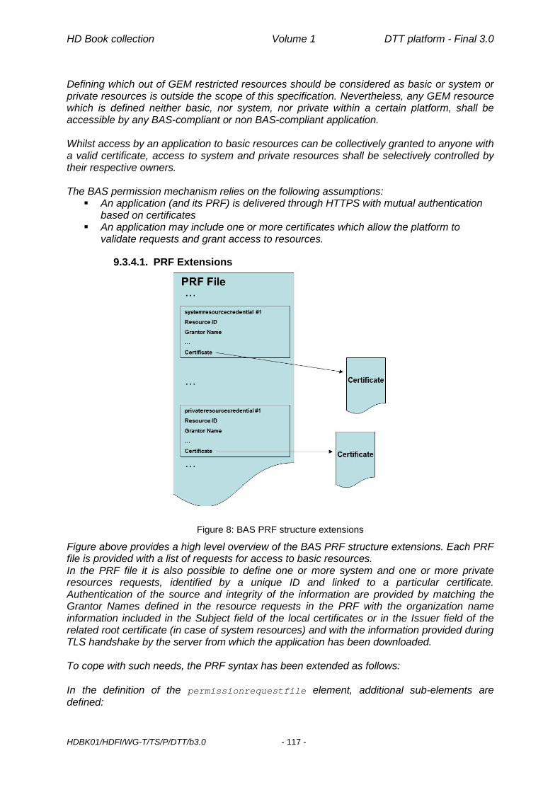
HD Book collection Volume 1 DTT platform - Final 3.0
HDBK01/HDFI/WG-T/TS/P/DTT/b3.0 - 117 -
Defining which out of GEM restricted resources should be considered as basic or system or private resources is outside the scope of this specification. Nevertheless, any GEM resource which is defined neither basic, nor system, nor private within a certain platform, shall be accessible by any BAS-compliant or non BAS-compliant application. Whilst access by an application to basic resources can be collectively granted to anyone with a valid certificate, access to system and private resources shall be selectively controlled by their respective owners. The BAS permission mechanism relies on the following assumptions: An application (and its PRF) is delivered through HTTPS with mutual authentication
based on certificates An application may include one or more certificates which allow the platform to
validate requests and grant access to resources.
9.3.4.1. PRF Extensions
Figure 8: BAS PRF structure extensions
Figure above provides a high level overview of the BAS PRF structure extensions. Each PRF file is provided with a list of requests for access to basic resources. In the PRF file it is also possible to define one or more system and one or more private resources requests, identified by a unique ID and linked to a particular certificate. Authentication of the source and integrity of the information are provided by matching the Grantor Names defined in the resource requests in the PRF with the organization name information included in the Subject field of the local certificates or in the Issuer field of the related root certificate (in case of system resources) and with the information provided during TLS handshake by the server from which the application has been downloaded. To cope with such needs, the PRF syntax has been extended as follows: In the definition of the permissionrequestfile element, additional sub-elements are defined:
HD Book collection Volume 1 DTT platform - Final 3.0
HDBK01/HDFI/WG-T/TS/P/DTT/b3.0 - 118 -
systemresourcecredential*, privateresourcecredential* The systemresourcecredential is the extensible mechanism by which an implementation can grant to an application the rights to access specific system resources. Each specific system resource is defined as a separate element in the PRF file. The privateresourcecredential is the extensible mechanism by which an implementation can grant to an application the rights to access specific private resources. Each specific private resource is defined as a separate element in the PRF file. A particular profile of the BAS specification can further restrict access to resources already defined in GEM by defining them as system or private resources. In this case, even if the PRF provides the related element and attributes for the resource (e.g: Provider Management etc…) according to the GEM PRF syntax, access to that resource can be granted only if the related systemresourcecredential or privateresourcecredential element is present in the PRF and the requested validation procedure is completed successfully. The following additional section in the PRF is defined: <!-- ..................... new elements in BAS ................ --> <!ELEMENT systemresourcecredential (grantorname, expirationdate, certchainfileid)> <!ATTLIST systemresourcecredential id CDATA #REQUIRED value (true | false) "false" > <!ELEMENT grantorname EMPTY> <!ATTLIST grantorname name CDATA #REQUIRED > <!ELEMENT privateresourcecredential (grantorname, expirationdate, certchainfileid)> <!ATTLIST privateresourcecredential id CDATA #REQUIRED value (true | false) "false" > The following section provides more information about the different elements defined above: id: The hexadecimal string identifier for the system or private resource. value: When the boolean value is set to true, this means that the application can access the system or private resource identified by the id string. When set to false the application has the same rights as an unprivileged application. The default rights can be overridden by the permission request file as described above. grantorname: This element contains in the attribute name, the string of the organization name identifying the grantor organization for a system or private resource. expirationdate and certchainfileid elements are defined in GEM’s PRF (Permission Request File) [62]. Rules for localizing the certificate indicated by certchainfileid and to constructing the certchainfileid itself are those already described in GEM. See Annex N for an example of PRF file.
9.3.4.2. Request validation procedures The BAS mechanism grants access to receiver’s resources performing a request validation procedure which involves: Server certificate acquired by the device during TLS handshake when application is
downloaded.

HD Book collection Volume 1 DTT platform - Final 3.0
HDBK01/HDFI/WG-T/TS/P/DTT/b3.0 - 119 -
Certificate pointed to by certchainfileid in systemresourcecredential elements (if access to System Resources is requested).
Certificate pointed to by certchainfileid in privateresourcecredential elements(if access to Private Resources is requested).
The certificate chain file pointed by certchainfileid might actually work for any application by an organization or just for some particular application. Specification of the latter case is outside the scope of this document. To correctly authenticate any of the certificates (files) mentioned, there must be a valid “chain” of certificates from the leaf certificate to a trusted root certificate (trust anchor) installed on the receiver. The BAS mechanism also requires that organization names used in the certificates provided for TLS sessions by the server and for application resource requests would match. Access to basic resources is granted by default, if requested in the PRF, to anyone with a valid certificate, validated through TLS handshake during the application download process. To validate a system resource request, the grantorname in the systemresourcecredential shall match the organizationName contained in the Issuer field of the root certificate for the certificate chain file pointed by certchainfileid. The organizationName in the Subject field of the certificate provided during TLS handshake by the server from which the application has been downloaded shall match organizationName in the Subject field of the leaf certificate in the certificate chain file pointed to by certchainfileid of systemresourcecredential. To validate a private resource request, the grantorname in the privateresourcecredential shall match the organizationName contained in the Subject field of the leaf certificate for access to be granted. The organizationName in the Subject field of the certificate provided during TLS handshake by the server from which the application has been downloaded shall match the organizationName in the Subject field of the leaf certificate in the certificate chain file pointed to by certchainfileid of privateresourcecredential. It must be noted that system and private resources shouldn’t be necessarily defined in a public specification. A service platform operator or a single company may define its own system/private resource and share the definition with potential implementers inside a proprietary document provided that clash of resource ids is avoided through some centralized registry. Compliant implementations will maintain a “white list” of system/private resources (IDs) and a list of organizations that are allowed to access them. The white list will also include, for each organization, in which namespace the related
certificate shall be validated (selecting the appropriate trust anchor). The namespace is the name of the issuer of the trust anchor to be used for the certificate validation procedure.
Implementations shall ensure that the trust anchors involved in the PRF certificate validation procedures are managed independently from other trust anchors available on the receivers (e.g.: used for internet browsing etc…). Certificates used for PRF validation must be kept in a dedicated certificate store, separated from those used for other purposes.
See Annex O for an example of system resource declaration and validation.

HD Book collection Volume 1 DTT platform - Final 3.0
HDBK01/HDFI/WG-T/TS/P/DTT/b3.0 - 120 -
Access by unprivileged applications to any system resource is forbidden by default. Any implementation supporting a particular system resource included in a PRF will grant access to it by a BAS signalled application, only if the following conditions are met:
1. the PRF has been successfully validated (i.e. the file has been downloaded along with the application from a server with a valid TLS certificate and orgid/appid in the PRF header do match organization_id/application_id in the AIT)
2. the requested system resource, as identified by id field in the systemsourcefilecredential element, is supported by the implementation and the related value field has been set to true
3. the certificate pointed by the certchainfileid element is authenticated 4. the grantorname of the requested system resource does match the
organizationName of the Issuer field in the root certificate for the certificate chain file pointed by the certchainfileid element
5. the organizationName of the Issuer field in the root certificate associated to the requested system resource does match the organizationName of one of the legitimate resource owners
6. the organizationName of the Subject field in the certificate associated to the requested system resource does match organizationName of the Subject field in the certificate provided during TLS handshake by the server from which the application has been downloaded
If either verification would fail access to that resource will be blocked. Access by unprivileged applications to any private resource is forbidden by default. Any implementation supporting a particular private resource included in a PRF will grant access to it by a BAS signalled application (see section 9.3.3), only if the following conditions are met:
1. the PRF has been successfully validated (the file has been downloaded along with the application from a server with a valid TLS certificate and orgid/appid in the PRF header do match organization_id/application_id in the AIT)
2. the requested private resource, as identified by id field in privateresourcefilecredential element, is supported by the implementation and the related value field has been set to true
3. the certificate pointed by the certchainfileid element is authenticated 4. the grantorname of the requested private resource does match the
organizationName of the Subject field in the certificate pointed by the certchainfileid element
5. the organizationName of the Subject field in the certificate associated to the requested private resource does match the organizationName of one of the legitimate resource owners
6. the organizationName of the Subject field in the certificate associated to the requested private resource does match the organizationName of the Subject field in the certificate provided during TLS handshake by the server from which the application has been downloaded
If either verification would fail access to that resource will be blocked.
9.3.5. Impact of BAS on broadcast applications For consistency with restrictions introduced by BAS for broadband applications to access certain GEM resources, system and private resources defined on a particular platform will be granted only to broadcast applications signaled as signed (application_id ranging from 0x4000 to 0x7fff) with a proper PRF and related valid certificate.

HD Book collection Volume 1 DTT platform - Final 3.0
HDBK01/HDFI/WG-T/TS/P/DTT/b3.0 - 121 -
9.4. Certificate Management Even though certificates available at client side (which ones, how many) are outside the scope of this specification, their management (installation of root certificates and revocation of leaf certificates) is crucial for BAS to work harmoniously and consistently. For this reason some requirements in this area are specified in the following. First very basic requirement is that certificates SHALL be compliant to the X.509 Certificate profile defined in IETF RFC 2459 [64] as specified in GEM [62].
9.4.1. Certificate Revocation In order to revoke server certificates 2 different solutions can be alternatively pursued for BAS:
1. Certificate Revocation List (CRL) as defined in IETF RFC 2459 [64]. CRLs can be downloaded over HTTP or HTTPS. If HTTPS is used, the mutual authentication of the peers is required.
2. Online Certificate Status Protocol (OCSP) as defined in IETF RFC 2560 [65]
The solutions listed above are both defined as OPTIONAL in BAS. It is expected that a BAS profile specification for a particular platform provider will mandate only one solution.
9.4.2. Root certificate management New root certificate(s) can be installed on a receiver in the field via
1. a new software image provided by the manufacturer. Software update may be performed OTA or through broadband network download.
2. Root Certificate Management Message (RCMM) as specified by GEM in Section 12.9.2 [62].
In the scope of BAS RCMM::SignatureInfo contains only one signature, i.e. a BAS-compliant receiver SHALL process only a single RCMM signature in the SignatureInfo structure (encrypted with a non-revoked root certificate). It means that nextNbOfSignatures is assumed to be always at most 1; if higher than 1, the value is ignored and assumed to be 1. BAS-compliant implementations SHALL support RCMM with the above constraint. RCMM shall operate only on the BAS certificate store, i.e. only RCMMs signed by a CA whose trust anchor is already present in the BAS certificate store will succeed in installing new root certificates in the BAS certificate store itself. Successful RCMM SHALL modify the receiver white list as follows:
• Any resource granted by the Issuer who has signed an RCMM adding a new trust anchor will be granted by the Issuer of the latter too
• Any entry in the white list referring to an Issuer whose trust anchor has been removed with a valid RCMM will be removed too
9.4.3. Certificate store exposure To allow test applications checking that no rogue root certificate is being used for BAS purposes, the BAS certificate store SHALL be accessible to MHP applications as a file in read-only filesystem, whose path SHALL be stored in a dedicated java system property named system.BAS.keystore. Such a certificate store SHALL NOT be password-protected.

HD Book collection Volume 1 DTT platform - Final 3.0
HDBK01/HDFI/WG-T/TS/P/DTT/b3.0 - 122 -
9.4.4. White list exposure To allow test applications checking that no rogue white list is being used for BAS purposes and that changes driven by RCMM are duly applied, the BAS white list SHALL be accessible to MHP applications as an XML file in read-only filesystem, whose path SHALL be stored in a dedicated java system property named system.BAS.whitelist. Such a file SHALL NOT be password-protected. The XML schema used for such file and an example can be found in Annex P.

HD Book collection Volume 1 DTT platform - Final 3.0
HDBK01/HDFI/WG-T/TS/P/DTT/b3.0 - 123 -
10. Accessories and Setup Receivers must be both easy to install and use. An existing viewer of analogue services needs to be able to complete a basic digital installation, i.e. just for viewing, using only what has been supplied with the receiver. In addition, on-screen information must be provided in a clear and consistent manner both to aid installation and (if required) to enable an easy dialogue with any support staff, e.g. call-centre
10.1. Receiver Accessories The manual should contain at least the following information:
1. Advice on the verification and eventual adaptation of reception equipment 2. The modes of connection of other peripheral appliances (TV, VCR, DVD, other STB) 3. Mode of connection to the broadband network 4. Set up and tuning of the receiver 5. Description of the functions of the remote control keys 6. Options and accessories (e.g. Infra-red Keyboard, etc…) 7. Troubleshooting 8. Information on a call centre number to resolve connection problems.
Accessory Presence 1 Power Cable Mandatory
Handbook in Italian language Mandatory
Table 40: Accessories
10.2. Power Supply / Voltage 220V AC + 15%; 50 + 2 Hz (Low Voltage recommendation 73/23/CEE e 93/68/CEE. Law n° 971/1977).
10.3. Low-power mode In order for receivers supporting a low-power standby feature, based on mandatory or voluntary EU ecodesign requirements, to meet operators’ needs (e.g. rights refresh for Pay TV services, spot software upgrade campaigns), the following recommendations/constraints apply:
1. It SHOULD be possible disabling/enabling low-power standby mode through a dedicated menu option
2. before entering low-power standby mode receivers SHALL perform, if currently enabled, automatic channel list update and software upgrade
3. transition from normal to low-power stand-by mode SHOULD take at least 1 hour 4. low-power standby mode SHOULD NOT last longer than 23 consecutive hours
before normal stand-by is entered; after house keeping (point 2) is performed and proper transition time waited (point 3), low-power standby mode will be entered again.

Page intentionally left blank
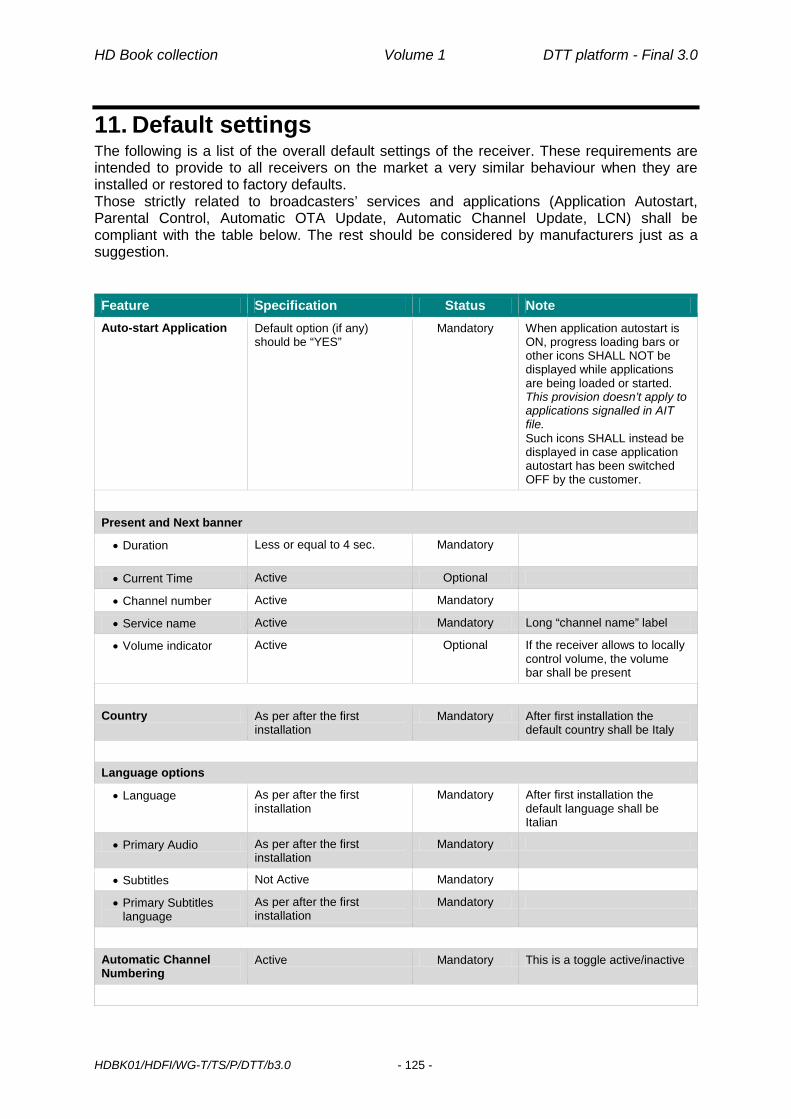
HD Book collection Volume 1 DTT platform - Final 3.0
HDBK01/HDFI/WG-T/TS/P/DTT/b3.0 - 125 -
11. Default settings The following is a list of the overall default settings of the receiver. These requirements are intended to provide to all receivers on the market a very similar behaviour when they are installed or restored to factory defaults. Those strictly related to broadcasters’ services and applications (Application Autostart, Parental Control, Automatic OTA Update, Automatic Channel Update, LCN) shall be compliant with the table below. The rest should be considered by manufacturers just as a suggestion. Feature Specification Status Note Auto-start Application Default option (if any)
should be “YES” Mandatory When application autostart is
ON, progress loading bars or other icons SHALL NOT be displayed while applications are being loaded or started. This provision doesn’t apply to applications signalled in AIT file. Such icons SHALL instead be displayed in case application autostart has been switched OFF by the customer.
Present and Next banner
• Duration Less or equal to 4 sec. Mandatory
• Current Time Active Optional
• Channel number Active Mandatory
• Service name Active Mandatory Long “channel name” label
• Volume indicator Active Optional If the receiver allows to locally control volume, the volume bar shall be present
Country As per after the first installation
Mandatory After first installation the default country shall be Italy
Language options
• Language As per after the first installation
Mandatory After first installation the default language shall be Italian
• Primary Audio As per after the first installation
Mandatory
• Subtitles Not Active Mandatory
• Primary Subtitles language
As per after the first installation
Mandatory
Automatic Channel Numbering
Active Mandatory This is a toggle active/inactive

HD Book collection Volume 1 DTT platform - Final 3.0
HDBK01/HDFI/WG-T/TS/P/DTT/b3.0 - 126 -
Feature Specification Status Note TV settings
• Screen Format 16:9 Mandatory
• HDMI output format As per after the first installation
Mandatory
• TV SCART output RGB Mandatory
• VCR SCART output CVBS Mandatory when available
• 3D Display Y/N Mandatory Information gathered from HDMI VSDB overrides any manual setting
Parental Control settings
PIN protected events PIN shall be asked for any event with rating value equal or greater than 18 years in Parental_rating_descriptor
Mandatory
Automatic software upgrade
In Stand by mode Active* Mandatory
In Operate mode Active* Optional
Time 4:00 am Mandatory
Repetition Daily Mandatory
Automatic channel list update
..in Stand by mode Active Mandatory
..in Operate mode Not Active Optional
Time 4:30 am Mandatory
Repetition Daily Mandatory
Table 41: Default settings summary table
* The automatic software upgrade shall be ON to avoid users missing the necessary upgrades. However, if an automatic upgrade feature is present, this must be clearly indicated to the user so that, at set up, he/she may choose to deactivate it. In that case, the information on availability of new software for the receiver shall be presented to the user.

Annexes

Page intentionally left blank

HD Book collection Volume 1 DTT platform - Final 3.0
HDBK01/HDFI/WG-T/TS/P/DTT/b3.0 - 129 -
A DVB-T2 Performance Tables17 A.1 FEF and Auxiliary streams To test that FEFs do not cause malfunctions the following T2+FEF test signal shall be generated and input to the receiver, with FEF power same as T2 signal and no added noise. The receiver should be able to receive this signal with no errors in the displayed video for PLP#0.
Property Value
Overall FFTSIZE 32k GI 1/16 Lf 62 SISO/MISO SISO PAPR TR-PAPR Frames per superframe (NT2) 6 Bandwidth 8MHz Extended Bandwidth Mode Yes Pilot Pattern PP4 L1 Modulation 64QAM FEF Type 0 FEF Length (samples) 588000 FEF Interval 6 FEF P1: S1 Value 2 FEF P1: S2 Value 1 L1 Repetition 0 PLP #0 Type 1 Modulation 256QAM Rate 3/5 FEC Type 64800 Rotated QAM Yes FEC blocks per interleaving frame 200 TI blocks per frame (N_TI) 3 T2 frames per Interleaving Frame (P_I) 1 Frame Interval (I_JUMP) 1 Type of time-interleaving 0 Time Interleaving length 3
Table 42: FEF test signal
To test that the presence of Auxiliary streams does not cause malfunctions the following test signal shall be generated and input to the receiver, with no added noise. The receiver, with Auxiliary streams enabled, should be able to receive this signal with no errors in the displayed video for PLP#0. 17 All data specified in this Annex are preliminary because DVB-T2 experience in real operations is very limited, especially in case of SFN

HD Book collection Volume 1 DTT platform - Final 3.0
HDBK01/HDFI/WG-T/TS/P/DTT/b3.0 - 130 -
Property Value
Overall FFTSIZE 32k GI 1/16 Lf 62 SISO/MISO SISO PAPR TR-PAPR Frames per superframe (NT2) 6 Bandwidth 8MHz Extended Bandwidth Mode Yes Pilot Pattern PP4 L1 Modulation 64QAM FEFs Not used L1 Repetition 0 PLP #0 Type 1 Modulation 256QAM Rate 3/5 FEC Type 64800 Rotated QAM Yes FEC blocks per interleaving frame 200 TI blocks per frame (N_TI) 3 T2 frames per Interleaving Frame (P_I) 1 Frame Interval (I_JUMP) 1 Type of time-interleaving 0 Time Interleaving length 3
Table 43: Auxiliary streams test signal
A.2 C/N Performance Examples of C/N values and sensitivity are given in the following tables. AWGN and “0dB echo” C/N calculations are based on NorDig [78] and EBU [76] assumptions for implementation losses. Ricean and Rayleigh C/N calculations are based on EBU assumptions [76].
Modulation Code rate
C/N performance (dB) 32KE PP2 C/N (dB) 32KE PP2 Sensitivity
8MHz, NF=6, 290K (dBm), Px=-33dBc Profile1 Gaussian (AWGN)
Profile2 (Ricean)
F1
Profile3 (Rayleigh)
P1
Profile4 (0dB echo)
Profile1 Gaussian (AWGN)
Profile2 (Ricean)
F1
Profile3 (Rayleigh)
P1
Profile4 (0dB echo)
QPSK 1/2 3.5 3.7 4.5 5.2 -95.6 -95.4 -94.6 -93.9 QPSK 3/5 4.7 4.9 6.0 6.8 -94.4 -94.2 -93.1 -92.3 QPSK 2/3 5.6 5.9 7.4 8.4 -93.5 -93.2 -91.7 -90.7 QPSK 3/4 6.6 6.9 8.7 9.8 -92.5 -92.2 -90.4 -89.3 QPSK 4/5 7.2 7.6 9.6 10.9 -91.9 -91.5 -89.5 -88.2 QPSK 5/6 7.7 8.1 10.4 12.0 -91.4 -91.0 -88.7 -87.1 16 QAM 1/2 8.7 8.9 10.2 10.9 -90.4 -90.2 -88.9 -88.2 16 QAM 3/5 10.1 10.3 11.8 12.7 -89.0 -88.8 -87.3 -86.4 16 QAM 2/3 11.4 11.6 13.3 14.3 -87.7 -87.5 -85.8 -84.7 16 QAM 3/4 12.5 12.9 14.9 16.3 -86.6 -86.2 -84.1 -82.8

HD Book collection Volume 1 DTT platform - Final 3.0
HDBK01/HDFI/WG-T/TS/P/DTT/b3.0 - 131 -
Modulation Code rate
C/N performance (dB) 32KE PP2 C/N (dB) 32KE PP2 Sensitivity
8MHz, NF=6, 290K (dBm), Px=-33dBc Profile1 Gaussian (AWGN)
Profile2 (Ricean)
F1
Profile3 (Rayleigh)
P1
Profile4 (0dB echo)
Profile1 Gaussian (AWGN)
Profile2 (Ricean)
F1
Profile3 (Rayleigh)
P1
Profile4 (0dB echo)
16 QAM 4/5 13.3 13.7 16.2 17.8 -85.8 -85.4 -82.9 -81.3 16 QAM 5/6 13.8 14.2 17.0 18.9 -85.3 -84.8 -82.1 -80.1 64QAM 1/2 13.0 13.3 15.0 16.0 -86.1 -85.8 -84.0 -83.1 64QAM 3/5 14.8 15.1 16.9 18.0 -84.2 -83.9 -82.2 -81.1 64QAM 2/3 16.2 16.5 18.3 19.7 -82.9 -82.6 -80.8 -79.4 64QAM 3/4 17.7 18.0 20.4 22.0 -81.4 -81.1 -78.7 -77.1 64QAM 4/5 18.7 19.2 22.0 24.0 -80.3 -79.8 -77.1 -75.1 64QAM 5/6 19.4 19.8 23.0 25.5 -79.7 -79.3 -76.1 -73.6 256 QAM 1/2 17.0 17.4 19.5 20.6 -82.1 -81.7 -79.6 -78.5 256 QAM 3/5 19.4 19.6 21.7 23.1 -79.7 -79.5 -77.4 -76.0 256 QAM 2/3 20.8 21.1 23.3 25.1 -78.2 -77.9 -75.8 -73.9 256 QAM 3/4 22.9 23.2 25.8 28.0 -76.2 -75.9 -73.2 -71.1 256 QAM 4/5 24.3 24.8 28.0 30.8 -74.8 -74.3 -71.1 -68.2 256 QAM 5/6 25.1 25.6 29.5 33.6 -73.9 -73.5 -69.6 -65.5
Table 44: Example of maximum required C/N and sensitivity for QEF reception at TS output (PP2 and FFT size 32KE)
Modulation Code rate
C/N performance (dB) 32KE PP4 C/N (dB) 32KE PP4 Sensitivity 8MHz, NF=6, 290K
(dBm), Px=-33dBc Profile1 Gaussian (AWGN)
Profile2 (Ricean)
F1
Profile3 (Rayleigh)
P1
Profile4 (0dB echo)
Profile1 Gaussian (AWGN)
Profile2 (Ricean)
F1
Profile3 (Rayeigh)
P1
Profile4 (0dB echo)
QPSK 1/2 3.1 3.3 4.1 4.8 -96.0 -95.8 -95.0 -94.3 QPSK 3/5 4.3 4.5 5.6 6.4 -94.8 -94.6 -93.5 -92.7 QPSK 2/3 5.2 5.5 7.0 8.0 -93.9 -93.6 -92.1 -91.1 QPSK 3/4 6.2 6.5 8.3 9.4 -92.9 -92.6 -90.8 -89.7 QPSK 4/5 6.8 7.2 9.2 10.5 -92.3 -91.9 -89.9 -88.6 QPSK 5/6 7.3 7.7 10.0 11.6 -91.8 -91.4 -89.1 -87.5 16 QAM 1/2 8.3 8.5 9.8 10.5 -90.8 -90.6 -89.3 -88.6 16 QAM 3/5 9.7 9.9 11.4 12.3 -89.4 -89.2 -87.7 -86.8 16 QAM 2/3 11.0 11.2 12.9 13.9 -88.1 -87.9 -86.2 -85.2 16 QAM 3/4 12.1 12.5 14.5 15.8 -87.0 -86.6 -84.6 -83.2 16 QAM 4/5 12.9 13.3 15.7 17.4 -86.2 -85.8 -83.3 -81.7 16 QAM 5/6 13.4 13.8 16.5 18.5 -85.7 -85.3 -82.5 -80.6 64QAM 1/2 12.6 12.9 14.6 15.5 -86.5 -86.2 -84.5 -83.5 64QAM 3/5 14.4 14.7 16.4 17.6 -84.7 -84.4 -82.6 -81.5 64QAM 2/3 15.7 16.0 17.9 19.2 -83.3 -83.0 -81.2 -79.8 64QAM 3/4 17.3 17.6 20.0 21.6 -81.8 -81.5 -79.1 -77.5 64QAM 4/5 18.3 18.8 21.6 23.5 -80.8 -80.3 -77.5 -75.6 64QAM 5/6 18.9 19.3 22.5 25.0 -80.2 -79.7 -76.6 -74.1 256 QAM 1/2 16.5 17.0 19.0 20.2 -82.5 -82.1 -80.1 -78.9 256 QAM 3/5 18.9 19.1 21.2 22.6 -80.2 -79.9 -77.8 -76.4 256 QAM 2/3 20.4 20.7 22.9 24.6 -78.7 -78.4 -76.2 -74.4 256 QAM 3/4 22.4 22.7 25.3 27.4 -76.7 -76.3 -73.7 -71.7 256 QAM 4/5 23.8 24.3 27.4 30.2 -75.2 -74.8 -71.7 -68.9 256 QAM 5/6 24.6 25.1 28.9 32.7 -74.4 -74.0 -70.2 -66.3
Table 45: Example of maximum required C/N and sensitivity for QEF reception at TS output (PP4 and FFT size 32KE)
Modulation Code rate
C/N performance (dB) 32KE PP4 C/N (dB) 32KE PP4 Sensitivity 8MHz, NF=6, 290K
(dBm), Px=-33dBc Profile1 Gaussian (AWGN)
Profile2 (Ricean)
F1
Profile3 (Rayleigh)
P1
Profile4 (0dB echo)
Profile1 Gaussian (AWGN)
Profile2 (Ricean)
F1
Profile3 (Rayeigh)
P1
Profile4 (0dB echo)
QPSK 1/2 2.4 2.6 3.4 4.1 -96.6 -96.4 -95.6 -94.9 QPSK 3/5 3.6 3.8 4.9 5.7 -95.4 -95.2 -94.1 -93.3

HD Book collection Volume 1 DTT platform - Final 3.0
HDBK01/HDFI/WG-T/TS/P/DTT/b3.0 - 132 -
Modulation Code rate
C/N performance (dB) 32KE PP4 C/N (dB) 32KE PP4 Sensitivity 8MHz, NF=6, 290K
(dBm), Px=-33dBc Profile1 Gaussian (AWGN)
Profile2 (Ricean)
F1
Profile3 (Rayleigh)
P1
Profile4 (0dB echo)
Profile1 Gaussian (AWGN)
Profile2 (Ricean)
F1
Profile3 (Rayeigh)
P1
Profile4 (0dB echo)
QPSK 2/3 4.5 4.8 6.3 7.3 -94.5 -94.2 -92.7 -91.7 QPSK 3/4 5.5 5.8 7.6 8.7 -93.5 -93.2 -91.4 -90.3 QPSK 4/5 6.1 6.5 8.5 9.9 -92.9 -92.5 -90.5 -89.2 QPSK 5/6 6.6 7.0 9.3 11.0 -92.4 -92.0 -89.7 -88.1 16 QAM 1/2 7.6 7.8 9.1 9.9 -91.4 -91.2 -89.9 -89.2 16 QAM 3/5 9.0 9.2 10.8 11.7 -90.0 -89.8 -88.3 -87.4 16 QAM 2/3 10.4 10.6 12.3 13.3 -88.7 -88.5 -86.8 -85.8 16 QAM 3/4 11.5 11.9 13.9 15.2 -87.6 -87.2 -85.2 -83.9 16 QAM 4/5 12.3 12.7 15.1 16.7 -86.8 -86.4 -84.0 -82.3 16 QAM 5/6 12.8 13.2 15.9 17.9 -86.3 -85.9 -83.2 -81.2 64QAM 1/2 12.0 12.3 14.0 14.9 -87.1 -86.8 -85.1 -84.2 64QAM 3/5 13.8 14.1 15.8 16.9 -85.3 -85.0 -83.3 -82.1 64QAM 2/3 15.1 15.4 17.2 18.6 -84.0 -83.7 -81.8 -80.5 64QAM 3/4 16.6 16.9 19.3 20.9 -82.4 -82.1 -79.8 -78.2 64QAM 4/5 17.7 18.2 20.9 22.8 -81.4 -80.9 -78.2 -76.2 64QAM 5/6 18.3 18.7 21.9 24.3 -80.8 -80.4 -77.2 -74.8 256 QAM 1/2 15.9 16.3 18.4 19.5 -83.2 -82.8 -80.7 -79.6 256 QAM 3/5 18.3 18.5 20.6 22.0 -80.8 -80.6 -78.5 -77.1 256 QAM 2/3 19.7 20.0 22.2 23.9 -79.3 -79.0 -76.9 -75.1 256 QAM 3/4 21.7 22.1 24.6 26.6 -77.3 -77.0 -74.5 -72.4 256 QAM 4/5 23.2 23.6 26.6 29.3 -75.9 -75.5 -72.4 -69.8 256 QAM 5/6 23.9 24.4 28.0 31.6 -75.1 -74.7 -71.0 -67.5
Table 46: Example of maximum required C/N and sensitivity for QEF reception at TS output (PP7 and FFT size 32KE)
Note 1: Values do not include any possible additional Implementation Loss for Ricean (e.g. 0.5dB) and Rayleigh (e.g. 0.75dB) that can be adopted as “safety margin” for receiver conformance purposes only. It’s expected that this possible additional margin shall be included into the typical (e.g. 1 dB) “measurement error margin” that is always admitted for receiver conformance purposes.
Note 2: Values of Sensitivity are calculated under the assumption NF= 6dB Note 3: Values of sensitivity for 32KN (8MHz BW) can be obtained taking into account
the difference of the signal BW between the two cases (7.77 MHz vs. 7.61 MHz), giving for 32KN a reduction of approximately 0.1 dB with respect to the case of 32KE. Values of sensitivity in case of 7MHz BW can be obtained accordingly to the previous rule (6.80 MHz for 32KE and 6.66 MHz for 32KN) giving a value of approx. 0.6 dB less than the case of 8MHz BW.
Note 4: Receivers shall be capable of QEF reception for all the DVB-T2 possible modes (as from the list of “Mandatory requirement”) listed in this version of HD-Book. Additional values for the C/N Performance (e.g. valid for PP1) can be obtained using similar assumptions to those in [76] and [78].
Note 5: C/N values in the Tables can be used for 32KN FFT size and also for other FFT sizes e.g. 16K. Guard Interval does not influence C/N and, therefore, sensitivity.
Profile 1: Gaussian noise (N) is applied together with the wanted carrier (C) in a signal
bandwidth of a DVB-T2 signal. No echo is applied. Profile 2: The Ricean channel is defined according to the following table (derived from
Table B.1 of [13]). Path #14 is omitted. Profile 3: The Rayleigh channel definition is derived from the following table as well by
removing path #0 and re-normalising amplitude values.
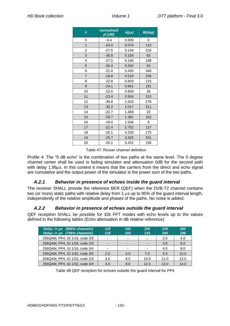
HD Book collection Volume 1 DTT platform - Final 3.0
HDBK01/HDFI/WG-T/TS/P/DTT/b3.0 - 133 -
# normalised ρi [dB] τi(µs) θi(deg)
0 -0.4 0.000 0 1 -24.0 0.074 122 2 -27.5 0.144 226 3 -36.8 0.154 63 4 -27.5 0.194 198 5 -26.4 0.204 63 6 -21.6 0.430 340 7 -18.8 0.519 336 8 -22.8 0.603 215 9 -24.1 0.641 191 10 -22.6 0.849 36 11 -23.4 0.924 210 12 -35.8 1.003 278 13 -35.2 1.017 311 14 -22.7 1.369 23 15 -29.7 1.381 162 16 -19.0 1.936 9 17 -21.4 2.752 127 18 -20.1 3.229 175 19 -25.7 3.325 331 20 -26.1 5.422 196
Table 47: Ricean channel definition
Profile 4: The “0 dB echo” is the combination of two paths at the same level. The 0 degree channel center shall be used in fading simulator and attenuation 0dB for the second path with delay 1.95µs. In this context it means that the carriers from the direct and echo signal are cumulative and the output power of the simulator is the power sum of the two paths.
A.2.1 Behavior in presence of echoes inside the guard interval The receiver SHALL provide the reference BER (QEF) when the DVB-T2 channel contains two (or more) static paths with relative delay from 1 µs up to 95% of the guard interval length, independently of the relative amplitude and phases of the paths. No noise is added.
A.2.2 Behavior in presence of echoes outside the guard interval QEF reception SHALL be possible for 32k FFT modes with echo levels up to the values defined in the following tables (Echo attenuation in dB relative reference).
Delay -/+ µs (8MHz channels) 120 150 200 230 260 Delay -/+ µs (7MHz channels) 135 165 215 266 298 256QAM, PP4, GI 1/16, code 3/5 - - - 2.0 4.0 256QAM, PP4, GI 1/16, code 2/3 - - - 3.0 6.0 256QAM, PP4, GI 1/16, code 3/4 - - - 4.0 8.0 256QAM, PP4, GI 1/32, code 3/5 2.0 4.0 7.0 9.0 10.0 256QAM, PP4, GI 1/32, code 2/3 3.0 6.0 10.0 11.0 12.0 256QAM, PP4, GI 1/32, code 3/4 4.0 8.0 12.0 13.0 14.0
Table 48 QEF reception for echoes outside the guard interval for PP4

HD Book collection Volume 1 DTT platform - Final 3.0
HDBK01/HDFI/WG-T/TS/P/DTT/b3.0 - 134 -
Delay -/+ µs (7MHz channels) 266 298 400 512 608 256QAM, PP2, GI 1/16, code 3/5 2.0 4.0 9.0 11.0 12.0
256QAM, PP2, GI 1/16, code 2/3 3.0 6.0 11.0 14.0 15.0
256QAM, PP2, GI 1/16, code 3/4 4.0 8.0 14.0 16.0 18.0
Table 49 QEF reception for echoes outside the guard interval for PP2, GI 1/16, 7MHz
Delay -/+ µs (8MHz channels) 120 150 200 230 260 Delay -/+ µs (7MHz channels) 135 165 215 266 298 256QAM, PP2, GI 1/8, code 3/5 3.5 5.5 7.0 8.0 8.5 256QAM, PP2, GI 1/8, code 2/3 5.0 7.0 8.5 9.5 10.0 256QAM, PP2, GI 1/8, code 3/4 7.0 9.0 10.5 11.5 12.0
Table 50 QEF reception for echoes outside the guard interval for PP2, GI 1/8
As a non-mandatory indication of typical receiver performance, QEF reception in case of three SFN static paths inside the guard interval and one SFN static path outside the guard interval should be possible for the T2 modes and echo profiles below: • 8MHz, FFT 32K, 256QAM, CR 2/3, PP4, GI 1/16
Path (tap) Delay (µs) Relative attenuation (dB) 1 (useful) 0 6 2 (useful) 50 0 (reference -60 dBm) 3 (useful) 180 10 4 (interference) 270 20.7
Table 51: Test set-up (PP4) for pre-echoes and echoes outside the guard interval (informative)
• 8MHz, FFT 32K, 256QAM, CR 2/3, PP2, GI 1/8
Path (tap) Delay (µs) Relative attenuation (dB) 1 (useful) 0 6 2 (useful) 50 0 (reference -60 dBm) 3 (useful) 180 10 4 (interference) 550 21.1
Table 52: Test set-up (PP2) for pre-echoes and echoes outside the guard interval (informative)
A.2.3 Behavior in presence of co-channel interference QEF reception shall be possible in the presence of a DVB-T/T2 co-channel interferer with a C/I level according to column “C/N Ricean” (profile 2) in Table 48, Table 49 and Table 50 when the interference is uncorrelated with the wanted signal. As a non-mandatory indication of typical receiver performance, in the case of a co-channel interference where the interferer may be correlated with the wanted DVB-T2 signal symbol timing and pilot pattern (e.g. inside an SFN), an additional margin of 1dB should be added.
A.2.4 Behavior in presence of digital signal in other channels Reference is the NorDig Unified specification ver. 2.5.1 [78], chapter 3.4.10.6.1 “Immunity to DVB-T/T2 signals in other channels”.
A.2.5 Behavior in presence of co-channel analogue signals Reference is the NorDig Unified ver. 2.4 [56], chapter 3.4.10.8 “Immunity to Co-Channel Interference from Analogue TV signals”.

HD Book collection Volume 1 DTT platform - Final 3.0
HDBK01/HDFI/WG-T/TS/P/DTT/b3.0 - 135 -
The receiver shall perform better than specified in Table 53 when a 8MHz DVB-T2 signal is exposed to interference from a co-channel G/PAL signal including video with teletext, an FM sound and a NICAM sub carrier. The level of the FM sound relative to the vision carrier is -13 dB. The level of the NICAM signal relative to the vision carrier is -20 dB.
Constellation 256 QAM Code rate 3/5 2/3 3/4 C/I 3 dB 5 dB 7 dB
Table 53 Carrier to Interference, C/I (dB) for QEF reception, when DVB-T2 signal is interfered with by an analogue TV carrier.
A.3 List of some DVB-T2 modes for different types of networks and receiving conditions
Table 54 shows a list of suitable T2 modes for a number of different network configurations and receiving conditions. It represents only a small sample of all the T2 modes that are possible. The intent is to give some examples, without limiting the possibility to adopt different T2 modes. Being the exact Bit-Rate of these modes subject to the choice of other parameters like, e.g., Lf and L1mod (and the combination of the PLPs in case of multiple PLP), all the values in the table are rounded and given only as an indicative value. Type Very
Large SFN
Very Large SFN
Large SFN-MISO
Large SFN
Local SFN
MFN Portable Mobile Fixed/ Portable
Fixed/Mobile
Single PLP Multiple PLP
T2 Base/Lite
Examples 1 2 3 4 5 6 7 8 9 10
FFT 32K 32K 32K 32K 32K 32K 16k 16k 32K 32K 8K
BW Extension (E/N) E N E E E N E E E E N
GI 1/8 1/8 19/256 1/16 1/32 1/128 1/4 1/4 1/8 1/16 1/4
GI duration (µs) 448 448 266 224 112 28 448 448 448 224 224
PP PP2 PP2 PP2 PP4 PP4 PP7 PP1 PP1 PP2 PP4 PP1
PLP1 Modulation 256QAM 256QAM 256QAM 256QAM 256QAM 256QAM 64QAM 16QAM 256QAM 256QAM QPSK
Rotation (R/NR) R NR R R R R NR R R R R
PLP1 Code rate 2/3 ¾ 2/3 2/3 2/3 3/5 3/4 1/2 3/4 3/4 2/3
PLP2 Modulation - - - - - - - - 16QAM - -
Rotation (R/NR) - - - - - - - - R
PLP2 Code rate - - - - - - - - 3/4 - -
SISO/MISO SISO SISO MISO SISO SISO SISO SISO SISO SISO SISO SISO
T2-Base/Lite T2-Base T2-Base T2-Base T2-Base T2-Base T2-Base T2-Base T2-Base T2-Base T2-Base T2-Lite
Bit-Rate (Mbit/s) 33 36 34 36 38 35 25 11 33 28 1,9
Table 54: List of some DVB-T2 Modes

Page intentionally left blank

HD Book collection Volume 1 DTT platform - Final 3.0
HDBK01/HDFI/WG-T/TS/P/DTT/b3.0 - 137 -
B Remote control B.1 The need for specifications Source : ETSI TR 102 308 V1.1.1 (2004-02) Technical Report User Group; User interoperability criteria • Specific recommendations for interoperability improvement
Specific claims for interoperability improvement have been identified in the following areas. Any progress on these issues is expected to improve the user confidence in standardization to ensure interoperability. Such examples can be taken as first implementation areas of the generic recommendations given in clause 6. These specific recommendations provided by particular users are generally supported by the vast majority of them but some of them have slightly different views on some particular ones (e.g. T2, T3, A3, HI).
• Terminals Rec#T1 Keyboard layout: The current terminals have different keyboard layout hence hindering easy use and service access. A standardized layout (same or "subset-compatible") should be used for the same service when applicable, particularly for "special" characters, like '+, '*', '#', etc. Tactile screens making feasible a customized keyboard layout could help to fulfil this requirement (VHE principle). When applicable, the pips for blind people should always be on the right places (e.g. number 5). UNICODE and ES 202 130 [26] should be used as far as possible to cope with the character sets of the various languages.
B.2 Keys and Key Events
B.2.1 The MHP minimum specification
Table 55: Minimum set of input events (G3)
NOTE 1: They are not guaranteed to be available to any one MHP application because another application running at the same time may have one of these events exclusively reserved. The application with focus (if any) always receives all of these events unless
Input event VK_0 to VK_9 VK_UP VK_DOWN VK_LEFT VK_RIGHT VK_ENTER VK_TELETEXT VK_COLORED_KEY_0 VK_COLORED_KEY_1 VK_COLORED_KEY_2 VK_COLORED_KEY_3

HD Book collection Volume 1 DTT platform - Final 3.0
HDBK01/HDFI/WG-T/TS/P/DTT/b3.0 - 138 -
another application within the same Service has requested and been granted exclusive access to one or more events. The process for event distribution for DVB-J applications is described in more detail in annex J, “(normative): DVB-J event API” on page 367. NOTE 2: The user input device for an MHP terminal may support more events than this however this is implementation dependent. If more events than this are supported, it is equally implementation dependent whether the additional events are sent to MHP applications or sent to the MHP navigator. Events which are always sent to the MHP navigator may not be visible at all to MHP applications. For example, an MHP receiver using a conventional remote control will probably have program up/program down keys which are only ever sent to the navigator and cause service selection when received there. NOTES included in ETSI 101 802
B.2.2 E-Book ver. 1 IEC 62216-1: “Digital terrestrial television receivers for the DVB-T system – Part 1: Baseline receiver specification” (E-Book, v.1) Remote controllable functions Description of the minimal functions of the remote control Function Comment
power on/stand-by
digital keys : 0,1, …, 9
Menu
up, down, right, left arrows display the television function menu
Validation validation of the choice
Back one level back in menu
quit, escape exit from the menu
Guide access to the EPG
Information display the current program information
Table 56: E-Book v.1.9
NB: This specification is no longer present in the E-Book v.1.9 or in the German specification D-Book minimum requirements.

HD Book collection Volume 1 DTT platform - Final 3.0
HDBK01/HDFI/WG-T/TS/P/DTT/b3.0 - 139 -
B.2.3 DTG UK
Figure 9: Remote Control Function Group
B.2.4 The CEI Specification Caratteristiche Specifica tecnica (minima) Spaziatura e dislocazione tasti Tasti critici distanziati
Tasti colore e sequenza 4 colori, conforme alle specifiche DVB, con l’ordine: rosso, verde, giallo e blu.
Scrittura di testi alfanumerici tipo GSM Utilizzo dei tasti alfanumerici da 0 a 9 (tipo cellulare)
Tasti previsti anche dalla TV analogica Tasti ‘Programma +’, ‘Programma –‘
Tasti ‘Volume +’, ‘Volume –‘, ‘Mute’
Tasto ‘AV’ (per input da SCART)
Tasto ‘Set-Up’
Tasti aggiuntivi Tasto ‘Info’ Attiva il navigatore
Tasto ‘iTv’ o ‘Interactive’
Attiva la lista dei servizi disponibili
Tasti freccia Pagina precedente/successiva e navigazione all’interno di programmi/servizi
Tasto ‘OK’ Lancio/conferma selezioni e impostazioni
Tasto ‘Exit’ Interruzione/uscita da selezione attiva
Tasti colore Scelta delle funzionalità disponibili all’interno dei programmi/servizi del broadcaster
Tasto ‘text’ Visualizzazione teletext qualora la decodifica dello stesso avvenga nel ricevitore.
Table 57: CEI Specification; CT 100, Progetto di Guida
The Cancel key is a key available to applications (programmable)
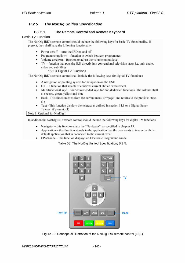
HD Book collection Volume 1 DTT platform - Final 3.0
HDBK01/HDFI/WG-T/TS/P/DTT/b3.0 - 140 -
B.2.5 The NorDig Unified Specification
B.2.5.1 The Remote Control and Remote Keyboard Basic TV Function
Table 58: The NorDig Unified Specification; B.2.5.
Figure 10: Conceptual illustration of the NorDig IRD remote control (16,1)

HD Book collection Volume 1 DTT platform - Final 3.0
HDBK01/HDFI/WG-T/TS/P/DTT/b3.0 - 141 -
Key KeyEvent 0-9 VK_0 to VK_9
UP VK_UP
DOWN VK_DOWN
LEFT VK_LEFT
RIGHT VK_RIGHT
OK VK_ENTER
TEXT VK _TELETEXT
BACK VK_F9
EPG VK_GUIDE
APPLICATION VK_F1
RED VK_COLORED_KEY_0
GREEN VK_COLORED_KEY_1
YELLOW VK_COLORED_KEY_2
BLUE VK_COLORED_KEY_3
Table 59: The NorDig IRD Key Events table (par 16,2,5: Mapping of Key Events)
B.3 Summary of proposals for Undo/Exit keys Source Proposal
e-Book v.1 • « back » key, with hard wired function [one level back in the menu] • « quit » or « escape » key with hard wired function [exit from the menu]
e-Book v. 2 (draft) • Nothing specified
German DVB-T « Wünschliste » • Nothing specified
D-Book (UK) • « Cancel » key available to application developer
CEI CT100 • « exit » with hardwired function: [interruption of active selection] or [exit from active selection]
NorDig Unified • « TV » key hardwired [conventional TV state, i.e. video audio and sub-titles] • « back » available to applications [return to the previous state]
Table 60: Summary of proposals for Undo/Exit keys
B.4 Easy TV
B.4.1 Easy-TV: a research by the ITC, Methodology Extensive quantitative research over 1333 people aged between 13 and 94 years (mean age = 53 years; S.D. = 19.07; 30 cases with exact age data missing). A questionnaire of 118 items was submitted to these people in order to identify and quantify clusters of users and attitude toward technology. Practical trial over 40 people recruited according to the clusters emerged from first phase analysis. The method chosen was paired comparison. In depth interviews completed the research and collected verbalizations of trial participants. The method chosen was focus group.

HD Book collection Volume 1 DTT platform - Final 3.0
HDBK01/HDFI/WG-T/TS/P/DTT/b3.0 - 142 -
B.4.2 Easy-TV: Most common issues with the remote control First, the remote control can be difficult to handle if the keys are: - too small, - wrongly shaped, - narrowly spaced, - poorly located, - hard to see against the background, especially in terms of colour and contrast. Second, it can be difficult to find the right key to press due to: - excessive number of keys, - the labelling rubbing off, - inconsistent use of terminology, - confusing symbols, - the need for complex sequences of key presses for simple functions.

HD Book collection Volume 1 DTT platform - Final 3.0
HDBK01/HDFI/WG-T/TS/P/DTT/b3.0 - 143 -
C DVB-T Minimum input level QEF reception (BER 2E-4 after Viterbi) shall be possible with the minimum input levels in Table 61 for UHF Channels (8MHz BW), FFT 8k and GI 1/4.
Table 61 is based on the values in [78] (Table 3.14) and in [77] (Table 2.2).Values for “60s Error free video” are given as a suitable reference for measurement purposes. The description of the “60s Error free video” method is included in [77] at paragraph 2.3.2 (QEF Quality Measurement Methods). The value for 64QAM 5/6 and the profile 4 (0 dB echo) for “60s Error free video”, is indicative only. It is an expected value for a typical DVB-T receiver. Reference values for VHF channels (7 MHz BW) are those in [78] (Table 3.14) and [77] (Table 2.2).
Minimum input level (dBm) Profile 1
Gaussian Profile 4
0 dB echo UHF Band IV & V
8 MHz signal UHF Band IV & V
8 MHz signal Modulation Code
rate "60 s
Error free
video"
BER 2E-4 after
Viterbi
"60 s Error Free
video"
BER 2E-4 after
Viterbi QPSK 1/2 -94.4 -93.1 -90.6 -89.4 QPSK 2/3 -92.6 -91.3 -86.3 -84.5
QPSK 3/4 -91.6 -90.3 -84.1 -80.8 QPSK 5/6 -90.6 -89.3 - - QPSK 7/8 -89.8 -88.5 - -
16 QAM 1/2 -88.7 -87.4 -86.1 -84.9 16 QAM 2/3 -86.4 -85.1 -81.9 -80.3 16 QAM 3/4 -84.9 -83.6 -79.2 -76.1
16 QAM 5/6 -83.9 -82.6 - - 16 QAM 7/8 -83.5 -82.2 - - 64 QAM 1/2 -83.0 -81.7 -80.4 -79.2 64 QAM 2/3 -80.8 -79.5 -76.4 -75.0 64 QAM 3/4 -79.3 -78.0 -73.4 -70.6 64 QAM 5/6 -77.9 -76.6 -69.0 -
64 QAM 7/8 -77.0 -75.7 - -
Table 61: DVB-T minimum input levels (dBm)
Note: Values in Table 61 are calculated under the assumption NF= 7dB.

Page intentionally left blank

HD Book collection Volume 1 DTT platform - Final 3.0
HDBK01/HDFI/WG-T/TS/P/DTT/b3.0 - 145 -
D Void

Page intentionally left blank

HD Book collection Volume 1 DTT platform - Final 3.0
HDBK01/HDFI/WG-T/TS/P/DTT/b3.0 - 147 -
E Text entry sample class (the most important items are in bold) import java.awt.event.*; import org.dvb.ui.*; import org.dvb.event.*; import org.havi.ui.*; import org.havi.ui.event.*; import org.davic.resources.*; import javax.tv.xlet.*; public class HSinglelineEntryExample implements Xlet, HActionListener, HKeyListener, UserEventListener, FocusListener,ResourceClient { public synchronized void initXlet(XletContext context) { } public synchronized void pauseXlet() { } public synchronized void destroyXlet(boolean flag) { } public synchronized void startXlet() { // ....... textField = new HSinglelineEntry(); textField.addFocusListener(this); textField.addKeyListener(this); //....... repository = new UserEventRepository("Keys"); repository.addKey(KeyEvent.VK_F9); // ....... addUserEvent(); } synchronized void addUserEvent() { if (!eventRegistered) { System.out.println("Add user event\n"); EventManager.getInstance().addUserEventListener( this, this, repository); eventRegistered = true; } } synchronized void removeUserEvent() { if (eventRegistered) { System.out.println("Remove user event\n"); EventManager.getInstance().removeUserEventListener(this); eventRegistered = false; } } public void actionPerformed(ActionEvent e) { System.out.println("Action performed\n"); // ....... } public void userEventReceived(UserEvent e) { if (e.getType() == HRcEvent.KEY_PRESSED) {

HD Book collection Volume 1 DTT platform - Final 3.0
HDBK01/HDFI/WG-T/TS/P/DTT/b3.0 - 148 -
if (e.getCode() == KeyEvent.VK_F9) { // ....... } } } public void focusGained(FocusEvent e) { if (e.getSource() == textField) { System.out.println("Focus gained\n"); removeUserEvent(); } } public void focusLost(FocusEvent e) { if (e.getSource() == textField) { // The text field lost focus (e.g. UP/DOWN key is pressed // in the text field) // Register VK_F9 again. System.out.println("Focus lost\n"); addUserEvent(); } } public void keyPressed(KeyEvent e) { System.out.println(" --> "+ e.getKeyChar()); if (e.getSource() == textField) { if (e.getKeyCode() == KeyEvent.VK_F9 && textField.getTextContent(0).length() == 0) { // VK_F9 is pressed when the text field is empty. // Do the required behavior(pass the focus to parent Component) and add user event again. textField.getParent().requestFocus(); addUserEvent(); } } } public void keyReleased(KeyEvent e) { } public void keyTyped(KeyEvent e) { } public void notifyRelease(ResourceProxy proxy) { } public void release(ResourceProxy proxy) { } public boolean requestRelease(ResourceProxy proxy, Object requestData) { return false; } HSinglelineEntry textField; UserEventRepository repository; boolean eventRegistered = false; }
Table 62: Text Entry Sample Class

HD Book collection Volume 1 DTT platform - Final 3.0
HDBK01/HDFI/WG-T/TS/P/DTT/b3.0 - 149 -
F Allocation and usage of SI codes in Italy F.1 Allocation of SI codes As explained the Italian DTT environment is “multi-network” and “multi-operator”. According to DVB SI Specification [10] and SI Guidelines [20]:
- a network is a collection of MPEG-2 Transport Stream (TS) multiplexes transmitted on a single delivery system (e.g. all digital channels on a specific cable or terrestrial system)
- a service is uniquely identified by the following parameters (the DVB locator): o original_network_id (ON_ID): unique identifier of a network o transport_stream_id (TS_ID): unique identifier of a TS within an original
network. o service_id (S_ID): unique identifier of a service within a TS
The network_id (N_ID) is not part of this path. The following figure shows the service delivery model for digital broadcasting:
Figure 11: Service delivery model
The unique identification of a service cannot be guaranteed if each operator allocates these codes on arbitrary basis. A policy needs to be defined in order to avoid potential situations of conflict
F.2 Original_network_id Allocation of original_network_ids is presently handled by the DVB Project Office, on behalf of the ETSI.

HD Book collection Volume 1 DTT platform - Final 3.0
HDBK01/HDFI/WG-T/TS/P/DTT/b3.0 - 150 -
The value of already pre-assigned ON_ID codes for terrestrial services is 0x2000 + 3-digit country code. Then for Italy the original_network_id value that should be allocated is: 0x217C (380dec - 0x17Chex is the country code for Italy). The registration of this value shall be formally requested, by the competent authority to the DVB Project Office, in order to obtain afterwards the formal registration by ETSI in the Register of Service Information (SI) Codes. It is recommended that all terrestrial operators in Italy use this value for ON_ID to avoid potential conflicts with other networks in the same area or in neighbouring countries. Operators that have been allocated, by the DVB, a value for ON_ID and operators with services that originate from a satellite network may keep their allocated ON_ID or the ON_ID used on the satellite network.
F.3 Transport_stream_id The ON_ID value is not meant to be used to distinguish multiplexes of different operators. Therefore, TS_ID and S_ID are the two parameters that are used to distinguish terrestrial multiplexes and services. The Transport_Stream_ID has 65535 possible values (for each ON_ID): a unique value can be assigned to each and every national, regional or local multiplex. Every network operator shall be granted one or more values, as he requests and depending on the configuration of his network (number of transmitters).
F.3.1 Recommended allocation of codes DGTVi recommended the following allocation of codes:
transport_stream_id Use 0x0000 Reserved
0x0001 – 0x03FF Range usable for national networks (1023 values)
0x0400 – 0x0FFF Reserved for extension of national codes (3072 values)
0x1000 – 0xB7FF Range usable for regional/local networks (43008 values)
0x1000 – 0x17FF Region 1 (Piemonte) – 2048 values
0x1800 – 0x1FFF Region 2 (Valle d’Aosta) – 2048 values
0x2000 – 0x27FF Region 3 (Lombardia) – 2048 values
0x2800 – 0x2FFF Region 4 (Trentino) – 2048 values
0x3000 – 0x37FF Region 5 (Veneto) – 2048 values
0x3800 – 0x3FFF Region 6 (Friuli Venezia Giulia) – 2048 values
0x4000 – 0x47FF Region 7 (Liguria) – 2048 values
0x4800 – 0x4FFF Region 8 (Emilia Romagna) – 2048 values
0x5000 – 0x57FF Region 9 (Toscana) – 2048 values
0x5800 – 0x5FFF Region 10 (Umbria) – 2048 values
0x6000 – 0x67FF Region 11 (Marche) – 2048 values
0x6800 – 0x6FFF Region 12 (Lazio) – 2048 values
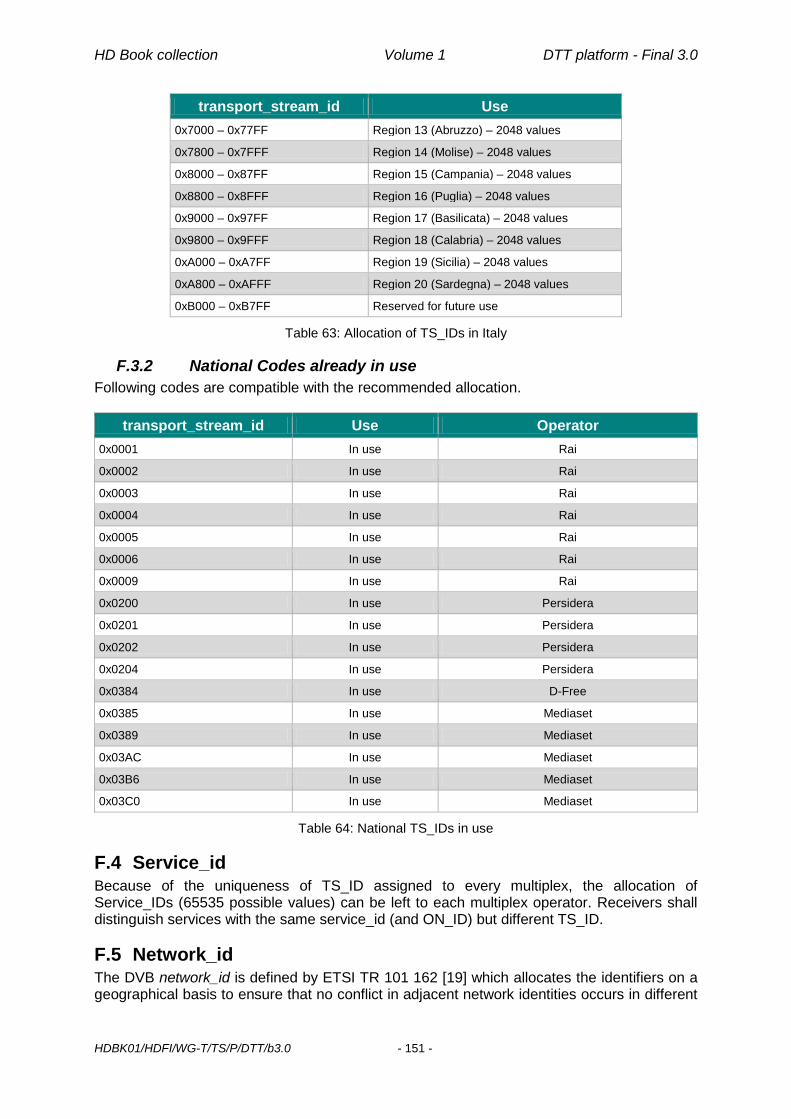
HD Book collection Volume 1 DTT platform - Final 3.0
HDBK01/HDFI/WG-T/TS/P/DTT/b3.0 - 151 -
transport_stream_id Use 0x7000 – 0x77FF Region 13 (Abruzzo) – 2048 values
0x7800 – 0x7FFF Region 14 (Molise) – 2048 values
0x8000 – 0x87FF Region 15 (Campania) – 2048 values
0x8800 – 0x8FFF Region 16 (Puglia) – 2048 values
0x9000 – 0x97FF Region 17 (Basilicata) – 2048 values
0x9800 – 0x9FFF Region 18 (Calabria) – 2048 values
0xA000 – 0xA7FF Region 19 (Sicilia) – 2048 values
0xA800 – 0xAFFF Region 20 (Sardegna) – 2048 values
0xB000 – 0xB7FF Reserved for future use
Table 63: Allocation of TS_IDs in Italy
F.3.2 National Codes already in use Following codes are compatible with the recommended allocation.
transport_stream_id Use Operator 0x0001 In use Rai
0x0002 In use Rai
0x0003 In use Rai
0x0004 In use Rai
0x0005 In use Rai
0x0006 In use Rai
0x0009 In use Rai
0x0200 In use Persidera
0x0201 In use Persidera 0x0202 In use Persidera 0x0204 In use Persidera 0x0384 In use D-Free
0x0385 In use Mediaset
0x0389 In use Mediaset
0x03AC In use Mediaset
0x03B6 In use Mediaset
0x03C0 In use Mediaset
Table 64: National TS_IDs in use
F.4 Service_id Because of the uniqueness of TS_ID assigned to every multiplex, the allocation of Service_IDs (65535 possible values) can be left to each multiplex operator. Receivers shall distinguish services with the same service_id (and ON_ID) but different TS_ID.
F.5 Network_id The DVB network_id is defined by ETSI TR 101 162 [19] which allocates the identifiers on a geographical basis to ensure that no conflict in adjacent network identities occurs in different

HD Book collection Volume 1 DTT platform - Final 3.0
HDBK01/HDFI/WG-T/TS/P/DTT/b3.0 - 152 -
geographic regions. The allocation is typically referred to as the DVB color map as shown in the following figure.
Figure 12: Colour map for allocating network_ids in terrestrial networks
The allocation of the network_id for countries in the European region comprising Italy is shown in the following table:
Country network_id Austrian Digital Terrestrial Television 0x3301 ÷ 0x3400 French Digital Terrestrial Television 0x3301 ÷ 0x340018 Italian Digital Terrestrial Television 0x3001 ÷ 0x3100 Slovenia Digital Terrestrial Television 0x3201 ÷ 0x3300 Spanish Digital Terrestrial Television 0x3101 ÷ 0x3200 Swiss Digital Terrestrial Television 0x3201 ÷ 0x3300
Table 65: Network_ids of interest
Network_ids shall not be used to uniquely identify a service. Network_ids shall instead be used to identify the country which a network belongs to for the purpose of LCN conflicts (see §7.3). In particular, if Italy has been selected as “Country” at first installation time, all networks whose network_id fits in the 0x3001÷0x3100 range shall be considered as belonging to Italy.
F.6 Network Name No assumption is or shall be made for this parameter.
18 France will likely go on using as single network_id for the whole country the same value assigned by DVB to French DTT as original_network_id (0x20FA)

HD Book collection Volume 1 DTT platform - Final 3.0
HDBK01/HDFI/WG-T/TS/P/DTT/b3.0 - 153 -
G Void

Page intentionally left blank

HD Book collection Volume 1 DTT platform - Final 3.0
HDBK01/HDFI/WG-T/TS/P/DTT/b3.0 - 155 -
H MHP CA API Implementation Guidelines for non CA smart cards
H.1 Purpose Scope of this Annex is to provide implementation guidelines for MHP CA API to be used with a Non-Ca Smart Card. The reference CA API is version 1.2. The complete JavaDoc is delivered within a separated file available on request to any interested party. Only classes and methods here defined must be implemented; it’s up to the programmer not to use the others. In the case other classes are instantiated or other methods are called, they should not work, which means null should be returned if necessary or no effects should be caused for methods without a return value. The aim of this specific implementation is to provide a way for MHP applications to know the general status of a smart card reader compliant with ISO 7816 specifications. This implementation will not interfere with Conditional Access smart cards, which means no critical classes or methods will be required. In the next sections, used classes, interfaces and methods are defined. In last section, an example is given.
All the exceptions that could be thrown using the required methods should obviously be implemented. Any other class, method, static value or interface not defined in this document should not be implemented.
H.2 Package it.dtt.ca
H.2.1 CaManager In this implementation this class will be used only to monitor smart card reader status.
H.2.1.1 Constructor Requested for implementation.
H.2.1.2 getCAProvider Should return the string “SATSA”, in capital letters as typed here.
H.2.1.3 getClient Returns the resource client associated to this object.
H.2.1.4 getSlots This will return an array of Slot objects, each one associated to one physical smart card reader. If only one reader is present, as often happens currently, it must be associated to first position in the array.
H.2.2 CaManagerFactory This class is the entry point to interact with the smart card reader. Only one actor at the same time can have a session opened.

HD Book collection Volume 1 DTT platform - Final 3.0
HDBK01/HDFI/WG-T/TS/P/DTT/b3.0 - 156 -
H.2.2.1 closeSession Only once the session is closed, another one can be opened. If this method is called when no session is opened, the exception NoSessionOpenedException will be called. If the ResourceClient passed in as a parameter is not the same that was passed opening the session, the exception OwnerUnknownException will be called.
H.2.2.2 getInstance This method will enable the process of interacting with the smart card status. In any case communication cannot work before openSession is called. To initialize the MHP CA API to work with a generic ISO 7816 smart card reader, these two parameters as inputs to the method should be used: provider = “SATSA” broadcaster = “ANY” This method will return an instance of CAManagerFactory that will allow opening a session. If the API is not implemented to support a Non-Ca Smart Card, it should throw the exception NoSuchProviderException. The exception AccessDeniedException will never be thrown in case of Non-Ca Smart Cards.
H.2.2.3 openSession Once the CAManagerFactory has been instantiated, this method call will enable a session. Only one actor at a time can call this method. Once the session is opened and till it’s not closed, any other call to this method will end up with the API throwing SessionAlreadyOpenedException.
H.2.3 CaObject Requested class.
H.2.3.1 Constructors Requested for implementation.
H.2.3.2 Methods Requested for implementation.
H.2.4 CaSession Requested class.
H.2.4.1 Constructors Requested for implementation.
H.2.4.2 Methods Requested for implementation.
H.2.5 Slot This class represent the physical smart card reader on the Set-Top box.
H.2.5.1 Constructors Requested for implementation. If only one reader is present, id 0 should be used.

HD Book collection Volume 1 DTT platform - Final 3.0
HDBK01/HDFI/WG-T/TS/P/DTT/b3.0 - 157 -
H.2.5.2 addSlotListener Requested.
H.2.5.3 getSlotID If only one reader is present, this method call will return 0.
H.2.5.4 getSmartCard This method is not required.
H.2.5.5 getStatus This method will get current status of the smart card reader. The possible return values are the ones defined for SlotEvent.
H.2.5.6 removeSlotListener Requested.
H.3 Package it.dtt.ca.event
H.3.1 CaEvent The implementation of this object is required to support the use of its derived class SlotEvent only. Other types of events are not requested.
H.3.2 SlotEvent Any time a change is notified in the smart card reader status, one SlotEvent is thrown. In the table below, all the possible events are shown with the specific parameters with whom the events should be generated (type, data, description) and the return value for toString() method call.
The CARD_ACCESS_DENIED is not used because once a valid smart card is inserted into the reader, the API has not any other way to communicate with a specific smart card provider software (I.e. with a CA Kernel from any Conditional Access provider)
Type Data Description toString() CARD_ERROR: this is thrown when the reader is able to communicate with the smart card but the smart card does not reply to a reset command 352 Null “Card Error” “SlotEvent.CARD_ERROR” CARD_IN: the smart card is inserted into the reader 350 Null “Smart Card inserted” “SlotEvent.CARD_IN” CARD_MUTED: the reader finds a smart card is inserted but there is no electrical communication 353 Null “Offers on-air update” “SlotEvent.CARD_MUTED” CARD_OUT: the smart card is removed from the reader 351 Null “Smart Card removed” “SlotEvent.CARD_OUT” CARD_VERIFYING: the reader is verifying the status
355 Null “Smart Card reader verifying” “SlotEvent.CARD_VERITYING”
ERROR_UNKNOWN: thrown when there is any other error trying to communicate with the smart card reader

HD Book collection Volume 1 DTT platform - Final 3.0
HDBK01/HDFI/WG-T/TS/P/DTT/b3.0 - 158 -
356 Null “Generic Smart Card reader error” “SlotEvent.CARD_UNKNOWN”
H.3.3 SlotListener This interface must be implemented by any application wanting to monitor the status of the smart card reader.
H.3.4 SlotEventReceived Requested.
H.4 Example This simple example shows how this implementation of the CA API, could be used.
public class Example implements SlotListener, ResourceClient;
. . . CAManagerFactory factory; CAManager manager; Slot reader; Slot[] slots;
. . .
/* Initialization of the API */ try {
factory = CAManagerFactory.getInstance(“SATSA”,”ANY”);
} catch (NoSuchProviderException) { System.out.println(“This API does not support ISO 7816 generic smart card reader monitoring”);
} /* Creation of the manager */ try {
manager = factory.openSession(this);
} catch (SessionAlreadyOpenedException) { System.out.println(“There is already an application using the CA API”);
} try { /* Getting smart card reader (single reader on the STB) */ slots = manager.getSlots(); reader = slots[0]; /* Checking current status */ if (slot.getStatus != SlotEvent.CARD_IN)
System.out.println(“There is a problem with the

HD Book collection Volume 1 DTT platform - Final 3.0
HDBK01/HDFI/WG-T/TS/P/DTT/b3.0 - 159 -
card”); /* Attaching the listener */ reader.addSlotListener(this); catch (SessionClosedException) { System.out.println(“The session has been closed”); } . . . public void slotEventReceived(SlotEvent event) {
System.out.println(“Error number “+event.getType()+”–“ +event.getDescription());
if (event.getType == SlotEvent.CARD_OUT) System.out.println(“Card was removed”);
. . . }

Page intentionally left blank

HD Book collection Volume 1 DTT platform - Final 3.0
HDBK01/HDFI/WG-T/TS/P/DTT/b3.0 - 161 -
I The new SATSA target
I.1 Introduction SATSA's Generic Connection Framework calls for opening a Connection to a Java application, identified by an ID (the AID). The vast majority of the cards issued in Italy, are standard based but unfortunately are not Java cards. Although an Application ID(s) could be, in theory, also set on these cards, this is not mandatory and most cards have issued without. It has been proved under test that any Connector.open("apdu...;target=a0.00...") issued against such cards returns a ConnectionNotFoundException. This is because the card has neither an AID set nor is a Java card with such application "listening". It has also been noticed that a Connector.open("apdu...;target=SAT") may also return NotImplemented as this is normally used on (U)SIM as defined per SIM Application Toolkit mode and the SATSA layer implementer may have made no provision for it. The above behaviors result in not being able to extract the data from the card. This is a technical downgrade as far as the OCF previous implementation is concerned, especially for a long awaited and final solution for the DTT smart card realm as the SATSA choice promised to be.
I.2 Proposed solution The proposed solution is based upon the following thoughts: • The first step consists in defining a new target, namely CXS, for the Connector.open as in Connector.open("apdu:0,target="CXS") as an example • Only when target=CXS is selected (and only in this case), if the SATSA layer enters into a "no card application" branch, instead of raising a ConnectionNotFoundException, the implemented SATSA layer will return the APDUConnection object successfully (i.e. no exception is raised). • Once the APDUConnection object is returned, the requesting MHP application may initiate and continue to exchange APDUs as usual (exchangeAPDU()) and eventually close the connection.
I.3 Solution advantages The proposed solution has the following advantages: • It would not impact any target=SAT implementation, if already in place in the implemented SATSA layer. On the other end it would not call for target=SAT implementation if is not in already in place (this is/could be nice on the SATSA layer implementer side). • It will relief the MHP applications from coding envelope APDUs and the SATSA layer from unpacking envelopes when this is not explicitly needed (this is the case for Italian CNS, CRS and CIE) • It will also work for chip cards which being ISO 7816 compliant have, nevertheless, evolved differently from the e-government cards (namely CNS,CRS or CIE) standards • This approach is also compatible with smart cards which are not Java cards but have or manage Application IDs. In this case both target=CXS and target=a0.00.... (whatever) strings could be used interchangeably
I.4 An example Applications running in a SATSA implementation that supports opening a connection with target = CXS, can communicate with the smart card OS by using APDUConnection. There are various constraints on this type of usage, which are definitively detailed by the DVB and DGTVi relevant documents related to Security and Trust Services API

HD Book collection Volume 1 DTT platform - Final 3.0
HDBK01/HDFI/WG-T/TS/P/DTT/b3.0 - 162 -
Specification. Further limitations may apply within the smart card issuer (i.e. the issuing institution or enterprise) or the smart card manufacturer. Opening a connection using CXS is straightforward. The following example attempts a CXS connection on slot 0. APDUConnection cxs; cxs = (APDUConnection)Connector.open("apdu:0;target=CXS"); Once the connection is established, the application can send APDU commands to the smart card using the exchangeAPDU() method. Use the exchangeAPDU() method to send a command to a card application and receive a response. Pass a byte array containing a command APDU to exchangeAPDU(). The command is sent to the card. When the card sends its response APDU, this method returns the response as another byte array. A variety of exceptions might be thrown if communications failures or other disasters occur. byte[] apdu = { (byte)0x00, (byte)0x20, (byte)0x00, (byte)0x82, (byte)0x04, (byte)0x01, (byte)0x02, (byte)0x03, (byte)0x04, (byte)0x00 }; byte[] response = cxs.exchangeAPDU(apdu); The exchangeAPDU() method blocks until a response is received from the card application. To close an APDUConnection, simply call its close() method as shown in the following example. cxs.close(); If you close a connection that is being used by other threads to exchange APDUs, the connection is closed immediately and the exchangeAPDU() methods in other threads throw InterruptedException.

HD Book collection Volume 1 DTT platform - Final 3.0
HDBK01/HDFI/WG-T/TS/P/DTT/b3.0 - 163 -
J EIT schedule compression J.1 Introduction In order to allow efficient transmission of schedule data spanning more than just a couple of days, a private compressed version of EIT schedule tables has been introduced in §7.2.6.4.
J.2 Compression algorithm For compressing EIT schedule tables the ZLIB algorithm, as specified in RFC 1950 [49], is applied to the event loop in event_information_sections. Section_length and CRC_32 are updated accordingly. The receiver SHALL support the Deflate compression algorithm as specified in RFC 1951 [50]. The receiver is not required to support other compression algorithms.

Page intentionally left blank

HD Book collection Volume 1 DTT platform - Final 3.0
HDBK01/HDFI/WG-T/TS/P/DTT/b3.0 - 165 -
K Streaming monitoring API Refer to GEM [62] Annex N.2. For representing audio and video coding formats the MPEG-7 termIDs classification schemes defined and maintained by EBU respectively in http://www.ebu.ch/metadata/cs/ebu_AudioCompressionCodeCS.xml and http://www.ebu.ch/metadata/cs/ebu_VideoCompressionCodeCS.xml SHALL be used. The array returned by VideoStreamQualityInfo must be ordered in increasing bit rate order ([0] lower bit rate).

Page intentionally left blank
HD Book collection Volume 1 DTT platform - Final 3.0
HDBK01/HDFI/WG-T/TS/P/DTT/b3.0 - 167 -
L OTT content referencing API Refer to GEM [62] Annex AU.2.

Page intentionally left blank

HD Book collection Volume 1 DTT platform - Final 3.0
HDBK01/HDFI/WG-T/TS/P/DTT/b3.0 - 169 -
M 2D service compatibility within 3DTV M.1 Introduction Starting from the work done in DVB (Annex B to [57]), this Annex provides implementation guidelines on possible modes of operation of frame compatible plano-stereoscopic 3DTV services that provide service compatible operation with 2D (HDTV) services under certain conditions. This kind of service backward compatibility is enabled by the HDTV decoder capability of extracting one of the frame-packed views of the frame compatible plano-stereoscopic 3DTV service video stream, and up-scaling it to simulate the reception of an HDTV service. Two H.264/AVC video layer signalling fields are used for this purpose [58]: Cropping Rectangle which describes the active part of a decoded picture; Sample Aspect Ratio (SAR) within the Video Usability Information (VUI) which
provides the needed scaling to generate the output image. Such service compatible modes give service providers the chance to transmit a single service that provides both frame compatible plano-stereoscopic 3DTV video and reduced-resolution (halved) HDTV video concurrently, whereas normally HDTV coverage with the same source content would be provided with a separate dedicated HDTV service.
M.2 3DTV use cases The following Figure 15 depicts the predominant use cases for the reception of frame compatible plano-stereoscopic 3DTV services, and the co-existence of frame compatible plano-stereoscopic 3DTV compliant receivers with existing HDTV (i.e. non-3DTV) equipment, taking into account the various capabilities with respect to 3DTV and the different kind of receivers (e.g. STB or iDTV).
Figure 13: Frame compatible plano-stereoscopic 3DTV IRD use cases
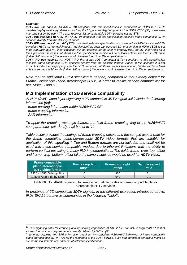
HD Book collection Volume 1 DTT platform - Final 3.0
HDBK01/HDFI/WG-T/TS/P/DTT/b3.0 - 170 -
Legenda: 3DTV IRD use case A: An IRD (STB) compliant with this specification is connected via HDMI to a 3DTV capable display device (qualified as such by the 3D_present flag being set to 1 in HDMI VSDB [53] or because manually set by the user). The user receives frame compatible 3DTV services via the STB. 3DTV IRD use case B: A 3DTV IRD (iDTV) compliant with this specification receives frame compatible 3DTV services directly from the delivery channel. 3DTV IRD use case C: An IRD (STB) compliant with this specification is connected via HDMI to a non-3DTV compliant HDTV set (or which doesn’t qualify itself as such e.g. because 3D_present flag in HDMI VSDB is set to 0). Naturally, due to TV set limitation, it is not possible for the user to properly view the 3DTV services as in the 2 previous use cases but, thanks to this specification, he/she will be at least able to see them in 2D mode (halved HD resolution) if operators would transmit them in a 2D-compatible form. 3DTV IRD use case D: An HDTV IRD (i.e. a non-3DTV compliant iDTV) compliant to this specification receives frame compatible 3DTV services directly from the delivery channel. Again, in this scenario it is not possible for the user to properly view the 3DTV services, but, thanks to this specification, he/she will be at least able to see them in 2D mode (halved HD resolution) if operators would transmit them in a 2D-compatible form. Note that no additional PSI/SI signalling is needed, compared to that already defined for Frame Compatible Plano-stereoscopic 3DTV, in order to realize service compatibility for use cases C and D.
M.3 Implementation of 2D service compatibility At H.264/AVC video layer signalling a 2D-compatible 3DTV signal will include the following information [58]: - frame packing information within H.264/AVC SEI - frame cropping information - SAR information To apply the cropping rectangle feature, the field frame_cropping_flag of the H.264/AVC seq_parameter_set_data() shall be set to ‘1’. Table below provides the settings of frame cropping offsets and the sample aspect ratio for the frame compatible plano-stereoscopic 3DTV video formats that are suitable for application of this signalling19. Top-and-Bottom formats are not included and shall not be used with these service compatible modes, due to inherent limitations with the ability to perform vertical upscaling in many IRD implementations. The fields frame_crop_top_offset and frame_crop_bottom_offset take the same values as would be used for HDTV video.
Frame compatible plano-stereoscopic 3DTV video format
Frame crop left offset
Frame crop right offset
Sample aspect ratio
1920 x 1080i Side-by-Side 0 960 2:1 1280 x 720p Side-by-Side 0 640 2:1
Table 66: H.264/AVC signalling for service compatible modes of frame compatible plano-stereoscopic 3DTV services
In presence of 2D-compatible 3DTV signals, in the different use cases introduced above, IRDs SHALL behave as summarized in the following Table20:
19 This signaling calls for cropping and up scaling capabilities of HDTV (i.e. non-3DTV cognizant) IRDs that exceed the minimum requirements currently defined by DVB in [9]. 20 Ignoring cropping and SAR information requires non-compliant H.264/AVC behaviour of frame compatible plano-stereoscopic 3DTV IRDs for the rendering of the 3DTV service. Such non-compliant behaviour might be overcome via suitable amendments of relevant specifications.

HD Book collection Volume 1 DTT platform - Final 3.0
HDBK01/HDFI/WG-T/TS/P/DTT/b3.0 - 171 -
Use cases STB (if present) behaviour TV behaviour
A frame packing information is recognized within SEI and signalled over HDMI
frame cropping offsets and sample aspect ratio combinations used for service compatible modes are ignored
frame packing information is recognized over HDMI and duly applied
B frame cropping offsets and sample aspect ratio combinations used for service compatible modes are ignored
frame packing information is recognized within SEI and duly applied
C21 frame packing information within SEI is ignored
frame cropping offsets and sample aspect ratio combinations used for service compatible modes are normally interpreted
full frame 2D signal received over HDMI is displayed
D
frame packing information within SEI is ignored
frame cropping offsets and sample aspect ratio combinations used for service compatible modes are normally interpreted
full frame 2D signal is displayed
Table 67: Expected IRD behaviour for 2D service compatible 3DTV transmissions
Above behavior is expected for both broadcast and broadband delivery of H.264/AVC 3DTV service components as well as for both the containers (TS and MP4) used for broadband delivery of H.264/AVC 3DTV service components.
21 An IRD (STB) compliant with this specification when connected via SCART to any TV set is expected to behave as in this use case, presenting on SCART the downscaled version of full frame 2D decoded signal

Page intentionally left blank

HD Book collection Volume 1 DTT platform - Final 3.0
HDBK01/HDFI/WG-T/TS/P/DTT/b3.0 - 173 -
N PRF Example (Informative) N.1 Introduction The following example describes a Permission Request File (PRF) which includes requests for basic, system and private resources.
N.2 Example <?xml version="1.0"?> <permissionrequestfile orgid="0x000023d2" appid="0xa020"> <!--Basic Resources requests --> <file value="true"></file> <applifecyclecontrol value="true"></applifecyclecontrol> <returnchannel> <defaultisp></defaultisp> <phonenumber>+3583111111</phonenumber> <phonenumber>+3583111112</phonenumber> <phonenumber></phonenumber> </returnchannel> <tuning value="false"></tuning> <servicesel value="true"></servicesel> <userpreferences read="true" write="false"></userpreferences> <!--System Resource requests --> <systemresourcecredential id=”0x01” value=”true”> <grantorname name="ServicePlatformProviderAcme"></grantorname> <expirationdate date="24/12/2032"></expirationdate> <certchainfileid>3</certchainfileid> </systemresourcecredential> <!--System Resource requests --> <systemresourcecredential id=”0x04” value=”true”> <grantorname name="ServicePlatformProviderAcme"></grantorname> <expirationdate date="24/12/2032"></expirationdate> <certchainfileid>3</certchainfileid> </systemresourcecredential> <!--Private Resource requests --> <privateresourcecredential id=”0xAA” value=”true”> <grantorname name="ServiceProviderA"></grantorname> <expirationdate date="24/12/2032"></expirationdate> <certchainfileid>4</certchainfileid> </privateresourcecredential> </permissionrequestfile>

Page intentionally left blank

HD Book collection Volume 1 DTT platform - Final 3.0
HDBK01/HDFI/WG-T/TS/P/DTT/b3.0 - 175 -
O DRM Agent as a system resource (Informative) O.1 Introduction The following example describes a possible usage of the BAS mechanisms in a real scenario. In this example a specific DRM Agent is defined as a system resource with id= “0x01” that can only be accessed by legitimate applications, i.e. those coming from a properly entitled service platform provider (ServicePlatformProviderAcme).
O.2 System resource declaration The system resource representing access to this DRM Agent can be defined as follows in a proper PRF: <systemresourcecredential id=”0x01” value=”true”> <grantorname name="ServicePlatformProviderAcme"></grantorname> <expirationdate date="24/12/2032"></expirationdate> <certchainfileid>3</certchainfileid> </systemresourcecredential>
An example of the relevant data in the certificate pointed by the certchainfileid element can be the following: Certificate: Data: Version: 1 (0x0) Serial Number: 7829 (0x1e95) Signature Algorithm: md5WithRSAEncryption Issuer: C=IT, O= ServicePlatformProviderAcme, OU=Certification Services Division, CN= ServicePlatformProviderAcme Server CA/[email protected] Validity Not Before: Jul 9 16:04:02 2011 GMT Not After : Jul 9 16:04:02 2013 GMT Subject: C=IT, O=ServiceProviderA, OU=foo, CN=www.serviceprovidera.org/emailAddress=foo@ serviceprovidera.org Subject Public Key Info: … A root certificate (trust anchor) needs to be installed in the receiver in order to authenticate the certificate and match the grantorname required by the systemresourcecredential.
O.3 Verification phase A receiver downloads the BAS-signalled application from an application server by establishing a HTTPS secure connection. During the setup of the connection, the server and the client exchange their respective certificates and both are mutually authenticated as part of a common trusted environment (e.g., by relying on certificates issued by the entitled Trust Authority). Once the download of the application is completed, the BAS-compliant receiver looks for a valid PRF file in the file structure of the application. If the PRF file exists, then the basic resources listed in the PRF file are parsed as well as the resources defined as system and private (systemresourcecredential and privateresourcecredential elements), like the specific DRM Agent defined in this case. Using the certchainfileid the related certificate is retrieved by a BAS-compliant receiver supporting the specific DRM Agent. The certificate is authenticated and the procedure to match the grantorname with the Issuer organizationName of the root certificate and the Subject organizationName of the certificate associated to the requested system resource with the Subject organizationName in the certificate provided during TLS handshake by the

HD Book collection Volume 1 DTT platform - Final 3.0
HDBK01/HDFI/WG-T/TS/P/DTT/b3.0 - 176 -
server from which the application has been downloaded is performed. If this procedure is completed successfully and the organizationName is recognised as a legitimate owner of the resource, then the application, once executed, can access the DRM Agent. Otherwise any operation which involves this DRM Agent will raise a SecurityException.

HD Book collection Volume 1 DTT platform - Final 3.0
HDBK01/HDFI/WG-T/TS/P/DTT/b3.0 - 177 -
P XML schema and example for BAS white list P.1 XML schema The schema to be adopted for the XML file exposing BAS white list is the following: <?xml version="1.0" encoding="utf-8"?> <xs:schema targetNamespace="urn:hdfi:bas:schema:whitelistresources:2012" attributeFormDefault="unqualified" elementFormDefault="qualified" xmlns:xs="http://www.w3.org/2001/XMLSchema" xmlns="urn:hdfi:bas:schema:whitelistresources:2012"> <xs:annotation> <xs:appinfo>BAS Whitelist for Access to Receiver Resources</xs:appinfo> <xs:documentation xml:lang="en"> This Schema defines the whitelist of owners of system and private resources
for a receiver. </xs:documentation> </xs:annotation> <!-- Whitelist: main element --> <xs:element name="Whitelist" type="Whitelisttype"/> <xs:complexType name="Whitelisttype"> <xs:sequence> <xs:element name="Systemresources" type="Systemresourcestype"
minOccurs="1"/> <xs:element name="Privateresources" type="Privateresourcestype"
minOccurs="1"/> <xs:any namespace="##other" processContents="lax" minOccurs="0"
maxOccurs="unbounded"/> </xs:sequence> </xs:complexType> <xs:complexType name="Systemresourcestype"> <xs:sequence> <xs:element name="Owner" type="Ownertype" minOccurs="0"
maxOccurs="unbounded"/> <xs:any namespace="##other" processContents="lax" minOccurs="0"
maxOccurs="unbounded"/> </xs:sequence> </xs:complexType> <xs:complexType name="Privateresourcestype"> <xs:sequence> <xs:element name="Owner" type="Ownertype" minOccurs="0"
maxOccurs="unbounded"/> <xs:any namespace="##other" processContents="lax" minOccurs="0"
maxOccurs="unbounded"/> </xs:sequence> </xs:complexType> <xs:complexType name="Ownertype"> <xs:sequence> <xs:element name="Resource" type="Resourcetype" minOccurs="1"
maxOccurs="unbounded"/> <xs:any namespace="##other" processContents="lax" minOccurs="0"
maxOccurs="unbounded"/> </xs:sequence> <xs:attribute name="organization" type="xs:string" use="required"/> <xs:attribute name="issuer" type="xs:string" use="required"/> <xs:anyAttribute namespace="##other" processContents="lax"/> </xs:complexType>

HD Book collection Volume 1 DTT platform - Final 3.0
HDBK01/HDFI/WG-T/TS/P/DTT/b3.0 - 178 -
<xs:complexType name="Resourcetype"> <xs:attribute name="id" type="xs:string" use="required"/> <xs:anyAttribute namespace="##other" processContents="lax"/> </xs:complexType> </xs:schema>
P.2 Example The following white list represents a receiver supporting:
• 2 system resources within the PlatformProviderA echosystem. • 1 system resource within the PlatformProviderB echosystem. • 2 private resources owned by ServiceProviderX. Requests will be validated using the
PlatformProviderA anchor • 1 private resource owned by ServiceProviderY. Requests will be validated using the
TrustProviderA anchor It should be noted that resource ids must be unique only within a namespace so 2 resources with different ids under different namespaces may actually coincide. <?xml version="1.0" encoding="utf-8"?> <Whitelist xmlns="urn:hdfi:bas:schema:whitelistresources:2012" xmlns:xsi="http://www.w3.org/2001/XMLSchema-instance" xsi:schemaLocation="urn:hdfi:bas:schema:whitelistresources:2012"> <Systemresources> <Owner organization="PlatformProviderA" issuer="PlatformProviderA"> <Resource id="0x01"/> <Resource id="0x02"/> </Owner> <Owner organization="PlatformProviderB" issuer="PlatformProviderB"> <Resource id="0x01"/> </Owner> </Systemresources> <Privateresources> <Owner organization="ServiceProviderX" issuer="PlatformProviderA"> <Resource id="0x03"/> <Resource id="0x04"/> </Owner> <Owner organization="ServiceProviderY" issuer="TrustProviderA"> <Resource id="0x05"/> </Owner> </Privateresources> </Whitelist> After receiving
• an RCMM signed by PlatformProviderA which has added PlatformProviderC trust anchor and
• an RCMM signed by PlatformProviderA which has removed PlatformProviderB trust anchor
the above white list will change as follows: <?xml version="1.0" encoding="utf-8"?> <Whitelist xmlns="urn:hdfi:bas:schema:whitelistresources:2012" xmlns:xsi="http://www.w3.org/2001/XMLSchema-instance" xsi:schemaLocation="urn:hdfi:bas:schema:whitelistresources:2012"> <Systemresources> <Owner organization="PlatformProviderA" issuer="PlatformProviderA"> <Resource id="0x01"/> <Resource id="0x02"/> </Owner> <Owner organization="PlatformProviderC" issuer="PlatformProviderC"> <Resource id="0x01"/> <Resource id="0x02"/>

HD Book collection Volume 1 DTT platform - Final 3.0
HDBK01/HDFI/WG-T/TS/P/DTT/b3.0 - 179 -
</Systemresources> <Privateresources> <Owner organization="ServiceProviderX" issuer="PlatofrmProviderA"> <Resource id="0x03"/> <Resource id="0x04"/> </Owner> <Owner organization="ServiceProviderY" issuer="TrustProviderA"> <Resource id="0x05"/> </Owner> </Privateresources> </Whitelist>

Page intentionally left blank

HD Book collection Volume 1 DTT platform - Final 3.0
HDBK01/HDFI/WG-T/TS/P/DTT/b3.0 - 181 -
Q Special PAE provisions for DASH Live (Dynamic MPD) case
Q.1 Definitions In case of DASH live streaming using dynamic MPD [60], the following definitions apply:
T0: Presentation time of the first segment made available on the server for this live content
Tn: Presentation time of the segment associated with the client wall-clock time NOW Tx: Presentation time of the segment currently presented by the client. If no seek
methods were previously invoked on the client, Tx is equal to Tn T0bd: Tn - timeShiftBufferDepth, i.e. presentation time of the first segment available
on the server taking into account timeShiftBufferDepth parameter (if present in the MPD)
T00: T0 if timeShiftBufferDepth is not present in the MPD or if it is present but (Tn - T0) < timeShiftBufferDepth, T0bd otherwise
Ry: Time parameter passed to the player to force a seek. It is a time value relative to T00
Tp: Presentation time of the segment being presented by the client when it executes a pause command
Tr: Presentation time of the first segment presented by the client when it executes a resume command
As defined in DASH [60], Presentation time is the time associated to an access unit that maps it to the Media Presentation timeline. DASH standard itself warns that a client not synchronized with a DASH server, which in turn is expected to be synchronized to UTC, may experience issues in accessing Segments as the Segment availability times provided by the server and the local time NOW may not be synchronized. Therefore, DASH clients are expected to synchronize their clocks to a globally accurate time standard.
Q.2 Content duration When javax.media.Player.getDuration() or javax.media.CachingControl.getContentLength() method is invoked for a DASH content with a Dynamic MPD, it will return the duration (Tn - T00) of the live content from the first segment available (taking into account the timeShiftBufferDepth value if present in the MPD) to the segment associated with the client wall-clock time.
Q.3 Getting media presentation time When javax.media.Player.getMediaTime() method is invoked for a DASH content with a Dynamic MPD, it will return Tx - T00.
Q.4 Setting media presentation time When javax.media.Player.setMediaTime()method is invoked for a DASH content with a Dynamic MPD, the following provisions apply:
• setMediaTime(Ry) with Ry=0 will force the client to present the first segment available for this presentation, i.e. the segment with presentation time T00
• setMediaTime(Ry) to any time Ry within the valid content duration (Tn -T00, 0) will force the client to present the segment associated with the selected presentation time

HD Book collection Volume 1 DTT platform - Final 3.0
HDBK01/HDFI/WG-T/TS/P/DTT/b3.0 - 182 -
• setMediaTime(Ty) to any time Ry “in the future”, i.e. outside the valid content duration (Tn -T00 ,0) will force the client to present the segment associated with the client wall-clock time NOW, i.e. as setMediaTime(Tn-T00) had been invoked
Q.5 Pausing and resuming a media presentation When presentation of a DASH content with a Dynamic MPD is paused (at time Tp) and then resumed, it will start at time Tr=max(Tp, T00).


Printed in November 2014 by Meti S.a.s. (CS) - Italy
on behalf of Associazione HD Forum Italia Viale del Policlinico, 147
00161 Roma www.hdforumitalia.org