Comparison of Remote Monitoring Systems - A Review
13
International Journal of Engineering Research and General Science Volume 3, Issue 6, November-December, 2015 ISSN 2091-2730 82 www.ijergs.org Comparison of Remote Monitoring Systems - A Review Swathi.K 1 , Kishore Balasubramanian 2 and Muthuvel V 3 1 PG scholar, Applied Electronics, Dr.Mahalingam College of Engineering and Technology, Pollachi [email protected] 2 Assistant Professor, Department of EEE, Dr.Mahalingam College of Engineering and Technology, Pollachi [email protected] 3 Assistant Professor, Department of EEE, Dr.Mahalingam College of Engineering and Technology, Pollachi [email protected] Abstract— This paper presents a detailed study on comparison of different remote monitoring systems. There are many systems for remote monitoring and control, designed as either commercial products or experimental research platforms. It is noticed that most of the research are carried out in categories such as Internet based Monitoring via Servers, GPRS modems, etc. There are different other approaches for GSM-SMS protocols using GSM module individually or in combination besides using Wireless technologies such as Sensor Networks, Bluetooth, Wi-Fi, Zigbee and RF. For choosing the appropriate monitoring system for an application, a number of characteristics are important. A review of different monitoring systems with their characteristics is presented. Keywords— Remote monitoring, internet-based monitoring, , Wireless technologies, Bluetooth, Zigbee, Wi-Fi, General Packet Radio Service (GPRS). INTRODUCTION Remote monitoring includes data from gauges and sensors like soil moisture, pressure, environmental, etc. It is used to know the status of farm gates and building doors (open/close), irrigation valves and pumping equipment. It helps to view the video of operation in live mode, monitoring of greenhouses, livestock enclosures and storage facilities. Conventional wired monitoring system provides reliable solution in data transmission but suffers from several limitations. Apart from the physical constraints during laying of the data cables, the use of these cables also increases installation and maintenance cost. Besides, for outdoor application such as PV systems, continuous exposure to sun beam and rains may reduce the lifespan of the system (Spertino & Corona, 2013). To overcome these issues, wireless monitoring system is favoured over its cable-based counterpart. In this project, a Zigbee-based wireless monitoring system is designed and built as a replacement to the conventional cable-based monitoring system for a grid-tied PV system. Various aspects of the system, from design to construction and testing, are detailed here. Besides that, a PC-based application integrated with web-based function is designed and implemented in order to allow remote control of the system as well as easy access of the data over the internet. CLASSIFICATION OF REMOTE MONITORING SYSTEMS In a monitoring system, it is important to choose a method through which the users can access the monitored data effectively. For the monitoring of a system, users should have easy and prompt access to the data, in order to provide timely evaluation on the system performance, as well as to provide counter measures should any failure is detected. Based on the previous works surveyed, it is found that web-based monitoring system can be an attractive monitoring method,as it enables data to be distributed among remote users and userscan view data from any device with internet connectivity.
-
Upload
phungduong -
Category
Documents
-
view
216 -
download
1
Transcript of Comparison of Remote Monitoring Systems - A Review

International Journal of Engineering Research and General Science Volume 3, Issue 6, November-December, 2015 ISSN 2091-2730
82 www.ijergs.org
Comparison of Remote Monitoring Systems - A Review
Swathi.K1 , Kishore Balasubramanian
2 and Muthuvel V
3
1PG scholar, Applied Electronics, Dr.Mahalingam College of Engineering and Technology, Pollachi
2Assistant Professor, Department of EEE, Dr.Mahalingam College of Engineering and Technology, Pollachi
3Assistant Professor, Department of EEE, Dr.Mahalingam College of Engineering and Technology, Pollachi
Abstract— This paper presents a detailed study on comparison of different remote monitoring systems. There are many systems for
remote monitoring and control, designed as either commercial products or experimental research platforms. It is noticed that most of
the research are carried out in categories such as Internet based Monitoring via Servers, GPRS modems, etc. There are different other
approaches for GSM-SMS protocols using GSM module individually or in combination besides using Wireless technologies such as
Sensor Networks, Bluetooth, Wi-Fi, Zigbee and RF. For choosing the appropriate monitoring system for an application, a number of
characteristics are important. A review of different monitoring systems with their characteristics is presented.
Keywords— Remote monitoring, internet-based monitoring, , Wireless technologies, Bluetooth, Zigbee, Wi-Fi, General Packet
Radio Service (GPRS).
INTRODUCTION
Remote monitoring includes data from gauges and sensors like soil moisture, pressure, environmental, etc. It is used to know
the status of farm gates and building doors (open/close), irrigation valves and pumping equipment. It helps to view the video of
operation in live mode, monitoring of greenhouses, livestock enclosures and storage facilities.
Conventional wired monitoring system provides reliable solution in data transmission but suffers from several limitations.
Apart from the physical constraints during laying of the data cables, the use of these cables also increases installation and maintenance
cost. Besides, for outdoor application such as PV systems, continuous exposure to sun beam and rains may reduce the lifespan of the
system (Spertino & Corona, 2013). To overcome these issues, wireless monitoring system is favoured over its cable-based
counterpart. In this project, a Zigbee-based wireless monitoring system is designed and built as a replacement to the conventional
cable-based monitoring system for a grid-tied PV system. Various aspects of the system, from design to construction and testing, are
detailed here. Besides that, a PC-based application integrated with web-based function is designed and implemented in order to allow
remote control of the system as well as easy access of the data over the internet.
CLASSIFICATION OF REMOTE MONITORING SYSTEMS
In a monitoring system, it is important to choose a method through which the users can access the monitored data effectively.
For the monitoring of a system, users should have easy and prompt access to the data, in order to provide timely evaluation on the
system performance, as well as to provide counter measures should any failure is detected. Based on the previous works surveyed, it is
found that web-based monitoring system can be an attractive monitoring method,as it enables data to be distributed among remote
users and userscan view data from any device with internet connectivity.

International Journal of Engineering Research and General Science Volume 3, Issue 6, November-December, 2015 ISSN 2091-2730
83 www.ijergs.org
INTERNET BASED MONITORING
Internet monitoring is one of the common approaches for remote monitoring. Many researchers have worked in field of
Internet based remote monitoring. They developed home gateway system for interconnecting home network consisting of IEEE 1394
AV network and X10 power line home automation network with Internet. This provided remote access functions from Internet for
digital AV appliances like Digital Video Camera, Digital VCR connected to IEEE 1394 network and home appliances like TV, desk
lamp, electric fan connected to X10 controller.
Java based home automation system via World Wide Web were developed. The home appliances were controlled from ports
of embedded system board connected to PC based server at home. X10 controller interfaced through serial port to PC server for
control of devices was invented. The Common Gateway Interface (CGI) is used to interface between the browser and the X10 protocol
via http connection. The server executes CGI programs in order to satisfy a particular request from the browser, which expresses its
request using the http.
Model of web services based email extension for remote monitoring of embedded systems which integrates web services
into emails. It uses a general purpose email messaging framework to connect devices and manipulators. This low cost model fits for
systems with low connection bandwidth, small data transportation volume and non-realtime control, e.g., monitoring of home
appliances and remote meter-reading.
A system for controlling home electrical appliances over the internet uses Bluetooth wireless technology to provide a link
from the appliance to the Internet and Wireless Application Protocol (WAP) to provide a data link between the Internet and a mobile
phone. However, technical details relating controller are not revealed.
Design and implementation of an Internet home automation system was made available. The design uses an embedded
controller based on C8051F005 microcontroller which is connected to a PC-based home Web server via RS232 serial port. The home
appliances are connected to the input/output ports and the sensors are connected to the analog/digital converter channels of the
embedded controller. The software of the system is based on the combination of Keil C, Java Server Pages, and JavaBeans, and
dynamic DNS service (DDNS) client. Password protection is used to block the unauthorized user from accessing to the server [5].
A remote wireless monitoring system for off grid Wind turbine based on the GPRS and the Internet was developed. The
remote monitoring system is made up of three parts: controlling terminal, central monitoring computer and communication network.
Controlling terminal consists of microcontroller ARM7 LM3S1138, data acquisition module and GPRS communication module
WAVECOM Q2406B connected to ARM7 system using serial port. GPRS module sends parameters relating wind turbine to central
monitoring computer. The client can access central monitoring computer server through Internet and know parameters of different
wind turbines[12].
Key Press Markup Language (KPML) and SIP Event Package was introduced to control devices in the home environment
remotely without the need for specialized hardware in the home devices. KPML provides an efficient, reliable protocol for the remote
control of consumer devices using plain old telephones with 12-digit keypads using Internet transport technologies. Figure 1 shows
Key Press Markup Language (KPML) with two sites.
The architecture of embedded remote monitoring system based on Internet has been developed by the researchers. The
system adopts embedded web server as a central monitoring node and results in improvement in stability and reliability of system.
Moreover, utilization of dynamic monitoring web based on Java Applet improves the response capability and brings convenience for
complex monitoring web design.
Wireless remote monitoring system based on the GPRS (General Packet Radio Service) and the MCU (Micro programmed
Control Unit) was designed. System is based on 89C58 microcontroller and PIML GPRS-MODEM as the core, can collect data from

International Journal of Engineering Research and General Science Volume 3, Issue 6, November-December, 2015 ISSN 2091-2730
84 www.ijergs.org
Figure 1: Key press markup language (KPML)
Eight sensors control two-way Data Acquisition, in the local real-time display and support remote Internet monitoring. The
data from sensors are encoded, sent to the WEB server (fixed IP address or fixed domain name website) through the GPRS channel.
The system also accepts commands from remote monitoring centre.
Table 1: Comparison of different remote monitoring systems
Sl.no
Techno
logy Processor
Monitoring
Station
Modules
Interfaced Tools
Programming
Code
1. Internet 8051 family PC None Keil IDE Java, Interactive
C
2. Internet PIC16 PC None MPLAB IDE UML, C
3. Bluetooth Atmega64 PC TDK Blu2i AVR Studio C
4. Bluetooth Atmega168 Mobile Bluegiga WT11 AVR Studio,
Symbian
Interactive C,
Pythan
5. Bluetooth Atmega32 Mobile CBOEMSPA312 AVR studio,
Eclipse 3.2.2 C, Java
6. RFID Parallex
P8X32A PC
RFID Reader,
ENC 28J60
Propeller
tool, Spin
compiler
Spin
7. RF Atmega 48 PC RDM-A4FZ AVR Studio C

International Journal of Engineering Research and General Science Volume 3, Issue 6, November-December, 2015 ISSN 2091-2730
85 www.ijergs.org
8. RF 8051 family PC nRF905, Si4421 Keil IDE C51
9. GSM 8051 family Mobile Sony Ericsson
GM47 Keil IDE Visual C++
10. GSM-
FPGA 8051 Mobile
MAXON MM-
6854
Xilinx ISE
6.2i VHDL
11. GSM MSP430F149 PC Siemens TC35 C430 IDE C
12. GSM ARM7 PC, Mobile Siemens TC35 Flashmagic C
13. GSM-
Internet
Atmega128,
PIC 18 PC, Mobile Siemens TC35
AVR Studio,
MPLAB IDE C
14. GSM 8051 family PC Nokia FBUS Keil IDE,
Linux C, Java
15.
GSM-
Internet-
speech
PIC16 Mobile Siemens TC35 MPLAB C
16. GSM-WSN 8051 family PC, Mobile Siemens TC35,
CC1100 Keil IDE C51
17. GSM-
Zigbee Atmega 128 Mobile
Sony Ericsson
T290i, EM357
IDE & C
compiler C
18. GSM-
Zigbee 8051 Mobile
GM862QUAD-
PY, CC2430
Keil IDE,
Symbian C, Pythan
19. GSM-
Zigbee 8051 PC/Mobile Siemens TC35 Keil IDE C/C++
20. GPRS ARM7 CC2430 nRF24E1 µC/OS-II
21. GPRS 8051 family PC SIM300,
SN65LBC184
Keil IDE
Visual C
22. RF Atmega128,
APXA271 PC CC2420
AVR Studio,
TinyOS C
23. RF APXA271 PC CC2420 TinyOS nesC
Table 1 explains the comparison of different remote monitoring systems with respect to its technology, processor used, Monitoring
station, Modules Interfaced, tools and programming code.
Wireless remote image monitoring system based on GSM/GPRS and ARM_Linux developing environment was developed.
The monitoring system uses S3C2410 RISC MCU -ARM920Core, USB Web camera, SD Card and UART GPRS module. ARM
Linux operating system is loaded on SD Card. APIs of Video4Linux kernel are used to realize image acquisition of the system,
through PPP dial-up to access the GPRS, through network programming to realize the transmission of the image.
Application on remote monitoring system of reservoir based on GPRS was developed. GPRS data terminal hardware
includes the intelligent processing module, remote communication module, serial interface module and display module. Intelligent
processing module contains two chips AT89C55 microcontroller and serial E2PROM X25045. AT89C55 is used to transmit data
between remote communication module, A/D conversion module and display module. To ensure that data will not be lost because of
power outages, serial E2PROM X25045 devices is adopted for data storage. Remote communication module includes GPRS wireless
module, SIM card and serial module MAX3238. Database mainly stores various parameters of the flood accommodation procedures
for the user and reservoir historical hydrological data, such as electric power generated, relation curve of water level flows, the water
storage capacity curve, and discharge curve, unit's efficiency curve of different conditions, historical flood data and flood information.

International Journal of Engineering Research and General Science Volume 3, Issue 6, November-December, 2015 ISSN 2091-2730
86 www.ijergs.org
A system composed of server which interfaces several video surveillance cameras including several microphones for audio
surveillance is designed. This server captures video and audio streams from the video cameras and microphones and operates on these
streams according to the configuration of the local control software module. This module can store the video and audio streams on
local hard-disks, index video and audio captures by time and place, retrieve images and sound based on user specified time intervals
and deliver them to the user via Internet, or deliver (streaming) live images and sounds from a predefined camera. The system is
connected to the building power supply and can be connected to the Internet via several communication solutions based on their
availability. In case of power grid failure the system is provided with a secondary power supply based on rechargeable batteries which
can keep the system functional for several hours. The main weaknesses of this system are the power supply and the Internet
connection. To improve the reliability of this system, an autonomous diagnosis system has been added to the main monitoring server.
The system will detect any change in the functioning state of the main system, like communication link failure, power grid failure or
internal power source depletion and will report these events by sending a short message (SMS).
Wireless home automation system by merging communication technologies of GSM, Internet and speech recognition was
developed GSM and Internet methods were used for remote access of devices of house whereas speech recognition was designed for
users inside the house. The communication between the user and the home is established by the SMS (Short Message Service)
protocol. A GSM modem is connected to the home automation server. The communication between the home automation server and
the GSM modem is carried out by the AT (Attention) commands. To accomplish Internet connectivity, a web server is built to take
requests from remote clients. The clients can send requests to the home appliances. The home appliances can send their statuses to be
displayed for the remote client through the server. A web page is constructed as an interactive interface where commands can be
submitted by the client to change and also monitor the status of the devices. A speech recognition program is written to control the
house by means of human voice. Dynamic Time Warping (DTW) algorithm is used for speech recognition [5].
The mobile telephone is then configured with a mobile-to-host GPRS connection (GPRS attachment and PDP context
activation). Patient data are recorded and stored in the processor’s memory module, typically for 10 min. Then the processor transmits
an AT-command to the mobile phone to initiate data transmission via the GPRS network [12].
GSM-SMS BASED MONITORING
With the wide spread use of cellular networks, this approach is also popular when small amount of data is to be transferred
through the network. Extensive work has been carried out by researchers using this approach especially in medical field.
A remote monitoring system based on SMS of GSM was described. The system includes two parts which are the monitoring
center and the remote monitoring station. The monitoring centre consists of a computer and a TC35 GSM communication module.
The computer and TC35 are connected by RS232. The remote monitoring station includes a TC35 GSM communication module, a
MSP430F149 MCU, a display unit, various sensors, data gathering and processing unit.
A tele-monitoring system, based on short message service (SMS), to remotely monitor the long-term mobility levels of
elderly people in their natural environment was developed. Mobility is measured by an accelerometer-based portable unit, worn by
each monitored subject. [3] The portable unit houses the Analog Devices ADuC812S microcontroller board, Falcon A2D-1 GSM
modem, and a battery-based power supply. Two integrated accelerometers are connected to the portable unit through the analog inputs
of the microcontroller. Mobility level summaries are transmitted hourly, as an SMS message, directly from the portable unit to a
remote server for long-term analysis. Each subject’s mobility levels are monitored using custom-designed mobility alert software, and
the appropriate medical personnel are alerted by SMS if the subject’s mobility levels decrease.

International Journal of Engineering Research and General Science Volume 3, Issue 6, November-December, 2015 ISSN 2091-2730
87 www.ijergs.org
A system for early diagnosis of hypertension and other chronic diseases was proposed. The proposed design consists of three
main parts: a wrist Blood Pressure (BP) measurement unit, a server unit and a terminal unit. Blood Pressure is detected using data
acquired by sensors intelligently using DSP microchip. The data is then transmitted to the remote server unit located at Community
Healthcare Centres/Points (CHC/P) by using Short Messaging Service (SMS), and notification information is sent to the terminal unit
to inform users if patient’s BP is abnormal.
Home security system by means of GSM cellular communication network using microcontroller 89X52 and Sony Ericsson
GM-47 GSM module was developed. This system enables far end user through SMS facility to monitor the state of home door,
provide password facility for key based door lock and control home lighting system.
A remote medical monitoring system based on GSM (Global System for Mobile communications) network was described.
This system takes advantage of the powerful GSM network to implement remote communication in the form of short messages and
uses FPGA as the control centre to realize the family medical monitoring network. The system is made up of user terminal
equipments, GSM network and hospital terminal equipments. Hospital terminal equipments can be a personal computer (connected
with GSM modules) or other receiving equipment’s such as the mobile phone of the related doctor, while user terminal equipments are
used to collect, demonstrate and transmit kinds of physiological parameters. User terminal devices include the temperature acquisition
module, blood pressure/heart rate acquisition module, FPGA of Actel Fusion series, information-sending and information-receiving
module --Siemens TC35 GSM module, LCD displays and expansion modules [11].
A mobile-based home automation system that consists of a mobile phone with Java capabilities, a cellular modem, and a
home server was designed. The home appliances are controlled by the home server, which operates according to the user commands
received from the mobile phone via the cellular modem.[50]
Figure 2 shows short message service/ General Packet Radio Service consists of GPRS modem, GPRS network, and base station
Ervice. Here, the home server is built upon an SMS/GPRS (Short Message Service/General Packet Radio Service) mobile cell module
Sony Ericsson GT48 and a microcontroller Atmel AVR 169, allowing a user to control and monitor any variables related to the home
by using any java capable cell phone [5].
A role-based intelligent mobile care system with alert mechanism in chronic care environment was proposed and developed
[12]. The roles included patients, physicians, nurses, and healthcare providers. Each of the roles represented a person that uses a
mobile phone to communicate with the server setup in the care. For mobile phones with Bluetooth communication capability attached
to chronic patients, physiological signal recognition algorithms were implemented and built-in in the mobile phone without affecting
its original communication functions. Several front-end mobile care devices were integrated with Bluetooth communication capability
to extract patients’ various physiological parameters [such as blood pressure, pulse, saturation of hemoglobin (SpO2), and
electrocardiogram (ECG)], to Monitor multiple physiological signals and to upload important or abnormal physiological information
to healthcare centre for storage and analysis or transmit the information to physicians and healthcare providers for further processing.
An alert management mechanism has been included in back-end healthcare centre to initiate various strategies for automatic
emergency alerts after receiving emergency messages or after automatically recognizing emergency messages.
A remote data collection and monitoring system was designed and implemented. The system communication is based on
GSM short messages from cell phones using Siemens cell phone module TC35. The serial interface of TC35 is directly connected to
the serial interface of PC computer. The system hardware includes remote client monitoring hardware, central monitoring module, and
0809 A/D converter.

International Journal of Engineering Research and General Science Volume 3, Issue 6, November-December, 2015 ISSN 2091-2730
88 www.ijergs.org
Figure 2: Short Message Service/General Packet Radio Service
The central monitoring module sends commands via channel 1. Data collection commands are sent out through TC35 to
collect all sorts of data. After data are collected they are processed by remote clients and sent back to the central monitoring module
by GSM short messages via channel 2. Each monitoring module can connect up to 128 sensors and equipment within the range of
1000 meters via RS485 interface. The server hardware consists of 8031 microprocessor, 74LS373, one 8 kB 2764 E2PROM, one 2 kB
6116 extended memory, and one 8155 programmable serial interface chip. One 4×4 keyboard is connected to the PI port and 8 LED
displays are connected to PA and PB ports of 8155.
SMS based system for controlling of home appliances remotely was developed and providing security when the user is away
from the place. Home appliance control system (HACS) consists of PC which contains the software components through which the
appliances are controlled and home security is monitored and GSM Modem that allow the capability to send and receive SMS to and
from the system. The communication with the system takes place via RS232 serial port.
ADVANTAGES OF WIRED NETWORKS:
Conventional wired monitoring system provides reliable solution for data transmission.
DISADVANTAGES OF WIRED NETWORKS:
Use of these cables also increases installation and maintenance cost. For outdoor application such as PV systems, continuous
exposure to sun beam and rains may reduce the lifespan of the system
International Journal of Engineering Research and General Science Volume 3, Issue 6, November-December, 2015 ISSN 2091-2730
89 www.ijergs.org
REMOTE MONITORING USING WIRELESS SENSOR NETWORKS (WSN), BLUETOOTH, WIFI, ZIGBEE
TECHNOLOGIES
Many Wireless Technologies like RF, Wi-Fi, Bluetooth and Zigbee have been developed and remote monitoring systems
using these technologies are popular due to flexibility, low operating charges, etc. Today Wireless Sensor Network are used into an
increasing number of commercial solutions, aimed at implementing distributed monitoring and control system in a great number of
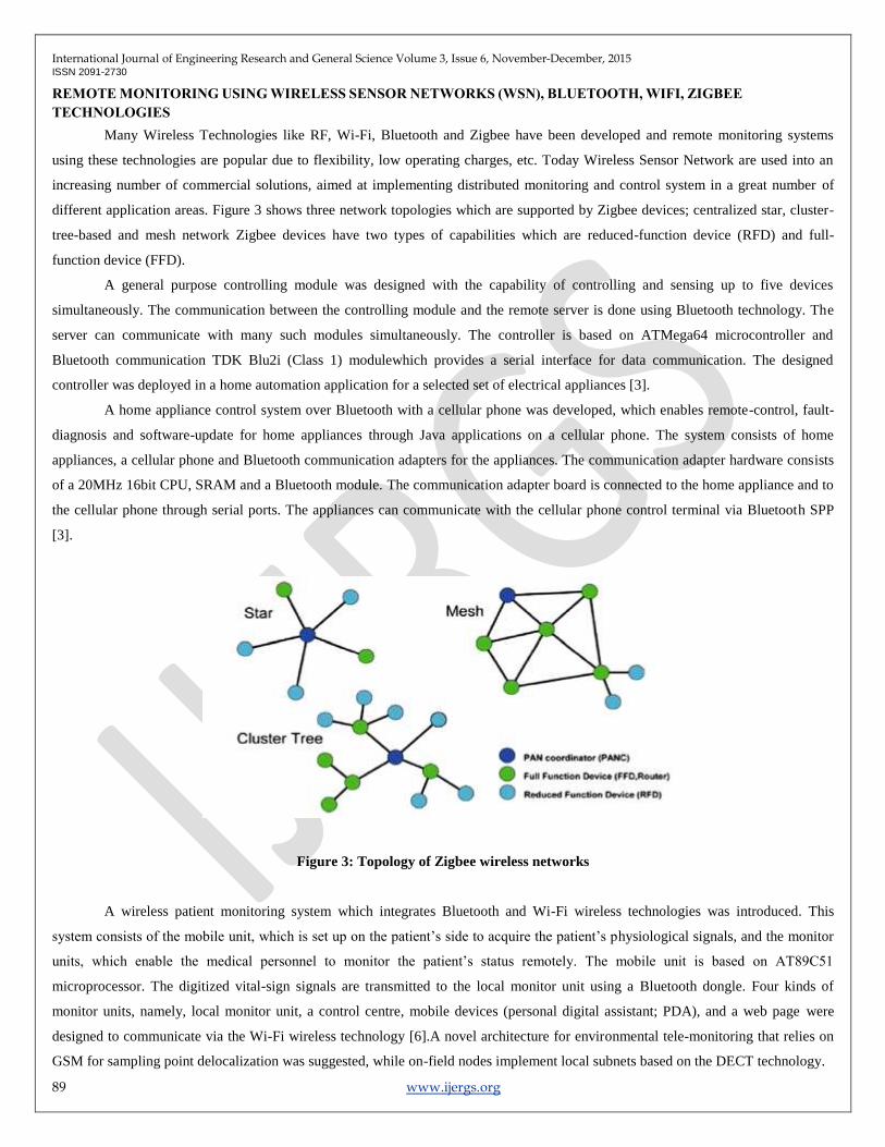
different application areas. Figure 3 shows three network topologies which are supported by Zigbee devices; centralized star, cluster-
tree-based and mesh network Zigbee devices have two types of capabilities which are reduced-function device (RFD) and full-
function device (FFD).
A general purpose controlling module was designed with the capability of controlling and sensing up to five devices
simultaneously. The communication between the controlling module and the remote server is done using Bluetooth technology. The
server can communicate with many such modules simultaneously. The controller is based on ATMega64 microcontroller and
Bluetooth communication TDK Blu2i (Class 1) modulewhich provides a serial interface for data communication. The designed
controller was deployed in a home automation application for a selected set of electrical appliances [3].
A home appliance control system over Bluetooth with a cellular phone was developed, which enables remote-control, fault-
diagnosis and software-update for home appliances through Java applications on a cellular phone. The system consists of home
appliances, a cellular phone and Bluetooth communication adapters for the appliances. The communication adapter hardware consists
of a 20MHz 16bit CPU, SRAM and a Bluetooth module. The communication adapter board is connected to the home appliance and to
the cellular phone through serial ports. The appliances can communicate with the cellular phone control terminal via Bluetooth SPP
[3].
Figure 3: Topology of Zigbee wireless networks
A wireless patient monitoring system which integrates Bluetooth and Wi-Fi wireless technologies was introduced. This
system consists of the mobile unit, which is set up on the patient’s side to acquire the patient’s physiological signals, and the monitor
units, which enable the medical personnel to monitor the patient’s status remotely. The mobile unit is based on AT89C51
microprocessor. The digitized vital-sign signals are transmitted to the local monitor unit using a Bluetooth dongle. Four kinds of
monitor units, namely, local monitor unit, a control centre, mobile devices (personal digital assistant; PDA), and a web page were
designed to communicate via the Wi-Fi wireless technology [6].A novel architecture for environmental tele-monitoring that relies on
GSM for sampling point delocalization was suggested, while on-field nodes implement local subnets based on the DECT technology.

International Journal of Engineering Research and General Science Volume 3, Issue 6, November-December, 2015 ISSN 2091-2730
90 www.ijergs.org
Table 2: Comparison of Bluetooth, WIFI, Zigbee
Table 2 explains the comparison of Bluetooth, Wi-Fi, Zigbee with respect to its range of distance, Number of nodes,
Frequency band, Data protection and power use.
A novel architecture for environmental tele-monitoring that relies on GSM for sampling point delocalization was suggested,
while on-field nodes implement local subnets based on the DECT technology. Local subnets contain two major blocks; Acquisition
Station (AS) where sensors and actuators are located and Transmitting Module (TM), i.e., the module that handles several
measurement stations and sends data to the control center (CC). Each AS acts as a data logger, storing in its internal memory device
field data; communications between AS and TM are cyclic (round robin), with a cycle time of about 1–10 min. On the contrary,
(personal digital assistant; PDA), and a web page were designed to communicate via the Wi-Fi wireless technology. Figure 4 shows
IBSS and ESS configuration of WI-FI networks consisting of distribution system.
Figure 4: IBSS and ESS Configuration of Wi-Fi networks
Design and instrumentation of variable rate irrigation, a wireless sensor network, and software for real-time in-field sensing
and control of a site-specific precision linear-move irrigation system was done. Field conditions were site-specifically monitored by
six in-field sensor stations distributed across the field based on a soil property map, and periodically sampled and wirelessly
transmitted to a base station. An irrigation machine was converted to be electronically controlled by a programming logic controller
(Siemens S7-226 with three relay expansion modules activated electric over air solenoids to control 30 banks of sprinklers) that
updates geo-referenced location of sprinklers from a differential Global Positioning System (GPS) (17HVS, Garmin) and wirelessly
Standard Range Number of Nodes Frequency Band Data Protection Power use
Bluetooth 10 m 8 2.4GHz 16-bit CRC High
Wi-Fi 100 m 32 3.1-10.6 GHz 32-bit CRC High
Zigbee 10-200 m More than 25400 868/915 MHz 2.4
GHz
16-bit CRC Low

International Journal of Engineering Research and General Science Volume 3, Issue 6, November-December, 2015 ISSN 2091-2730
91 www.ijergs.org
communicates with a computer at the base station. Communication signals from the sensor network and irrigation controller to the
base station were successfully interfaced using low-cost Bluetooth wireless radio communication through Bluetooth RS-232 serial
adaptor (SD202, Initium Company).Figure 5 shows power observing structure via Bluetooth, Ethernet and GSM.
Figure 5: Power Observing structure via Bluetooth, Ethernet and GSM
A WSN based system for monitoring a series of physiological parameters in the vineyard to prevent plant vine diseases was
developed. Sandy soils have very different behaviour to irrigation in respect to clayey ones; water retention capacity is completely
different and measuring it exactly where it is needed can help in controlling the irrigation system and saving water. Monitoring air
temperature and humidity in different parts of a vine can help in preventing and Fighting plants diseases, reducing the amount of
pesticides only when and where they are necessary.
The master node of the Wireless Sensor Network is connected to a GPRS gateway board, forwarding data to a remote server, using the
TCP-IP standard protocol. It included 11 nodes with a total of 35 sensors distributed on 1 hectare area; monitor common parameter
using simple, unobtrusive, commercial and cheap sensors.
Forwarding their measurements by the means of a heterogeneous infrastructure, consisting of WSN technology, GPRS
communication and ordinary Internet data transfer (TCP-IP protocol). Data coming from sensors are stored in a database that can be
queried by users everywhere in world, only using a laptop or a PDA: the Smart User Interface also allows to read and to analyze data
in an easy way. (Harms et al., 2010) describe the emerging wireless sensor networks (WSN) for autonomous Structural Health
monitoring SHM systems for bridges. In SmartBrick Network, the base station and sensor nodes collect data from the onboard and
external sensors. The sensor nodes communicate their data from quasi-static sensors, e.g., temperature sensors, strain gauges and
seismic detectors to the base station over the ZigBee connection. The base station processes these data and communicates them, along
with any alerts generated, to a number of destinations over the GSM/GPRS link provided by the cellular phone infrastructure. The data
are reported by email and FTP to redundant servers, via the Internet, at regular intervals or on an event-triggered basis. The alerts are
sent directly by SMS text messaging and by email. Wireless sensor networks are the key enabler of the most reliable and durable
systems for long-term SHM and have the potential to dramatically increase public safety by providing early warning of impending
structural hazards [1].

International Journal of Engineering Research and General Science Volume 3, Issue 6, November-December, 2015 ISSN 2091-2730
92 www.ijergs.org
Figure 6: Zigbee-based Transmission Line Monitoring
Forwarding their measurements by the means of a heterogeneous infrastructure, consisting of WSN technology, GPRS
communication and ordinary Internet data transfer (TCP-IP protocol). Data coming from sensors are stored in a database that can be
queried by users everywhere in world, only using a laptop or a PDA: the Smart User Interface also allows to read and to analyze data
in an easy way. (Harms et al., 2010) describe the emerging wireless sensor networks (WSN) for autonomous Structural Health
monitoring SHM systems for bridges. In SmartBrick Network, the base station and sensor nodes collect data from the onboard and
external sensors. The sensor nodes communicate their data from quasi-static sensors, e.g., temperature sensors, strain gauges and
seismic detectors to the base station over the ZigBee connection. The base station processes these data and communicates them, along
with any alerts generated, to a number of destinations over the GSM/GPRS link provided by the cellular phone infrastructure. The data
are reported by email and FTP to redundant servers, via the Internet, at regular intervals or on an event-triggered basis. The alerts are
sent directly by SMS text messaging and by email. Wireless sensor networks are the key enabler of the most reliable and durable
systems for long-term SHM and have the potential to dramatically increase public safety by providing early warning of impending
structural hazards [1].
A wireless medical interface based on ZigBee and Bluetooth technology. The purpose is to acquire, process, and transfer
raw data from medical devices to Bluetooth network. The Bluetooth network can be connected to PC or PDA for further processing.
The interface comprises two types of device: MDIZ and MDIZB. MDIZ acquires data from medical device, processes them using
microcontroller, and transmit the data through ZigBee network through UART. MDIZB receives data from several MDIZs and
transmit them out to PC through Bluetooth network. MDIZB comprises of ZigBee module, two processors, RAM, and Bluetooth
module. It receives data from ZigBee network through its ZigBee module is shown in Figure 6. The data are then sent to processor 1.
Processor 1 decides priority of MDIZs. In processor 1, the data frame is added with Start byte and End byte to mark the beginning and
the end of data frame. After being processed in processor 1, the data are then sent to processor 2 through SPI (Serial Peripheral
Interface). Processor 2 transmits data to PC throgh Bluetooth network [2]. Processor 2 controls Bluetooth module. It also receives
commands given by PC through Bluetooth network.
Table 3 explains the comparison of Bluetooth, Wi-Fi, Zigbee and UWB with respect to their Standards such as IEEE spec,
Frequency band, maximum signal rate, nominal range, nominal Tx power, number of RF channels, Channel bandwidth, modulation
type,spreading,co-existance mechanism, basic cell, extension of basic cell, maximum number of cell nodes , encryption, authentication
and Data protection.

International Journal of Engineering Research and General Science Volume 3, Issue 6, November-December, 2015 ISSN 2091-2730
93 www.ijergs.org
Table 3: Comparison of Bluetooth, UWB, Zigbee and Wi-Fi
Standard Bluetooth UWB Zigbee Wi-fi
IEEE spec 802.15.1 802.15.3a* 802.15.4 802.11a/b/g
Frequency band 2.4GHz 3.1-10.6GHz 868/915
MHz;2.4GHz
2.4GHz;5GHz
Max signal rate 1Mb/s 110Mb/s 250Kb/s 54Mb/s
Nominal range 10m 10m 10-100m 100m
Nominal Tx power 0-10 dBm -41.3dBm /MHz (-25)-0 dBm 15-20 dBm
Number of RF
channels
79 1-15 1/10;16 14(2.4GHz)
Channel bandwidth 1MHz 500 MHz-7.5GHz 0.3/0.6 MHz;2MHZ 22MHz
Modulation type GFSK BPSK;QPSK BPSK(+ASK), O-
QPSK
BPSK, QPSK
COFDM,CCK,OFDM
Spreading FHSS DS-UWB,MB-OFDM DSSS DSSS,CCK,M-QAM
Coexistence
mechanism
Adaptive
freq.
hopping
Adaptive freq. hopping Dynamic freq.
selection
Dynamic freq. selection,
transmit power control.
(802.11h)
Basic cell piconet Piconet star BSS
Extension of basic cell scattement Peer-to-peer Cluster tree, mesh ESS
Max number of cell
nodes
8 8 >65000 2007
Encryption E0 Stream
clipher
AES block clipher
(CTR counter mode)
AES block clipher
(CTR counter mode)
RC4 block clipher
(WEP) AES block clipher
Authentication Shared
secret
CBC-MAC(CCM) CBC-MAC(ext of
CCM)
WPA2(802.11i)
Data protection 16-bit
CRC
32-bit CRC 16-bit CRC 32-bit CRC
The interface is connected with four different medical devices through UART and analog port at 42 kbps of data rate. Table 3
explains the comparison of Bluetooth , UWB, Zigbee and Wi-Fi based on IEEE spec , frequency band, Nominal range, Channel
bandwidth, modulation type etc.
CONCLUSION
In this paper, Web-based wireless system for remote monitoring is presented. Besides having control function which can
monitor the system remotely, the system is also equipped with web-based function which made it accessible at any place and any time
via the internet. We use both wired and wireless networks for remote monitoring. Wired network has some limitations to which we
prefer wireless networks due to its reduced cabling costs and installation time. It lets you move your measuring device from place to
place and remotely monitor conditions. You can log data from your existing devices wirelessly by adding appropriate adaptors or
routers.
Here, from the above analysis we find both Wi-Fi and Zigbee are better than other monitoring systems. When data protection
is considered as first priority, Wi-Fi is preferred over Zigbee. Zigbee is preferred to other monitoring systems due to the advantages
such as security, long battery lifetime due to low duty cycle and low cost .It has large number of nodes up-to 65000 in a network. It is
easy to deploy and is used globally
International Journal of Engineering Research and General Science Volume 3, Issue 6, November-December, 2015 ISSN 2091-2730
94 www.ijergs.org
To improve on the monitoring system, some future works are suggested here. Firstly, the data obtained from the monitoring
system is useful for future reference to determine the efficiency and stability of the PV system as it may reduce over times. Secondly,
the data collected can also be used for fault detection. Thirdly, faulty notification to user by using messaging system may become an
added value to the system. Lastly, sensors failure detection may be added to the developed system to improve its robustness.
REFERENCES:
1. N. Javaid, A. Sharif, A. Mahmood, S. Ahmed, U. Qasim, Z. A. Khan ―Monitoring and Controlling Power using Zigbee
Communications‖ , Aug- 2012.
2. Jin-Shyan Lee, Yu-Wei Su, and Chung-Chou Shen ―A Comparative Study of Wireless Protocols: Bluetooth, UWB, ZigBee,
and Wi-Fi‖, Nov- 2007.
3. ViniMadan , S.R.N Reddy ―GSM-Bluetooth based Remote Monitoring and Control System with Automatic Light
Controller‖, Volume 46– No.1, May 2012.
4. Purnima, S.R.N. Reddy, PhD. ―Design of Remote Monitoring and Control System with Automatic Irrigation System using
GSM-Bluetooth‖,Volume 47– No.12, June- 2012.
5. Van Der Werff, M , ; Gui, X., Xu, W.L . ―A mobile-based home automation system‖, Nov-2005.
6. E. Ferro and F. Potorti, ―Bluetooth and Wi-Fi wireless protocols: A survey and a comparison‖, Volume 12, Issue 1, Pages 12-
26,Feb-2005.
7. Baker, N. ―ZigBee and Bluetooth: Strengths and weaknesses for industrial applications‖ Volume 16, Issue 2,Pages 20-25,
April-May 2005.
8. P. S. Neelakanta and H. Dighe, ―Robust factory wireless communications: A performance appraisal of the Bluetooth and the
ZigBee collocated on an industrial floor‖, 2003.
9. Cheng, J.Y. and Hung, M.H. and Chang, J.W., ―A Zigbee-based power monitoring system with direct load control
capabilities‖ , Pages 895-900,April-2007.
10. M. Gagliarducci, D.A. Lampasi, L. Podesta, ―GSM-based monitoring and control of photovoltaic power generation‖,
Volume 40, Issue 3, Pages 314–321, April-2007.
11. Jifeng Ding, JiyinZhao,Biao Ma, ―Remote monitoring system of temperature and humidity based on GSM ‖, Pages 1-4, Oct-
2009.
12. Stanley Liu, ―Overcoming IP Address Issues with GPRS Remote Monitoring and Alarm Systems‖, April-2009.
13. FarihahShariff , Nasrudin Abd Rahim , Hew Wooi Ping ―Zigbee-based data acquisition system for the online monitoring of
grid-connected photovoltaic system‖, Oct-2014.