
Comparison of Methods to Load a Mirror Magneto-Optical Trap Date: 14 May 2009 Author: C. Erin Savell...
26
Comparison of Methods to Load a Mirror Magneto-Optical Trap Date: 14 May 2009 Author: C. Erin Savell Advisors: Dr. Shaffer and Arne Schwettmann Acknowledgement: Jonathan Tallant, Adrienne Wade, Herbert Grotewohl, Ernest Sanchez Capstone Talk PHYS 4300
-
Upload
corey-wilkins -
Category
Documents
-
view
215 -
download
1
Transcript of Comparison of Methods to Load a Mirror Magneto-Optical Trap Date: 14 May 2009 Author: C. Erin Savell...

Comparison of Methods to Load a
Mirror Magneto-Optical Trap
Date: 14 May 2009Author: C. Erin SavellAdvisors: Dr. Shaffer and Arne SchwettmannAcknowledgement: Jonathan Tallant, Adrienne Wade, Herbert Grotewohl, Ernest Sanchez
Capstone Talk
PHYS 4300

Outline
•Motivation
•Atom Interferometry
•Magneto Optical Trap (MOT)
•Cooling and trapping transition
•Mirror MOT
•My work
o Measuring MOT characteristics
o Measuring MOT loading rates
o Discussion of results
•Questionshttp://weblogs.newsday.com/sports/watchdog/blog/satellite-radio.jpg
http://www.aerospaceweb.org/aircraft/fighter/f22/f22_09.jpg

Motivation
•To streamline MOT formation process; better MOTs
allow better atom chip experiments
•Atom chip allows faster, cheaper BEC (Bose-Einstein
Condensate) formation
o requires less equipment and gets steeper magnetic field
gradients
•Atom interferometry can beat current methods used
for inertial navigation by orders of magnitude, but
systems need to be compact

Graphic courtesy of H. Grotewohl
What is an Interferometer?
•Interferometer: instrument that separates beam of light into
two and recombines them resulting in an interference pattern
•Resulting pattern can be used to measure wavelength, index
of refraction, or astronomical distances (Measures Phase
shifts -> phase to intensity conversion)
•A high precision method
to measure speed of
light and acceleration

•Can be used for navigation gyroscope for inertial
guidance
o Will replace laser interferometers/gyroscopes
•Atom Interferometry more sensitive than with light =
BETTER
o Atoms move at finite speed << c
o Longer sampling time
o more time to experience inertial changes
Atom Interferometry: Why
Mirror assembly for laser interferometer
www.answers.com/topic/michelson-interferometer
Ring laser gyroscope
Fiber optic gyroscope
www.aerospaceweb.org/question/weapons/q0187.shtml

Atom Interferometry: How
•Atom well formed in MOT or
other similar means
•Radio frequency (RF) current
passed through a nearby wire
o Causes wavefunctions in trap to
change shape, spliting from
“single well” of atoms to “double
well”
•Atom wavefunctions recombine
o Absorption imaging can detect
resulting interference pattern
Graphic courtesy of H. Grotewohl
Atomic Wave Functions (split-> superposition)

MOT
Graphic courtesy of H. Grotewohl
Laser Orientation in a MOT
(red= laser)

PhotonΔP
Atom
ΔP
ΔP
Animation courtesy of Ernie Sanchez
MOT Animation

Mirror MOT
•Same principle as a basic MOT,
but uses a mirror to reflect the
laser
•Easier for trapping atoms near a
surface
•Provides good source of cold
atoms for loading of atom chip
microtraps
o Atom chips can be used as the mirror
in a mirror MOT
Schmiedmayer Paper, p. 4
Atom chip surface
Mirror MOT on atom chip (red= laser, gray=chip/mirror)
Graphic courtesy of H. Grotewohl

Cooling and Trapping Transitions of Rb-87
http://jilawww.colorado.edu/pubs/thesis/du/
•Cooling laser: red-detuned to compensate for Doppler
shift
•Repumping laser: recycles atoms from ground state
back into cooling transition

Our Mirror MOTImage courtesy of Arne Schwettmann
MOT
Future cooling block location Mirror
(or atom chip mount)
•Rb-85 atoms in mirror
MOT
•Located 4.8mm below
mirror surface
•No chip in chamber
yet; just mirror
•T=~200μK
•FWHM 1.6mm
vertically, 0.6mm
horizontally
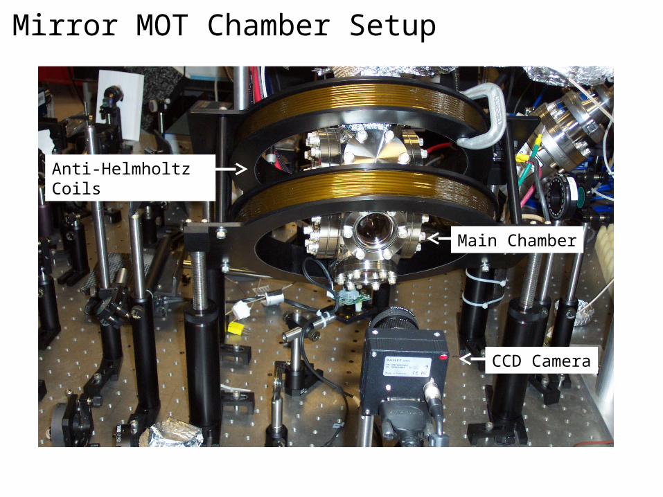
Mirror MOT Chamber Setup
CCD Camera
Main Chamber
Anti-Helmholtz Coils

Factors Affecting MOT Stability
•Background Pressure: ambient pressure inside
chamber
o Pressure too low -> smaller number of atoms in MOT
o Pressure too high -> increased atom collisions shorten MOT
lifetime by knocking atoms out of trap
•Laser Lock:
o Necessity to minimize signal noise
o Stable lock = stable MOT
o No lock = no MOT

Rubidium Source
Saes Getters S. p. A Catalog, p. 10
Image courtesy of Arne
Schwettmann
•Source controlled by current
•Normally ~5.3A
•Attaches by a mount on a
flange that has electrical feed-
throughs
•Releases Rb from solid state
to a gaseous state

My Work
•Goal: to make higher quality MOT
for loading chip trap
•Count number of atoms in MOT
o The more atoms the better
•Measure density of atoms in MOT
o Denser is better
•Measure loading rate of MOT
o Will compare rate and background
pressure of 3 different MOT loading
methods
MOT in Shaffer Lab
Image courtesy of Arne
Schwettmann
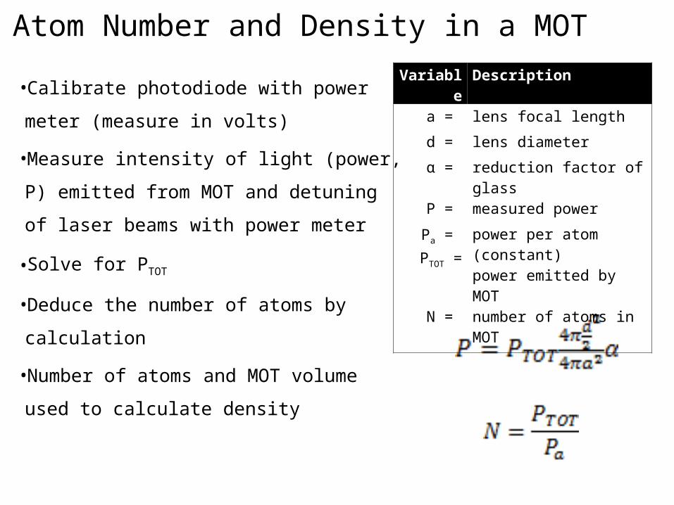
Atom Number and Density in a MOT
•Calibrate photodiode with power
meter (measure in volts)
•Measure intensity of light (power, P)
emitted from MOT and detuning of
laser beams with power meter
•Solve for PTOT
•Deduce the number of atoms by
calculation
•Number of atoms and MOT volume
used to calculate density
Variable Description
a = lens focal length
d = lens diameter
α = reduction factor of glass
P = measured power
Pa =
PTOT =
power per atom (constant)power emitted by MOT
N = number of atoms in MOT

Photodiode Calibration Setup
iris linear polarizer
beam splitter
beam direction
power meter
photo diode

MOT Loading Rate Measurement
•Fast loading rate and low background pressure are
goals
•Compare rates and background pressure of 3 loading
methods:
o Continuous: source on nonstop
o Pulsed: source pulsed on/off
o UV-LIAD (Ultra-violet Light Induced Adsorption Desorption):
UV lamp used to desorb Rubidium atoms from windows/sides
of chamber
Diode lasers from MOT setup

Building a UV LED Array for UV-LIAD
•Built UV-LED
array
•Assembled circuit
to support LED
array
•Tested circuit and
assembled it in
front of chamber
window
UV LED
array
circui
t

Rubidium Source Continuously “on”
•Utilizes lower current (~3A)
•Slower, more controlled loading rate
UV LIAD Rates
•Rubidium source switched off
•UV LED array switched on for entire loading period
•Rb atoms on chamber walls become excited, adsorb
from walls into gas, load MOT

Pulsed Source

Experimental Parameters•The laser lockpoint was maintained at δ =-
10.7±1.6MHz from the trapping transition 85Rb 5 S1/2� F
= 3 5 P3/2� F = 4
•Background pressure of chamber was maintained
near 2.0x10⁻¹⁰ TorrImage courtesy of Arne
SchwettmannF= 2 & 4 F= 3 & 4
F= 4

RESULTS

UV-LIAD, Continuous, and Background MOT Loading Methods•Background rate is
slowest
•UV-LIAD improves
atom number by
factor of 2
•Continuous source
best of the three
Background fitted curve
UV LIAD fitted curve
UV LIAD
Background pressure
Continuous
Continuous *Error in all data points measured is +/- 13%

Pulsed Source MOT Loading Methods
•10A current pulse
gives fastest loading
rate
o 10 times faster than
continuous, fastest
overall
•5A current half has
fast, twice as long,
smaller atom number
present in trap
2s pulse fitted curve
4s pulse fitted curve
4s pulse
2s pulse
*Error in all data points measured is +/- 13%

Questions?