COMPARISON OF I-GIRDER BRIDGE WITH DIFFERENT …ijseas.com/volume1/v1i5/ijseas20150549.pdf · ·...
12
International Journal of Scientific Engineering and Applied Science (IJSEAS) - Volume-1, Issue-5, August 2015 ISSN: 2395-3470 www.ijseas.com 435 PARAMETRIC STUDY AND COMPARISON OF I-GIRDER BRIDGE WITH DIFFERENT SUPPORT CONFIGURATION NAZIM SIDDIQUIP 1 P, YOGESH PATILP 2 P, ASHANT GAJBHIVP 3 P, SWALEHA SHIKALGARP 4 Under the Guidance of Prof. PRASHANT BARBUDE DATTA MEGHE COLLEGE OF ENGINEERING, AIROLI, NAVI MUMBAI ABSTRACT A study of I-girder with same cross-section, same number of support and same number of intermediate diaphragm but with 4 different support configurations is done. Commercial available software STAAD PRO has been used to carry out linear analysis of these I-girder bridges. Grillage method of analysis has been used to analyze the bridges. The linear analysis has been carried out for the dead load (self weight) and live load of Indian Road Congress (IRC) class 70R LOADING, CLASS A1 LOADING, CLASS A TWO LANE AND CLASS A FOUR LANE for eccentricity loading as per IRC is done. The paper presents a parametric study for deflection, bending and shear for different support configuration. It is found that the continuous span with equally spaced support is superior to other three support configuration. It can be stated that the obtained results will provide guidance to bridge designers. Keywords – I-GIRDERS; diaphragm; bending moment; shear force; support configuration. 1. INTRODUCTION I-Girder have gained wide acceptance in freeway and bridge system due to their structural efficiencies, better stability, serviceability, economy of construction and pleasing aesthetics. Analysis of prestress I- girder bridge is very complex because of its three dimensional behavior consisting of torsion, bending and shear. Diaphragms are used to connect all the girders at mid span and on the support to hold all the girders together which also reduces deflection. Greater span will give greater bending moment and thus depth of cross section will also increase and more amount of concrete and prestressing force will be required. While giving support configuration to a bridge one must take care that the difference between sudden changes in bending moment is not too high (that is no shooting moment). Thus the shear force will be less. 2. PROBLEM DEFINATION In the present work comparison of I-girder Bridge with four different support configuration namely:
-
Upload
duongthuan -
Category
Documents
-
view
217 -
download
2
Transcript of COMPARISON OF I-GIRDER BRIDGE WITH DIFFERENT …ijseas.com/volume1/v1i5/ijseas20150549.pdf · ·...

International Journal of Scientific Engineering and Applied Science (IJSEAS) - Volume-1, Issue-5, August 2015 ISSN: 2395-3470
www.ijseas.com
435
PARAMETRIC STUDY AND COMPARISON OF I-GIRDER BRIDGE WITH DIFFERENT SUPPORT CONFIGURATION
NAZIM SIDDIQUI P
1P, YOGESH PATIL P
2P, ASHANT GAJBHIV P
3P, SWALEHA SHIKALGAR P
4
Under the Guidance of Prof. PRASHANT BARBUDE
DATTA MEGHE COLLEGE OF ENGINEERING, AIROLI, NAVI MUMBAI
ABSTRACT
A study of I-girder with same cross-section, same number of support and same number of intermediate diaphragm but with 4 different support configurations is done. Commercial available software STAAD PRO has been used to carry out linear analysis of these I-girder bridges. Grillage method of analysis has been used to analyze the bridges. The linear analysis has been carried out for the dead load (self weight) and live load of Indian Road Congress (IRC) class 70R LOADING, CLASS A1 LOADING, CLASS A TWO LANE AND CLASS A FOUR LANE for eccentricity loading as per IRC is done.
The paper presents a parametric study for deflection, bending and shear for different support configuration. It is found that the continuous span with equally spaced support is superior to other three support configuration. It can be stated that the obtained results will provide guidance to bridge designers.
Keywords – I-GIRDERS; diaphragm; bending moment; shear force; support configuration.
1. INTRODUCTION
I-Girder have gained wide acceptance in freeway and bridge system due to their structural efficiencies, better stability, serviceability, economy of construction and pleasing aesthetics. Analysis of prestress I-girder bridge is very complex because of its three dimensional behavior consisting of torsion, bending and shear. Diaphragms are used to connect all the girders at mid span and on the support to hold all the girders together which also reduces deflection. Greater span will give greater bending moment and thus depth of cross section will also increase and more amount of concrete and prestressing force will be required. While giving support configuration to a bridge one must take care that the difference between sudden changes in bending moment is not too high (that is no shooting moment). Thus the shear force will be less.
2. PROBLEM DEFINATION
In the present work comparison of I-girder Bridge with four different support configuration namely:

International Journal of Scientific Engineering and Applied Science (IJSEAS) - Volume-1, Issue-5, August 2015 ISSN: 2395-3470
www.ijseas.com
436
a. 30-30-30m continuous span b. 30-30-30m simply supported span c. 25-40-25m continuous span d. 25-40-25m simply supported span
30 m 30 m 30 m
(a) 30M SIMPLY SUPPORTED
30 m 30 m 30 m
(b) 30-30-30M CONTINUOUS SUPPORTED
35 m 20 m 35 m
(c) 35-20-35M CONTINUOUS SUPPORTED
25 m 40 m 25 m
(d) 25-40-25 M CONTINUOUS SUPPORTED
The analysis of the bridge was done taking into consideration same area of cross section of I-girder and same length of bridge, that is 90 m. Also the number of support was kept same, that is four nos. The linear analysis has been carried out for the dead load (self weight) and live load of Indian Road Congress (IRC) class 70R LOADING, CLASS A loading for bridge using STAAD PRO. Deflection, bending moment, shear force was calculated and the comparison of four bridges has been done for various support configuration.
2.1 CROSS SECTION DETAILS
(a) (I-GIRDER WITH DECK) (b) (END DECK)
International Journal of Scientific Engineering and Applied Science (IJSEAS) - Volume-1, Issue-5, August 2015 ISSN: 2395-3470
www.ijseas.com
437
3. STAAD MODELLING AND DESCRIPTION
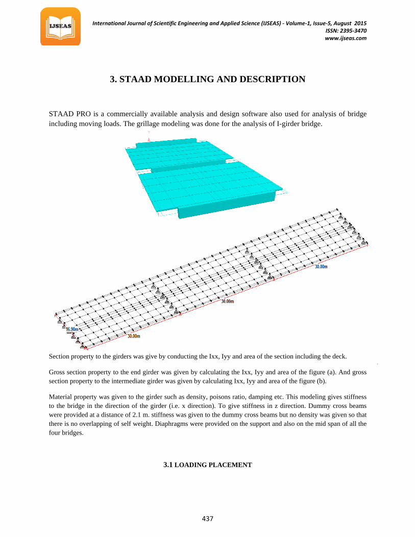
STAAD PRO is a commercially available analysis and design software also used for analysis of bridge including moving loads. The grillage modeling was done for the analysis of I-girder bridge.
Section property to the girders was give by conducting the Ixx, Iyy and area of the section including the deck.
Gross section property to the end girder was given by calculating the Ixx, Iyy and area of the figure (a). And gross section property to the intermediate girder was given by calculating Ixx, Iyy and area of the figure (b).
Material property was given to the girder such as density, poisons ratio, damping etc. This modeling gives stiffness to the bridge in the direction of the girder (i.e. x direction). To give stiffness in z direction. Dummy cross beams were provided at a distance of 2.1 m. stiffness was given to the dummy cross beams but no density was given so that there is no overlapping of self weight. Diaphragms were provided on the support and also on the mid span of all the four bridges.
3.1 LOADING PLACEMENT
International Journal of Scientific Engineering and Applied Science (IJSEAS) - Volume-1, Issue-5, August 2015 ISSN: 2395-3470
www.ijseas.com
438
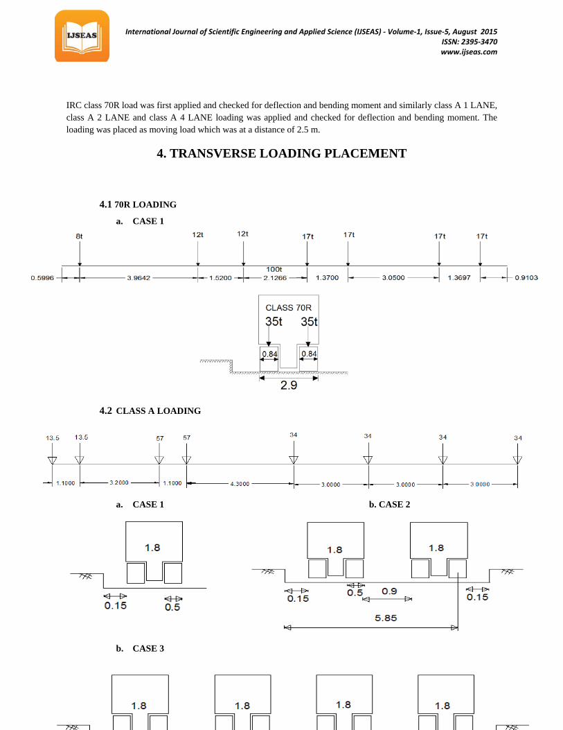
IRC class 70R load was first applied and checked for deflection and bending moment and similarly class A 1 LANE, class A 2 LANE and class A 4 LANE loading was applied and checked for deflection and bending moment. The loading was placed as moving load which was at a distance of 2.5 m.
4. TRANSVERSE LOADING PLACEMENT
4.1 70R LOADING
a. CASE 1
4.2 CLASS A LOADING
a. CASE 1 b. CASE 2
b. CASE 3

International Journal of Scientific Engineering and Applied Science (IJSEAS) - Volume-1, Issue-5, August 2015 ISSN: 2395-3470
www.ijseas.com
439
5. RESULTS AND COMPARISON
(Due to the limitation of space the results like BM, SF and Deflection of dead load at a particular section (L/2,L/4,L) bridge are represented graphically).
5.1 30-30-30M SIMPLY SUPPORTED
COMPARISON OF EXSTERNAL AND INTERNAL GIRDER FOR DEAD LOAD
PARAMETERS EXSTERNAL GIRDER (max.) INTERNAL GIRDER (max.) Deflection (mm) 28.45 28.43 Bending Moment (kN.m) 5268.73 5023.82 Shear Force (kN) 168 126 COMPARISON OF EXSTERNAL AND INTERNAL GIRDER FOR LIVE LOAD
PARAMETERS EXSTERNAL GIRDER INTERNAL GIRDER Deflection 18.89 12.62 Bending Moment 3488.4 2085.2 Shear Force 120 62.3
UEXTERNAL GIRDER:U UINTERNAL GIRDER:
LONGITUDINAL BENDING MOMENT LONGITUDINAL BENDING MOMENT

International Journal of Scientific Engineering and Applied Science (IJSEAS) - Volume-1, Issue-5, August 2015 ISSN: 2395-3470
www.ijseas.com
440
SHEAR FORCE SHEAR FORCE
From the above table & graphs it is observed that the difference between B.M & Deflection is quite less in both the cases i.e. dead load and live load. In case of dead load the S.F in external girder is moderately higher than the internal girder but in case of moving load the S.F in external girder is twice as that of internal girder.
5.2 30-30-30M CONTINUOUS SUPPORTED SPAN
COMPARISON OF EXSTERNAL AND INTERNAL GIRDER FOR DEAD LOAD
PARAMETERS EXSTERNAL GIRDER (max.) INTERNAL GIRDER (max.) Deflection (mm) 20.627 24.64 Bending Moment (kN.m) 5618.75 2789.78 Shear Force (kN) 215.2 129.96 COMPARISON OF EXSTERNAL AND INTERNAL GIRDER FOR LIVE LOAD
PARAMETERS EXSTERNAL GIRDER INTERNAL GIRDER Deflection 18.89 12.94 Bending Moment 3350.2 1030 Shear Force 140 58
UEXTERNAL GIRDERU UINTERNAL GIRDER
LONGITUDINAL BENDING MOMENT LONGITUDINAL BENDING MOMENT
International Journal of Scientific Engineering and Applied Science (IJSEAS) - Volume-1, Issue-5, August 2015 ISSN: 2395-3470
www.ijseas.com
441
SHEAR FORCE SHEAR FORCE
From the above table & graphs it can be observer that the B.M & S.F in the external girder is almost twice as that of internal girder. Whereas there is no great difference in deflection on the girders. In case of moving load the S.F, Deflection & B.M value of internal girder is less than the half of that of the external girder.
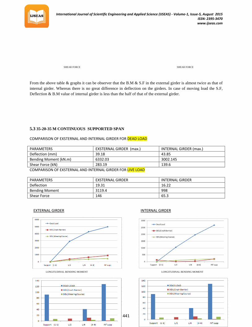
5.3 35-20-35 M CONTINUOUS SUPPORTED SPAN
COMPARISON OF EXSTERNAL AND INTERNAL GIRDER FOR DEAD LOAD
PARAMETERS EXSTERNAL GIRDER (max.) INTERNAL GIRDER (max.) Deflection (mm) 39.18 43.85 Bending Moment (kN.m) 6332.03 3002.145 Shear Force (kN) 283.19 139.6 COMPARISON OF EXSTERNAL AND INTERNAL GIRDER FOR LIVE LOAD
PARAMETERS EXSTERNAL GIRDER INTERNAL GIRDER Deflection 19.31 16.22 Bending Moment 3119.4 998 Shear Force 146 65.3
UEXTERNAL GIRDERU UINTERNAL GIRDER
LONGITUDINAL BENDING MOMENT LONGITUDINAL BENDING MOMENT
International Journal of Scientific Engineering and Applied Science (IJSEAS) - Volume-1, Issue-5, August 2015 ISSN: 2395-3470
www.ijseas.com
442
SHEAR FORCE SHEAR FORCE
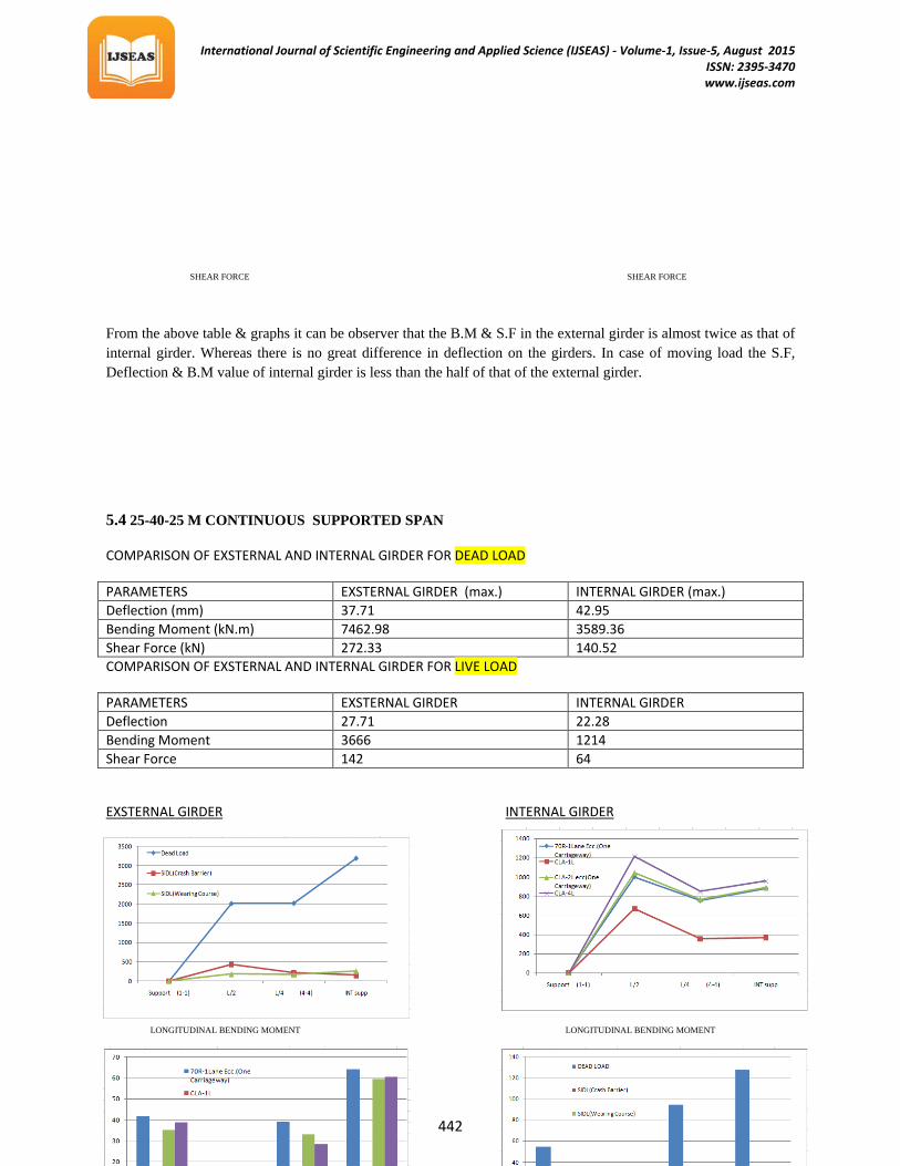
From the above table & graphs it can be observer that the B.M & S.F in the external girder is almost twice as that of internal girder. Whereas there is no great difference in deflection on the girders. In case of moving load the S.F, Deflection & B.M value of internal girder is less than the half of that of the external girder.
5.4 25-40-25 M CONTINUOUS SUPPORTED SPAN
COMPARISON OF EXSTERNAL AND INTERNAL GIRDER FOR DEAD LOAD
PARAMETERS EXSTERNAL GIRDER (max.) INTERNAL GIRDER (max.) Deflection (mm) 37.71 42.95 Bending Moment (kN.m) 7462.98 3589.36 Shear Force (kN) 272.33 140.52 COMPARISON OF EXSTERNAL AND INTERNAL GIRDER FOR LIVE LOAD
PARAMETERS EXSTERNAL GIRDER INTERNAL GIRDER Deflection 27.71 22.28 Bending Moment 3666 1214 Shear Force 142 64
UEXSTERNAL GIRDERU UINTERNAL GIRDER
LONGITUDINAL BENDING MOMENT LONGITUDINAL BENDING MOMENT

International Journal of Scientific Engineering and Applied Science (IJSEAS) - Volume-1, Issue-5, August 2015 ISSN: 2395-3470
www.ijseas.com
443
SHEAR FORCE SHEAR FORCE
From the above table & graphs it can be observer that the B.M & S.F in the external girder is almost twice as that of internal girder. Whereas there is no great difference in deflection on the girders. In case of moving load the S.F, Deflection & B.M value of internal girder is less than the half of that of the external girder.
6. COMPARISON OF SPANS
The comparison of different support configuration was done by comparing maximum values of shear force, Bending moment and Deflection of different spans. The below table gives a brief idea about the behavior of the bridge under different loading conditions.
6.1 EXTERNAT GIRDER:
PARAMETER LOAD TYPE 30 SIMPLY 30-30-30 CON. 35-20-35 CON. 25-40-25 CON. UCOMPARISON OF BENDING MOMENT
B.M.
DEAD LOAD 5268 4660 6332 7463
LIVE LOAD
70R 3488 3350 3119 2726 CL-A-1 1820 1708 2010 1805 CL-A-2 2956 2813 2982 2610 CL-A-4 2465 2571 2754 2421
DESIGN VALUE 8756 8010 9451 10189 UCOMPARISON OF SHEAR FORCE
S.F.
DEAD LOAD 268 245 283 273
LIVE LOAD
70R 120 140 146 142 CL-A-1 81 93 106 104 CL-A-2 98 116 135 129 CL-A-4 93 109 129 124
DESIGN VALUE 388 385 429 415 UCOMPARISON OF DEFLECTION
DF.
DEAD LOAD 28.45 20.62 39.18 37.71
LIVE LOAD
70R 18.89 16.05 19.30 26.00 CL-A-1 11.41 9.37 11.45 15.48 CL-A-2 17.06 14.53 18.1 27.71
International Journal of Scientific Engineering and Applied Science (IJSEAS) - Volume-1, Issue-5, August 2015 ISSN: 2395-3470
www.ijseas.com
444
CL-A-4 14.64 13.52 16.76 22.91
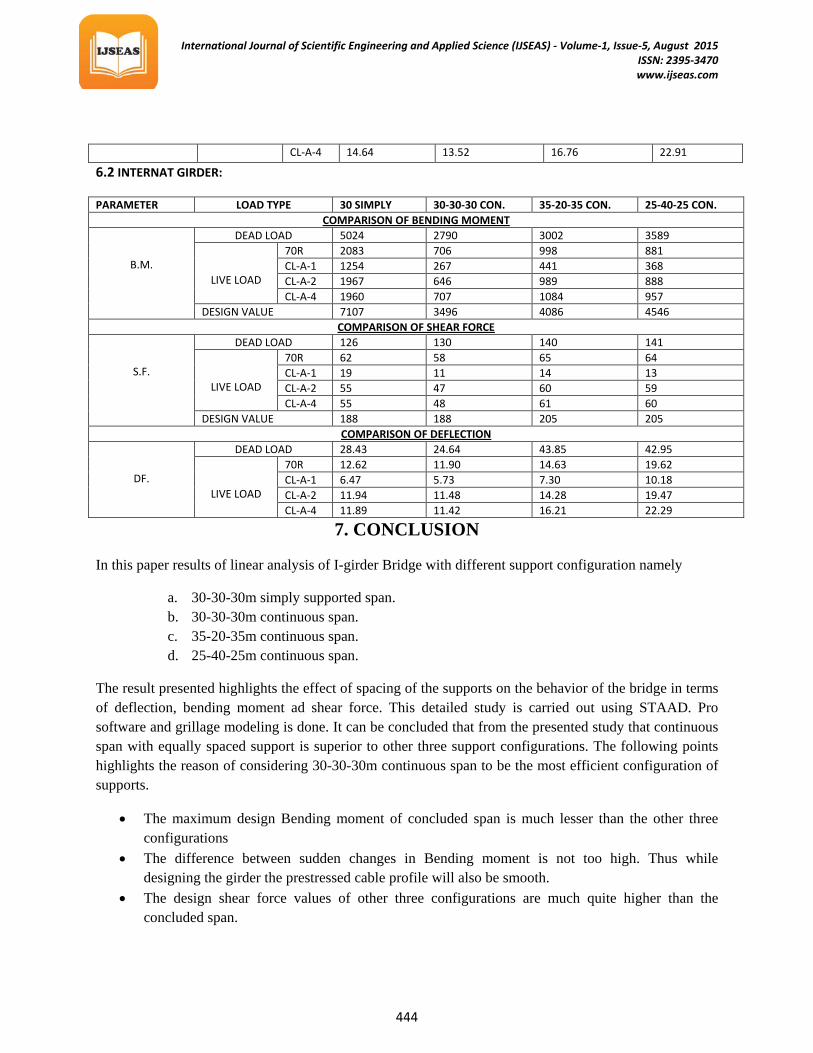
6.2 INTERNAT GIRDER:
PARAMETER LOAD TYPE 30 SIMPLY 30-30-30 CON. 35-20-35 CON. 25-40-25 CON. UCOMPARISON OF BENDING MOMENT
B.M.
DEAD LOAD 5024 2790 3002 3589
LIVE LOAD
70R 2083 706 998 881 CL-A-1 1254 267 441 368 CL-A-2 1967 646 989 888 CL-A-4 1960 707 1084 957
DESIGN VALUE 7107 3496 4086 4546 UCOMPARISON OF SHEAR FORCE
S.F.
DEAD LOAD 126 130 140 141
LIVE LOAD
70R 62 58 65 64 CL-A-1 19 11 14 13 CL-A-2 55 47 60 59 CL-A-4 55 48 61 60
DESIGN VALUE 188 188 205 205 UCOMPARISON OF DEFLECTION
DF.
DEAD LOAD 28.43 24.64 43.85 42.95
LIVE LOAD
70R 12.62 11.90 14.63 19.62 CL-A-1 6.47 5.73 7.30 10.18 CL-A-2 11.94 11.48 14.28 19.47 CL-A-4 11.89 11.42 16.21 22.29
7. CONCLUSION
In this paper results of linear analysis of I-girder Bridge with different support configuration namely
a. 30-30-30m simply supported span. b. 30-30-30m continuous span. c. 35-20-35m continuous span. d. 25-40-25m continuous span.
The result presented highlights the effect of spacing of the supports on the behavior of the bridge in terms of deflection, bending moment ad shear force. This detailed study is carried out using STAAD. Pro software and grillage modeling is done. It can be concluded that from the presented study that continuous span with equally spaced support is superior to other three support configurations. The following points highlights the reason of considering 30-30-30m continuous span to be the most efficient configuration of supports.
• The maximum design Bending moment of concluded span is much lesser than the other three configurations
• The difference between sudden changes in Bending moment is not too high. Thus while designing the girder the prestressed cable profile will also be smooth.
• The design shear force values of other three configurations are much quite higher than the concluded span.

International Journal of Scientific Engineering and Applied Science (IJSEAS) - Volume-1, Issue-5, August 2015 ISSN: 2395-3470
www.ijseas.com
445
• The deflection value is less in case of 30-30-30 continuous span while the deflection values of other three configurations are much higher.
It can also be believed that the result presented in this paper will be of valuable guidance to the designers.
8. REFERENCES
IRC: 2000 “DESIGN CRITERIA FOR PRESTRESSED CONCRETE ROAD BRIDGES (POST –TENSIONED CONCRETE)” THE INDIAN ROADS CONGRESS
IRC: 6-2000 “STANDARD SPECIFICATIONS AND CODE OF PRACTICE FOR ROAD BRIDGES” THE ROAD CONGRESS
KRISHANA RAJU “DESIGN OF BRIDGES” OXFORD AND IBH PUBLICATION CO.PVT.LTD” PROF. DR.ING.G.ROMBACH “CONCEPTS FOR PRESTRESSED CONCRETE BRIDGES PRESTRESSED CONCRETE : N KRISHANA RAJU IRC 112 (2011): CODE OF PRACTICE FOR CONCRETE ROAD BRIDGES. IS 6006-1993:INDIAN STANDARD SPECIFICATION FOR UNCOATED STRESS
RELIEVED STRAND FOR PRESTRESSED CONCRETE BRIDGE DESIGN USING THE STAAD.PRO/BEAVA AASHTO CODE COMPREHENSIVE DESIGN EXAMPLE FOR PRESTRESSED CONCRETE (PSC) GIRDER
SUPERSTRUCTURE BRIDGE WITH COMMENTARY (Task order DTFH61-02-T-63032)
ASIAN JOURNAL OF CIVIL ENGINEERING (BUILDING AND HOUSING) VOL. 11, NO. 1 (2010)

International Journal of Scientific Engineering and Applied Science (IJSEAS) - Volume-1, Issue-5, August 2015 ISSN: 2395-3470
www.ijseas.com
446
THANK YOU