Comparison of independent process analytical measurements — a

Comparison of an analytical study and EMTP implementationof complicated three-phase schemes for reactor interruptionCitation for published version (APA):Kalasek, V. K. I. (1988). Comparison of an analytical study and EMTP implementation of complicated three-phase schemes for reactor interruption. (EUT report. E, Fac. of Electrical Engineering; Vol. 88-E-204).Eindhoven: Eindhoven University of Technology.
Document status and date:Published: 01/01/1988
Document Version:Publisher’s PDF, also known as Version of Record (includes final page, issue and volume numbers)
Please check the document version of this publication:
• A submitted manuscript is the version of the article upon submission and before peer-review. There can beimportant differences between the submitted version and the official published version of record. Peopleinterested in the research are advised to contact the author for the final version of the publication, or visit theDOI to the publisher's website.• The final author version and the galley proof are versions of the publication after peer review.• The final published version features the final layout of the paper including the volume, issue and pagenumbers.Link to publication
General rightsCopyright and moral rights for the publications made accessible in the public portal are retained by the authors and/or other copyright ownersand it is a condition of accessing publications that users recognise and abide by the legal requirements associated with these rights.
• Users may download and print one copy of any publication from the public portal for the purpose of private study or research. • You may not further distribute the material or use it for any profit-making activity or commercial gain • You may freely distribute the URL identifying the publication in the public portal.
If the publication is distributed under the terms of Article 25fa of the Dutch Copyright Act, indicated by the “Taverne” license above, pleasefollow below link for the End User Agreement:www.tue.nl/taverne
Take down policyIf you believe that this document breaches copyright please contact us at:[email protected] details and we will investigate your claim.
Download date: 27. Mar. 2020

Comparison of an Analytical 'Study and EMTP I mplementation of .. = _
Complicated--Three-phase Schemes for Reactor Interruption by V.K.I. Kalasek
EUT Report 88-E-204 ISBN 90-6144-204-4
November 1988

ISSN 0167- 9708
Eindhoven University of Technology Research Reports
EINDHOVEN UNIVERSITY OF TECHNOLOGY
Faculty of Electrical Engineering
Eindhoven The Netherlands
COMPARISON OF AN ANALYTICAL STUDY
AND EMTP IMPLEMENTATION OF COMPLICATED
THREE-PHASE SCHEMES FOR REACTOR INTERRUPTION
by
V_K_I. Ka1asek
EUT Report 88-E-204
ISBN 90-6144-204-4
Eindhoven
November 1988
Coden: TEUEOE
CIP-GEGEVENS KONINKLIJKE BIBLIOTHEEK, DEN HAAG
Kalasek, V. K. I.
Comparison of an analytical study and EMTP implementation of complicated three-phase schemes for reactor interruption / by V.K.I. Kalasek. - Eindhoven: Eindhoven University of Technology, Faculty of Electrical Engineering. - Fig. - (EUT report, ISSN 0167-9708, 88-E-204) Met lit. opg., reg. ISBN 90-6144-204-4 SISO 661.5 UDC 621.311.1.015.3.001.57 NUGI 832 Trefw.: elektriciteitsnetten / elektrische overgangsverschijnselen.

- iii -
ABSTRACT When small inductive currents are interrupted by High Voltage circuit breakers current chopping will generally occur and will induce overvoltages. This paper describes a comparison between an analytical study and EMTP (= ElectroMagnetic Transient Program) implementation for calculation of such overvoltages in three-phase inductive circuits. Capacitive and/or inductive couplings between phases are included in schemes with grounded and non-grounded neutrals. If the time steps for numerical integration are small enough the EMTP calculation gives reliable and even more detailed and complete results than the analytical approach could do. Complete listing of input files for the EMTP program is given in the appendix.
Kalasek, V.K.I. Comparison of an analytical study and EMTP implementation of complicated three-phase schemes for reactor interruption. Faculty of Electrical Engineering, Eindhoven University of Technology, The Netherlands, 1988. EUT Report 88-E-204
Address of the author:
Or. ire V.K.I. Kalasek, Electrical Energy Systems Group, Faculty of Electrical Engineering, Eindhoven University of Technology, P.O. Box 513, 5600 MB Eindhoven. The Netherlands

- iv -
COIHENTS
1. Introduction
2. Analytical and EMTP-approach
1
1
3
4
5
3. Conclusion
References
Figures
EMTP-input:
Appendix A: Grounded reactors: 9 Non-coupled reactors 9 Capacitively coupled reactors 11 Mutually coupled reactors 13 Capacitively and mutually coupled reactors 15
Appendix B: Ungrounded reactors: 17 Non-coupled reactors 17 Capacitively coupled reactors 19 Mutually coupled reactors 21 Capacitively and mutually coupled reactors, Case A 23 Capacitively and mutually coupled reactors, Case B 25

- 1 -
Comparison of an analytical study and EMTP implementation
of complicated three phase schemes for reactor interruption.
1. Introduction
To find out how reliable the EMTP-computing program [1] is for solving
complicated transient situations the available results of an analytical
study of switching phenomena in three phase inductances (such as reactors)
were compared with the computations with EMTP.
Detailed mathematical expressions for current decays and voltage
transients derived by Van den Heuvel and Papadias can be found in [2] and
[3]. The analytical solution is rather complicated. The current is not
interrupted when passing the natural zero but a "current chopping" at a
small current value prior to zero occurs in most cases. After that the
magnetic energy still present in the interrupted inductance is being trans
ferred into the circuit capacitances causing a single- or multi-frequency
HF-oscillation. This oscillation penetrates into the other phases through
capacitive links and mutual coupl ings. These effects can cause very high
overvoltages in some circuits (depending on circuit parameters).
2. Analytical and EMTP-approach
The whole problem of current interrupting can be divided into four
time intervals:
1. time before the first phase interruption,
2. time interval between the first and the second phase interruption,
3. time interval between the second and the last phase interruption,
4. time after the last phase interruption.
The occurring phenomena are different during each of these intervals.
The frequencies of the occuring transient voltages accross the inductances
are different during the time intervals 2,3 and 4 while the amplitudes and
the shapes of the transients depend strongly on the value of the chopping
current. Boundary conditions have to be set for each phase at the beginning
of each of the intervals mentioned above. This makes the analytical solution
rather complex.

- 2 -
Four different situations have been studied by Van den Heuvel and
Papadias for the case of grounded reactors as well as for reactors without
grounded neutral:
1. non-coupled reactors.
2. capacitively coupled reactors,
3. inductively coupled reactors.
4. capacitively and inductively coupled reactors.
The amplitudes of transient overvoltages are strongly dependent on the
voltages and currents in other phases at the moment of the three successive
current choppings. To get seven different starting conditions (different
phase angles between 0 and 360 degrees at the moment of second phase inter
rupting in steps of 60 degrees) for each case mentioned above. small changes
of circuit parameters have been carried out.
For- the analytical solutions only the network frequency currents have
been used. In reality. however. the transient current oscillations after
first phase interruption also penetrate into the other phases. This results
in a small HF-oscl11ation superimposed on the network-frequency currents (as
shown in the third row of figures representing the current, expecially in
the phases B and C). The effect seems relatively small in the proximity of
current zero. where chopping occurs. But the phenomenon may have important
consequences when interrupting ungrounded inductances. as shown in [3]. It
is hardly possible to take the HF current oscillations into account in case
of analytical solution.
Another possible approach to solve the given problem is to use the
EMTP with only time-controlled switches. This way is much more reliable in
case of ungrounded inductances.
Both types of computations have been carried out at Eindhoven Univer
sity of Technology on the Burroughs B7900 computer of the Computing C~ntre.
Complete listing of input files for the EMTP implementation is given in the
appendix. The analytical method was used for grounded inductances. the EMfP
(version M35) for ungrounded ones. Later the EMfP version M39 was used on
the Apollo 3000 to verify the computations of grounded and ungrouned induc
tances.
The EMTP takes a different approach when solving the problem and it
takes the superposition of high frequency current components well. into
account. Both types of calculations were compared for a grounded circuit to
verify correct operation of the EMfP. Figures at the end of this article

give an example of
(analytical solution)
- 3 -
the results. Comparison of the first row of figures
with the second one (EMIP solution) shows the same
overall behaviour with only unimportant differences.
The only problem with the EMIP was to choose the time step for numeri
cal integration small enough so that. at the moment of current chopping. the
current would not change more than let say 5% of the given value of the
chopping current within two succeeding iterations. Therefore. the time step -6 At in our study had to be as small as 0.5 10 sec.
Mutually coupled R-L branch elements (ITYPE = 51. 52. 53) {for de
tailed information see the EMIP Rule Book [I]} were used in case of mutually
and mutually + capacitively coupled reactors.
For a complete review of all the sets of figures see [2] and [3].
Figures in Part I [2] were obtained by means of computation according to the
analytical formulas and checked with EMIP. while all the figures in Part II
[3] (for ungrounded reactors) are based on EMIP computation.
3. Conclusion
From this study the following could be concluded:
The analytical approach gives a better understanding of the whole
interrupting process and gives a clear explanation of such complicated
shapes of transient voltages. EMIP. however. gives more complete results
with all details considering all boundary conditions automatically. It is
much easier for the user when studying different situations of current
interruption to use the EMIP. Chance to make a mistake when putting in the
input variables is in that case also much smaller.
When comparing results obtained by using the exact analytical formulas
with the output of EMIP (version M35 as well as version M39) the full agree
ment in transient frequencies and amplitudes of overvoltages can be confir
med.

- 4 -
REFERENCES
[1] ElectroMagnetic Transients Program [EMTP]. Rule Book. Rev. version June 1984. Methods Development Branch, Route EDGB, Division of System Engineering, Bonneville Power Administration, P.O. Box 3621, Portland, Oregon 97208, USA. More information on EMTP can be obtained at:
EMTP European Users Group, K.U. Leuven EMTP Center, Kard. Mercierlaan 94, B-3030 Heverlee, Belgium
[2] Heuvel, W.M.C. van den and B.C. Papadias Interaction between phases in three phase reactor switchin9. Part 1: Grounded reactors. Electra (Paris), No. 91(1984), p. 11-50.
[3] Heuvel, W.M.C. van den and B.C. Papadias Interaction between phases in three phase reactor switchinq. Part 2: Ungrounded reactors. Electra (Paris), No. 112(1987), p. 57-81.

7.
-35
,. w
'" CO
'" '"
'" CO
'" .q
~ '" IS>"! it",
'" CO
"iD
'" '" .. '" .. CO .q ,
'" .. <So
'" ,
'" <SO
v
I
•
! ! I I!.
00 1. 60 3. , rl ' ,
03/21/85 17.16.22 PI or TYPE
- J -
•
Analytical solution
Voltage phase A
•
EM'l'P sOlUtion
Voltage phase A
1 •
.... 12
1 .(9
6.00

7.
J'
-J'
co
- 6
Analytical solution
Voltage phase B
~. -, ·7' .;-~C-__________________ ~ ________________________ ~ ________________________ ~ ____________________ ~ ... ~ _t JI • e J2
'"
EMTP solution
Voltage phase B
"':+-______ ~------~------~~----~------~-----.~~++~++~~~~~++~I4+~~~h "Il.0B 1.60 3.20 .~0 6.40 8.~0 ~ 61 II. 4 /!.B0
.. .. '" 4
.. .. .. '" ,
'" '" '" '" ,
03/21/85 17.16.22 PLOT TYPE 1 NOOE NAMES PUNT6
3
MILLI~ECO~DS I 01 i, I

"
"
, .. , -,. '-----------~------.. .
.. .. "'Il .00 3.20 4.80
M .. .. .. '" .. .. ~ ,
'" .. '"
.. 03/21/85 17.16.22 2
'" PLOT TYPE .. ., NODE NAMES PUNT4 ,
v
•
Analytical solution
Voltage phase C
EMTP solutior.
Voltage phase C
0
I I .
.... • 1Z
1 ~tl ", h 1 I j . 1 i \ r. ~
. I'l~ r

'" '" '" '"
'" '" '" '"
'" '" '" ¢
- '" <Sl'" ~.; <N
'" '"
~l
~l ! ~J
I
CUrrent phase B
MUTUALY RND CRPRCITIVELY COUPLED RERCTORS
.----- r·-- I - I . I r • !.6~ 3.20 4.8~ 6.40 8.~~ 9.~0
MILL ISECGr~DS
\ / ~. /
a3/2118S !7.16.'t~6 J
/ PLOT TYPE 9 NODE NRMES PUNTS UNT6
CUrrent phase C
I I
MUTURLY RND CRPRCITIVELY COUPLED RERCTORS
~,
r~~- i'.6~ !
l.20 4'.80 6·.43 8'.00 MILLISECONDS
i I
I I I I ')':') ,-.. Inr 17.16.22 5
I 'JI/'-l'U~
)L,OT TYPE 9 ., NODE NAMEs PUNT3 PUNT4 "'.'
9.60
co I

- 9 -
Appendix A - 1
BEGIN NEW DATA CASE C W.M.C. VAN DEN IIEUVEL. B.C. PAPADIAS : C INTERACTION BETWEEN PHASES IN TIlREE-PIIASE REACTOR SWI1UUNG C PART I : GROUNDED REACTORS C NON-<X>UPLED REACTORS C Electra No 91. C C C C C
U = 29.4 kV / / 138.0 mil
C C C C C C
+----: U :-----0/ o-----------------------------o-----LLLLL-----+ 1
U = 29.4 kV / /
2
138.0 mil C C C C C
0----: U. : -----0/ o------------------o----------I-----LLLLL-----o 3
C U = 29.4 kV
0----: U :-----0/ 5
/ /
4
138.0 mil 0-------0----------:---------- -----LLLLL-----o 6 +---0 +----0 +----0
C C C C C :10 nF: :10 nF: :10 nF C C C C C
: <XXrep R R
240k R R
:240k R R
R :240k R
R
C C
+-----------------------0---0-----0----0-----0----0---------------+
C C C POWER FREQUENCY CHANGE PRINTOUT FREQUENCY
6000 10 C 1ST MISC. DATA CARD C DELTAT TMAX XOPT
.50E-06 .16E-01 0.0 C 2ND MISC. DATA CARD
CDPT 0.0
50.0
C lOUT IPLOT lOOUBL KSSOUf MAXOUf 50 5 1 1 1
C BRANQI CARDS: C BUS 1 BUS2
PUNT2 PUNT4 PUNT6
R L 138.00 138.00 138.00
///
lPUN MEMSAV lCAT NENERG o 0 2 0
C
IPRSUP
OUTPUT o o o

PUNT2 PUNT4 PUNT6 PUNT2 PUNT4 PUNT6
. 240E6
. 240E6
. 240E6
BLANK CARD ENDING BRAOI CARffi C SWITOI CARffi: C BUS 1 BUS2 TCLOSE TOPEN
PUNTI PUNT2 -. l000E-OI .1000E-02 C BUSI BUS2 TCLOSE TOPEN
PUNT3 PUNT4 -.I000E-ol .1000E-02 C BUS 1 BUS2 TCLOSE TOPEN
-10-
.01000
.01000
.01000
IOIOP . 7670E+Ol
IOIOP . 7670E+Ol
IOIOP PUNT5 PUNT6 -.I000E-Ol .1000E-02 .7670E+Ol
BLANK CARD ENDING SWITOI CARffi C SOURCE CARffi: C TYPE BUS V /C AMPL FREQ TNUL 14PUNTI 1-.2939E+05 .5000E+02 0.0 C TYPE BUS V /C AMPL FREQ TNUL 14PUNT3 1-.2939E+05 .5000E+02 .1200E+03 C TYPE BUS V /C AMPL FREQ TNUL 14PUNT5 1-.2939E+05 .5000E+02-.1200E+03 BLANK CARD ENDING SOURCE CARffi C OIITPUT REQUFSf CARffi:
PUNT2 PUNT4 PUNT6 BLANK CARD ENDING OIITPUT REQUEST CARffi C PUYITER REQUEST CARffi: C METRIC SCALE:
SCALE CALCX>MP PLOT
C FIG. 1 C HEADING
2NON-<XlUPLED REACTORS 114
C HS
1.270025
Al
Al
Al
Appendix A - 2
TSTART -.I000E+02
TSTART -.I000E+02
TSTART -.I000E+02
VOLTAGE
o o o o o o
OUTPUT 1
OUTPUT 1
OUTPUT 1
TSTOP .1000E+02
TSTOP .1000E+02
TSTOP .1000E+02
HMAX VMIN VMAX . 1200000000E+Ol
PUNT2 HMIN 0.0 . 1200000000E+02-. SOOOOOOOOOE+05 .8000000000E+05
C FIG. 2 C HEADING
2NON-<XlUPLED REACTORS 114
C lIS . 1200000000E+Ol
C FIG. 3 C HEADING
2NON-<XlUPLED REACTORS
PUNT4 HMIN 0.0
VOLTAGE HMAX VMIN VMAX
. 1200000000E+02-. SOOOOOOOOOE+05 . SOOOO:JOOOOE+05
114 PUNT6 VOLTAGE C HS HMIN HMAX VMIN VMAX
. 1200000000E+Ol 0.0 .1200000000E+02-.SOOOOOOOOOE+05 .SOOOO:JOOOOE+05 BLANK CARD TERMINATING PWITER REQUESTS BEGIN NEW DATA CASE BLANK CARD ENDING TOTAL EMTP INPUT

- 11 -
Appendix A - 3
BEGIN NEW DATA CASE C W.M.C. VAN DEN HEUVEL, B.C. PAPADIAS : C INTERACTION BETWEEN PHASES IN THREE-PHASE REACTOR SWllUIING C PART I : GROUNDED REACTORS C CAPACITIVELY <XlUPLED REACTORS C Electra No 91 p. 35 fig. 4.14 case A C C C C C C C
7 +---0-----0----0-----0----+
267k R : 267k R : 267k R R R R
C C C C C C C C C
U = 29.4 kV I I
R :9 nF R :9 nF R : CCCCCl CCCCCl
9nF CCCCCl
C C C C C C C C C C C C C
+----: U :-----0/ 1
U = 29.4 kV I I
0----: U 1-----0/ 3
U = 29.4 kV I I
0----: U :-----0/ 5
+---0 +----0 +----0 138.00 mH o-------'----------:----------o-----LLLLL-----+ 2
138.00 mH 0------- ----------o----------'-----LLLLL-----o 4
138.00 mH 0-------0---------- ----------o-----LLLLL-----o 6 +---0 +----0 +----0
:10 nF: :10 nF: :10 nF : CCCCCp CCCCCp CCCCCp R R R
C C C
240k R : 240k R : 240k R R R R
C C C
+-----------------------0---0-----0----0-----0----0---------------+
C C POWER FREQUENCY mANGE PRINTOUf FREQUENCY
6000 10
III
50.0
C 1ST MISC. DATA CARD C DELTAT TMAX XOPT
.50E-06 ·.16E-01 0.0 C 2ND MISC. DATA CARD
OOPT 0.0
C lOOf IPLOf lOOUBL KSSOUT MAXOur 50 5 1 1 1
C BRANCH CARDS: C BUS1 BUS2
PUNT2 PUNT4 PUNT6
R L 138.00 138.00 138.00
lPUN MEMSAV lCAT NENERG o 0 2 0
C
IPRSUP
OOfPUf o o o
PUNT2 PUNT7 PUNT4 PUNT7 PUNT6 PUNT7 PUNT2 PUNT7 PUNT4 PUNT7 PUNT6 PUNTI PUNT2 PUNT4 PUNT6 PUNT2 PUNT4 PUNT6
.261£6
.261£6
.261£6
.240£6
. 240E6
. 240E6
BLANK CARD ENDING BRAClI CARDS C SWITaI CARDS: C BUS I BUS2 TCLOSE TOPEN
PUNTI PUNT2 -.loooE-OI .loooE-02 C BUSI BUS2 TCLOSE TOPEN
PUNT3 PUNT4 -.loooE-OI .loooE-02 C BUS I BUS2 TCLOSE TOPEN
PUNT5 PUNT6 -.loooE-01 .loooE-02 BLANK CARD ENDING SWITaI CARDS C SOURCE CARDS:
- 12 -
.00900
.00900
.00900
.01000
.01000
.01000
IaIOP .1740E+02
IaIOP .1740E+02
IaIOP . 1740E+02
C TIPE BUS V /C AMPL FREQ TNUL 14PUNTI 1-.2939E+05 .5OOOE+02 0.0 C TIPE BUS V /C AMPL FREQ TNUL 14PUNT3 1-.2939E+05 .5OOOE+02 .1200E+03 C TIPE BUS V /C AMPL FREQ TNUL 14PUNT5 1-.2939E+05 .5OOOE+02-.1200E+03 BLANK CARD ENDING SOURCE CARDS C OUTPUT REQUEST CARDS:
PUNT2 PUNT4 PUNT6 BLANK CARD ENDING OUTPUT REQUEST CARDS C PLOTI'ER REQUEST CARDS: C METRIC SCALE:
SCALE CALCDMP PLOT
C FIG. I C HEADING
1.270025
2CAPACITIVELY CDUPLED REACTORS 114 PUNT2
C HS HMIN
Al
Al
Al
Appendix A - 4
TSTART -.loooE+02
TSTART -.IOOOE+02
TSTART -.loooE+02
VOLTAGE
o o o o o o o o o o o o
OtrrPUT 1
OUTPUT I
OUTPUT 1
TSTOP .. loooE+02
TSTOP .loooE+02
TSTOP .loooE+02
HMAX YMIN VMAX .1200000000E+OI 0.0 • 1200000000E+02-. 8OOOOOOOOOE+05 .8000000000E+05
C FIG. 2 C HEADING
2CAPACITIVELY CDUPLED REACTORS 114 PUNT4 VOLTAGE
C HS HMIN HMAX YMIN VMAX .1200000000E+OI 0.0 .1200000000E+02-.8000000000E+05 .80000)ooooE+05
C FIG. 3 C HEADING
2CAPACITIVELY CDUPLED REACTORS 114 PUNT6 VOLTAGE
C HS HMIN HMAX YMIN VMAX .1200000000E+OI 0.0 .1200000000E+02-.8000000000E+05 .80000)ooooE+05
BLANK CARD TERMINATING PLOTI'ER REQUESTS BEGIN NEW DATA CASE BLANK CARD ENDING TOTAL EMTP INPUT

- 13 -
Appendix A - 5
BEGIN NEW DATA CASE C W.M.C. VAN DEN HEUVEL, B.C. PAPADIAS : C INTERACTION BETWEEN PHASES IN TIIREE-PHASE REACTOR SWI1UUNG C PART I : GROUNDED REACTORS C IIllTIJAL Y CXJUPLED REACTORS C Electra No 91 p. 48 fig 4.21 case A C C C C C C U = 29.4 kV I C I 105.80 mil C +----: U :-----0/ o-----------------------------o-----LLLLL-----+ C 1 2 C C M M C U = 29.4 kV I C I 105.80 mil C 0----: U :-----0/ o------------------o-----:----'-----LLLLL-----o C 3 4 C C M C U = 29.4 kV I C I 105.80 mil C 0----1 U :-----0/ o-------o----------:----------,-----LLLLL-----o C 5 6 +---0 +----0 +----0 C :to nF: :10 nF: :10 nF C : axxx;p axxx;p <XX:rep C R R R C 240k R :240k R :240k R C R R R C C +-----------------------0---0-----0----0-----0----0---------------+ C C C III C POWER FREQUENCY 50.0 aIANGE PRINTOOf FREQUENCY
6000 10 C 1ST MISC. DATA CARD C DELTAT TMAX XOPT <XlPT
.50E-06 .16E-01 0.0 0.0 C 2ND MISC. DATA CARD C lOUT IPWf lDOUBL KSSOUr MAXOUf lPUN MEMSAV lCAT NENERG IPRSUP
50 5 1 1 100 2 0 C BRANOI CARDS: C BUS1 BUS2 R L C OUTPUT 51PUNT2 105.8 52PUNT4 -32.2 105.8 53PUNT6 -32.2 -32.2 105.8

PUNT2 PUNT4 PUNT6 PUNT2 PUNT4 PUNT6
. 24OE6
. 24OE6
. 24OE6
BLANK CARD ENDING BRACH CARDS C SWITaI CARDS: C BUSI BUS2 TCLOSE TOPEN
PUNTI PUNT2 -.I000E-Ol .1000E-02 C BUSI BUS2 TCLOSE TOPEN
PUNT3 PUNT4 -.I000E-Ol .1000E-02 C BUS 1 BUS2 TCLOSE TOPEN
- 14 -
.01000
.01000
.01000
ICHOP . 154OE+02
ICHOP . 154OE+02
ICHOP PUNT5 PUNT6 -.I000E-01 .1000E-02 .154OE+02
BLANK CARD ENDING SWITCH CARDS C SOURCE CARDS: C TYPE BUS V /C AMPL FREQ TNUL 14PUNTI 1-.2939E+05 .5000E+02 0.0 C TYPE BUS V /C AMPL FREQ TNUL 14PUNT3 1-.2939E+05 .5000E+02 .1200E+03 C TYPE BUS V /C AMPL FREQ TNUL 14PUNT5 1-.2939E+05 .5000E+02-.12ooE+03 BLANK CARD ENDING SOURCE CARDS C OUTPUT REQUEST CARDS:
PUNT2 PUNT4 PUNT6 BLANK CARD ENDING OUTPUT REQUEST CARDS C PWITER REQUEST CARDS: C METRIC SCALE:
SCALE CALCOMP PLOT
C FIG. 1 C HEADING
1.270025
2MlJfUALY COUPLED REACI'ORS 114 PUNT2
C HS HMIN
Al
At
Al
Appendix A - 6
TSTART -.I000E+02
TSTART -.I000E+02
TSTART -.I000E+02
VOLTAGE
o o o o o o
OUTPUT 1
OUTPUT 1
OUTPUT 1
TSTOP .1.000E+02
TSTOP .1000E+02
TSTOP .1000E+02
HMAX VMIN VMAX . 1200000000E+Ol 0.0 .1200000000E+02-.SOOOOOOOOOE+05 .8oooo00000E+05
C FIG. 2 C HEADING
2MlJfUALY roUPLED REACI'ORS 114 PUNT4
C HS HMIN HMAX VOLTAGE
VMIN VMAX .1200000000E+Ol 0.0 . 1200000000E+02-. SOOOOOOOOOE+05 .8oooo000ooE+05
C FIG. 3 C HEADING
2MlJfUAL Y COUPLED REACI'ORS 114 PUNT6 VOLTAGE
C HS HMIN HMAX VMIN VMAX . 1200000000E+Ol 0.0 .1200000000E+02-.SOOOOOOOOOE+05 .8oooo000ooE+05
BLANK CARD TERMINATING PLOTTER REQUFSfS BEGIN NEW DATA CASE BLANK CARD ENDING TOTAL EMTP INPUT
- 15 -
Appendix A - 7
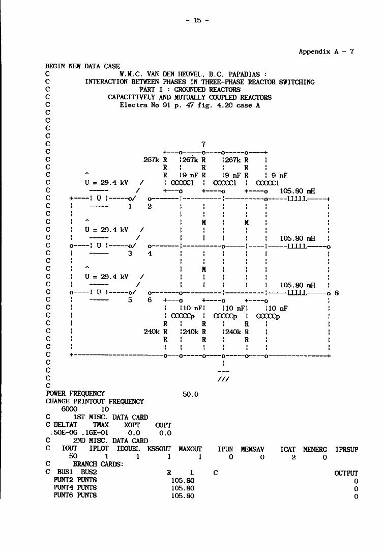
BEGIN NEW DATA CASE C W.M.C. VAN DEN IIEUVEL. B.C. PAPADIAS : C INTERACTION BETWEEN PHASES IN THREE-PHASE REACTOR SWI1UUNG C PART I : GROUNDED REACTORS C CAPACITIVELY AND MUTUALLY a>UPLED REACTORS C Electra No 91 p. 47 fig. 4.20 case A C C C C C C C C C
U = 29.4 kV
7 +---o--~--o----o-----o----+
267k R : 267k R : 267k R
/ /
R R R R :9 nF R :9 nF R : axxx::1 axxx::1
9 nF axxx::1
+---0 +----0 +----0 105.80 mH C C C C C C
+----: U :-----0/ o-------l----------:----------o-----LLLLL-----+
C C C C C C
1
U = 29.4 kV / /
0----: U :-----0/ 3
U = 29.4 kV / /
2
M M
105.80 mH , , o-------I----------o-----:----'-----LLLLL-----o 4
M
105.80 mH C C C C C C
0----: U :-----0/ 0-------0----------1---------- -----LLLLL-----o 8 5 6 +---0 +----0 +----0
C C C C
:10 nF: : axxx::p R
240k R R
R :240k R
R
:10 nF:
R :240k R
R
:10 nF
C C C
+-----------------------0---0-----0----0-----0----0---------------+
C C POWER FREQUENCY aIANGE PRINTOUf FREQUENCY
6000 10 C 1ST MISC. DATA CARD C DELTAT TMAX XOPT
.5OE-06 .16E-Q1 0.0 C 2ND MISC. DATA CARD
aJPT 0.0
50.0
C lOUT IPLOT lDOUBL KSSOUT MAXOUT 50 1 1 1 1
C BRANOI CAIIDS: C BUS1 BUS2
PUNT2 PUNTS PUNT4 PUNTS PUNT6 PUNTS
R L 105.80 105.80 105.80
///
lPUN MEMSAV lCAT NENERG o 0 2 0
C
IPRSUP
OUTPUT o o o

- 16 -
Appendix A - 8
PUNT2 PUNT7 PUNT4 PUNT7 PUNT6 PUNT7 PUNT2 PUNT7 PUNT4 PUNT7 PUNT6 PUNT7 PUNT2 PUNT4 PUNT6 PUNT2 PUNT4 PUNT6
.267E6
.261£6
.261£6
.240E6
.240E6
. 240E6
.00900
.00900
.00900
.01000
.01000
.01000 PUNTS -32.09
BLANK CARD ENDING BRACH CARffi C SWITCH CARffi: C BUSI BUS2 TCLOSE TOPEN
PUNTI PUNT2 -. l000E-OI .1000E-Q2 C BUSI BUS2 TCLOSE TOPEN
PUNT3 PUNT4 -.I000E-Ol .1000E-02 C BUS 1 BUS2 TCLOSE TOPEN
PUNT5 PUNT6 -.I000E-Ol .1000E-02 BLANK CARD ENDING SWITCH CARffi C SOURCE CARffi:
ICIIOP . 1770E+02
IaIOP . 1770E+02
ICHOP . 1770E+02
C TYPE BUS V /C AMPL FREQ TNUL 14PUNTI 1-.2939E+05 .5000E+02 0.0 C TYPE BUS V /C AMPL FREQ TNUL 14PUNT3 1-.2939E+05 .5000E+02 .12OOE+03 C TYPE BUS V /C AMPL FREQ TNUL 14PUNT5 1-.2939E+05 .5000E+02-.12OOE+03 BLANK CARD ENDING SOURCE CARffi C OUfPlIT REQUEST CARffi:
PUNT2 PUNT4 PUNT6 BLANK CARD ENDING OUfPlIT REQUFST CARffi C PWITER REQUEST CARffi: C METRIC SCALE:
SCALE CAL<.XlMP PLOT
C FIG. 1 C HEADING
1.270025
2MlITUALY AND CAPACITIVELY COUPLED REACfORS
Al
Al
Al
TSTART -.I000E+02
TSTART -.I000E+02
TSTART -. l000E+02
114 PUNT2 VOLTAGE C lIS HMIN HMAX VMIN
o o o o o o o o o o o o o
OUTPUT 1
OUTPlIT 1
OUTPlIT 1
TSTOP .1000E+02
TSTOP . l000E+02
TSTOP .1000E+02
. 1200000000E+Ol 0.0 .1200000000E+02-.8000000000E+05 .8000000000E+05 C FIG. 2 C HEADING
2MlITUALY AND CAPACITIVELY COUPLED REACfORS 114 PUNT4 VOLTAGE
C lIS HMIN HMAX VMIN VMAX . 12()()()()oo()()E+Ol 0.0 .1200000000E+02-.8000000000E+05 .8000000000E+05
C FIG. 3 C HEADING
2MlITUALY AND CAPACITIVELY COUPLED REACfORS 114 PUNT6 VOLTAGE
C lIS HMIN HMAX VMIN VMAX . 1200000000E+Ol 0.0 .1200000000E+02-.8000000000E+05 .8()()()()OO()()E+05
BLANK CARD TERMINATING PWITER REQUESTS BEGIN NEW DATA CASE BLANK CARD ENDING TUI'AL EMTP INPlIT

- 17 -
Appendix B-1
BEGIN NEW DATA CASE C W.M.C. VAN DEN HEUVEL. B.C. PAPADIAS : C INTERACTION BETWEEN PHASES IN TIIREE-PHASE REACTOR SWITaIING C PART II : UNGROUNDED REACTORS C Q = 30 Mvar U = 36 kV IC = 7.67 A C NON (l)UPLED REACTORS C Electra No 112 p. 76 fig. 6.1 case A C C C C C C C C C C C C C C C C C C C C C C C C C C C C C
U = 29.4 kV / /
+----~ U ;-----0/ 1
U = 29.4 kV / /
0----: U :-----0/ 3
U = 29.4 kV / /
0----: U :-----0/ 5
138.0 mIl o-------o-------------------o----LLLLL-----+ 2
533 kohm +----RRRRRp----o
138.0 mIl o-------'---------o---------o----LLLLL-----o 4
533 kohm +----RRRRRp----o
138.0 mIl o-------.---------I---------o----LLLLL-----o7 6
533 kohm o----RRRRR-----o
3.00 nF: 3.00 nF: 3.00 nF: a:xxx::1 a:xxx::1 a:xxx::1
9.00 nF : a:xxx::cn
C C C
+---------------------------0---------0---------0--------------+
C C POWER FREQUENCY mANGE PRINTOlTf FREQUENCY
6000 10
: 9
N/
50.0
C 1ST MISC. DATA CARD C DELTAT TMAX XOPf
.50E-06 .16E-01 0.0 C 2ND MISC. DATA CARD
(l)Pf 0.0
C lOUT IPLOT IDOUBL KSSOUT MAXOUT 50 5 1 1 1
C BRANClI CARDS: C BUS 1 BUS2
PUNT2 PUNT7 PUNT4 PUNT7 PUNT6 PUNT7
R L 138.0 138.0 138.0
IPUN MEMSAV ICAT NENERG o 0 2 0
C
IPRSUP
OUTPUT o o o

PUNT2 PUNT7 PUNT4 PUNT7 PUNT6 PUNT7 PUNT2 PUNT4 PUNT6 PUNT7
.533E6
.533E6
.533E6
BLANK CARD ENDING BRAm CARL\S C SWITm CARL\S: C BUS 1 BUS2 TCLOOE TOPEN
PUNTI PUNT2 -.I000E-Ol .1000E-02 C BUSI BUS2 TCLOOE TOPEN
PUNT3 PUNT4 -.I000E-ol .1000E-02 C BUSI BUS2 TCLOOE TOPEN
PUNT5 PUNT6 -.I000E-Ol .1000E-02 BLANK CARD ENDING SWITm CARDS C SOURCE CARL\S:
- 18 -
.00300
.00300
.00300
.00900
IaIOP . 7670E+Ol
HlIOP . 7670E+Ol
IClIOP . 7670E+Ol
C TYPE BUS V /C AMPL FREQ TNUL 14PUNTI 1-.2939E+05 .5000E+02 .1200E+03 C TYPE BUS V /C AMPL FREQ TNUL 14PUNT3 1- .2939E+05 . 5OOOE+02- . 1200E+03 C TYPE BUS V /C AMPL FREQ TNUL 14PUNT5 1-.2939E+05 .5000E+02 0.0 BLANK CARD ENDING SOURCE CARL\S C OUIPlTf REQUFSI' CARL\S:
PUNT2 PUNT4 PUNT6 BLANK CARD ENDING OUIPlTf REQUFSI' CARL\S C PLOTIER REQUESf CARL\S: C METRIC SCALE:
SCALE CALCXlMP PLOf
C FIG. 1 C HEADING
2NON COUPLED REAcroRS 114
C lIS
1.270025
Al
Al
Al
AppendiK B-2
TSfART -.I000E+02
TSfART -.I000E+02
TSfART -.I000E+02
VOLTAGE
o o o o o o o
OlITPlTf 1
OUIPlTf 1
OlITPlTf 1
TSTOP .1000E+02
TSTOP .1000E+02
TSTOP .1000E+02
HMAX VMIN VMAX . 1200000000E+Ol
PUNT2 HMIN 0.0 .1200000000E+02-.7000000000E+05 .700000ooooE+05
C FIG. 2 C HEADING
2NON COUPLED REAcroRS 114
C lIS PUNT4
HMIN HMAX VOLTAGE
VMIN . 1200000000E+Ol 0.0 . 1200000000E+02-. 7000000000E+05 .700000ooooE+05
C FIG. 3 C HEADING
2NON COUPLED REAcroRS 114 PUNT6 VOLTAGE
C lIS HMIN HMAX VMIN VMAX . 1200000000E+Ol 0.0 . 1200000000E+02-. 7000000000E+05 .700000ooooE+05
BLANK CARD TERMINATING PLOTIER REQUESTS BEGIN NEW DATA CASE BLANK CARD ENDING TUI'AL EMTP INPlTf

- 19 -
Appendix B-3
BEGIN NEW DATA CASE W.M.C. VAN DEN IIEUVEL. B.C. PAPADIAS : C
C C
INTERACfION IsElWEEN PHASES IN TIIRE£-PHASE REACTOR SWI1UIING PART II : UNGROUNDED REACTORS
c C C C C C C C C C
U = 29.4 kV
Q = 30 Mvar U = 36 kV IC = 17.7 A CAPACITIVELY <XlUPLED REACTORS
Electra No 112 p. 77 fig. 6.2 case A
/ / 138.0 mil
C C C C C
+----1 U 1-----0/ 1
o--o----o---------o-----------------o---LLLLL-----+
C U = 29.4 kV /
/
2 3.00 nF:
<X:XXCI 160 kohm
+----RRRRRp----o
138.0 mil C C C C C
0----: U 1-----0/ 3
o--:----I----o----o----------------o---LLLLL------o
C C C
U = 29.4 kV / /
4 :3.00lnF
<X:XXCI :3.00:nF
<X:XXCI 160 kohm
+----RRRRRp----o
138.0 mil C 0----1 U 1-----0/ C C
5 o--I----o----I----o----o-----------o----LLLLL-----o7 6
C C C C C
10.00 nF: 10.00 nF: 10.00 nF: <X:XXCp axx:cp
160 kohm o----RRRRRp----o
9.00 nF : <XXXnl
C C
+----------------------0---------0---------0--------------------------+
C C C POWER FREQUENCY aJANGE PRINTOlIT FREQUENCY
6000 10 C 1ST MISC. DATA CARD C DELTAT TMAX XOPT
.50E-06 .16E-01 0.0 C 2ND MISC. DATA CARD
COPT 0.0
:9
///
50.0
C lour IPLOT IDOUBL KSSOUf MAXour I PUN MEMSAV ICAT NENERG IPRSUP 50 5 1 1
C BRAN<lI CAlIDS: C BUS 1 BUS2
PUNT2 PUNT7 PUNT4 PUNT7 PUNT6 PUNT7
R
1
L 138.0 138.0 138.0
0 a 2 a
C OUTPUT 0 a 0

PIlNT2 PUNT7 PUNT4 PUNT7 PUNT6 PUNT7 PIlNT2 PUNT4 PUNT4 PUNT6 PUNT2 PUNT6 PUNT2 PUNT4 PUNT6 PUNT7
. 160E6 • 160E6 • 160E6
BLANK CARD ENDING BRAClI CARDS C SWITIlI CARDS: C BUSI BUS2 TCLOSE TOPEN
PUNTI PIlNT2 -.IOOOE-Ol .IOOOE-02 C BUSI BUS2 TCLOSE TOPEN
PUNT3 PUNT4 -.IOOOE-Ql .IOOOE-Q2 C BUSI BUS2 TCLOSE TOPEN
PUNT5 PUNT6 -.loooE-Ql .loooE-Q2 BLANK CARD ENDING SWITIlI CARDS C SOURCE CARDS:
-20-
.00300
.00300
.00300
.01000
.01000
.01000
.00900
IClIOP . 1770E+02
IClIOP . 1770E+02
IClIOP . 1770E+02
C TYPE BUS V /C AMPL FREQ TNUL 14PUNTI 1-.2939E+05 .5000E+02 .1200E+03 C TYPE BUS V /C AMPL FREQ TNUL 14PUNT3 1-.2939E+05 .5000E+02-.1200E+03 C TYPE BUS V /C AMPL FREQ TNUL 14PUNT5 1-.2939E+05 .5000E+02 0.0 BLANK CARD ENDING SOURCE CARDS C ourPlIf REQUEST CARDS:
PIlNT2 PUNT4 PUNT6 BLANK CARD ENDING ourPlIf REQUEST CARDS C PLOTIER REQUEST CARDS: C METRIC SCALE:
SCALE CALmMP PWf
C FIG. 1 C HEADING
1.270025
2CAPACITIVELY aJUPLED REAcroRS 114 PUNT2
C HS HMIN
Al
Al
Al
Appendix B - 4
TSTART -.IOOOE+02
TSTART -.loooE+02
TSTART
o o o o o o o o o
OUTPUT 1
OUTPlIf 1
OUTPlIf 1
TSTOP .IOOOE+02
TSTOP .loooE+02
TSTOP -.loooE+02 .IOOOE+02
VOLTAGE HMAX VMIN VMAX
. 1200000000E+Ol 0.0 .1200000000E+02-.1000000000E+06 .1000000000E+06 C FIG. 2 C HEADING
2CAPACITlVELY aJUPLED REAcroRS 114 PUNT4 VOLTAGE
C HS HMIN HMAX VMIN VMAX . 1200000000E+Ol 0.0 .1200000000E+02-.1ooo000000E+06 .IOOOOJOOOOE+06
C FIG. 3 C HEADING
2CAPACITIVELY <XlUPLED REAcroRS 114 PUNT6 VOLTAGE
C HS HMIN HMAX VMIN VMAX . 1200000000E+Ol 0.0 .1200000000E+02-.1000000000E+06 .10000JOOOOE+06
BLANK CARD TERMINATING PLOTIER REQUESTS BEGIN NEW DATA CASE BLANK CARD ENDING TOTAL EMTP INPlIf

- 21 -
Appendix B - 5
BEGIN NEW DATA CASE W.M.C. VAN DEN HEUVEL, B.C.PAPADIAS : C
C C
INfERACfION BETWEEN PHASES IN TIIREE-PIIASE REACTOR SWITOIING PART II : UNGROUNDED REACTORS
C C C C C C C C C C C C
U = 29.4 kV
Q = 30 Mvar U = 36 kV IC = 7.67 A MUTUALY COUPLED REACTORS
Electra No 112 p. 78 fig. 6.3 case A
/ / 105.8 mH
C +----: U :-----0/ o--o---------------------------------o----LLLLL-----+ C 1 C C C C
U = 29.4 kV / /
2 533 kohm
M +----RRRRRp----o
M 105.8 mH C 0----: U :-----0/ o--'---------o---------------I-------o----LLLLL-----o C 3 C C C C
U = 29.4 kV / /
4
M 533 kohm
+----RRRRRp----o
105.8 mH C 0----: U :-----0/ o--.---------I---------o-------------o----LLLLL-----o7 C 5 6 C C C C C C
3.00 nF: 3.00 nF: 3.00 nF: axxx:l axxx:l axxx:l
C
533 kohm o----RRRRRp----o
9.00 nF : ann,
C C C
+----------------------0---------0---------0----------------------------+
C C POWER FREQUENCY CHANGE PRINTOUT FREQUENCY
6000 10 C 1ST MISC. DATA CARD C DELTAT TMAX XOPT
.5OE-06 .16E-01 0.0 C 2ND MISC. DATA CARD
OOPT 0.0
C lour IPLOI' IOOUBL KSSOUf 50 5 1 1
C BRANOI CARDS: C BUS1 BUS2 51 PUNT2 PUNT7 52PUNT4 PUNT7 53PUNT6 PUNT7
R
:9
///
50.0
MAXour 1
L C 105.8 -32.2 -32.2
IPUN MEMSAV ICAT NENERG IPRSUP 0 0 2 0
OUTPUT
105.8 -32.2 105.8
-22-
Appendix B - 6
PUNT2 PUNT7 PUNT4 PUNT7 PUNT6 PUNT7 PUNT2 PUNT4 PUNT6 PUNT7
.533E6
.533E6
.533E6
BLANK CARD ENDING BRAClI CARDS C SWIlUI CARDS: C BUS1 BUS2 TCLOSE IDPEN
PUNT1 PUNT2 -.1000E-01 .. 1000E-02 C BUS1 BUS2 TCLOSE IDPEN
PUNT3 PUNT4 -.1000E-01 .1000E-02 C BUS1 BUS2 TCLOSE IDPEN
PUNT5 PUNT6 -.1000E-Ol .1000E-02 BLANK CARD ENDING SWIlUI CARDS C SOURCE CARDS:
.00300
.00300
.00300
.00900
IClIOP . 7670E+Ol
IClIOP . 7670E+Ol
IClIOP . 7670E+Ol
C TYPE BUS V /C AMPL FREQ TNUL 14PUNTI 1-.2939E+05 .5000E+02 .1200E+03 C TYPE BUS V/C AMPL FREQ TNUL 14PUNT3 1-.2939E+05 .5000E+02-.1200E+03 C TYPE BUS V /C AMPL FREQ TNUL 14PUNT5 1-.2939E+05 .5000E+02 0.0 BLANK CARD ENDING SOURCE CARDS C OIITPUf REQUESf CARDS:
PUNT2 PUNT4 PUNT6 BLANK CARD ENDING OIITPUf REQUESf CARDS C PLOTIER REQUESf CARDS: C METRIC SCALE:
SCALE CALa>MP PLOT
C FIG. 1 C HEADING
1.270025
2MUTUALY a>UPLED REACTORS 114 PUNT2
C HS HMIN
Al
Al
Al
TSTART -.I000E+02
TSTART -.I000E+02
TSTART -.I000E+02
VOLTAGE
o o o o o o o
OUTPUT 1
OUTPUT 1
OUTPUT 1
TSTOP .1000E+02
TSTOP .1000E+02
TSTOP .1000E+02
HMAX VMIN VMAX . 1200000000E+01 0.0 .1200000000E+02-.7000000000E+05 .7000000000E+05
C FIG. 2 C HEADING
2MUTUALY a>UPLED REACTORS 114 PUNT4 VOLTAGE
C lIS HMIN HMAX VMIN VMAX . 1200000000E+Ol 0.0 . 1200000000E+02-. 7000000000E+05 .7000000000E+05
C FIG. 3 C HEADING
2MUTUALY a>UPLED REACTORS 114 PUNT6 VOLTAGE
C lIS HMIN HMAX VMIN VMAX . 1200000000E+Ol 0.0 . 1200000000E+02-. 7000000000E+05 .7000000000E+05
BLANK CARD TERMINATING PLOTIER REQUESfS BEGIN NEW DATA CASE BLANK CARD ENDING TOTAL EMTP INPUT

-23-
Appendix B - 7
BEGIN NEW DATA CASE W.M.C. VAN DEN HEUVEL, B.C.PAPADIAS : C
C C
INTERACTION BETWEEN PHASES IN THREE-PHASE REACTOR SWITOIING PART II : UNGROUNDED REACTORS
C C C C C C C C C C C C
Q = 30 Mvar U = 36 kV IC = 17.7 A CAPACITlVELY AND MUTUALY COUPLED REACTORS
Electra No 112 p. 79 fig. 6.4 case A
U = 29.4 kV / / 105.8 mH
C +----: U :-----0/ C
o--o----o---------o------------------o----LLLLL-----+
C C C C
U = 29.4 kV
1
/ /
2 3.00 nF:
axxx;l
M
M 160 kohm
+----RRRRRp----o
105.8 mH C 0----: U :-----0/ C
o--I----:----o----o----------:-------o----LLLLL-----o 3
C C
U = 29.4 kV / /
4 :3.00:nF
axxx;l :3.00lnF
axxx;l M 160 kohm
+----RRRRRp----o
105.8 mH C C C C C
0----: U :-----0/ 5
0-- ----0----:----0----0-------------0----LLLLL-----07
C C C C C
6
10.00 nF: 10.00 nF: 10.00 nF: axxx;p axxx;p
160 kohm +----RRRRRp----o
9.00 nF : a:xrcn
C C C
+----------------------0---------0---------0----------------------------+
C C POWER FREQUENCY mANGE PRINTOlIT FREQUENCY
6000 10 C 1ST MISC. DATA CARD C DELTAT TMAX XOPT
.50E-06 .16E-01 0.0 C 2ND MISC. DATA CARD
CX>PT 0.0
C lour IPWf lDOUBL KSSOUT 50 5 1 1
C BRANOI CARDS: C BUS1 BUS2 51 PUNT2 PUNT7 52PUNT4 PUNT7 53PUNT6 PUNT7
R
:9
///
50.0
MAXour 1
L C 105.8 -32.2 -32.2
lPUN MEMSAV lCAT NENERG IPRSUP 0 0 2 0
OUTPUT
105.8 -32.2 105.8
- 24 -
Appendix B - 8
PUNT2 PllNT7 PUNT4 PllNT7 PUNT6 PllNT7 PUNT2 PUNT4 PUNT4 PUNT6 PUNT2 PUNT6 PUNT2 PUNT4 PUNT6 PllNT7
.160E6 • 160E6 . 160E6
BLANK CARD ENDING BRACll CARDS C SWITaI CARDS: C BUS1 BUS2 TCLOSE TOPEN
PUNT1 PUNT2 -.1000E-01 .1000E-02 C BUS 1 BUS2 TCLOSE TOPEN
PUNT3 PUNT4 -.1000E-01 .1000E-02 C BUS1 BUS2 TCLOSE TOPEN
PUNT5 PUNT6 -.1000E-01 .1000E-02 BLANK CARD ENDING SWITaI CARDS C SOURCE CARDS:
.00300
.00300
.00300
.01000
.01000
.01000
.00900
ICllOP . 1770E+02
ICllOP . 1770E+02
ICllOP • 1770E+02
C lYPE BUS V /C AMPL FREQ TNUL 14PUNT1 1-.2939E+05 .5000E+02 .12OOE+03 C lYPE BUS V /C AMPL FREQ TNUL 14PUNT3 1-.2939E+05 .5000E+02-.12OOE+03 C lYPE BUS V /C AMPL FREQ TNUL 14PUNT5 1-.2939E+05 .5000E+02 0.0 BLANK CARD ENDING SOURCE CARDS C OIITPUT REQUEST CARDS:
PUNT2 PUNT4 PUNT6 BLANK CARD ENDING OUTPUT REQUEST CARDS C PLOITER REQUEST CARDS: C METRIC SCALE:
SCALE CAUXJMP PLOT
C FIG. 1 C HEADING
1.270025
2CAPACITIVELY AND MUTUALY COUPLED REACTORS
Al
Al
Al
TSTART -.1000E+02
TSTART -.1000E+02
TSTART -.1000E+02
114 PUNT2 VOLTAGE C HS HMIN HMAX VMIN
o o o o o o o o o
OUTPUT 1
OUTPUT 1
OUTPUT 1
TSTOP .1000E+02
TSTOP .1000E+02
TSTOP .1000E+02
VMAX . 1200000000E+01 0.0 .1200000000E+02-.1000000000E+06 .1000000000E+06
C FIG. 2 C HEADING
2CAPACITIVELY AND MUTUALY COUPLED REACTORS 114 PUNT4 VOLTAGE
C HS HMIN HMAX VMIN VMAX • 1200000000E+01 0.0 . 1200000000E+02-. 1000000000E+06 .1(XXXXXlOOOE+06
C FIG. 3 C HEADING
2CAPACITIVELY AND MUTUALY COUPLED REACTORS 114 PUNT6 VOLTAGE
C HS HMIN HMAX VMIN VMAX • 1200000000E+01 0.0 .1200000000E+02-.1000000000E+06 .1000000000E+06
BLANK CARD TERMINATING PLOTTER REQUESTS BEGIN NEW DATA CASE BLANK CARD ENDING TOTAL DITP INPUT

-25-
Appendix B - 9
BEGIN NEW DATA CASE W.M.C. VAN DEN HEUVEL. B.C. PAPADIAS : C
C C
INTERACTION BETWEEN PHASES IN TIJREE-PHASE REACTOR SWIT<lIING PART II : UNGROUNDED REACTORS
C C C
Q = 30 Mvar U = 36 kV IC = 17.9 A CAPACITIVELY AND MlITUALY CXlUPLED REACTORS
Electra No 112 p.79 fig. 6.4 case B C C C C C C C
U = 29.4 kV / / 105.8 mH
C C C C C
+----1 U :-----0/ 1
o--o----o---------o------------------o----LLLLL-----+
C U = 29.4 kV /
/
2 3.08 nF:
o:nxl M
M
156 kohm +----RRRRRp----o
105.8 mH C C C C C C
0----: U 1-----0/ 3
o--I----:----o----o----------I-------o----LLLLL-----o
C C
U = 29.4 kV / /
4 13.08lnF
o:nxl :3.08:nF
o:nxl M 156 kohm
+----RRRRRp----o
105.8 mH C 0----1 U :-----0/ C C C
5 o--I----o----:----o----o-------------o----LLLLL-----o7 6
C C C C
10.27 nF: 10.27 nF: 10.27 nF: o:xxx;p o:xxx;p oxx:cp
156 kohm +----RRRRRp----o
9.00 nF : axxx::n
C C C
+----------------------0---------0---------0----------------------------+
C C POWER FREQUENCY aIANGE PRINTOUf FREQUENCY
6000 10 C 1ST MISC. DATA CARD C DELTAT TMAX XOPT
.50E-<J6 .16E-ol 0.0 C 2ND MISC. DATA CARD
COPT 0.0
C lour IPWf lOOUBL KSSOlIT 50 5 1 1
C BRAN<lI (;ARM:
C BUSI BUS2 51 PUNT2 PUNI7 52PUNT4 PUNI7 53PUNT6 PUNI7
R
:9
///
50.0
MAXOlIT lPUN MEMSAV lCAT NENERG IPRSUP 1 0 0 2 0
L C OlITPlIT 105.8 -32.22 105.8 -32.22 -32.22 105.8

- 26 -
Appendix B - 10
PUNT2 PUN17 PUNT4 PUN17 PUNT6 PUN17 PUNT2 PUNT4 PUNT4 PUNT6 PUNT2 PUNT6 PUNT2 PUNT4 PUNT6 PUN17
. 156E6 • 156E6 • 156E6
BLANK CARD ENDING BRAm CARffi C SWITClI CARffi: C BUS1 BUS2 TCLOSE TOPEN
PUNT1 PUNT2 -.1000E-D1 .1000E-02 C BUS1 BUS2 TCUDSE TOPEN
PUNT3 PUNT4 -.1000E-D1 .1000E-02 C BUS1 BUS2 TCLOSE TOPEN
PUNT5 PUNT6 -.1000E-D1 .1000E-02 BLANK CARD ENDING SWITm CARffi C SOURCE CARffi:
.00308
.00308
.00308
.01027
.01027
.01027
.00900
IClIOP . 1790E+02
IClIOP .1790E+02
ImOp .1790E+02
C lYPE BUS V /C AJoIPL FREQ TNUL 14PUNT1 1-.2939E+<l5 .5000E+02 .12ooE+03 C lYPE BUS V /C AJoIPL FREQ TNUL 14PUNT3 1-.2939E+<l5 .5000E+02-.12ooE+03 C 1YPE BUS V /C AJoIPL FREQ TNUL 14PUNT5 1-.2939E+<l5 .5000E+02 0.0 BLANK CARD ENDING SOURCE CARffi C OUTPUT REQUEST CARffi:
PUNT2 PUNT4 PUNT6 BLANK CARD ENDING OUTPUT REQUEST CARffi C PUYITER REQUEST CARffi: C METRIC SCALE:
SCALE CAL<DMP PLOf
C FIG. 1 C HEADING
1.270025
2CAPACITIVELY AND MUTUALY mUPLED REACTORS
Al
Al
Al
TSTART -.IOOOE+02
TSTART -.IOOOE+02
TSTART -.IOOOE+02
114 PUNT2 VOLTAGE
o o o o o o o o o
OUTPUT I
OUTPUT I
OUTPUT 1
TSTOP .IOOOE+02
TSTOP .IOOOE+02
TSTOP .IOOOE+02
C lIS HMIN HMAX VMIN VMAX . 1200000000E+01 0.0 .1200000000E+02-.1000000000E+06 .1oo000oo00E+06
C FIG. 2 C HEADING
2CAPACITIVELY AND MUTUALY mUPLED REACTORS 114 PUNT4 VOLTAGE
C lIS HMIN HMAX VMIN VMAX • 1200000000E+01 0.0 .1200000000E+02-.1000000000E+06 .1OO0000000E+06
C FIG. 3 C HEADING
2CAPACITIVELY AND MUTUALY mUPLED REACTORS 114 PUNT6 VOLTAGE
C lIS HMIN HMAX VMIN VMAX . 1200000000E+01 0.0 .1200000000E+02-.1000000000E+06 .1oooo00000E+06
BLANK CARD TERMINATING PUYITER REQUESTS BEGIN NEW DATA CASE BLANK CARD ENDING TOTAL EMTP INPUT

Eindhoven Universit of TechnoJo Research Re arts aculty 0 lectrlcal ngineerlng
ISSN 0167-9708 Coden: TEUED E
(188 )
( 189)
(190)
(191 )
(192 )
(193 )
(194 )
(195)
(196)
Jozwiak, J. THE FULL DECOMPOSITION OF SEQUENTIAL MACHINES WITH THE STATE AND OUTPUT BEHAVIOUR REALIZATION. EUT Report 88-E-188. 1988. ISBN 90-6144-188-9
Pineda de Gyvez, J. ALWAYS: A system for wafer yield analysis. EUT Report 88-E-189. 1988. ISBN 90-6144-189-7
Siuzdak, J. OPTicAL COUPLERS FOR COHERENT OPTICAL PHASE DIVERSITY SYSTEMS. EUT Report 88-E-190. 1988. ISBN 90-6144-190-0
Bastiaans, M.J. LOCAL-FREQUENCY DESCRIPTION OF OPTICAL SIGNALS AND SYSTEMS. EUT Report 88-E-191. 1988. ISBN 90-6144-191-9
Worm, S.C.J. AlMULTI-FREQUENCY ANTENNA SYSTEM FOR PROPAGATION EXPERIMENTS WITH THE OLYMPUS SATELLITE. EUT Report 88-E-192. 1988. ISBN 90-6144-192-7
Kersten, W.F.J. and G.A.P. Jacobs ANALOG AND DIGITAL SIMULATI~LINE-ENERGIZING OVERVOLTAGES AND COMPARISON WITH MEASUREMENTS IN A 400 kV NETWORK. EUT Report 88-E-193. 1988. ISBN 90-6144-193-5
Hosselet, L.M.L.F. MARtiNUS VAN MARUM: A Dutch scientist in a revolutionary time. EUT Report 88-E-194. 1988. ISBN 90-6144-194-3
Bondarev, V.N. ON SYSTEM IDENTIFICATION USING PULSE-FREQUENCY MODULATED SIGNALS. EUT Report 88-E-19S. 1988. ISBN 90-6144-195-1
Liu Wen-Jiang, lhu Yu-Ca; and Cal Da-Wei R05EL BUILDING fOR AN INGOT HEAfiNG PROCESS: Physical modelling approach and identification approach. EUT Report 88-E-196. 1988. ISBN 90-6144-196-X
(197) Liu Wen-Jiang and Ye Dau-Hua AlNEW METHOD FOR DYNAMIC HUNTING EXTREMUM CONTROL, BASED ON COMPARISON OF MEASURED AND ESTIMATED VALUE. EUT Report 88-E-197. 1988. ISBN 90-6144-197-8
(198) Liu Wen-Jiang
(199)
(200)
(201 )
(202)
ANrEXTREMUM HUNTING METHOD USING PSEUDO RANDOM BINARY SIGNAL. EUT Report 88-E-198. 1988. ISBN 90-6144-198-6
Jozwiak, L-THE FULL DECOMPOSITION OF SEQUENTIAL MACHINES WITH THE OUTPUT BEHAVIOUR REALI ZA TI ON. EUT Report 88-E-199. 1988. ISBN 90-6144-199-4
Huis in It Veld, R.J. A FORMALiSM TO DESCRIBE CONCURRENT NON-DETERMINISTIC SYSTEMS AND AN APPLICATION OF IT BY ANALYSING SYSTEMS FOR DANGER OF DEADLOCK. EUT Report 88-E-200. 1988. ISBN 90-6144-200-1
Woudenber~, H. van and R. van den Born HARDWAREYNTHESIS WITH THE AID OFlDYNAMIC PROGRAMMING. EUT Report 88-E-201. 1988. ISBN 90-6144-201-X
En~elshoven, R.J. van and R. van den Born CO r CALCULATION FOR INCREMENTAL HARDWAnE SYNTHESIS. EUT Report 88-E-202. 1988. ISBN 90-6144-202-8
(203) Delissen, J.G.M. THE LiNEAR REGRESSION MODEL: Model structure selection and biased estimators. EUT Report 88-£-203. 1988. ISBN 90-6144-203-6
(204) Kalasek, V.K.I. COMPARISON OF AN ANALYTICAL STUDY AND EMTP IMPLEMENTATION OF COMPLICATED THREE-PHASE SCHEMES FOR REACTOR INTERRUPTION. EUT Report 88-E-204. 1988. ISBN 90-6144-204-4
Eindhoven Universit of Technolo Research Re orts Faculty of lectrical ngineering
(20S) Butterweck, H.J. and J.H.F. Ritzerfeld, M.J. Werter FINITE WORD LENGTH EFFECTS IN DiGITAL. FILTERS: A review. EUT Report 88-E-205. 1988. ISBN 90-6144-205-2
ISSN 0167-9708 Coden: TEUEDE
{20G} Bollen, M.H.J. and G.A.P. Jacobs ~IVE TESTING OF AN AL~ FOR TRAVELLING-WAVE-BASED DIRECTIONAL DETECTION AND PHASE-SELECTION BY USING TWONFIL AND EMTP. EUT Report 88-E-206. 1988. ISBN 90-6144-206-0
(207) Schuurman, W. and M.P.H. Weenink STABiLiTv OF A TAYLOR-RELAXED CYLINDRICAL PLASMA SEPARATED FROM THE WALL BY A VACUUM LAYER. EUT Report 88-E-207. 1988. ISBN 90-6144-207-9
(20S) Lucassen, F.H.R. and H.H. van de Ven A NOTATioN CONVENTION IN RIGID ROBOT MODELLING. EUT Report 88-E-208. 1988. ISBN 90-6144-208-7·
(209) Jozwiak, L. MINIMAL REALIZATION OF SEQUENTIAL MACHINES: The method of maximal adjacencies. EUT Report 88-E-209. 1988. ISBN 90-6144-209-5
(210) Lucassen, F.H.R. and H.H. van de Ven OPTIMAL BODY FIXED COORDINATE SYSTEMS IN NEWTON/EULER MODELLING. EUT Report 88-E-210. 1988. ISBN 90-6144-210-9
(211) Boom, A.J.J. van den ~ONTROL: An exploratory study. EUT Report 88-E-211. 1988. ISBN 90-6144-211-7