
Comparing and Improving Centralized and Distributed - NYU
218
Comparing and Improving Centralized and Distributed Techniques for Coordinating Massively Parallel Shared-Memory Systems by Eric Freudenthal A dissertation submitted in partial fulfillment of the requirements for the degree of Doctor of Philosophy Department of Computer Science New York University May 2003 Approved: Research Advisor: Allan Gottlieb
Transcript of Comparing and Improving Centralized and Distributed - NYU
Comparing and Improving Centralized
and Distributed Techniques for
Coordinating Massively Parallel
Shared-Memory Systems
by
Eric Freudenthal
A dissertation submitted in partial fulfillment
of the requirements for the degree of
Doctor of Philosophy
Department of Computer Science
New York University
May 2003
Approved:
Research Advisor: Allan Gottlieb
c© Eric Freudenthal
All Rights Reserved 2003
In memory of my father, Dr. Peter Charles Freudenthal, Ph.D.,
NYU 1970.
iii
Acknowledgment
I was fortunate to work with the many exceptionally talented people who partic-
ipated in the NYU Ultracomputer research project lead by Allan Gottlieb and
Malvin Kalos. My collaboration with Jan Edler designing coordination algo-
rithms for Symunix and its runtime libraries greatly influenced my early work
on algorithms described in this dissertation.
I benefited much from Allan Gottlieb’s generous commitment to refining my
ideas and writing style. In particular, his insistence on precise language and
reasoning nurtured the maturation of both my analytical and communication
skills.
The contributions of three other faculty to my dissertation research are also
deserving of recognition: Alan Siegel encouraged me to identify and narrow my
research focus to a small set of interesting phenomena. Vijay Karamcheti and
Benjamin Goldberg generously read drafts of this dissertation and assisted me
in developing a clear overall narrative.
Finally, this project would never have been completed without the continuous
support and encouragement I received from my family and friends.
iv
Abstract
Two complementary approaches have been proposed to achieve high per-
formance inter-process coordination on highly parallel shared-memory systems.
Gottlieb et. al. introduced the technique of combining concurrent memory refer-
ences, thereby reducing hot spot contention and enabling the “bottleneck-free”
execution of algorithms referencing a small number of shared variables. Mellor-
Crummey and Scott introduced an alternative “distributed local-spin” technique
that minimizes hot spot contention by not polling hotspot variables and exploit-
ing the availability of processor-local shared memory. My principal contributions
are a comparison of these two approaches, and significant improvements to the
former.
The NYU Ultra3 prototype is the only system built that implements memory
reference combining. My research utilizes micro-benchmark simulation studies of
massively parallel Ultra3 systems executing coordination algorithms. This inves-
tigation detects problems in the Ultra3 design that result in higher-than-expected
memory latency for reference patterns typical of busy-wait polling. This causes
centralized coordination algorithms to perform poorly. Several architectural en-
hancements are described that significantly reduce the latency of these access
patterns, thereby improving the performance of the centralized algorithms.
I investigate existing centralized algorithms for readers-writers and barrier
coordination, all of which require fetch-and-add, and discovered variants that
require fewer memory accesses (and hence have shorter latency). In addition,
v
my evaluation includes novel algorithms that require only a restricted form of
fetch-and-add.
Coordination latency of these algorithms executed on the enhanced combin-
ing architecture is compared to the latency of the distributed local-spin alter-
natives. These comparisons indicate that the distributed local-spin “dissemina-
tion” barrier, which generates no hot spot traffic, has latency slightly inferior
to the best centralized algorithms investigated. However, for the less structured
readers-writers problem, the centralized algorithms significantly outperform the
distributed local-spin algorithm.
vi
Contents
Dedication iii
Acknowledgment iv
Abstract v
List of Figures xii
List of Tables xvii
List of Appendices xix
1 Introduction 1
2 Background 5
2.1 Techniques for Efficient Busy-Waiting . . . . . . . . . . . . . . . . 5
2.1.1 Exponential Back-off . . . . . . . . . . . . . . . . . . . . . 7
2.1.2 Distributed Approaches . . . . . . . . . . . . . . . . . . . 9
2.2 Introduction to the Ultracomputer Architecture . . . . . . . . . . 10
2.2.1 Architectural Model . . . . . . . . . . . . . . . . . . . . . 11
vii
2.2.2 Ultra3 Combining Switch Design . . . . . . . . . . . . . . 27
3 Summary of Experimental Objectives and Methodology 35
3.1 General Methodology . . . . . . . . . . . . . . . . . . . . . . . . . 37
3.2 Relevance of the 1995 Ultra3 Design in 2002 . . . . . . . . . . . . 39
4 Performance Evaluation of Centralized and Distributed Barri-
ers 41
4.1 Introduction to Barrier Coordination . . . . . . . . . . . . . . . . 42
4.2 Dimitrovsky’s Centralized Fetch-and-add Barrier . . . . . . . . . . 43
4.3 High-Performance Distributed Barriers for Shared Memory Systems 43
4.4 Experimental Results . . . . . . . . . . . . . . . . . . . . . . . . . 47
5 Hot Spot Polling on Combining Architectures 53
5.1 Hot Spot Polling on the Ultra3 Architecture . . . . . . . . . . . . 54
5.1.1 Adaptive Combining Queues . . . . . . . . . . . . . . . . . 58
5.1.2 Combining Queues With Coupled ALUs . . . . . . . . . . 60
5.1.3 Commentary: Applicability of Results to Modern Systems 63
5.1.4 Architectures Used in Evaluation of Busy-Waiting Coor-
dination Algorithms . . . . . . . . . . . . . . . . . . . . . 67
5.1.5 Chapter Summary . . . . . . . . . . . . . . . . . . . . . . 68
6 Barrier Coordination 71
6.1 A Single-Use Barrier . . . . . . . . . . . . . . . . . . . . . . . . . 73
6.2 Busy-waiting Wisely: Fuzzy Barriers . . . . . . . . . . . . . . . . 74
6.3 Reusable (Self-cleaning) Barriers . . . . . . . . . . . . . . . . . . . 76
viii
6.4 Metrics for Reusable Centralized Barriers . . . . . . . . . . . . . . 77
6.5 Reusable Algorithms that Explicitly Count Super-Steps . . . . . . 84
6.5.1 Modeled Latencies for both fetch-and-add and fetch-and-
increment variants of symBarrier . . . . . . . . . . . . . . 87
6.6 Barriers suitable for Dynamic Groups . . . . . . . . . . . . . . . . 88
6.7 Reducing Release Latencies by Eliminating the Super-step Count 89
6.7.1 Modeled Latencies for Dimitrovsky’s FaaBarrier and Fetch-
And-Increment Variant . . . . . . . . . . . . . . . . . . . . 90
6.8 Eliminating Release Latency . . . . . . . . . . . . . . . . . . . . . 92
6.8.1 Modeled Latency of Pow2Barrier . . . . . . . . . . . . . . 92
6.8.2 Modeled latency of lazyCleanFaiBarrier . . . . . . . . . . . 95
6.8.3 Modeled Latency of LazyCleanFaaBarrier . . . . . . . . . 96
6.9 MCS Dissemination Barrier . . . . . . . . . . . . . . . . . . . . . 96
6.10 Experimental Results . . . . . . . . . . . . . . . . . . . . . . . . . 97
6.10.1 Barrier synchronization between simulated work phases . . 100
6.10.2 Experimental Results for Uniform and Mixed Simulated
Workloads . . . . . . . . . . . . . . . . . . . . . . . . . . . 102
6.11 Evaluation of Limitation of Poll Frequency . . . . . . . . . . . . . 106
6.12 Chapter Conclusion . . . . . . . . . . . . . . . . . . . . . . . . . . 106
7 Reader-Writer Coordination 108
7.1 Reader-Writer Coordination . . . . . . . . . . . . . . . . . . . . . 109
7.2 Centralized Algorithms for Readers and Writers . . . . . . . . . . 110
7.3 Bottleneck-Free Centralized Algorithms . . . . . . . . . . . . . . 111
ix
7.4 Uncontended Lock Performance and Immediate Coordination . . . 112
7.5 Algorithm requiring non-unit Fetch-and-Add . . . . . . . . . . . . 116
7.6 Fetch-and-Increment Algorithm . . . . . . . . . . . . . . . . . . . 117
7.7 Hybrid Algorithm of Mellor-Crummey and Scott . . . . . . . . . 120
7.7.1 Scalability issues for the MCS Algorithm . . . . . . . . . 121
7.8 Overview of Experimental Results . . . . . . . . . . . . . . . . . 122
7.9 Experimental Framework . . . . . . . . . . . . . . . . . . . . . . 123
7.9.1 All Reader Experiments . . . . . . . . . . . . . . . . . . 125
7.9.2 All-Writer Experiments . . . . . . . . . . . . . . . . . . . 129
7.9.3 Mixed Reader-Writer Experiments . . . . . . . . . . . . . 135
7.9.4 Stability . . . . . . . . . . . . . . . . . . . . . . . . . . . 135
7.10 Chapter Conclusion . . . . . . . . . . . . . . . . . . . . . . . . . . 149
8 Conclusions 150
8.1 Architectural Problems and their Remediation . . . . . . . . . . . 150
8.2 Evaluation of Techniques for Centralized Coordination . . . . . . 152
8.3 Performance Comparison of Centralized and Distributed Local-
Spin Coordination . . . . . . . . . . . . . . . . . . . . . . . . . . 154
8.4 Relevance . . . . . . . . . . . . . . . . . . . . . . . . . . . . . . . 156
8.5 Future Work . . . . . . . . . . . . . . . . . . . . . . . . . . . . . . 156
8.5.1 Design and Evaluation of Advanced Combining Switches . 156
8.5.2 Analysis of the Performance Benefits of Combining . . . . 158
8.5.3 Variants of the Adaptive Queue Capacity Modulation Tech-
nique . . . . . . . . . . . . . . . . . . . . . . . . . . . . . . 158
x
8.5.4 Utility of Combining Hardware for Cache Coherence Pro-
tocols . . . . . . . . . . . . . . . . . . . . . . . . . . . . . 160
8.5.5 Generalization of Combining to Internet Services . . . . . 160
Appendices 163
Bibliography 192
xi

List of Figures
2.1 The BW until macro. . . . . . . . . . . . . . . . . . . . . . . . . . 8
2.2 Idealized CRCW PRAM. All memory is shared and all memory
references require one cycle. . . . . . . . . . . . . . . . . . . . . . 12
2.3 Modular system components utilized in the Ultra3 design. . . . . 16
2.4 8-Processor Ultracomputer . . . . . . . . . . . . . . . . . . . . . 18
2.5 Hot-Spot Congestion to MM 3. . . . . . . . . . . . . . . . . . . . 21
2.6 Combining Fetch-and-adds . . . . . . . . . . . . . . . . . . . . . 25
2.7 An Example of Combining at Multiple Stages . . . . . . . . . . . 26
2.8 Block Diagram of Combining 2-by-2 SwitchNotation: RQ: Re-
verse (ToPE) Queue, WB: Wait Buffer, FCQ: Forward (ToMM)
Combining Queue . . . . . . . . . . . . . . . . . . . . . . . . . . 30
4.1 MCS Dissemination Barrier . . . . . . . . . . . . . . . . . . . . . 46
4.2 Superstep Latency due to shared references, measured in memory
references. Non-combining experiments were not conducted for
systems larger than six stages due to high memory latency. . . . 49
xii
4.3 Superstep Latency, in Memory References. Non-combining sys-
tems only simulated to 6 stages due to high memory reference
latency. . . . . . . . . . . . . . . . . . . . . . . . . . . . . . . . . 51
4.4 Superstep Latency, in cycles . . . . . . . . . . . . . . . . . . . . . 52
5.1 Memory Latency for Simulated Ultra3 Systems. One outstanding
memory reference per PE, Hot Spot concentrations from zero to
one hundred percent. Plots for 0% and 1% hot spot loads are
super-imposed. . . . . . . . . . . . . . . . . . . . . . . . . . . . . 55
5.2 Combining rate, by stage for simulated polling on systems of 22 to
211 PEs. Systems composed of simulated type “B” switches with
wait buffer capacities of 100 messages, and forward-path combin-
ing queue capacities of 4 combined or uncombined messages. . . 57
5.3 Simulated Round-trip Latency for 1% and 10% Hot-spot Loads. . 61
5.4 Simulated Round-trip Latency for 20% and 100% hot-spot loads. 62
5.5 Memory latency and rates of combining at each network stage
for simulated busy-wait loads on systems with switches of type
“ACombFirstThrot1Waitbuf100”. Plots for systems of 4, 6, 8, and
10 stages. Unlike systems with decoupled single-input switches,
significant rates of combining occur in stages near to processors.
Saturated rates of combining near to memory only occur on sys-
tems of eight stages, which has higher memory latency. . . . . . . 64
5.6 Rates of combining, by stage and memory latency for simulated
hotspot polling traffic. . . . . . . . . . . . . . . . . . . . . . . . . 65
xiii
5.7 Memory latency for MMs that can accept one message every 40
cycles. . . . . . . . . . . . . . . . . . . . . . . . . . . . . . . . . . 69
6.1 One Use Barrier . . . . . . . . . . . . . . . . . . . . . . . . . . . . 74
6.2 Fuzzy One-Use Barrier . . . . . . . . . . . . . . . . . . . . . . . . 76
6.3 Repeated super-step loop executed by all processes participating
in barrier coordination. . . . . . . . . . . . . . . . . . . . . . . . 76
6.4 Naive Self-Cleaning Barrier With Race Condition . . . . . . . . . 77
6.5 Generic Structure of Centralized Barrier Algorithms . . . . . . . . 79
6.6 Classification of shared references by centralized barrier algorithms 79
6.7 Timing Relationships Among Memory References Generated by
Self-Service and Master-Slave Barriers. . . . . . . . . . . . . . . . 81
6.8 Simple Fetch-and-add Barrier . . . . . . . . . . . . . . . . . . . . 85
6.9 SymBarrier . . . . . . . . . . . . . . . . . . . . . . . . . . . . . . 87
6.10 Faa Barrier . . . . . . . . . . . . . . . . . . . . . . . . . . . . . . 90
6.11 FaiBarrier . . . . . . . . . . . . . . . . . . . . . . . . . . . . . . . 91
6.12 Pow2Barrier . . . . . . . . . . . . . . . . . . . . . . . . . . . . . . 93
6.13 Pow2Barrier2 . . . . . . . . . . . . . . . . . . . . . . . . . . . . . 93
6.14 LazyCleanFaiBarrier . . . . . . . . . . . . . . . . . . . . . . . . . 94
6.15 LazyCleanFaaBarrier . . . . . . . . . . . . . . . . . . . . . . . . . 96
6.16 Normalized Superstep Latency. Differences between these plots
are due to private computation. . . . . . . . . . . . . . . . . . . 98
6.17 Barrier Latency, in cycles, Workload Wi . . . . . . . . . . . . . . 101
6.18 Superstep Latency for Wu (30 shared accesses each super-step) . 104
xiv

6.19 Superstep Latency for Wm (15 or 30 shared accesses each super-
step) . . . . . . . . . . . . . . . . . . . . . . . . . . . . . . . . . . 105
7.1 Naive, Delayed, and Immediate protocols for granting a counting
semaphore stored in shared variable “C”. . . . . . . . . . . . . . 114
7.2 Fetch-and-add Readers-Writers Lock . . . . . . . . . . . . . . . . 118
7.3 Fetch-and-Increment Readers-Writers Lock . . . . . . . . . . . . . 119
7.4 Pseudocode for the Experimental Driver . . . . . . . . . . . . . . 126
7.5 Experiment I with All Readers (Work = 0, Delay =0) . . . . . . 130
7.6 Experiment R with All Readers (Work = 10, Delay = 100) . . . 131
7.7 Experiment R with All Writers (Work = 10, Delay = 100) . . . . 133
7.8 Experiment I with All Writers (Work = 10, Delay = 100) . . . . 134
7.9 Experiment I with 0.1 Expected Writer (Work = 0, Delay = 0) . 136
7.10 Experiment I with 0.1 Expected Writer (Work = 0, Delay = 0) . 137
7.11 Experiment R with 0.1 Expected Writer (Work = 10, Delay = 100) 138
7.12 Experiment R with 0.1 Expected Writer (Work = 10, Delay = 100) 139
7.13 Experiment I with 1.0 Expected Writer (Work = 0, Delay = 0) . 140
7.14 Experiment I with 1.0 Expected Writer (Work = 0, Delay = 0) . 141
7.15 Experiment R with 1.0 Expected Writer (Work = 10, Delay = 100) 142
7.16 Experiment R with 1.0 Expected Writer (Work = 10, Delay = 100) 143
7.17 Experiment I with 2.0 Expected Writers (Work = 0, Delay = 0) . 144
7.18 Experiment I with 2.0 Expected Writers (Work = 0, Delay = 0) . 145
7.19 Experiment R with 2.0 Expected Writers (Work = 10, Delay =
100) . . . . . . . . . . . . . . . . . . . . . . . . . . . . . . . . . . 146
xv
7.20 Experiment R with 2.0 Expected Writers (Work = 10, Delay =
100) . . . . . . . . . . . . . . . . . . . . . . . . . . . . . . . . . . 147
A.1 Low level encoding of Polite Reader Algorithm . . . . . . . . . . . 164
A.2 Low level encoding of Polite Writer Algorithm . . . . . . . . . . . 164
B.1 USim Parameters and Ultra3 Simulation Configuration . . . . . . 175
B.2 Comparison of Memory Latency Measured Using USim and Susy
of 1024 PE Systems with Two Cycle MMs and 10% offered load . 177
C.1 Simple Barrier . . . . . . . . . . . . . . . . . . . . . . . . . . . . . 185
C.2 Fuzzy SymBarrier . . . . . . . . . . . . . . . . . . . . . . . . . . . 185
C.3 Fuzzy FaaBarrier . . . . . . . . . . . . . . . . . . . . . . . . . . . 186
C.4 Fuzzy FaiBarrier . . . . . . . . . . . . . . . . . . . . . . . . . . . 186
C.5 Fuzzy Lazy-Clean Fai Barrier . . . . . . . . . . . . . . . . . . . . 187
C.6 Fuzzy Lazy-Clean Faa Barrier . . . . . . . . . . . . . . . . . . . . 187
D.1 Superstep latency, in cycles, Workload Wi, over a range of polling
intervals. . . . . . . . . . . . . . . . . . . . . . . . . . . . . . . . 189
D.2 Superstep latency, in cycles, Workload Wu, over a range of polling
intervals. . . . . . . . . . . . . . . . . . . . . . . . . . . . . . . . 190
D.3 Superstep latency, in cycles, Workload Wm, over a range of polling
intervals. . . . . . . . . . . . . . . . . . . . . . . . . . . . . . . . 191
xvi
List of Tables
5.1 Network Attributes and their Representation. Architecture names
are composed of these symbols. Boolean values are false unless
their symbol is included in an architecture’s name. . . . . . . . . 59
5.2 Switch Characteristics. The design named CombWaitbuf8 approx-
imates the switches implemented for the NYU Ultra3 prototype. . 60
6.1 Summary of Wu and Wm experiments. Systems with fewer than
200 processors are classified as “small”. . . . . . . . . . . . . . . 103
7.1 Parameters for the I and R Experiments . . . . . . . . . . . . . . 125
7.2 Reader-writer Algorithms and Architecture Names. The map-
pings between architecture names used in plots and the more con-
venient names referenced in this section’s text is enumerated in
Table 7.3. Network switch characteristics for these architectures
are enumerated in Table 5.2. . . . . . . . . . . . . . . . . . . . . 126
xvii
7.3 Mapping between architectures referenced in this section and the
names indicated in plots. NUMA variants, with direct PE-to-
MM connections are denoted with the suffix “nocomb”. Network
switch characteristics for these architectures are enumerated in
Table 5.2. . . . . . . . . . . . . . . . . . . . . . . . . . . . . . . . 127
7.4 Index of Readers-Writers Experiments . . . . . . . . . . . . . . . 128
xviii
List of Appendices
A Proof of Correctness for Polite Fetch-and-Increment Algorithm
to Enforce Readers-Writers Coordination 163
A.1 Theorem A . . . . . . . . . . . . . . . . . . . . . . . . . . . . . . 167
A.2 Proof of theorem A. . . . . . . . . . . . . . . . . . . . . . . . . . . 168
A.2.1 Proposition 1. . . . . . . . . . . . . . . . . . . . . . . . . . 168
A.2.2 Proposition 2. . . . . . . . . . . . . . . . . . . . . . . . . . 168
A.2.3 Proposition 3. . . . . . . . . . . . . . . . . . . . . . . . . . 169
A.2.4 Proposition 4. . . . . . . . . . . . . . . . . . . . . . . . . . 169
A.2.5 Proposition 5 . . . . . . . . . . . . . . . . . . . . . . . . . 170
B Simulation Testbed 173
B.1 Overview of USim . . . . . . . . . . . . . . . . . . . . . . . . . . . 173
B.2 Number of Concurrent Outstanding Memory References . . . . . . 176
B.3 Validation Study for USim . . . . . . . . . . . . . . . . . . . . . . 176
B.4 Comparison With the 16 Processor Prototype . . . . . . . . . . . 177
B.4.1 Reader-Writer Validation Experiments . . . . . . . . . . . 178
B.4.2 Barrier Validation Experiment . . . . . . . . . . . . . . . . 180
xix
B.4.3 Dual Hot-spot Validation Experiments: a2m2x2 . . . . . . 181
C Centralized Fuzzy Barriers 184
D Exponential Backoff of Polling Rate on Systems with Combin-
ing 188
xx
Chapter 1
Introduction
The scalability of algorithms to enforce inter-process coordination can signif-
icantly affect the performance of large-scale shared-memory computers. The
latency of algorithms to enforce shared-access coordination such as reader-locks
and barriers generally increases with parallelism. No useful work is performed
by processes awaiting synchronization, and the amount of work that can be per-
formed between synchronization events is often independent of available paral-
lelism. Therefore, while the amount of time spent performing useful computation
decreases due to parallel speed-up, the amount of computational time spent on
coordination increases, reducing system efficiency.
Many techniques have been proposed for efficient synchronization for larger
systems, some of which require specialized hardware (e.g. barrier networks[3]).
My work investigates two families of coordination algorithms that utilize memory
operations for all inter-process coordination: one nearly all software, the other
utilizing special hardware.
1
In 1983, Gottlieb et al. [2] introduced a family of bottleneck-free centralized
coordination algorithms on systems that implement combining fetch-and-add.
While these algorithms were widely believed to provide low latency coordina-
tion on large systems, no commercial systems were constructed with support
for hardware combining. The only system to implement combining was the six-
teen processor Ultra3 prototype. In the absence of systems with combining,
the alternative distributed local-spin technique of Mellor-Crummey and Scott,
which requires only rapid access to a locally stored portion of shared memory
(the “NUMA” property), became widely utilized. My dissertation compares the
performance of barrier and reader-writer coordination utilizing these two tech-
niques.
To compare the performance of these two families of coordination algorithms,
I constructed a scalable simulator of the Ultra3 architecture including support
both for combining and the distributed algorithms of Mellor-Crummey and Scott.
My simulation results indicate that barrier algorithms designed for machines
with combining, when executed on large Ultra3 systems, have significantly lower
performance than the local-spin algorithms of Mellor-Crummey an Scott achieve
when executed on NUMA systems.
Further investigation indicates that the poor performance of the Ultracom-
puter algorithms on large Ultra3 systems is substantially due to the high latency
of memory references generated by hot-spot polling despite the availability of
hardware combining. This high memory latency was determined to be due to
queuing effects similar to those observed in 1985 by Kruskal, Lee and Kuck [14].
The contributions of the research described in this thesis include:
2
• An analysis of the behavior of the Ultra3 network that accurately models
memory access latency in the presence of hot-spot polling.
• Several modifications to the Ultra3 design that reduce the latency of mem-
ory reference patterns generated by centralized busy-wait polling.
• Centralized bottleneck-free algorithms for readers-writers and barrier coor-
dination that have superior performance to previously known centralized
algorithms.
• Comparison of the performance of these centralized algorithms with the dis-
tributed local-spin algorithms of Mellor-Crummey and Scott on equivalent
systems that include idealized NUMA properties..
This dissertation begins by presenting background information on combining
networks and scalable centralized busy-waiting coordination. Micro-benchmarks
used to quantify the performance of centralized barrier coordination algorithms
are described. These micro-benchmarks, on large Ultra3 systems, indicate that
the distributed dissemination barrier algorithm of Mellor-Crummey and Scott
has superior performance to the centralized busy-waiting algorithms that ex-
ploit combining. These micro-benchmarks are executed on a simulation testbed
described in Appendix B.
Analysis indicates that high latency for hotspot memory reference patterns is
the dominant cause of the centralized barrier algorithm poor performance despite
the availability of hardware combining. Further simulation and analysis of this
phenomenon motivates two alternative network designs that have substantially
lower latencies for the same memory traffic patterns.
3
Finally, this thesis contains a performance evaluation of centralized busy-
waiting algorithms for barrier and readers-writers coordination on the modi-
fied architectures, including comparisons with the distributed alternatives. This
investigation also includes evaluation of several new algorithms with superior
performance discovered as part of this research.
4

Chapter 2
Background
This chapter presents an overview of the synchronization techniques utilized by
algorithms investigated by this research.
2.1 Techniques for Efficient Busy-Waiting
The time a process spends executing algorithms that enforce inter-process co-
ordination is generally unavailable for useful computation. The scalability of a
coordination algorithm can be important since a large number of processes may
need to coordinate. For example, a BSP [49] computation may require that a
large number of processes synchronize at the end of each superstep. Similarly,
a heavily-shared reader lock [40] may be requested simultaneously by a large
number of processors. This scalability challenge motivates my investigation of
the performance of coordination algorithms over a wide range of system sizes.
Busy-waiting is a technique for interprocess coordination that exploits the
shared-memory infrastructure of certain MIMD systems. A process engaging
5
in busy-waiting (also known as spin-waiting) repeatedly polls a shared state
variable to determine when a needed resource is available.
Traditional approaches to busy-waiting coordination utilize a small central-
ized set of shared state variables polled by all processes requesting some resource
or awaiting some event. Many processors polling that small set of state variables
referenced by centralized coordination algorithms generates hot spot memory
access patterns that serialize on most architectures, resulting in high memory
latency and poor system performance.
This section describes techniques for reducing memory contention due to
busy-wait polling.
For notational convenience, most busy-wait polling performed by algorithms
described in my dissertation will be expressed using the following macro, which
repeatedly evaluates an expression cond until it evaluates true:
BW_until(cond)
BW until() is logically equivalent to:
while (!cond)
skip;
Its incarnation is somewhat more complicates (Figure 2.1). Centralized busy-
waiting provides natural solutions to many coordination problems. However,
contention due to continuous polling of the same memory variable by several
processors can saturate the memory interconnection system. This saturation
can dramatically reduce system performance due to the resulting high memory
access latency [16].
6
Systems with coherent caches can eliminate much of this traffic while the
condition being waited for does not occur [1][13]. However, programming these
algorithms so as to exploit coherent caches efficiently is subtle: The communica-
tion required to support cache consistency can degenerate into a linear series of
cascading cache-line invalidations, each causing a linear number of cache-line fills
when a coordination variable is updated [48]. In addition, cache coherence pro-
tocols to maintain consistent views of variables written by many processors can
also impose their own serialization bottlenecks and therefore may have poor per-
formance when utilized for centralized coordination variables on highly parallel
systems.
My research evaluates the performance of centralized coordination algorithms
on architectures that support hardware combining. Rather than utilizing a cache
to minimize memory traffic, these systems parallelize hot-spot memory accesses.
The performance of these centralized algorithms are compared with distributed
synchronization algorithms of Mellor-Crummey and Scott that utilize software
techniques to minimize hot spot references.
2.1.1 Exponential Back-off
A common approach to minimize busy-wait traffic is to reduce poll frequency.
Unfortunately, this also has the effect of increasing the delay between the setting
of a synchronization variable to its “available” state and the loading of this value
by waiting processors. Several centralized busy-wait algorithms studied here are
evaluated using both traditional high frequency polling and exponential polling
rate back-off with varying maximum delay limits.
7
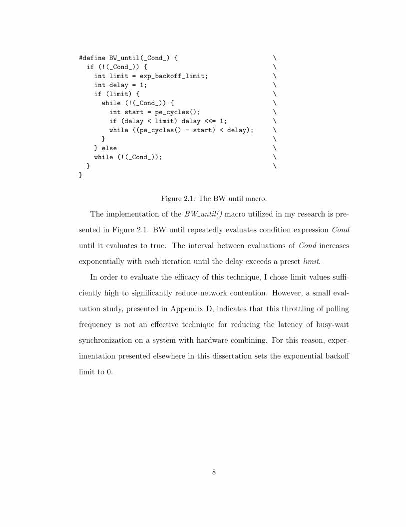
#define BW_until(_Cond_) { \if (!(_Cond_)) { \int limit = exp_backoff_limit; \int delay = 1; \if (limit) { \
while (!(_Cond_)) { \int start = pe_cycles(); \if (delay < limit) delay <<= 1; \while ((pe_cycles() - start) < delay); \
} \} else \while (!(_Cond_)); \
} \}
Figure 2.1: The BW until macro.
The implementation of the BW until() macro utilized in my research is pre-
sented in Figure 2.1. BW until repeatedly evaluates condition expression Cond
until it evaluates to true. The interval between evaluations of Cond increases
exponentially with each iteration until the delay exceeds a preset limit.
In order to evaluate the efficacy of this technique, I chose limit values suffi-
ciently high to significantly reduce network contention. However, a small eval-
uation study, presented in Appendix D, indicates that this throttling of polling
frequency is not an effective technique for reducing the latency of busy-wait
synchronization on a system with hardware combining. For this reason, exper-
imentation presented elsewhere in this dissertation sets the exponential backoff
limit to 0.
8
2.1.2 Distributed Approaches
An alternative approach for minimizing hot spot contention is the use of tech-
niques originally developed for message-passing systems. Each process awaiting
an event is allocated its own state variable that indicates when it may proceed.
Busy-wait polling is distributed among several memory locations that function
as message mailboxes. Since waiting is distributed, the rate of polling for each
these variables does not increase with system size. Serialization in the network
and memory modules (MMs) can be minimized on architectures with memory
bandwidth that scales with the number of processors when the references are
uniformly distributed throughout shared memory.
In [27], Mellor-Crummey and Scott present several distributed algorithms
that exploit various forms of processor-local shared memory to further reduce
the latency of and congestion caused by memory references generated by busy-
wait polling. Their technique is called local spin waiting.
Recall that each process executing a distributed coordination algorithm busy-
waits on a distinct coordination variable; A local-spin-waiting coordination algo-
rithm places these busy-wait variables in memory collocated with (local to) the
waiting processors. Therefore, memory references generated by busy-waiting do
not contend for the shared processor-to-memory interconnection since they are
satisfied by the collocated memory unit.
The distributed local-spin-waiting algorithms of Mellor-Crummey and Scott
are known by the initials of their originator: MCS. MCS algorithms are well
suited for both cache-coherent and NUMA architectures: No network traffic is
9
generated by polling traffic to control variables if their cache lines are not utilized
for other variables. Alternatively, on NUMA architectures that pair processors
with memory units, busy-wait variables can be co-resident with the processor
that polls them, thereby not generating congestion in the shared-memory inter-
connect.
MCS algorithms minimize memory congestion due to busy waiting at the cost
of increasing the number of shared memory operations that must occur when
centralized wake-up semantics are needed such as when a barrier is satisfied, or
a writer lock is released.
While they do not busy-wait on centralized control variables, distributed
busy-wait algorithms may nonetheless generate hot-spot accesses. For example,
MCS algorithms for readers and writers coordination also utilize a small number
of centralized state variables that are accessed by all processes requesting, enter-
ing, and releasing a lock. My research discovered that the serialized accesses to
these variables can result in substantial latency and poor performance for these
coordination algorithms.
2.2 Introduction to the Ultracomputer Architecture
Large-scale, shared-memory computation requires memory systems with band-
width that scales with the number of processors. Multi-stage interconnection
fabrics and interleaving of memory addresses among multiple memory units can
provide scalable memory bandwidth for memory reference patterns that are uni-
formly distributed throughout memory. However, the serialization of memory
10
transactions at each memory unit is problematic for memory reference patterns
whose mapping to memory units is unevenly distributed. The Ultracomputer
combining network [2] reduces this serialization when the unevenly distributed
access patterns are due to hot spot accesses.
I begin this section with an overview of the NYU Ultracomputer architecture
and its combining network, including a summary of the motivation for some
of the chosen design options. This overview is followed by an examination of
the network’s behavior when processors issue solely hot-spot references, which
approximates the pattern generated by busy-wait polling. An analytical model
is presented that generates values consistent with simulation results. Two ap-
proaches to improving memory latency for hot-spot polling are presented includ-
ing a novel adaptive design. The adaptive design has characteristics that fit the
analytical model, and simulation results are again consistent with the model.
2.2.1 Architectural Model
The NYU Ultra3 prototype incorporates a realization of the combining network
proposed in [2] to route memory transactions between processors and memory.
This UMA (uniform memory access) multi-processor computer appears to the
programmer as an approximation of an idealized CRCW1 PRAM2. Figure 2.2 is
an illustration of this model: several processing elements (PEs) are connected
to a single shared memory. The idealized PRAM model, which can only be
approximated in hardware, provides single cycle access from all processors to
1Concurrent Read, Concurrent Write2Parallel Random Access Model
11
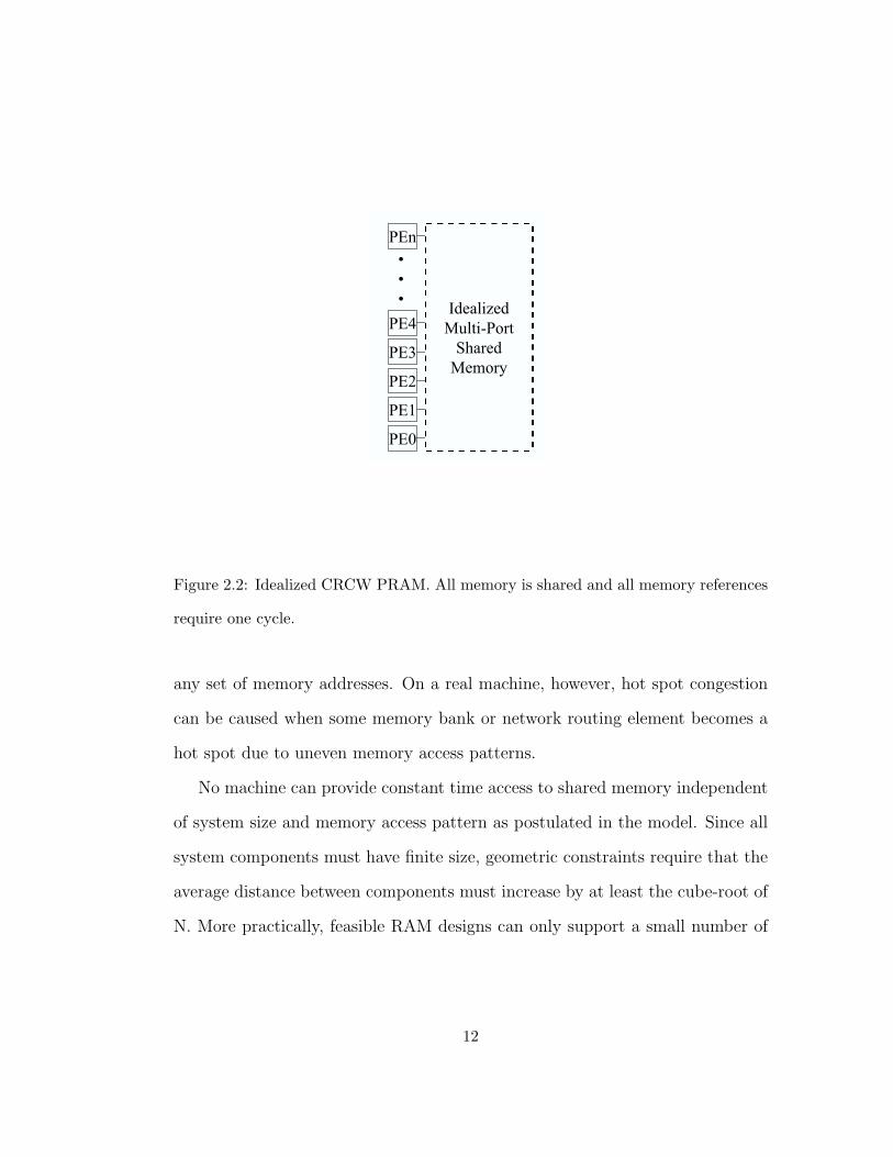
Figure 2.2: Idealized CRCW PRAM. All memory is shared and all memory references
require one cycle.
any set of memory addresses. On a real machine, however, hot spot congestion
can be caused when some memory bank or network routing element becomes a
hot spot due to uneven memory access patterns.
No machine can provide constant time access to shared memory independent
of system size and memory access pattern as postulated in the model. Since all
system components must have finite size, geometric constraints require that the
average distance between components must increase by at least the cube-root of
N. More practically, feasible RAM designs can only support a small number of
12
concurrent accesses. This limitation can be mitigated by interleaving memory
among multiple memory modules (MMs) and by providing an interconnection
fabric that concurrently routes independent transactions between processors and
memory.
Nonetheless, providing a high-bandwidth connection fabric between MMs
and PEs suitable for all memory reference patterns remains a challenge. All-
to-all connections (N2 links) are prohibitively expensive. A scalable solution
chosen for many commercial and research systems, including the NYU Ultra-
computer prototype, incorporates interleaved memory and a logarithmic depth
multistage interconnection network. This network distributes messages commu-
nicating memory accesses among a large number of system components that, in
concert, can efficiently transport them between processors and memory. These
designs provide memory bandwidth that scales with the number of processors
and impose a minimum memory latency that grows logarithmically with the
number of processors.
Many variants of this architecture have been implemented in commercial
and other research systems [44] [23] [17]. These designs are problematic if
some network and/or memory component is the target of a disproportionately
large fraction of memory references. The resulting contention at these hot com-
ponents can cause memory system bottlenecks, substantially reducing system
performance.
An important cause of non-uniform memory access patterns is hot-spot mem-
ory accesses generated by centralized busy-waiting coordination algorithms. The
Ultracomputer architecture includes network switches [37] with logic to reduce
13
this congestion by combining into a single request multiple memory transactions
(e.g. load, store, fetch-and-add) that reference the same memory address.
The Ultra3 architecture has the following characteristics that are desirable
for non-hot-spot traffic:
• Bandwidth linear in N, the number of PEs.
• Latency, i.e. memory access time, logarithmic in N.
• Only O(N log N) identical components.
• Routing decisions local to each switch; thus routing is not a serial bottleneck
and is efficient for short messages.
In [15], Gottlieb presents an overview of the Ultracomputer architecture.
This architecture can be scaled from uniprocessors to MIMD systems containing
thousands of processors. These systems are composed of three component types:
Processing Elements (PEs), Switches (SWs), and Memory Modules (MMs). The
upper half of Figure 2.3 illustrates a uniprocessor system composed of a single
MM and PE. All communication between processors and memory is via a split
transaction messaging interface that allows requests and responses to be routed
independently. The network routes messages rather than establishing end-to-
end-connections (as in the BBN Butterfly [44]). This allows multiple memory
transactions with overlapping lifetimes to use the same network connection at
different times.
The primary novel feature of the Ultracomputer architecture is the ability
to mitigate hot-spot congestion through combining. Combining occurs in the
14

routing switches (SW), which merge pairs of concurrent memory transactions
referencing the same address. The feasibility of this design was demonstrated
by constructing a sixteen processor Ultra3 prototype in which the switches were
full-custom CMOS devices. To support my research, I constructed USim, a
simulator of shared memory systems that can emulate Ultra3 systems of varying
sizes. USim also implements several variants of Ultra3 including a novel adaptive
combining design described in this thesis.
Ultra3 PEs contain an AMD 29050 [6] processor, direct-mapped instruction
and write-through data caches, and a split transaction “TowardMM” memory
interface that supports multiple outstanding requests. Like the SGI Origin 2000
system, several atomic fetch-and-phi operations are directly implemented by
the MM, which contain a corresponding “TowardPE” processor interface, RAM
and ALU. Memory consistency is managed via software control. Cacheability is
controlled on a per-page basis, however user-mode configuration registers permit
the processor-to-network interface (PNI) to enforce sequential consistency in
hardware by disallowing multiple outstanding references to shared read-write
memory
Recall that the Ultra3 implements a system of multiple independent proces-
sors with a single shared memory. The lower half of Figure 2.3 illustrates a
two-processor Ultracomputer. Two MMs are aggregated into a unified memory
with twice the storage of a single MM. Physical memory addresses are interleaved
between the two MMs: even addresses in MM0 and odd addresses in MM1. A
two-by-two routing switch (SW) routes forward path (requests to MM) messages
from either PE to the appropriate MM based on a single bit in the destination
15
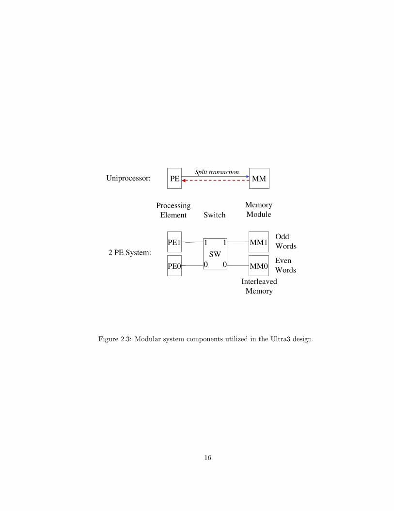
Figure 2.3: Modular system components utilized in the Ultra3 design.
16
address field. Similarly, reverse-path (response to PE) messages are routed back
to the PE specified in the response message. Return-path routing information
for the response generated by an MM is generated by the switch during forward
routing and inserted into the message.
This two-processor system’s memory bandwidth is potentially twice the band-
width of the uniprocessor since both memory modules can simultaneously accept
memory requests (provided that memory accesses are distributed evenly between
them). The switch design utilizes a variant of cut-through routing [29] that im-
poses a latency of one clock cycle when there is no contention for an outgoing net-
work link. When there is contention for an output port, messages are buffered on
queues associated with each output port. Investigations by Dickey [7], Liu [35],
and others indicate that these queues significantly increase network bandwidth
for large systems with uniformly distributed memory access patterns.
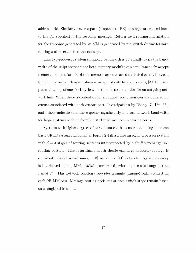
Systems with higher degrees of parallelism can be constructed using the same
basic Ultra3 system components. Figure 2.4 illustrates an eight-processor system
with d = 3 stages of routing switches interconnected by a shuffle-exchange [47]
routing pattern. This logarithmic depth shuffle-exchange network topology is
commonly known as an omega [33] or square [41] network. Again, memory
is interleaved among MMs: MMi stores words whose address is congruent to
i mod 2d. This network topology provides a single (unique) path connecting
each PE-MM pair. Message routing decisions at each switch stage remain based
on a single address bit.
17
Figure 2.4: 8-Processor Ultracomputer
18
Latency Issues and Introduction to Combining
To prevent the processor-to-memory network from becoming a bottleneck for
machines comprising large numbers of PEs, an important design goal for the
NYU Ultracomputer was bandwidth proportional to the number of PEs. In
addition to combining, several well known design idioms were employed:
• The network is pipelined, i.e. the delay between messages equals the switch
cycle time not the network transit time. (Since the latter grows logarith-
mically, non-pipelined networks can have bandwidth at most O(N/log N).)
• The network is message switched, i.e. the switch settings are not main-
tained while a reply is awaited. (The alternative, circuit switching, is in-
compatible with pipelining [15].)
• A queue is associated with each switch to enable concurrent processing of
requests for the same port. (The alternative adopted by Burroughs [4] of
killing one of the two conflicting requests also limits bandwidth to O(N/log
N), see Kruskal and Snir [32].
Each word-sized (32 bit) reference to a shared variable on an Ultra3 results in
the generation of a two-packet forward-path (toward-MM) message. The network
can accept one packet each cycle, and therefore, in the absence of contention, can
accept one such message every two cycles. The first packet of a message contains
the target address and opcode, which is sufficient information for routing and
combining decisions.
19
An MM can accept only one message every four cycles. A two packet reverse-
path (toward-PE) response message is emitted by the MM two cycles after the
first packet of a forward-path message is accepted. In the simulated polling
experiments described below, a PE emits a new memory request message six
cycles following the arrival of the first packet of a response message for the
previous request.
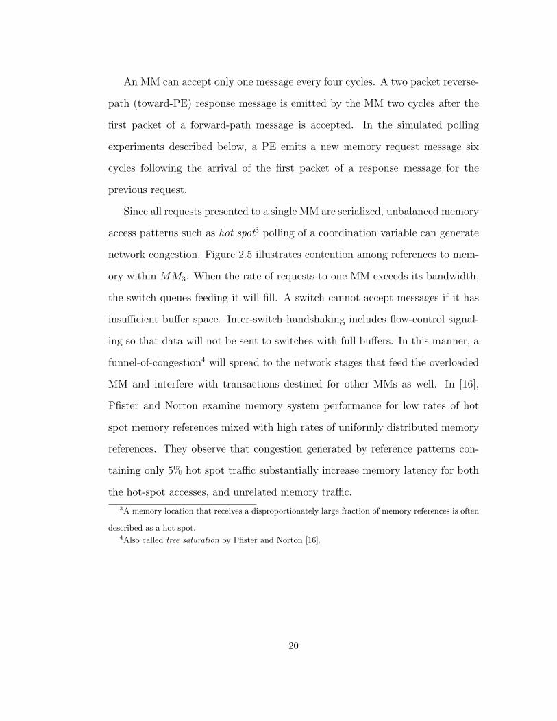
Since all requests presented to a single MM are serialized, unbalanced memory
access patterns such as hot spot3 polling of a coordination variable can generate
network congestion. Figure 2.5 illustrates contention among references to mem-
ory within MM3. When the rate of requests to one MM exceeds its bandwidth,
the switch queues feeding it will fill. A switch cannot accept messages if it has
insufficient buffer space. Inter-switch handshaking includes flow-control signal-
ing so that data will not be sent to switches with full buffers. In this manner, a
funnel-of-congestion4 will spread to the network stages that feed the overloaded
MM and interfere with transactions destined for other MMs as well. In [16],
Pfister and Norton examine memory system performance for low rates of hot
spot memory references mixed with high rates of uniformly distributed memory
references. They observe that congestion generated by reference patterns con-
taining only 5% hot spot traffic substantially increase memory latency for both
the hot-spot accesses, and unrelated memory traffic.
3A memory location that receives a disproportionately large fraction of memory references is often
described as a hot spot.4Also called tree saturation by Pfister and Norton [16].
20
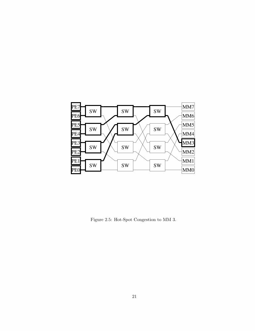
Figure 2.5: Hot-Spot Congestion to MM 3.
21
A common cause for non-uniform memory traffic is hot-spot access patterns
generated by busy-waiting coordination algorithms. These algorithms generate a
large number of requests to a small number of variables. Ultra3 switches contain
logic to reduce the MM and network congestion generated by these access pattern
by combining pairs of forward-path (memory request) messages that access the
same memory address and only issuing a single request to the next network stage
or MM. Response messages generated by combined messages are de-combined at
the switch where the combining occurred into a pair of return-path (response)
messages that are routed to the requesting PEs. This technique potentially
reduces contention for the MM containing the hot-spot variable by a factor of
two at each network stage where combining occurs.
Combining of Fetch-and-add
Recall that fetch-and-add, normally coded as FAA(variable, addend), is an mem-
ory transaction atomically implementing the following function:
FAA(int *var, int addend) // atomic fetch-and-add
{
temp = *var;
*var = *var + addend;
return temp;
}
Since fetch-and-add is utilized as a centralized coordination primitive, con-
current fetch-and-add operations will often be directed at the same location.
22
Thus, as indicated above, it is crucial in a design supporting large numbers of
processors not to serialize this activity.
Common implementations of atomic fetch-and-φ transactions compute the
atomic operation φ in the PE that issues the request. On multi-processor sys-
tems, some form of coordination mechanism must be employed to guarantee
atomicity for the entire read-modify-write operation One approach includes a
hardware locking mechanism that effectively embeds all memory references in-
cluding these special ready-modify-write operations within mutually exclusive
critical sections. Another approach uses conditional operations such as compare-
and-swap[5] or load-linked/store-conditional[21] that are used to abort transac-
tions if the shared control variable is modified by another process. Both of these
approaches impose serialization bottlenecks with a per-transaction latency of
least two memory accesses.
The inclusion of adders in MMs to directly support fetch-and-add reduces
the bottleneck to the memory transactions themselves. For these systems, a
PE’s execution of FAA(X, a), consists of generating a message M containing
an opcode (add), operand (addend), and address (of X). When M reaches the
MM containing X, the value of X and the operand a are brought to the MM’s
adder, the sum is stored in X, and the old value of X is returned in a response
message through the network to the requesting PE. The importance of atomic
fetch-and-φ operations (such as fetch-and-add) for synchronization led to the
incorporation of the Ultracomputer architecture’s ALU-in-memory design in the
SGI Origin 2000 system [23].
23
Enhanced switches permit the network to combine concurrent memory op-
erations, including several fetch-and-φ operations (notably including fetch-and-
add). When two fetch-and-add operations referencing the same shared variable,
say FAA(X, e) and FAA(X, f), meet at switch S, S forms the sum e + f and
transmits the combined request FAA(X,e+f). In order to permit the decom-
bining of response messages (which is described below), the value of e and the
opcode add are stored in a local memory of S called the wait buffer (see Figure
2.6).
Upon receiving FAA(X, e+f), the MM updates X to X+e+f and generates
a response message containing T , the value of X before the update. When T
arrives at switch S, S transmits T to satisfy the original request r1 = FAA(X, e)
and transmits T + e to satisfy the original request r2 = FAA(x, f). Note that
this result is consistent with the serialization of r1 followed by r2.
Messages can combine at multiple stages. Figure 2.7 illustrates perfect com-
bining of four fetch-and-add transactions with addends 1,2,4, and 8 into a single
transaction with addend 15. Each switch is annotated with the value stored
within its wait buffer, and the stored return-path routing information associated
with the original request r2.
The preceding description assumed that the requests to be combined arrive at
a switch simultaneously. The Ultra3 switch design exploits a characteristic of the
systolic folded FIFO queue of Guibas and Liang [34] to compare messages that
are already enqueued. This folded queue is constructed from a series of slices,
each containing storage for two packets. In this queue design, each concurrently
enqueued pair of messages are, at some time, stored within the same queue slice.
24
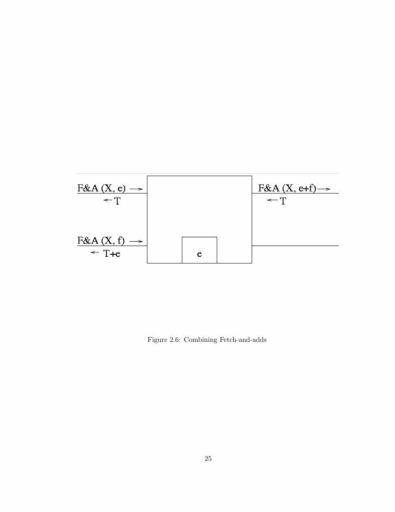
Figure 2.6: Combining Fetch-and-adds
25
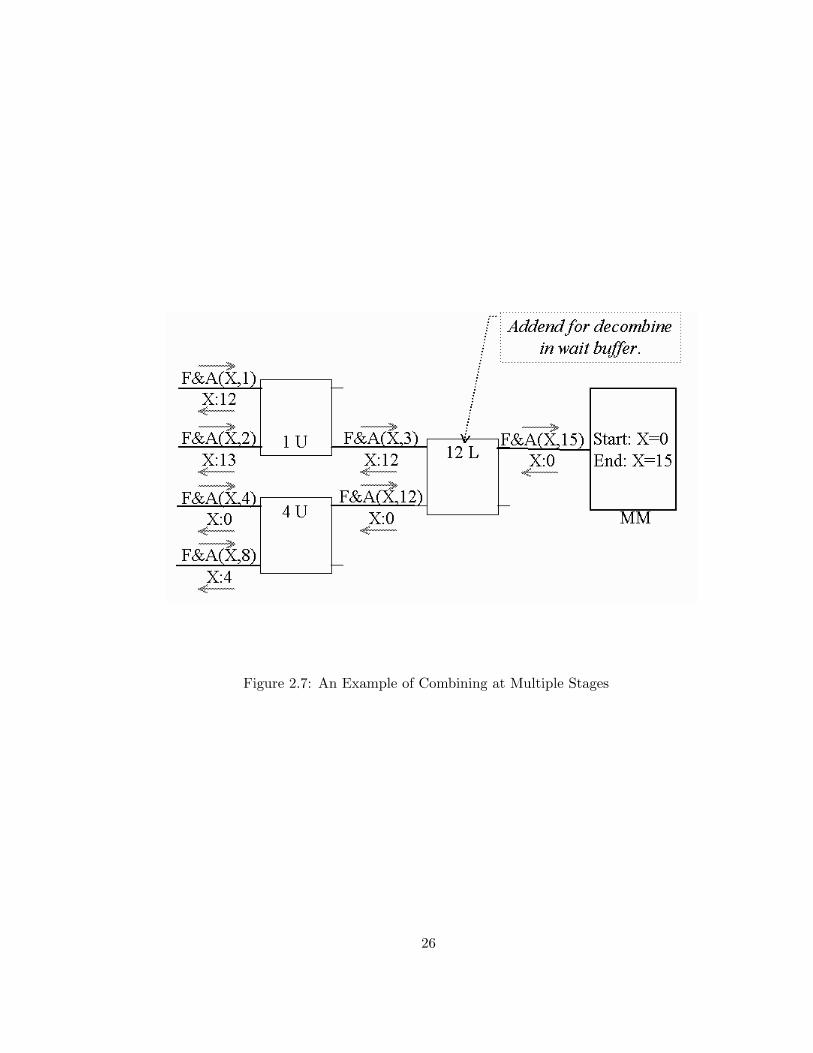
Figure 2.7: An Example of Combining at Multiple Stages
26
The Ultra3 combining switches exploit this property by inserting a comparator
to detect messages representing combinable fetch-and-φ transactions within each
slice.
In order to permit combining of concurrent memory loads and fetch-and-add
transactions, the Ultra3 prototype issues load operations as fetch-and-add oper-
ations with zero addends. Store operations are similarly converted to fetch-and-
store operations (a combinable atomic swap) whose return values are ignored.
Multiple concurrent stores can therefore be combined, providing results equiva-
lent to a consecutive serialization, where the value stored by all but one of the
transactions is discarded.
The omega network topology provides only a single path connecting each
PE-MM pair and therefore a transaction’s forward and return path messages
must visit the same switches in opposite order. This is well suited for combin-
ing networks since messages must be de-combined in the opposite order that
they combined. Combining is compatible with network topologies with mul-
tiple routes between memories and processors (such as hypercubes) providing
responses to combined messages are explicitly routed to the switches where they
combined.
2.2.2 Ultra3 Combining Switch Design
Memory latency due to message communication is proportional to switch cycle
times and grows with queuing delays. A combining switch design was chosen for
Ultra3 that reduces cycle time at the cost of restricting the cases where messages
will combine.
27
Simulation studies conducted at the time the Ultra3 design was chosen demon-
strated that network congestion generated by low rates of hotspot traffic inserted
into uniform access patterns only slightly increased the latency of the uniform
accesses[7][35]. However, these experiments did not examine the latency of the
hotspot memory references.
In contrast, my simulation studies investigate the latency of the 100% hot
spot loads generated by the busy-wait polling typical of centralized coordination
algorithms. Like the “closed queuing” loads5 investigated by Lee Kruskal and
Kuck [14], exactly one hot spot memory reference is continuously outstanding
from each PE engaging in busy-wait polling. As was observed by Lee. et al.,
the latency of these hot spot accesses is significantly higher than for uniformly
distributed loads at the same rate.
Below, I provide an overview of the Ultra3 switch design to a sufficient level
of detail to understand the motivations for the switch design chosen for the
Ultra3 prototype. A detailed description of the switch design appears in [7]. In
Chapter 5, I describe how this design has high latency for hot spot reference
patterns and present a model that accurately predicts memory reference latency
for systems where all processors continuously poll the same hot spot variable. In
addition, Chapter 5 presents a novel technique called adaptive combining that
has substantially lower latency for memory references due to hot spot polling.
The Ultra3 switch design has the following characteristics:
• Distinct data paths do not interfere with each other. That is: (1) a new
message can be accepted at each input port provided queues are not full,5A queuing model where the total number of messages in the system is constant is called closed.
28
and (2) a message destined to leave at some output port will not be pre-
vented from doing so by a message routed to a different output port.
• A first packet of a message entering a switch with empty queues when
no other entering message is destined for the same output port leaves the
switch at the next cycle. The capability to combine memory requests is
implemented within switch queues in a manner that does not delay the
transmission of messages.
• Flow control information is computed and transmitted in parallel with mes-
sages.
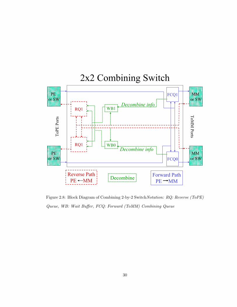
Figure 2.8 illustrates an Ultra3 two-by-two switch including the logic required
to support combining. A multi-input queue is associated with each of the four
output ports. These queues are named to reflect the direction of the messages
they contain. The queues for forward-path TowardMM messages are augmented
with logic to combine requests. These forward path combining queues (FCQ) also
emit information required to de-combine MM response messages to an associative
memory called a wait buffer (WB). A wait buffer compares response FromMM
messages with de-combine information stored in its associative memory. A match
indicates that an additional de-combine message must be generated and inserted
onto a return-path queue (RQ) for transmission toward a PE.
To describe the process whereby requests are combined in a switch, we view
a request as consisting of several components: a function indicator6 φ, a target
6For example, a forward path message representing a fetch-and-add’s function indicator will be the
opcode representing add.
29
Reverse PathPE MM
2x2 Combining Switch
ToPE
Ports
ToMM
Ports
PE or SW
PEor SW
MM or SW
MM or SW
RQ1
RQ1
FCQ1
FCQ0
Forward PathPE MM
Decombine info
Decombine info
WB1
WB0
Decombine
Figure 2.8: Block Diagram of Combining 2-by-2 SwitchNotation: RQ: Reverse (ToPE)
Queue, WB: Wait Buffer, FCQ: Forward (ToMM) Combining Queue
30
memory address, and data.
As a request Rnew in a ToMM combining queue Q progresses toward the
queue head, Rnew is compared against all requests previously enqueued but not
yet combined or transmitted from Q using as key the function indicator and
referenced memory address from Rnew (the ToMM queue structure is described
below). If no request matches Rnew, then no combining is possible and Rnew will
transmitted to the next stage (or an MM if Q is in the network stage nearest to
memory) after it becomes the head item.
Otherwise, let Rold denote the earliest enqueued message in the ToMM queue
that matches Rnew. Then, to combine the requests in a manner giving the same
results as the serialization Rold followed immediately by Rnew, Rnew is deleted
from Q and the queue element containing Rold is annotated as being combined
with Rnew. At the time Rnew is deleted from Q:
1. The operand, function indicator, and return-path (TowardPE) addressing
fields of Rold and the return-path addressing fields of Rnew are transmitted
to the Wait Buffer to await a response message from memory.
2. A combined message Rcomb is emitted. If the function indicator specifies a
fetch-and-store operation, then Rold, Rnew, and Rcomb all represent fetch-
and-store operations and the operand of Rcomb is the operand of Rnew.
Alternatively, if the function indicator specifies a fetch-and-add operation
(indicating that Rold, Rnew, and Rcomb represent fetch-and-add operations),
then the operand of Rcomb is the sum of the operands of Rold and Rnew.
Other field of Rcomb contain the same values as the corresponding fields of
31
Rold.
Thus, for each pair of combined Rold and Rnew, a single combined message
is emitted to the next stage and a wait buffer entry stores their opcode, the
operand of Rold, and return-path addressing information required to construct
both return-path messages as follows.
After arriving at a FromMM port, a returning request, Rret, is both routed to
the appropriate ToPE queue and used to associatively search the relevant wait
buffer. If a match occurs, a second de-combined message Rdecomb is generated
with the return-path addressing fields of Rnew. If the operations of the original
requests was fetch-and-store, then the datum returned in Rdecomb is the original
operand of Rold; If the operator is fetch-and-add, then the datum is the sum of
the datum of Rret and the operand of Rold.
To summarize the necessary hardware, we note that in addition to adders,
registers, and routing logic, each switch requires two instances of each of the
following three components.
Forward path (ToMM) queue: Entries are inserted and deleted in a queue-like
fashion, and matching entries may be combined. The ToMM queue also
incorporates an ALU to generate the content of combined messages, and a
wait-buffer port which emits information required to identify responses to
combined messages and compute their de-combined value.
Reverse path (ToPE) queue: Entries are inserted and deleted in a queue-like
fashion.
Wait Buffer: Entries may be inserted and associative searches are performed
32

with matched entries removed. A Wait-buffer also incorporates an ALU to
compute the contents of de-combined messages.
When Combining Can Occur
For combining to occur, multiple compatible (combinable) messages must be con-
currently enqueued within a switch. Minimization of cycle time was the primary
design objective for the two-by-two NYU combining switch. The minimization
of switch cycle time resulted in a design that we shall see requires a large number
of messages to be concurrently enqueued for high rates of combining to occur.
Memory latency due to message communication is proportional to switch
cycle times. Inter-switch communication and the computation required to im-
plement combining are the time-limiting components of the NYU switch. A
natural design for a combining queue includes an ALU between the queue head
and the network that computes combined operand values. This coupled ALU
design requires that the cycle time be at least the sum of ALU computational
and inter-switch communication latencies. The Ultra3 combining queue decou-
ples inter-switch communication and message combining by inserting the ALU
between the two head elements of forward path (toward-MM) queues. Since the
ALU executes on the packet immediately following the one being transmitted,
clock frequency is instead limited by the maximum (rather than sum) of the
computational and communication latencies. This increase in switch clock fre-
quency comes at a cost: a messsage at the queue head is ineligible for combining
since it cannot be routed through the ALU. Hence, a queue with a decoupled
ALU must contain at least three messages for combining to occur. In some of
33

the charts in this thesis, combining queues with coupled ALUs are abbreviated
“cfirst” since they permit combining to occur on the first queue slice.
Ultra3’s dual input forward-path combining queues are constructed from two
independent single-input forward-path combining queues (FCQs) whose outputs
are multiplexed. This design allows a switch S to simultaniously accept forward-
path messages from both input ports that must leave via the same forward-path
output port. Recall that that combining cannot occur in FCQs that contain
less than three uncombined messages. This dual-queue design, dubbed type B in
Dickey [7] thereby doubles (to six) the number of enqueued messages required
to achieve 100% combining to six. An alternative dual-input design (described
as “type A” by Dickey) reduces this minimum capacity to four.
Flow Control
All Ultra3 communication channels include flow-control signalling that prevents
the transmission of data to components with insufficent buffer space. Data is
transmitted to wait buffers at the same time a “combined” forward-path mes-
sage is transmitted to the successive stage. Therefore, the maximum number of
concurrently outstanding forward-path (toward-MM) combined messages that a
switch will emit is therefore limited by:
• Wait buffer capacity,.
• the capacity of queues in successive (downstream) stages, and
• The number of concurrently outstanding combinable memory transactions
issued by upstream processors.
34
Chapter 3
Summary of Experimental
Objectives and Methodology
In the absence of contention, each processes executing the centralized bottleneck-
free coordination algorithms investigated by my research generates a constant
number of shared memory references and would therefore require constant ex-
ecution time on idealized Concurrent-Read Concurrent-Write (CRCW) Parallel
Random Access Machine (PRAM) [11] systems, in which each memory reference
requires a single cycle, independent of memory access pattern. Unfortunately,
this idealized model, is unrealizable. Interleaved memory and multi-stage inter-
connection networks provide a reasonable approximation of a PRAM, provided
that memory reference patterns are uniformly distributed. However, memory
reference patterns typical of centralized busy-waiting generate hot spot traffic to
a small number of memory locations, resulting in hardware bottlenecks.
The Ultra3 switch design implements hardware combining as an improved
35
PRAM approximation for hot spot memory reference patterns. Several bottleneck-
free algorithms for busy-waiting coordination that exploit these improved char-
acteristics were developed by others (e.g. [2], [45], [10],[50]).
My contributions include the discovery of several new bottleneck-free algo-
rithms for iner-process coordination that generate fewere memory references than
those previously known. These algoirthms are bottleneck-free only on systems
that combine feetch-and-add operations, including those with non-unit addends.
I also discovered bottleneck-free coordination algorithms that require only the
restricted forms of fetch-and-add with unit addends often called “fetch-and-
increment” and “fetch-and-decrement”[12].
John Mellor-Crummen and Michael Scott at the University of Rochester de-
veloped extremely efficient algorithms that enforce inter-process coordination[27],
[38]. These algorithms minimize hot spot memory reference patterns and there-
fore are well suited for the large number of systems that do not implement
combining.
The primary goal of my experimental research it to compare, over a range of
system sizes, the performance of centralized bottlenck-free algorithms executed
on systems that implement hardware combining with distributed algorithms that
minimize hot spot reference patterns on similar systems that do not implement
hardware combining.
My experimental approach utilizes micro-benchmarks that measure the la-
tency of coordination using both approaches to inter-process coordination. This
research also quantifies the relative performance of several centralized bottleneck-
free algorithms.
36
The only system implementing hardware combining is the sixteen processor
NYU Ultra3 prototype. However it is poorly suited for these experiments:
• With only sixteen processors, it is too small to conduct interesting scala-
bility studies of these two approaches to interprocess coordination.
• Ultra3 does not implement direct processor-to-memory connections 1 com-
mon in NUMA systems that are exploited by the local-spin algorithms of
Mellor-Crummey and Scott.
• The Ultra3 design provides mechanisms to instrument system behavior;
however, these features were never implemented.
I constructed a simulator named USim that closely approximates the timing
of programs executing on Ultra3. USim exposes many architectural parameters
including system size, availability of combining, and NUMA memory connec-
tions. Appendix B contains a description of USim including a complete enumer-
ation of the USim configuration parameters used in my research. This appendix
also describes a validation study that compares the behavior of USim with the
sixteen processor Ultra3 prototype.
3.1 General Methodology
While performing the research described in subsequent chapters of this disser-
tation, I conducted two classes of experimentation. The first class of experi-1It is common to co-locate memory units with processors; these designs include a direct link between
these co-resident pairs that has higher performance than communication with memory co-resident with
a different processor.
37
mentation, which I refer to as algorithmic, measures the performance of several
algorithms for inter-process coordination to determine the relative performance
of the various algorithms.
The second class of experiment, which I refer to as architectural, investigates
the behavior of the memory systems of these machines when programs generate
synthetic memory loads with properties that are easy to analyze.
These experiment classes are interrelated. The next chapter describes experi-
ments that compare the performance of centralized algorithms to enforce barrier
coordination with the performance of distributed local-spin algorithms of Mellor-
Crummey and Scott. These algorithmic experiments, which measure the number
of processor cycles required to execute a synchronization algorithm, indicate that
the centralized bottleneck-free barriers have substantially greater latency than
expected by the Ultra3 design team. The following chapter describes architec-
tural experiments indicating that this high latency is due to correspondingly
higher-than-expected latency for hot spot memory references.
I also present variations of the combining switch design that are evaluated
by additional rounds of architectural experiments. These experiments indicate
that several alternative designs enjoy substantially lower memory latency for the
problematic hot spot memory reference patterns.
Algorithmic experiments using these alternative switch designs are presented,
demonstrating that the latency of centralized coordination is reduced by the
improved architectures. Nonetheless, bottleneck-free, distributed algorithms for
inter-process coordination outperfrom centralized busy-waiting even with the
improved architectures. However, the only such distributed algorithms known
38
to me are for the highly structured barrier problem required for BSP super-step
coordination. My algoirthmic experiments also indicate that, in the absence of
contention, my bottleneck-free algorithms for other coordination problems have
lower latency than the competing algorithms I studied.
3.2 Relevance of the 1995 Ultra3 Design in 2002
The Ultra3 design was essentially frozen around 1990 and the prototype com-
pleted around 1995. Ultra3 is fully synchronous, driven by a single 10MHz clock.
Current circuit designs permit systems to be constructed more than two orders
of magnitude faster than Ultra3. In addition, the AMD29050 utilized as the
Ultra3 CPU only permits in-order execution of instructions, whereas current mi-
croprocessors are capable of out-of-order execution. Nonetheless, I argue that
neither of these significant architectural advances diminishes the relevance of the
research presented herein.
The relative timing of significant components has remained approximately
equal over the intervening years. Processors, network switches, and communica-
tion links continue to be constructed using the same fabrication techniques and
therefore are capable of signaling at proportionally higher rates.
In contrast, access latency to the core of a DRAM has remained essentially
constant over this ten year period. However, cache-in-DRAM techniques can
increase DRAM access rates for frequently accessed locations (such as hot spots)
to match those of other system components. The section of this dissertation that
investigates the properties of hot spot polling on combining networks evaluates
39
the impact of memory systems of varying speeds relative to other components.
Modern processors are capable of masking memory latency by issuing mul-
tiple concurrently outstanding memory references, and masking functional unit
latency by reordering instructions, resulting in substantial speedups for many
programs. Each Ultra3 PE contains an AMD29050 processor, which can is-
sue only a small number of concurrently outstanding memory references, and
does not reorder instructions. However I do not expect this significant architec-
tural difference to significantly change coordination latency since both of these
execution optimizations are incompatible with the strict sequential consistency
required for the correct execution of synchronization algorithms.
In order to ensure the correct execution of coordination algorithms, processors
capable of these optimizations provide mechanisms to force memory references
to be issued in a strictly specified order without overlap. In the important case
of coordination algorithms, this sequence will be equivalent the order in which
they appear in the source code. Therefore, the sequence of memory references
generated by any processor and their potential overlap will not change due to
these architectural optimizations. Since memory latency dominates the execu-
tion time of these coordination algorithms, synchronization latency will not be
significantly changed if the Ultra3 PEs are enhanced with more modern proces-
sors.
40

Chapter 4
Performance Evaluation of
Centralized and Distributed
Barriers
Only the NYU Ultra3 prototype does not serialize atomic fetch-and-φ memory
operations referencing the same variable. This serialization, present in other
shared-memory systems, causes execution bottlenecks that limit the scalability
of centralized busy-wait coordination algorithms. In response to this limitation,
several coordination algorithms that avoid or minimize hot spot reference pat-
terns were developed. Instead of utilizing a small number of shared coordination
variables for hot spot polling, these hot spot-free algorithms distribute busy-wait
polling to multiple variables in distinct MMs.
In this chapter, I compare the performance of a centralized algorithm with a
distributed algorithm on simulated Ultra3 systems of varying sizes. My objective
41

is to evaluate distributed and centralized algorithms developed independently
of my contributions. The algorithms selected are generally recognized as best-
of-breed: The bottleneck-free, centralized fetch-and-add based barrier algorithm
of Dimitrovsky [9] that predates my algorithmic contributions was used in the
Ultracomputer’s runtime libraries. The local-spin, distributed algorithm was first
proposed by Hensgen, Finkel,and Manber in [20] and adapted for local spinning
by Mellor-Crummey and Scott [27]. In experimental results, this algorithm is
identified as the MCS dissemination barrier and is evaluated on a simulated
NUMA system with characteristics similar to the NYU Ultra3.
4.1 Introduction to Barrier Coordination
Barrier coordination algorithms are useful for enforcing explicit coarse-grained
synchronization among a group of cooperating asynchronous processors. A com-
mon use of these algorithms is in the implementation of run-time environments
for bulk synchronous programs (BSP) [49]. BSPs are partitioned into a sequence
of super-steps such that all processes must complete super-step n before they
begin super-step n+1.
In order to enforce coarse-grain synchronization, coordination code needs
to be inserted at the transition between super-steps. Algorithms that enforce
this coarse synchrony are are called barriers: each process executing a barrier
algorithm may not proceed until all participating processes also begin executing
the barrier algorithm. Once all participating processes commence execution
of the barrier algorithm, the barrier is said be satisfied and all participating
42
processes may leave the barrier and commence their next superstep. Barrier
algorithms are typically implemented as a subroutine: a call to barrier() does
not return in any participating process until all such processes have called it.
4.2 Dimitrovsky’s Centralized Fetch-and-add Barrier
Dimitrovsky’s barrier algorithm utilizes a single shared counter variable c that is
read and modified using combinable atomic fetch-and-add operations. Processes
that complete superstep i + 1 increment c, and then busy-wait on c’s value to
determine when to commence superstep i + 1. An important attribute of this
algorithm is that, on an idealized PRAM, no processor will issue more than four
shared accesses in the interval between the last processor’s completion of the ith
superstep and all processor’s commencement of the i + 1th superstep.
Unfortunately the idealized PRAM model can only be approximated. Clearly,
if combining is not available and all references to c must be serialized, each
processor’s increment and subsequent polling of c will become a serial bottleneck.
The Ultracomputer’s combining network parallelizes accesses to c and therefore
was expected to eliminate this bottleneck.
4.3 High-Performance Distributed Barriers for Shared
Memory Systems
In [27], John Mellor-Crummey and Michael Scott extend the technique of dis-
tributing hot spots throughout memory to exploit PE-MM pairings in NUMA
43

architectures. An important property of the MCS algorithms is that each shared
variable v that is the target of busy-waiting is associated with a particular PE π.
No PE other than π will poll v. Note that references between PEs and their local
MMs are local accesses and do not need to cross the interconnection network.
Therefore, polling by the MCS algorithms is not a source of congestion in the
processor-to-memory interconnection network.
Three MCS algorithms for barrier coordination are presented in [27]. These
algorithms, named Tournament, Tree, and Dissemination, exploit processor-local
shared memory to minimize memory congestion caused by hot-spot accesses.
These algorithms do not generate hot-spot accesses and therefore do not benefit
from combining. As local-spin algorithms, all their inter-process communication
is implemented as writes to shared memory. Note that communication latency
is reduced to one network traversal since the receiving processor is co-resident
with the referenced MM.
In order to compare the performance of centralized barriers that utilize com-
bining fetch-and-add with barrier algorithms that do not exploit hardware com-
bining, this dissertation includes a performance evaluation of the MCS dissemi-
nation barrier algorithm. This algorithm is widely used in shared-memory MIMD
systems and is identified by Mellor-Crummey and Scott as having lower super-
step latency than the MCS tournament and tree algorithms.
Pseudo-code for dissemination barrier including algorithms to initialize its
data structures appears in Figure 4.1. The procedure disseminationBarrier
is the barrier algorithm. Initialization requires two steps. First, one process
executes disseminationAlloc(), which allocates a vector of flags local to each
44
processor. After memory is allocated, DisseminationInit() is executed by each
processor. DisseminationInit, initializes a processor-local vector of pointers to
other processors’ flags that will be referenced by disseminationBarrier().
Recall that in a system of N participants in barrier coordination, each par-
ticipant must not begin superstep i + 1 until all N − 1 other participants have
completed superstep i. Each of the N participants in a dissemination barrier
successively synchronizes, in n = dlog2(N)e rounds, with a representative of suc-
cessively larger sets of participants, all of whom have completed the previous
superstep.
In the first round, each participant synchronizes with a representative r of
a singleton set containing only r itself. Subsequent synchronizations are with
representatives of other sets whose size recursively doubles with each round, so
that after n rounds, each participant has synchronized with representatives of
sets whose aggregate size (including potential repetitions) is 2n − 1.
The membership of each set that any participant synchronizes with is disjoint
if N is a power of two. Otherwise the last round of synchronization (with a rep-
resentative of a set of size 2n−1) will be with a representative of a set containing
2n − N participants represented in previous rounds. Therefore, after n rounds,
each participant will have synchronized with representatives of all N − 1 other
participants, thus determining that the barrier is satisfied.
45

const int numPes ; // #pa r t i c i p a n t sconst int logNumPes ; // c e i l ( l o g2 (numPes ))SHARED int ∗ I nd i c a t o r s [ numPes ] ; // f o r rendezvousPRIVATE int superStep = 0 ; // p r i v a t e to each PEPRIVATE int ∗ myIndicators ; // s e t by o ther PEsPRIVATE int ∗ i n f o rme rL i s t [ logNumPes ] ; // I s e t t h e s e i n d i c a t o r sPRIVATE int peId = getPeId ( ) ; // d i s t i n c t in range [ 0 . .N)
// run once , a l l o c a t e s f l a g v ec t o r l o c a l to each p a r t i c i p an td i s s em ina t i onA l l o c ( ) {
for ( int i = 0 ; i < numPes ; i++)Ind i c a t o r s [ i ] = callocPeLocalMem (pe , logNumPes , s izeof ( int ) ) ;
}
// compute ∗ f l a g s o f in formers to no t i f y , s t o r e in myIndicators// run once by each p a r t i c i p an t p r i o r to f i r s t supe r s t epd i s s em ina t i on I n i t {
myIndicators = Ind i c a t o r s [ peId ] ;for ( int i = 0 ; i < logNumPes ; i ++) {
int in former = ( peId + (1 << i ) ) % numPes ;i n f o rme rL i s t [ i ] = & Ind i c a t o r s [ in former ] [ i ] ;
}}
// run at each super s t ep by each p a r t i c i p an td i s s em ina t i onBar r i e r ( ){
superStep++;for ( int i = 0 ; i < logNumPes ; i ++) { // i = round index
i n f o rme rL i s t [ i ] = superStep ; // no t i f ybw unt i l ( myIndicators [ i ] == superStep ) ; // await
}}
Figure 4.1: MCS Dissemination Barrier
46
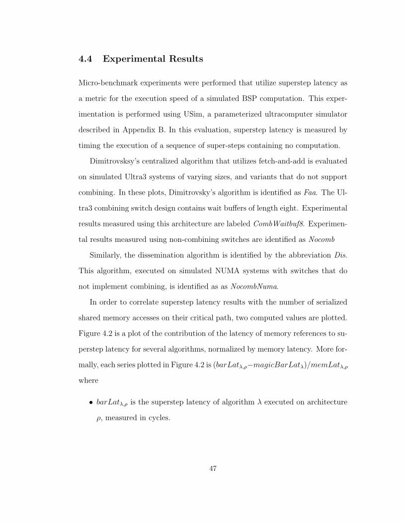
4.4 Experimental Results
Micro-benchmark experiments were performed that utilize superstep latency as
a metric for the execution speed of a simulated BSP computation. This exper-
imentation is performed using USim, a parameterized ultracomputer simulator
described in Appendix B. In this evaluation, superstep latency is measured by
timing the execution of a sequence of super-steps containing no computation.
Dimitrovsksy’s centralized algorithm that utilizes fetch-and-add is evaluated
on simulated Ultra3 systems of varying sizes, and variants that do not support
combining. In these plots, Dimitrovsky’s algorithm is identified as Faa. The Ul-
tra3 combining switch design contains wait buffers of length eight. Experimental
results measured using this architecture are labeled CombWaitbuf8. Experimen-
tal results measured using non-combining switches are identified as Nocomb
Similarly, the dissemination algorithm is identified by the abbreviation Dis.
This algorithm, executed on simulated NUMA systems with switches that do
not implement combining, is identified as as NocombNuma.
In order to correlate superstep latency results with the number of serialized
shared memory accesses on their critical path, two computed values are plotted.
Figure 4.2 is a plot of the contribution of the latency of memory references to su-
perstep latency for several algorithms, normalized by memory latency. More for-
mally, each series plotted in Figure 4.2 is (barLatλ,ρ−magicBarLatλ)/memLatλ,ρ
where
• barLatλ,ρ is the superstep latency of algorithm λ executed on architecture
ρ, measured in cycles.
47

• magicBarLatλ. is the superstep latency of algorithm λ executed on a
simulated idealized CRCW PRAM with single-cycle memory latency, and
• memoryLatλ,ρ. is the mean memory access latency, measured during the
execution of λ on ρ.
USim computes the mean hot spot latency every 1000 cycle epoch of execu-
tion. To ensure stability, measured values are collected only after the average
hot spot memory latencies measured in several successive epochs differ by less
than 10%.
Note that for the decentralized algorithms, which utilize local spinning, the
results of shared memory writes are immediately available to a local busy-waiting
processor upon arrival of the write at the target MM. For this reason, return-path
memory latency does not contribute to communication time. These algorithms
generate negligible network congestion, and forward path latency is approxi-
mately one half of contention-free round trip latency.
In the absence of contention, the latency of shared memory accesses on a
four-stage (16 PE) system is approximately twelve cycles, and two PEs engaging
in busy-wait polling can only generate negligible memory congestion. On these
systems, execution time of instructions that do not reference shared variables
can contribute substantially to superstep latency. In contrast, larger systems
generate correspondingly higher rates of hot spot accesses, and therefore sub-
stantially greater memory latencies relative to processor execution speed. This
is consistent with results presented in Figure 4.2 indicating that instructions not
referencing shared variables contribute significantly to superstep latency only on
48
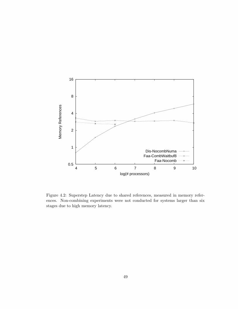
0.5
1
2
4
8
16
4 5 6 7 8 9 10
Mem
ory
Ref
eren
ces
log(# processors)
Dis-NocombNumaFaa-CombWaitbuf8
Faa-Nocomb
Figure 4.2: Superstep Latency due to shared references, measured in memory refer-ences. Non-combining experiments were not conducted for systems larger than sixstages due to high memory latency.
49
smaller systems.
Figure 4.3 is a plot of barLatλ,ρ/memLatλ,ρ. In this plot, superstep latency is
again plotted in units of shared memory reference latency, but not normalized by
by superstep latency on an idealized PRAM. Latency differences between Fig-
ures 4.2 and 4.3 diminishes on larger systems where memory latency dominates
execution time. Observe that superstep latencies for larger systems approaches
those plotted in Figure 4.2. However, as described above, supersteps on smaller
systems have substantially greater latency (relative to memory latency) than can
be attributed to shared memory references.
Figure 4.4 indicates superstep latency in cycles. When combining is not avail-
able, the centralized algorithm suffers the expected serialization bottleneck. In
the absence of significant network congestion, memory latency increases linearly
with the number of stages, therefore the dissemination algorithm’s asymptotic
superstep latency increases quadratically with log2(system size), however other
constants dominate at the range of system sizes studied, so the rate of latency
increase appears only slightly greater than log2(systemsize).
Although the centralized algorithm has a shorter shared-access critical path
than the dissemination algorithm, its superstep latency is substantially greater.
This is due to higher-than-expected hot-spot memory reference latency for the
as-built Ultra3. In the next section, I present an analysis of this phenomenon
and several alternative combining network designs that have substantially lower
latency for memory references generated by hot spot polling. As a result, the
centralized bottleneck-free algorithms have slightly lower superstep latency than
the distributed algorithms.
50
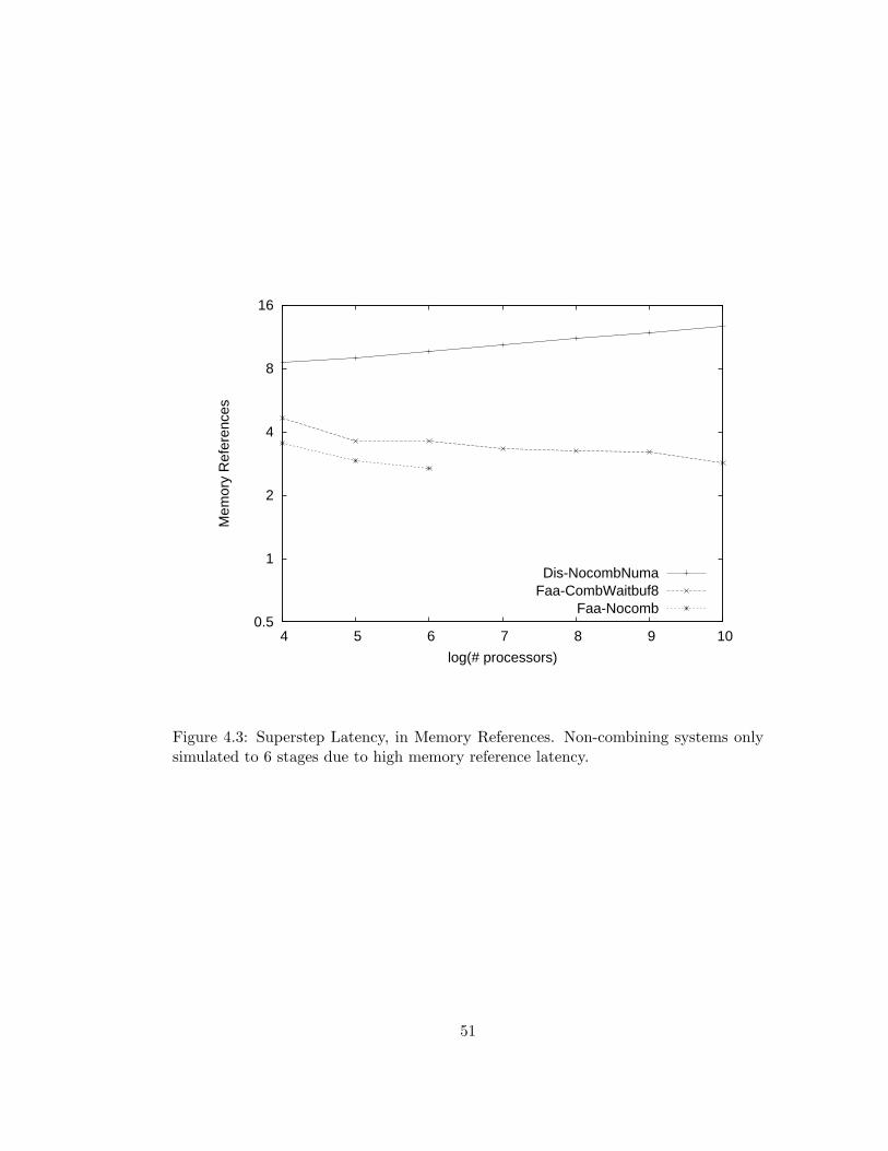
0.5
1
2
4
8
16
4 5 6 7 8 9 10
Mem
ory
Ref
eren
ces
log(# processors)
Dis-NocombNumaFaa-CombWaitbuf8
Faa-Nocomb
Figure 4.3: Superstep Latency, in Memory References. Non-combining systems onlysimulated to 6 stages due to high memory reference latency.
51
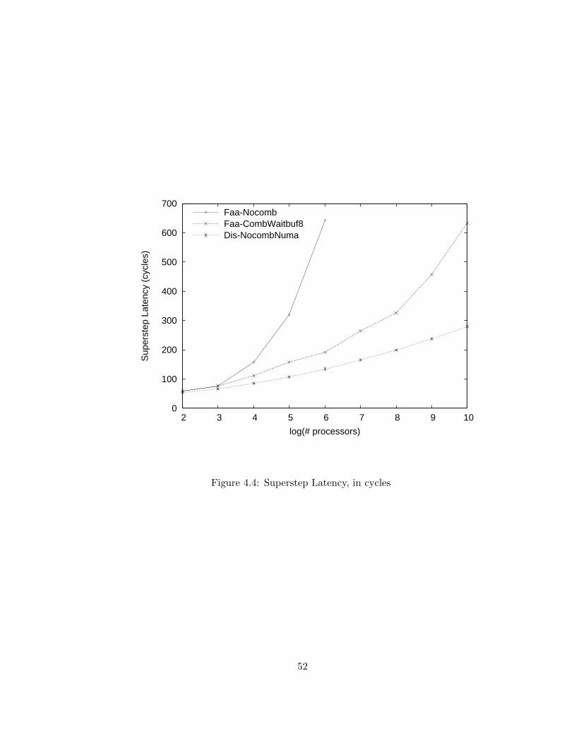
0
100
200
300
400
500
600
700
2 3 4 5 6 7 8 9 10
Sup
erst
ep L
aten
cy (
cycl
es)
log(# processors)
Faa-NocombFaa-CombWaitbuf8Dis-NocombNuma
Figure 4.4: Superstep Latency, in cycles
52

Chapter 5
Hot Spot Polling on Combining
Architectures
The previous chapter presented simulation results indicating poor performance
for centralized busy-waiting coordination algorithms on large Ultra3 systems
due to high memory latency. In this chapter, I investigate the high memory
latency for reference patterns typical of hot spot polling. A closer examination
of network behavior indicates that this high latency is largely due to the selection
of sub-optimal combining switch design parameters and to hot spot congestion
effects first observed by Kruskal et. al. (see [14]). Adjustment of of switch design
parameters and other enhancements to the Ultra3 combining switch design are
presented that together sigificantly reduce memory latency for hot spot reference
patterns.
53
5.1 Hot Spot Polling on the Ultra3 Architecture
The upper chart of Figure 5.1 is a plot of memory latency for simulated Ultra3
systems of varying sizes for a range of hot spot concentrations. In these “closed”
experiments, each processor issues a single memory reference eight cycles after
the previous memory reference completes, and therefore the system effectively
contains exactly one memory reference for each PE. Observe that, for low hot
spot concentrations, memory latency is dominated by network transmission time
(one cycle per network stage in each direction). However, memory latency is
substantially greater for higher hot spot concentrations. In particular, for large
systems, the 100% hot spot load, which simulates the reference pattern generated
by busy-wait polling of a centralized coordination variable, has latency more than
an order of magnitude greater than for uniform traffic (0% hotspot traffic).
Kruskal, Lee, and Kuck attribute this high latency to the large queuing de-
lays in switches near memory. Latency for memory references generated by the
polling of centralized variables increases significantly with queue capacity, result-
ing in conflicting design constraints since long queues are required to support
high-bandwidth uniform traffic loads (see Dickey [7], Liu [35]). These conflicting
requirements for queue characteristics force combining queue designs to trade
hot-spot traffic performance for uniform traffic performance.
My research indicates that, in addition to the effects observed by Kruskal et.
al, other design parameters of the Ultra3 switch further increase the latency of
memory references due to hot spot polling. Finally, modifications to the Ultra3
switch design are proposed that reduce latency for hot spot memory reference
54
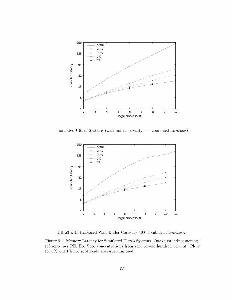
4
8
16
32
64
128
256
2 3 4 5 6 7 8 9 10
Rou
ndtr
ip L
aten
cy
log(# processors)
100%20%10%1%0%
Simulated Ultra3 Systems (wait buffer capacity = 8 combined messages)
4
8
16
32
64
128
256
2 3 4 5 6 7 8 9 10 11
Rou
ndtr
ip L
aten
cy
log(# processors)
100%20%10%1%0%
Ultra3 with Increased Wait Buffer Capacity (100 combined messages).
Figure 5.1: Memory Latency for Simulated Ultra3 Systems. One outstanding memoryreference per PE, Hot Spot concentrations from zero to one hundred percent. Plotsfor 0% and 1% hot spot loads are super-imposed.
55
patterns due to busy-wait polling.
Limed Wait Buffer Capacity Increases Polling Latency
Ultra3 switches have wait buffer capacities of eight combined messages per
forward-path switch port. The lack of an available wait buffer slot prevents the
transmission of a combined message. Simulation studies conducted by Susan
Dickey [7] indicated that this limited wait-buffer capacity was sufficient for high
bandwidth memory reference patterns of which 10% referenced a single hot-spot
variable and the remainder of the references were uniformly distributed.
However, this limited wait buffer capacity substantially increases memory la-
tency for the important case of memory reference patterns with 100% hot spot
accesses, which includes the important case of universal polling of a single loca-
tion (e.g. centralized barrier implementations). Reduced 100% hot spot latencies
for systems constructed with switches whose wait buffer capacities are generously
increased to one hundred messages is evident in the lower half of Figure 5.1 Sim-
ulation studies presented throughout the rest of this dissertation evaluate only
alternative switch designs with wait buffer capacities of one hundred messages.
Kruskal, Lee, and Kuck observed that memory traffic due to hotspot polling
can be modeled as a closed system of 2n fully combinable accesses1 and that such
fully combinable memory access patterns fill combining queues near to MMs [14].
I observe that the filling of these “downstream” queues effectively starves
upstream queues, thereby resulting in low queuing latency with infrequent com-
bining in upstream switches, and high latency with perfect combining in down-
1One access for each of the 2n PEs, where n is the depth of the combining network.
56

0
50
100
150
200
250
0 2 4 6 8 10 12
Com
bine
s / k
c
Distance to Memory
11108642
No combine limit — CombWaitbuf100
0
50
100
150
200
250
1 2 3 4 5 6 7 8 9 10
Com
bine
s / k
c
Distance to Memory
108642
Combine limit = 2 — CombThrot2Waitbuf100
Figure 5.2: Combining rate, by stage for simulated polling on systems of 22 to 211 PEs.Systems composed of simulated type “B” switches with wait buffer capacities of 100messages, and forward-path combining queue capacities of 4 combined or uncombinedmessages.
57
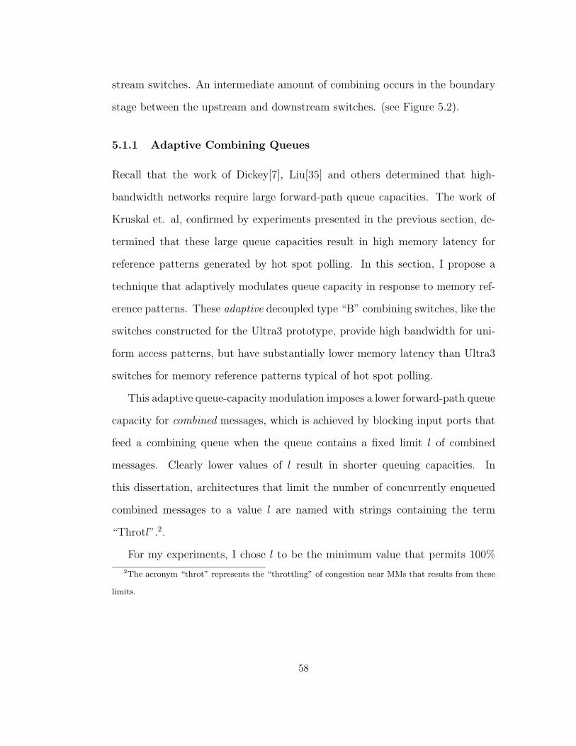
stream switches. An intermediate amount of combining occurs in the boundary
stage between the upstream and downstream switches. (see Figure 5.2).
5.1.1 Adaptive Combining Queues
Recall that the work of Dickey[7], Liu[35] and others determined that high-
bandwidth networks require large forward-path queue capacities. The work of
Kruskal et. al, confirmed by experiments presented in the previous section, de-
termined that these large queue capacities result in high memory latency for
reference patterns generated by hot spot polling. In this section, I propose a
technique that adaptively modulates queue capacity in response to memory ref-
erence patterns. These adaptive decoupled type “B” combining switches, like the
switches constructed for the Ultra3 prototype, provide high bandwidth for uni-
form access patterns, but have substantially lower memory latency than Ultra3
switches for memory reference patterns typical of hot spot polling.
This adaptive queue-capacity modulation imposes a lower forward-path queue
capacity for combined messages, which is achieved by blocking input ports that
feed a combining queue when the queue contains a fixed limit l of combined
messages. Clearly lower values of l result in shorter queuing capacities. In
this dissertation, architectures that limit the number of concurrently enqueued
combined messages to a value l are named with strings containing the term
“Throtl”.2.
For my experiments, I chose l to be the minimum value that permits 100%
2The acronym “throt” represents the “throttling” of congestion near MMs that results from these
limits.
58
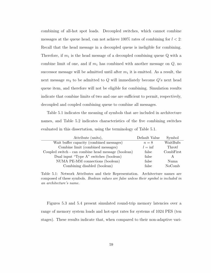
combining of all-hot spot loads. Decoupled switches, which cannot combine
messages at the queue head, can not achieve 100% rates of combining for l < 2:
Recall that the head message in a decoupled queue is ineligible for combining.
Therefore, if m1 is the head message of a decoupled combining queue Q with a
combine limit of one, and if m1 has combined with another message on Q, no
successor message will be admitted until after m1 it is emitted. As a result, the
next message m2 to be admitted to Q will immediately become Q’s next head
queue item, and therefore will not be eligible for combining. Simulation results
indicate that combine limits of two and one are sufficient to permit, respectively,
decoupled and coupled combining queue to combine all messages.
Table 5.1 indicates the meaning of symbols that are included in architecture
names, and Table 5.2 indicates characteristics of the five combining switches
evaluated in this dissertation, using the terminology of Table 5.1.
Attribute (units), Default Value SymbolWait buffer capacity (combined messages) n = 8 WaitBufn
Combine limit (combined messages) l = inf ThrotlCoupled switch - can combine head message (boolean) false CombFirst
Dual input “Type A” switches (boolean) false ANUMA PE-MM connections (boolean) false Numa
Combining disabled (boolean) false NoComb
Table 5.1: Network Attributes and their Representation. Architecture names arecomposed of these symbols. Boolean values are false unless their symbol is included inan architecture’s name.
Figures 5.3 and 5.4 present simulated round-trip memory latencies over a
range of memory system loads and hot-spot rates for systems of 1024 PES (ten
stages). These results indicate that, when compared to their non-adaptive vari-
59
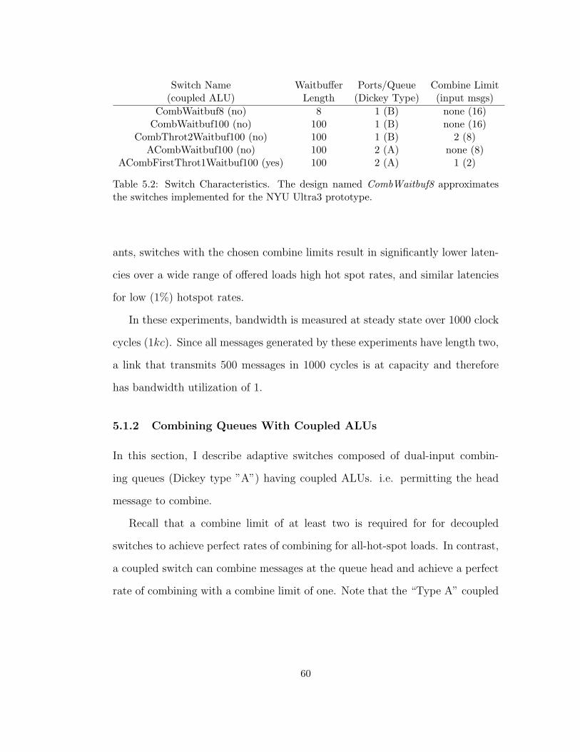
Switch Name Waitbuffer Ports/Queue Combine Limit(coupled ALU) Length (Dickey Type) (input msgs)
CombWaitbuf8 (no) 8 1 (B) none (16)CombWaitbuf100 (no) 100 1 (B) none (16)
CombThrot2Waitbuf100 (no) 100 1 (B) 2 (8)ACombWaitbuf100 (no) 100 2 (A) none (8)
ACombFirstThrot1Waitbuf100 (yes) 100 2 (A) 1 (2)
Table 5.2: Switch Characteristics. The design named CombWaitbuf8 approximatesthe switches implemented for the NYU Ultra3 prototype.
ants, switches with the chosen combine limits result in significantly lower laten-
cies over a wide range of offered loads high hot spot rates, and similar latencies
for low (1%) hotspot rates.
In these experiments, bandwidth is measured at steady state over 1000 clock
cycles (1kc). Since all messages generated by these experiments have length two,
a link that transmits 500 messages in 1000 cycles is at capacity and therefore
has bandwidth utilization of 1.
5.1.2 Combining Queues With Coupled ALUs
In this section, I describe adaptive switches composed of dual-input combin-
ing queues (Dickey type ”A”) having coupled ALUs. i.e. permitting the head
message to combine.
Recall that a combine limit of at least two is required for for decoupled
switches to achieve perfect rates of combining for all-hot-spot loads. In contrast,
a coupled switch can combine messages at the queue head and achieve a perfect
rate of combining with a combine limit of one. Note that the “Type A” coupled
60
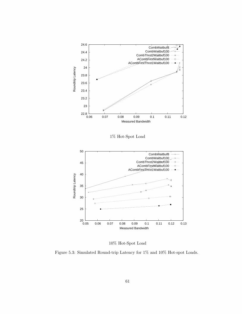
22.8
23
23.2
23.4
23.6
23.8
24
24.2
24.4
24.6
0.06 0.07 0.08 0.09 0.1 0.11 0.12
Rou
ndtr
ip L
aten
cy
Measured Bandwidth
CombWaitbuf8CombWaitbuf100
CombThrot2Waitbuf100ACombFirstWaitbuf100
ACombFirstThrot1Waitbuf100
1% Hot-Spot Load
20
25
30
35
40
45
50
0.05 0.06 0.07 0.08 0.09 0.1 0.11 0.12 0.13
Rou
ndtr
ip L
aten
cy
Measured Bandwidth
CombWaitbuf8CombWaitbuf100
CombThrot2Waitbuf100ACombFirstWaitbuf100
ACombFirstThrot1Waitbuf100
10% Hot-Spot Load
Figure 5.3: Simulated Round-trip Latency for 1% and 10% Hot-spot Loads.
61

20
30
40
50
60
70
80
90
0.03 0.04 0.05 0.06 0.07 0.08 0.09 0.1 0.11 0.12 0.13
Rou
ndtr
ip L
aten
cy
Measured Bandwidth
CombWaitbuf8CombWaitbuf100CombThrot2Waitbuf100ACombFirstWaitbuf100ACombFirstThrot1Waitbuf100
20% Hot-Spot Load
0
100
200
300
400
500
600
700
800
900
1000
0 0.02 0.04 0.06 0.08 0.1 0.12 0.14 0.16
Rou
ndtr
ip L
aten
cy
Measured Bandwidth
CombWaitbuf8CombWaitbuf100
CombThrot2Waitbuf100ACombFirstWaitbuf100
ACombFirstThrot1Waitbuf100
100% Hot-Spot Load
Figure 5.4: Simulated Round-trip Latency for 20% and 100% hot-spot loads.
62
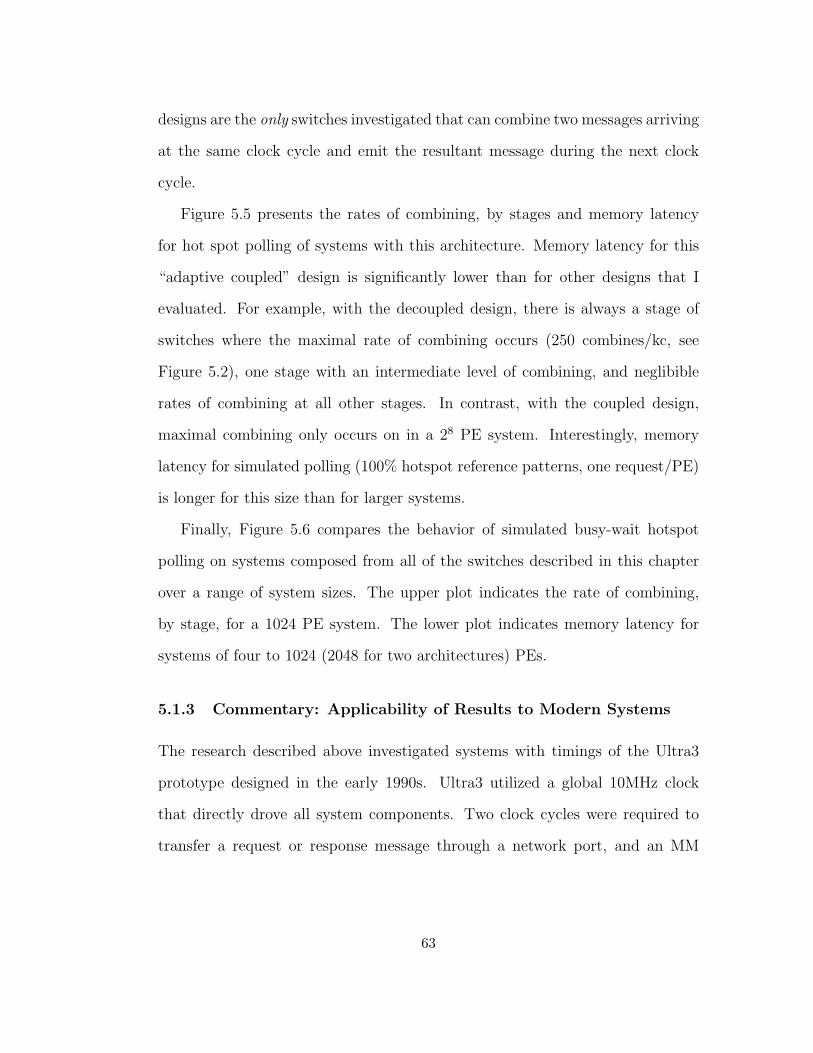
designs are the only switches investigated that can combine two messages arriving
at the same clock cycle and emit the resultant message during the next clock
cycle.
Figure 5.5 presents the rates of combining, by stages and memory latency
for hot spot polling of systems with this architecture. Memory latency for this
“adaptive coupled” design is significantly lower than for other designs that I
evaluated. For example, with the decoupled design, there is always a stage of
switches where the maximal rate of combining occurs (250 combines/kc, see
Figure 5.2), one stage with an intermediate level of combining, and neglibible
rates of combining at all other stages. In contrast, with the coupled design,
maximal combining only occurs on in a 28 PE system. Interestingly, memory
latency for simulated polling (100% hotspot reference patterns, one request/PE)
is longer for this size than for larger systems.
Finally, Figure 5.6 compares the behavior of simulated busy-wait hotspot
polling on systems composed from all of the switches described in this chapter
over a range of system sizes. The upper plot indicates the rate of combining,
by stage, for a 1024 PE system. The lower plot indicates memory latency for
systems of four to 1024 (2048 for two architectures) PEs.
5.1.3 Commentary: Applicability of Results to Modern Systems
The research described above investigated systems with timings of the Ultra3
prototype designed in the early 1990s. Ultra3 utilized a global 10MHz clock
that directly drove all system components. Two clock cycles were required to
transfer a request or response message through a network port, and an MM
63

0
50
100
150
200
250
1 2 3 4 5 6 7 8 9 10
Com
bine
s / k
c
Distance to Memory
10864
Rates of Combining, by Stage
4
8
16
32
2 3 4 5 6 7 8 9 10
Rou
ndtr
ip L
aten
cy
log(# processors)
20%10%1%0%100%
Memory Latency, 100% Hot Spot Polling Load
Figure 5.5: Memory latency and rates of combining at each network stage for simulatedbusy-wait loads on systems with switches of type “ACombFirstThrot1Waitbuf100”.Plots for systems of 4, 6, 8, and 10 stages. Unlike systems with decoupled single-inputswitches, significant rates of combining occur in stages near to processors. Saturatedrates of combining near to memory only occur on systems of eight stages, which hashigher memory latency. 64
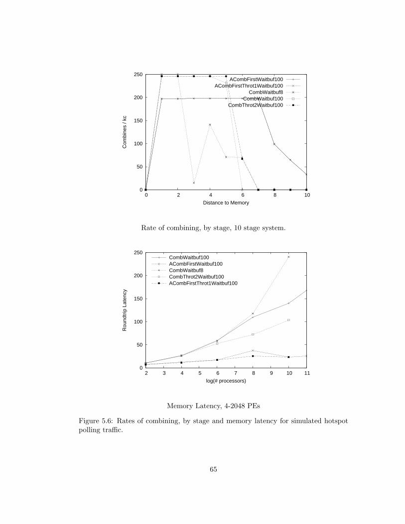
0
50
100
150
200
250
0 2 4 6 8 10
Com
bine
s / k
c
Distance to Memory
ACombFirstWaitbuf100ACombFirstThrot1Waitbuf100
CombWaitbuf8CombWaitbuf100
CombThrot2Waitbuf100
Rate of combining, by stage, 10 stage system.
0
50
100
150
200
250
2 3 4 5 6 7 8 9 10 11
Rou
ndtr
ip L
aten
cy
log(# processors)
CombWaitbuf100ACombFirstWaitbuf100CombWaitbuf8CombThrot2Waitbuf100ACombFirstThrot1Waitbuf100
Memory Latency, 4-2048 PEs
Figure 5.6: Rates of combining, by stage and memory latency for simulated hotspotpolling traffic.
65

could accept one request every four cycles. During the intervening decade, logic
and communication rates have increased by more than two orders of magnitude
over the intervening decade, however the latency of dynamic RAM has not even
been reduced by a factor of two.
Modern (ca 2003) implementations of the Ultra3 architecture would incor-
porate network and processor components two orders of magnitude faster than
those utilized for Ultra3. In contrast, RAM access latencies have remained es-
sentially constant. As a result, when compared to the 1990 Ultra3 design point
with PE and network speeds within an order of magnitude of each other, a mod-
ern MM that required a RAM access to satisfy each transaction would have a
relative access latency of approximately two orders-of-magnitude slower than the
Ultra3 design.
Figure 5.7 indicates that the advantages of adaptive switch designs are greater
for systems with slow MMs. In this plot, the same switch architectures are
connected to MMs an order-of-magnitude slower than the MMs constructed for
Ultra3.
As demonstrated above, minimization of queue length using the adaptive
technique is useful for reducing the round-trip latency of memory transactions
generated by busy-wait polling on large parallel systems with combining net-
works.
In addition, a network constructed of current (ca. 2003) technologies could
deliver memory references approximately one hundred times faster than the ser-
vice rate of RAM core. Potential approaches for achieving similarly high MM
service rates could include interleaved RAM banks at MMs and physical memory
66

caches at MMs. The former approach would be suitable for uniformly distributed
traffic; the latter approach would be well suited for the temporal locality of hot
spot accesses.
5.1.4 Architectures Used in Evaluation of Busy-Waiting Coordina-
tion Algorithms
The remainder of my dissertation is an evaluation of several algorithms for
readers-writers and barrier coordination. These evaluations includes simulation
results both on systems serializing hot-spot access and systems that support
combining.
Non-uniform memory architectures (NUMA), which co-locate each MM with
a PE are exploited by some algorithms: For these experiments, the simulator is
configured to pair PEn with MMn. Simulated memory transactions within such
a PE-MM pairing require only a single cycle and do not generate any network
contention.
The remaining chapters of this dissertation examine the performance of cen-
tralized and distributed busy-waiting on Ultracomputers enhanced with adaptive
combining switches. Two designs of adaptive switches listed in Table 5.1 are uti-
lized for these experiments:
• “CombThrot2Waitbuf100”: A decoupled, adaptive, type “B” switch, which,
for the remainder of this dissertation, is more casually referred to as “De-
coupled Adaptive”.
• “ACombFirstThrot1Waitbuf100”: A coupled, adaptive, type “A” switch,
67
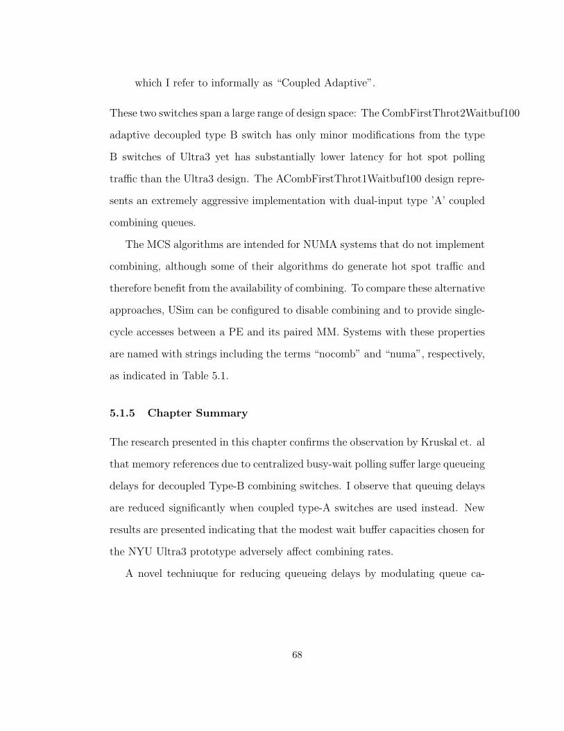
which I refer to informally as “Coupled Adaptive”.
These two switches span a large range of design space: The CombFirstThrot2Waitbuf100
adaptive decoupled type B switch has only minor modifications from the type
B switches of Ultra3 yet has substantially lower latency for hot spot polling
traffic than the Ultra3 design. The ACombFirstThrot1Waitbuf100 design repre-
sents an extremely aggressive implementation with dual-input type ’A’ coupled
combining queues.
The MCS algorithms are intended for NUMA systems that do not implement
combining, although some of their algorithms do generate hot spot traffic and
therefore benefit from the availability of combining. To compare these alternative
approaches, USim can be configured to disable combining and to provide single-
cycle accesses between a PE and its paired MM. Systems with these properties
are named with strings including the terms “nocomb” and “numa”, respectively,
as indicated in Table 5.1.
5.1.5 Chapter Summary
The research presented in this chapter confirms the observation by Kruskal et. al
that memory references due to centralized busy-wait polling suffer large queueing
delays for decoupled Type-B combining switches. I observe that queuing delays
are reduced significantly when coupled type-A switches are used instead. New
results are presented indicating that the modest wait buffer capacities chosen for
the NYU Ultra3 prototype adversely affect combining rates.
A novel techniuque for reducing queueing delays by modulating queue ca-
68
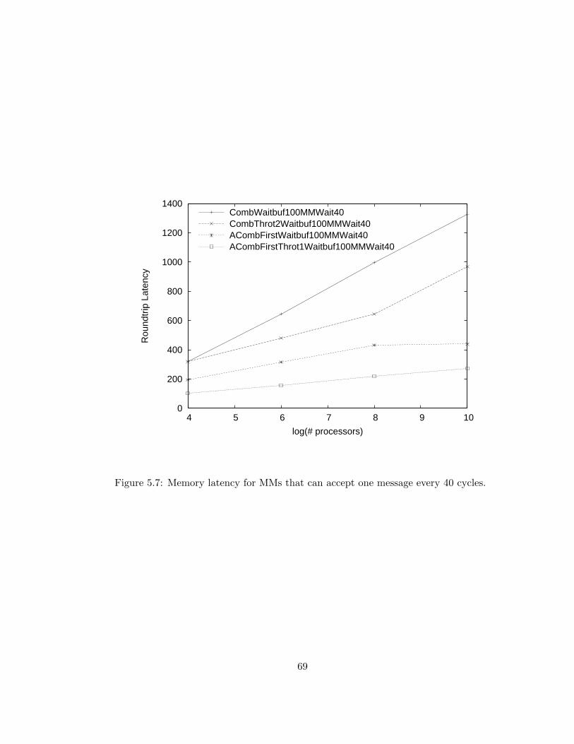
0
200
400
600
800
1000
1200
1400
4 5 6 7 8 9 10
Rou
ndtr
ip L
aten
cy
log(# processors)
CombWaitbuf100MMWait40CombThrot2Waitbuf100MMWait40ACombFirstWaitbuf100MMWait40ACombFirstThrot1Waitbuf100MMWait40
Figure 5.7: Memory latency for MMs that can accept one message every 40 cycles.
69

pacity has been demonstrated to significantly reduce the latency of memory
references generated by centralized polling. I did not investigate high rates of
random traffic with low levels of hot-spot references, nor polling traffic directed
toward mutiple hot spots. It is possible that the fixed effective queue lengths
triggered by the adaptive technique described above will be shorter than nec-
essary to achieve good performance for these loads. If so, a progressive cutoff
computed as a function of recent combining activity may yield superior results
for some of these reference patterns.
The relative speeds of MMs and network components would be dramatically
different if an Ultracomputer was constructed using current technologies. In
particular, MMs whose bandwidth for random accesses is significantly slower
than network links cause queueing delays in switches near to memory. Simulation
results using slow MMs (µ = 40) presented in this chapter indicate that the
adaptive queue length modulation technique remans effective.
70
Chapter 6
Barrier Coordination
This chapter includes the first analytical model of latency of barrier coordina-
tion algorithms, and continues the simulation study of Chapter 4 that compares
scalability of distributed barrier algorithms with centralized barrier algorithms
on systems that implement hardware combining.
In this section, the latency of several centralized bottleneck-free algorithms
for barrier coordination that exploit the combining of fetch-and-add operations
are compared with the latency of the MCS dissemination barrier algorithm. This
investigation includes both analytical and simulation studies that characterize
superstep latency for all of these algorithms. The simulation studies generate
three simulated workloads and are executed on systems with the adaptive type
“A” and “B” switches described in the preceding chapter. Analytical results are
consistent with measured performance.
The centralized self-cleaning algorithms for barrier coordination described in
this chapter utilize shared counters that are incremented as processes complete
71
a superstep. These algorithms illustrate a variety of techniques for determining
and disseminating notification of the completion of a superstep, and cleaning of
the barrier for subsequent supersteps. These techniques include:
• Master-slave approaches in which a single process is designated “barrier
leader” and is responsible for detecting superstep completion and resetting
variables for subsequent supersteps, and “self-service” approaches where no
such leader process is designated.
• Amortizing the cost of reseting state variables over multiple supersteps.
• Reducing the number of shared accesses by encoding multiple state vari-
ables in a single memory word.
• Adapting to systems that support fetch-and-add only with unit addends
(e.g. fetch-and-increment).
Each of these techniques exposes a design trade-off. For example:
• Algorithms that require fetch-and-add with only unit addends increase the
number of shared accesses on all process’ critical path when cleaning is
performed, and
• Algorithms that amortize cleaning over multiple supersteps are more com-
plex and therefore require more computation.
This chapter’s simulation results demonstrate that, on on large systems, the
latency of these algorithms is dominated by the number of shared accesses on
their critical paths. Algorithms with superior performance generally utilize sev-
eral of these techniques.
72

6.1 A Single-Use Barrier
Several generations of centralized bottleneck-free algorithms for barrier coordi-
nation were discovered over a fifteen year period by the NYU Ultracomputer
Research Group. Early algorithms are elegant in their simplicity; later versions
introduced optimizations that reduced the number of shared memory references
on the critical path from super-step completion to commencement of a subse-
quent computation. I present several representatives of this lineage that illustrate
the incremental development of these techniques, and provide a gentle introduc-
tion to the optimizations utilized in later algorithms.
All of these algorithms utilize shared counters manipulated by fetch-and-add
to determine when a super-step is complete. Several techniques were utilized to
detect and disseminate notification of super-step completion and to prepare the
count for future super-steps. A barrier algorithm that completes super-step n
with its state variables prepared for the execution of super-step n+1 is described
as reusable or self-cleaning.
A non-reusable centralized barrier algorithm that I refer to as OneUseBar-
rier appears in Figure 6.1. OneUseBarrier uses a single shared integer counter
(Count) whose initial value is zero. Count is manipulated by an atomic fetch-
and-increment (denoted as FAI, and functionally equivalent to a fetch-and-add
with a fixed addend of 1). In this and other algorithms described in this chapter,
a constant PAR = 2stages processes are participating in the barrier coordination.
Each process increments Count when they complete their super-step. All
PAR processes participating the super-step busy-wait wait until the count’s
73
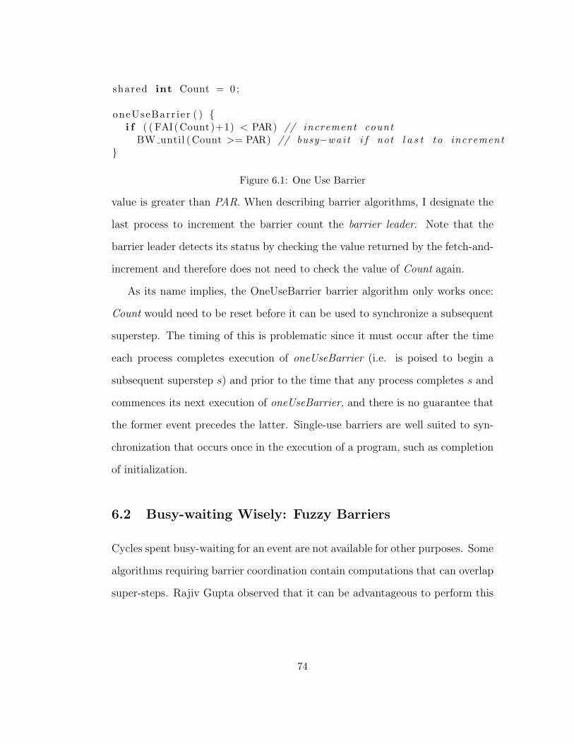
shared int Count = 0 ;
oneUseBarr ier ( ) {i f ( ( FAI(Count)+1) < PAR) // increment count
BW until (Count >= PAR) // busy−wai t i f not l a s t to increment}
Figure 6.1: One Use Barrier
value is greater than PAR. When describing barrier algorithms, I designate the
last process to increment the barrier count the barrier leader. Note that the
barrier leader detects its status by checking the value returned by the fetch-and-
increment and therefore does not need to check the value of Count again.
As its name implies, the OneUseBarrier barrier algorithm only works once:
Count would need to be reset before it can be used to synchronize a subsequent
superstep. The timing of this is problematic since it must occur after the time
each process completes execution of oneUseBarrier (i.e. is poised to begin a
subsequent superstep s) and prior to the time that any process completes s and
commences its next execution of oneUseBarrier, and there is no guarantee that
the former event precedes the latter. Single-use barriers are well suited to syn-
chronization that occurs once in the execution of a program, such as completion
of initialization.
6.2 Busy-waiting Wisely: Fuzzy Barriers
Cycles spent busy-waiting for an event are not available for other purposes. Some
algorithms requiring barrier coordination contain computations that can overlap
super-steps. Rajiv Gupta observed that it can be advantageous to perform this
74

work after the count is incremented and before commencing busy-waiting because
useful work is performed during time that might have otherwise been wasted
without delaying the progress of other processes engaged in the coordination
[43].
The algorithm fuzzyOneUseBarrier (below) incorporates Gupta’s fuzzy bar-
rier technique: Consider some computation represented by the function fuzzy-
Work(), which must be executed by all processes participating in barrier coor-
dination and can be performed asynchronously of the barrier, and some process
P executing barrier coordination algorithm fuzzyOneUseBarrier. Assume that
P completes its superstep at some time t, and that at least one other process
will not arrive at the barrier until some time t′ > t. Note that if the barrier
was enforced by oneUseBarrier, P would busy-wait during the interval t...t′,
accomplishing no useful work.
Rather than immediately busy-waiting until after last process increments
count (after t’), Gupta suggests that P should instead execute useful work rep-
resented by doFuzzyWork. P commences polling only after doFuzzyWork has
completed, thus reducing (or eliminating) wasted polling time. Note that no
other process’s progress is impeded by P’s execution of doFuzzyWork.
When no work overlaps the barrier, fuzzyWork() is empty and can be op-
timized away. For clarity, the algorithms described below are coded without
fuzzyWork sections. Alternate versions of several of these algorithms that in-
clude support for fuzzy barriers appear in Appendix C.
75

shared int Count = 0 ;
fuzzyOneUseBarr ier ( ) {int v = FAI(Count ) + 1 ;doFuzzyWork ( ) ;i f ( v >= PAR)
BW until (Count >= PAR) ;}
Figure 6.2: Fuzzy One-Use Barrier
for ( int super s t ep = 0 ; super s t ep < numSuperSteps ; super s t ep++) {doWork( super s t ep ) ;b a r r i e r ( )
}
Figure 6.3: Repeated super-step loop executed by all processes participating in barriercoordination.
6.3 Reusable (Self-cleaning) Barriers
Barriers used for multi-step bulk-synchronous computation must automatically
reset their count between iterations without re-initialization. Algorithms with
this property are termed reusable or self-cleaning. Unlike oneUseBarrier, all
algorithms for barrier coordination evaluated below are reusable. For example,
the looping program in in Figure 6.3 requires that the implementation of barrier()
be self-cleaning:
In his dissertation, Clyde Kruskal [31] observes that a naive self-cleaning
extension of oneUseBarrier such as the one that appears in Figure 6.4 is incorrect
since it contains a race condition (between the resetting of count and the fetch-
and-increment) that can lead to deadlock.
The remainder of the algorithms presented below implement self-cleaning
76
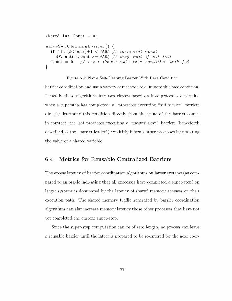
shared int Count = 0 ;
na i v eS e l fC l e an ingBa r r i e r ( ) {i f ( f a i (&Count)+1 < PAR) // increment Count
BW until (Count >= PAR) // busy−wai t i f not l a s tCount = 0 ; // r e s e t Count ; note race cond i t i on wi th f a i
}
Figure 6.4: Naive Self-Cleaning Barrier With Race Condition
barrier coordination and use a variety of methods to eliminate this race condition.
I classify these algorithms into two classes based on how processes determine
when a superstep has completed: all processes executing “self service” barriers
directly determine this condition directly from the value of the barrier count;
in contrast, the last processes executing a “master slave” barriers (henceforth
described as the “barrier leader”) explicitly informs other processes by updating
the value of a shared variable.
6.4 Metrics for Reusable Centralized Barriers
The excess latency of barrier coordination algorithms on larger systems (as com-
pared to an oracle indicating that all processes have completed a super-step) on
larger systems is dominated by the latency of shared memory accesses on their
execution path. The shared memory traffic generated by barrier coordination
algorithms can also increase memory latency those other processes that have not
yet completed the current super-step.
Since the super-step computation can be of zero length, no process can leave
a reusable barrier until the latter is prepared to be re-entered for the next coor-
77
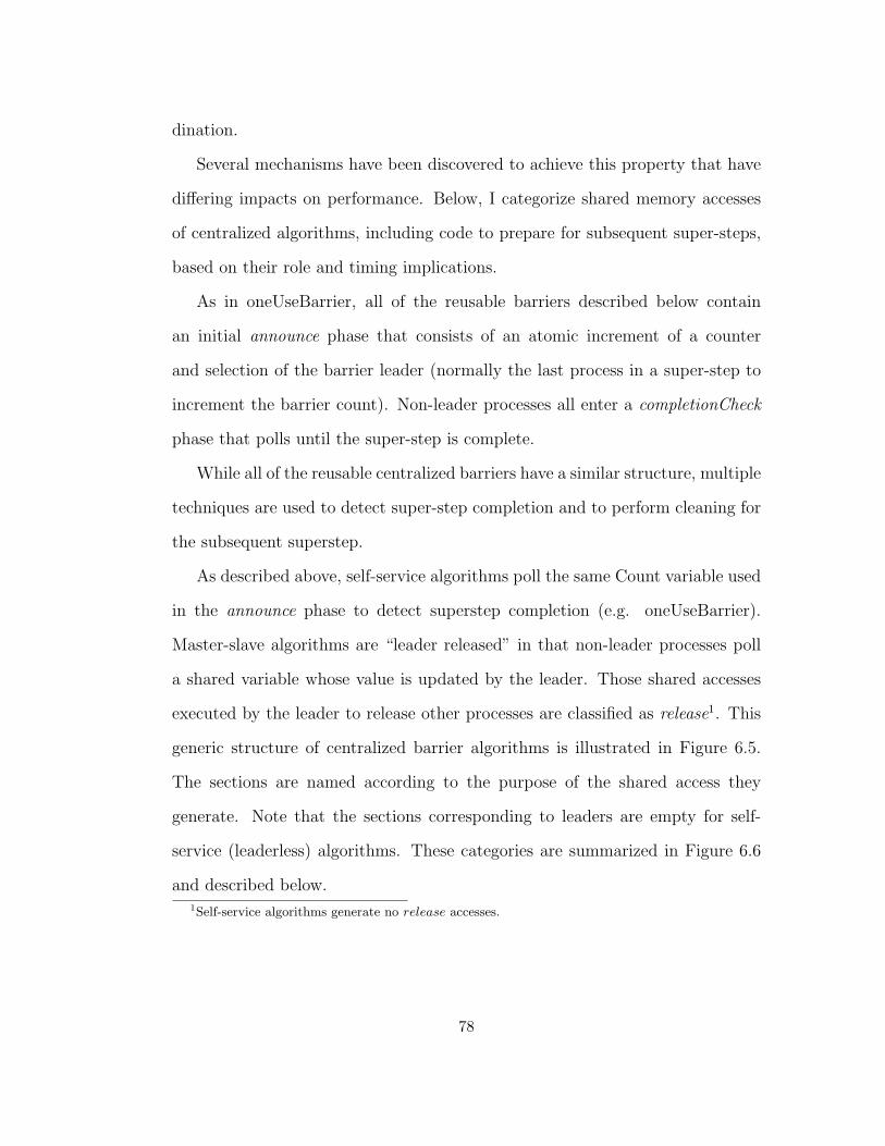
dination.
Several mechanisms have been discovered to achieve this property that have
differing impacts on performance. Below, I categorize shared memory accesses
of centralized algorithms, including code to prepare for subsequent super-steps,
based on their role and timing implications.
As in oneUseBarrier, all of the reusable barriers described below contain
an initial announce phase that consists of an atomic increment of a counter
and selection of the barrier leader (normally the last process in a super-step to
increment the barrier count). Non-leader processes all enter a completionCheck
phase that polls until the super-step is complete.
While all of the reusable centralized barriers have a similar structure, multiple
techniques are used to detect super-step completion and to perform cleaning for
the subsequent superstep.
As described above, self-service algorithms poll the same Count variable used
in the announce phase to detect superstep completion (e.g. oneUseBarrier).
Master-slave algorithms are “leader released” in that non-leader processes poll
a shared variable whose value is updated by the leader. Those shared accesses
executed by the leader to release other processes are classified as release1. This
generic structure of centralized barrier algorithms is illustrated in Figure 6.5.
The sections are named according to the purpose of the shared access they
generate. Note that the sections corresponding to leaders are empty for self-
service (leaderless) algorithms. These categories are summarized in Figure 6.6
and described below.1Self-service algorithms generate no release accesses.
78

ba r r i e r ( ) {i f ( Announce ) // increment count , determine i f l e ade r
PreReleaseClean // prepara t ion to r e l e a s e b a r r i e rRelease // a l l ow o the r s to proceedPostReleaseClean // c l ean up ( r e s e t counts )
} else { // not l e ade rBW until ( o k t o l e av e ) // p o l l
}}
Figure 6.5: Generic Structure of Centralized Barrier Algorithms
Announce. Incrementing the shared counter to announce that this process has be-
gun executing the barrier. Some algorithms identify the last process to execute an-
nounce code as barrier leader. Announce operations are on the critical path of all
participating processes.
PreReleaseClean. Shared accesses issued by the leader process prior to releasing
non-leader processes.
Release. A shared access executed by the leader process that allows non-leader
processes to proceed.
PostReleaseClean. Shared accesses issued by the leader process after non-leader
processes may proceed.
Poll. Shared accesses issued by non-leader processes while polling to determine if
they can exit the barrier.
Figure 6.6: Classification of shared references by centralized barrier algorithms
79

Prior to executing release accesses, leader processes are guaranteed exclusive
access to the barrier count. This guaranteed exclusive access is exploited by
several of the algorithms described below to reset the count. Unfortunately,
these preReleaseClean accesses are on the critical path of the release of non-
leader processes and therefore delay all processes participating in the barrier.
Some algorithms utilize techniques for resetting the barrier count that can
be executed concurrently with other process’s announce for the subsequent su-
perstep. These postReleaseClean accesses, which follow the release, do not delay
other processes in this execution of the barrier.
Most centralized algorithms described below do not generate memory refer-
ences of all five categories. However, all centralized algorithms generate at least
one access to Announce superstep completion and to poll for barrier satisfaction.
In order to facilitate the timing analysis of centralized coordination algo-
rithms, I define the “barrier latency” as the interval between tbegin, when the
last process begins its ith execution of the barrier algorithm and tend, when the
first process completes its ith execution.
The first statement of all centralized barriers described in this dissertation
is a fetch-and-increment of a shared counter that establishes both the number
of processes that have commenced execution and their order. Due to its role in
publically registering the completion of the superstep by each process, I refer to
this statement as “announce.”
Leaving little to the imagination, I supply directed edges in Figure 6.7 to
indicate dependencies among groups of shared accesses (represented by ovals)
generated by of centralized barrier algorithms.
80
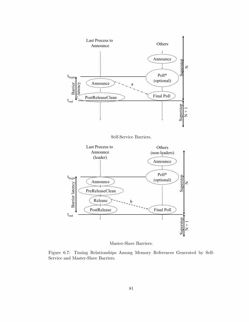
Poll*(optional)
Final Poll
Last Process to Announce Others
Announce
Supe
rste
pN
Supe
rste
pN
+ 1
Bar
rier
late
ncy Announce
PostReleaseClean
a
tbegin
tend
Self-Service Barriers.
Poll*(optional)
Final Poll
Last Process to Announce
(leader)
Others(non-leaders)
Announce
Supe
rste
pN
Supe
rste
pN
+ 1
Bar
rier l
aten
cy Announce
PreReleaseClean
Release
PostRelease
b
tbegin
tend
Master-Slave Barriers.
Figure 6.7: Timing Relationships Among Memory References Generated by Self-Service and Master-Slave Barriers.
81
The execution sequence of the “leader”, (the last process that executes the
announce fetch-and-increment operation) is portrayed in the left column; the
execution sequence of other processes (that executed their “announce” earlier)
is portrayed in the right column. The latter processes are called non-leaders, and
may have executed their polling phases multiple times in the interval between
their announcement and tbegin. Edges a and b indicate the dependency of each
non-leader’s final poll on the leader’s execution, for leaderless (self-service) and
leader-released (master-slave) algorithms respectively. All processes have com-
menced execution of superstep N + 1 at time tend, when the barrier is complete.
All useful computation for superstep N is completed prior to tbegin and all
processes have commenced superstep N + 1 at tend. I define this inter-superstep
delay tend − tbegin as the barrier latency.
The following properties are apparent from this structure:
• Announce, PreReleaseClean, and Release (when applicable) accesses are
on the critical paths of all processes.
• Poll and PostReleaseClean (when applicable) accesses can be executed
concurrently.
More formally, I define the minimum latency of an algorithm to enforce bar-
rier coordination as the minimum number (over all execution sequences) of lin-
early dependent shared accesses that occur between the time that the last process
executing a particular superstep issues the fetch-and-add “announcing” its ar-
rival at a barrier, and the time that the the first process terminates its execution
of this execution of the barrier algorithm. When modeling program behavior,
82
I assume a PRAM model, where the latency of concurrent memory accesses by
multiple processes are charged as a single access. Experimental results indicate
that these modeled minimum latencies correspond to measured latencies (on
non-PRAM systems) if the modeled latency is scaled by the latency of hot spot
references.
For each phase P of a barrier algorithm, I define LatencyP as the minimum
number of shared accesses generated by phase P , and define LatencynonLeader
and Latencyleader to be (respectively) the minimum numbers of sequentially de-
pendent shared accesses on the execution path of leader and non-leader pro-
cess. For leader-released barrier algorithms, non-leader processes must wait un-
til the leader releases the barrier. Therefore, LatencynonLeader includes both
LatencyPreReleaseClean and LatencyRelease:
Latencyleader = LatencyAnnounce + LatencyPreReleaseClean + LatencyRelease +
LatencyPostReleaseClean
LatencynonLeader = LatencyAnnounce+LatencyPreReleaseClean+LatencyRelease+
LatencyPoll
Finally, the modeled minimum latency, in shared accesses of a centralized
barrier algorithm is: LatencyAlgorithm = max(Latencyleader, LatencynonLeader)
This characterization of barrier execution latency, measured in shared ac-
cesses is used in my analysis of shared-memory algorithms. As described in
prior chapters, hot-spot memory references have an expected latency greater
than non-hot-spot (uniform) accesses that varies with architecture. Therefore, I
83
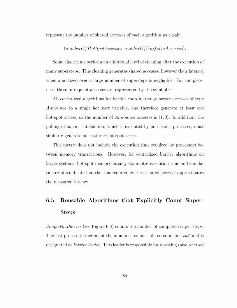
represent the number of shared accesses of each algorithm as a pair
(numberOfHotSpotAccesses, numberOfUniformAccesses).
Some algorithms perform an additional level of cleaning after the execution of
many supersteps. This cleaning generates shared accesses, however their latency,
when amortized over a large number of supersteps is negligible. For complete-
ness, these infrequent accesses are represented by the symbol ε.
All centralized algorithms for barrier coordination generate accesses of type
Announce to a single hot spot variable, and therefore generate at least one
hot-spot access, so the number of Announce accesses is (1, 0). In addition, the
polling of barrier satisfaction, which is executed by non-leader processes, must
similarly generate at least one hot-spot access.
This metric does not include the execution time required by processors be-
tween memory transactions. However, for centralized barrier algorithms on
larger systems, hot-spot memory latency dominates execution time and simula-
tion results indicate that the time required by these shared accesses approximates
the measured latency.
6.5 Reusable Algorithms that Explicitly Count Super-
Steps
SimpleFaaBarrier (see Figure 6.8) counts the number of completed super-steps.
The last process to increment the announce count is detected at line sb3, and is
designated as barrier leader. This leader is responsible for resetting (also referred
84
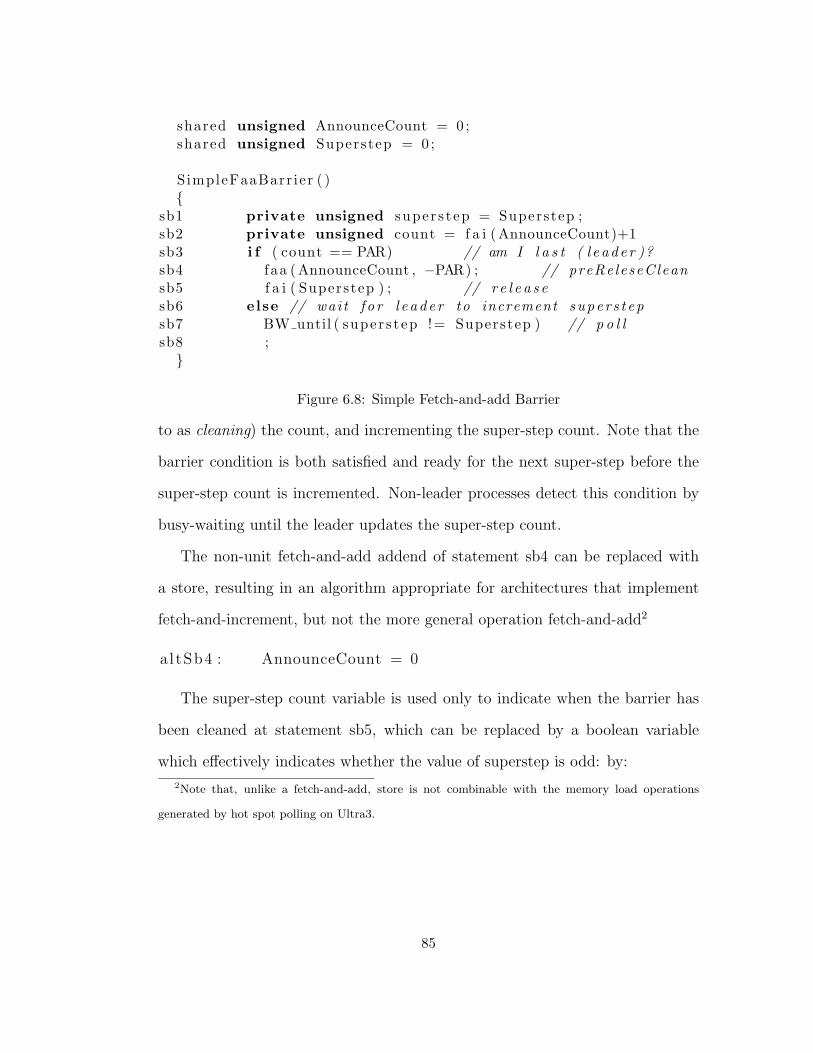
shared unsigned AnnounceCount = 0 ;shared unsigned Superstep = 0 ;
SimpleFaaBarr ier ( ){
sb1 private unsigned super s t ep = Superstep ;sb2 private unsigned count = f a i (AnnounceCount)+1sb3 i f ( count == PAR) // am I l a s t ( l e ade r )?sb4 faa (AnnounceCount , −PAR) ; // preReleseCleansb5 f a i ( Superstep ) ; // r e l e a s esb6 else // wai t f o r l e ade r to increment super s t epsb7 BW until ( super s t ep != Superstep ) // p o l lsb8 ;
}
Figure 6.8: Simple Fetch-and-add Barrier
to as cleaning) the count, and incrementing the super-step count. Note that the
barrier condition is both satisfied and ready for the next super-step before the
super-step count is incremented. Non-leader processes detect this condition by
busy-waiting until the leader updates the super-step count.
The non-unit fetch-and-add addend of statement sb4 can be replaced with
a store, resulting in an algorithm appropriate for architectures that implement
fetch-and-increment, but not the more general operation fetch-and-add2
a l tSb4 : AnnounceCount = 0
The super-step count variable is used only to indicate when the barrier has
been cleaned at statement sb5, which can be replaced by a boolean variable
which effectively indicates whether the value of superstep is odd: by:
2Note that, unlike a fetch-and-add, store is not combinable with the memory load operations
generated by hot spot polling on Ultra3.
85
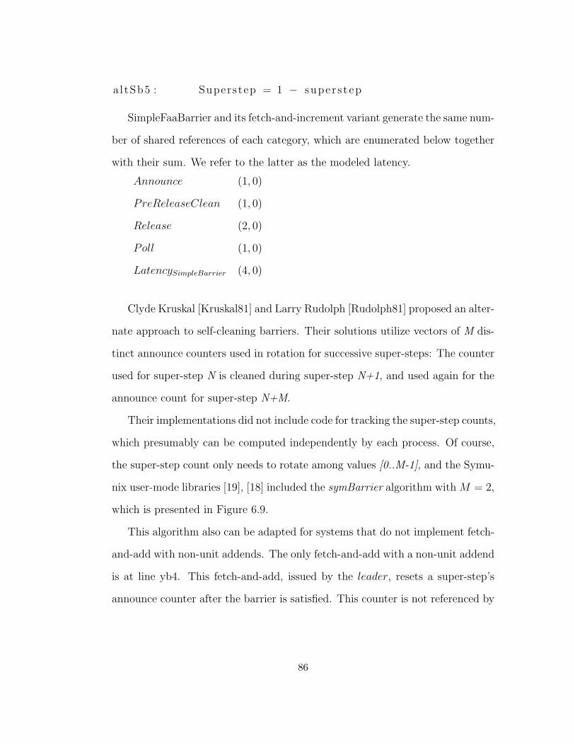
a l tSb5 : Superstep = 1 − super s t ep
SimpleFaaBarrier and its fetch-and-increment variant generate the same num-
ber of shared references of each category, which are enumerated below together
with their sum. We refer to the latter as the modeled latency.
Announce (1, 0)
PreReleaseClean (1, 0)
Release (2, 0)
Poll (1, 0)
LatencySimpleBarrier (4, 0)
Clyde Kruskal [Kruskal81] and Larry Rudolph [Rudolph81] proposed an alter-
nate approach to self-cleaning barriers. Their solutions utilize vectors of M dis-
tinct announce counters used in rotation for successive super-steps: The counter
used for super-step N is cleaned during super-step N+1, and used again for the
announce count for super-step N+M.
Their implementations did not include code for tracking the super-step counts,
which presumably can be computed independently by each process. Of course,
the super-step count only needs to rotate among values [0..M-1], and the Symu-
nix user-mode libraries [19], [18] included the symBarrier algorithm with M = 2,
which is presented in Figure 6.9.
This algorithm also can be adapted for systems that do not implement fetch-
and-add with non-unit addends. The only fetch-and-add with a non-unit addend
is at line yb4. This fetch-and-add, issued by the leader, resets a super-step’s
announce counter after the barrier is satisfied. This counter is not referenced by
86
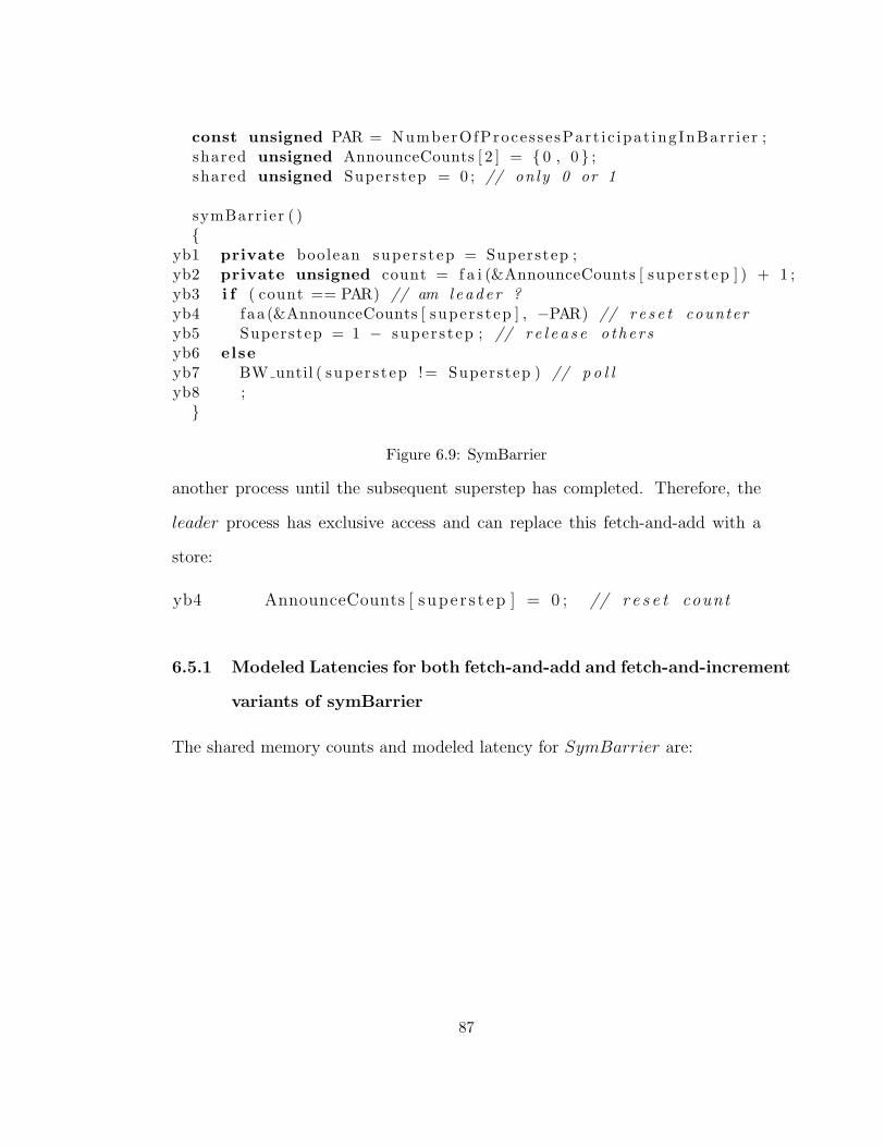
const unsigned PAR = NumberOfProces se sPart i c ipat ingInBarr i e r ;shared unsigned AnnounceCounts [ 2 ] = { 0 , 0 } ;shared unsigned Superstep = 0 ; // only 0 or 1
symBarrier ( ){
yb1 private boolean super s t ep = Superstep ;yb2 private unsigned count = f a i (&AnnounceCounts [ super s t ep ] ) + 1 ;yb3 i f ( count == PAR) // am l eade r ?yb4 faa (&AnnounceCounts [ super s t ep ] , −PAR) // r e s e t counteryb5 Superstep = 1 − super s t ep ; // r e l e a s e o the r syb6 elseyb7 BW until ( super s t ep != Superstep ) // p o l lyb8 ;
}
Figure 6.9: SymBarrier
another process until the subsequent superstep has completed. Therefore, the
leader process has exclusive access and can replace this fetch-and-add with a
store:
yb4 AnnounceCounts [ super s t ep ] = 0 ; // r e s e t count
6.5.1 Modeled Latencies for both fetch-and-add and fetch-and-increment
variants of symBarrier
The shared memory counts and modeled latency for SymBarrier are:
87
Announce (1, 0)
PreReleaseClean (1, 0)
Release (1, 0)
PostReleaseClean (0, 0)
SatifactionCheck (1, 0)
LatencySymBarrier (4, 0)
Since the counter used for even super-steps is not referenced during odd
super-steps, the cleaning step can be executed after rather than before non-
leader processes are released. Therefore, statements yb4 and yb5 can be inter-
changed, reducing the shared memory counts for the resulting algorithm (called
symBarrierI) to:
Announce (1, 0)
PreReleaseClean (0, 0)
Release (1, 0)
PostReleaseClean (1, 0)
SatifactionCheck (1, 0)
LatencySymBarrierI (3, 0)
6.6 Barriers suitable for Dynamic Groups
The group-lock technique of Dimitrovsky [DimitrovskyGroupLockRef] provides
a mechanism for dynamically forming groups of processes which can synchronize
using barrier coordination. In this model of computation, the number of pro-
cesses participating in the barrier can change dynamically. The barrier count
88
in symBarrier (and its fetch-and-increment variant) is computed independently
for each super-step and is therefore suitable for this application. A fetch-and-
increment variant of symBarrier is presented in my paper with Gottlieb [FG91]
to implement a group-lock barrier.
6.7 Reducing Release Latencies by Eliminating the Super-
step Count
In [9], Dimitrovsky proposes a single-variable algorithm for barrier coordination
presented in Figure 6.10. This algorithm eliminates the super-step counter by
only resetting the announce counter after even super-steps, thus cycling its value
through the range 0..PAR-1 for odd super-steps, and PAR..2PAR-1 for even
stages. This algorithm requires no release accesses for odd super-steps; on even
super-steps, non-leader processes wait until the leader releases them by resetting
the counter. No additional references are required to clean the barrier for the
next super-step.
This algorithm clears AnnounceCount only during alternate super-steps, with
a single shared access that is on the critical path for other processes’ Poll. There-
fore, the amortized release latency, measured in memory references, is (0.5, 0).
This technique of amortizing the cost of cleaning over two supersteps is extended
to larger numbers of supersteps by algorithms I designate as “lazy-clean” and
describe later in this chapter.
My paper with Gottlieb[12] on process coordination with fetch-and-increment
presents a variant of Dimitrovsky’s faaBarrier algorithm dubbed faiBarrier that
89
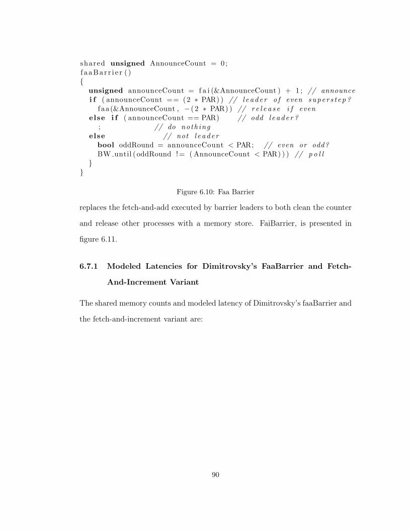
shared unsigned AnnounceCount = 0 ;f a aBa r r i e r ( ){
unsigned announceCount = f a i (&AnnounceCount ) + 1 ; // announcei f ( announceCount == (2 ∗ PAR) ) // l e ade r o f even super s t ep ?
f aa (&AnnounceCount , − ( 2 ∗ PAR) ) // r e l e a s e i f evenelse i f ( announceCount == PAR) // odd l e ade r ?
; // do noth ingelse // not l e ade r
bool oddRound = announceCount < PAR; // even or odd?BW until ( oddRound != ( AnnounceCount < PAR) ) ) // p o l l
}}
Figure 6.10: Faa Barrier
replaces the fetch-and-add executed by barrier leaders to both clean the counter
and release other processes with a memory store. FaiBarrier, is presented in
figure 6.11.
6.7.1 Modeled Latencies for Dimitrovsky’s FaaBarrier and Fetch-
And-Increment Variant
The shared memory counts and modeled latency of Dimitrovsky’s faaBarrier and
the fetch-and-increment variant are:
90
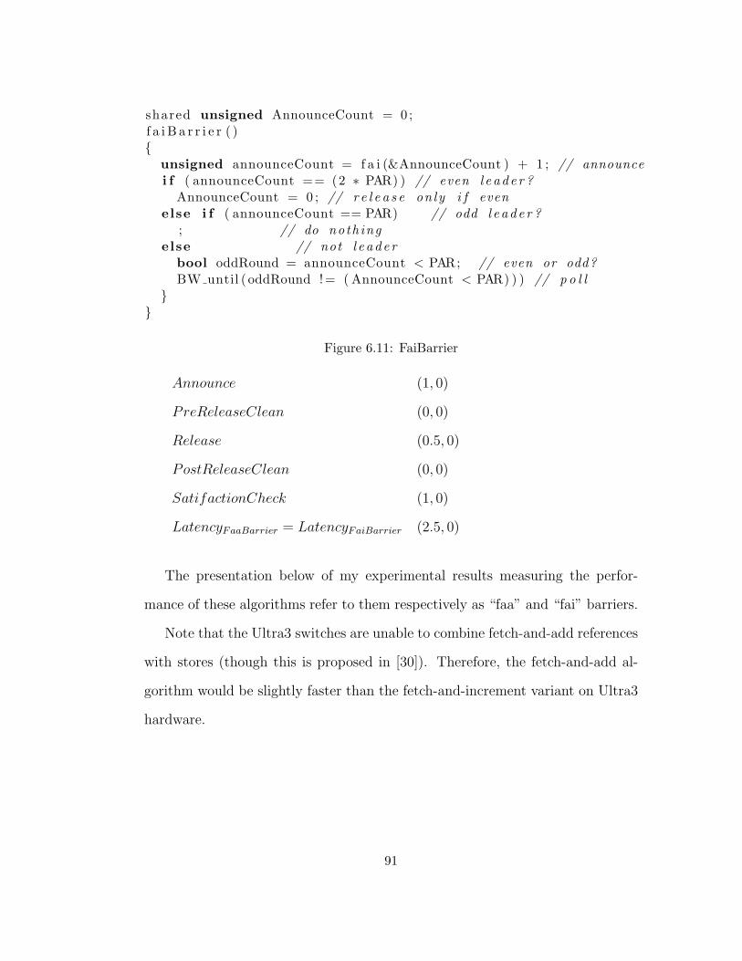
shared unsigned AnnounceCount = 0 ;f a i B a r r i e r ( ){
unsigned announceCount = f a i (&AnnounceCount ) + 1 ; // announcei f ( announceCount == (2 ∗ PAR) ) // even l eade r ?
AnnounceCount = 0 ; // r e l e a s e on ly i f evenelse i f ( announceCount == PAR) // odd l e ade r ?
; // do noth ingelse // not l e ade r
bool oddRound = announceCount < PAR; // even or odd?BW until ( oddRound != ( AnnounceCount < PAR) ) ) // p o l l
}}
Figure 6.11: FaiBarrier
Announce (1, 0)
PreReleaseClean (0, 0)
Release (0.5, 0)
PostReleaseClean (0, 0)
SatifactionCheck (1, 0)
LatencyFaaBarrier = LatencyFaiBarrier (2.5, 0)
The presentation below of my experimental results measuring the perfor-
mance of these algorithms refer to them respectively as “faa” and “fai” barriers.
Note that the Ultra3 switches are unable to combine fetch-and-add references
with stores (though this is proposed in [30]). Therefore, the fetch-and-add al-
gorithm would be slightly faster than the fetch-and-increment variant on Ultra3
hardware.
91
6.8 Eliminating Release Latency
Fully half of the memory accesses required for symBarrier are due to its release
latency. Dimitrovsky’s single variable algorithm reduces this by a factor of two
by resetting AnnounceCount only on even numbered super-steps. If the count
variable was an integer with infinite range, then an algorithm could be con-
structed that never reset the count variable since the superstep number is equal
to bcount/PARc and the number of processes that have completed the current
superstep is equal to count (mod PAR). Although fixed-width integer vari-
ables have a limited range and do overflow, correct computation of the barrier
count will occur providing 2wordsize is a multiple of PAR.
Pow2Barrier, presented in Figure 6.12, exploits this effect and has the op-
timal latency of (2,0). This latency is optimal for barrier synchronization using
fetch-and-add since all non-leader processes executing a barrier must issue at
least one memory reference to announce its completion of a superstep, and at
least one additional operation to determine that the barrier is satisfied.
6.8.1 Modeled Latency of Pow2Barrier
The shared memory counts and modeled latency of pow2Barrier is:
Announce (1, 0)
SatisfactionCheck (1, 0)
LatencyPow2Barrier (2, 0)
Pow2Barrier2 (see Figure 6.13) is a variant of pow2Barrier that utilizes only
the least significant bit of the computed super-step count to determine if the
92

shared unsigned AnnounceCount = 1 ;
pow2Barrier ( ) // ONLY USE IF 2ˆWORDSIZE i s a MULTIPLE of PAR{
announceCount = f a i (&AnnounceCount ) ;i f ( announceCount % PAR == 0) // I s a t i s f i e d b a r r i e r
return ;else {
super s t ep = announceCount / PAR;BW until ( ( super s t ep != AnnounceCount / PAR) )
}}
Figure 6.12: Pow2Barrier
pow2Barrier2 ( ) // a l t e r n a t e power−of−two b a r r i e r{
announceCount = f a i (&AnnounceCount ) ;i f ( announceCount % PAR == 0) // I s a t i s f i e d b a r r i e r
return ;else
super s t ep = announceCount / PAR;BW until ( ( ( super s t ep % 2) != ( ( AnnounceCount / PAR) % 2) ;
}
Figure 6.13: Pow2Barrier2
barrier is satisfied. This algorithm requires the same number of shared accesses
as pow2Barrier and is somewhat more complicated; I present this algorithm
because it illustrates a technique utilized by more complicated algorithms below.
Unfortunately, both power-of-two barriers will deadlock on overflow if PAR
is not a factor of MAXINT +1. LazyCleanFaiBarrier prevents overflows by re-
setting AnnounceCount infrequently, raising the amortized critical path latency
slightly to only 2 + PAR/(MAXINT + 1) = 2 + ε shared accesses:
93
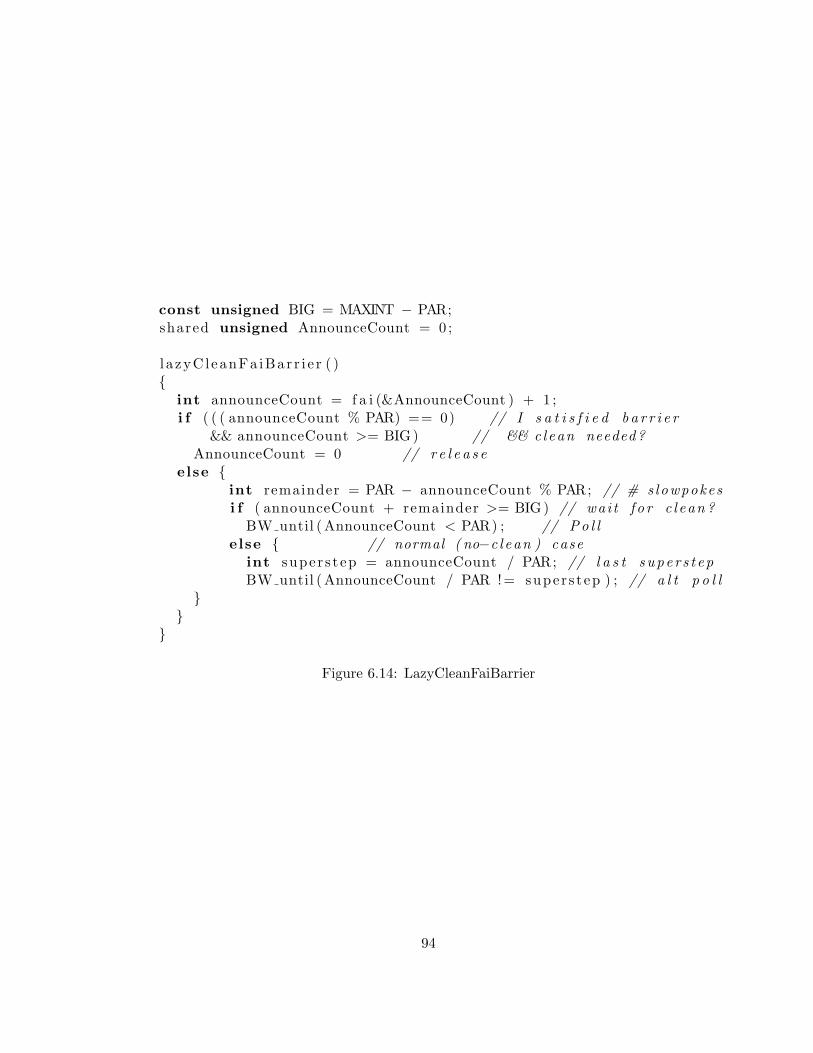
const unsigned BIG = MAXINT − PAR;shared unsigned AnnounceCount = 0 ;
l azyCleanFa iBar r i e r ( ){
int announceCount = f a i (&AnnounceCount ) + 1 ;i f ( ( ( announceCount % PAR) == 0) // I s a t i s f i e d b a r r i e r
&& announceCount >= BIG) // && clean needed?AnnounceCount = 0 // r e l e a s e
else {int remainder = PAR − announceCount % PAR; // # s lowpokesi f ( announceCount + remainder >= BIG) // wai t f o r c l ean ?
BW until (AnnounceCount < PAR) ; // Po l lelse { // normal ( no−c l ean ) case
int super s t ep = announceCount / PAR; // l a s t supe r s t epBW until (AnnounceCount / PAR != super s tep ) ; // a l t p o l l
}}
}
Figure 6.14: LazyCleanFaiBarrier
94

6.8.2 Modeled latency of lazyCleanFaiBarrier
The shared memory counts and modeled latency of lazyCleanFaiBarrier is:
Announce (1, 0)
Release (PAR/MAX UNSIGNED, 0) = (ε, 0)
SatifactionCheck (1, 0)
LatencyLazyCleanFaiBarrier (2 + ε, 0)
When cleaning is required, no processes executing lazyCleanFaiBarrier may
continue until after the leader’s release access has reset the announce count. The
lazy-clean fetch-and-add barrier presented below eliminates this dependency. In
these algorithms, non-leader processes’ detection of barrier satisfaction and the
leaders’ cleaning of announce count are decoupled. As a result, the cleaning can
be reclassified as a PostRleaseClean access, further reducing latency in shared
accesses to the optimal value of (2, 0).
Like pow2Barrier2, LazyCleanFaaBarrier is a self-service algorithm that ex-
ploits the alternation of even and odd supersteps to atomically reset the barrier
count in a manner that does not disturb the computation of barrier satisfaction.
LazyCleanFaaBarrier utilizes a single non-unit fetch-and-add to atomically sub-
tract a multiple of 2 * par from the value of AnnounceCount. This subtraction
neither affects the value of oddSuperStep(AnnounceCount, par) nor the value of
AnnounceCount mod PAR, which allows the the clean operation to be executed
post release.
95
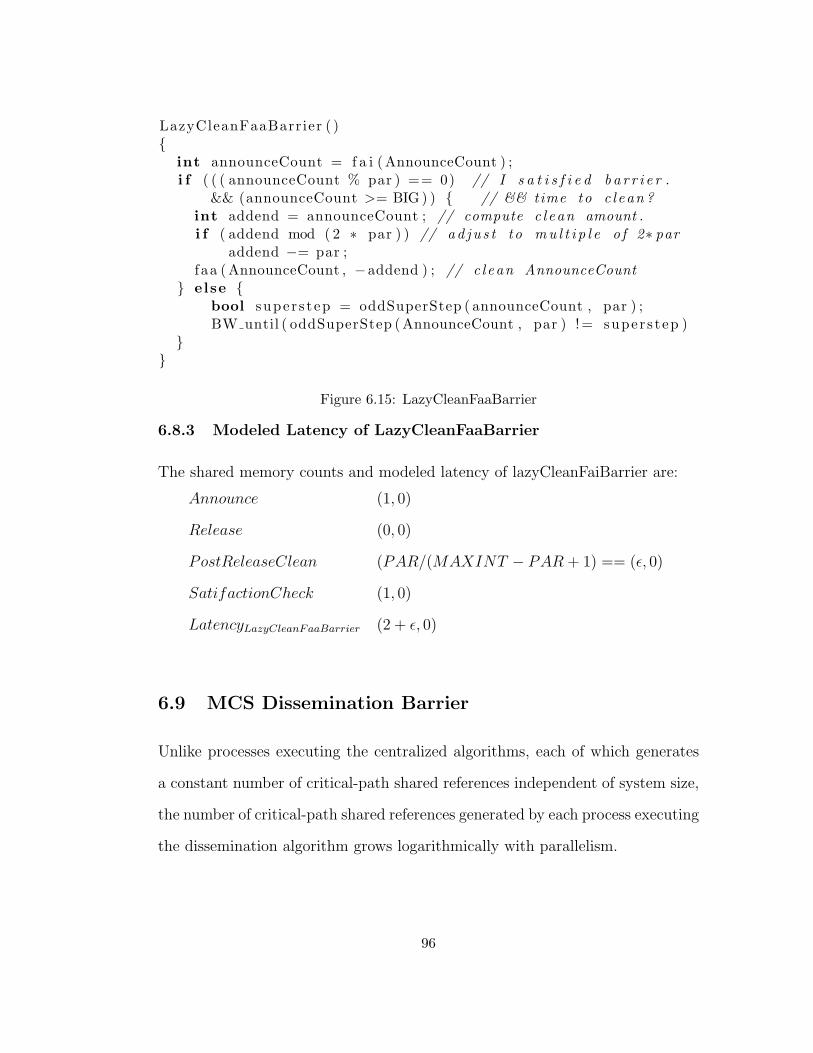
LazyCleanFaaBarrier ( ){
int announceCount = f a i (AnnounceCount ) ;i f ( ( ( announceCount % par ) == 0) // I s a t i s f i e d b a r r i e r .
&& (announceCount >= BIG ) ) { // && time to c l ean ?int addend = announceCount ; // compute c l ean amount .i f ( addend mod ( 2 ∗ par ) ) // ad ju s t to mu l t i p l e o f 2∗ par
addend −= par ;faa (AnnounceCount , −addend ) ; // c l ean AnnounceCount
} else {bool super s t ep = oddSuperStep ( announceCount , par ) ;BW until ( oddSuperStep (AnnounceCount , par ) != super s tep )
}}
Figure 6.15: LazyCleanFaaBarrier
6.8.3 Modeled Latency of LazyCleanFaaBarrier
The shared memory counts and modeled latency of lazyCleanFaiBarrier are:
Announce (1, 0)
Release (0, 0)
PostReleaseClean (PAR/(MAXINT − PAR + 1) == (ε, 0)
SatifactionCheck (1, 0)
LatencyLazyCleanFaaBarrier (2 + ε, 0)
6.9 MCS Dissemination Barrier
Unlike processes executing the centralized algorithms, each of which generates
a constant number of critical-path shared references independent of system size,
the number of critical-path shared references generated by each process executing
the dissemination algorithm grows logarithmically with parallelism.
96
Recall that the dissemination algorithm executes in a sequence of rounds, each
of which generates a single non-hot spot shared access. Therefore the latency in
shared accesses of this algorithm on a PRAM is (0, log2PAR).
The dissemination algorithm has no clean insertion point where processes
can execute code that overlaps supersteps without delaying others, making it
incompatible with Gupta’s fuzzyWork technique for exploiting barrier latency.
An alternative distributed tree algorithm that supports fuzzy work is presented
in [39].
6.10 Experimental Results
I again use super-step latency as a metric for execution speed of a simulated BSP
computation. Three synthetic workloads are considered: the first Wi measures
barrier latency by executing a sequence of super-steps containing no computation
(in this case, super-step latency equals barrier latency). The other two workloads
Wu and Wm (described below) measure super-step latency for workloads that
generate sequences of shared accesses during each super-step.
This model for barrier latency counts only shared references executed along
the critical path from the last process’ termination of superstep i and all pro-
cesses commencing superstep i+1. The latency of synchronization (measured as
superstep latency with no work performed between synchronizations), normal-
ized by the average memory access latency for workload Wi is plotted in Figure
6.16.
In order to highlight the contribution of the shared memory system, synchro-
97
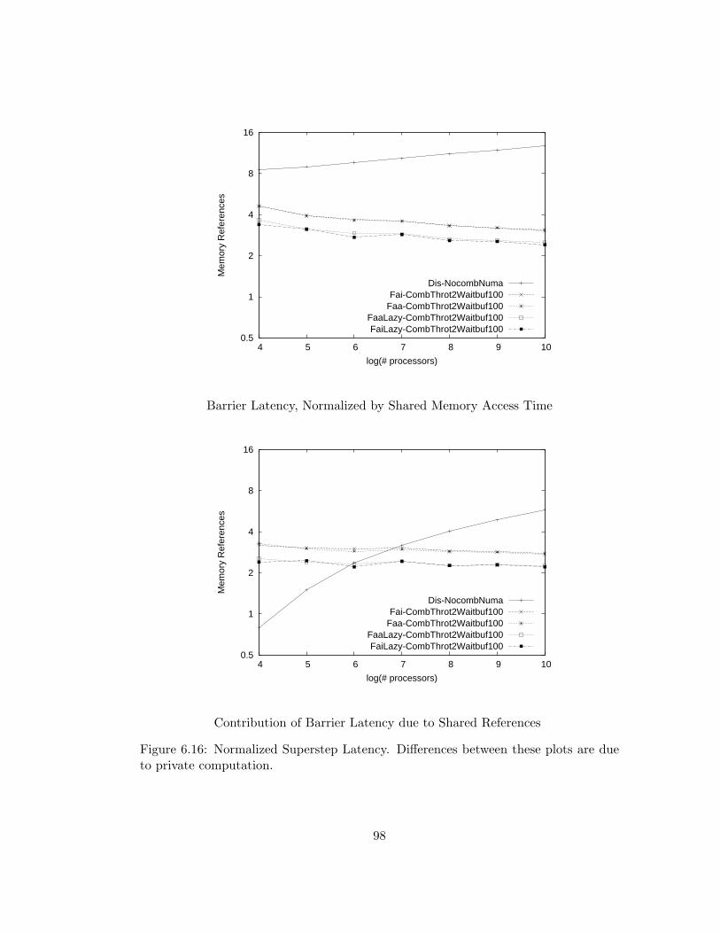
0.5
1
2
4
8
16
4 5 6 7 8 9 10
Mem
ory
Ref
eren
ces
log(# processors)
Dis-NocombNumaFai-CombThrot2Waitbuf100
Faa-CombThrot2Waitbuf100FaaLazy-CombThrot2Waitbuf100FaiLazy-CombThrot2Waitbuf100
Barrier Latency, Normalized by Shared Memory Access Time
0.5
1
2
4
8
16
4 5 6 7 8 9 10
Mem
ory
Ref
eren
ces
log(# processors)
Dis-NocombNumaFai-CombThrot2Waitbuf100
Faa-CombThrot2Waitbuf100FaaLazy-CombThrot2Waitbuf100FaiLazy-CombThrot2Waitbuf100
Contribution of Barrier Latency due to Shared References
Figure 6.16: Normalized Superstep Latency. Differences between these plots are dueto private computation.
98

nization latency, measured on a simulated (idealized) PRAM with single-cycle
shared memory is subtracted from synchronization latency prior to normaliza-
tion for the lower chart in Figure 6.16. Differences between the upper and lower
charts, which indicate the cost of computation on a FAA PRAM, diminish with
system size for the centralized algorithms due to the increasing latency of hot
spot accesses, which are responsible for most of the cost of synchronization.
However, private computation remains a significant component of the latency
of the distributed algorithm when executed on large systems due to its lower
memory latency and greater number of interlocked shared accesses.
For larger systems, the number of shared references on the critical paths of
the dissemination algorithm is logarithmic in the number of shared accesses; for
the centralized algorithms it is a constant between two and three. However, the
cost of the increased number of accesses incurred by the dissemination algorithm
is mitigated by its ability to communicate a value from processor one to another
processor in a single network traversal when executed on a NUMA system, as
is illustrated by the “Dis-NocombNuma” plot of the lower chart in Figure 6.16.
This plot indicates that, for ten stage systems, the contribution of the ten in-
terlocked memory references generated at each synchronization is equivalent to
the latency of five (round trip) shared memory accesses. However, the corre-
sponding plot in the upper chart indicates that the latency of synchronization
is approximately equal to ten times memory reference latency. Therefore, the
latency private computation is roughly equivalent to memory reference latency
for this algorithm.
Recall that the “fai” and “fai” barriers have a shared-memory reference cost
99

of approximately 2.5 memory references, and their lazy-clean variants (which
amortize the cost of cleaning over multiple supersteps) have a cost of approx-
imately 2. Measured latency for these algorithms, indicated in Figure 6.16 is
slightly greater than these values.
Barrier latency, in cycles, for workload Wi is plotted in Figure 6.17 for
the improved decoupled (CombThrot2Waitbuf100) and coupled (ACombFirst-
Throt1Waitbuf100) architectures. When executed on the decoupled architec-
ture, “lazy clean” barriers have the lowest superstep latency, which is about
10% lower than than the latency of the dissemination barrier. The latency of
barrier algorithms that clean frequently is about 30% greater than the latency
of the “lazy-clean” algorithms that amortize cleaning over multiple supersteps.
However, when executed on a system with coupled adaptive switches, on which
hot spot latency is roughly equivalent to uniform, the latency of dissemination
barriers is four to five times the latency of the centralized algorithms. Once
again, the algorithms that amortize cleaning over multiple supersteps have the
shortest barrier latency.
6.10.1 Barrier synchronization between simulated work phases
In the experiment described above, no computation was performed between bar-
rier executions. In practice, barrier synchronization is used to coordinate compu-
tation among cooperating processes, presumably issuing shared memory accesses
between barriers3.
Figures 6.18 and 6.19 indicate superstep latency, measured in system clock
3Otherwise there would be no need for synchronization.
100
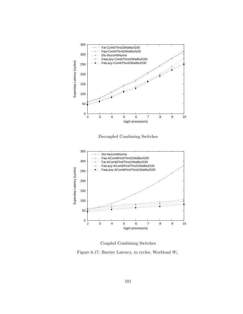
0
50
100
150
200
250
300
350
2 3 4 5 6 7 8 9 10
Sup
erst
ep L
aten
cy (
cycl
es)
log(# processors)
Fai-CombThrot2Waitbuf100Faa-CombThrot2Waitbuf100Dis-NocombNumaFaaLazy-CombThrot2Waitbuf100FaiLazy-CombThrot2Waitbuf100
Decoupled Combining Switches
0
50
100
150
200
250
300
350
2 3 4 5 6 7 8 9 10
Sup
erst
ep L
aten
cy (
cycl
es)
log(# processors)
Dis-NocombNumaFaa-ACombFirstThrot1Waitbuf100Fai-ACombFirstThrot1Waitbuf100FaiLazy-ACombFirstThrot1Waitbuf100FaaLazy-ACombFirstThrot1Waitbuf100
Coupled Combining Switches
Figure 6.17: Barrier Latency, in cycles, Workload Wi
101

cycles, for experiments that generate synthetic workloads between barriers. Two
sets of experiments with differing workloads are conducted: Uniform workload
Wu issues thirty shared memory references during each super-step. For the mixed
workload experiment Wm, half of the processors issue fifteen shared references
between each super-step, and the other half issue thirty. The sequence generated
by each processor is interleaved among MMs in order not to generate hot-spots
beyond those required by the coordination algorithm being evaluated. These
additional accesses are not combinable.
6.10.2 Experimental Results for Uniform and Mixed Simulated Work-
loads
Both the Wu and Wm synthetic workloads overshadow the latency of synchro-
nizations, narrowing the latency differences between various algorithms and ar-
chitectures. Whereas we observed latencies differing by a factor of five when
superstep bodies were empty, the largest differences are only 25% for these more
realistic workloads. Superstep latencies for workloads Wu and Wm are plotted
in figures 6.18 and 6.19, respectively and are summarized in Table 6.1.
Comparative performance of Centralized Algorithms
As anticipated by the analysis presented in Section 6.3, superstep latency is
lower for both Wm and Wu synchronized by the centralized lazy-clean algorithms
than for the centralized algorithms that clean frequently. However, the measured
difference is generally small, never more than 5% for Wu and 10% for Wm. There
is no significant difference between the latency of supersteps synchronized using
102
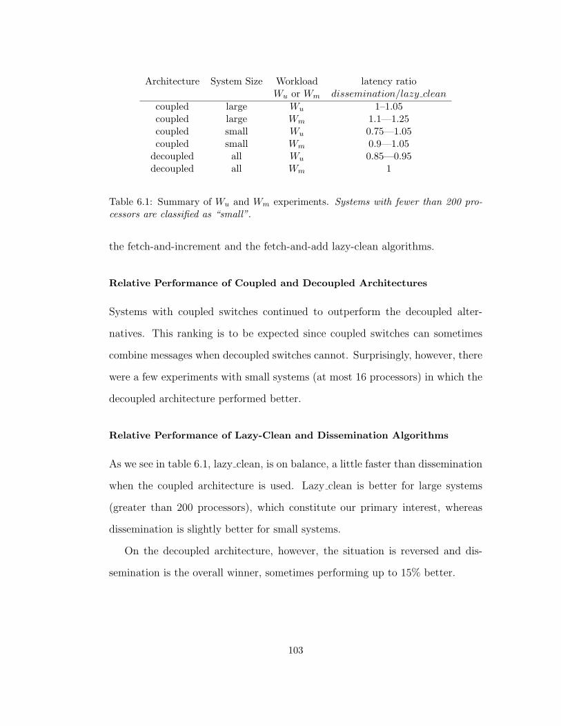
Architecture System Size Workload latency ratioWu or Wm dissemination/lazy clean
coupled large Wu 1–1.05coupled large Wm 1.1—1.25coupled small Wu 0.75—1.05coupled small Wm 0.9—1.05
decoupled all Wu 0.85—0.95decoupled all Wm 1
Table 6.1: Summary of Wu and Wm experiments. Systems with fewer than 200 pro-cessors are classified as “small”.
the fetch-and-increment and the fetch-and-add lazy-clean algorithms.
Relative Performance of Coupled and Decoupled Architectures
Systems with coupled switches continued to outperform the decoupled alter-
natives. This ranking is to be expected since coupled switches can sometimes
combine messages when decoupled switches cannot. Surprisingly, however, there
were a few experiments with small systems (at most 16 processors) in which the
decoupled architecture performed better.
Relative Performance of Lazy-Clean and Dissemination Algorithms
As we see in table 6.1, lazy clean, is on balance, a little faster than dissemination
when the coupled architecture is used. Lazy clean is better for large systems
(greater than 200 processors), which constitute our primary interest, whereas
dissemination is slightly better for small systems.
On the decoupled architecture, however, the situation is reversed and dis-
semination is the overall winner, sometimes performing up to 15% better.
103
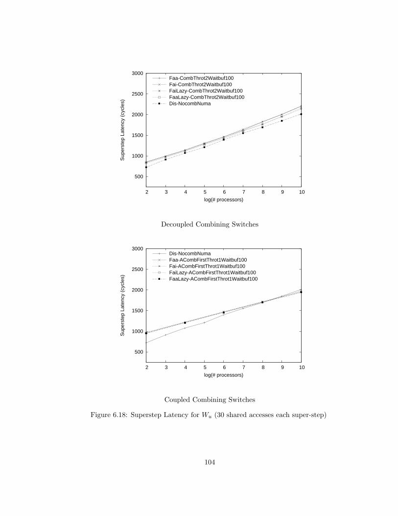
500
1000
1500
2000
2500
3000
2 3 4 5 6 7 8 9 10
Sup
erst
ep L
aten
cy (
cycl
es)
log(# processors)
Faa-CombThrot2Waitbuf100Fai-CombThrot2Waitbuf100FaiLazy-CombThrot2Waitbuf100FaaLazy-CombThrot2Waitbuf100Dis-NocombNuma
Decoupled Combining Switches
500
1000
1500
2000
2500
3000
2 3 4 5 6 7 8 9 10
Sup
erst
ep L
aten
cy (
cycl
es)
log(# processors)
Dis-NocombNumaFaa-ACombFirstThrot1Waitbuf100Fai-ACombFirstThrot1Waitbuf100FaiLazy-ACombFirstThrot1Waitbuf100FaaLazy-ACombFirstThrot1Waitbuf100
Coupled Combining Switches
Figure 6.18: Superstep Latency for Wu (30 shared accesses each super-step)
104
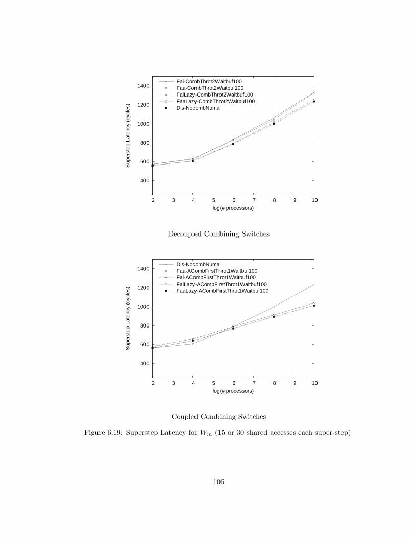
400
600
800
1000
1200
1400
2 3 4 5 6 7 8 9 10
Sup
erst
ep L
aten
cy (
cycl
es)
log(# processors)
Fai-CombThrot2Waitbuf100Faa-CombThrot2Waitbuf100FaiLazy-CombThrot2Waitbuf100FaaLazy-CombThrot2Waitbuf100Dis-NocombNuma
Decoupled Combining Switches
400
600
800
1000
1200
1400
2 3 4 5 6 7 8 9 10
Sup
erst
ep L
aten
cy (
cycl
es)
log(# processors)
Dis-NocombNumaFaa-ACombFirstThrot1Waitbuf100Fai-ACombFirstThrot1Waitbuf100FaiLazy-ACombFirstThrot1Waitbuf100FaaLazy-ACombFirstThrot1Waitbuf100
Coupled Combining Switches
Figure 6.19: Superstep Latency for Wm (15 or 30 shared accesses each super-step)
105
6.11 Evaluation of Limitation of Poll Frequency
As described in 2.1, limiting the polling frequency for hot spot busy-waiting has
been widely utilized on systems without combining as a mechanism to reduce
hot spot contention and thereby the latency of synchronization. To evaluate
this technique on systems that implement hardware combining, I conducted a
small simulation study that modulates the frequency of busy-wait polling of hot
spot variables using the exponential back-off algorithm presented in Figure 2.1.
Results from this study, presented in Appendix D, indicate that reducing the
frequency of busy-wait polling does not reduce super-step latency.
6.12 Chapter Conclusion
The analytical framework presented in this chapter appears to correctly model
synchronization latency for centralized barriers when evaluated with experiment
Wi’s empty simulated workloads. However, Wi does not model a system of prac-
tical importance. When more realistic workloads (Wu and Wm) are evaluated,
the latency differences between these algorithms are overshadowed by the much
larger execution time of the non-empty workloads investigated, indicating that:
• Algorithms to enforce barrier coordination using fetch-and-increment have
performance similar to those that require fetch-and-add with unrestricted
addends.
• Only a small benefit (0–10% latency improvement) is realized from the op-
timizations described in this chapter that minimize the number of accesses
106
generated by centralized barrier algorithms.
107
Chapter 7
Reader-Writer Coordination
In this chapter, I evaluate the scalability of several busy-waiting algorithms
that enforce writer-priority reader-writer coordination on MIMD-shared-memory
computers. All of these algorithms generate hot-spot memory traffic and there-
fore benefit from the availability of combining. However, unlike the NYU al-
gorithms of [2] and [12], the Algorithms of Mellor-Crummey and Scott only
generate a constant number of hot-spot accesses each time a lock is requested
since they do not poll hot spot variables.
This chapter is organized as follows: I begin by describing the reader-writer
coordination protocol and the algorithms evaluated. I present two centralized
algorithms: The first, which requires fetch-and-add, is a variant of the algorithm
published by Gottlieb et al [2]. The second algorithm, described in Freuden-
thal and Gottlieb [12], uses a restricted form of fetch-and-add with only unit
addends. In this chapter, I also introduce the notion of immediate coordination,
which reduces the number of accesses required to acquire a non-contended lock.
108
I also present an overview of the local-spin MCS algorithm. Finally, a evaluation
framework utilizing micro-benchmarks is presented, and used to produce simula-
tion results over a wide range of system sizes. These experiments modeled both
on non-combining and combining networks. The algorithms are evaluated using
the same two adaptive combining switch designs that were used in the barrier
coordination experiments of the preceding chapter.
7.1 Reader-Writer Coordination
The readers and writers synchronization protocol, introduced in [40], coordinates
access by two classes of processes to a protected resource. Processes in the first
class, writers, require exclusive access. In contrast, processes in the second
class, readers, may share the resource with other readers. Additional fairness
conditions limiting the time a process may need to wait for access can also be
imposed.
The most likely cause of unbounded waiting is that readers are permitted to
begin while other readers are active and thus a continual stream of readers may
starve all writers. The algorithms evaluated eliminate this possibility by the
standard technique of giving writers priority, which naturally does not prevent
writers from starving readers. In addition, the centralized algorithms evaluated
in my research utilize an unfair semaphore that permits writers to starve other
writers.
109
7.2 Centralized Algorithms for Readers and Writers
Many algorithms for readers/writers coordination have appeared. Courtois and
Heyman [40] introduced the problem and presented a solution that serializes en-
try of readers as well as writers. A fetch-and-add based algorithm is presented
in [2] that eliminates serialization of readers in the absence of writers. These
bottleneck-free [2] algorithms, however, make essential use of non-unit addends:
Readers manipulate a shared variable using fetch-and-add (FAA) with unit ad-
dends (essentially P/V on a counting semaphore). Writers manipulate these
same variables but use addends of positive or negative K, for a large constant
K.
In [12], we introduced a bottleneck-free algorithm that stores the counts
of readers and writers in distinct variables and require only unit addends for
fetch-and-add operations. Fetch-and-add operations with unit addends are called
fetch-and-increment (FAI) and fetch-and-decrement (FAD). In this chapter, I
refer to this as the fetch-and-increment algorithm for readers-writer coordination.
Both the fetch-and-add and fetch-and-increment algorithms give writers pri-
ority, and are bottleneck-free in the absence of contention. More formally, these
bottleneck-free algorithms have the following characteristics:
1. Readers exclude writers.
2. Writers exclude other writers.
3. Deadlock and livelock are impossible.
4. Readers are not serialized, i.e. their execution is bottleneck-free.
110
5. Readers can not starve writers.
The first three characteristic items are standard safety and liveness proper-
ties for reader-writer coordination, and the fifth is a fairness property common
in implementations that enforce writer priority. The fourth characteristic of
these bottleneck-free algorithms is somewhat unusual and formally defines the
bottleneck-free property introduced in [2]. Assume that no writers are present
during a given time interval. Then there exists a (small) constant C such that
any requesting reader will be granted the lock after executing at most C instruc-
tions. Note that C does not depend on the number of requesters. To illustrate
the strength of this statement, let us assume the CRCW PRAM model of com-
putation. Then, in the absence of writers, any number of requesting readers
will all be granted the reader lock within C cycles. That is, the execution is
bottleneck-free. To the best of our knowledge only the algorithm of [2], which
requires non-unit addends, and the fetch-and-increment algorithm of [12] have
this desirable property. Proofs of correctness for the NYU algorithms appear
in [50] and [12] respectively. The latter is duplicated in Appendix A of this
dissertation.
7.3 Bottleneck-Free Centralized Algorithms
My research investigates the performance of two variants of the bottleneck-free
algorithms introduced in [2] and [12]. All of of these algorithms utilize a cen-
tralized data structure that implements two counters, one for readers, the other
for writers. The algorithm proposed by Gottlieb, Lubachevsky, and Rudolph
111

in [2] stores these two counters in a single memory word. Their algorithm makes
essential use of a single fetch-and-add with non-unit addend to atomically adjust
and read the values of both counters. In [12], we presented an algorithm that
stores the two counts in separate integers. This algorithm only requires fetch-
and-add addends of +/- 1, and therefore is suitable for architectures that support
fetch-and-increment/decrement but not fetch-and-add with arbitrary addends.
7.4 Uncontended Lock Performance and Immediate Co-
ordination
The original bottleneck-free algorithms for writer priority readers-writers coor-
dination described in [2] and [12] have behavior I categorize as delayed: Like the
test-and-test-and-set protocols of Rudolph and Segall [1] that reduce memory
traffic for cache-coherent systems and also prevent live-lock, delayed protocols
do not modify state variables until observing the lock as available. This probe to
observe initial lock status prevents a transient form of live-lock where the grant-
ing of a writer writer lock is delayed by a stream of new reader lock requests.
Since the set of reader processes is bounded (and each of the other readers will
eventually decrement the reader count back to zero), this condition does not
result in livelock since, after the initial decrement, immediate algorithms revert
to the delayed behavior when contention is detected.
Resources expended in the execution of coordination algorithms are not avail-
able for productive work. In the absence of contention, references to shared mem-
ory typically dominate execution time of these algorithms, making algorithms
112
that generate fewer references preferable.
In the absence of contention, the cost of synchronization is dominated by
shared references. Algorithms to enforce readers-and-writers coordination typ-
ically generate a greater number of shared memory references than algorithms
that enforce mutual exclusion. Readers-and-writers coordination only yields
benefits over mutual exclusion when sufficient reader parallelism is exploited to
dominate this increased cost. Figure 7.1 illustrates the relationships between
immediate and delayed protocols for counting semaphores.
Clearly any algorithm to enforce locking protocols must issue at least one
memory reference each time a lock is granted or released. For example, the
test-and-set algorithm for mutual exclusion generates exactly this number of
references. The delayed FAA algorithms to enforce readers and writers coordi-
nation and semaphores presented in [2] require two shared references to grant
an uncontended lock, and one additional shared reference to release the lock.
Delayed protocols have both benefit and cost: a delayed process requesting
a lock first inspects lock state before making its request and therefore reduces
interference with the progress of another process simultaneously requesting ac-
cess. This inspection imposes a communication overhead of one additional shared
memory reference prior to requesting a lock. This extra memory load yields no
benefit in the absence of contention.
I recognized that these algorithms can be coded in a more assertive style that
I characterize as immediate. As their name implies, immediate implementations
of coordination algorithms do not initially check if a lock is available prior to
requesting entry. In the absence of contention, immediate algorithms generate
113
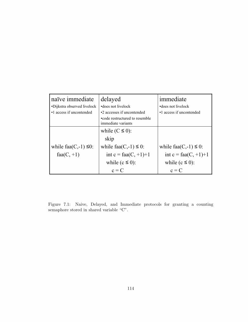
while faa(C,-1) ≤ 0:int c = faa(C, +1)+1while (c ≤ 0):
c = C
while (C ≤ 0):skip
while faa(C,-1) ≤ 0:int c = faa(C, +1)+1while (c ≤ 0):
c = C
while faa(C,-1) ≤0:faa(C, +1)
immediate•does not livelock•1 access if uncontended
delayed•does not livelock•2 accesses if uncontended•code restructured to resemble immediate variants
naïve immediate•Dijkstra observed livelock•1 access if uncontended
Figure 7.1: Naive, Delayed, and Immediate protocols for granting a countingsemaphore stored in shared variable “C”.
114

fewer memory references than their delayed counterparts. In particular, in the
absence of contention, the immediate fetch-and-add algorithm for readers-writers
coordination presented below generates only one shared reference to grant or
release either class of lock. One additional memory reference is generated by my
immediate fetch-and-increment algorithm when granting an uncontended lock.
Interaction of immediate synchronization and coherent caches: The advan-
tage of immediate algorithms comes from a reduction in shared memory accesses
when a lock is not contended. If the lock is contended, a immediate writer pro-
cess requesting a lock that is unavailable will increment its count, determine that
the lock is unavailable, decrement it, and then busy-wait until the lock is next
available. During the interval i between the initial increment and decrement,
no other process can be granted the lock. The duration of this interval is the
latency of a small number of shared accesses.
Loads are combinable on Ultra3, and shared memory accesses on an Ultra3
are not cached. Therefore, the premature fetch-and-add does not dramatically
change memory latency to the hot spot variable. However, on cache coher-
ent systems, a fetch-and-add operation typically cause invalidations of cached
copies of the target variables. If a large number of other processes are actively
busy-waiting during interval i, then memory access latency may temporarily be
dramatically increased due to memory contention from cache invalidation and
reloading. Therefore, on cache-coherent systems, this increased memory latency
can reduce system performance, both by substantially increasing the length of
interval i and by delaying unrelated computation.
115
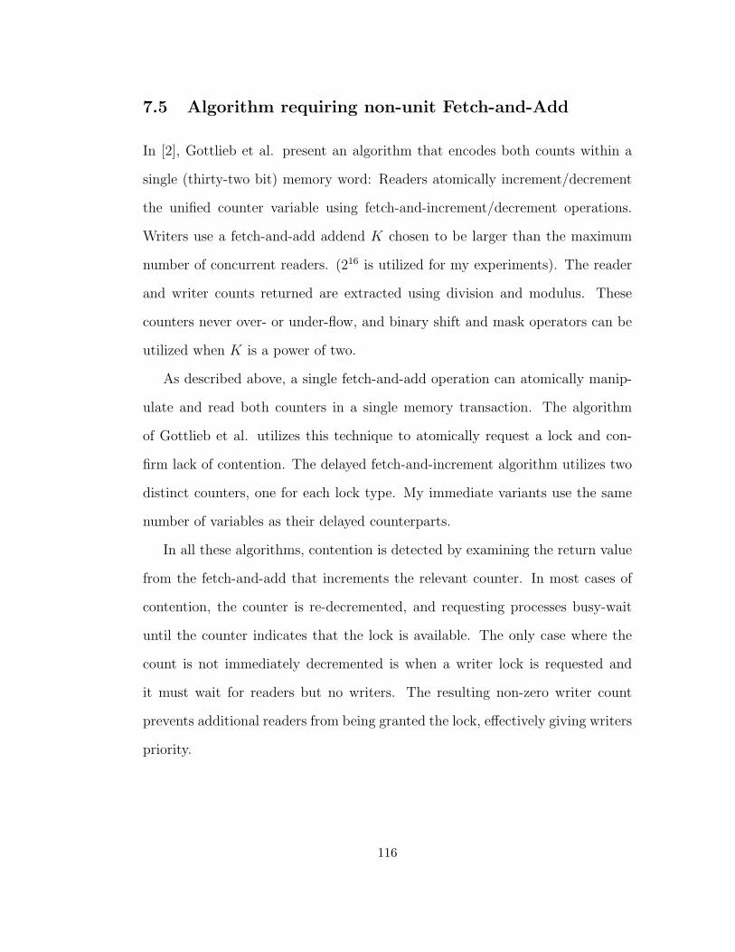
7.5 Algorithm requiring non-unit Fetch-and-Add
In [2], Gottlieb et al. present an algorithm that encodes both counts within a
single (thirty-two bit) memory word: Readers atomically increment/decrement
the unified counter variable using fetch-and-increment/decrement operations.
Writers use a fetch-and-add addend K chosen to be larger than the maximum
number of concurrent readers. (216 is utilized for my experiments). The reader
and writer counts returned are extracted using division and modulus. These
counters never over- or under-flow, and binary shift and mask operators can be
utilized when K is a power of two.
As described above, a single fetch-and-add operation can atomically manip-
ulate and read both counters in a single memory transaction. The algorithm
of Gottlieb et al. utilizes this technique to atomically request a lock and con-
firm lack of contention. The delayed fetch-and-increment algorithm utilizes two
distinct counters, one for each lock type. My immediate variants use the same
number of variables as their delayed counterparts.
In all these algorithms, contention is detected by examining the return value
from the fetch-and-add that increments the relevant counter. In most cases of
contention, the counter is re-decremented, and requesting processes busy-wait
until the counter indicates that the lock is available. The only case where the
count is not immediately decremented is when a writer lock is requested and
it must wait for readers but no writers. The resulting non-zero writer count
prevents additional readers from being granted the lock, effectively giving writers
priority.
116

When examining the utility of atomic-add for semaphores, Dijkstra observed
that naive algorithms that includes a decrement in their polling loops are subject
to live lock [8]. Gottlieb et al. introduced an alternative polling technique that
eliminated this live-lock problem by using a protocol called test-decrement-retest
and test-increment-retest. These protocols protect fetch-and-adds that request
a resource within a busy-waiting loop with an additional fetch indicating that
the resource is (transiently) available [2].
Figure 7.2 contains an implementation of both the immediate and delayed
reader-writer locks requiring fetch-and-add with non-unit addends.
7.6 Fetch-and-Increment Algorithm
As described above, the fetch-and-increment algorithm, presented in [12] and re-
produced in Figure 7.3, utilizes separate counters for readers and writers. This
algorithm has a structure that resembles the two-way load-store mutex of Pe-
terson [42], with counters for each class of process replacing that algorithm’s
boolean flags. As with the fetch-and-add based algorithm, the performance of
both immediate and delayed variants is investigated below. The correctness of
this algorithm is demonstrated in the appendix of [12]; this proof is reproduced
in Appendix A of this dissertation.
Note that the fetch-and-increment algorithms generate hot-spot traffic to
two distinct shared variables ReaderCount and WriterCount. These variables
may be co-resident in the same memory unit. To examine the impact of this
potential co-residency on algorithm performance, plots in this chapter include
117
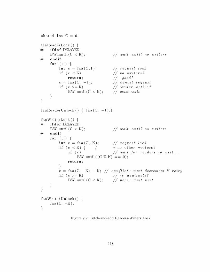
shared int C = 0;
faaReaderLock ( ) {# ifde f DELAYED
BW until (C < K) ; // wai t u n t i l no wr i t e r s# endif
for ( ; ; ) {int c = faa (C, 1 ) ; // r e que s t l o c ki f ( c < K) // no wr i t e r s ?
return ; // good !c = faa (C, −1) ; // cance l r e q eu s ti f ( c >= K) // wr i t e r a c t i v e ?
BW until (C < K) ; // must wai t}
}
faaReaderUnlock ( ) { f aa (C, −1) ;}
faaWriterLock ( ) {# ifde f DELAYED
BW until (C < K) ; // wai t u n t i l no wr i t e r s# endif
for ( ; ; ) {int c = faa (C, K) ; // r e que s t l o c ki f ( c < K) { / ∗ no other w r i t e r s ?
i f ( c ) // wai t f o r readers to e x i t . . .BW until ( (C % K) == 0);
return ;}c = faa (C, −K) − K; // c o n f l i c t : must decrement & re t r yi f ( c >= K) // i s a v a i l a b l e ?
BW until (C < K) ; // nope ; must wai t}
}
faaWriterUnlock ( ) {f aa (C, −K) ;
}
Figure 7.2: Fetch-and-add Readers-Writers Lock
118
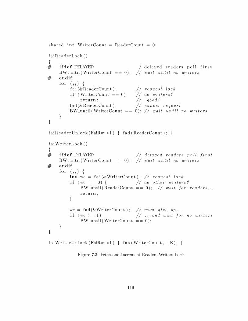
shared int WriterCount = ReaderCount = 0 ;
fa iReaderLock ( ){# ifde f DELAYED / delayed reade r s p o l l f i r s t
BW until ( WriterCount == 0) ; // wai t u n t i l no w r i t e r s# endif
for ( ; ; ) {f a i (&ReaderCount ) ; // r e que s t l o c ki f ( WriterCount == 0) // no wr i t e r s ?
return ; // good !fad(&ReaderCount ) ; // cance l r e q eu s tBW until ( WriterCount == 0) ; // wai t u n t i l no wr i t e r s
}}
fa iReaderUnlock (FaiRw ∗ l ) { fad ( ReaderCount ) ; }
f a iWri te rLock ( ){# ifde f DELAYED // de layed readers p o l l f i r s t
BW until ( WriterCount == 0) ; // wai t u n t i l no w r i t e r s# endif
for ( ; ; ) {int wc = f a i (&WriterCount ) ; // r e que s t l o c ki f ( wc == 0) { // no o ther w r i t e r s ?
BW until ( ReaderCount == 0) ; // wai t f o r readers . . .return ;
}
wc = fad(&WriterCount ) ; // must g i v e up . . .i f ( wc != 1 ) // . . . and wai t f o r no wr i t e r s
BW until ( WriterCount == 0);}
}
f a iWri terUnlock (FaiRw ∗ l ) { f aa ( WriterCount , −K) ; }
Figure 7.3: Fetch-and-Increment Readers-Writers Lock
119
two sets experimental runs using the FAI algorithm: The series denoted as
FAI have both variables resident in the same MM, the series denoted as FAI2
places these variables in two distinct MMs. Experimental results presented below
indicate that separating these hot-spot variables into distinct MMs yields a slight
performance improvement.
The centralized algorithms presented in Figure 7.2 utilize an improved tech-
nique to prevent starvation of writers by a continual stream of readers than the
writer-priority algorithm of Gottlieb et al. [2]. The latter utilized an additional
counter variable in a protocol that locks out readers when any writer is request-
ing the lock. This writer-priority protocol inserts several additional memory
references into the critical path of readers and writers.
7.7 Hybrid Algorithm of Mellor-Crummey and Scott
The writer-priority readers-writers algorithm of Mellor-Crummey and Scott [26]
is a hybrid of centralized and distributed approaches. Central state variables,
manipulated with fetch-and-φ operations, are used to count the number and type
of lock granted at any time. In addition, the centralized data structure includes
heads for two serial-access, linked list queues for control structures, containing
respectively, readers and writers awaiting entry.
Each process requesting entry inserts a control structure onto the queue cor-
responding to the lock it is requesting. Insertion onto these queues is achieved
by issuing atomic fetch-and-store operations to their respective heads (a single
hot-spot access corresponding to each lock request). These control structures,
120
each associated with a particular process, contain a busy-wait variable that in-
dicates when the lock is available. Each process P with an enqueued control
structure relies on another process (e.g. a writer releasing the latter) to notify
P that it can proceed.
These control structures are distributed throughout memory, thus eliminating
polling due to busy-waiting as a cause of hot-spot contention. As with the
other MCS data structure, the control structures are allocated from memory co-
located with their corresponding processes, thereby eliminating contention on
the shared-memory interconnection network due to busy-wait poling.
7.7.1 Scalability issues for the MCS Algorithm
In the absence of readers, a reader-writer lock simply enforces mutual exclu-
sion among the writers, and therefore parallel speedup is impossible. Mellor-
Crummey and Scott observed that contention-free acquisition is slower than
lock transfer to an already waiting potential writer. My experimental results
(below) confirm their observation.
This apparent speedup in the passing of a contended writer is not due to
parallelism of the critical section (which is impossible, since the definition of
reader-writer locks requires serialization), but instead due to pipelining of queue
insertion and lock passing. Recall that all processes requesting entry to the
writer section must manipulate a linked-list queue. If additional writers request
the lock while it is granted to another writer, these additional writer processes
will insert themselves onto the appropriate linked-list queue, readying themselves
for the passing of the writer lock.
121
Recall that local-spin algorithms do not generate congestion in the processor-
to-memory interconnection network due to busy-waiting since all processes are
busy-waiting on processor-local variables. Therefore the single memory access
(a write that notifies a waiting writer) required to pass a writer lock will not be
delayed by hot-spot congestion caused by busy-waiting.
Each process attempting to obtain a reader lock inserts itself on a linked list
queue using a fetch-and-store, which is parallelized by architectures that combine
fetch-and-stores. My experimental results, reported below, indicate that this op-
eration is a bottleneck on architectures that do not support combining. Note
that the queue-on-synch-bit primitive [24] is essentially an atomic linked-list in-
sertion, and implementations that parallelize it should yield similar performance
to my experiments utilizing combining fetch-and-store.
Once inserted into a linked list, each reader must be deleted, and linked list
access is inherently serial. However, in the absence of contention from writers,
the linked list is regularly cut into fragments by processes entering and exiting
the reader-section, limiting its length and preventing this list from growing suf-
ficiently to become a serial bottleneck for the range of system sizes I simulated.
7.8 Overview of Experimental Results
The results of my micro-benchmark experiments are presented in a series of
plots appearing at the end of this chapter. These simulations are conducted on
a variety of architectures with parameter settings that emulate several different
lock request patterns. In addition to providing gross comparisons of algorithm
122

performance, these experiments detect the sensitivity of these algorithms to the
performance of the underlying memory systems in the presence of hot-spot traffic.
My research indicates that none of the algorithms investigated is ideal for
all workloads. The MCS algorithm is superior when there is contention among
writers; the centralized algorithms are superior when there is much reader con-
currency and few writers. This difference is due to differences between idealized
behavior of readers and writers: In addition to having small constant costs,
an ideal reader lock, in the absence of contention, will yield speedups linear in
the number of processors. In contrast, an ideal writer lock will have no slow-
down as parallelism increases. My investigation indicates that when combining
is available, the centralized algorithms are superior for all cases except when
only writers request the lock.
7.9 Experimental Framework
The performance of locking primitives is unimportant when they are executed
infrequently, since they will not significantly contribute to execution time. My
experiments simulate the more interesting case of systems that frequently request
reader and writer locks. I ran two classes of experiments intended to detect
performance differences between reader-writer algorithms.
Experiments I classify as “I” measure the cost of intense synchronization.
In these experiments, which measure performance under high contention, each
processor executes a tight loop requesting and releasing locks at the highest rate
the system can support.
123
Experiments I classify as “R” are somewhat more realistic. As in the intense
experiments, each process repeatedly requests a lock. Rather than executing a
tight loop, these processes perform other “simulated” work between lock requests
and releases. In addition, a 100 cycle delay is imposed between the releases and
the next lock request.
Both the I and R experiments are conducted using the same parameterized
driver where each process repeatedly:
• Chooses whether it will be a reader or writer, and obtains the appropriate
lock. This choice is made stochastically at some fixed probability using a
pseudo-random number generator that executes in a single clock cycle.
• Simulates transaction execution by generating a fixed sequence of uniformly
distributed non-combinable shared memory references — the “simulated
work”.
• Releases the lock.
• Waits a fixed delay, in cycles.
Each experiment measures the rate that locks are granted over a range of
algorithms and system sizes.
In order to generate equivalent amounts of contention from writer processes
in each plot the expected number of processes requesting a writer lock EW is held
constant over the full range of system sizes. This is in contrast to holding the
probability of a process being a writer constant, which would generate differing
amounts of contention for each system size. In this model, the probability of a
124
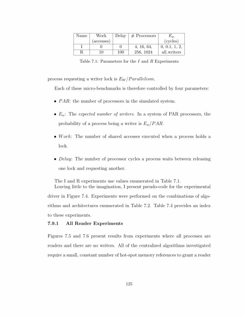
Name Work Delay # Processors Ew
(accesses) (cycles)I 0 0 4, 16, 64, 0, 0.1, 1, 2,R 10 100 256, 1024 all writers
Table 7.1: Parameters for the I and R Experiments
process requesting a writer lock is EW /Parallelism.
Each of these micro-benchmarks is therefore controlled by four parameters:
• PAR: the number of processors in the simulated system.
• Ew: The expected number of writers. In a system of PAR processors, the
probability of a process being a writer is Ew/PAR.
• Work: The number of shared accesses executed when a process holds a
lock.
• Delay: The number of processor cycles a process waits between releasing
one lock and requesting another.
The I and R experiments use values enumerated in Table 7.1.Leaving little to the imagination, I present pseudo-code for the experimental
driver in Figure 7.4. Experiments were performed on the combinations of algo-
rithms and architectures enumerated in Table 7.2. Table 7.4 provides an index
to these experiments.
7.9.1 All Reader Experiments
Figures 7.5 and 7.6 present results from experiments where all processes are
readers and there are no writers. All of the centralized algorithms investigated
require a small, constant number of hot-spot memory references to grant a reader
125
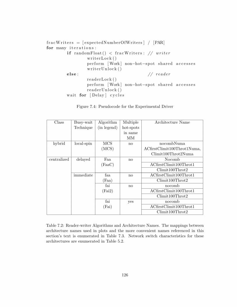
f r a cWr i t e r s = [ expectedNumberOfWriters ] / [PAR]for many i t e r a t i o n s :
i f randomFloat () < f r a cWr i t e r s : // wr i t e rwriterLock ( )perform [ Work ] non−hot−spot shared a c c e s s e swr i terUnlock ( )
else : // readerreaderLock ( )perform [ Work ] non−hot−spot shared a c c e s s e sreaderUnlock ( )
wait for [ Delay ] c y c l e s
Figure 7.4: Pseudocode for the Experimental Driver
Class Busy-wait Algorithm Multiple Architecture NameTechnique (in legend) hot-spots
in sameMM
hybrid local-spin MCS no nocombNuma(MCS) ACfirstClimit100Throt1Numa,
Climit100Throt2Numacentralized delayed Faa no Nocomb
(FaaC) ACfirstClimit100Throt1Climit100Throt2
immediate faa no ACfirstClimit100Throt1(Faa) Climit100Throt2fai no nocomb
(Fai2) ACfirstClimit100Throt1Climit100Throt2
fai yes nocomb(Fai) ACfirstClimit100Throt1
Climit100Throt2
Table 7.2: Reader-writer Algorithms and Architecture Names. The mappings betweenarchitecture names used in plots and the more convenient names referenced in thissection’s text is enumerated in Table 7.3. Network switch characteristics for thesearchitectures are enumerated in Table 5.2.
126

Architecture Name used in FiguresNon combining Nocomb
Decoupled Adaptive ACfirstClimit100Throt1Coupled Adaptive Climit100Throt2
Table 7.3: Mapping between architectures referenced in this section and the namesindicated in plots. NUMA variants, with direct PE-to-MM connections are denotedwith the suffix “nocomb”. Network switch characteristics for these architectures areenumerated in Table 5.2.
lock in the absence of contention from writers1. In contrast, the MCS algorithms
generate accesses to centralized state variables, and also construct linked lists
of requesting reader processes that are granted locks sequentially. Not surpris-
ingly, when combining is available, the centralized algorithms have dramatically
superior performance than the MCS algorithms for all-reader loads. When com-
bining is not available, serialization of accesses to the hot-spot variables con-
tributes significantly to coordination latency on systems with sixty-four or more
PEs (networks of six or more stages) for both the MCS and Faa algorithm.
In these experiments, there is no contention from writers, and centralized
algorithms issue only a small constant number of memory references each time
a reader lock is acquired or released. In the absence of contention from writers,
the “immediate” fetch-and-add algorithm requires one shared access to a hot-
spot variable, and the immediate fetch-and-increment algorithm require two.
Delayed variants generate one additional hot-spot reference and do not yield
any performance advantages since there is no contention.
The “Fai2” variant of the algorithm, which places the two hot-spot variables
1In all-reader experiments, EW = 0.
127
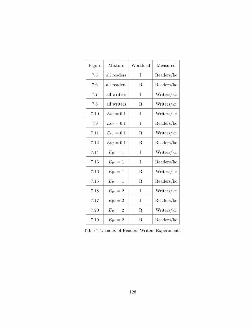
Figure Mixture Workload Measured
7.5 all readers I Readers/kc
7.6 all readers R Readers/kc
7.7 all writers I Writers/kc
7.8 all writers R Writers/kc
7.10 EW = 0.1 I Writers/kc
7.9 EW = 0.1 I Readers/kc
7.11 EW = 0.1 R Writers/kc
7.12 EW = 0.1 R Readers/kc
7.14 EW = 1 I Writers/kc
7.13 EW = 1 I Readers/kc
7.16 EW = 1 R Writers/kc
7.15 EW = 1 R Readers/kc
7.18 EW = 2 I Writers/kc
7.17 EW = 2 I Readers/kc
7.20 EW = 2 R Writers/kc
7.19 EW = 2 R Readers/kc
Table 7.4: Index of Readers-Writers Experiments
128
in distinct MMs, is slightly faster than the “Fai” algorithm where they are co-
located. As expected, the “coupled adaptive” architecture, which has lower hot-
spot latency than the “decoupled adaptive” architecture, grants reader locks at
a greater rate.
The MCS algorithm’s performance is far worse than the centralized algo-
rithms in both the I and R experiments. Differentiation among the centralized
algorithms’ performance is significant in the “intense” experiments. This differ-
entiation is masked by other costs in the more “realistic” experiment.
7.9.2 All-Writer Experiments
The MCS algorithm for reader-writer coordination has superior performance
and does not suffer from memory system bottlenecks when all requests are by
writers. In this case, the reader-writer lock simply enforces mutual exclusion,
and no speedups are possible.
When no readers are present, the rate at which writers request locks is limited
by the rate that the lock is passed from one writer to another. This is significantly
lower than the rate that a memory unit can accept memory transactions. The
MCS algorithm issues only a constant number of accesses to centralized control
variables each time the lock is requested and the subsequent passing of the
lock between processes does not generate any hot spot traffic. As a result, the
availability of combining yields no performance improvement after all writers
have issued their initial hot spot references.
The rate that writer locks are granted is higher for systems of four or more
processors than for smaller systems. This speedup is not due to parallelism
129
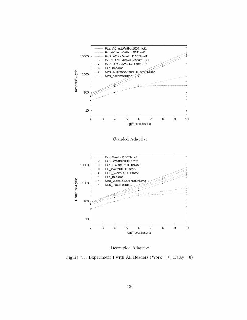
10
100
1000
10000
2 3 4 5 6 7 8 9 10
Rea
ders
/KC
ycle
log(# processors)
Faa_ACfirstWaitbuf100Throt1Fai_ACfirstWaitbuf100Throt1Fai2_ACfirstWaitbuf100Throt1FaaC_ACfirstWaitbuf100Throt1FaiC_ACfirstWaitbuf100Throt1Faa_nocombMcs_ACfirstWaitbuf100Throt1NumaMcs_nocombNuma
Coupled Adaptive
10
100
1000
10000
2 3 4 5 6 7 8 9 10
Rea
ders
/KC
ycle
log(# processors)
Faa_Waitbuf100Throt2Fai2_Waitbuf100Throt2FaaC_Waitbuf100Throt2Fai_Waitbuf100Throt2FaiC_Waitbuf100Throt2Faa_nocombMcs_Waitbuf100Throt2NumaMcs_nocombNuma
Decoupled Adaptive
Figure 7.5: Experiment I with All Readers (Work = 0, Delay =0)
130
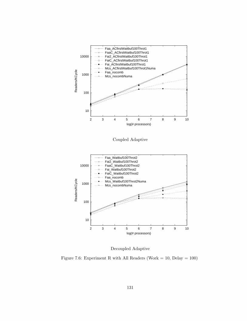
10
100
1000
10000
2 3 4 5 6 7 8 9 10
Rea
ders
/KC
ycle
log(# processors)
Faa_ACfirstWaitbuf100Throt1FaaC_ACfirstWaitbuf100Throt1Fai2_ACfirstWaitbuf100Throt1FaiC_ACfirstWaitbuf100Throt1Fai_ACfirstWaitbuf100Throt1Mcs_ACfirstWaitbuf100Throt1NumaFaa_nocombMcs_nocombNuma
Coupled Adaptive
10
100
1000
10000
2 3 4 5 6 7 8 9 10
Rea
ders
/KC
ycle
log(# processors)
Faa_Waitbuf100Throt2Fai2_Waitbuf100Throt2FaaC_Waitbuf100Throt2Fai_Waitbuf100Throt2FaiC_Waitbuf100Throt2Faa_nocombMcs_Waitbuf100Throt2NumaMcs_nocombNuma
Decoupled Adaptive
Figure 7.6: Experiment R with All Readers (Work = 10, Delay = 100)
131
of the critical section, which is impossible since the definition of reader-writer
locks requires serialization of writers. This speedup, which was also observed
by Mellor-Crummey and Scott, is due to this algorithm’s decoupling of queue
insertion and lock passing. Recall that all processes requesting entry to the
writer section must manipulate a linked-list queue. If additional writers request
the lock while it is granted to another writer, these other writer processes will
insert themselves onto the appropriate linked-list queue, readying themselves for
the passing of the writer lock, which only requires a single shared access.
In contrast, the centralized algorithms, when combining is not available, suf-
fer from hot-spot memory latency proportional to the number of processors,
leading to linear slowdown as system size increases. The latency of memory
references due to hot-spot polling, even when combining is available, is higher
than memory latency in the absence of hot-spot traffic, resulting in the greater
lock passing latency than for the MCS algorithms. As in the reader-only ex-
periments, performance of the centralized algorithms is higher for the “coupled
adaptive” combining architecture, which has significantly lower combinable hot-
spot polling latency than the “decoupled adaptive” combining architecture.
In the writer-only experiments, processes requesting the lock must serialize
and therefore will typically spend a substantial period of time busy-waiting.
After a failed initial attempt to seize a lock, a “immediate” centralized writer
executes code equivalent to the “delayed” writer. I suggest that this is why “de-
layed” and “immediate” variants of the centralized algorithms have very similar
performance in the all-writer case.
132
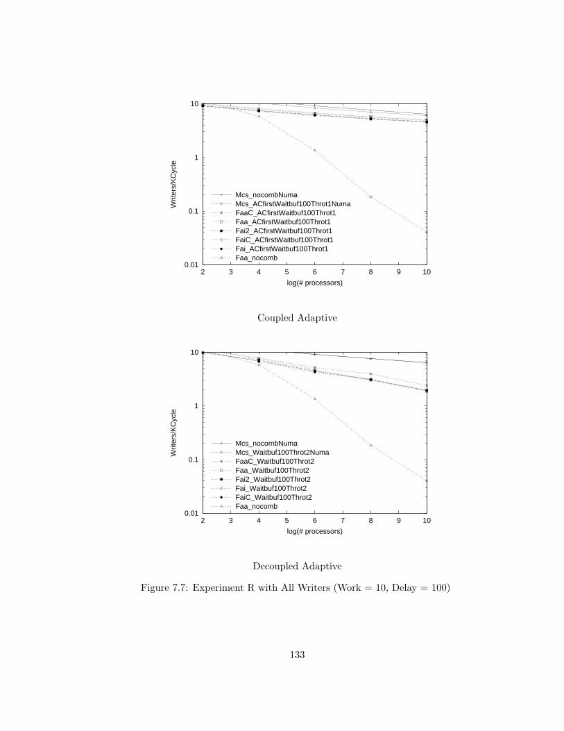
0.01
0.1
1
10
2 3 4 5 6 7 8 9 10
Writ
ers/
KC
ycle
log(# processors)
Mcs_nocombNumaMcs_ACfirstWaitbuf100Throt1NumaFaaC_ACfirstWaitbuf100Throt1Faa_ACfirstWaitbuf100Throt1Fai2_ACfirstWaitbuf100Throt1FaiC_ACfirstWaitbuf100Throt1Fai_ACfirstWaitbuf100Throt1Faa_nocomb
Coupled Adaptive
0.01
0.1
1
10
2 3 4 5 6 7 8 9 10
Writ
ers/
KC
ycle
log(# processors)
Mcs_nocombNumaMcs_Waitbuf100Throt2NumaFaaC_Waitbuf100Throt2Faa_Waitbuf100Throt2Fai2_Waitbuf100Throt2Fai_Waitbuf100Throt2FaiC_Waitbuf100Throt2Faa_nocomb
Decoupled Adaptive
Figure 7.7: Experiment R with All Writers (Work = 10, Delay = 100)
133
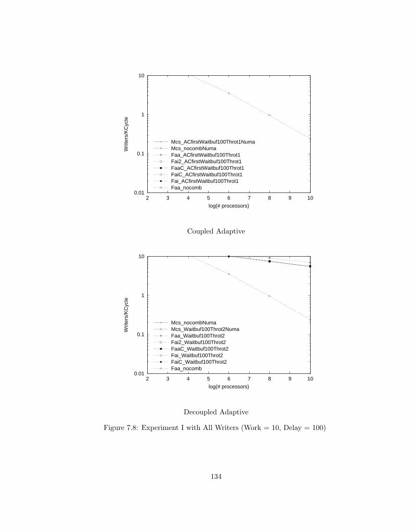
0.01
0.1
1
10
2 3 4 5 6 7 8 9 10
Writ
ers/
KC
ycle
log(# processors)
Mcs_ACfirstWaitbuf100Throt1NumaMcs_nocombNumaFaa_ACfirstWaitbuf100Throt1Fai2_ACfirstWaitbuf100Throt1FaaC_ACfirstWaitbuf100Throt1FaiC_ACfirstWaitbuf100Throt1Fai_ACfirstWaitbuf100Throt1Faa_nocomb
Coupled Adaptive
0.01
0.1
1
10
2 3 4 5 6 7 8 9 10
Writ
ers/
KC
ycle
log(# processors)
Mcs_nocombNumaMcs_Waitbuf100Throt2NumaFaa_Waitbuf100Throt2Fai2_Waitbuf100Throt2FaaC_Waitbuf100Throt2Fai_Waitbuf100Throt2FaiC_Waitbuf100Throt2Faa_nocomb
Decoupled Adaptive
Figure 7.8: Experiment I with All Writers (Work = 10, Delay = 100)
134
7.9.3 Mixed Reader-Writer Experiments
Figures 7.9 through 7.20 indicate results from experiments that investigate the
behavior of algorithms for readers and writers coordination in the presence of
both readers and writers. Four different mixtures of reader and writers are
evaluated. As described above, EW , the expected number of writers, (rather
than the probability of a process being a writer) is constant for each experiment.
When combining is available, the rate that reader locks is granted by the
centralized algorithms increases linearly with system size for all of mixed reader-
writer experiments. As with the all-reader experiments, no speedups are ob-
served for the MCS algorithm beyond sixty-four processors. For the larger
systems evaluated, performance of the centralized algorithms on combining ar-
chitectures granted both writers and readers at rates more than an order of
magnitude higher than the MCS algorithm (independent of combining) and the
fetch-and-add algorithm when combining is not available. For some experiments,
writer lock granting rates are sufficiently low that none were observed during the
duration of the experiment.
7.9.4 Stability
Unlike the centralized algorithms that continuously poll hot-spot variables until
lock acquisition, the MCS algorithm generates dramatically different memory
reference patterns when processes initially request a lock and when they are are
busy-waiting.
The processes in my micro-benchmarks commence execution simultaneously;
135
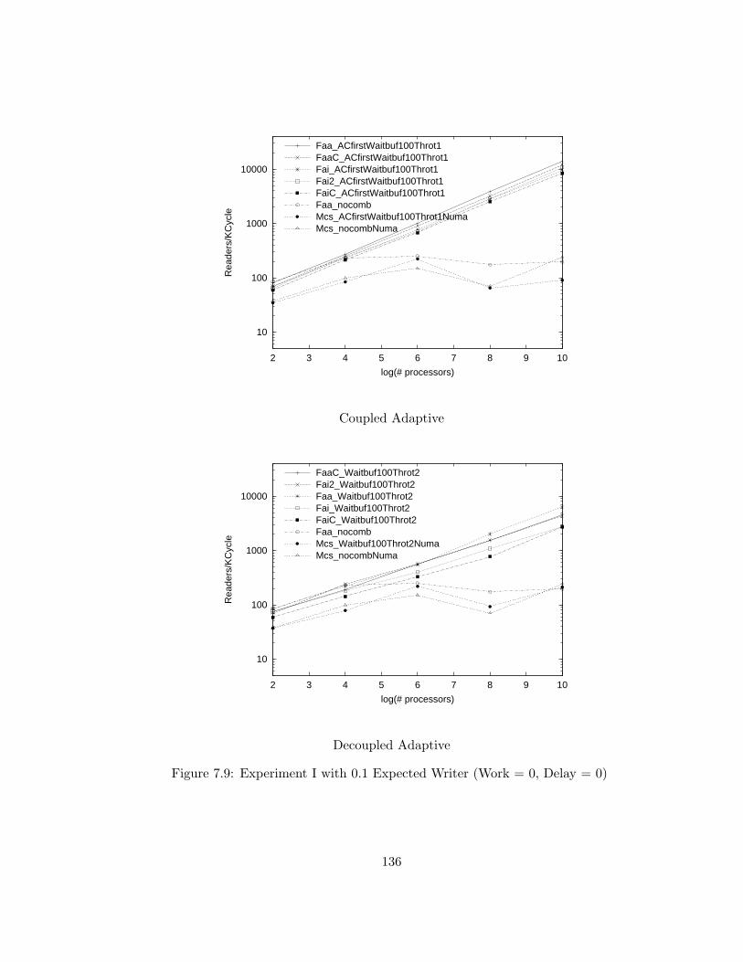
10
100
1000
10000
2 3 4 5 6 7 8 9 10
Rea
ders
/KC
ycle
log(# processors)
Faa_ACfirstWaitbuf100Throt1FaaC_ACfirstWaitbuf100Throt1Fai_ACfirstWaitbuf100Throt1Fai2_ACfirstWaitbuf100Throt1FaiC_ACfirstWaitbuf100Throt1Faa_nocombMcs_ACfirstWaitbuf100Throt1NumaMcs_nocombNuma
Coupled Adaptive
10
100
1000
10000
2 3 4 5 6 7 8 9 10
Rea
ders
/KC
ycle
log(# processors)
FaaC_Waitbuf100Throt2Fai2_Waitbuf100Throt2Faa_Waitbuf100Throt2Fai_Waitbuf100Throt2FaiC_Waitbuf100Throt2Faa_nocombMcs_Waitbuf100Throt2NumaMcs_nocombNuma
Decoupled Adaptive
Figure 7.9: Experiment I with 0.1 Expected Writer (Work = 0, Delay = 0)
136
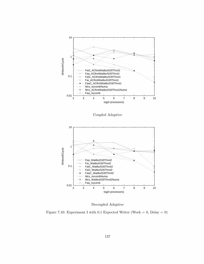
0.01
0.1
1
10
2 3 4 5 6 7 8 9 10
Writ
ers/
KC
ycle
log(# processors)
Fai2_ACfirstWaitbuf100Throt1Faa_ACfirstWaitbuf100Throt1FaiC_ACfirstWaitbuf100Throt1Fai_ACfirstWaitbuf100Throt1FaaC_ACfirstWaitbuf100Throt1Mcs_nocombNumaMcs_ACfirstWaitbuf100Throt1NumaFaa_nocomb
Coupled Adaptive
0.01
0.1
1
10
2 3 4 5 6 7 8 9 10
Writ
ers/
KC
ycle
log(# processors)
Faa_Waitbuf100Throt2Fai_Waitbuf100Throt2FaiC_Waitbuf100Throt2Fai2_Waitbuf100Throt2FaaC_Waitbuf100Throt2Mcs_nocombNumaMcs_Waitbuf100Throt2NumaFaa_nocomb
Decoupled Adaptive
Figure 7.10: Experiment I with 0.1 Expected Writer (Work = 0, Delay = 0)
137
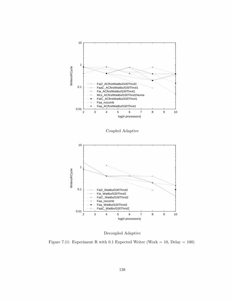
0.01
0.1
1
10
2 3 4 5 6 7 8 9 10
Writ
ers/
KC
ycle
log(# processors)
Fai2_ACfirstWaitbuf100Throt1FaaC_ACfirstWaitbuf100Throt1Fai_ACfirstWaitbuf100Throt1Mcs_ACfirstWaitbuf100Throt1NumaFaiC_ACfirstWaitbuf100Throt1Faa_nocombFaa_ACfirstWaitbuf100Throt1
Coupled Adaptive
0.01
0.1
1
10
2 3 4 5 6 7 8 9 10
Writ
ers/
KC
ycle
log(# processors)
Fai2_Waitbuf100Throt2Fai_Waitbuf100Throt2FaiC_Waitbuf100Throt2Faa_nocombFaa_Waitbuf100Throt2FaaC_Waitbuf100Throt2
Decoupled Adaptive
Figure 7.11: Experiment R with 0.1 Expected Writer (Work = 10, Delay = 100)
138
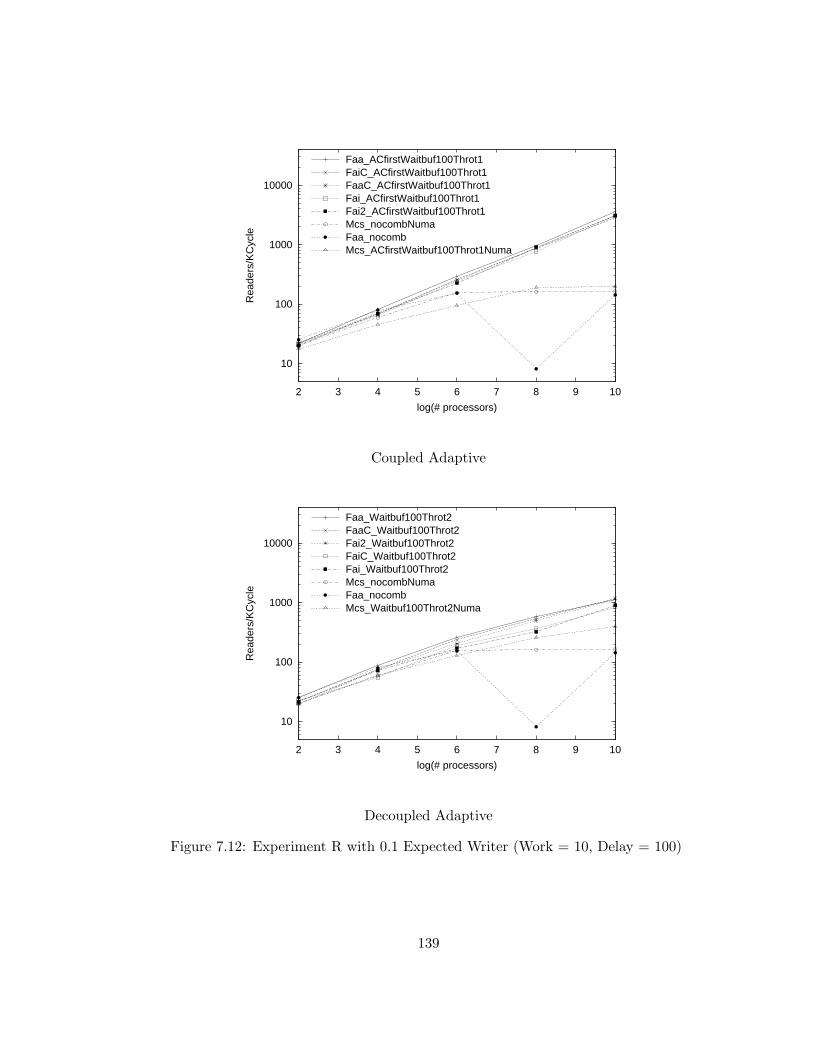
10
100
1000
10000
2 3 4 5 6 7 8 9 10
Rea
ders
/KC
ycle
log(# processors)
Faa_ACfirstWaitbuf100Throt1FaiC_ACfirstWaitbuf100Throt1FaaC_ACfirstWaitbuf100Throt1Fai_ACfirstWaitbuf100Throt1Fai2_ACfirstWaitbuf100Throt1Mcs_nocombNumaFaa_nocombMcs_ACfirstWaitbuf100Throt1Numa
Coupled Adaptive
10
100
1000
10000
2 3 4 5 6 7 8 9 10
Rea
ders
/KC
ycle
log(# processors)
Faa_Waitbuf100Throt2FaaC_Waitbuf100Throt2Fai2_Waitbuf100Throt2FaiC_Waitbuf100Throt2Fai_Waitbuf100Throt2Mcs_nocombNumaFaa_nocombMcs_Waitbuf100Throt2Numa
Decoupled Adaptive
Figure 7.12: Experiment R with 0.1 Expected Writer (Work = 10, Delay = 100)
139
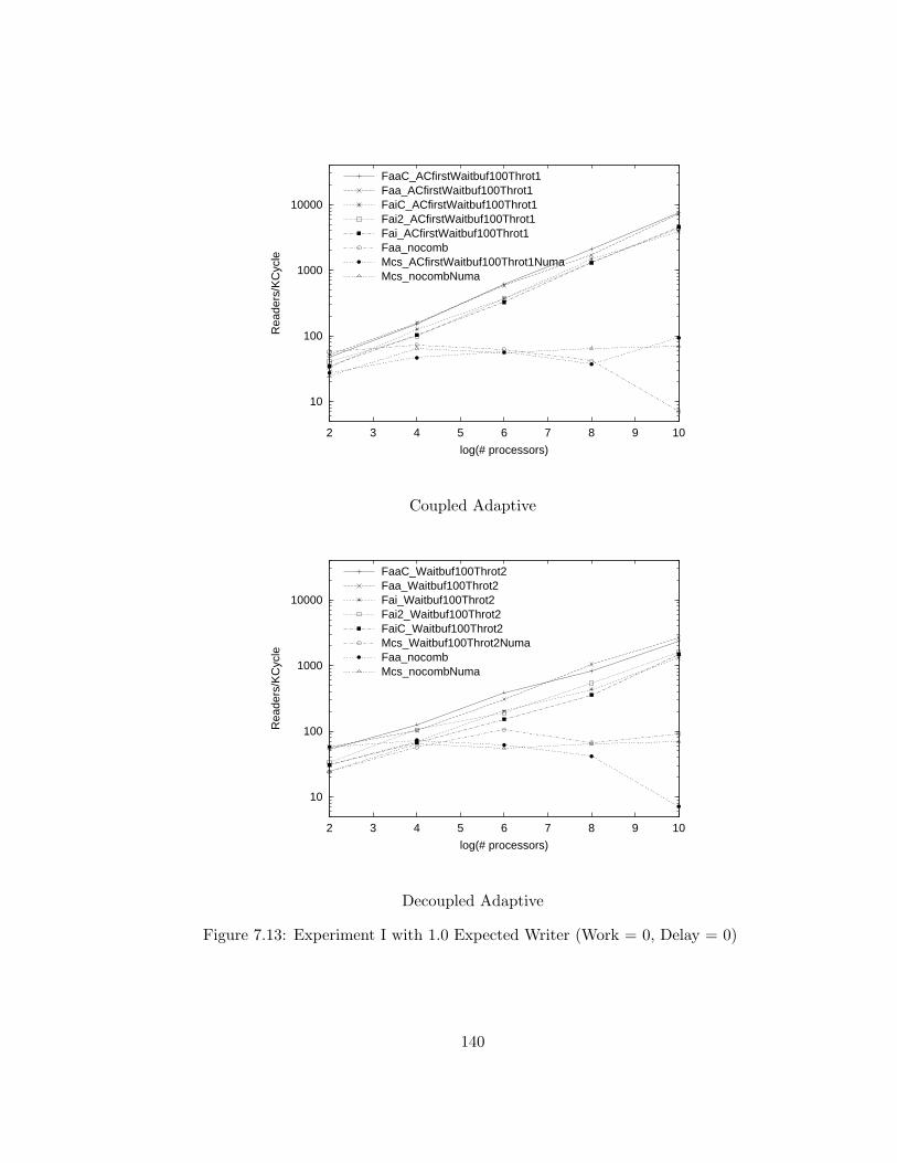
10
100
1000
10000
2 3 4 5 6 7 8 9 10
Rea
ders
/KC
ycle
log(# processors)
FaaC_ACfirstWaitbuf100Throt1Faa_ACfirstWaitbuf100Throt1FaiC_ACfirstWaitbuf100Throt1Fai2_ACfirstWaitbuf100Throt1Fai_ACfirstWaitbuf100Throt1Faa_nocombMcs_ACfirstWaitbuf100Throt1NumaMcs_nocombNuma
Coupled Adaptive
10
100
1000
10000
2 3 4 5 6 7 8 9 10
Rea
ders
/KC
ycle
log(# processors)
FaaC_Waitbuf100Throt2Faa_Waitbuf100Throt2Fai_Waitbuf100Throt2Fai2_Waitbuf100Throt2FaiC_Waitbuf100Throt2Mcs_Waitbuf100Throt2NumaFaa_nocombMcs_nocombNuma
Decoupled Adaptive
Figure 7.13: Experiment I with 1.0 Expected Writer (Work = 0, Delay = 0)
140
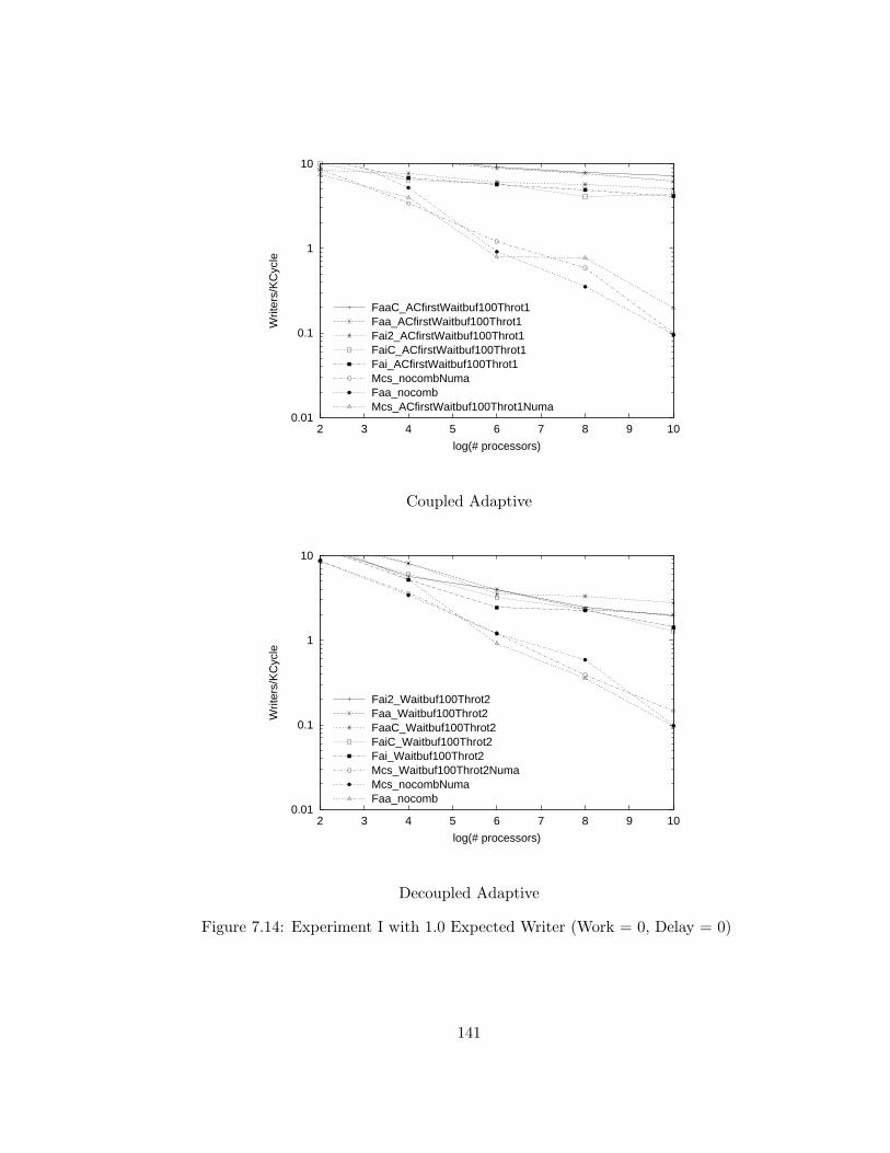
0.01
0.1
1
10
2 3 4 5 6 7 8 9 10
Writ
ers/
KC
ycle
log(# processors)
FaaC_ACfirstWaitbuf100Throt1Faa_ACfirstWaitbuf100Throt1Fai2_ACfirstWaitbuf100Throt1FaiC_ACfirstWaitbuf100Throt1Fai_ACfirstWaitbuf100Throt1Mcs_nocombNumaFaa_nocombMcs_ACfirstWaitbuf100Throt1Numa
Coupled Adaptive
0.01
0.1
1
10
2 3 4 5 6 7 8 9 10
Writ
ers/
KC
ycle
log(# processors)
Fai2_Waitbuf100Throt2Faa_Waitbuf100Throt2FaaC_Waitbuf100Throt2FaiC_Waitbuf100Throt2Fai_Waitbuf100Throt2Mcs_Waitbuf100Throt2NumaMcs_nocombNumaFaa_nocomb
Decoupled Adaptive
Figure 7.14: Experiment I with 1.0 Expected Writer (Work = 0, Delay = 0)
141
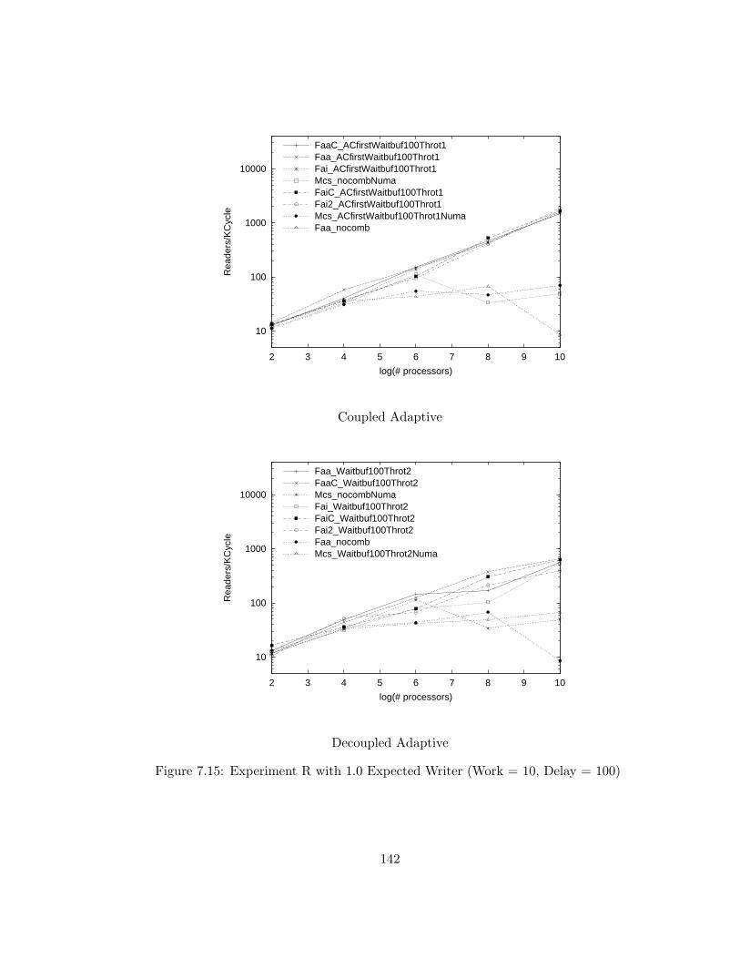
10
100
1000
10000
2 3 4 5 6 7 8 9 10
Rea
ders
/KC
ycle
log(# processors)
FaaC_ACfirstWaitbuf100Throt1Faa_ACfirstWaitbuf100Throt1Fai_ACfirstWaitbuf100Throt1Mcs_nocombNumaFaiC_ACfirstWaitbuf100Throt1Fai2_ACfirstWaitbuf100Throt1Mcs_ACfirstWaitbuf100Throt1NumaFaa_nocomb
Coupled Adaptive
10
100
1000
10000
2 3 4 5 6 7 8 9 10
Rea
ders
/KC
ycle
log(# processors)
Faa_Waitbuf100Throt2FaaC_Waitbuf100Throt2Mcs_nocombNumaFai_Waitbuf100Throt2FaiC_Waitbuf100Throt2Fai2_Waitbuf100Throt2Faa_nocombMcs_Waitbuf100Throt2Numa
Decoupled Adaptive
Figure 7.15: Experiment R with 1.0 Expected Writer (Work = 10, Delay = 100)
142
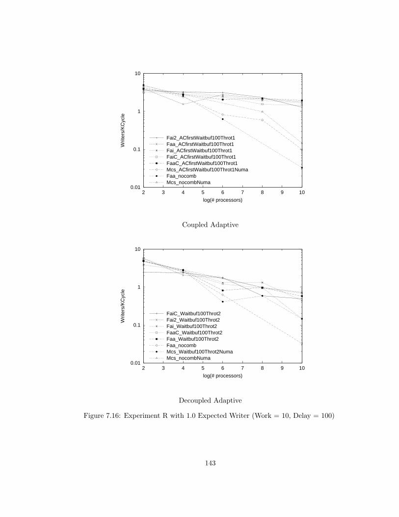
0.01
0.1
1
10
2 3 4 5 6 7 8 9 10
Writ
ers/
KC
ycle
log(# processors)
Fai2_ACfirstWaitbuf100Throt1Faa_ACfirstWaitbuf100Throt1Fai_ACfirstWaitbuf100Throt1FaiC_ACfirstWaitbuf100Throt1FaaC_ACfirstWaitbuf100Throt1Mcs_ACfirstWaitbuf100Throt1NumaFaa_nocombMcs_nocombNuma
Coupled Adaptive
0.01
0.1
1
10
2 3 4 5 6 7 8 9 10
Writ
ers/
KC
ycle
log(# processors)
FaiC_Waitbuf100Throt2Fai2_Waitbuf100Throt2Fai_Waitbuf100Throt2FaaC_Waitbuf100Throt2Faa_Waitbuf100Throt2Faa_nocombMcs_Waitbuf100Throt2NumaMcs_nocombNuma
Decoupled Adaptive
Figure 7.16: Experiment R with 1.0 Expected Writer (Work = 10, Delay = 100)
143
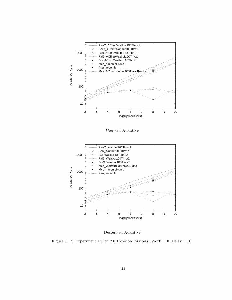
10
100
1000
10000
2 3 4 5 6 7 8 9 10
Rea
ders
/KC
ycle
log(# processors)
FaaC_ACfirstWaitbuf100Throt1FaiC_ACfirstWaitbuf100Throt1Faa_ACfirstWaitbuf100Throt1Fai2_ACfirstWaitbuf100Throt1Fai_ACfirstWaitbuf100Throt1Mcs_nocombNumaFaa_nocombMcs_ACfirstWaitbuf100Throt1Numa
Coupled Adaptive
10
100
1000
10000
2 3 4 5 6 7 8 9 10
Rea
ders
/KC
ycle
log(# processors)
FaaC_Waitbuf100Throt2Faa_Waitbuf100Throt2Fai_Waitbuf100Throt2Fai2_Waitbuf100Throt2FaiC_Waitbuf100Throt2Mcs_Waitbuf100Throt2NumaMcs_nocombNumaFaa_nocomb
Decoupled Adaptive
Figure 7.17: Experiment I with 2.0 Expected Writers (Work = 0, Delay = 0)
144
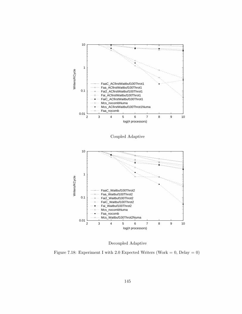
0.01
0.1
1
10
2 3 4 5 6 7 8 9 10
Writ
ers/
KC
ycle
log(# processors)
FaaC_ACfirstWaitbuf100Throt1Faa_ACfirstWaitbuf100Throt1Fai2_ACfirstWaitbuf100Throt1Fai_ACfirstWaitbuf100Throt1FaiC_ACfirstWaitbuf100Throt1Mcs_nocombNumaMcs_ACfirstWaitbuf100Throt1NumaFaa_nocomb
Coupled Adaptive
0.01
0.1
1
10
2 3 4 5 6 7 8 9 10
Writ
ers/
KC
ycle
log(# processors)
FaaC_Waitbuf100Throt2Faa_Waitbuf100Throt2Fai2_Waitbuf100Throt2FaiC_Waitbuf100Throt2Fai_Waitbuf100Throt2Mcs_nocombNumaFaa_nocombMcs_Waitbuf100Throt2Numa
Decoupled Adaptive
Figure 7.18: Experiment I with 2.0 Expected Writers (Work = 0, Delay = 0)
145
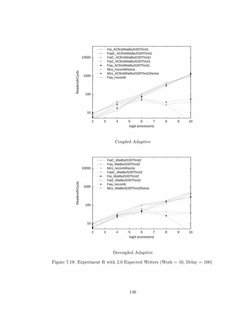
10
100
1000
10000
2 3 4 5 6 7 8 9 10
Rea
ders
/KC
ycle
log(# processors)
Fai_ACfirstWaitbuf100Throt1FaaC_ACfirstWaitbuf100Throt1FaiC_ACfirstWaitbuf100Throt1Fai2_ACfirstWaitbuf100Throt1Faa_ACfirstWaitbuf100Throt1Mcs_nocombNumaMcs_ACfirstWaitbuf100Throt1NumaFaa_nocomb
Coupled Adaptive
10
100
1000
10000
2 3 4 5 6 7 8 9 10
Rea
ders
/KC
ycle
log(# processors)
FaiC_Waitbuf100Throt2Faa_Waitbuf100Throt2Mcs_nocombNumaFaaC_Waitbuf100Throt2Fai_Waitbuf100Throt2Fai2_Waitbuf100Throt2Faa_nocombMcs_Waitbuf100Throt2Numa
Decoupled Adaptive
Figure 7.19: Experiment R with 2.0 Expected Writers (Work = 10, Delay = 100)
146

0.01
0.1
1
10
2 3 4 5 6 7 8 9 10
Writ
ers/
KC
ycle
log(# processors)
Fai2_ACfirstWaitbuf100Throt1Faa_ACfirstWaitbuf100Throt1FaaC_ACfirstWaitbuf100Throt1Fai_ACfirstWaitbuf100Throt1FaiC_ACfirstWaitbuf100Throt1Mcs_nocombNumaMcs_ACfirstWaitbuf100Throt1NumaFaa_nocomb
Coupled Adaptive
0.01
0.1
1
10
2 3 4 5 6 7 8 9 10
Writ
ers/
KC
ycle
log(# processors)
Fai2_Waitbuf100Throt2FaaC_Waitbuf100Throt2Fai_Waitbuf100Throt2Mcs_nocombNumaFaa_Waitbuf100Throt2FaiC_Waitbuf100Throt2Mcs_Waitbuf100Throt2NumaFaa_nocomb
Decoupled Adaptive
Figure 7.20: Experiment R with 2.0 Expected Writers (Work = 10, Delay = 100)
147
afterwards each process’s progress is asynchronous. To determine start-up and
steady-state effects, I sampled the lock acquisition rate at regular intervals that
I refer to as epochs.
Epoch duration was chosen to be of significant length compared to the trans-
action being performed. I chose a length of 8N cycles (where N is the number
of PEs), which approximates the time required for all participating processors
to sequentially access a single hot spot variable twice on systems that do not
implement combining. Epoch length for systems of fewer than 125 processors
are extended to 1000 cycles. The experimental results presented in this chapter
indicate the rate at which reader or writer laocks are granted during the fifth
through tenth epoch.
Measured latency during the initial epoch was often slightly worse than for
later epochs. This may be have been due to poorer initial levels of combining.
Epoch lengths are sufficiently short that, in the presence of contention, some
poorly performing algorithms will not allocate any locks during multiple epochs.
When there is substantial contention for a lock (such as for the Ew = 2
experiments in Figures 7.17 and 7.18), the immediate protocols grant locks at
a lower rate than the delayed protocols; this may be a transient live-lock effect
due to multiple requesters whose initial attempt to seize the lock both fails and
delays granting of the of the lock to other processes.
148
7.10 Chapter Conclusion
All of the algorithms for reader-writer coordination examined by my research
benefit from the availability of combining. In all cases, the centralized algo-
rithms’ performance is abysmal when combining is not available. As expected,
the MCS algorithm, which does not poll hot-spot variables, have superior per-
formance when combining is not available. When combining is available, all of
the centralized algorithms grant reader locks at a far greater rate than the MCS
algorithm.
The coupled adaptive combining architecture, has lower hot-spot polling la-
tency than the decoupled adaptive design, resulting in significantly improved
performance for the centralized algorithms.
In the all writer case where there is no contention from readers, the MCS
algorithm has superior performance to the centralized algorithms, however, the
centralized algorithms have superior performance if there is any contention from
readers.
The fetch-and-add algorithms, which generate fewer shared accesses when
granting a lock have slightly superior performance than their fetch-and-increment
counterparts.. However, this difference is dominated by other costs in the R ex-
periments that simulate a small amount of work performed between lock accesses.
These results suggest that the reader-writer problem is not very sensitive to the
availability of fetch-and-add with non-unit addends.
149
Chapter 8
Conclusions
The principal thrust of the research described in this dissertation is a comparison
of centralized coordination that exploit the availability of hardware combining
with the alternative distributed local-spin “MCS” algorithms that are commonly
used in current shared-memory systems, which do not implement combining.
Secondary contributions of this research include the detection and remediation
of problems in the previously known design for combining networks, and im-
proved algorithms and techniques for centralized coordination on systems with
combining.
8.1 Architectural Problems and their Remediation
My research indicates that the combining network incorporated in the Ultra3
prototype has high memory latency when many processors engage in hot spot
polling of a single hot-spot variable. A contribution of this dissertation is an
analysis of the causes for this high latency and techniques to substantially reduce
150
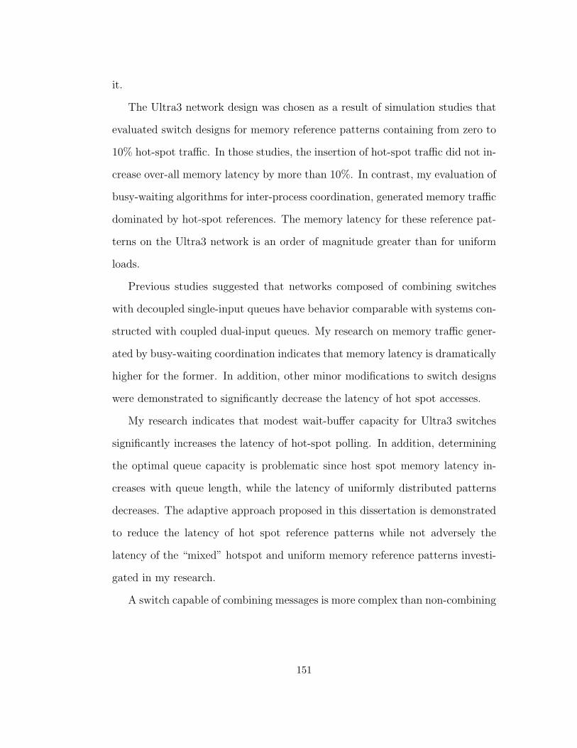
it.
The Ultra3 network design was chosen as a result of simulation studies that
evaluated switch designs for memory reference patterns containing from zero to
10% hot-spot traffic. In those studies, the insertion of hot-spot traffic did not in-
crease over-all memory latency by more than 10%. In contrast, my evaluation of
busy-waiting algorithms for inter-process coordination, generated memory traffic
dominated by hot-spot references. The memory latency for these reference pat-
terns on the Ultra3 network is an order of magnitude greater than for uniform
loads.
Previous studies suggested that networks composed of combining switches
with decoupled single-input queues have behavior comparable with systems con-
structed with coupled dual-input queues. My research on memory traffic gener-
ated by busy-waiting coordination indicates that memory latency is dramatically
higher for the former. In addition, other minor modifications to switch designs
were demonstrated to significantly decrease the latency of hot spot accesses.
My research indicates that modest wait-buffer capacity for Ultra3 switches
significantly increases the latency of hot-spot polling. In addition, determining
the optimal queue capacity is problematic since host spot memory latency in-
creases with queue length, while the latency of uniformly distributed patterns
decreases. The adaptive approach proposed in this dissertation is demonstrated
to reduce the latency of hot spot reference patterns while not adversely the
latency of the “mixed” hotspot and uniform memory reference patterns investi-
gated in my research.
A switch capable of combining messages is more complex than non-combining
151
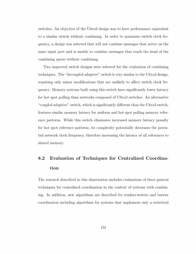
switches. An objective of the Ultra3 design was to have performance equivalent
to a similar switch without combining. In order to maximize switch clock fre-
quency, a design was selected that will not combine messages that arrive on the
same input port and is unable to combine messages that reach the head of the
combining queue without combining.
Two improved switch designs were selected for the evaluation of combining
techniques. The “decoupled adaptive” switch is very similar to the Ultra3 design,
requiring only minor modifications that are unlikely to affect switch clock fre-
quency. Memory systems built using this switch have significantly lower latency
for hot spot polling than networks composed of Ultra3 switches. An alternative
“coupled adaptive” switch, which is significantly different than the Ultra3 switch,
features similar memory latency for uniform and hot spot polling memory refer-
ence patterns. While this switch eliminates increased memory latency penalty
for hot spot reference patterns, its complexity potentially decreases the poten-
tial network clock frequency, therefore increasing the latency of all references to
shared memory.
8.2 Evaluation of Techniques for Centralized Coordina-
tion
The research described in this dissertation includes evaluations of three general
techniques for centralized coordination in the context of systems with combin-
ing. In addition, new algorithms are described for readers-writers and barrier
coordination including algorithms for systems that implement only a restricted
152
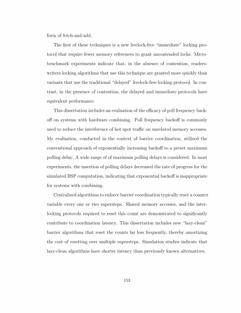
form of fetch-and-add.
The first of these techniques is a new livelock-free “immediate” locking pro-
tocol that require fewer memory references to grant uncontended locks. Micro-
benchmark experiments indicate that, in the absence of contention, readers-
writers locking algorithms that use this technique are granted more quickly than
variants that use the traditional “delayed” livelock-free locking protocol. In con-
trast, in the presence of contention, the delayed and immediate protocols have
equivalent performance.
This dissertation includes an evaluation of the efficacy of poll frequency back-
off on systems with hardware combining. Poll frequency backoff is commonly
used to reduce the interference of hot spot traffic on unrelated memory accesses.
My evaluation, conducted in the context of barrier coordination, utilized the
conventional approach of exponentially increasing backoff to a preset maximum
polling delay. A wide range of of maximum polling delays is considered. In most
experiments, the insertion of polling delays decreased the rate of progress for the
simulated BSP computation, indicating that exponential backoff is inappropriate
for systems with combining.
Centralized algorithms to enforce barrier coordination typically reset a counter
variable every one or two supersteps. Shared memory accesses, and the inter-
locking protocols required to reset this count are demonstrated to significantly
contribute to coordination latency. This dissertation includes new “lazy-clean”
barrier algorithms that reset the counts far less frequently, thereby amortizing
the cost of resetting over multiple supersteps. Simulation studies indicate that
lazy-clean algorithms have shorter latency than previously known alternatives.
153
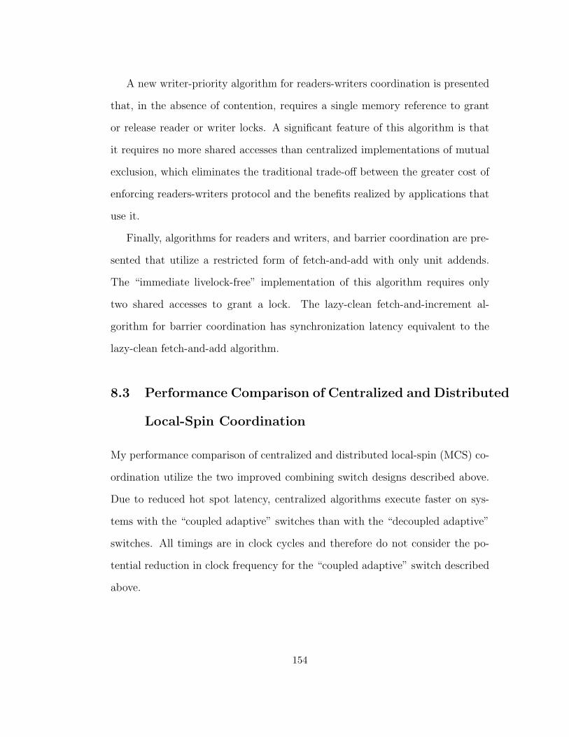
A new writer-priority algorithm for readers-writers coordination is presented
that, in the absence of contention, requires a single memory reference to grant
or release reader or writer locks. A significant feature of this algorithm is that
it requires no more shared accesses than centralized implementations of mutual
exclusion, which eliminates the traditional trade-off between the greater cost of
enforcing readers-writers protocol and the benefits realized by applications that
use it.
Finally, algorithms for readers and writers, and barrier coordination are pre-
sented that utilize a restricted form of fetch-and-add with only unit addends.
The “immediate livelock-free” implementation of this algorithm requires only
two shared accesses to grant a lock. The lazy-clean fetch-and-increment al-
gorithm for barrier coordination has synchronization latency equivalent to the
lazy-clean fetch-and-add algorithm.
8.3 Performance Comparison of Centralized and Distributed
Local-Spin Coordination
My performance comparison of centralized and distributed local-spin (MCS) co-
ordination utilize the two improved combining switch designs described above.
Due to reduced hot spot latency, centralized algorithms execute faster on sys-
tems with the “coupled adaptive” switches than with the “decoupled adaptive”
switches. All timings are in clock cycles and therefore do not consider the po-
tential reduction in clock frequency for the “coupled adaptive” switch described
above.
154
All algorithms for readers-writers coordination investigated by my research
generate hot spot reference patterns and therefore impose a serialization bot-
tleneck on readers if combining is not available. In the absence of contention,
the centralized readers and writers algorithms impose no serialization bottle-
neck when executed on a system that combines hot spot references. “Imme-
diate” variants of these algorithms generate only one shared memory reference
to grant these uncontended locks. In addition to being limited by the hot spot
performance of the underlying hardware, the MCS writer-priority reader-writer
algorithm imposes additional software bottlenecks that also limit the rate that
reader locks are granted and released. The MCS readers and writers algorithm
has inferior performance than the best centralized algorithms for all examined
workloads in which readers are present.
Overall, on large systems, the new lazy-clean barrier algorithms out-perform
the MCS dissemination algorithm by a narrow margin.
The centralized algorithms execute substantially faster with coupled adapted
switches than with decoupled adaptive switches. Dissemination does not gener-
ate hotspot accesses and therefore does not benefit from combining.
In practice, barrier synchronization is used to coordinate the progress of su-
persteps in BSP computation, and the rate of this progress (superstep latency)
is the only metric of consequence. While execution time for the short superstep
bodies utilized in my mixed and uniform workload micro-benchmark experi-
ments was significantly longer than synchronization latency, some performance
differentiation remains significant. Supersteps synchronized using the lazy-clean
(centralized) algorithms on the coupled adaptive architecture are 3-25% faster
155

than the supersteps synchronized using the dissemination algorithm. Supersteps
synchronized using the lazy-clean algorithm on the decoupled adaptive architec-
ture are not always faster, but always within 10% of the latency of supersteps
syncronized using the dissemination algorithm,
8.4 Relevance
My research indicates that the improvements to combining architectures de-
scribed in this dissertation substantially reduce the latency of hot spot accesses.
The improved centralized synchronization algorithms for high-concurrency co-
ordination are substantially superior to those previously known. The utility of
combining in potential systems depends on the benefits to applications receive
from of these improved synchronization primitives, which was not studied.
8.5 Future Work
This section enumerates several potential areas for future algorithmic and archi-
tectural research related to coordination on shared-memory systems that imple-
ment hardware combining of fetch-and-φ operations.
8.5.1 Design and Evaluation of Advanced Combining Switches
Prior work has exposed and examined a significant portion of the design space for
combining queue designs including the performance of switches with decoupled
or coupled ALUs (see Dickey[7]) and multi-input (Dickey type A) or multiplexed
single-input (Type B) combining queues.
156
The design chosen for the Ultra3 switches has multiplexed single-input com-
bining queues with decoupled ALUs. Motivations for this design include:
• The circuitry required to implement this design is simpler.
• The decoupling of ALUs from message transmission permits higher switch
clock rates.
• Prior research indicated that overall memory latency for this design was no
more than 10% greater than for the alternatives on highly loaded systems.
However, the research presented in this dissertation indicates that switches
with multi-input combining queues with coupled ALUs have significantly lower
memory latency measured in clock cycles for memory reference patterns charac-
teristic of busy-waiting. Note that a reduction of switch clock frequency that
may be required for this aggressive design increases memory latency for all mem-
ory accesses. This reduced clock frequency results in correspondingly higher
latency for all memory references, possibly dominating the advantages of the
more aggressive design. Additional research is required to determine the relative
clock-rates of switches constructed using the various potential combinations of
multiplexed-versus-multi-input and coupled-versus-decoupled combining queues.
This research will require the design, and timing evaluation of both varieties of
switches. Circuits are provided in [7] for switches implemented from multiplexed
single-input combining queues with decoupled ALUs. In [7], Dickey also presents
a dual-input combining queue design, however this circuit does not contain the
comparators necessary to combine messages that arrive simultaneously and are
transmitted in the next clock cycle.
157
8.5.2 Analysis of the Performance Benefits of Combining
More significantly, the performance advantages for application programs pro-
vided by the availability of combining networks remains unquantified. This
evaluation is made difficult by a currently pervasive bias against centralized
coordination in order to minimize hot spot congestion. It is not adequate to
model or simulate the execution of current benchmark codes for non-combining
shared-memory systems on combining systems since these codes have been op-
timized for non-combining systems. For example, while the early incarnation of
the SPLASH benchmarks [25] relied heavily upon centralized coordination, the
later incarnation [46] was substantially modified to avoid hot spot reference pat-
terns. An evaluation of these optimizations should be performed to determine
whether they result in systems with inferior performance than alternatives that
exploit the availability of combining.
Memory system design is driven by the needs of application software. These
evaluations can also yield characterizations of typical memory traffic and hot
spot reference rates for shared-memory applications that exploit centralized co-
ordination. These characterizations could motivate future evaluation and tuning
of memory system behavior.
8.5.3 Variants of the Adaptive Queue Capacity Modulation Tech-
nique
The adaptive queue length modulation technique proposed in this dissertation
sharply reduces queue capacity when the number of combined messages simul-
158
taneously enqueued exceeds a threshold. This technique is demonstrated to
reduce network latency for memory access patterns typical of hot spot polling
on systems that implement hardware combining. However, it is possible that this
technique will increase network latency for other (non hot spot-polling) memory
reference patterns.
Dickey and Liu observe that large queue capacities are required to accept
high offered loads for non-combinable traffic uniformly interleaved among MMs.
Combining is infrequent for uniformly distributed memory access patterns, and
therefore it is unlikely that they will trigger a queue length reduction. How-
ever, high offered loads dominated by random-access references with a small
background rate of combinable hot spot references may trigger the adaptive re-
duction of queue capacities and therefore reduce available bandwidth for the
uniformly distributed memory references.
The adaptive queue-capacity reduction technique is effective for reducing
latency in switches within the funnel-of-congestion caused by hot spot accesses.
Switches within this funnel are likely to combine a large fraction of the messages
they transmit. The fraction of recently transmitted messages that have combined
can easily be computed on-line; providing an alternate mechanism to trigger a
reduction of queue capacity.
Performance analysis of these variable adaptive queues should be undertaken
using memory reference patterns generated by a range of application software.
159
8.5.4 Utility of Combining Hardware for Cache Coherence Protocols
Cache coherence protocols typically manage shared (read-only) and exclusive
(read-write) copies of shared variables. Despite the obvious correspondence be-
tween cache coherence and the readers-writers coordination problem of Courtois
and Heyman [40], coherence protocols typically serialize the transmission of line
contents to individual caches. The SCI cache coherence protocol includes the
specification of a variant of combining fetch-and-store to efficiently enqueue re-
quests, however data distribution and line invalidation on network connected
systems is strictly serialized.
An extension of the general technique of combining may be able to parallelize
cache fill operations. In this case, the combining forward-path network would
collect directory information necessary to enable invalidation, and the reverse-
path network could distribute cache line data. The reverse-path decombining
network could also be utilized to broadcast both data and notification of in-
validation to multiple caches. Challenges for such schemes would include the
development of an appropriate scalable directory structure that is amenable to
(de)combinable transactions.
8.5.5 Generalization of Combining to Internet Services
The tree saturation problem due to hot spot access patterns is not unique
to shared memory systems. Congestion generated by flood attacks and flash
crowds[28] presents similar challenges for Internet network service providers. In
[36] Mahajan et al. propose a technique to limit the disruption generated by
160

hot spot congestion on network traffic with overlapping communication routes.
In their scheme, enhanced servers and routers incorporate mechanisms to char-
acterize hot spot reference patterns as aggregates. Requests to throttle the rate
at which aggregate packets are forwarded are transmitted to upstream routers.
The level of throttling is chosen to reduce or eliminate congestion in the network
core, and thereby minimize disruption for other network traffic.
Hot Spot traffic does not benefit from this scheme since the rate at which hot
spot messages are communicated to their destination does not increase. Com-
bining may provide an alternative to throttling. For example, the detection of
hot spot aggregates directed toward a web server could result in the deployment
of proxies near to network entry points, which would potentially reduce load on
the central server, thereby increasing that service’s capacity. This type of com-
bining is service-type specific and therefore service-specific strategies must be
employed. Dynamic deployment of such edge servers requires protocols for com-
municating the characteristics of hot spot aggregates to servers, and mechanisms
to dynamically install and activate upstream proxies.
Challenges related to this problem include
• The design and adoption of protocols to describe aggregates and adapta-
tions. These protocols must include representations of characteristics of
aggregates, relevant network topology, authentication, authorization, and
adaptations.
• Mutual authorization of servers and network components. This model of
combining requires that servers trust reports of hot spot aggregates from
161
network components. Similarly, adaptation requires that network compo-
nents trust messages requesting installation of proxies and special handling
of messages within an aggregate. Secure DNS [22] provides a mechanism
to map IP address spaces to entities, that can act as certificate authorities
needed to establish trust relationships.
162
Appendix A
Proof of Correctness for Polite
Fetch-and-Increment Algorithm
to Enforce Readers-Writers
Coordination
This proof is transcribed from my 1991 ASPLOS paper with Allan Gottlieb,
Process Coordination with Fetch and Increment.
The looping programs for Reader and Writer which appear in Figures A.1 and
A.2 contain the polite fetch-and-increment readers/writers algorithms of Figure
7.3. To simplify our proof, these algorithms are encoded at a lower level. The
following proof refers to this version of the algorithms.
We assume a finite set of reader processors, i.e. processors continually execut-
ing the reader program, and a finite set of writer processors. We assume further
163
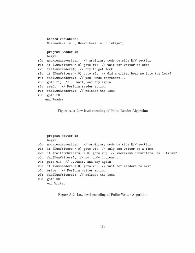
Shared variables:NumReaders := 0, NumWriters := 0: integer;
program Reader isbegin
r0: non-reader-writer; // arbitrary code outside R/W sectionr1: if (NumWriters > 0) goto r1; // wait for writer to exitr2: fai(NumReaders); // try to get lockr3: if (NumWriters = 0) goto r6; // did a writer beat me into the lock?r4: fad(NumReaders); // yes; undo increment...r5: goto r1; // ...wait, and try againr6: read; // Perform reader actionr7: fad(NumReaders); // release the lockr8: goto r0
end Reader
Figure A.1: Low level encoding of Polite Reader Algorithm
program Writer isbegin
w0: non-reader-writer; // arbitrary code outside R/W sectionw1: if (NumWriters > 0) goto w1; // only one writer at a timew2: if (fai(NumWriters) = 0) goto w5; // increment numwriters, am I first?w3: fad(NumWriters); // no, undo increment...w4: goto w1; // ...wait, and try againw5: if (NumReaders > 0) goto w5; // wait for readers to exitw6: write; // Perform writer actionw7: fad(NumWriters); // release the lockw8: goto w0
end Writer
Figure A.2: Low level encoding of Polite Writer Algorithm
164
that at time zero, the start of execution, all processors are at the first state-
ment of their respective programs and note that at this point NumReaders =
NumWriters = 0. As indicated in section 2, we use (instead of a PRAM) a
computational model in which, during each time unit, exactly one (rather than
every) processor executes one statement of its program.1 Finally, we assume that
processors are not starved, i.e. during any infinite time interval, each processor
executes infinitely often. We use the symbol⊙
to indicate the end of a proof.
To state our theorem precisely, we need the notions of state and history. The
state of an execution consists of the values of the variables and program counters.
In fact, we show below that the values of NumReaders and NumWriters, the
only variables present, are determined by the program counters and hence are
redundant. An execution history or history is a sequence of states (s0, s1, ...)
with si the state of the system at time i. That is, s0 is the initial state and si+1
results from si by having exactly one processor execute its next statement.
We use the following definitions in the proof of theorem A.
1This assumption is stronger than necessary; we make it for pedagogical reasons. For example, we
need not require that the statements read and write take only one time unit each to execute; it suffices
that each execution of read terminates in finite time. If one permits a non-terminating read, then
writers can be starved, violating part e of the theorem. The special statement non− reader−writer
represents an arbitrary code sequence modifying neither NumReaders nor NumWriters. We need
no restrictions on the time required to execute non − reader − writer; in particular, it need not
terminate. Note that the remaining statements are written at essentially the assembly language level
so it is reasonable to assume that each executes atomically. In particular, none of these statements
makes more than one reference to shared memory. We consider FAI one reference; simply place the
increment logic at the memory.
165
R is a finite set of reader processors.
W is a finite set of writer processors.
φ is the empty set.
NumWriters(t) is the value of NumWriters at time t.
NumReaders(t) is the value of NumReaders at time t.
rρ(t) is the net contribution of ρ ∈ R to NumReaders at time t, i.e. the number
of executions of fai(NumReaders) by ρ up to time t minus the number of
executions of fad(NumReaders) by ρ up to time t.
wω(t) is the analogous net contribution of ω ∈ W to NumWriters.
Stepsπ(t1, t2) is the number of statements processor π executes between times
t1 and t2.
Lπ(t) is the label of the next statement to be executed by processor π at time t.
lastπ(l, t) is the most recent time prior to t that processor π executed the state-
ment labeled l, i.e. max{i < t : Lπ(i) = l∧
Stepsπ(i, i + 1) = 1}
InRange(t, n,m) is the set of processors for which, at time t, n ≤ L(t) ≤ m,
where n and m both are statement labels in the same program and are
ordered according to their occurrence in the program.
Rreq(t) is the set of processors that are requesting to read at time t. More
precisely, Rreq(t) = InRange(t, r1, r5).
166
Rread(t) is the set of processors that are reading at time t. More precisely,
Rread(t) = InRange(t, r6, r6).
Wreq(t) is the set of processors that are requesting to write at time t. More
precisely, Wreq(t) = InRange(t, w1, w5).
Wwrite(t) is the set of processors that are writing at time t. More precisely,
Wwrite(t) = InRange(t, w6, w6).
Wactive(t) is the set of writers that are not at statement w0 at time t. More
precisely, Wactive(t) = InRange(t, w1, w8).
Requesting(t) is the set of processors that are requesting to read or requesting
to write at time t. More precisely, Requesting(t) = Rreq(t)⋃
Wreq(t).
Using the notation just introduced, we can now state and prove that the
algorithm has the characteristics described in Section 7.2, expressed formally as
Theorem A, below.
A.1 Theorem A
Any execution history of the FAI implementation of readers and writers satisfies:
a). There does not exist a time t and processors ρ ∈ R and ω ∈ W such that
Lρ(t) = r6 and Lω(t) = w6.
b). There does not exist a time t and processors ω1, ω2 ∈ W such that Lω1(t) =
Lω2(t) = w6.
167
c). For any time t, if Requesting(t) 6= φ, there exists a time t′ ≥ t such that
Rread(t′)
⋃Wwrite(t
′) 6= φ.
d). There exists a constant K (K = 5 suffices) such that for any reader ρ and
times t1 < t: If ρ ∈ Rreq(t1), Wactive(t′) = φ for all t1 ≤ t′ ≤ t2 and
Stepsρ(t1, t2) ≥ K, then ρ ∈ Rread(t) for some time t1 ≤ t ≤ t2.
e). For any time t such that Wreq(t) 6= φ, there exists t′ ≥ t such that Wwrite(t′) 6=
φ.
A.2 Proof of theorem A.
We define the label sequence of a processor π to be the sequence of labels of the
statements executed by π. A simple analysis of Reader and Writer as sequential
programs yields the following two propositions.
A.2.1 Proposition 1.
The label sequence of a single reader processor must satisfy the regular expression
(r0 r1 r1* (r2 r3 r4 r5 r1 r1*)* r2 r3 r6 r7 r8)*
Similarly, the label sequence of a single writer processor must satisfy the
regular expression
(w0 w1 w1* w2 (w3 w4 w1 w1* w2)* w5 w5* w6 w7 w8)*⊙
A.2.2 Proposition 2.
For all times t and reader processors ρ, rρ(t) is either 0 or 1, specifically, rρ(t) is
1 if and only if Li(t) ∈ {r3, r4, r6, r7}. Likewise, for all times t and writer
168
processors ω, wω(t) is either 0 or 1, specifically 1 if and only if Li(t) ∈=
{w3, w5, w6, w7}. ⊙Since clearly NumReaders(t) =
∑rρ(t) and NumWriters(t) =
∑wω(t), the
following result follows easily from Proposition 2.
A.2.3 Proposition 3.
For all times t, NumReaders(t) ≥ 0. NumReaders(t) > 0 iff there exists a
reader ρ ∈ R such that Lρ(t) ∈ {r3, r4, r6, r7}. Similarly, NumWriters(t) ≥
0. NumWriters(t) > 0 iff there exists a writer ω ∈ W such that Lω(t) ∈
{w3, w5, w6, w7}. ⊙Combining propositions 1 and 3 we obtain the following result, which asserts
that NumReaders (resp. NumWriters) is positive throughout a non-trivial
time interval preceding and containing each read (resp. write).
A.2.4 Proposition 4.
For any reader ρ, and time Tr6 such that Lρ(Tr6) = r6, we have rρ(t) = 1 for
all t satisfying lastρ(r2, Tr6) < t ≤ Tr6 and hence, for the same range of t,
NumReaders(t) > 0. For any writer ω, and time Tw7 such that Lω(Tw7) = w7,
we have rω(t) = 1 for all t satisfying lastω(w2, Tw7) < t ≤ Tw7, and hence, for
the same range of t, NumWriters(t) > 0.⊙
We now prove part a of Theorem 1, that readers and writers can not be active
simultaneously. Assume the contrary, that there exist a time T with a reader
ρ ∈ Rread(T ) and a writer ω ∈ Wwrite(T ).
Let tr2 = lastρ(r2, T ) and tr3 = lastρ(r3, T ). From proposition 1, tr2 <
169

tr3 < T . From inspection of Reader as a serial program, NumWriters(tr3) = 0.
Finally, from proposition 4, NumReaders(t) > 0 for all tr2 < t ≤ T .
Similarly, Let tw2 = lastω(w2, T ) and tw5 = lastω(w5, T ). From propo-
sition 1, tw2 < tw5 < T . From inspection of Writer as a serial program,
NumReaders(tw5) = 0. Finally, from proposition 4, NumWriters(t) > 0 for all
tw2 < t ≤ T .
But, tr3 < tw2 because NumReaders(tw5) = 0, tw5 < tr2 and, NumWriters(tr3) =
0. From this, we obtain the contradiction tr3 < tw2 < tw5 < tr2 < tr3, which
proves part a.⊙
Part b, the mutual exclusion of writers, holds because statements w5 and w6
of Writer are protected with code equivalent to the binary semaphore algorithm
proved correct in [2].⊙
We now prove part d (readers are not serialized) by showing that, in the ab-
sence of writers, any requesting reader ρ will read after executing at most 5 state-
ments. More precisely, let ρ ∈ Rreq(t1) and choose t2 such that Stepsρ(t1, t2) ≥ 5
and Wactive(t) = 0 for all t1 < t < t2. Then part d reduces to:
A.2.5 Proposition 5
There exists a t in the range t1 ≤ t ≤ t2 such that Lρ(t) = r6.
From proposition 3, NumWriters(t) = 0 for all t1 ≤ t ≤ t2. which converts
r1 to a nop and r3 to a goto. With these conversions, the label sequence of ρ,
during the time interval from t1 to t2, must be a contiguous subsequence of (a
sequence satisfying) the regular expression
r4 r5 r1 r2 r3 r6 r7 r8 (r0 r1 r2 r3 r6 r7 r8)*
170
Since Lρ(t1) ∈ {r1, r2, r3, r4, r5}, ρ will execute statement r6 (read) after no
more than five transitions, completing the proof of proposition 5 and hence the
proof of part d of Theorem A.⊙
We now prove part e: if Wreq(T ) 6= φ, there exists a time T ′ ≥ T such
that Wwrite(T′) 6= φ. The writer program is equivalent to a binary semaphore
protecting the critical section w5, w6 . The deadlock freedom of this semaphore
implies there exists a writer ω and time t ≥ T such that Lω(t) ∈ {w5, w6}. If
Lω(t) = w6, we are done. We assume instead that Lω(t′) = w5 for all t′ > t (since
the only other successor to w5 is w6). From proposition 3, NumWriters(t′) > 0
for t′ > t, which converts r3 to a nop and r1 to a nonterminating loop. Hence, the
label sequence of each reader starting at time t must be a contiguous subsequence
of ((r6r7r8r0)|(r2r3r4r5))r1∗
Since all processors make non-zero progress, there exists a time tnoR > t such
that for all t′ > tnoR and ρ ∈ R, Lρ(t′) ∈ {r0, r1}, and hence (from proposition
3), NumReaders(t′) = 0. Therefore, for all t′ > tnoR, w5 is converted to a nop
which forces ω to execute w6, completing the proof of part d.⊙
We conclude the proof of theorem A by showing that part c can be deduced
from parts d and e. Choose a time t such that Requesting(t) 6= φ. We need
to find t′ ≥ t such that Rread(t′)
⋃Wwrite(t
′) 6= φ. The idea is that a requesting
writer will write due to part e and if no writers are requesting, a requesting
reader will read due to part d.
More formally, we begin by noting that if there exists ω ∈ InRange(t, w6, w6)
the result is trivial (let t′ = t). In addition, if there exists ω ∈ InRange(t, w1, w5),
the result follows from part e. Hence we may assume that for all ω ∈ W ,
171
Lω(t) = {w0, w7, w8}.
Next observe that we may extend the last assumption to all t1 > t since if
InRange(t1, w1, w6) 6= φ, the result again follows from part e. But the only
successor to w7 is w8, the only successor to w8 is w0 and all processors make
non-zero progress. Therefore, there exists a time tnoW ≥ t such that for all
t2 > tnoW , InRange(t2, w1, w8) = φ.
We now return to time t and observe that since Wreq(t) = φ and Requesting(t) 6=
φ, we can find ρ ∈ Rreq(t). But from proposition 1, either there exists a t′ in the
range t ≤ t′ ≤ tnoW such that ρ ∈ Rread(t′) and we are done, or ρ ∈ Rreq(tnoW )
and the result follows from part d.⊙
172
Appendix B
Simulation Testbed
To support my research into the performance of busy-waiting algorithms for
inter-process coordination, I constructed USim, a scalable simulator of variants
of the NYU Ultra3 prototype. This appendix provides an overview of USim and
a description of validation experiments that compare timings collected using
USim with measurements taken using the sixteen processor Ultra3 prototype
and another simulation effort.
B.1 Overview of USim
USim provides a parameterized functional simulator of user-mode processes exe-
cuting under the Symunix operating system. Care was taken to accurately model
the timing of memory transactions generated by the micro-benchmarks executed
in my research.
The operating system run on Ultra3 is a symmetric variant of Unix Version
7 named Symunix [10]. In additional to the Version 7 API, Symunix includes
173
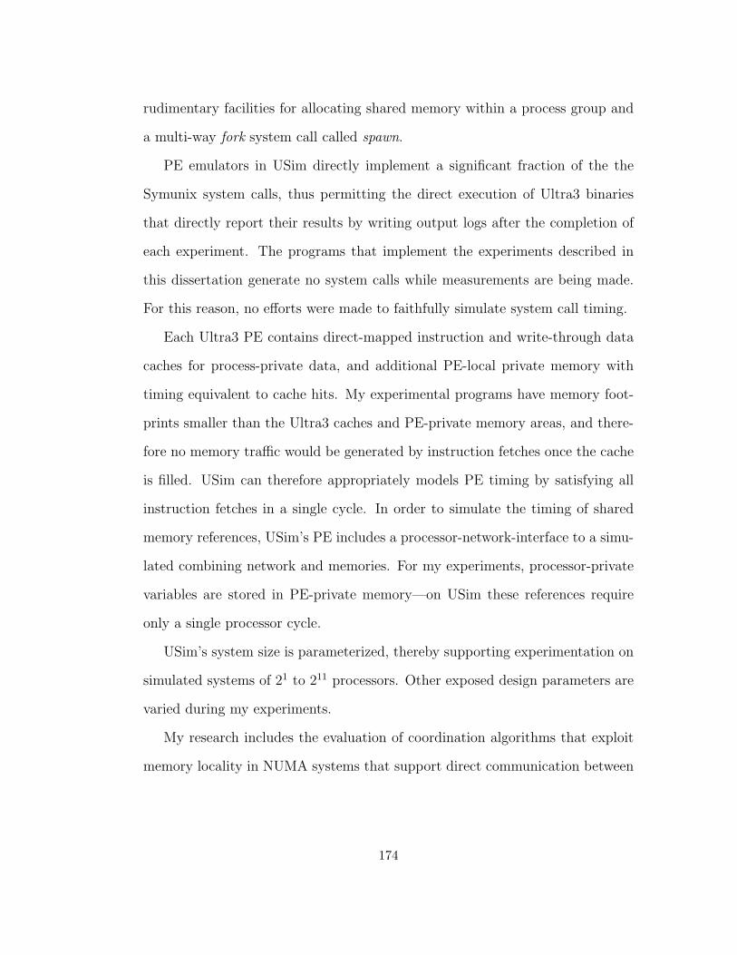
rudimentary facilities for allocating shared memory within a process group and
a multi-way fork system call called spawn.
PE emulators in USim directly implement a significant fraction of the the
Symunix system calls, thus permitting the direct execution of Ultra3 binaries
that directly report their results by writing output logs after the completion of
each experiment. The programs that implement the experiments described in
this dissertation generate no system calls while measurements are being made.
For this reason, no efforts were made to faithfully simulate system call timing.
Each Ultra3 PE contains direct-mapped instruction and write-through data
caches for process-private data, and additional PE-local private memory with
timing equivalent to cache hits. My experimental programs have memory foot-
prints smaller than the Ultra3 caches and PE-private memory areas, and there-
fore no memory traffic would be generated by instruction fetches once the cache
is filled. USim can therefore appropriately models PE timing by satisfying all
instruction fetches in a single cycle. In order to simulate the timing of shared
memory references, USim’s PE includes a processor-network-interface to a simu-
lated combining network and memories. For my experiments, processor-private
variables are stored in PE-private memory—on USim these references require
only a single processor cycle.
USim’s system size is parameterized, thereby supporting experimentation on
simulated systems of 21 to 211 processors. Other exposed design parameters are
varied during my experiments.
My research includes the evaluation of coordination algorithms that exploit
memory locality in NUMA systems that support direct communication between
174
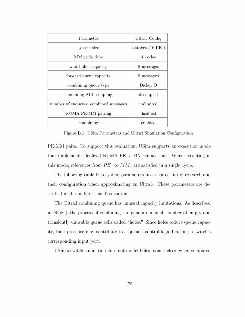
Parameter Ultra3 Config
system size 4 stages (16 PEs)
MM cycle time 4 cycles
wait buffer capacity 8 messages
forward queue capacity 8 messages
combining queue type Dickey B
combining ALU coupling decoupled
number of enqueued combined messages unlimited
NUMA PE-MM pairing disabled
combining enabled
Figure B.1: USim Parameters and Ultra3 Simulation Configuration
PE-MM pairs. To support this evaluation, USim supports an execution mode
that implements idealized NUMA PE-to-MM connections. When executing in
this mode, references from PEn to MMn are satisfied in a single cycle.
The following table lists system parameters investigated in my research and
their configuration when approximating an Ultra3. These parameters are de-
scribed in the body of this dissertation.
The Ultra3 combining queue has unusual capacity limitations. As described
in [Sni82], the process of combining can generate a small number of empty and
transiently unusable queue cells called “holes.” Since holes reduce queue capac-
ity, their presence may contribute to a queue’s control logic blocking a switch’s
corresponding input port.
USim’s switch simulation does not model holes, nonetheless, when compared
175
to timings collected using the Ultra3 prototype, observed simulation error is
always less than 25%, and generally within 5%.
B.2 Number of Concurrent Outstanding Memory Refer-
ences
An Ultra3 PE can have up to eight outstanding memory references at a time.
To support sequential consistency, the Ultra3 PE contains a fence mechanism
[PBG85] that prevents the transmission of multiple concurrent memory refer-
ences. As is typical of busy-waiting coordination algorithms, those investigated
in my research require sequential consistency, which is achieved by enabling the
fence mechanism.
USim’s simulated PEs implement the Ultra3 fence mechanism. Fencing limits
memory system load to one outstanding shared data request per processor. In
order to instrument memory system behavior under higher offered loads, some
architectural experiments were conducted with fencing disabled. In order to
accurately modulate the load generated by these experiments, USim also imple-
ments a mechanism that limits offered load to a fixed fraction of network port
bandwidth.
B.3 Validation Study for USim
I conducted Several experiments to evaluate the fidelity of measurements of
synchronization micro-benchmarks collected using USim as an emulator of the
176
Hot-spot Fraction USim Susy
10% 30 29.6
1% 24 22.8
Figure B.2: Comparison of Memory Latency Measured Using USim and Susy of 1024
PE Systems with Two Cycle MMs and 10% offered load
Ultra3 architecture.
Previous simulation studies of Ultracomputer systems were focused on mea-
surements of memory system performance in the presence of a high traffic loads.
In those experiments, the fraction of memory traffic directed towards a hot-
spot variable varied from zero to ten percent. Measurements published in Susan
Dickey’s dissertation were made using her network simulator named Susy. Few
of her experiments were appropriate for duplication using USim since they con-
sidered offered loads at higher rates than could be generated by USim’s PEs.
Figure B.2 presents round-trip memory latencies for 10% offered load on 1024
processor systems with 2-cycle MMs. These timings differ by less than 5%.
B.4 Comparison With the 16 Processor Prototype
When configured appropriately, USim has memory-system behavior that approx-
imates the as-built NYU Ultra3 system. The following experiments were timed
on both the sixteen processor Ultra3 prototype, and under simulation. For ex-
periments that require fewer than 16 PEs, PEs whose id is greater than the
required number are halted immediately. Most results are within 5%, and all
177
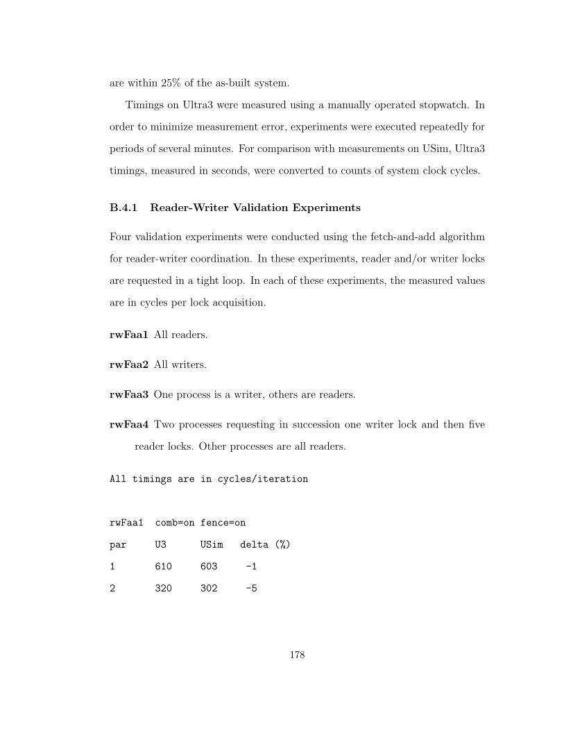
are within 25% of the as-built system.
Timings on Ultra3 were measured using a manually operated stopwatch. In
order to minimize measurement error, experiments were executed repeatedly for
periods of several minutes. For comparison with measurements on USim, Ultra3
timings, measured in seconds, were converted to counts of system clock cycles.
B.4.1 Reader-Writer Validation Experiments
Four validation experiments were conducted using the fetch-and-add algorithm
for reader-writer coordination. In these experiments, reader and/or writer locks
are requested in a tight loop. In each of these experiments, the measured values
are in cycles per lock acquisition.
rwFaa1 All readers.
rwFaa2 All writers.
rwFaa3 One process is a writer, others are readers.
rwFaa4 Two processes requesting in succession one writer lock and then five
reader locks. Other processes are all readers.
All timings are in cycles/iteration
rwFaa1 comb=on fence=on
par U3 USim delta (%)
1 610 603 -1
2 320 302 -5
178
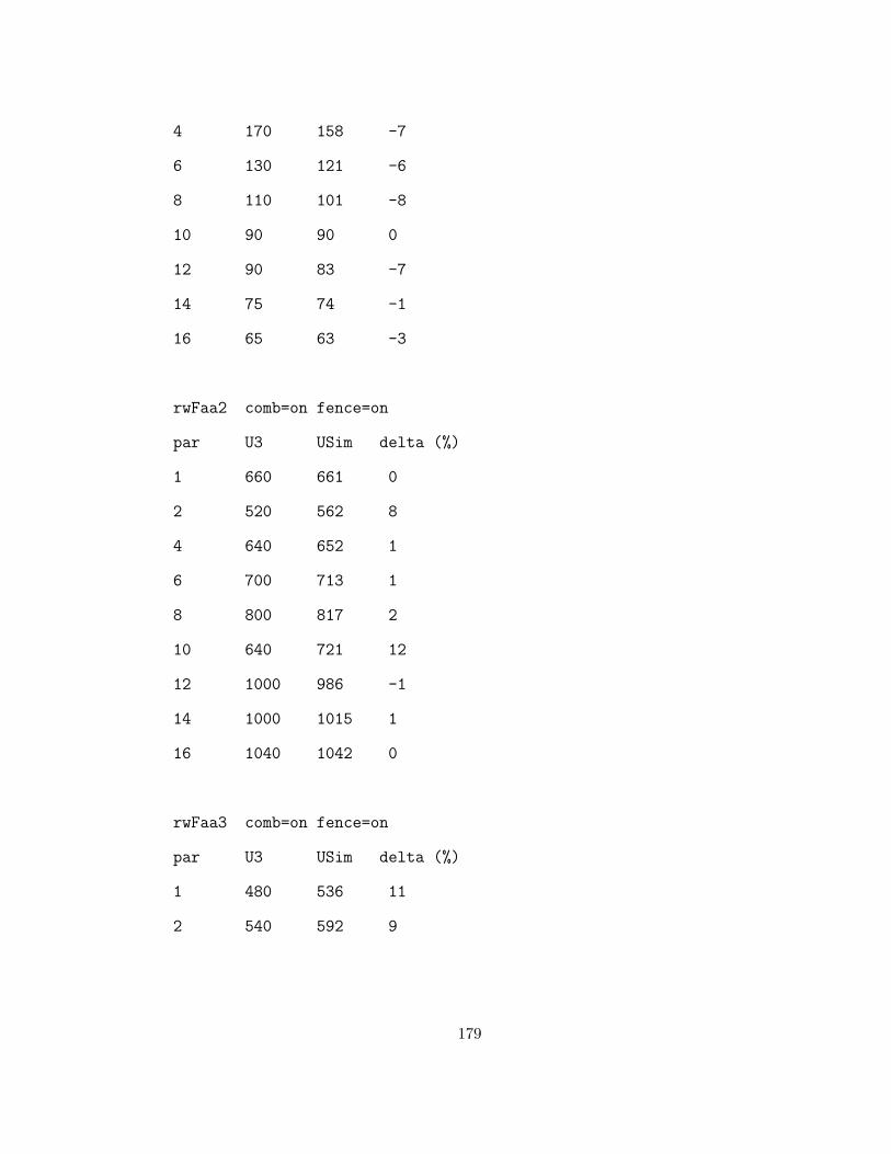
4 170 158 -7
6 130 121 -6
8 110 101 -8
10 90 90 0
12 90 83 -7
14 75 74 -1
16 65 63 -3
rwFaa2 comb=on fence=on
par U3 USim delta (%)
1 660 661 0
2 520 562 8
4 640 652 1
6 700 713 1
8 800 817 2
10 640 721 12
12 1000 986 -1
14 1000 1015 1
16 1040 1042 0
rwFaa3 comb=on fence=on
par U3 USim delta (%)
1 480 536 11
2 540 592 9
179
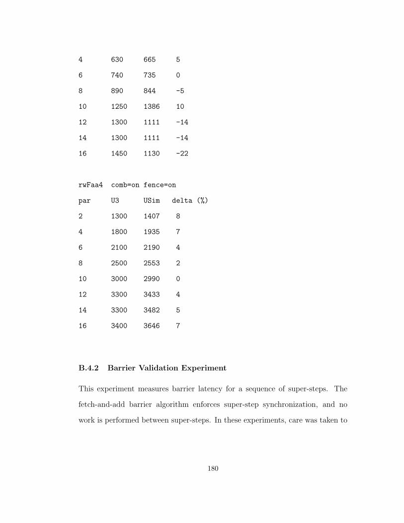
4 630 665 5
6 740 735 0
8 890 844 -5
10 1250 1386 10
12 1300 1111 -14
14 1300 1111 -14
16 1450 1130 -22
rwFaa4 comb=on fence=on
par U3 USim delta (%)
2 1300 1407 8
4 1800 1935 7
6 2100 2190 4
8 2500 2553 2
10 3000 2990 0
12 3300 3433 4
14 3300 3482 5
16 3400 3646 7
B.4.2 Barrier Validation Experiment
This experiment measures barrier latency for a sequence of super-steps. The
fetch-and-add barrier algorithm enforces super-step synchronization, and no
work is performed between super-steps. In these experiments, care was taken to
180
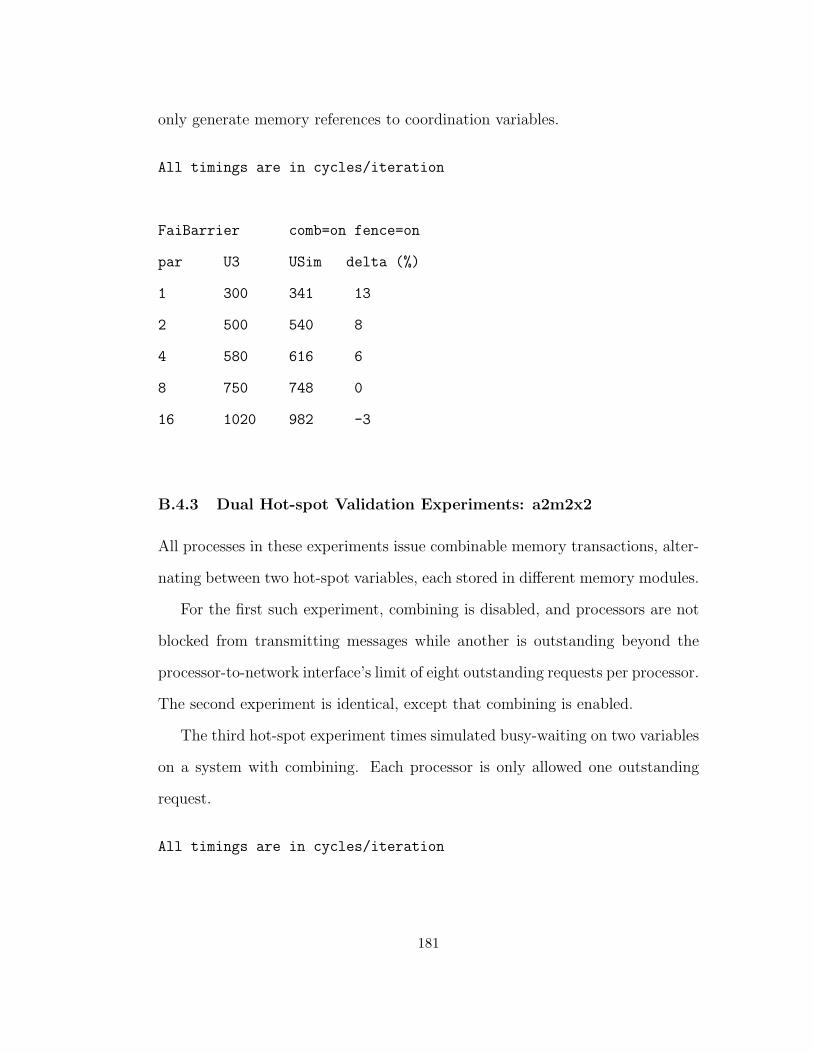
only generate memory references to coordination variables.
All timings are in cycles/iteration
FaiBarrier comb=on fence=on
par U3 USim delta (%)
1 300 341 13
2 500 540 8
4 580 616 6
8 750 748 0
16 1020 982 -3
B.4.3 Dual Hot-spot Validation Experiments: a2m2x2
All processes in these experiments issue combinable memory transactions, alter-
nating between two hot-spot variables, each stored in different memory modules.
For the first such experiment, combining is disabled, and processors are not
blocked from transmitting messages while another is outstanding beyond the
processor-to-network interface’s limit of eight outstanding requests per processor.
The second experiment is identical, except that combining is enabled.
The third hot-spot experiment times simulated busy-waiting on two variables
on a system with combining. Each processor is only allowed one outstanding
request.
All timings are in cycles/iteration
181
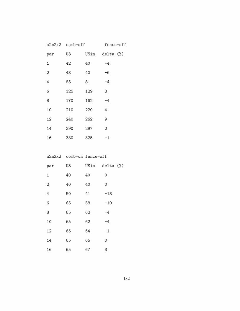
a2m2x2 comb=off fence=off
par U3 USim delta (%)
1 42 40 -4
2 43 40 -6
4 85 81 -4
6 125 129 3
8 170 162 -4
10 210 220 4
12 240 262 9
14 290 297 2
16 330 325 -1
a2m2x2 comb=on fence=off
par U3 USim delta (%)
1 40 40 0
2 40 40 0
4 50 41 -18
6 65 58 -10
8 65 62 -4
10 65 62 -4
12 65 64 -1
14 65 65 0
16 65 67 3
182
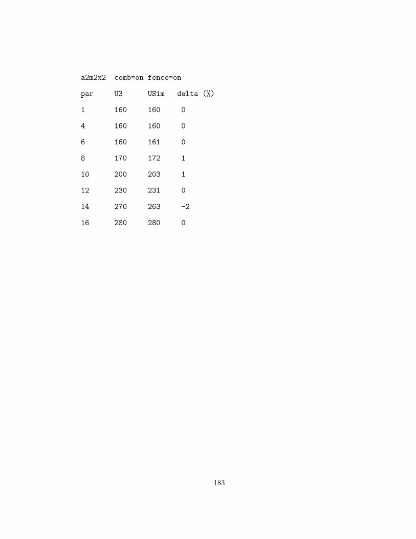
a2m2x2 comb=on fence=on
par U3 USim delta (%)
1 160 160 0
4 160 160 0
6 160 161 0
8 170 172 1
10 200 203 1
12 230 231 0
14 270 263 -2
16 280 280 0
183
Appendix C
Centralized Fuzzy Barriers
The algorithms for barriers that appear below contain a call to fuzzyWork()
which represents execution that is permitted while other processes are between
barrier calls. FuzzyWork is always called in a manner that does not delay other
processes from proceeding with barrier execution, and minimizes the time spent
busy-waiting.
184
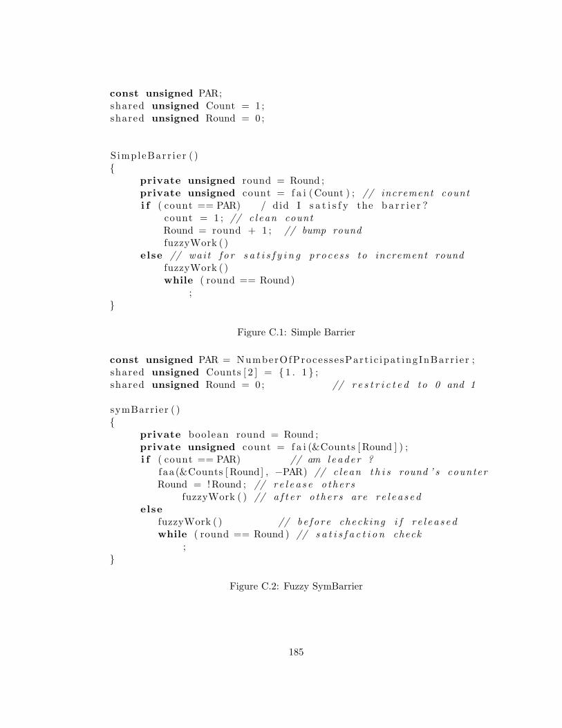
const unsigned PAR;shared unsigned Count = 1 ;shared unsigned Round = 0;
S impleBarr i e r ( ){
private unsigned round = Round ;private unsigned count = f a i (Count ) ; // increment counti f ( count == PAR) / did I s a t i s f y the b a r r i e r ?
count = 1 ; // c l ean countRound = round + 1 ; // bump roundfuzzyWork ( )
else // wai t f o r s a t i s f y i n g proces s to increment roundfuzzyWork ( )while ( round == Round)
;}
Figure C.1: Simple Barrier
const unsigned PAR = NumberOfProces se sPart i c ipat ingInBarr i e r ;shared unsigned Counts [ 2 ] = { 1 . 1 } ;shared unsigned Round = 0; // r e s t r i c t e d to 0 and 1
symBarrier ( ){
private boolean round = Round ;private unsigned count = f a i (&Counts [ Round ] ) ;i f ( count == PAR) // am l eade r ?
f aa (&Counts [ Round] , −PAR) // c l ean t h i s round ’ s counterRound = !Round ; // r e l e a s e o the r s
fuzzyWork ( ) // a f t e r o the r s are r e l e a s e delse
fuzzyWork ( ) // be f o r e check ing i f r e l e a s e dwhile ( round == Round ) // s a t i s f a c t i o n check
;}
Figure C.2: Fuzzy SymBarrier
185

shared unsigned Count = 1 ;f a aBa r r i e r ( ){
unsigned count = faa (Count , 1 ) ;i f ( count == (2 ∗ PAR) ) // r e s e t count & r e l e a s e i f even
f aa (Count , − ( 2 ∗ PAR))fuzzyWork ( ) // a f t e r o the r s are r e l e a s e d
else i f ( count != PAR) { // wai t f o r phase sw i t chbool oddPhase = count <= PAR;fuzzyWork ( ) // be f o r e wa i t ing f o r o t he r s . . . .while ( oddPhase == (Count <= PAR))
sk ip ;}
}
Figure C.3: Fuzzy FaaBarrier
shared unsigned Count = 1 ;f a i B a r r i e r ( ){
unsigned count = faa (Count , 1 ) ;i f ( count == (2 ∗ PAR) ) // r e s e t count on even phases
f aa (Count , − ( 2 ∗ PAR))fuzzyWork ( ) // a f t e r o the r s are r e l e a s e d
else i f ( count != PAR) { // wai t f o r phase sw i t chbool oddPhase = count <= PAR;fuzzyWork ( ) // be f o r e busy−wai t ingwhile ( oddPhase == (Count <= PAR))
sk ip ;}
}
Figure C.4: Fuzzy FaiBarrier
186

l a zyCleanFa iBar r i e r ( ){
int count = f a i (&Count ) ;i f ( ( ( count % par ) == 0) // I s a t i s f i e d b a r r i e r
&& count >= BIG) // && clean needed?Count = 1 // r e s e t count (& round )fuzzyWork ( )
} else {int remainder = par − count % par ; // # s lowpokesi f ( count + remainder >= BIG) // wai t f o r c l ean ?
fuzzyWork ( )while ( Count >= par ) ;
else { // normal ( no−c l ean ) caseint round = count / PAR; // wai t f o r round to changefuzzyWork ( )while ( Count / PAR != round )
sk ip ;}
}}
Figure C.5: Fuzzy Lazy-Clean Fai BarrierLazyCleanFaaBarrier ( ){
int count = f a i (&Count ) ;i f ( ( ( count % par ) == 0) // I s a t i s f i e d b a r r i e r .
&& (count >= BIG ) ) { // && time to c l ean ?int addend = count ; // compute c l ean amount .i f ( addend mod ( 2 ∗ par ) ) // ad ju s t to mu l t i p l e o f 2∗ par
addend −= par ;faa (&Count , −addend ) ; // c l ean CountfuzzyWork ( )
} else {fuzzyWork ( )bool round = oddRound( count , par ) ;while ( oddRound(Count , par ) == round )
sk ip ;}
}
Figure C.6: Fuzzy Lazy-Clean Faa Barrier
187
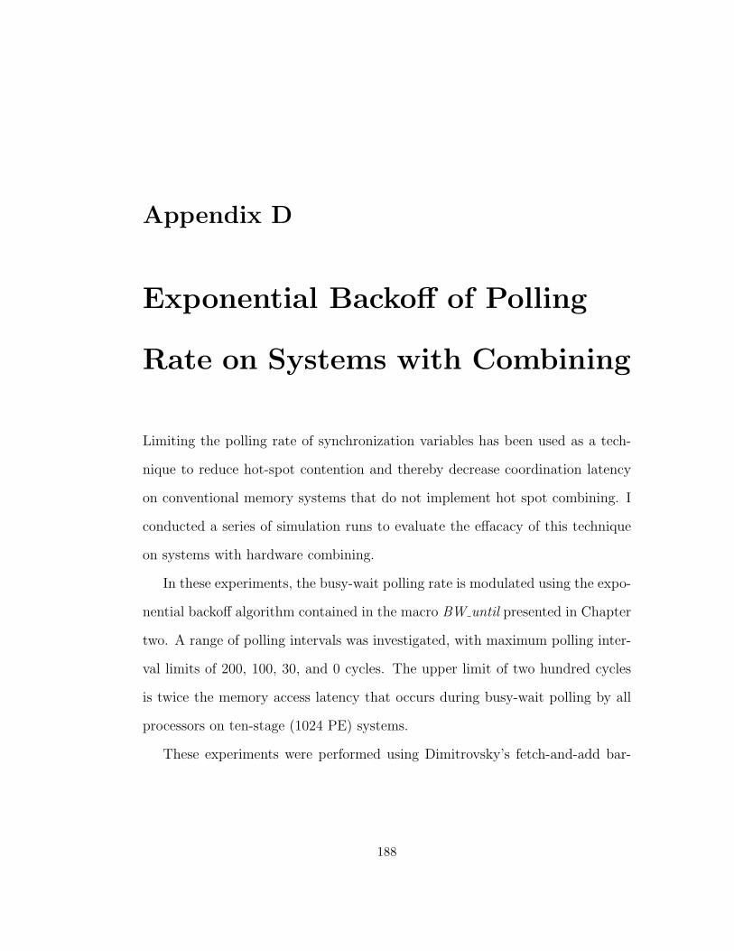
Appendix D
Exponential Backoff of Polling
Rate on Systems with Combining
Limiting the polling rate of synchronization variables has been used as a tech-
nique to reduce hot-spot contention and thereby decrease coordination latency
on conventional memory systems that do not implement hot spot combining. I
conducted a series of simulation runs to evaluate the effacacy of this technique
on systems with hardware combining.
In these experiments, the busy-wait polling rate is modulated using the expo-
nential backoff algorithm contained in the macro BW until presented in Chapter
two. A range of polling intervals was investigated, with maximum polling inter-
val limits of 200, 100, 30, and 0 cycles. The upper limit of two hundred cycles
is twice the memory access latency that occurs during busy-wait polling by all
processors on ten-stage (1024 PE) systems.
These experiments were performed using Dimitrovsky’s fetch-and-add bar-
188

50
100
150
200
250
300
350
2 3 4 5 6 7 8 9 10
Sup
erst
ep L
aten
cy (
cycl
es)
log(# processors)
FaaSpin30FaaSpin200FaaSpin100Faa
Figure D.1: Superstep latency, in cycles, Workload Wi, over a range of polling intervals.
rier algorithm (FAA) on the decoupled architecture (CombThrot2Waitbuf100)
for workloads Wi, Wu, and Wm as described in Chapter four. These results,
illustrated in Figures D.1, D.2, and D.3, indicates that reducing the polling rate
through exponential backoff is unsuccessful at reducing superstep latency.
189
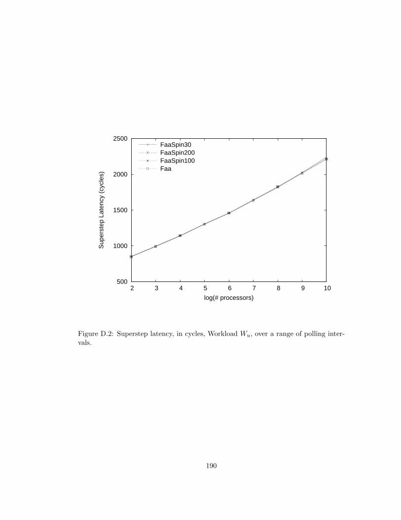
500
1000
1500
2000
2500
2 3 4 5 6 7 8 9 10
Sup
erst
ep L
aten
cy (
cycl
es)
log(# processors)
FaaSpin30FaaSpin200FaaSpin100Faa
Figure D.2: Superstep latency, in cycles, Workload Wu, over a range of polling inter-vals.
190
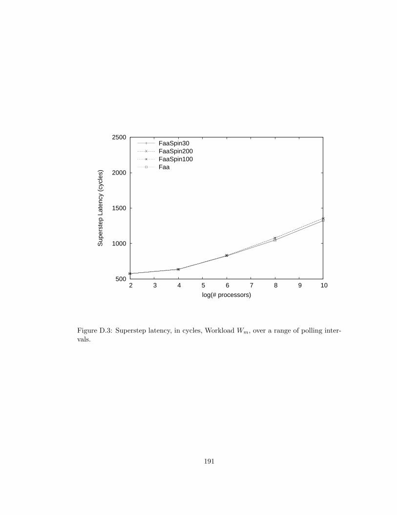
500
1000
1500
2000
2500
2 3 4 5 6 7 8 9 10
Sup
erst
ep L
aten
cy (
cycl
es)
log(# processors)
FaaSpin30FaaSpin200FaaSpin100Faa
Figure D.3: Superstep latency, in cycles, Workload Wm, over a range of polling inter-vals.
191
Bibliography
[1] Larry Rudolph ad Zary Segall. Dynamic decentralized cache schemes for
mimd parallel processors. In Proc. ISCA 11, pages 340–347, June 1984.
[2] Allan Gottlieb, Boris Lubachevsky, and Larry Rudolph. Basic Techniques
for the Efficient Coordination of Very Large Numbers of Cooperating Se-
quential Processors . ACM TOPLAS, pages 164–189, April 1983.
[3] Constantine D. Polychronopoulos Carl J. Beckmann. Fast barrier synchro-
nization hardware. In Proc. 1990 Conference on Supercomputing, pages
180–189. IEEE Computer Society Press, 1990.
[4] Burroughs Corp. Numerican aerodynamic simulation facility feasibility
study. Technical report, NASA, March 1979.
[5] IBM Corporation. IBM System 370 Principles of Operation. IBM Corpo-
rationm Poughkeepsie, NY, 7 edition, 1980.
[6] Advanced Micro Devices. AM29050 Microprocessor Users Manual. Ad-
vanced Micro Devices, 1991.
192
[7] Susan R. Dickey. Systolic Combining Switch Designs. PhD thesis, Courant
Institute, New York Univeristy, New York, 1994.
[8] E.W. Dijkstra. Hierarchical orderings of sequential processes. In C. A. R.
Hoare and R. H. Perrot, editor, Operating Systems Techniques. Academic
Press, 1972.
[9] Isaac Dimitrovsky. ZLISP-A Portable Parallel LISP Environment. PhD
thesis, Courant Institute, New York University, New York, 1988.
[10] Jan Edler. Practical Structures for Parallel Operating Systems. PhD thesis,
New York University, 1995.
[11] Steven Fortune and James Wylie. Parallelism in random access machines.
In Proc. 10th ACM Symp. on Theory of Computation, pages 114–118, 1978.
[12] Eric Freudenthal and Allan Gottlieb. Process coordination with fetch-and-
increment. In Proc. ASPLOS IV, pages 260–268, 1991.
[13] Gary Graunke and Shreekant Thakkar. Synchronization Algorithms for
Shared-Memory Multiprocessors. IEEE Computer, 1990.
[14] Gjyngho Lee, C. P. Kruskal, and D. J. Kuck. On the Effectiveness of Com-
bining in Resolving ‘Hot Spot’ Contention. Journal of Parallel and Dis-
tributed Computing, 20(2), February 1985.
[15] Allan Gottlieb. An overview of the nyu ultracomputer project. Technical
Report UCN-100, Courant Institute, New York University, 1986.
193
[16] Gregory F. Pfister, V. Alan Norton. “1Hot Spot” Contention and Combining
in Multistage Interconnection Networks. IEEE Transactions on Computers,
c-34(10), October 1985.
[17] Gregory F. Pfister, William C. Brantley, David A. George, Steve L. Harvey,
Wally J. Kleinfielder, Kevin P. McAuliffe, Evelin S. Melton, V. Alan Norton,
and Jodi Weiss. The ibm research parallel processor prototype (rp3). In
Proc. ICPP, pages 764–771, 1985.
[18] Ultracomputer Research Group. How to Write Parallel Programs for the
NYU Ultracomputer Prototype. New York University, New York, 1987.
[19] Ultracomputer Research Group. NYU Ultracomputer Unix Programmer’s
Manual. New York University, New York, 1987.
[20] Hensgen, Finkel, and Manber. Two algorithms for barrier synchronization.
International Journal of Parallel Programming, 17(1):1–17, 1988.
[21] Maurice Herlihy. A methodology for implementing highly concurrent data
objects. ACM Transactions on Programming Languages and Systems,
15(5):745–770, November 1993.
[22] IETF. Rfc 2931: Dns request and transaction signatures.
http://www.ietf.org/rfc/rfc2931.txt, Sept 2000.
[23] James Laudon , Daniel Lenoski. The SGI Origin: a ccNUMA highly scalable
server. ACM SIGARCH Computer Architecture News, 1997.
194
[24] James R. Goodman, Mary K. Vernon, and Phillip J. Woest. Efficient syn-
chronization primitives for large-scale cache-coherent multiprocessors. In
Proc. ASPLOS III, pages 64–65, April 1989.
[25] Jaswinder Pal Singh, Wolf-Dietrich Weber, and Anoop Gupta. Splash: Stan-
ford parallel applicatins for shared-memory. Computer Architecture News,
20(1):5–44, 1992.
[26] John M. Mellor-Crummey and Michael L. Scott. Scalable Reader-Writer
Synchronization for Shared Memory Multiprocessors. ACM Trans. Comput.
Systems, 9(1):21–65, 1991.
[27] John M. Mellor-Crummey and Michael L. Scott. Synchronization without
contention. In Proc. ISCA IV, pages 269–278, 1991.
[28] ”J. Jung, B. Krishnamurthy, and M. Rabinovich”. ”flash crowds and de-
nial of service attacks: Characterization and implications for cdns and web
sites”. In Proc. International World Wide Web Conference, pages 252–262.
”IEEE”, May ”2002”.
[29] P. Kermani and Leonard Kleinrock. Virtual Cut-through: A new computer
communication switching technique. Computer Networks, 3:267–286, 1979.
[30] Clyde Kruskal. Some results on multistage interconnection networks for
multiprocessors. Technical report, Courant Institute, New York University,
1982.
[31] Clyde P. Kruskal. Upper and Lower Bounds on the Performance of Parallel
Algortithms. PhD thesis, Courant Institute, NYU, 1981.
195

[32] Clyde P. Kruskal and Marc Snir. The preformance of multisatge inter-
connection networks for ultiprocessors. IEEE Transactions on Computers,
32(12):1091–1098, December 1983.
[33] Duncan H. Laurie. Access and alignment of data in an array processor.
IEEE Transactions on Computers, December 1975.
[34] Leo J. Guibas and Frank Liang. Systolic Stacks, Queues, and Counters. In
MIT Conference on Research in VLSI, pages 155–162, 1982.
[35] Yue-Sheng Liu. Architecture and Performance of Processor-Memory Inter-
connection Networks for MIMD Shared Memory Parallel Processing Sys-
tems. PhD thesis, New York University, 1990.
[36] R. Mahajan, S. Bellovin, S. Floyd, J. Vern, and P. Scott. Controlling high
bandwidth aggregates in the network, 2001.
[37] Jon A. Solworth Marc Snir. Ultracomputer Note 39, The Ultraswitch -
A VLSI Network Node for Parallel Processing. Technical report, Courant
Institute, New York University, 1984.
[38] John M. Mellor-Crummey and Michael L. Scott. Algorithms for scalable
synchronization on shared-memory multiprocessors. ACM Transactions on
Computer Systems, 9(1):21–65, 1991.
[39] Michael Scott, John Mellor-Crummey. Fast, contention-free combining tree
barriers. International Journal of Parallel Programming, August 1994.
196

[40] P. Courtois, F. Heymans, and D. Parnas. Concurrent control with readers
and writers. Comm. ACM, 14(10):667–668, October 1971.
[41] Janak H. Patel. Processor-memory interconnections for multiprocessors. In
Proc. Sixth Annual Symposium on Computer Architecture, ACM SIGARCH,
pages 168–177. ACM SIGARCH, April 1979.
[42] Gary L. Peterson. Myths about the mutual exclusion problem. Information
Processing Letters, 12(3):115–116, 1981.
[43] Rajiv Gupta. The Fuzzy Barrier: A Mechanism for High Speed Synchro-
nization of Processors. In Proc. ASPLOS III, pages 54–74, 1989.
[44] Randall D. Rettberg, William R. Crowther, Phillip P. Carvey. The Monarch
Parallel Processor Hardware Design. IEEE Computer, pages 18–30, April
1990.
[45] Larry Rudolph. Software Structures for Ultaparallel Computing. PhD thesis,
New York University, December 1981.
[46] Steven Cameron Woo, Mariyoshi Ohara, Evan Torrie, Jaswinder Pal Singh,
and Anoop Gupta. The splash-2 programss: Characterization and method-
ological considerations. In Proc. ISCA 22, pages 24–36, 1995.
[47] Harold Stone. Parallel processing with the perfect shuffle. IEEE Trans.
Computing, C-25(20):55–65, 1971.
[48] T.E. Anderson, E.D. Lazowska, and H.M. Levy. The Performance Implica-
197
tions of Thread Management Alternatives for Shared-Memory Multiproces-
sors. Performance Evaluation Review, 38(12):1631–1644, December 1989.
[49] Leslie G. Valiant. A bridging model for parallel computation. CACM,
33(8):103–111, 1990.
[50] James Wilson. Operating System Data Structures for Shared-Memory
MIMD Machines with Fetch-and-Add. PhD thesis, New York University,
1988.
198