Comparator Selection Guide 2007 - Analog Devices · Screen shot of interactive selection table....
4
Comparator Selection Guide 2007 www.analog.com/everywhere
Transcript of Comparator Selection Guide 2007 - Analog Devices · Screen shot of interactive selection table....
Comparator Selection Guide 2007
www.analog.com/everywhere
ADCMP341
INA_U
VINA
INA_L
OUTB
OUTA
VCC
GND
MU
X
INB_U
VINB
INB_L MU
X
400mV
ADCMP343
INA_U
VINA
INA_L
OUTB
OUTA
VCC
GND
MU
X
INB_U
VINB
INB_L MU
X
400mV
ADCMP341ADCMP343
$0.90$0.90
APPLICATIONS
Portable applications
Li-Ion monitoring
Handheld instruments
LED/relay driving
Opto-isolator driving
Control systems
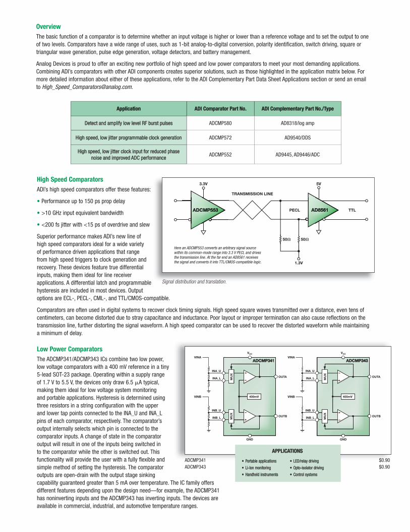
Overview
The basic function of a comparator is to determine whether an input voltage is higher or lower than a reference voltage and to set the output to one of two levels. Comparators have a wide range of uses, such as 1-bit analog-to-digital conversion, polarity identification, switch driving, square or triangular wave generation, pulse edge generation, voltage detectors, and battery management.
Analog Devices is proud to offer an exciting new portfolio of high speed and low power comparators to meet your most demanding applications. Combining ADI’s comparators with other ADI components creates superior solutions, such as those highlighted in the application matrix below. For more detailed information about either of these applications, refer to the ADI Complementary Part Data Sheet Applications section or send an emailto [email protected].
Application ADI Comparator Part No. ADI Complementary Part No./Type
Detect and amplify low level RF burst pulses ADCMP580 AD8318/log amp
High speed, low jitter programmable clock generation ADCMP572 AD9540/DDS
High speed, low jitter clock input for reduced phasenoise and improved ADC performance
ADCMP552 AD9445, AD9446/ADC
TTLPECL
5V3.3V
1.3V
TRANSMISSION LINE
5050
ADCMP553 AD8561
Here an ADCMP553 converts an arbitrary signal sourcewithin its common-mode range into 3.3 V PECL and drivesthe transmission line. At the far end an AD8561 receivesthe signal and converts it into TTL/CMOS-compatible logic.
Signal distribution and translation.
High Speed Comparators
ADI’s high speed comparators offer these features:
• Performance up to 150 ps prop delay
• >10 GHz input equivalent bandwidth
• <200 fs jitter with <15 ps of overdrive and slew
Superior performance makes ADI’s new line of high speed comparators ideal for a wide variety of performance driven applications that range from high speed triggers to clock generation and recovery. These devices feature true differential inputs, making them ideal for line receiver applications. A differential latch and programmable hysteresis are included in most devices. Output options are ECL-, PECL-, CML-, and TTL/CMOS-compatible.
Comparators are often used in digital systems to recover clock timing signals. High speed square waves transmitted over a distance, even tens of centimeters, can become distorted due to stray capacitance and inductance. Poor layout or improper termination can also cause reflections on the transmission line, further distorting the signal waveform. A high speed comparator can be used to recover the distorted waveform while maintaininga minimum of delay.
Low Power Comparators
The ADCMP341/ADCMP343 ICs combine two low power, low voltage comparators with a 400 mV reference in a tiny 5-lead SOT-23 package. Operating within a supply range of 1.7 V to 5.5 V, the devices only draw 6.5 μA typical, making them ideal for low voltage system monitoring and portable applications. Hysteresis is determined using three resistors in a string configuration with the upper and lower tap points connected to the INA_U and INA_L pins of each comparator, respectively. The comparator’s output internally selects which pin is connected to the comparator inputs. A change of state in the comparator output will result in one of the inputs being switched in to the comparator while the other is switched out. This functionality will provide the user with a fully flexible and simple method of setting the hysteresis. The comparator outputs are open-drain with the output stage sinking capability guaranteed greater than 5 mA over temperature. The IC family offers different features depending upon the design need—for example, the ADCMP341 has noninverting inputs and the ADCMP343 has inverting inputs. The devices are available in commercial, industrial, and automotive temperature ranges.

Part No.Propagation
Delay (ns) TypNo. Per
PackageTotal
Power (mW)Supply
Voltage (V)No. of
SuppliesInput
Range (V)Logic Output
Adjustable Hysteresis
LatchEnable Pin
PackageMinimum
Pulse WidthOutput Rise/
Fall TimeShutdown
Price @1k*
AD790 45 1 250 ±15 3 −VS to VS − 2 TTL/CMOS Fixed Yes8-lead DIP,8-lead SOIC
— — — 3.67
AD8561 7 1 65 ±5 2 −5.0 to +3.0 Diff/TTL — Yes8-lead SOIC,
8-lead TSSOP— 3.8/1.5 ns — 1.76
AD8564 8 4 150 ±5 2 −5.0 to +3.0 TTL/CMOS — —16-lead SOIC,
16-lead TSSOP— 3.8/1.5 ns — 3.69
AD8611 5.5 1 50 3 to 5 1 0 to 3 Diff/TTL — Yes8-lead MSOP, 8-lead SOIC
— 2.5/1.1 ns — 2.00
AD8612 5.5 2 100 3 to 5 1 0 to 3 Diff/TTL — Yes 14-lead TSSOP — 2.5/1.1 ns — 3.37
AD96685 6 1 120 +5, −5.2 2 −2.5 to +5.0 Diff/ECL — Yes 16-lead SOIC — — Yes 3.05
AD96687 6 2 240 +5, −5.2 2 −2.5 to +5.0 Diff/ECL — Yes16-lead DIP,
16-lead SOIC, 20-lead PLCC
— — — 3.05
ADCMP551 0.75 2 60 3.3 to 5 1−0.2 toVCC − 2
PECL — Yes 16-lead QSOP 700 ps 500 ps — 2.40
ADCMP552 0.75 2 60 3.3 to 5 1−0.2 toVCC − 2
PECL Yes Yes 20-lead QSOP 700 ps 500 ps — 3.00
ADCMP553 0.75 1 30 3.3 to 5 1−0.2 toVCC − 2
PECL — Yes 8-lead MSOP 700 ps 500 ps — 1.80
ADCMP561 0.75 2 160 +5, −5.2 2 −2 to +3 PECL — Yes 16-lead QSOP 700 ps 500 ps — 2.40
ADCMP562 0.75 2 160 +5, −5.2 2 −2 to +3 PECL Yes Yes 20-lead QSOP 700 ps 500 ps — 2.40
ADCMP563 0.75 2 120 +5, −5.2 2 −2 to +3 ECL — Yes16-lead LFCSP,16-lead QSOP
700 ps 500 ps — 2.40
ADCMP564 0.75 2 120 +5, −5.2 2 −2 to +3 ECL Yes Yes 20-lead QSOP 700 ps 500 ps — 2.40
ADCMP565 0.3 2 435 +5, −5.2 2 −2 to 3 ECL — Yes 20-lead PLCC 200 ps 165 ps — 4.90
ADCMP566 0.25 2 450 +5, −5.2 2 −2 to +3 ECL — Yes 32-lead LFCSP 200 ps 165 ps — 3.60
ADCMP567 0.25 2 520 +5, −5.2 2 −2 to +3 PECL — Yes 32-lead LFCSP 200 ps 165 ps — 3.60
ADCMP572 0.15 1 145 3.3 to 5 1−0.2 to
VCCI − 2.1CML Yes Yes 16-lead LFCSP 80 ps 35 ps — 7.00
ADCMP573 0.15 1 145 3.3 to 5 1−0.2 to
VCCI − 2.1PECL Yes Yes 16-lead LFCSP 80 ps 35 ps — 7.00
ADCMP580 0.15 1 240 +5, −5.2 2 −2 to +3 CML Yes Yes 16-lead LFCSP 80 ps 35 ps — 7.00
ADCMP581 0.15 1 240 +5, −5.2 2 −2 to +3 ECL Yes Yes 16-lead LFCSP 80 ps 35 ps — 7.00
ADCMP582 0.15 1 240 +5, −5.2 2 −2 to +3 PECL Yes Yes 16-lead LFCSP 80 ps 35 ps — 7.00
ADCMP600 3 1 6 2.5 to 5.5 1−0.2 to
VCC + 0.2TTL/CMOS — —
5-lead SC70,5-lead SOT-23
3 ns — — 1.70
ADCMP601 3 1 6 2.5 to 5.5 1−0.2 to
VCC + 0.2TTL/CMOS Yes Yes 6-lead SC70 3 ns — — 1.75
ADCMP602 3 1 6 2.5 to 5.5 2−0.2 to
VCC + 0.2TTL/CMOS Yes Yes 8-lead MSOP 3 ns — Yes 1.85
ADCMP603 3 1 6 2.5 to 5.5 3−0.5 to
VCC + 0.5TTL/CMOS Yes Yes 12-lead LFCSP 3 ns — Yes 1.85
ADCMP604 1.5 1 42 2.5 to 5.5 1−0.2 to
VCC + 0.2LVDS — — 6-lead SC70 1 ns — — 2.15
ADCMP605 1.5 1 42 2.5 to 5.5 2−0.2 to
VCC + 0.2LVDS Yes Yes 12-lead LFCSP 1 ns — Yes 2.35
ADCMP606 1 1 62 2.5 to 5.5 1−0.2 to
VCC + 0.2CML — — 6-lead SC70 600 ps — — 2.15
ADCMP607 1 1 62 2.5 to 5.5 2−0.2 to
VCC + 0.2CML Yes Yes 12-lead LFCSP 600 ps — Yes 2.35
ADCMP608 30 1 1 2.5 to 5.5 1−0.2 to
VCC + 0.2TTL/CMOS — — 6-lead SC70 35 ns — Yes 0.58
ADCMP609 30 1 1 2.5 to 5.5 1−0.2 to
VCC + 0.2TTL/CMOS Yes Yes 8-lead MSOP 35 ns — Yes 0.63
CMP401 23 4 110 ±5 2 −5.0 to +4.0 TTL/CMOS — —16-lead SOIC,
16-lead TSSOP— — — 3.35
Part No.No. Per
PackageInternal
ReferenceReference
Accuracy (±%)Supply
Voltage (V)Supply Current
(𝛍A) TypInput
Range (V)Propagation
Delay (𝛍s) TypHysteresis Logic I/O Package
Price @1k*
ADCMP341 2 Yes 0.275 1.7 to 5.5 6.5 0 to VCC 10.0 Adjustable Open-drain 8-lead SOT-23 0.90
ADCMP343 2 Yes 0.275 1.7 to 5.5 6.5 0 to VCC 10.0 Adjustable Open-drain 8-lead SOT-23 0.90
ADCMP350 1 Yes 3.5 2.25 to 5.5 10.0 0 to 22 5.0 Internal Open-drain/active low 4-lead SC70 0.31
ADCMP354 1 Yes 3.5 2.25 to 5.5 10.0 0 to 22 5.0 Internal Open-drain/active high 4-lead SC70 0.31
ADCMP356 1 Yes 3.5 2.25 to 5.5 10.0 0 to 22 5.0 Internal Push-pull/active high 4-lead SC70 0.31
ADCMP361 1 Yes 0.275 1.7 to 5.5 6.5 0 to VCC 10.0 Internal Open-drain 5-lead SOT-23 0.60
ADCMP370 1 No — 2.25 to 5.5 4.0 0 to 22 5.0 Internal Open-drain 5-lead SC70 0.28
ADCMP371 1 No — 2.25 to 5.5 4.0 0 to 22 5.0 Internal Push-pull 5-lead SC70 0.28
ADCMP670 2 Yes 1.50 1.7 to 5.5 5.7 0 to VCC 10.0 Internal Open-drain 6-lead TSOT 1.40
CMP04 4 No — 5 800.0 0 to VCC − 1.5 1.3 — Open-collector 14-lead SOIC 4.75
Low Power Comparators
High Speed Comparators
*The pricing listed here is provided only for budgetary purposes as recommended list price in U.S. dollars in the United States ex factor per unit for the stated volume. Pricing displayed for evaluation boards and kits is based on 1-piece pricing.

Screen shot of interactive selection table.
Online Interactive Selection Tools
Analog Devices is committed to providing design engineers with the best components and technologies available in order to make their designs a reality. However, in a growing number of cases, the biggest challenge is finding that single component that completes your solution quickly. That is why Analog Devices has introduced its new suite of interactive selection tables. These interactive selection tables have been carefully designed to provide engineers with the flexibility, accuracy, and speed they need to define, prioritize, and select those parts that are best suited for their project. As depicted by the screen shot on right, each interactive selection guide contains a predefined list of critical design parameters associated with that particular technology. Understanding that each design is unique, this guide will allow the user to sort using a particular set of key parameters. Not only will this tool help you optimize your design, but it will do it in record time. For a complete listing of interactive selection tablesgo to www.analog.com/en/pSearch.
Applications Engineering Support
Analog Devices provides the user with the opportunity to ask more in-depth questions to a network of designengineers whose expertise in comparators is unparalleled. This free service can be accessed by sending an emailto [email protected]. In order for our engineers to thoroughly explore your specific inquiries,please allow up to 24 hours for a reply.
Samples and Evaluation Boards
For those engineers and technicians who need to satisfy their curiosity, Analog Devices offers samples and evaluation boards on a large number of the products listed in this selection guide. In most cases, samples and evaluation boards are available for immediate delivery. Please consult the online samples ordering page for additional information and restrictions. This page can be accessed from each individual product page by clicking on the Price, Packaging, and Availability link. You can also find out additional ordering and pricing information for evaluation boards in the individual product pricing charts located on the online product pages.
©2007 Analog Devices, Inc. All rights reserved.
Trademarks and registered trademarks are the property
of their respective owners.
Printed in the U.S.A. BR05388-5-8/07(A) www.analog.com/everywhere
Analog Devices, Inc.Worldwide Headquarters
Analog Devices, Inc.One Technology WayP.O. Box 9106Norwood, MA 02062-9106U.S.A.Tel: 781.329.4700(800.262.5643,U.S.A. only) Fax: 781.461.3113
Analog Devices, Inc.Europe Headquarters
Analog Devices, Inc.Wilhelm-Wagenfeld-Str. 680807 MunichGermanyTel: 49.89.76903.0 Fax: 49.89.76903.157
Analog Devices, Inc.Japan Headquarters
Analog Devices, KKNew Pier TakeshibaSouth Tower Building1-16-1 Kaigan, Minato-ku,Tokyo, 105-6891JapanTel: 813.5402.8200Fax: 813.5402.1064
Analog Devices, Inc. Southeast AsiaHeadquarters
Analog Devices22/F One Corporate Avenue 222 Hu Bin Road Shanghai, 200021 China Tel: 86.21.5150.3000 Fax: 86.21.5150.3222


![Deep Interactive Object Selection - UCM Engineering · Deep Interactive Object Selection Ning Xu1, Brian Price 2, ... Bai and Sapiro [1] ... ij are set to 255.](https://static.fdocuments.net/doc/165x107/5b7a4d0c7f8b9aad4c8bc419/deep-interactive-object-selection-ucm-engineering-deep-interactive-object.jpg)


![Deep Interactive Object Selection - arxiv.org · Deep Interactive Object Selection ... Bai and Sapiro [1] ... ij to 255. It should be noted that it is possible that S 0 is a empty](https://static.fdocuments.net/doc/165x107/5b7a4d0c7f8b9aad4c8bc3df/deep-interactive-object-selection-arxivorg-deep-interactive-object-selection.jpg)