COMPARATIVE STUDY ON FLEXURAL BEHAVIOUR …€¦ · replacement for coarse aggregate at 10% and 50%...
16
http://www.iaeme.com/IJCIET/index.asp 1546 [email protected] International Journal of Civil Engineering and Technology (IJCIET) Volume 8, Issue 4, April 2017, pp. 1546–1561, Article ID: IJCIET_08_04_174 Available online at http://www.iaeme.com/IJCIET/issues.asp?JType=IJCIET&VType=8&IType=4 ISSN Print: 0976-6308 and ISSN Online: 0976-6316 © IAEME Publication Scopus Indexed COMPARATIVE STUDY ON FLEXURAL BEHAVIOUR OF LIGHTWEIGHT AGGREGATE RC BEAMS K. Harish Kumar P.G Student, Department of Civil Engineering, K L University, Andhra Pradesh, India Dr. P. Polu Raju Associate Professor, Department of Civil Engineering, K L University, Andhra Pradesh, India ABSTRACT In this developing environment, the increasing cost of construction tools are raising day by day is the factor of great concern. In concrete production, aggregate is the less costly material as compared to cement and maximum economy is obtained by using as much aggregate as possible. The coarse aggregates are the foundation of concrete. In this paper, the performance of lightweight aggregate concrete (LWAC) beam under two-point bending system is discussed and comparative studies were made with normal weight concrete (NWC) beam. The light weight aggregates (pumice and palm oil shell) are incorporated into the concrete, separately as a direct replacement for coarse aggregate at 10% and 50% replacement level. The properties such as compressive strength, flexural strength, crack pattern, ductility index and rebound hammer test load are studied by casting and testing around 40 samples consisting of 30 numbers of plain cube specimens of size 150×150×150 mm and 10 numbers of RC beams of sizes 150×150×1000 mm and 150×300×1000 mm for testing after 28 days of wet concrete curing. From the experimental results, it was observed that POS concrete has sufficient strength than Pumice aggregate, therefore POS is to be known as structural lightweight concrete and that the movement of behavior of LWAC and NWC is very similar. Keywords: Lightweight aggregates (LWA), two point loads, Flexural behavior, Beams Cite this Article: K. Harish Kumar, Dr. P. Polu Raju, Comparative Study on Flexural Behaviors of Lightweight Aggregate RC Beams, International Journal of Civil Engineering and Technology, 8(4), 2017, pp.1546-1561. http://www.iaeme.com/IJCIET/issues.asp?JType=IJCIET&VType=8&IType=4
Transcript of COMPARATIVE STUDY ON FLEXURAL BEHAVIOUR …€¦ · replacement for coarse aggregate at 10% and 50%...

http://www.iaeme.com/IJCIET/index.asp 1546 [email protected]
International Journal of Civil Engineering and Technology (IJCIET) Volume 8, Issue 4, April 2017, pp. 1546–1561, Article ID: IJCIET_08_04_174 Available online at http://www.iaeme.com/IJCIET/issues.asp?JType=IJCIET&VType=8&IType=4 ISSN Print: 0976-6308 and ISSN Online: 0976-6316 © IAEME Publication Scopus Indexed
COMPARATIVE STUDY ON FLEXURAL BEHAVIOUR OF LIGHTWEIGHT AGGREGATE
RC BEAMS K. Harish Kumar
P.G Student, Department of Civil Engineering, K L University, Andhra Pradesh, India
Dr. P. Polu Raju Associate Professor, Department of Civil Engineering, K L University,
Andhra Pradesh, India
ABSTRACT In this developing environment, the increasing cost of construction tools are
raising day by day is the factor of great concern. In concrete production, aggregate is the less costly material as compared to cement and maximum economy is obtained by using as much aggregate as possible. The coarse aggregates are the foundation of concrete. In this paper, the performance of lightweight aggregate concrete (LWAC) beam under two-point bending system is discussed and comparative studies were made with normal weight concrete (NWC) beam. The light weight aggregates (pumice and palm oil shell) are incorporated into the concrete, separately as a direct replacement for coarse aggregate at 10% and 50% replacement level. The properties such as compressive strength, flexural strength, crack pattern, ductility index and rebound hammer test load are studied by casting and testing around 40 samples consisting of 30 numbers of plain cube specimens of size 150×150×150 mm and 10 numbers of RC beams of sizes 150×150×1000 mm and 150×300×1000 mm for testing after 28 days of wet concrete curing. From the experimental results, it was observed that POS concrete has sufficient strength than Pumice aggregate, therefore POS is to be known as structural lightweight concrete and that the movement of behavior of LWAC and NWC is very similar. Keywords: Lightweight aggregates (LWA), two point loads, Flexural behavior, Beams Cite this Article: K. Harish Kumar, Dr. P. Polu Raju, Comparative Study on Flexural Behaviors of Lightweight Aggregate RC Beams, International Journal of Civil Engineering and Technology, 8(4), 2017, pp.1546-1561. http://www.iaeme.com/IJCIET/issues.asp?JType=IJCIET&VType=8&IType=4

Comparative Study on Flexural Behaviors of Lightweight Aggregate RC Beams
http://www.iaeme.com/IJCIET/index.asp 1547 [email protected]
1. INTRODUCTION Since the days of Roman LWC is used as structural material [1]. The changes in LWC developments taking place from the twentieth century. During the World Wars LWC was used in the advancement of water crafts and canal boats. Nowadays, LWC are normally used as a part of precast and pre-stressed components [2]. Particularly, NWC compiles lower costs compared to LWC, structures might have lower costs due to the reductions in foundation sizes, dead weight, cost and consumed reinforcing bars. LWC may be either cast-in-place or precast. In the production of LWC utilizing of LWA is the most popular technique. Natural LWAs include diatomite, pumice, scoria, volcanic clinkers and tuff [3]. Palm oil shell is the most famous LWA in an agriculture field. Aggregate properties are very important for concrete because nearly 70-80% in concrete mix are aggregates. Aggregate classification is made especially for the purpose of easier identification of particular aggregate plenty, or to become familiar with the different kinds of aggregates. Aggregates are classified according to various techniques. These classifications techniques are made conferring to source, specific gravity, particle size and shape, and surface texture, mode of preparation, geological origin, reactivity and mineral composition of aggregates. Aggregates are not usually categorized through mineralogy; the best and most beneficial classifications are on the basis of source and specific gravity. There are three foremost principles for mixing of aggregates with cement paste is to make concrete rather than the usage of cement paste alone. The first and primary reason is that cement is more expensive than aggregate, so its use to extend the mix and decreases cost. Secondly, shrinkage and creep is reduced for giving higher volume stability. Third, it offers high durability of concrete. Many deterioration techniques, basically affect the cement paste. There are clear economic and various reasons for the use of as plenty aggregate as and as little cement as feasible in a concrete mix. It is the main constituent of concrete and also the aggregate properties influence the properties of concrete. Consistency of particle size distribution is very important to the properties of fresh concrete. Hardened concrete has a more minor effect on the properties of concrete.
1.1. Palm Oil Shell (POS) In terms of the constituent materials, standard concrete is completely different compared with palm oil shell concrete [4]. In palm oil shell (POS) concrete, the composite materials are cement as the binder, sand as fine aggregate and hence shell is replaced as coarse aggregate within the concrete as shown in Fig. 1. POS is a by-product during the extraction process of palm oil fruit lets; hence, it is classified as structural material which will be depreciated with the time. However, when these shells are bound within the concrete it won’t contaminate or leach to provide toxic substance [5]. The cross-section of palm oil fruit as shown in Fig. 2. The palm oil shells obtained are of two types i.e.; crushed type or uncrushed type. The crushed POS have uneven shapes, sizes, thickness and low bulk density compared to standard concrete. Depending upon the extraction process the uncrushed POS shapes are spherical and smooth in touch. The standard aggregate properties are quite different from POS. Comparing with standard aggregates the shells have high porosity, high water absorption ability and low density [5].

K. Harish Kumar and Dr. P. Polu Raju
http://www.iaeme.com/IJCIET/index.asp 1548 [email protected]
Figure 1 Palm oil shell (POS) aggregate
Figure 2 Cross section of palm oil fruit
1.2. Pumice Aggregate In its powdered form the pumice is known as pumiced and it is a volcanic rock which contains high vesicular rocky surfaced volcanic glass, which might or might not be contained crystals. It is also a common rock of volcanic origin used as light weight aggregate that happens in several parts of the globe, and retains its useful properties only if it is young and unaltered. Compared to normal concrete, pumice concrete gives a high fire rating and it will not spall under direct contact with flame. Thermal conductivity is low in Pumice Concrete. Acoustical ratings are higher for pumice Concrete also. It is the primary resistance to severe weather conditions like freezing and thawing. The Water absorption/physical desorption characteristics of pumice is superior for the moisture held in the interior of the pumice aggregate which is not directly available for chemical interaction with cement and it is extremely good in maintaining a longer period of curing for resulting the better strength and low porous nature in the final concrete as shown in Fig. 3
Comparative Study on Flexural Behaviors of Lightweight Aggregate RC Beams
http://www.iaeme.com/IJCIET/index.asp 1549 [email protected]
Figure 3 Pumice aggregate
Figure 4 Mixing Process
The mixing of pumice aggregate is not easy compared to normal concrete. Pumice Aggregate should be uniformly pre-wet to attain total saturation, then to be allowed to sit while excess water drain out. Pumice with water may fill the internal voids of pre-wetting the mix will avoid drying of aggregates at the field and decreases shrinkage cracks. Pumice concrete always prevent over vibrating or over finishing. When using NWC, the segregation and over finishing causes the paste to come to the top. With pumice concrete it’s the pumice coarse particle that floats at the top as shown in above Fig. 4. Curing is similar as normal concrete. For pumice concrete the removal should be postponed for an additional 24 hours compared to normal concrete [6].
2. EXPERIMENTAL PROGRAMMES
2.1. Materials Characterization The main components of the concrete are cement, fine aggregate, coarse aggregate (granite), water, lightweight aggregate (pumice and palm oil shell) have been procured from several places.
2.1.1. Cement
OPC is an extreme powdered material having adhesive and cohesive properties which offers a higher binding medium for the discrete ingredients. Ordinary Portland cement conforming to IS: 12269-1987 was used in the study. The brand of cement used for the study was Zuari cement. Physical properties of cement are shown in Table 1.

K. Harish Kumar and Dr. P. Polu Raju
http://www.iaeme.com/IJCIET/index.asp 1550 [email protected]
Table 1: Physical properties
2.1.2. Fine Aggregate The fine aggregate (sand) used in the work was obtained from a nearby river course. The fine aggregate that falls in zone III was used. The properties of sand by conducting tests according with IS 2386 (part -1) -1963.The specific gravity was found to be 2.60.
2.1.3. Coarse Aggregate Crushed stone course aggregate conforming to IS383–1987 was used. The values of loose and compacted bulk density values of coarse aggregates were 4.32kg and 4.81kg, respectively & physical properties are determined [7].
2.1.4. Palm oil Shell POS were used to replace the coarse aggregate. These POS are collected from Palm oil mill owned by Godrej Agro vet Ltd, A.P. Aggregates passing with 12.5 mm sieve were used for mixing.
2.1.5. Pumice Aggregate Pumice is a natural aggregate of the abundant resource around the world and it is environmentally friendly. However, pumice is far from being fully utilized in lightweight concrete at the time being. Concrete structures are generally designed to take advantage of its compressive strength. Light weight aggregate (pumice) is procured from Mumbai. The properties of coarse, palm oil shell, pumice aggregates are shown below in Table 2
Table 2: Properties of Aggregate
Properties
Granite aggregate POS aggregate Pumice aggregate
Aggregate size, mm 10-20 10-12.5 10-20 Bulk density,kg/m3 1800 590 574.5 Specific gravity 2.24 1.15 1.06 Water absorption, % (24-hr) 0.71 33.30 46.23 Fineness modulus 6.7 6.24 6.15
2.1.6. Super Plasticizer Due to excessive water absorption of the LWA were presoaked for 24h in tap water prior to mixing and were in saturated surface dry. Due to the irregularity shapes of the LWA, workability is very poor in concrete mix so to improve its workability Conplast SP430 super plasticizer was added.
2.2. Mix Proportion The mix proportioning was done according to IS 10262:2009 and with reference to IS 456:2000. The target strength for mix proportioning for M30 grade concrete was 38.25
S. No Properties Result 1 Specific gravity 3.10 2 Standard consistency 34% 3 Initial setting time in minutes 43 4 Final setting time in minutes 128
Comparative Study on Flexural Behaviors of Lightweight Aggregate RC Beams
http://www.iaeme.com/IJCIET/index.asp 1551 [email protected]
N/mm2 [8,9]. The w/c ratio remained constant at 0.45. Cement, fine aggregate and coarse aggregate were properly mixed together in the ratio of 1:1.71:3.02. Table 3 shows the details of quantity of constituent materials
Table 3 Quantity of constituent materials
S. No Material constituents Quantity, kg/m3 Proportion 1 Cement 395 1 2 Fine aggregate 650 1.71 3 Coarse aggregate 1185 3.02 4 Pumice aggregate 469 1.18 5 Palm oil shell 504 1.27 6 Water 197 0.45
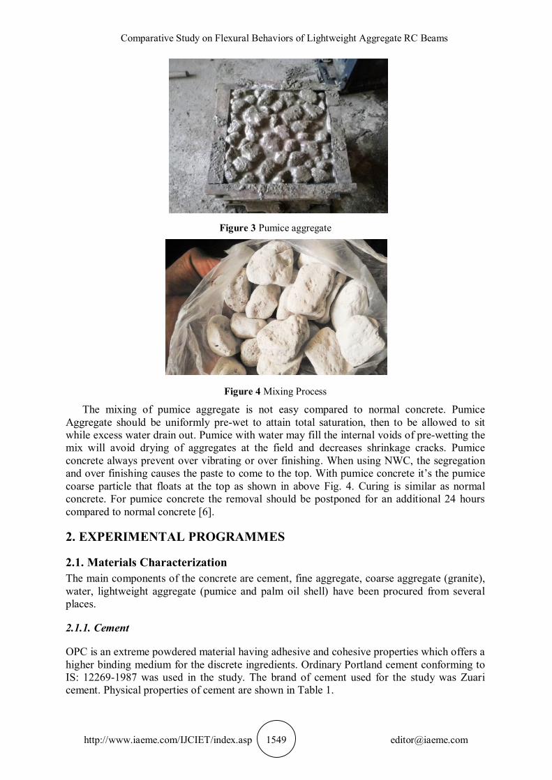
2.3. Test Beam Details A total of 10 under-reinforced beams were designed, cast and tested. Five beams of size 150×150×1000 mm and remaining five beams were in size 150×300×1000 mother effective span of simply-supported beams were 900 mm and 20mm clear cover were provided for the reinforced concrete beams. The geometry details of beam are shown in Fig. 5. In the test specimens, high yield deformed metal bars of diameter 16 mm, 12 mm and 8 mm have been used as longitudinal reinforcement. Two legged vertical stirrups of 8 mm diameter at a spacing of 300 mm for 150 mm deep beam and 210 mm for 300 mm deep beam center to center were provided as shear reinforcement. Associated with the beam test, the required quantity of cubes was examined on the same day as the beam testing to regulate the properties of the concrete. The width (B) and effective depth (d) of the beams were kept at 150 mm and 116 mm for five beams and 150 mm and 266 mm for remaining beams respectively. The beam length and sizes were taken to safeguard the beams that could fail under flexure (shear span to actual depth ratio) [10]. The beam sizes were also adequately large to follow actual structural components.
Figure 5 Geometry details of test beams
2.4. Preparation of Test Beams The Standard wooden beam moulds were used for casting of beams. i.e.150 × 150 × 1000 mm, 150 × 300 × 1000 mm. The moulds were tightly fitted. The inner side of the moulds was thoroughly oiled before going for concreting. The mix proportions were thoroughly mixed. The prepared concrete was placed in the moulds and it is compacted by means of manual
K. Harish Kumar and Dr. P. Polu Raju
http://www.iaeme.com/IJCIET/index.asp 1552 [email protected]
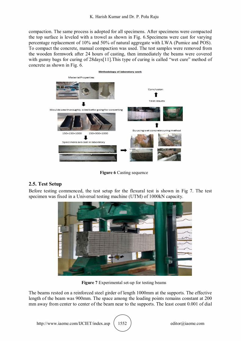
compaction. The same process is adopted for all specimens. After specimens were compacted the top surface is leveled with a trowel as shown in Fig. 6.Specimens were cast for varying percentage replacement of 10% and 50% of natural aggregate with LWA (Pumice and POS). To compact the concrete, manual compaction was used. The test samples were removed from the wooden formwork after 24 hours of casting, then immediately the beams were covered with gunny bags for curing of 28days[11].This type of curing is called “wet cure” method of concrete as shown in Fig. 6.
Figure 6 Casting sequence
2.5. Test Setup Before testing commenced, the test setup for the flexural test is shown in Fig 7. The test specimen was fixed in a Universal testing machine (UTM) of 1000kN capacity.
Figure 7 Experimental set-up for testing beams
The beams rested on a reinforced steel girder of length 1000mm at the supports. The effective length of the beam was 900mm. The space among the loading points remains constant at 200 mm away from center to center of the beam near to the supports. The least count 0.001 of dial

Comparative Study on Flexural Behaviors of Lightweight Aggregate RC Beams
http://www.iaeme.com/IJCIET/index.asp 1553 [email protected]
gauges were used for determining the deflection. At different loads dial gauge readings were recorded. Across the mid span depth and load points of the beam was instrumented to record the strain profile. The load was applied until first crack was observed at intervals of 2.5kN.Subsequently; with an increment of 5kN the load was applied. Strain values and deflections were recorded until failure with respective to load increments. The behavior of the beams was carefully observed, failure mode of the beam was recorded and development of cracks was observed [11].
3. TEST RESULTS AND DISCUSSION All beams confirmed to typical structural behavior in flexure. No horizontal cracks were determined at the level of reinforcement, which shows that there were no existences of bond failure. In maximum moment area, zigzag cracks were detected and final failure happened due to the significant amount of ultimate deflection with crushing of compression concrete. When maximum load was reached, a compression zone of concrete cover began to spall [11].
3.1. Rebound Hammer Test Rebound hammer also named as Schmidt hammer that is normally used for testing the quality of hardened concrete in a structure. It is a nondestructive and hand held testing device as shown in Fig. 8. It could be used on the hard-concrete surfaces, but strict procedures must be followed. In this study, the tests were conducted at the age of 28 days under water wet curing. The quality of the LWA concrete produced according to Table 4.
Figure 8 Testing quality of hardened concrete with rebound hammer
Table 4: Quality of LWAC with NDT
3.2. Compressive Strength In Fig. 9 and Fig. 10, it can be witnessed that all type of concrete elements was gained strength until 28 days. The concrete with 10% POS and Pumice replacement exhibited the
Lightweight aggregates
(LWA)
Percentage replacement of C.A, N/mm2 Depth 150 mm Depth 300 mm
0% 10% 50% 0% 10% 50% POS 19.7 23.1 20.5 20.6 29.3 25.1
Pumice 18 21.8 18.5 21.8 25.8 22.2

K. Harish Kumar and Dr. P. Polu Raju
http://www.iaeme.com/IJCIET/index.asp 1554 [email protected]
best strength which is over 33 MPa and 32 MPa only 5.25 MPa, 6.25MPa lesser than the control. Comparing to control, pumice and palm oil shell also gives the better strength.
Figure 9 Compressive strength at 28 days
Figure 10 Compressive strength at 28 days
3.3. Flexure Strength
3.3.1. Load-Deflection Behaviors The defection is one of the main criteria for the serviceability requirements of a structural member. The typical load-deflection curves for LWAC and NWC beam specimens with varying depths are shown in Fig. 11 & Fig. 12. The maximum load achieved for both LWAC. (Pumice and POS) and NWC specimens of depth 150mm is 45.11 kN, 75.51 kN and 70.6 kN, similarly maximum load for specimens of depth 300 mm is 63.74 kN, 191.72 kN and 111.79 kN with maximum deflection about respectively. Based on these results it is found that the ultimate load for NWCbeams is almost similar to LWAC beams.LWC (POS and Pumice) beams with 50% replacement tend to have greater deflection at lower load failure compared to the NWC specimens. This phenomenon is well agreed that material with lower elasticity modulus would deform more than the stiffer material [12].
38.233.2
30.1
38.2
3229.7
0
10
20
30
40
0 10 50
Com
pres
sive
sten
gth
N/m
m2
% Replacement of LWA
POS PA
10
15
20
25
30
35
40
0 5 10 15 20 25 30 35 40 45 50
Com
pres
sive
stre
ngh
in M
Pa
Replace of coarse aggregate with Pumice and POS in %
POS 3daysPOS 7daysPOS 28daysPumice 3 daysPumice 7dayspumice 28 days

Comparative Study on Flexural Behaviors of Lightweight Aggregate RC Beams
http://www.iaeme.com/IJCIET/index.asp 1555 [email protected]
Figure 11 Applied load vs Deflection of beam depth 150 mm
Figure 12 Applied load vs Deflection of beams depth 300 mm
3.3.2. Cracking Behaviors Comparing the pattern of the crack line between the normal weight and lightweight aggregate specimens, it shows that for lightweight aggregate specimens the crack line spread smoothly and almost linear during the load increment as shown in Fig. 13. This is due to the softer and weaker properties of LWA. In contrast, for normal weight specimens which have stronger aggregate, the crack lines always propagated in a form of jagged line and take an appreciable time to develop [13].
0
10
20
30
40
50
60
70
80
0 0.5 1 1.5 2 2.5 3 3.5 4 4.5
App
lied
Load
(kN
)
Mid-Span Deflection (mm)
Control MixPOS-10%POS-50%PA-10%PA-50%
0
20
40
60
80
100
120
140
0 0.25 0.5 0.75 1 1.25 1.5 1.75 2
App
lied
load
(kN
)
Mid-span Deflection (mm)
Control MixPOS-10%POS-50%PA-10%PA-50%

K. Harish Kumar and Dr. P. Polu Raju
http://www.iaeme.com/IJCIET/index.asp 1556 [email protected]
Figure 13 Crack pattern
During loading of the beam no vertical cracks are occurred in the beam and this imply there is no bond failure. During testing, it is found that in all beam specimen’s cracks tend to appear earlier in lightweight (Pumice) beam specimens. This indicates that the LWAC beams have a lower cracking load compared to the NWC beams. Formation of the initial crack for normal concrete and its comparison with LWAC are shown in Figs. 14 & 15
Figure 14 Comparison of normal concrete with 10% replacement of LWAC
Figure 15 Comparison of normal concrete with 50% replacement of LWAC
62.76
99.04
71.5
198.1
43.5855.4
0
25
50
75
100
125
150
175
200
App
lied
Load
(kN
)
Beams
Control specimen_150mmControl specimen_300mmPOS_150mmPOS_300mmPA_150mmPA_300mm
62.76
99.04
43.03
132.38
40.8253
0
20
40
60
80
100
120
140
160
App
lied
Load
(kN
)
Beams
Control specimen_150mmControl specimen_300mmPOS_150mmPOS_300mmPA_150mmPA_300mm

Comparative Study on Flexural Behaviors of Lightweight Aggregate RC Beams
http://www.iaeme.com/IJCIET/index.asp 1557 [email protected]
3.3.3. Determination of ultimate load The ultimate load of RC beams test was conducted on 150×150×1000 mm and 150×300×1000mm beams cast by M30 grade.
Figure 16 Test results of ultimate load for control and LWA beams of depth 150mm
The reinforcements were designed and detailed in graphs; the beams were tested for its ultimate load applying two-point load. Fig. 16 and Fig. 17 show the graph between ultimate moments vs. deflection of different depths.
Figure 17 Test results of ultimate load for control and LWA beams of depth 300 mm
Test results were showed in graphs of Figure. 18 and Figure. 19 between ultimate loads vs. deflection.
0
0.0002
0.0004
0.0006
0.0008
0.001
0.0012
0.0014
0.0016
0.0018
0.002M
u/fC
Kbd
2 (1
03 )
Δ (mm)
Control MixPOS-10%POS-50%PA-10%PA-50%
Mu/f
ckbd
2 (1
03 )
Δ (mm)
Control Mix
POS-10%
POS-50%
PA-10%
PA-50%

K. Harish Kumar and Dr. P. Polu Raju
http://www.iaeme.com/IJCIET/index.asp 1558 [email protected]
Figure 18 Test results for beam depth 150mm
Figure 19 Test results for beam depth 300mm
3.3.4. Moment curvature Relations
Figure 20 M – Ø relation for LWA beams of depth 150mm
0
0.00002
0.00004
0.00006
0.00008
0.0001
0 1 2 3 4 5
P U/f C
Kbd
(103 )
Δ (mm)
Control MixPOS-10%POS-50%PA-10%PA-50%
0
0.01
0.02
0.03
0.04
0.05
0.06
0.07
0.08
0.09
0.1
0 0.25 0.5 0.75 1 1.25 1.5 1.75 2
P u/f c
kbd(
103 )
Δ (mm)
Control MixPOS-10%POS-50%PA-10%PA-50%
0
2
4
6
8
10
12
14
16
0 0.0001 0.0002 0.0003 0.0004 0.0005 0.0006 0.0007
MU
(kN
-m)
Curvature in radians
Control Mix
POS-10%POS-50%
PA-10%
PA-50%

Comparative Study on Flexural Behaviors of Lightweight Aggregate RC Beams
http://www.iaeme.com/IJCIET/index.asp 1559 [email protected]
There are two approaches for curvature at mid-span from sectional analysis i.e. 1)Area moment theorem and 2) Linear strain distribution
Figure 21 M–Ø relation for LWA beams of depth 300mm
3.3.5. Ductility Index
Table 5 Test results in flexure and ductility index
S. No
Beam Designation First cracking load (δy, kN)
Ultimate load (δu, kN)
Ductility index (µ)
1 Control Mix-150mm 62.76 70.6 1.12 2 Control Mix-300mm 99.04 111.79 1.12 3 POS 10%-150mm 71.5 75.51 1 4 POS 50%-150mm 43.03 45.12 1.04 5 POS 10%-300mm 198.1 191.22 0.96 6 POS 50%-300mm 132.38 145.13 1.09 7 PA 10%-150mm 43.58 45.11 1.03 8 PA 50%-150mm 40.82 45.12 1.1 9 PA 10%-300mm 55.4 63.74 1.15 10 PA 50%-300mm 53 60.8 1.14 The ability of the structure to absorb energy and deform continuously without failure is
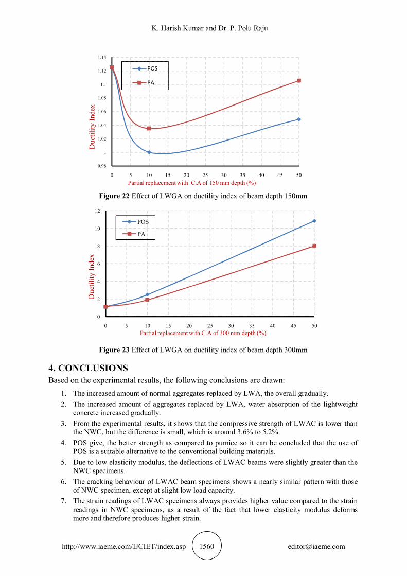
called Ductility. Ductility of the structure mainly depends on the materials used, which experiences lot of deformation before failure of structure. Proper detailing of structural elements in a structure enhances the width of the hysteresis’s loop (energy absorption capacity). In a ductile material failure plane makes a 450 angle with respect to major principle axis. Ductility Index (µ) is defined as the ration of ultimate deformation to yield deformation [15]. Ductility index increased when lightweight aggregates increased from 0% to 50% as per Table 5. From Figs. 21 and 22 shows that ductility index value increases when lightweight aggregate percent increases.
0
1
2
3
4
5
6
0 0.0001 0.0002 0.0003 0.0004 0.0005 0.0006 0.0007
Mu
(kN
-m)
Curvature in radians
Control Mix
POS-10%POS-50%
PA-10%PA-50%
K. Harish Kumar and Dr. P. Polu Raju
http://www.iaeme.com/IJCIET/index.asp 1560 [email protected]
Figure 22 Effect of LWGA on ductility index of beam depth 150mm
Figure 23 Effect of LWGA on ductility index of beam depth 300mm
4. CONCLUSIONS Based on the experimental results, the following conclusions are drawn:
1. The increased amount of normal aggregates replaced by LWA, the overall gradually. 2. The increased amount of aggregates replaced by LWA, water absorption of the lightweight
concrete increased gradually. 3. From the experimental results, it shows that the compressive strength of LWAC is lower than
the NWC, but the difference is small, which is around 3.6% to 5.2%. 4. POS give, the better strength as compared to pumice so it can be concluded that the use of
POS is a suitable alternative to the conventional building materials. 5. Due to low elasticity modulus, the deflections of LWAC beams were slightly greater than the
NWC specimens. 6. The cracking behaviour of LWAC beam specimens shows a nearly similar pattern with those
of NWC specimen, except at slight low load capacity. 7. The strain readings of LWAC specimens always provides higher value compared to the strain
readings in NWC specimens, as a result of the fact that lower elasticity modulus deforms more and therefore produces higher strain.
0.98
1
1.02
1.04
1.06
1.08
1.1
1.12
1.14
0 5 10 15 20 25 30 35 40 45 50
Duc
tility
Inde
x
Partial replacement with C.A of 150 mm depth (%)
POS
PA
0
2
4
6
8
10
12
0 5 10 15 20 25 30 35 40 45 50
Duc
tility
Inde
x
Partial replacement with C.A of 300 mm depth (%)
POS
PA

Comparative Study on Flexural Behaviors of Lightweight Aggregate RC Beams
http://www.iaeme.com/IJCIET/index.asp 1561 [email protected]
REFERENCES
[1] T. Parhizkar, M. Najimi, and A.R Pourkhorshidi “Application of Pumice Aggregate in Structural Lightweight Concrete”, Asian Journal of Civil Engineering, Vol. 13, no. 1, pp. 43-54, 2011.
[2] N. Manguriu, G.N. Mutku, O. Raphael, O. Walter, and O.A. Silvestre, “Properties of Pumice Lightweight Aggregate”, Civil and Environmental Research, Vol. 2, no.10, pp. 58-67, 2012.
[3] A. M. Neville, “Properties of Concrete”, Addison Wesley Longman Ltd, Essex, England, 2008.
[4] P. Shafigh, U.J. Alengaram, H.B. Mahmud and M.Z. Jumaat, “Engineering Properties of Oil Palm Shell Lightweight Concrete Containing Fly Ash”, Elsevier, Vol. 49, pp. 613-621, 2013.
[5] T.K. Mon, “Performance of Concrete with Uncrushed Palm Oil Shell as Coarse Aggregate”, Faculty of Civil Engineering Universiti Teknologi Malaysia, 2012.
[6] S. Rajeswari and S. George “Experimental Study of Light Weight Concrete by Partial Replacement of Coarse Aggregate Using Pumice Aggregate”, International Journal of Scientific Engineering and Research, Vol.4, no. 5, pp. 50-53, 2015.
[7] IS 516:1959, “Method of Tests for Strength of concrete”, Bureau of Indian Standard, New Delhi.
[8] IS 10262:2009, “Indian Standard, recommended guidelines for concrete mix designs”, Bureau of Indian Standard, New Delhi.
[9] IS 456: 2000, “Indian Standard, Plane and reinforced Concrete-Code of practice”, Bureau of Indian Standard, New Delhi.
[10] C.L.T. Delsye, M.A. Mannan and J.V. Kurian, “Flexural Behaviour of Reinforced Lightweight Concrete Beams made with Oil Palm Shell (OPS)”, Journal of Advanced Concrete Technology Vol. 4, no. 3, pp.1-10, 2006.
[11] W. Omar, R.N. Mohamed “The Performance of Pre-Tensioned Pre-Stressed Concrete Beams Made with Lightweight Concrete”, Journal of Civil Engineering, Vol.14, no.1, pp.60-70, 2002.
[12] M.M.H. Khan, L.G. Wei, T.J. Deepak, S. Nair, “Use of Oil Palm Shell as Replacement of Coarse Aggregate for Investigating Properties of Concrete”, International Journal of Applied Engineering Research, Vol. 11, pp. 2379-2383, 2016.
[13] S. Palani “Flexural Behaviour of Reinforced Beam Made with Light Weight Aggregate Concrete”, International Journal of Innovative Research in Science, Engineering and Technology, Vol. 4, no. 6, pp.1751-1755, 2015.
[14] J.K. Dattatreya, NP. Rajamane, D. Sabitha, P.S. Ambily, and MC. Nataraja, “Flexural Behaviour of Reinforced Geo-Polymer Concrete Beams”, International Journal of Civil and Structural Engineering, Vol. 2, no.1, pp. 138-159, 2011.
[15] A. Sofi and B.R.P. Kumar “An Experimental Investigation on Flexural Behaviour of Fiber Reinforced Pond Ash-Modified Concrete”, Ain Shams Engineering Journal no. 6, pp.1133-1142, 2015.