COMPARATIVE STUDY OF THREE DIFFERENT … · COMPARATIVE STUDY OF THREE DIFFERENT...
13
IJRRAS 18 (2) ● February 2014 www.arpapress.com/Volumes/Vol18Issue2/IJRRAS_18_2_02.pdf 109 COMPARATIVE STUDY OF THREE DIFFERENT ADSORBENT- ADSORBATE WORKING PAIRS FOR A WASTE HEAT DRIVEN ADSORPTION AIR CONDITIONING SYSTEM BASED ON SIMULATION 1 H. R. Ramji, 2 S. L. Leo, 1 I. A. W. Tan & 1 M. O. Abdullah 1 Faculty of Engineering, Universiti Malaysia Sarawak, 94300 Kota Samarahan, East Malaysia 2 International College of Advanced Technology Sarawak (ICATS), Jalan Canna, Off Jalan Wan Alwi, Tabuan Jaya, 93350 Kuching, East Malaysia E-mail: [email protected] ; [email protected] ABSTRACT In a previous study, a laboratory prototype of a thermal-driven adsorption air conditioning system employing activated carbon as adsorbent and methanol as the refrigerant was successfully developed. The experimental results employing the prototype obtained a COP of 0.19 and cooling capacity Q of around 320 kJ. The cooling power P yielded ~ 0.64 kW and it was able to produce chilled air temperature T chill,out of around 22 °C. In the present study, further works are conducted via simulation to carry out “what -if” analysis viz. to determine the optimal adsorbent- adsorbate working pair based on the prototype. Three types of refrigerants, coupled with activated carbon, were considered in this study, namely (1) methanol (similar to the experimental works); (2) ammonia; and (3) water. The simulation results obtained showed that activated carbon-water pair produced the best cooling compared to activated carbon-methanol and activated carbon-ammonia working pairs, as far as present study is concerned. The methanol and ammonia showed a COP of 0.37 and 0.4, respectively. The average T chill,out produced by methanol was around 15 °C while the temperature produced by ammonia was slightly higher around 19 °C. The cooling capacity P for methanol and ammonia showed a value of 0.65 kW and 0.50 kW, respectively. Activated carbon-water pair simulated to yield a higher COP of 0.58 with Q at 480 kJ mainly due to high heat of evaporation, which was able to produce average T chill,out of 12 °C with cooling power of approximately 1 kW. Keywords: Adsorption air conditioning system; Activated carbon; COP; Cooling power; Simulation; Waste heat. 1. INTRODUCTION The recent European Union directive on mobile air conditioning (MAC) phases out system using HFC-134a as refrigerant on the EU market from 2008 onwards (Reference). This leads to other alternative systems such as adsorption air conditioning system. Air conditioning technology is required to evolve due to the new environmental regulations which are concerning about the depletion of the ozone layer thus causing global warming. As a result, this trend has led to a strong demand for a new air conditioning technology (see e.g. Leo SL, Abdullah MO, 2009) [1]. As far as automobiles are concerned, unfortunately, no working adsorption cooling system has been practically run due to various restrictions - in particular due to sizing and cooling capacity limitations (Abdullah et al, 2011) [2]. There were several prototypes of adsorption refrigeration systems reported in literature, most of which were for ice making industry and others were designed for air conditioning purposes. Wang et al. (2001) [3] have reviewed an adsorption refrigerator driven with a heat source temperature of 100 °C. The refrigerator could obtain specific refrigeration power for 5.2 kg-ice /day per kg activated carbon with SCP of 150 W/kg adsorbent and a COP close to 0.5. In another study done by Wang et al. (2001) [3] on adsorption solar ice maker, 5-7 kg-ice/day per square meter solar collector could be produced continuously in well lighted condition, making use of solar energy. Meanwhile Tso et al. (2012) [4] had developed a chiller system powered by waste heat employing activated carbon- sodium silicate/calcium chloride. The outcome was chilled water temperature of 9 °C utilizing waste heat temperature of 85 °C as driving source. A COP and SCP of 0.65 and 380 W/kg-adsorbent were obtained respectively in their study. The corresponding adsorption-desorption cycle time of the operation showed that one full cycle could be completed optimally in 360 seconds. Xia et al. (2009) [5] had performed an analysis on an adsorption chiller employing silica gel-water pair with a methanol evaporator for cooling purposes. They obtained a COP of 0.39 with the heat source temperature of 82.5 °C, cooling water temperature of 30.4 °C and the temperature of the chilled water produced was 12 °C. Meanwhile, Sato et al. (1997) [6] had presented a multiple-stage adsorption air conditioning system for vehicles. Although the efficiency of the multiple-stage adsorption system was improved, the size of the system also increased
-
Upload
duongkhanh -
Category
Documents
-
view
214 -
download
0
Transcript of COMPARATIVE STUDY OF THREE DIFFERENT … · COMPARATIVE STUDY OF THREE DIFFERENT...
IJRRAS 18 (2) ● February 2014 www.arpapress.com/Volumes/Vol18Issue2/IJRRAS_18_2_02.pdf
109
COMPARATIVE STUDY OF THREE DIFFERENT ADSORBENT-
ADSORBATE WORKING PAIRS FOR A WASTE HEAT DRIVEN
ADSORPTION AIR CONDITIONING SYSTEM BASED ON SIMULATION
1H. R. Ramji,
2S. L. Leo,
1I. A. W. Tan &
1M. O. Abdullah
1Faculty of Engineering, Universiti Malaysia Sarawak, 94300 Kota Samarahan, East Malaysia
2 International College of Advanced Technology Sarawak (ICATS), Jalan Canna, Off Jalan Wan Alwi, Tabuan Jaya,
93350 Kuching, East Malaysia
E-mail: [email protected] ; [email protected]
ABSTRACT
In a previous study, a laboratory prototype of a thermal-driven adsorption air conditioning system employing
activated carbon as adsorbent and methanol as the refrigerant was successfully developed. The experimental results
employing the prototype obtained a COP of 0.19 and cooling capacity Q of around 320 kJ. The cooling power P
yielded ~ 0.64 kW and it was able to produce chilled air temperature Tchill,out of around 22 °C. In the present study,
further works are conducted via simulation to carry out “what-if” analysis viz. to determine the optimal adsorbent-
adsorbate working pair based on the prototype. Three types of refrigerants, coupled with activated carbon, were
considered in this study, namely (1) methanol (similar to the experimental works); (2) ammonia; and (3) water. The
simulation results obtained showed that activated carbon-water pair produced the best cooling compared to activated
carbon-methanol and activated carbon-ammonia working pairs, as far as present study is concerned. The methanol
and ammonia showed a COP of 0.37 and 0.4, respectively. The average Tchill,out produced by methanol was around
15 °C while the temperature produced by ammonia was slightly higher around 19 °C. The cooling capacity P for
methanol and ammonia showed a value of 0.65 kW and 0.50 kW, respectively. Activated carbon-water pair
simulated to yield a higher COP of 0.58 with Q at 480 kJ mainly due to high heat of evaporation, which was able to
produce average Tchill,out of 12 °C with cooling power of approximately 1 kW.
Keywords: Adsorption air conditioning system; Activated carbon; COP; Cooling power; Simulation; Waste heat.
1. INTRODUCTION
The recent European Union directive on mobile air conditioning (MAC) phases out system using HFC-134a as
refrigerant on the EU market from 2008 onwards (Reference). This leads to other alternative systems such as
adsorption air conditioning system. Air conditioning technology is required to evolve due to the new environmental
regulations which are concerning about the depletion of the ozone layer thus causing global warming. As a result,
this trend has led to a strong demand for a new air conditioning technology (see e.g. Leo SL, Abdullah MO, 2009)
[1]. As far as automobiles are concerned, unfortunately, no working adsorption cooling system has been practically
run due to various restrictions - in particular due to sizing and cooling capacity limitations (Abdullah et al, 2011) [2].
There were several prototypes of adsorption refrigeration systems reported in literature, most of which were for ice
making industry and others were designed for air conditioning purposes. Wang et al. (2001) [3] have reviewed an
adsorption refrigerator driven with a heat source temperature of 100 °C. The refrigerator could obtain specific
refrigeration power for 5.2 kg-ice /day per kg activated carbon with SCP of 150 W/kg adsorbent and a COP close to
0.5. In another study done by Wang et al. (2001) [3] on adsorption solar ice maker, 5-7 kg-ice/day per square meter
solar collector could be produced continuously in well lighted condition, making use of solar energy.
Meanwhile Tso et al. (2012) [4] had developed a chiller system powered by waste heat employing activated carbon-
sodium silicate/calcium chloride. The outcome was chilled water temperature of 9 °C utilizing waste heat
temperature of 85 °C as driving source. A COP and SCP of 0.65 and 380 W/kg-adsorbent were obtained
respectively in their study. The corresponding adsorption-desorption cycle time of the operation showed that one full
cycle could be completed optimally in 360 seconds.
Xia et al. (2009) [5] had performed an analysis on an adsorption chiller employing silica gel-water pair with a
methanol evaporator for cooling purposes. They obtained a COP of 0.39 with the heat source temperature of 82.5
°C, cooling water temperature of 30.4 °C and the temperature of the chilled water produced was 12 °C.
Meanwhile, Sato et al. (1997) [6] had presented a multiple-stage adsorption air conditioning system for vehicles.
Although the efficiency of the multiple-stage adsorption system was improved, the size of the system also increased
IJRRAS 18 (2) ● February 2014 Ramji & al. ● Comparative Study of Three Different Adsorbent
110
and its control system became more complex. Zhang et al. (2000) [7] had described an experimental intermittent
adsorption cooling system driven by the waste heat of a diesel engine. Zeolite 13X-water was used as the working
pair and a finned double-tube heat exchanger was used as the adsorber. The COP and specific cooling power (SCP)
of the system was 0.38 and 25.7 W/kg, respectively. Wang et al, (2001) [8] had studied an adsorption air
conditioning for a bus driven by waste heat from exhausted gases. The working pair for this system was activated
carbon and ammonia with the cooling power of 2.58 kW and a COP of 0.16. The activated carbon was pressurized
to a density of about 900 kg/m3 to fit additional adsorbent into the adsorber. The total weight of the two adsorbers
was about 248 kg and occupied about 1.0 m2.
In another research by Lu et al, (2004) [9] it was presented in experimental studies on the practical performance of
an adsorption air conditioning system powered by exhausted heat from a diesel locomotive. The system was
incorporated with one adsorbent bed and utilized zeolite and water as a working pair to provide chilled water for
conditioning the air in the driver’s cab of the locomotive. Their experimental results showed that the adsorption
system was technically feasible and could be applied for space air conditioning. Under typical running conditions,
the average refrigeration power ranging from 3.0 to 4.2 kW has been obtained. However, this system might not be
suitable for automobile application due to its size and high regenerative temperature.
According to Leo and Abdullah (2009) [1] for their research findings on automobile adsorption application, the COP
obtained through experimentation was approximately 0.19. Theoretically the value was quite small compared to
regular air conditioning available in the market. In spite of this, the value of specific cooling power recorded was a
promising 396.6 W/kg. With a cycle time set at 20 minutes, the average chilled air produced was around 22.6 °C.
The prototype operated intermittently between two adsorbers in order to retain the chilled air along the 20 °C
temperature line. Being able to produce this degree of air conditioning, the cooling coil temperatures could fall to a
range of 9.5 °C to 14.7 °C.
Now, this paper is a continuation of study by Leo & Abdullah et al, (2009) [1] and Abdullah et al, (2011) [2] on
adsorption cooling system. In previous papers, the authors had discussed the basic prototype design and conducted
several relevant experimentation works. In this paper, however, extended simulation works by CFD are presented;
ways to achieve better performance and minimize unnecessary energy losses are also discussed herewith. In
attaining the specified condition and cooling performance, subsequently, a comparative study was carried out based
on three working pairs (utilizing activated carbon as adsorbent) where methanol, ammonia, and water were
employed as the adsorbate (or refrigerant) in the adsorption air conditioning system. By varying these different
pairs, the corresponding variables such adsorption rate, heat transfers and operating cycle time were obtained.
Subsequently, performance parameters such as cooling power, P; cooling capacity, Q; and COP for all the three
working pairs were also modeled, simulated and analyzed.
2. EXPERIMENTAL SYSTEM SETUP AND DESCRIPTIONS
In this laboratory scale settings, a four stroke Subaru Robin 5.0 Hp powered engine was used to supply high
temperature fume gas. The exhaust gas produced by this engine could easily reach temperature of minimum 150 °C.
The engine was able to release a range of 150 °C – 200 °C of fume gas temperature. This prototype comprised of
two identical adsorbers placed side by side, a condenser, an evaporator, and three cooling fans.
The operation of the adsorption air conditioning system is a periodic succession of adsorption and desorption
processes. When the adsorbent is heated up in the first adsorber, the refrigerant vapour is desorbed and later
condensed in the condenser, and the condensed liquid is then transferred to the evaporator. The refrigerant vapour is
readsorbed by the adsorbent in the second adsorber in the cool down process. The cooling down process is assisted
by three cooling fans placed at their designated locations. The schematic diagram of the prototype during operation
is given in Figure 1.

IJRRAS 18 (2) ● February 2014 Ramji & al. ● Comparative Study of Three Different Adsorbent
111
Fig. 1 The prototype schematic during operation [10]
In this prototype, the adsorber was designed to intensify the heat and mass transfer of the adsorbent bed and
maximize the quantity of activated carbon to be packed. The adsorber had a length of 40 cm, a width of 20 cm and a
height of 10 cm. The refrigerant fluid flew through the internal channels of the tubes. A total of 1.6 kg of oil palm
shell derived granular activated carbon was packed between the fins of the tubes. The particle size of the activated
carbon was <3.0 mm, with surface area of 1000–1100 m2/g, total pore volume of 0.5–0.6 cm
3/g, density of 0.431
g/cm3 and iodine number of 1180. The heat of adsorption of the activated carbon was 1800 kJ/kg.
Air finned tube aluminum heat exchangers were used as the condenser and the evaporator. Though for the
evaporator a hanging type was chosen to provide better cooling instead. These heat exchangers were attached with a
12V dc fan to increase the heat rejection rate to the surrounding and thus increasing the cooling effect. The
evaporator that served as the heat absorption component was used to remove heat from the space and also
dehumidification. The moisture contained in the air condensed at the evaporator coil as the warmer air travelled
through the coil.
The temperature of the heat exchanging fluid was measured at the entrance and the exit of the condenser and
evaporator. The temperatures of the overall system and surrounding area were observed through thermal couples and
thermal camera. Along side the temperature, pressures were also measured in the adsorber, condenser and the
evaporator.
Figure 2 shows the placement and integration of the components in the prototype, which consists of two adsorbers, a
blower, an evaporator attached to two blowers, a condenser attached to a fan, an expansion valve, four check valves,
three three-way valves, an engine, and several pipe connectors. The detail design of the complete system was given
in the work of (Abdullah and Leo 2008) [10].
Fig. 2 The experimental rig [10]

IJRRAS 18 (2) ● February 2014 Ramji & al. ● Comparative Study of Three Different Adsorbent
112
This prototype generally worked in two main phases, i.e. desorption phase and adsorption phase. Practically the
cooling effect was due to the adsorption process; while desorption on the other hand worked as pre-cooling in the
operation as to prepare the adsorbent for the adsorption process. Throughout this process, desorption and adsorption
had to work continuously in a suitable time limit which was often referred to as time cycle. Hence, to achieve this
condition, an intermittent operation was designed whereby two adsorbers of same design were used. The idea was
that whenever one of the adsorber was undergoing adsorption, the second adsorber would undergo desorption.
Through this scheme, a continuous cooling could be provided by this system.
3. PHYSICAL AND MATHEMATICAL MODEL
3.1 The adsorber
The Dubinin-Astakhov (D-A) equation that relates the concentration and temperature is represented in the form of
(Lu et al. 2004) [9];
n
sT
Tkxx 1exp0 (1)
Where x, represents the concentration of methanol adsorbed in bed at the temperature of the adsorption, T. Ts
represents the saturated temperature in the adsorber with given pressure, P. The saturated adsorption capacity of the
working pair is given by xo. The parameter k and n are constants that vary with different working pair.
3.2 Mass and energy balance equation
3.2.1 Adsorption rate
The adsorption process in this system could be divided into two phases which were desorption (regeneration) phase
and also the adsorption phase. In this system, these two identically design adsorbers would be operating
intermittently with each other. The cycle time would rely heavily on the adsorption and desorption rate of the system
as given in the equations by Tso et al. (2012) [4];
Adsorption:
)( , adseqadsads
ads xxKdt
dx
(2)
)exp()( ,,, tKxxxx adsoadseqadseqadsads (3)
Desorption:
)( desdes
des xKdt
dx
(4)
)exp()( ,,, tKxxxx desodeseqdeseqdesdes (5)
3.2.2 Condenser and evaporator model
In modeling the condenser and evaporator, several assumptions have been considered as following,
1. The working fluid was considered always in thermodynamic equilibrium corresponding to its saturation
conditions.
2. The saturated temperature depended on the internal pressure of the working equipments given by Antoine
equation with parameter as shown in Table 1 [11].
3. The refrigerant contained inside the adsorbent was completely desorbed before shifting to adsorption phase.
4. the entire refrigerant fluid flow rate coming from the condenser was instantly evaporated. There would be
no fluid lost in between the processes. Every amount of refrigerant desorbed in the first adsorber would be
transferred in completion to the next adsorber where adsorption took place.
This means;
acdesref mxm (6)

IJRRAS 18 (2) ● February 2014 Ramji & al. ● Comparative Study of Three Different Adsorbent
113
Table 1. Antoine equation for givn refrigerants
Compounds Temperature range (oC) A B C
Methanol (-20-140) 7.87863 1473.11 230
Ammonia (-83-60) 7.55466 1002.711 247.885
Water (0-150) 7.96681 1668.21 228
While employing the usual energy equation, the total heat power input to the system including the condenser and
evaporator models can be presented as below:
Total heat power input )( ,,, outeginegegpeg TTCmP
(7)
Condenser )()( ,,, inoutairpairrefvconddesrefpref TTcmhTTcm
(8)
Evaporator )()( ,,, outinairpairevcondrefprefrefv TTcmTTcmh
(9)
3.3 System performance parameters
3.3.1 Cooling power and cooling capacity
The cooling output readings of the prototype via experiment were calculated from measuring the temperature
difference of the inlet and outlet of the chilled air by its flow rate and specific heat (Lu et al. 2004) [9];.
outchillinchillairpchill TTcmP ,,,exp (10)
The total cooling capacity would be:
dtPQc expexp, (11)
While in simulation, cooling power could be obtained theoretically by:
evcondrefprefvreftheoc TTcqmQ ,,, (12)
Hence, the total cooling capacity could be presented as;
evcondrefprefv
cyc
ref
theo TTcqt
mp ,,
2/1
(13)
Where qv,ref is the heat of evaporation for methanol, and tcyc1/2 is the half cycle time of the whole operation.
3.3.2 Coefficient of performance (COP) and specific cooling power (SCP)
The performance of the adsorption cooling system is commonly evaluated using two performance factors; the
coefficient of performance (COP) and specific cooling power (SCP). In general, COP is the amount of cooling
produced by an adsorption cooling system per unit heat supplied [9] as shown:
in
ev
Q
QCOP
(14)
The SCP, on the other hand, is defined as the ratio between the cooling production and the cycle time per unit of
adsorbent weight, as given below [1]:
ac
ev
m
QSCP
(15)
Since SCP relates to both the mass of adsorbent and the cooling power, it reflects the size of the system. For a
nominal cooling load, higher SCP values indicate the compactness of the system.
IJRRAS 18 (2) ● February 2014 Ramji & al. ● Comparative Study of Three Different Adsorbent
114
3.4 Governing equations
In simulation, fluid flow modeling described by Siegal and Howel (1992) [12] had been utilized to solve the classic
Navier-Stokes equations by superimposing thousands of grid cells which describe the physical geometry of the air
flow and heat transfer, ie;
Svdt
d (16)
The transport equations for mass conservation, momentum and energy for any system are given in these generic
equations (Siegal and Howel (1992) [12], Abdullah et al. (2006) [13]:
Continuity:
0i
i
dx
ud
dt
d
(17)
Momentum:
i
ij
i
jii
dx
d
dt
dP
dx
vvd
dt
vd
(18)
Energy:
iii
P
i
Pdx
dp
dt
dp
dx
dTk
dx
dTc
dx
dTc
dt
d
(19)
The simultaneous equations were solved iteratively for each one of the cells to produce a solution which satisfied the
conservation law of mass, momentum and energy.
In a previous study, we had considered double adsorber prototype design and reported the associated simulation
works [16]; while in the current study, a three different adsober/adsorbent working pairs were being investigated.
4. SIMULATION RESULTS AND ANALYSIS
During the heating process, refrigerant was desorbed and pressurized from the adsorber. Simultaneously, the
adsorber was initially prepared to contain 45 %, 26 % and 29 % of methanol, ammonia and water, respectively (in
accordance to Eq.(1)). Theoretically, the more refrigerant were desorbed, the more cooling effect could be produced.
Equivalently, the ability of refrigerant to be squeezed out of the adsorbent bed would indicate the effectiveness of
the heat transfer processes of the system.
In Fig. 3 (a), the diagram illustrates the early condition of the adsorber when the activated carbon and refrigerant
were at room temperature around 30 °C. Once the exhaust gas had entered the area, the heat of the exhaust gas
vaporized the refrigerant within the activated carbon. The pressurized refrigerant would be released from the
adsorber due to pressure difference, thus making its way to the evaporator. In this condition the adsorber was in
desorption process. While in Fig. 3 (b), the adsorption process took place at the same time but on the second
adsorber desorption took place. The diagram shows that the source of heat was from the refrigerant and activated
carbon side. This heat was transferred to the cool air blown by the blower to hasten the cool down process.

IJRRAS 18 (2) ● February 2014 Ramji & al. ● Comparative Study of Three Different Adsorbent
115
Fig. 3 Simplified (a) desorption and; (b) adsorption mechanism that occurs inside the adsorber. The circles represent
the activated carbon granular. The shaded region indicates the refrigerant.
The ratio between adsorbate and adsorbent in this system was set according to Eq. (1) provide. It was to be noted
that an excess amount of adsorbate could cause over saturation of activated carbon that could lead to reduction of
system performance (e.g. see Leo and Abdullah, 2009) [1].
4.1 Adsorption isobar
In Fig. 4 the adsorption isobars for the respective working pairs are presented. The saturated temperature, Ts used
were corresponding to the saturated pressure, Ps that were utilized in experimental works by Leo and Abdullah
(2009) [1]. In this result Ts implemented was 45 °C. This indicated that the operating pressure of the adsorber would
depend on the adsorbate used. The saturated pressure Ps was 0.09, 0.5 and 18 bar for activated carbon-methanol,
activated carbon-water and activated carbon-ammonia pair, respectively. The parameters for the DA-equation for
each of the working pairs are given in Table 2 [14].
Fig. 4 Adsorption isobar capacity for respective working pair (ac= activated carbon)
50 100 1500
0.25
0.5
Temperature (°C)
Co
ncen
trati
on
(k
g/k
g)
ac−met
ac−ammo
ac−water
From blower
refrigerant (v)
Activated Carbon
Hot Air
Adsorbed
refrigerant (l)
Heat absorbed Air
Ambient
b)
Desorbed
refrigerant (v)
Activated Carbon
Ambient
Refrigerant (l)
Heat absorbed Exhaust gas
From engine
a)

IJRRAS 18 (2) ● February 2014 Ramji & al. ● Comparative Study of Three Different Adsorbent
116
Table 2 D-A equation constant values for appointed working pair [13]
Working pair k x0 n
Activated carbon - methanol 13.38 0.45 1.5
Activated carbon - ammonia 3.57 0.29 1.38
Activated carbon - water 5.36 0.26 1.73
4.2 Adsorbate concentration, xdes against time, t.
The graphs in Fig. 5 were plotted to show the relationship of refrigerant concentration in the adsorber, xdes during
desorption phase against time, t. In this particular simulation setting, a constant exhaust gas inlet temperature, Teg,in
of 200 °C was used as the heat energy source. Desorption temperature; Tdes was identified to be below 150 °C
throughout the process for all the working pairs.
Fig. 5 Concentration of refrigerant during desorption phase, xdes against time, t for respective working pair (Teg,in =
200 °C)
The results showed that activated carbon-ammonia working pair had the shortest desorption time (around 420 sec)
followed by water (480 sec) and methanol (600 sec). This could be explained by the volatility of the refrigerant
used. In comparison, ammonia was the most volatile compound used then methanol and water when arranged in
decreasing volatility. Methanol took longer time than water to be desorbed because of greater initial concentration,
xo in the adsorber.
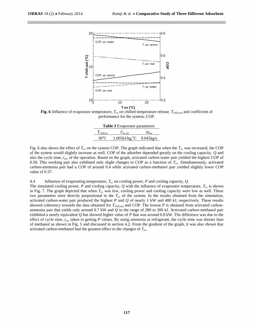
4.3 Influence of evaporating temperature, Tev on chill temperature release, Tchill,out and COP
Fig. 6 shows the simulated chilled temperature release, Tchill,out and COP of the system at different evaporating
temperatures, Tev. According to Fig. 6, Tchill,out was lower at higher Tev and it applied to all the refrigerants used. In
this graph, it shows that activated carbon-water working pair produced the lowest Tchill,out in the range of 12 to 13°C.
This was followed by methanol and ammonia that achieved Tchill,out of 15 to 17°C and 18 to 20°C, respectively. This
implied that activated carbon-water provided the best cooling profile. The results obtained were based on the
evaporator parameters given in Table 3.
0 300 600 9000
0.2
0.4
Time (s)
Co
ncen
trati
on
(kg
/kg
)
ac−met
ac−ammo
ac−water
IJRRAS 18 (2) ● February 2014 Ramji & al. ● Comparative Study of Three Different Adsorbent
117
Fig. 6 Influence of evaporator temperature, Tev on chilled temperature release, Tchill,out and coefficient of
performance for the system, COP.
Table 3 Evaporator parameters
Tchill,in Cp, air mair
30oC 1.005kJ/kg.
oC 0.045kg/s
Fig. 6 also shows the effect of Tev on the system COP. The graph indicated that when the Tev was increased, the COP
of the system would slightly increase as well. COP of the adsorber depended greatly on the cooling capacity, Q and
also the cycle time, tcyc of the operation. Based on the graph, activated carbon-water pair yielded the highest COP of
0.58. This working pair also exhibited only slight changes to COP as a function of Tev. Simultaneously, activated
carbon-ammonia pair had a COP of around 0.4 while activated carbon-methanol pair yielded slightly lower COP
value of 0.37.
4.4 Influence of evaporating temperature, Tev on cooling power, P and cooling capacity, Q.
The simulated cooling power, P and cooling capacity, Q with the influence of evaporator temperature, Tev is shown
in Fig. 7. The graph depicted that when Tev was low, cooling power and cooling capacity were low as well. These
two parameters were directly proportional to the Tev of the system. In the results obtained from the simulation,
activated carbon-water pair produced the highest P and Q of nearly 1 kW and 480 kJ, respectively. These results
showed coherency towards the data obtained for Tchill,out and COP. The lowest P is obtained from activated carbon-
ammonia pair that yields only around 0.7 kW and Q in the range of 280 to 300 kJ. Activated carbon-methanol pair
exhibited a nearly equivalent Q but showed higher value of P that was around 0.8 kW. The difference was due to the
effect of cycle time, tcyc taken in getting P values. By using ammonia as refrigerant, the cycle time was shorter than
of methanol as shown in Fig. 5 and discussed in section 4.2. From the gradient of the graph, it was also shown that
activated carbon-methanol had the greatest effect to the changes of Tev.
0 10 2010
15
20
0.3
0.4
0.5
0.6
T ev (°C)
T c
hil
l,o
ut
(°C
)C
OP
COP, ac−met
T, ac−met
T, ac−water
COP, ac−water
COP, ac−ammo
T, ac−ammo

IJRRAS 18 (2) ● February 2014 Ramji & al. ● Comparative Study of Three Different Adsorbent
118
Fig. 7 Influence of evaporator temperature, Tev on cooling power, P and cooling capacity, Q.
4.5 Chilled temperature released, Tchill,out and cooling power, P of the adsorber against time, t
Fig. 8 shows the plot of chilled temperature released, Tchill,out by the evaporator as a function of time, t. The graph
depicted that in comparison of the three refrigerants used, water was able to produce the lowest Tchill,out. It was
considered here that lower Tchill,out was more favorable in this system. By using water as refrigerant, Tchill,out produced
could be down to 12°C whereas methanol and ammonia could produce Tchill,out around 15 °C and 19 °C,
respectively.
Fig. 8 Chilled temperature release, Tchill,out by the evaporator against time, t for respective working pair.
In Fig. 9, the simulated cooling power, P of each working pair is plotted against time, t. It was in coherence with the
results shown in Fig. 8, in which activated carbon-water exhibited the highest P of up to 0.80 kW. It was followed
by activated carbon-methanol pair that produced P at around 0.65 kW and activated carbon-ammonia pair at 0.50
kW. Based on the results shown in both Figs 8 and 9, it could be concluded that this was due to the different values
in the heat of vaporization of the refrigerant, Hv. In comparison, water possessed the highest Hv followed by
methanol and ammonia.
0 10 200.6
0.8
1
300
400
500
T ev (°C)
Q (k
J)
P (
kW
)
P, ac−met
Q, ac−met
Q, ac−ammo
P, ac−ammo
P, ac−water
Q, ac−water
0 600 1200 180010
20
30
T c
hil
l,o
ut
(°C
)
Time (s)
ac−met
ac−water
ac−ammo

IJRRAS 18 (2) ● February 2014 Ramji & al. ● Comparative Study of Three Different Adsorbent
119
Fig. 9 Cooling power, P against time, t for the respective working pair.
5. DISCUSSIONS
In the adsorption refrigeration system, working pairs are the most crucial part to be considered. According to Wang
et al. (2010) [15] explaining the basic principle and working characteristics of the adsorption refrigeration system,
the adsorbent should have the characteristics of;
1. large adsorption capacity
2. large change of adsorption capacity with temperature variation
3. flat desorption isotherm
4. good compatibility with refrigerant
Similarly in vapor compression refrigeration system, refrigerant should exhibit the quality of;
1. large latent heat per volume
2. right freezing point and saturation vapour pressure
3. good thermal stability
Based on the given criteria, the working pairs for adsorption system were decided. Currently there are no working
pairs that completely meet the requirements mentioned. But the commonly used working pairs closely meet these
conditions [15]. Therefore, the working pairs such as activated carbon-methanol, activated carbon-ammonia and
activated carbon-water were tested in the adsorption system designed by Leo and Abdullah (2009) [1] for real life
implementation. After careful selection of the suitable working pairs guided by the prerequisite as listed in the
preceding paragraph extracted from Wang et al. (2010) [15], the performance parameters simulated in the present
study are now summarized in Table 4. The results showed that activated carbon–water pair had given the most
desirable results with the best cooling in terms of COP, cooling power, cycle time and average chilled temperature.
Table 4 Comparison of adsorber performance for the three working pairs utilizing different adsorbents
Adsorbent/Refrigerant Methanol(Exp) Methanol(Sim) Ammonia Water
Mass of adsorbent, mref (g) 360 360 230 210
Cycle time, tcyc (s) 1200 1200 840 960
Average chilled temperature produce, Tchill,out (oC) 22 15 19 12
Cooling power, P (kW) 0.64 0.65 0.50 0.98
Cooling capacity, Q (kJ) 320 390 210 480
Coefficient of performance, COP 0.19 0.37 0.40 0.58
0 600 1200 18000
0.2
0.4
0.6
0.8
Co
oli
ng
Po
we
r (k
W)
Time (s)
ac−met
ac−water
ac−ammo

IJRRAS 18 (2) ● February 2014 Ramji & al. ● Comparative Study of Three Different Adsorbent
120
6. CONCLUSIONS
Based on the simulation results, it was found that activated carbon-water working pair would be the preferred
adsorbent-adsorbate to be utilized in this adsorption air conditioning system. The activated carbon-water pair
produced the optimal cooling compared to methanol and ammonia as far as the range of parameters in the study was
concerned. The methanol and ammonia showed a COP of 0.37 and 0.4, respectively. Tchill,out produced by methanol
was around 15 °C while the value produced by ammonia was slightly higher around 19 °C. The cooling capacity, P
for methanol and ammonia showed a value of 0.65 kW and 0.50 kW, respectively. Meanwhile, activated carbon-
water pair yielded a COP of 0.58 with Q at 480 kJ. This system was able to produce Tchill,out of 12 °C with cooling
power of approximately 1kW.
7. REFRENCES
[1]. S.L. Leo, M.O. Abdullah. Experimental study of an automobile exhaust heat-driven adsorption air-
conditioning laboratory prototype by using palm activated carbon-methanol. HVAC&R Res 16(2) (2010)
221-231.
[2]. M.O. Abdullah, I.A.W. Tan, S.L. Leo. Automobile adsorption air-conditioning system using oil palm
biomass-based activated carbon: A review. Renew. Sust. Energy Rev. 15 (2011) 2061-2072.
[3]. R.Z. Wang. Adsorption refrigeration research in Shanghai Jiao Tong University. Renew Sust. Energy Rev. 5
(2001) 1-37
[4]. C.Y. Tso, C.Y.H. Chao, S.C. Fu. Performance analysis of a waste heat driven activated carbon composite
adsorbent–water adsorption chiller using simulation model. Int. J. of Heat and Mass Transfer 55 (2012) 7596-
7610
[5]. Z.Z. Xia, R.Z. Wang, D.C. Wang, Y.L. Liu, J.Y. Wu, C.J. Chen. Development and comparison of two-bed
silica gel-water adsorption chillers driven by low grade heat source, Int. J. Therm. Sci. 48 (2009) 1017-1025
[6]. H. Sato, S. Honda, H. Tanaka, T. Terao. Adsorptive type refrigeration apparatus. US patent 5619866 (1997).
[7]. L.Z. Zhang. Design and testing of a waste heat adsorption cooling system. Appl. Therm. Eng. 20(1) (2000)
103-114
[8]. R.Z. Wang, W. Wang, T.F. Qu. Research and development on waste heat driven adsorption bus air
conditioning system. Final Report SJTU-UTRC Joint Reserch Program, Shanghai Jiao Tong University
(SJTU) and United Technologies Research Center (UTRC), China (2001)
[9]. Y.Z. Lu, R.Z. Wang, M. Zhang, S. Jiangzhou. Adsorption cold storage system system with zeolite-water
working pair used for locomotive air conditioning. Energy Convers Manage. 44(10) (2003) 1733-1743
[10]. M.O. Abdullah, S.L. Leo. Heat driven adsorption air-conditioning system for automobile. Malaysian Patent
Number: PI20081641; MY-143033-A (2009)
[11]. R.M. Felder, R.W. Rousseau. Elementary Principles of Chemical Processes, third ed., John Wiley & Sons,
Inc. 2000, pp 640-641
[12]. R. Siegal, J.R. Howel. Thermal Radiation Heat Transfer, third ed., Hemispher, New York, 1992 (Chapter 7).
[13]. M.O. Abdullah, F.A. Mikie, C.Y. Lam. Drying performance and thermal transient study with solar radiation
supplemented by force-ventilation. Int. J. of Therm. Sci. 45 (2006) 1027-1034
[14]. A.C. Deshpande, R.M. Pillai. Adsorption air conditioning (AdAC) for automobiles using waste heat
recovered from exhaust gases. 2nd
Int. Conference on Emerging Trends in Eng. and Tech. (2009) ICETET-09
IEEE 19-24
[15]. D.C. Wang, Y.H. Li, D. Li, Y.Z. Xia, J.P. Zhang. A review on adsorption refrigeration technology and
adsorption deterioration in physical adsorption systems. Renew. Sust. Energy Rev. 14 (2010) 344-353
[16]. HR Ramji, SL Leo, MO Abdullah. Parametric study and simulation of a heat-driven adsorber for air
conditioning system employing activated carbon–methanol working pair
Applied Energy, 113, 324–333, http://dx.doi.org/10.1016/j.apenergy.2013.07.017.

IJRRAS 18 (2) ● February 2014 Ramji & al. ● Comparative Study of Three Different Adsorbent
121
NOMENCLATURE
A cross sectional area (m2)
Alm log mean area
Cp specific heat capacity (Jkg-1
K-1
)
COP coefficient of performance
h convective coefficient
k constant in Dubinin equation
m mass (kg)
P cooling Power (kW)
Q cooling capacity (kJ)
qv vaporization heat
SCP specific cooling power
T temperature (°C)
t time (s)
x concentration (kgkg-1
)
xo initial concentration (kgkg-1
)
Subscript
ac activated carbon
ads adsorption
cyc1/2 half cycle
eg exhaust gas
exp experimental
des desorption phase
ev evaporator
i inside
o outside
ref refrigerant (methanol)
s saturated
v vaporization
Superscript
n constant in Dubinin equation
ACKNOWLEDGEMENT
This present study was supported by the Ministry of Higher Education, Malaysia under Prototype Development
Research Grant Scheme (PRGS), Contract No: PRGS/1/11/TK/UNIMAS/02/01. The authors would like to thank all
staff for their continuous encouragements throughout this project.