Comparative Study of the Performance of High-Speed Gas … · · 2011-05-14Final report Contract...
53
Final report Contract number : FA5209-05-P-0234 Comparative Study of the Performance of High-Speed Gas Bearings for Micro-Turbo Machines Submitted to Asian Office of Aerospace Research & Development (AOARD) Program manager Dr. Brett Pokines February 20 th , 2006 By Shin-ichi Togo Professor Mechanical Engineering Department Tohoku-Gakuin University 13-3 Chuo 1-chome, Tagajo-shi Miyagi-ken, 985-8537, Japan [email protected]
Transcript of Comparative Study of the Performance of High-Speed Gas … · · 2011-05-14Final report Contract...

Final report
Contract number : FA5209-05-P-0234
Comparative Study of the Performance of
High-Speed Gas Bearings for Micro-Turbo Machines
Submitted to
Asian Office of Aerospace Research & Development (AOARD) Program manager Dr. Brett Pokines
February 20th, 2006
By
Shin-ichi Togo Professor
Mechanical Engineering Department Tohoku-Gakuin University
13-3 Chuo 1-chome, Tagajo-shi Miyagi-ken, 985-8537, Japan

Report Documentation Page Form ApprovedOMB No. 0704-0188
Public reporting burden for the collection of information is estimated to average 1 hour per response, including the time for reviewing instructions, searching existing data sources, gathering andmaintaining the data needed, and completing and reviewing the collection of information. Send comments regarding this burden estimate or any other aspect of this collection of information,including suggestions for reducing this burden, to Washington Headquarters Services, Directorate for Information Operations and Reports, 1215 Jefferson Davis Highway, Suite 1204, ArlingtonVA 22202-4302. Respondents should be aware that notwithstanding any other provision of law, no person shall be subject to a penalty for failing to comply with a collection of information if itdoes not display a currently valid OMB control number.
1. REPORT DATE 07 NOV 2007 2. REPORT TYPE
3. DATES COVERED
4. TITLE AND SUBTITLE Comparative Studies of the Performance of High-Speed Gas Bearings forMicro Turbo Machines
5a. CONTRACT NUMBER FA520905P0234
5b. GRANT NUMBER
5c. PROGRAM ELEMENT NUMBER
6. AUTHOR(S) Shinichi Togo
5d. PROJECT NUMBER
5e. TASK NUMBER
5f. WORK UNIT NUMBER
7. PERFORMING ORGANIZATION NAME(S) AND ADDRESS(ES) Tohoku-Gakuin University,13-1 Chou 1-Chome, Tagajo-shi,Miyagi-ken,985-8537 985-8537,Miyagi,JP,985-8537
8. PERFORMING ORGANIZATIONREPORT NUMBER N/A
9. SPONSORING/MONITORING AGENCY NAME(S) AND ADDRESS(ES) 10. SPONSOR/MONITOR’S ACRONYM(S)
11. SPONSOR/MONITOR’S REPORT NUMBER(S)
12. DISTRIBUTION/AVAILABILITY STATEMENT Approved for public release; distribution unlimited.
13. SUPPLEMENTARY NOTES
14. ABSTRACT Developed micromachine gas turbine generator for robotics & man-portable power sources operation atultra-high speed (870,000rpm for 10mm compressor). Developed Hydrodynamic Herringbone/Spiralgroove bearing to reach design speed and completed test on performance.
15. SUBJECT TERMS
16. SECURITY CLASSIFICATION OF: 17. LIMITATION OF ABSTRACT
18. NUMBEROF PAGES
12
19a. NAME OFRESPONSIBLE PERSON
a. REPORT unclassified
b. ABSTRACT unclassified
c. THIS PAGE unclassified
Standard Form 298 (Rev. 8-98) Prescribed by ANSI Std Z39-18

1
Executive Summary
The objective of the research is to realize micro-high-speed bearings to stably run a 4mm diameter shaft of the rotordynamic configuration equivalent to that with 10mm diameter centrifugal compressor and turbine at its both end, at a speed higher than 870,000 rpm that is required for the 100W class micro-gas turbine.
In previous research contract, a micro-bearing tester had been developed, and 770,000 rpm had been achieved by hydroinertia gas bearings, but could not reach 870,000 rpm. The maximum speed was limited by whirl instability. Hence, methods to enhance the anti-whirl stability of micro-hydroinertia gas bearings have been studied.
To increase the stably operable limit of the rotor, the effect of bearing clearance, supply gas pressure, the non-uniformity of the journal bearing supply gas pressure, and the effect of the length to diameter ratio (L/D) have been tested. The supply gas pressure (Figure 13) and the bearing clearance (Figure 14) have been shown to have large effects on the anti-whirl stability. The L/D of the journal bearings (Figure 15) and the circumferential non-uniformity of the supply gas pressure (Figure 17) have also been shown to have stabilizing effect, although the effect was not large as expected. The reason for the effect being small is study by CFD analysis. The results showed significantly smaller pressure anisotropy generated in the bearing clearance than the pressure difference of the two supply air pressures in orthogonal
Fig.13 Effect of the supply air pressure of the bearings
0.8
0.9
1
1.1
1.2
400 500 600 700
Supply gas pressure [kPa]
Relative Speed
Thrust bearingsJournal bearingsTheory
Fig.14 The effect of the thrust bearing clearance
600000
700000
800000
900000
1000000
10 15 20 25
Thrust Bearing Clearance��[�m]
Maximum Achieved Speed [rpm]
.
Fig.17 The effect of non-uniform journal bearing supply gas pressure
(Pthrust=700kPa, Pjournal_high=500kPa)
870000
880000
890000
900000
0 100 200 300 400 500 600
Lower Side Journal Pressure [KPa]
Maximum
Achieved Speed [rpm
].
600000
700000
800000
900000
1000000
0.5 0.6 0.7 0.8 0.9 1 1.1L/D
Maximum
Achieved Speed [rpm
]
Theory(incompressible)
Test results
Fig.15 The effect of L/D of the journal
bearing

2
direction (Figure 26). The pressure anisotropy provided by the non-uniform supply gas pressure is found to diminish rapidly unless the L/D is very small. For the bearings with not-small L/D, other methods should be studied to provide the anisotropic pressure field inside the bearing clearance.
By selecting appropriate combination of bearing clearances, supply gas pressure and its pressure anisotropy, and L/D, maximum rotor speed of 891,000 rpm has been achieved. This is certainly the world record for a rotor configuration with 10mm 3-dimensional (non-MEMS) turbine at the end of the shaft. By these results, the feasibility of the bearing for a practical rotor configuration to realize a 100W class micromachine gas turbine has successfully been proven. (Figure 28)
The power required to operate hydroinertia gas bearings and hydrodynamic gas bearings are compareded based on the analysis and the micro-bearing test data. Although hydroinertia gas bearings has significantly smaller viscous loss than hydrodynamic gas bearings, the total power required to operate the bearings is significantly larger for hydroinertia gas bearings if the power required to generate the pressurized supply air is included. For a rotor for 100W gas turbine system, hydroinertia
0
10
20
30
40
700000
710000
720000
730000
740000
750000
760000
770000
780000
790000
800000
810000
820000
830000
840000
850000
860000
870000
880000
890000
900000
Rotor Speed [rpm]
Radial Amplitude [
Target Speed
Fig28. History of radial displacement on achieving the maximum
speed of 891,000 rpm
0.6
0.8
1
1.2
1.4
1.6
1.8
2
2.2
45 60 75 90 105 120 135
Circumferential Angle [deg]
Pressure [P/Pam
b]
4mm2.7mm1mm
P/Pamb=5.0-1.5
0
0.2
0.4
0.6
0.8
1
1.2
1.4
1.6
1.8
2
0 0.5 1 1.5 2 2.5 3 3.5 4 4.5
Bearing Length [mm]
Pressure Amplitude [P/Pam
b] P/Pamb=5.0-1.5
(a) Pressure Distribution
Fig.26 Effect of the bearing length on the pressure distribution
(pressure distribution averaged in x-direction)
(b) Pressure Amplitude

3
gas bearings require 303W, while hydrodynamic gas bearings require 68W, at the design condition. A power as large as 285W is consumed to generate the high pressure that is required to keep the stability of the hydroinertia gas bearings at high speed.
A set of self-acting Herringbone grooved and spiral grooved hydrodynamic gas bearings for 100W gas turbine rotor has been designed. The shaft diameter is increased to 6mm to make the fabrication easier, for the first try. The designed bearing clearances are 7.5μm for the journal bearing and 40μm(total clearance) for the thrust bearing, which seem to be practically feasible values. The bearings will be fabricated and tested in option-1 contract. At such small bearing clearance, the heat expansion effect will become critical. Hence, it is recommended to also conduct studies on hydrodynamic gas bearings with larger compliance, such as foil bearings.

4
Table of Contents 1. Introduction
1-1. New market for portable power generation 5 1-2. Remaining issues from the previous contract 8 1-3. Objectives of the work 9 1-4. Approach of the work 10
2. Experimental Setup 2-1. Micro-Bearing Tester 11 2-2. Test Facility and the Data Acquisition System 14 3. The Design of Micro-Hydroinertia Gas Bearings 16 4. Test Results 20 4-1. Effect of the Supply Gas Pressure 21 4-2. Effect of the Bearing Clearance 23 4-3. Effect of L/D 24 4-4. Effect of Circumferential Anisotropy of Journal Bearing Supply Gas Pressure 25 4-5. Analysis of the reasons for small pressure anisotropy and L/D effects 28 4-6. Maximum Rotor Speed 40 4-7. Power Requirements 42 5. Design of Hydrodynamic air bearings 44
5-1. Design of Herringbone-groove journal bearings 45 5-2. Design of Spiral-groove journal bearing 47
6. Summary 49 7. Remaining works 50
Reference 51

5
1. Introduction 1-1. New market for portable power generation Since after the MIT group started the research on micromachine gas turbine of shirt-button size
fabricated by MEMS (Microelectromechanical Systems) technology [1], researches on gas turbines at micro-scale are taking place at variety of place over the world mainly based on the technological interest of the researchers. Meanwhile, recent rapid advancement in autonomous robots and mobile electric equipments are requiring better mobile power source than batteries. Although, battery is a good power source for applications that require large current to power many servomotors, it has a weakness of low energy density that the operation time before recharging is short. These day’s humanoid robots can operate only about 30 minutes after half a day of battery recharging. This will largely limit the application of humanoid robots and mobile electric devices, and the improvement of the battery performance is desired. However, a lot of technology improvements have already been achieved over decades, and there is not much room left for the performance improvement of batteries. Hence, increase of the operable time will require proportional increase of battery weight, which in turn, requires more power. This will cause a snowball effect that makes the system large and heavy.
To increase the energy density to achieve long operable time, some people are expecting the development of fuel cells. Fuel cell is known for its high energy density and high thermal efficiency. However, it should be noted that the power density of the fuel cell is low. It can be used to power applications that require high voltage with small current, but it does not fit to power electric motors. Large current density causes significant drop of the efficiency in fuel cells. Recent intense effort of developing the fuel cell for automobiles may someday enable high power density fuel cell, but it will not be in the near future.
Fig.1 Various types of portable power sources and their applications
Pow
er D
ensi
ty, W
/kg
Energy Density, Wh/kg
Fuel Cells
Internal Combustion EnginesBatteries
Pow
er D
ensi
ty, W
/kg
Energy Density, Wh/kg
Fuel Cells
Internal Combustion EnginesBatteries

6
Power sources that have both high power density and high energy density are internal combustion engines as are shown in Figure 1. Among variety of internal combustion engines, the type that fits for micro-size power sources for autonomous robots would be the continuous rotation type without any friction seals and with continuous combustion, because the surface roughness, and therefore the friction loss, and the heat dissipation will become relatively large at micro-scale. One of such types of internal combustion engines is gas turbine. Gas turbine at micro-scale can be a good candidate for the power source for mobile machines.
Among numbers of technologies required to realize micro-turbo machines, the most important and at the same time the most difficult is to realize the stable rotation at high speed. Since the achievable pressure ratios of turbo compressors are a function of the circumferential velocity of the rotor tip, the rotational speed of the impeller is inversely proportional to the diameter of the compressor impeller. Hence, ultra-high-speed operation is required for a compressor for a gas turbine at micro-scale. The required rotational speed for an impeller of diameter 10mm will become as high as 870,000 rpm to achieve pressure ratio 3. If the shaft diameter is 4mm, which was in the case required from the structure, the DN number that is the typical measure for ball bearings becomes as high as 3,500,000, which is beyond the value that ball bearings can be used in today’s technology. Hence, gas bearings will be used. However, gas bearings have weakness of whirl instability at high speed. The hydrostatic gas bearings, which are the most popular type of gas bearings, are known to have the whirl instability speed at twice the resonance speed of the rotor in two dimensional typical section analysis. Previous study on whirl instability of various hydrodynamic gas bearings by Isomura et al. [2] showed that some small stably operable conditions exist for herringbone type and lobe type hydrodynamic gas bearings, but bearing clearance has to be as small as 3 to 4μm. This bearing clearance seems to be too small to be practical, because heat generated by the viscous shear flow in the small bearing clearance will cause heat expansion of the shaft and the bearings, and it would be difficult to maintain the required bearing clearance.
Hence, the candidates of gas bearings to be used for the micro-turbo machines are narrowed down to either foil bearings that has a compliancy, or hydroinertia gas bearings that has large bearing clearance and large anti-whirl stability. Hydroinertia gas bearings are a type of hydrostatic gas bearings with large bearing clearance. Although the construction of the both types of bearings are the same, hydroinertia gas bearings are known to have larger load capacity than usual hydrostatic gas bearings because the pressure on the both side of the bearings will not cancel each other. The supply gas flow in the larger side of the bearing clearance becomes supersonic when the rotor shift to one side of the bearing clearance, and the pressure in the larger side clearance becomes suction force. The whirl frequency of the hydroinertia gas bearings is known to be higher than that of hydrostatic gas bearings.
Since, foil bearings are studied extensively by specialists [3], but since hydroinertia gas bearings are not much studied, researches on hydroinertia gas bearings has been conducted by the authors, and the shaft speed as high as 770,000 rpm has been achieved [4][5], which is still 100,000 rpm short of the

7
speed required for the compressor to realize 100W class micromachine gas turbine. Hence, study on the methods to increase the stability of hydroinertia gas bearings has to be conducted.
To increase the stability of hydrostatic gas bearings, it is known that the choice of appropriate bearing clearance and the supply gas pressure are important. To increase the maximum achievable speed for 100,000 rpm to realize the target speed, it is necessary to acquire quantitative data to use in design. Hence, experimental verification of the stabilizing effect of these conventional methods is necessary.
In addition, variety of methods to increase the anti-whirl stability of hydrostatic gas bearings have been analyzed by Spakovszky et al. [6],[7], recently. Since hydroinertia gas bearings are a type of hydrostatic gas bearings, those methods are also applicable to hydroinertia gas bearings. However, the geometry of the bearings used by Spakovszky et at. [6],[7] are very special due to the limitation of MEMS fabrication, the effect of those methods may not work in the configuration we are developing. Hence, it will also be useful to conduct the experimental research to quantitatively verify these stabilizing effects.

8
1-2. Remaining issues from the previous contract (1) The condition that the pneumatic vibration occurs should be quantified, and the method to
avoid it should be established. (2) A method to increase the whirl stability of hydroinertia gas bearings should be established
based on the analysis with compressibility effect, and should be validated by achieving 870,000 rpm in micro-bearing test.
(3) The hydroinertia gas bearing test will be continued until 870,000 rpm is achieved. (4) The high precision fabrication methods will be studied to realize the required accuracy of the
bearing parts, repeatedly. (5) The study on hydrodynamic gas bearings will be continued to get more quantitative data to
compare with the hydroinertia gas bearings.

9
1-3 Objectives of the work (1) Experimentally confirm the effectiveness of various stabilizing techniques to enhance the
maximum achievable speed of the hydroinertia gas bearings against whirl instability. (2) Find a combination of the methods to achieve the stable operation at 870,000 rpm, which is the
rotor speed required for 100W class gas turbine with impeller diameter 10mm. (3) Develop herringbone bearings for micro-rotors.

10
1-4 Approach of the work (1) Using the micro-bearing tester developed in the last contract, perform micro-hydroinertia gas
bearing tests by changing the various design parameters, and check the change of stability limit. The effect of following design parameters will be studied.
Supply gas pressure of thrust bearings Supply gas pressure of journal bearings Bearing clearance of thrust bearing Bearing length Pressure anisotropy in journal bearings
(2) Applying combination of stability enhancing methods found in (1), run the rotor at a speed higher than 870,000rpm.
(3) Design and develop a herringbone bearing tester. The shaft diameter will be larger than 4mm for the first try to secure the fabrication accuracy.

11
2. Experimental Setup 2-1. Micro-Bearing Tester
A micro-bearing tester developed in the last contract has been used for the test. The cross sectional view of the micro-bearing tester is shown in Figure 2. Diameter of the journal bearings is 4mm, and the outer and inner diameters of the thrust bearings are 10mm and 5mm, respectively. The thrust disk is located at the center of the shaft. The rotor is driven by a radial turbine of diameter 10mm located at an end of the shaft. The compressor impeller of the original turbo compressor on the other end of the shaft is replaced by a cylindrical dummy compressor that simulates the weight and the moment of inertia of the original centrifugal compressor. The reason for replacing the compressor with a dummy compressor is to enable accurate displacement measurement in both radial and axial direction at the location of the compressor, using two miniature eddy current displacement sensors (AEC PU-03A) of diameter 3.1mm. The accurate displacement measurements allowed the rotor to operate under the whirl oscillation up to a certain specified amplitude. Note that the measurement position of the radial displacement is located outside of the two journal bearings. Hence, the measured amplitude of the radial displacement can be larger than the bearing clearance when the rotor is oscillating at conical mode. The rotational speed is measured by laser reflection probe. The rotor is made of Ti-6Al-4V and the surface of the shaft is covered with thickness 2μm of CrN ceramic coating. The rotor weighs 2.3g, and is balanced to the level that the residual unbalance is less than 0.1g-μm, which approximately corresponds to G=6 grade. The fabricated rotor is shown in Figure 3.
The bearing sleeves are made of ZrO2 ceramics. Each of both thrust and journal bearings has 8 air supply holes of diameter 0.3mm. Detail of the construction of the bearing tester is explained in the final report of the previous contract. Modifications made for the bearing tester in current contract are as follows. (1) The length of journal bearings is shortened from 4mm to 2.7mm which correspond to L/D=1 and
0.675, respectively. (2) The supply gas feeds of the journal bearings are modified from that explained in the previous report,
to add a capability to change the pressure of journal bearing supply gas for every 2 holes to provide pressure anisotropy as shown in Figure 4.
The micro-bearing tester installed in the test stand is shown in Figure 5.

12
10mm
Dummy CompressorThrust Disk
Dummy Compressor
Turbine
Ceramic Bearing Sleeves
Journal Bearings
Thrust Bearings
Displacement Sensor
Rotor Speed Sensor
Fig.2 Cross section of the micro-bearing tester
Fig.3 Rotor used for the micro-bearing test

13
Fig5. The micro-bearing tester at test setup
The Micro-bearin
Bearing gas control valves
Fig.4 Arrangement of anisotropic radial bearing supply pressure
2 orthogonal directions

14
2-2. Test Facility and the Data Acquisition System A new test facility has been prepared and provided by Tohoku University. The test facility is equipped
with a 22kW class screw compressor and air drafting system to have a capability to accommodate all the necessary tests to develop a 500W class micromachine gas turbine. The screw compressor provides the pressurized air to drive the turbine. The air drafting system is to provide fresh air to the compressor inlet, and discharge the high temperature exhaust gas to outside the building in future tests with compressor and combustor. The new test facility and the system diagram are shown in Figure 6.
The volume flow rate and the pressure of each bearing supply gas are measured, in addition to the rotor vibration measurement by eddy current displacement sensors on the bearing tester. The rotor speed is measured by a laser reflection type sensor (Philtec D-20). An 1/rev pulse is generated by the laser sensor by measuring a black mark on the rotor painted by a marker pen, and then by counting the number of the pulse by a pulse counter. The vibration data is sampled at 50 kHz, and Fourier converted to frequency domain data. Then the maximum amplitude and the frequency of the amplitude are tracked to get the evolution of the shaft vibration amplitude. All the flow rates, pressures, vibration amplitudes, and the speed data are sampled at 10Hz, and taken into the LabView real time monitoring and recording system. In addition, the vibration data are recorded by a separate high speed data sampling system at the sampling rate of 125 kHz to resolve the detailed phenomena in time domain, to be able to analyze in the case unexpected phenomenon occurred.

15
�PC �Data logger �AD Converter�Data recorder�Amplifier
�PC(LabView)
�Compressor �Air dryer
� Pressure �Air flow meter�Filter �Regulator
�Displacement detectors(Eddy current type)
Fig.6 The test facility and the test system
�
�
�
� �
� � � �
�
�
�
�
�
�
�
� �
�
�
�
�
�
�
�
�
�
16
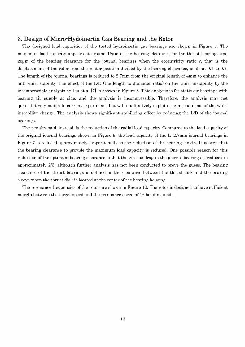
3. Design of Micro-Hydoinertia Gas Bearing and the Rotor The designed load capacities of the tested hydroinertia gas bearings are shown in Figure 7. The
maximum load capacity appears at around 18μm of the bearing clearance for the thrust bearings and 25μm of the bearing clearance for the journal bearings when the eccentricity ratio ε, that is the displacement of the rotor from the center position divided by the bearing clearance, is about 0.5 to 0.7. The length of the journal bearings is reduced to 2.7mm from the original length of 4mm to enhance the anti-whirl stability. The effect of the L/D (the length to diameter ratio) on the whirl instability by the incompressible analysis by Liu et al [7] is shown in Figure 8. This analysis is for static air bearings with bearing air supply at side, and the analysis is incompressible. Therefore, the analysis may not quantitatively match to current experiment, but will qualitatively explain the mechanisms of the whirl instability change. The analysis shows significant stabilizing effect by reducing the L/D of the journal bearings.
The penalty paid, instead, is the reduction of the radial load capacity. Compared to the load capacity of the original journal bearings shown in Figure 9, the load capacity of the L=2.7mm journal bearings in Figure 7 is reduced approximately proportionally to the reduction of the bearing length. It is seen that the bearing clearance to provide the maximum load capacity is reduced. One possible reason for this reduction of the optimum bearing clearance is that the viscous drag in the journal bearings is reduced to approximately 2/3, although further analysis has not been conducted to prove the guess. The bearing clearance of the thrust bearings is defined as the clearance between the thrust disk and the bearing sleeve when the thrust disk is located at the center of the bearing housing.
The resonance frequencies of the rotor are shown in Figure 10. The rotor is designed to have sufficient margin between the target speed and the resonance speed of 1st bending mode.

17
(a) Thrust bearing
Fig.7 Designed load capacity of the bearings
Thrust BearingPs = 300kPa
0
1
2
3
4
5
6
7
8
9
0 10 20 30 40 50 60
Bearing Clearance [μm]
Load
cap
acity
[N
]
0
5
10
15
20
25
30
Vol
ume
Flow
Rat
e [L
iter/m
in]
ε = 0.8
ε = 0.2
ε = 0.4
ε = 0.6
Flow Rate
(b) Journal bearings (L=2.7mm)
0
0.2
0.4
0.6
0.8
0 10 20 30 40 50Bearing clearance [μm]
Load
cap
acity
[N
]
0
4
8
12
16
Gas
flow
rate
(l/m
in)
ε = 0.5
ε = 0.3
ε = 0.1
D = 4 mmL = 2.7 mmn = 8P = 300 kPa

18
Radial BearingL=4mm, D=4mm
Ps = 0.3MPa
00.10.20.30.40.50.60.70.80.9
11.11.21.3
0 5 10 15 20 25 30 35 40 45
Bearing Radial Clearance [μm]
Load
Cap
acity
[N
]
012345678910111213
Vol
ume
Flow
Rat
e[L
itre/
min
]
ƒ Ã = 0.1ƒ Ã = 0.3ƒ Ã = 0.5Flow(L/ min)
Fig. 9 Load capacity of the original (L=4mm) journal bearings
0
1
2
3
4
5
6
7
8
9
10
0 50 100 150 200
Bearing Gap Cr [ƒ Ê‚ �]
Whirl Ra
L/D=0.1
L/D=0.25
L/D=0.5
L/D=1
forwardwhirl
backwardwhirl
Fig. 8 Effect of L/D on the whirl ratio based on the method by Spakovszky et al [4]

19
0
200000
400000
600000
800000
1000000
1200000
1400000
50 100 150 200
Bearing Stiffness��[kN/m]
1st&2nd mode Resonance Speed
[rpm
]
1st Bending
Target Speed
Cylindrical M ode
Conical M ode
Fig.10 Resonance speed of the tested rotor

20
4. Test Results The bearing test has conducted by monitoring the radial displacement of the rotor until the amplitude
exceeds certain limit. By setting a uniform limit, the stability of the bearings can quantitatively be compared by the rotor speed at the specified whirl amplitude. In most of the case the limit is set to 40μm. The axial position of the displacement measurement is not located between the two journal bearings, so the amplitude can be larger than the bearing clearance, if the rotor is oscillating at conical mode. The bearing clearance of the journal bearings is 30μm. The onset of the whirl oscillation can be seen from the time domain shaft vibration data, but the amplitude is very small at the onset and it is sometimes difficult to specify the onset. Also, the amplitude doesn’t diverge by increasing the rotor speed for while, so it is not practical to define the whirl onset as the operable limit, which is often considered as the operable limit. The operable limit is found as a point that the whirl amplitude suddenly starts growing rapidly by increasing the rotor speed, and is expected to crash by increasing a couple of thousands rpm more of the rotor speed. An example of such change of the whirl amplitude observed during the test is shown in Figure 11. To specify such points, the amplitude of 40μm has been selected as the operable limit after several trials.
10
15
20
25
30
35
40
45
0 100000 200000 300000 400000 500000 600000 700000 800000 900000Rotational speed (rpm)
Am
plitu
de (μ
m)
.
Pradial = 300 kPa, Paxial = 300 kPa
Pradial = 400 kPa, Paxial = 400 kPa
Pradial = 500 kPa, Paxial = 500 kPa
Pradial = 600 kPa, Paxial = 600 kPa
Peadial = 500 kPa, Paxial = 600 kPa
Hydroinertia air bearinghradial = 30 μmhaxial = 30 μmD = 4 mmL = 4 mm
Max 812000 rpm
300kPa700-500kPa
600kPa
500kPa
400kPa
600-500kPa
Fig.11 An example of the evolution of whirl amplitude

21
4-1. Effect of the Supply Gas Pressure The effect of the supply gas pressure has studied, first. The supply gas pressure of the thrust bearings
are changed from 400kPa to 700kPa, while keeping the journal bearing pressure to a constant condition. The journal bearing supply gas pressure is 500kPa and 200kPa for two orthogonal directions. The
600000
650000
700000
750000
800000
850000
900000
400 500 600 700Thrust Bearing Supply Gas Pressure�@[kPa]
Maximum Achieved Speed
Fig.12 Effect of the supply air pressure of the thrust bearings (Pjournal=500-200kPa)
Fig.13 Effect of the supply air pressure of the journal bearings
0.8
0.9
1
1.1
1.2
400 500 600 700
Supply gas pressure [kPa]
Relative Speed
Thrust bearingsJournal bearingsTheory

22
maximum achieved rotor speeds at each supply gas pressure of the thrust bearing are plotted in Figure 12. It is seen from the figure that the maximum achieved speed increases almost linear to the supply gas pressure of the thrust bearings. The increase of the supply gas pressure has a significant stabilizing effect on the maximum achievable speed. The speed is increased for approximately 25% from 680000 rpm to 840000 rpm when the supply gas pressure is increased for 50% from 400kPa to 600kPa. Hence, 0.5% of the maximum achieved speed increases for every percent of the thrust bearing supply pressure increase.
The effect of the supply gas is also tested for the journal bearings. The supply gas pressure of the journal bearings is set to 500kPa and 600kPa, while that of the thrust bearings is set to 600kPa. Since the bearing clearance is different from the data in Figure 12, the test results are shown in Figure 13 after being normalized by the value at 500kPa condition. In the figure, the theoretical result based on the incompressible analysis of the journal bearings by Liu et al. [7], and the test results of varying the thrust bearing pressure are also plotted. The test results of the journal bearings show a good match to the theoretical results, and also to the thrust bearing test results. It is shown that the thrust bearings and the journal bearings have almost the same rate of stabilizing effects in current rotor.

23
4-2. Effect of the Bearing Clearance Since the maximum achievable speed is affected by how much of the load due to the whirl oscillation
the bearing can hold, the bearing is expected to show higher maximum operable speed with larger load capacity condition if the whirl excitation energy is the same. The maximum achievable speed at various bearing clearance of the thrust bearings is shown in Figure 14. The figure shows that the thrust bearing clearance has large effect on the maximum achievable speed, and it can be seen that the bearing clearance to provide the highest operation speed matches to that to provide the largest load capacity at eccentricity ratio ε=0.6 at Figure 7(a). The data shows that the maximum achieved speed has its maximum value at the bearing clearance of approximately 15μm, and that approximately 10% increase of the maximum speed is obtained when the bearing clearance is reduced from 20μm to 15μm. From the design data of Figure 7(a), the thrust bearing is supposed to be generating approximately 20% increase of the load capacity. This is 0.5% of the maximum achievable speed increase for every percent of the load capacity increase. It is seen by comparing Figure 14 and 7(a) that the selection of the clearance of the thrust bearings has significant effect on the maximum achievable rotor speed.
This increase rate matches to that observed in bearing clearance test. The bearing clearance of the journal bearings is not easy to change. Hence, the effect of the bearing
clearance of the journal bearing could not be tested.
Fig.14 The effect of the thrust bearing clearance
600000
700000
800000
900000
1000000
10 15 20 25
Thrust Bearing Clearance��[�m]
Maximum
Achieved Speed [rpm
]
.

24
4-3. Effect of L/D From the incompressible analysis, the smaller bearing length to diameter ratio (L/D) is supposed to
provide higher stability against whirl. The test results show the same tendency as the analysis that the stability increases as the L/D is decreased, but with an order smaller effect. The results are shown in Figure 15. The condition of the supply gas pressure is 500 and 400kPa for the high pressure side and the low pressure side of the journal bearings, respectively. The pressure of the thrust bearings is 700kPa. This tendency of smaller effect than theory is just the same as that found in the section of the effect of the non-uniform supply gas pressure. The reduction of the bearing length is expected to have effect of increasing the circumferential non-uniformity of the pressure distribution in the bearing clearance, from the same distribution of the supply gas pressure. This effect will be checked by numerical simulations in future.
600000
700000
800000
900000
1000000
0.5 0.6 0.7 0.8 0.9 1 1.1L/D
Maximum
Achieved Speed [rpm
]
Theory(incompressible)
Test results
Fig.15 The effect of L/D of the journal bearing (Pthrust=700kPa, Pjournal=500&400kPa)

25
4-4. Effect of Circumferential Anisotropy of Journal Bearing Supply Gas Pressure
Due to the study by Liu et al [7], giving anisotropy to the supply gas pressure of journal bearings in two orthogonal direction will have a significant stabilizing effect. To check this effect, the supply gas pressure of the journal bearings is changed for every 2 supply gas holes out of 8 holes as shown in Figure 4. The pressure of thrust bearings is kept to 700kPa, and the high side pressure of the journal bearings is kept to 500kPa. Only the low side pressure of the journal bearing has been changed. The test results are shown in Figure 16. Increase of the maximum speed is seen by increasing the difference between the two pressures by reducing the low pressure of the journal bearings. However, the stabilizing effect has been found to be very small. The increase of the maximum speed by reducing the low side pressure from 500kPa to 150kPa is only 10,000 rpm, and the rotor became unstable when the low side pressure has further been reduced.
The theoretical results of the incompressible analysis by Liu et al.[7] are plotted in Figure 16 in comparison to the test data. The stability is increased in both cases by reducing the lower side pressure, but the trends are very different in two points. First, the maximum speed is only twice the cylindrical mode resonance frequency in the analysis, while the measured value is over 880,000 rpm when the journal supply pressure is uniform at 500kPa. Secondly, the gradient of the maximum achieved speed change is two orders smaller than that predicted by the incompressible analysis. The 10,000 rpm increase of the maximum speed is achieved by reducing the lower side journal bearing supply gas pressure from 500kPa to 150kPa in the test data, the same 10,000 rpm increase of the maximum speed is achieved by reducing the pressure for only 5kPa to 495kPa from 500kPa in the incompressible analysis.
A reason for the discrepancy at 500kPa is expected to be the compressibility effect. The analysis is the incompressible analysis at a two dimensional section, the whirl ratio at uniform supply gas pressure is always 2, and the shaft resonance speed is the cylindrical mode without rotor flexure. The hydroinertia gas bearings have a region of supersonic flow in the bearing clearance, and therefore, the flow is compressible. Also, the hydroinertia gas bearings are known to have whirl ratio larger than 2 even at uniform supply gas pressure due to the compressibility effect.
A possible reason of the over prediction by the theory at lower pressure is the possibility of pressure non-uniformity not being generated in the bearing gap as intended. If the bearing length is very short, the local pressure would be the supply gas pressure from the closest supply hole. However, current bearing has a bearing length of 2.7mm while the bearing diameter is 4mm. If the cylindrical surface of the journal bearing is expanded and suppose a supply gas hole is working up to the mid point between the adjacent supply gas holes, the width of the area that a hole is working is 1.57mm. Since the bearing length is 2.7mm, it can easily be understood that the high side pressure will influence over most of the bearing surface area. The pressure anisotropy will work fine when the bearing length is extremely short

26
that the pressure from the adjacent gas supply hole won’t have significant effect. Whether this guess is correct or not is checked by numerical simulations.
0
200000
400000
600000
800000
1000000
0 100 200 300 400 500 600
Radial bearing pressure, Pradial or Pradial, y (kPa)
Max
imum
sta
ble
rota
tiona
l spe
ed (r
pm)
Uniform pressurizationPthrust = 700 kPa
Cross pressurizationPradial, x = 500 kPaPthrust = 700 kPa
Fig.16 The effect of the anisotropic supply pressure of journal bearings on the maximum achieved rotor speed

27
Fig.18 Comparison of the non-uniform journal bearing supply air effect with the theory
(Pthrust=700kPa, Pjournal(high)=500kPa)
0
1000000
2000000
3000000
4000000
0 100 200 300 400 500 600Lower Side Journal Pressure [KPa]
Maximum Achieved Speed [rpm]
.
Theory(incompressible)
Test results
Fig.17 The effect of non-uniform journal bearing supply gas pressure
870000
880000
890000
900000
0 100 200 300 400 500 600
Lower Side Journal Pressure [KPa]
Maximum
Achieved Speed [rpm
].

28
4-5. Analysis of the reasons for small pressure anisotropy and L/D effects In previous 2 sections, the experimental results showed large discrepancy from the analysis. The effect of pressure anisotropy and the L/D on the whirl instability was significantly smaller than the incompressible analysis results by Liu et al [7]. One possible reason is that the analysis by Liu et al assumes a special configuration of static air bearings for MEMS rotor under development at MIT. It has very small L and the bearing pressure is supplied from one side of the bearing. The analysis assumes the bearing supply air flows straight in axial direction, and has no circumferential flow components. Hence, at each circumferential position, the pressure in the bearing gap is assumed to change linearly from supply pressure to ambient pressure without the effect of circumferentially adjacent section of the supply air flow.
In current bearing configuration, L is in the same order of magnitude to the diameter, and the bearing supply air is supplied from 8 circumferentially discrete supply air holes. The air in the bearing clearance initially flows radially outward from the supply air holes, and then turns to the direction of the bearing axis. Hence, the pressure distribution can totally be different from that modeled in Liu et al’s analysis.
To check this effect, CFD simulation of the flow inside the bearing clearance with anisotropic pressure supply has been performed for various low side supply air pressure and L/D, by steady viscous compressible calculations. The governing equations of the code are three-dimensional thin shear layer Navier-Stokes equations. The numerical fluxes for the convective terms are evaluated by the SHUS scheme (Simple High-resolution Upwind Scheme)[8], which is a family of the AUSM (Advanced Upstream Splitting Method)-type scheme [9], and is extended to higher-order by the MUSCL (Monotone Upstream-centered Schemes for Conservation Law) interpolation based on the primitive variables [10]. The LU-ADI (Lower-Upper Alternating Directional Implicit) factorized implicit algorithm is employed for the time integration [11]. The turbulence model by Spalart & Allmaras [12] has been used for all calculation domains. The rotor wall boundary is not moving.
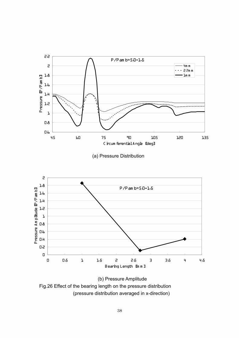
Circumferentially one quarter of the bearing clearance is calculated. A segment includes a high pressure port and a low pressure port. No bearing eccentricity is modeled, and uniform bearing clearance is assumed. The calculated circumferential pressure distribution at the center plain (the plain that contains supply air holes, x=L/2), the plain between the center plain and the bearing edge (x=L/4), and the area averaged pressure in x-direction are shown in Figure 19(a), (b), and (c), respectively. It is seen from the figure that the maximum pressure difference in the bearing clearance has reduced to 1/10, from approximately 0.4MPa (P/Pamb=4) to 0.04MPa (P/Pamb=0.4). The circumferential non-uniformity of the pressure in the area-averaged pressure is very small. The pressure distributions in Figure 20 show that the pressure at the outer half of the bearing is almost uniform in circumferential direction, due to the circumferentially uniform ambient pressure. The circumferential anisotropy generated by the supply air rapidly decays in axial direction. The pressure anisotropy is significant only in the plain containing the supply air holes.

29
2 more cases, a longer L (L=4mm) and a shorter L (L=1mm), are calculated. It is seen from Figure 21 and 22 that significant pressure anisotropy is seen only when the length L is very small. In addition to that the pressure anisotropy becomes significantly small at outside the plain containing the supply air holes as are shown in Figure 23 and 24, the pressure anisotropy at x=L/4 reduces almost inversely proportional to the bearing length L as shown in Figure 25. If the pressure is averaged out in x direction, the reduction rate of the effect of anisotropy is even larger. Since the first harmonics of the pressure anisotropy are the important measure to quantitatively compare the effect, the pressure amplitude of the first harmonics are calculated from the x-averaged pressure distribution at P/Pamb=5.0-1.5 shown in Figure 26(a). The results in Figure 26(b) shows that the pressure amplitude reduces to almost 1/10 by increasing the bearing length L from L/D=0.25 (L=1mm) to L/D=0.675 (L=2.7mm). The pressure amplitude shows minimum at L/D=0.675 (L=2.7mm) and this is seen from Figure 25(a) that the low pressure near the pressure supply hole due to high-speed supply air flow is canceling the high-pressure generated by the supply air. Hence, the pressure anisotropy generated by non-uniform supply air pressure cannot have large stabilizing effect as intended. The stabilizing effect based on the averaged pressure anisotropy in Figure 26(b) by incompressible theory by Liu et al. [6] is compared with the experimental result in Figure 27. The theory still shows larger stabilizing effect than the experimental results, although the order of the magnitude of the effect becomes comparable. The stability increase It may be better generate the pressure anisotropy by hydrodynamic effect by lobe or wave cross sectional shape of the rotor shaft or bearing sleeves so that the pressure anisotropy is generated also near the edge of the bearings.

30
(a) pressure distribution at x=L/2
L=2.7mm, x=0mm
0
1
2
3
4
5
6
45 60 75 90 105 120 135
Circumferential angle � [deg]
pressure P/Pamb .
5.0- 5.05.0- 4.05.0- 3.05.0- 2.05.0- 1.5
(b) pressure distribution at x=L/4 Fig.19 Circumferential pressure distribution in a journal bearing clearance (L=2.7mm, L/D=0.675)
L=2.7m m , x=L/4=0.675m m
0.4
0.6
0.8
1
1.2
1.4
1.6
1.8
45 60 75 90 105 120 135
Circumferential angle � [deg]
pressure P/Pamb .
5.0- 5.05.0- 4.05.0- 3.05.0- 2.05.0- 1.5

31
0.6
0.8
1
1.2
1.4
1.6
1.8
2
2.2
45 60 75 90 105 120 135
Circumferential Angle [deg]
Pressure [P/Pam
b]
5.0-5.05.0-4.05.0-3.05.0-2.05.0-1.5
L=2.7mm
(c) pressure distribution averaged in x direction Fig.19 Circumferential pressure distribution in a journal bearing clearance (L=2.7mm, L/D=0.675) (continued)

32
L=2.7mm, 0.5MPa-0.5MPa
L=2.7mm, 0.5MPa-0.4MPa
L=2.7mm, 0.5MPa-0.3MPa
L=2.7mm, 0.5MPa-0.2MPa
L=2.7mm, 0.5MPa-0.15MPa
Fig.20 Pressure distribution in a journal bearing clearance
(L=2.7mm, L/D=0.675)

33
(a) L=1mm, L/D=0.25
L=1m m , x==L/4=0.25m m
0.4
0.6
0.8
1
1.2
1.4
1.6
45 60 75 90 105 120 135
Circumferential angle � [deg]
pressure P/Pamb
.5.0- 5.05.0- 4.05.0- 3.05.0- 2.05.0- 1.5
(b) L=4mm, L/D=1 Fig.21 Circumferential pressure distribution in a journal bearing clearance (pressure distribution at x=L/4)
L=4mm, x=L/4=1mm
0.4
0.6
0.8
1
1.2
1.4
1.6
1.8
45 60 75 90 105 120 135
Circumferential angle � [deg]
pressure P/Pam
b.
5.0- 5.05.0- 4.05.0- 3.05.0- 2.05.0- 1.5

34
0.6
0.8
1
1.2
1.4
1.6
1.8
2
2.2
45 60 75 90 105 120 135
Circumferential Angle [deg]
Pressure [P/Pam
b]
5.0-5.05.0-4.05.0-3.05.0-2.05.0-1.5
L=1mm
0.6
0.8
1
1.2
1.4
1.6
1.8
2
2.2
45 60 75 90 105 120 135
Circumferential Angle [deg]
Pressure [P/Pam
b]
5.0-5.05.0-4.05.0-3.05.0-2.05.0-1.5
L=4mm
(a) L=1mm, L/D=0.25
(b) L=4mm, L/D=1 Fig.22 Circumferential pressure distribution in a journal bearing clearance (pressure distribution averaged in x-direction)

35
L=1mm, 0.5MPa-0.5MPa
L=1mm, 0.5MPa-0.4MPa
L=1mm, 0.5MPa-0.3MPa
L=1mm, 0.5MPa-0.2MPa
L=1mm, 0.5MPa-0.15MPa
Fig.23 Pressure distribution in a journal bearing clearance
(L=1mm, L/D=0.25)

36
L=4mm, 0.5MPa-0.5MPa
L=4mm, 0.5MPa-0.4MPa
L=4mm, 0.5MPa-0.3MPa
L=4mm, 0.5MPa-0.2MPa
L=4mm, 0.5MPa-0.15MPa
Fig.24 Pressure distribution in a journal bearing clearance (L=4mm, L/D=1)

37
00.10.20.30.40.50.60.70.80.91
0 0.2 0.4 0.6 0.8 1 1.2L/D
delta P [MPa]
0.5MPa-0.5MPa
0.5MPa-0.4MPa
0.5MPa-0.3MPa
0.5MPa-0.2MPa
0.5MPa-0.15MPa
Fig.25 Maximum pressure anisotropy at L/4 for various L/D
38
0.6
0.8
1
1.2
1.4
1.6
1.8
2
2.2
45 60 75 90 105 120 135
Circumferential Angle [deg]
Pressure [P/Pam
b]
4mm2.7mm1mm
P/Pamb=5.0-1.5
0
0.2
0.4
0.6
0.8
1
1.2
1.4
1.6
1.8
2
0 0.5 1 1.5 2 2.5 3 3.5 4 4.5
Bearing Length [mm]
Pressure Amplitude [P/Pam
b]
P/Pamb=5.0-1.5
(a) Pressure Distribution
(b) Pressure Amplitude Fig.26 Effect of the bearing length on the pressure distribution (pressure distribution averaged in x-direction)

39
800000
900000
1000000
1100000
0 100 200 300 400 500 600
Lower Side Journal Pressure [KPa]
Maximum
Achieved Speed [rpm
].
Theory(incompressible)
Test results
Theory withaveraged pressure(incompressible)
Fig.27 Comparison of the non-uniform journal bearing supply air effect with the theory with averaged pressure
(Pthrust=700kPa, Pjournal(high)=500kPa)
40
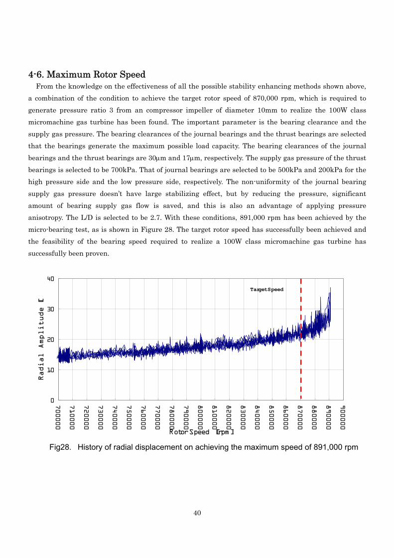
4-6. Maximum Rotor Speed From the knowledge on the effectiveness of all the possible stability enhancing methods shown above,
a combination of the condition to achieve the target rotor speed of 870,000 rpm, which is required to generate pressure ratio 3 from an compressor impeller of diameter 10mm to realize the 100W class micromachine gas turbine has been found. The important parameter is the bearing clearance and the supply gas pressure. The bearing clearances of the journal bearings and the thrust bearings are selected that the bearings generate the maximum possible load capacity. The bearing clearances of the journal bearings and the thrust bearings are 30μm and 17μm, respectively. The supply gas pressure of the thrust bearings is selected to be 700kPa. That of journal bearings are selected to be 500kPa and 200kPa for the high pressure side and the low pressure side, respectively. The non-uniformity of the journal bearing supply gas pressure doesn’t have large stabilizing effect, but by reducing the pressure, significant amount of bearing supply gas flow is saved, and this is also an advantage of applying pressure anisotropy. The L/D is selected to be 2.7. With these conditions, 891,000 rpm has been achieved by the micro-bearing test, as is shown in Figure 28. The target rotor speed has successfully been achieved and the feasibility of the bearing speed required to realize a 100W class micromachine gas turbine has successfully been proven.
0
10
20
30
40
700000
710000
720000
730000
740000
750000
760000
770000
780000
790000
800000
810000
820000
830000
840000
850000
860000
870000
880000
890000
900000
Rotor Speed [rpm]
Radial Amplitude [
Target Speed
Fig28. History of radial displacement on achieving the maximum speed of 891,000 rpm

41
The rotor vibration signals of radial and axial direction in time domain are shown in Figure 29. The figure shows two dominant frequencies in radial displacement data. The high frequency component is 1/rev signal and the low frequency component is whirl oscillation. The frequency of the 1/rev signal is 8 times that of the whirl oscillation. This suggests that the whirl frequency of approximately 11,000rpm is still lower than the first critical speed, which is predicted to be less than 10,000rpm in Figure 10. The effect of the thrust bearing supply gas on the conical mode natural frequency is not included in the rotordynamic analysis performed to make Figure 1. From Figure 27, the first resonance point is expected to be around 900,000rpm, hence the actual first resonance frequency is expected to be around 11,2500rpm.
Fig29. Time domain shaft vibration signal at 870,000 rpm

42
4-7. Power Requirements Since the condition of the hydroinertia gas bearings to stably run the rotor at 870,000 rpm has
experimentally found, the power required to drive the rotor can now be calculated. The power required to drive the rotor supported by hydroinertia gas bearings corresponds to the sum of viscous losses and the power to generate the pressurized feeding gas, while it corresponds only to the viscous losses for hydrodynamic gas bearings. Hence, the total power required to drive types of gas bearings in consideration.
The viscous loss of journal and thrust bearings at various bearing clearances are shown in Figure 30. Bearing clearance 5μm approximately corresponds to hydrodynamic gas bearings, such as herring-bone groove bearings and foil bearings. Bearing clearance 30μm for journal bearings and 15-20μm for thrust bearings corresponds to hydroinertia gas bearings. The breakdown of the required total power is shown in Table 3.
Table.3 Power required to drive the 4mm rotor to 870,000rpm
Bearing Type Viscous Loss [W]
Supply gas power [W]
Pressure Flow rate
13 0.2MPa-g 6SLM 2 Journals 2 121 108 0.6MPa-g 34SLM
2 Thrusts 16 164 0.7MPa-g 42SLM Subtotal 18 285
Hydroinertia
Total 303W
2 Journals 12 - 2 Thrusts 56 - Subtotal 68 -
Hydrodynamic
Total 68W
Although the viscous loss is far lower than that of hydrodynamic gas bearings, the power required to generate the pressurized bearing supply gas is very large because the required pressure found in the bearings tests is very high. Note that the supply gas power in Table 3 is the required power to generate the supply gas of specified pressure and flow rate by a compressor of 100% efficiency, and the actual power required to generate the pressurized supply gas is higher. Hence, hydroinertia gas bearings will require 5 times larger power to operate than hydrodynamic gas bearings. Therefore, it is better to use hydrodynamic gas bearings if they can provide stable operation at the design speed as high as 870,000rpm, and the study on hydrodynamic gas bearings should be continued to find the capability of stable operation at the design speed.

43
(a) Journal bearing
0
1
2
3
4
5
6
7
8
0 200000 400000 600000 800000 1000000
Rotor Speed [rpm ]
Viscous Loss [W] Bearing Gap ��‚Tƒ Ê‚ �
‚P‚Oƒ Ê‚ �
‚R‚Oƒ Ê‚ �
‚Q‚Oƒ Ê‚ �
0
1
2
3
4
5
6
7
8
0 200000 400000 600000 800000 1000000
Rotor Speed [rpm ]
Viscous Loss [W] Bearing Gap ��‚Tƒ Ê‚ �
‚P‚Oƒ Ê‚ �
‚R‚Oƒ Ê‚ �
‚Q‚Oƒ Ê‚ �
(Hydrodynamic gas bearings)
(Hydroinertia gas bearings)
0
5
10
15
20
25
30
35
40
0 200000 400000 600000 800000 1000000
Rotor Speed [rpm ]
Viscous Loss [W]
Bearing Gap ��‚Tƒ Ê‚ �
‚P‚Oƒ Ê‚ �
‚R‚Oƒ Ê‚ �
‚Q‚Oƒ Ê‚ �
0
5
10
15
20
25
30
35
40
0 200000 400000 600000 800000 1000000
Rotor Speed [rpm ]
Viscous Loss [W]
Bearing Gap ��‚Tƒ Ê‚ �
‚P‚Oƒ Ê‚ �
‚R‚Oƒ Ê‚ �
‚Q‚Oƒ Ê‚ �
(Hydroinertia gas bearings)
(Hydrodynamic gas bearings)
(b) Thrust bearing Fig.30 Viscous loss of the bearing at various clearances
44
5. Design of Hydrodynamic air bearings Although the target speed has successfully been achieved by hydroinertia air bearings, it has been found that the bearings require significantly high supply air pressure to sustain the stability at current high speed, and the power required to generate the high pressure supply air is very large. From the power requirement and also from the simplicity of the system without supply air system, hydrodynamic air bearings should also be studied.
To begin the study, first, Herringbone and spiral-groove type hydrodynamic air bearings are designed. These types are chosen because they have following advantages.
(1) A lot of information based on experience on their design and performance are available. (2) The required anti-whirl stability can theoretically be obtained. (3) The bearings can be fabricated by technology available in our research group.
The weaknesses of these types of bearings are as follows. (1) Load capacity is small at low speed (2) Requirs high accuracy fabrication of sub-micron level because the bearing clearance is an
order smaller than hydroinertia air bearings. (3) Compliancy of the bearing is extremely small due to rigid wall and small bearing clearance.
Hence in practical design, extra care should be taken for material selection that the difference of thermal expansion rates of the rotor and the bearing sleeves is small.
In following subsections, the hydrodynamic air bearings are designed within the bearing clearances those seem to be practically feasible values.

45
5-1. Design of self-acting Herringbone grooved journal bearings The self-acting Herringbone grooved hydrodynamic air bearing has been designed by a method compiled by Togo [13]. The method uses the empirical database tabulated in reference 13. For the first design practice, the shaft diameter D is selected to be 6mm to make the fabrication easier. To have the same circumferential speed, the rotor speed is set to 600,000rpm. The bearing length L is selected to be 6mm, the same as the shaft diameter D. The weight of the designed rotor is 6.74g by separate structural design. Hence the weight that each of the 2 journal bearings have to support is 3.37g. Now, using following relations with tabulated data, 3 major parameters are calculated as follows, after some iterations. Bearing Number
7.1062
=⎟⎟⎠
⎞⎜⎜⎝
⎛=Λ
ra CR
Pμω
(eq.1)
Load Capacity
37.32 === mWDLPW aε (eq.2)
Dimensionless Mass Parameter
61.82
5
2 =⎟⎠⎞
⎜⎝⎛=
RC
LmP
M ras μ
(eq.3)
where, =R journal radius = 3 [mm] =rC bearing clearance = 7.5 [μm]
=ω rotational speed = 20,000π [rad/sec] =m rotor mass = 6.74 [g]
=μ viscosity coefficient of the air=1.833x10⁻¹⁰[kgf-s/cm2] =aP ambient pressure=1.033[kgf/cm2] =ε eccentricity ratio=displacement of the rotor/Cr = 0.4
=W non-dimensional load capacity (from the table in ref[13]) = 0.654 The other parameters are found as follows from the table 4.4 in ref[13].
Clearance ratio 54.2==Γr
g
CC
where, =gC bearing clearance at the groove = 11.5 [μm].
Groove width ratio rg
g
aaa+
=α =0.6
where, =ga groove width=1.028 [mm], =ra ridge width,

46
grg N
Raa π2=+ , and =gN number of grooves = selected to be 11.
Groove length ratio LL
Z g= =1 where, =gL groove length.
Groove angle =β 34.1 [deg].
The definition of various geometric parameters are shown in Figure 31.
Fig.31 Definition of various bearing geometric parameters of self-acting Herringbone grooved journal bearing

47
5-2. Design of self-acting Spiral grooved thrust bearings The type of thrust bearing is selected to be a pump-in type self-acting spiral grooved bearing to locate the thrust disk at the outside of the shaft. The definitions of the geometric parameters are shown in Figure 32. The inner diameter 2Ri is set to be 6.3mm to set the bearing outside the 6mm shaft, and the outer diameter 2Ro is set to be twice the inner diameter, 12.6mm. The load capacity of the thrust bearing is required to be larger than 400gf at 600,000rpm of the rotor speed. Then the required bearing clearance h is calculated from the following equations and the data table 4.1 in ref[13] as follows.
Bearing Number 6.2332
22
=⎟⎟⎠
⎞⎜⎜⎝
⎛ −=Λ
hRR
Pio
a
μω,
Load Capacity WRRPW ioa )( 22 −= π =415.4 [gf]
where, =h bearing clearance = 6.5 [μm]
=W 0.68 from the data table 4.1 in ref [13] =ω rotational speed = 20,000π [rad/sec]
=μ viscosity coefficient of the air=1.833x10⁻¹⁰[kgf-s/cm2] =aP ambient pressure=1.033[kgf/cm2]
and the other parameters are found from the table 4.1 in ref [13] as follows.
hhhg 3=− = groove depth = 19.5 [μm]
=1b land width = 1.9 [mm] =2b groove width = 1.2 [mm]
=−
−
i
g
RRRR
0
0 groove end radius ratio = 0.7.
Now, since the calculated load capacity is that of one thrust bearing, and thrust bearings will be used in a pair to keep the axial position of the rotor, actual load capacity to work on the rotor is the difference of the load capacities of the two thrust bearings. Hence the bearing clearance to make the load capacity of the other side of the thrust bearing lower than 415.4 g (calculated value) – 400 g (requirement) = 15.4g, will be calculated by a similar way. The calculation tells that the load capacity reduces to W=9.7g at h=33.5μm. Hence the total clearance of the thrust bearing, which is the addition of these two numbers, is 40 μm.

48
Fig.32 Definition of various bearing geometric parameters of pump-in type self-acting spiral grooved thrust bearing

49
6. Summary 1. A micro-bearing tester has been developed, and successfully used to test the hydroinertia gas
bearings of journal diameter 4mm and the thrust disk outer diameter 10mm. 2. The effect of the bearing supply gas pressure and the bearing clearances are found to be have large
effect on increasing the maximum achievable rotor speed. 3. The pressure anisotropy and the L/D of the journal bearings are shown to have stabilizing effect for
the whirl instability, but the effect has been found to be significantly small compared to the incompressible analysis results. The reason of these effects being small is analyzed by the numerical simulation of the flow inside the bearing. The pressure anisotropy is found to be reduced rapidly when the L/D of the bearing is not very small.
4. By selecting appropriate bearing clearances, supply gas pressure and its non-uniformity, and L/D, maximum rotor speed of 891,000 rpm has been achieved. This is certainly the world record for a configuration with 10mm 3-dimensional (non-MEMS) turbine at the end of the shaft. The feasibility of the bearing for a practical rotor configuration to realize a 100W class micromachine gas turbine has successfully been proven.
5. Hydroinertia air bearings require relatively large amount of high pressure supply air. Hence the total power required to operate the rotor-bearing system including that to compress the air, is found to be larger for hydroinertia air bearings than for hydrodynamic air bearings.
6. A set of self-acting Herringbone and Spiral grooved hydrodynamic air bearings is designed for 6mm shaft. The designed bearing clearances are 7.5μm for the journal bearing and 40μm(total clearance) for the thrust bearing, which seem to be practically feasible values.

50
7. Remaining works (1) The self-acting Herringbone and Spiral grooved hydrodynamic air bearings will be fabricated and be
tested. (2) Hydrodynamic air bearings with larger compliancy should be studied. Studies on foil bearings will be
conducted. (3) Rotordynamics of the shaft to integrate the bearing systems in gas turbine/ jet engine system should
be studied. (4) The effect of the heat on the bearing performance should be studied.

51
REFERENCES [1] Epstein, A. H., “Millimeter-Scale, Micro-Electro-Mechanical Systems Gas Turbine Engines”, ASME J.
of Eng. for GT and Power, Volume 126, pp. 205-226, 2004. [2] Isomura, K. et al., "Feasibility Study of a Gas Turbine at Micro Scale", ASME paper 2001-GT-101,
2001. [3] Salehi M. et al., “Operation of a Mesoscopic Gas Turbine Simulator at Speeds in Excess of 700,000 rpm on Foil
Bearings”, ASME paper GT2004-53870, 2004. [4] Togo, S., “Comparative Study on the Performance of High-Speed Air Bearing at Micro-Scale: Final
report” AOARD/AFOSR Contract number : F62562-03-P-0583, February 2005 [5] Isomura, K. et al., “Analytical and Experimental Study of Hydroinertia Gas Bearings for
Micromachine Gas Turbines", ASME paper GT2005-68401, 2005. [6] Spakovszky, Z. and Liu, L. X., “Scaling Laws for Ultra-Short Hydrostatic Gas Journal Bearings,”
ASME DETC2003/VIB-48468, September 2003. [7] Liu, L. X. and Spakovszky, Z., “Effects of Bearing Stiffness Anisotropy on Hydrostatic Micro Gas
Journal Bearing Dynamic Behavior”, ASME GT2005-68199, June 2005. [8] E. Shima and T. Jounouchi, “Role of CFD in aeronautical engineering (No. 14) - AUSM type upwind
schemes - ”, Proceedings of the 14th NAL Symposium on Aircraft Computational Aerodynamics, pp. 7-12, 1997.
[9] M. S. Liou and C. J. Steffen Jr, “A new flux splitting scheme”, Journal of Computational Physics, vol. 107, pp. 23-39, 1993.
[10] Watanabe, N. et al., “Aerodynamic Design Factors for Ultra-Micro Radial Inflow Turbine”, ISABE2005-1274, September 2005.
[11] S. Obayashi, K. Matsushima, K. Fujii and K. Kuwahara, “Improvements in Efficiency and Reliability for Navier-Stokes Computations Using the LU-ADI Factorization Algorithm”, AIAA 86-0338, 1986.
[12] Spalart, P. R. and Allmaras, S. R., “A One-Equation Turbulence Model for Aerodynamic Flows”, AIAA paper 92-0349, 1992.
[13] Togo, S.,“Gas Bearing Design Handbook”, Kyoritsu Publishing Co., Ltd. January 2002, in Japanese