COMPARATIVE ANALYSIS BETWEEN A PARABOLIC TROUGH...
18
Advances and Applications in Mechanical Engineering and Technology Volume 2, Number 1/2, 2010, Pages 1-18 Keywords and phrases: parabolic trough collector, compact linear Fresnel reflector, absorption system, GAX cycle. Received May 25, 2010 2010 Scientific Advances Publishers COMPARATIVE ANALYSIS BETWEEN A PARABOLIC TROUGH COLLECTOR AND A COMPACT LINEAR FRESNEL REFLECTOR TO BE USED AS DIRECT GENERATOR OF AN ADVANCED ABSORPTION COOLING SYSTEM D. SAUCEDA, N. VELÁZQUEZ, R. BELTRÁN and A. LUNA Centro de Estudios de las Energías Renovables Universidad Autónoma de Baja California Calle de la Normal s/n Colonia Insurgentes Este Mexicali, B. C. 21280 México e-mail: [email protected] Abstract A comparative analysis between a parabolic trough collector (PTC) and a compact linear Fresnel reflector (CLFR) is presented. A mathematical model for each concentrator is developed, a computational algorithm in order to solve the rigorous mathematical model is proposed, and a numerical simulation exploring the critical variables that define the operational performance of both concentrators is done. According to the obtained results, it can be concluded that the parabolic trough solar collector has important advantages that makes it the best option to be used as a direct generator of an advanced solar-GAX cooling system. Its thermal efficiency is about 10.5% higher than that of the Fresnel concentrator, therefore, the energy demand of the cooling cycle could be satisfied with a smaller equipment, if this concentrator is used.
Transcript of COMPARATIVE ANALYSIS BETWEEN A PARABOLIC TROUGH...

Advances and Applications in Mechanical Engineering and Technology Volume 2, Number 1/2, 2010, Pages 1-18
Keywords and phrases: parabolic trough collector, compact linear Fresnel reflector, absorption system, GAX cycle.
Received May 25, 2010
2010 Scientific Advances Publishers
COMPARATIVE ANALYSIS BETWEEN A PARABOLIC TROUGH COLLECTOR AND A COMPACT LINEAR FRESNEL REFLECTOR TO BE USED AS DIRECT GENERATOR OF AN ADVANCED ABSORPTION
COOLING SYSTEM
D. SAUCEDA, N. VELÁZQUEZ, R. BELTRÁN and A. LUNA
Centro de Estudios de las Energías Renovables Universidad Autónoma de Baja California Calle de la Normal s/n Colonia Insurgentes Este Mexicali, B. C. 21280 México e-mail: [email protected]
Abstract
A comparative analysis between a parabolic trough collector (PTC) and a compact linear Fresnel reflector (CLFR) is presented. A mathematical model for each concentrator is developed, a computational algorithm in order to solve the rigorous mathematical model is proposed, and a numerical simulation exploring the critical variables that define the operational performance of both concentrators is done. According to the obtained results, it can be concluded that the parabolic trough solar collector has important advantages that makes it the best option to be used as a direct generator of an advanced solar-GAX cooling system. Its thermal efficiency is about 10.5% higher than that of the Fresnel concentrator, therefore, the energy demand of the cooling cycle could be satisfied with a smaller equipment, if this concentrator is used.
D. SAUCEDA et al. 2
1. Introduction
In recent years, an increasing interest in research and development of sustainable cooling technologies able to compete or even replace conventional vapour compression systems have been observed, because of the drawbacks of the latter (very high power required for their operation and serious environmental problems associated with the refrigerants used in this technology).
Absorption cooling systems thermally activated by solar collectors are considered as a very promising alternative since their main energy source is obtained from renewable resources, and at the same time, they use natural refrigerants that do not contribute to the global warming and do not damage the ozone layer. Two technologies converge in these systems: Absorption cooling technology and solar concentrating technology. Throughout the years, absorption cooling systems have evolved, and at the moment, the cycles with internal heat exchange between the absorber and the generator (GAX) are the most attractive due to their higher levels of efficiency and lower number of components compared to other advanced cycles. Regarding the concentrating solar technology, originally, PTC and CLFR were designed to heat a fluid, but now they are used to generate vapour directly in their receptors [18]. This technology is known as direct steam generation (DSG) and is mainly used in electric power generation [5]. Kalogirou et al. [9] proposed a direct steam generation system by using flash evaporation, where steam is generated after warming up water at high pressure, and later the pressure is reduced in an expansion tank. By doing this, only one phase is present in the receiver of the PTC, therefore, the problem related to the thermal stress caused by the temperature gradient, when two phases are present is avoided. Flores and Almanza [6] studied a PTC with a bimetallic receiver for direct steam generation, looking to solve the problem of deformation caused by the non-uniform heating appearing due to the existence of a stratified flow in two phases in the receiver. The Fresnel solar concentrator was invented by Francia [7] and in the last years, several

COMPARATIVE ANALYSIS BETWEEN A PARABOLIC … 3
studies have been conducted in order to evaluate its technical and economic feasibility to be used in systems of direct steam generation for electricity production [11, 12]. Velázquez et al. [17] proposed a CLFR to generate steam directly in its receiver and to activate an advanced absorption cooling system. They reported that a Fresnel concentrator is a good option to be used as direct generator of an advanced absorption cooling system in view of the fact that, the process can be done at high temperatures beneficial to the cooling cycle. In addition, the efficiency of the concentrator is not affected in any significant way.
Based on the advantages that represent the direct steam generation in solar concentrators and the attractiveness of an advanced absorption cooling system activated directly by a solar concentrator, in this work, a mathematical model of a PTC and a CLFR is developed. A numerical simulation for each one of them exploring the most important variables that define its operational behavior and a comparative analysis to determine the best option to be used as direct generator of an advanced absorption cooling system is carried out.
2. Physical Description
Figure 1(a) shows a schematic diagram of a PTC. It consists of a reflective surface with a parabolic shape that reflects all the normally incident energy over its aperture area towards a receptor tube placed on the focus line. The receptor tube is surrounded by a glass cover with air in the annulus in order to reduce the convection loses between the receptor and the surroundings. Figure 1(b) shows the CLFR scheme. It is composed of flat mirrors set placed at the correct distance of the center to avoid shading between them, and at specific angle to reflect the beam incident normally over its aperture area towards a common focus, where a receptor tube surrounded by a glass cover with air in annulus is placed.

D. SAUCEDA et al. 4
Figure 1. Schematic diagram of the systems evaluated.
3. Operative Description
The solar concentrators studied are used as direct generators of an advanced solar cooling system; they receive a saturated ammonia water mixture at ,C186° 18 bar, 6.73% ammonia, and 0.0197kg/s. When the mixture receives latent heat along the receptor tube, a phase change takes place and at the end of the receptor, the mixture is in two phases for its posterior separation and reintegration to the cooling cycle.
4. Methodology
Figure 3 shows the algorithm developed for the resolution of the mathematical model and the study of the different parameters that define the operational performance of the solar concentrators. Using this tool, each one of the concentrators was dimensioned in order to satisfy the thermal requirements of an advanced absorption cooling system of 10.5kW capacity. The following assumptions have been made in the simulation study.
● Both concentrators are 3m width.
● Both concentrators have a perfect solar tracking system in two axes.
● The aperture plane of both concentrators is normal to the incident solar beam radiation.

COMPARATIVE ANALYSIS BETWEEN A PARABOLIC … 5
● Width of receptor tube diameter of the CLFR is equal to the mirrors width.
Figure 2. Computational algorithm used in the design of the systems.

D. SAUCEDA et al. 6
4.1. Optical and geometrical analysis
Position and angle of the first mirror in the CLFR are calculated by the following equations [10]:
,tan21 ξ+= fWd (1)
.sin2
cos2tan21
1
1111
θ−
θ+=θ −
Wf
Wd (2)
Position and angle of the second to ”“n mirrors are calculated by an iterative method by using the following equations:
( ),2tansin 1 ξ+θθ= − nnn WG (3)
,cos 11 nnnn GWdd +θ+= −− (4)
.sin2
cos2tan21 1
θ−
θ+=θ −
n
nnn Wf
Wd (5)
For a PTC, the minimal diameter required in the receptor tube in order to receive all the reflected rays from the reflective surface, is calculated by [4]:
,sin267.0sin
φ= cWD (6)
where the aperture angle is defined by:
,116
8tan 2
1
−
=φ −
c
c
WfWf
(7)
geometrical concentrating ratio is calculated by:
PTC:
.,
,
extr
extrcD
DWC
π−
= (8)
COMPARATIVE ANALYSIS BETWEEN A PARABOLIC … 7
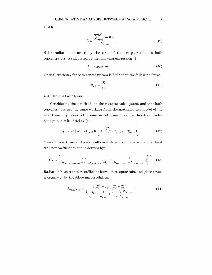
CLFR:
.cos
,1
extr
NN
iDCπ
θ=∑ = (9)
Solar radiation absorbed by the area of the receptor tube in both concentrators, is calculated by the following expression [1]:
.aob KIS ταγρ= (10)
Optical efficiency for both concentrators is defined in the following form:
.b
op IS=η (11)
4.2. Thermal analysis
Considering the similitude in the receptor tube system and that both concentrators use the same working fluid, the mathematical model of the heat transfer process is the same in both concentrators, therefore, useful heat gain is calculated by [4]:
( ) ( ) .,,
−−−= ambentf
Lextru TTC
USLDWFrQ (12)
Overall heat transfer losses coefficient depends on the individual heat transfer coefficients and is defined by:
( ) ( ) .11
,,clocie,,
−
−−−−
+
++
=crconvcrradcradambcconv
rL hhAhh
AU (13)
Radiation heat transfer coefficient between receptor tube and glass cover, is estimated by the following correlation:
( ) ( )( ) .111
,
,
22,
intcc
extrc
crrr
crcrcrrad
DD
F
TTTTh
εε−
++εε−
++σ=
−
− (14)

D. SAUCEDA et al. 8
Convection heat transfer coefficient between receptor tube and glass cover, is calculated by:
( ) ,ln2
,,,,
extrintcextr
effcrconv DDD
kh =− (15)
where effk is obtained from [15] correlation:
( ) ,317.0 41∗= Rakkeff (16)
∗Ra is the modified Rayleigh number and is calculated by:
( )( )
,11
ln 4145
53,
53,
43
,,41 Ra
DDb
DDRa
intcextr
extrintc
+
=∗ (17)
.2,, extrintc DD
b−
=
Radiation heat transfer coefficient between glass cover and surroundings, is calculated by [14]:
( ) ( ).22, cskycskycskycrad TTTTh ++σε=− (18)
Convection heat transfer coefficient between glass cover and surroundings, is estimated by the correlation [8].
,,
,extc
airnambcconv D
kReCh =− (19)
where C and n are constants defined as follows:
for ,466.0,615.0400040 ==≤< nCRe
for ,618.0,174.0400004000 ==≤< nCRe
for .805.0,0239.040000040000 ==≤< nCRe

COMPARATIVE ANALYSIS BETWEEN A PARABOLIC … 9
Convection heat transfer coefficient from internal wall of the receptor tube toward two phase ammonia water mixture, is calculated by using Mishra et al. [13] correlation as follows:
,165 mn
ttltp Boxhh
= (20)
where 5.0=n and [ ] ttxm ,1615.0= is the Lockhart-Martinelly
parameter defined by:
,1 1.05.09.0
µµ
ρρ
−=
gl
l
g
g
gtt X
Xx (21)
lh is the convection heat transfer coefficient for the liquid phase, and it is
calculated by the [3] correlation:
,023.0,
4.08.0intr
l DKPrReh = (22)
Bo is the boiling number defined as follows:
.λ
= GqBo (23)
Global efficiency for both collectors is calculated by:
.bref
uth IA
Q=η (24)
Fluid temperature at the end of the receptor tube, is calculated by using an iterative method guessing temperature values until the next balance is reached:
( ),HmQu ∆= (25)
H∆ is the difference between the inlet and outlet enthalpy.
Transport properties are evaluated by using Conde correlations [2]; thermodynamics properties are estimated by Ziegler and Trepp correlations [19].

D. SAUCEDA et al. 10
5. Results and Discussion
A numerical simulation study in order to size, predict the operational performance and to select the best option to be used as direct generator of an advanced absorption solar cooling system between a PTC and a CLFR has been carried out. Materials utilized and dimensions obtained were selected in order to obtain maximum optical and thermal efficiency considering the following conditions:
● Thermal energy demanded by an advanced absorption cooling cycle (12.23kW).
● 3m width for both concentrators.
● Meteorological conditions of Mexicali B. C. Mexico.
● Receptor tube diameter and glass cover diameter commercially available.
Table 1 shows the most important design variables and dimensions for each one of the concentrators. In the study of the solar concentrating technology, one of the most important aspects is the optical and geometrical study. Figure 3 demonstrates how some of the geometrical parameters such as focus distance, receptor tube diameter, and geometrical concentrating ratio were chosen for both concentrators. For the PTC (3a), the maximum concentration ratio is 32.9 with a focus distance of 0.75m, while for the CLFR (3b), the concentration ratio is 14.2 with a focus distance of 2m. The difference in the concentration ratio is due to the fact that PTC takes advantage of all the aperture area, while in the CLFR, the mirrors are separated and as a consequence, the effective area is lesser than in the PTC. By means of similar parametric studies, the number of mirrors in the CLFR, the receptor tube diameter, the glass cover diameter, and the rest of dimensions were specified as shown in Table 1.

COMPARATIVE ANALYSIS BETWEEN A PARABOLIC … 11
Table 1. Design and working conditions of the systems studied
Parameter CLFR PTC
Mass flow rate 0.0197kg/s
Inlet temperature 184.98°C
Inlet pressure 18 bar
Inlet ammonia concentration 7.18%
Ambient temperature 39°C
Receptor internal diameter 0.05250m 0.0199m
Receptor external diameter 0.06032m 0.0267m
Cover internal diameter 0.08m 0.045m
Cover external diameter 0.085m 0.05m
Width 3m
Length 8.71m 7.18m
Receptor absorbance 0.9 (dimensionless)
Shape factor due to inexact concentrator orientation 1.0 1.0
Number of mirrors 46 -
Focal distance 2m 0.75m
Mirror reflectivity 0.92 (dimensionless)
Receptor emittance 0.35 (dimensionless)
Cover emittance 0.88 (dimensionless)
Receptor conductivity (carbon steel) 55W/m K
Air velocity 2.3m/s
Geometrical concentration ratio 14.22 32.91
Solar beam radiation 900W/m2

D. SAUCEDA et al. 12
Figure 3. Geometrical parameters selection for the solar collectors.
Figure 4 illustrates how the useful heat demanded by the cooling system is satisfied in different length for each concentrator. In the case of the PTC, 7.18m are needed, while the CLFR requires 8.71m. This is due mainly to the difference in the receptor tube diameter in each concentrator, the PTC has a receptor diameter of 0.0267m, which is about half than that of the CLFR. When the diameter is bigger, the heat transfer area increases causing higher thermal losses to the surroundings. This effect is also observed in the individual heat transfer coefficients, which depend of the transversal area and heat transfer area. The higher geometrical concentration ratio in the PTC is also reflected in the higher useful heat gain compared with the CLFR. As shown in Figure 4, the outlet quality of the mixture is higher too in the PTC, because if more heat is transferred, more ammonia vapour is released.

COMPARATIVE ANALYSIS BETWEEN A PARABOLIC … 13
Figure 4. Energy gain and output quality against receptor length comparison.
Figure 5 shows useful heat transfer and thermal efficiency against different levels of solar beam radiation for both concentrators, as shown. There is a difference between the efficiency of the concentrators, that of the PTC being 10.5% higher than that of CLFR. As mentioned above, this is due to the difference of heat transfer area, in the individual heat transfer coefficients and in the geometrical concentration ratio in both concentrators.
The performance of the solar-GAX cycle directly activated by the solar concentrators and the efficiency of both concentrators varying the generator temperature are shown in Figure 6. It can be seen that unlike conventional solar thermal cooling systems activated by flat collectors, in this configuration, with generator temperature increase, the efficiency of the cooling cycle is incremented without affecting in a significant way the collector efficiency.

D. SAUCEDA et al. 14
Figure 5. Energy gain and efficiency against solar beam radiation comparison.
Generator temperature ( C° )
Figure 6. Solar-GAX and collector efficiencies against generator temperature.

COMPARATIVE ANALYSIS BETWEEN A PARABOLIC … 15
6. Conclusion
A comparative analysis between a PTC and a CLFR in order to determine which one of these would be the best choice to be used as direct generator of an advanced absorption cooling cycle has been carried out. According to the obtained results, it can be concluded that both concentrators can provide the quantity and quality of thermal energy demanded by the cooling cycle, although, the PTC has several advantages that makes it the best option. Its thermal efficiency and geometric concentration ratio are 10.5% and 131%, respectively, higher than that of the CLFR, therefore, a smaller system is required to satisfy the energy
demanded by the cooling cycle ( ** m0.3CLFR;m18.7m0.3PTC ==
).m71.8 On the other hand, by using a solar concentrating collector as a
direct generator in an advanced cooling cycle, allows working at higher temperature favouring the COP of the cooling cycle without affecting in any significant way the efficiency of the collector.
Acknowledgement
Authors wish to thank CONACYT and Baja California Government for their financial support through the project FOMIX-76927.
Nomenclature
cA Internal heat transfer cover area [ ].m2
rA External heat transfer receptor area [ ].m2
Bo Boiling number [dimensionless].
Cp Specific heat at constant pressure [ ].KJkg 11 −−
C Geometrical concentration ratio [dimensionless].
D Diameter [m].
F Focal distance [m].

D. SAUCEDA et al. 16
G Flow mass velocity [ ].smkg 12 −−
H Enthalpy [ ].Jkg 1−
h Heat transfer coefficient [ ].Km W 12 −−
bI Solar beam radiation [ ].m W 2−
K Thermal conductivity [ ].KmW 11 −−
aK Incident angle modifier [dimensionless].
L Length [m].
m Mass flow rate [ ].skg 1−
Pr Prandtl number [dimensionless].
Q Heat flow per unit area [ ].mW 2−
uQ Energy gain [W].
Ra Rayleigh number [dimensionless].
Re Reynolds number [dimensionless].
S Solar absorbed energy per unit area [dimensionless].
T Temperature [ ].C°
LU Overall heat transfer losses [ ].KmW 12 −−
W Mirror width [m].
cW PTC width [m].
Subscript
r Receptor
amb ambient

COMPARATIVE ANALYSIS BETWEEN A PARABOLIC … 17
c Cover
conv convective
ent Inlet
ext external
f Fluid
int internal
l Liquid
op Optical
rad radiative
tp Two phases
g Vapour
References
[1] R. Almanza and F. Muñoz, Ingeniería de la Energía Solar, El Colegio Nacional, D. F. Mexico, 1994.
[2] M. Conde, Thermophysical properties of (NH3 + H2O) solutions for the industrial design of absorption refrigeration equipment (2006),
www.mrc-eng.com/aquaammonia.htm
[3] F. W. Dittus and L. M. K. Boelter, Heat transfer in automobile radiators of the tubular type, University of California Publications in Engineering 2 (1930), 443-461.
[4] J. A. Duffie and W. A. Beckman, Solar Engineering of Thermal Process, Second ed., Wiley-Interscience, New York, 1991.
[5] M. Eck and E. Zarza, Saturated steam process with direct steam generating parabolic troughs, Solar Energy 80(11) (2006), 1424-1433.
[6] V. Flores and R. Almanza, Direct steam generation in parabolic trough concentrators with bimetallic receivers, Energy 29(5-6) (2004), 645-651.
[7] G. Francia, Pilot plants of solar steam generation systems, Solar Energy 12 (1968), 51-64.
[8] R. Hilpert, Warmeabgabe von geheizen Drahten und Rohren, 4(220) (1933).
[9] S. Kalogirou, S. Lloyd and J. Ward, Modelling, optimisation and performance evaluation of a parabolic trough solar collector steam generation system, Solar Energy 60(1) (1997), 49-59.

D. SAUCEDA et al. 18
[10] S. S. Mathur, T. C. Kandpal and B. S. Negi, Optical design and concentration characteristics of linear Fresnel reflector solar concentrators-II, Mirror elements of equal width, Energy Conversion and Management 31(3) (1991), 221-232.
[11] D. R. Mills and G. L. Morrison, Compact linear Fresnel reflector solar thermal powerplants, Solar Energy 68(3) (2000), 263-283.
[12] D. R. Mills, Advances in Solar Thermal Electricity Technology 76 (2004), 19-31.
[13] M. P. Mishra, H. K. Varma and C. P. Sharma, Heat Transfer Coefficients in Forced Convection Evaporation of Refrigerant Mixtures 8(2) (1981), 127-136.
[14] S. D. Odeh, G. L. Morrison and M. Behnia, Modelling of parabolic trough direct steam generation solar collectors, Solar Energy 62(6) (1998), 395-406.
[15] G. D. Raithby and K. G. T. Hollands, A general method of obtaining approximate solutions to laminar and turbulent free convective problems, Advances in Heat Transfer 11(265) (1975).
[16] W. Rivera and R. Best, Boiling heat transfer coefficients inside a vertical smooth tube for water/ammonia and ammonia lithium nitrate mixtures, International Journal of Heat and Mass Transfer 42(5) (1999), 905-921.
[17] N. Velázquez, O. García-Valladares, D. Sauceda and R. Beltrán, Numerical simulation of a linear Fresnel reflector concentrator used as direct generator in a solar-GAX cycle, Energy Conversion and Management 51(3) (2010), 434-445.
[18] E. Zarza et al., Direct steam generation in parabolic troughs: Final results and conclusions of the DISS project, Energy 29(5-6) (2004), 635-644.
[19] B. Ziegler and C. Trepp, Equation of state for ammonia-water mixtures, International Journal of Refrigeration 7(7) (1984), 101-106.
g