
Company Introduction - BongShin Trading HomePage · 2013-12-27 · Preservation Level Flow Pressure...
47
Transcript of Company Introduction - BongShin Trading HomePage · 2013-12-27 · Preservation Level Flow Pressure...


Company Introduction
To whom it may concern.
Thanks a lot for your love and help.Our company is a specialty production enterprise for parts of a transformer but we are not satisfied with technology and quality level of the present time,We will make every efforts to do responsibility to a society with business mind of a technology intensive period.and we will supply with a product of good quality, moderate prices and quick delivery for you're the heightening of international competitiveness,we will repay your obligations with continuous quality improvement and new products ect.ahead from now, we ask for your unchangeable cheer and assistance and we pray for the prosperity of your firm.
관계자 제위(諸位).
태진공업주식회사는 지금까지 아껴주시고 후원하여주신 여러분에게 깊은 감사를 드립니다.
저회 회사는 변압기 부품 전문생산 업체로서 현재의 기술 및 품질수준에 만족하지 않고 우
리는 기술 집약시대의 기업정신으로 사회에 대한책임을 다하기 위해여 노력할 것입니다.
또한 우리는 좋은 품질, 저렴한 가격 그리고 빠른 납기의 제품을 여러분의 국제 경쟁력 제
고를 위하여 공급하겠으며, 끊임없는 품질개선과 신제품 개발 등으로 모든 분들의 은혜에
보답 할 것입니다.
앞으로 변함없는 성원과 도움을 부탁드리며 여러분의 사업이 날로 번창하시 길 기원 합니다.
Quality PolicyWe do our best to realize customer's admiration based on reliance of the quality.
품질방침
우리는 품질의 신뢰성을 근본으로 하여 고객감동이 실현될 수 있도록 최선을 다한다.
The Right Choice, For Your Power Equipments!

History of Company
199906 : Established. 10 : Certified ISO-9001 Quality System.
200311 : Developed 12P BCT Terminal Box for Power Transformer.
200407 : Developed SF6 Gas Cooler for SF6 Power Transformer.
200505 : Developed Axial Cooling Fan for Power Transformer.08 : Developed Gas Accumulation Ind. for Power Transformer.
200604 : Developed 50Ø PRD, Oil Flow S/W, 3inch v/v for KTX Train08 : Developed Low Noise Cooling Fan for Power Transformer.
200710 : Developed Gas Detector Relay for Power Transformer.
201006 : Obtained CE Certification for 6 items of Cooling Fan12 : Developed 175Ø PRD Housing for Power Transformer.

PreservationDehydrating Breather
LevelOil Level Gauges . Indicators
FlowOil Flow Indicator
PressurePressure Relief Device
ProtectBuchholz Relay
PreservationN2 Gas Equipments
ValveValves
TemperatureTemperature Indicator
CoolingCooling Fan
TerminalBCT Terminal Box
The Right Choice, For Your Power Equipments!

Dehydrating Breather
Product Group : T01
The dehydrating breather is connected to conservator or Gas Oil Sealing Tank as one of oil conservation systems through long pipe.The dehydrating breather is an apparatus to reduce effectively the thermal ageing of insulation oil by means of filtering off the particles of atmosphere in oil cup and absorbing the moisture of atmosphere in silica gel container when a transformer is under breathing in accordance with the variation of oil level caused by the change of ambient temperature and/or transformer load.The dehydrating breather is located at a suitable height to check the breather at the standing point of operator and has a very simple construction for disconnecting it from the pipe line of transformer conservator during the transportation period of transformer and reconnecting it to the pipe line at transformer erection site after delivery. We have various dehydrating breathers in size as well as in shape for all the transformers from pole transformers to ultra high voltage class power transformers because the dehydrating breather should be chosen in accordance with the kind and capacity of transformer.The breathers have a good reputation in the world market because the breathers have a solid construction and a graceful shape as well. We use No Cobalt Silicagel of pro-environment as dehydrator to be filled in the container of all breathers.Since the European Union had completely revised their regulations of EU Directive 98/98/EC on July 01, 2000 and also the regulations have been applied to all the products, Cobalt chloride prescribed as a potential carcinogenic material have been prohibited from using and all products manufactured by means of using it have been prohibited from selling, actually.On the other hand, the No Cobalt Silicagel is made from another material of pro-environment definitely different from toxic material prescribed by their regulations of EC Legislation, . dehydrating breather can be used by transformer owners without any anxiety.
호흡기는 유입식 변압기의 절연유 보존장치인 콘서베이타 혹은 가스오일씨일탱크(GOST)와 연결되는 긴 파이프에 부착되어 온도변화
에 따른 유면 변동에 의한 호흡작용 시 공기 중에 포함된 먼지와 습기를 제거함으로써 절연유 열화정도를 효과적으로 줄이는 작용을
하는 장치입니다.
호흡기는 보통 육안으로 관찰하기 좋은 위치에 설치되어 있으며, 본체와 분리되어 운반된 후 현장에서 조립되므로 취급이나 설치·
보수가 간편해야합니다.
태진공업(주)의 호흡기는 장착되는 변압기의 종류와 특성에 따라 그 크기와 모양이 다양하여 주상변압기로부터 초초고압(UHV)의 전력
용 변압기 등에도 사용할 수 있도록 다양한 제품군을 보유하고 있으므로 폭넓은 선택의 범위를 제공하고 있을 뿐 아니라 견고한 구조와
미려한 외관으로 국내•외에서 그 제품의 우수성을 인정받고 있습니다.
태진공업(주)의 호흡기는 환경 친화적인 No Cobalt 실리카겔을 사용합니다. 유럽 연합국내에서는 2000년 7월 1일부터 새로운 EU
Directive 98/98/EC규정이 개정, 적용됨에 따라 잠재적 발암물질로 규정된 염화코발트 및 이를 이용한 제품의 제조, 유통이 사실상
금지 되었습니다. 본 실리카겔은 EC Legislation규정에 정의된 독성물질이 전혀 아닌 환경 친화적 원료를 사용하여 제조되기 때문에
안심하고 사용할 수 있습니다.
Product Table
Model Transformer Material / CapacityT0101T0162T0163T0165T0112(5K15A)T0130(5K25A)T0113G01(T0113)T0113G02(T0114)T0113G03(T0115)T0118G01(Tri-angle Flange)T0118G02(Tri-angle Flange)T0118G03(Tri-angle Flange)T0118G04(Tri-angle Flange)T0120T0121T0122T0167 K, E01T0167 K, E02T0167 K, E03T0167 K, E05
AlAl / 300ccAl / 500cc
Al / 1000ccSteel / 1000ccSteel / 1000ccSteel / 2000ccSteel / 3000ccSteel / 5000ccSteel / 1000ccSteel / 2000ccSteel / 3000ccSteel / 5000ccSteel / 2000ccSteel / 3000ccSteel / 5000ccSteel / 1000ccSteel / 2000ccSteel / 3000ccSteel / 5000cc
Small
Medium
Mediumor
Lage

호흡기
6 Dehydrating Breather
Dehydrating Breather
Characteristic. The small dehydrating breather is directly connected to transformer tank through pipe line and makes an air current caused by pressure difference between atmosphere and inside the transformer tank under condition that insulation oil is filled in the acryl cup of the breather. When atmosphere passes through insulation oil filled in the cup, the particles of atmosphere is filtered by the oil filled in the acryl cup and the moisture of atmosphere is absorbed by the silica gel filled in the container of the breather. The breather is suitable for transformers such as pole transformers as well as small distribution transformers because the breather has a light weight and strong mechanical strength as well.
주요특징
본 소형 유입식 변압기용 호흡기는 파이프를 통해 직접 변압기 탱크와연결
되며, 절연유컵의 절연유를 이용하여 탱크 내부압력과 외부 대기압과의 압
력차에 의해 기류(氣流)를 형성 하게되며, 이때 대기 중의 먼지와 습기는
절연유 용기(컵)를 통과하는 동안에 제거됩니다.
본 제품은 가볍고 내구성이 좋아 주상변압기를 비롯한 소형변압기에 적당
합니다.
Characteristic. The medium dehydrating breather is connected to transformer tank or transformer conservator through pipe line and located at a suitable height to check the breather at the standing height of operator.Since the Silica Gel volumes of 300cc, 500cc, and 1000cc are available, it is possible for customer to select the breather according to transformer capacity. 주요특징
본 제품은 파이프를 통해 변압기 탱크 혹은 콘서베이터와 연결되며, 육안
으로 관찰하기 좋은 위치에 설치됩니다.
300cc용, 500cc용 및 1000cc용이 구비되어 있어, 변압기 용량에 따른 선
택이 가능합니다.
Model No. : T0101 Model No. : T0162 / T0163 / T0165
Application : Small transformerAssembly : FlangeMaterial : Aluminum
Application : Medium transformerAssembly : Flange and pipe lineMaterial : Aluminum
1. Flange (Al) 2. Nut (Al)
3. Cup (Acryl)4. Gasket (NBR)
5 Gasket (NBR)
Model L (mm) Vol (cc)T0162T0163T0165
168219354
300500
1000
1. Rubber Cap 2. Packing3. Upper Fixing Plate 4. Packing
5. Bobbine 6. Silica Gel7. Stud Bolt8. Nut
9. Oil Baffle 10. Oil Cup11. Lower Fixing Plate

PreservationLevel
FlowPressure
ProtuctCooling
ValveTem
peratureTerm
inal
Dehydrating Breather 7
호흡기 Dehydrating Breather
Characteristic. The dehydrating breather is connected to transformer tank or conservator through pipe line and located at a suitable height to check the breather at the standing point of operator. Since the Silica Gel volumes of 1000cc, 2000cc, 3000cc, and 5000cc are available, it is possible for customer to select the breather according to transformer capacity. The breathers have enough strength to withstand mechanical shock during transportation and permanent life because the Silica Gel container is made of mild steel. It is very easy to check the discoloration of silica gel and replace it with new one. It is possible for customer to substitute the breather for existing one easily because the breather has a various flange.
주요특징
본 제품은 파이프를 통해 변압기 탱크 혹은 콘서베이터와 연결되며, 육안으로 관찰하기 좋은 위치에 설치됩니다.
내부 흡습제의 양이 변압기의 크기에 따라 1000cc용, 2000cc용, 3000cc용 및 5000cc용이 구비되어 있어 필요에 따라 선택하여 사용합니다.
흡습제(Silica Gel) 보호함(본체)이 Steel로 되어있어 수송이나 취급 시의 여하한 충격에도 잘 견디도록 설계되어 수명이 반영구적일 뿐 아니라, 흡습제의 변색정도
의 관찰과 교환에도 대단히 편리합니다.
※ 본 제품은 기 설치된 각종 호흡기를 대체하여 설치가 가능하도록 다양한 연결 플랜지(Flange)를 구비하고 있습니다.
Model No. : T0112 / T0130, T0113, T0118
Application ; Medium or large transformerAssembly ; FlangeMaterial ; Steel (SS400)
1. Mounting flange2. Silica Gel inlet cap3. Inspection glass4. Seat for name plate
5. Main body6. Oil cup7. Insulation oil8. Support for oil cup
GroupфA141141141141168141141141168
B153153153153180153153153180
C343343374466519343374466519
фD8095959595
E6075757575
5K15A5K25A5K25A5K25A5K25A
100010002000300050001000200030005000
T0112T0130T0113 G01 (T0113)T0113 G02 (T0114)T0113 G03 (T0115)T0118 G01T0118 G02T0118 G03T0118 G05
Volume(cc)
Dimension(mm)Flange
Refer Fig. 1
Fig. 1

호흡기
8 Dehydrating Breather
Dehydrating Breather
Characteristic. This models have a Silica Gel outlet cap on the bottom side of the container to take out it from the container of the breather without disconnecting the breather from transformer tank or conservator and others are same as those of T0113."K" of group : Korean name plate"E" of group : English name plate
주요특징
T0113과 유사한 구조이나, 하부절연유 용기를 분리하지 않고도 실리카겔을 측방 배출구를 통하여 교환이 가능한 구조임.
그룹 "K" : 한글명판
그룹 "E" : 영문명판
Model No. : T0167K, E01~05 / T0120, 1, 2
1. Mounting flange2. Silica Gel inlet cap3. Inspection glass4. Seat for name plate5. Main body
6. Oil cup7. Insulation oil8. Support for oil cup9. Silica Gel outlet cap
Application : Medium or large transformerAssembly : FlangeMaterial : Steel (SS400)
GroupØA141141141168
B153153153180
C340374466519
ØD95959595
E75757575
5K25A5K25A5K25A5K25A
1000200030005000
T0167 K01, E01T0167 K02, E02 (T0120)T0167 K03, E03 (T0121)T0167 K05, E05 (T0122)
Volume(cc)
Dimension(mm)Flange

Oil Level Gauges . Indicators
Product Group : T02
The Oil Level Gauge or Indicator is an apparatus to indicate the oil level of oil immersed transformer tank and/or transformer conservator. The gauge or indicator is normally assembled to transformer at a suitable position to observe the oil level from the grounding level, conveniently. There are two kinds of oil level indicators. One is an oil level gauge directly welded to transformer tank to indicate the oil level of the tank. The other is an oil level indicator with alarm contact which indicate the oil level by a needle connected to a buoy.Especially, in case magnetic type oil level indicator is suitable for transformer or a component concerned and is characteristic of weatherproof, waterproof, and shockproof. TAIJIN has various oil level gauges or indicators in size as well as in shape chosen by customers according to the kind and characteristic of transformer and used for all the transformers from pole type to ultra high voltage class.TAIJIN’s oil level gauges or indicators have a good reputation in the world market because the oil level gauges or indicators have a solid construction and a graceful shape as well.
유면계는 유입식 변압기의 탱크 또는 콘서베이타의 유면을 표시해주는 장치입니다.
유면계는 보통 육안으로 관찰하기 좋은 위치에 설치되어 있으며, 본체에 직접 용접 취부되어 유면 상태를 확인하는 방식(Gauge)과 부표에 연결된 지침에 의거
유면 상태를 표시해 주며 경보장치를 동작시켜주는 방식(Indicator)이 있습니다. 특히 자석형 유면계는 변압기 혹은 관련된 설비에 알맞게 사용하도록 되어있고
방후, 방수, 방충으로 만들어져 있습니다.
태진공업(주)의 유면계/지시계는 장착되는 변압기의 종류와 특성에 따라 그 크기와 모양이 다양하여 주상변압기로부터 초초고압(UHV)의 전력용 변압기 등에도
사용할 수 있도록 다양한 제품군을 보유하고 있으므로 폭넓은 선택의 범위를 제공하고 있을 뿐 아니라 견고한 구조와 미려한 외관으로 국내 . 외에서 그 제품의
우수성을 인정받고 있습니다.
Product Table
Model No. Application / Location Shape Contact T0285T0217T0203T0204T0205T0206T0208T0212T0213T0214T0215T0271T0276T0280T0281
Small transformer / Tank Wall / Window : Tempered glassSmall, Medium transformer / Tank WallSmall, Medium transformer / Tank WallSmall, Medium transformer / Tank WallSmall, Medium transformer / Tank WallSmall, Medium transformer / Tank Wall
Medium, Large transformer / Tank ConservatorLarge transformer / Conservator for OLTC
Large transformer / Conservator (AP)Small, Medium transformer / Tank cover
Large transformer / Conservator (FN)Small transformer / Tank Cover
Medium, Large transformer / Tank side wallUltra high voltage class transformer / Conservator (FN)
Ultra high voltage class transformer / Conservator for OLTC
Al SquareSquare
Φ50 RoundΦ90 Round
Φ110 RoundΦ70
Φ120 Φ210 (6")
Φ210 (Dia)Cup type
Φ210 (Dia)Oil level & Temp.Φ120(Gear Type)
Φ250 (Dia)Φ250 (6")
XXXXXXOOOXOXOOO
T0285T0217
T0203/4/5
T0214 T0271
T0206 T0208 T0276 T0212/0281 T0213/0215/0280

10 Oil Level Gauges . Indicators
유면계 . 유면지시계 Oil Level Gauges . Indicators
Characteristic. The small oil level gauge has a light body consists of ALDC and an inspection window consists of tempered glass.The gauge allows to check the oil level by means of assembling on the tank wall as a very simple apparatus
주요특징
본 소형 유입식 변압기용 유면계는 ALDC로 이루어진 가벼운 몸체와 강화
유리로 되어있는 점검창으로 이루어진 대단히 간단한 장치로서 탱크벽면
에 설치하여 유면을 용이하게 관찰할 수 있도록 해 줍니다.
Model No. : T0285 Model No. : T0217
Application : Small transformerAssembly : BoltingMaterial : Aluminum (ALDC)Type : Tempered glass
The oil level gauge is made of SS400 and allows to check the variation of oil level inside transformer tank.
본 유면계는 SS400으로 제작 되었으며
변압기 내부의 전체 OIL 변동량을 확인
할 수 있습니다.
1. Body2. Cover3. Inspection window
4. Packing5. Bolt(M12X15L)6. Packing
G No. A B C D EG01G02G03G04G05G06G07G08
26521511574
565415515315
6532
129
117
300250150100600450550350
314264164114614464564364
141286
26202416
1. Cover(SS400)2. Window(P.C)3. Gasket(Cork)
4. Flange(SS400)5. Boss(SS400)
PreservationLevel
FlowPressure
ProtuctCooling
ValveTem
peratureTerm
inal
Oil Level Gauges . Indicators 11
유면계 . 유면지시계 Oil Level Gauges . Indicators
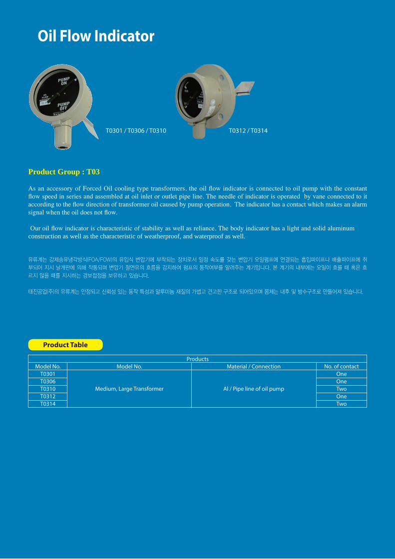
Application : Oil level indication of small transformerAssembly : Tank cover
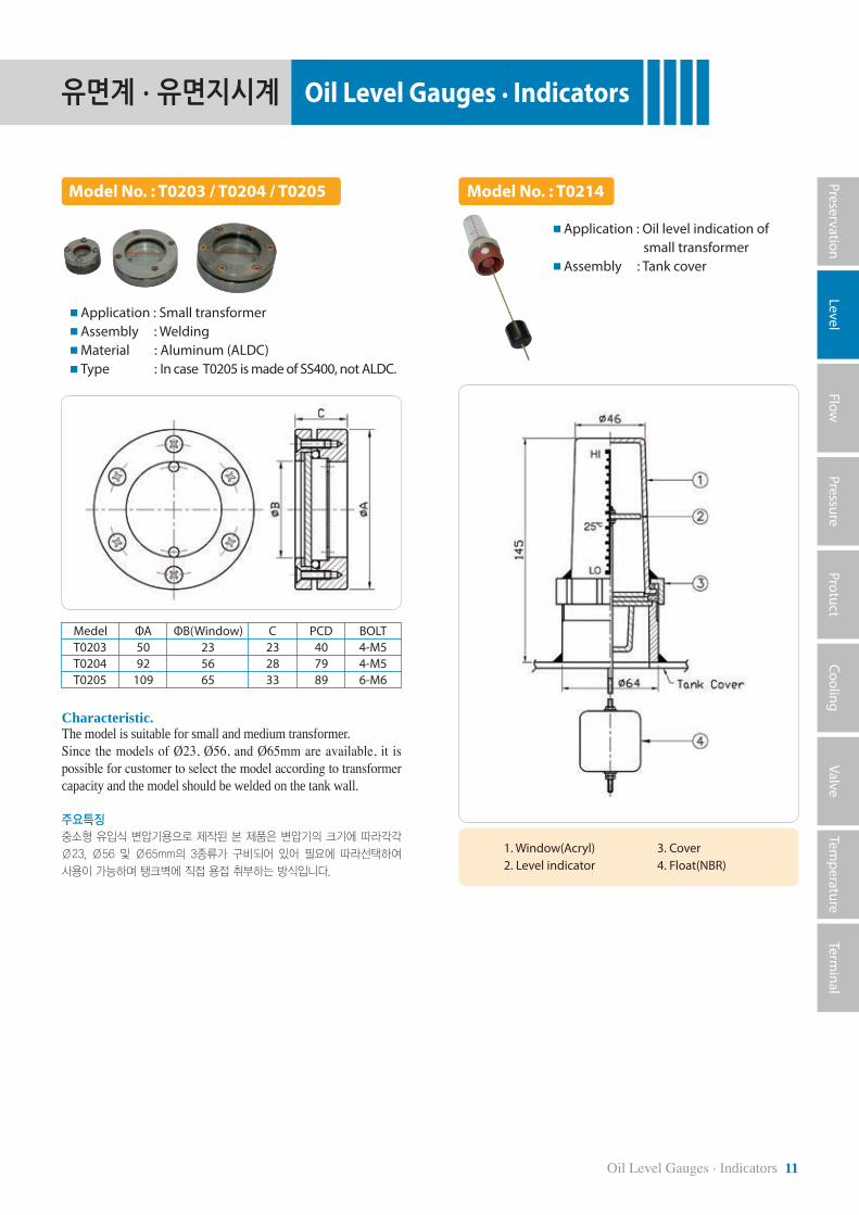
Characteristic. The model is suitable for small and medium transformer.Since the models of Ø23, Ø56, and Ø65mm are available, it is possible for customer to select the model according to transformer capacity and the model should be welded on the tank wall.
주요특징
중소형 유입식 변압기용으로 제작된 본 제품은 변압기의 크기에 따라각각
Ø23, Ø56 및 Ø65mm의 3종류가 구비되어 있어 필요에 따라선택하여
사용이 가능하며 탱크벽에 직접 용접 취부하는 방식입니다.
Model No. : T0203 / T0204 / T0205 Model No. : T0214
Application : Small transformerAssembly : WeldingMaterial : Aluminum (ALDC)Type : In case T0205 is made of SS400, not ALDC.
1. Window(Acryl)2. Level indicator
3. Cover4. Float(NBR)
Medel ΦA ΦB(Window) C PCD BOLTT0203T0204T0205
5092
109
232833
407989
4-M54-M56-M6
235665

12 Oil Level Gauges . Indicators
유면계 . 유면지시계 Oil Level Gauges . Indicators
Characteristic. The model is magnetic type oil level indicator for small transformer and assembled on transformer tank or conservator.The model is characteristic of waterproof and shockproof, can be used for all transformers filled with mineral or less flammable oil and check the variation of oil level inside the transformer including the nominal oil level of 25 ºC. The needle of the model indicates the oil level by means of connecting it to a buoy.
주요특징
본 소형 유입식 변압기용 자석식의 유면지시계는 탱크 또는 콘서베이터 유
면 표시용으로 사용되며, 방수 . 내충격형으로서 일반 절연유 및 불연성 절
연유 모두에 사용할 수 있으며 25℃의 정상유면의 변동상태를 알 수있습
니다. 유면 위치는 부표에 연결된 지침에 의하여 표시됩니다.
Model No. : T0206 Model No. : T0208
Application : Oil level indication of small transformer Assembly : BoltingOperation : Magnetic typeMaterial : Aluminum (ALDC)Type : Ø70 / Without contact
Application : Oil level indication of medium transformer Assembly : Separate type flange Operation : Magnetic typeMaterial : Aluminum (ALDC)Type : Ø120 / 1, 2 contacts
1. Front cover 2. Float 3. Arm 4. Body
Characteristic. The model is characteristic of waterproof and shockproof, can be used for all transformers filled with mineral or less flammable oil and check the variation of oil level inside the transformer including the nominal oil level of 25 ºC.The needle of the model indicates the oil level by means of connecting it to a buoy and the model will make alarm signal when the oil level reaches a setting value such as lower level.
Option The face mark of the model can be changed by the temperature of 25 / 30 or 35 ºC as an option–H as well as contact mark-G such as high and/or low. 주요특징본 자석식 유면계는 탱크 또는 콘서베이터의 유면 표시용으로 사용되며, 방수 . 내충격형으로서 일반절연유 및 불연성절연유 모두에 사용할 수 있으며 정상유면의 변동상태를 알 수 있습니다. 유면 위치는 부표에 연결된 지침에 의하여 표시되며 저유면 경보장치를 동작시킬 수 있는 접점이 구비되어 있습니다.
※ 선택사양 : 문자판변경(온도범위선택 25/30/35)-H
접점(접점표기선택)-G
Voltage Resistance Load(Amps) Inductive Load(Amps)125AC250AC125DC250DC
55
0.50.25
33
0.050.025
Micro Switch Capacity
When circuit diagram is normal oil level

PreservationLevel
FlowPressure
ProtuctCooling
ValveTem
peratureTerm
inal
Oil Level Gauges . Indicators 13
유면계 . 유면지시계 Oil Level Gauges . Indicators
Model No. : T0271 Model No. : T0276
Application : Oil level indication and temperature of small transformer Assembly : BoltingOperation : Float and Bimetal typeMaterial : SUS 304Type : Ø110 / Without contact
Application : Oil level indication of medium transformer Assembly : Separate type flange Operation : Magnetic type w/cont.Material : Aluminum (ALDC)Type : Ø120 / 1, 2 contact
Characteristic. As an economic type products, functions of both T0214Cup oil level indicator and T1101 bimetal temperature are combined into model No. T0271. 주요특징
유면온도계는 T0214 컵 유면계와 T1101 바이 메탈식 온도계를 결합한 경
제적인 제품입니다.
G. No. L AG01G02
380335
15094
1. Body 2. Back flange 4. Gear Ass’y 5. Float Ass’y.
3. Extension pipe
Characteristic. The Function of the model is same as that of Model No. T0208. When it is difficult to check the oil level due to fire wall between transformers, the model is suitable for checking the oil level in front of the conservator because the model is level up gear type even though conventional type oil level indicator is generally installed on the side wall of conservator.
주요특징
본 제품의 기능은 Conservator 측면 취부용 Model No. T0208과 동일하나
측면의 벽과의 거리가 좁아 관찰이 용이 하지 않을시 Conservator의 정면
에서 관찰 할 수있는 Level Up된 Gear Type 유면계입니다.
Voltage Resistance Load(Amps) Inductive Load(Amps)125AC250AC125DC250DC
55
0.50.25
33
0.050.025
Micro Switch Capacity
When circuit diagram is normal oil level
2 Contacts1 Contact

14 Oil Level Gauges . Indicators
유면계 . 유면지시계 Oil Level Gauges . Indicators
Model No. : T0212 / T0281 Model No. : T0213 / T0215 / T0280
Application : Oil level indicator for medium and large transformer Assembly : Bolting Operation : Magnetic type Material : Aluminum (ALDC) Type : T0212(Ø210 / Contact) T0281(Ø250 / Contact)
Application : Oil level indicator for medium and large transformer Assembly : Flange type Operation : Magnetic type including a contact Material : Aluminum (ALDC) Type : T0213(Ø210 / Contact, for AP type) T0215(Ø210 / Contact for FN type)T0280(Ø250 / Contact for FN type)
1. Body2. Flange3. Front cover4. Glass5. Dial Plate
6. Micro switch7. Terminal box8. Terminal9. Bevel gear 10. Spur gear
11. Cover12. Axial13. Float ass'y
• Max. Angle : 70° • Min. Angle : 70°
1. Body2. Flange3. Front cover4. Glass
5. Dial Plate6. Micro switch7. Terminal box 8. Terminal
9. Universal joint10. Axial11. Back body12. Float ass'y
Characteristic. The Model is suitable for indicating the oil level of power transformer filled with all kinds of oil and has the characteristic of waterproof, shockproof and alarm contacts. The needle of the model indicates the oil level by means of connecting it to a Float ass'y and the model has an alarm contact.
Option changeable Face color and face letter / addable Contact 주요특징본 자석식 유면지시계는 주로 콘서 베이터의 유면을 표시하기 위하여 사용되며, 방수 . 내충격형으로서 일반 . 불연성 절연유 모두에 사용이 가능합니다. 유면의 위치는 부표에 연결된 지침에 의해 표시되며 경보장치를 동작시킬 수 있는 접점이 구비되어 있습니다.
※ 선택사양 : 문자판 . 색상변경 / 접점추가
Model ØA ØB PCD C ØC E F G Packing homeT0213T0215T0280
140--
164--
180150150
210180180
121010
3.5--
40--
OXX
Characteristic. The Model is suitable for indicating the oil level of power transformer and is characteristic of waterproof, shockproof and has an alarm contact. The model is nearly maintenance free because of assembling it to the conservator during transportation.
OptionFace color / letter / Angle / Contact 주요특징본 자석식 유면지시계는 대형 유입식변압기의 유면표시를 위하여 사용되
며, 방수 . 내충격형으로서 경보접점을 구비하고 있습니다. 보통 변압기나
관련된 장치에 부착되어 수송되며 보수가 거의 필요 없습니다.
※선택사양 : 색상변경 / 각도 / 접점 / 문자판
Oil Flow Indicator
Product Group : T03
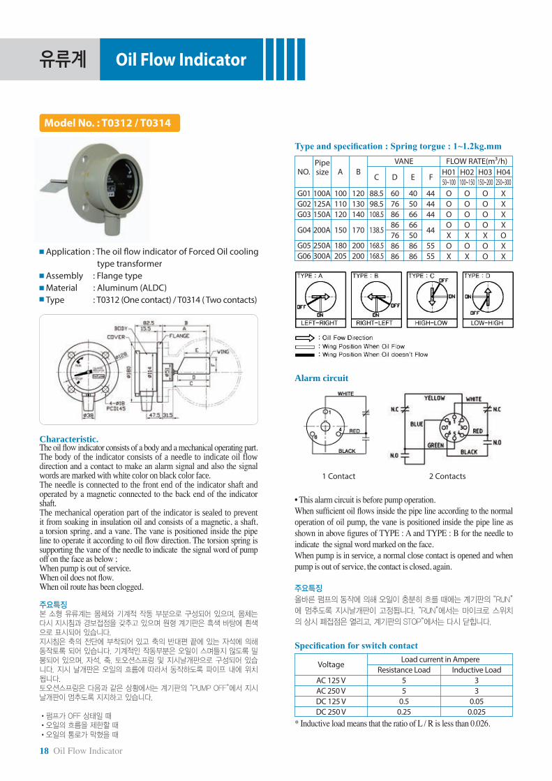
As an accessory of Forced Oil cooling type transformers, the oil flow indicator is connected to oil pump with the constant flow speed in series and assembled at oil inlet or outlet pipe line. The needle of indicator is operated by vane connected to it according to the flow direction of transformer oil caused by pump operation. The indicator has a contact which makes an alarm signal when the oil does not flow.
Our oil flow indicator is characteristic of stability as well as reliance. The body indicator has a light and solid aluminum construction as well as the characteristic of weatherproof, and waterproof as well.
유류계는 강제송유냉각방식(FOA/FOW)의 유입식 변압기에 부착되는 장치로서 일정 속도를 갖는 변압기 오일펌프에 연결되는 흡입파이프나 배출파이프에 취
부되어 지시 날개판에 의해 작동되며 변압기 절연유의 흐름을 감지하여 펌프의 동작여부를 알려주는 계기입니다. 본 계기의 내부에는 오일이 흐를 때 혹은 흐
르지 않을 때를 지시하는 경보접점을 보유하고 있습니다.
태진공업(주)의 유류계는 안정되고 신뢰성 있는 동작 특성과 알루미늄 재질의 가볍고 견고한 구조로 되어있으며 몸체는 내후 및 방수구조로 만들어져 있습니다.
Product Table
ProductsModel No.
T0301T0306T0310T0312T0314
Model No. Material / Connection
Medium, Large Transformer Al / Pipe line of oil pump
No. of contactOne One TwoOne Two
T0301 / T0306 / T0310 T0312 / T0314

유류계
16 Oil Flow Indicator
Oil Flow Indicator
Characteristic. The oil flow indicator consists of body and mechanical operating part.The body of indicator consists of a needle to indicate oil flow direction, a contact to make an alarm signal and signal words are marked with white color on black color face.The needle is connected to the front end of the indicator shaft and operated by a magnetic connected to the back end of the indicator shaft. The mechanical operation part of the indicator is sealed to prevent it from soaking in insulation oil and consists of a magnetic, a shaft, a torsion spring and a vane. The vane is positioned inside the pipe line to indicate a signal word according to oil flow direction. The torsion spring is supporting the vane of the needle to indicate the signal word of pump off on the Face as below ; When pump is out of service.When oil does not flow.When oil route has been clogged. 주요특징본 소형 유류계는 몸체와 기계적 작동 부분으로 구성되어 있으며, 몸체는 다시 지시침과 경보접점을 갖추고 있으며 원형 계기판은 흑색 바탕에 흰색으로 표시되어 있습니다.지시침은 축의 전단에 부착되어 있고 축의 반대편 끝에 있는 자석에 의해 동작토록 되어 있습니다. 기계적인 작동부분은 오일이 스며들지 않도록 밀봉되어 있으며, 자석,축, 토오션스프링 및 지시날개판으로 구성되어 있습니다. 지시 날개판은 오일의 흐름에 따라서 동작하도록 파이프 내에 위치됩니다.토오션스프링은 다음과 같은 상황에서는 계기판의 “PUMP OFF”에서 지시날개판이 멈추도록 지지하고 있습니다.
•펌프가 OFF 상태일 때•오일의 흐름을 제한할 때
•오일의 통로가 막혔을 때
Model No. : T0301
Application : The oil flow indicator of Forced Oil cooling type transformers Assembly : Flange typeMaterial : Aluminum (ALDC)
"A" Type
The flow direction of oil. Vane position when oil flows. Vane position when oil does not flow.
The flow direction of oil.Vane position when oil flows.Vane position when oil does not flow.
Alarm circuitWhen sufficient oil flows inside the pipe line according to the normal operation of oil pump, the vane is positioned inside the pipe line as shown in above figures of TYPE : A and TYPE : B for the needle to indicate the signal word marked on the face.When pump is in service, a normal close contact is opened and when pump is out of service, the contact is closed, again. • This alarm circuit is before pump operation.
주요특징
올바른 펌프의 동작에 의해 오일이 충분히 흐를 때에는 계기판의 “PUMP ON”에 멈추도록 지시날개판이 고정됩니다. “PUMP ON”에서는 마이크로 스위치의 상시 폐접점은 열리고, 계기판의 “PUMP OFF”에서는
다시 닫힙니다.
G No.Type ØA B C Vane PipeG01G02G03G04G05G06G07G08G01G02G03G04G05G06G07G08
ABCDABCDABCDABCD
183 71 406"
8"HD
163 51 40 4"
HS
183 71 40 -
183 71 40 -
Type and specification : Spring torgue : 1~1.2kg.mm
Specification for switch contact
Voltage Load current in Ampere
Resistance Load55
0.50.25
AC 125 VAC 250 VDC 125 VDC 250 V
Inductive Load33
0.050.025
* Inductive load means that the ratio of L / R is less than 0.026.
"B·C·D" Type

유류계
PreservationLevel
FlowPressure
ProtuctCooling
ValveTem
peratureTerm
inal
Oil Flow Indicator 17
Oil Flow Indicator
Characteristic. The oil flow indicator consists of a body and a mechanical operating part.The body of the indicator consists of a needle to indicate oil flow direction and a contact to make alarm signal and also the signal words are marked with white color on black color face.The needle is connected to the front end of the indicator shaft and operated by a magnetic connected to the back end of the indicator shaft. The mechanical operation part of the indicator is sealed to prevent it from soaking in insulation oil and consists of a magnetic, a shaft, a torsion spring, and a vane. The vane is positioned inside the pipe line to operate it according to oil flow direction. The torsion spring is supporting the vane of the needle to indicate the signal word of pump off on the face as below ; When pump is out of service.When oil does not flow.When oil route has been clogged. 주요특징본 소형 유류계는 몸체와 기계적 작동 부분으로 구성되어 있으며, 몸체는 다시 지시침과 경보접점을 갖추고 있으며 원형 계기판은 흑색 바탕에 흰색으로 표시되어 있습니다.지시침은 축의 전단에 부착되어 있고 축의 반대편 끝에 있는 자석에 의해 동작토록 되어 있습니다. 기계적인 작동부분은 오일이 스며들지 않도록 밀봉되어 있으며, 자석, 축, 토오션스프링 및 지시날개판으로 구성되어 있습니다. 지시 날개판은 오일의 흐름에 따라서 동작하도록 파이프 내에 위치됩니다.토오션스프링은 다음과 같은 상황에서는 계기판의 “PUMP OFF”에서 지시날개판이 멈추도록 지지하고 있습니다.
•펌프가 OFF 상태일 때•오일의 흐름을 제한할 때•오일의 통로가 막혔을 때
Model No. : T0306 / T0310
Application : The oil flow indicator of Forced Oil cooling type transformer Assembly : Flange typeMaterial : Aluminum (ALDC) Type : T0306 (One contact) / T0310 (Two contacts)
Type and specification : Spring torgue : 1~1.2kg.mmØANo. B C D Vane Pipe
G01G02G03G04G05G06G07G08G09G10G11G12
ABCDABCDABCD
100212 86 666"
8"
115227 86 66 10"
51163 30 30 4"
"A" Type
Alarm circuit
• This alarm circuit is before pump operation.When sufficient oil flows inside the pipe line according to the normal operation of oil pump, the vane is positioned inside the pipe line as shown in above figures of TYPE : A and TYPE : B for the needle to indicate the signal word marked on the face.When pump is in service, a normal close contact is opened and when pump is out of service, the contact is closed, again.
주요특징올바른 펌프의 동작에 의해 오일이 충분히 흐를 때에는 계기판의 “PUMP
ON”에 멈추도록 지시날개판이 고정됩니다. “PUMP ON”에서는 마이크로 스
위치의 상시 폐접점은 열리고, 계기판의 “PUMP OFF”에서는 다시 닫힙니다.
Specification for switch contact
Voltage Load current in Ampere
Resistance Load55
0.50.25
AC 125 VAC 250 VDC 125 VDC 250 V
Inductive Load33
0.050.025
* Inductive load means that the ratio of L / R is less than 0.026.
The flow direction of oil.Vane position when oil flows.Vane position when oil does not flow.
The flow direction of oil. Vane position when oil flows. Vane position when oil does not flow.
1 Contact 2 Contacts
"B, C, D" Type
유류계
18 Oil Flow Indicator
Oil Flow Indicator
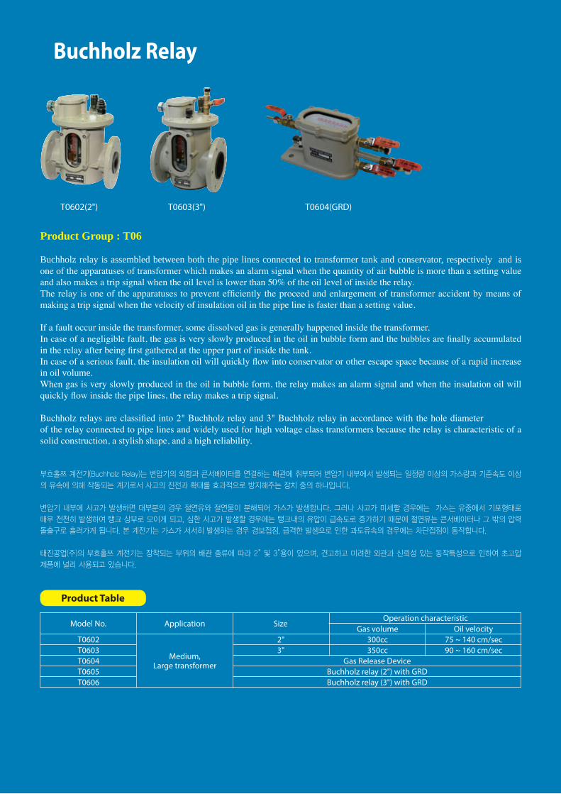
Model No. : T0312 / T0314
Application : The oil flow indicator of Forced Oil cooling type transformer Assembly : Flange typeMaterial : Aluminum (ALDC) Type : T0312 (One contact) / T0314 ( Two contacts)
Type and specification : Spring torgue : 1~1.2kg.mm
Characteristic. The oil flow indicator consists of a body and a mechanical operating part.The body of the indicator consists of a needle to indicate oil flow direction and a contact to make an alarm signal and also the signal words are marked with white color on black color face.The needle is connected to the front end of the indicator shaft and operated by a magnetic connected to the back end of the indicator shaft. The mechanical operation part of the indicator is sealed to prevent it from soaking in insulation oil and consists of a magnetic, a shaft, a torsion spring, and a vane. The vane is positioned inside the pipe line to operate it according to oil flow direction. The torsion spring is supporting the vane of the needle to indicate the signal word of pump off on the face as below ; When pump is out of service.When oil does not flow.When oil route has been clogged. 주요특징본 소형 유류계는 몸체와 기계적 작동 부분으로 구성되어 있으며, 몸체는 다시 지시침과 경보접점을 갖추고 있으며 원형 계기판은 흑색 바탕에 흰색으로 표시되어 있습니다.지시침은 축의 전단에 부착되어 있고 축의 반대편 끝에 있는 자석에 의해 동작토록 되어 있습니다. 기계적인 작동부분은 오일이 스며들지 않도록 밀봉되어 있으며, 자석, 축, 토오션스프링 및 지시날개판으로 구성되어 있습니다. 지시 날개판은 오일의 흐름에 따라서 동작하도록 파이프 내에 위치됩니다.토오션스프링은 다음과 같은 상황에서는 계기판의 “PUMP OFF”에서 지시날개판이 멈추도록 지지하고 있습니다.
•펌프가 OFF 상태일 때•오일의 흐름을 제한할 때•오일의 통로가 막혔을 때
NO.Pipe size A B
VANE
C D E F H0150~100
H02100~150
H03150~200
H04250~300
FLOW RATE(m3/h)
G01G02G03
G05G06
G04
100A125A150A
250A300A
200A
100110120
180205
150
120130140
200200
170
88.598.5108.5
168.5168.5
138.5
60768686768686
40506666508686
OOOOXOX
OOOOXOX
OOOOXOO
XXXXOXX
444444
5555
44
Alarm circuit
• This alarm circuit is before pump operation.When sufficient oil flows inside the pipe line according to the normal operation of oil pump, the vane is positioned inside the pipe line as shown in above figures of TYPE : A and TYPE : B for the needle to indicate the signal word marked on the face.When pump is in service, a normal close contact is opened and when pump is out of service, the contact is closed, again.
주요특징
올바른 펌프의 동작에 의해 오일이 충분히 흐를 때에는 계기판의 “RUN”
에 멈추도록 지시날개판이 고정됩니다. “RUN”에서는 마이크로 스위치
의 상시 폐접점은 열리고, 계기판의 STOP”에서는 다시 닫힙니다.
Specification for switch contact
Voltage Load current in Ampere
Resistance Load55
0.50.25
AC 125 VAC 250 VDC 125 VDC 250 V
Inductive Load33
0.050.025
* Inductive load means that the ratio of L / R is less than 0.026.
1 Contact 2 Contacts

Pressure Relief Device
Product Group ; T05, T04
Pressure Relief Device (PRD) or Pressure relief Valve (PRV) is assembled on transformer tank.The PRD or PRV is one of the essential apparatuses of transformer when an abnormal pressure caused by internal fault occur inside the tank or the pressure inside the tank is higher than the operation pressure of the PRD or PRV, the diaphragm of the PRD or PRV will be lifted up by the abnormal pressure to protect the tank from damage.
PRD and PRV are manufactured to withstand frequent operations and have a solid construction and a high reliability as a sealing apparatus.
We have various and wide PRD and PRV such as PRV (T0401 ~ T0403) for relieving an abnormal pressure from oil immersed small transformer tank, PRD (T0501 ~ T0505) for oil immersed medium transformer tank, and PRD (T0506, T0510) for oil immersed medium or large transformer tank. The quality and excellence of .. PRD and PRV have been proven by selling them to famous transformer manufacturers in the world market for about 20 years.
방출안전장치(PRD) 및 방압변(PRV)는 변압기의 외함(Tank)에 취부되어 변압기 내부에서 사고로 인한 이상압력이 발생, 일정압력을 초과할 때 방압막
(Diaphragm)이 동작하여 변압기 외함의 변형이나 파손을 막아 주는 장치로서 변압기의 가장 기본이 되는 필수 장치 중의 하나입니다.
태진공업(주)의 방출안전장치 및 방압변은 견고한 구조와 완벽한 밀봉장치로써 높은 신뢰성을 보유하고 있고 빈번한 동작에도 충분히 견디도록 강하게 제작되어
있습니다.
소형 유입식 변압기의 이상압력 방출용인 방압변(T0401~T0403)과 중소형 변압기용 방압안전장치(T0501~T0504) 및 중대형 유입식 변압기용 방출안전장치
(T0506, T0510)에 이르기까지 다양하고 폭 넓는 사양을 구비하고 있으며, 20여년간 국내외 유수한 변압기 업체에 본 제품이 널리 공급되어 그 우수성과 신뢰성
이 입증된 제품 중의 하나입니다.
Product Table
Model No. Application Dia / Operation pressure Contact RemarksT0501T0502T0503T0504T0506T0510T0401T0402T0403
Small, Mediumtransformer
Medium, Large transformer
Small transformer
Ø90 / 0.7 ± 0.07kg/cm2Ø90 / 0.7 ± 0.07kg/cm2
Ø120 / 0.7 ± 0.07kg/cm2Ø120 / 0.7 ± 0.07kg/cm2Ø175 / 0.7 ± 0.07kg/cm2Ø175 / 0.7 ± 0.07kg/cm2
Ø9 / 0.7 ± 0.14kg/cm2Ø20 / 0.7 ± 0.14kg/cm2Ø32 / 0.7 ± 0.14kg/cm2
XOXOOOXXX
Flange on both side
Air vent type
T0501(Ø90) / T0502(Ø90)T0503(Ø120) / T0504(Ø120)
T0401 / T0402 / T0403T0506 / T0510(Air Vent Type) T0521~4
Caution!Do not install all P, R, D at side wall of the transformer for right operating and protection from rainwater.
주의!모든 PRD는 올바른 동작 및 빗물로 부터의 보호를 위하여 변압기의 측면에 취부하지 말것.

20 Pressure Relief Device
방압안전장치 Pressure Relief Device
Model No. : T0501~T0504
Application : Small, Medium transformer. Assembly : Flange type.Material : Aluminum (ALDC)
T0501
1. Body 2. Diaphragm 3. Axle 4. Cover
T0502
1. Body 2. Diaphragm 3. Axle 4. Cover
5. Micro S/W 6. Terminal block 7. Cable gland
Characteristic. The models of Pressure Relief Devices for small and medium transformers are usually assembled on transformer cover and are one of transformer devices which can be suitably operated under always leaving them outdoor and also are perfectly protected from oil leakage as well as moisture permeation.We have prepared various Pressure Relief Devices for customers to select them according to their various requirements.The devices have a certain operation characteristic and are not effected by any vibration because of the solid construction of devices.
Operation pressure ; 0.7 ± 0.07 kg/cm2 as standard value. 주요특징
본 중소형 유입식 변압기용의 방압안전장치는 주로 변압기 탱크 카바에 취
부되며 옥외에 상시 방치되는 조건 하에서도 원활하게 동작하는 계기로서,
누유 및 습기의 침투가 없습니다. 또한 다양한 직경과 소요접점에 따라 선
택하여 사용할 수 있도록 되어 있습니다. 동작특성이 확실하며 신뢰성 있
는 구조로서 진동 등에도 거의 영향을 받지 않습니다.
동작기준압력치 : 0.7±0.07 kg/㎠ (당사표준)
T0503
T0504
1. Body 2. Cover 3. Diaphragm 4. Axle
1. Body 2. Diaphragm 3. Axle 4. Cover
5. Micro S/W 6. Terminal block 7. Cable gland
Contact and Dia.
Micro Switch Capacity
Model
Voltage Resistance Load(Amps)
Inductive Load(Amps)
T0501
Ø90 Ø120
T0502 T0503 T0504Contact
Dia
125AC250AC125DC250DC
55
0.50.25
33
0.050.025
X O X O

PreservationLevel
FlowPressure
ProtuctCooling
ValveTem
peratureTerm
inal
Pressure Relief Device 21
방출안전장치 Pressure Relief Device
Characteristic. The model of Pressure Relief Device for medium or large transformer is usually assembled on transformer cover and is one of transformer devices which can be suitably operated under always leaving it outdoor and also is perfectly protected from oil leakage as well as moisture permeation.Even though the model is subjected to frequent operations, the model withstands well because the model has a solid construction.The operation part of the model consists of an operating disk, springs, a gasket, and a protection cover.The indicating pin of the model is made of light aluminum and put on the top of operation disk.When the operating disk is lifted up by an abnormal pressure, the indicating pin is also lifted up by the operating disk and the alarm contactor is operated.
According to customer’s requesting, an alarm device can be fitted to the cover side wall of the model and consists of a normal open contact and a normal close contact.When the device is operated, the normal close contact will be open and is generally used for a trip signal. 주요특징본 중대형 유입식 변압기용의 방출안전장치는 주로 변압기 탱크 카바에 취
부되며 옥외 상시 방치되는 조건 하에서도 원활하게 동작하는 계기로서,
누유 및 습기의 침투가 없습니다.
본 제품의 견고한 구조는 빈번한 동작에도 손상되지 않고 충분히 견디도
록 강하게 만들어져 있고 동작부분은 동작디스크, 압축 스프링, 가스켓과
보호 카바로 구성되어 있습니다. 본 장치의 동작표시는 가벼운 알루미늄제
동작상태 지시봉을 갖고 있는데 이는 동작디스크 상부에 꽂혀 있습니다.
동작디스크가 상부로 동작되는 동안 이 동작상태 지시봉을 상부로 올려 장
치의 동작을 표시하며 또한 경보접점장치(Alarm Contacts) 역시 동작을 표
시하며 접점을 동작시키게 됩니다.
경보접점은 주문시에 카바의 옆에 부착시키며 이 구조는 일반적인 개방 .
폐쇄 구조로 되어 있습니다. 이것이 동작할 때 스위치 버튼이 폐쇄상태에
서 개방상태로 동작되며 주로 트립(Trip)접점으로 활용됩니다.
T0510(Air Vent Hole) Characteristic. The up graded model is same as those of Model No. T0506 and has additionally an air vent hole to release residual air which can be accumulated under the operating disk of the model during filling inside the transformer with insulation oil. 주요특징본 제품은 Model No. T0506과 동일하며 잔류된 Air를 배출시키기 위하여
Air Vent Hole을 설치한 Level Up된 제품입니다. Air Vent Hole 설치로 O.T
주입시 동작디스크 내측 상부에 잔류된 Air를 배출할 수 있는 구조임.
Model No. : T0506 / T0510
Application : Medium or Large transformer Assembly : Flange typeMaterial : Aluminum (grauity casting) Type : T0506 / T0510 (Air Vent Hole)
Construction and name
Operation pressure 0.7 ± 0.07 kg / cm2 (Standard) Contact
a) Contact #1 NC, #2 NO • When operating Operation diskb) Contact #2 NC, #1 NO • When resetting Manually return from b) to a)
• Wiring Diagram
Micro Switch CapacityVoltage Resistance Load(Amps) Inductive Load(Amps)125AC250AC125DC250DC
55
0.50.25
33
0.050.025
1. Flange 2. Gasket 3. Operation disk 4. Gasket
5. Gasket 6. Protection cover 7. Springs8. Indicating pin
9. Alarm device 10. Reset arm11. Air vent hole (Only T0510)

22 Pressure Relief Device
Model No. : T0521~4
방출안전장치 P.R.D. Housing Ass'y
Description Housing for Pressure Relief Devices is designed to direct the spray of oil and gas should the Pressure Relief Device operate. It provides a full 360° rotation for complete flexibility in directing the spray. The compact geometry facilitates retrofit in even the tightest quarters and the included base provides a consistent sealing surface regardless of tank mounting flange size. To install the housing the PRD is removed and the base is placed between it and the mounting flange. The base is vented to allow for drainage of moisture. The housing is used the square flange with 4inchs standard pipe for ductwork. The pipe should be supported separately. The use of die casting aluminum assures durability and resistance to the temperature and pressure of the oil. A bright red indicator is included as standard and provides highly visual indication of PRD operation. 서술
방출안전장치를 위한 태진의 하우징은 방출안전장치 동작시 절연유
및 개스의 분출을 유도하기 위하여 설계되었으며 장착시 360° 회전이
가능하여 분출방향 변경이 가능하다. 완벽한 기하학적 구조는 좁은공
간에서도 설치가 쉽고 포함된 베이스는 탱크 취부 플렌지 크기에 상관
없이 조화된 기밀면을 가진다. 하우징 설치시에 P.R.D를 떼어 낸 다음
베이스를 방출안전장치와 취부 플렌지사이에 안착시킨다.
베이스는 습기의 배출을 위하여 4인치 표준파이프와 4각 플렌지가 사
용된다. 파이프는 단독으로 지지되어야 한다.
알루미늄 주물은 내구성, 내열성 그리고 내유압성을 보증한다. 밝은 적
색 표시기는 표준품으로 포함되어 있고 방출안전장치 동작을 대단히
선명하게 지시한다.
Features• Designed to retrofit easily to. Pressure Relief Devices. • Provides excellent protection against corrosion to the PRD due to environmental conditions.
• Manufactured of rugged cast aluminum to withstand the temperature and pressure of discharge.
• Supplied a top indicator for high visibility of PRD operation.• Ability to rotate 360° for complete flexibility in directing the oil or gas spray.
• Compact geometry provides for field retrofit even in close quarters.• An externally mounted switch is available and provides easy test and reset capability from outside the shield.
• The housing is used the square flange with standard 4" pipe for ductwork to further direct oil spray.
주요특징
•태진의 방출안전장치에 쉽게 장착할 수 있는 구조로 설계되었다.
• 환경요인으로 인한 방출안전장치의 부식방지를 위한 훌륭한 보호
장치이다.
• 온도 및 방출압력에 견딜수 있는 알루미늄 주물로 만들어져 있다.
• 방출안전장치의 동작을 쉽게 알아보기 위한 상부 표시기가 공급된다.
• 절연유 및 개스분출 방향을 완벽하게 조정하기 위하여 360° 회전 장
착이 가능하다.
• 간결한 기하학적 구조는 좁은공간에서도 설치가 가능하다.
• 외부에 설치된 스위치는 외부에서 접점 시험 및 리셋이 가능한 유용
한 구조이다.
• 하우징은 절연유 분출을 유도하는 덕터작업을 위하여 4각플렌지와
4인치 파이프가 사용되었다.
Wiring Diagram
Operation pressure 0.7 ± 0.07 kgf / cm2 (Standard)
Operation :a) Contact #1 normally closed. #2 normally open.b) Contact #2 closes and #1 opens when PRD operates• Manual reset from b to a.
Micro Switch CapacityVoltage Plasistance Lood(Amps) Inductive Lood(Amps)125AC250AC125DC250DC
55
0.50.25
33
0.050.025
#1
#2

PreservationLevel
FlowPressure
ProtuctCooling
ValveTem
peratureTerm
inal
Pressure Relief Device 23
Model No. : T0401 Model No. : T0403
Application : Small transformer. Assembly : Screw type.Material : Brass (Bs). Type : Ø9
Application : Small transformer. Assembly : Screw type.Material : Brass (SUS). Type : Ø32
1. Body(Bs) 3. Axle(Bs) 3. Axle(Bs)2. Cover(Silicom rubber) 4. Handle(SUS)
1. Axle(SUS)2. Nut(SUS)3. Plane washer(SUS)4. Spring(SUS)
5. Body(SUS)6. Cover(SUS)7. Handle(SUS)8. Boss(SS400)
Characteristic. Pressure Relief Valve for small transformer is usually assembled on transformer cover.When abnormal pressure inside the transformer occur, the pressure will be released through the valve and also when the pressure is normal, the valve returns to the original position.It means that the transformer is completely re-sealed from atmosphere.The valve can be chosen by customers according to transformer capacity and easily assembled to transformer tank because the valve is screw type. Operation pressure ; 0.7 ± 0.07 kg/cm2 (when the pressure is higher than 0.45kg/cm2, the valve is automatically re-set).
주요특징본 소형 유입식 변압기용 방압변은 변압기 탱크에 취부되며, 변압기 내부
의 이상압력을 외부로 잘 방출시켜줄 뿐 아니라 일정압력 하에서는 자동
복귀되므로 변압기를 항상 밀폐시키는 구조로 되어 있습니다. 직경의 크기
에 따라 선택할 수 있으며 나사식으로 간편하게 취부할 수 있습니다.
동작압력 : 0.7±0.07 kg/㎠ (복귀압력 : 0.45kg/㎠ 이상)
방압변 Pressure Relief Device
Model No. : T0402
Application : Small transformer. Assembly : Screw type.Material : Brass (Bs). Type : Ø20
1. Axle(Bs)2. Nut(Bs)3. Plane washer(Bs)
4. Body(Bs)5. Cover(Bs)6. Handle(SUS)
24 Pressure Relief Device
Buchholz Relay
Product Group : T06
Buchholz relay is assembled between both the pipe lines connected to transformer tank and conservator, respectively and is one of the apparatuses of transformer which makes an alarm signal when the quantity of air bubble is more than a setting value and also makes a trip signal when the oil level is lower than 50% of the oil level of inside the relay. The relay is one of the apparatuses to prevent efficiently the proceed and enlargement of transformer accident by means of making a trip signal when the velocity of insulation oil in the pipe line is faster than a setting value.
If a fault occur inside the transformer, some dissolved gas is generally happened inside the transformer.In case of a negligible fault, the gas is very slowly produced in the oil in bubble form and the bubbles are finally accumulated in the relay after being first gathered at the upper part of inside the tank.In case of a serious fault, the insulation oil will quickly flow into conservator or other escape space because of a rapid increase in oil volume.When gas is very slowly produced in the oil in bubble form, the relay makes an alarm signal and when the insulation oil will quickly flow inside the pipe lines, the relay makes a trip signal.
Buchholz relays are classified into 2" Buchholz relay and 3" Buchholz relay in accordance with the hole diameter of the relay connected to pipe lines and widely used for high voltage class transformers because the relay is characteristic of a solid construction, a stylish shape, and a high reliability.
부흐홀쯔 계전기(Buchholz Relay)는 변압기의 외함과 콘서베이터를 연결하는 배관에 취부되어 변압기 내부에서 발생되는 일정량 이상의 가스량과 기준속도 이상
의 유속에 의해 작동되는 계기로서 사고의 진전과 확대를 효과적으로 방지해주는 장치 중의 하나입니다.
변압기 내부에 사고가 발생하면 대부분의 경우 절연유와 절연물이 분해되어 가스가 발생합니다. 그러나 사고가 미세할 경우에는 가스는 유중에서 기포형태로
매우 천천히 발생하여 탱크 상부로 모이게 되고, 심한 사고가 발생할 경우에는 탱크내의 유압이 급속도로 증가하기 때문에 절연유는 콘서베이터나 그 밖의 압력
돌출구로 흘러가게 됩니다. 본 계전기는 가스가 서서히 발생하는 경우 경보접점, 급격한 발생으로 인한 과도유속의 경우에는 차단접점이 동작합니다.
태진공업(주)의 부흐홀쯔 계전기는 장착되는 부위의 배관 종류에 따라 2” 및 3”용이 있으며, 견고하고 미려한 외관과 신뢰성 있는 동작특성으로 인하여 초고압
제품에 널리 사용되고 있습니다.
Product Table
Model No. Application Size Operation characteristic
Gas Release DeviceBuchholz relay (2") with GRDBuchholz relay (3") with GRD
Gas volume Oil velocityT0602T0603T0604T0605T0606
Medium,Large transformer
2"3"
300cc350cc
75 ~ 140 cm/sec90 ~ 160 cm/sec
T0602(2") T0603(3") T0604(GRD)

PreservationLevel
FlowPressure
ProtuctCooling
ValveTem
peratureTerm
inal
Buchholz Relay 25
부흐홀쯔계전기 Buchholz Relay
Contact 1 (Alarm contact)When gas is accumulated in the upper part of Buchholz relay after the gas is very slowly produced in the oil in bubble form and the oil level inside the relay is finally dropped to a setting level, the relay makes an alarm signal because the reed switch contact of the relay is closed due to the low position of the buoy of the relay caused by the gas accumulation.
접점 1가스가 서서히 발생하여 계전기함의 상부에 축적되고, 따라서 그 압력으로 유면이 낮아져 상부 부표가 가라앉아 리드(Reed)스위치가 동작해서 경보접점이 닫힙니다.
Contact 2 (Trip contact)When gas is very quickly produced in the oil in bubble form and the velocity of the oil flowed through the connection pipe line is very speedy, the relay makes a trip signal because the reed switch contact of the relay is closed due to the movement of the below buoy of the relay caused by the velocity. If the accumulation volume of gas or air is negligible and the gas is very slowly produced in the oil in bubble form, the gas or air enter inside the conservator through the connection pipe line and as a result of that, the below buoy of the relay will keep it’s level without falling because the further oil level inside the Buchholz relay will not be dropped. But when oil level inside the relay is lower than the center line of the connection pipe line, the relay makes a trip signal because the below buoy of the relay is slightly dropped from the original level.
접점 2가스가 갑자기 발생할 때는 연결관을 통해 콘서베이터로 들어가는 유속이 빨라져서 하부 부표가 움직여 리드(Reed)스위치가 동작해서 차단접점이 닫힙니다. 만약 가스 혹은 공기의 축적량이 미량이면, 가스나 공기가 연결관의 상단부를 통해 콘서베이터 안으로 들어가게 되고, 따라서 유면은 더이상 낮아지지 않으므로 가스가 서서히 발생할 때는 하부 부표는 동작하지 않습니다. 그러나 만약 유면이 연결관의 중심이하로 내려가면, 하부 부표가 가라앉아 차단 접점을 작동시킵니다.
Return If the oil level or the velocity inside the relay is return to a normal state, the reed switch contact will return to the original position and the buoy as well. 복귀유면이나 유속이 정상 조건으로 복귀하면 리드스위치, 접점(접점 1 및 접점 2)은 부표와 함께 복귀합니다.
Reed switch capacity
Characteristic.The relay consists of a cover, a mechanical part for operating a buoy, two reed switches, two buoys, a fixing apparatus, a body, a test button, an air vent hole, and miscellaneous.The relay is characteristic of having various auxiliary apparatus such as a reed switch protected from vibration, an apparatus for fixing the buoy during transportation, a test button to check if contacts are well operated and etc.
주요특징본 계전기는 카바, 부표를 움직이는 기계적인 요소, 리드(Reed)스위치, 부표고정장치, 외함과 점검버튼 등으로 이루어져 있으며, 진동 시에도 잘 보호될 수 있는 리드(Reed)스위치, 운반 시 부표를 안전하게 고정시키는 장치
및 접점의 동작을 쉽게 접검하는 등의 여러가지 특성을 가지고 있습니다.
Model No. : T0602 / T0603
Application : Medium, Large size transformers Assembly : Flange typeMaterial : FCD45Type : T0602 (2”), T0603(3”)
Contact and Specification.
Operation condition
Model Size A B C D E
T0602T0603
2"3"
242267
186186
140160
110130
5280
250-350300-400
75-14090-160
Alarm when the quantity of air bubble is more than 250-400cc, the relay makes an alarm signal.
when the velocity of insulation oil in the pipe line is faster than 75-160 cm/sec or the oil level is lower than 50% of inside the relay, the relay makes a trip signal.
Gas volume(cc)
Oil velocity(cm /sec)
Trip
Contactor Diagram
Operation mechanism.
Resistance Load( A )
Inductive Load( A )
AC
DC
125V250V30V
125V
21.522
212
1.5

26 Buchholz Relay
부흐홀쯔계전기 Buchholz Relay
B.H-Relay+GRD Operation check point
1. Normal operating conditionsIn upper B.H-Relay and apparatus GRD filled with oil.상부 B.H-Relay와 GRD내부에 oil이 채워진 상태에서
1) V/V⑨⑪⑬ Closed - V/V⑦⑧⑩ Open
2. Test of the alarm switch1) Inject air through the V/V⑫ until the alarm is given.
Alarm Switch가 울릴 때 까지 V/V⑫를 통하여 air를 주입한다.
3. Gas sampling1) Open V/V⑬
2) The gas begins to collect in the apparatus GRD through pipe
between V/V⑧ and V/V⑩.
(The operation can be checked through the inspection window.)
개스는 V/V⑧과 V/V⑩ 사이의 PIPE를 통하여 GRD내 상부에 모이기 시작한다.
(개스가 모이는 것을 inspection window를 통하여 확인 할 수 있습니다.)
3) After gas collection close V/V⑬
개스를 모은후 V/V ⑬ : Close
4) The gas collected in the GRD chamber can either be removed for
examination or released by opening V/V⑪
Gas성분 분석을 위하여 GDR내부의 gas를 V/V⑪을 열어서 채집하거나
혹은 공기 중으로 배출 시킬 수 있다.
5) When all the gas has been removed or released, the oil will start
lowing in the apparatus GRD through pipe between V/V⑧ and V/V⑩
when the apparatus GRD is filled with oil again, reclose V/V⑪.
개스가 전량 제거 혹은 방출 되었을 때, OIL은 V/V ⑧과 V/V ⑩사이의
PIPE를 통하여 GDR내부로 내려오기 시작한다. 다시 GDR내부에 OIL이
충진 되었을 때 V/V ⑪을 잠근다.
4. Oil sampling1) After open V/V⑨ ☞ Oil sampling with open V/V⑬ ☞ Close V/V⑬
and V/V⑨.
V/V⑨를 연후 V/V⑬을 열어 OIL을 채집 후 V/V⑬과 V/V⑨를 잠근다.
5. Must return to the normal operating conditions same above No.1 after actions of above No.2,3,4. 상기의 No.2, 3, 4를 실행 한 후에는 상기 No.1항과 같이 평상시 동작
상태로 되돌여 놓아야 한다.
Model No. : T0604 / T0605 / T0606
Application : Small or Large transformer. Assembly : Flange type.Material : Body (FCD45), GRD (FC20)Type : T0604 (Gas Release Device, GRD). T0605 (T0602 with GRD). T0606 (T0603 with GRD).
Type• T0602 (2”) with GRD (Gas Release Device) : T0605• T0603 (3”) with GRD (Gas Release Device) : T0606
Connection Diagram
1. BODY ASS'Y 2. COVER 3. TERMINAL ASS'Y 4. COUPLING ASS'Y 5. CIRCUIT CHECKING BUTTON6. GAS RELEASE V/V 7. TEST V/V8. GAS TRANSMISSION 9. V/V FOR COLLECTING OIL 10. V/V FOR TESTING THE UPPER FLOAT(ALARM) 11. V/V FOR GAS SAMPLING OR RELEASING 12. SMALL V/V FOR AIR INJECTION 13. OIL DRAIN V/V

PreservationLevel
FlowPressure
ProtuctCooling
ValveTem
peratureTerm
inal
Buchholz Relay 27
Gas detect relay (or Gas Accumulation Indicator) is an apparatus to warn some faults inside the transformer in advance by means of indicating the volume of explosive and/or flammable gas in transformer caused by partial discharge or the thermal ageing of insulation material.
The relay should be assembled at the top edge for easy waching of transformer filled with insulation oil, completely.
가스 검출 계전기(Gas Detector Relay or Gas Accumulation Indicator)는 변압
기 내부의 부분적인 방전 및 절연불량으로 발생하는 악성 가스의 발생량을
눈금으로 나타냄으로써 변압기의 결함을 사전에 경고해 주는 장치입니다.
이 장치는 지상에서 눈금의 관찰이 용이하도록 변압기 상부 가장자리에 설치
되며, 변압기 탱크에 기름이 가득 차는 형의 변압기에만 적용이 가능합니다.
가스검출계전기 Gas Detector Relay
Model No. : T0607
Operation principle.Explosive and/or flammable gas in transformer caused by partial discharge or the thermal ageing of insulation material enter the relay through pipe line after traveling to the upper part of transformer.The needle on the relay face indicates the gas volume accumulated inside the relay in CC ( Cubic Centimeter ) by means of the pressing force of the gas.
When the gas volume is more than 200 CC, the relay will make an alarm signal.
동작원리
변압기 내부 결함으로부터 발생하는 가스는 변압기 상부로 이동하여 파
이프를 통해 G.D.R로 들어가게 됩니다. 그리고 축적된 가스의 힘에 의해
G.D.R 전면에 있는 지시침은 축적된 가스량을 CC로 나타냅니다.
G.D.R Float Chamber에 200CC의 가스가 축적되었을 때, 경보 스위치가
동작하도록 접점을 구성하였습니다.
Switch operation.1) At gas volume of 0 cc, common terminals of 1 and 4 are normal
open, common terminals of 1 and 6 are normal close. 2) At gas volume of 200 cc, common terminals of 1 and 4 are normal
close, common terminals of 1 and 6 are normal open (Gas volume mark of 200 cc has tolerance of ±3º).
3) When gas volume decreases, common terminals of 1 and 4 are open within 35º from the gas volume mark of 200 cc and common terminals of 1 and 6 are close within 35º from the gas volume mark of 200 cc.
Switch 동작
1) 0cc에서 Common 1과 4는 Open, Common 1과 6은 Close.
2) 200cc에서 Common 1과 4는 Close, Common 1과 6은 Open(200cc
Mark Point ±3°).
3) Gas량 감소시 : Common 1과 4는 200cc Point로부터 최대 각도 35°이
내에서 Open되어야 하고, Common 1과 6은 Close되어야 한다.
Specification for switch contact
Micro Switch CapacityVoltage Resistance Load(Amps) Inductive Load(Amps)125AC250AC125DC250DC
55
0.50.25
33
0.050.025
28 Buchholz Relay
가스검출계전기 Gas Detector Relay (G.D.R)
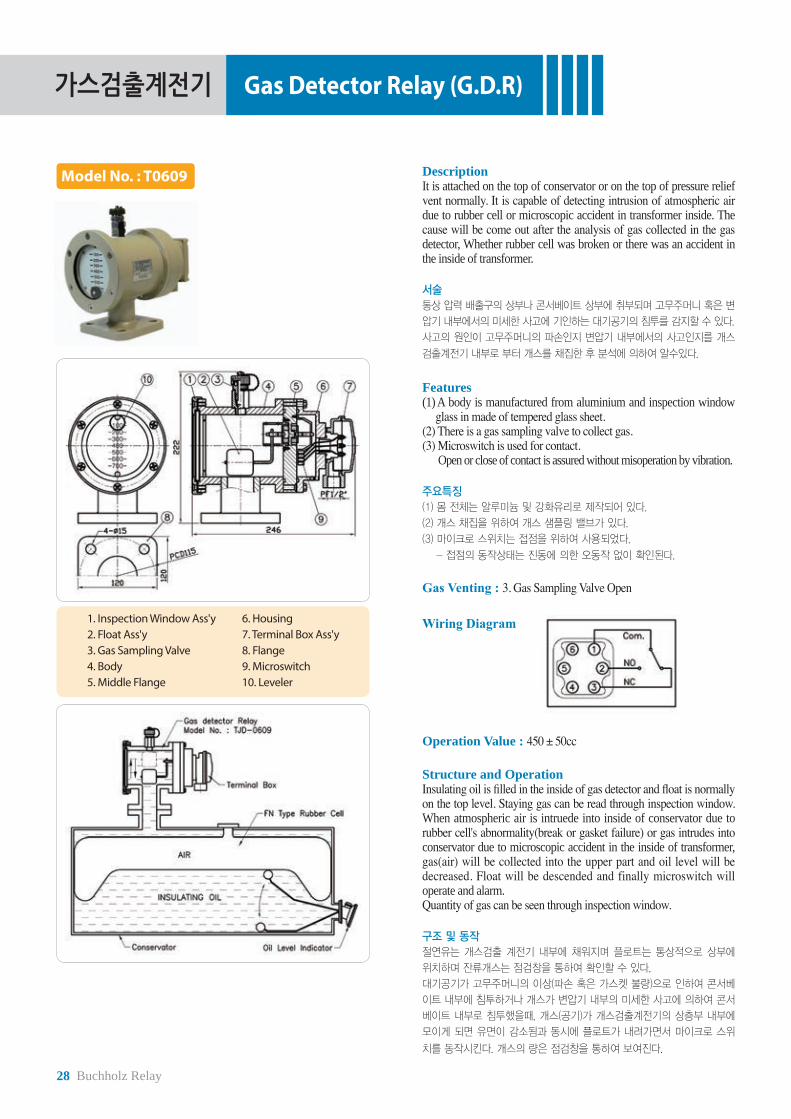
Model No. : T0609 DescriptionIt is attached on the top of conservator or on the top of pressure relief vent normally. It is capable of detecting intrusion of atmospheric air due to rubber cell or microscopic accident in transformer inside. The cause will be come out after the analysis of gas collected in the gas detector, Whether rubber cell was broken or there was an accident in the inside of transformer. 서술
통상 압력 배출구의 상부나 콘서베이트 상부에 취부되며 고무주머니 혹은 변
압기 내부에서의 미세한 사고에 기인하는 대기공기의 침투를 감지할 수 있다.
사고의 원인이 고무주머니의 파손인지 변압기 내부에서의 사고인지를 개스
검출계전기 내부로 부터 개스를 채집한 후 분석에 의하여 알수있다.
Features(1) A body is manufactured from aluminium and inspection window
glass in made of tempered glass sheet.(2) There is a gas sampling valve to collect gas.(3) Microswitch is used for contact. Open or close of contact is assured without misoperation by vibration.
주요특징
(1) 몸 전체는 알루미늄 및 강화유리로 제작되어 있다.
(2) 개스 채집을 위하여 개스 샘플링 밸브가 있다.
(3) 마이크로 스위치는 접점을 위하여 사용되었다.
- 접점의 동작상태는 진동에 의한 오동작 없이 확인된다.
Gas Venting : 3. Gas Sampling Valve Open
1. Inspection Window Ass'y2. Float Ass'y3. Gas Sampling Valve4. Body5. Middle Flange
6. Housing7. Terminal Box Ass'y8. Flange9. Microswitch10. Leveler
Wiring Diagram
Operation Value : 450 ± 50cc
Structure and OperationInsulating oil is filled in the inside of gas detector and float is normally on the top level. Staying gas can be read through inspection window. When atmospheric air is intruede into inside of conservator due to rubber cell's abnormality(break or gasket failure) or gas intrudes into conservator due to microscopic accident in the inside of transformer, gas(air) will be collected into the upper part and oil level will be decreased. Float will be descended and finally microswitch will operate and alarm.Quantity of gas can be seen through inspection window. 구조 및 동작
절연유는 개스검출 계전기 내부에 채워지며 플로트는 통상적으로 상부에
위치하며 잔류개스는 점검창을 통하여 확인할 수 있다.
대기공기가 고무주머니의 이상(파손 혹은 가스켓 불량)으로 인하여 콘서베
이트 내부에 침투하거나 개스가 변압기 내부의 미세한 사고에 의하여 콘서
베이트 내부로 침투했을때, 개스(공기)가 개스검출계전기의 상층부 내부에
모이게 되면 유면이 감소됨과 동시에 플로트가 내려가면서 마이크로 스위
치를 동작시킨다. 개스의 량은 점검창을 통하여 보여진다.

N2 Gas Equipments
Product Group : T09
N2 gas equipment (or N2 gas sealed equipment) is an apparatus to prevent insulation oil from oxidization by means of isolating insulation oil from atmosphere.To attain this purpose, N2 gas is filled above insulation oil level inside the transformer by using the N2 gas equipment.The variation of pressure level or vacuum level inside the transformer, caused by ambient temperature and / or the load change of transformer, can be automatically controlled by the equipment.
In addition to above, the equipment is generally used as an apparatus to supply N2 gas inside the transformer tank during its transportation instead of insulation oil.
N2 gas equipment can be selected and used in accordance with utilization purpose and place. various N2 gas equipments widely used for small power transformers to ultra high voltage class transformers. N2 gas equipment has a good reputation in the world market because the relay is characteristic of a solid construction, a stylish shape, and a high reliability.
질소공급장치 혹은 질소봉입장치는 유입식 변압기 내부의 절연유와 공기의 접촉을 능동적으로 차단하여 절연유에 산소의 유입을 방지함으로써 절연유
의 열화를 방지할 목적으로 변압기 내부 유면 공간에 질소가스를 봉입하기 위한 장치입니다. 탱크 내부의 부하 변동 및 온도 변동으로 인한 압력변화에
따른 탱크압과 진공도는 이 장치로써 자동 조절이 가능합니다.
또한 일부 제품은 변압기의 수송을 위해 절연유 대신 충진되는 질소가스의 공급용 장치로서도 사용됩니다.
태진공업(주)의 질소공급(봉입)장치는 사용되는 목적과 장소에 따라 선택하여 사용할 수 있어 소형 전력용 변압기로부터 초초고압(UHV)의 대형 전력용
변압기 등에도 적용할 수 있도록 다양한 제품군을 보유하고 있으므로 폭넓은 선택의 범위를 제공하고 있을 뿐 아니라 견고한 구조와 미려한 외관으로 국
내 . 외에서 그 제품의 우수성을 인정받고 있습니다.
Product Table
Model No. ApplicationT0901T0902T0903T0904T0906
N2 gas supply apparatus ( Compound gauge ) for small transformer.
N2 gas equipment for transporting transformer.N2 gas equipment for medium, large transformer.N2 gas supply apparatus ( Compound gauge ) for small transformer.
T0901 T0902 T0903
T0904
T0906
30 N2 Gas Equipments
질소봉입장치 N2 Gas Equipments
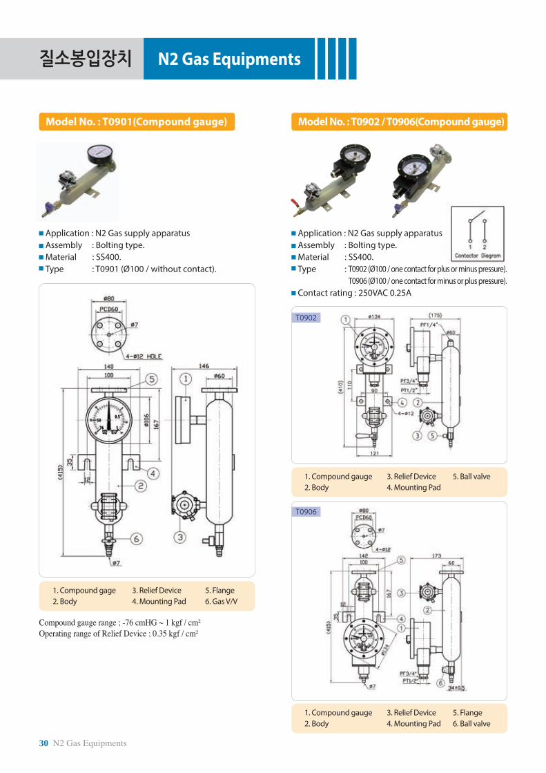
Model No. : T0901(Compound gauge) Model No. : T0902 / T0906(Compound gauge)
Application : N2 Gas supply apparatusAssembly : Bolting type.Material : SS400.Type : T0901 (Ø100 / without contact).
Application : N2 Gas supply apparatusAssembly : Bolting type.Material : SS400.Type : T0902 (Ø100 / one contact for plus or minus pressure). T0906 (Ø100 / one contact for minus or plus pressure).Contact rating : 250VAC 0.25A
1. Compound gage 2. Body
3. Relief Device 4. Mounting Pad
5. Flange6. Gas V/V
Compound gauge range ; -76 cmHG ~ 1 kgf / cm²Operating range of Relief Device ; 0.35 kgf / cm²
1. Compound gauge2. Body
3. Relief Device4. Mounting Pad
5. Ball valve
1. Compound gauge2. Body
3. Relief Device4. Mounting Pad
5. Flange6. Ball valve
T0902
T0906

PreservationLevel
FlowPressure
ProtuctCooling
ValveTem
peratureTerm
inal
N2 Gas Equipments 31
질소봉입장치 N2 Gas Equipments
Application : N2 Gas supply apparatusAssembly : Bolting type.Material : SS400.Type : T0902 (Ø100 / one contact for plus or minus pressure). T0906 (Ø100 / one contact for minus or plus pressure).Contact rating : 250VAC 0.25A
Model No. : T0903 Model No. : T0904
Application : N2 Gas supply apparatusAssembly : Bolting type.Material : SS400.Type : T0903(Transporting type)
Application : N2 Gas supply apparatusAssembly : Bolting type.Material : SS400.Type : T0904(Installation type)
Characteristic. The equipment is an apparatus to prevent insulation oil from oxidization by means of isolating insulation oil from atmosphere. To attain this purpose, N2 gas is filled above insulation oil level inside the transformer by using the N2 gas equipment.The variation of pressure level or vacuum level inside the transformer, caused by ambient temperature and / or the load change of transformer, can be automatically controlled by the equipment.(The equipment is installed inside the moisture proof type cabinet.)
주요특징본 제품은 변압기 내부의 절연유와 공기의 접촉을 차단하여 절연유에 산소
의 유입을 방지함으로써 절연유의 열화를 최소화할 목적으로 변압기 내부
에 질소가스를 봉입하는 장치로서 탱크 내부의 부하 변동 또는 온도 변화
에 기인하는 압력변동에 따른 탱크압 및 진공도를 자동 조절하는 기능을
수행합니다. (본 제품은 방습 처리된 캐비넷 속에 내장되어 있습니다.)
Characteristic. The equipment is an apparatus to feed N2 gas above insulation oil level inside the transformer according to the breathing process of transformer and the N2 gas is automatically supplied by gas bottle with internal pressure of 200 kg / cm² through 2 pressure reducing units.When the N2 gas pressure of the second pressure reducing unit is within 0.03 to 0.35 kg / cm², the equipment keeps to maintain completely sealing state.
주요특징본 제품은 변압기 내부의 유면상의 공간에 질소를 봉입하여 호흡작용에 따
른 질소의 소모를 별개의 용기에서 감압변을 통하여 자동적으로 공급 되도
록 한 장치입니다.
저압력계의 압력이 0.03~0.35kg/㎠ 에서는 질소가스의 출입이 없는 완전
밀폐 상태가 유지됩니다.

ValvesCaution!Do not install all valves in front and back of the oil pump.But you can use valves that are 5, 6, 8 and 10 inches if you have the straight-line distance that is 5~6 times further than the inside diameter of the valve from an exit of the oil pump and elbow pipe.
Product group : T10, T12
Valve is an apparatus used for filling transformer tank with insulation oil, draining oil from transformer tank, or sampling oil and connecting the pipe line to oil immersed transformer. We have prepared various valves widely used for pole transformers to ultra high voltage class transformers because the size and application of valves are variable according to their use purpose and connection position. Our valves have a good reputation in the world market because the valves are characteristic of an unique and solid construction, and a stylish shape.
밸브(Valve)는 유입식 변압기의 배관이나 외함에 취부되어 절연유의 차단이나 배유(Oil Draining) 및 채유(Oil Sampling)에 사용되는 장치입니다.태진공업(주)의 밸브는 그 사용목적과 취부되는 장소에 따라 그 크기와 사양이 다양하여 주상변압기로부터 초초고압(UHV)의 전력용 변압기 등에도 사용할 수 있도록 다양한 제품군을 보유하고 있으므로 폭넓은 선택의 범위를 제공하고 있을 뿐 아니라 태진공업(주) 만의 독특하고 견고한 구조와 미려한 외관으로 국내 . 외에서 그 제품의 우수성을 인정받고 있습니다.
Product Table
Model No. Name Material Size Remarks T1001T1002T1003T1004T1005T1035T1006T1009T1048T1013T1014T1036T1032T1033T1031T1044T1201T1205T1204
Butterfly typeButterfly typeButterfly typeButterfly typeButterfly typeButterfly typeButterfly typeButterfly typeButterfly typeButterfly typeButterfly typeButterfly typeButterfly typeButterfly typeButterfly typeButterfly type
Oil sampling valveOil sampling valve
Oil Inlet cap
ALDC8ALDC8FC20FC20
SS400SS400SS400FC20FC20FC20FC20FC20FC20FC20FC20FC20
BSBS
ALDC8
1.5"2"3"4"3"3"4"4"5"6"8"
10"3"2"4"3"
M16 X 1.5M16 X 1.5
2"
Welding typeWelding typeWelding type
Ø4, smallØ8, large
T1001(1.5") T1002(2") T1003(3")T1004(4")
T1005(3")T1035(3")
T1006(4") T1009(4") T1044(3")
T1033(2") T1031(4")T1032(3")
T1048(5")T1013(6")T1014(8")T1036(10")
T1201(Sampling Valve)
T1205(Sampling Valve)
T1204(Oil inlet cap)
주의!모든 밸브들은 오일 펌프 앞, 뒤에 설치 하지 말 것.그러나 5, 6, 8, 10인치 밸브들은 펌프 및 엘보우 파이프 출구로부터 밸브 내경의 5~6섯배 이상의 충분한 직선 거리가 확보된 후에는 사용 할수 있음.

PreservationLevel
FlowPressure
ProtuctCooling
ValveTem
peratureTerm
inal
Valve 33
밸브 Valve
Model No. : T1001 / T1002 Model No. : T1003 / T1004 / T1044
Application : Connection parts of pipe lines of oil immersed transformer. Assembly : Stud bolt type.Material : Aluminum.Type : T1001(1.5”). / T1002(2”).
Application : Connection parts of pipe lines of oil immersed transformer. Assembly : Stud bolt type.Material : FC20.Type : T1003(3”). / T1004(4”). / T1044(3").
Type A(mm) B(mm) C(mm) D(mm) E(mm) F(mm) G(mm) H(mm) I(mm)T1003(3")T1004(4")T1044(3")
187211187
155179155
150174150
424542
115146126
9812299
9211192
150180160
2828-
T1001 T1003(3") / 1004(4")
T1002 T1044(3")

34 Valve
밸브 Valve
Model No. : T1009
Model No. : T1013 / T1014 / T1036 / T1048
Application : Connection parts of pipe lines of oil immersed transformer. Assembly : Stud bolt type.Material : FC20.Type : T1009(4")
Option ; Stud bolt.
Characteristic. The butterfly valves are mainly used for connecting the radiator head pipe.The unique structure of valves is characteristic of a complete oil leakage proof at the protection cap, body, gate and etc of the valves during the oil leakage test with test pressure of 1.5 kg / cm² and below.
주요특징
본 나비형 밸브는 대형 유입식 변압기의 방열기 배관용으로 주로 사용됩니다.
스프링을 활용한 태진의 고유한 설계 구조는 완벽한 오일의 차단 효과를
가져오며, 1.5kg/㎠ 이하에서의 시험을 거치는 동안 고정캡, 몸통이나
개폐판등 어느 곳에서도 누유가 없는 우수한 제품 입니다.
Application : Connection parts of pipe lines of oil immersed medium, large transformer. Assembly : Stud bolt type.Material : FC20.Type : T1048(5") / T1013(6") T1014(8") / T1036(10")
Type ØA ØB ØC D ØE F G H IT1013/6"T1014/8"
T1036/10"T1048/5"
158206254133
170228285150
200249312171
240280345210
278320385248
285327392255
298340405268
55606055
3444
Option ; Stud bolt.
Caution!Do not install all valves in front and back of the oil pump.But you can use valves that are 5, 6, 8 and 10 inches if you have the straight-line distance that is 5~6 times further than the inside diameter of the valve from an exit of the oil pump and elbow pipe.
T1009
T1048(5")

PreservationLevel
FlowPressure
ProtuctCooling
ValveTem
peratureTerm
inal
Valve 35
밸브 Valve
I No. CI 01I 02
23
Model No. : T1005 / T1006 / T1035
Application : Radiator for oil immersed transformer. Assembly : BoltingMaterial : SS400.Type : T1005(3"), T1006(4"), T1035(3")
Characteristic. Butterfly type radiator valves are welded to transformer tank and characteristic of disassembling radiator from the transformer tank without draining insulation oil from the tank.Prior to transporting transformer tank, the protection cover of the radiator valve should be assembled on the top of radiator valve body to protect the shaft from damage during transportation after closing the gate of valve, draining oil inside the radiator and then disassembling the radiator from the tank.The sealing O-ring fitted in the protection cap of the valve, prevents the valve from the leakage of forging part, forging body, casting protection cap, gate and also protect them from moisture entrance.
주요특징
본 나비형 방열기 밸브는 변압기 내의 기름을 배유시키지 않고 방열기를
제거할 수 있는 구조로서 변압기에 부착되어 있습니다. 변압기를 운송할
때는 먼저 방열기 밸브를 닫고 냉각장치(방열기등)를 분리한 다음, 방열기
밸브에 보호카바를 부착시킵니다.
본 제품은 상부 고정캡 속에 장착된 밀폐 O-Ring과 Forging과 Casting으로
처리된 몸체와 고정캡 및 개폐판은 누유나 습기의 침입을 잘 막아줍니다.
Dimension of reinforcing pipe T1005 (3”)
H No.H01H02H03H04H05H06H07H08H09
L150200250300350400100450
-
A100100100120120150
---
B60
100150200250300
---
RemarksW200W250W300W350W400W450P150P450
Elbow
T1006 (4”)H No.H01H02H03H04H05H06H07H08H09H10
L80
12015017020025030010095
125
A----
100100120
---
B----
100150200
---
T1035 (3”)H No.H01H02H03H04H05H06H07H08H09
L150200250300350400100450150
A100100100120120150
---
B60
100150200250300
---
RemarksN200N250N300N350N400N450B150B450B200
T1005(3")
T1006(4")
T1035(3")
T1006(4")
36 Valve
밸브 Valve
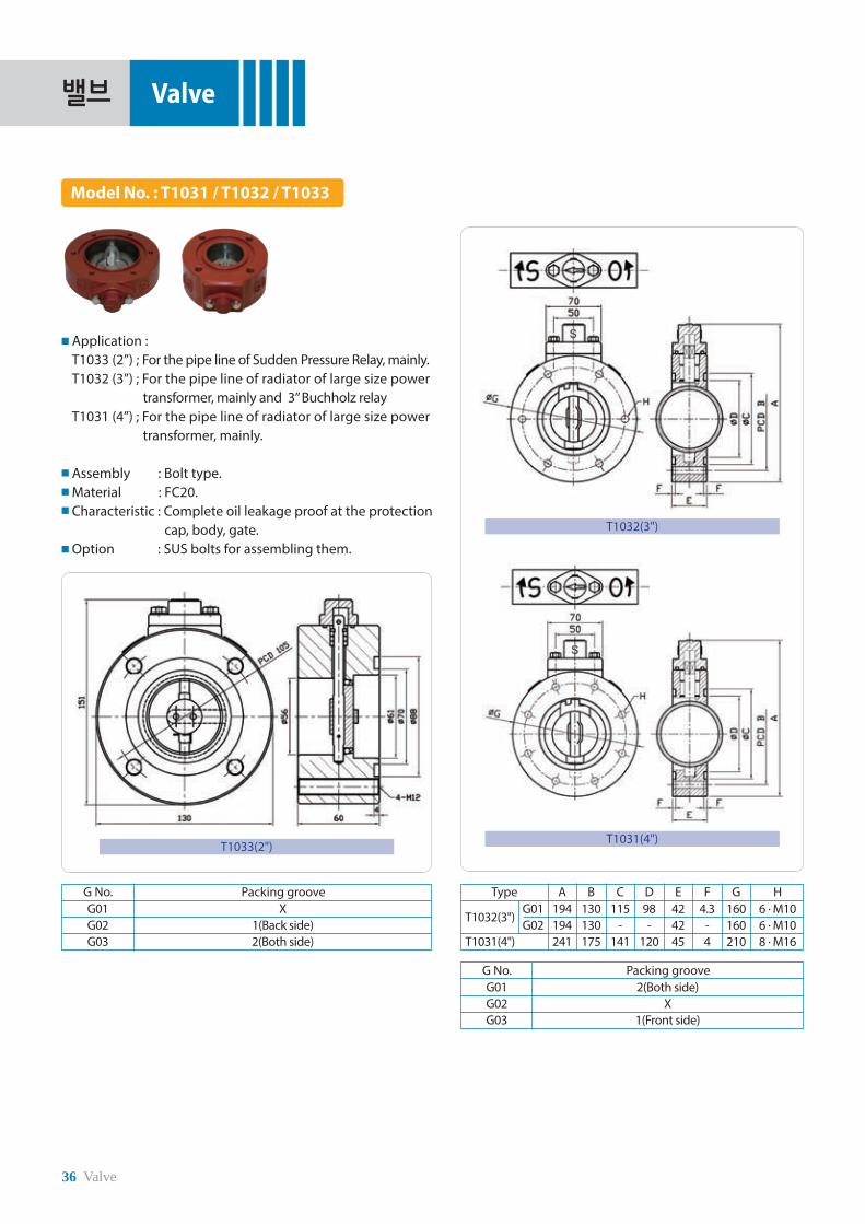
Model No. : T1031 / T1032 / T1033
Application : T1033 (2”) ; For the pipe line of Sudden Pressure Relay, mainly. T1032 (3”) ; For the pipe line of radiator of large size power transformer, mainly and 3” Buchholz relay T1031 (4”) ; For the pipe line of radiator of large size power transformer, mainly. Assembly : Bolt type.Material : FC20.Characteristic : Complete oil leakage proof at the protection cap, body, gate.Option : SUS bolts for assembling them.
Type A B C D E F G H
T1032(3")
T1031(4")
G01G02
194194241
130130175
115-
141
98-
120
424245
4.3-4
160160210
6 . M106 . M108 . M16
G No. Packing grooveG01G02G03
X1(Back side)2(Both side)
T1033(2")
T1032(3")
T1031(4")
G No. Packing grooveG01G02G03
2(Both side)X
1(Front side)

PreservationLevel
FlowPressure
ProtuctCooling
ValveTem
peratureTerm
inal
Valve 37
밸브 Valve
Model No. : T1201 / T1205 Model No. : T1204
Application : For sampling and draining oil. Assembly : Screw type.Material : BS.Type : T1201 (Ø4) for small T1205 (Ø8) for large
Application : Oil inlet cap. Assembly : Screw type.Material : ALDC.Type : T1204.
1. Cover(Bs)2. Body(Bs)3. O-Ring(NBR)
1. Cover(AL) 2. Bolt(Bs) 3. Body(Bs) 4. Boss(SS400)
4. Boss(SS400)5. Rubber Hanger(EDPM)
Sampling valve Oil inlet cap
1. Oil inlet cap 2. 2" pipe 3. Packing
Model (Unit : mm)
Item ØA B C ØDT1201T1205
BodyBody
48
1010
5369
2628

Temperature Indicator
Product Group : T11
Thermometer is an apparatus to measure the oil temperature of transformer and the winding temperature of mold type transformer. The thermometer is mostly waterproof, shockproof, dial type and indicates transformer temperature as a state of assembling the relay on transformer. The thermometer is classified into bimetal type or bourdon tube pressure gauge type in accordance with the assembly position or service of the thermometer on transformer and has an alarm contact and a trip contact to protect the transformer from a fault. The thermometer can be used for outdoor in the temperate regions as well as tropical regions because the thermometer is made of anticorrosive material.
Thermometer body is made from aluminum alloy and has a tempered glass on thermometer face to check the needle indication of thermometer. Some of weatherproof thermometer bodies have a ventilation hole at the bottom of the thermometer.
We have various thermometers in size as well as in shape for pole transformers. Our thermometers have a good reputation in the world market because the thermometers have a solid construction and a graceful shape as well.
온도계(Thermometer)는 유입식 또는 몰드변압기의 절연유 온도 및 권선의 온도를 측정하는 계기입니다. 이 온도계는 주로 방수 내충격형의 다이알형 계
기로서 변압기 탱크 외벽에 부착되어 온도를 지시하며, 그 취부하는 장소와 용도에 따라 바이메탈식과 부르동관식이 있고 변압기 보호를 위한 경보 . 차단
접점을 구비하고 있는 것도 있습니다. 또한 이 온도계는 온대지방 뿐만 아니라 열대지방에서도 옥외용으로 사용할 수 있도록 방청재로 만들어져 있습니다.
외함은 주로 알루미늄 합금으로 되어있고 견고한 투명창이 있습니다. 이 외함은 내후성으로 되어 있고, 종류에 따라 하부에 환기구멍이 구비되어 있는
제품도 있습니다.
태진공업(주)의 온도계는 부착되는 변압기의 종류와 특성에 따라 그 크기와 모양이 다양하여 주상변압기 및 소형변압기에 사용할 수 있도록 다양한 제품
군을 보유하고 있으므로 폭넓은 선택의 범위를 제공하고 있을 뿐 아니라 견고한 구조와 미려한 외관으로 국내 . 외에서 그 제품의 우수성을 인정받고
있습니다.
T1101 T1102 T1103 / T1104 / T1105 T1106
Product Table
Model No. Specification T1101T1102AT1102BT1102HT1103T1104T1105T1106AT1106BT1106CT1106DT1106E
Ø75, BimetalØ75, Bimetal (Max. indicator)Ø75, BimetalØ75, BimetalØ128, Bimetal - 1 ContactØ128, Bimetal - 2 ContactsØ128, Bimetal - 2 ContactsØ96, Bourdon - 1 ContactØ96, Bourdon - 2 ContactsØ96, Bourdon - 2 ContactsØ96, Bourdon - 1 ContactØ96, Bourdon - 2 Contacts
With pocketWith pocket (Ø14)With pocket (Ø10)With pocket (Ø14)75º, 85º With pocket75º, 95º With pocket95º, 115º Without pocketC/L - 2000 mmC/L - 2000 mmC/L - 3000 mmC/L - 2000 mm ~ 5000 mmC/L - 2000 mm, 5000 mm

PreservationLevel
FlowPressure
ProtuctCooling
ValveTem
peratureTerm
inal
Temperature Indicator 39
온도계 Temperature Indicator
Model No. : T1101 Model No. : T1102
Application : For measuring the oil temperature of small oil immersed transformers.Assembly : Fitting thermometer sensor in a protective pocket assembled on the transformer tank cover.Construction : Bimetal.Type : T1101.
1. Thermometer2. Protection tube
3. Half coupling4. Tank wall
5. Sensor1. Body 2. Inspection glass 3. Nut 4. Sensor 5. Pocket
Model and specification.Model
T1101
Item H01H02H03
B185255215
L170240200
취부방식
PT1/2PT1/2PT1/2
(unit : mm)
Characteristic. The waterproof and shockproof type thermometers for small transformer indicates oil temperature as a dial type instrument assembled on transformer tank cover or side wall. The thermometer is directry connected a needle to bimetal and the body is separated from protective pocket.Transformer tank is perfectly separated from the sensor because the sensor is fitted in a protective pocket assembled on transformer tank. The temperature indication range is 0 ~ 120 ºC.
주요특징
본 소형 유입식 변압기용 온도계는 방수 내충격형의 다이알형 계기로서 탱크 카바 또는 벽면에 부착되어 유면의 온도를 지시합니다. 이 온도계는 지침의 바이메
탈을 직접 연결한 것으로 본체와 보호관으로 분리되며, 먼저 보호관을 카바에 부착시킨 후 본체의 감온부는 보호관에 삽입 부착시키며 변압기는 보호관에 의해
완전 밀봉됩니다. 온도범위는 0~120℃ 입니다.
Model and specification.
Model
BimetalBimetalBimetal
T1102AT1102BT1102H
Type
OXX
Max. indic.
O (Ø14)O (Ø10)O (Ø14)
807580
Sensor
757575
¢
(unit : mm)
PT 1/ 2PT 3/8PT 1/ 2
Assembly
* Temperature indication range - A, B, H : 0~120°
Application : For measuring the oil temperature of small oil immersed transformers.Assembly : Fitting thermometer sensor in a protective pocket assembled to the transformer tank side wall.Construction : Bimetal.Type : T1102A, T1102B, T1102H

40 Temperature Indicator
온도계 Temperature Indicator
Model No. : T1103 / T1104 / T1105 Model No. : T1106
Application : For measuring the temperature of dry, mold type transformers.Assembly : The thermometor install the transformer side wall or into junetion box after fitting the sensor at the top of the transformer inside.Construction : Bourdon tube pressure gauge type , Contact. Type : T1106A ~ / T1106E.
Model and specification.
Model and specification.
ModelT1103T1104T1105 Model
T1106AT1106BT1106CT1106DT1106E
Ø128128128 Type
F2AF1BHD1C2C
PocketOOX Ø
9696969696
ApplicationOilOil
Winding Cont12212
Cont.122 Tube (m)
223
2 to 52/5
SettingH01-75ºC, H02-85ºC
75ºC, 95ºC.95ºC, 115ºC. Assembly
Pad bracketPad bracket
PT 1/ 2 screwPT 1/ 2 screwPT 1/ 2 screw
(Unit ; mm)
(Unit ; mm)
Option ; Temp. range / Cable length (more than 1.2 m) / Operation Temp. / Pocket length.Temp. range ; 0 ~ 120ºC.Contact connection diagram.
Option ; Temp. range / Tube / No. of contact / Temp. setting (adjustable from outside). Temp. range ; 0 ~ 200ºC (T1106 A / B / C). 0 ~ 150ºC (T1106 D / E).
Micro Switch CapacityVoltage Resistance Load(Amps) Inductive Load(Amps)125AC250AC125DC250DC
55
0.50.25
33
0.050.025
Application : For measuring the oil temperature of oil immersed small transformers.Assembly : Fitting thermometer sensor in a protective pocket assembled to the transformer tank side wall.Construction : Bimetal, Contact, Maximum indicator.Type : T1103 / T1104 / T1105.
T1103 / T1104
T1105

Cooling Fan
T2106, 2143 T2127, 2128, 2129,2136, 2137, 2141,
2148, 2164, 2167, 2168
T2151, 2166
Product Group : T21
Cooling fan is an apparatus used for cooling down the insulation oil heated by the losses of transformer with the cooling systems of forced air cooling, forced oil cooling.
Cooling fans are characteristic of high efficient, lower sound level. The fans blow air among radiator pins as a state of attaching on the radiator and are solidly manufactured to use them outdoor during long period.Especially fan blades to supply radiator with much air are made from anticorrosive aluminum and net shape fan guide is made of a thick wire and also the guide takes consideration into operator’s safety and air flow resistance.In case F class fan motors are character of waterproof, total abolition as a perfect sealing construction, therefore the motor efficiency does not deteriorate even though the motors are in service during long period.
Various cooling fans to meet many kinds of specifications and standards to satisfy customer’s requirements such as high efficiency, lower noise level, a solid construction as well as a graceful shape , therefore cooling fans have a good reputation in the world market.
쿨링팬(Cooling Fan)은 풍냉식 냉각방식(OFAF, FA) 및 방열기를 채용한 송유풍냉식(FOA) 냉각방식의 변압기의 절연유 냉각에 사용되는 장치입니다.
태진공업(주)의 쿨링팬은 높은 효율과 저소음의 냉각장치로서 주로 방열기(Radiator)에 부착되어 방열관 사이로 공기를 강제 순환시키며 옥외에서 장기간
사용이 가능하도록 견고하게 제작되었습니다. 특히 다량의 풍량을 공급하는 회전날개는 녹이 슬지 않는 알루미늄으로 제작되어 있고 굵은 철선의 망상
구조로 된 팬가드는 안전운전과 공기저항을 최소화하고 있습니다. 또한 완전 밀폐형 구조로서 F종 절연의 방수전폐형 구동모터는 장기간의 사용에도 성
능이 저하되지 않는 구조입니다. 본 쿨링팬은 변압기의 냉각을 위해 필요에 따라 다양한 규격과 사양의 제품이 구비되어 있으며 고효율 . 저소음 . 고신
뢰성 및 견고한 구조와 미려한 외관으로 국내 . 외에서 그 제품의 우수성을 인정받고 있습니다.

42 Cooling Fan
쿨링팬 (송풍기) Cooling Fan
1. Noise test was measured at four direction (east, west, south and north) of cooling fan sides on height 1m and distans 1.83m 16') and we took average value of the results.
2. Air volume measurement method : KS B 6311.
3. T2164Y, T2166Y, T2167Y, T2167Z, T2168Y and T2168Z were certitieated by C.E standard.
1. 소음 : 1.83m(6')에서 동서남북 평균
2. 풍량 : 시험 조건은 KS B 6311 '피토우관과 정류망 (금속제)을 사용한 경우'에 따른다.
Volt.PH HZ
1 603 50ABCDEFGHIJKLMNOPQRSTUVWXYZ
220/380440460480120120208220380415460440208240120220400240230208230575600400
230/400220/380
VVV
VV
VVVVVVVVVVVV V
VVV
VVVVV
VVVVV
VVVV
VVVVVVVVV
VVVVV V V
V
VV
Pole Hz RPM m3/sec
1PH:1/33PH:1/2
55
1PH:1/33PH:1/2
MODEL
T2106A~Z
T2127A~Z
T2128A~Z
T2129A~Z
T2136A~Z
T2137A~Z
T2141A~Z
T2143A~Z
T2148A~Z
T2151A~Z
T2164A~Z
T2166A~Z
T2167A~Z
T2168A~Z
8
6
8
6
6
6
8
8
6
8
6
8
6
8
26
23
23
23
23
23
23
21
23
24
23
24
23
23
1/3
1/8
1PH:1/33PH:1/2
1PH:1/33PH:1/2
1/8
1PH:1/33PH:1/2
470X584
584X584
470X584
584X584
470X584
584X584
470X584
470X584
584X584
584X584
584X584
584X584
470X584
470X584
dBA
F
F
F
F
F
F
F
F
F
F
F
F
F
F
60506050605060506050605060506050605060506050605060506050
840700
1150960840700
1150960
1150960
1150960840700820700
1150960820690
1150960820710
1150960840700
2.72.23.72.92.52.03.72.93.32.73.72.92.52.02.72.23.72.92.52.23.72.92.52.23.32.72.52.0
59566357565363576257635756535855635750476357504762565451
Ins. kg HP IPL X W (mm)

PreservationLevel
FlowPressure
ProtuctCooling
ValveTem
peratureTerm
inal
Cooling Fan 43
쿨링팬 (송풍기) Cooling Fan
Model No. : T2106, 2143
Model No. : T2127, 28, 29, 36, 37, 48, 64, 67, 68, 41
Model No. : T2151

44 Cooling Fan
쿨링팬 (송풍기) Cooling Fan
Characteristic. Cooling fan consists of two pieces of fan guards, a fan motor, four blades.
1. Fan guard. The fan guard made of a thick wire takes the shape of circle and consists of motor support and blade protection net.Since the guard perfectly protects the blade from damage and minimize flow resistance, cooling fan can be operated on lower noise and high efficiency. 2. Motor. Since the motor is characteristic of waterproof, total abolition as a perfect sealing construction as well as F class insulation class, the motor can be operated on high efficiency even though the motors are in outdoor service during long period.3. Blade. The blade is designed to provide sufficient airflow, efficiently. Since the blade is made of aluminum plate or made from aluminum die casting, it is light, anticorrosive and also can withstand high temperature. Therefore, the blade can be operated under various ambient conditions including tropical climates. Especially, the blade exactly balanced by machine has characteristic to minimize it’s noise level. 4. The surface treatment of fan guard. The guard is hot-dipped galvanized, and is coated by wash primer and final paint (5Y 7/1).
구조
본 쿨링팬은 팬가드(Fan Guard), 구동모터 및 회전날개(Blade)로 구성되어
있습니다.
1. 팬가드
굵은 철선으로 동심원을 이룬 형태로 이루고 있으며 구동모터 취부대와
팬보호망으로 구성됩니다.
안전하게 운전되고 바람에 대한 저항을 최소화하여 저소음 . 고효율로 운
전할 수 있습니다.
2.구동모터
방수 . 전폐형으로, 'F'종 절연을 하였으므로 장시간의 연속사용에도 고효
율을 유지합니다.
3.회전날개
다량의 풍량을 효과적으로 공급할 수 있도록 설계 되었고 알루미늄판
(Propeller) 또는 알루미늄 다이케스팅(Axial)으로 제작되어 가볍고 내부식
성이 강하며 고온에도 잘 견디므로 전천후 운전이 가능합니다. 특히 밸런
싱 머신으로 정확히 균형이 잡힌 상태에서 부착되므로 소음을 최소화할
수 있는 특징이 있습니다.
4.팬가드 표면처리
용융아연도금+Wash Primer+Final Panting(5Y 7/1)
A EB ØF Blade Type NotesØC(Blade)
T2106
T2127
T2128
T2129
T2136
T2137
T2141
T2143
T2148
T2151
T2164
T2166
T2167
T2168
470
584
470
584
470
584
470
470
584
584
584
584
470
470
400
373
373
373
373
373
373
384
373
360
373
360
373
373
584
584
584
584
584
584
584
584
584
584
584
584
584
584
788
864
788
864
788
864
788
788
864
864
864
864
788
788
610
665
615
665
615
665
615
610
665
675
665
675
615
615
12.5
12.5
12.5
12.5
12.5
12.5
12.5
12.5
12.5
12.5
12.5
12.5
12.5
12.5
PITCH D(Fan guard)
Propeller(4EA) Standard, Motor(90Fr.)
T2136+T.P+C.E(Y, Z)
T2128+C.E(Y.Z)
T2127+blade(Hard coat anodized)+motor shaft(sus410)+T.P+C.E(Y)Axial(4EA)
Axial(4EA)
T2128+plug type connectorAxial(4EA)
T2137+plug type connectorAxial(4EA)
Low NoisePropeller(4EA)
T2127+blade(Hard coat anodized)+motor shaft(sus410)+T.P+C.E(Y)
Propeller(4EA)
Propeller(4EA) Standard Motor(80Fr.)
Standard, High efficiency
Noise +Air volume +TP(Thermal Protection)
T2127+Blade(Hard coat anodized)+Motor Shaft(SUS410)+Service Factor(1.15)
T2127 Noise +Air volume
T2127+TP(Thermal Protection)
Axial(4EA)
Option ; Input Voltage (AC, V), Phase, frequency(50Hz/60Hz), Horse power, Poles, Insulation class (B/F), T.P (Thermal Protection), Motor shaft material, Noise, Air volume and Service factor etc.

BCT Terminal Box
T9001 / T9015
Product Group ; T90
Bushing Current Transformer Terminal Box is an apparatus for connecting the secondary leads of Bushing Current Transformer of oil immersed transformer to the terminal block fitted in local control panel.
The terminal box is usually attached on a nearby position of the transformer cover or bushing housing and has a solid construction and an airtight construction as well.
The terminal boxes are classified into 4 terminal, 6 terminal, or 12 terminal box according to terminal number of the box.The terminal box has a solid, good electrical construction and good thermal characteristic.Therefore, the box is supplying to well known transformer manufacturers in the world market and the excellencies of the box is recognized by all the manufacturers in the would market.
BCT 단자함(BTB, BCT Terminal Box)은 유입식 변압기의 붓싱변류기(BCT) 각단자 Cable을 현지제어반으로 연결시켜 주기 위한 인입 . 인출 단자연결함
으로 사용되는 장치입니다.
단자함은 붓싱에 인접한 탱크 카바나 챔버에 부착되며, 구조가 견고하고 완전 밀봉되어야 합니다.
태진공업(주)의 BCT 단자함은 BCT 단자의 수량에 따라「4단자」,「6단자」및
「12단자」를 구비하고 있고, Compact하고 견고한 구조와 양호한 전기적 . 열적인 특성으로 인해 국내 . 외 유수한 업체에 공급되며 그 제품의 우수성을
인정받고 있습니다.
Product Table
Model No. ApplicationT9001T9015
Medium, large transformerMedium, large transformer
Characteristic.Bushing Current Transformer (BCT) terminal box is an apparatus for oil immersed transformers and is characteristic of electrical, thermal ability as well as sealing capability proven through the tests of an authorized institute.
1. Airtight test ; proven under test pressure of 2 kg / cm² by air.
2. Power frequency withstand voltage test. ; Test voltage of 2.5 KV is applied to among terminals as well as between each terminal and box flange for 1 minute.
주요특징
본 유입식 변압기용 BCT 단자함은 초고압변압기용 부품으로서 구비해야 할 각종 전기적·열적인 성능 및 기밀(유밀)성능은 시험을 통해 검증된 제품입니다.
1. 기밀시험 : 2kg/cm²의 공기압으로 시험한다.
2. 내압시험 : 각 단자간과 플랜지간에 2.5kV전압을 1분 인가
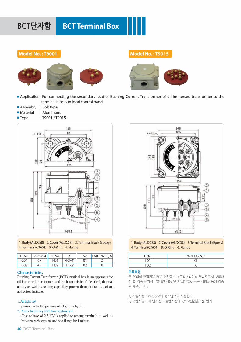
BCT단자함
46 BCT Terminal Box
BCT Terminal Box
Model No. : T9001 Model No. : T9015
Application : For connecting the secondary lead of Bushing Current Transformer of oil immersed transformer to the terminal blocks in local control panel.
Assembly : Bolt type.Material : Aluminum.Type : T9001 / T9015.
G. No. TerminalG01G02
6P4P
H. No. AH01H02
PF3/4"PF1/2"
I. No. PART No. 5, 6I 01I 02
OX
1. Body (ALDCS8) 2. Cover (ALDCS8) 3. Terminal Block (Epoxy)4. Terminal (C3601) 5. O-Ring 6. Flange
Characteristic. Bushing Current Transformer (BCT) terminal box is an apparatus for oil immersed transformers and is characteristic of electrical, thermal ability as well as sealing capability proven through the tests of an authorized institute.
1. Airtight test ; proven under test pressure of 2 kg / cm² by air.2. Power frequency withstand voltage test. ; Test voltage of 2.5 KV is applied to among terminals as well as
between each terminal and box flange for 1 minute.
주요특징
본 유입식 변압기용 BCT 단자함은 초고압변압기용 부품으로서 구비해
야 할 각종 전기적 . 열적인 성능 및 기밀(유밀)성능은 시험을 통해 검증
된 제품입니다.
1. 기밀시험 : 2kg/cm²의 공기압으로 시험한다.
2. 내압시험 : 각 단자간과 플랜지간에 2.5kV전압을 1분 인가
I. No. PART No. 5, 6I 01I 02
OX
1. Body (ALDCS8) 2. Cover (ALDCS8) 3. Terminal Block (Epoxy)4. Terminal (C3601) 5. O-Ring 6. Flange
![[(SPAN)- ] - BONGSHIN · 2015. 11. 16. · [(SPAN)- ]스판 조정 실부하입력 예 최대표시눈금) :100.00kg 한눈의값 최소표시눈금()10g 표준분동 이준비되었을때50.00kg](https://static.fdocuments.net/doc/165x107/602a8a870aadc84d86728be0/span-2015-11-16-span-oe-ee-oeeoeoeoeee.jpg)


![All the Ä PUNZ · Beginner s Guide Robin Pritchard Join CNF Store Manager, Robin Pritchard, as she shares simple dehydrating [PWZ -\UHUKJVZ[ LHLJ[P]L dehydrating is an easy way to](https://static.fdocuments.net/doc/165x107/5f66bee51de22533520175c4/all-the-punz-beginner-s-guide-robin-pritchard-join-cnf-store-manager-robin-pritchard.jpg)


