Compactor Wacker Plate - Lumag Distribution Ltd · Compactor Wacker Plate Operator’s Manual...
24
Distribution Limited Compactor Wacker Plate Operator’s Manual RPi31DE FOR YOUR SAFETY READ AND UNDERSTAND THE ENTIRE MANUAL BEFORE OPERATING THIS MACHINE
Transcript of Compactor Wacker Plate - Lumag Distribution Ltd · Compactor Wacker Plate Operator’s Manual...

Distribution Limited
Compactor Wacker PlateOperator’s Manual
RPi31DE
FOR YOUR SAFETYREAD AND UNDERSTAND THE ENTIRE MANUAL
BEFORE OPERATING THIS MACHINE


Warranty Registration Form
For the warranty to be valid the Warranty Registration Form must be completed and returned to Lumag Distribution Limited within 14 days of the purchase, together with a copy of the purchase invoice.
We will use your email to confirm that we have received the completed Warranty Registration Form and contact you about any errors or omissions on the form. We may occasionally use this email address to make you aware of news, technical advice and special offers. If you do not wish to receive such emails please tick this box.
Unit 10, Hatchmoor Industrial Estate, Hatherleigh, Okehampton, Devon EX20 3LPwww.lumag-gb.co.uk 01837 811741
Lumag Distribution Limited Company Number: 09267547 VAT Number: GB154566788 Hatherleigh Plant and Tool Hire is a trading name of Lumag Distribution LTD
Model:Serial Number:Type of Use: Business / DomesticName:Business Name:Address:Email Address:Phone Number:Date of Purchase:Place of Purchase:Proof of Purchase enclosed:
Distribution Limited

Distribution Limited
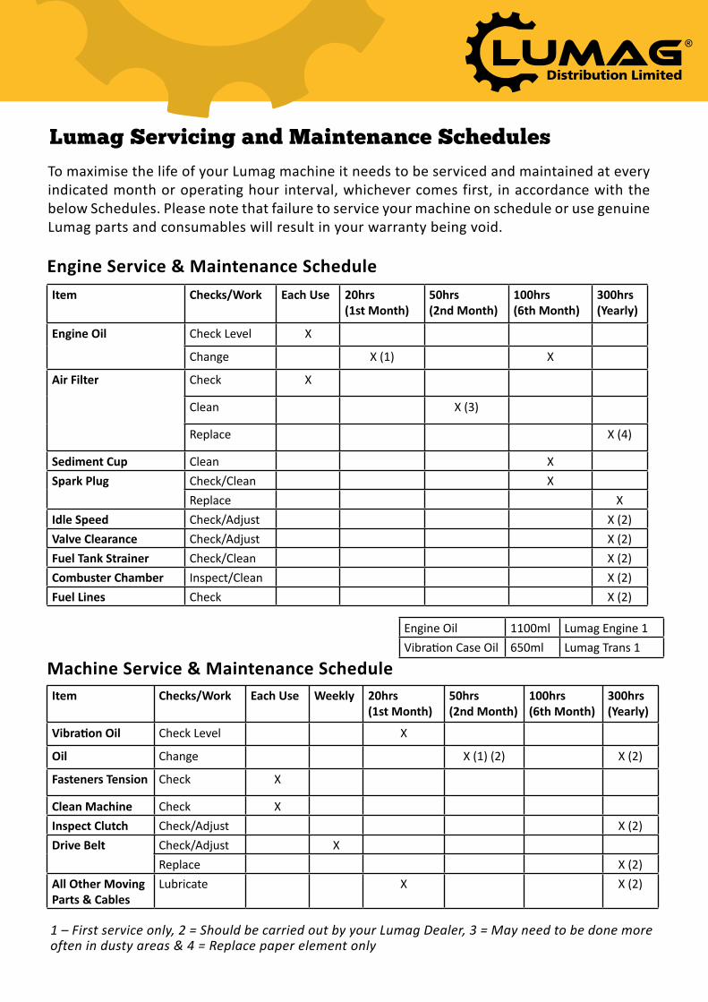
Lumag Servicing and Maintenance Schedules
Engine Service & Maintenance Schedule
Machine Service & Maintenance Schedule
Item Checks/Work Each Use 20hrs (1st Month)
50hrs (2nd Month)
100hrs (6th Month)
300hrs (Yearly)
Engine Oil Check Level X
Change X (1) X
Air Filter Check X
Clean X (3)
Replace X (4)
Sediment Cup Clean XSpark Plug Check/Clean X
Replace XIdle Speed Check/Adjust X (2)Valve Clearance Check/Adjust X (2)Fuel Tank Strainer Check/Clean X (2)Combuster Chamber Inspect/Clean X (2)Fuel Lines Check X (2)
Item Checks/Work Each Use Weekly 20hrs (1st Month)
50hrs (2nd Month)
100hrs (6th Month)
300hrs (Yearly)
Vibration Oil Check Level X
Oil Change X (1) (2) X (2)
Fasteners Tension Check X
Clean Machine Check XInspect Clutch Check/Adjust X (2)Drive Belt Check/Adjust X
Replace X (2)All Other Moving Parts & Cables
Lubricate X X (2)
Engine Oil 1100ml Lumag Engine 1Vibration Case Oil 650ml Lumag Trans 1
1 – First service only, 2 = Should be carried out by your Lumag Dealer, 3 = May need to be done more often in dusty areas & 4 = Replace paper element only
To maximise the life of your Lumag machine it needs to be serviced and maintained at every indicated month or operating hour interval, whichever comes first, in accordance with the below Schedules. Please note that failure to service your machine on schedule or use genuine Lumag parts and consumables will result in your warranty being void.

Dis
trib
uti
on
Lim
ited
Ser
vic
e &
Ma
inte
na
nce
Rec
ord
Prod
uct D
etai
ls:
Mod
el: _
____
____
____
____
____
____
____
____
_
Seria
l num
ber:
___
____
____
____
____
____
____
_Pu
rcha
se D
ate:
___
____
____
____
____
____
____
_
Date
:D
escr
iptio
n of
che
cks/
wor
k ca
rrie
d ou
t:Pa
rts U
sed?
Y/
NPa
rts I
nvoi
ce
Num
ber:
Deal
ers
Nam
e:En
gine
ers
Nam
e:En
gine
ers
Sign
atur
e:
Plea
se n
ote
that
failu
re to
ser
vice
you
r mac
hine
on
sche
dule
or u
se g
enui
ne
Lum
ag p
arts
and
con
sum
able
s w
ill re
sult
in y
our w
arra
nty
bein
g vo
id
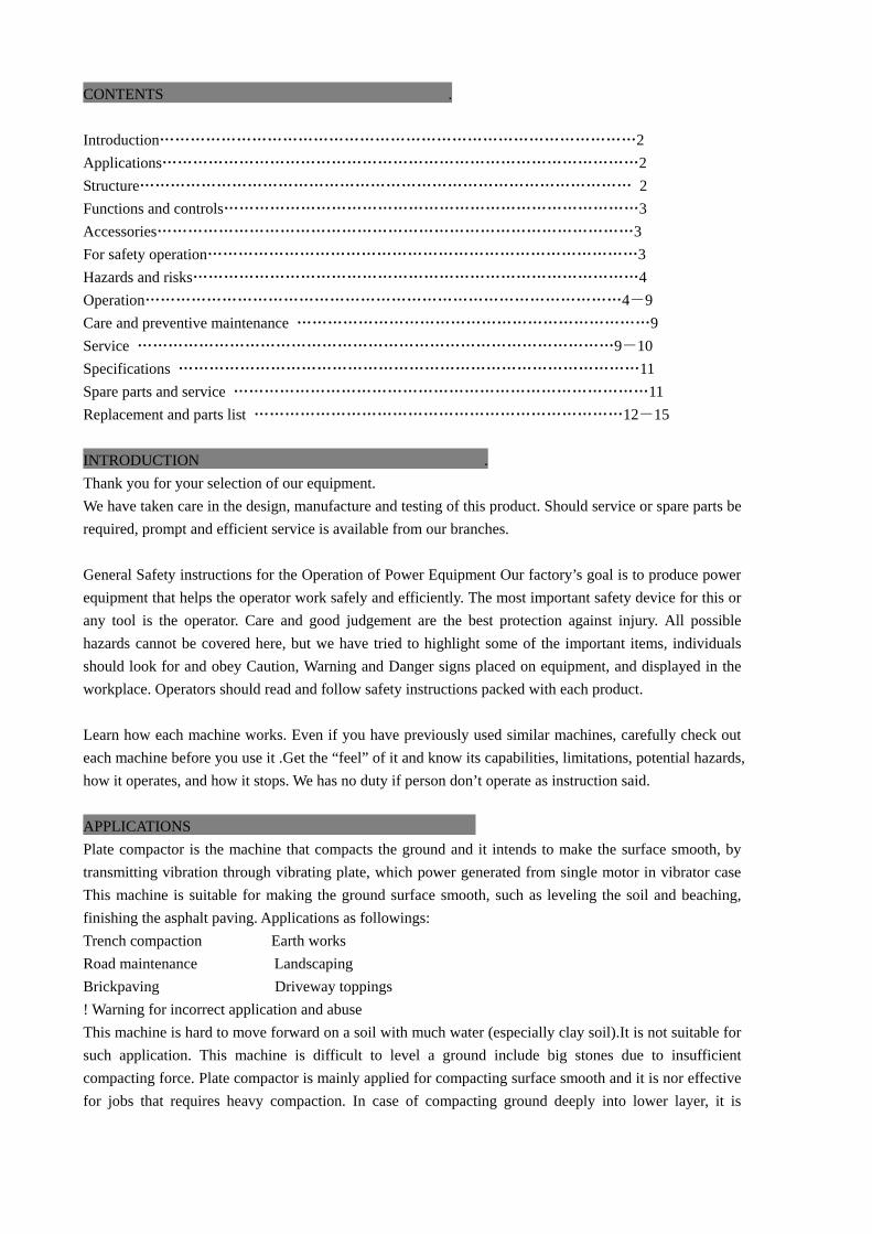
CONTENTS . Introduction⋯⋯⋯⋯⋯⋯⋯⋯⋯⋯⋯⋯⋯⋯⋯⋯⋯⋯⋯⋯⋯⋯⋯⋯⋯⋯⋯⋯⋯⋯⋯2 Applications⋯⋯⋯⋯⋯⋯⋯⋯⋯⋯⋯⋯⋯⋯⋯⋯⋯⋯⋯⋯⋯⋯⋯⋯⋯⋯⋯⋯⋯⋯⋯2 Structure⋯⋯⋯⋯⋯⋯⋯⋯⋯⋯⋯⋯⋯⋯⋯⋯⋯⋯⋯⋯⋯⋯⋯⋯⋯⋯⋯⋯⋯⋯⋯⋯ 2 Functions and controls⋯⋯⋯⋯⋯⋯⋯⋯⋯⋯⋯⋯⋯⋯⋯⋯⋯⋯⋯⋯⋯⋯⋯⋯⋯⋯⋯3 Accessories⋯⋯⋯⋯⋯⋯⋯⋯⋯⋯⋯⋯⋯⋯⋯⋯⋯⋯⋯⋯⋯⋯⋯⋯⋯⋯⋯⋯⋯⋯⋯3 For safety operation⋯⋯⋯⋯⋯⋯⋯⋯⋯⋯⋯⋯⋯⋯⋯⋯⋯⋯⋯⋯⋯⋯⋯⋯⋯⋯⋯⋯3 Hazards and risks⋯⋯⋯⋯⋯⋯⋯⋯⋯⋯⋯⋯⋯⋯⋯⋯⋯⋯⋯⋯⋯⋯⋯⋯⋯⋯⋯⋯⋯4 Operation⋯⋯⋯⋯⋯⋯⋯⋯⋯⋯⋯⋯⋯⋯⋯⋯⋯⋯⋯⋯⋯⋯⋯⋯⋯⋯⋯⋯⋯⋯⋯4-9 Care and preventive maintenance ⋯⋯⋯⋯⋯⋯⋯⋯⋯⋯⋯⋯⋯⋯⋯⋯⋯⋯⋯⋯⋯⋯⋯9 Service ⋯⋯⋯⋯⋯⋯⋯⋯⋯⋯⋯⋯⋯⋯⋯⋯⋯⋯⋯⋯⋯⋯⋯⋯⋯⋯⋯⋯⋯⋯⋯9-10 Specifications ⋯⋯⋯⋯⋯⋯⋯⋯⋯⋯⋯⋯⋯⋯⋯⋯⋯⋯⋯⋯⋯⋯⋯⋯⋯⋯⋯⋯⋯⋯11 Spare parts and service ⋯⋯⋯⋯⋯⋯⋯⋯⋯⋯⋯⋯⋯⋯⋯⋯⋯⋯⋯⋯⋯⋯⋯⋯⋯⋯⋯11 Replacement and parts list ⋯⋯⋯⋯⋯⋯⋯⋯⋯⋯⋯⋯⋯⋯⋯⋯⋯⋯⋯⋯⋯⋯⋯⋯12-15 INTRODUCTION . Thank you for your selection of our equipment. We have taken care in the design, manufacture and testing of this product. Should service or spare parts be required, prompt and efficient service is available from our branches. General Safety instructions for the Operation of Power Equipment Our factory’s goal is to produce power equipment that helps the operator work safely and efficiently. The most important safety device for this or any tool is the operator. Care and good judgement are the best protection against injury. All possible hazards cannot be covered here, but we have tried to highlight some of the important items, individuals should look for and obey Caution, Warning and Danger signs placed on equipment, and displayed in the workplace. Operators should read and follow safety instructions packed with each product. Learn how each machine works. Even if you have previously used similar machines, carefully check out each machine before you use it .Get the “feel” of it and know its capabilities, limitations, potential hazards, how it operates, and how it stops. We has no duty if person don’t operate as instruction said. APPLICATIONS Plate compactor is the machine that compacts the ground and it intends to make the surface smooth, by transmitting vibration through vibrating plate, which power generated from single motor in vibrator case This machine is suitable for making the ground surface smooth, such as leveling the soil and beaching, finishing the asphalt paving. Applications as followings: Trench compaction Earth works Road maintenance Landscaping Brickpaving Driveway toppings ! Warning for incorrect application and abuse This machine is hard to move forward on a soil with much water (especially clay soil).It is not suitable for such application. This machine is difficult to level a ground include big stones due to insufficient compacting force. Plate compactor is mainly applied for compacting surface smooth and it is nor effective for jobs that requires heavy compaction. In case of compacting ground deeply into lower layer, it is

recommended to use. Tamping Rammer, Vibro Compactor and Vibration Roller which compacting force is rather effective.Please use this compactor for compacting surface on soil, sediment, sand , beaching and asphalt. It is not recommended for use this machine for the other applications. STRUCTURE The upper part is made up of Power Source, Handle ,Belt Cover and Guard Hook which are fixed by Engine base. The Engine base is fixed on Vibrating Plate by Shock Absorbing Ruber.The lower part is made up of Vibrating Plate and Vibrator unit that has an Eccentric rotary shaft built in. The power source is transmitted from the centrifugal clutch on engine output shaft to the eccentric rotary shaft via V-belt. Power Transfer Air-cooled Single cylinder Engine is amounted as power source and Centrifugal Clutch is fixed on engine output shaft. Petrol Engine(2 cycle, 4 cycle) and Diesel Gasoline Engine can be mounted as option. Centrifugal Clutch engages by running up the engine and engine is reduced o suitable number for compacting. The rotation of engine is transmitted from V-pulley integrated with Clutch drum to Vibrator pulley through V-belt. Vibrator Pulley rotates Eccentric rotor shaft that is contained in Vibrator case. The generated vibration created from eccentric rotor is transmitted to Compaction with the weight of the machine makes the compaction of the ground possible. FUNCTIONS AND CONTROLS Motor The motor is controlled by an ON/OFF switch or push button which is mounted on the motor below the fuel tank. The motor speed is controlled by a remote throttle lever which is mounted on the machine handle. Honda and Kama motors are fitted with an oil alert device which will stop the motor or prevent starting when the crankcase oil level falls below a safe level Drive belt Tension of the drive belt is adjustable. Loosen the four nuts on the bolts which secure the motor to the baseplate, Adjust the set screws which bear against the motor crankcase to achieve the required belt tension .Ensure that the four nuts and the set screw locknuts are tightened after adjustment. ACCESSORIES Thansport Trolley-facilitates handling. Hooks into the baseplate. Fitted with 200mm rubber tyres. FOR SAFETY OPERATION ! This safety alert symbol identifies important safety messages throughout this manual and on the machine. When you see this symbol, carefully read the message that follows. Your safety is at stake! Foreword: It is important to read this manual carefully so that you will fully understand the operational characteristics and performance of the plate compactor, Proper mainternance procedures will insure long life and top performance of the unit.
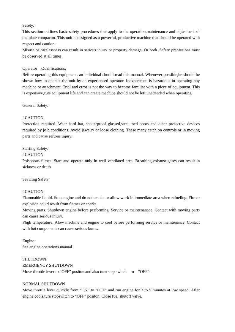
Safety: This section outlines basic safety procedures that apply to the operation,maintenance and adjustment of the plate compactor. This unit is designed as a powerful, productive machine that should be operated with respect and caution. Misuse or carelessness can result in serious injury or property damage. Or both. Safety precautions must be observed at all times. Operator Qualifications: Before operating this equipment, an individual should read this manual. Whenever possible,he should be shown how to operate the unit by an experienced operator. Inexperience is hazardous in operating any machine or attachment. Trial and error is not the way to become familiar with a piece of equipment. This is expensive,cuts equipment life and can create machine should not be left unattended when operating. General Safety: ! CAUTION Protection required. Wear hard hat, shatterproof glassed,steel toed boots and other protective devices required by jo b conditions. Avoid jewelry or loose clothing. These many catch on controls or in moving parts and cause serious injury. Starting Safety: ! CAUTION Poisonous fumes. Start and operate only in well ventilated area. Breathing exhaust gases can result in sickness or death. Sevicing Safety: ! CAUTION Flammable liquid. Stop engine and do not smoke or allow work in immediate area when refueling. Fire or explosion could result from flames or sparks. Moving parts. Shutdown engine before performing. Service or maintenanace. Contact with moving parts can cause serious injury. Fligh temperature. Alow machine and engine to cool before performing service or maintenance. Contact with hot components can cause serious bums. Engine See engine operations manual SHUTDOWN EMERGENCY SHUTDOWN Move throttle lever to “OFF” positon and also turn stop switch to “OFF”. NORMAL SHUTDOWN Move throttle lever quickly from “ON” to “OFF” and run engine for 3 to 5 minutes at low speed. After engine cools,ture stopswitch to “OFF” positon, Close fuel shutoff valve.
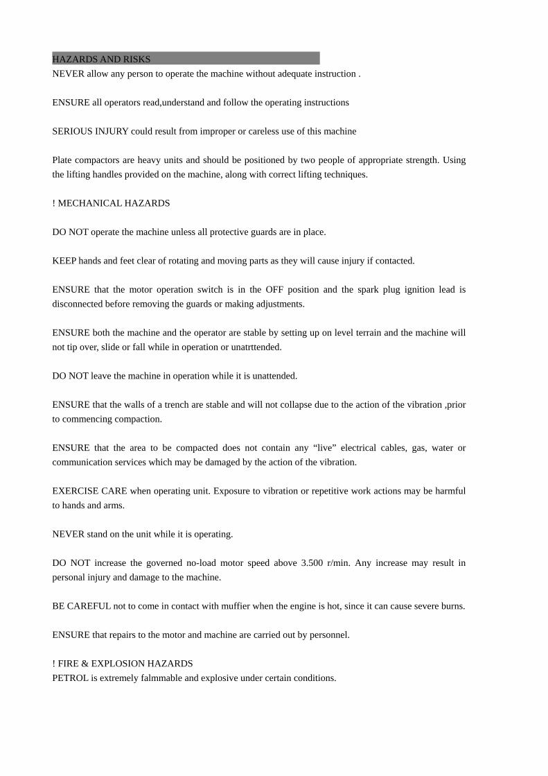
HAZARDS AND RISKS NEVER allow any person to operate the machine without adequate instruction . ENSURE all operators read,understand and follow the operating instructions SERIOUS INJURY could result from improper or careless use of this machine Plate compactors are heavy units and should be positioned by two people of appropriate strength. Using the lifting handles provided on the machine, along with correct lifting techniques. ! MECHANICAL HAZARDS DO NOT operate the machine unless all protective guards are in place. KEEP hands and feet clear of rotating and moving parts as they will cause injury if contacted. ENSURE that the motor operation switch is in the OFF position and the spark plug ignition lead is disconnected before removing the guards or making adjustments. ENSURE both the machine and the operator are stable by setting up on level terrain and the machine will not tip over, slide or fall while in operation or unatrttended. DO NOT leave the machine in operation while it is unattended. ENSURE that the walls of a trench are stable and will not collapse due to the action of the vibration ,prior to commencing compaction. ENSURE that the area to be compacted does not contain any “live” electrical cables, gas, water or communication services which may be damaged by the action of the vibration. EXERCISE CARE when operating unit. Exposure to vibration or repetitive work actions may be harmful to hands and arms. NEVER stand on the unit while it is operating. DO NOT increase the governed no-load motor speed above 3.500 r/min. Any increase may result in personal injury and damage to the machine. BE CAREFUL not to come in contact with muffier when the engine is hot, since it can cause severe burns. ENSURE that repairs to the motor and machine are carried out by personnel. ! FIRE & EXPLOSION HAZARDS PETROL is extremely falmmable and explosive under certain conditions.
ENSURE that petrol is only stored in an approved storage container. DO NOT refuel the motor while it is in operation or hot. DO NOT refuel the motor in the vicinity of sparks, a naked flame or a person smoking. DO NOT over fill the fuel tank and avoid spilling petrol when refueling. Spilled petrol or petrol vapour may ignite. If spillage occurs,ensure that the area is dry before starting the motor. ENSURE theat the fuel tank cap is securely fitted after refueling. ! CHEMICAL HAZARDS DO NOT operate or refuel a petrol or diesel motor in a confined area without adequate ventilation. CARBON MONOXIDE exhaust gases from internal combustion motor driven units can cause death in confined spaces. ! NOISE HAZARDS EXCESSIVE NOISE can lead to temporary or permanent loss of hearing. WEAR an approved hearing protection device to limit noise exposure. As required by Occupational Health and Safety regulations. WEAR an approved hearing protection device to limit noise exposure. As requrede by Occupational Health and Safety regulations. PROTECTIVE CLOTHING ALWAYS wear approved hearing protection when working in a confined work space. Protective goggles and a dust mask should be worn when working in a dusty environment. Protective clothing and footwear may also be desirable wheh working with hot mix bitumen. ! ADDITIONAL HAZARDS Slip/Trip/Fall is a major cause of serious injury or death. Beware of uneven or slippery work surfaces. Exercise care when working in the vicinity of unprotected holes or excavations. OPERATION GENERAL OPERATION The machine is best suited to the compaction of bituminous and granular materials e.g. granular soils,gravels and sands or mixtures of both, Cohesive soils such as silt and clay are best compacted using the impact force produced by a vibrating rammer.
Where possible the site should tbe graded and leveled before commencing compaction. Correct moistrure content in soil is vital to proper compaction.Water acts as a lubricant to help slide soil particles together. Too little moisture means inadequate compaction; too much moisture leaves water-filled voids that weaken the soil's load bearing abiliy. Use unleaded grade petrol and ensure that the fuel is free from contamination. The vibratory motion provides a self propelling action. Position the handle at the opposite end of the machine to the vibrator. Start the motor using the recoil starter. ( If the motor is fitted with and on/off switch this must first be turned to ON before starting. ) For more information of starting and correct operating procedures of the motor, refer to the motor operation manual supplied with the unit. Increase the motor sped to the maximum setting using the hand throttle lever, before commencing compacting. The machine should be controlled by grasping the handle with both hands and applying restraint to control the for ward notion. Forward or backward motion has problem, adjust the red handle or nut s (item 21, 22 in components list) Steer the machine by moving the handle sideways to the right or left. ALWAYS maintain good footing so that you do not slip and loose control when starting or operating the machine. 1. Prior to operation 1-1. Make sure that all dirt, nut, etc., are thoroughly removed from the unit prior to operation. Special
effort should be given to the button face of the vibrating plate and those areas adjacent to the cooling air inlet of engine, carburetor, and air cleaner.
1-2. Check all bolts and screws for tightness and make sure all bolts and screws are securely tightened. Loose bolts and screws may cause damage to the unit.
1-3. Check the V-belt for tightness. The normal slack should be approximately 10-15 mm (1/2’’) when the belts are forcibly depressed in the middle position between the two sheaves. If there is excess belt play. There could be a decrease in the impact force or erratic vibration, causing machine damage.
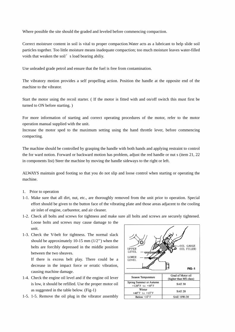
1-4. Check the engine oil level and if the engine oil lever is low, it should be refilled. Use the proper motor oil as suggested in the table below. (Fig-1)
1-5. 1-5. Remove the oil plug in the vibrator assembly
and check the oil level. Make sure the compactor is level when checking. The oil level should be up to the oil plug. Every month or every 200 hours of operation, replace the oil.
! IMPORTIONA Use the motor oil SAE When changing the oil, the old oil can be drained by tipping the unit. The oil will drain easily while it is hot. 1-6. A regular grade gasoline should be used in the engine.
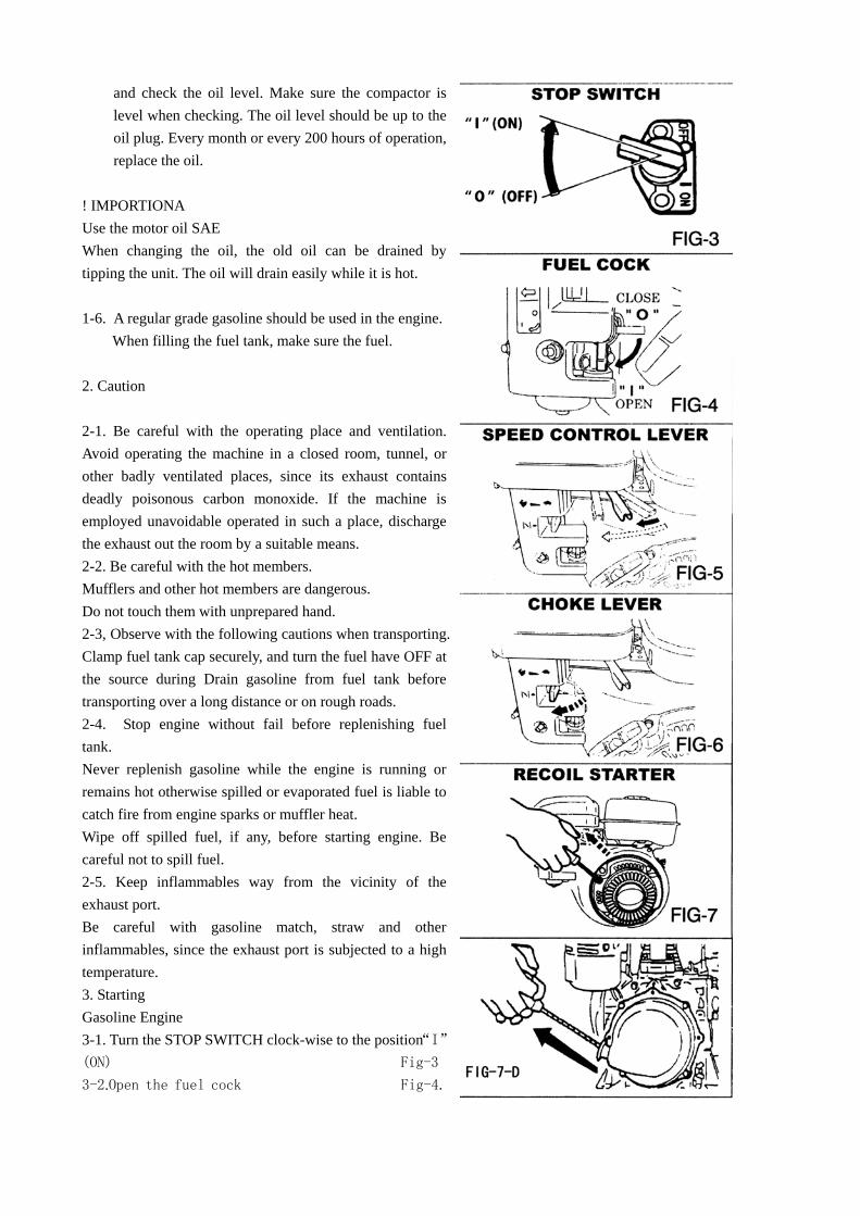
When filling the fuel tank, make sure the fuel. 2. Caution 2-1. Be careful with the operating place and ventilation. Avoid operating the machine in a closed room, tunnel, or other badly ventilated places, since its exhaust contains deadly poisonous carbon monoxide. If the machine is employed unavoidable operated in such a place, discharge the exhaust out the room by a suitable means. 2-2. Be careful with the hot members. Mufflers and other hot members are dangerous. Do not touch them with unprepared hand. 2-3, Observe with the following cautions when transporting. Clamp fuel tank cap securely, and turn the fuel have OFF at the source during Drain gasoline from fuel tank before transporting over a long distance or on rough roads. 2-4. Stop engine without fail before replenishing fuel tank. Never replenish gasoline while the engine is running or remains hot otherwise spilled or evaporated fuel is liable to catch fire from engine sparks or muffler heat. Wipe off spilled fuel, if any, before starting engine. Be careful not to spill fuel. 2-5. Keep inflammables way from the vicinity of the exhaust port. Be careful with gasoline match, straw and other inflammables, since the exhaust port is subjected to a high temperature. 3. Starting Gasoline Engine 3-1. Turn the STOP SWITCH clock-wise to the position“I”(ON) Fig-3
3-2.Open the fuel cock Fig-4.
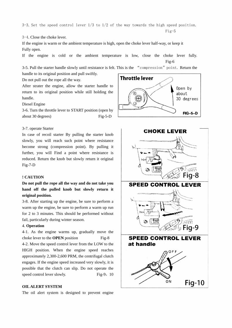
3-3. Set the speed control lever 1/3 to 1/2 of the way towards the high speed position. Fig-5
3-4. Close the choke lever. If the engine is warm or the ambient temperature is high, open the choke lever half-way, or keep it Fully open. If the engine is cold or the ambient temperature is low, close the choke lever fully.
Fig-6 3-5. Pull the starter handle slowly until resistance is felt. This is the “compression”point. Return the handle to its original position and pull swiftly. Do not pull out the rope all the way. After strater the engine, allow the starter handle to return to its original position while still holding the handle. Diesel Engine 3-6. Turn the throttle lever to START position (open by about 30 degrees) Fig-5-D 3-7. operate Starter In case of recoil starter By pulling the starter knob slowly, you will reach such point where resistance become strong (compression point). By pulling it further, you will Find a point where resistance is reduced. Return the knob but slowly return it original Fig-7-D ! CAUTION Do not pull the rope all the way and do not take you hand off the pulled knob but slowly return it original position. 3-8. After starting up the engine, be sure to perform a warm up the engine, be sure to perform a warm up run for 2 to 3 minutes. This should be performed without fail, particularly during winter season. 4. Operation 4-1. As the engine warms up, gradually move the choke lever to the OPEN position Fig-8 4-2. Move the speed control lever from the LOW to the HIGH position. When the engine speed reaches approximately 2,300-2,600 PRM, the centrifugal clutch engages. If the engine speed increased very slowly, it is possible that the clutch can slip. Do not operate the speed control lever slowly. Fig-9,10 OIL ALERT SYSTEM The oil alert system is designed to prevent engine
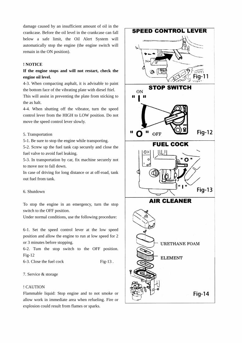
damage caused by an insufficient amount of oil in the crankcase. Before the oil level in the crankcase can fall below a safe limit, the Oil Alert System will automatically stop the engine (the engine switch will remain in the ON position). ! NOTICE If the engine stops and will not restart, check the engine oil level. 4-3. When compacting asphalt, it is advisable to paint the bottom face of the vibrating plate with diesel ftiel. This will assist in preventing the plate from sticking to the as halt. 4-4. When shutting off the vibrator, turn the speed control lever from the HIGH to LOW position. Do not move the speed control lever slowly. 5. Transportation 5-1. Be sure to stop the engine while transporting. 5-2. Screw up the fuel tank cap securely and close the fuel valve to avoid fuel leaking. 5-3. In transportation by car, fix machine securely not to move nor to fall down. In case of driving for long distance or at off-road, tank out fuel from tank. 6. Shutdown To stop the engine in an emergency, turn the stop switch to the OFF position. Under normal conditions, use the following procedure: 6-1. Set the speed control lever at the low speed position and allow the engine to run at low speed for 2 or 3 minutes before stopping. 6-2. Tum the stop switch to the OFF position. Fig-12 6-3. Close the fuel cock Fig-13 . 7. Service & storage ! CAUTION Flammable liquid: Stop engine and to not smoke or allow work in immediate area when refueling. Fire or explosion could result from flames or sparks.
Moving parts: Shutdown engine before performing service or maintenance. Contact with moving parts cause serious injury. High temperature: Allow machine and engine to cool before performing service or maintenance. Contact with hot components can cause serious burn. 7-1. Daily Service A. Remove mud, dirt, ect, from the unit. B. Clean bottom face of the vibrating plate. C. Check the air cleaner element and clean if necessary. D. Check all nuts, bolts, and screws for tightness and retighten as necessary. 7-2. Weekly Service
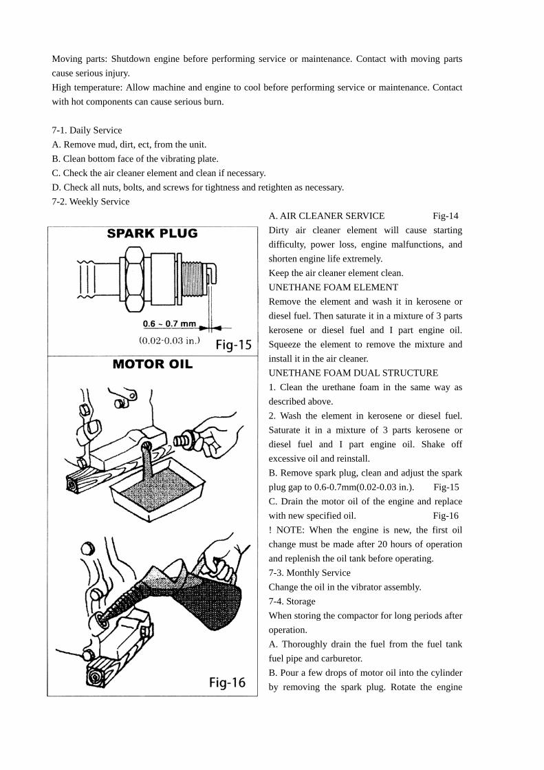
A. AIR CLEANER SERVICE Fig-14 Dirty air cleaner element will cause starting difficulty, power loss, engine malfunctions, and shorten engine life extremely. Keep the air cleaner element clean. UNETHANE FOAM ELEMENT Remove the element and wash it in kerosene or diesel fuel. Then saturate it in a mixture of 3 parts kerosene or diesel fuel and I part engine oil. Squeeze the element to remove the mixture and install it in the air cleaner. UNETHANE FOAM DUAL STRUCTURE 1. Clean the urethane foam in the same way as described above. 2. Wash the element in kerosene or diesel fuel. Saturate it in a mixture of 3 parts kerosene or diesel fuel and I part engine oil. Shake off excessive oil and reinstall. B. Remove spark plug, clean and adjust the spark plug gap to 0.6-0.7mm(0.02-0.03 in.). Fig-15 C. Drain the motor oil of the engine and replace with new specified oil. Fig-16 ! NOTE: When the engine is new, the first oil change must be made after 20 hours of operation and replenish the oil tank before operating. 7-3. Monthly Service Change the oil in the vibrator assembly. 7-4. Storage When storing the compactor for long periods after operation. A. Thoroughly drain the fuel from the fuel tank fuel pipe and carburetor. B. Pour a few drops of motor oil into the cylinder by removing the spark plug. Rotate the engine
several times by hand so that the cylinder interior is covered with oil. C. Clean the outer surface of the machine with an oil moistened cloth. Cover the unit and store in a humidity-free area. CARE AND PREVENTIVE MAINTENANCE Check the oil level in the motor crankcase daily. Check the vibrator oil level weekly. Inspect the rubber anti vibration mounts for wear or deterioration. Clean the underside of the plate regularly to prevent a build up of material. SERVICE Change the oil in the motor crankcase regularly to minimize wear. Inspect, clean and / or replace the motor air cleaner regularly, particularly when operating in a dusty environment. Inspect, clean and / or replace the spark plug regularly Check all fasteners for tightness as the machine is subiect to vibration. Check vee belt tension, wear and that it is running true. Adjust or replace as required.
! CAUTION Inspection and other services should always be carried out on hard and level ground with the engine shutdown. Inspection and maintenance Service Tables. 1. To make sure your plate compactor is always in good working condition before using, carry out the maintenance inspection in accordance with Tables 1 through 3.
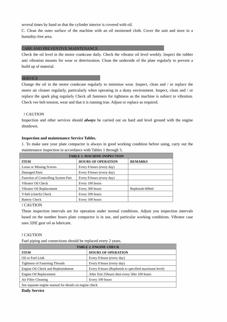
TABLE 1. MACHINE INSPECTION ITEM HOURS OF OPERATION REMARKS Loose or Missing Screws Every 8 hours (every day) Damaged Parts Every 8 hours (every day) Function of Controlling System Part Every 8 hours (every day) Vibrator Oil Check Every 100 hours Vibrator Oil Replacement Every 300 hours Replenish 600ml V-belt (clutch) Check Every 200 hours Battery Check Every 100 hours
! CAUTION These inspection intervals are for operation under normal conditions. Adjust you inspection intervals based on the number hours plate compactor is in use, and particular working conditions. Vibrator case uses 320£ gear oil as lubricant. ! CAUTION Fuel piping and connections should be replaced every 2 years.
TABLE 2. ENGINE CHECK ITEM HOURS OF OPERATION Oil or Fuel Leak Every 8 hours (every day) Tightness of Fastening Threads Every 8 hours (every day) Engine Oil Check and Replenishment Every 8 hours (Replenish to specified maximum level) Engine Oil Replacement After first 25hours then every 50to 100 hours Air Filter Cleaning Every 100 hours See separate engine manual for details on engine check
Daily Service
•Check for leakage of fuel or oil. •Check for loose screws including tightness. See Table 3 below (tightening torque), for retightening:
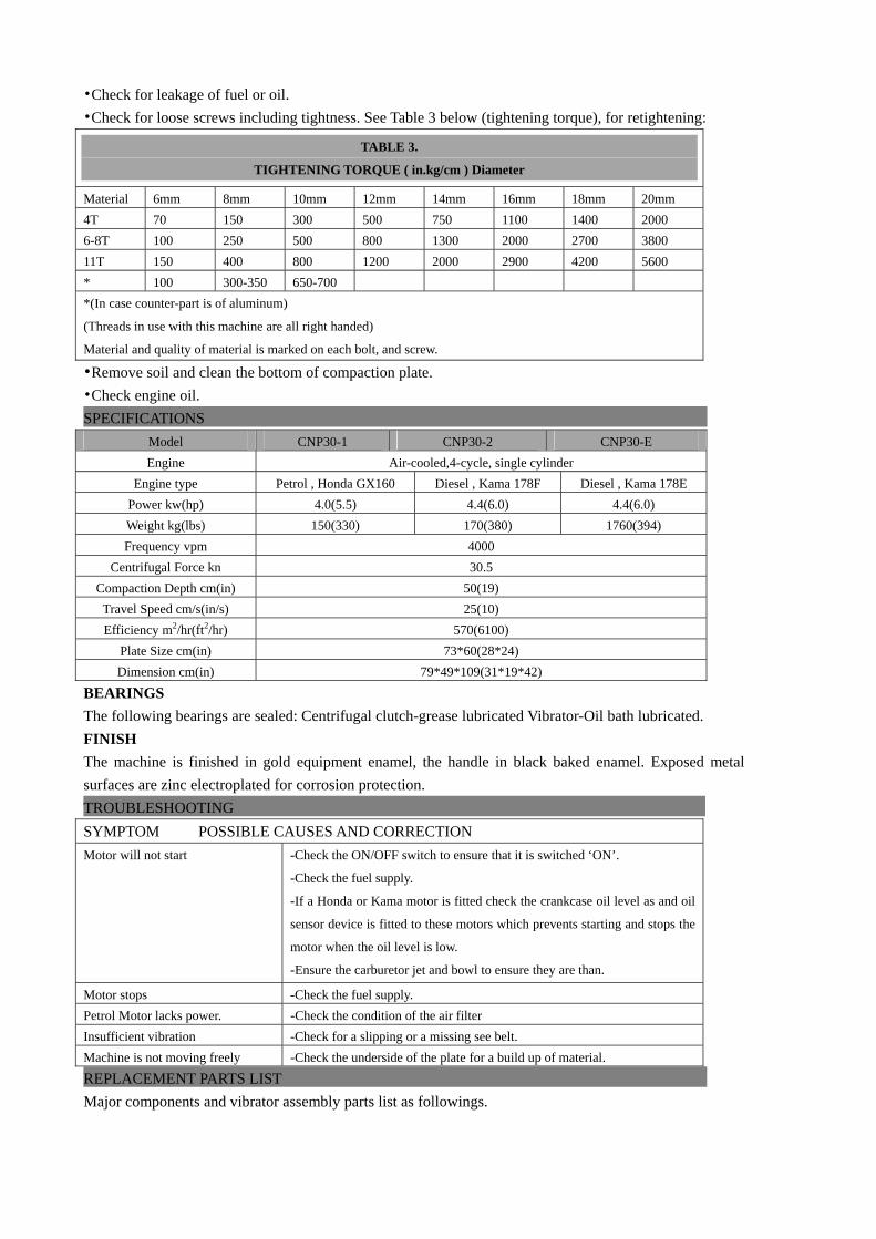
TABLE 3.
TIGHTENING TORQUE ( in.kg/cm ) Diameter
Material 6mm 8mm 10mm 12mm 14mm 16mm 18mm 20mm 4T 70 150 300 500 750 1100 1400 2000 6-8T 100 250 500 800 1300 2000 2700 3800 11T 150 400 800 1200 2000 2900 4200 5600 * 100 300-350 650-700 *(In case counter-part is of aluminum)
(Threads in use with this machine are all right handed)
Material and quality of material is marked on each bolt, and screw.
••Remove soil and clean the bottom of compaction plate. •Check engine oil. SPECIFICATIONS
Model CNP30-1 CNP30-2 CNP30-E Engine Air-cooled,4-cycle, single cylinder
Engine type Petrol , Honda GX160 Diesel , Kama 178F Diesel , Kama 178E Power kw(hp) 4.0(5.5) 4.4(6.0) 4.4(6.0) Weight kg(lbs) 150(330) 170(380) 1760(394) Frequency vpm 4000
Centrifugal Force kn 30.5 Compaction Depth cm(in) 50(19) Travel Speed cm/s(in/s) 25(10) Efficiency m2/hr(ft2/hr) 570(6100)
Plate Size cm(in) 73*60(28*24) Dimension cm(in) 79*49*109(31*19*42)
BEARINGS The following bearings are sealed: Centrifugal clutch-grease lubricated Vibrator-Oil bath lubricated. FINISH The machine is finished in gold equipment enamel, the handle in black baked enamel. Exposed metal surfaces are zinc electroplated for corrosion protection. TROUBLESHOOTING SYMPTOM POSSIBLE CAUSES AND CORRECTION Motor will not start -Check the ON/OFF switch to ensure that it is switched ‘ON’.
-Check the fuel supply.
-If a Honda or Kama motor is fitted check the crankcase oil level as and oil
sensor device is fitted to these motors which prevents starting and stops the
motor when the oil level is low.
-Ensure the carburetor jet and bowl to ensure they are than.
Motor stops -Check the fuel supply. Petrol Motor lacks power. -Check the condition of the air filter Insufficient vibration -Check for a slipping or a missing see belt. Machine is not moving freely -Check the underside of the plate for a build up of material.
REPLACEMENT PARTS LIST Major components and vibrator assembly parts list as followings.
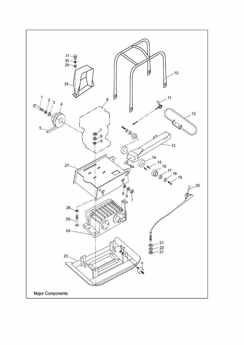

•Major components list ITEM NO. PART NO. DESCRIPTION QUANTITY
1. 30001. Hexagonal bolt M8*25 1
2. 30002. Washer, lock M8 1
3. 30003. Washer, Plat M8 1
4. 30004. Clutch assembly 1
5. 30005. V-belt 1
6. 30006. Engine 1
7. 30007. Nut M10 4
8. 30008. Washer, lock M10 4
9. 30009. Washer, plat M10 4
10. 30010. Guard hook 1
11. 30011. Throttle lever 1
12. 30012. Grip 1
13. 30013. Handle 1
14. 30014. Shock absorber 2
15. 30015. Hexagonal bolt M8*25 4
16. 30016. Rubber coupling 2
17. 30017. Rubber 2
18. 30018. Washer, Plat 12.5*40*2.5 2
19. 30019. Hexagonal bolt M12*65 2
20. 30020. Vibrator control 1
21. 30021. Nut M14*1.5*7 4
22. 30022. Washer, Plat M14 2
23. 30023. Vibrating plate 1
24. 30024. Vibrator assembly 1
25. 30025. Hexagonal bolt M10*45 4
26. 30026. Washer, Plat M10 4
27. 30027. Base 1
28. 30028. Belt cover(upper) 1
29. 30029. Washer, Plat M8 2
30. 30030. Washer, lock M8 2
31. 30031. Hexagonal bolt M8*20 2
32. 30032. Rubber collar 1
33. 30033. Shock absorber 4
34. 30034. Washer, lcok M12 4
35. 30035. Nut M12 4
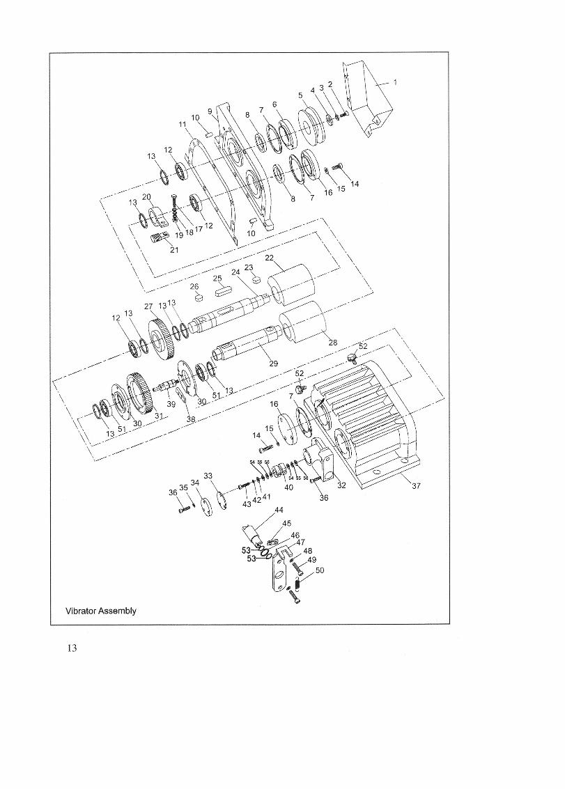

•Major components list ITEM NO. PART NO. DESCRIPTION QUANTITY
1. 30001 Belt cover (blow) 12. 30002 Screw M8*25 13. 30003 Washer, lock M8 14. 30004 Washer, Plat 8.5*32*2.5 15. 30005 Pulley, driven 16. 30006 Bearing cover / pulley 17. 30007 Packing 48. 30008 Oil seal 28*50*10 19. 30009 Case cover 110. 30010 Stop dowel 8*35 211. 30011 Packing 112. 30012 Bearing 42206 413. 30013 Stop ring 42 514. 30014 Socket head bolt M6*20 1315. 30015 Washer, lock M6 1316. 30016 Bearing cover / shut-off 217. 30017 Hexagonal bolt M8*60 118. 30018 Spring washer M8 2019. 30019 Nut M8 120. 30020 Stopper 121. 30021 Stop dowel M20*31-21 122. 30022 Eccentric rotator, drive 123. 30023 Key 8*7*25 124. 30024 Ecc. Rotary shaft, drive 125. 30025 Key 12*8*50 126. 30026 Key 12*8*20 127. 30027 Gear , drive 128. 30028 Eccentric rotator, driven 129. 30029 Ecc.rotary shaft, driven 130. 30030 Dial plate(R/L) 231. 30031 Gear, driven 132. 30032 Cylinder 133. 30033 Packing 134. 30034 Cover, cylinder 135. 30035 Washer, lock M5 336. 30036 Socket head bolt M5*10 337. 30037 Vibrating case 138. 30038 Knock pin 139. 30039 Position rod 140. 30040 Groove 141. 30041 Washer, copper 5*32*2.5 142. 30042 Washer, lock M5 143. 30043 Socket head bolt M5*10 144. 30044 Rotator 145. 30045 Lever 146. 30046 O-ring 347. 30047 Holder 148. 30048 Washer, lock M10 249. 30049 Socket head bolt M10*30 250. 30050 Spring 151. 30051 Bearing 16008 252. 30052 Plug, oil M12*1.25*10 253. 30053 Oil seal 254. 30054 Key 255. 30055 Plane bearing 256. 30056 key 2


Unit 10, Hatchmoor Industrial Estate, Hatherleigh, Okehampton, Devon EX20 3LPwww.lumag-gb.co.uk 01837 811741
Lumag Distribution Limited Company Number: 09267547 VAT Number: GB154566788 Hatherleigh
Plant and Tool Hire is a trading name of Lumag Distribution LTD